
HT-S7400 - Uncategorized ONKYO - Free user manual and instructions
Find the device manual for free HT-S7400 ONKYO in PDF.

| Product Type | 5.1 Channel Home Theater System |
| Brand | Onkyo |
| Model | HT-S7400 |
| Receiver Dimensions (W x H x D) | 17.2 x 6.6 x 12.9 inches |
| Receiver Weight | 19.8 lbs |
| Speaker Configuration | 4 satellite speakers, 1 center speaker, 1 powered subwoofer |
| Speaker Impedance | 6 ohms (satellites and center), 8 ohms (subwoofer) |
| Amplifier Power Output | 100 W per channel (1 kHz, 6 ohms, 1% THD) |
| Audio Decoding Formats | Dolby Digital, DTS, Dolby Pro Logic II |
| HDMI Inputs/Outputs | 2 inputs / 1 output (version 1.3a) |
| Video Inputs | Composite and component video |
| Audio Inputs | Digital optical, coaxial, analog RCA |
| Radio Tuner | FM/AM with 30 presets |
| Subwoofer Type | Powered, down-firing, 8-inch driver |
| Power Consumption | 350 W (receiver), standby <0.5 W |
| Remote Control | Includes full-function remote with batteries |
| Speaker Wire Connection | Spring clip terminals for satellites, push-type for center |
| Cleaning and Maintenance | Wipe with dry soft cloth; avoid solvents and liquids |
| Safety Certifications | UL, CE, FCC Class B |
| Spare Parts Availability | Contact Onkyo service center for replacement parts |
| Repair Service | Authorized service centers recommended for repairs |
Frequently Asked Questions - HT-S7400 ONKYO
User questions about HT-S7400 ONKYO
0 question about this device. Answer the ones you know or ask your own.
Ask a new question about this device
Download the instructions for your Uncategorized in PDF format for free! Find your manual HT-S7400 - ONKYO and take your electronic device back in hand. On this page are published all the documents necessary for the use of your device. HT-S7400 by ONKYO.
USER MANUAL HT-S7400 ONKYO
7.1ch Home Theater System
HT-S790
AV Receiver (HT-R540)
Front Speakers (SKF-540F)
Center Speaker (SKC-540C)
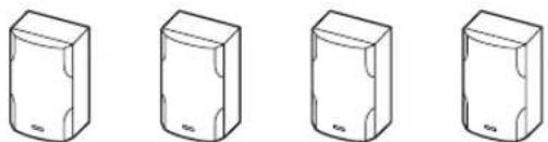
Surround Speakers (SKM-540S)
Surround Back Speakers (SKB-540)
Powered Subwoofer (SKW-540)
Instruction Manual
Thank you for purchasing an Onkyo 7.1ch Home Theater System. Please read this manual thoroughly before making connections and plugging in the unit. Following the instructions in this manual will enable you to obtain optimum performance and listening enjoyment from your new 7.1ch Home Theater System.
Please retain this manual for future reference.
Contents
Introduction 2
Connection 19
Turning On & First Time Setup..... 34
Basic Operation
Playing your AV components..... 36
Listening to the Radio...... 38
Enjoying the Listening Modes ..... 46
Advanced Operation 52
Troubleshooting 61
WARNING:
TO REDUCE THE RISK OF FIRE OR ELECTRIC SHOCK, DO NOT EXPOSE THIS APPARATUS TO RAIN OR MOISTURE.
CAUTION:
TO REDUCE THE RISK OF ELECTRIC SHOCK, DO NOT REMOVE COVER (OR BACK). NO USER-SERVICEABLE PARTS INSIDE. REFER SERVICING TO QUALIFIED SERVICE PERSONNEL.

WARNING
RISK OF ELECTRIC SHOCK
DO NOT OPEN
AVIS
RISQUE DE CHOC ELECTRIQUE
NE PAS OUVRIR


The lightning flash with arrowhead symbol, within an equilateral triangle, is intended to alert the user to the presence of uninsulated “dangerous voltage” within the product’s enclosure that may be of sufficient magnitude to constitute a risk of electric shock to persons.

The exclamation point within an equilateral triangle is intended to alert the user to the presence of important operating and maintenance (servicing) instructions in the literature accompanying the appliance.
Important Safety Instructions
-
Read these instructions.
-
Keep these instructions.
-
Heed all warnings.
-
Follow all instructions.
-
Do not use this apparatus near water.
-
Clean only with dry cloth.
-
Do not block any ventilation openings. Install in accordance with the manufacturer's instructions.
-
Do not install near any heat sources such as radiators, heat registers, stoves, or other apparatus (including amplifiers) that produce heat.
-
Do not defeat the safety purpose of the polarized or grounding-type plug. A polarized plug has two blades with one wider than the other. A grounding type plug has two blades and a third grounding prong. The wide blade or the third prong are provided for your safety. If the provided plug does not fit into your outlet, consult an electrician for replacement of the obsolete outlet.
-
Protect the power cord from being walked on or pinched particularly at plugs, convenience receptacles, and the point where they exit from the apparatus.
-
Only use attachments/accessories specified by the manufacturer.
-
Use only with the cart, stand, tripod, bracket, or table specified by the manufacturer, or sold with the apparatus. When a cart is used, use caution when moving the cart/ apparatus combination to avoid injury from tip-over.
PORTABLE CART WARNING

natural_image
Symbolic illustration of a person pushing a large object, enclosed in a circle with no text or symbols-
Unplug this apparatus during lightning storms or when unused for long periods of time.
-
Refer all servicing to qualified service personnel. Servicing is required when the apparatus has been damaged in any way, such as power-supply cord or plug is damaged, liquid has been spilled or objects have fallen into the apparatus, the apparatus has been exposed to rain or moisture, does not operate normally, or has been dropped.
-
Damage Requiring Service
Unplug the apparatus from the wall outlet and refer servicing to qualified service personnel under the following conditions:
A. When the power-supply cord or plug is damaged,
B. If liquid has been spilled, or objects have fallen into the apparatus,
C. If the apparatus has been exposed to rain or water,
D. If the apparatus does not operate normally by following the operating instructions. Adjust only those controls that are covered by the operating instructions as an improper adjustment of other controls may result in damage and will often require extensive work by a qualified technician to restore the apparatus to its normal operation,
E. If the apparatus has been dropped or damaged in any way, and
F. When the apparatus exhibits a distinct change in performance this indicates a need for service.
- Object and Liquid Entry
Never push objects of any kind into the apparatus through openings as they may touch dangerous voltage points or short-out parts that could result in a fire or electric shock.
The apparatus shall not be exposed to dripping or splashing and no objects filled with liquids, such as vases shall be placed on the apparatus.
Don't put candles or other burning objects on top of this unit.
- Batteries
Always consider the environmental issues and follow local regulations when disposing of batteries.
- If you install the apparatus in a built-in installation, such as a bookcase or rack, ensure that there is adequate ventilation.
Leave 20 cm (8") of free space at the top and sides and 10 cm (4") at the rear. The rear edge of the shelf or board above the apparatus shall be set 10 cm (4") away from the rear panel or wall, creating a flue-like gap for warm air to escape.
-
Recording Copyright —Unless it's for personal use only, recording copyrighted material is illegal without the permission of the copyright holder.
-
AC Fuse —The AC fuse inside the unit is not user-serviceable. If you cannot turn on the unit, contact your Onkyo dealer.
-
Care —Occasionally you should dust the unit all over with a soft cloth. For stubborn stains, use a soft cloth dampened with a weak solution of mild detergent and water. Dry the unit immediately afterwards with a clean cloth. Don't use abrasive cloths, thinners, alcohol, or other chemical solvents, because they may damage the finish or remove the panel lettering.
4. Power
WARNING
BEFORE PLUGGING IN THE UNIT FOR THE FIRST TIME, READ THE FOLLOWING SECTION CAREFULLY.
AC outlet voltages vary from country to country. Make sure that the voltage in your area meets the voltage requirements printed on the unit's rear panel (e.g., AC 230–240 V, 50 Hz or AC 120 V, 60 Hz).
Pressing the [STANDBY/ON] button to select Standby mode does not fully shutdown the unit. If you do not intend to use the unit for an extended period, remove the power cord from the AC outlet.
- Never Touch this Unit with Wet Hands—Never handle this unit or its power cord while your hands are wet or damp. If water or any other liquid gets inside this unit, have it checked by your Onkyo dealer.
6. Handling Notes
- If you need to transport this unit, use the original packaging to pack it how it was when you originally bought it.
- Do not leave rubber or plastic items on this unit for a long time, because they may leave marks on the case.
- This unit's top and rear panels may get warm after prolonged use. This is normal.
- If you do not use this unit for a long time, it may not work properly the next time you turn it on, so be sure to use it occasionally.
For U.S. models
FCC Information for User CAUTION:
The user changes or modifications not expressly approved by the party responsible for compliance could void the user's authority to operate the equipment.
NOTE:
This equipment has been tested and found to comply with the limits for a Class B digital device, pursuant to Part 15 of the FCC Rules. These limits are designed to provide reasonable protection against harmful interference in a residential installation.
This equipment generates, uses and can radiate radio frequency energy and, if not installed and used in accordance with the instructions, may cause harmful interference to radio communications. However, there is no guarantee that interference will not occur in a particular installation. If this equipment does cause harmful interference to radio or television reception, which can be determined by turning the equipment off and on, the user is encouraged to try to correct the interference by one or more of the following measures:
- Reorient or relocate the receiving antenna.
- Increase the separation between the equipment and receiver.
- Connect the equipment into an outlet on a circuit different from that to which the receiver is connected.
- Consult the dealer or an experienced radio/TV technician for help.
For Canadian Models
NOTE: THIS CLASS B DIGITAL APPARATUS COMPLIES WITH CANADIAN ICES-003.
For models having a power cord with a polarized plug: CAUTION: TO PREVENT ELECTRIC SHOCK, MATCH WIDE BLADE OF PLUG TO WIDE SLOT, FULLY INSERT.
- The speaker cabinets are made out of wood and are therefore sensitive to extreme temperatures and humidity, do not put them in locations subject to direct sunlight or in humid places, such as near an air conditioner, humidifier, bathroom, or kitchen.
- Do not put water or other liquids close to the speakers. If liquid is spilled over the speakers, the drive units may be damaged.
- Speakers should only be placed on sturdy, flat surfaces that are free from vibration. Putting them on uneven or unstable surfaces, where they may fall and cause damage, will affect the sound quality.
- Subwoofer is designed to be used in the upright vertical position only. Do not use it in the horizontal or tilted position.
- If the unit is used near a turntable, CD player or DVD player, howling or slipping of sound may occur. To prevent this, move the unit away from the turntable, CD player or DVD player otherwise lower the unit's output level.
Using Close to a TV or Computer
TVs and computer monitors are magnetically sensitive devices and as such are likely to suffer discoloration or picture distortion when conventional speakers are placed nearby. To prevent this, the SKF-540F and SKC-540C feature internal magnetic shielding. In some situations, however, discoloration may still be an issue, in which case you should turn off your TV or monitor, wait 15 to 30 minutes, and then turn it back on again. This normally activates the degaussing function, which neutralizes the magnetic field, thereby removing any discoloration effects. If discoloration problems persist, try moving the speakers away from your TV or monitor. Note that discoloration can also be caused by a magnet or demagnetizing tool that's too close to your TV or monitor.
Input Signal Warning
The speakers can handle the specified input power when used for normal music reproduction. If any of the following signals are fed to them, even if the input power is within the specified rating, excessive current may flow in the speaker coils, causing burning or wire breakage:
- Interstation noise from an untuned FM radio.
- Sound from fast-forwarding a cassette tape.
- High-pitched sounds generated by an oscillator, electronic musical instrument, and so on.
- Amplifier oscillation.
- Special test tones from audio test CDs and so on.
- Thumps and clicks caused by connecting or disconnecting audio cables (Always turn off your amplifier before connecting or disconnecting cables.)
- Microphone feedback.
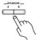
Speaker Sets A and B
You can use two sets of speakers with the AV receivers speaker set A and speaker set B.
Speaker set A (included speakers) should be used in your main listening room for up to 7.1-channel playback.
*While speaker set B is on, speaker set A is reduced to 5.1-channel playback.
Speaker set B (not included) can be used in another room and offers 2-channel stereo playback.
*Only analog input sources are output by speaker set B.
AV receiver
or
Remote
controller

| Speaker set A Speaker set B Indicator Output | |||
| On | On |   | Set A: 5.1 channelsSet B: 2 channels |
| Off Set A: 7.1 channels | |||
| Off | On Set B: 2 channels B | ||
| Off No sound | |||
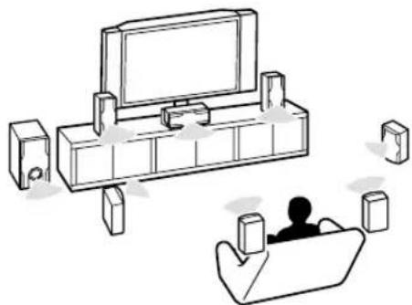
Speaker Set A: Main Room
Front left and right speakers (SKF-540F)
These output the overall sound. Their role in a home theater is to provide a solid anchor for the sound image. They should be positioned facing the listener at about ear level, and equally spaced from the TV. Angle them inward.
Center speaker (SKC-540C)
This speaker enhances the front left and right speakers, making sound movements distinct and providing a full sound image. For movies it's used mainly for dialog. Position it close to your TV facing forward at about ear level, or at the same height as the front left and right speakers.
Subwoofer (SKW-540)
The subwoofer handles the bass sounds of the LFE (Low-Frequency Effects) channel. In general, a good bass sound can be obtained by installing the subwoofer in a front corner, or at one-third the way along the wall, as shown.
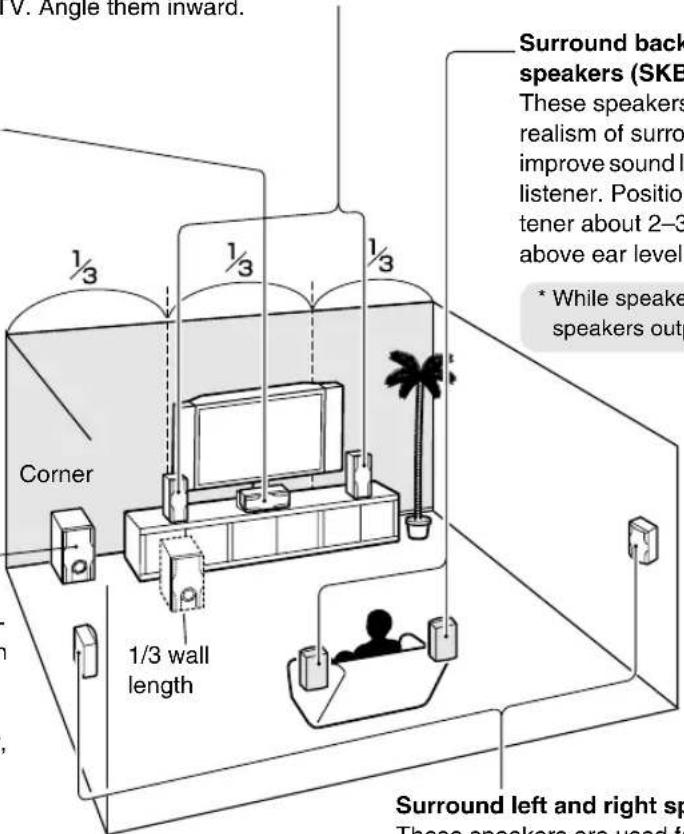
Surround back left and right speakers (SKB-540)
These speakers further enhance the realism of surround sound and improve sound localization behind the listener. Position them behind the listener about 2–3 feet (60–100 cm) above ear level.
* While speaker set B is on, these speakers output no sound.
Speaker Set B: Sub Room
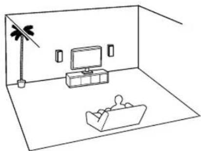
natural_image
Simple line drawing of a living room with TV, sofa, lamp, and person (no text or symbols)Surround left and right speakers (SKM-540S)
These speakers are used for precise sound positioning and to add realistic ambience. Position them at the sides of the listener, or slightly behind, about 2–3 feet (60–100 cm) above ear level. Ideally they should be equally spaced from the listener.
Make sure you have the following items:
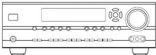
natural_image
Line drawing of a portable electronic device with ports and buttons (no text or symbols)AV receiver (HT-R540)
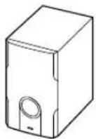
Subwoofer (SKW-540)
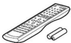
Remote controller & two batteries (AA/R6)

(Red) (White)
Speaker cable for front speakers 15 ft. (4.5 m)

Indoor FM antenna

(Green)
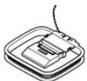
AM loop antenna
Speaker cable for center speaker 10 ft. (3 m)

natural_image
Two bundles of coiled wire, labeled (Blue) and (Gray), shown side by side (no additional text or symbols)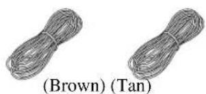
natural_image
Two bundles of coiled wire, labeled (Brown) and (Tan), shown side by side (no additional text or symbols)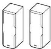
Front speakers (SKF-540F)
Speaker cables for surround speakers 30 ft. (9 m)
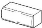
Center speaker (SKC-540C)

RCA cable for subwoofer connection 10 ft. (3 m)
natural_image
Five identical 3D rectangular blocks with rounded corners, shown in isometric view (no text or symbols)Surround and Surround back speakers (SKM-540S/SKB-540)
* In catalogs and on packaging, the letter at the end of the product name indicates the color. Specifications and operation are the same regardless of color.
Amplifier
- 7-channel amplifier
- 110 watts per channel rms into 8 ohms, 2 channels driven at 1 kHz, less than 0.9% total harmonic distortion (FTC rating)
• WRAT (Wide Range Amplifier Technology)
• Optimum Gain Volume Circuitry - OR-EQ (OptiResponse Equalizer) *1 function
Processing
• Dolby ^2 Digital EX and Dolby Pro Logic IIx
• DTS, DTS-ES Matrix/Discrete, DTS Neo:6, and DTS 96/24 ^3
- Neural Surround ^*4 (North American models only)
• CinemaFILTER function
• Linear PCM 192 kHz/24-bit D/A converters on all channels
• Pure Audio listening mode (not North American model)
- P o werful and highly accurate 32-bit DSP processing
Audio/Video
- Adjustable crossover (40, 50, 60, 80, 100, 120, 150, 200 Hz)
• HDTV-capable component video (3 inputs, 1 output)
• 3 S-Video inputs, 2 outputs
• 4 assignable digital inputs (3 optical, 1 coaxial) - Subwoofer pre out
• Color-coded 7.1 multichannel input for use with Super Audio CD and DVD-Audio
• A/B speaker drive
• Color-coded speaker terminal posts
Tuner
- XM ^5 Satellite Radio (North American models only)
*XM Passport System required; sold separately.
• 40 AM/FM/XM presets - AM/FM auto tuning
Remote Controller
- Preprogrammed for use with other AV components
Speaker
• Color-coded speaker terminals and speaker cables
- Subwoofer Auto standby function
- Magnetically shielded front and center speakers
- Floating tweeter on the front and center speakers
*1 OptiResponse, and OR-EQ are trademarks of Onkyo Corporation.
\*2 DOLBY DIGITAL·EX PROLOGIC IX
Manufactured under license from Dolby Laboratories.
"Dolby", "Pro Logic" and the double-D symbol are registered trademarks of Dolby Laboratories.
\*3 dts 96 24 ES NEOS
“DTS,” “DTS 96/24,” “DTS-ES,” and “Neo:6” are trademarks of Digital Theater Systems, Inc.
\*4 neural SURROUND.
Neural Surround name and related logos are trademarks owned by Neural Audio Corporation.
\*5 ((XM)) READY
XM Ready ^® , XM Public Radio ^™ are trademarks of XM Satellite Radio Inc. ©2005 XM Satellite Radio Inc. All rights reserved. All other trademarks are the property of their respective owners.
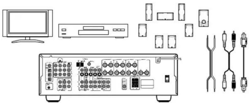
Getting Started in Five Easy Steps
1. Hookup
Connect the AV receiver to your AV system.
page 19
natural_image
Line drawing of electronic equipment including a monitor, CD, connectors, and various cables (no text or symbols)2. Turning On
With the hookup complete, you're ready to switch on.
page 34
3. First Time Setup
A few simple settings to get the very best from your system.
page 35
4. Playing Your AV Components
Enjoying movies and music.
page 36
5. Using the Listening Modes
Time to really enjoy your home theater system!
page 46
natural_image
Line drawing of a person sitting in a chair with a TV on a wall, next to a desk and wall-mounted devices (no text or symbols)Introduction
Important Safety Instructions ....2
Precautions ....3
Speaker Precautions ....4
Enjoying Home Theater....5
Speaker Sets A and B 5
Package Contents......6
Features 7
Getting to Know the AV Receiver......10
Remote Controller....13
Speakers ....18
Connection
Connecting Your Speakers ....19
Connecting Antennas....20
Connecting Your Components .....22
About AV Connections ......22
Connecting Audio and Video Signals to the AV Receiver ....23
Which Connections Should I Use?......23
TV or Projector....24
DVD player....25
VCR or DVD Recorder for Playback .....27
VCR or DVD Recorder for Recording.....28
Camcorder, Games Console, or Other Device....28
Satellite, Cable, Set-top box, or Other Video Source ....29
CD Player or Turntable....30
HDD-compatible Component ....31
Cassette, CDR, MiniDisc, or DAT Recorder....32
Connecting the Power Cord of Another Component 32
Connecting Onkyo Components ....33
Connecting the Power Cord ....33
Turning On & First Time Setup
Turning On the AV Receiver ....34
First Time Setup....35
Assigning Digital Inputs to Input Sources....35
Changing the Input Display ....35
Basic Operation
Playing Your AV Components .... 36
Basic AV Receiver Operation 36
Using the Multichannel DVD Input...... 37
Displaying Source Information.... 37
Listening to the Radio.... 38
Listening to AM/FM stations 38
Presetting AM/FM Stations and XM Channels.... 39
Listening to XM Satellite Radio® (North American Models Only) ...... 40
Common Functions.... 44
Setting the Display Brightness.... 44
Adjusting the Bass and Treble.... 44
Muting the AV Receiver 44
Using the OptiResponse Equalizer...... 44
Using the Sleep Timer 45
Using Headphones 45
Adjusting Speaker Levels 45
Enjoying the Listening Modes
Using the Listening Modes...... 46
Selecting Listening Modes.... 46
About the Listening Modes 48
Using the Late Night Function 50
Using the CinemaFILTER.... 50
Using the Audio Adjust Settings .... 50
Advanced Operation
Advanced Setup 52
Advanced Speaker Settings 52
Digital Input Signal Formats 56
Correcting Sound and Picture Sync .... 56
Recording.... 57
Controlling Other Components...... 58
Entering Remote Control Codes...... 58
Remote Control Codes for Onkyo Components Connected via R.I...... 59
Resetting REMOTE MODE Buttons ..... 59
Resetting the Remote Controller 59
Troubleshooting 61
If you can't resolve an issue, try resetting the AV receiver by holding down the [VIDEO 1] button and pressing the [STANDBY/ON] button.
Specifications 65
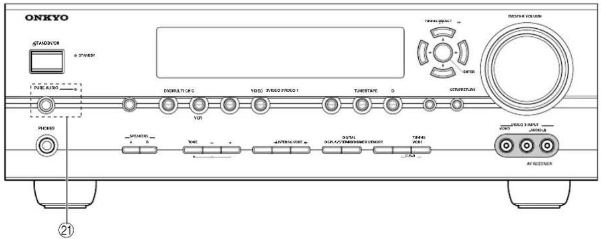
Front Panel
North American Model
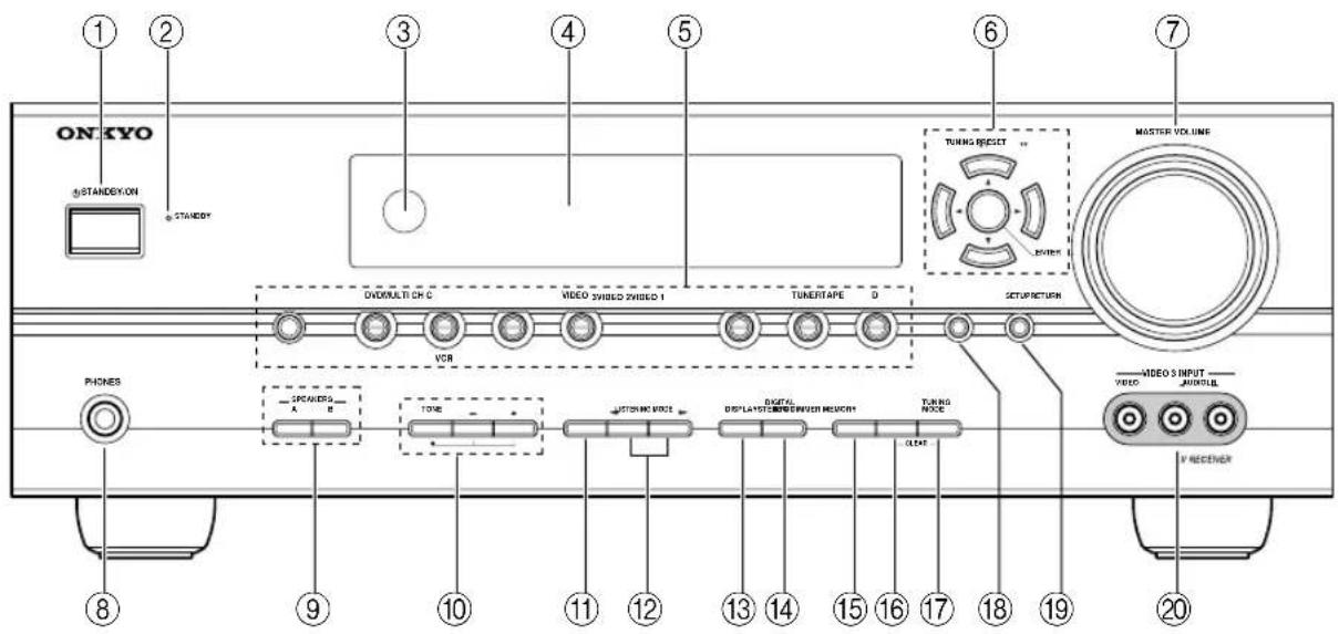
Other Models
For detailed information, see the pages in parentheses.
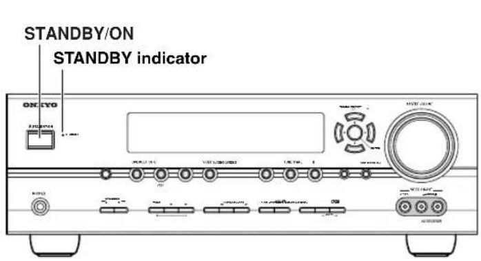
① STANDBY/ON button (34)
Sets the AV receiver to On or Standby.
② STANDBY indicator (34)
Lights up when the AV receiver is on Standby and flashes while a signal is being received from the remote controller.
③ Remote-control sensor (13)
Receives control signals from the remote controller.
④ Display
See "Display" on page 11.
⑤ Input selector buttons (36)
Select the input sources.
The [MULTI CH] button selects the multichannel DVD input.
⑥ Arrow/TUNING/PRESET and ENTER buttons
When AM, FM, or XM is selected, the TUNING [▲] ▼] buttons are used for radio tuning, and the PRESET [◀] buttons are used to select radio presets (see page 39). With the setup menus, they work as arrow buttons and are used to select and set items. The ENTER button is also used with the setup menus.
⑦ MASTER VOLUME control (36)
Sets the volume of the AV receiver to MIN, 1 through 79, or MAX.
⑧ PHONES jack (45)
This 1/4-inch phone jack is for connecting a standard pair of stereo headphones for private listening.
⑨ SPEAKERS A and B buttons (5, 36)
Turn speaker sets A and B on or off.
⑩ TONE, [-], and [+] buttons (44)
Used to adjust the bass and treble.
⑪ STEREO button (46)
Selects the Stereo listening mode.
⑫ LISTENING MODE [◀] ▶buttons (46)
Select the listening modes.
⑬ DISPLAY button (37)
Displays various information about the currently selected input source.
⑭ DIGITAL INPUT button (35, 56)
Used to assign the digital inputs and to specify the format of digital input signals.
⑮ DIMMER button (44)
Adjusts the display brightness.
⑯ MEMORY button (39)
Used when storing or deleting radio presets.
⑰ TUNING MODE button (38)
Selects the Auto or Manual tuning mode for AM and FM radio.
⑱ RETURN button
Selects the previously displayed setup menu.
⑲ SETUP button
Used to access the setup menus.
⑳ VIDEO 3 INPUT (28, 57)
Used to connect a camcorder, games console, and so on. There are jacks for composite video and analog audio.
②1 PURE AUDIO button and indicator (46) The North American model doesn't have this button and indicator.
Selects the Pure Audio listening mode. The indicator lights up when this mode is selected.
Display
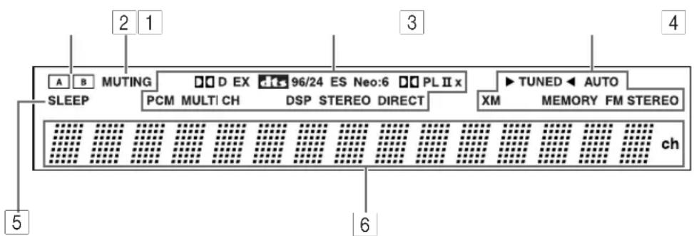
For detailed information, see the pages in parentheses.
1 A and B speaker indicators (5, 36) Indicator A lights up when speaker set A is on. Indicator B lights up when speaker set B is on.
2 MUTING indicator (44) Flashes while the AV receiver is muted.
3 Listening mode and format indicators (48) Show the selected listening mode and the format of digital audio signals.
4 Radio indicators TUNED (38): Lights up when tuned to a radio station.
AUTO (38): For AM and FM radio, lights up when Auto Tuning is selected, and disappears when Manual Tuning mode is selected.
XM (North American models only) (40): Lights up when XM radio is selected.
MEMORY (39): Lights up when presetting radio stations.
FM STEREO (38): Lights up when tuned to a stereo FM station.
5 SLEEP indicator (45)
Lights up when the Sleep function has been set.
6 Message area
Displays various information about the selected input source.
Rear Panel
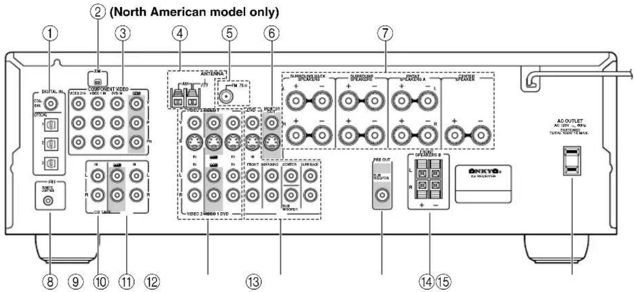
① DIGITAL IN OPTICAL 1, 2, 3, and COAXIAL These optical and coaxial digital audio inputs are for connecting components with optical or coaxial digital audio outputs, such as CD and DVD players.
② XM antenna (on North American models) This jack is for connecting an XM Passport System, sold separately (see page 40).
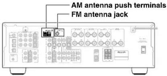
③ COMPONENT VIDEO A DVD player, TV, or other component that supports component video can be connected here.
④ AM ANTENNA These push terminals are for connecting an AM antenna.
⑤ FM ANTENNA This jack is for connecting an FM antenna.
⑥ MONITOR OUT The S-Video or composite video output should be connected to a video input on your TV or projector.
These terminal posts are for connecting speaker set A.
⑧ RI REMOTE CONTROL This Remote Interactive jack can be connected to the jack on another -capable Onkyo component. To use you must make an analog audio connection (RCA) between the AV receiver and the other component, even if they are connected digitally.
⑨ CD IN This analog audio input is for connecting a CD player's analog audio output.
⑩ TAPE IN/OUT This analog audio input and output are for connecting a recorder with an analog audio input and output, such as a cassette deck, MD recorder, etc.
⑪ VIDEO 1 IN/OUT and VIDEO 2 IN The VIDEO 1 inputs and outputs can be used to connect a VCR. The VIDEO 2 inputs can be used to connect another video source (e.g., cable/satellite receiver, set-top box, etc).
⑫ DVD IN These jacks can be used to connect a DVD player with an analog multichannel audio output for SACD and DVD-Audio playback.
⑬ SUBWOOFER PRE OUT A powered subwoofer can be connected here.
⑭ FRONT SPEAKERS B These push terminals are for connecting speaker set B.
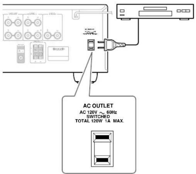
⑮ AC OUTLET This switched AC outlet can be used to supply power to another AV component. The type of outlet depends on the country in which you purchased your AV receiver.
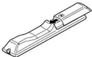
Installing the Batteries
1 To open the battery compartment, press the small hollow and slide open the cover.
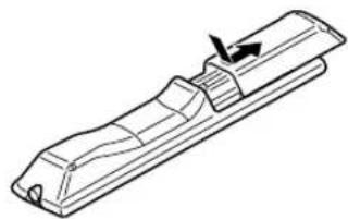
natural_image
Technical line drawing of a mechanical component with an arrow indicating direction (no text or symbols)2 Insert the two supplied batteries (AA/R6) in accordance with the polarity diagram inside the battery compartment.
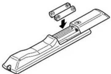
natural_image
Technical line drawing of a mechanical component with an arrow indicating assembly or transformation (no text or symbols present)3 Slide the cover shut.
natural_image
Technical line drawing of a mechanical component with a handle and mounting bracket (no text or symbols)Notes:
- If the remote controller doesn't work reliably, try replacing the batteries.
- Don't mix new and old batteries or different types of batteries.
- If you intend not to use the remote controller for a long time, remove the batteries to prevent damage from leakage or corrosion.
- Expired batteries should be removed as soon as possible to prevent damage from leakage or corrosion.
Aiming the Remote Controller
When using the remote controller, point it toward the AV receiver's remote control sensor, as shown below.
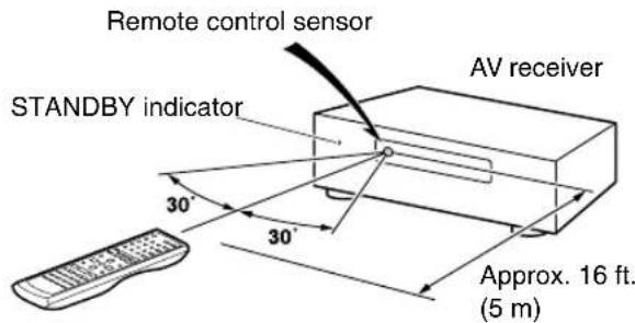
Notes:
- The remote controller may not work reliably if the AV receiver is subjected to bright light, such as direct sunlight or inverter-type fluorescent lights. Keep this in mind when installing.
- If another remote controller of the same type is used in the same room, or the AV receiver is installed close to equipment that uses infrared rays, the remote controller may not work reliably.
- Don't put anything on top of the remote controller, such as a book or magazine, because a button may be pressed continuously, thereby draining the batteries.
- The remote controller may not work reliably if the AV receiver is installed in a rack behind colored glass doors. Keep this in mind when installing.
- The remote controller will not work if there's an obstacle between it and the AV receiver's remote control sensor.
Using the Remote Controller
Including the AV receiver, the remote controller can be used to control up to seven different components. The remote controller has a specific operating mode for use with each type of component. Modes are selected by using the six REMOTE MODE buttons.
■ RECEIVER/TAPE Mode
In RECEIVER/TAPE mode, you can control the AV receiver and an Onkyo cassette recorder connected via RI

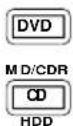
■ DVD and CD/MD/CDR/HDD Modes
With these modes, you can control a DVD player and CD, MD, CDR, or HDD player or recorder. By entering the appropriate remote control code, you can control Onkyo components or components made by other manufacturers (see page 58).
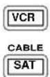
■ TV, VCR and SAT/CABLE Modes
With these modes, you can control a TV, VCR, and satellite or cable receiver. You must enter the appropriate remote control code first (see page 58).

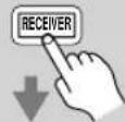
| 1-REMOTE MODE-TAPE[IMAGE] | Press one of the REMOTE MODE buttons to select a mode. |
| 2 | Use the buttons supported by that mode to control the component.RECEIVER/TAPE mode:see right columnDVD mode:see page 16CD/MD/CDR/HDD mode:see page 17TV, VCR, SAT/CABLE mode:see page 60 |
Note:
Some of the remote controller operations described in this manual may not work as expected with other components.
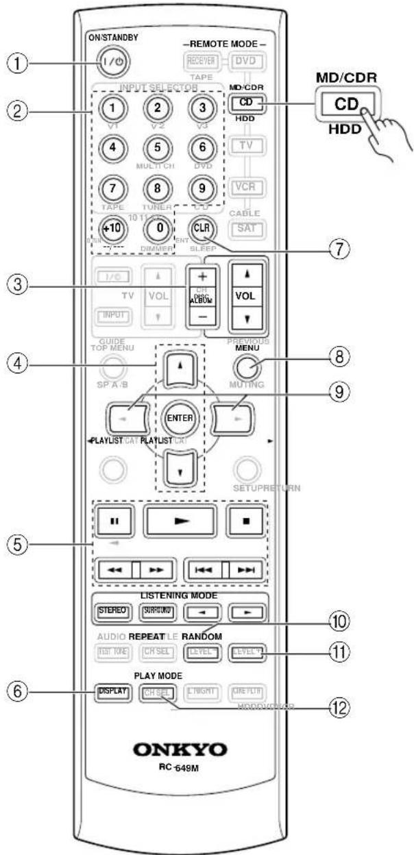
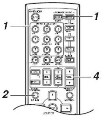
RECEIVER/TAPE Mode
RECEIVER/TAPE mode is used to control the AV receiver. It can also be used to control an Onkyo cassette recorder connected via RI
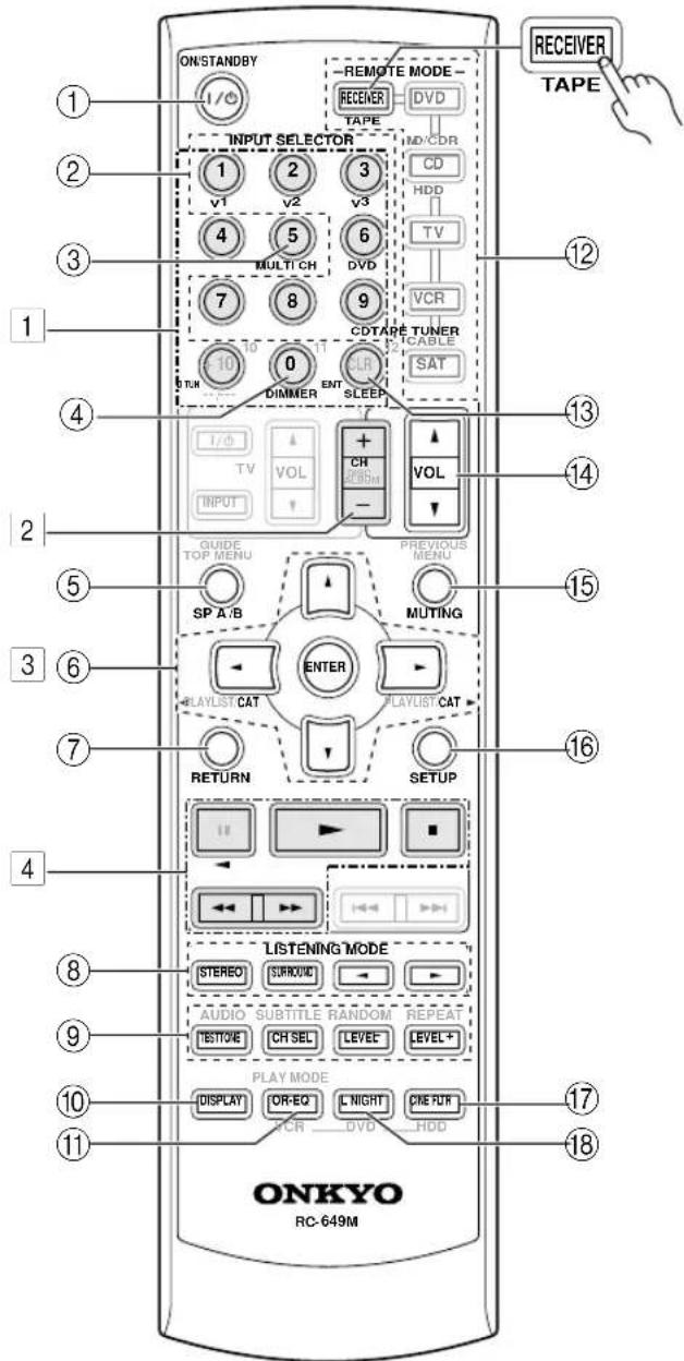
Buttons | 1, | 2, | 3|, and | 4 are used when the TUNER or TAPE input is selected.
For detailed information, see the pages in parentheses.
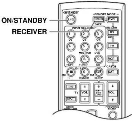
① ON/STANDBY button (34) Sets the AV receiver to On or Standby.
② INPUT SELECTOR buttons (36) Used to select the input sources.
③ MULTI CH button (37) Selects the multichannel DVD input.
④ DIMMER button (44) Adjusts the display brightness.
⑤ SP A/B button (5, 36) Used to turn speaker sets A and B on or off.
⑥ Arrow [√] / [V] / [ ] ▶ and ENTER buttons Used to select and adjust settings.
⑦ RETURN button Selects the previously displayed setup menu.
⑧ LISTENING MODE buttons (46) Used to select the listening modes. These buttons work in all remote controller modes.
STEREO button
Selects the Stereo listening mode.
SURROUND button
Selects the Dolby and DTS listening modes and the Neural Surround listening mode (North American model only).

Used to select the available listening modes.
⑨ TEST TONE, CH SEL, LEVEL-, and LEVEL+ buttons (34, 45, 53)
Used to adjust the level of each speaker.
⑩ DISPLAY button (37)
Displays various information about the selected input source.
⑪ OR-EQ button (44)
Turns on the OptiResponse Equalizer, which optimizes performance when the HT-R540 is used with the speakers included in this package. When the OptiResponse Equalizer is on, you can enjoy a powerful sound with movies or music even at low volume levels.
⑫ REMOTE MODE buttons (14)
Used to select the remote controller modes. When a remote controller button is pressed, the REMOTE MODE button for the currently selected mode lights up.
⑬ SLEEP button (45)
Used with the Sleep function.
⑭ VOL [V[ ] button (36)
Adjusts the volume of the AV receiver regardless of the currently selected remote controller mode.
⑮ MUTING button (44)
Mutes or unmutes the AV receiver.
⑯ SETUP button
Used to access the setup menus.
⑰ CINE FLTR button (50)
Used with the CinemaFILTER function.
⑱ L NIGHT button (50)
Used with the Late Night function.
■ Buttons used when the TUNER input is selected
To select the Tuner (AM/FM/XM) as the input source, press:

1 Number, D TUN, and ENT buttons (39, 41)
Used to select AM and FM radio stations and XM radio channels directly.
2 CH +/- button (39)
Used to select radio presets.
3 Arrow [ʌ/ɪ/ː] ▶ nd ▶ ENTER buttons
For AM and FM, the Up and Down [▲] cuttons are used for tuning.
North American model only
For XM, the Up and Down [▲] buttons are used to select channels, and the [ENTER] button is used to change the search mode. The Left and Right [▲] buttons are used to select categories.
■ Buttons used when the TAPE input is selected
To select your Cassette deck as the input source, press:

4 Playback buttons
On twin cassette decks, only deck B can be controlled.
Play [▶] button
Starts playback.
Stop [button
Stops playback.
Reverse Play [button]
Starts reverse playback.
Rewind and FF [1/4] buttons
The Rewind [◀button starts rewind. The FF [▶▶] button starts fast forward.
DVD Mode
By default, the remote controller is set to control an Onkyo DVD player.
Toselect your DVD player as the input source, press:
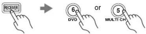
① ON/STANDBY button Sets the DVD player to On or Standby.
② Number buttons
Used to enter title, chapter, and track numbers and times for locating specific points.
③ DISC +/- button
Selects discs on a DVD changer.
④ TOP MENU button Selects a DVD's top menu.
⑤ Arrow [ ][ ][ ][ ] and ENTER buttons
Used to navigate DVD menus and the DVD player's onscreen setup menus.
⑥ RETURN button Exits the DVD player's onscreen setup menus.
⑦ Playback buttons
From left to right: Pause, Play, Stop, Fast Reverse, Fast Forward, Previous, and Next.
⑧ SUBTITLE button Selects subtitles.
⑨ AUDIO button
Selects foreign language soundtracks and audio formats (e.g., Dolby Digital or DTS).
⑩ DISPLAY button
Displays information about the current disc, title, chapter, or track, including elapsed time, remaining time, total time, and so on.
⑪ CLR button
Cancels functions and clears entered numbers.
⑫ MENU button
Displays a DVD's menu.
⑬ SETUP button
Used to access the DVD player's onscreen setup menus.
⑭ RANDOM button
Used with the random playback function.
⑮ REPEAT button
Used with the repeat playback functions.
⑯ VCR, DVD, and HDD buttons
Used to select VCR, HDD (hard disk drive), or DVD playback on a VCR/DVD recorder with a built-in hard disk drive.
⑰ PLAY MODE button
Selects play modes on components with selectable play modes.
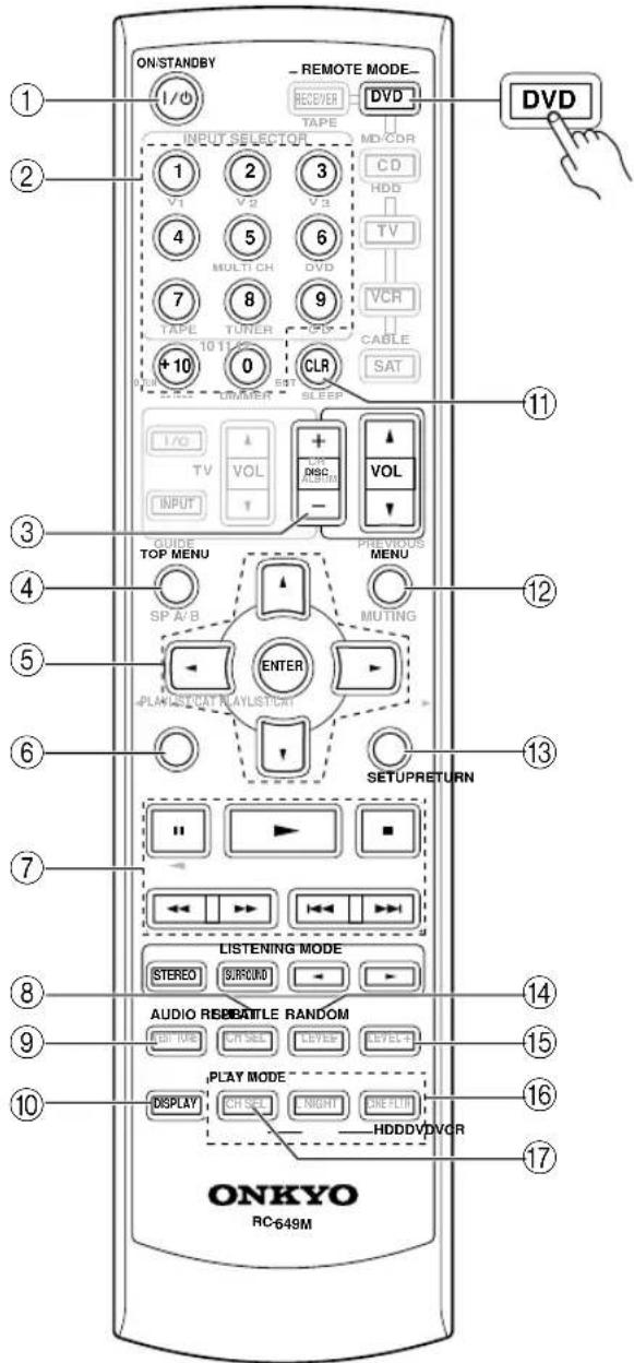
CD/MD/CDR/HDD Mode
By default, the remote controller is set to control an Onkyo CD player.
To select the input source, press:
flowchart
graph TD
    A["RECEIVER"] --> B["CD player"]
    A --> C["MD or CD recorder"]
    A --> D["Next generation HDD-compatible component"]
    B --> E["9"]
    B --> F["7"]
    B --> G["7"]
    C --> H["or"]
    C --> I["V2"]
* If you're using an MD, CDR, or HDD component, you must change the Input Display (see page 35).
① ON/STANDBY button
Sets the component to On or Standby.
② Number buttons
Used to enter track numbers and times for locating specific points on CD/MD players.
③ DISC/ALBUM +/- button
Selects discs on a CD changer, or the next or previous album on an HDD-compatible component.
④ Arrow [A] and ENTER buttons
Used to navigate menus on an HDD-compatible component.
⑤ Playback buttons
From left to right: Pause, Play, Stop, Fast Reverse, Fast Forward, Previous and Next.
⑥ DISPLAY button
Displays information about the current disc or track on a CD player or MD/CD recorder, including elapsed time, remaining time, total time, and so on. On an HDD-compatible component, it turns on the back light for 30 seconds.
⑦ CLR button
Cancels functions and clears entered numbers on a CD player or MD/CD recorder.
⑧ MENU button
Used to navigate menus on an HDD-compatible component.
⑨ PLAYLIST [◀] [ ] buttons
Selects the previous or next playlist on an HDD-compatible component.
⑩ RANDOM button
Used with the random/shuffle playback function.
⑪ REPEAT button
Used with the repeat playback functions.
⑫ PLAY MODE button
Used to select play modes on components with selectable play modes.
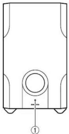
Subwoofer (SKW-540)
For detailed information, see the pages in parentheses.
Front
natural_image
Technical line drawing of a mechanical component with a circular feature and base, labeled with number ① (no text or symbols on the diagram itself)Rear
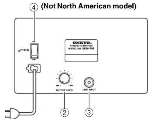
To AC outlet
① STANDBY/ON indicator
Red: Subwoofer in standby mode
Green: Subwoofer on
With the Auto Standby function, the SKW-540 automatically turns on when an input signal is detected in Standby mode. When there's no input signal for a while, the SKW-540 automatically enters Standby mode.
② OUTPUT LEVEL control (36)
This control is used to adjust the volume of the subwoofer.
③ LINE INPUT (19)
This RCA input should be connected to the subwoofer pre out on the AV receiver with supplied RCA cable.
④ POWER switch (Not North American model) (34)
Press this switch to the ON position to turn on the power. Press it to the OFF position to turn off the power.
Note:
The Auto Standby function turns the subwoofer on when the input signal exceeds a certain level. If the Auto Standby function does not work reliably, try slightly increasing or decreasing the subwoofer output level on the AV receiver (page 53).
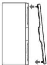
■ Attaching and detaching the speaker grilles
Front and Center speakers have detachable grilles. Use the following method to attach or detach the grilles.
- While holding the bottom edge of the speaker grille with your both hands, pull it gently toward you to remove the bottom of the grille.
- In the same way, gently pull the upper edge of the speaker grille toward you to remove it from the main unit.
- To replace the grill, push the projections at the corners into the grille plug holes on the speaker cabinet.
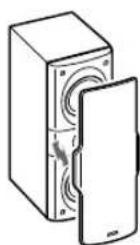
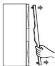
ReplacementRemoval
Speaker Connection Precautions
Read the following before connecting your speakers:
- Y ou can connect speakers with an impedance of 8 ohms or higher. If you use speakers with a lower impedance, and use the amplifier at high volume levels for a long period of time, the built-in protection circuit may be activated.
- Disconnect the power cord from the wall outlet before making any connections.
- Pay close attention to speaker wiring polarity. In other words, connect positive (+) terminals to only positive (+) terminals, and negative (−) terminals to only negative (−) terminals. If you get them the wrong way around, the sound will be out of phase and will sound unnatural.
- Unnecessarily long, or very thin speaker cables may affect the sound quality and should be avoided.
- Be careful not to short the positive and negative wires. Doing so may damage the AV receiver.
- Don't connect more than one cable to each speaker terminal. Doing so may damage the AV receiver.
- Don't connect one speaker to several terminals.
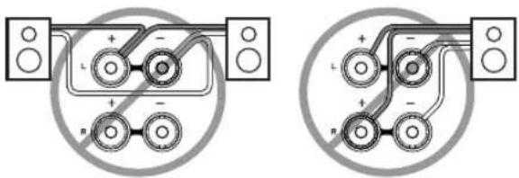
natural_image
Two identical diagrams showing connected components with polarity indicators, no text or symbols present.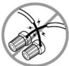
natural_image
Diagram of two cylindrical components with a diagonal line crossing through, enclosed in a circle (no text or symbols)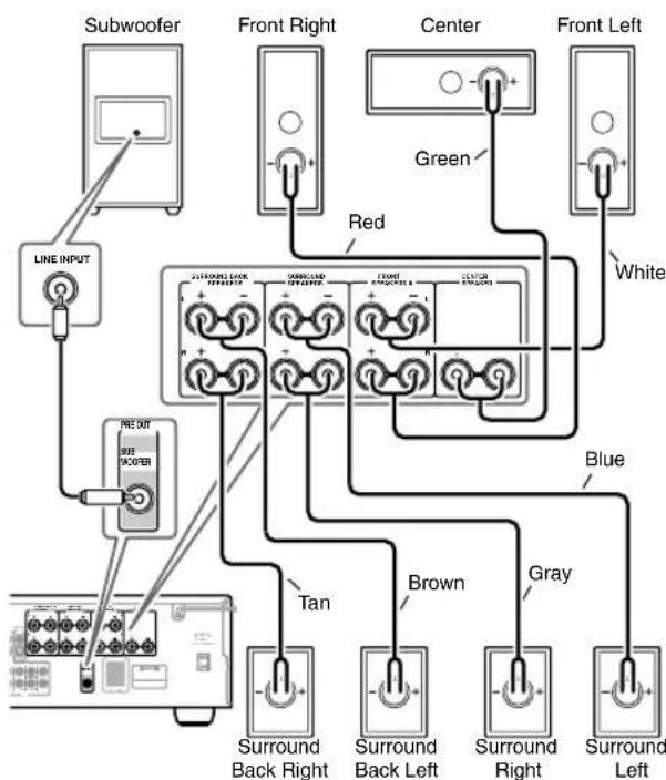
Connecting Speaker Set A
The AV receiver's positive (+) speaker terminals and speaker's positive (+) terminals are color-coded for ease of identification. (The negative (−) speaker terminals are all black.) Match the color of each cable to the corresponding speaker terminal.
| Speaker terminal | Color |
| Front left | White |
| Front right | Red |
| Center | Green |
| Surround left | Blue |
| Surround right | Gray |
| Surround back left | Brown |
| Surround back right | Tan |
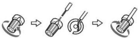
1 On the AV receiver, unscrew the terminal. Fully insert the bare wires. Make sure that the bare wire is touching the inside of the pole. Screw the terminal tight.
natural_image
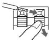
Three-step diagram showing a screwdriver turning a circular component, then rotating (no text or symbols)2 On the speakers, while pressing the terminal lever, insert the wire into the hole, and then release the lever.
3 Using the supplied RCA cable, connect the AV receiver's SUBWOOFER PRE OUT to LINE INPUT on the subwoofer. Make sure the cable is plugged all the way.
Connecting Speaker Set B (sold separately)
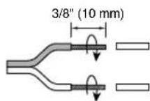
1 Strip 3/8" (10 mm) of insulation from the ends of the speaker cables, and twist the bare wires tightly, as shown.
2 While pressing the lever, insert the wire into the hole, and then release the lever. Make sure that the terminals are gripping the bare wires, not the insulation.
Note:
When speaker set B is turned on, speaker set A is reduced to 5.1-channel playback.
Connecting Antennas
This section explains how to connect the supplied indoor FM antenna and AM loop antenna, and how to connect commercially available outdoor FM and AM antennas. The AV receiver won't pick up any radio signals without any antenna connected, so you must connect the antenna to use the tuner.
Connecting the Indoor FM Antenna
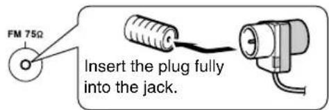
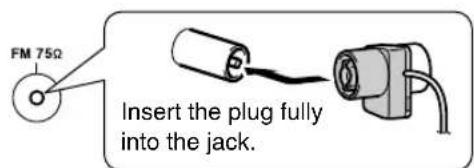
The supplied indoor FM antenna is for indoor use only.
1 Attach the FM antenna, as shown.
■ American Model
■ Other Models
Once your AV receiver is ready for use, you'll need to tune into an FM radio station and adjust the position of the FM antenna to achieve the best possible reception.
2 Use thumbtacks or something similar to fix the FM antenna into position.
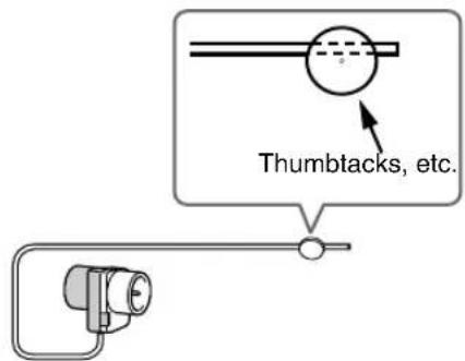
Caution: Be careful that you don't injure yourself when using thumbtacks.
If you cannot achieve good reception with the supplied indoor FM antenna, try a commercially available outdoor FM antenna instead (see page 21).
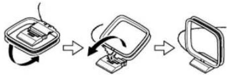
Connecting the AM Loop Antenna
The supplied indoor AM loop antenna is for indoor use only.
1 Assemble the AM loop antenna, inserting the tabs into the base, as shown.
flowchart
graph TD
    A["Start Screen"] --> B["Close-up Display"]
    B --> C["Insert Display"]
    C --> D["Screen with Remote Interface"]
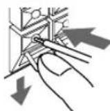
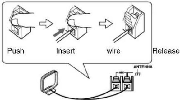
2 Connect both wires of the AM loop antenna to the AM push terminals, as shown.
(The antenna's wires are not polarity sensitive, so they can be connected either way around).
Make sure that the wires are attached securely and that the push terminals are gripping the bare wires, not the insulation.
flowchart
graph LR
    A["Push"] --> B["Insert"]
    B --> C["wire"]
    C --> D["Release"]
    D --> E["Antenna"]
Once your AV receiver is ready for use, you'll need to tune into an AM radio station and adjust the position of the AM antenna to achieve the best possible reception.
Keep the antenna as far away as possible from your AV receiver, TV, speaker cables, and power cords.
If you cannot achieve good reception with the supplied indoor AM loop antenna, try using it with a commercially available outdoor AM antenna (see page 21).
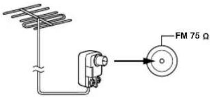
Connecting an Outdoor FM Antenna
If you cannot achieve good reception with the supplied indoor FM antenna, try a commercially available outdoor FM antenna instead.
Notes:
- Outdoor FM antennas work best outside, but usable results can sometimes be obtained when installed in an attic or loft.
- F or best results, install the outdoor FM antenna well away from tall buildings, preferably with a clear line of sight to your local FM transmitter.
- Outdoor antenna should be located away from possible noise sources, such as neon signs, busy roads, etc.
- F or safety reasons, outdoor antenna should be situated well away from power lines and other high-voltage equipment.
- Outdoor antenna must be grounded in accordance with local regulations to prevent electrical shock hazards.
■ Using a TV/FM Antenna Splitter
It's best not to use the same antenna for both FM and TV reception, as this can cause interference problems. If circumstances demand it, use a TV/FM antenna splitter, as shown.
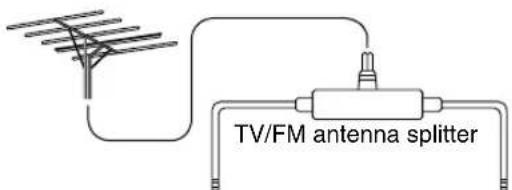
To AV receiver To TV (or VCR)
Connecting an Outdoor AM Antenna
If good reception cannot be achieved using the supplied AM loop antenna, an outdoor AM antenna can be used in addition to the loop antenna, as shown.
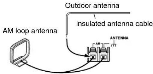
Outdoor AM antennas work best when installed horizontally outside, but good results can sometimes be obtained indoors by mounting horizontally above a window. Note that the AM loop antenna should be left connected.
Outdoor antenna must be grounded in accordance with local regulations to prevent electrical shock hazards.
Connecting Your Components
About AV Connections
- Before making any AV connections, read the manuals supplied with your other AV components.
- Don't connect the power cord until you've completed and double-checked all AV connections.
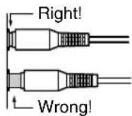
Optical Digital Jacks
The AV receiver's optical digital jacks have shutter-type covers that open when an optical plug is inserted and close when it's removed. Push plugs in all the way.
Caution: To prevent shutter damage, hold the optical plug straight when inserting and removing.
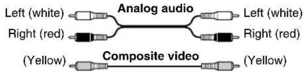
AV Connection Color Coding
RCA-type AV connections are usually color coded: red, white, and yellow. Use red plugs to connect right-channel audio inputs and outputs (typically labeled "R"). Use white plugs to connect left-channel audio inputs and outputs (typically labeled "L"). And use yellow plugs to connect composite video inputs and outputs.
- Push plugs in all the way to make good connections (loose connections can cause noise or malfunctions).
- To prevent interference, keep audio and video cables away from power cords and speaker cables.
AV Cables and Jacks
Video
| Cable Jack Description | |||
| Component video cable | 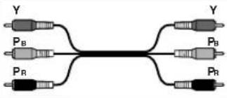 | 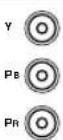 | Component video separates the luminance (Y) and color difference signals (PR, PB), providing the best picture quality. (Some TV manufacturers label their component video jacks slightly differently.) |
| S-Video cable | 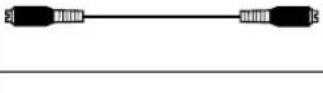 | [SZ5CT] | S-Video separates the luminance and color signals and provides better picture quality than composite video. |
| Composite video cable | ◎ v | Composite video is commonly used on TVs, VCRs, and other video equipment. Use only dedicated composite video cables. | |

Audio
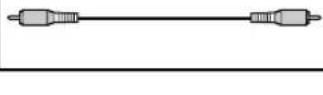
| Cable Jack Description | |||
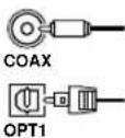
| Optical digital audio cable | 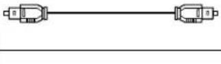 | OPTICAL | This offers the best sound quality and allows you to enjoy Dolby Digital and DTS. The audio quality is the same as for coaxial. |
| Coaxial digital audio cable | 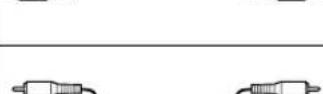 | COA-XIAL | This offers the best sound quality and allows you to enjoy Dolby Digital and DTS. The audio quality is the same as for optical. |
| Analog audio cable (RCA) | 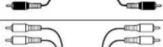 |  | This cable carries analog audio. It's the most common connection format for analog audio and can be found on virtually all AV components. |
| Multichannel analog audio cable (RCA) | 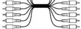 |   | This cable carries multichannel analog audio and is typically used to connect DVD players with a 7.1-channel analog audio output. Several standard analog audio cables can be used instead of a multichannel cable. |
Connecting Audio and Video Signals to the AV Receiver
By connecting both the audio and video outputs of your DVD player and other AV components to the AV receiver, you can switch the audio and video signals simultaneously simply by changing the input source on the AV receiver.
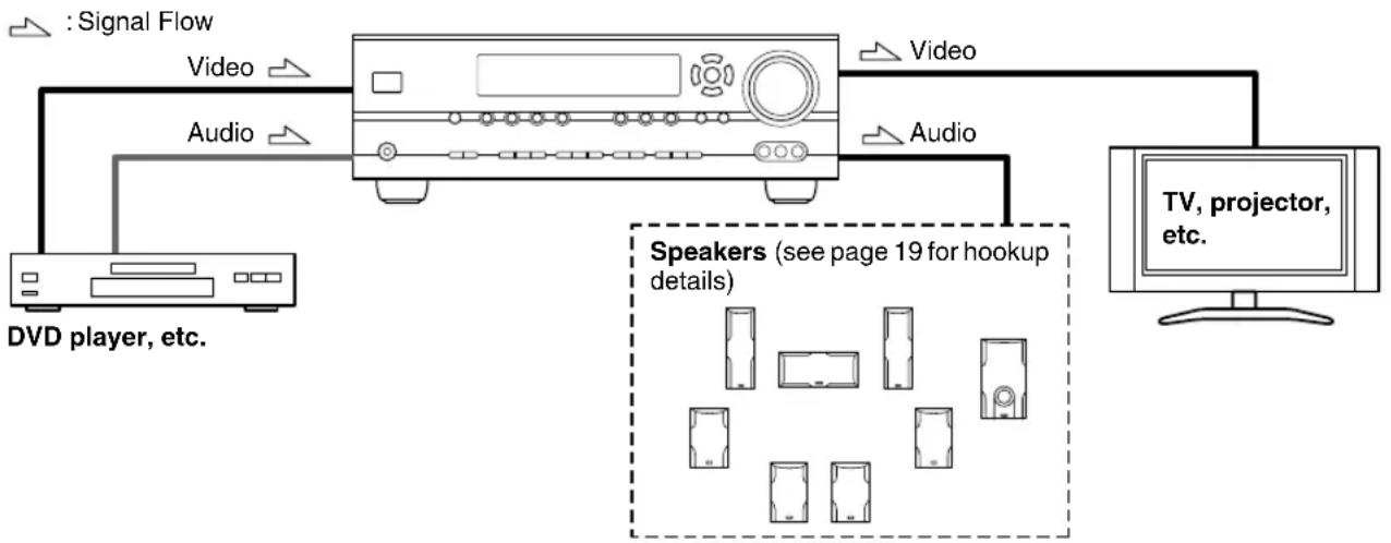
flowchart
graph TD
    A["Signal Flow"] --> B["Video"]
    A --> C["Audio"]
    B --> D["Monitor"]
    C --> D
    D --> E["TV, projector, etc."]
    F["DVD player, etc."] --> B
    G["Speakers (see page 19 for hookup details)"] --> H["Image of Speakers"]
Which Connections Should I Use?
The AV receiver supports several connection formats for compatibility with a wide range of AV equipment. The format you choose will depend on the formats supported by your other components. Use the following sections as a guide. For video components, such as a DVD player, you must make an audio connection and a video connection.
Video Connection Formats
When choosing a connection format, bear in mind that the AV receiver doesn't convert between formats, so only outputs of the same format as the input will output the signal.
Video Signal Flow Chart
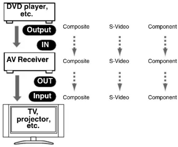
flowchart
graph TD
    A["DVD player, etc."] --> B["Output"]
    B --> C["IN"]
    C --> D["AV Receiver"]
    D --> E["OUT"]
    E --> F["Input"]
    F --> G["TV, projector, etc."]
    style A fill:#f9f,stroke:#333
    style D fill:#f9f,stroke:#333
    style G fill:#ccf,stroke:#333
Audio Connection Formats
When choosing a connection format, bear in mind that the AV receiver doesn't convert between formats. For example, audio signals connected to an OPTICAL or COAXIAL digital input are not output by the analog TAPE OUT, so if you want to record from, for example your CD player, in addition to connecting it to a digital input, you must also connect it to the analog CD IN.
Audio Signal Flow Chart
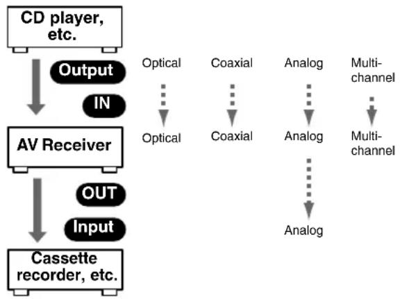
flowchart
graph TD
    A["CD player, etc."] --> B["Output"]
    B --> C["IN"]
    C --> D["AV Receiver"]
    D --> E["OUT"]
    E --> F["Input"]
    F --> G["Cassette recorder, etc."]
    G --> H["Optical"]
    G --> I["Coaxial"]
    G --> J["Analog"]
    G --> K["Multi-channel"]
    H --> L["Optical"]
    I --> M["Coaxial"]
    J --> N["Analog"]
    K --> O["Multi-channel"]
    L --> P["Analog"]
    M --> Q["Analog"]
    N --> R["Analog"]
    O --> S["Analog"]
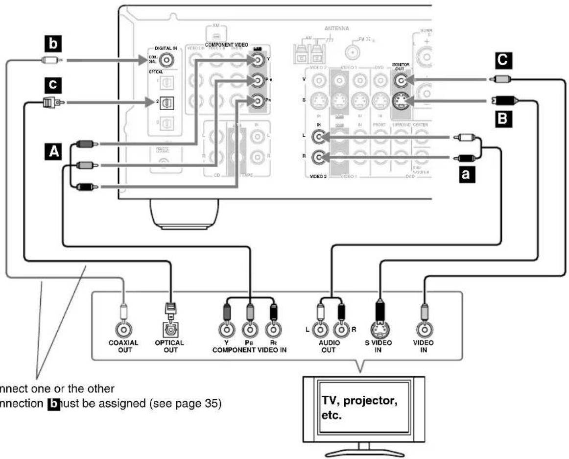
Connecting a TV or Projector
Step 1: Video Connection
Choose a video connection that matches your TV (A, B), a C then make the connection.
Step 2: Audio Connection
Choose an audio connection that matches your TV (a, c), and then make the connection.
- With connection a, you can listen to and record audio from your TV and listen via speaker set B.
• To enjoy Dolby Digital and DTS, use connection b or c. (For recording, use a and b, or a and c.)
Connection AV receiver Signal flow TV Picture quality
| A | COMPONENT VIDEO OUT | Component video input | Best | |
| B | MONITOR OUT S | S-Video input Better | ||
| C | MONITOR OUT V | Composite video input | Standard | |
| a | VIDEO 2 IN L/R | Analog audio L/R output | ||
| b | DIGITAL IN COAXIAL | Digital coaxial output | ||
| c | DIGITAL IN OPTICAL 2 | Digital optical output |
flowchart
graph TD
    subgraph_Component_1["Component Video"]
        A1["AC 2"] -->|a| B1["AC 1"]
        A2["AC 3"] -->|b| B2["AC 4"]
        A3["AC 5"] -->|c| B3["AC 5"]
        A4["AC 6"] -->|d| B4["AC 6"]
    end

    subgraph_Component_2["Antenna"]
        C1["AC 1"] -->|a| B5["AC 2"]
        C2["AC 3"] -->|b| B6["AC 3"]
        C3["AC 4"] -->|c| B7["AC 4"]
        C4["AC 5"] -->|d| B8["AC 5"]
    end

    A1 -->|Differential In| C1
    A2 -->|Differential In| C2
    A3 -->|Differential In| C3
    A4 -->|Differential In| C4

    A1 -->|OPTICAL OUT| C1
    A2 -->|OPTICAL OUT| C2
    A3 -->|OPTICAL OUT| C3

    A1 -->|Y COMPONENT VIDEO IN| C4
    A2 -->|Y COMPONENT VIDEO IN| C5
    A3 -->|Y COMPONENT VIDEO IN| C6

    A1 -->|P B R| C5
    A2 -->|P B R| C6

    A3 -->|P B R| C7

    A1 -->|L AUDIO OUT| C7
    A2 -->|L AUDIO OUT| C8
    A3 -->|L AUDIO OUT| C9

    A1 -->|S VIDEO IN| C8
    A2 -->|S VIDEO IN| C9

    A3 -->|S VIDEO IN| C7

    A1 -->|VIDEO OUT| C7
    A2 -->|VIDEO OUT| C8
    A3 -->|VIDEO OUT| C9

    A1 -->|TV, projector, etc.| C7
    A2 -->|TV, projector, etc.| C8
    A3 -->|TV, projector, etc.| C9

    style Component_1 fill:#f9f,stroke:#333
    style Component_2 fill:#ccf,stroke:#333
    style Component_3 fill:#cfc,stroke:#333
    style Component_4 fill:#fcc,stroke:#333
    style Component_5 fill:#cff,stroke:#333
    style Component_6 fill:#ffc,stroke:#333
    style Component_7 fill:#cfc,stroke:#333
    style Component_8 fill:#fcc,stroke:#333
    style Component_9 fill:#ffc,stroke:#333

If your TV has no audio outputs, connect an audio output from your VCR or cable or satellite receiver to the AV receiver and use its tuner to listen to TV programs through the AV receiver (see pages 27 and 29).
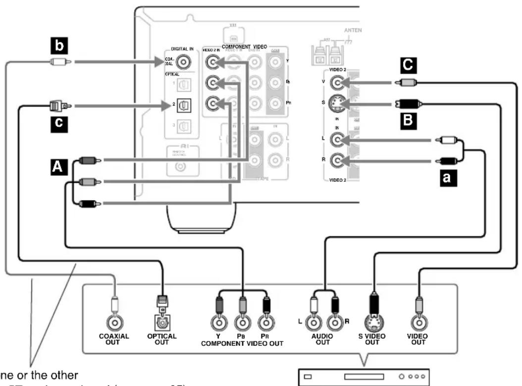
Connecting a DVD player
Step 1: Video Connection
Choose a video connection that matches your DVD player (A, C), and then make the connection. You must connect the AV receiver to your TV via the same type of connection.
Step 2: Audio Connection
Choose an audio connection that matches your DVD player (a, b), ac then make the connection.
- With connection a, you can listen to and record audio from a DVD and listen via speaker set B.
- To enjoy Dolby Digital and DTS, use connection b or c. (For recording, use a and b, or ■ and ■.)
- If your DVD player has main left and right outputs and multichannel left and right outputs, be sure to use the main left and right outputs for connection a
Connection AV receiver Signal flow DVD player Picture quality
| A | COMPONENT VIDEO DVD IN | Component video output | Best | |
| B | DVD IN S | S-Video output Better | ||
| C | DVD IN V | Composite video output | Standard | |
| a | DVD IN FRONT | Analog audio L/R output | ||
| b | DIGITAL IN COAXIAL | Digital coaxial output | ||
| c | DIGITAL IN OPTICAL 1 | Digital optical output |

flowchart
graph TD
    subgraph Component_1
        A["Component 1"] --> B["VIDEO 2"]
        B --> C["VIDEO 1"]
        C --> D["ANTenna"]
    end
    subgraph Component_2
        E["Component 2"] --> F["VIDEO 2"]
        F --> G["VIDEO 1"]
        G --> H["Antenna"]
    end
    subgraph Video_1
        I["Video 1"] --> J["VIDEO 2"]
        K["Video 2"] --> L["VIDEO 1"]
        M["Audio 1"] --> N["VIDEO 2"]
        O["S VIDEO 1"] --> P["VIDEO 2"]
        Q["Video 1"] --> R["VIDEO 2"]
    end
    subgraph Video_2
        S["Video 2"] --> T["VIDEO 1"]
        U["Audio 2"] --> V["VIDEO 1"]
        W["Video 2"] --> X["VIDEO 1"]
        Y["Video 2"] --> Z["VIDEO 1"]
    end
    subgraph Audio_1
        AA["Audio 1"] --> AB["VIDEO 2"]
        AC["Video 1"] --> AD["VIDEO 2"]
        AE["Audio 2"] --> AF["VIDEO 1"]
        AG["Video 2"] --> AH["VIDEO 1"]
    end
    subgraph Video_3
        AI["Video 3"] --> AJ["VIDEO 2"]
        AK["Audio 3"] --> AL["VIDEO 1"]
        AM["Video 3"] --> AN["VIDEO 1"]
        AO["Audio 3"] --> AP["VIDEO 1"]
    end
    subgraph Audio_4
        AQ["Audio 4"] --> AR["VIDEO 2"]
        AS["Video 4"] --> AT["VIDEO 1"]
        AU["Audio 4"] --> AV["VIDEO 2"]
        AW["Video 4"] --> AX["VIDEO 1"]
    end
    subgraph Audio_5
        AZ["Audio 5"] --> BA["VIDEO 2"]
        BB["Video 5"] --> BC["VIDEO 1"]
        BD["Audio 5"] --> BE["VIDEO 2"]
        BF["Video 5"] --> BG["VIDEO 1"]
    end
    subgraph Video_6
        BH["Video 6"] --> BI["VIDEO 2"]
        BJ["Audio 6"] --> BK["VIDEO 1"]
        BL["Video 6"] --> BM["VIDEO 1"]
        BN["Audio 6"] --> BO["VIDEO 2"]
    end
    subgraph Audio_7
        BP["Audio 7"] --> BQ["VIDEO 2"]
        BR["Video 7"] --> BS["VIDEO 1"]
        BT["Audio 7"] --> BU["VIDEO 2"]
        BV["Video 7"] --> BW["VIDEO 1"]
    end
    subgraph Video_8
        BX["Audio 8"] --> BY["VIDEO 2"]
        BZ["Video 8"] --> CA["VIDEO 1"]
        CB["XM"] --> CC["XM"]
    end
    subgraph Audio_9
        CD["XM"] --> CE["XM"]
    end
    subgraph Audio_10
        CF["XM"] --> CG["XM"]
    end
    subgraph Audio_11
        CH["XM"] --> CI["XM"]
    end
    subgraph Audio_12
        CJ["XM"] --> CK["XM"]
    end
Connect one or the other
Connection must be assigned (see page 35)
To connect a DVD player or DVD-Audio/SACD-capable player with a multichannel analog audio output, see page 26.
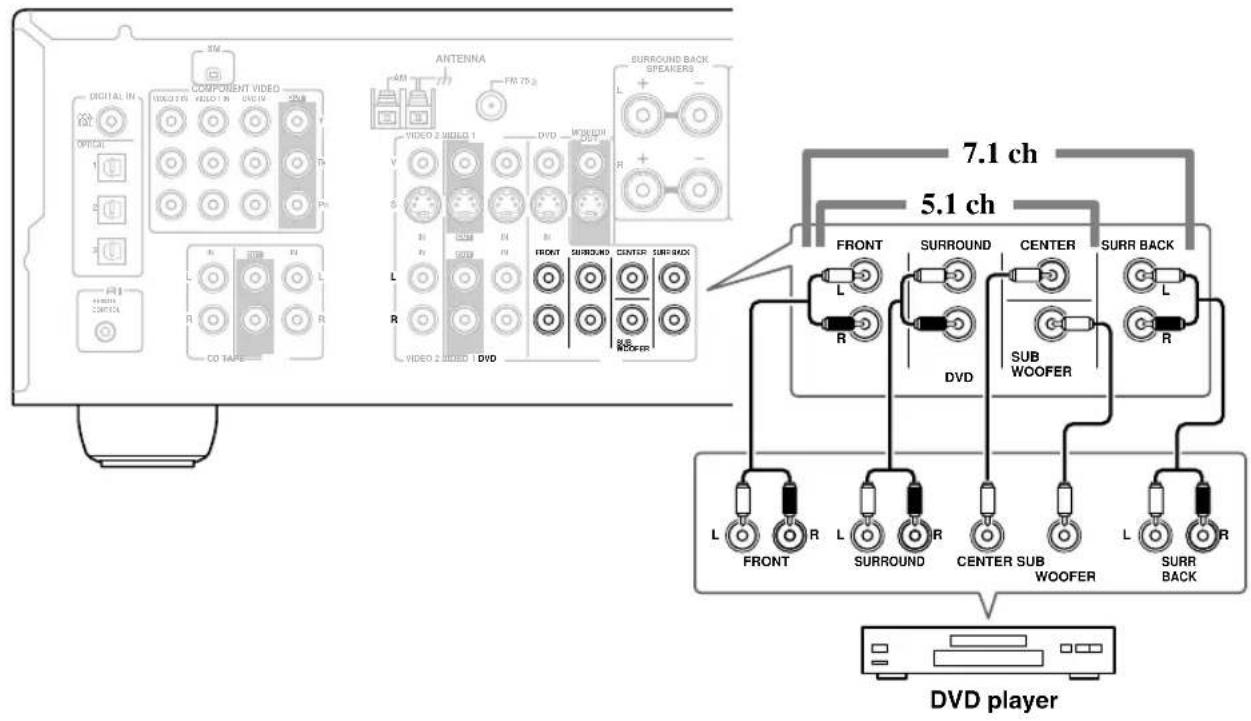
Hooking Up the Multichannel DVD Input
If your DVD player supports multichannel audio formats such as DVD-Audio or SACD, and it has a multichannel analog audio output, you can connect it to the AV receiver's multichannel DVD input. Use a multichannel analog audio cable, or several normal audio cables, to connect the AV receiver's DVD IN FRONT L/R, CENTER, SURROUND L/R, SURR BACK L/R, and SUBWOOFER jacks to the 7.1-channel analog audio output on your DVD player. If your DVD player has a 5.1-channel analog audio output, don't connect anything to the AV receiver's SURR BACK L/R jacks.
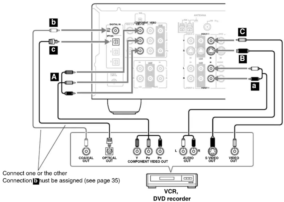
Connecting a VCR or DVD Recorder for Playback

With this hookup, you can use your VCR's tuner to listen to your favorite TV programs via the AV receiver, useful if your TV has no audio outputs.
Step 1: Video Connection
Choose a video connection that matches your VCR or DVD recorder (A, B, C), and then make the connection. You must connect the AV receiver to your TV via the same type of connection.
Step 2: Audio Connection
Choose an audio connection that matches your VCR or DVD recorder (a, b), a then make the connection.
- With connection a, you can listen to the VCR or DVD recorder even via speaker set B.
- To enjoy Dolby Digital and DTS, use connection b or b. (To listen via speaker set B, use ■ and ■, or ■ and c.)
Connection AV receiver Signal flow VCR or DVD recorder Picture quality
| A | COMPONENT VIDEO VIDEO 1 IN | Component video output | Best | |
| B | VIDEO 1 IN S | S-Video output Better | ||
| C | VIDEO 1 IN V | Composite video output | Standard | |
| a | VIDEO 1 IN L/R | Analog audio L/R output | ||
| b | DIGITAL IN COAXIAL | Digital coaxial output | ||
| c | DIGITAL IN OPTICAL 1 | Digital optical output |
flowchart
graph TD
    subgraph_Component_1["Component 1"]
        A["AC"] --> B["Digital IN"]
        C["AC"] --> D["Optical"]
        E["A"] --> F["Connect one or the other"]
        G["XT"] --> H["VIDEO OUT"]
        I["XT"] --> J["VIDEO OUT"]
        K["XT"] --> L["VIDEO OUT"]
    end

    subgraph_Component_2["Component 2"]
        M["XT"] --> N["VIDEO OUT"]
        O["XT"] --> P["VIDEO OUT"]
        Q["XT"] --> R["VIDEO OUT"]
        S["XT"] --> T["VIDEO OUT"]
    end

    subgraph_Antenna["Antenna"]
        U["XT"] --> V["VIDEO OUT"]
        W["XT"] --> X["VIDEO OUT"]
        Y["XT"] --> Z["VIDEO OUT"]
        AA["XT"] --> AB["VIDEO OUT"]
    end

    B --> AC["COAXIAL OUT"]
    D --> AD["OPTICAL OUT"]
    E --> AE["Y COMPONENT VIDEO OUT"]
    F --> AF["L AUDIO OUT"]
    G --> AG["S VIDEO OUT"]
    H --> AH["VIDEO OUT"]

    subgraph_VCR["VCR, DVD recorder"]
        AI["AC"] --> AJ["Coaxial Out"]
        AK["AC"] --> AL["Optical Out"]
        AM["AC"] --> AN["COMPONENT VIDEO OUT"]
        AO["AC"] --> AP["PB PR"]
        AQ["AC"] --> AR["L Audio OUT"]
        AS["AC"] --> AT["S VIDEO OUT"]
        AU["AC"] --> AV["VIDEO OUT"]
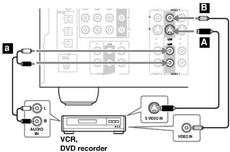
Connecting a VCR or DVD Recorder for Recording
Step 1: Choose a video connection that matches your VCR or DVD recorder (A or B), and then make the connection. The video source to be recorded must be connected to the AV receiver via the same type of connection.
Step 2: Make the audio connection a.
flowchart
graph TD
    A["Audio IN"] -->|L| B["VCR, DVD recorder"]
    C["Video IN"] -->|S| B
    D["Video 1"] -->|B| B
    E["Video 2"] -->|A| B
    F["Video 3"] -->|B| B
    G["Video 4"] -->|A| B
    H["Video 5"] -->|B| B
    I["Video 6"] -->|A| B
    J["Video 7"] -->|B| B
    K["Video 8"] -->|A| B
    L["Audio IN"] --> M["+"]
    N["Video IN"] --> O["+"]
    P["Video 9"] --> Q["+"]
Connection AV receiver Signal flow VCR or DVD recorder Picture quality
| A | VIDEO 1 OUT S | S-Video input Better | |
| B | VIDEO 1 OUT V | Composite video input Standard | |
| a | VIDEO 1 OUT L/R | Analog audio L/R input — |
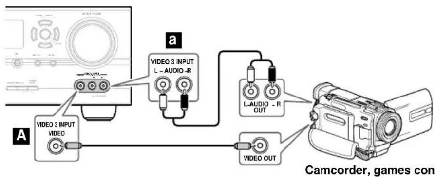
Connecting a Camcorder, Games Console, or Other Device
Step 1: Make the video connection A.
Step 2: Make the audio connection a.
flowchart
graph TD
    A["Computer"] -->|a| B["VIDEO 3 INPUT VIDEO"]
    A -->|a| C["L-AUDIO -R OUT"]
    A -->|A| D["VIDEO OUT"]
    B --> E["Camcorder, games con"]
Connection AV receiver Signal flow Camcorder or console
| A | VIDEO 3 INPUT | Composite video output | |
| a | VIDEO 3 INPUT L/R | Analog audio L/R output |
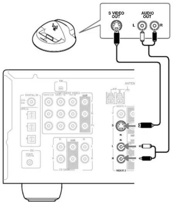
Connecting a Satellite, Cable, Set-top box, or Other Video Source

With this hookup, you can use your satellite or cable receiver to listen to your favorite TV programs via the AV receiver, useful if your TV has no audio outputs.
Step 1: Video Connection
Choose a video connection that matches the video source (A, B C), and then make the connection. You must connect the AV receiver to your TV via the same type of connection.
Step 2: Audio Connection
Choose an audio connection that matches the video source (a, c), a then make the connection.
- With connection a, you can listen to and record audio from the video source and listen via speaker set B.
- To enjoy Dolby Digital and DTS, use connection b or c. (For recording, use a and b or ■ and ■.)
Connection AV receiver Signal flow Video source Picture quality
| A | COMPONENT VIDEO VIDEO 2 IN | Component video output Best | |
| B | VIDEO 2 IN S | S-Video output Better | |
| C | VIDEO 2 IN V | Composite video output Standard | |
| a | VIDEO 2 IN L/R | Analog audio L/R output | |
| b | DIGITAL IN COAXIAL | Digital coaxial output | |
| c | DIGITAL IN OPTICAL 2 | Digital optical output |
flowchart
graph TD
    subgraph_Component_1["Component Video"]
        A1["Coaxial OUT"] --> B1["OPTICAL OUT"]
        B1 --> C1["Y COMPONENT VIDEO OUT"]
        C1 --> D1["L AUDIO OUT"]
        D1 --> E1["S VIDEO OUT"]
        E1 --> F1["VIDEO OUT"]
    end
    subgraph_Component_2["Component Video"]
        A2["COAL OUT"] --> B2["OPTICAL OUT"]
        B2 --> C2["Y COMPONENT VIDEO OUT"]
        C2 --> D2["L AUDIO OUT"]
        D2 --> E2["S VIDEO OUT"]
        E2 --> F2["VIDEO OUT"]
    end
    subgraph_Component_3["Component Video"]
        A3["A"] --> B3["OPTICAL OUT"]
        B3 --> C3["Y COMPONENT VIDEO OUT"]
        C3 --> D3["L AUDIO OUT"]
        D3 --> E3["S VIDEO OUT"]
        E3 --> F3["VIDEO OUT"]
    end
    subgraph_Antenna_1["Antenna"]
        A4["C"] --> B4["OPTICAL OUT"]
        B4 --> C4["Y COMPONENT VIDEO OUT"]
        C4 --> D4["L AUDIO OUT"]
        D4 --> E4["S VIDEO OUT"]
        E4 --> F4["VIDEO OUT"]
    end
    subgraph_Antenna_2["Antenna"]
        A5["B"] --> B6["OPTICAL OUT"]
        B6 --> C6["Y COMPONENT VIDEO OUT"]
        C6 --> D6["L AUDIO OUT"]
        D6 --> E6["S VIDEO OUT"]
        E6 --> F6["VIDEO OUT"]
    end
    subgraph_Antenna_3["Antenna"]
        A7["C"] --> B8["OPTICAL OUT"]
        B8 --> C8["Y COMPONENT VIDEO OUT"]
        C8 --> D8["L AUDIO OUT"]
        D8 --> E8["S VIDEO OUT"]
        E8 --> F8["VIDEO OUT"]
Connect one or the other
Connection must be assigned (see page 35)
Satellite, cable, set-top box, etc.
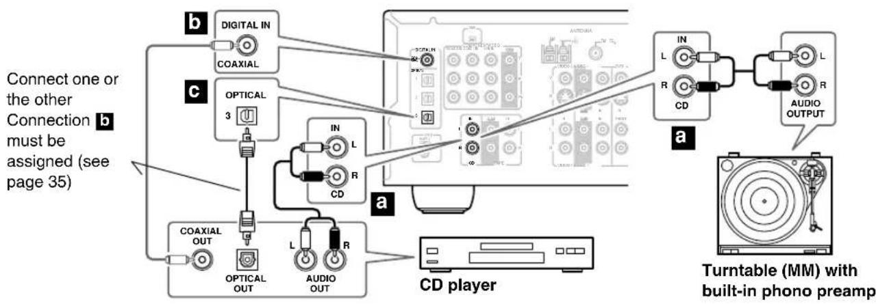
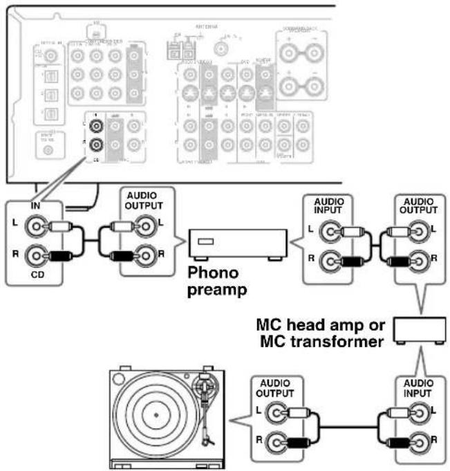
Connecting a CD Player or Turntable
■ CD Player or Turntable (MM) with Built-in Phono Preamp
Step 1:
Choose a connection that matches your CD player (a, ■). Use connection for a burntable with a built-in phono preamp.
flowchart
graph TD
    A["CD player"] --> B["OPTICAL OUT"]
    A --> C["AUDIO OUT"]
    A --> D["COAXIAL OUT"]
    A --> E["OPTICAL 3"]
    A --> F["IN L R CD"]
    A --> G["DIGITAL IN COAXIAL"]
    H["Turntable (MM) with built-in phono preamp"] --> I["IN L R CD"]
    H --> J["AUDIO OUTPUT"]
    style A fill:#f9f,stroke:#333
    note1["Connect one or the other Connection b must be assigned (see page 35)"]
    note2["a"]
    note3["b"]
    note4["c"]
    note5["d"]
    note6["e"]
    note7["f"]
    note8["g"]
    note9["h"]
    note10["i"]
    note11["j"]
    note12["k"]
    note13["l"]
    note14["m"]
    note15["n"]
    note16["o"]
    note17["p"]
    note18["q"]
    note19["r"]
    note20["s"]
    note21["t"]
    note22["u"]
    note23["v"]
    note24["w"]
    note25["x"]
    note26["y"]
    note27["z"]
    note28["a"]
    note29["a"]
    note30["b"]
    note31["c"]
    note32["d"]
    note33["e"]
    note34["f"]
    note35["g"]
    note36["h"]
    note37["i"]
    note38["j"]
    note39["k"]
    note40["l"]
    note41["m"]
    note42["n"]
    note43["o"]
    note44["p"]
    note45["q"]
    note46["r"]
    note47["s"]
    note48["t"]
    note49["u"]
    note50["w"]
    note51["x"]
    note52["y"]
    note53["z"]
    note54["a"]
    note55["a"]
    note56["b"]
    note57["c"]
    note58["d"]
    note59["e"]
    note60["f"]
    note61["g"]
    note62["h"]
    note63["i"]
    note64["j"]
    note65["k"]
    note66["l"]
    note67["m"]
    note68["n"]
    note69["o"]
    note70["p"]
    note71["q"]
    note72["r"]
    note73["s"]
    note74["t"]
    note75["u"]
    note76["w"]
    note77["x"]
    note78["y"]
    note79["z"]
    note80["a"]
    note81["a"]
    note82["a"]
    note83["b"]
    note84["c"]
    note85["d"]
    note86["e"]
    note87["f"]
    note88["g"]
    note89["h"]
    note90["i"]
    note91["j"]
    note92["k"]
    note93["l"]
    note94["m"]
    note95["n"]
    note96["o"]
    note97["p"]
    note98["q"]
    note99["r"]
    note100["s"]
- With connection a, you can listen to and record audio from your CD player or turntable and listen via speaker set B.
• To connect the CD player digitally, use connection b or c. (For recording, use a and b, or a and c.)
Connection AV receiver Signal flow CD or turntable
| a | CD IN L/R | ⇐ | Analog audio L/R output |
| b | DIGITAL IN COAXIAL | ⇐ | Digital coaxial output |
| c | DIGITAL IN OPTICAL 3 | ⇐ | Digital optical output |
■ Turntable (MM) with no Phono Preamp Built-in
A phono preamp is necessary to connect a turntable that doesn't have a phono preamp built-in.
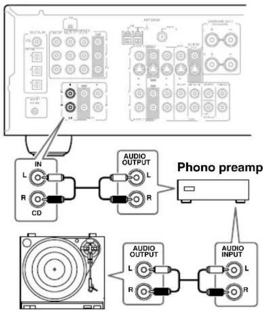
flowchart
graph TD
    A["PC Computer"] --> B["IN L R CD"]
    B --> C["AUDIO OUTPUT L R"]
    C --> D["Phono preamp"]
    D --> E["AUDIO OUTPUT L R"]
    E --> F["AUDIO INPUT L R"]
■ Turntable with an MC (Moving Coil) Cartridge
An MC head amp and phono preamp are necessary to connect a turntable with an MC (Moving Coil) cartridge.
flowchart
graph TD
    A["PC Computer"] --> B["IN L R CD"]
    B --> C["Phono preamp"]
    C --> D["AUDIO OUTPUT L R"]
    D --> E["AUDIO INPUT L R"]
    E --> F["MC head amp or MC transformer"]
    F --> G["AUDIO OUTPUT L R"]
    G --> H["AUDIO INPUT L R"]
    H --> I["Output"]
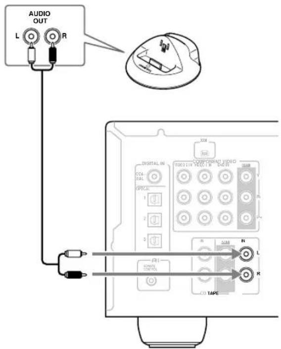
Connecting an HDD-compatible Component
As of this printing, the Onkyo Remote Interactive Dock is the only HDD-compatible component available.
■ For HDD-compatible components that support video
Connect your HDD-compatible component's analog audio output jacks and S-Video output jack to the AV receiver's VIDEO 2 IN L/R jacks and VIDEO 2 IN S jack.
■ For HDD-compatible components that don't support video
Connect your HDD-compatible component's analog audio output jacks to the AV receiver's TAPE IN L/R jacks.
Notes:
- Connect the Remote Interactive Dock with an A ple (see page 33).
- Set the Remote Interactive Dock's RI MODE switch to HDD.
- Set the AV receiver's Input Display to HDD (see page 35).
- Refer to the Remote Interactive Dock's instruction manual.
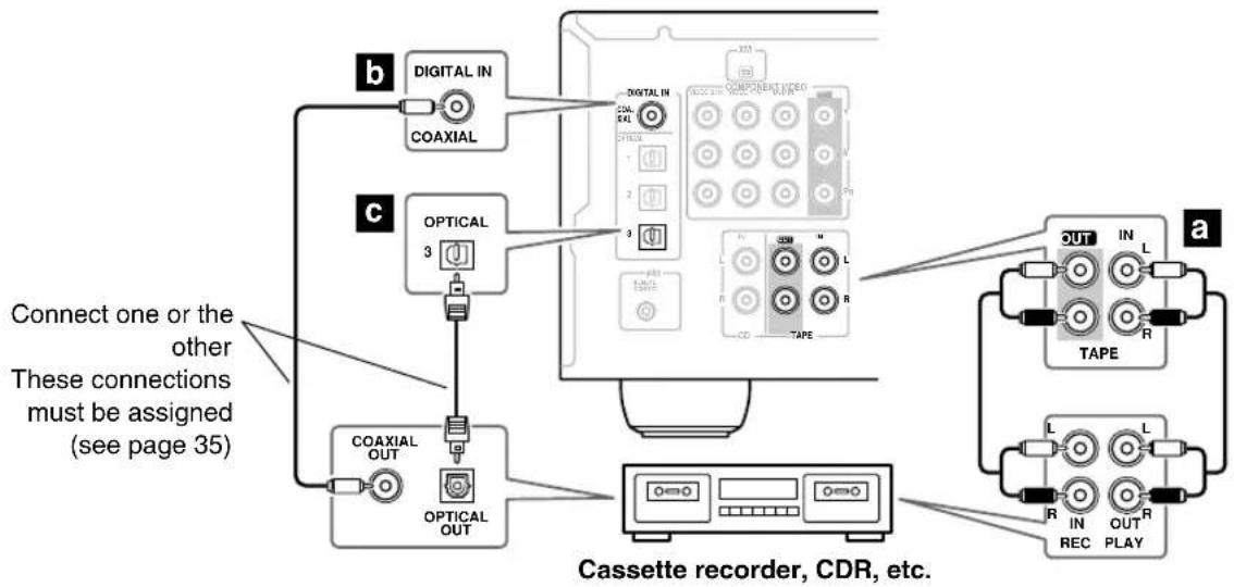
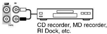
Connecting a Cassette, CDR, MiniDisc, or DAT Recorder
Step 1:
Choose a connection that matches the recorder (a, ■), then make the connection.
flowchart
graph TD
    A["Cassette recorder, CDR, etc."] --> B["Coaxial OUT"]
    A --> C["OPTICAL 3"]
    A --> D["OPTICAL OUT"]
    A --> E["COAXIAL IN COAXIAL"]
    A --> F["COMPONENT VIDEO"]
    F --> G["OUT L IN TAPE"]
    F --> H["R OUT R REC PLAY"]
    style A fill:#f9f,stroke:#333
    style B fill:#ccf,stroke:#333
    style C fill:#cfc,stroke:#333
    style D fill:#fcc,stroke:#333
    style E fill:#cff,stroke:#333
    style F fill:#ffc,stroke:#333
    style G fill:#cfc,stroke:#333
    style H fill:#fcc,stroke:#333
- With connection a, you can listen via speaker set B.
• T o connect the recorder digitally, use connection a and abr d.
Connection AV receiver Signal flow Cassette/CDR/MD/DAT recorder
| a | TAPE IN L/R | ⇐ | Analog audio L/R output |
| TAPE OUT L/R | ⇒ | Analog audio L/R input | |
| b | DIGITAL IN COAXIAL | ⇐ | Digital coaxial output |
| c | DIGITAL IN OPTICAL 3 | ⇐ | Digital optical output |
Connecting the Power Cord of Another Component
The AV receiver has an AC outlet on its rear panel for connecting the power cord of another AV component. The other component's power switch can then be left in the ON position so that it turns on or off when the AV receiver is set to On or Standby.
Caution:
• Make sure that the capacity of the component that you connect to the AC OUTLET does not exceed the stated capacity (e.g., 100 W).
Notes:
- Onkyo components connected via should be connected directly to a wall outlet, not the AV receiver's AC OUTLET.
- The socket type and capacity depends on the country in which you purchased the AV receiver.
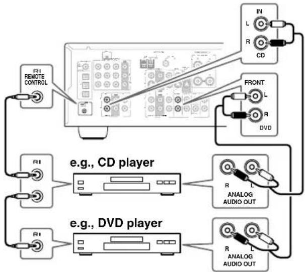
Connecting Onkyo Components
Step 1: Make sure that each Onkyo component is connected to the AV receiver with an analog audio cable (connection a) in the hookup examples) (see pages 24 to 32).
Step 2: Make the connection.
Step 3: If you're using an MD, CDR, or HDD component, change the input Display (see page 35).
With Remote Interactive), you can use the following special functions:
■ Auto Power On/Standby
When you start playback on a component connected via if the AV receiver is on Standby, it will automatically turn on and select that component as the input source. Similarly, when the AV receiver is set to Standby, all components connected via will also go on Standby. This function will not work on components connected to an AC OUTLET on the AV receiver.
■ Direct Change
When playback is started on a component connected via the AV receiver automatically selects that component as the input source. If your DVD player is connected to the AV receiver's multichannel DVD input, you'll need to press the [MULTI CH] button to hear all channels (see page 37), as the Direct Change function only selects the FRONT DVD IN jacks.
■ Remote Control
You can use the AV receiver's remote controller to control your other RI-capable Onkyo components, pointing the remote controller at the AV receiver's remote control sensor instead of the component. You must enter the appropriate remote control code first (page 59).
Notes:
- Use only Rables for connections. cables are supplied with Onkyo players (DVD, CD, etc.).
- Some components have two Racks. You can connect either one to the AV receiver. The other jack is for connecting additional Rapable components.
- Connect only Onkyo components to iRoks. Connecting other manufacturer's components may cause a malfunction.
- Some components may not support all functions. Refer to the manuals supplied with your other Onkyo components.
flowchart
graph TD
    A["RI REMOTE CONTROL"] --> B["CD Player"]
    C["RI"] --> D["CD Player"]
    E["RFONT"] --> F["RFID"]
    G["DVD"] --> H["RFID"]
    I["e.g., CD player"] --> J["Analog Audio Out"]
    K["e.g., DVD player"] --> L["Analog Audio Out"]
    B --> M["In R CD"]
    F --> N["R"]
    H --> O["R"]
    J --> P["R"]
    L --> Q["R"]
Connecting the Power Cord
- Connect the AV receiver's and subwoofer's power cord to a suitable wall outlet.
Notes:
- Before connecting the power cord, connect all of your speakers and AV components.
- Turning on the AV receiver and subwoofer may cause a momentary power surge that might interfere with other electrical equipment on the same circuit. If this is a problem, plug the AV receiver into a different branch circuit.
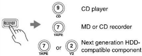
Turning On and Standby
1
AV receiver

Remote controller
ON:STANDBY

Press the [STANDBY/ON] button.
Alternatively, press the remote controller's [RECEIVER] button, followed by the [ON/STANDBY] button.
The AV receiver comes on, the display lights up, and the STANDBY indicator goes off.
To turn the AV receiver off, press the [STANDBY/ON] button, or press the remote controller's [ON/STANDBY] button. The AV receiver will enter Standby mode. To prevent any loud surprises when you next turn on the AV receiver, always turn down the volume before you turn it off.
To turn on the subwoofer, press its [POWER] switch to the ON position (not North American models).
Smooth Operation in a Few Easy Steps
To ensure smooth operation, here's a few easy steps to help you configure the AV receiver before you use it for the very first time. These settings only need to be made once.
■ Have you connected a component to a digital audio input?
If you have, see "Assigning Digital Inputs to Input Sources" on page 35.
■ Have you connected an Onkyo MD recorder, CD recorder, or next generation HDD-compatible component?
If you have, see "Changing the Input Display" on page 35.
Testing the speakers
To test that all of the speakers are working properly, press the remote controller's [TEST TONE] button. The test tone will be output by each speaker in turn and the name of each speaker will appear on the display. To turn off the test tone, press the [TEST TONE] button again.
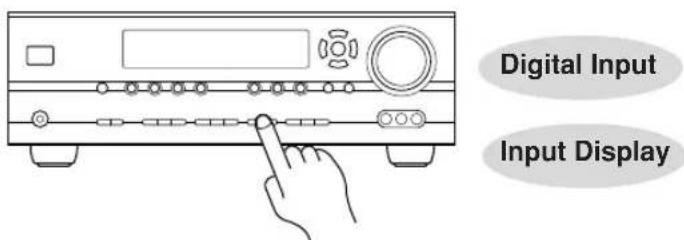
- If the test tone is not produced by a speaker, or it's produced by a speaker other than that shown on the display, you may have wired the speakers incorrectly and you should check your connections (see page 19).
- Testing cannot be performed while speaker set B is on or a pair of headphones is connected.
Assigning Digital Inputs to Input Sources
To enjoy Dolby Digital and DTS, you must connect your DVD player to the AV receiver digitally (coaxial or optical).
Here are the default assignments.
| Input selector Default assignment | |
| DVD COAX | |
| VIDEO 1 OPT 1 | |
| VIDEO 2 OPT 2 | |
| VIDEO 3 - - - | |
| TAPE - - - | |
| CD OPT 3 | |
With this function, you can change the digital inputs assign. If, for example, you connect your DVD player to the DIGITAL IN OPTICAL 1 input (OPT1), you'll need to assign it to the DVD input source, as follows.
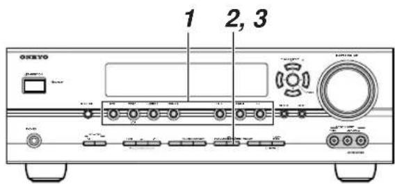
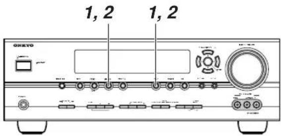
| 1 | Press the input selector button for the input source that you want to assign.(Digital inputs cannot be assigned to the TUNER input source.) |
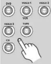 | |
2 DIGITAL INPUT | Press the [DIGITAL INPUT] button.The current assignment appears. |
| DVD : COAX | |
3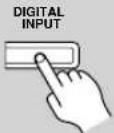 | Press the [DIGITAL INPUT] button repeatedly to select COAX, OPT1, OPT2, OPT3, or “- - - -” (analog). |
| DVD : OPT1 |
1
2
3
Note:
Make sure that components connected digitally are configured to output digital audio. Refer to the relevant manuals.
Changing the Input Display
If you connect an Rapable Onkyo MiniDisc recorder, CD recorder or next generation HDD-compatible component to the TAPE IN/OUT or VIDEO 2 IN jacks, for RDI work properly, you must change this setting.
This setting can only be changed on the AV receiver.
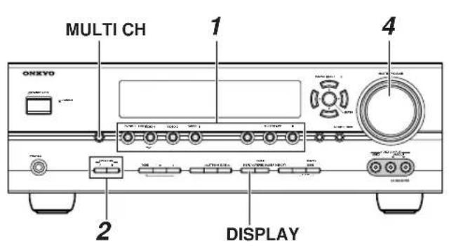
1

Press the [TAPE] or [VIDEO 2] input selector button so that "TAPE" or "VIDEO2" appears on the display.
TAPE
VIDEO2
2

Press and hold down the [TAPE] or [VIDEO 2] input selector button (about 3 seconds) to change the setting.
Repeat this step to select MD, CDR, or HDD.
For the TAPE input selector, the setting changes in this order:
TAPE→MD→CDR→HDD
↑
For the VIDEO 2 input selector, the setting changes in this order:
VIDEO 2↔ HDD
Note:
HDD can be selected for the TAPE input selector or VIDEO 2 input selector, but not both at the same time.
Basic AV Receiver Operation
Subwoofer's rear panel
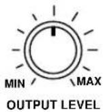
| 1AV receiver | Remote controller | Use the AV receiver's input selector buttons to select the input source.To select the input source with the remote controller, press the [RECEIVER] REMOTE MODE button, and then use the INPUT SELECTOR buttons.On the remote controller, the [V1], [V2], and [V3] buttons select the VIDEO 1,VIDEO 2, and VIDEO 3 input sources respectively. |
2AV receiver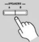 | Remote controller | To turn the speakers on or off, use the AV receiver's SPEAKERS [A] and [B] buttons, or use the remote controller's [SP A/B] button.Pressing the remote controller's [SP A/B] button cycles through the following settings:Speaker Set A → Speaker Set A&B → Speaker Set B → Off.Note that while speaker set B is on,speaker set A is reduced to 5.1-channel playback.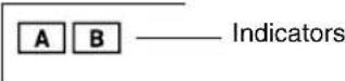 See page 5 for more information about speaker sets A and B. See page 5 for more information about speaker sets A and B. |
| 3 | Start playback on the source component.To watch a DVD or other video source, on your TV, select the video input that's connected to the AV receiver's MONITOR OUT jack. | |
4AV receiver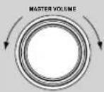 | Remote controller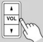 | To adjust the volume, use the MASTER VOLUME control, or the remote controller's [VOL] button.The volume can be set to MIN, 1 through 79, or MAX. Since the AV receiver is designed for home theater enjoyment, it has a wide volume range for precise adjustment.To set the level of the subwoofer, use the OUTPUT LEVEL control.Because our ears are less sensitive to very low bass sounds, there's a temptation to set the level of the subwoofer too high. As a rule of thumb, set the subwoofer level to what you think is the optimal level, and then back it off slightly. |
| 5 | Select a suitable listening mode and enjoy!See “Using the Listening Modes” on page 46. |
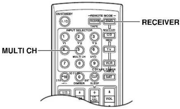
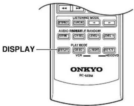
Using the Multichannel DVD Input
The multichannel DVD input is for connecting a component with a 7.1-channel analog audio output, such as a DVD-Audio or SACD-capable DVD player, or an MPEG decoder. See page 26 for hookup information.
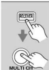
Press the [RECEIVER] REMOTE MODE button, followed by the [MULTI CH] button.
The MULTI CH indicator appears on the display.
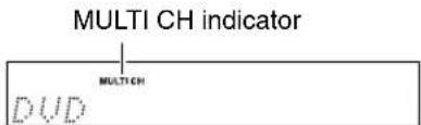
Audio from the multichannel DVD input will now be used for the DVD input source.
Note:
- While the multichannel DVD input is selected, the Speaker Configuration settings on page 54 are ignored, and signals from the multichannel input are fed to the speakers as they are.
Displaying Source Information
You can display various information about the current input source as follows.
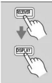
Press the [RECEIVER] REMOTE MODE button, and then press the [DISPLAY] button repeatedly to cycle through the available information.
The following information can typically be displayed:
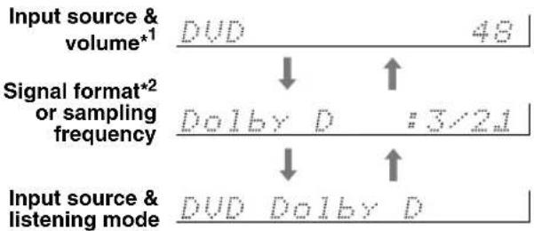
flowchart
graph TD
    A["Input source & volume*1"] --> B["DUD"]
    B --> C["48"]
    D["Signal format*2 or sampling frequency"] --> E["Dolby D"]
    E --> F[":3/21"]
    G["Input source & listening mode"] --> H["DUD"]
    H --> I["Dolby D"]
    I --> J["↑"]
*1 When AM or FM radio is used, the band, preset number, and frequency are displayed.
*2 If the input signal is analog, or AM or FM radio is selected, no format information is displayed. If the input signal is PCM, the sampling frequency is displayed. If the input signal is digital but not PCM, the signal format is displayed. Information is displayed for about 3 seconds, then the previous display reappears.
Note:
- The listening mode is displayed only when speaker set A is on.
Interpreting Surround Channel Information
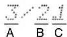
A: The number of front channels (front left, front right, and center).
B: The number of surround channels (surround left and surround right). If there's surround back channel information, this number will be 3.
C: LFE channel for subwoofer (1 means yes).
Listening to AM/FM stations
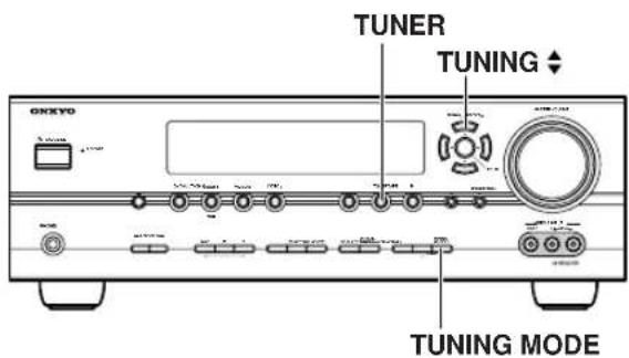
With the built-in tuner, you can enjoy AM and FM radio stations.
1
TUNER

Use the [TUNER] input selector button to select AM or FM.
In this example, FM has been selected.
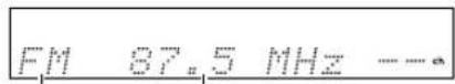
Band
Frequency
(Actual display depends on country.)
■ AM Frequency Step Setup (not North America)
You must specify the AM frequency step used in your area. Note that when this setting is changed, all radio presets are deleted.
1
Press the [SETUP] button, use the Up and Down [ʌ/ ] buttons to select "0. Hardware Setup," and then press [ENTER].
2
Use the Up and Down [A][ ] buttons to select "AM Freq," and then use the Left and Right [A][ ] buttons to select:
10 kHz: Select if 10 kHz steps are used in your area.
9 kHz: Select if 9 kHz steps are used in your area.
3
Press the [SETUP] button. Setup closes.
Tuning into AM/FM Radio Stations
■ Auto Tuning Mode
1
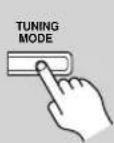
Press the [TUNING MODE] button so that the AUTO indicator appears on the display.
2
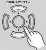
Press the TUNING Up or Down [▲]/[▼] button.
Searching stops when a station is found.
■ Manual Tuning Mode
1
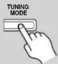
Press the [TUNING MODE] button so that the AUTO indicator disappears from the display.
2
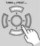
Press and hold the TUNING Up or Down [▲]/[▼] button.
The frequency stops changing when you release the button.
Press the buttons repeatedly to change the frequency one step at a time.
The American model changes FM frequency in 0.2 MHz steps, 10 kHz steps for AM. For other models it's 0.05 MHz steps for FM and 9 kHz (or 10 kHz) steps for AM.
When tuned into a station, the TUNED indicator appears. When tuned into a stereo FM station, the FM STEREO indicator also appears.
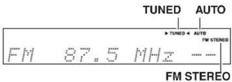
Tuning into Weak FM Stereo Stations
If the signal from a stereo FM station is weak, it may be impossible to get good reception. In this case, switch to Manual Tuning mode and listen to the station in mono.
Note:
- Y ou can also use the remote controller's Up and Down

] buttons to tune the radio.
■ Tuning into Stations by Frequency
You can tune into AM and FM stations directly by entering the appropriate frequency.
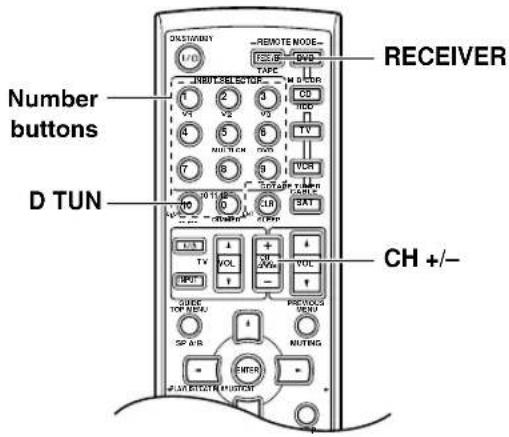
1

Press the [RECEIVER] button, followed by the [D TUN] button.
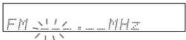
(Actual display depends on country.)
The [RECEIVER] button flashes.
2
Within 8 seconds, use the number buttons to enter the frequency of the radio station.
For example, to tune to 87.5 (FM), press 8, 7, 5.
Note: While the [RECEIVER] button is flashing, the input source cannot be changed by using the remote controller.
Presetting AM/FM Stations and XM Channels
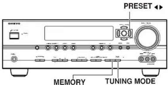
You can store a combination of up to 40 of your favorite AM/FM radio stations and XM channels as presets.
1
Tune into the AM/FM station or XM channel that you want to store as a preset.
See page 40 to select XM channels.
2

Press the [MEMORY] button.
The MEMORY indicator appears and the preset number flashes.
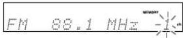
3
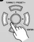
While the MEMORY indicator is displayed (about 8 seconds), use the PRESET [◀]/[▶] buttons to select a preset from 1 through 40.
4

Press the [MEMORY] button again to store the station or channel.
The station or channel is stored and the preset number stops flashing.
Repeat this procedure for all of your favorite AM/FM radio stations and XM channels.
■ Selecting Presets
1
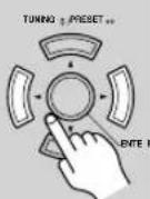
To select a preset, use the PRESET [◀]/[▶] buttons, or the remote controller's CH [+/-] button.
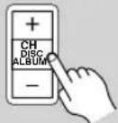
■ Deleting Presets
1
Select the preset that you want to delete.
See the previous section.
2
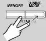
While holding down the [MEMORY] button, press the [TUNING MODE] button.
The preset is deleted and its number disappears from the display.
Listening to XM Satellite Radio® (North American Models Only)
Important XM Radio Information
To receive XM Radio on this receiver you need to purchase an optional XM Passport System and subscribe to XM's paid programming. Please note that XM is currently only licensed to provide service to the contiguous 48 United States (not available in Alaska and Hawaii) and portions of Canada. XM Radio service is not currently available in Mexico or any other region outside the continental U.S. and portions of Canada. For updates on service availability please visit XM's website at http://www.xmradio.com or http://www.xmradio.ca
Note:
Hardware and required basic monthly subscription sold separately. Premium Channels available at additional monthly cost. Installation costs and other fees and taxes, including a one-time activation fee may apply. Subscription fee is consumer only. All fees and programming subject to change.
About XM Radio:
There is a world beyond AM and FM. It is XM Satellite Radio. XM offers more than 160 digital channels of audio entertainment, including 100% commercial-free music channels, in the top markets in the U.S.
Channels with frequent explicit language are indicated with an XL. Channel blocking is available for XM radio receivers by calling 1-800-XMRADIO.
About XM Canada:
XM Canada offers the most commercial-free music – and engaging talk show programs. XM Canada creates original content that reflects our unique Canadian culture and broadcasts it throughout North America.
Canadian Satellite Radio Inc. offers its satellite radio service and operates under the XM Canada™ brand. XM Canada has an exclusive Canadian licence from XM Satellite Radio Inc.
For more information about XM Canada, visit www.xmradio.ca or call 1-877-GET-XMSR
A warning against reverse engineering:
It is prohibited to copy, decompile, disassemble, reverse engineer, or manipulate any technology incorporated in receivers compatible with the XM Satellite Radio system. Furthermore, the AMBE ^® voice compression software included in this product is protected by intellectual property rights including patent rights, copyrights, and trade secrets of Digital Voice Systems, Inc. The user of this or any other software contained in an XM Radio is explicitly prohibited from attempting to copy, decompile, reverse engineer, or disassemble the object code, or in any other way convert the object code into human-readable form. The software is licensed solely for use within this product.
Connecting the XM Passport System
The XM Passport System is sold separately. You can purchase the XM Passport System from the XM Web site at: http://www.xmradio.com (U.S.A.) http://www.xmradio.ca (Canada)
Connect the Passport System to the XM antenna jack on the rear panel.
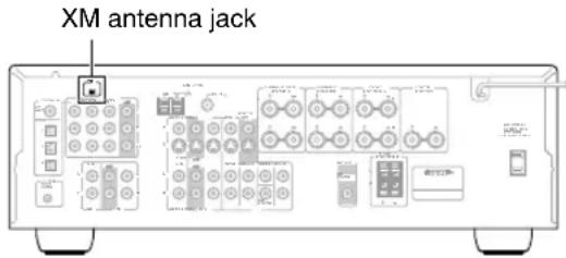
Put the XM Passport System by a southerly facing window, with nothing obstructing its path to the sky.
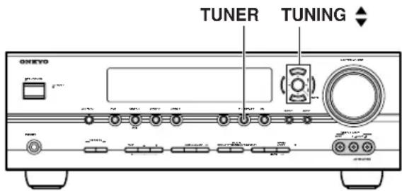
Selecting XM Satellite Radio
1
TUNER

Press the [TUNER] input selector button repeatedly to select XM.
If “CHECK ANTENNA” appears on the display, make sure the XM Passport System is connected properly.
Signing Up for XM Satellite Radio
Before you can use XM Satellite Radio, you must first sign up for an account. You'll need a major credit card and your XM Satellite Radio ID, which you can get from the AV receiver, as explained below, or from the Passport System package and itself.
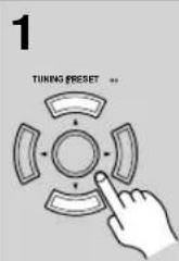
Use the TUNING Up and Down [√[ ] Buttons to select channel 0.
Your XM Satellite Radio ID number is displayed. Write it below.
ID
2
To sign up, go to: http://activate.xmradio.com
Or call: 1-800-967-2346
For XM Canada, go to:
http://xmradio.ca
Or call: 1-877-GET-XMSR
Notes:
- Channel 0 cannot be selected in Category Search mode. You must select Channel Search mode (see page 41).
• The following letters are not used in XM Satellite Radio IDs: I, O, S, F.
Selecting XM Radio Channels
There are three ways to select XM radio channels:
- Channel Search mode: select any channel.
- Category Search mode: select channels by category.
- Direct tuning: enter channel number.
Note:
You can't select Channel Search or Category Search mode, while the Tuning Arrow indicators are flashing, as tuning is in progress.
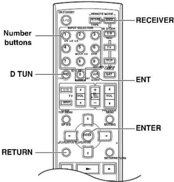
■ Channel Search Mode
Press the [RECEIVER] button, followed by the [ENTER] button to select "Channel Search" mode.
Channel Search
Use the Up and Down [▼] ▼ buttons to select a channel.
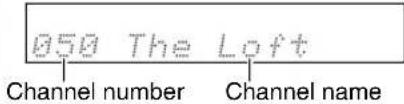
You can also use the Left and Right [◀▶buttons to select a category.
■ Category Search Mode

Press the [RECEIVER] button, followed by the [ENTER] button to select "Category Search" mode.
CategorySearch
Use the Left and Right [◀] ▶ buttons to select a category, and use the Up and Down [◀] ▼ buttons to select a channel in that category.
■ Direct Tuning
You can select an XM radio channel directly by entering its number.
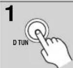
Press the [RECEIVER] button, followed by the [D TUN] button.
The [RECEIVER] button flashes.
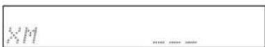
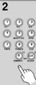
Within 8 seconds, use the number buttons to enter the channel number.
The channel is selected.
For example, to select channel #20, press 0, 2, 0, or 2, 0, [ENT].
Note: While the [RECEIVER] button is flashing, the input source cannot be changed by using the remote controller.
Selecting XM Channels from the Front Panel:
| 1 TUNING MODE | Press the [TUNING MODE] button to select "Channel Search" or "Category Search" mode. |
| 2 ENTER | Press the [ENTER] button repeatedly to select a category. |
| 3 TUNING 2 / PRESET++ | Use the TUNING Up and Down [X] Buttons to select a channel. In Channel Search mode, you can select any channel. In Category Search mode, you can only select channels from the currently selected category. |
Selecting the Previous Channel:
![1 AV receiver RETURN Remote controller RETURN To listen to the previously selected XM channel, press the [RETURN] button.](/content/2026/05/1062422/images/4ee3cf49407cf68578d356aed4aab7c499a2d6290015ca04e999bfbd80da53fb.jpg)
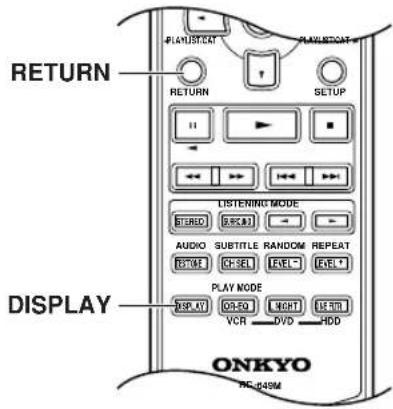
Displaying XM Radio Information
![1 AV receiver DISPLAY Remote controller DISPLAY Press the [DISPLAY] button repeatedly to cycle through the available information.](/content/2026/05/1062422/images/dcdc658a3e8a943e6f249c9caf9f20b00a85a25764d20b2145078bb3ac003a7e.jpg)
The following information can be displayed:
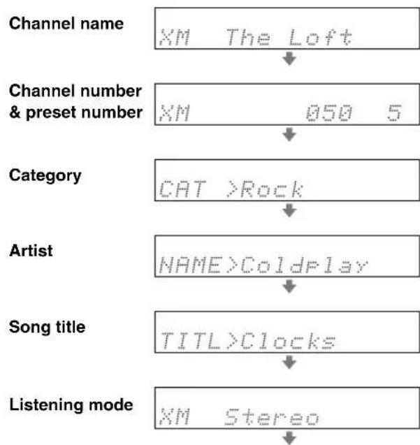
flowchart
graph TD
    A["Channel name"] --> B["XM The Loft"]
    B --> C["Channel number & preset number"]
    C --> D["XM 050 5"]
    D --> E["Category"]
    E --> F["CAT >Rock"]
    F --> G["Artist"]
    G --> H["NAME>Coldplay"]
    H --> I["Song title"]
    I --> J["TITL>Clocks"]
    J --> K["Listening mode"]
    K --> L["XM Stereo"]
Notes:
- If the category, artist, or song title is not available, “--” will be displayed instead.
- The listening mode is displayed only when speaker set A is on.
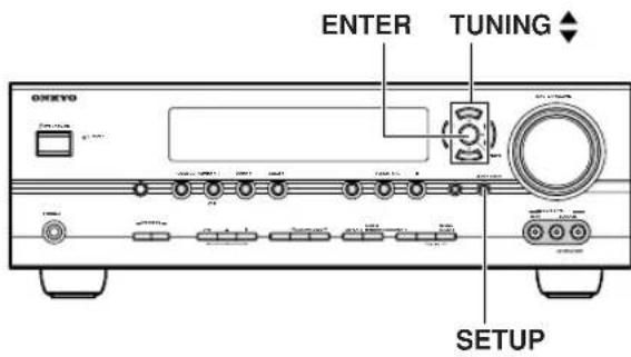
Positioning the XM Passport System
You can check the signal strength of the XM radio signal and adjust the position of the XM Passport System accordingly.
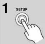
On the AV receiver, press the [SETUP] button.
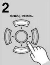
Use the Up and Down [▼]▼ buttons to select "5. ANT Aiming," and then press [ENTER].
- ANT Aiming
3 Adjust the position of the XM Passport System so that the SAT signal strength bar is as long as possible.
SAT: [********]......]
If you can't receive a satellite signal, press the Down [▼button to display the terrestrial (TER) signal strength meter and adjust your XM Passport System so that the bar is as long as possible.
Terrestrial signals are only available in certain areas.
TER: [ ]
So long as the signal strength is good, you can enjoy XM Radio by using either satellite or terrestrial reception.
XM Radio Messages
The following messages may appear while using XM radio.
CHECK ANTENNA
The XM Passport System is not connected properly. Check the connection.
UPDATING
The XM user encryption code is being updated. Please wait.
NO SIGNAL
The signal is too weak. Check the XM Passport System connection and reposition it for the best reception.
LOADING
The AV receiver is tuning or decoding audio or text data. Please wait.
OFF AIR
The XM channel you selected is not currently broadcasting. Select another channel.
Common Functions
This section explains functions that can be used with any input source.
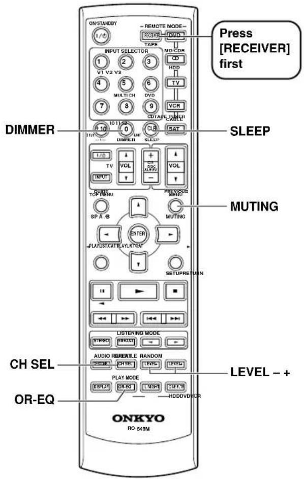
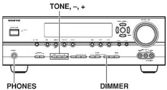
Setting the Display Brightness
You can adjust the brightness of the display.
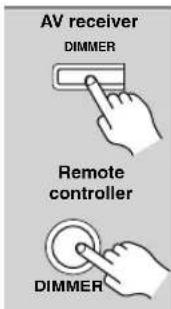
Press the [DIMMER] button repeatedly to select: dim, dim-mer, or normal brightness.
Adjusting the Bass and Treble
You can adjust the bass and treble for the front speakers, except when the Direct or Pure Audio (not North American models) listening mode is selected.
| 1 TONE | Press the AV receiver's [TONE] button repeatedly to select either Bass or Treble. |
| 2 | Use the TONE [-]/[+] buttons to adjust. |
■ Bass
You can boost or cut low-frequency sounds output by the front speakers from -10 dB to +10 dB in 2 dB steps.
Treble
You can boost or cut high-frequency sounds output by the front speakers from -10 dB to +10 dB in 2 dB steps.
Muting the AV Receiver
You can temporarily mute the output of the AV receiver.
![Press the remote controller's [MUTING] button. The output is muted and the MUTING indicator flashes on the display.](/content/2026/05/1062422/images/f7cf4de641aef1dc7d7f2cba419f258812d97713dcaccc56ae389e99a44e6420.jpg)
To unmute the AV receiver, press the remote controller's [MUTING] button again, or adjust the volume. The output is unmuted and the MUTING indicator goes off. Muting is cancelled when the AV receiver is set to Standby.
Using the OptiResponse Equalizer
When using the HT-R540 with the speakers included in this Package, by turning on the OptiResponse equalizer, you can enjoy a powerful sound with movies or music.
![Press the remote controller's [OR-EQ] button to turn the Opti- Response equalizer on or off.](/content/2026/05/1062422/images/22bfd2322a1a4a360f0e9e9c2bf4b81629fdea39f2d8c1c99e14135465f8273f.jpg)
Using the Sleep Timer
With the sleep timer, you can set the AV receiver so that it turns off automatically after a specified period.

Press the remote controller's [SLEEP] button repeatedly to select the required sleep time.
You can set the sleep time from 90 to 10 minutes in 10 minute steps.
The SLEEP indicator appears on the display when the sleep timer has been set, as shown. The specified sleep time appears on the display for about 5 seconds, then the previous display reappears.
SLEEP indicator
Sleep 90 min
To cancel the sleep timer, press the [SLEEP] button repeatedly until the SLEEP indicator disappears.
Tocheck the remaining sleep time, press the [SLEEP] button. Note that if you press the [SLEEP] button while the sleep time is being displayed, you'll shorten the sleep time by 10 minutes.
Using Headphones
For private listening, you can connect a pair of stereo headphones (1/4-inch phone plug) to the AV receiver's PHONES jack.
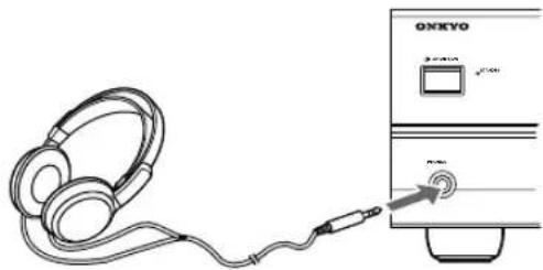
natural_image
Line drawing of a headset connected to an ONXTO CD-ROM via cable (no text or symbols on device)Notes:
- A 1ways turn down the volume before connecting your headphones.
- Speaker sets A and B are turned off while the headphones plug is inserted in the PHONES jack.
- When you connect a pair of headphones, the listening mode is set to Stereo, unless it was set to Pure Audio, Mono, Stereo, or Direct, in which case it stays the same.
- When the multichannel DVD input is selected, only the front left and front right channels can be heard in the headphones.
Adjusting Speaker Levels
You can adjust the volume of each speaker in speaker set A. These temporary adjustments are cancelled when the AV receiver is set to Standby.
1

Use the remote controller's [CH SEL] button to select each speaker, and use the [LEVEL-] and [LEVEL+] buttons to adjust the volume.
You can adjust the volume of each speaker from -12 dB to +12 dB (-15 dB to +12 dB for the subwoofer).
Left : 0dB
Notes:
- Y ou cannot use this function while the AV receiver is muted.
- Speakers that are set to No or None in the Speaker Configuration cannot be adjusted.
■ Speaker Set B
While speaker set B is on, you can adjust the volume of the left and right speakers, from -12 dB to +12 dB.
Left(B) : 0dB
• These settings are stored when the AV receiver is set to Standby.
- While speaker set B is on, you cannot adjust the levels of speaker set A's surround back speakers.
■ Headphones
While a pair of headphones is connected, you can adjust the volume of each headphone speaker, from -12 dB to +12 dB each.
HP Left : 0dB
• These settings are stored when the AV receiver is set to Standby.
Selecting Listening Modes
For a description of each listening mode, see “About the Listening Modes” on page 48.
- The Dolby Digital and DTS listening modes can only be selected if your DVD player is connected to the AV receiver with a digital audio connection (coaxial or optical).
- Listening mode availability depends on the format of the current input signal.
- While a pair of headphones is connected, you can select only the Pure Audio (not North American model), Mono, Direct, or Stereo listening mode.
- The listening modes cannot be selected while speaker set A is off.
Selecting on the AV Receiver
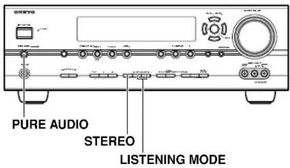
■ [PURE AUDIO] button (not North American model)
This button selects the Pure Audio listening mode. When this mode is selected, the AV receiver outputs no video signals and its display is turned off. Pressing this button again will select the previous listening mode.
■ [STEREO] button
This button selects the Stereo listening mode.
■ LISTENING MODE [◀] buttons
Pressing these buttons repeatedly cycles through all of the listening modes that can be used with the current input source.
Selecting with the Remote Controller
![ONKYO HT-S7400 - ■ LISTENING MODE [◀] buttons - 1](/content/2026/05/1062422/images/35e5002ce6524994e937ad26f10b288935d6c7342af1be8f5179378f14b79e94.jpg)
This button selects the Dolby Digital and DTS listening modes and the Neural Surround listening mode (North American model only).
■ LISTENING MODE [◀] buttons
Pressing these buttons repeatedly cycles through all of the listening modes that can be used with the current input source.
The following table shows which listening modes can be used with each input signal format.
| Source formatListening mode | Analog,PCM*1 | Dolby Digital | DTS/DTS 96/24*2 | Multichanalog | ||||||||
| 3/2.12/2.1 | 2/0 1/0, 1+1 Other | 3/2.12/2.1 | 2/0 | DTS-ES | ||||||||
| Discrete | Matrix | |||||||||||
| CD, TV,radio,cassette,etc. | DVD, DTV, etc. DVD, CD, etc. DVD | |||||||||||
| Pure Audio (Not NorthAmerican models)Direct | ✓ ✓ | ✓ | ✓ | ✓ | ✓ | ✓ | ✓ | ✓ | ||||
| StereoMono | ✓ ✓ | ✓ | ✓ | ✓ | ✓ | ✓ | ✓ | |||||
| Multich | ✓ | |||||||||||
| PLIIX Movie/Music/Game *3Neo:6 CinemaNeo:6 Music | ✓ | ✓ | ✓ | |||||||||
| Neural Surround (NorthAmerican models only) | ✓*4 | |||||||||||
| Dolby | Dolby D | ✓ | ✓ | |||||||||
| Dolby D + Neo:6Dolby D EXDolby D+PLIIX Music | ✓ | |||||||||||
| Dolby D+PLIIX Movie | ✓ | |||||||||||
| DTS | DTS, DTS 96/24 | ✓ | ✓*5 | |||||||||
| DTS-ES Discrete | ✓ | |||||||||||
| DTS-ES Matrix | ✓ | |||||||||||
| DTS+Neo:6DTS+Dolby EXDTS+PLIIX Music | ✓ | |||||||||||
| DTS+PLIIX Movie | ✓ | |||||||||||
| OnkyoOriginalDSP | Mono MovieOrchestraUnplugged Studio-MixTV LogicAll Ch StereoFull Mono | ✓ ✓ | ✓ | ✓ | ✓ | ✓ | ✓ | ✓ | ||||
*1. In the Pure Audio and Direct listening modes, 32 kHz, 44.1 kHz, and 48 kHz PCM is processed at 64 kHz, 88.2 kHz, and 96 kHz respectively. In listening modes other than Pure Audio, Direct, and Stereo, 64 kHz, 88.2 kHz, and 96 kHz PCM is processed at 32 kHz, 44.1 kHz, and 48 kHz respectively.
*2. In listening modes other than Pure Audio, Direct, Stereo, and DTS 96/24, DTS 96/24 sources are processed as normal DTS.
*3. If the Surr Back parameter is set to None, or speaker set B is on, normal Pro Logic II is used.
*4. Not available for 88.2 kHz and 96 kHz PCM input signals.
*5. If the Surr Back setting is set to None, or speaker set B is on, normal DTS is used.
*6. Available only when surround speakers are connected.
: Only available on 6.1/7.1-channel playback systems. Not available while speaker set B is on.
: Only available on 7.1-channel playback systems. Not available while speaker set B is on.
Tip: To check the format of the digital input signal, see “Displaying Source Information” on page 37.
About the Listening Modes
The AV receiver's listening modes can transform your listening room into a movie theater or concert hall, with high fidelity and stunning surround sound.
The illustration shows which speakers are active in each listening mode with 7.1 channel speaker system.
Front left Center Front right
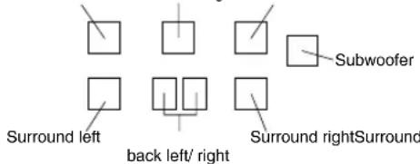
Pure Audio (not North American models)
In this mode, the display and video circuitry are turned off, minimizing possible noise sources for the ultimate in high-fidelity reproduction. (As the video circuitry is turned off, no video signals are output in this mode.)
Direct
In this mode, audio from the input source is output directly with minimal processing, providing high-fidelity reproduction. All of the source's audio channels are output as they are.
Stereo

Sound is output by the front left and right speakers and subwoofer.
Mono

Use this mode when watching an old movie with a mono soundtrack, or use it with the foreign language soundtracks recorded in the left and right channels of some movies. It can also be used with DVDs or other sources containing multiplexed audio, such as karaoke DVDs.
Dolby Pro Logic IIx

Dolby Pro Logic II

Dolby Pro Logic IIx expands any 2-channel source for 7.1-channel playback. It provides a very natural and seamless surround-sound experience that fully envelops the listener. As well as music and movies, video games can also benefit from the dramatic spatial effects and vivid imaging. If you're not using any surround back speakers, Dolby Pro Logic II will be used instead of Dolby Pro Logic IIx.
- PLIIx Movie
Use this mode with any stereo or Dolby Surround (Pro Logic) movie (e.g., TV, DVD, VHS).
- PLIIx Music
Use this mode with any stereo or Dolby Surround (Pro Logic) music source (e.g., CD, radio, cassette, TV, VHS, DVD).
- PLIIx Game
Use this mode with video games, especially those that bear the Dolby Pro Logic II logo.
Dolby Digital

Use this mode with DVDs that bear the

Dolby Digital logo, and Dolby Digital TV broadcasts. This is the most common digital surround-sound format, and it'll put you right in the middle of the action, just like being in a movie theater or concert hall.
Dolby Digital EX DTS+Dolby EX

These modes expand 5.1-channel Dolby Digital and DTS sources for 6.1/7.1-channel playback. They're especially suited to Dolby Digital EX soundtracks that include a matrix-encoded surround back channel. The additional channel adds an extra dimension and provides an enveloping surround sound experience, perfect for rotating and fly-by sound effects. Use them with DVDs that bear the Dolby Digital or DTS logo.


Dolby Digital+PLIIx Music DTS+PLIIx Music

These modes use the Pro Logic IIx Music mode to expand 5.1-channel Dolby Digital and DTS sources for 6.1/7.1-channel playback. Use them with Dolby Digital or


DTS 5.1 music sources (e.g., DVD and Dolby Digital TV broadcasts).
Dolby Digital+PLIIx Movie DTS+PLIIx Movie

These modes use the Pro Logic IIx Movie mode to expand 5.1-channel Dolby Digital and DTS sources for 7.1-channel playback. Use them with Dolby Digital and DTS 5.1 movies (e.g., DVD and select digital TV broadcasts).


DTS
The DTS digital surround-sound format supports up to 5.1 discrete channels and uses less compression for high-fidelity reproduction. Use it with DVDs and CDs that bear the DTS logo.

DTS 96/24

This mode is for use with DTS 96/24 sources. This is high-resolution DTS with a 96 kHz sampling rate and 24-bit resolution, providing superior fidelity. Use it with DVDs that bear the DTS 96/24 logo.

DTS-ES Discrete

This mode is for use with DTS-ES Discrete soundtracks, which use a discrete surround back channel for true 6.1/7.1-channel playback. The seven totally separate audio channels provide better spatial imaging and 360-degree sound localization, perfect for sounds that pan across the surround channels. Use it with DVDs that bear the DTS-ES logo, especially those with a DTS-ES Discrete soundtrack.
DTS-ES Matrix

This mode is for use with DTS-ES Matrix soundtracks, which use a matrix-encoded back-channel for 6.1/7.1-channel playback DVDs that bear the DTS-ES logo, especially a DTS-ES Matrix soundtrack.

DTS Neo:6

This mode expands any 2-channel source for 6.1-channel playback. It uses six full-bandwidth channels of matrix decoding for matrix-encoded material, providing a very natural and seamless surround sound experience that fully envelops the listener.
- Neo:6 Cinema
Use this mode with any stereo movie (e.g., TV, DVD, VHS).
- Neo:6 Music
Use this mode with any stereo music source (e.g., CD, radio, cassette, TV, VHS, DVD).
This mode uses Neo:6 to expand 5.1-channel Dolby Digital and DTS sources for 6.1/7.1-channel playback. Use it with DVDs that bear the Dolby Digital or DTS logo and feature a 5.1-channel soundtrack.


Neural Surround

(North American models only)
Neural Surround represents the latest advancement in surround technology developed for music and is adopted by XM Satellite Radio for digital radio broadcast of surround recordings and live events in surround sound. Neural Surround employs psychoacoustic frequency-domain processing, which allows delivery of a more detailed sound stage, with superior channel separation and localization of audio elements. System playback is scalable from 5.1 to 7.1 multichannel surround playback.
Onkyo Original DSP Modes
Mono Movie

This mode is suitable for old movies and other mono sources. The center speaker outputs the sound as it is, while reverb is applied to the sound output by the other speakers, giving presence to even mono material.
Orchestra

Suitable for classical or operatic music, this mode emphasizes the surround channels in order to widen the stereo image, and simulates the natural reverberation of a large hall.
Unplugged

Suitable for acoustic instruments, vocals, and jazz, this mode emphasizes the front stereo image, giving the impression of being right in front of the stage.
Studio-Mix

Suitable for rock or pop music, listening to music in this mode creates a lively sound field with a powerful acoustic image, like being at a club or rock concert.
TV Logic

This mode adds realistic acoustics to TV shows produced in a TV studio, surround effects to the entire sound, and clarity to voices.
All Ch Stereo

Ideal for background music, this mode fills the entire listening area with stereo sound from the front, surround, and surround back speakers.
Full Mono

In this mode, all speakers output the same sound in mono, so the sound you hear is the same regardless of where you are within the listening room.
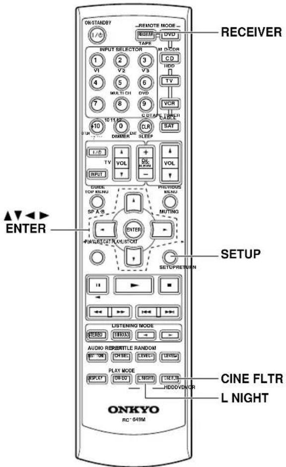
Using the Late Night Function (Dolby Digital only)
With the Late Night function, you can reduce the dynamic range of Dolby Digital material so that you can still hear quiet parts even when listening at low volume levels—ideal for watching movies late at night when you don't want to disturb anyone.
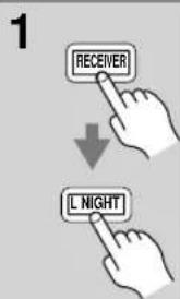
Press the [RECEIVER] REMOTE MODE button, and then press the [L NIGHT] button repeatedly to select:
Off: Late Night function off.
Low: Small reduction in dynamic range.
High: Big reduction in dynamic range.
Notes:
- The effect of the Late Night function depends on the Dolby Digital material that you are playing, and with some material there will be little or no effect.
- The Late Night function is set to Off when the AV receiver is set to Standby.
Using the CinemaFILTER
With the CinemaFILTER, you can soften overly bright movie soundtracks, which are typically mixed for reproduction in a movie theater.
CinemaFILTER can be used with the following listening modes: Dolby Digital, Dolby Digital EX, PLII/IIx Movie, DTS, DTS-ES, DTS Neo:6 Cinema, DTS 96/24, Dolby/DTS+PLIIx Movie, Dolby/DTS+Neo:6, and DTS+Dolby EX.
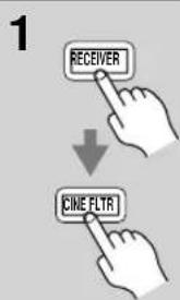
Press the [RECEIVER] REMOTE MODE button, and then press the [CINE FLTR] button repeatedly to select:
On: CinemaFILTER on. Off: CinemaFILTER off.
Using the Audio Adjust Settings
The Audio Adjust settings only affect speaker set A.
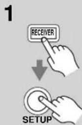
Press the [RECEIVER] button followed by the [SETUP] button.
![ONKYO HT-S7400 - Press the [RECEIVER] button followed by the [SETUP] button. - 1](/content/2026/05/1062422/images/ec81daa81c6948bf6b296597f0ff2c056f22f828325e33cd74805c024c72ef73.jpg)
flowchart
graph TD
    A["ENTER"] --> B["↓"]
    B --> C["ENTER"]
Use the Up and Down [][ ]▼ buttons to select "4. Audio Adjust," and then press [ENTER].
- Audio Adjust
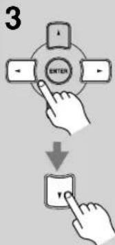
Use the Left and Right [◀] ▶ buttons to change the setting.
Press the Down [▼button to select the next setting. Repeat this step for the other settings.
4
![ONKYO HT-S7400 - Use the Left and Right [◀] ▶ buttons to change the setting. - 1](/content/2026/05/1062422/images/ef0b03c534131b7bf14999d571a900ea7551835a78438b35ee2585043bdaecc2.jpg)
Press the [SETUP] button.
Setup closes.
The Audio Adjust settings are explained below.
Input Channel Settings
■ Multiplex
This setting determines which channel is output from a stereo multiplex source. Use it to select audio channels or languages with multiplex sources, multilingual TV broadcasts, and so on.
Main: The main channel is output (default).
Sub: The sub channel is output.
M/S: Both the main and sub channels are output.
■ Mono (2ch)
This setting determines which channel is output when the Mono listening mode is used with a stereo source.
L+R: Both the left and right channels are output (default).
L: Only the left channel is output.
R: Only the right channel is output.
PLII and PLIIx Music Mode Settings
These settings apply to only 2-channel (stereo) sources.
Panorama
With this setting, you can broaden the width of the front stereo image when using the Pro Logic II Music or Pro Logic IIx Music listening mode.
On: Panorama function on.
Off: Panorama function off (default).
■ Dimension
With this setting, you can move the sound field forward or backward when using the Pro Logic II Music or Pro Logic IIx Music listening mode. The default value is 3. It can be adjusted from 0 to 6. Higher settings move the sound field forward. Lower settings move it backward. If the stereo image feels too wide, or there's too much surround sound, move the sound field forward to improve the balance. Conversely, if the stereo image feels like it's in mono, or there's not enough surround sound, move it backward.
■ Center Width
With this setting, you can adjust the width of the sound from the center speaker when using the Pro Logic II Music or Pro Logic IIx Music listening mode. Normally, the center channel sound is output by only the center speaker. (If you're not using a center speaker, the center channel sound will be distributed to the front left and right speakers to create a phantom center). This setting
adjusts the front left, right, and center mix, allowing you to adjust the weight of the center channel sound. It can be adjusted from 0 to 7 (default value is 3).
DTS Neo:6 Music Mode Setting
■ Center Image
The DTS Neo:6 Music listening mode creates 6-channel surround sound from 2-channel (stereo) sources. With this setting, you can specify by how much the front left and right channel output is attenuated in order to create the center channel. It can be adjusted from 0 to 5 (default value is 2). This setting has no effect if no center speaker is connected.
When set to 0, the front left and right channel output is attenuated by half (-6 dB), giving the impression that the sound is located centrally. This setting works well when the listening position is considerably off center. When set to 5, the front left and right channels are not attenuated, maintaining the original stereo balance.
Dolby Digital EX Input Signal Setting
■ Dolby EX
This setting determines how Dolby Digital EX signals are handled. This setting is unavailable if no surround back speakers are connected or speaker set B is on.
Auto: If the source signal contains a Dolby Digital EX flag, the Dolby Digital EX listening mode is used (default).
Manual: You can select Pro Logic IIx Movie, Pro Logic IIx Music, Dolby Digital, or Dolby Digital EX.
Multichannel Subwoofer Setting
■ SW Sens
On some DVD players, the signal from the multichannel subwoofer output is 15 dB higher than normal. You can change the subwoofer sensitivity to match your DVD player. Note that this setting only affects signals connected to the SUBWOOFER input jack of the multichannel DVD input.
You can select 0 dB (default), +5 dB, +10 dB, or +15 dB. If you find that your subwoofer is too loud, try the +10 dB or +15 dB setting.
Advanced Speaker Settings
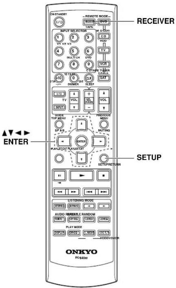
Speaker Distance
The speaker distance setting cannot be changed while a pair of headphones is connected, speaker set B is on, or the multichannel input is being used.
To get the best from surround sound, it's important that the sound from each speaker reaches the listener at the same time. To achieve this, you need to specify the distance from each speaker to the listening position.
1
Measure and make a note of the distance from each speaker to the listening position.
2
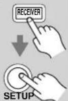
Press the [RECEIVER] button followed by the [SETUP] button on the remote controller.
3
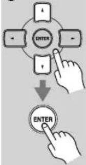
flowchart
graph TD
    A["Enter"] --> B["Down Arrow"]
    B --> C["ENTER"]
Use the Up and Down [][]▼ buttons to select "2. SP Distance," and then press the [ENTER] button.
2.5P Distance
4
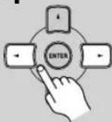
While "Unit" is displayed, use the Left and Right [ ] buttons to select "feet" or "meters".
feet: Distances in feet. Can be set from 1 to 30 feet in 1-foot steps.
meters: Distances in meters. Can be set from 0.3 to 9 meters in 0.3-meter steps.
5
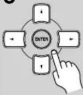
Use the Down [▼button to select "Front," and use the Left and Right [★] ▶buttons to specify the distance for the "front speakers," then press the Down [▼] button to select the next speaker.
6
Repeat step 5 for all speakers. Note:
Speakers that you set to No or None in the Speaker Configuration (page 54) cannot be selected.
7
Press the [SETUP] button. Setup closes.
Notes:
- The Center and Subwoofer distances can be set up to 5 ft. (1.5 m) more or less than the Front distance. For example, if the Front distance is set to 20 ft. (6 m), the Center and Subwoofer distances can be set between 15 and 25 ft. (4.5 and 7.5 m).
- The Surround and Surround Back distances can be set up to 5 ft. (1.5 m) more or 15 ft. (4.5 m) less than the Front distance. For example, if the Front distance is set to 20 ft. (6 m), the SurrRight, Surr Left, Surr Back R, and Surr Back L distances can be set between 5 and 25 ft. (1.5 and 7.5 m).
Speaker Levels
With this function, you can adjust the volume of each speaker so that all speakers can be heard equally at the listening position.
The speaker levels cannot be adjusted while a pair of headphones is connected, speaker set B is on, or the AV receiver is muted.
1
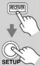
Press the [RECEIVER] button followed by the [SETUP] button on the remote controller.
2
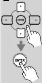
flowchart
graph TD
    A["ENTER"] --> B["↓"]
    B --> C["ENTER"]
Use the Up and Down [][ ]▼ buttons to select "3. Level Cal," and then press the [ENTER] button.
A pink noise test tone is output by the front left speaker.
S. Level Cal
3
Turn up the volume so that you can hear the test tone sufficiently.
While each speaker outputs the test tone, its name appears on the display, as shown.
Left
: 0dB
4
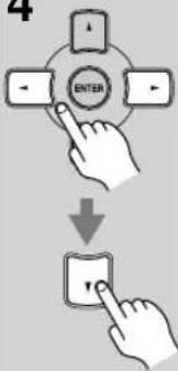
flowchart
graph TD
    A["Enter"] --> B["Arrow Left"]
    A --> C["Arrow Right"]
    A --> D["Arrow Down"]
    A --> E["Arrow Up"]
    F["↓"] --> G["Enter Button"]
Use the Left and Right [◀]▶ buttons to adjust the speaker level, and use the Down [▼button to select the next speaker.
The level can be adjusted from -12 to +12 dB in 1 dB steps (-15 to +12 dB for the subwoofer).
5
Repeat step 4 so that the level of the test tone from each speaker is the same.
Speakers that you set to No or None in the Speaker Configuration (page 54) do not output the test tone.
6

Press the [SETUP] button.
Setup closes.
Don't forget to turn down the volume if you turned it up while setting the levels.
Note:
- A quicker way to adjust the speaker levels is to press the remote controller's [TEST TONE] button to output the test tone, use the [LEVEL-] and [LEVEL+] buttons to adjust the levels, and use the [CH SEL] button to select the speakers.
Speaker Configuration, Crossover Frequency, and Double Bass settings only need to be changed if you're not using the speakers in this package.
These settings cannot be changed while headphones are connected, speaker set B is on, or the multichannel DVD input is being used.
Speaker Configuration
This section explains how to specify which speakers are connected and their sizes.
For speakers with a cone diameter larger than 6-1/2 inches (16 cm), specify Large (full band). For those with a smaller diameter, specify Small (default crossover 100 Hz).
The crossover frequency can be changed on page 55.
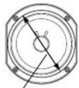
Cone diameter
1

Press the [RECEIVER] button followed by the [SETUP] button.
2
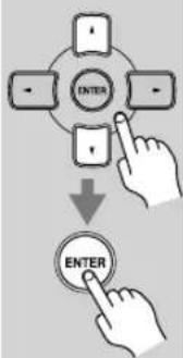
flowchart
graph TD
    A["Enter"] --> B["Arrow"]
    B --> C["ENTER"]
Use the Up and Down [][ ]▼ buttons to select "1. SP Config," and then press the [ENTER] button.
- SP Config
3
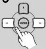
While the Subwoofer setting is selected, use the Left and Right [34] buttons to select Yes or No.
Yes: Select if a subwoofer is connected.
No: Select if no subwoofer is connected.
4
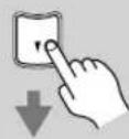
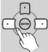
Use the Down [button to select "Front," and then use the Left and Right [] buttons to select Small or Large.
Small: Select if the front speakers are small.
Large: Select if the front speakers are large.
Note:
- If the Subwoofer setting in step 3 is set to No, this setting is fixed at Large and does not appear.
5
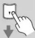
Use the Down [button to select "Center," and then use the Left and Right [ ] buttons to select Small, Large, or None.
Small: Select if the center speaker is small.
Large: Select if the center speaker is large.
None: Select if no center speaker is connected.
Note:
- If the Front setting in step 4 is set to Small, the Large option cannot be selected.
6
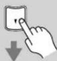
Use the Down [button to select "Surround," and then use the Left and Right [H] buttons to select Small, Large, or None.
Small: Select if the surround speakers are small.
Large: Select if the surround speakers are large.
None: Select if no surround speakers are connected.
Note:
- If the Front setting in step 4 is set to Small, the Large option cannot be selected.
7

Use the Down [button to select "Surr Back," and use the Left and Right [] buttons to select Small, Large, or None.
Small: Select if the surround back speakers are small.
Large: Select if the surround back speakers are large.
None: Select if no surround back speakers are connected.
Notes:
- If the Surround setting in step 6 is set to None, this setting does not appear.
- If the Surround setting in step 6 is set to Small, the Large option cannot be selected.
8
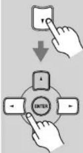
Use the Down [button to select "Surr Back Ch," and use the Left and Right [ ] buttons to select 2ch or 1ch.
2ch: Select if two (left and right) surround back speakers are connected.
1ch: Select if one surround back speaker is connected.
Note:
- If the Surround and Surr Back settings in steps 6 and 7 are set to None, this setting does not appear.
Continue with step 9 of the “Crossover Frequency” setting.
Crossover Frequency
This setting only applies to the speakers that you specified as Small in the "Speaker Configuration" on page 54. To get the best bass performance from your speaker system, you need to set the crossover frequency according to the size and frequency response of your speakers
9
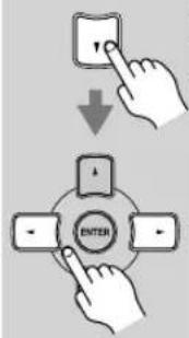
Use the Down [button to select "Crossover," and then use the Left and Right [button] to select a crossover frequency.
Use the diameter of the smallest speaker in your system when choosing the crossover frequency.
| Speaker cone diameter | Crossover frequency |
| Over 8 in. (20 cm) | 40/50/60Hz* |
| 6-1/2 to 8 in. (16–20 cm) | 80Hz |
| 5-1/4 to 6-1/2 in. (13–16 cm) | 100Hz (default) |
| 3-1/2 to 5-1/4 in. (9–13 cm) | 120Hz |
| Under 3-1/2 in. (9 cm) | 150/200Hz* |
*Choose the setting suitable for the speaker.
Continue with step 10 of the "Double Bass" setting below.
Notes:
- F or a more accurate setting, look up the frequency response in the manuals supplied with your speakers and set accordingly.
- Choose a higher crossover frequency if you want more sound from your subwoofer.
Double Bass
With the Double Bass function, you can boost bass output by feeding bass sounds from the front left and right channels to the subwoofer. This function can be set only if the Subwoofer setting (step 3) is set to Yes, and the Front setting (step 4) is set to Large in the Speaker Configuration on page 54.
10
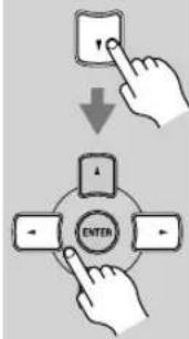
Use the Down [ ] button to select "Double Bass," and then use the Left and Right [ ] ▶ buttons to select:
On: Double Bass function on. Bass from the front left and right channels is also fed to the subwoofer (default).
Off: Double Bass function off.
11

Press the [SETUP] button.
Setup closes.
Digital Input Signal Formats
The following table shows the display indicator for each digital signal format.
| Format Display | |
| Dolby Digital | |
| DTS | |
| PCM | PCM |
Normally, the AV receiver detects the signal format automatically. However, if you experience either of the following issues when playing PCM or DTS material, you can specify the signal format as either PCM or DTS:
- If the beginnings of tracks from a PCM source are cut off, try the PCM setting.
- If noise is produced when fast forwarding or reversing a DTS CD, try the DTS setting.
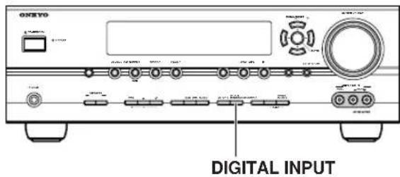
1 Press and hold the AV receiver's [DIGITAL INPUT] button for about 3 seconds.
2 While "Auto" is displayed (about 3 seconds), press the [DIGITAL INPUT] button repeatedly to select: PCM, DTS, or Auto.
PCM: Only PCM format input signals will be heard. If the input signal is not PCM, the PCM indicator will flash and there will be no sound.
DTS: Only DTS format input signals will be heard. If the input signal is not DTS, the DTS indicator will flash and there will be no sound.
Auto (default): The format is detected automatically. If no digital input signal is present, the corresponding analog input is used instead.
Correcting Sound and Picture Sync
When using progressive scanning on your DVD player, you may find that the picture and sound are out of sync. With this setting, you can correct this by delaying the audio signals. You can set it from 0 to 100 milliseconds (ms) in 20 millisecond steps.
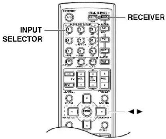
| 1 | Press the [RECEIVER] REMOTE MODE button. |
| 2 | Press and hold, for more than 4 seconds, the input selector button for the input source that you want to correct.This can be the [DVD], [VIDEO 1], [VIDEO 2], or [VIDEO 3] input source. |
| 3 | Use the Left and Right [◀]/[▶] buttons to adjust the delay from 0 to 100 milliseconds in 20 millisecond steps.A/V Sync : 20ms |
Note:
- This setting is not available when the Pure Audio listening mode is used, or the Direct listening mode is used with an analog input signal.
This section explains how to record the selected input source to a component with recording capability, and how to record audio and video from different sources.
Recording the Input Source
You can only record to a component that's connected to the TAPE OUT or VIDEO 1 OUT jacks.
See pages 22–33 for information on connecting your AV components.
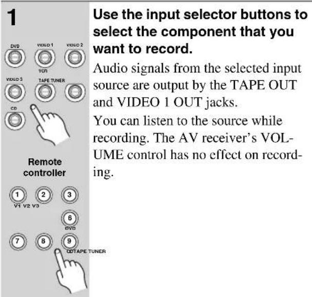
| 2 | On your recorder, start record- ing. |
| 3 | Start playback on the source component. |
Notes:
- Y ou cannot record from a component that's connected to a digital input. Only analog inputs can be recorded.
- The surround sound effects provided by the listening modes cannot be recorded.
- You cannot record from a component that's connected to the multichannel DVD input.
- If you select another input source while recording, that input source will be recorded instead.
- While the Pure Audio listening mode is selected, the VIDEO I OUT V and S jacks don't output video signals, so select another mode when recording.
Recording Audio and Video from Separate Sources
You can overdub audio onto your video recordings by simultaneously recording audio and video from two separate sources. This is possible because only the audio source is switched when an audio-only input source, such as TAPE, TUNER, or CD, is selected, the video source remains the same.
In the following example, audio from the CD player connected to the CD IN jacks, and video from the camcorder connected to the VIDEO 3 INPUT VIDEO jack are recorded by the VCR connected to the VIDEO 1 OUT jacks.
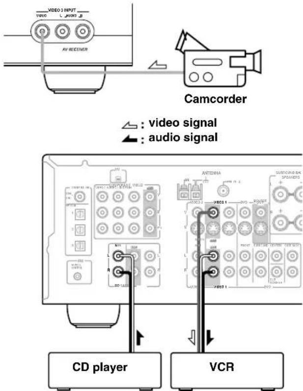
- Prepare the camcorder and CD player for playback.
- Prepare the VCR for recording.
- Press the [VIDEO 3] input selector button.
- Press the [CD] input selector button.
This selects the CD player as the audio source, but leaves the camcorder as the video source.
- Start recording on the VCR, then start playback on the camcorder and CD player.
Video from the camcorder and audio from the CD player are recorded by the VCR.
Controlling Other Components
You can use the AV receiver's remote controller (RC-649M) to control your other AV components, including those made by other manufacturers. This section explains how to enter the necessary remote control code for the component that you want to control (e.g., DVD player, TV, or VCR).
Entering Remote Control Codes
To control another component, you must first enter the appropriate remote control code to a REMOTE MODE button. You'll need to enter a code for each component that you want to control.
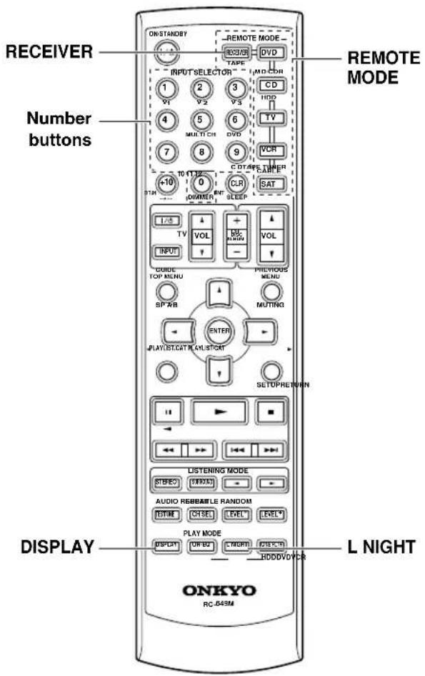
1
Look up the appropriate remote control code in the separate Remote Control Codes list.
The codes are organized by category (e.g., DVD player, TV, etc.).
2
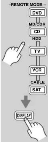
flowchart
graph TD
    A["REMOATE MODE"] --> B["DVD"]
    B --> C["MD/CDR"]
    C --> D["CD"]
    D --> E["HDD"]
    E --> F["TV"]
    F --> G["VCR"]
    G --> H["CABLE"]
    H --> I["SAT"]
    I --> J["DISPLAY"]
While holding down the REMOTE MODE button that you want to set, press the [DISPLAY] button for 3 seconds.
The REMOTE MODE button lights up.
3
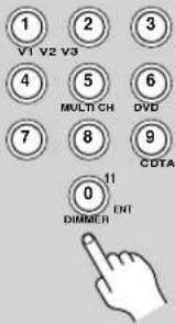
Within 30 seconds, use the number buttons to enter the 4-digit remote control code.
The REMOTE MODE button flashes twice.
4
Press the REMOTE MODE button again to select the remote controller mode, point the remote controller at the component, and check the operation.
If the remote controller doesn't work as expected, and several remote codes are listed, try each one in turn and use the one that works best.
Notes:
- A remote control code cannot be entered for the [RECEIVER] REMOTE MODE button.
- The remote control codes provided are correct at the time of printing, but are subject to change.
Remote Control Codes for Onkyo Components Connected via RI
Onkyo components that are connected via rare controlled by pointing the remote controller at the AV receiver, not the component. This allows you to control components that are out of view, in a rack, for example.
1 Make sure the Onkyo component is connected with an Rable and an analog audio cable (RCA).
See page 33 for details.
2 Enter the appropriate remote control code for the [DVD] or [CD] REMOTE MODE button.
[DVD] REMOTE MODE button
1612: Onkyo DVD player with RI
[CD/MD/CDR/HDD] REMOTE MODE button
1327: Onkyo CD player with RI
1808: Onkyo MD recorder with RI
1322: Onkyo CD recorder with RI
1993: HDD-compatible component with RI
See the previous page for how to enter remote control codes.
3 Press the [DVD] or [CD] REMOTE MODE button, point the remote controller at the AV receiver, and operate the component.
If you want to control an Onkyo component by pointing the remote controller directly at it, or you want to control an Onkyo component that's not connected via Rise the following remote control codes:
[DVD] REMOTE MODE button
0627: Onkyo DVD player without (default)
[CD/MD/CDR/HDD] REMOTE MODE button
1817: Onkyo CD player without (default)
0868: Onkyo MD recorder without RI
1323: Onkyo CD recorder without RI
1990: HDD-compatible component without RI
Note:
If you connect an f#pable Onkyo MD recorder, CD recorder, or HDD-compatible component to the TAPE IN/OUT or VIDEO 2 jacks, for remote operation to work properly, you must set the Input Display to MD, CDR, or HDD (see page 35).
Resetting REMOTE MODE Buttons
You can reset a REMOTE MODE button to its default remote control code.
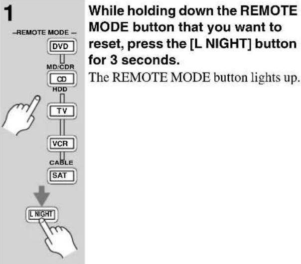
flowchart
graph TD
    A["REMOATE MODE"] --> B["DVD"]
    B --> C["MD/CDR"]
    C --> D["CD"]
    D --> E["HDD"]
    E --> F["TV"]
    F --> G["VCR"]
    G --> H["CABLE"]
    H --> I["SAT"]
    I --> J["L NIGHT"]
2 Press the REMOTE MODE button again.
The REMOTE MODE button flashes twice, indicating that it's been reset.
The [DVD] and [CD] REMOTE MODE buttons are preprogrammed with remote control codes for controlling Onkyo DVD players and CD players respectively. When these buttons are reset, the preprogrammed code is restored.
Resetting the Remote Controller
You can reset the remote controller to its default settings.
![1 RECEIVER ↓ L NIGHT While holding down the [RECEIVER] REMOTE MODE button, press the [L NIGHT] button for 3 seconds. The [RECEIVER] button lights up.](/content/2026/05/1062422/images/04e340e07933baeab380ca2683e2ea8b63030e19b36f677c3659462d1d05bfe9.jpg)
2 Press the [RECEIVER] REMOTE MODE button again.
The [RECEIVER] button flashes twice, indicating that it's been reset.
To control another component, point the remote controller at it and use the buttons explained below. (You must select the appropriate remote control mode first.) With some AV components, certain buttons may not work as expected, and some may not work at all.
■ Controlling a TV
![① ② ③ ④ ⑤ ⑥ ⑦ Press [TV] first ① ② ③ ④ ⑤ ⑥ ⑦](/content/2026/05/1062422/images/4e64ead11c978f55bf4e3fb622356dbcd07ab8f5e4fd52de28caf389db273508.jpg)
① [ON/STANDBY], TV [∅/1]
Sets the TV to On or Standby.
② Number buttons
Enter numbers.
③ TV VOL [W] ^* ▼
Adjusts the TV's volume.
④ [CH +/-] Selects channels on the TV.
⑤ [PREVIOUS] Selects the previous channel.
⑥ [TV INPUT]* Selects the TV's VCR input.
⑦ [■] ▶ [ ■ ] , [◀] [ ], [▶] Operates the VCR.
* Buttons marked with an asterisk (*) are exclusively for controlling a TV and can be used at anytime regardless of the current remote controller mode.
■ Controlling a VCR
![CNTV/TV 1/CD 2 3 4 5 6 7 8 9 10 11 12 13 14 15 16 17 18 19 20 21 22 23 24 25 26 27 28 29 30 31 32 33 34 35 36 37 38 39 40 41 42 43 44 45 46 47 48 49 50 51 52 53 54 55 56 57 58 59 60 61 62 63 64 65 66 67 68 69 70 71 72 73 74 75 76 77 78 79 80 81 82 83 84 85 86 87 88 89 90 91 92 93 94 95 96 97 98 99 100 Press [VCR] first](/content/2026/05/1062422/images/3ef6420ffb65a9794a31c580c494e080ee44a3c7bbe6e0fba5161b87ad85c5c9.jpg)
① [ON/STANDBY] Sets the VCR to On or Standby.
② Number buttons Select channels.
③ [CLR] Cancels functions.
④ [CH +/-] Selects channels on the VCR.
⑤ [■,▶[■,[] Pause, Play, Stop.
⑥ [◀◀] ▶▶ [ ] Rewind and Fast forward.
■ Controlling a Satellite or Cable Receiver
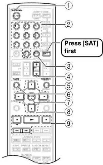
① [ON/STANDBY]
Sets the satellite/cable receiver to On or Standby.
② Number buttons
Enter numbers.
③ [CLR] Cancels functions.
④ [CH +/-] Selects satellite/cable channels.
⑤ [PREVIOUS] Selects the previous channel.
⑥ [GUIDE] Displays the program guide.
⑦ [ENTER] Confirms the selection.
⑧ [▼]/[▼/[]◀ ▶ Selects menu items.
⑨ [■] ,▶[ ■ ] , [◀] [ ], [◀] Operates the VCR.
If you have any trouble using the 7.1ch Home Theater System, look for a solution in this section.
If you can't resolve the issue yourself, try resetting the AV receiver before contacting your Onkyo dealer.
To reset the AV receiver to its factory defaults, turn it on and, while holding down the [VIDEO 1] button, press the [STANDBY/ON] button. "Clear" will appear on the display and the AV receiver will enter Standby mode.
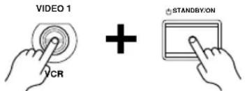
Note that resetting the AV receiver will delete your radio presets and custom settings.
Power
Can't turn on the AV receiver
- Make sure that the power cord is plugged into the wall outlet properly.
- Unplug the power cord from the wall outlet, wait 5 seconds or more, then plug it in again.
The AV receiver turns off as soon as it's turned on
- The amp protection circuit has been activated. Remove the power cord from the wall outlet immediately. Disconnect all speaker cables and input sources, and leave the AV receiver with its power cord disconnected for 1 hour. After that, reconnect the power cord and set the volume to maximum. If the AV receiver stays on, set the volume to minimum, disconnect the power cord, and reconnect your speakers and input sources. If the AV receiver turns off when you set the volume to maximum, disconnect the power cord, and contact your Onkyo dealer.
Audio
There's no sound or it's very quiet
- Make sure that the digital input source is selected properly (page 35). Press the [DIGITAL INPUT] button repeatedly.
- Make sure the speaker set A or B is on (page 5).
- Make sure that all audio connecting plugs are pushed in all the way (page 22).
- Make sure that the polarity of the speaker cables is correct, and that the bare wire is in contact with metal part of each speaker terminal (page 19)
- Make sure that the speaker cables are not shorting.
-
Check the volume. It can be set to MIN, 1 through 79, or MAX (page 36). The AV receiver is designed for home theater enjoyment and has a wide volume range for precise adjustment.
-
If the MUTING indicator is shown on the display, press the remote controller's [MUTING] button to unmute the AV receiver (page 44).
- While a pair of headphones is connected to the PHONES jack, no sound is output by the speakers (page 45).
- Check the digital audio output settings on the connected device. On some games consoles, such as those that can play DVDs, the default setting is off.
- With some DVD-Video discs, you need to select an audio format from a menu.
- If your turntable doesn't have a phono preamp built-in, you must connect one between it and the AV receiver. If your turntable uses an MC cartridge, you must connect an MC head amp, or an MC transformer and a phono preamp.
- Specify the speaker distances and adjust the individual speaker levels (pages 52, 53).
- The input signal format is set to PCM or DTS. Set it to Auto (page 56).
Only the front speakers produce sound
- When the Stereo or Mono listening mode is selected, only the front speakers and subwoofer produce sound.
- Make sure the speakers are configured correctly (page 54).
Only the center speaker produces sound
- If you use the Pro Logic IIx Movie, Pro Logic IIx Music, or Pro Logic IIx Game listening mode with a mono source, such as an AM radio station or mono TV program, the sound is concentrated in the center speaker.
- Make sure the speakers are configured correctly (page 54).
The surround speakers produce no sound
- When the Stereo or Mono listening mode is selected, the surround speakers produce no sound (page 48).
- Depending on the source and current listening mode, not much sound may be produced by the surround speakers. Try selecting another listening mode.
- Make sure the speakers are configured correctly (page 54).
The center speaker produces no sound
- When the Stereo or Mono listening mode is selected, the center speaker produces no sound (page 48).
- Make sure the speakers are configured correctly (page 54).
The surround back speakers produce no sound
- While speaker set B is on, speaker set A is reduced to 5.1-channel playback and the surround back speakers produce no sound.
- The surround back speakers are not used with all listening modes. Select another listening mode (page 48).
- Not much sound may be produced by the surround back speakers with some sources.
- Make sure the speakers are configured correctly (page 54).
The subwoofer produces no sound
- The level of the input signal was too low so the subwoofer entered Standby mode. Increase the subwoofer level slightly on the HT-R540.
- Make sure that the subwoofer's [POWER] switch is set to ON (not North American models).
- The subwoofer's OUTPUT LEVEL control is set at minimum. Turn it up.
- The subwoofer outputs no sound while only speaker set B is on. Turn on speaker set A.
- When you play source material that contains no information in the LFE channel, the subwoofer produces no sound.
- Make sure the speakers are configured correctly (page 54).
Speaker set B produces no sound
- Speaker set B only outputs sources that are connected to an analog input. Make sure that the analog audio cables are connected properly.
There's no sound with a certain signal format
- Check the digital audio output setting on the connected device. On some games consoles, such as those that can play DVDs, the default setting is off.
- With some DVD-Video discs, you need to select an audio output format from a menu.
Can't get 6.1- or 7.1-channel playback
- While speaker set B is on, speaker set A is reduced to 5.1-channel playback.
The volume cannot be set to 79
- When the volume level of each speaker has been adjusted (pages 45, 53), the maximum possible volume may be reduced.
Noise can be heard
- Using cable ties to bundle audio cables with power cords, speaker cables, and so on may degrade the audio performance, so don't do it.
- An audio cable may be picking up interference. Try repositioning your cables.
The Late Night function doesn't work
- Make sure the source material is Dolby Digital (page 50).
The multichannel DVD input doesn't work
- Check the multichannel DVD input connections (page 26).
- T o select the multichannel DVD input, press the [MULTI CH] input selector button.
- Check the audio output settings on your DVD player.
About DTS signals
- When playing DTS program material, using the pause, fast forward, or fast reverse function on your player may produce a short audible noise. This is not a malfunction.
- When DTS program material ends and the DTS bit-stream stops, the AV receiver remains in DTS listening mode and the DTS indicator remains on. This is to prevent noise when you use the pause, fast forward, or fast reverse function on your player. If you switch your player from DTS to PCM, because the AV receiver does not switch formats immediately, you may not hear any sound, in which case you should stop your player for about 3 seconds, and then resume playback.
- With some CD players, you won't be able to playback DTS material properly even though your player is connected to a digital input on the AV receiver. This is usually because the DTS bitstream has been processed (e.g., output level, sampling rate, or frequency response changed) and the AV receiver doesn't recognize it as a genuine DTS signal. In such cases, you may hear noise.
Video
There's no picture
- Make sure that all video connecting plugs are pushed in all the way (page 22).
- Make sure that each video component is properly connected.
- The AV receiver does not convert between formats, so if a video source component is connected to a component video input, your TV must be connected to the component video output (page 23).
- On your TV, make sure that the video input to which the AV receiver is connected is selected.
- While the Pure Audio listening mode (not North American model) is selected, the video circuits are turned off and the AV receiver outputs no video signals.
Tuner
Reception is noisy, stereo FM reception suffers from hiss, or the FM STEREO indicator doesn't appear
- Relocate your antenna.
- Move the AV receiver away from your TV or computer.
- Listen to the station in mono (page 38).
- When listening to an AM station, operating the remote controller may cause noise.
- Passing cars and airplanes can cause interference.
- Concrete walls weaken radio signals.
- If nothing improves the reception, install an outdoor antenna.
Remote Controller
The remote controller doesn't work
- Make sure that the batteries are installed with the correct polarity (page 13).
- Make sure that the remote controller is not too far away from the AV receiver, and that there's no obstruction between the remote controller and the AV receiver's remote control sensor (page 13).
- Make sure you've selected the correct remote controller mode (page 14).
- Make sure you've entered the correct remote control code (page 58).
Can't control other components
- Make sure you've selected the correct remote controller mode (page 14).
- If you've connected an capable Onkyo MD recorder, CD recorder, or next generation HDD-compatible component to the TAPE IN/OUT jacks, or a DS-A1 Remote Interactive Dock to the VIDEO 2 IN jacks, for the remote controller to work properly, you must set the Input Display to MD, CDR, or HDD (see page 35).
- The entered remote control code may not be correct. If more than one code is listed, try each one.
- With some AV components, certain buttons may not work as expected, and some may not work at all.
- To control an Onkyo component that's connected via RI, point the remote controller at the AV receiver. Be sure to enter the appropriate remote control code first (see page 59).
- To control an Onkyo component that's not connected via or another manufacturer's component, point the remote controller at the component. Be sure to enter the appropriate remote control code first (see page 58).
Recording
Can't record
- On your recorder, make sure the correct input is selected.
- To prevent signal loops and damage to the AV receiver, input signals are not fed through to outputs with the same name (e.g., TAPE IN to TAPE OUT, or VIDEO 1 IN to VIDEO 1 OUT).
- When the Pure Audio listening mode is selected, recording is not possible because no video signals are output. Select another listening mode.
Others
The sound changes when I connect my headphones
- When a pair of headphones is connected, the listening mode is set to Stereo, unless it's already set to Stereo, Mono, Direct, or Pure Audio (not North American model).
The display doesn't work
- The display is turned off when the Pure Audio (not North American model) listening mode is selected.
How do I change the language of a multiplex source
- Use the “Multiplex” setting on the “4. Audio Adjust” menu to select Main or Sub (page 51).
The functions don't work
- To use you must make an connection and an analog audio connection (RCA) between the component and AV receiver, even if they are connected digitally (page 33).
The AV receiver contains a microcomputer for signal processing and control functions. In very rare situations, severe interference, noise from an external source, or static electricity may cause it to lockup. In the unlikely event that this happens, unplug the power cord from the wall outlet, wait at least five seconds, and then plug it back in again.
Onkyo is not responsible for damages (such as CD rental fees) due to unsuccessful recordings caused by the unit's malfunction. Before you record important data, make sure that the material will be recorded correctly.
Before disconnecting the power cord from the wall outlet, set the AV receiver to Standby.
Memory Backup
The AV receiver uses a battery-less memory backup system in order to retain radio presets and other settings when it's unplugged or in the case of a power failure. Although no batteries are required, the AV receiver must be plugged into an AC outlet in order to charge the backup system. Once it has been charged, the AV receiver will retain the settings for several weeks, although this depends on the environment and will be shorter in humid climates.
The following settings can be made for the S-Video and composite video inputs
You must use the buttons on the unit to make these settings.
- While holding down the input selector button for the input source that you want to set, press the [SETUP] button.
- Use the Up and Down [ ] buttons to select a setting (see below).
- Use the Left and Right [ ] buttons to change the setting:
- Press the [SETUP] button when you've finished.
• Video Attenuation
This setting can be made for the DVD, VIDEO 1, VIDEO 2, or VIDEO 3 input. If you have a games console connected to an S-Video or composite video input, and the picture isn't very clear, you can attenuate the gain. Video ATT:0:(default). Video ATT:2:Gain is reduced by 2 dB.
- Outputting S-Video Sources from the Composite Video Outputs
This setting can be made for the DVD, VIDEO 1, or VIDEO 2 input.
With this setting, you can output S-Video input sources from the composite video outputs, useful if your TV doesn't have any S-Video inputs.
Y/C Mix:Off: S-Video input signals are output by only S-Video outputs (default).
Y/C Mix:On: S-Video input signals are output by S-Video outputs and composite video outputs.
Amplifier Section
Rated Output Power (FTC)
All channels: 110 watts minimum continuous power per channel, 8 ohm loads, 2 channels driven at 1 kHz, with a maximum total harmonic distortion of 0.9%
Rated Output Power (IEC)
7 ch × 130 W at 8 ohms, 1 kHz, 1 ch driven
Maximum Output Power (JEITA)
7 ch × 160 W at 8 ohms, 1 kHz, 1 ch driven
Dynamic Power 230 W + 230 W (3 Ω, Front)
170 W + 170 W (4Ω, Front) 120 W + 120 W (8Ω, Front)
THD (Total Harmonic
Distortion) 0.08% (Power Rated)
Damping Factor 60 (Front, 1kHz, 8 Ω)
Input Sensitivity and
Impedance 200 mV/47 k Ω (LINE)
Output Level and
Impedance 200 mV/470 Ω (REC OUT)
Frequency Response 5 Hz–100 kHz/+1 dB–3 dB (Direct mode)
Tone Control ±10 dB, 80 Hz (BASS)
±10 dB, 20 kHz (TREBLE)
Signal to Noise Ratio 100 dB (LINE, IHF-A)
Speaker Impedance 8 Ω–16Ω
Video Section
Input Sensitivity/Output
Level and Impedance 1 Vp-p /75 Ω (Component and S-Video Y)
0.7 Vp-p/75 Ω (Component PB/CB, PR/CR)
0.28 Vp-p/75Ω (S-Video C)
1 Vp-p /75Ω (Composite)
Component Video
Frequency Response 5 Hz–50 MHz
Tuner Section
FM
Tuning Frequency
Range North American: 87.5 MHz–107.9 MHz
Other: 87.5 MHz–108.0 MHz
Usable Sensitivity Stereo: 22.2 dBf (75 Ω IHF)
Mono: 15.2 dBf (75Ω IHF)
Signal to Noise Ratio Stereo: 67 dB (IHF-A)
Mono: 73 dB (IHF-A)
THD Stereo: 0.5% (1 kHz)
Mono: 0.3% (1 kHz)
Frequency Response 30 Hz–15 kHz / ±1 dB
Stereo Separation 40 dB (1 kHz)
■ AM
Tuning Frequency
Range North American: 530 kHz–1710 kHz
Others: 522/530 kHz-1611/1710 kHz
Usable Sensitivity 300 μV
Signal to Noise Ratio 40 dB
THD 0.7%
General
Power Supply North American: AC 120 V, 60 Hz
Others: AC 230-240 V, 50Hz
Power Consumption North American: 5.9 A
Others: 670 W
Standby Power
Consumption North American: 0.1 W
Others: 0.5 W
Dimensions
(W× H× D) 435× 151× 377mm
17-1/8" × 5-15/16" × 14-13/16"
Weight North American: 9.6 kg
21.2 lbs.
Others: 10.2 kg
22.5 lbs.
■ Video Inputs
Component DVD, VIDEO1, VIDEO2
S-Video DVD, VIDEO1, VIDEO2
Composite DVD, VIDEO1, VIDEO2, VIDEO3
■ Video Outputs
Component MONITOR
S-Video MONITOR, VIDEO1
Composite MONITOR, VIDEO1
■ Audio Inputs
Digital Inputs Optical: 3
Coaxial: 1
Analog Inputs DVD (MULTICHANNEL), VIDEO1,
VIDEO2, VIDEO3, TAPE, CD
Multichannel Inputs 7.1
■ Audio Outputs
Analog Outputs TAPE,VIDEO1
Subwoofer Pre Outputs 1
Speaker Outputs SP A (L, R, C, SL, SR, SBL, SBR)
SP B (L, R)
Phones 1
Speaker
■ Powered Subwoofer (SKW-540)
Type: Bass-reflex
Input
sensitivity/impedance: 330 mV / 100 k Ω
Maximum output power:230 W (Dynamic Power)
Frequency response: 25 Hz–150 Hz
Cabinet capacity: 1.36 cubic feet (38.5 L)
Dimensions
$$ (\mathrm{W} \times \mathrm{H} \times \mathrm{D}): \quad 1 0 - 1 3 / 1 6 ^ {\prime \prime} \times 1 8 - 5 / 8 ^ {\prime \prime} \times 1 7 - 1 1 / 1 6 ^ {\prime \prime} $$
$$ (2 7 5 \times 4 7 3 \times 4 4 9 \mathrm{mm}) $$
Weight: 25.4 lbs. (11.5 kg)
Drivers unit: 10 inch (25 cm) Cone Woofer
Power supply: North American: AC 120 V, 60 Hz
$$ \text { A u s t r a l i a n : } \mathrm{AC} 2 3 0 - 2 4 0 \mathrm{V}, 5 0 \mathrm{Hz} $$
Power consumption: North American: 140 W
$$ \text { Australian: } 1 3 7 \mathrm{W} $$
Other: Auto Standby function
■ Front Speaker (SKF-540F)
Type: 2 Way Bass-reflex
Impedance: 8 Ω
Maximum input power: 130 W
Output sound pressure
level: 86 dB/W/m
Frequency response: 55 Hz–50 kHz
Crossover frequency: 4.5 kHz
Cabinet capacity: 0.28 cubic feet (8.0 L)
Dimensions
$$ (\mathrm{W} \times \mathrm{H} \times \mathrm{D}): \quad 6 - 3 / 1 6 ^ {\prime \prime} \times 1 7 - 1 / 1 6 ^ {\prime \prime} \times 7 - 7 / 8 ^ {\prime \prime} $$
$$ (1 5 7 \times 4 3 3 \times 2 0 0 \mathrm{mm}) $$
Weight: 8.4 lbs. (3.8 kg)
Drivers unit: 5 inch (12 cm) OMF Cone Woofer× 2
1 inch (2.5 cm) Balanced Dome Tweeter
Terminal: Color-coded push type
Other: Magnetic shielding
■ Center Speaker (SKC-540C)
Type: 2 Way Bass-reflex
Impedance: 8 Ω
Maximum input power: 130 W
Output sound pressure
level: 86 dB/W/m
Frequency response: 55 Hz–50 kHz
Crossover frequency: 4.5 kHz
Cabinet capacity: 0.28 cubic feet (8.0 L)
Dimensions
$$ (\mathrm{W} \times \mathrm{H} \times \mathrm{D}): \quad 1 7 - 1 / 1 6 ^ {\prime \prime} \times 6 - 3 / 1 6 ^ {\prime \prime} \times 7 - 7 / 8 ^ {\prime \prime} $$
$$ (4 3 3 \times 1 5 7 \times 2 0 0 \mathrm{mm}) $$
Weight: 8.4 lbs. (3.8 kg)
Speaker: 5 inch (12 cm) OMF Conc Woofer×2
1 inch (2.5 cm) Balanced Dome Tweeter
Terminal: Color-coded push type
Other: Magnetic shielding
■ Surround Speaker (SKM-540S/SKB-540)
Type: 2 Way Bass Reflex
Impedance: 8 Ω
Maximum input power: 130 W
Output sound pressure
level: 82 dB/W/m
Frequency response: 60 Hz–20 kHz
Crossover frequency: 10 kHz
Cabinet capacity: 0.07 cubic feet (2.1 L)
Dimensions
$$ (\mathrm{W} \times \mathrm{H} \times \mathrm{D}): 6 - 7 / 8 ^ {\prime \prime} \quad \times 1 0 - 7 / 1 6 ^ {\prime \prime} \times 4 ^ {\prime \prime} $$
$$ (1 7 5 \times 2 6 5 \times 1 0 2 \mathrm{mm}) $$
Weight: 3.1 lbs. (1.4 kg)
Speaker: 3-1/8 inch (8 cm) Cone Woofer
3/4 inch (2 cm) Ceramic Tweeter
Terminal: Color-coded push type
Specifications and appearance are subject to change without prior notice.
ONKYO CORPORATION
Sales & Product Planning Div. : 2-1, Nisshin-cho, Neyagawa-shi, OSAKA 572-8540, JAPAN Tel: 072-831-8023 Fax: 072-831-8124
Suite 1, Gregories Court, Gregories Road, Beaconsfield, Buckinghamshire, HP9 1HQ UNITED KINGDOM Tel: +44-(0)1494-681515 Fax: +44(0)-1494-680452
ONKYO CHINA LIMITED
Units 2102-2107, Metroplaza Tower I, 223 Hing Fong Road, Kwai Chung, N.T., HONG KONG Tel: 852-2429-3118 Fax: 852-2428-9039 http://www.ch.onkyo.com/

http://www.onkyo.com/
10602-1
Remote Control Codes
- While holding down the REMOTE MODE button that you want to set, press the [DISPLAY] button for 3 seconds.
- Use the number buttons to enter the 4-digit remote control code.
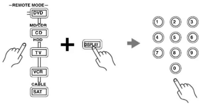
flowchart
graph TD
    A["−REMOTE MODE"] --> B["DVD"]
    B --> C["MD/CDR"]
    C --> D["CD"]
    D --> E["HDD"]
    E --> F["TV"]
    F --> G["VCR"]
    G --> H["CABLE"]
    H --> I["SAT"]

    J["+"] --> K["DISPLAY"]

    L["1"] --> M["2"] --> N["3"]
    O["4"] --> P["5"] --> Q["6"]
    R["7"] --> S["8"] --> T["9"]
    U["0"] --> V["1"] --> W["2"] --> X["3"]
Cable/PVR Combination
| Americast 0899 | |
| Digeo 1187 | |
| France Telecom | 1734 |
| General Instrument | 0476, 0810 |
| Jerrold | 0476, 0810 |
| Motorola | 1376, 0476, 0810, 1187 |
| Noos | 1624 |
| Pace | 1877, 0237 |
| Pioneer | 0877, 1877 |
| Scientific Atlanta | 0877, 1877 |
| Sony | 1006 |
| Thomson | 1734 |
| Zenith | 0899 |
Satellite Receiver
| @sat | 1300 |
| @Sky | 1334 |
| ADB 1259, 1367 | |
| Aiwa | 1514 |
| Alba | 1284 |
| AlphaStar | 0772 |
| Amstrad 0847, 0338 | |
| Ankaro 0713 | |
| Astro | 0173 |
| Atsat | 1300 |
| AtSky 1334 | |
| Austar | 0642, 1259 |
| Black Diamond 1284 | |
| Blaupunkt 0173 | |
| British Sky Broadcasting | 0847, 1175 |
| Bush | 1284, 1672 |
| Canal Digital | 0853 |
| Canal+ 0853 | |
| CanalSatellite | 0853, 1339, 1853 |
| Chaparral | 0216 |
| CNS | 1367 |
| Comag | 1412 |
| Crossdigital | 1109 |
| Cyrus 0200 | |
| D-box | 0873 |
| Dgtec 1242, 1542 | |
| Digenius | 0299 |
| Digiturk | 1076 |
| DirecTV | 1377, 0392, 0566, 0639, 1639, 1142, 0247, 0749, 1749, 0724, 0819, 1856, 1076, 1108, 1109, 1392, 1414, 1442, 1443, 1444, 1609, 1640 |
| Dish Network System | 1505, 1005, 0775, 1170, 1775 |
| Dishpro | 1505, 1005, 0775, 1775 |
| DMT | 1075 |
| DNT 0200 | |
| Dream Multimedia | 1237 |
| DSTV | 1433 |
| DX Antenna 1530 | |
| Echostar | 1505, 1005, 0775, 0853, 0610, 1200, 0713, 1170, 1775 |
| Expressvu | 0775, 1775 |
| Ferguson | 0711, 1291 |
| Foxtel | 0879, 1356 |
| Funai | 0338 |
| GbSAT 1214 | |
| GE | 0392, 0566 |
| General Instrument | 0869 |
| GOI | 0775, 1775 |
| Gold Box | 0853 |
| Goodmans | 1246, 1284 |
| Gradiente | 0887 |
| Grundig | 0847, 0173, 1291 |
| Satellite Receiver | |
| Hirschmann 0173 | |
| Hisense 1535 | |
| Hitachi | 0819, 1250, 1284, 1525 |
| HTS 0775, 1775 | |
| Hughes 0749, 1749, 1442 | |
| Hughes Network Systems | 1142, 0749, 1749, 1442, 1443, 1444 |
| Humax 1176, 1427, 1675 | |
| iLo 1535 | |
| Indovision 0887 | |
| ISkyB 0887 | |
| Jerrold 0869 | |
| JVC | 0775, 0492, 1170, 1531, 1775 |
| Kathrein | 0173, 0200, 0442, 0480, 0504, 0622, 0658, 1416, 1567 |
| Kreiselmeyer 0173 | |
| LG 1226, 1414 | |
| Lorenzen 0299 | |
| Magnavox 0724, 0722 | |
| Marantz 0200 | |
| Maspro 1530 | |
| Matsui 1284 | |
| Maximum 1334 | |
| MediaSat 0853 | |
| Medion | 1232, 1626 |
| Memorex 0724 | |
| Metronic | 0132, 0713, 1283, 1334 |
| Mitsubishi | 0749 |
| Morgan's | 0132 |
| Motorola | 0869 |
| Multichoice | 0879, 0642, 1433 |
| Myryad | 0200 |
| NEC | 1270, 1519 |
| Netsat | 0887 |
| Next Level | 0869 |
| Nikko | 0713 |
| Nokia | 0873, 1023, 1223, 1310 |
| OctalTV 1505 | |
| Opentel | 1232, 1412 |
| Optex | 1283 |
| Orbitech | 1100 |
| Pace | 0847, 0887, 0720, 1175, 0241, 0791, 1323, 1850 |
| Panasat 0879 | |
| Panasonic | 0247, 0701, 0847, 1304, 1404, 1526 |
| Paysat 0724 | |
| Philips | 1142, 0749, 1749, 0724, 0819, 1076, 0722, 0853, 0200, 1114, 0887, 0133, 0898, 1442, 1672 |
| Pioneer | 0853, 0329, 1308, 1442 |
| Plasmatic 0442 | |
| Satellite Receiver | |
| Preisner | 0132, 0262 |
| Proscan | 0392, 0566 |
| Proton 1535 | |
| QNS | 1367, 1404 |
| Radiola | 0200 |
| RadioShack | 0869 |
| RCA | 0392, 0566, 0855, 0143, 1291, 1392 |
| Rebox | 1214 |
| Sagem 0820, 1114, | 1690 |
| Samsung | 1377, 1142, 1276, 1108, 1109, 1442, 1458, 1570, 1609 |
| Sanyo | 1219 |
| Sat Control | 1300 |
| Schwaiger | 0504 |
| SEG | 1626 |
| Sharp | 1517 |
| Siemens | 0173 |
| SKY | 1856, 0847, 0887, 1175, 1848, 1850 |
| Skymaster | 0713, 1409 |
| Skyplus | 1334, 1412 |
| SM Electronic | 1200, 0713, 1409 |
| Smart | 0132 |
| Sony | 0639, 1639, 0847, 1524, 1558, 1640 |
| Star | 0887 |
| Star Choice | 0869 |
| Strong | 0879, 0132, 1146, 1300, 1409, 1626 |
| Supernova | 0887 |
| Teac | 1227 |
| TechniSat | 0262, 1099, 1100 |
| Technomate | 1610 |
| Technotrend | 1429 |
| Techwood 1284 | |
| Telestar | 1100, 1334 |
| Televisa 0887 | |
| Tevion | 1409 |
| Thomson | 0853, 0711, 1046, 1291, 1534, 1900 |
| Tiny | 1672 |
| Tivo | 1142, 1442, 1443, 1444 |
| Topfield 1206, 1208 | 1545 |
| Toshiba | 0749, 1749, 0790, 0819, 1285, 1516, 1530 |
| TPS | 0820 |
| UEC | 0879 |
| UltimateTV | 1392, 1640 |
| Uniden 0724, 0722, | 1521 |
| Universum | 0173 |
| US Digital | 1535 |
| USDTV | 1535 |
| Ventana | 0200 |
| Victor | 0492 |
| Voom | 0869 |
| Wisi | 0173 |
| Xsat 1323 | |
| Satellite Receiver | |
| Yes | 0887 |
| Zehnder | 1075, 1232, 1334, 1412 |
| Zenith | 1856 |
| DBS/PVR Combination | |
| @sat | 1300 |
| Atsat | 1300 |
| British Sky Broadcasting | 1175 |
| CanalSatellite | 1339 |
| Comag | 1412 |
| Digiturk | 1076 |
| DirecTV | 1377, 0392, 0639, 1142, 1076, 1392, 1442, 1443, 1444, 1640 |
| Dish Network System | 1505, 0775 |
| Dishpro 1505, 0775 | |
| Dream Multimedia | 1237 |
| Echostar | 1505, 0775, 0610, 1170 |
| Expressvu | 0775 |
| Foxtel | 1356 |
| GbSAT 1214 | |
| Hughes Network Systems | 1142, 1442, 1443, 1444 |
| Humax 1176, 1427, | 1675 |
| JVC | 1170 |
| Maximum 1334 | |
| Motorola | 0869 |
| Nokia | 1310 |
| Opentel | 1412 |
| Philips 1142, 1442 | |
| Proscan | 0392 |
| RCA | 1392 |
| Rebox | 1214 |
| Samsung 1442 | |
| SKY 1175, 1848, 1850 | |
| Skyplus | 1412 |
| Sony | 0639, 1640 |
| Star Choice | 0869 |
| Strong 1300 | |
| Thomson 1534, 1900 | |
| Topfield 1206, 1545 | |
| Zehnder | 1075, 1412 |
ONKYO CORPORATION
Sales & Product Planning Div. : 2-1, Nisshin-cho, Neyagawa-shi, OSAKA 572-8540, JAPAN Tel: 072-831-8023 Fax: 072-831-8124
Suite 1, Gregories Court, Gregories Road, Beaconsfield, Buckinghamshire, HP9 1HQ UNITED KINGDOM Tel: +44-(0)1494-681515 Fax: +44(0)-1494-680452
ONKYO CHINA LIMITED
Units 2102-2107, Metroplaza Tower I, 223 Hing Fong Road, Kwai Chung, N.T., HONG KONG Tel: 852-2429-3118 Fax: 852-2428-9039 http://www.ch.onkyo.com/

http://www.onkyo.com/
10603-2
647
- 7.1ch Home Theater System
- HT-S790
- Instruction Manual
- Contents
- WARNING:
- CAUTION:
- WARNING
- AVIS
- Important Safety Instructions
- Power
- Handling Notes
- For U.S. models
- FCC Information for User CAUTION:
- NOTE:
- For Canadian Models
- Using Close to a TV or Computer
- Input Signal Warning
- Speaker Sets A and B
- Speaker Set A: Main Room
- Front left and right speakers (SKF-540F)
- Center speaker (SKC-540C)
- Subwoofer (SKW-540)
- Surround back left and right speakers (SKB-540)
- Surround left and right speakers (SKM-540S)
- Amplifier
- Processing
- Audio/Video
- Tuner
- Remote Controller
- Speaker
- \*2 DOLBY DIGITAL·EX PROLOGIC IX
- \*3 dts 96 24 ES NEOS
- \*4 neural SURROUND.
- \*5 ((XM)) READY
- Getting Started in Five Easy Steps
- Hookup
- Turning On
- First Time Setup
- Playing Your AV Components
- Using the Listening Modes
- Introduction
- Connection
- Turning On & First Time Setup
- Basic Operation
- Enjoying the Listening Modes
- Advanced Operation
- Front Panel
- Display
- Rear Panel
- Installing the Batteries
- Notes:
- Aiming the Remote Controller
- Using the Remote Controller
- ■ RECEIVER/TAPE Mode
- ■ DVD and CD/MD/CDR/HDD Modes
- ■ TV, VCR and SAT/CABLE Modes
- RECEIVER/TAPE Mode
- STEREO button
- SURROUND button
- ■ Buttons used when the TUNER input is selected
- North American model only
- ■ Buttons used when the TAPE input is selected
- DVD Mode
- CD/MD/CDR/HDD Mode
- ① STANDBY/ON indicator
- ② OUTPUT LEVEL control (36)
- ③ LINE INPUT (19)
- ④ POWER switch (Not North American model) (34)
- ■ Attaching and detaching the speaker grilles
- Speaker Connection Precautions
- Connecting Speaker Set A
- Connecting Speaker Set B (sold separately)
- Connecting Antennas
- Connecting the Indoor FM Antenna
- Attach the FM antenna, as shown.
- ■ American Model
- ■ Other Models
- Use thumbtacks or something similar to fix the FM antenna into position.
- Connecting the AM Loop Antenna
- Assemble the AM loop antenna, inserting the tabs into the base, as shown.
- Connect both wires of the AM loop antenna to the AM push terminals, as shown.
- Connecting an Outdoor FM Antenna
- ■ Using a TV/FM Antenna Splitter
- Connecting an Outdoor AM Antenna
- Connecting Your Components
- About AV Connections
- Optical Digital Jacks
- AV Connection Color Coding
- AV Cables and Jacks
- Connecting Audio and Video Signals to the AV Receiver
- Which Connections Should I Use?
- Video Connection Formats
- Audio Connection Formats
- Connecting a TV or Projector
- Step 1: Video Connection
- Step 2: Audio Connection
- Connecting a DVD player
- Hooking Up the Multichannel DVD Input
- Connecting a VCR or DVD Recorder for Playback
- Connecting a VCR or DVD Recorder for Recording
- Connecting a Camcorder, Games Console, or Other Device
- Connecting a Satellite, Cable, Set-top box, or Other Video Source
- Connecting a CD Player or Turntable
- ■ CD Player or Turntable (MM) with Built-in Phono Preamp
- Step 1:
- ■ Turntable (MM) with no Phono Preamp Built-in
- ■ Turntable with an MC (Moving Coil) Cartridge
- Connecting an HDD-compatible Component
- ■ For HDD-compatible components that support video
- ■ For HDD-compatible components that don't support video
- Connecting a Cassette, CDR, MiniDisc, or DAT Recorder
- Connecting the Power Cord of Another Component
- Connecting Onkyo Components
- ■ Auto Power On/Standby
- ■ Direct Change
- ■ Remote Control
- Connecting the Power Cord
- Turning On and Standby
- 1
- Press the [STANDBY/ON] button.
- Smooth Operation in a Few Easy Steps
- ■ Have you connected a component to a digital audio input?
- ■ Have you connected an Onkyo MD recorder, CD recorder, or next generation HDD-compatible component?
- Testing the speakers
- Assigning Digital Inputs to Input Sources
- Changing the Input Display
- Basic AV Receiver Operation
- Using the Multichannel DVD Input
- Press the [RECEIVER] REMOTE MODE button, followed by the [MULTI CH] button.
- Displaying Source Information
- Interpreting Surround Channel Information
- ■ AM Frequency Step Setup (not North America)
- Tuning into AM/FM Radio Stations
- ■ Auto Tuning Mode
- ■ Manual Tuning Mode
- Tuning into Weak FM Stereo Stations
- ■ Tuning into Stations by Frequency
- Presetting AM/FM Stations and XM Channels
- ■ Selecting Presets
- ■ Deleting Presets
- Listening to XM Satellite Radio® (North American Models Only)
- Important XM Radio Information
- About XM Radio:
- About XM Canada:
- A warning against reverse engineering:
- Connecting the XM Passport System
- Selecting XM Satellite Radio
- Signing Up for XM Satellite Radio
- Selecting XM Radio Channels
- ■ Channel Search Mode
- ■ Category Search Mode
- ■ Direct Tuning
- Positioning the XM Passport System
- XM Radio Messages
- Common Functions
- Setting the Display Brightness
- Adjusting the Bass and Treble
- ■ Bass
- Treble
- Muting the AV Receiver
- Using the OptiResponse Equalizer
- Using the Sleep Timer
- Press the remote controller's [SLEEP] button repeatedly to select the required sleep time.
- Using Headphones
- Adjusting Speaker Levels
- ■ Speaker Set B
- ■ Headphones
- Selecting Listening Modes
- ■ [PURE AUDIO] button (not North American model)
- ■ [STEREO] button
- ■ LISTENING MODE [◀] buttons
- About the Listening Modes
- Pure Audio (not North American models)
- Direct
- Stereo
- Mono
- Dolby Pro Logic IIx
- Dolby Pro Logic II
- - PLIIx Movie
- - PLIIx Music
- - PLIIx Game
- Dolby Digital
- Dolby Digital EX DTS+Dolby EX
- Dolby Digital+PLIIx Music DTS+PLIIx Music
- Dolby Digital+PLIIx Movie DTS+PLIIx Movie
- DTS
- DTS 96/24
- DTS-ES Discrete
- DTS-ES Matrix
- DTS Neo:6
- - Neo:6 Cinema
- - Neo:6 Music
- Neural Surround
- (North American models only)
- Onkyo Original DSP Modes
- Mono Movie
- Orchestra
- Unplugged
- Studio-Mix
- TV Logic
- All Ch Stereo
- Full Mono
- Using the Late Night Function (Dolby Digital only)
- Press the [RECEIVER] REMOTE MODE button, and then press the [L NIGHT] button repeatedly to select:
- Using the CinemaFILTER
- Press the [RECEIVER] REMOTE MODE button, and then press the [CINE FLTR] button repeatedly to select:
- Using the Audio Adjust Settings
- Press the [RECEIVER] button followed by the [SETUP] button.
- Use the Up and Down [][ ]▼ buttons to select "4. Audio Adjust," and then press [ENTER].
- Use the Left and Right [◀] ▶ buttons to change the setting.
- Press the [SETUP] button.
- Input Channel Settings
- ■ Multiplex
- ■ Mono (2ch)
- PLII and PLIIx Music Mode Settings
- Panorama
- ■ Dimension
- ■ Center Width
- DTS Neo:6 Music Mode Setting
- ■ Center Image
- Dolby Digital EX Input Signal Setting
- ■ Dolby EX
- Multichannel Subwoofer Setting
- ■ SW Sens
- Speaker Distance
- Speaker Levels
- 2
- 3
- 4
- 5
- 6
- Speaker Configuration
- 7
- Use the Down [button to select "Surr Back," and use the Left and Right [] buttons to select Small, Large, or None.
- 8
- Use the Down [button to select "Surr Back Ch," and use the Left and Right [ ] buttons to select 2ch or 1ch.
- Crossover Frequency
- 9
- Use the Down [button to select "Crossover," and then use the Left and Right [button] to select a crossover frequency.
- Double Bass
- 10
- Use the Down [ ] button to select "Double Bass," and then use the Left and Right [ ] ▶ buttons to select:
- 11
- Digital Input Signal Formats
- Correcting Sound and Picture Sync
- Recording the Input Source
- Recording Audio and Video from Separate Sources
- Controlling Other Components
- Entering Remote Control Codes
- Look up the appropriate remote control code in the separate Remote Control Codes list.
- Remote Control Codes for Onkyo Components Connected via RI
- Resetting REMOTE MODE Buttons
- Resetting the Remote Controller
- Power
- Can't turn on the AV receiver
- The AV receiver turns off as soon as it's turned on
- Audio
- There's no sound or it's very quiet
- Only the front speakers produce sound
- Only the center speaker produces sound
- The surround speakers produce no sound
- The center speaker produces no sound
- The surround back speakers produce no sound
- The subwoofer produces no sound
- Speaker set B produces no sound
- There's no sound with a certain signal format
- Can't get 6.1- or 7.1-channel playback
- The volume cannot be set to 79
- Noise can be heard
- The Late Night function doesn't work
- The multichannel DVD input doesn't work
- About DTS signals
- Video
- There's no picture
- Reception is noisy, stereo FM reception suffers from hiss, or the FM STEREO indicator doesn't appear
- The remote controller doesn't work
- Can't control other components
- Recording
- Can't record
- Others
- The sound changes when I connect my headphones
- The display doesn't work
- How do I change the language of a multiplex source
- The functions don't work
- Memory Backup
- The following settings can be made for the S-Video and composite video inputs
- • Video Attenuation
- - Outputting S-Video Sources from the Composite Video Outputs
- Amplifier Section
- Video Section
- Tuner Section
- FM
- ■ AM
- General
- ■ Video Inputs
- ■ Video Outputs
- ■ Audio Inputs
- ■ Audio Outputs
- ■ Powered Subwoofer (SKW-540)
- ■ Front Speaker (SKF-540F)
- ■ Center Speaker (SKC-540C)
- ■ Surround Speaker (SKM-540S/SKB-540)
- ONKYO CORPORATION
- ONKYO CHINA LIMITED
- Remote Control Codes
Brand : ONKYO
Model : HT-S7400
Category : Uncategorized