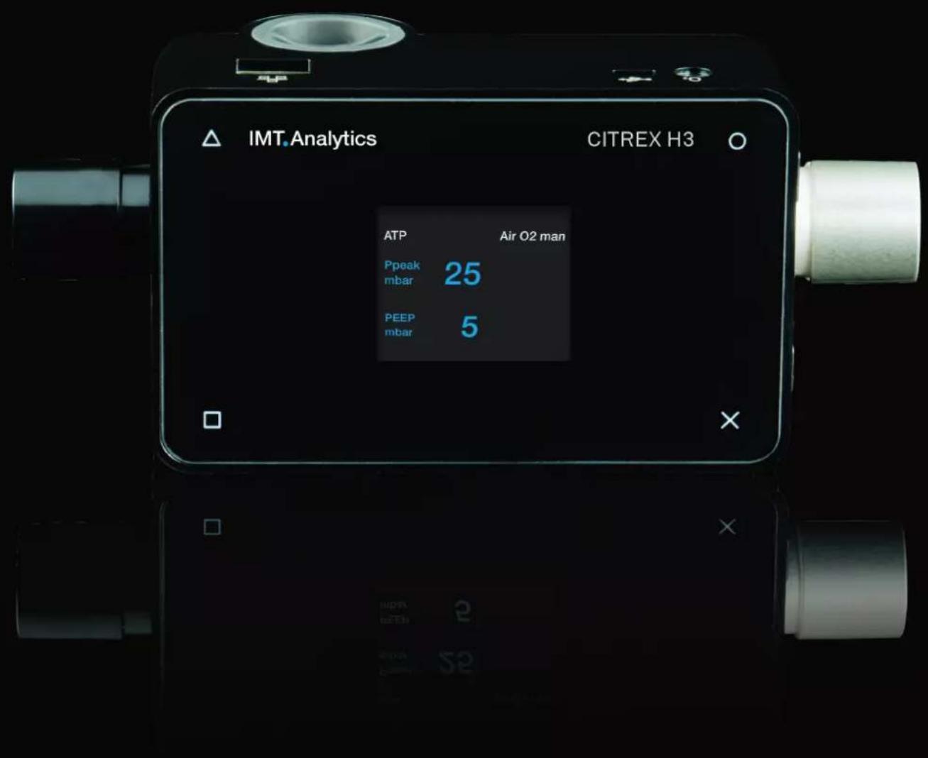
Citrex H3 - Measuring device Rigel Medical - Free user manual and instructions
Find the device manual for free Citrex H3 Rigel Medical in PDF.

| Product Type | Measuring device for flow, pressure, volume, and ventilation parameters |
| Brand | Rigel Medical (manufactured by IMT Analytics) |
| Model | Citrex H3 |
| Dimensions (W x D x H) | 11.4 x 7 x 6 cm |
| Weight | 0.38 kg |
| Power Supply Input | 100-240 VAC, 50-60 Hz via USB; 5 VDC |
| Battery Operating Time | 4 hours |
| Display | 1.7\" color display |
| Interfaces | Ethernet, USB Mini-B, microSD card slot, O2 sensor interface |
| Flow Measurement Range | ±300 sL/min (air, N2, O2/air mixtures); ±80 sL/min (N2O/O2) |
| Flow Accuracy | ±2% of reading or ±0.1 sL/min (air); ±4% or ±0.3 sL/min (N2O/O2) |
| Pressure Measurement Range (channel) | -50 to 150 mbar |
| Pressure Accuracy (channel) | ±0.75% of reading or ±0.1 mbar |
| Barometric Pressure Range | 500-1150 mbar |
| Barometric Accuracy | ±1% of reading or ±5 mbar |
| Volume Measurement Range | 0-10 sL |
| Volume Accuracy | ±2% of reading or ±0.02 sL |
| Oxygen Measurement Range (optional) | 0-100% |
| Oxygen Accuracy | ±1% O2 (absolute) |
| Gas Temperature Measurement | 0-50°C, accuracy ±1.75% or ±0.5°C |
| Supported Gas Types | Air, O2, Air/O2 mixtures, N2O/O2 mixtures |
| Gas Standards | ATP, ATPD, ATPS, AP21, STP, STPH, BTPS, BTPS-A, BTPD |
| Ventilation Parameters Measured | Rate, tidal volume, minute volume, peak flow, pressures (PEEP, mean, peak), I:E ratio, inspiratory time |
| Calibration Interval | Annually |
| Operating Temperature | 15-40°C (59-104°F) |
| Storage Temperature | -10 to 60°C (14-140°F) |
| Humidity (Operating) | 10-90% RH |
| Humidity (Storage) | 5-95% RH |
| Safety Standards | CE, CSA, UL 61010-1, IEC 61010-1, EMC IEC 61326-1 |
| Intended Use | Testing and calibration of ventilators and anesthetic equipment in laboratory environment |
| Service Life | 10 years |
Frequently Asked Questions - Citrex H3 Rigel Medical
User questions about Citrex H3 Rigel Medical
0 question about this device. Answer the ones you know or ask your own.
Ask a new question about this device
Download the instructions for your Measuring device in PDF format for free! Find your manual Citrex H3 - Rigel Medical and take your electronic device back in hand. On this page are published all the documents necessary for the use of your device. Citrex H3 by Rigel Medical.
USER MANUAL Citrex H3 Rigel Medical
the art of measuring
User Manual
CITREX H3
IMT.Analytics
IMT Analytics AG
Gewerbestrasse 8
9470 Buchs (SG)
Switzerland
www.imtanalytics.com
Table of Contents
1 Introduction 5
2 Intended use 6
3 Safety instructions 7
3.1 Representation of hazards, cautions and notes 7
3.2 Personnel 7
3.3 Responsibility and guarantee 7
3.4 Service life 7
4 Symbol explanation 8
5 Start-up 9
5.1 Power supply 10
5.2 Mechanical connectors 11
5.2.1 Flow channel 11
5.2.2 Oxygen sensor (option) 12
5.2.3 Installing the oxygen sensor 12
5.3 Electrical interfaces 14
5.4 Change CITREX battery 15
6 Operation 16
6.1 Switching the device on/off 16
6.2 Screen lock 16
6.3 Dim screen 16
6.4 User controls 17
6.5 Settings 18
6.5.1 Info display 18
6.5.2 Battery indicator 18
6.5.3 Ethernet interface 18
6.5.4 Trigger 19
6.5.5 Gas standard 19
6.5.6 Gas type 20
6.5.7 Gas humidity 20
6.5.8 Oxygen calibration (optional) 20
6.6 Numerical readings 21
6.7 Filter 21
6.8 Change parameters and units 22
7 Calibration
7.1 Zero point 23
7.2 Oxygen (O _2 ) calibration 23
7.2.1 Calibration with air 24
7.2.2 Calibration with oxygen and air 24
8 Connecting the device
8.1 General measurement setup 25
8.2 Measurement setup for checking ventilators 26
9 Configuration tool 27
9.1 PC minimum requirements 27
9.2 Web server 27
9.2.1 Default 27
9.2.2 Configured 28
9.2.3 DHCP 28
9.2.4 Enable oxygen option 28
10 Servicing and care 29
10.1 Preventive cleaning and servicing operations 29
10.1.1 During operation 29
10.1.2 Every 4 weeks 29
10.1.3 Every 12 months 29
11 Accessories and spare parts 30
11.1 Accessories table 30
12 Disposal 31
13 Directives and approvals 32
14 Specifications 33
14.1 Measurement parameter 33
14.2 Gas type 36
14.3 Power supply 36
14.4 Battery operation 36
15 Appendix 37
15.1 Principle of flow measurement 37
15.2 Trigger 37
15.2.1 Flow trigger 38
15.2.2 Pressure trigger 38
15.2.3 Base flow 38
15.2.4 Delay 38
15.3 Measurement parameters and units 39
15.4 Gas standards for flow and volume readings 40
15.5 Conversion factors 41
15.6 List of tables 42
15.7 List of figures 42
15.8 Index 43
1 Introduction
CITREX H3 was developed in order to measure flow and various pressures and thus calculate various ventilation parameters. CITREX H3 is a compact, mobile and easy-to-operate measuring instrument. The device was developed in order to calibrate gas flows and pressures by simple means. With the oxygen option it is possible to measure oxygen concentrations.
The descriptions and instructions in this manual refer to the product CITREX H3. In this User Manual the unit "sL/min" is based on ambient conditions of 0°C and 1013.25 mbar in accordance with DIN 1343.
This documentation applies to the following versions:
CITREX H3 software: 4.4.000
CITREX H3 hardware: 4.0
In the case of older or newer versions there may be discrepancies in relation to this User Manual.
Subject to technical modifications without notice.

To avoid possible injuries, please read all the safety instructions before you use the product.

The device is not intended for use outside a building.
2 Intended use

This product is intended for testing and calibration purposes on medical devices or systems that generate gas flows or gas pressures. That includes ventilators and anaesthetic equipment. The user of the device has received training on how to use medical equipment and can perform repairs, maintenance and servicing on medical devices. CITREX H3 can be used in hospitals, in clinics, at device manufacturers or at independent service companies that perform repairs or servicing operations on medical devices.
CITREX H3 is intended for use in a laboratory environment. It may only be used outside the nursing sector. It must not be used directly on patients or devices that are connected to patients. The measuring instrument CITREX H3 is intended for over-the-counter sale.
With CITREX H3 you have the solution for measurements in the following areas:
- Flow
- Pressure
• Volume - Ambient pressure
- Temperature
In addition, various ventilation parameters can be measured:
- Ventilation rate
• Time - Ratio
- Tidal volume
- Minute volume
- Peak flow
- Pressure
- Trigger

CITREX H3 is a measuring instrument for checking and calibrating ventilators and anaesthetic equipment. It must not be used for patient monitoring. During patient treatment by the ventilator it is not allowed to connect to CITREX H3.
It is not allowed to measure liquids with CITREX H3.
3 Safety instructions
Please read all the safety instructions carefully before you use CITREX H3.
3.1 Representation of hazards, cautions and notes
This User Manual uses the representation below to specifically draw attention to residual risks during intended use and emphasise important technical requirements.
Information and/or instructions and prohibitions to prevent damage of any kind, as well as useful tips and information for handling the device, will be indicated by the following icon:

3.2 Personnel

Work on and with CITREX H3 may only be performed by persons who have undergone appropriate technical training and have the necessary experience.
3.3 Responsibility and guarantee
The manufacturer accepts no responsibility or guarantee and will exempt itself from liability claims accordingly if the operator or any third parties:
- Fail to use the device in accordance with its intended use.
- Disregard the specifications.
- Tamper with the device in any way (conversions, modifications or the like).
- Operate the device with accessories that are not listed in the associated sets of product documentation.

Although the device meets high quality and safety standards and it has been constructed and tested according to the current state of the art, it is not possible to rule out the risk of injuries with serious consequences if the device is used in non-compliance with the intended use (improperly) or is misused.
Therefore please read through this User Manual carefully and keep this documentation in a readily accessible place close to your device.
3.4 Service life
The maximum service life of the device has been specified as 10 (ten) years, provided it is handled properly in accordance with this User Manual.
4 Symbol explanation
The symbols listed below may appear on the packaging material, on the device rating plate and in the User Manual of the CITREX H3 measuring instrument.
 | USB interface |
| SN BBXXXX Serial number | |
 | Ethernet interface |
 | On/Off button |
 | SD card |
 | Fragile contents |
 | Keep dry |
 | Read the User Manual |
 | The device must not be disposed of in household waste |
 | The device is CE approved |
 | Caution: observe the safety instructions in the User Manual |
 | Reusable packaging |
 | Manufacturer's specification and date of manufacture |
 | Keep away from heat |
 | Temperature range for storage and transport |
 | CSA monogram with C/US indicator |
| --- | Direct current |
Table 1: Symbol explanation
5 Start-up
 | CITREX H3 |
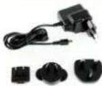 | Power supply plug with country-specific adapters |
 | USB cable |
 | MicroSD card |
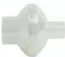 | Dust filter RT019 |
 | Network cable |
Table 2: Scope of delivery
5.1 Power supply
CITREX H3 can be operated from the mains or from the integrated battery.
Power can be supplied via the USB port (Mini-B) on the top of CITREX H3. Use the power supply unit included to charge the battery or operate the device via the USB port. You will find more information about power supply in the section "Electrical interfaces".
During the charging process a green battery symbol is lit on the front.
Please connect the power supply unit included to a voltage of 100 VAC to 240 VAC with a frequency of 50 Hz to 60 Hz.
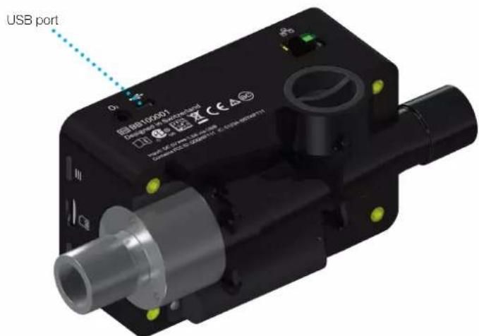
Figure 1: Power supply

Before switching on, make sure the operating voltage of the power supply unit agrees with the local mains voltage. You will find this information on the rating plate on the back of the power supply unit. When operating CITREX H3 via the USB port only use the original power supply unit included!

The device indicates visually and audibly when the battery has to be charged. Please do not store the battery in a depleted state.
Caution: depletion can damage the battery beyond repair!
5.2 Mechanical connectors
5.2.1 Flow channel
The flow channel can be used bidirectionally. The positive flow direction is from left to right, viewed from the front of the device. The measurements of volume, flow, gas temperature, oxygen (option) and channel pressure are taken in the flow channel. The values, and the ventilation parameters calculated from them, can be displayed on the screen. You will find the relevant setting options in the section "Operation".
| Flow (air) Measuring range ±300sL/min | ||
| Accuracy ± 2% of reading or ± 0.1 sL/min | ||
| Volume Measuring range 0–10sL | ||
| Accuracy ± 2% of reading or ± 0.02sL | ||
| Temperature Measuring range 0–50°C | ||
| Accuracy ± 1.75% of reading or 0.5°C | ||
| Oxygen Measuring range 0–100% | ||
| Accuracy ± 1% O | 2 | |
| Pressure in flow channel | Measuring range -50 – 150 mbar | |
| Accuracy ± 0.75% of reading or ± 0.1 mbar | ||
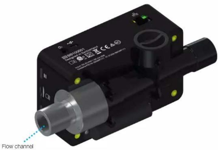
Figure 2: Flow channel
5.2.2 Oxygen sensor (option)
CITREX H3 can be fitted with an oxygen sensor. The option is enabled using the configuration tool. You will find further information on the configuration tool in the section "Configuration tool".
After enabling, oxygen concentration can be measured in the flow channel. To do so, an oxygen sensor is screwed into the appropriate port. The oxygen sensor has to be connected to the measuring instrument using the cable included. The following steps explain how to install and replace the oxygen sensor.
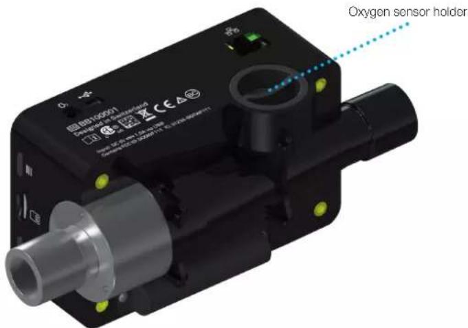
Figure 3: Oxygen sensor holder
Measuring range 0–100%
Accuracy ±1% O _2 (absolute)
5.2.3 Installing the oxygen sensor
- Remove the protective cap from the sensor port of the device.
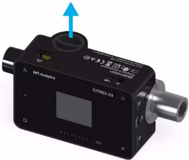
Figure 4: Protective cap
- Screw the oxygen sensor clockwise into the appropriate port. Make sure the sensor seals off the port and there is no leak.
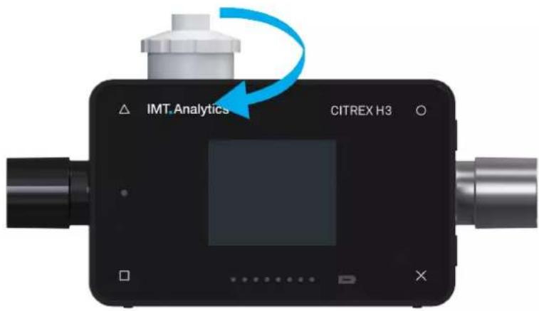
Figure 5: Screwing in the oxygen sensor

- Connect the cable included to the oxygen sensor by pushing the cable into the hole at the top of the sensor until the cable locks into place. Connect the other end of the cable to CITREX H3 by inserting it into the hole provided, which is labelled "O₂".
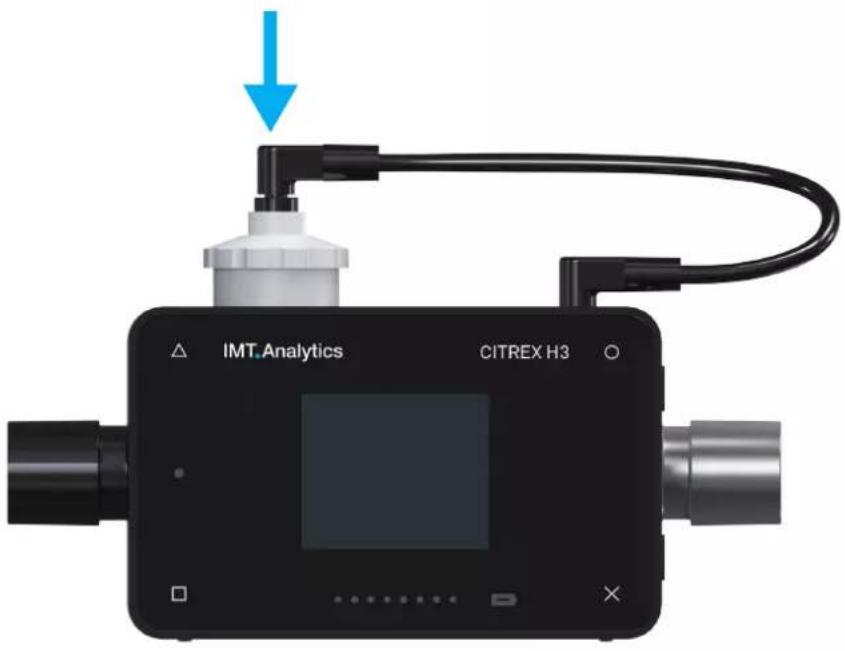
Figure 6: Oxygen sensor cable
- Perform an oxygen calibration. The calibration procedure is described in the section "Calibration". Calibration ensures that the measured values of the new sensor are correct.
5.3 Electrical interfaces
Figure 7 shows the available electrical interfaces of CITREX H3.
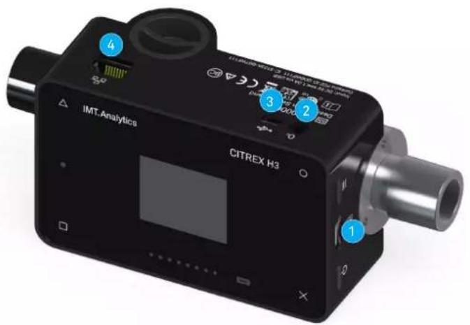
Figure 7: Electrical interfaces
| 1 MicroSD card slot | The firmware of CITREX H3 is stored on the microSD card. It also contains customised configurations. | |
| 2 O2interface The optional oxygen sensor is connected to CITREX H3 via the O_2 interface. You will find further information on this in the section "Oxygen sensor". | ||
| 3 USB port The USB port is used to operate the device from the mains power supply and to charge the device battery. It is a "USB Mini-B port". | ||
| 4 Ethernet The Ethernet interface is used to configure the device and it is used as a data interface. | ||
Table 3: Description of electrical interfaces
5.4 Change CITREX battery
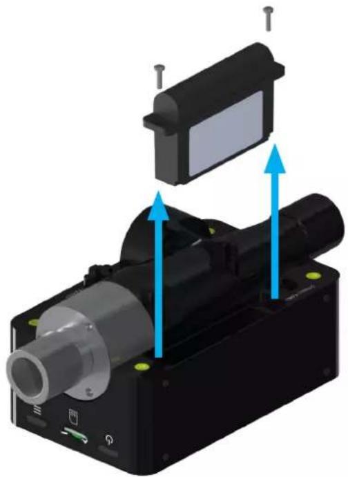
The battery of CITREX H3 can be changed by the user. To do so, undo and remove the two screws on the back of the device. Then the battery can be removed and replaced. Check whether the new battery has been inserted properly. For this purpose the terminals must be opposite one another.
natural_image
3D mechanical assembly diagram showing a motor with blue directional arrows indicating motion or force (no text or symbols)Figure 8: Change battery
6 Operation
This section describes how to use the device and what possible uses there are.
6.1 Switching the device on/off
The device is switched on and off at the On/Off button. Figure 8, section "User controls", shows where this button is located on the device. To switch CITREX H3 on you must press the On/Off button briefly. You will hear an audible signal. To switch the device off you must press the On/Off button for about 1 second. If the device can no longer be controlled, you have the option of pressing the On/Off button for about 6 seconds. The device is then forced to shut down.
6.2 Screen lock
Press the context button on the side of the device for 2 seconds. The screen shows a message indicating that the screen is locked. To unlock the screen, press and hold down the context button or one of the four buttons on the front for 2 seconds.
6.3 Dim screen
If the device is not operated by the user, the display of CITREX H3 shuts down after about one minute and the four buttons start to flash. As soon as a button is pressed, the screen comes on again.
The setting for how long it takes until the display is dimmed can be customised using the configuration tool. You will find further information on this in the section "Configuration tool".
6.4 User controls
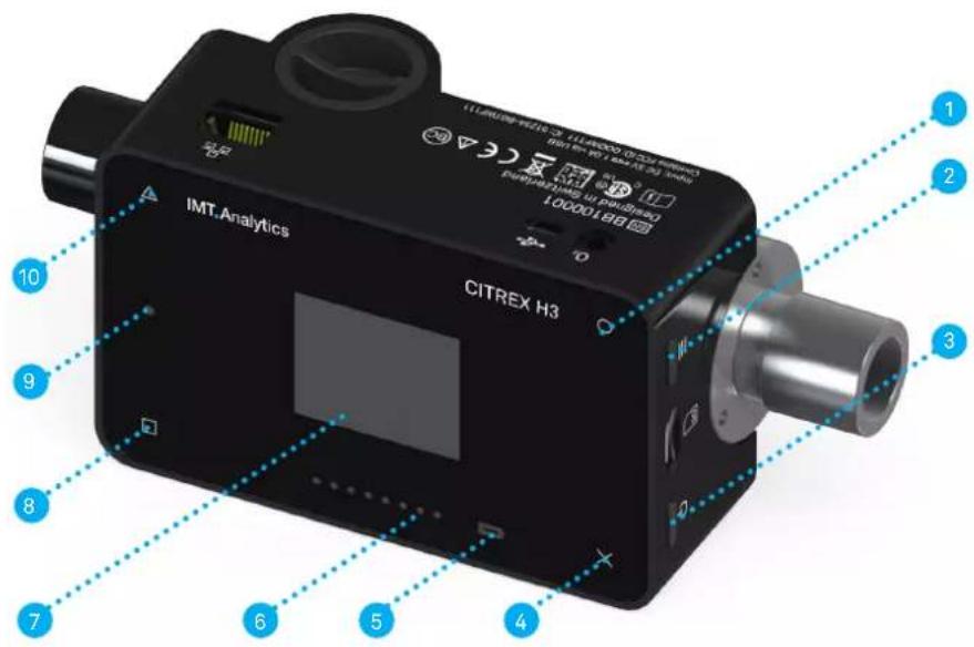
Figure 9: User controls
| 1 Change, Edit |
| 2 Context button; long press: key lock on/off |
| 3 On/Off button |
| 4 Menu button; zero point adjustment |
| 5 Charge indicator |
| 6 Flow direction indicator |
| 7 Screen |
| 8 Display readings and scroll forward |
| 9 Malfunction indicator |
| 10 Display readings and scroll back |
Table 4: User controls
6.5 Settings
With the x button you access the "Settings" menu. By pressing the button more than once you can view the various settings of the measuring instrument.
6.5.1 Info display
This display provides information about the owner, the company, the next recommended calibration, the software version and the hardware revision. Settings concerning the owner can be edited with the configuration tool.
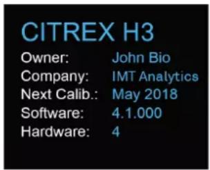
Figure 10: Info display
6.5.2 Battery indicator
The battery indicator informs you about the level of the battery charge.

Figure 11: Battery indicator
6.5.3 Ethernet interface
Here it is possible to make various settings for the network connection. With the ○ button you can choose between the options "DHCP Client", "Default" and "Configured". The setting does not have to be confirmed and it is enabled as soon as it is visible on the screen. More information about the settings is available in the section "Web server".

Figure 12: Ethernet interface
6.5.4 Trigger
With the trigger settings the start and end points of a ventilation parameter are defined. Two preset triggers are available. With the ○ button you can select the trigger "Adult" or "Pediatric". The trigger settings do not have to be saved and they are enabled as soon as they are displayed on the screen. It is possible to differentiate between flow trigger, pressure trigger and external trigger.
The settings can be changed with the configuration tool. You will find further information on this in the section "Configuration tool".
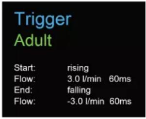
Figure 13: Trigger
The preset trigger settings are defined as follows.
| Adult Pediatric | ||
| Start 3L/min | Rising edge | 1 L/minRising edge |
| Stop -3L/min | Falling edge | -1 L/minFalling edge |
| Delay 60ms60ms | ||
| Base flow 0L/min 0L/min | ||
Table 5: Trigger settings
6.5.5 Gas standard
The CITREX H3 measuring instrument can convert gas flow and volume readings to various gas standards and display them. Care must be taken to ensure that on the measuring instrument the same gas standard is set as the one on the device being tested. With the O button you can switch between the various gas standards. As soon as a gas standard is displayed, it is enabled. There is a list of available gas standards in the Appendix in the section "Gas standards for flow and volume readings".

Figure 14: Gas standard
6.5.6 Gas type
Under this menu item the gas type to be measured can be set. With the O button you can switch between gas types. The gas type indicated is enabled and does not have to be saved. In the section "Gas type" there is an overview of available gas types. Gas types with adjustable oxygen concentrations, e.g. "Air O _2 manual", can be changed with the configuration tool.

Figure 15: Gas type
6.5.7 Gas humidity
The gas humidity of the gas being measured can be set. This has an impact on gas flow measurement. With the ○ button the gas humidity can be changed in steps of 10. The value is enabled as soon as it is displayed on the screen.

Figure 16: Gas humidity
6.5.8 Oxygen calibration (optional)
Oxygen calibration is only available if the oxygen option has been enabled. The process of oxygen calibration is described in the section "Calibration". With the ○ button you can choose between one-point calibration and two-point calibration. Press the △ button to start calibration.

Figure 17: O_2 calibration
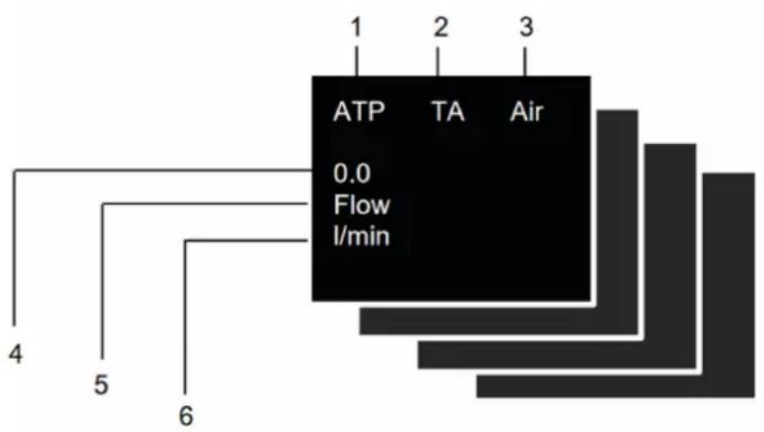
6.6 Numerical readings
With the □ button on the front of CITREX H3 you can display the various numerical readings. If you press more than once, the view on the screen changes. The different views can be configured by web server. The web server and how to make the settings are explained in the section "Web server".
flowchart
graph TD
    A["ATP 0.0 Flow l/min"] --> B["1"]
    A --> C["2"]
    A --> D["3"]
    A --> E["4"]
    A --> F["5"]
    A --> G["6"]
Figure 18: Numerical readings
| 1 Gas Standard The measured volume readings or gas flow readings can be displayed with various gas standards. There is a list of standards in the Appendix in the section "Gas standards for flow and volume readings". | |
| 2 Trigger signal | The icon appears as soon as a trigger condition is fulfilled. This means that the time of appearance of the indicator is identified as the start of inspiration. The indicator appears for 0.5 seconds. If this signal is not displayed, the trigger settings should be adjusted for the current ventilation mode. |
| 3 Gas type The gas type currently set is displayed as text. It can be customised on the device under Settings. | |
| 4 Reading This shows the current reading in the selected unit of measurement. | |
| 5 Measurement parameter | Indicates the measurement parameter currently selected. Measurement parameters can be changed in configuration; see section "Configuration tool". |
| 6 Measuring Unit | Indicates the unit of measurement currently selected. Units of measurement can be changed in configuration; see section "Configuration tool". |
Table 6: Numerical values
6.7 Filter
The screen of CITREX H3 is refreshed every 0.5 s. The recording of readings takes place every 5 ms. Since CITREX H3 can record and display readings very quickly, it is advisable to filter the readings. This is performed using a mean value. The extent to which a reading is filtered can be set using the configuration tool.
The following filters are available:
- No filter (indication of the last value measured without any threshold)
- Low (mean above 240 ms)
• Medium (mean above 480 ms)
• High (mean above 960 ms)
6.8 Change parameters and units
The "high" filter is set by default.
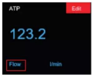
If the context button (≡) is pressed twice in succession, "Edit Mode" is enabled. This is indicated by a red icon on the screen. The parameter or unit in the red frame can be changed with the □ icon or the ○ icon. The Δ icon allows you to jump to the next element. If the context button or the × button is pressed once, you exit "Edit Mode"
7 Calibration
The various calibration options with CITREX H3 are described in this section. To avoid incorrect measurements you must adhere to the procedures described here.
7.1 Zero point
This adjustment is necessary if indication of the channel pressure sensor ( P_channel ) or a flow through open connection ports shows a value greater or less than zero. This can occur if there are considerable temperature fluctuations, or after the warming-up time. Zero calibration resets all values to zero. To perform zero calibration you must remove all connected tubes from the device. Press the × icon and keep it pressed for approx. 3 seconds. The screen shows a message "Zero Offset – Calibrating, please wait".
Zero Offset
Calibrating, please wait...
Figure 19: Zero calibration
7

When you have switched on the device, individual displays may deviate slightly from the zero point until operating temperature has been reached. Zero calibration should never be performed with the device cold. Warming-up time is approx. 10 minutes.

During zero calibration there must be no pressure being applied to a connection port, and care must be taken to ensure that there is no flow through the flow channel.
7.2 Oxygen (O _2 ) calibration
There are two different methods of calibrating the oxygen cell. The variant in which the oxygen cell is calibrated with air only takes about two minutes. The second variant consists of calibrating the oxygen cell with air and 100% oxygen. This so-called two-point calibration adjusts the oxygen sensor more accurately and takes about four minutes. Calibration can be selected by pressing the × button more than once.
7.2.1 Calibration with air
Calibration is only available if the oxygen option has been enabled. Make sure air is flowing through the flow channel at a rate of at least 30 L/min. To start calibration, press the × button until you see the menu item
"O₂ Calibration". With the ○ button you can switch between air and air and oxygen (O₂). Select the ○ button until "Air" appears on the screen in green letters. To start calibration, press the △ button. It takes about 120 seconds before calibration is completed.


Figure 20: Screen displays "Calibration Air"
7.2.2 Calibration with oxygen and air
For calibration of the oxygen cell with oxygen and air a gas flow of 30 L/min is used in each case. Press the × button until you see the menu item "O₂ Calibration". With the ○ button you can switch between air and air and oxygen (O₂). Press the ○ button until the screen shows "O₂ and Air" in green letters. To start calibration, press the △ button. Calibration for air and oxygen takes 120 seconds for each one.


Figure 21: Screen displays "Calibration Oxygen and Air"
8 Connecting the device
The measurement setup for CITREX H3 has an impact on flow measurement. To obtain results that are as accurate as possible, comply with the instructions in this section. It is important to ensure that the tubing in the measurement setup does not have any radii, kinks or dents. You are also recommended to always use the dust filter included.

The measured gases must be free of oil, grease and dust.
8.1 General measurement setup
The general measurement setup applies to gas flow measurement. The RT019 filter included and a short piece of tubing must be used. This ensures laminar flow to the flow sensor unit. The filter also prevents dust, oil and grease from contaminating the CITREX H3 measuring instrument and thus prevents discrepancies in measurement results. The measurement setups shown below are dependent on the direction of gas flow being measured.
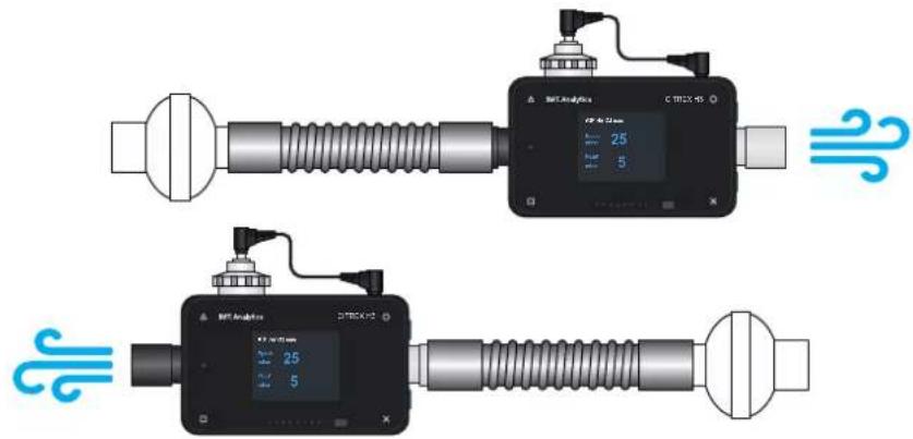
Figure 22: General measurement setup
The measurement setups listed below are unsuitable and produce inaccurate measurement results. Kinks, tees and angle pieces should be avoided in the flow channel. They cause turbulence in the gas being measured and hence inaccurate or incorrect measurement results.
Bad setup: Kinks, tees, angle pieces at the device inlet
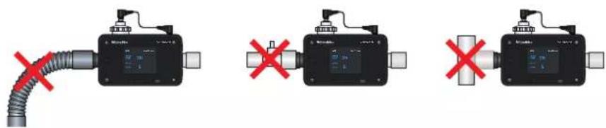
Figure 23: Bad setup
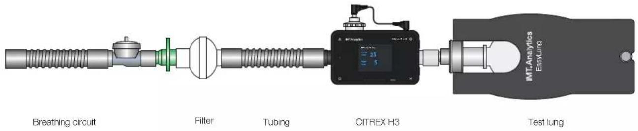
8.2 Measurement setup for checking ventilators
CITREX H3 is ideal for checking ventilators. The best measurement results are achieved with the measurement setup shown below. Make sure the test lung is connected to the grey aluminium connection port of CITREX H3.
flowchart
graph LR
    A["Breathing circuit"] --> B["Filter"]
    B --> C["Tubing"]
    C --> D["CITREX H3"]
    D --> E["Test lung"]
    D --> F["IMT.Analytics EasyLung"]
Figure 24: Measurement setup for checking ventilators
9 Configuration tool
The configuration tool can only be used with Microsoft Internet Explorer.
9.1 PC minimum requirements
Microsoft® Silverlight 5 or higher
Windows x86 or x64 (64-bit mode only supports IE) 1.6 GHz or higher with 512 MB RAM
Macintosh (Intel based) Intel Core Duo 1.83 GHz or higher with 512 MB RAM
Microsoft® Windows® 10, 8.1, 8, Windows Server 2012, 7, 7 SP1, Windows Server 2008 SP2, Windows Server 2008 R2 SP1, Vista
Macintosh OS 10.6 (Intel based), MacOS 10.7 - 10.11 (Intel based)
Ethernet network connection
Screen resolution 1024 × 768 (1280 × 1024 recommended)
9.2 Web server
The Ethernet port on CITREX H3 enables access to the device via a network. Settings can be made on the device via the web browser using the so-called configuration tool. The oxygen option can also be enabled with the web server. The prerequisite for using the web server is an installed Internet Explorer with Microsoft Silverlight 5.
There are three different setting options to establish a connection between CITREX H3 and a computer. Tap the × button until the "Ethernet" menu item appears. You will find a description of the settings in the following sections.
9.2.1 Default
These are default settings that cannot be changed. These settings are recommended in order to establish a direct connection to the computer via an Ethernet cable. The configuration on CITREX H3 is as follows:
IP Address: 192.168.1.1
Subnet Mask: 255.255.255.0
To establish a connection, the network settings on the computer must be changed. For this purpose open the network settings of the computer, which are located in the Control Panel. Then open the "Internet Protocol Version 4 (TCP/IPv4)" settings. Enter an IP address between 192.168.1.2 and 192.168.1.255 and subnet mask 255.255.255.0 in the form on the screen.
Now open Internet Explorer and enter IP address 192.168.1.1 in the address field. The connection to CITREX H3 is established.
9.2.2 Configured
This setting option is suitable for connecting CITREX H3 to a network that does not have a DHCP server. Define an IP address and a subnet mask using the configuration tool on CITREX H3. Then the device can be connected up to the network and be accessed using the defined IP address via Internet Explorer.
9.2.3 DHCP
To connect CITREX H3 to a DHCP server, first connect CITREX H3 to the network. In the "Ethernet" menu select the setting "DHCP". With the IP address shown on the display it is possible to establish a connection to CITREX H3 via Internet Explorer.
9.2.4 Enable oxygen option
With the PC, establish a connection to CITREX H3, as described above. The enable code obtained can be entered in the "Software Options" menu. The code is device-dependent and only has to be entered once.

Figure 25: Enable oxygen option
10 Servicing and care
Careful servicing in compliance with the instructions is essential for ensuring that CITREX H3 operates safely and efficiently. Only components recommended by the manufacturer may be used.

It is absolutely essential to comply with the guidelines and servicing instructions issued by the various manufacturers.

The servicing operations listed below may only be performed by persons who are familiar with CITREX H3. All further repair work may only be performed by authorised trained professionals. Please also observe the information issued by the various manufacturers.
10.1 Preventive cleaning and servicing operations
To ensure that your device operates with precision and reliability for as long as possible, it is essential to perform the following servicing routines regularly.
10.1.1 During operation
Use of the filter included in order to protect the device against contamination. Make sure the device is only used inside a building.
10.1.2 Every 4 weeks
Check the bacterial filter for soiling. For this purpose the pressure drop above the filter must be measured. The pressure drop must not exceed a value of 2 mbar at a flow of 60 L/min. Otherwise the filter must be replaced.
10.1.3 Every 12 months
Factory calibration and servicing to ensure reliable measurement; it may only be performed by IMT Analytics or an authorised partner.
To have CITREX H3 calibrated at the manufacturer's, IMT Analytics, visit the website www.imtanalytics.com/easycal
The EasyCal service makes it possible for users to have CITREX H3 calibrated and adjusted quickly and easily. The annual servicing procedure is also performed.
11 Accessories and spare parts
On the website www.imtanalytics.com you will find the original spare parts and other products from IMT Analytics.
Ordering address:
IMT Analytics AG
Gewerbestrasse 8
CH-9470 Buchs, Switzerland
Tel: +41 (0) 81 750 67 10
Email: sales @imtanalytics.com
Orders can also be placed in our Webstore.
11.1 Accessories table
Options
| 305.056.000 Oxygen sensor with activation code |
| 305.055.000 Warranty extension (plus 2 years) CITREX H3 |
Service
| 000.000.017 Calibration & Servicing CITREX H3 |
| 000.000.022 ISO17025 Calibration & Servicing CITREX H3 |
| 000.000.018 Receiving inspection of CITREX H3 |
| 305.054.000 Triple Calibration & Servicing Package for CITREX H3 |
Accessories & Consumables
| 300.548.000 Adapter set |
| 301.997.000 Car adapter for CITREX |
| 302.077.000 Laminar inlet pipe |
| 304.161.000 Black protective pouch for CITREX |
| 304.161.001 Red protective pouch for CITREX |
| 304.161.002 Blue protective pouch for CITREX |
| 301.851.000 MicroSD memory card |
| 301.655.000 Blind plug for oxygen connector (rubber) |
| 302.178.000 Blind plug for oxygen connector (solid) |
| 301.624.000 Oxygen sensor with mono jack |
| 302.531.000 Bacterial filter RT019 |
| 304.714.000 CITREX stand |
Spare parts
| 301.936.000 Carrying case for CITREX H4 |
| 301.625.000 Battery for CITREX |
| 301.563.000 Network cable |
| 301.673.000 USB cable for CITREX |
| 301.653.000 Oxygen sensor cable |
| 304.578.000 Power supply plug for CITREX |
| 302.780.000 Flow channel protective cap |
Table 7: Accessories
12 Disposal
Disposal of the device is the operator's responsibility. The device can ...
- be delivered, carriage free and duty paid, to the manufacturer for disposal.
- be handed over to a licensed private or public collection company.
- be professionally broken down into its constituent parts by the operator and be recycled or disposed of in accordance with regulations.
In the case of self-disposal the disposal regulations are country-specific and are contained in relevant laws and ordinances. These codes of conduct must be obtained from the authorities responsible.
In this context, wastes must be recycled or destroyed ...
• without endangering human health.
- without using processes or methods that harm the environment, especially water, air, soil, animals and plants.
- without causing noise or odour nuisances.
- without having a detrimental effect on the surroundings or landscape.
13 Directives and approvals
• CE
• CAN/CSA-C22.2 No. 61010-1-12
• UL Std. No. 61010-1 (3rd Edition)
• IEC 61010-1 2010
• IEC 61326-1 2012
• ETSI EN 301 489-17 V3.1.0
• FCC Part 15, Subpart B, Digital Devices, Emission Class B
CE Declaration of Conformity
2014/35/EU (LVD)
DIRECTIVE 2014/35/EU OF THE EUROPEAN PARLIAMENT AND OF THE COUNCIL of 26 February 2014 on the harmonisation of the laws of the Member States relating to the making available on the market of electrical equipment designed for use within certain voltage limits tested according to EN61010-1:2010
2014/30/EU (EMC)
DIRECTIVE 2014/30/EU OF THE EUROPEAN PARLIAMENT AND OF THE COUNCIL of 26 February 2014 on the harmonisation of the laws of the Member States relating to electromagnetic compatibility tested according to EN61326-1:2013
14 Specifications
14.1 Measurement parameter
Flow and pressure measurement Measuring range Accuracy
| Air and N_2 | ||
| Flow measurement ±300 sL/min***±2%* or ±0.1 sL/min** | ||
| Temperature compensated Yes | ||
| Ambient pressure compensated Yes | ||
| Channel pressure compensated | Yes | -50 -600 mbar |
O_2/air mixtures
| Flow measurement ±300 sL/min *** ±2%* or ±0.1 sL/min ** | ||
| Temperature compensated Yes | ||
| Ambient pressure compensated Yes | ||
| Channel pressure compensated | Yes | -50 - 600 mbar |
N_2O/O_2 mixtures
| Flow measurement ±80 sL/min***±4%* or ±0.3 sL/min** | ||
| Temperature compensated Yes 25-30°C | ||
| Ambient pressure compensated Yes | ||
| Channel pressure compensated | Yes | -50 -600 mbar |
Pressure
| In flow channel -50-150 mbar ± 0.75%* or ± 0.1 mbar** | ||
| Barometer 500-1150 mbar ± | 1%* or ± 5 mbar** | |
| Additional readings Measuring range Accuracy | ||
| Oxygen concentration (pressure compensated ≤ 150 mbar) | 0–100% ± 1% O | 2** |
| Gas temperature**** | 0–50°C | ± 1.75%* or ± 0.5°C** |
| Gas type | Air, O_2 , Air/ O_2 , N_2O/O_2 | |
| Gas Standard ATP, ATPD, ATPS, | AP21, STP,STPH, BTPS, BTPS-A, BTPD | |
Table 8: Measurement parameters
Units of measurement
| Flow L/min, L/s, cfm | ||
| Pressure bar, mbar, cmH | _2O , mmHg,inH _2 O |
Table 9: Additional readings
It is the larger tolerance that applies: * Tolerance in relation to the reading ** Absolute tolerance
*** In this User Manual the unit sL/min is based on ambient conditions of 0°C and 1013.25 mbar (DIN1343)
*** CITREX H3 measures the gas temperature inside the measurement channel. While CITREX H3 is warming up, the temperature of the measurement channel, and hence also the temperature of the gas inside the measurement channel, rises at the same time. The measurement channel volume is relatively small, even for relatively high volumetric flows (e.g. PIF @ 60 L/min). If the temperature of the gas on entering CITREX H3 is compared with gas temperature in the measurement channel, it becomes evident that the temperature in the measurement channel is higher. Therefore the temperature of the gas entering the CITREX H3 measurement channel should not be expected to equal the temperature displayed on the screen because the temperature displayed is measured inside the CITREX H3 measurement channel.
| Ventilation parameters Measuring | range | Accuracy | |
| Rate Breaths/min | 1-1000breaths/ | min | ±1 breath or ±2.5%** |
| Time T | i | 0.05-60s±0.02s | |
| Ratio | I:E | 1:300-300:1 | ±2.5%* |
| Tidal volume | V_i | ±10sL | ±2%* or ±0.20mL (>6sL/min)** |
| Minute volume | V_i | 0-300sL/min | ±2.5%* |
| Peak flow | Insp./exp. | ±300sL/min | ±2%* or ±0.1sL/min** |
| Pressure | P_peak , P_mean , PEEP | 0-150mbar | ±0.75%* or ±0.1mbar** |
| Trigger | Adult, Pediatric, Flow, Pres-sure | ||
Table 10: Ventilation parameters
General information
| Screen 1.7" colour display | |
| Interfaces Ethernet | |
| AC input 100–240 VAC (50/60Hz) | |
| Battery operation 4 hours | |
| Dimensions (W × D × H) 11.4 × 7 × 6 cm | |
| Weight 0.38 kg | |
| Calibration interval Once a year | |
| Memory card Yes | |
Operating data
| Ambient temperature 15-40°C (59-104°F) | |
| Air humidity 10-90% RH | |
| Ambient pressure 783-1150mbar | |
| Storage and transport conditions | -10-60°C (14-140°F) at 5-95% RH |
| Degree of soiling | Degree of soiling 2, to IEC 61010-1 |
Table 11: General information and operating data
It is the larger tolerance that applies: * Tolerance in relation to the reading ** Absolute tolerance
*** In this User Manual the unit sL/min is based on ambient conditions of 0°C and 1013.25 mbar (DIN1343).
14.2 Gas type
The gas type measured must agree with the setting on CITREX H3. Please select the correct gas type in the settings.
The following gas types are available for selection:
- Air 100%
- Air/O 2 -Man. Air/oxygen mixture according to manual input; the default is 100% O 2
- Air/O _2 -Auto. (optional) Air/oxygen mixture according to sensor measurement of internal oxygen cell
- N2 O / O2 -Man. Nitrous oxide / oxygen mixture according to manual input; the default is 100 % O2
Standard conditions are understood to mean defined conditions for pressure, temperature and, in some cases, humidity, which constitute the basis for converting the flow actually measured. Therefore it is essential to check which standard condition the value displayed will relate to.
The standard currently set is indicated on the numerical display.

A gas type that has not been selected properly and a gas standard that has not been selected properly can lead to measuring errors of up to 20%.
14.3 Power supply
Input voltage of the power supply unit 100 – 240 VAC, 50 – 60 Hz Supply voltage 5 VDC Power input 2.5–6 W
14.4 Battery operation
Operating time in battery operation 4 hours*
Charging the battery A complete charging process takes 5 to 8 h, depending on which connection port is used for charging. The service life of the battery is extended if the battery is charged completely only after a prompt by the device.
15 Appendix
15.1 Principle of flow measurement
Flow in the flow channel is determined by differential pressure measurement. To build up differential pressure a linear flow element is used to provide flow resistance.

η: dynamic viscosity of the gas [Pa s]
ρ: gas density [kg/m³]
c_1, c_2 : device-specific constants (channel geometry)
Dynamic viscosity
- The viscosity of the medium is its resistance to flow and shear.
• Viscosity is extremely dependent on temperature. - The viscosity of a medium is slightly dependent on the pressure and moisture content of the medium.
Density
• Density is the unit for the mass per unit volume of the medium.
• Viscosity is extremely dependent on temperature.
- The viscosity of a medium is slightly dependent on the pressure and moisture content of the medium.
15.2 Trigger
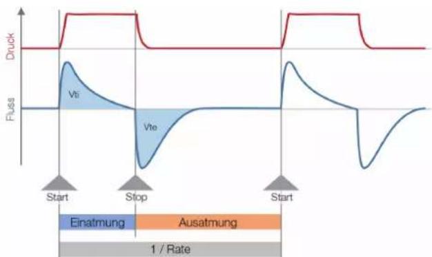
Triggers are used to define start and end points of cyclical signals. With regard to pressure and flow curves the trigger makes it possible to determine inhalation and exhalation. The resulting information constitutes the basis for ventilation parameter calculation. If the trigger is not set properly or if it is not possible to detect a trigger, the ventilation parameters will be calculated incorrectly or not at all.
line
| Phase | Druck | Fluss | | --------- | ----- | ----- | | Start | 0 | 0 | | Stop | 0 | 0 | | Start | 0 | 0 |Figure 26: Trigger
15.2.1 Flow trigger
On CITREX H3 a flow trigger can be set. When the set flow is reached, the trigger is activated. In this context it is essential to specify whether at the start and end of a cycle the trigger is to be activated by a rising edge or a falling edge. Flow measurement in the flow channel serves as the trigger source. CITREX H3 can be operated bidirectionally.
15.2.2 Pressure trigger
In the case of a pressure trigger it is the pressure measured in the flow channel that serves to activate measurement. Whereby the direction of flow is of no consequence.
15.2.3 Base flow
Base flow is a constant flow that must not be included in volume calculation. If, for example, a system has a defined leak, resulting in a constant discharge of 3 L/min, those 3 L/min are not included in the inspiratory volume. The 3 L/min can be entered as a trigger setting so they will not be taken into account.
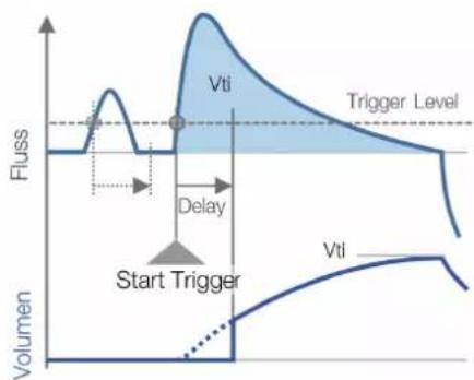
15.2.4 Delay
With a delay it is possible to filter out signal errors or noise and prevent false triggering. As a result, a trigger is only activated if the set trigger level continues to apply after the delay time. If the trigger level is no longer reached after the delay time, no trigger is activated. The delay time can be set.
line
| Vti | Vflss | | ------ | ----- | | Vti | 0.5 |Figure 27: Delay
15.3 Measurement parameters and units
| Pressure readings Measurement parameter Designation Units of measurement | |||
| Ambient pressurePressure in flow channel high | P_atm . P_chane | mbar, bar, in H_2O , cm H_2O , mmHg | |
| Flow readings Measurement parameter Designation Units of measurement | |||
| Flow Flow L/min, cfm, L/s | |||
| Meteorological readings Measurement parameter Designation Units of measurement | |||
| TemperatureOxygen content (option)Volume | Temp. O_2 Volume | °C, K, °F%mL, L, cf | |
| Gas concentrations Measurement parameter Designation Units of measurement | |||
| Gas concentration Gas concentration % | |||
| Ventilation parameters Measurement parameter Designation Units of measurement | |||
| Positive end-expiratory pressureMean pressureMaximum pressure | PEEPPmean P_peak | mbar, bar, in H_2O ,cm H_2O , mmHg. | |
| Inspiratory minute volumeInspiratory/expiratory peak flow | V_i PF _inep/PF_exp | L/min, cfm, L/s, | |
| Inspiratory volumeVentilation rateInspiratory/expiratory ratioInspiratory time | VtiRateI:ETi | mL, L, cfBreaths/mins | |
Table 12: Measurement parameters and units
15.4 Gas standards for flow and volume readings
CITREX H3 converts the flow and volume readings measured in the device to match the conditions of the standard selected. The following gas standards are supported by CITREX H3.
| Gas Standard | Abbreviation | Pressure Temperature | Relative humidity | |
| Ambient Temperature and Pressure ATP Current | ambient pressure | Current gas temperature | Current gas humidity | |
| Ambient Temperature and Pressure Dry ATPD | Current ambient pressure | Current gas temperature | 0% | |
| Ambient Temperature and Pressure Saturated | ATPS Current ambient pressure | Current gas temperature | 100% | |
| Ambient Pressure at 21°C AP21 Current ambient pressure | pressure 21.0°C(70°F) | Current gas humidity | ||
| Standard Conditions USA | STP | 1013.25 mbar (760 mmHg) | 21.0°C (70°F) | 0% |
| Standard Conditions USA Humid | STPH | 1013.25 mbar (760 mmHg) | 21.0°C (70°F) | Current gas humidity |
| Body Temperature and Pressure, Saturated | BTPS | Current ambient pressure + channel pressure | 37.0°C(99°F) | 100% |
| Body Temperature and (Ambient) Pressure Saturated according to ISO 80601-2-12:2011 | BTPS-A | Current ambient pressure | 37.0°C (99°F) | 100% |
| Body Temperature and Pressure Dry | BTPD | Current ambient pressure + channel pressure | 37.0°C(99°F) | 0% |
Table 13: Gas standards for flow and volume readings
15.5 Conversion factors
| Value Equivalent | |||
| 1 mbar 0.001 bar | |||
| 100 Pa | |||
| 1 hPa | |||
| 0.1 kPa | |||
| 0.75006 torr (760 torr = 1 atm.) | |||
| 0.75006 mmHg (at 0°C) | |||
| 0.02953 inHg (at 0°C) | |||
| 1.01974 cmH _2O (at 4°C) | |||
| 0.40147 inH _2O (at 4°C) | |||
| 0.01450 psi, psia | |||
| 1 bar 1000 mbar | |||
| 0.1 Pa | |||
| 1000 hPa | |||
| 100 kPa | |||
| 750.06 torr (760 torr = 1 atm.) | |||
| 750.06 mmHg (at 0°C) | |||
| 29.53 inHg (at 0°C) | |||
| 1019.74 cmH _2O (at 4°C) | |||
| 401.47 inH _2O (at 4°C) | |||
| 14.50 psi, psia | |||
Table 14: Conversion factors
15.6 List of tables
Table 1: Symbol explanation 8
Table 2: Scope of delivery 9
Table 3: Description of electrical interfaces 14
Table 4: User controls 17
Table 5: Trigger settings 19
Table 6: Numerical values 21
Table 7: Accessories 30
Table 8: Measurement parameters 33
Table 9: Additional readings 34
Table 10: Ventilation parameters 34
Table 11: General information and operating data 35
Table 12: Measurement parameters and units 39
Table 13: Gas standards for flow and volume readings 40
Table 14: Conversion factors 41
15.7 List of figures
Figure 1: Power supply 10
Figure 2: Flow channel 11
Figure 3: Oxygen sensor holder 12
Figure 4: Protective cap 12
Figure 5: Screwing in the oxygen sensor 13
Figure 6: Oxygen sensor cable 13
Figure 7: Electrical interfaces 14
Figure 8: Change battery 15
Figure 9: User controls 17
Figure 10: Info display 18
Figure 11: Battery indicator 18
Figure 12: Ethernet interface 18
Figure 13: Trigger 19
Figure 14: Gas standard 19
Figure 15: Gas type 20
Figure 16: Gas humidity 20
Figure 17: O_2 calibration 20
Figure 18: Numerical readings 21
Figure 19: Zero calibration 23
Figure 20: Screen displays "Calibration Air" 24
Figure 21: Screen displays "Calibration Oxygen and Air" 24
Figure 22: General measurement setup 25
Figure 23: Bad setup 25
Figure 24: Measurement setup for checking ventilators 26
Figure 25: Enable oxygen option 28
Figure 26: Trigger 37
Figure 27: Delay 38
15.8 Index
A
Accessories 30
Approvals 32
B
Battery depletion 10
Battery operation 36
C
Calibration 23
Calibration with air 24
Calibration with oxygen and air 24
Care 29
Change battery 15
Change units 22
Charging the battery 36
Cleaning 29
Configured 28
Connecting the device 25
Conversion factors 41
D
Default 27
DHCP 28
Dim screen 16
Directives 32
Disposal 31
Dynamic viscosity 37
E
Electrical interfaces 14
Ethernet 14
F
Filter 21
Flow and volume readings 40
Flow channel 11
Flow measurement 37
G
Gas concentrations 39
Gas Standard 21
Gas standards 40
|
Intended use 6
M
Measurement parameters 33, 39
Measurements 6
Measurement setup 25
Mechanical connectors 11
Meteorological readings 39
MicroSD 14
N
Notes 7
Numerical readings 21
0
O _2 23
O_2 interface 14
Operating time 36
Operation 16
Options 30
Oxygen 23
Oxygen option
Enable oxygen option 28
Oxygen sensor 12
Oxygen sensor, installing 12
P
Parameter 22
PC minimum requirements 27
Personnel 7
Power supply 10, 36
Pressure readings 39
S
Safety instructions 7
Screen lock 16
Service life 7
Servicing 29
Servicing operations 29
Settings 18
Spare parts 30
Specifications 33
Start-up 9
Switching the device on/off 16
Symbol explanation 8
T
Trigger 37
Trigger signal 21
U
Units 39
USB port 14
User controls 17
V
Ventilation parameters 6
W
Web server 27
Z
Zero point 23
IMT Analytics
IMT Analytics
- Table of Contents
- Configuration tool 27
- Servicing and care 29
- Introduction
- Intended use
- Safety instructions
- Representation of hazards, cautions and notes
- Personnel
- Responsibility and guarantee
- Service life
- Symbol explanation
- Start-up
- Power supply
- Mechanical connectors
- Flow channel
- Oxygen sensor (option)
- Installing the oxygen sensor
- Electrical interfaces
- Change CITREX battery
- Operation
- Switching the device on/off
- Screen lock
- Dim screen
- User controls
- Settings
- Info display
- Battery indicator
- Ethernet interface
- Trigger
- Gas standard
- Gas type
- Gas humidity
- Oxygen calibration (optional)
- Numerical readings
- Filter
- The following filters are available:
- Change parameters and units
- Calibration
- Zero point
- Zero Offset
- Oxygen (O _2 ) calibration
- Calibration with air
- Calibration with oxygen and air
- Connecting the device
- General measurement setup
- Configuration tool
- PC minimum requirements
- Web server
- Default
- Configured
- DHCP
- Enable oxygen option
- Servicing and care
- Preventive cleaning and servicing operations
- During operation
- Every 4 weeks
- Every 12 months
- Accessories and spare parts
- Ordering address:
- Accessories table
- Disposal
- Directives and approvals
- CE Declaration of Conformity
- 2014/35/EU (LVD)
- 2014/30/EU (EMC)
- Specifications
- Measurement parameter
- Gas type
- Power supply
- Battery operation
- Appendix
- Principle of flow measurement
- Dynamic viscosity
- Density
- Trigger
- Flow trigger
- Pressure trigger
- Base flow
- Delay
- Gas standards for flow and volume readings
- Conversion factors
- List of tables
- List of figures
- Index
- A
- B
- C
- D
- E
- F
- G
- |
- M
- N
- 0
- P
- S
- T
- U
- V
- W
- Z
- IMT Analytics
Brand : Rigel Medical
Model : Citrex H3
Category : Measuring device