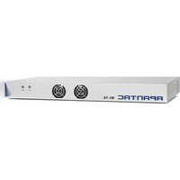
Mi-16 - Network Equipment Apantac - Free user manual and instructions
Find the device manual for free Mi-16 Apantac in PDF.


| Product Type | Multiviewer |
| Brand | Apantac |
| Model | Mi-16 |
| Video Inputs | 16 x 3G/HD/SD-SDI (auto-detect) |
| Video Outputs | 2 identical DVI/HDMI and SDI outputs |
| Loop Outputs | 16 passive SDI loop through |
| Audio Outputs | AES and analog audio monitor outputs |
| Output Resolution | 1920x1080p 50/60Hz |
| Maximum Windows | 16 |
| Power Consumption | 50W |
| Power Supply | 90-250V AC, 50/60 Hz |
| Dimensions (H x W x D) | 1 RU x 19 in x 25 cm (10 in) |
| Rack Mountable | Yes (rack ears included) |
| Warranty | 3 years |
| Input Equalization | 120 m at 2.97 Gbps, 140 m at 1.48 Gbps, 400 m at 270 Mbps (Belden 1694A) |
| Serial Port | RJ45, up to 115200 baud, TSL/TSI/AXP formats |
| IP Control | 100 Base-Tx, TSL/AXP, RJ45 connector |
| General Purpose I/O | Up to 32 inputs via RJ50 to DB9 adapters |
| Embedded Audio | SMPTE-272M-A, up to 16 channels per input, total 128 meters |
| Alarms | No audio, audio high/low, no video, video black, video frozen, WSS, AFD |
| On-Screen Display | Borders, labels, tally UMD, OMD, IMD, dynamic UMD |
| Safety Compliance | FCC Part 15 Class A, CE, EU EMC, C-tick |
| Box Contents | Mi-16 unit, 2 rack ears, 4 RJ50-DB9 adapter cables, 4 DB9 breakout terminal blocks, 1 RJ45-DB9 RS232 cable, 16 terminators, 1 analog audio breakout cable, power cord (North America only) |
Frequently Asked Questions - Mi-16 Apantac
User questions about Mi-16 Apantac
0 question about this device. Answer the ones you know or ask your own.
Ask a new question about this device
Download the instructions for your Network Equipment in PDF format for free! Find your manual Mi-16 - Apantac and take your electronic device back in hand. On this page are published all the documents necessary for the use of your device. Mi-16 by Apantac.
USER MANUAL Mi-16 Apantac
1.0 What's In The Box .... 3
2.0 Key Features....4
2.1 Specifications....5
2.2 Rear Views....6
3.0 Hardware boot up....7
4.0 Software 7
4.1 Changing the Mi-16 IP Address 12
4.2 Configuring of the Mi-16 series.... 13
Mi-16 13
Mi-16+ 14
Mi-16# 15
5.0 Common features and configurations.... 16
5.1 Editing mode.... 16
5.2 System level settings.... 17
5.2.1 Set output timing 17
5.2.2 Sources, Names, Tally and Other Setups 17
5.2.3 Set Tally colors.... 23
5.2.4 System Settings.... 23
5.2.5 Audio reference settings 24
5.2.6 Load presets 24
6.0 Editing 25
6.1 To delete a window 25
6.2 Mi-16 series window styles.... 28
6.3 How to insert a window 30
6.4 Customizing Window Elements.... 30
7.0 Saving Default Layout 45
8.0 Offline Mode.... 46
Appendix.... 47
Mi-16 presets....47
Mi-16+ presets 52
Mi-16# presets 54
Cable Pinouts....57
COPYRIGHT and TRADEMARK.... 58
WARRANTY STATEMENT 58
1.0 What's In The Box
| QTY | Product | Description |
| 1 |  | Mi-16/Mi-16+/Mi-16# multiviewer |
| 2 |  | Rack Ears |
| 4 | 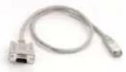 | RJ50 to DB9 adapter cable for GPI |
| 4 |  | DB9 Breakout Terminal Block |
| 1 | 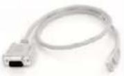 | RJ45 to DB9 adapter cable for RS232 interface |
| 16 |  | Terminators for passive loop outs |
| 1 |  | Analog audio breakout cable |
| 1 | 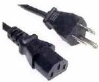 | North American Power Cord. Note: Countries outside of North America the power cord excluded |
| 1 |  | Optional Redundant Power Supply. |
2.0 Key Features
There are 3 models in the Mi-16 family
- Mi-16 - 16x1 multiivewer, one source per window, no copy or duplicating sources
- Mi-16+ - 8x2 multiviewer, one source per window, no copy or duplicating sources
- Mi-16# - 16x2 multiviewer, sources can be copy and duplicated from any input to any output
General features for all Mi-16 series
– Low latency – single frame processing delay
- Accepts 16 auto-detect 3G/HD/SD-SDI inputs
- 16 passive input loop through
- Windows can be sized and moved freely
- Decode up to 16 embedded audio channels per SDI input, up to a total of 128 meters
– Ethernet for configuration and extenernal control
– Dynamic UMD/labes & Tallies (TSL)
- 20 standalone labels
- 4 customizable logos
- 32 GPIs for tallies, count up/down triggers or alarms
Digital and Analog clocks can be sync'd with LTC or NTP
– Borders can be turn on or off
- Safe area markers
– Visual alarm tags for video/audio alarm detection
– Audio monitoring output – stereo, AES, embedded SDI and HDMI
- Optional redundant power supply
- 3 year warranty
Mi-16 specific features
– 2 simultaneous and indentical HDMI and SDI outputs
– Each source can only be assigned to a window once
Mi-16+ specific features
- 2 independent outputs, 8 windows on each output
- 2 analog and 2 digital clocks
– Each source can only be assigned to a single window
Mi-16# specific features
- 2 independent outputs
- 2 analog and 2 digital clocks
– Each source can be freely assigned to any window
– Each source can be copied up to 16 times as long as they are the same size
– Each source can be copied to a different size window, but only up to 16 times - Once a source is copied to a different size, the total number of sources will be decrease by one.
2.1 Specifications
| Mi-16 SPECIFICATIONS | |||
| Inputs | 16 3G/HD/SD-SDI | Video Outputs | 2 identical DVI/HDMI, SDI |
| Loop outs | 16 passive loop outs | Audio Outputs | AES and Analog audio monitor outputs |
| Connectors | BNC IEC 61169-8 Annex A | Output Resolution | 1920 x 1080p 50/60Hz |
| Total Windows | 16 | On Screen Display | Borders, labels, tally UMD, OMD, IMD, dynaimic UMD |
| Serial Digital | SMPTE 424M, 292M, 259M | General Purpose IO | Up to 32 inputs with RJ50 - DB9 connectors |
| Equalization | 120m at 2.97 Gbps, 140m at 1.48 Gbps, 400m at 270 Mbps with Belden 1694A | Serial Port | Connector: RJ45, Baud Rate up to 115200 Format, TSL, TSI, AXP |
| Return Loss | >15db up to 1.485 Gbps >10db up to 3G | IP | 100 Base-Tx, TSL, AXP Connector: RJ45 |
| Embedded Audio | SMPTE-272M-A | Electrical | 50W, 90-250V 50/60 Hz |
| Alarms | No audio, audio high/low, no video, video black, video frozen, WSS, AFD | EMI/RFI | Complies with FCC Part 15 Class A, CE, EU EMC, C-tick |
| Power | 90-250 AC / 12 DC | Size | 1 RU, 25 cm (10") |
| Mi-16+ SPECIFICATIONS | |||
| Inputs | 16 3G/HD/SD-SDI | Video Outputs | 2 independent DVI/HDMI, SDI outputs |
| Loop outs | 16 passive loop outs | Audio Outputs | AES and Analog audio monitor outputs |
| Connectors | BNC IEC 61169-8 Annex A | Output Resolution | 1920 x 1080p 50/60Hz |
| Total Windows | 16 | On Screen Display | Borders, labels, tally UMD, OMD, IMD, dynaimic UMD |
| Serial Digital | SMPTE 424M, 292M, 259M | General Purpose IO | Up to 32 inputs with RJ50 - DB9 connectors |
| Equalization | 120m at 2.97 Gbps, 140m at 1.48 Gbps, 400m at 270 Mbps with Belden 1694A | Serial Port | Connector: RJ45, Baud Rate up to 115200 Format, TSL, TSI, AXP |
| Return Loss | > 15db up to 1.485 Gbps > 10db up to 3G | IP | 100 Base-Tx, TSL, AXP Connector: RJ45 |
| Embedded Audio | SMPTE-272M-A | Electrical | 50W, 90-250V 50/60 Hz |
| Alarms | No audio, audio high/low, no video, video black, video frozen, WSS, AFD | EMI/RFI | Complies with FCC Part 15 Class A, CE, EU EMC, C-tick |
| Power | 90-250 AC / 12 DC | Size | 1 RU, 25 cm (10") |
Mi-16# SPECIFICATIONS
| Inputs | 16 3G/HD/SD-SDI | Video Outputs | 2 independent DVI/HDMI, SDI outputs |
| Loop outs | 16 passive loop outs | Audio Outputs | AES and Analog audio monitor outputs |
| Connectors | BNC IEC 61169-8 Annex A | Output Resolution | 1920 x 1080p 50/60Hz |
| Total Windows | 32+ | On Screen Display | Borders, labels, tally UMD, OMD, IMD, dynaimic UMD |
| Serial Digital | SMPTE 424M, 292M, 259M | General Purpose IO | Up to 32 inputs with RJ50 - DB9 connectors |
| Equalization | 120m at 2.97 Gbps, 140m at 1.48 Gbps, 400m at 270 Mbps with Belden 1694A | Serial Port | Connector: RJ45, Baud Rate up to 115200 Format, TSL, TSI, AXP |
| Return Loss | >15db up to 1.485 Gbps >10db up to 3G | IP | 100 Base-Tx, TSL, AXP Connector: RJ45 |
| Embedded Audio | SMPTE-272M-A | Electrical | 50W, 90-250V 50/60 Hz |
| Alarms | No audio, audio high/low, no video, video black, video frozen, WSS, AFD | EMI/RFI | Complies with FCC Part 15 Class A, CE, EU EMC, C-tick |
| Power | 90-250 AC / 12 DC | Size | 1 RU, 25 cm (10") |
2.2 Rear Views

Figure 2-1 Mi-16x rear view
APANTAC LLC, 7470 SW BRIDGEPORT ROAD, PORTLAND, OR 97224
INFO@APANTAC.COM, TEL: +1 503 968 3000, FAX: +1 503 389 7921
3.0 Hardware boot up
There is no on/off on the Mi-16, this is due to the UL safety regulation imposed on 1 rack unit products. To power on the Mi-16, insert power cord directly to the AC power receptacle, the Mi-16 will boot in approximately 10 seconds. When the HDMI output is connect to the screen, the following information will display on the lower third of the display for about 5 seconds (see Fig. 1), then followed by the Apantac logo, then the very last screen layout prior to powering off the unit.

Figure 1: FPGA/FW versions and IP address of the unit will be displayed for 5 seconds
4.0 Software
This section will help you get the Mi-16 setup as quickly as possible.
Before you can successfully run the jDirector, you must first run the installation from the provided CD or download it from the Apantac website.
After completing the Apantac jDirector software installation open the application by using the shortcut created on the Windows Desktop or from the shortcut in the Windows Start Menu under the APANTAC folder.

Apantac
Mi-16
jDirector
When launching the jDirector software you will first see the initialization screen.

Figure 2: jDirector Initialization screen
To connect to the multiviewer your PC must be connected to the same subnet as the multiviewer. The IP address(es) is displayed briefly on the monitor attached to the corresponding output at boot up.
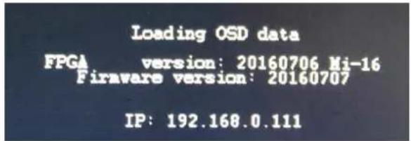
Figure 3: IP address of the unit will be displayed for 5 seconds on boot up. The default IP address is 192.168.0.100
To connect to the Mi-16 multiviewer click the Add / Remove Multiviewer button
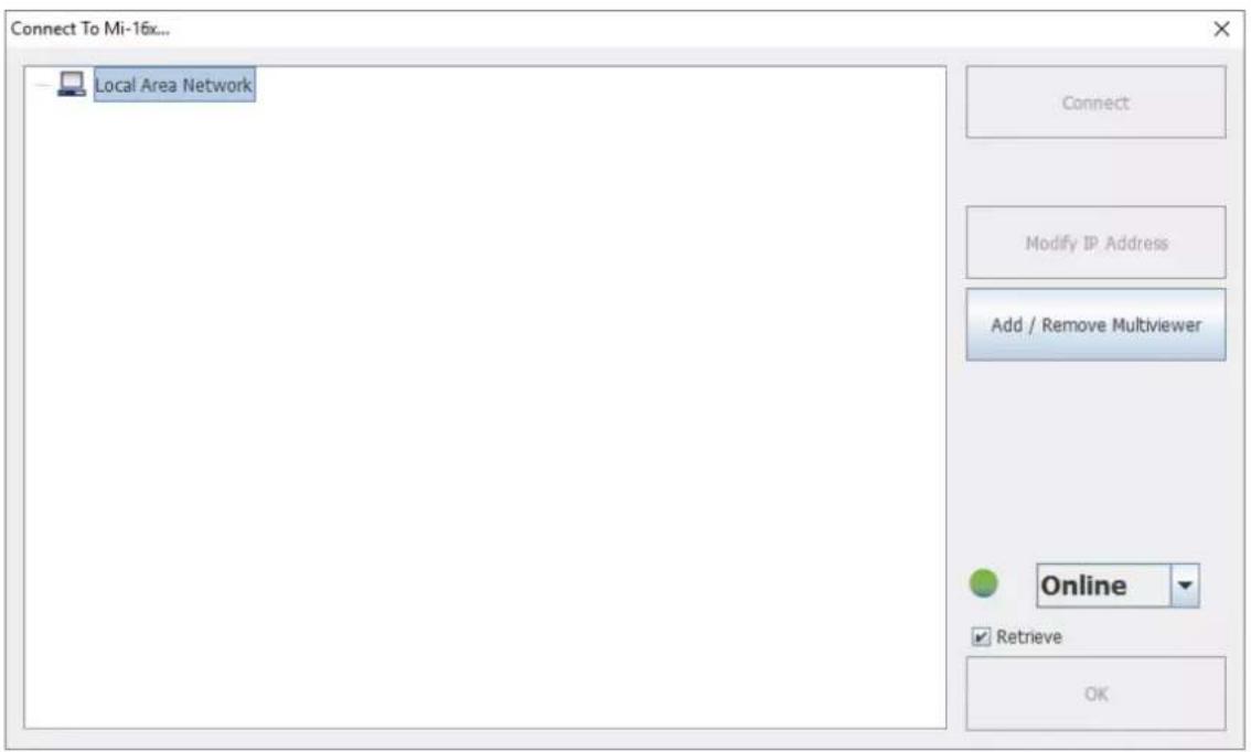
Figure 4: Local Area Network -> Mi-16x IP Address Manager
- Click the ADD Mi-16x button

Figure 5: Add Mi-16 module
There are 3 different models in the Mi-16 series, Mi-16, Mi-16+ and Mi-16#


Figure 6: Select your Mi-16 model and then enter the IP address
Note: Even if you select incorrect Mi-16 model, the jDirector will automatically detect the proper version of hardware you have.
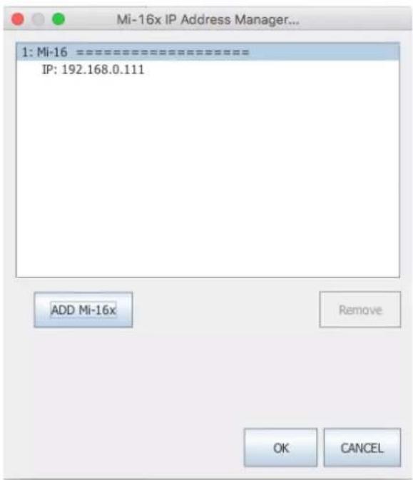
Figure 7: Add Mi-16 module
After you have completed the above steps, click "OK" to continue, then the jDirector will take to the overview mode of the user interface.
If you have already connected to this Mi-16 once before, you may see this dialog when you connect to it again, click on "OK" to continue.

Figure 8: Connecting to a Mi-16 that displays a previous connection
4.1 Changing the Mi-16 IP Address
When at the "Connect to the Mi-16x..." window when first opening the jDirector software you should see the current IP address if you have added a unit with the above instructions or have previously connected to the Mi-16.
- Left click on the Network line to highlight it.
- Click the Modify IP Address button.
- Enter in the desired IP address, Subnet mask and Gateway.
Then confirm the change by clicking the OK button.
■ Reboot the Mi-16 unit to make the change active.

Figure 9: Mi-16 change IP Address.
4.2 Configuring of the Mi-16 series
Mi-16
The Mi-16 is the most basic model of the Mi-16 family. There are 16 inputs and 1 output. Each source can be only assigned to a single window. Once the jDirector is connected to the Mi-16, the following editor layout will appear:
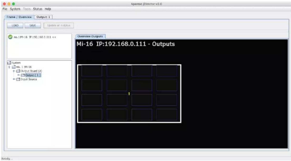
Figure 10: Mi-16 Overview Mode
Select the Output 1 tab at the top or double click within the white outline of theOverview Output and this will take you to jDirector's editing mode.
Mi-16+
The Mi-16+ is the medium model of the Mi-16 family. There are 16 inputs and 2 outputs with 8 windows on each output. Each source can be only assigned to a single window. Once the jDirector is connected to the Mi-16+, the following editor layout will appear:

Figure 11: Mi-16+ Overview Mode
Select the Output 1 or Output 2 tab at the top or double click within the white outline of desired output in the Overview Output and this will take you to jDirector's editing mode.
Mi-16#
The Mi-16# is the most advanced model of the Mi-16 family. There are 16 inputs and 2 outputs, each output can have up to 16 windows. Each source can be copied to multiple windows of the same size or different sizes. Once the jDirector is connected to the Mi-16#, the following editor layout will appear:
Note: In the Mi-16# there are 16 windows resources; when a source is copied to a same size window it will not consume any additional window resources, however when a source is copied to a different size window than its original size it will consume one additional window resource. For example if source one is copied to a different size window then there are only 14 window resources left instead of 15.

Figure 12: Mi-16# Overview Mode
Select the Output 1 or Output 2 tab at the top or double click within the white outline of desired output in the Overview Output and this will take you to jDirector's editing mode.
5.0 Common features and configurations
5.1 Editing mode
The jDirector editor consists of four major work areas:
- Tool Bar – this is where all the tool short cuts reside
- Work Space – this is the space to edit the on screen layout and look
- Window Bin – this is where all the windows templates reside
-
Object Bin – this is where all the objects such as standalone labels, digital clocks, analog clocks and temperature alarm reside
-
button on the tool bar will update the currently active layout on the PC to the Mi-16 output.
![Output 1 Output 2 Tool Bar Work Space Window Bin Object Bin File System Tools Status Help Frame Overview Update 1 Update 2 Update Zoom In Input (1) Input (2) Input (3) Input (4) Input (5) Input (6) Input (7) Input (8) LTC hh:mm:ss Mi-16+ Output 1 Latest LPROS (19) Audio Bin Group (8) - [16] Temperature (2)](/content/2026/05/1062180/images/e9bd8ade542ec5d97f3ee3cafdb097483099ea7c5402ecb3f96030b2c3366451.jpg)
Figure 13: Mi-16 editing mode
Note: Mi-16 will only have Output 1 whereas Mi-16+ and Mi16# will have both Output 1 and Output 2.
5.2 System level settings
5.2.1 Set output timing
The Mi-16 series comes with the default output setting of 1080P 60Hz, it can easily be changed to 1080P 50Hz by doing the following,
On the Top Level Menu, click on System -> Output Manager to set the output timing.

Figure 14: Output Manager
5.2.2 Sources, Names, Tally and Other Setups
Every Mi-16's source attributes can be configured in a single place. Since the Mi-16# allows copying of the sources these attributes can follow the sources every time it is assigned to a new window.
These attributes are as follows:
Names
- The default names are Input (1) to Input (16), each name can have up to 32 characters
- The names can be static or dynamic. When the names are set to dynamic, the UMD of the window will become blank and waiting for the name assignment to come from an external tally management system such as TSL or TSI.
TSL
In order for the names to be dynamic the TSL address is assigned to each source. The default assignment is 0 \~ 16
Tally Mode
The Tally can be either trigger via GPI or an external tally management system such as TSL or TSI.
Tally attributes
Whether the tally trigger is GPI or TSL the tally indicators can be assigned to on screen elements such as LEDs, borders, UMD text and UMD text colors.
To start configuring the Input Source table
On the top menu, go to System -> Input Source Manager, the Input Source Manager dialog will pop up.
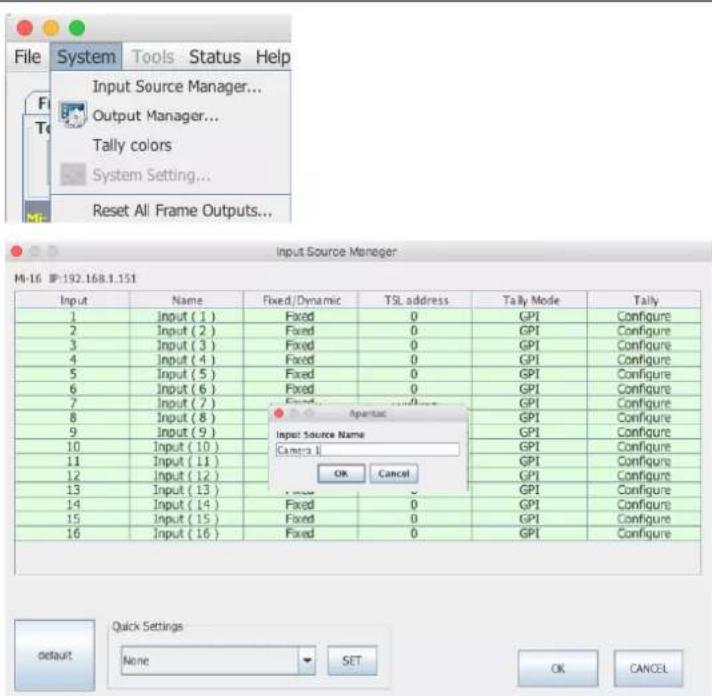
Figure 15: Input source manager
Name the source
Click on any of the Name field and start assigning names. Click

Figure 16: Enter source names
Continue to name all the sources.

Figure 17: Input source manager with updated names
Quick Settings
There are several quick settings that will speed up the setup process

Figure 18: Enter source names
Mi-16 series
| Set all attributes to default | 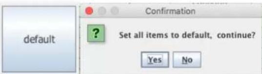 | |
| Figure 19: Enter source names | ||
| Rest Input Names – will set all the input names back to Input (1), Input (2) and so on |  |  |
| Figure 20: Enter source names | Figure 21: Enter source names | |
| Clear all source Tally GPI bit – will clear all GPI tally settings |  |  |
| Figure 22: Enter source names | Figure 23: Enter source names | |
| Tally - 1 GPI bit per source- will sequentially assign one GPI tally per source |  |  |
| Figure 24: Enter source names | ||
| Tally - 2 GPI bit per source- will sequentially assign two GPI tally per source |  |  |
| Figure 25: Enter source names | Figure 26: Enter source names | |
| All Input Names TSLwill change all Fixed/Dyanmic Names from "Fixed" to "Dynamic" |  | 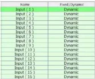 |
| Figure 27: Enter source names | Figure 28: Enter source names | |
| All Input Names staticwill change all Fixed/Dyanmic Names from "Dynamic" to "Fixed" |  | 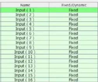 |
| Figure 29: Enter source names | Figure 30: Enter source names | |
| Reset TSL Addresseswill set all TSL address back to default 0 ~ 15 |  | 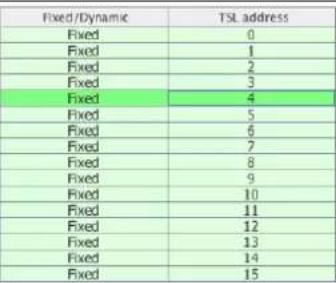 |
| Figure 31: Enter source names | Figure 32: Enter source names | |
| Settings | ||
| Change Name from Fixed to Dynamic and vise versa |  Figure 33: Enter source names Figure 33: Enter source names | |
| Change TSL addressesk. Double Click on the TSL address Cell and change it to the desired number between 0 to 127 |  Figure 34: Enter source names Figure 34: Enter source names | |
| Change the Tally Mode between GPI to Tally | 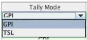 Figure 35: Enter source names Figure 35: Enter source names | |
| Set GPI Tally attributes.Set Tally mode to GPI then double click on Tally -> Configure | 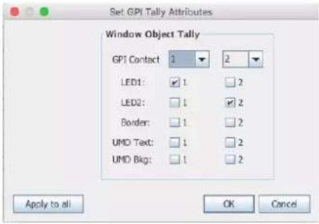 Figure 36: Enter source names Figure 36: Enter source names | |
| Set TSL Tally attributes.Set Tally mode to TSL then double click on Tally -> Configure |  Figure 37: Enter source names Figure 37: Enter source names | |
5.2.3 Set Tally colors
| Set Tally Colors. System -> Set Tally colors | 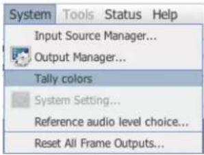 |
5.2.4 System Settings
| Set system settings. System -> System Settings |  |
| RS-232 Communication mode can be set for software control or TSL. Temperature alarm setting as well as current temperature will also be shown in this dialog. |  |
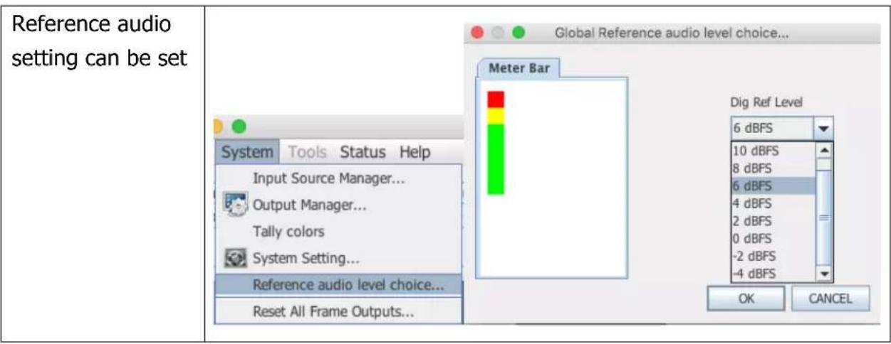
5.2.5 Audio reference settings
5.2.6 Load presets
The Mi-16 series can have up to 30 presets. Each Mi-16x comes with 10 preloaded presets. Please see Appendix A for all the preset layouts.
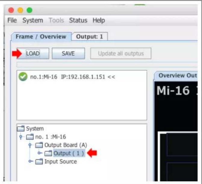
| Load Presets by File -> Glogal -> LOAD | Figure 38: File -> Global -> LOAD |
| Highlight the preset you want to load, then click on |
You can also load preset from the overview mode. Highlight the preset you want to load then clock on
6.0 Editing
6.1 To delete a window
There are two methods to remove a window.
- Highlight the window you would like to delete
a. Press the
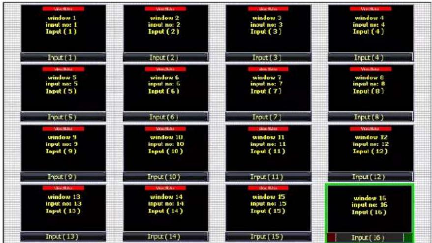
Figure 39: Click on the window you want to delete to highlight it then press the
b. Or right click on the window and select

Figure 40: Right click on the window you want to delete to highlight it then select

Figure 41: The end result
How to delete multiple windows
- Press and hold the
Key - Highlight the windows you would like to delete
a. Press the


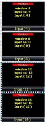
Figure 42: Hold down the CTRL key and click on multiple windows then press the
b. Or right click on one of the highlighted windows and select

Figure 43: Hold down the CTRL key and click on multiple windows then right click on a highlighted window then select

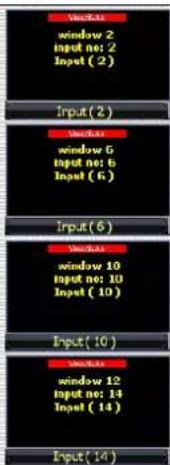

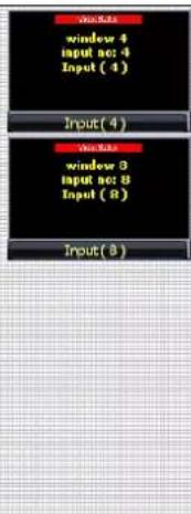
Figure 44: The end result
6.2 Mi-16 series window styles
- The Mi-16 series comes with 5 basic window styles.
These styles are located in the "Window Bin" area of the jDirector editor.
○ Each window style consists of 4 window templates
○ Each window has 5 predefined sizes – 1/4, 1/9, 1/16, 1/25 and 1/36

Figure 45: Click on the window style you want to load.
Style 1 templates – windows with 2 tally LEDs

Figure 46: Click on the window preset you want to load.
Style 2 templates – windows with no tally LEDs
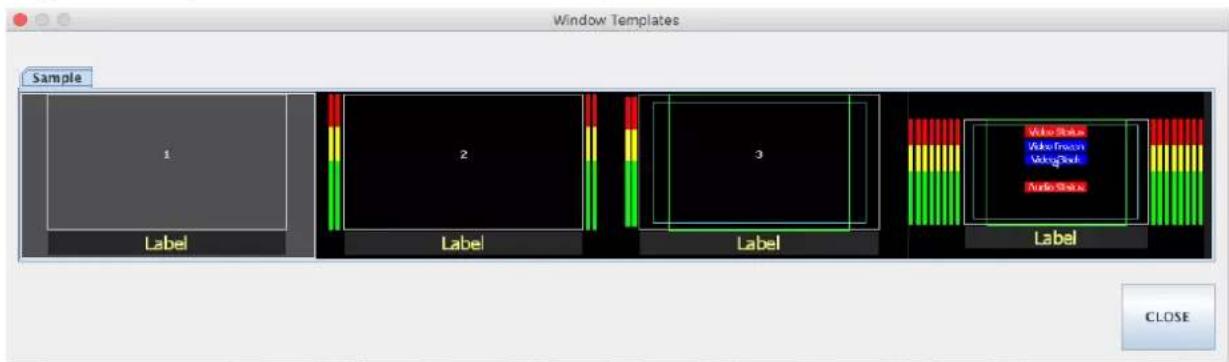
Figure 47: Click on the window preset you want to load.
Style 3 templates – windows with skin labels and 2 tally LEDs

Figure 48: Click on the window preset you want to load.
Style 4 templates – windows with skin labels and no tally LEDs

Figure 49: Click on the window preset you want to load.
Style 5 templates – windows with labels and tally LEDs over the video

Figure 50: Click on the window preset you want to load.
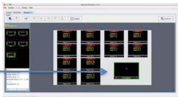
6.3 How to insert a window

- Click on a window style

- Select the template
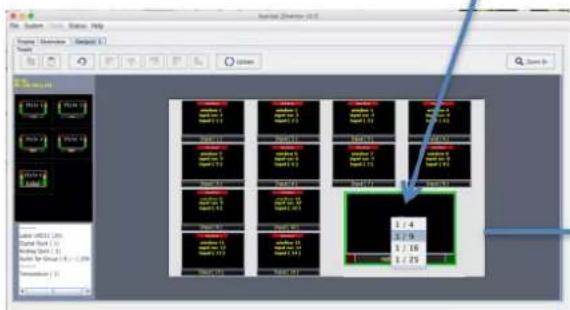
- Select the window size
flowchart
graph TD
    A["Data Input"] --> B["Data Processing"]
    B --> C["Storage Module"]
    C --> D["Data Output"]
    D --> E["Storage Details"]
    style A fill:#f9f,stroke:#333
    style B fill:#ccf,stroke:#333
    style C fill:#cfc,stroke:#333
    style D fill:#fcc,stroke:#333
    style E fill:#ffc,stroke:#333
- Place the window
Figure 51: Steps to place a window onto the layout.
6.4 Customizing Window Elements
In addition to window templates each window elements can still be customized by right clicking on the window.
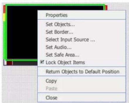
Figure 52: Right click on a window
Set Window Objects
Tally LEDs:
On/off
Borders:
On/off, width and skin
OMD/UMD:
On/off
Alarm tags:
Video format, Video frozen

Figure 53: Select

Figure 54: Check the objects to turn on/off
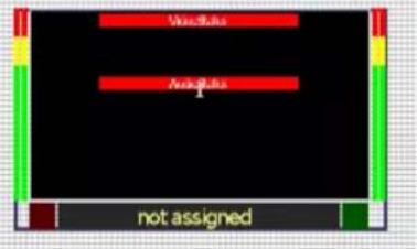
Figure 55: Alarm tags turned on
Set Borders:
■ Size 0 to 7 pixels
■ Size 0 = border off
- Colors

Figure 56: Select

Figure 57: Set Window border

Figure 58: Alarm tags turned

Figure 59: Alarm tags turned on
Set Border Skins:
There are 6 predefined skins. If you would like to make your own skins please contact Apantac tech support for further assistance.

Figure 60: Choose Skin Border

natural_image
Computer monitor blank screen with no visible text, labels, or symbolsFigure 61: Skin 1

natural_image
Solid black rectangle with a yellow border at the bottom (no text or symbols)Figure 62: Skin 2
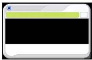
natural_image
Simple icon of a computer monitor with a green progress bar and black screen (no text or symbols)Figure 63: Skin 3

natural_image
Solid black rectangular frame with no visible text, symbols, or markingsFigure 64: Skin 4

Figure 65: Skin 5

natural_image
Pure electrical circuit lines without any symbolsFigure 66: Skin 6
Select Input Source.
Note:
Only the Mi-16# allows you to freely assign sources to a window.
Mi-16 and Mi-16+ the sources are only assignable to a single window. If source is green as seen in Figure 68 the source is available. If it is black the source has been used.

Figure 67: Select Input source
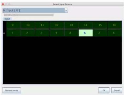
Figure 68: The available sources
Adding / removing audio meters to windows by right clicking on a window and select
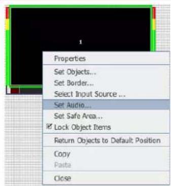
Figure 69: Select Audio
Once a source is assigned to a window, you can now make audio assignments to the meters. You can assign up to 16 channels of audio to a single window

Figure 70: Alarm tags turn

Figure 71: Alarm tags turn
Set Safe Area
Each window can have up to 2 safe areas.
To set and enable the safe area right click on a window and select

Figure 72: Enable first safe area

Figure 73: Enable first safe area
There are two tabs
Safe Area 1 and Safe Area 2
Check the "Enable" box on
Safe Area 1 then use the
Percentage slider to move the
safe area to 5% on each side.

Figure 74: Set percentage
Click on Safe Area 2 tab Check the "Enable" box then select Ratio Fix <4:3> then click OK to exit

Figure 75: Enable second safe area and enable 4x3 safe area
You can now see the safe areas enabled on the window

Figure 76: After safe area was turned on
Unlocking objects The objects in the windows cannot be moved until it is unlocked
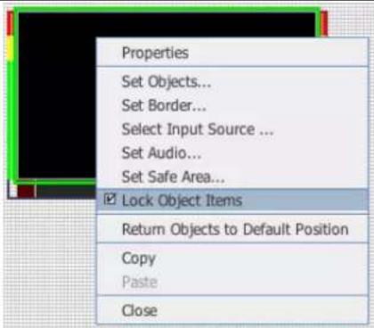
Figure 77: Lock Object Items toggle
Return objects to default position – returns all objects to the position prior to their move

Figure 78: Return Objects to Default Position
Copy/Paste – Windows can be copied and pasted

Figure 79: Copy/Paste of Windows
Setup standalone label
![Apantac jDirector v2.0 File: System Tools Status Help Frame / Overview Output: 1 Tools Update Zoom In Style 1 Style 2 Style 3 Style 4 Style 5 Label Label UMOD3 (19) Digital Clock (1) Analog Clock (1) Audio Bar Group (8) - (256 Temperature (2) late [80, 864, 496, 37]](/content/2026/05/1062180/images/e6e2403878203b2b80f5928a60cc503d1048f84f4c7e13595a6bb3dd4fca3df0.jpg)
Figure 80: Insert Label
Insert Digital Clock.
Drag "Digital Clock" into the work space

Figure 81: Drag the digital clock onto the workspace
Right click on the Clock to bring up the properties dialog.
Option
Uncheck "Enable DATE", "Enable YEAR",
Name
Remove "Clock" from the Name field
Time Zone
Select the time zone from the drop down menu.

Figure 82: Edit digital clock properties

Figure 83: The digital clock
| Clock Font ColorSet Font Color to white,clickClock Background ColorSet Background Color to black then click | 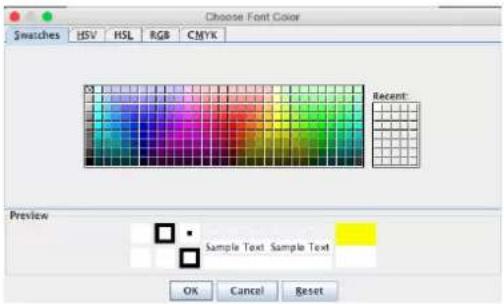 Figure 84: Edit font color Figure 84: Edit font color Figure 85: Edit background color Figure 85: Edit background color | |
| Label PropertiesRight click on the label to bring up the properties dialog.Select Font 4 for the largest size font. |  Figure 86: Set label properties Figure 86: Set label properties |  Figure 87: Set label properties Figure 87: Set label properties |
| Label Font ColorSet font color to White clickLabel Background ColorSet background color to black then click |  Figure 88: Set font color Figure 88: Set font color |  Figure 89: Set background color Figure 89: Set background color |
Figure 88: Set font color
Figure 89: Set background color
Mi-16 series
| Set Label Mode:Follow Source or Static.When set toFollow Sourcethe label namewill follow the nameassigned in theInput Source Manager.When set tothe label name can be manually renamed tonames such as "Program"and "Preview" |  Figure 90:Set Label Mode Figure 90:Set Label Mode |
| To insert a Digital Clockclick and hold then dragtheto the layout Work Space. | 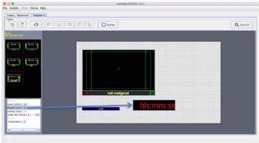 Figure 91:Insert a Digital Clok Figure 91:Insert a Digital Clok |
| Right Click on the digitalclock in the the WorkSpace and then selectProperties from thecontextual menu to openthis configuration dialog. | 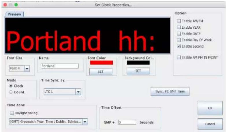 Figure 92:Set Clock Properties Figure 92:Set Clock Properties |
The font size of the clock can be set in 4 different sizes.
The digital clock can be named in the Name box.
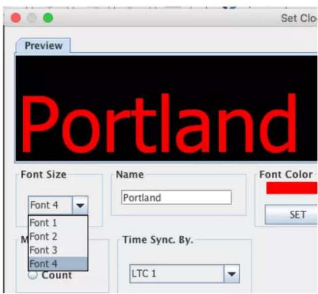
Figure 93: Clock Font Size
The digital clock properties can be set as the following:
- Clock or a counter
- can be sync'd to Internal, LTC or NTP
- Daylight savings on/off
- Time zone selection for the clock when set to Internal
When the clock is set to Internal it can be sync'd to the PC's clock by clicking on

Figure 94: Clock Sync method selection

Figure 95: Sync the Clock with the connected PC
Insert an Analog Clock by dragging the
![Aventra Director v2.0 File System Tools Status Help Tools Update Zoom In Style 1 Style 2 Style 3 Style 4 Style 5 Label Label UNDS2 (36) Digital Clock (2) Audio Clock (1) Audio for Group (8) - [128] Picture LOGO (4) Temperature (2)](/content/2026/05/1062180/images/63d2c3fcb9a817d99050c266fafc97289c16e466130ba346518a7cc0e45e0a72.jpg)
Figure 96: Insert Analog Clock
To set the properties on the analog clock right click on the clock and select

Figure 97: Open Analog Clock Properties
The analog clock properties can be set as the following:
- Can be sync'd to Internal, LTC or NTP
- Daylight savings on/off
- Time zone selection for the clock when set to Internal
When the clock is set to Internal it can be sync'd to the PC's clock by clicking on
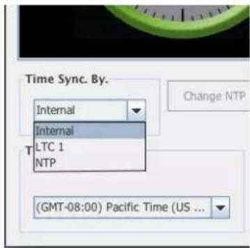
Figure 98: Time Sync method

Figure 99: Time Zone selection

Figure 100: Sync the Clock with the connected PC
Clock faces
There are 3 different clock faces (skins) you can choose from.
The clock hands and color can also be configured

Figure 101: Skin Type 1

Figure 102: Skin Type 2
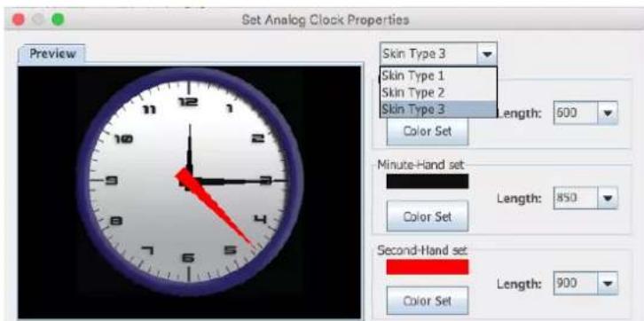
Figure 103: Skin Type 2
To adjust the GMT time right click on the Clock and select

Figure 104: Adjust GMT Time
Add standalone audio meters by dragging the
Right click on the meters to set the properties.

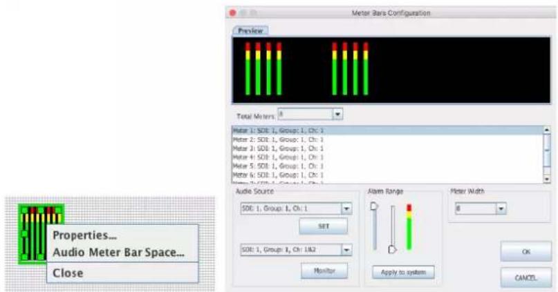
Figure 105: Add standalone Audio Meters
Audio sources can be assigned to each of the meters.
Any pair of the audio meters can also be sent to the audio monitoring output by clicking on
Audio alarm range and audio meter width can also be set here.


Figure 106: Audio Meter configuration
| Add a logo to the layout by dragging the Picture LOGO to the Workspace.When letting go of the mouse button a dialog box will open for you to choose the logo file. |  Figure 107: Adding custom logo to Workspace Figure 107: Adding custom logo to Workspace |
| Insert a temperature warning by draggingto the workspace. |  Figure 108: Adding Temperature Alarm Figure 108: Adding Temperature Alarm |
| Set Temperature alarm property by right clicking on the temperature alarm |  Figure 109: Temperature Alarm configuration Figure 109: Temperature Alarm configuration |
7.0 Saving Default Layout
The Default Layout is the layout loaded by the Multiviewer during the power on sequence. This layout is similar to a Saved Preset file but is treated differently by the Multiviewer, as it will not be visible under the Preset Load dialog. A common practice is to create the desired layout save it as a preset for future use and then performing the Quit and Save function by exting the jDirector software. This Quit and Save is what gerenates the Default Layout or sometimes referred to as the Last Layout or Latest Layout.
After creating your desired layout or Loading a previously saved Preset file it is recommended that you first Update all outputs so all changes are reflected on your Outputs and then select File>Exit.

This will prompt you with the Exit Confirmation dialog box.
Complete the save by selecting the checkbox for Save configurations to flash and then click the Quit and save button.

The Default Layout is updated each time a Quit and Save is completed.
8.0 Offline Mode
The jDirector software can also work in offline mode.
Note: Some features do not behave normally under Offline mode.
| Start with a fresh copy of jDirector and select offline mode |  |
| It will prompt you to copy your online folder to the offline folder. If you would like to continue to make edits to your online layout then click, otherwise click |  |
| Add a Mi-16 to the editor. You can choose from the list. |   |
| Once you enter the offline mode, you can start editing as if you were online. | 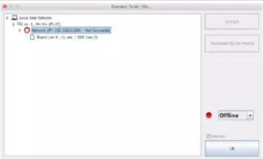 |
Appendix
Mi-16 presets
The Mi-16 can store up to 30 presets. It comes with 10 pre configured layouts as below,

Figure 110: Preset1 – 16 windows (Preset1.OPx)

Figure 111: Preset2 – 16 windows with 2 Tally LEDs (Preset2.OPx)

Figure 112: Preset3 – 16 windows with 2 audio meters each (Preset3.OPx)
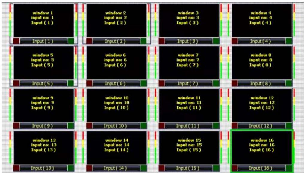
flowchart
graph TD
    subgraph_Input_1["Input (1)"]
        A1["window 1\ninput no: 1\nInput (1)"]
        B1["window 2\ninput no: 2\nInput (2)"]
    end
    subgraph_Input_2["Input (2)"]
        C1["window 3\ninput no: 3\nInput (3)"]
        D1["window 4\ninput no: 4\nInput (4)"]
    end
    subgraph_Input_3["Input (3)"]
        E1["window 5\ninput no: 5\nInput (5)"]
        F1["window 6\ninput no: 6\nInput (6)"]
        G1["window 7\ninput no: 7\nInput (7)"]
        H1["window 8\ninput no: 8\nInput (8)"]
    end
    subgraph_Input_4["Input (4)"]
        I1["window 9\ninput no: 9\nInput (9)"]
        J1["window 10\ninput no: 10\nInput (10)"]
        K1["window 11\ninput no: 11\nInput (11)"]
        L1["window 12\ninput no: 12\nInput (12)"]
    end
    subgraph_Input_5["Input (5)"]
        M1["window 9"]
        N1["window 13"]
        O1["window 14"]
        P1["window 15"]
        Q1["window 16"]
    end
    subgraph_Input_6["Input (6)"]
        R1["window 6"]
        S1["window 7"]
        T1["window 8"]
        U1["window 9"]
        V1["window 10"]
        W1["window 11"]
        X1["window 12"]
        Y1["window 13"]
        Z1["window 14"]
        AA1["window 15"]
        AB1["window 16"]
    end
    subgraph_Input_7["Input (7)"]
        AC1["window 7"]
        AD1["window 8"]
        AE1["window 9"]
        AF1["window 10"]
        AG1["window 11"]
        AH1["window 12"]
        AI1["window 13"]
        AJ1["window 14"]
        AK1["window 15"]
        AL1["window 16"]
    end
    subgraph_Input_8["Input (8)"]
        AM1["window 8"]
        AN1["window 9"]
        AO["window 10"]
        AP["window 11"]
        AQ["window 12"]
        AR["window 13"]
        AS["window 14"]
        AT["window 15"]
        AU["window 16"]
    end
    subgraph_Input_9["Input (9)"]
        AV["window 9"]
        AW["window 10"]
        AX["window 11"]
        AY["window 12"]
        AZ["window 13"]
        BA["window 14"]
        BB["window 15"]
        BC["window 16"]
    end
    subgraph_Input_10["Input (10)"]
        BD["window 9"]
        BE["window 10"]
        BF["window 11"]
        BG["window 12"]
        BH["window 13"]
        BI["window 14"]
        BJ["window 15"]
        BK["window 16"]
    end
    subgraph_Input_11["Input (11)"]
        BL["window 9"]
        BM["window 10"]
        BN["window 11"]
        BO["window 12"]
        BP["window 13"]
        BQ["window 14"]
        BR["window 15"]
        BS["window 16"]
    end
    subgraph_Input_12["Input (12)"]
        BT["window 9"]
        BU["window 10"]
        BV["window 11"]
        BW["window 12"]
        BX["window 13"]
        BY["window 14"]
        BZ["window 15"]
        CA["window 16"]
Figure 113: Preset4 – 16 windows with 2 Tally LEDs and 2 Audio Meters (Preset4.OPx)

Figure 114: Preset5 – 14 windows (Preset5.0Px)

Figure 115: Preset6 – 14 windows with 2 audio meters (Preset6.OPx)
| window 1 input no: 1 Input (1) | window 2 input no: 2 Input (2) | window 3 input no: 3 Input (3) | window 4 input no: 4 Input (4) |
| Input (1) | Input (2) | Input (3) | Input (4) |
| window 5 input no: 5 Input (5) | window 6 input no: 6 Input (6) | window 7 input no: 7 Input (7) | window 8 input no: 8 Input (8) |
| Input (5) | Input (6) | Input (7) | Input (8) |
| window 9 input no: 9 Input (9) | window 10 input no: 10 Input (10) | window 11 input no: 11 Input (11) | window 12 input no: 12 Input (12) |
| Input (9) | Input (10) | Input (11) | Input (12) |
| window 13 input no: 13 Input (13) | window 14 input no: 14 Input (14) | window 15 input no: 15 Input (15) | window 16 input no: 16 Input (16) |
| Input (13) | Input (14) | Input (15) | Input (16) |
Figure 116: Preset7 – 16 windows with labels inside the windows (Preset7.OPx)
| window 1 input no: 1 Input (1) | window 2 input no: 2 Input (2) | window 3 input no: 3 Input (3) | window 4 input no: 4 Input (4) |
| Input (1) | Input (2) | Input (3) | Input (4) |
| window 5 input no: 5 Input (5) | window 6 input no: 6 Input (6) | window 7 input no: 7 Input (7) | window 8 input no: 8 Input (8) |
| Input (5) | Input (6) | Input (7) | Input (8) |
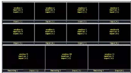
| window 9 input no: 9 Input (9) | window 10 input no: 10 Input (10) | window 11 input no: 11 Input (11) | |
| Input (9) | Input (10) | Input (11) | |
Figure 117: Preset8 - 11 windows (Preset8.OPx)
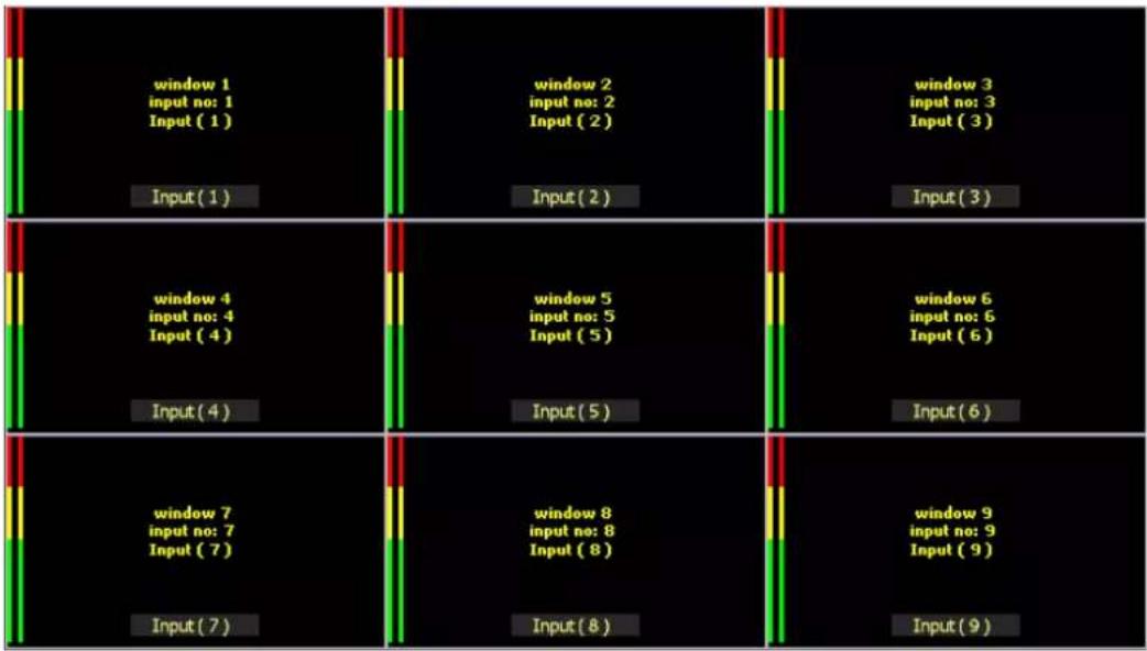
Figure 118: Preset9 – 9 windows with 2 audio meters and labels inside (Preset9.OPx)

Mi-16+ presets
The Mi-16+ can store up to 30 presets. It comes with 10 pre configured layouts as below,
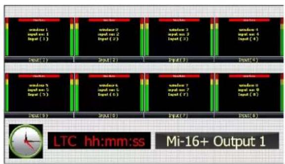

Figure 119: Preset1 – 8 windows on each output with Analog, digital clocks and Standalone Labels (Preset1.OPx)


Figure 120: Preset2 – 8 windows on each output, labels inside the windows (Preset2.OPx)

flowchart
graph TD
    A["Input 1<br>Input no. 1<br>Input (1)"] --> B["Output 2"]
    C["Input 2<br>Input no. 2<br>Input (2)"] --> D["Output 3"]
    E["Input 3<br>Input no. 3<br>Input (3)"] --> F["Output 4"]
    G["Input 4<br>Input no. 4<br>Input (4)"] --> H["Output 5"]
    I["Input 5<br>Input no. 5<br>Input (5)"] --> J["Output 6"]
    K["Input 6<br>Input no. 6<br>Input (6)"] --> L["Output 7"]
    M["Input 7<br>Input no. 7<br>Input (7)"] --> N["Output 8"]
    O["Output 9"] --> P["Output 10"]
    Q["Output 11"] --> R["Output 12"]
    S["Output 13"] --> T["Output 14"]
    U["Output 15"] --> V["Output 16"]
    W["Output 17"] --> X["Output 18"]

Figure 121: Preset3 – 7 windows on each outputs (Preset3.OPx)
flowchart
graph TD
    A["Input (1)"] --> B["window 1<br>Input not 2<br>Input (3)"]
    C["Input (2)"] --> D["window 2<br>Input not 2<br>Input (2)"]
    E["Input (3)"] --> F["window 3<br>Input not 3<br>Input (3)"]
    G["Input (4)"] --> H["window 4<br>Input not 4<br>Input (4)"]
    I["Input (5)"] --> J["window 5<br>Input not 5<br>Input (5)"]
    K["Input (6)"] --> L["window 6<br>Input not 6<br>Input (6)"]
    M["Input (7)"] --> N["window 7<br>Input not 7<br>Input (7)"]
    O["Input (8)"] --> P["window 8<br>Input not 8<br>Input (8)"]
    Q["hh:mm:ss<br>Camera Control"] --> R["Output"]
    S["Input (7)"] --> T["Output"]

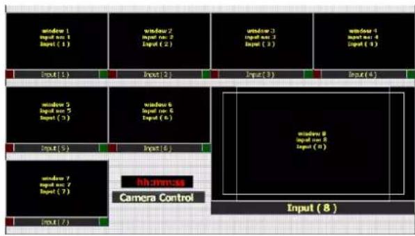
Figure 122: Preset4 – (Preset4.OPx)


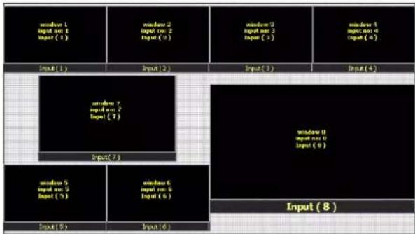
Figure 123: Preset5 – 15 windows (Preset5.0Px)
flowchart
graph TD
    A["Input (1)"] --> B["Input (2)"]
    B --> C["Input (3)"]
    C --> D["Input (4)"]
    E["Input (5)"] --> F["Input (6)"]
    G["Input (7)"] --> H["Input (8)"]
    I["Input (9)"] --> J["Input (10)"]
    K["Input (11)"] --> L["Input (12)"]
    M["Input (13)"] --> N["Input (14)"]
    O["Input (15)"] --> P["Input (16)"]
    Q["Input (17)"] --> R["Input (18)"]
    S["Input (19)"] --> T["Input (20)"]
    U["Input (21)"] --> V["Input (22)"]
    W["Input (23)"] --> X["Input (24)"]
    Y["Input (25)"] --> Z["Input (26)"]
    AA["Input (27)"] --> AB["Input (28)"]
    AC["Input (29)"] --> AD["Input (29)"]
    AE["Input (30)"] --> AF["Input (30)"]
    AG["Input (31)"] --> AH["Input (31)"]
    AI["Input (32)"] --> AJ["Input (32)"]
    AK["Input (33)"] --> AL["Input (33)"]
    AM["Input (34)"] --> AN["Input (34)"]
    AO["Input (35)"] --> AP["Input (35)"]
    AQ["Input (36)"] --> AR["Input (36)"]
    AS["Input (37)"] --> AT["Input (37)"]
    AU["Input (38)"] --> AV["Input (38)"]
    AW["Input (39)"] --> AX["Input (39)"]
    AY["Input (40)"] --> AZ["Output 1"]
    BA["Input (41)"] --> BB["Output 2"]
    BC["Input (42)"] --> BD["Output 3"]
    BE["Input (43)"] --> BF["Output 4"]
    BG["Input (44)"] --> BH["Output 5"]
    BI["Input (45)"] --> BJ["Output 6"]
    BK["Input (46)"] --> BL["Output 7"]
    BM["Input (47)"] --> BN["Output 8"]

flowchart
graph TD
    A["Input (16)"] --> B["Input (13)"]
    B --> C["Input (14)"]
    C --> D["Input (15)"]
    D --> E["Input (16)"]
    E --> F["Input (17)"]
    F --> G["Input (18)"]
    G --> H["Input (19)"]
    H --> I["Input (20)"]
    I --> J["Input (21)"]
    J --> K["Input (22)"]
    K --> L["Input (23)"]
    L --> M["Input (24)"]
    M --> N["Input (25)"]
    N --> O["Input (26)"]
    O --> P["Input (27)"]
    P --> Q["Input (28)"]
    Q --> R["Input (29)"]
    R --> S["Input (30)"]
    S --> T["Input (31)"]
    T --> U["Input (32)"]
    U --> V["Input (33)"]
    V --> W["Input (34)"]
    W --> X["Input (35)"]
    X --> Y["Input (36)"]
    Y --> Z["Input (37)"]
    Z --> A
    style A fill:#f9f,stroke:#333
    style B fill:#ccf,stroke:#333
    style C fill:#cfc,stroke:#333
    style D fill:#fcc,stroke:#333
    style E fill:#cff,stroke:#333
    style F fill:#ffc,stroke:#333
    style G fill:#cfc,stroke:#333
    style H fill:#fcc,stroke:#333
    style I fill:#cfc,stroke:#333
    style J fill:#fcc,stroke:#333
    style K fill:#cfc,stroke:#333
    style L fill:#fcc,stroke:#333
    style M fill:#cfc,stroke:#333
    style N fill:#fcc,stroke:#333
    style O fill:#cfc,stroke:#333
    style P fill:#fcc,stroke:#333
    style Q fill:#cfc,stroke:#333
    style R fill:#fcc,stroke:#333
    style S fill:#cfc,stroke:#333
    style T fill:#fcc,stroke:#333
    style U fill:#cfc,stroke:#333
    style V fill:#fcc,stroke:#333
    style W fill:#cfc,stroke:#333
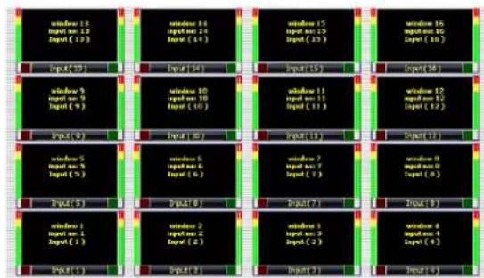
Figure 124: Preset6 – 16 windows (Preset6.OPx)

flowchart
graph TD
    subgraph Module1
        A1["window 1<br>input bus 1<br>Input (1)"]
        B1["window 2<br>input bus 2<br>Input (2)"]
        C1["window 3<br>input bus 3<br>Input (3)"]
    end
    subgraph Module2
        D1["window 4<br>input bus 4<br>Input (4)"]
        E1["window 5<br>input bus 5<br>Input (5)"]
        F1["window 6<br>input bus 6<br>Input (6)"]
    end
    subgraph Module3
        G1["window 7<br>input bus 7<br>Input (7)"]
        H1["window 8<br>input bus 8<br>Input (8)"]
    end
    subgraph Module4
        I1["Input (1)"]
        J1["Input (2)"]
        K1["Input (3)"]
    end

Figure 125: Preset7 – 16 windows with audio meters and tally LEDs (Preset7.OPx)
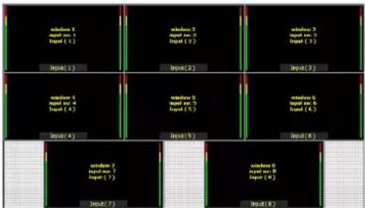
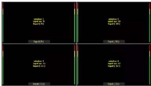
Figure 126: Preset8 - 12 windows with 2 audio meters (Preset8.OPx)

flowchart
graph TD
    subgraph_Input_1["Input (1)"]
        A1["window 1<br>input no 1<br>Input (1)"] --> B1["window 2<br>input no 2<br>Input (2)"] --> C1["window 3<br>input no 3<br>Input (3)"]
    end
    subgraph_Input_2["Input (2)"]
        A2["window 2<br>input no 2<br>Input (2)"] --> B2["window 3<br>input no 3<br>Input (3)"]
    end
    subgraph_Input_3["Input (3)"]
        A3["window 3<br>input no 3<br>Input (3)"] --> B3["window 4<br>input no 4<br>Input (4)"]
    end
    subgraph_Output_1["Input (8)"]
        A4["window 4<br>input no 4<br>Input (4)"] --> B4["window 5<br>input no 5<br>Input (5)"]
    end
    subgraph_Output_2["Input (8)"]
        A5["window 5<br>input no 5<br>Input (5)"] --> B5["window 6<br>input no 6<br>Input (6)"]
    end

Figure 127: Preset9 - 9 windows with 2 audio meters and labels inside (Preset9.OPx)

flowchart
graph TD
    A["Input(1)"] --> B["Input(2)"]
    B --> C["Input(3)"]
    C --> D["Output(4)"]
    E["Input(5)"] --> F["Input(6)"]
    F --> G["Input(7)"]
    G --> H["Output(8)"]
    style A fill:#f9f,stroke:#333
    style E fill:#f9f,stroke:#333
    style F fill:#f9f,stroke:#333
    style G fill:#f9f,stroke:#333
    style H fill:#f9f,stroke:#333

flowchart
graph TD
    A["Input (1)"] --> B["Window 1"]
    A --> C["Window 2"]
    A --> D["Window 3"]
    A --> E["Window 4"]
    A --> F["Window 5"]
    A --> G["Window 6"]
    A --> H["Window 7"]
    A --> I["Window 8"]
    B --> J["Input (9)"]
    C --> K["Input (10)"]
    D --> L["Input (11)"]
    E --> M["Input (12)"]
    F --> N["Input (13)"]
    G --> O["Input (14)"]
    H --> P["Input (15)"]
    I --> Q["Input (16)"]
    style A fill:#f9f,stroke:#333
    style B fill:#ccf,stroke:#333
    style C fill:#ccf,stroke:#333
    style D fill:#ccf,stroke:#333
    style E fill:#ccf,stroke:#333
    style F fill:#ccf,stroke:#333
    style G fill:#ccf,stroke:#333
    style H fill:#ccf,stroke:#333
    style I fill:#ccf,stroke:#333
Figure 128: Preset10 – 16 windows with 2 audio meters (Preset10.OPx)
Mi-16# presets


Figure 129: Preset1 – (Preset01.OPX)


Figure 130: Preset2 – (Preset02.OPX)


Figure 131: Preset3 – (Preset3.OPX)

flowchart
graph TD
    subgraph Input_1
        A1["window 1<br>input no. 1<br>input (2)"]
    end
    subgraph Input_2
        B1["window 2<br>input no. 2<br>input (2)"]
    end
    subgraph Input_3
        C1["window 3<br>input no. 3<br>input (3)"]
    end
    subgraph Input_4
        D1["window 4<br>input no. 4<br>input (4)"]
    end
    subgraph Input_5
        E1["window 5<br>input no. 5<br>input (5)"]
    end
    subgraph Input_6
        F1["window 6<br>input no. 6<br>input (6)"]
    end
    subgraph Input_7
        G1["window 7<br>input no. 7<br>input (7)"]
    end
    subgraph Input_8
        H1["window 8<br>input no. 8<br>input (8)"]
    end
    subgraph Input_9
        I1["window 9<br>input no. 9<br>input (9)"]
    end
    subgraph Input_10
        J1["window 10<br>input no. 10<br>input (10)"]
    end
    subgraph Input_11
        K1["window 11<br>input no. 11<br>input (11)"]
    end

Figure 132: Preset4 – (Preset4.OPX)

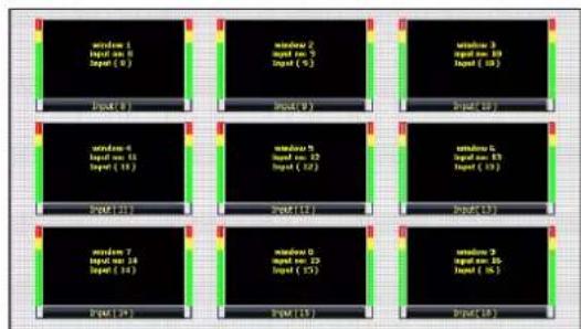
Figure 133: Preset5 – (Preset5.OPX)
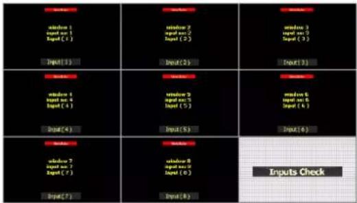

Figure 134: Preset6 – (Preset6.OPX)

flowchart
graph TD
    A["Input 1"] --> B["Window 1"]
    A --> C["Input 2"]
    A --> D["Input 3"]
    A --> E["Input 4"]
    F["Input 5"] --> G["Window 5"]
    F --> H["Input 6"]
    F --> I["Input 7"]
    F --> J["Input 8"]
    K["Input 9"] --> L["Window 9"]
    K --> M["Input 10"]
    K --> N["Input 11"]
    O["Input 12"] --> P["Window 12"]
    O --> Q["Input 13"]
    O --> R["Input 14"]
    S["Input 15"] --> T["Window 15"]
    S --> U["Input 16"]
    S --> V["Input 17"]
    W["Input 18"] --> X["Window 18"]
    W --> Y["Input 19"]
    W --> Z["Input 20"]
Figure 135: Preset7 – (Preset7.OPX)

flowchart
graph TD
    subgraph Inputs
        A["Input 1"] --> B["Input 2"]
        C["Input 3"] --> D["Input 4"]
        E["Input 5"] --> F["Input 6"]
        G["Input 7"] --> H["Input 8"]
        I["Input 9"] --> J["Input 10"]
        K["Input 11"] --> L["Input 12"]
    end

    subgraph Sources
        M["Input 1"] --> N["Input 2"]
        O["Input 3"] --> P["Input 4"]
        Q["Input 5"] --> R["Input 6"]
        S["Input 7"] --> T["Input 8"]
        U["Input 9"] --> V["Input 10"]
        W["Input 11"] --> X["Input 12"]
    end

    A --> C --> E --> G --> I --> K
    B --> D --> F --> H --> L --> X
    C --> N --> P --> Q --> R --> S
    D --> P --> R --> T --> U --> V
    E --> P --> R --> S --> X
    F --> R --> S
    G --> T --> X
    H --> Y["Source"]
    I --> Y
    J --> Y
    K --> Y
    L --> Y
    M --> Y
    N --> Y
    O --> Y
    P --> Y
    Q --> Y
    R --> Y
    S --> Y
    T --> Y
    U --> Y
    V --> Y
    W --> Y
    X --> Y
    Y --> Z["Source"]

Figure 136: Preset8 – (Preset8.OPX)

flowchart
graph TD
    subgraph Module_1
        A1["window 1<br>input no. 1<br>Input (1)"]
        A2["window 2<br>input no. 2<br>Input (2)"]
        A3["window 3<br>input no. 3<br>Input (3)"]
        A4["window 4<br>input no. 4<br>Input (4)"]
    end
    subgraph Module_2
        B1["window 5<br>input no. 5<br>Input (5)"]
        B2["window 6<br>input no. 6<br>Input (6)"]
        B3["window 7<br>input no. 7<br>Input (7)"]
        B4["window 8<br>input no. 8<br>Input (8)"]
    end
    subgraph Module_3
        C1["window 9<br>input no. 9<br>Input (9)"]
        C2["window 10<br>input no. 10<br>Input (10)"]
        C3["window 11<br>input no. 11<br>Input (11)"]
        C4["window 12<br>input no. 12<br>Input (12)"]
    end
    subgraph Module_4
        D1["window 13<br>input no. 13<br>Input (13)"]
        D2["window 14<br>input no. 14<br>Input (14)"]
        D3["window 15<br>input no. 15<br>Input (15)"]
        D4["window 16<br>input no. 16<br>Input (16)"]
    end
    subgraph Module_5
        E1["window(1)"]
        E2["window(2)"]
        E3["window(3)"]
        E4["window(4)"]
    end
flowchart
graph TD
    A["window 13<br>input sum 12<br>Input (1)"] --> B["Input (1)"]
    C["window 14<br>input sum 14<br>Input (1+)"] --> D["Input (1+)"]
    E["window 15<br>input sum 15<br>Input (2+)"] --> F["Input (1+)"]
    G["window 16<br>input sum 16<br>Input (3+)"] --> H["Input (1+)"]
    I["window 9<br>input sum 9<br>Input (9)"] --> J["Input (1)"]
    K["window 10<br>input sum 10<br>Input (10)"] --> L["Input (1)"]
    M["window 11<br>input sum 11<br>Input (11)"] --> N["Input (1)"]
    O["window 12<br>input sum 12<br>Input (12)"] --> P["Input (1)"]
    Q["window 5<br>input sum 5<br>Input (5)"] --> R["Input (5)"]
    S["window 6<br>input sum 6<br>Input (6)"] --> T["Input (6)"]
    U["window 7<br>input sum 7<br>Input (7)"] --> V["Input (7)"]
    W["window 8<br>input sum 8<br>Input (8)"] --> X["Input (8)"]
    Y["window 1<br>input sum 1<br>Input (1)"] --> Z["Input (1)"]
    AA["window 2<br>input sum 2<br>Input (2)"] --> AB["Input (2)"]
    AC["window 3<br>input sum 3<br>Input (3)"] --> AD["Input (2)"]
    AE["window 4<br>input sum 4<br>Input (4)"] --> AF["Input (4)"]
Figure 137: Preset9 – (Preset9.OPX)

flowchart
graph TD
    A["window 1<br>input port 1<br>Input (1)"] --> B["window 2<br>input port 2<br>Input (2)"]
    B --> C["window 3<br>input port 3<br>Input (3)"]
    D["Input (1)"] --> E["Input (2)"]
    E --> F["Input (3)"]
    G["window 4<br>input port 4<br>Input (4)"] --> H["window 5<br>input port 5<br>Input (5)"]
    H --> I["window 6<br>input port 6<br>Input (6)"]
    J["window 7<br>input port 7<br>Input (7)"] --> K["window 8<br>input port 8<br>Input (8)"]
    L["window 9<br>input port 9<br>Input (9)"] --> M["window 10<br>input port 10<br>Input (10)"]
    N["window 11<br>input port 11<br>Input (11)"] --> O["Input (1)"]
    P["Input (8)"] --> Q["Input (9)"]
    Q --> R["Input (10)"]
    S["Input (11)"] --> T["Input (11)"]

Figure 138: Preset10 – (Preset10.OPX)
Cable Pinouts

All rights reserved by APANTA LCC, Porland, Oregon, USA. No part of this document may be reproduced in any form or by any means without written permission from the product manufacturer. Changes are periodically made to the information in this document. They will be incorporated in subsequent editions. The product manufacturer may make improvements and /or changes in the product described in this document at any time.
All the registered trademarks referred to this manual are belonging to their respective companies.
WARRANTY STATEMENT
Apantac LLC (herein after referred to as "Apantac") warrants to the original purchaser of the products manufactured by Apantac (the "Product,") will be free from defects in material and workmanship for a period of three (3) year from the date of shipment of the Product to the purchaser.
If the Product proves to be defective during the three (3) year warranty period, the purchaser's exclusive remedy and Apantac's sole obligation under this warranty is expressly limited, at Apantac's sole option, to:
(a) repair the defective Product without charge for parts and labor or,
(b) provide a replacement in exchange for the defective Product or,
(c) if after a reasonable time, is unable to correct the defect or provide a replacement Product in good working order, then the purchaser shall be entitled to recover damages subject to the limitation of liability set forth below.
Limitation of Liability
Apantac's liability under this warranty shall not exceed the purchase price paid for the defective product. In no event shall Apantac be liable for any incidental, special or consequential damages, including without limitation, loss of profits for any breach of this warranty.
If Apantac replaces the defective Product with a replacement Product as provided under the terms of this Warranty, in no event will the term of the warranty on the replacement Product exceed the number of months remaining on the warranty covering the defective Product.
Equipment manufactured by other suppliers and supplied by Apantac carries the respective manufacturer's warranty. Apantac assumes no warranty responsibility either expressed or implied for equipment manufactured by others and supplied by Apantac.
This hardware warranty shall not apply to any defect, failure or damage:
a) Caused by improper use of the Product or inadequate maintenance and care of the Product;
b) Resulting from attempts by those other than Apantac representatives to install, repair, or service the Product;
c) Caused by installation of the Product in a hostile operating environment or connection of the Product to incompatible equipment;
- What's In The Box
- Key Features
- There are 3 models in the Mi-16 family
- General features for all Mi-16 series
- Mi-16 specific features
- Mi-16+ specific features
- Mi-16# specific features
- Specifications
- Rear Views
- Hardware boot up
- Software
- Changing the Mi-16 IP Address
- Configuring of the Mi-16 series
- Mi-16
- Mi-16+
- Mi-16#
- Common features and configurations
- Editing mode
- System level settings
- Set output timing
- Sources, Names, Tally and Other Setups
- Names
- TSL
- Tally Mode
- Tally attributes
- To start configuring the Input Source table
- Name the source
- Quick Settings
- Set Tally colors
- System Settings
- Audio reference settings
- Load presets
- Editing
- To delete a window
- Mi-16 series window styles
- How to insert a window
- Customizing Window Elements
- Set Window Objects
- Set Borders:
- Set Border Skins:
- Select Input Source.
- Set Safe Area
- There are two tabs
- Safe Area 1 and Safe Area 2
- Option
- Name
- Time Zone
- Clock faces
- Saving Default Layout
- Offline Mode
- Appendix
- Mi-16 presets
- Mi-16+ presets
- Mi-16# presets
- WARRANTY STATEMENT
- Limitation of Liability
Brand : Apantac
Model : Mi-16
Category : Network Equipment