VMAX IP G4 DW-VG416 - Video recorder Digital Watchdog - Free user manual and instructions
Find the device manual for free VMAX IP G4 DW-VG416 Digital Watchdog in PDF.


| Product Type | Network Video Recorder (NVR) |
| Brand | Digital Watchdog |
| Model | VMAX IP G4 DW-VG416 |
| Video Inputs | 16 IP camera channels (up to 12MP each) |
| Recording Resolution | Up to 4K (3840x2160) at 30 fps |
| Compression | H.265 / H.264 / MPEG4 |
| Hard Drive Bays | 2 x SATA (up to 10TB each) |
| Max Storage Capacity | Up to 20TB (total) |
| HDMI Output | 1 x HDMI v1.4 (up to 3840x2160) |
| VGA Output | 1 x VGA (up to 1920x1080) |
| Network Interface | 2 x Gigabit Ethernet RJ45 |
| USB Ports | 2 x USB 2.0, 1 x USB 3.0 |
| Power Supply | 12V DC, 5A (included adapter) |
| Power Consumption | Max 30W (without HDDs) |
| Dimensions (W x D x H) | 352 x 275 x 48 mm |
| Weight | 3.2 kg (without HDDs) |
| Operating Temperature | 0°C to 40°C (32°F to 104°F) |
| Operating Humidity | 10% to 90% (non-condensing) |
| Remote Access | Via web browser or mobile app (iOS/Android) |
| Supported Protocols | ONVIF, RTSP, HTTP, FTP, SMTP, DHCP, DDNS |
| Maintenance | Clean with dry, soft cloth; avoid liquids and solvents |
| Safety | No user-serviceable parts inside; refer to qualified technician |
| Spare Parts & Repairability | Contact Digital Watchdog support for authorized service |
Frequently Asked Questions - VMAX IP G4 DW-VG416 Digital Watchdog
User questions about VMAX IP G4 DW-VG416 Digital Watchdog
0 question about this device. Answer the ones you know or ask your own.
Ask a new question about this device
Download the instructions for your Video recorder in PDF format for free! Find your manual VMAX IP G4 DW-VG416 - Digital Watchdog and take your electronic device back in hand. On this page are published all the documents necessary for the use of your device. VMAX IP G4 DW-VG416 by Digital Watchdog.
USER MANUAL VMAX IP G4 DW-VG416 Digital Watchdog
Complete IP Video Solutions
| 9-channel NVR | 12-channel NVR | 16-channel NVR |
| DW-VG494P | DW-VG4128P | DW-VG41616P |
| DW-VG492T4P | DW-VG4122T8P | DW-VG4162T16P |
| DW-VG494T4P | DW-VG4124T8P | DW-VG4164T16P |
| DW-VG496T4P | DW-VG4126T8P | DW-VG4166T16P |
| DW-VG498T4P | DW-VG4128T8P | DW-VG4168T16P |
| DW-VG4910T4P | DW-VG41210T8P | DW-VG41610T16P |
| DW-VG49124P | DW-VG41212T8P | DW-VG41612T16P |
| DW-VG4916T4P | DW-VG41216T8P | DW-VG41616T16P |
| DW-VG41220T8P | DW-VG41620T16P | |
| DW-VG41232T8P | DW-VG41632T16P |
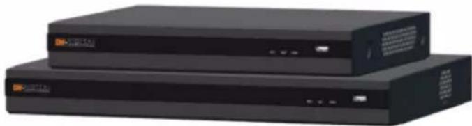
natural_image
Two black rectangular electronic devices with ports and indicator lights, no visible text or symbols on the surfaces.※ The picture might differ according to the specification and model.
※ Contents of this user manual are protected under copyrights and computer program laws.
Rev: 10/23
Before operating the system, please read this User Manual and retain it for future
reference.
WARNING
TO REDUCE FIRE OR SHOCK HAZARD, DO NOT EXPOSE THE UNIT TO RAIN OR MOISTURE.
The installation should be made by a qualified service person and conformed to all local codes.
Cautions
Read Before System Operation. Follow these details to prevent material damage or personal injury.
Signs of Caution and Warning

Warning: This sign indicates that the user could die or be seriously wounded if not used or installed properly.

Caution: This sign indicates that the user could be wounded or expect property damage if not used or installed properly.

Warning: Do not expose the product to fog, rain, or too much humidity to decrease the danger of electric shock or fire.
General Warning

Warning
- Use the power cord, which is supplied or recommended by the supplier, or it may cause a fire.
- Do not disassemble or reassemble the product. It may cause malfunction or fire.
- Enquire with your vendor about repair. It may cause electric shock or fire if the repair is not done properly.
- Do not touch the product with wet hands. It may cause malfunction or electric shock.
- Product installation must be ensured by a professional for product installation, or it may cause malfunction, electric shock, or fire.
- Ground applies to video products equipped with a 3-wire grounding type plug having a third (grounding) pin. This plug only fits into a grounding-type power outlet. If grounding is not done, it may cause malfunction or electric shock.
- Ground connection must not touch gas or water pipes or telephone lines. If grounding is not done properly, it may cause electric shock.
- Prevent metallic foreign substances from going inside the product. It may cause malfunction or electric shock.
- Do not spray insecticide or flammable spray while driving. It may cause a fire.
- Place the system in an open place where air ventilation is guaranteed, or it may overheat and cause considerable damage to the system.
- Prevent water from installing inside electrical parts. Clean with a dry towel or malfunction to avoid electric shock during cleaning.

Caution
- Use the power cord that is supplied or recommended by the supplier. The internal fan rotates at high speed and may cause an accident.
- Do not drop, give strong vibration, or shock the product. It may cause malfunction.
- The air intake in the front panel and air vent in the back panel must not be blocked during installation.
The internal temperature of the product would be greater than allowable and could cause malfunction or fire. - Do not touch the product or the power cord when there is thunder. It may cause an electric shock.
- Do not install the product near or on top of the heating source. The internal temperature of the product would be greater than allowable and could cause malfunction or fire.
- Do not install the product in an inclined or unstable location or where vibration could be committed. It may cause malfunction.
Cautions about the Power

Warning
- Must use the outlet of the grounding to connect the power cord, or it may cause a fire.
- Do not connect in the middle of the power cord or use an extension cord. It may generate heat or cause a fire.
- Do not touch the power cord with wet hands. It may cause an electric shock.
- Keep the power cord dry and protect it from humidity. It may generate heat or cause a fire. The power cord is not waterproof.
- Hold the body of the plug while removing the power. Do not pull the power cord. Damage to the power cord may cause overheating or a fire.
- Check the power plug regularly. Humidity and moderation in smoking may cause a fire.
- Remove the power cord from the outlet when the product is not used for a long time. It may cause short-circuit or electric shock.

Caution
- Do not turn off the power by removing the power plug. To turn off the power, click the power button from the front panel. When the system stops abnormally, the power button might not work. Click the power button for 5 full seconds to turn the power off.
- Do not cut off the power artificially, or shock or vibrate the unit while the HDD is active. It may cause hard disk failure or loss of data.

Remarks
※ Pictures and buttons, functions, or configurations are subject to change or modification per the different models.
Table of Contents
1. GETTING STARTED 6
1.1 CHECKING SUPPLIED ITEMS 6
1.2 SYSTEM STARTUP 7
1.3 SYSTEM SHUTDOWN 8
1.4 SYSTEM EXPLANATION....9
2. STARTUP WIZARD ....12
2.1 LANGUAGE....12
2.2 DATE/TIME 12
2.3 HDD FORMAT 13
2.4 NETWORK....14
2.5 CAMERA MANAGEMENT 16
2.6 PRODUCT REGISTRATION AND FINISH....17
3. OPERATION....18
3.1 USER LOG-IN 18
3.2 CAMERA REGISTRATION....18
3.3 DELETING CAMERAS....22
3.4 CAMERA SETUP 23
3.5 LIVE DISPLAY MODE 25
3.6 PTZ OPERATION....29
3.7 PLAYBACK RECORDED IMAGES 30
3.8 SEARCH RECORDED VIDEO 31
3.9 SMART SEARCH 35
3.10 SPECIAL CAMERA SEARCH 36
3.11 DST SETTING AND IMAGE PLAYBACK....37
3.12 MEGAPIX ^® IVA ^TM ANALYTICS 38
4. NVR SETTINGS MENU 42
4.1 SYSTEM 43
4.2 DEVICE....50
4.3 ALARM....59
4.4 RECORD....63
4.5 NETWORK....67
4.6 EXPORT 76
5. WEB SURVEILLANCE WITH WEB BROWSER....79
5.1 WEB LOGIN 79
5.2 WEB MONITORING....79
5.3 WEB PLAYBACK 80
5.4 NVR'S SETUP MENUS FROM THE WEB VIEWER 81
6. PATHFINDER CONNECTION THROUGH THE WEB....82
6.1 MYDW™ PATHFINDER™ LOGIN 82
6.2 LIVE 82
6.3 PLAYBACK 83
6.4 SETUP 83
7. Q & A 84
- SPECIFICATIONS 86
- WARRANTY INFORMATION......88
- LIMITS AND EXCLUSIONS....89
1. Getting Started
1.1 Checking Supplied Items
Make sure that you have the following items supplied with your NVR. If any of these items are missing or damaged, notify your vendor immediately. Keep the packing utilities for moving or storage purposes afterward.
| Items | Photo | Quantity |
| Quick setup guide and download instruction card |  | 1 |
| DW-VG49 and DW-VG412 : 48V D/C and power cable | 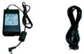 | 1 |
| DW-VG416 : 54V D/C and power cable | ||
| USB mouse | 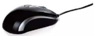 | 1 |
Note
USB keyboard input is not supported. Connect a USB mouse to use the virtual keyboard and interact with the NVR interface.
1.2 System Startup
1.2.1. Connect External Devices
Follow the diagram below to connect all necessary external devices to your NVR. Please note that the number of ports available may differ based on the model. See the product's specifications at the end of this manual for more information.
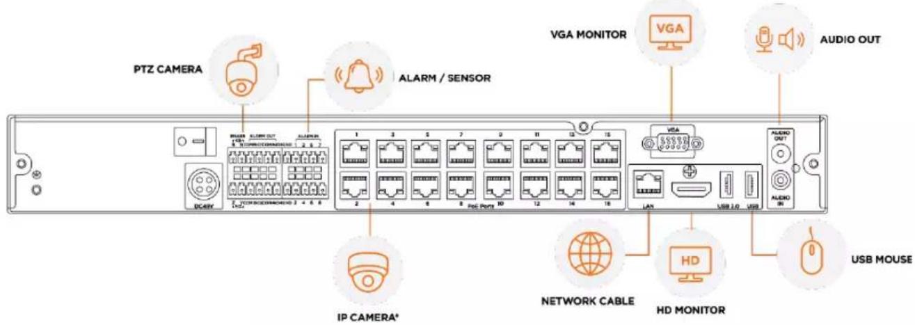
To prevent the NVR from overheating, do not operate it in an area that exceeds the maximum recommended ambient temperature of 104^ F ( 40^ C). To prevent airflow restriction, allow at least 3 inches (7.6 cm) of clearance around the ventilation openings.

* Back panel ports and location may differ according to the model. The model shown in the diagram above is the 16CH DW-VG416xT16P NVR.
** The audio input port in the NVR is disabled by default and will need to be configured in the NVR audio settings. For audio recording, use an IP camera with audio-input support or an external microphone.
1.2.2. System Startup
After connecting peripheral devices such as cameras, monitors and a mouse to the NVR, power up the NVR by connecting the DC48V adaptor/ power cable to the power jack on the rear panel. The boot logo will be displayed. Please wait until the boot process is complete.
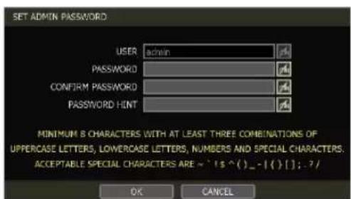
When the system is starting, the Set Admin Password window is displayed. When you log in to your unit for the first time, you will be asked to set up a new password. The password must be between 8 and 12 characters long, with a combination of at least one (1) each uppercase letter, lowercase letter, a number, and a special character. Acceptable special characters are \~‘!\$^()_-|{}[];?/’.
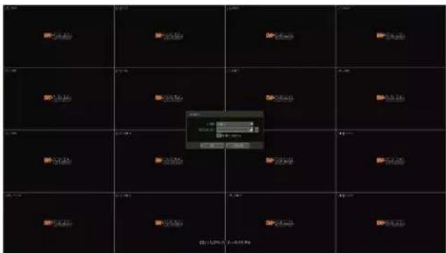
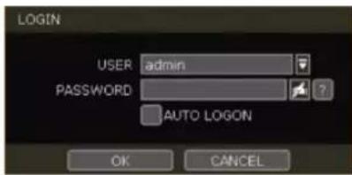
To login, right-click anywhere on the screen and enter the username and password in the popup screen. There is only one Administrator Account configurable in the NVR. It is assigned with an unchangeable User ID marked as 'admin'. The administrator account has full access to the NVR and its configurable
parameters and can also create new users and assign rights to the new user accounts. If the NVR is set to AUTO LOGIN, you will not need to enter the login every time you start the unit.
| Caution | 1) It may take a few minutes to start up the system after turning on the power in cases where the user sets the network configuration as DHCP mode but under the situation that there is no DHCP server in the network or the network is not connected.2) The mouse is included. In cases where you need to replace it, it is highly recommended to choose well-known major brands such as DELL, MICROSOFT, LOGITECH, or SAMSUNG. |
| Note | 1) Do not forget the administrator's password that was set for the first time. In cases where you have forgotten your password, contact your local dealer for help.2) Refer to “Section 4.1.2 User” for AUTO LOGIN and AUTO LOGOFF settings. |
1.3 System Shutdown
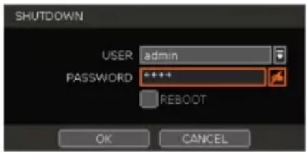
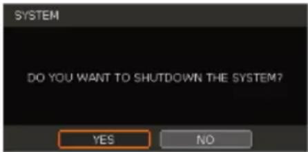
To shut down the NVR, click the exit button [☐] on the Toolbar at the bottom of the screen then click [SHUTDOWN] in the pop-up screen as shown below. To avoid potential electrical damage, do not disconnect power to the NVR by disconnecting the power plug from the NVR while in operation.
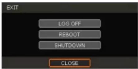
When prompting a SHUTDOWN, input the administrator password and click [OK] to shut down the system. Click [YES] to confirm shutdown.
Note
Users can input passwords by using a mouse and the virtual keyboard.
1.4 System Explanation
1.4.1. Front Panel
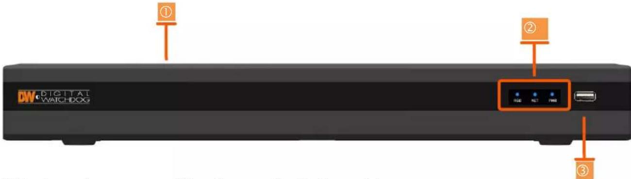
** Front panel may appear differently according to the model.
- Power switch (located on the back panel)
- LED indicator: indicates system status for power, recording activity and network status.
- USB port: for backup and upgrade.
1.4.2. The Toolbar in Live Mode
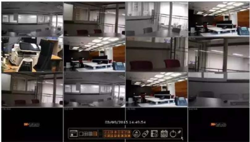
In Live View, move the mouse cursor to the bottom of the screen to show the menu bar.
Menu

Click on the menu button to access NVR's main menu screen. See section "4. Setting" for details.
Display Mode
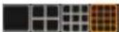
Select the preferred display mode from 1CH, 4CH, 9CH, or 16CH split screen mode options.
Sequence

Start/stop the sequencing mode in Live Mode to cycle camera displays in the viewing layout. The sequence is disabled if all channels are displayed.
Channel
Switch to a single-channel view of a specific channel by selecting the corresponding channel number.
Emergency Recording

The system records all channels with the full-frame rate at the maximum resolution regardless of the recording setting. To stop the emergency recording, click the same icon again.
Backup

Backup recorded video to an external device. See "4.6 Export" for details.
Playback

Switch to Playback Mode. See "3.7 Playback Recorded Image" for details.
Search

Open the search options screen. See "3.8 Search Recorded Image" for details.
Exit

Exit the NVR with three different options: Log Off, Reboot and Shutdown.
Pin

When selected, the NVR's menu bar remains on the screen permanently.
1.4.3. The Toolbar in Playback Mode
In the Playback View, move the mouse cursor to the bottom of the screen to show the menu bar.
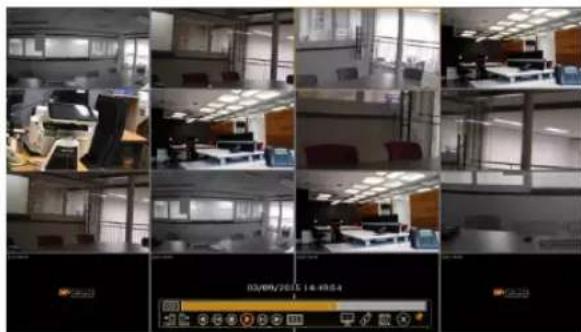
natural_image
Collage of office interior photos showing various workstations and equipment, with a digital display panel at bottom (no readable text or symbols)Channel

Indicates the currently selected channel.
Intelligent Search Bar

Shows recording status for the selected channel from 00:00 to 24:00. A white-vertical line indicates the time currently displayed. Moving the white-vertical line will update the video while seeking.
Previous/Next Date Search

Users can move to the previous date or the next date to search through recorded footage.
Playback Controls

: Playback speed control. (x32 / x16 / x8 / x4 / x2).

: Move backward one frame

: Stop button

: Play button

: Move forward one frame

: Playback speed control. (x2 / x4 / x8 / x16 / x32)

: Current playback speed
Screen Display Mode

Select the preferred display mode from 1CH, 4CH, 9CH, or 16CH split screen mode options.
Backup

Backup recorded video to an external device. See "4.6 Export" for details.
Playback

Switch to Playback Mode. See "3.7 Playback Recorded Image" for details.
Exit

Close Playback Mode and move to Live Mode.
Pin

When selected, the NVR's menu bar remains on the viewing screen, regardless of the mouse's position. Deactivate the Pin to undo this setting.
2. Startup Wizard
When the NVR is launched for the first time, the STARTUP WIZARD will appear. This wizard helps you set up the NVR's most basic settings for proper functioning. You can access the Startup Wizard screen at any time by clicking the Startup Wizard [START] button in setting the "MENU>SYSTEM>SETTINGS" menu. (See "4.1.5 SETTINGS").
Note
Only the ADMIN user can access the startup wizard.
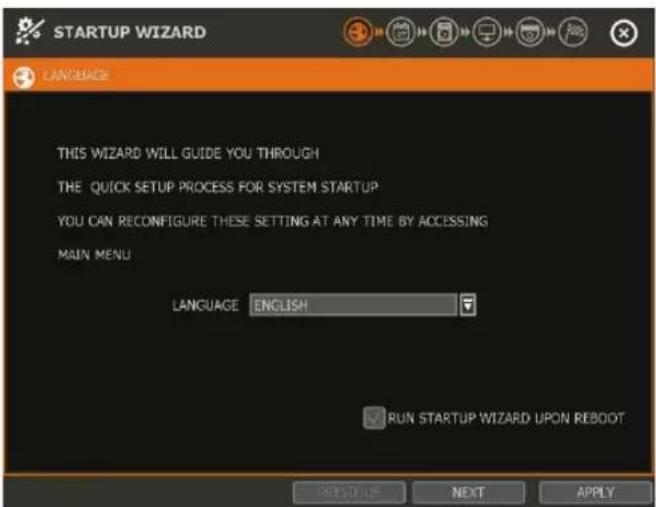
2.1 Language
Select the language according to the country or user's preference.
If "RUN STARTUP WIZARD UPON REBOOT" is selected, the Startup Wizard will pop up every time the system is started.
2.2 Date/Time
Select the NVR's date and time format, select the Time Zone, enable or disable daylight savings and sync the NVR with an NTP server or manually enter the date and time. You can also select to synchronize the NVR with an NTP server, which will automatically sync your NVR's date and time settings.
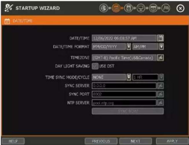
TIME SYNC MODE
There are four types of time sync modes:
- Server Mode: The operating NVR is set as a Time Sync Server, which can synchronize the time settings of other NVR(s) that are connected to it over the same network.
- Client Mode: Input the IP address of a designated NVR or a PC using Remote Software (C3 CMS) that is serving as a Time Sync Server in "SYNC SERVER". The NVR's time clock will be synchronized with the designated server by updating at regular time intervals as set in the "TIME SYNC CYCLE" setting.
- NTP Server Mode: "pool.ntp.org" is the recommended NTP Server. To activate, set the TIME ZONE of your local area then click [SYNC NOW].
• GPS Mode: Connect USB type GPS device and click [SYNC NOW]
2.3 HDD Format
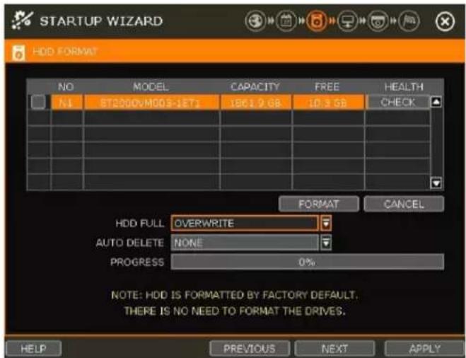
Digital Watchdog's NVRs are shipped with pre-installed HDDs that are formatted and ready to be used. There is no need to format the HDDs out of the box.
Note
If you have purchased an NVR without local storage included, you will need to format the HDDs after they have been installed to the NVR.
HDD FULL
Select "Overwrite" or "Stop recording" when HDD is full.
• Overwrite: NVR deletes the oldest data and records new data.
- Stop recording: NVR stops recording.
HDD CHECK
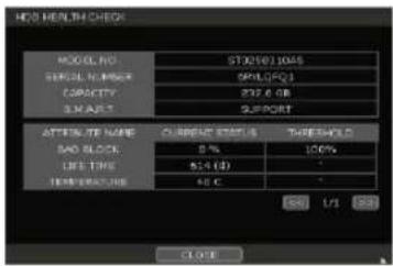
Click (CHECK) next to each HDD to view full information of each HDD such as model name, serial no, capacity, bad sector ratio, lifetime (used time) and temperature.
HDD FORMAT
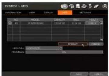
Check the box next to the HDDs you wish to format and press the "FORMAT" button. If system resources are currently occupied (such as network connection) during the format process, the format process may fail. It is recommended to reboot the system to release system resources and then try to format again.
AUTO DELETE
Set the period when the HDD will automatically delete all recorded data. Select from None (default) up to 366 days.
Note
- It may take a few minutes to format the HDD.
- When the format is done, all data in the HDD will be deleted.
- The system always reserves some space in each built-in HDD to effectively utilize archiving memory.
2.4 Network
Set up the NVR's network settings for remote connection.
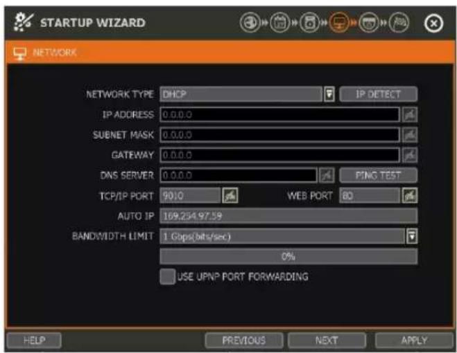
NETWORK TYPE
Select either STATIC IP or DHCP for dynamic IP. For proper configuration, it is recommended to assign the NVR a DHCP address and let the NVR auto-discover all the proper network settings, and then change the Network Type to Static IP and save the changes.
- DHCP: the NVR will automatically configure the network settings according to the current network requirements. If DHCP is selected, click the 'IP DETECT' button to automatically detect all the network settings.
- STATIC IP: manually enter all necessary network settings. While set to STATIC, the network settings will not change when prompted by the connected DHCP router or DHCP network device.
IP ADDRESS
Displays the NVR's IP address. If DHCP is selected, the IP address will automatically adjust to match the network's requirements. If STATIC is selected, the IP address can be manually changed as needed.
SUBNET MASK
Subnet Mask address classifies the subnet that the system belongs to. For more information, please consult your network administrator or your Internet provider.
GATEWAY
This is the IP address of the router or gateway server. It is required when connecting to the NVR through the external router over the Internet (from another network). For more information, consult your network administrator or your Internet provider.
DNS SERVER
Enter the IP address of the Domain Name Server. Input the DNS Server information to use DDNS, Email Notifications and NTP Server. For more information, please consult your network administrator or your Internet provider.
TCP/IP PORT
(Default - Port 9010) Input the network port number that is used when connecting to the NVR locally or remotely. If your ISP blocks Port 9010, you may either port forward the blocked port or change to use a different valid port number (ex, 9020). If there are multiple NVRs connected to the same local network, it should be considered to assign each NVR to different TCP/IP Ports.
WEB PORT
(Default - Port 80) Input the port number to use when connecting with a Web Browser. If your ISP blocks Port 80, you may either port forward the blocked port or change to use a different valid web port number (ex, 8080). If there are multiple NVRs connected to the same local network, it should be considered to assign each NVR to different Web Ports.
AUTO IP
Displays the system IP which is assigned through Auto-IP automatically.
BANDWIDTH LIMIT
(Default - 100 Mbps) Depending on the setting made by the user, the system can control the data volume transmitted over a network ranging from 25 kbps up to 1Gbps. This function is effective when under narrow bandwidth network conditions or when the user wants to limit “network bandwidth occupied by video transmission” to a certain level.
USE UPnP (Universal Plug and Play)
UPnP (Universal Plug and Play) Port Forwarding: If a UPnP supported router is connected, the NVR will forward ports automatically after communicating with the router without the need for complicated port forwarding setup at the router.
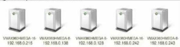
Once the PC has discovered the NVR using Network Discovery, double-click on the icon to open the NVR's web client. Enter the User ID and Password that is used to log in to the NVR then click 'Connect'.
Note
-
The maximum number of simultaneous remote connections is 15 users.
-
For the other network settings, such as DDNS, Notification, Mobile Push & PathFinder, please refer to the "4.5 Network".
2.5 Camera Management
The Camera Management menu allows you to search, register and manage your IP cameras. See "3.2 Camera Registration" for more information.
![STARTUP WIZARD CAMERA MANAGEMENT AUTO CONFIGURATION SELECT A RECORDING MODE AND PRESS [START] BUTTON. CONTINUOUS START DRAG & DROP CONFIGURATION FIND AND CONFIGURE ALL CAMERAS AND LAYOUT MANUALLY START HELP << ADVANCED PREVIOUS NEXT APPLY START STARTUP WIZARD CAMERA MANAGEMENT CAM ON/OFF PROTOCOL IP ADDRESS MODEL NAME SETUP DEL 1 ON R/Y US 20.0.10 IP-2141 ROUTE SETUP 2 ON 3 ON 4 ON 5 ON 6 ON << CH 1~6 >> HELP << BACK PREVIOUS NEXT APPLY](/content/2026/05/1062179/images/6b872ea7e1b7123ace995699c1a8eb6ba5d5d87cabbe0195aeea4ad5ddaaf722.jpg)
Auto-Configuration (1)
The NVR will scan the network for all supported cameras and automatically register detected cameras to the available channels. Select the recording mode to apply to all registered cameras and press [START]. The NVR will search for all cameras under the same network (Router) and register them in order, automatically.
In cases where there are multiple NVRs on the network, it is recommended to use the Drag & Drop or advanced configuration options to avoid a camera being connected to multiple NVRs.
Drag & Drop Configuration (2)
The Drag & Drop Configuration scans the network for supported cameras, displaying the results in a table from which you can manually drag-and-drop cameras into the viewing channels to assign them to specific channels.
- Click the [START] button to search for the camera.
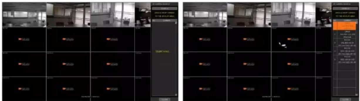
- Select a camera and while clicking on the camera, drag it to a channel to assign it.
- Click the [APPLY] button to finish the process.
Advanced Configuration (3)
Search the network for cameras and manually configure and register them to the NVR.
2.6 Product Registration and Finish
Register the NVR and user information for technical support and maintenance.
![STARTUP WIZARD FINISH STARTUP WIZARD HAS BEEN COMPLETED SUCCESSFULLY. CLICK [FINISH] BUTTON TO EXIT THE STARTUP WIZARD. IF YOU MADE ANY ERRORS OR FIND MISSING DATA, CLICK [PREVIOUS] BUTTON TO RETURN TO THE PREVIOUS SCREEN. REGISTER YOUR PRODUCT PREVIOUS NEW FINISH](/content/2026/05/1062179/images/b4abb33f1721d176a5027d755d7c7d3496dee9aaa68b9be9b4ec8c5a00f146b4.jpg)
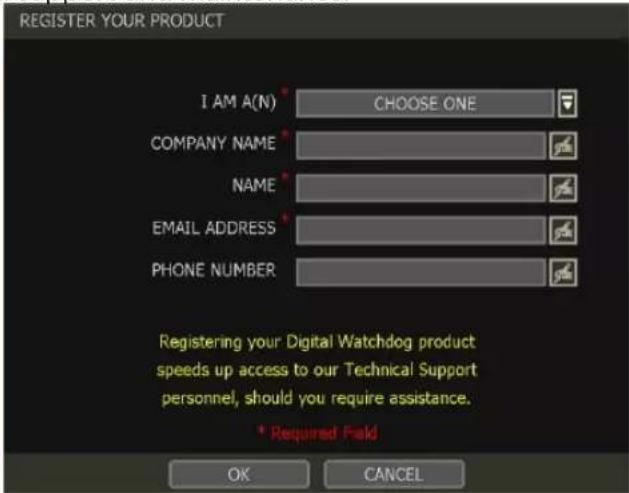
When the setup wizard is completed, click "FINISH" to close and go to the live viewing screen.
3. Operation
3.1 User Log-in
Input the USER and PASSWORD credentials to log in after turning on the system. If a user forgets their password, they may click the 🔒 icon to check the password hint.
![CLOSE 1 2 3 4 5 6 7 8 9 0 - - <- 0 W e r t Y u i o p [ ] CLR a s d r c h j k l : * ENTER SHIFT ? x c v h n m , / SHIFT CAPS LOCK: SPACE ... SHIFT LOCK](/content/2026/05/1062179/images/b4bf67b145c1893b4493c067dea898aa72e6badb924315df7683949352ba2c9a.jpg)
Note 1) LOGIN window will be permanently displayed until a user logs in with the right USER and Password. 2) If NVR is set to use AUTO LOGIN, the login process is will not be prompted whenever the system is powered on. See "Section 4.1.2 User" for more information.
Note
The key in the virtual keyboard includes often used words, such as Admin, root, http://, rtsp://, www., .com, .net, .org etc.
3.2 Camera Registration
The NVR can connect to any ONVIF® IP cameras over the network. If the cameras are connected to the PoE switch in the back of the NVR, the cameras will also receive power and send data to and from the NVR.
Note
As part of the cybersecurity settings of the NVR, the VMAX IP G4 will assign passwords automatically to new DW IP cameras that are added with a blank password. If a camera is added to the NVR for the first time, without having its password set from the IP Finder™, the NVR will automatically assign it a new password. If the camera then needs to be connected to another NVR or system, users will need to reset the camera's settings.
3.2.1. PoE Camera Connection
PoE cameras are automatically connected when the camera is plugged into the PoE port. Channels assigned to cameras connected directly to the NVR's PoE switch will display the channel title in green. Cameras connected to the NVR's PoE switch must be set to 'DHCP' before being connected to the NVR. For cameras that support 'Auto IP', the NVR will automatically control its IP settings.
| Note | If a PoE camera is connected to the PoE channel where another camera has already been virtually assigned to that channel, the virtually assigned camera will be moved to another channel and the PoE camera will be assigned to that channel. |
| Note | Zero-Configuration is the Link-Local IP address assignment method through Auto-IP and is for automatically assigning IP addresses when DHCP is otherwise not available or supported. The device that adopts this technology selects an IP of 169.254.xxx.xxx and assigns the IP address after checking the availability of the selected IP address. |
3.2.2. Camera Connection through Network
![RECORD > CAMERA MANAGEMENT CAMERA MANAGEMENT RECORDING SCHEDULE QUICK SETUP AUTO CONFIGURATION SELECT A RECORDING MODE AND PRESS [START] BUTTON. CONTINUOUS START DRAG & DROP CONFIGURATION PIND AND CONFIGURE ALL CAMERAS AND LAYOUT MANUALLY START HELP << ADVANCED SAVE CANCEL RECORD > CAMERA MANAGEMENT CAMERA MANAGEMENT RECORDING SCHEDULE QUICK SETUP 3.4 CAM ON/OFF PROTOCOL IP ADDRESS MODEL BRAND SETUP DEL 1 ON FEATURES 200.0.30 202.41 HOUS SETUP X 2 ON 3 ON 4 ON 5 ON 6 ON << 1-6 >> DELETE PAGE DELETE ALL AUTO RESCAN WHEN CAMERA IP IS CHANGED ADD CAMERAS MANUAL Y HELP << BACK SAVE CANCEL](/content/2026/05/1062179/images/af520ee39c12136a95eb6acb75a8c8b16c8306e23c3f5778e1d0dc34346e1da9.jpg)
The NVR supports three different methods to search and register cameras on the local network (not directly connected by PoE) to the NVR.
- Auto Configuration: allows the NVR to scan the network and automatically register the first cameras it finds to the available channels.
- Drag & Drop Configuration: scans the network for supported cameras, displaying the results in a table from which you can drag cameras to the viewing channel to assign them to channels.
- Advanced Search: settings and manually adding cameras, select SEARCH.
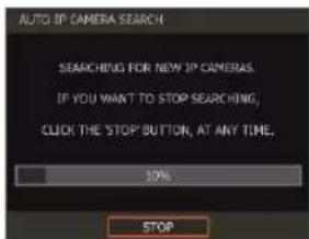
3.2.2.1. Auto Configuration
- Select a recording mode for the cameras. This recording option will be applied to all cameras registered to the NVR.
- Click [START]. The NVR will search all cameras under the same network (subnet) and automatically register them in the order that they are discovered.
3.2.2.2. Drag and Drop Configuration
- Click the [START] button to search for cameras. The NVR will search the network for cameras and display all results in the table on the right.
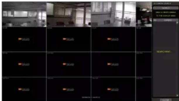
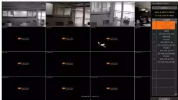
- Select the camera in the list and drag and drop it to the channel you want to assign to the camera. (While moving, the mouse pointer is changed to 📄.)
- Click [APPLY] to save all changes.
3.2.2.3. Advanced Search
The Advanced Configuration menu allows you to search for cameras with advanced configuration options, manage assigned cameras and manually add cameras using individual URLs.
- Click [SEARCH] to automatically search for all cameras on the network.
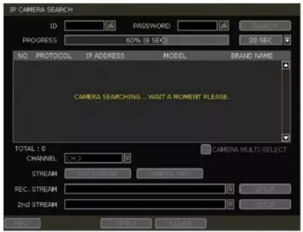
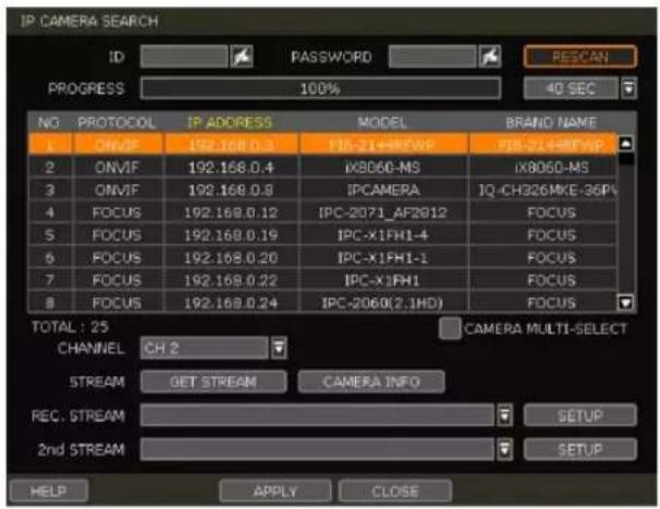
- Select a camera from the list and click [GET STREAM] to read the streams of the camera.
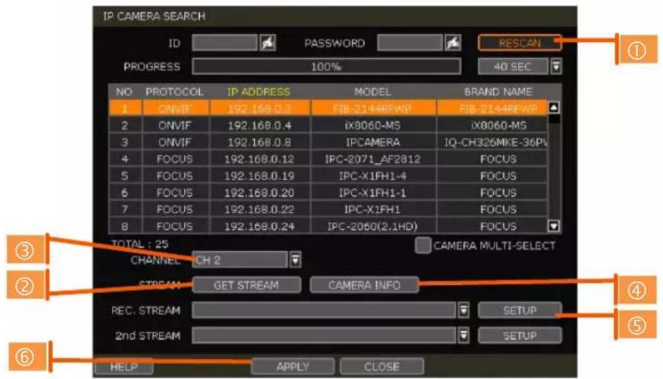
- When [GET STREAM] is selected, the NVR will assign a channel number to the selected camera. Users can also select a specific channel number from the drop-down options.
- [CAMERA INFO] shows the camera's basic information such as model name, IP address, Port number, and MAC address in detail.
- [SETUP] allows users to control the camera's settings such as Resolution/Frame/Bitrate/Image Quality etc.
- Click [APPLY] to register the selected camera to the NVR.
3.2.2.4. Multi-Select
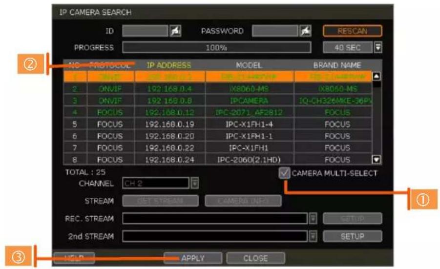
- Check the box next to [CAMERA MULTI SELECT] to select multiple cameras from the search results. Selected cameras will be highlighted in green.
-
Once all search results are displayed, the user can sort the table by the different columns such as protocol, IP Address, Hardware and Name, by clicking each property tab. The selected property will be highlighted in yellow.
-
Check the box next to [CAMERA MULTI SELECT] to select multiple cameras from the search results. Selected cameras will be highlighted in green.
-
When the [APPLY] button is clicked, cameras will be registered one by one starting from the top. Cameras that are already registered will be shown as unselected.
Note During the registration process of Camera Multi-Select, if there is a camera that has a different IP range or requires ID & Password, the process is paused, and the NVR will request the required information.
3.2.2.5. Manually Add Cameras
If a user wants to connect to an IP camera in a different network, the cameras can be added manually using the [ADD CAMERAS MANUALLY] button.
- Click [ADD CAMERAS MANUALLY] to open the camera property window.
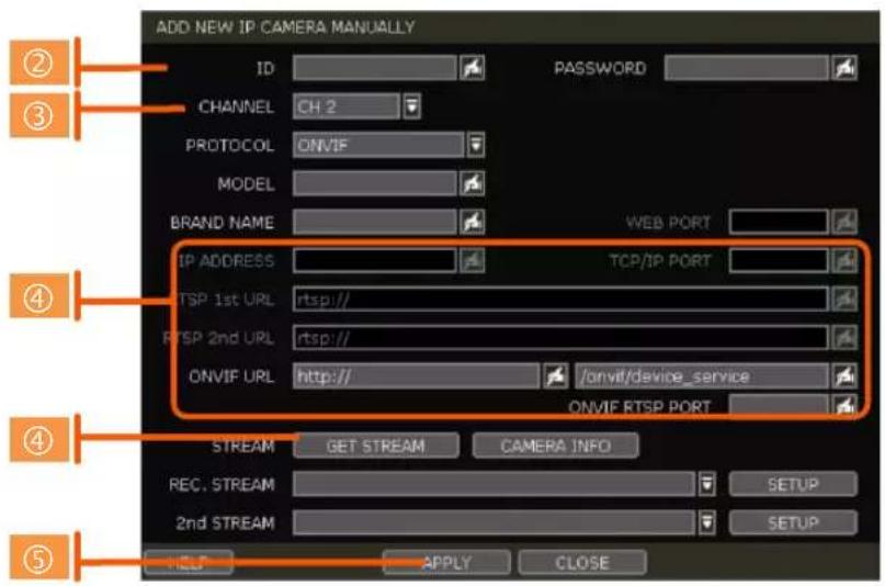
-
Select the channel number to register.
-
Select the protocol (ONVIF and RTSP) of the camera. Registration is available with one of the following. - IP Address, RTSP URL, or ONVIF URL
-
Input necessary information with the 📄 button and click the [GET STREAM] button to get stream information.
-
Click the [APPLY] button to register the camera.
3.3 Deleting Cameras
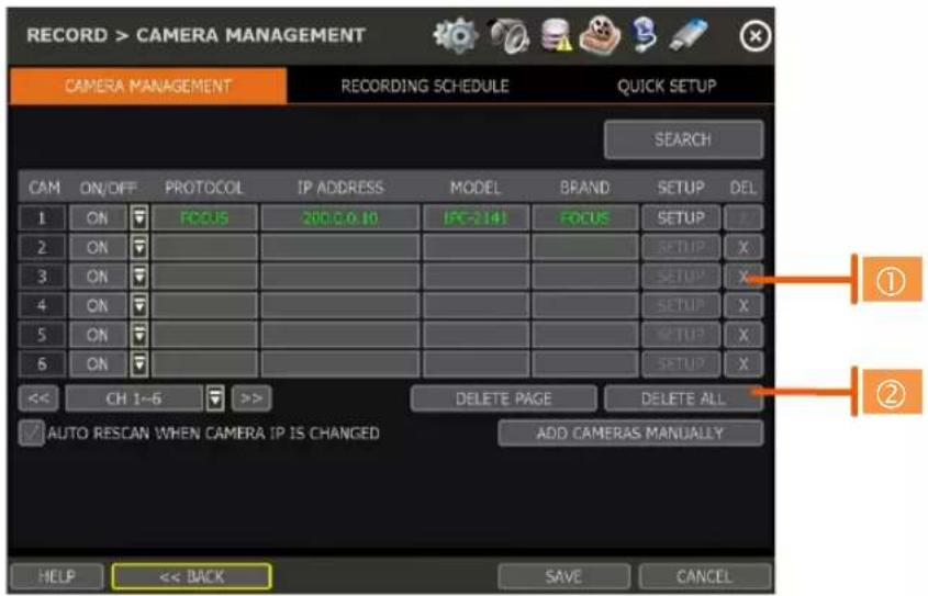
To delete a camera, go to Advanced Configuration by clicking [ADVANCED] in Camera Management (Menu > Record).
-
Non-PoE Camera - Delete (✗) button is always activated. Click ✗ on the camera to delete it from the NVR's channels.
-
PoE Camera - PoE cameras cannot be deleted while connected to the NVR's PoE switch. To delete a PoE camera, unplug the camera from the NVR and click the ✗ button when it is activated.
3.4 Camera Setup
Users can change the stream setup of registered cameras.
3.4.1. Setup for Each Camera
Go to Advanced Configuration by clicking [ADVANCED] in Camera Management (Menu > Record). Go to setup mode by clicking the [SETUP] button next to the desired camera. You can also access the camera's setup menu by right-clicking on a camera channel during live viewing and selecting [CAMERA SETUP].
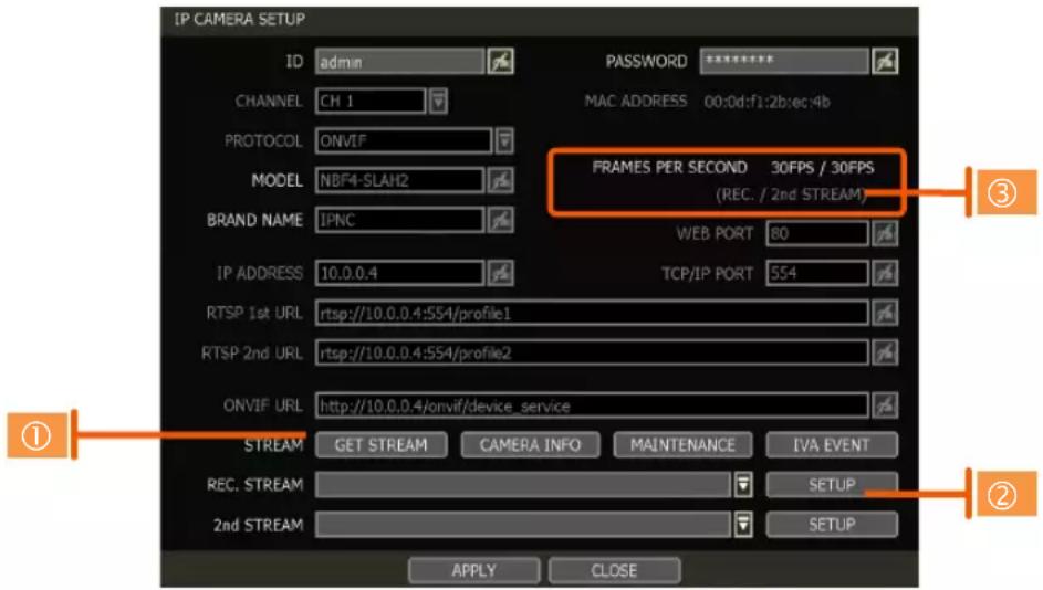
- Click the [GET STREAM] button and get the current camera streaming status.
-
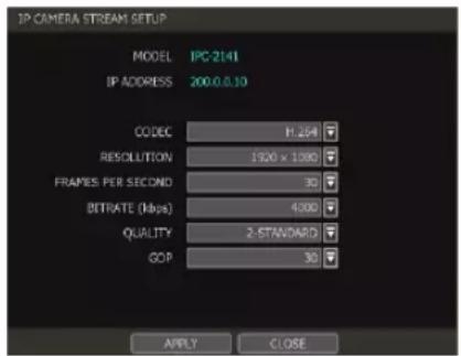
Click the [SETUP] button to change resolution, frame rate, image quality, etc.
-
RESOLUTION: Select the rescoring resolution from the available drop-down options.
- FRAMES PER SECOND: Set the stream's frames per second speed from 0 to 30.
- BITRATE: The maximum bitrate that the camera can use for image transmission.
- QUALITY: Image quality for recording. The higher the quality, the larger the recording file size will be.
• GOP: Group of pictures. The interval of I-Frame.
- Current Streaming conditions - This will display the camera's recording mode and FPS in real time.
• FRAMES PER SECOND: Shows the current transmission frame.
• REC.: Shows the stream that NVR records for the camera.
Note CCIP™ Encryption Option
CCIP™ (Closed Circuit Internet Protocol) System Encryption Protects Your Surveillance System from Out of Network Attacks.
Digital Watchdog's CCIP feature encrypts the RTSP stream using a TLS cryptographic protocol, adding a layer of security and end-to-end encryption. CCIP encryption works by the VMAX IP G4 system sending a request to encrypt the stream from the camera. The camera then encrypts its RTSP stream a second time in addition to requiring the user ID and password to authenticate. The result is a secured and encrypted RTSP stream that can be read-only through the requesting VMAX IP G4 NVR.
If you are using a Digital Watchdog camera that supports the CCIP encryption option, check the button on the camera's setup page as shown (※).
When enabled, images from the camera will be seen through the current NVR only.
3.4.2. Quick Setup
Users can set up multiple cameras with the same recording settings simultaneously.
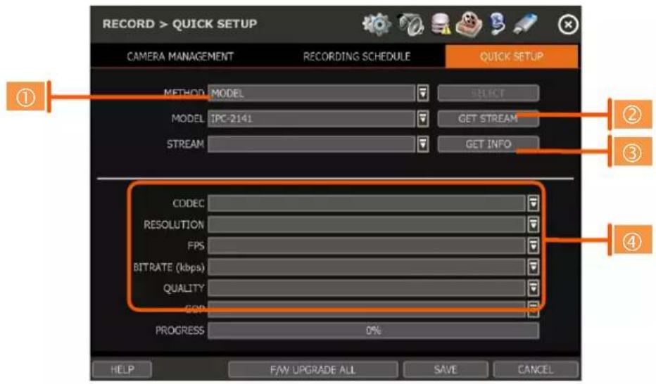
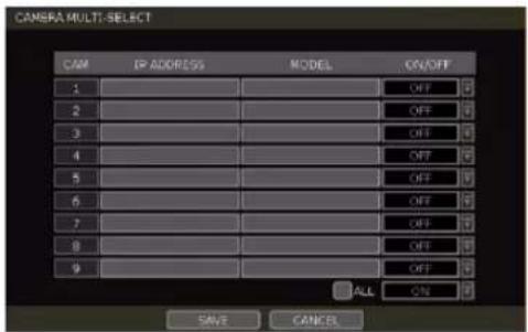
- Select the model or camera multi-select for Quick Setup. When selecting 'Model' for the Method, all cameras with the same model's name will be selected.
- When selecting 'Camera multi-select', the user can select which cameras to set. If you set the desired cameras to 'ON', the user can set up the settings of the selected cameras.
- Click the [GET STREAM] button and get the current stream information.
- Click the [Get INFO] button and check the current setup for the cameras.
- Change setup and click [SAVE].
- "CAMERAS ARE SUCCESSFULLY APPLIED" message will appear when the process has been completed.
3.4.3. Change Channel
ADMIN users can reassign camera channels by dragging & dropping cameras in the live display screen.
flowchart
graph TD
    A["[2:P1"] CH2] --> B["Channel No."]
    A --> C["PoE Port No."]
    A --> D["Channel Title"]
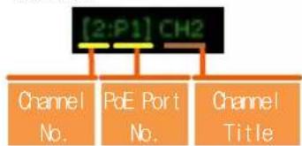
Select a camera by clicking-and-dragging it to its new channel. While dragging a camera, the mouse pointer will change to 📄. In the case of a PoE camera, the connected PoE port number and currently assigned channel will be shown as in the example below.
In Live Mode, users can check the status of PoE cameras by selecting the [PoE STATUS] menu.
Note
Only the ADMIN user can change the channel allocation.
3.5 Live Display Mode
3.5.1. Channel Selection
Live camera images will display after powering ON the NVR. The images can be displayed in 1, 4, 9 and 16 split-screen options (some split options may not be available depending to the maximum number of
channels of the NVR). Whenever the screen display mode button (☐) on the Toolbar is clicked, the screen will change to display the next channel or sequence of channels.
To switch from a multi-channel view to a full-screen, single camera display, double-click on the selected channel. To return to the previous screen mode, click the left mouse button again.
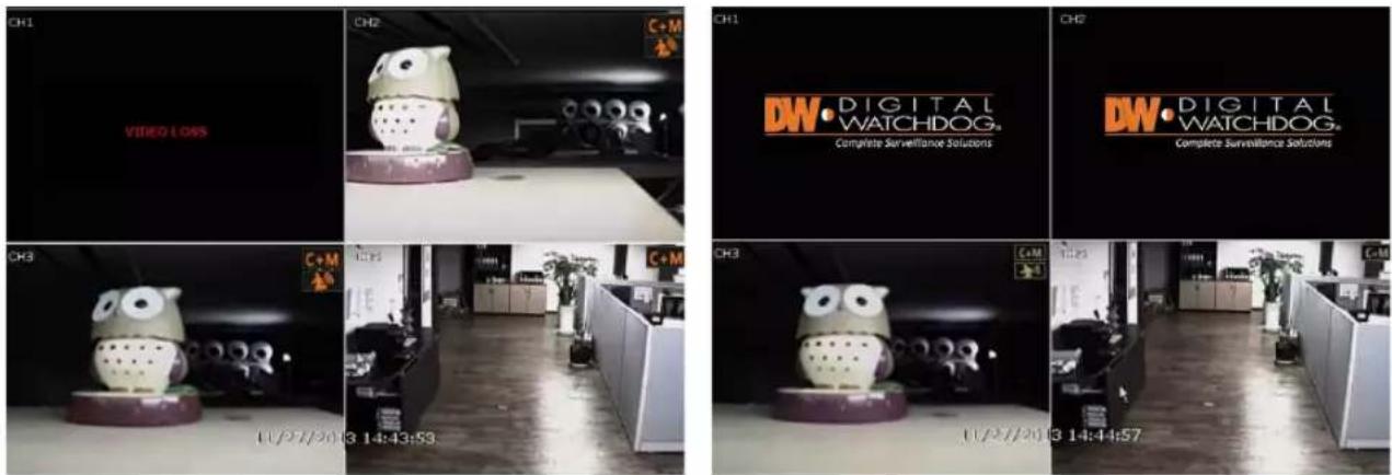
A “VIDEO LOSS” message will display on the screen when no camera is connected or if a camera is disconnected suddenly. When a camera is disconnected, a warning sound will emit, depending on the system’s event alarm settings.
Admin users can set various levels of authorization for each user, to grant or exclude viewing access to specific channels. If a certain user is not authorized to view a channel, the image will be unavailable within the viewing screen and the DW logo will show instead of Live video as shown in the example below.
3.5.2. Icons
In Live Mode, icons will appear on the screen to notify of the system mode or status.
| The icons shown at the right-upper corner of each channel screen | The icons shown at the right-bottom corner on full-screen mode | ||
 | Continuous Recording |  | No HDD detected |
 | Motion Detection Recording |  | Emergency Recording is in use |
 | Sensor Activated Recording |  | PTZ is enabled |
 | Continuous + Motion Alarm Recording |  | Warning for exceeding temperature |
 | Continuous + Sensor Activated Recording |  | Sequence Mode is enabled |
 | Motion Detection + Sensor Activated Recording |  | Digital Zoom is enabled |
 | Emergency Recording | ||
 | Sensor Activated | ||
 | Motion Detected | ||
 | Audio Channel | ||
 | PTZ Camera | ||
 | Transaction Verification | ||
Note If you cannot find any recording icon in the right corner of the screen, then the system is not recording. Check the recording schedule or camera in the main setup menu.
3.5.3. Pop-up Menu
Users can right-click with the mouse to prompt the pop-up menu. If the user wants to control a specific channel, hover the mouse cursor over the desired channel then right-click.
DISPLAY MODE
Change the screen display mode from the available split-screen options.
CHANGE NEXT CH
Cycle to the next channel or next group of cameras in the current split-screen mode.
SEQUENCE
When "SEQUENCE" is selected, SEQ an icon will appear in the bottom-right corner of the screen. The display screen will sequentially cycle through the registered cameras.
DIGITAL ZOOM
- Digital Zoom is available in a single-channel view only. When "ZOOM" is selected, ZOOM an icon will appear on the right-button corner of the screen and digital zoom control is available.
- To zoom in, click-and-drag the mouse over the desired area to create a zoom area. You can also zoom-in or zoom-out by
scrolling the mouse wheel. The user can move the zoom area by clicking on the edge of the square and dragging it.
• To exit from zoom mode, right-click and select "ZOOM EXIT" on the menu.
| DISPLAY MODE | > |
| CHANGE NEXT CH SEQUENCE | |
| DIGITAL ZOOM | V |
| IMAGE ADJUSTMENT | |
| PTZ | |
| CAMERA SETUP | |
| FREEZE | |
| ADD BOOKMARK | |
| INSTANT PLAYBACK | > |
| SEARCH | > |
| SMART SEARCH | > |
| SPECIAL CAM SEARCH | > |
| RECORDING INFO SYSTEM STATUS | |
| ANALYSIS | > |
| HEALTH CHECK | |
| MENU |
IMAGE ADJUSTMENT
View the adjusted camera image menu (Please refer to "4.2.1 Camera"). Users can adjust images such as brightness, contrast, color, etc. The available options depend on the camera's ONVIF integration. See the camera's manual for more information.
PTZ
Activate PTZ control mode. (Please refer to “3.6 PTZ Operation” for detail.) The available PTZ options vary depending on the camera’s ONVIF integration and PTZ capabilities. See the camera’s manual for more information.
CAMERA SETUP
View the setup camera menu. (Please refer to "3.4.1 Setup for each camera")
Users can set up resolution, framerate, etc. The available options depend on the camera's ONVIF integration. See the camera's manual for more information.
FREEZE
Pause the current live view. The system clock (date/time information) will continue running at the
bottom of the screen and the system will continue to record normally.
Select "FREEZE" again to resume the live view.
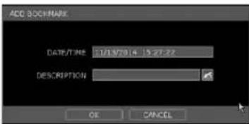
ADD BOOKMARK
Add a bookmark with a description of the currently displayed image.
Enter a description and click OK to save.
INSTANT PLAYBACK
Select from the time options (1 second to 5 minutes) to instantly switch to Playback Mode.
SEARCH
Search recorded video using the calendar, date/time, first and last data, system log, event log, transaction verification and bookmarks. (Please refer to "3.8. Search Recorded Image" for details.)
SMART SEARCH
Search recorded video in preview search or advanced preview search modes. See 3.9 Smart Search for more information.
SPECIAL CAM SEARCH
Search for a special camera log for video analytics. (See 3.10 Special Cam Search for more information.)
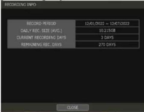
RECORDING INFO
Check the recording status of the NVR, such as Recording Period, Daily Recording Size (Average), Recording Days and Remaining Recording Days.
SYSTEM STATUS
See the system status, network condition, the number of clients currently connected to the NVR, PoE camera connection, etc. A green line means the camera connection is live and working.
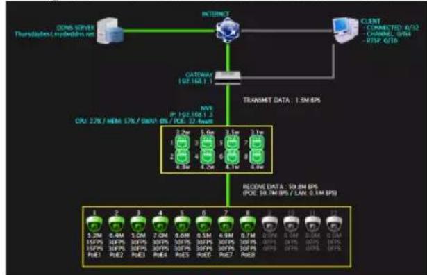
flowchart
graph TD
    A["COM SERVER Thunderbird hybrid network"] --> B["INTERNET"]
    B --> C["CLIENT CONNECTED 8/32 CHANNEL 3/84 RSP 6/10"]
    B --> D["TRANSMET DATA: 1.2M EPS"]
    D --> E["Receive Data: 50.8M EPS (PCE: 50.7M EPS / LAN: 5.1M EPS)"]
    E --> F["1 5.2M 15%PS 15%PS 15%PS PUE PUE2 PUE2 PUE3"]
    E --> G["2 0.4M 20%PS 20%PS 20%PS PUE PUE PUE4"]
    E --> H["3 1.2M 30%PS 30%PS 30%PS PUE PUE PUE5"]
    E --> I["4 0.4M 40%PS 40%PS 40%PS PUE PUE6"]
    E --> J["5 0.5M 50%PS 50%PS 50%PS PUE PUE7"]
    E --> K["6 0.9M 60%PS 60%PS 60%PS PUE8"]
    E --> L["7 0.7M 0.7PM UIPS UIPS UIPS UIPS UIPS"]
    E --> M["8 1.1M 1.1PM UIPS UIPS UIPS UIPS UIPS"]
    E --> N["9 1.1M 1.1PM UIPS UIPS UIPS UIPS UIPS"]
    E --> O["10 1.1M 1.1PM UIPS UIPS UIPS UIPS UIPS"]
    E --> P["11 1.1M 1.1PM UIPS UIPS UIPS UIPS UIPS"]
    E --> Q["12 0.4M 0.4PM UIPS UIPS UIPS UIPS UIPS UIPS"]
DW
ANALYSIS
Check the system's performance, general conditions and network conditions for each channel or the entire system. You may also check the status of cameras connected directly to the NVR's PoE switch and event status.
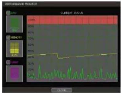
[Performance Monitor]
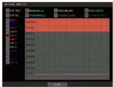
[Network Monitor]
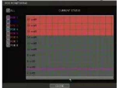
[POE Monitor]
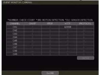
[Event Monitor]
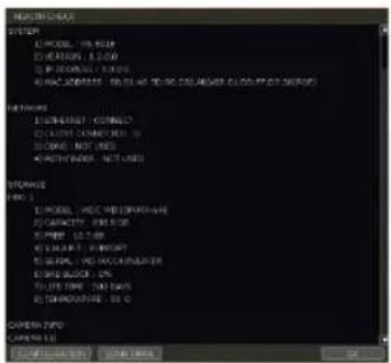
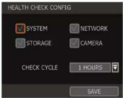
HEALTH CHECK
Display the NVR's system, network, camera, and HDD information as text. Select what information to display in health checks and set up the check cycle interval of how frequently the checks will occur.
MENU
Open the main menu setup screen.
3.6 PTZ Operation
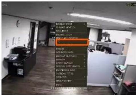
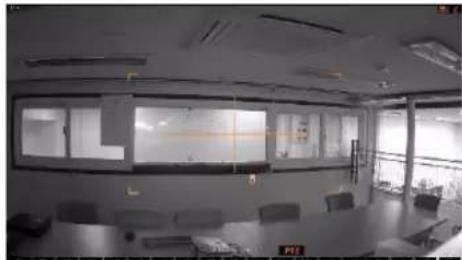
To operate a PTZ camera, the channel connected to a PTZ camera should be in full-screen mode. To activate PTZ control, right-click and select "PTZ" in the pop-up menu. When in PTZ mode, PTZ will appear on the right-button corner of the screen.
PTZ Control
In PTZ mode, the user can control the PTZ camera using the USB mouse. While pressing the left button, drag the mouse cursor up/down or left/right to move the camera's pan/tilt position. The further away from the center the mouse's cursor moves, the faster the PTZ camera will move.
To move the camera to a preset position, click the preset position number at the bottom of the screen to move the camera accordingly. The presets must be set before selection.
natural_image
Interior view of a modern meeting room with large windows and seating (no visible text or signage)Note Full PTZ functions are available by using the USB mouse or keyboard controller. The availability of functions depends on the camera's ONVIF integration. Consult the camera's manual for more information.
ZOOM/FOCUS
If the mode is set to "Zoom", move zoom-in/out by rolling the wheel of the mouse. If the mode is set to "Focus", the camera's focus can be controlled by rolling the wheel of the mouse.
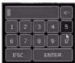
PRESET
When the preset menu pops up, select the preset number and click "Enter" to move to the corresponding preset position. The maximum Preset numbers supported is 255.
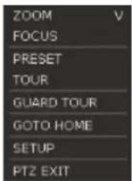
TOUR
Enable the TOUR function. When 'TOUR' is on, the camera will move to preset positions in order. To turn the tour off, right-click on the screen and select 'Tour'.
GUARD TOUR
When enabled, the camera will automatically switch positions according to the sequence of presets set in the GUARD TOUR settings. (See "4.2.3 PTZ" for more information.)
Caution Users can set an interval for each preset position. Some presets might be skipped in cases where a camera cannot mechanically move or cannot control focus within the interval time.
GOTO HOME
The camera moves to the original home position that is saved in the PTZ camera's settings.
SETUP
Go to the PTZ setup menu (Please refer to "4.2.3. PTZ").
PTZ EXIT
Close PTZ control mode.
3.7 Playback Recorded Images
To playback a recorded image, click the Playback icon (TC) in the menu bar. When the NVR transitions to Playback Mode, it will automatically playback the latest recording image.
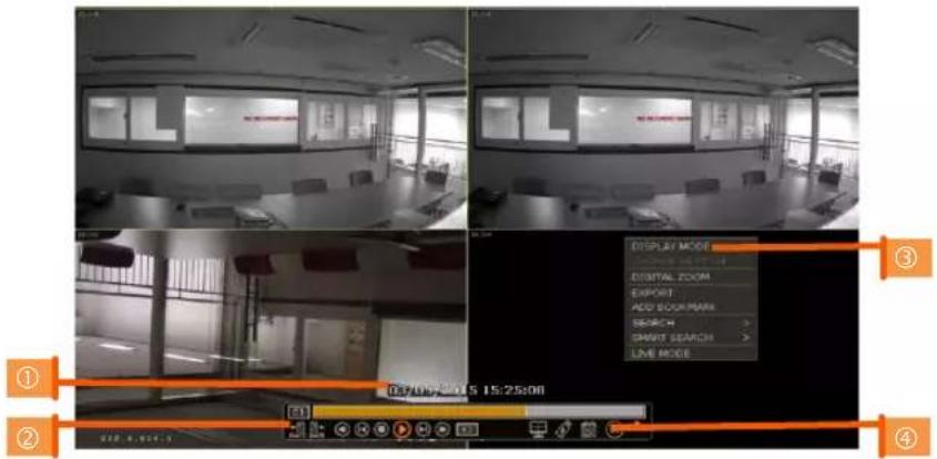
Date/Time (1)
Shows the date & time of the image that is being displayed.
Toolbar (2)
Contains playback controls, recorded data check, screen mode, etc. (See "1.3.4. Toolbar in Playback Mode" for more information.)
Pop-up Menu (3)
• Display Mode: Change display mode (1, 4, 9, 16 screen mode)
• Change Next CH: Change to the next playback channel.
• Digital zoom: Enable or disable digital zoom (available in a single-channel view).
• Backup: Open the backup window.
- Add Bookmark: Add a bookmark to the current image.
- Search: Search recorded data by various conditions (Please refer to "3.8 Search Recorded Image" for detail.)
- Smart Search: Search recorded data with Preview search and advanced preview search. (Please refer to "3.9 Smart Search" for detail)
• Live Mode: Go to Live Mode.
Exit Playback Mode (4)
Clicking the Exit icon ✗ in the menu bar will return you to the live view.
3.8 Search Recorded Video
Search recorded video by date and time, first and last data, events, bookmarks, etc.
To enter the search options menu:
- In Playback Mode, right-click to enter the popup menu and select the search menu.
- In Live Mode, press the Search button in the Toolbar at the bottom of the screen.
- Select the preferred search type.
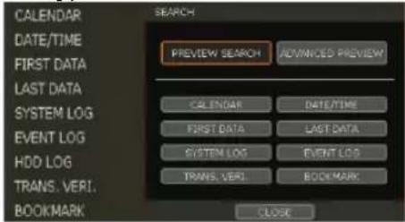
3.8.1. Calendar Search
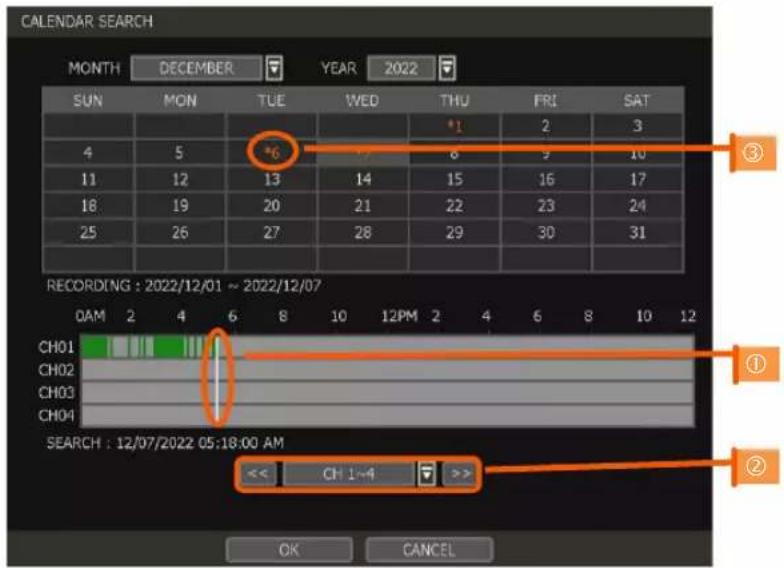
To search for data for a specific date and time, use Calendar Search to select the date and time of the footage.
Move the white-vertical line (①) to the time you want to search.
The colors of the time bar represent the different recording modes. See "4.4.2" for more information. The time bar displays four channels at a time. To check the next 4 channels, change the group at the bottom of the window (②).
The asterisk “*” mark on dates (③) indicates days with recorded videos available.
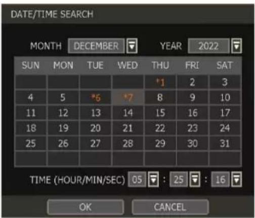
3.8.2. Search Date/Time
Enter the desired date and time on the calendar screen.
Select the desired date from the calendar and use the drop-down to select the desired day/month/year and time category for the search.
Days with recorded data will be highlighted in orange with an asterisk (*) next to them.
3.8.3. First Data
Go to the first screen of the archived recorded video. This is the start of the oldest video recorded. First Data will be overwritten as the NVR records depending on the HDD settings. (For more information see Section 4.1.4 HDD).
3.8.4. Last Data
Go to the last screen of the recorded video. This is the most recent video recorded.
3.8.5. System Log
Find system log information such as System, Setup, or network events.
![SYSTEM LOG 07/13/2019 ~ 07/17/2019 SEARCH ALL SYSTEM SETUP NETWORK DATE 07/13/2019 1/1 NO TIME USER EVENT 1 06:12:00 PM Network Link Down [eth0] 2 05:54:36 PM admin Start system setup 3 05:53:53 PM Camera add (CH:1)[10.0.0.1] 4 05:53:13 PM admin End system setup 5 05:44:03 PM admin Start system setup 6 05:38:32 PM admin User login 7 05:38:19 PM admin User logout 8 05:38:15 PM admin End system setup 9 05:38:14 PM admin Start system setup 10 05:38:11 PM admin User login Network Link Down [eth0] SCAN EXPORT CLOSE](/content/2026/05/1062179/images/bf864d1f58228ce52fecc2b49dba0988c4e0bd7b0d1ca17b16b8f13db0636428.jpg)
- Select a date to search.
- Select log type to search. Users can search for individual events or all at once.
- Click [SEARCH] to show the search results in the list.
- Click [EXPORT] to copy the list to an external device such as a USB flash drive as a ".csv" file. Once the export is completed, the user can find a folder that is labeled with the site
name. A "system.log" file with the exported log can be found stored in the site name folder.
3.8.6. Event Log
Find events such as sensor activation, motion detection, video loss, HDD full, or keyword.
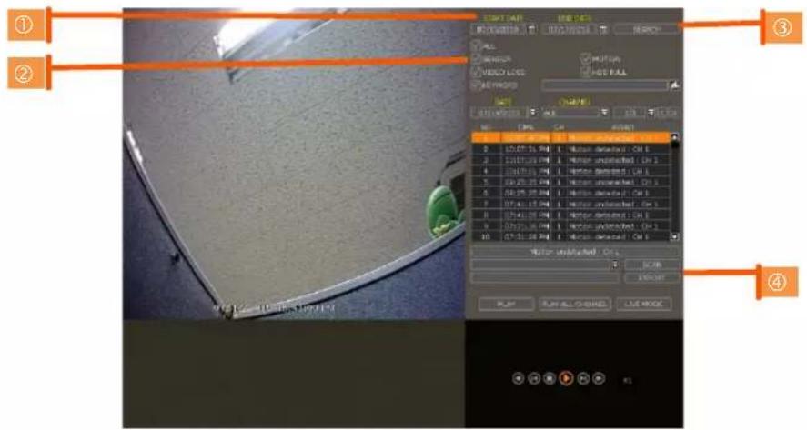
- Select a date to search.
- Select log type to search. Users can search for individual events or all at once.
- Click [SEARCH] to show the search results in the list.
- Click [EXPORT] to copy the list to an external device such as a USB flash drive as a ".csv" file.
Note
Up to 50 recorded events will be shown per page. Click the arrow buttons (◀) to search the log records on another page.
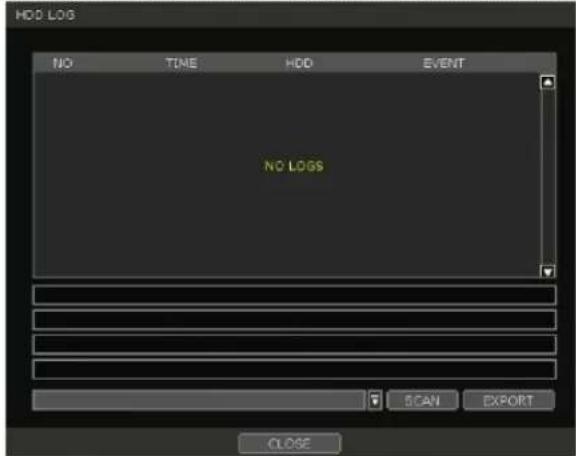
3.8.7. HDD Log
Users can search for HDD logs such as mount failure and record failure.
If there is no problem with HDD, there is no log.
Click [EXPORT] to copy the list to an external device such as a USB flash drive as a ".csv" file.
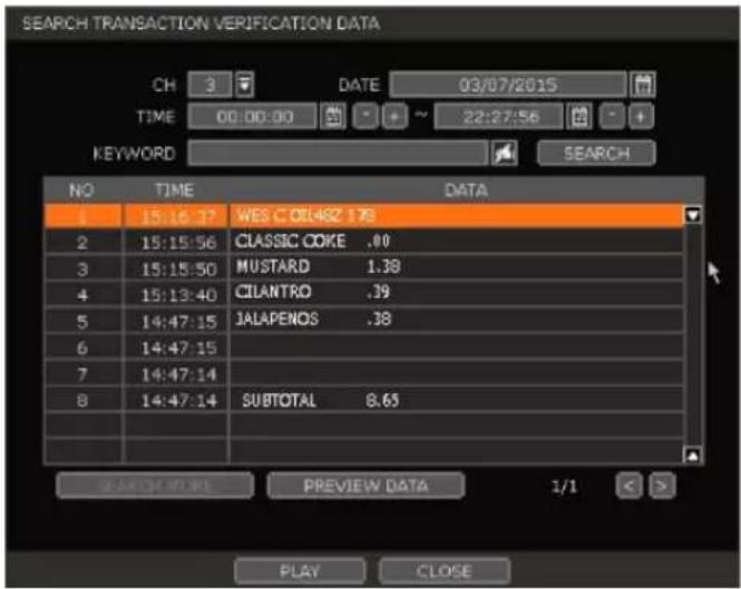
3.8.8. Transaction Verification
Search text from a Transaction Verification™ integration such as a POS device. Input the search information (channel #, date, time & keyword) and then click [SEARCH] to view search results. Enter a keyword to filter the results. Click [PLAY] to go to playback video and transaction data.
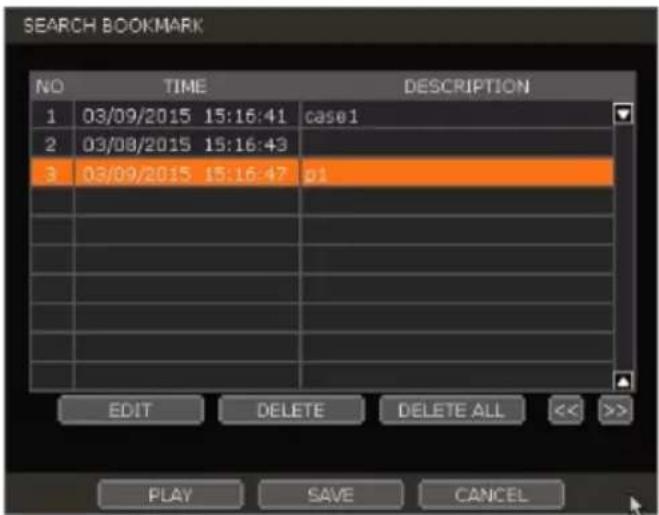
3.8.9. Bookmark
Bookmark search allows you to check, modify and delete bookmarks. Select a bookmark from the search results list and [PLAY] to display the corresponding video image.
3.9 Smart Search
Users can search recorded video in split-screen mode by the hour or minute units. Smart Search supports two different modes - Preview Search and Advanced Preview Search.
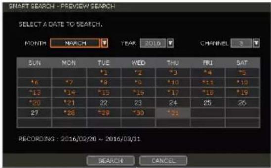
3.9.1. Preview Search
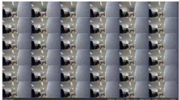
Preview search breaks down a day's worth of recorded video for a camera into 12 still images, one for each hour. You can then "zoom" into the hour to display images for every minute of that hour. To use this search: "
- Right-click on the selected channel and go to Smart Search > Preview Search
- Select the date you wish to search for. Days with recorded video will appear in orange.
- Click Search. The NVR will display 24 preview images (1-hour unit) of the channel on that day.
- Double-click on a specific image or press the minute button to display 60 screen images (1-minute unit) by the minute.
Users can easily search substantial amounts of video for specific events with this preview search, allowing you to playback the recorded image of that moment. The number of thumbnail images and the size of each image can be increased/decreased and the maximum no. is 196(14 x 14), depending on the resolution. In the preview search mode, the user can change the search date, and the display unit (time/minute) and go to Playback Mode directly by selecting a preview image.
natural_image
Grid of identical grayscale images showing a vehicle in various positions (no text or symbols visible)3.9.2. Advanced Preview Search
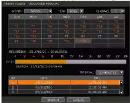
Advanced Preview Search allows you to search a camera's data across multiple days, checking for abnormalities or events at a specific time of the day. To use the Advanced Preview Search:
- Right-click on the selected channel and go to Smart Search > Advanced Preview Search.
- Select the start and end dates you wish to search for. Days with recorded video will appear in orange.
- Select the time interval you wish to search for. The interval can be set from 1 minute to 1 day. Once the interval is selected, set the time of the search. For example, if 1 day is selected, select the time of the day you want to search (e.g., every day at 5 PM).
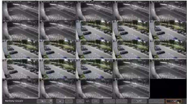
- Press Search. The NVR will playback the recorded image of the selected channel with the selected interval on the multiple screen mode, simultaneously.
natural_image
Grid of 16 grayscale surveillance camera feeds showing outdoor vehicles on a road (no visible text or symbols)3.10 Special Camera Search
3.10.1. Video Analytics
Search video analytics log for events such as object removal, scene change, video blur, video case, line crossing, intrusion, crowd density, people intrusion, people counting and face detection.
Note
To view the special camera search, users must be in single-channel view mode and the camera must support video analytic capabilities.
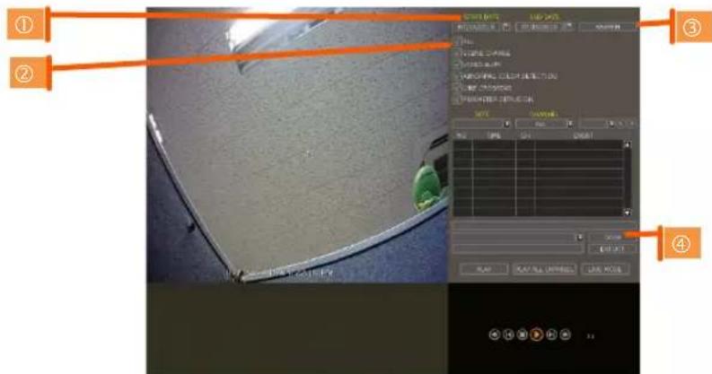
- Select a date to search.
- Select the log type to search. Search individual events or all events.
- Click [SEARCH] to show the search results in the list.
- Click [EXPORT] to copy the list to an external device such as a USB flash drive as a ".csv" file.
3.11 DST Setting and Image Playback
Daylight Saving Time (DST) starts at 2:00 AM local time on the 2nd Sunday of March and ends at 2:00 AM DST on the 1st Sunday of November. During DST, the NVR's clock will be adjusted according to the regional time zone. The NVR's time will shift one hour after DST starts and restore the time clock to normal after DST ends.
3.11.1. DST Setting
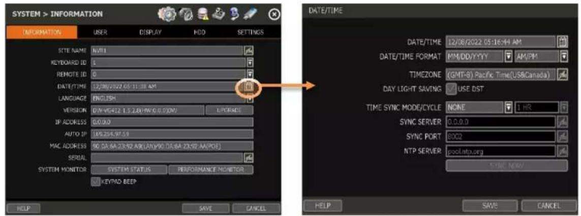
To enable DST on the NVR, go to SYSTEM > INFORMATION and click "DATE/TIME". Select "USE DST" to apply the DST time change. (Select the proper Time Zone to activate DST)
3.11.2. DST Image Playback
When there is overlapped data due to DST, the overlapping hour will appear blue in the search bar during playback.

To play back data from the overlapped hour, select a time in the Intelli-search bar. A "Data Selection" message will appear. Select whether to play DST data or non-DST data.
3.12 MEGApix® IVA™ Analytics
3.12.1. IVA Settings
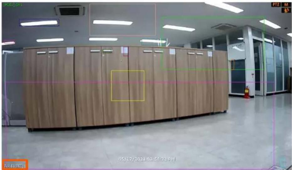
When a MEGApix IVA or IVA+ IP camera is connected to the NVR, the system will display [IVA EVENT] at the bottom of the screen. The camera's preview will include the existing rules' zones and when an IVA event occurs, an event notification icon will appear on the top right of the camera's display.
(*IVA rules can be created and managed from the camera's Web Client, accessible through a web browser. To create, edit or delete IVA rules, please refer to the IVA camera user manual.)
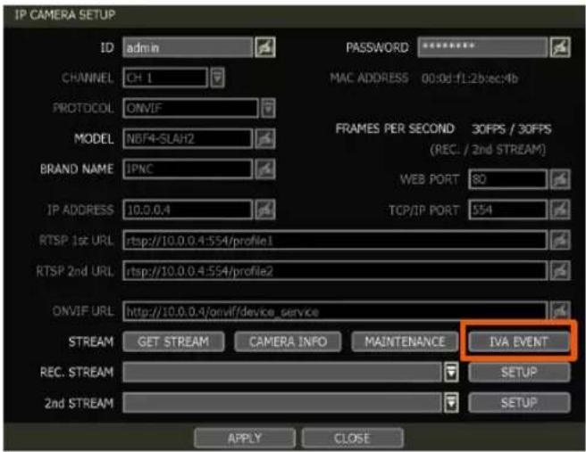
MEGApix IVA camera settings are enabled in [IP CAMERA SETUP] - [IVA EVENT]. Click on the IVA EVENT button to enable the camera as a MEGApix IVA camera and select the appropriate OSD settings.
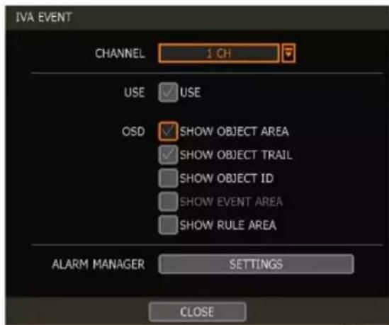
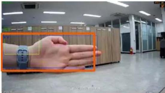
• SHOW OBJECT AREA: This shows the area of a detected object.
NOTE: To enable the SHOW EVENT AREA, this option must be disabled.
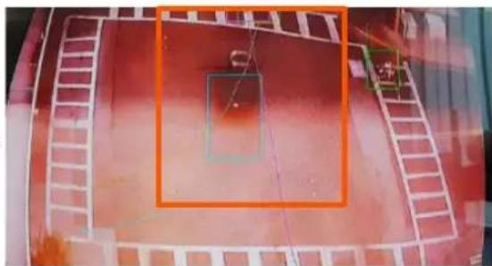
• SHOW OBJECT TRAIL: This shows the trail when a detected object is moving.
natural_image
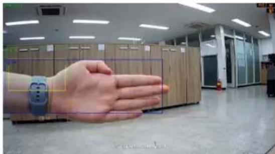
Exterior view of a red brick building with a large orange square overlay and a small green bracket (no visible text or symbols)• SHOW OBJECTED ID: This shows the ID of a detected object.
natural_image
Interior view of a modern office with a hand in the foreground and server racks in the background (no visible text or symbols)- SHOW EVENT AREA: When checked, the event area is displayed only when an event occurs. To use this option, SHOW OBJECT AREA must be disabled.
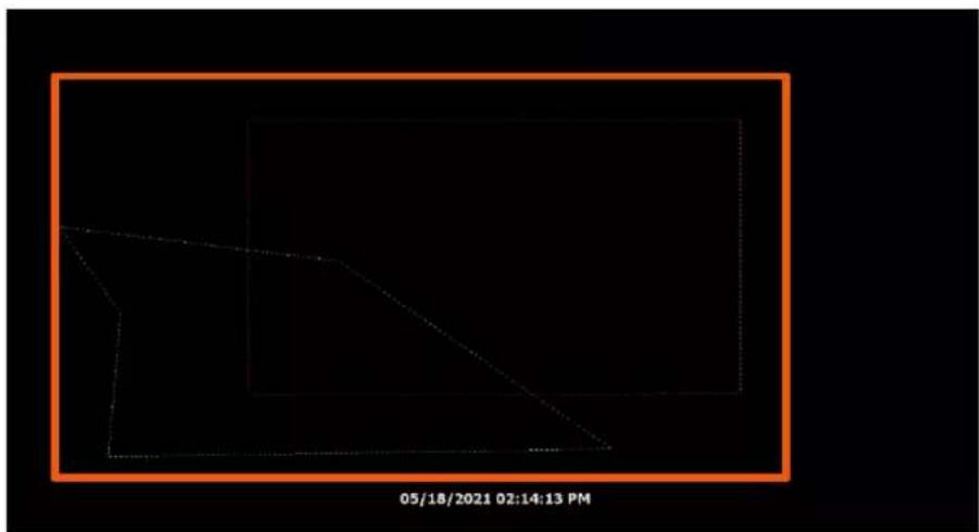
- SHOW RULE AREA: This shows the 'RULE' area. (Refer to the camera's manual for the RULE setting.)
natural_image
Pure geometric line drawing with no text, numbers, or symbolsDW
3.12.2. ALARM MANAGER
Set an IVA EVENT ALARM
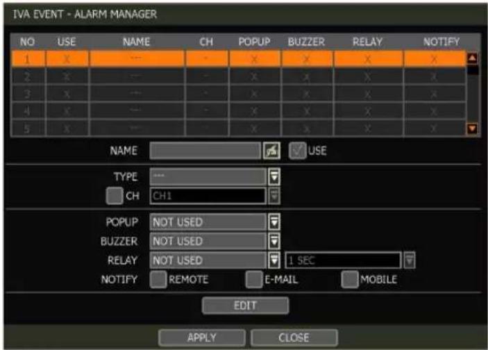
If the user checks 'USE', the settings window will be activated and the user can set an event alarm name, type, and notification type (pop-up, buzzer, relay, etc.).
• Name: Create a name for the IVA event alarm.
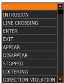
- Type: Select the alarm event type. The alarm type is directly related to the analytic type triggered by IVA analytics.
- CH: Enable 'CH' and select the channel of the camera.
- Popup/Buzzer/Relay: Select how the NVR will respond when the alert is triggered.
o Popup: A pop-up window will display.
- Buzzer: An alert tone will emit from the NVR.
- Relay: An external relay (RS-485 connection) will trigger.
- Notify: Select the notification type that will be sent. (See Section 4.5.3 Notification for more information.)
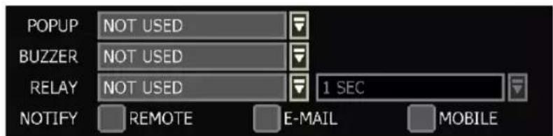
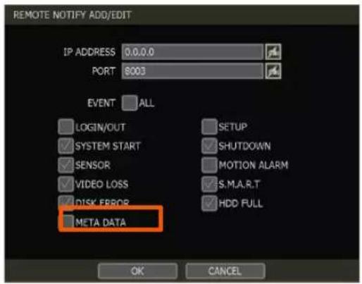
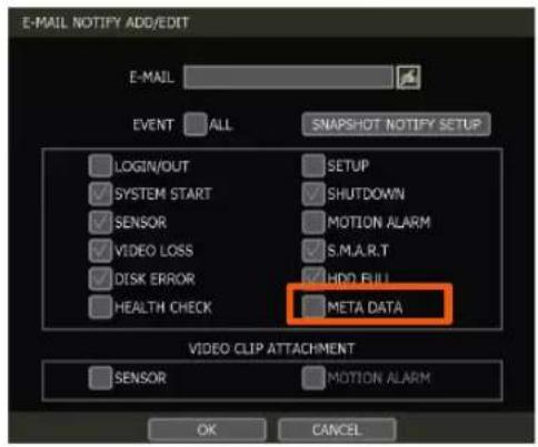
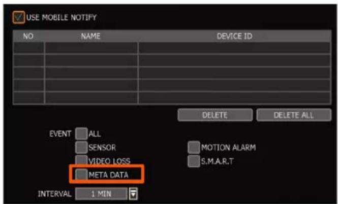
※ To set REMOTE / EMAIL / MOBILE NOTIFY, the user must check 'META DATA'.
3.12.3. MEGApix IVA EVENT SEARCH
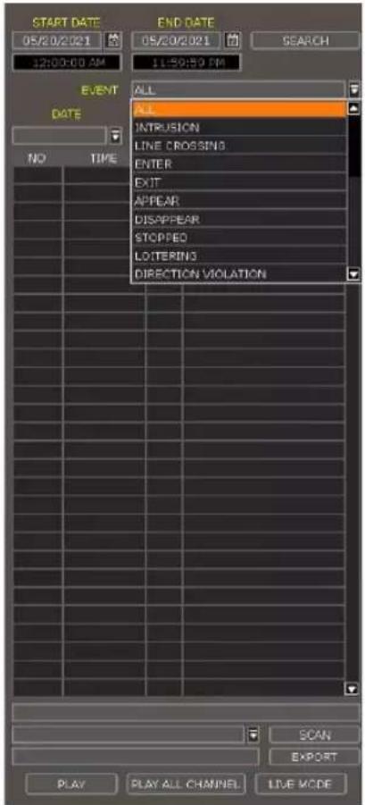
To search for IVA analytics events, go to the popup menu > SPECIAL CAM SEARCH > IVA EVENT. Select IVA EVENT from the drop-down list options. Use the date and type filters to narrow down search results.
Double-click the event from the event results list to view the video associated with the event.
| NO | TIME | CH | EVENT |
| 1 | 11:07:56 | 2 | APPEAR:START:ID=5627... |
| 2 | 11:07:56 | 2 | APPEAR:START:ID=5627... |
| 3 | 11:07:56 | 2 | APPEAR:START:ID=5627... |
| 4 | 11:07:56 | APPEAR:START:ID=5627... | |
| 5 | 11:07:56 | 2 | APPEAR:START:ID=5627... |
| 6 | 11:07:56 | 2 | APPEAR:START:ID=5627... |
| 7 | 11:07:56 | 2 | APPEAR:START:ID=5627... |
| 8 | 11:07:56 | 2 | APPEAR:START:ID=5627... |
| 9 | 11:07:53 | 2 | APPEAR:START:ID=5627... |
4.NVR Settings Menu
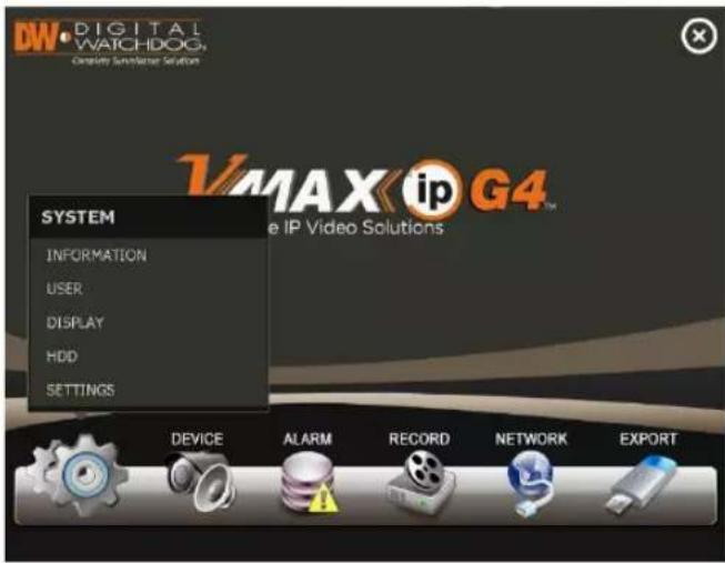
The general setting structure consists of "System", "Device", "Event", "Record", "Network" and "Backup". Each Setup menu consists of sub-menus and additional categories.
To access the setup menu, click the the "Menu".

button in the menu bar or right-click anywhere and select
| Main Classification | Sub Classification |
| SYSTEM | INFORMATION |
| USER | |
| DISPLAY | |
| HDD | |
| SETTINGS | |
| DEVICE | CAMERA |
| AUDIO | |
| PTZ | |
| TRANS. VERI. | |
| KEYBOARD | |
| ALARM | SENSOR |
| CAMERA ALARM | |
| EXTRA ALARM | |
| RECORD | CAMERA MANAGEMENT |
| RECORDING SCHEDULE | |
| QUICK SETUP | |
| NETWORK | NETWORK |
| DDNS | |
| NOTIFICATION | |
| MOBILE NOTIFY | |
| PATHFINDER | |
| EXPORT | EXPORT |
4.1 System
4.1.1. Information
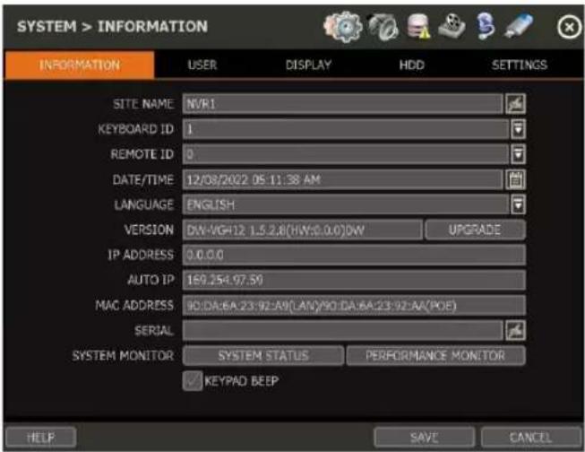
SITE NAME
Enter a site name to differentiate the NVR from other sites if there is more than one NVR present.
KEYBOARD ID
Set up the SITE ID to match the ID settings of a keyboard controller. The keyboard model and BUAD RATE must be set up in "MENU > DEVICE > KEYBOARD" (See "4.2.5 Keyboard").
REMOTE ID
Not supported
DATE/TIME
Using the available options, the administrator can manually adjust the system date and time, select the time and the date format, and select the appropriate time zone. If applicable, check the 'USE DST' box to use daylight savings time.
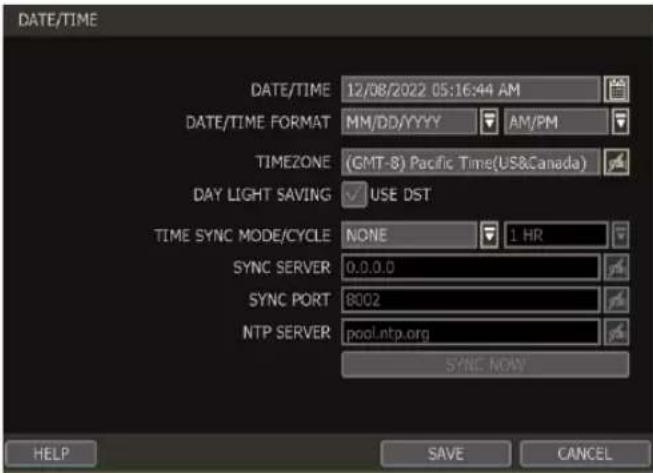
There are three types of time sync modes.
- Server Mode: The operating NVR is set as a Time Sync Server, which can synchronize the time settings of other NVR(s) that are connected to it over the same network.
- Client Mode: Input the IP address of a designated NVR or a PC using Remote Software (C3 CMS) that is serving as a Time Sync Server in "SYNC SERVER". The NVR's time clock will be
synchronized with the designated server by updating at regular time intervals as set in the "TIME SYNC CYCLE" setting.
- NTP Server Mode: "pool.ntp.org" is the recommended NTP Server. To activate, set the TIME ZONE of your local area then click [SYNC NOW].
• GPS Mode: Connect USB type GPS device and click [SYNC NOW]
For the DST settings, please refer to "3.11 DST Time Setting".
LANGUAGE
Select the display language for the system.
VERSION
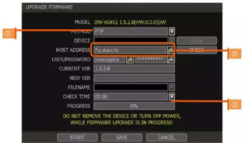
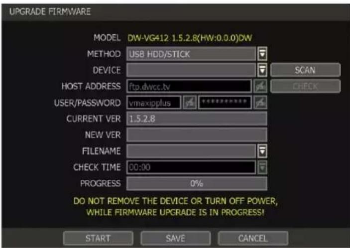
View the NVR's current firmware version and update it to a newer version via USB Memory Stick or FTP server.
| Caution | Do not click CANCEL during firmware upgrade. It may cause considerable damage to the system.Settings may be changed to factory default. It is recommended to check the settings and operating conditions of the NVR after the firmware upgrade. |
Upgrading system using USB memory stick:
- Insert a USB drive with the firmware file formatted by FAT/FAT32 in any USB port of the NVR (compatible with USB 2.0).
- Select 'USB' from the Method drop-down options and press the 'Scan' button.
- Once the system detects the USB drive, it will display the firmware file under 'CURRENT VER' and the 'NEW VER'.
- Click START to begin the upgrade process.
Upgrading system via FTP server:
- Select FTP in the drop-down options under 'Method'.
- Enter the FTP's address: FTP.dwcc.tv and enter the username and password (these should be filled out automatically). Username: vmaxipplus, password: vmaxipplus.
NOTE The FTP server address is subject to change without a prior notice - Enter Check Time. The system will automatically check the FTP server for newer firmware every day at set hours.
- Click the [OK] button to proceed with the automatic firmware upgrade. After completion, the system will reboot.
- Click 'Check' to allow the NVR to connect to the FTP server and check the latest Firmware version. If new firmware is available, the NVR will ask you whether you want to upgrade it or not.
- Click 'OK' to confirm and click 'START' to start upgrading.
To set up the NVR to check for new firmware automatically:
- Select FTP from the METHOD drop-down options.
- Make sure the FTP information is entered correctly (see the section above).
- Enter your convenient time at CHECK TIME and then click the [SAVE] button.
IP ADDRESS
Shows the NVR's current IP Address. It can be set at 'MENU>NETWORK>NETWORK'.
AUTO IP
Shows AUTO IP Address of the NVR.
MAC ADDRESS
Shows the unique identity number for the NVR.
SERIAL
Input or edit the unit's serial number to provide additional identification information.
SYSTEM / PERFORMANCE MONITOR
Monitor the system's performance and condition.
KEYPAD BEEP
Users can turn on or off the beeping sound of the keypad.
4.1.2.User
The ADMIN user has full authority for system settings and can change the system password or add/delete users and assign different permission levels to them.
Note The maximum number of users including an administrator is 16.
User Management
Admin users can control authorization for each function. This authorization is applied when the user connects to the NVR from remote software as well.
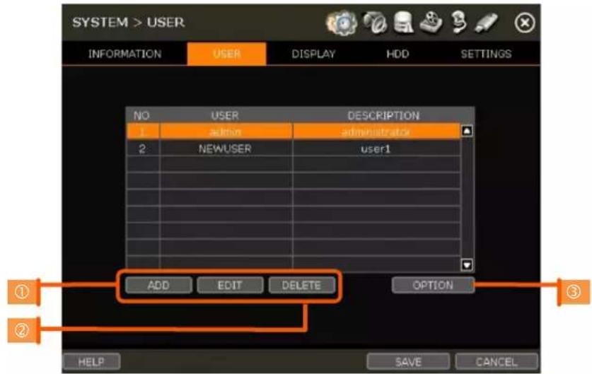
1. Add User
a. Click [ADD].
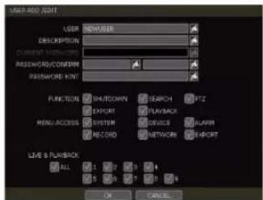
b. In the new setup window, set the new user's ID, description, password and password hint.
c. Select which functions and menu options the user will have access to by checking the box next to the corresponding functions.
d. In Live and Playback Mode, only the selected channels are visible to the user.
e. To change the setting, select the user and click [Edit].
2. Delete User
a. Select a user in the list by highlighting their name and clicking [Delete].
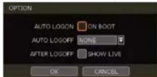
3. Option
a. If Auto Logon "On Boot" is enabled, the NVR will not request ID and password after power-up.
OPTION
b. If "Auto Logoff" is enabled, the NVR will log off the current user after the set time of inactivity.
c. If "show live" is checked, the live image will be shown after logging off.
Setting Authorized Level at the Remote Software (C3 CMS)
The level of authority for the user is linked between the NVR and remote software. If a user has been restricted in the NVR, those restrictions will also be applied when operating the remote software.
4.1.3. Display
Set the Sequence dwell time, Display Resolution, OSD display options and spot-out channel.
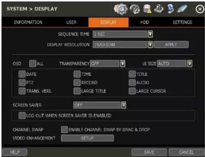
SEQUENCE TIME
Set the dwell time for the channel sequence display. Camera channels will rotate during Sequence according to this setting.
DISPLAY RESOLUTION
The system supports the following kinds of resolutions: 800x600, 1024x768, 1280x1024, 1920x1080 and 3840x1260. Set the proper resolution output per the connected monitor resolution. DO NOT set the display resolution to be higher than what the connected display monitor can support.
OSD
Select what information will appear and overlay the channel displays by checking the corresponding boxes.
SCREEN SAVER
The Screen Saver feature protects the display monitor's screen and reduces resource use of the NVR by turning the display off after a set time of inactivity. Set the screen saver's waiting time for when the monitor will automatically turn off. Set in between 1 minute and 180 minutes. For increased security, select to log off the current user when the screen saver activates.
CHANNEL SWAP
Check for swapping the channel by drag and drop.
VIDEO ENHANCEMENT
Set the display details such as brightness, contrast, sharpness and etc. (*This function may not be supported depending on the NVR model.)
4.1.4. HDD
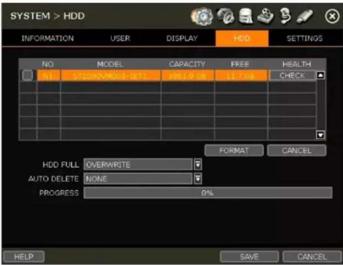
HDD FULL
When an HDD is full, select whether to "Overwrite" or "Stop recording".
• Overwrite: Record new data over the oldest data in the drive.
- Stop record: Stop all NVR recording when the HDD is full.
HDD CHECK
Click [CHECK] next to each HDD to open the health check window. See full information for each HDD such as model name, port, serial no, capacity, bad sector ratio, lifetime (used time) and temperature.
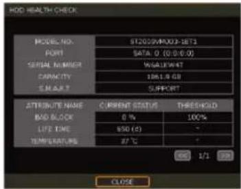
Caution
WARNING MESSAGE
To achieve high-level system stability, a warning message of elevated temperature will display when the temperature inside the NVR exceeds the optimum range. This problem may be caused by the malfunction of ventilation fans or environmental factors. Inspect to see if the cooling fan is properly working or if the environmental temperature around the system is too hot.
HDD FORMAT
When a new HDD is installed or if there is a problem with the HDD, formatting the HDD is recommended. All data on the HDD will be deleted during an HDD format.
If system resources are occupied such as during a network connection while the HDD format is in process, the formatting may fail. Reboot the system to release system resources and then try to format again.
Check the box next to the HDD name to select it. Press the "format" button to format the HDD.
AUTO DELETE
Set the period when the HDD will automatically delete all recorded data. Select from None (default) up to 366 days.
Note
1) It may take a few minutes to format an HDD.
2) When the format is done, ALL DATA in the HDD will be deleted.
3) The system always reserves some space in each built-in HDD to effectively utilize archiving memory.
4.1.5. System Settings
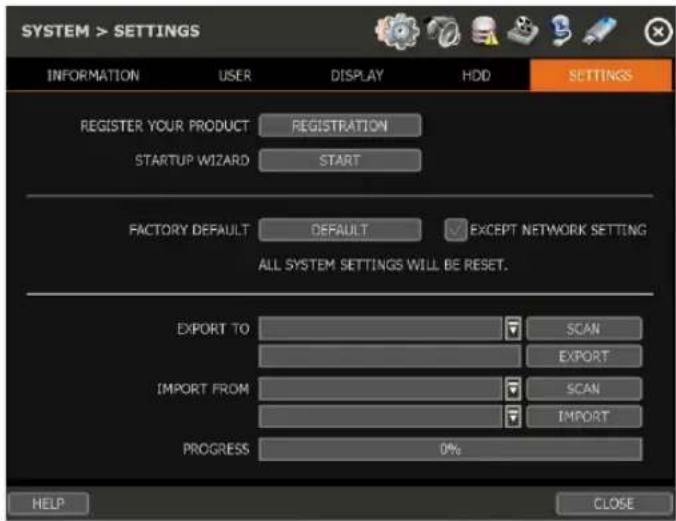
STARTUP WIZARD
Users can register their information on the DW server. Registering the product can assist DW personnel when seeking product support and repair.
STARTUP WIZARD
Click [START] to prompt the startup wizard.
FACTORY DEFAULT
Reset the system to its factory configuration. All the configurations will be deleted, and the system settings will return to its original factory default. The recorded video will not be deleted.
EXPORT/IMPORT
Save the system settings from this NVR or copy them to another NVR.
- Export: Copy the settings of this system to a USB memory device.
- Import: apply settings from another NVR via USB memory device.
| NOTE | If uploading exported settings to a different NVR, the F/W version of the new NVR must be the same version as the sourced NVR. |
4.2 Device
4.2.1. Camera
Set each camera's title, covert channel settings, privacy masks and general camera adjustments.
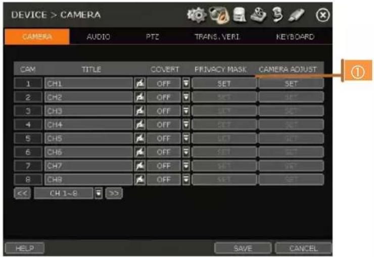
Note To be able to set up these functions from the NVR and affect camera settings, the cameras must support ONVIF. If the camera is ONVIF but the settings were not integrated via ONVIF, you will have to set up the camera's settings from the camera's menu.
TITLE
Designate a name for each channel. The name will appear both in the NVR and remote software.
COVERT
"Covert," also called 'hidden camera', hides camera display and playback as if there were no camera recording for non-admin users. Covert settings apply to both Live and Playback viewing in both the NVR and remote software.
Note Only the ADMIN user can set up a covert menu. Non-admin users will see a blank channel.
PRIVACY MASK
Hide specific areas in the camera's Field of View (FoV) in live and Playback Mode. Please check that your camera supports this feature.
- Click [SET] beside the desired channel to configure a privacy mask.
- Use the popup menu on the bottom right to select where to place the privacy mask, assign a color, and index number to the mask. Click 'Save' to save the changes and 'Exit' to return to the main setup page.
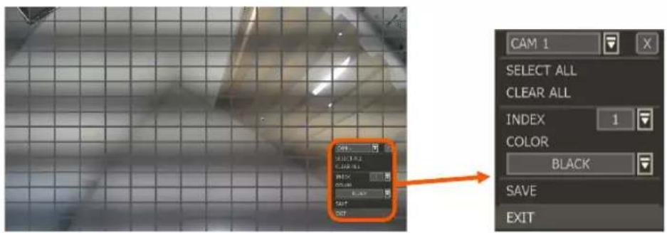
DW
CAMERA ADJUST
Set the camera's brightness, contrast, color, etc.
- Click [SET] in the 'CAMERA ADJUST' section beside the desired channel.
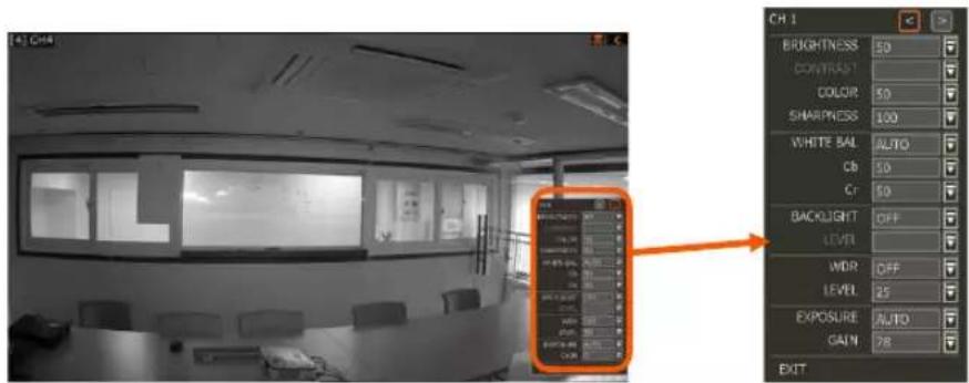
- Adjust the applicable options using the drop-down menu options.
- Click 'Save' to save the changes.
- Switch to the next channel using the arrow buttons (◀)
- Changes will apply to the camera's view automatically.
- [Apply All] makes all channels have the same value.
- Click [EXIT] to exit.
4.2.2. Audio (Live and Recording)
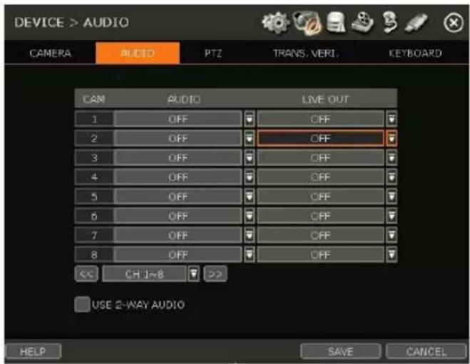
Select an audio input and output and match it to a specific channel. The number of audio channels may differ depending on the NVR model. When enabled, the channel will start recording video with the associated audio channel, allowing users to playback recorded video with audio.
- AUDIO: Activate and designate camera channels for audio input capture. To hear audio, an audio output device must be connected to the NVR or be viewed using the Web Viewer.
- LIVE OUT: Activate and designate camera channels for audio output through a connected speaker. An audio output device must be connected to hear audio from the NVR. Full screen the channel to hear video while viewing in Live Mode.
• USE 2-WAY AUDIO: Enable to allow two-way audio for connected devices.
4.2.3. PTZ
Full control of the PTZ camera is available on this menu. Please refer to the "3.6 PTZ Operation" for more information on operating a PTZ camera.
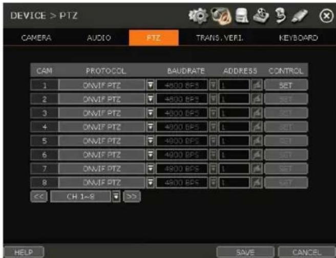
- If the camera is connected to the NVR via ONVIF protocol, make sure ONVIF PTZ is selected in the Protocol field.
- If the camera is connected via RS-485 cables, make sure of serial communication with the PTZ camera through the RS-485 port is set up properly. The Protocol, baud rate and camera address set in the NVR must match the ones set in the camera's setting.
DW
PROTOCOL
Select the proper protocol of the connected PTZ camera. This determines the protocol that the camera and NVR communicate with. This field does not need to be changed if the camera is connected to the NVR over the network via the ONVIF protocol. Default is ONVIF PTZ.
BAUD RATE
Select the baud rate level from 2,400bps up to 57,600bps. This determines the rate that information is transferred between the camera and NVR. This field does not need to be changed if the camera is connected to the NVR over the network via the ONVIF protocol.
ADDRESS
Set the P/T/Z driver address of the connected camera. This determines which camera to send PTZ signals to if connected by RS-485 and should be the same address as that of the PTZ camera. This field does not need to be changed if the camera is connected to the NVR over the network via the ONVIF protocol.
CONTROL (The functions depend on the camera's model and supported features)
When the [SET] button is clicked, the OSD menu of the camera will appear on the monitor. Set the PTZ's speed, preset, tour, auto-pan, etc.
• Direction buttons: move camera up/down & left/right.
- M (depends on the PTZ model): Show/ hide the camera's OSD menu on the NVR monitor. Use the directional arrows to navigate the menu options.
- ZOOM/FOCUS/IRIS: Control IN (+)/OUT (-) for each function. (Depending on the camera's model and supported features).
- Speed: Change the PTZ speed (0\~100). This sets the speed at which the camera will move when controlled from the NVR using the virtual joystick. Save the changes by clicking [SET].
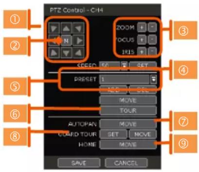
- Preset: Select the PTZ preset position that was created within the PTZ camera itself. Preset position setup must be configured within the camera's web interface.
- ADD: Move the camera's position and zoom to the desired position. Select the preset number using the button. Press [ADD] to save the new preset. (The system supports preset the number of presets from 1 to 255.)
o DEL: delete the preset currently selected.
○ MOVE: Enter a present number and press [Move] to move the camera to the preset
position of that number.
- TOUR: Set the camera to move between preset positions in order. The camera will keep running the tour until it manually is disabled.
○ AUTO-PAN: Set the camera to move 360^ in one direction. The camera will keep running the auto-pan until it manually is disabled.
GUARD-TOUR: Set the camera to move between selected presets in a set order and interval. The camera will keep running the guard tour until it is manually disabled.
- Set: Set the Interval (Sec) and select the preset position. Add to Sequence by clicking the ➤ button. The preset will appear in the Sequence column indicating the preset number and the set interval time.
- Delete: To delete a preset position from the sequence, select the preset in the Sequence column and click the ✕ button.
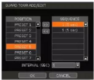
■ MOVE: Start GUARD TOUR.
- HOME: Set the camera to move to an original position memorized by the camera.
In cases where the PTZ camera is directly connected to the rear panel of NVR, the AUX control button (AUX) is shown. Users can control additional settings such as Power, Light, Wiper and Pump, etc.
4.2.4. Transaction Verification Settings
Transaction verification equipment can be connected to NVR through the RS-232 port or LAN.
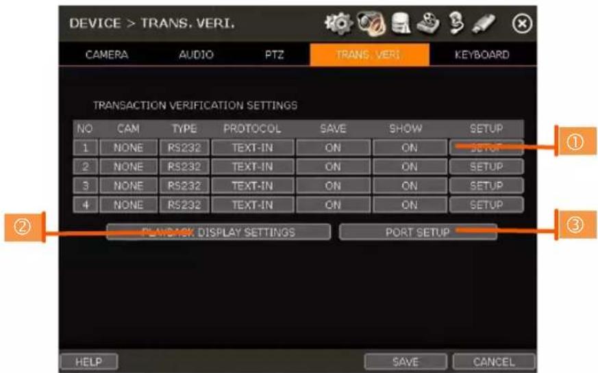
NO
Port Number of the Serial connection (RS-485 terminal block). For example: NO1 = COM1, NO4 = COM4.
CAM
Assign a camera to the Transaction Verification device. The Transaction information will be associated with the assigned camera.
TYPE
Connection type between NVR and Transaction Verification device.
PROTOCOL
The communication protocol between NVR and Transaction Verification device.
SAVE
Enable or disable the NVR to save the transaction data.
SHOW
Enable or disable the NVR to display the transaction data.
SETUP (1)
Transaction Verification Settings
- NO: ID# of Transaction Verification device.
- CAMERA: Select the camera to assign to the Transaction Verification device.
- TYPE: Select COM (RS-232) or TCP/IP (LAN)
- DEVICE IP: Input the IP address of the Transaction Verification device when it is connected through the network.
-
PROTOCOL: Communication protocol between NVR and the Transaction Verification device.
-
TEXT-IN: Receive an ASCII character.
-
SNVR-POS: Manufacturer's protocol.
Contact your Transaction Verification dealer for information.
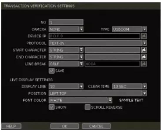
- START CHARACTER: Input the assigned character to start display and save. If there is no input, the system will display and save all data without classification per transaction.
-
END CHARACTER: Input the assigned character to terminate display and save. It must have a START CHARACTER to work correctly.
• LINE BREAK: Set the line change character. (It should be 16 digits HEX Value.) -
[CRLF] / [CR] / [LF]: The character that is used in ASCII-type Transaction Verification. (Please contact the Transaction Verification manufacturer for detail.)
-
[Custom]: It can be used except for the above general character. Only numbers (0\~9) and alphabet (A \~ F) can be used and even numbers should be input. ex) Hexadecimal: 0x0D 0x0A → 0D0A.
- SAVE: Save the transaction verification data.
Live Display Settings
- DISPLAY LINE: Set the number of lines to display on the screen.
- CLEAR TIME: Set the period to display text on the screen. Data will be deleted from the screen if no new data is entered after the set time. If it is set as "O", the data will not be deleted (If there is Start Character and the character is input, current data will be deleted regardless of the Clear Time setting).
- POSITION: Designate the display position of transaction data.
- FONT COLOR: Select the font color which will be displayed on the screen. It will be displayed with the color that is shown on "SAMPLE TEXT"
- SHOW: Select to display transaction data in the Live Mode. Transaction data will overlay the video stream.
- SCROLL REVERSE: Select to change the direction of scrolling. If it is selected, you can scroll from the bottom to the top, the latest data is displayed on the top.
PLAYBACK DISPLAY SETTINGS (2)
Open setup screen for Playback Mode
- DISPLAY LINE: Set the number of lines to display on the screen.
- CLEAR TIME: Set the period to display text on the screen. Data will be deleted from the screen if no new data is entered after the set time. If it is set as "O", the data will not be deleted (If there is Start Character and the character is input, current data will be deleted regardless of the Clear Time setting).
- POSITION: Designate the display position of transaction data.
- FONT COLOR: Select the font color which will be displayed on the screen. It will be displayed with the color that is shown on "SAMPLE TEXT"
- SHOW: Select to display transaction data in the Playback Mode.
- SCROLL REVERSE: Select to change the direction of scrolling. If it is selected, you can scroll from the bottom to the top, the latest data is displayed on the top.
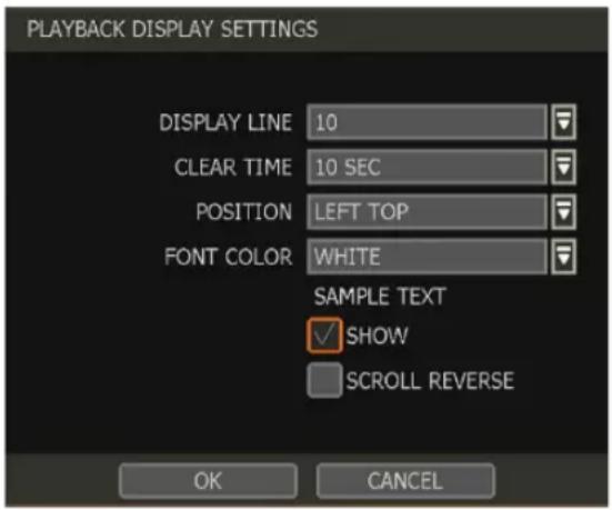
PORT SETUP (3)
Open the setup screen for the communication port.
• TYPE: Set up the type of communication port.
- SERIAL: It is for a 1-to-1 connection between NVR and Transaction Verification device without Serial Mux.
o MUX: It is for a 1-to-Multi connection between NVR and Transaction Verification device
- BAUDRATE: Set BAUDRATE according to the Transaction Verification device.
- PARITY: Set the parity according to the connected device.
- DATA BIT: Set DATABIT according to the connected Transaction Verification device.
- STOP BIT: Set STOPBIT according to the connected Transaction Verification device.
• TCP/IP PORT: Set the TCP/IP Port number.
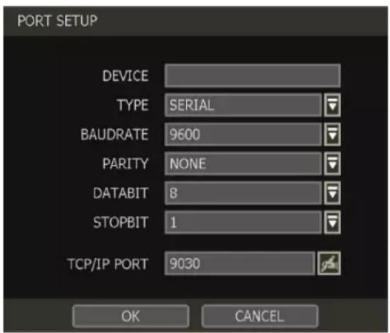
4.2.5. Keyboard
When an external keyboard controller is used, configure the settings to use the keyboard with the NVR. Make sure the Keyboard ID in the SYSTEM> INFORMATION setup page matches the device ID that is set on the keyboard.
• KEYBOARD CONTROLLER: Select the keyboard model.
- BAUDRATE: Select the corresponding baud rate used to communicate with the keyboard. The baud rate must match the one set in the keyboard itself.
- USE KEYBOARD: Enable to allow keyboard control of the NVR. Mouse interaction will still be available.
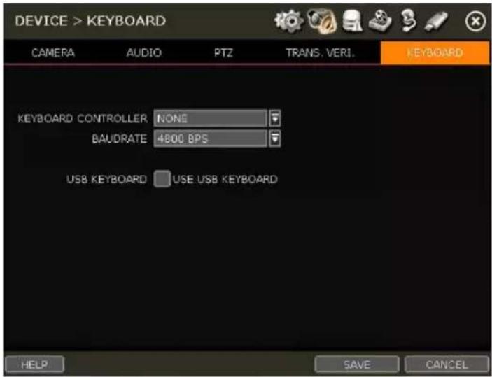
4.3 Alarm
4.3.1. Sensor
Users can install multiple sensors on the system to get the pre & post-alarm recording and intensive recording functions as well.
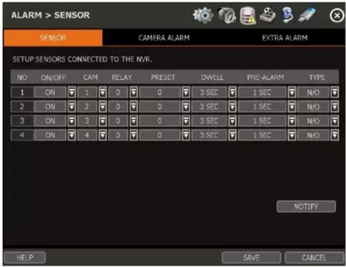
ON/OFF
Turn on or turn off the sensor input.
CAM
Select the associated camera for the alarm.
RELAY
Select the associated alarm output for serial connection (RS-485).
Caution Relay contacts can stand up to 24V/1A. In cases where it is connected to the external circuit which is over 24V/1A, it can cause a problem in the system.
PRESET
Set a PTZ camera to move to a preset position when the sensor is triggered. A PTZ camera must be assigned for the alarm and the preset position must be configured within the camera.
DWELL (Post Alarm)
Set the recording period from when the sensor is activated. During this period, the selected camera will record according to the record-setting. The recording stops and the alarm output is turned off when the set period has passed.
PRE-ALARM
Set a recording period in seconds just before a sensor is activated. Input up to 5 seconds. The pre-alarm recording mode is always “continuous” at the recording speed that the user sets in the “Record” menu. The recording period will run before triggering the alarm.
TYPE
Select the sensor type as N/O (Normal Open) or N/C (Normal Close). The circuit of a N/O sensor type is usually open, and the activation of the sensor occurs at the time of close, and the N/C type works the reverse way.
Note Check the setting of the sensor type (N/O or N/C). It is recommended to use "Dry Contact
Type" while "Wet Contact Type" may cause damage to the system.
NOTIFY
Enable and select for the sensor notification to create a buzzer sound and/or a pop-up warning when triggered.
Note When "Camera pop-up" is enabled, in a multi-screen mode, the system will switch to single-channel mode and automatically when the alarm is triggered.
4.3.2. Camera Alarm
Set up the NVR to start recording when motion is detected. The system can also trigger an alarm signal via the selected sensor-out channel. Motion detection must be enabled and configured within the associated camera for the NVR to detect motion.

ON/OFF
Turn on or turn off the camera alarm. When turned ON, the NVR will trigger an event alarm when motion is detected.
RELAY
Select related output. The NVR will output a signal through the selected relay output port (RS-485).
Caution Relay contacts can bear up to 24V 1A other devices. If it is connected to a power source of more than 24V 1A, the system may have a problem with it.
DWELL
Set sensor operation time between 1 and 15 seconds. The camera alarm will remain active until the assigned dwell time has passed.
PRE-ALARM
Set a recording period in seconds just before motion is detected. Input up to 5 seconds. The pre-alarm recording mode is always “continuous” at the recording speed that the user sets in the “Record” menu.
MOTION AREA
Set the camera's motion area and sensitivity. The area can be selected by clicking on a specific block or dragging the mouse's cursor across the screen to select multiple blocks. Areas where motion detection is activated will appear with a green border. Unselected areas will be shown with a grey border.
- Click [SET] in the 'MOTION AREA' section to set the area.
- Select the motion detection area and click [SAVE] and then [EXIT] to save the changes. Clicking on SELECT ALL will enable motion detection in the entire camera's FoV.
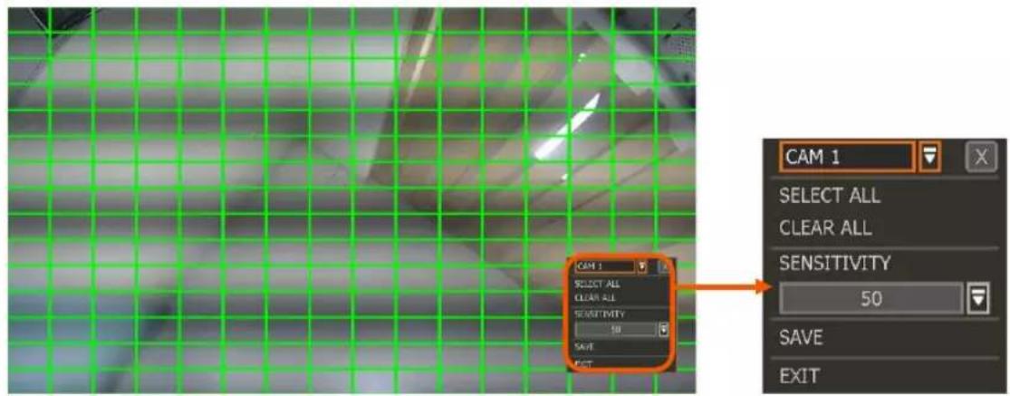
Note Motion detection area and sensitivity should be set, properly, in consideration of the actual motion that happened on the site.
COPY SETTING
To apply the settings to all cameras connected to the NVR, click on the Copy Settings button:
- Select the channel to get the setting from
- Select the property(s) to copy.
- Select the target channel(s) to apply the setting.
- Click [OK] to apply the setting to all the other selected channel(s).
EVENT MONITOR
Show the event number for each camera. It shows check count numbers, motion detection and sensor detection.
NOTIFY
Enable and select for the sensor notification to create a buzzer sound and/or a pop-up warning when triggered.
Note When "Camera pop-up" is enabled, in a multi-screen mode, the system will switch to single-channel mode and automatically when the alarm is triggered.
4.3.3. Extra Alarm
Set up alarms for additional NVR abnormalities such as SMART HDD check, VIDEO LOSS, RECORDING FAILURE and DISK FULL.
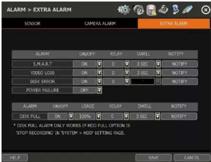
S.M.A.R.T.
Trigger an alarm signal when the HDD is about to be out of operation or is otherwise experiencing drive health issues. Please refer to "4.1.4 HDD" to check the HDD status.
VIDEO LOSS
Trigger an alarm signal when a camera signal is suddenly disconnected.
DISK ERROR
Trigger an alarm signal when the system does not record images due to an error in HDD.
DISK FULL
Trigger an alarm signal when the HDD is occupied with a certain percentage of its capacity. If the user sets HDD FULL as STOP RECORDING and the HDD is occupied with the certain percentage set here, NVR stops recording and the alarm trigger.
Note The extra alarm will appear in the event log only when it is set as "ON".
ON/OFF: Set to 'ON' to enable the alarm type.
RELAY: Select related output. The NVR will output a signal through the selected relay output port (RS-485).
Caution Relay contacts can bear up to 24V 1A other devices. If it is connected to a power source of more than 24V 1A, the system may have a problem with it.
DWELL
Set sensor operation time between 1 and 15 seconds. The camera alarm will remain active until the assigned dwell time has passed.
NOTIFY
Enable and select for the sensor notification to create a buzzer sound and/or a pop-up warning when triggered.
Note When "Camera pop-up" is enabled, in a multi-screen mode, the system will switch to single-channel mode and automatically when the alarm is triggered.
4.4 Record
4.4.1. Camera Management
Users can register/delete/set up cameras by letting the NVR scan and register cameras automatically or manually search and add cameras.
![RECORD > CAMERA MANAGEMENT CAMERA MANAGEMENT RECORDING SCHEDULE QUICK SETUP AUTO CONFIGURATION SELECT A RECORDING MODE AND PRESS [START] BUTTON. CONTINUOUS START DRAG & DROP CONFIGURATION FIND AND CONFIGURE ALL CAMERAS AND LAYOUT MANUALLY HELP << ADVANCED SAVE CANCEL RECORD > CAMERA MANAGEMENT CAMERA MANAGEMENT RECORDING SCHEDULE QUICK SETUP SEARCH CAM ON/OFF PROTOCOL IP ADDRESS MODEL BRAND SETUP DEL 1 ON FOCUS 2000.10 PC-244 FOCUS SETUP X 2 ON 3 ON 4 ON 5 ON 6 ON << CH-1-6 >> DELETE PAGE DELETE ALL AUTO RESCAN WHEN CAMERA IP IS CHANGED ADD CAMERAS MANUALLY << ADD BACK SAVE CANCEL [DEFAULT MODE] [ADVANCED CONFIGURATION MODE]](/content/2026/05/1062179/images/7563a5f19affab7d5df87fc7f5d804bfa72fe54bf53593e77415da7490a04172.jpg)
SETUP
Set the camera (Please refer to "3.4 Camera Setup").
DEL
Delete the camera ("3.3. Deleting Cameras").
DELETE PAGE (2)
It deletes cameras on the current page (Please refer to "3.3 Deleting Cameras".)
DELETE ALL (3)
It deletes all cameras (Please refer to "3.3. Deleting Cameras").
CAMERA REGISTRATION (4, 5, 6, 7)
Users can register cameras using the AUTO CONFIGURATION, DRAG & DROP CONFIGURATION and ADVANCED CONFIGURATION. (Please refer to "3.2. Camera Registration").
4.4.2. Recording Schedule
Set a recording schedule for each individual camera. Select a camera from the channel numbers at the top to set a schedule for an individual camera or select "All" to apply the same recording schedule to all camera channels. Recording can be set by each hour from 00 through 23 a day, for all days of the week. You can also set up a special recording mode for holidays.
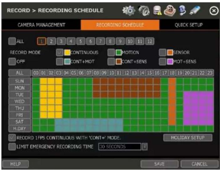
NO COLOR (Off)
No recording. Even though user-set recording frames in the "CAMERA" setup menu, the system will not record anything if the user sets "OFF" in the schedule table.
YELLOW (Continuous Recording)
Record all the time as set in the "CAMERA" settings.
GREEN (Motion-Detection Recording)
The system records only when motion is detected.
If "ALARM > CAMERA ALARM" is disabled, then the system will record when motion is detected but the motion alarm will not be activated.
ORANGE (Sensor-Activated Recording)
The system records only when a sensor is triggered as set in the "ALARM > SENSOR" menu. If "ALARM > SENSOR" is disabled, then the system will record when a sensor is triggered but the sensor alarm will not be activated.
SKY BLUE (Continuous + Motion Detection Recording)
The system records continuously as set by the "RECORD > CAMERA" menu.
When motion is detected according to the settings in "ALARM > EVENT ALARM", the NVR will switch recording mode to motion configuration. If "ALARM > EVENT ALARM" is disabled, then the system will record when motion is detected but the motion alarm will not be activated.
BROWN (Continuous + Sensor-Activated Recording)
The system records continuously as set by the "RECORD > CAMERA" menu.
When a sensor is triggered according to the settings in "ALARM > SENSOR", the NVR will switch recording mode to motion configuration. If "ALARM > SENSOR" is disabled, then the system will record when a sensor is triggered but the sensor alarm will not be activated.
PINK (Motion Detection + Sensor-Activated Recording)
The system records only when motion is detected AND when a sensor is triggered at the same time. If both "ALARM > SENSOR" and "ALARM > EVENT ALARM" is disabled, then the system will record
when a sensor is triggered, and motion is detected but neither sensor nor motion detection alarms will be activated.
| Note | In cases where the recording schedule is set by “CONT + MOT” or “MOT + SENS”, the system records by continuous or motion detection mode in normal operation. However, when motion occurs in the motion area or an alarm is activated, then the recording mode will switch to recording as set by “EVENT ALARM” or “SENSOR” of the “ALARM” menu. |
Note Dark Blue Color
The data recorded during DST (Daylight Saving Time) will be indicated in Dark Blue color in the Intelli-Search Bar in Playback Mode.
HOLIDAY SETUP
Set up specific days as “holidays” in HOLIDAY SETUP to assign a special recording schedule for those days. The system supports up to 32 holidays.
Press the [DATE] button (☐) write a description, and press [ADD] to save the data as a holiday.
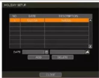
Note Instant Recording (Emergency Recording)
In the case of an emergency, the user enables Instant Record by pressing the panic recording button in the menu bar. The system will instantly start recording all the channels with the full-frame rate at the maximum resolution regardless of the recording mode setting.
E-REC will appear in Live Mode and a red-colored bar is shown in the time search bar for video recorded by instant recording.
RECORD 1FPS CONTINUOUS WITH 'CONT+' MODE.
Check the box to set continuous recording to 1FPS when selecting "continuous + xx" modes.
LIMIT EMERGENCY RECORDING TIME
Set a limit to how long the system will record in emergency recording mode. Select from 30sec/60sec/90sec/2min/5min/10min.
4.4.3. Quick Setup
Users can set up multiple cameras with the same recording at once.
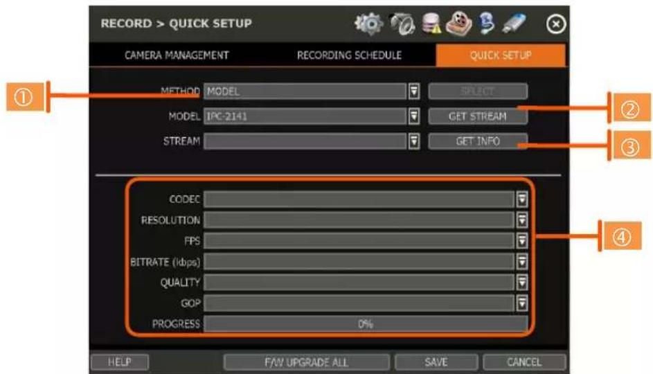
- Select the model or camera multi-select to set up. When selecting the 'Model' method, all
cameras with the same model's name will be selected.
-
When selecting 'Camera multi-select', the user can select the camera wanted to set. If you set the desired camera to 'ON', the user can set up the settings of the cameras set to ON.
-
Click the [GET STREAM] button and get the current stream information.
-
Click the [GET INFO] button and check the current setup for the cameras.
-
Change setup and click [SAVE].
-
"CAMERAS ARE SUCCESSFULLY APPLIED" message will appear when the process is completed.
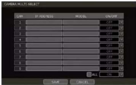
4.5 Network
The NVR can be connected to the network or Internet through either fixed IP or dynamic IP by the proper setting of the NVR and router.
4.5.1. Network
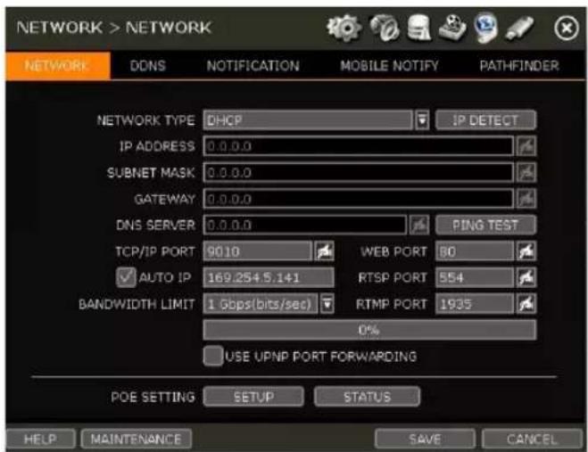
NETWORK TYPE
Select either STATIC IP or DHCP for dynamic IP. For proper configuration, it is recommended to assign the NVR a DHCP address and let the NVR auto-discover all the proper network settings, and then change the Network Type to Static IP and save the changes.
- DHCP: the NVR will automatically configure the network settings according to the current network requirements. If DHCP is selected, click the 'IP DETECT' button to automatically detect all the network settings.
- STATIC IP: manually enter all necessary network settings. While set to STATIC, the network settings will not change when prompted by the connected DHCP router or DHCP network device.
IP ADDRESS
Displays the NVR's IP address. If DHCP is selected, the IP address will automatically adjust to match the network's requirements. If STATIC is selected, the IP address can be manually changed as needed.
SUBNET MASK
Subnet Mask address classifies the subnet that the system belongs to. For more information, please consult your network administrator or your Internet provider.
GATEWAY
This is the IP address of the router or gateway server. It is required when connecting to the NVR through the external router over the Internet (from another network). For more information, consult your network administrator or your Internet provider.
DNS SERVER
Enter the IP address of the Domain Name Server. Input the DNS Server information to use DDNS, Email Notifications and NTP Server. For more information, please consult your network administrator or your Internet provider.
TCP/IP PORT
(Default - Port 9010) Input the network port number that is used when connecting to the NVR locally or remotely. If your ISP blocks Port 9010, you may either port forward the blocked port or change to use a different valid port number (ex, 9020). If there are multiple NVRs connected to the same local network, it should be considered to assign each NVR to different TCP/IP Ports.
WEB PORT
(Default - Port 80) Input the port number to use when connecting with a Web Browser. If your ISP blocks Port 80, you may either port forward the blocked port or change to use a different valid web port number (ex, 8080). If there are multiple NVRs connected to the same local network, it should be considered to assign each NVR to different Web Ports.
AUTO IP
Displays the system IP which is assigned through Auto-IP automatically.
BANDWIDTH LIMIT
(Default - 100 Mbps) Depending on the setting made by the user, the system can control the data volume transmitted over a network ranging from 25 kbps up to 1Gbps. This function is effective when under narrow bandwidth network conditions or when the user wants to limit “network bandwidth occupied by video transmission” to a certain level.
USE UPnP (Universal Plug and Play)
UPnP (Universal Plug and Play) Port Forwarding: If a UPnP supported router is connected, the NVR will forward ports automatically after communicating with the router without the need for complicated port forwarding setup at the router.
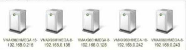
Once the PC has discovered the NVR using Network Discovery, double-click on the icon to open the NVR's web client. Enter the User ID and Password that is used to log in to the NVR then click 'Connect'.
Note The maximum number of simultaneous connections is 15 users.
POE SETTING
- SETUP: Manually configure the IP address and subnet mask for the cameras connected directly to the NVR's PoE switch.
- STATUS: his option decides the speed mode of the network (10Mbps or 100Mbps) at each POE port. Users can check the status of the cameras connected directly to the NVR's PoE switch and reset all PoE cameras as needed. Select from the options Auto (default), Normal, or Type-H. When cameras experience a long ping delay or connectivity issues, try setting the PoE's setting to Type-H. It is not recommended to have all ports set to Type-H.
Note This option is not available on 16CH Models. All ports work at 100Mbps mode only.
MAINTENANCE
Check the network status and set up the MAC address filter, IP address filter and HTTPS certificate.
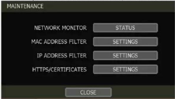
NETWORK MONITOR
Check the network status for each camera and data flow information for the NVR and cameras.
MAC ADDRESS FILTER
Block or allow specific MAC addresses of clients connecting using C3 CMS desktop software or mobile viewing application.
NOTE: This function works only on the local network and will not work for web login.
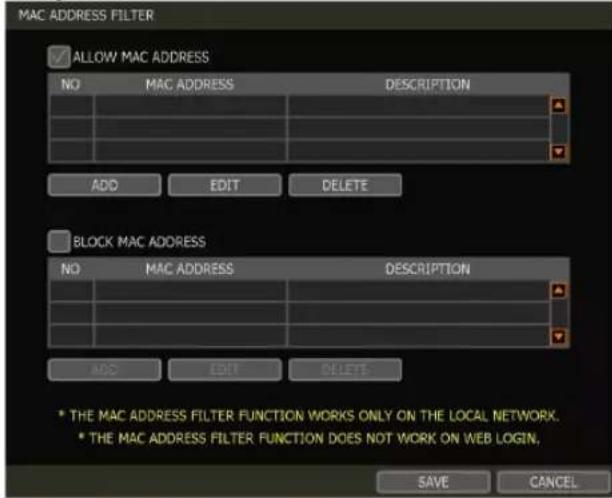
IP ADDRESS FILTER
This function allows or blocks a specific IP address. When the user registers a specific IP address to allow, only that address can access the module. Or when the user registers a specific IP address to block, that address can't access the module. This function is not working on web Login.
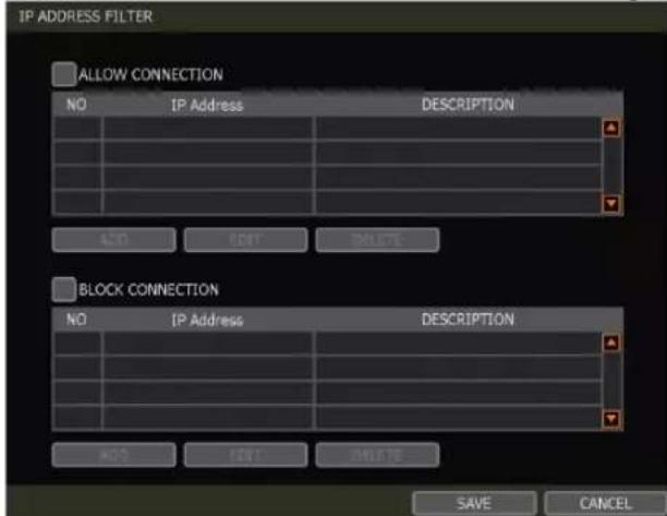
HTTPS/CERTIFICATES
An HTTPS connection is recommended when accessing the NVR remotely from another network. HTTPS connection offers secure access through encrypted communication.
The user must register a certificate for an HTTPS connection. The NVR provides two registration methods:
• Self-signed certificate: generate a certificate at the NVR.
• External certificate: register a certificate issued through an accredited authority.
To register a self-signed certificate, navigate to:
NETWORK>NETWORK>MAINTENANCE>HTTPS/CERTIFICATES
Click 'Generate' and fill out the information required. Fields marked with an '*' are mandatory.
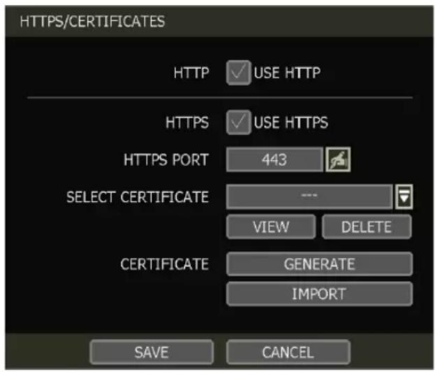
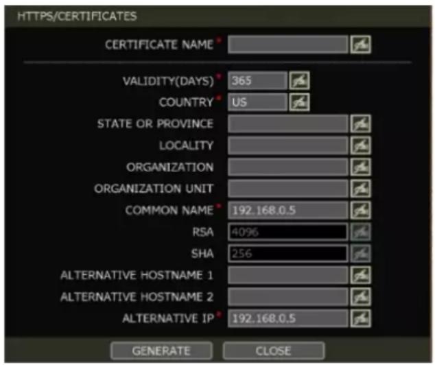
Note The NVR's time zone must be set BEFORE generating the certificate. The time on the NVR and network must match. Skipping this step may impact the validity of the generated certificate and the application time may vary.
When generating a self-signed certificate, a warning may appear when using an HTTPS connection because this certificate is not authenticated through an official authority. There is no problem with encrypted communication whether you register the certificate to the PC or continue with the warning ignored. To access the NVR via an HTTPS connection without the warning, you can import and use the certificate issued through an accredited certification authority.
To register an external certificate, click 'Import'. Locate and upload the certificate from a USB stick.
4.5.2. DDNS
Use a public DDNS server or the DDNS server run by Digital Watchdog (MYDWDDNS.NET) to connect with the NVR remotely.
DDNS SERVER
Digital Watchdog ^® offers free and dependable DDNS service support. This allows you to assign the NVR with a URL address rather than a long-complicated IP Address. This simplified the connection process to the NVR. The DDNS service is supported by Digital Watchdog ^® and is free of charge for our customers.
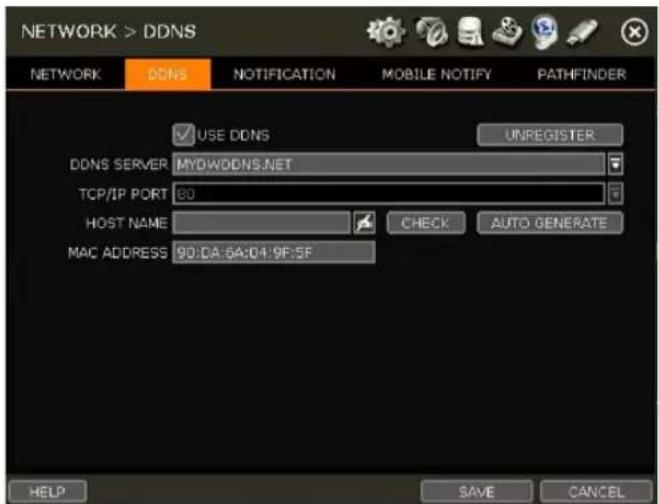
To set up DDNS, configure the following information then click the [SAVE] button.
- Use DDNS: Check this box to enable the use of DDNS address for remote communication with the NVR.
• DDNS SERVER: Select "MYDWDDNS.NET" - TCP/IP PORT: The default is 80. You do not need to change this setting if you are using the DDNS service provided by Digital Watchdog. Use the port information from the Network menu.
- HOST NAME: Assign a domain name for your NVR (Ex. NVROFFICE). If the domain name is unavailable, a message will pop up when you click [CHECK]. A random hostname can be automatically assigned by clicking [AUTO GENERATE].
IP MAPPING and EXTERNAL IP
If you are using IP Mapping and Port Forwarding (e.g., using a router for Internet connection), enable both [Use Device IP Mapping] and [Use External IP] for proper connection.
SETTING UP THE REMOTE SOFTWARE (C3 CMS)
In the menu of [Option > Setting], input DDNS Address and Port number.
The address of the DDNS SERVER is "mydwddns.net" and the Port is "80".
VIEWING WITH A WEB BROWSER
To connect with the NVR's Web Viewer, users can type the NVR's MAC address + mydwddns.net. In cases where you are using a subdomain name (HOST NAME), type the domain name + mydwddns.net
Example:
- If MAC address is "00:1C: 84:01:00:02" → input as http://001c84010002.mydwddns.net
- If the HOST NAME is "NVROFFICE" → input as "http:// NVROFFICE.mydwddns.net"
4.5.3. Notification
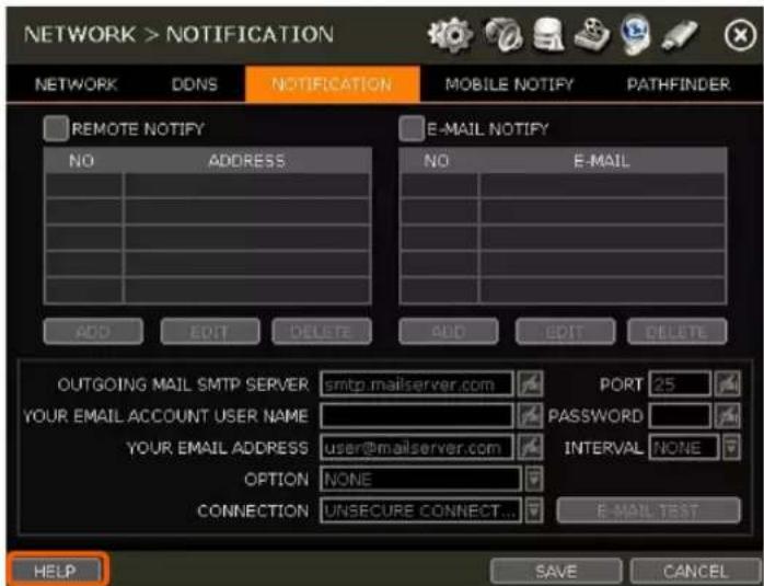
REMOTE NOTIFY
The system can send an alarm message to a remote viewing software by using the IP address of the hosting PC.
Select REMOTE NOTIFY to use this function and set IP address & events.
- IP ADDRESS: Input the IP address of the PC hosting the remote viewing software that will be receiving the event notifications.
- PORT: (Default is 8003) Input the port number that is used to communicate with the remote PC.
- EVENT: Select which events to be notified about. If "ALL" is selected, all events will trigger a remote notification.
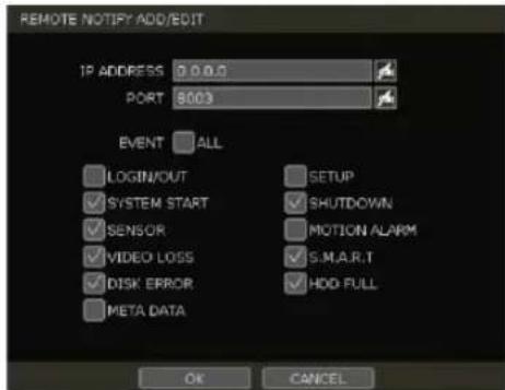
EMAIL NOTIFY
The system can send a notification to an email address.
Select EMAIL NOTIFY to use this function and set email addresses and events.
• EMAIL: Input the email address that will receive the events notifications.
- EVENT: Select which events will trigger notifications. If "ALL" is selected, all the events will trigger a notification.
- SNAPSHOT NOTIFY SETUP: Select camera channels to include live snapshot images of selected channels to the email address. Set the dwell time between camera image captures.
- VIDEO CLIP ATTACHMENT: Select to include a short video clip with the email notification when either a sensor or motion detection (CAMERA ALARM) has triggered the notification. The event type must also be selected.
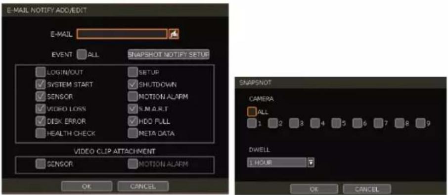
NOTIFICATION SETTINGS
- OUTGOING MAIL SMTP SERVER: Input the SMTP server that is being used to send the notifications. Check with your email service provider for SMTP server information.
- YOUR EMAIL ACCOUNT USER NAME: Input the username or email address from which the notifications will be sent.
- YOUR EMAIL ADDRESS: Input the email address of the account that will be used to send the email notifications.
- OPTION: Set the authentication method supported by the server. There are 'None/Use Plain Auth/No Auth' options.
- CONNECTION: Set the connection type supported by the email server. There are 'Unsecure Connection/Use SSL Authentication/Use TLS Authentication' options. Check with your email service provider for more information about authentication requirements.
- PORT: Input the port number that will be used for email sending. Check with your email service provider for more information on the port that is used for SMTP.
- PASSWORD: Input the email password to the account that is being used to send the notification emails.
- INTERVAL: For email notification, select how frequently the system will be allowed to send out an update email.
- EMAIL TEST: Click to check if the settings were entered correctly. The NVR will send a test email and inform you of the result. Depending on the email service, the SMTP server may not send an email confirmation if the email was received.
Note
Configuration priority is always on the "RECORD > SCHEDULE" menu.
The system will not email alarm messages upon motion alarm or sensor even though the checkbox of the above event is checked. To receive motion and sensor email notifications, set the "SCHEDULE > RECORD", "EVENT > MOTION ALARM" and "EVENT > SENSOR" accordingly.
4.5.4. Mobile Notify
The system can send an event notification to the mobile device registered with the NVR.
The mobile app “VMAX Plus” must be installed on your smartphone device and the NVR site must be added to the mobile application before registration for mobile push notifications can occur. The “USE PUSH CHECK” setting must be enabled in the VMAX Plus application for the NVR site.
When the mobile device is registered to the NVR correctly, it will appear on the Mobile Notify list, alongside a unique Device ID for the registered mobile device.
• USE MOBILE NOTIFY: Enable this setting to use mobile push notifications.
• EVENT: Select the event to notify.
- DELETE: To delete a listed mobile device, select the device then click the 'Delete' button. The USE PUSH CHECK setting in the VMAX Plus mobile application will then also be disabled.
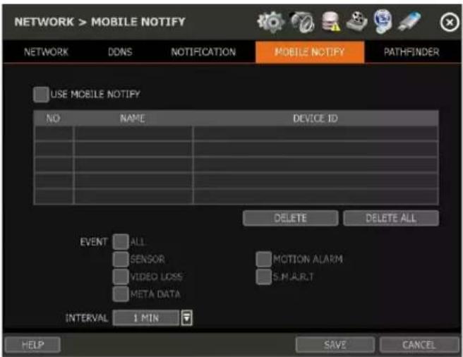
| NOTE | 1. The Mobile Push Notification function is available for iPhone, iPad & Android devices using the VMAX Plus mobile application. Otherwise, the mobile application “DW Mobile Plus” can be used for general remote viewing with the NVR.2. The maximum number of mobile devices is 50. |
| NOTE | Push Notification will only work when both the NVR and mobile devices have a direct connection using the local network (LAN) or over a remote Internet connection. Direct connection (IP address) is needed as PathFinder connections may not support push notifications. |
4.5.5. PathFinder™
PathFinder uses STUN communication to assist with the encryption and stream security between the viewer and the NVR when connected using DW's connection service. This connection method offers an alternative means to view video from the NVR over a remote connection without the need for port forwarding.
- USE PATHFINDER: Enable this setting to activate the PathFinder service for the NVR. Click SAVE to apply the changes.
- PATHFINDER ID: A unique 21-character alphanumerical identification number will be generated for the NVR. This ID can be either used to connect with a web browser (www.ezpathfinder.com/p2p) or by being manually entered into the DW Mobile Plus mobile viewing application.
- QR CODE: Users can scan the QR code using the DW Mobile Plus or VMAX Plus mobile viewing applications to automatically enter the PathFinder ID into the site settings while registering the NVR within the mobile application.
- STATUS: Users can check the NVR's PathFinder status at the bottom of the screen.
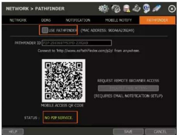
QR code menu (PATHFINDER service is not in use)
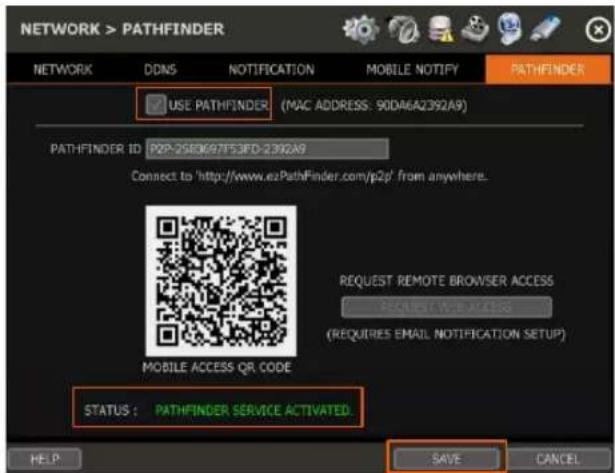
QR code menu (PATHFINDER service is in use)
Note Please refer to "Section 6. PathFinder Connection Through the Web" for the details.
4.6 Export
4.6.1. Manual Export
Users can easily export recorded video from the NVR to a USB memory stick.
- In Live Mode, click the [EXPORT] icon in the menu bar to open the EXPORT menu.
- In Playback Mode, press the [QUICK EXPORT] icon in the menu bar. Pressing it once will indicate the start time for the backup file. Click the icon again to indicate the end time for the backup clip. The EXPORT menu screen will appear.
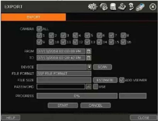
- Connect an appropriate USB memory stick and press [SCAN] to recognize it before starting the export process. The USB device must use FAT32 format to be recognized by the NVR.
- Adjust the following options for the video export as needed:
- CAMERA: Select the camera channels to be included in the exported file. Select 'ALL' to include all camera channels.
• FROM: Set the start time of the exported video.
• TO: Set the end time of the exported video.
- DEVICE: Click [SCAN] to detect the connected USB memory stick. The USB device must be using FAT32 format.
- FILE FORMAT: The exported video clip will be saved in .SSF file type and can only be viewed using the DW Backup Viewer tool or with a media player that supports SSF format.
- FILE SIZE: Click the [ESTIMATE] button to calculate the estimated file size. If the file is too large, reduce the number of camera channels or the length of the video footage to reduce the size.
- ADD VIEWER: Enable this setting include the Backup Viewer with the archived file, which can be used to view the exported SSF video file on a PC.
- PASSWORD: Add a password to protect the file if needed. The password will need to be entered to view the file on a PC.
- Click [START] to start the export process. A progress bar will appear on the screen. Click the [CANCEL] button to abort the export process. DO NOT remove the USB until the file export has been completed.
NOTE
A user, who is not an ADMIN user, can access the Export menu only if their user account has both the Export function and menu access authorization enabled by the system administrator.
4.6.2. Backup Video Playback
If [ADD VIEWER] is selected, the backup image can be reviewed on a PC with no need to install additional software. Once the backup device (USB) is connected to a PC the files will appear in the exported folder.
- To play recorded data, open the exported folder and double-click the "MultiBackupPlayer.exe" file. In the Backup Player, open the video data file (SSF format) that you wish to playback.
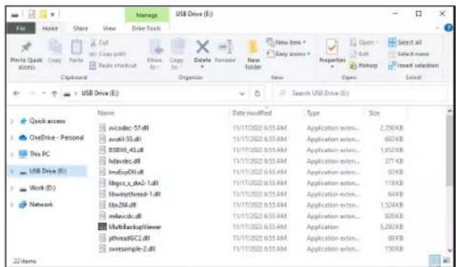
-
To playback a single channel, click the [SINGLE CH] tab (①) and select an SSF file to playback then drag it into the viewing area.
-
To playback, multiple channels, click the [MULTI CH] tab and 'Search' to open the folder that keeps all SSF files.
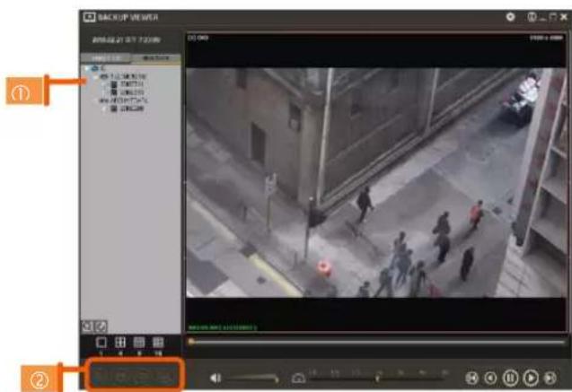
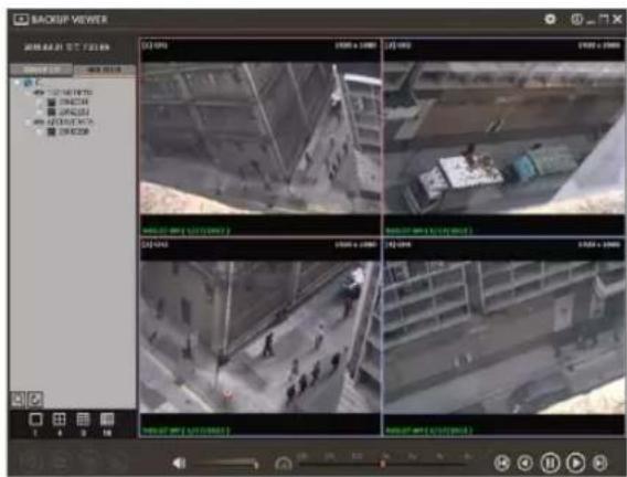
You can print or export an image and digital zoom by using the icons (②) at the bottom-left of the player window.
Option MENU
Various settings are available in the OPTIONS window of the backup player software.
- Use Delinterlace: The user can uncheck the Delinterlace checkbox in the "Option" menu. Some PCs do not support "Delinterlace".
- Show Image Info on Snapshot: The image information will be added as a text overlay when exporting an image.
WATERMARK Verification and Convert to AVI File
Convert the backup file to an AVI file to play the file in ordinary media players. The third-party media player must support AVI files.
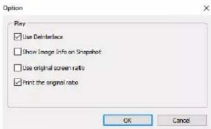
- Playback the SSF file in Single CH mode and click [Pause].
- Click [AVI Convert].
- Define the start and end times.
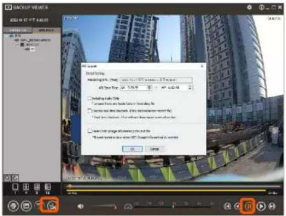
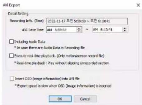
When the AVI file is played back in the Backup Viewer, verify whether the file has been altered or not by pressing the [Watermark] button (☐). If the file has been altered, a popup message will appear.
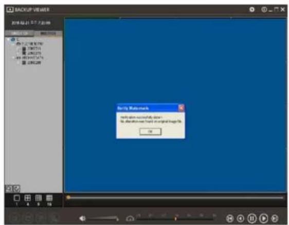
No alteration was found
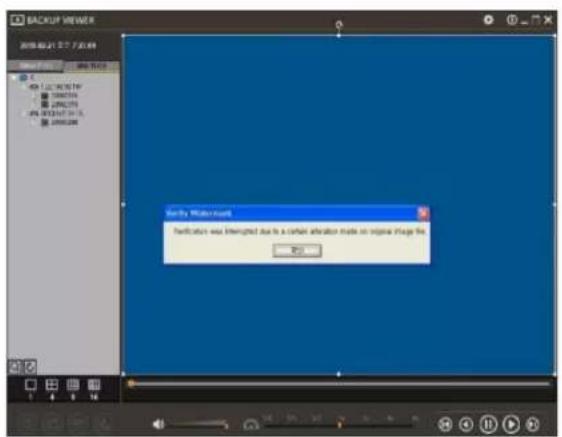
AVI video clip has been altered
5. Web Surveillance with Web Browser
The VMAX ^® IP G4 ^™ has a built-in web server by itself. This allows you to access the system by an ordinary web browser via the network for live monitoring, playback, or remote configuration without installing any additional software.
5.1 Web Login
Using a web browser (Google Chrome is recommended), type the NVR's IP Address or DDNS address in the address bar. If the Web Port is set to the default (Port 80), the URL would be "192.168.1.80", which is the equivalent of "192.168.1.80:80". However, if the Web Port was changed to "85", the URL would look like "192.168.1.80:85".
When the login page appears, enter the user ID and password. The default user ID is “admin” and the password is set by the administrator when the NVR is booted-up for the first time.
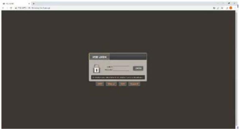
5.2 Web Monitoring
After logging in, the live view from the NVR will appear on the web page automatically. Users can also select Playback, Setup, QSG, Manual, FAQ, Support, or Logout.
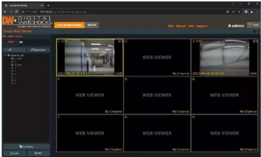
LIVE
Users can connect or disconnect all channels and select a specific channel to view in live or Playback Mode.
TIME TABLE
Users can open the timetable and playback at any time they want.
MODE
Users can change screen mode.
PTZ
Users can control Pan/Tilt, Zoom In/Out, Focus In/Out and Preset buttons to control PTZ cameras connected to the NVR.
POP-UP MENU
Right-click to open additional options:
- Close all Channels: Close all channels.
- Close the selected channels: Close the selected channels.
- Go To Live / Playback: Change to Live or Playback Mode.
- Panoramic View: Change screen mode to horizontal, vertical, or quad-screen mode.
• Stream Type: Set the stream type. (Auto / 1 ^st / 2 ^nd )
• Show Text: Set the information to display. (Channel title / Mode [Live/Playback] / Date / Time / Resolution)
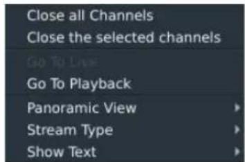
5.3 Web Playback
To remotely playback video from the NVR, click the timetable or [Go To Playback] from the pop-up menu.
PLAYBACK TIME
Select the date and time from the timetable.
Intelli-search bar
Move the red-vertical line to the time that the user wants to search. The colors of the time bar indicate the different recording modes. Refer to "4.3.2" for more information.
Playback controls
Use the Fast Forward, Rewind and Play/ Pause buttons to control the playback video.
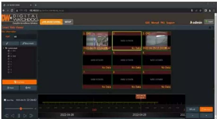
DW
5.4 NVR's Setup Menus from the Web Viewer
| Main Classification | Sub Classification |
| SYSTEM | INFORMATION |
| USER | |
| DISPLAY | |
| HDD | |
| UPGRADE | |
| CONFIGURATION | |
| DEVICE | CAMERA |
| AUDIO | |
| KEYBOARD | |
| EVENT | SENSOR |
| CAMERA ALARM | |
| EXTRA ALARM | |
| RECORD | CAMERA MANAGEMENT |
| REGISTRATION | |
| SCHEDULE | |
| NETWORK | NETWORK |
| DDNS | |
| NOTIFICATION | |
| PATHFINDER | |
| HTTPS/CERTIFICATES | |
| CERTIFICATE GENERATION | |
| CERTIFICATE IMPORT | |
| LOG | SYSTEM LOG |
| EVENT LOG | |
| VIDEO ANALYTICS LOG | |
| IVA LOG |
| NOTE | This NVR system has a built-in web server.Therefore, this web CGI screen is directly supported by the built-in web server of NVR regardless of the Internet connection. |
| NOTE | SYSTEM REBOOT enables users to reboot the system without any change to the setup. Users can use this function when the network is disconnected due to abnormal operation of the system and try to reconnect. IP number assigned to the system may be changed in the case of DHCP mode. |
6.PathFinder™ Connection Through the Web
6.1 myDW™ PathFinder Login
To connect to the NVR through Pathfinder from the web, input the address of 'https://pf.mydw.cloud' in the web and open the following login screen.
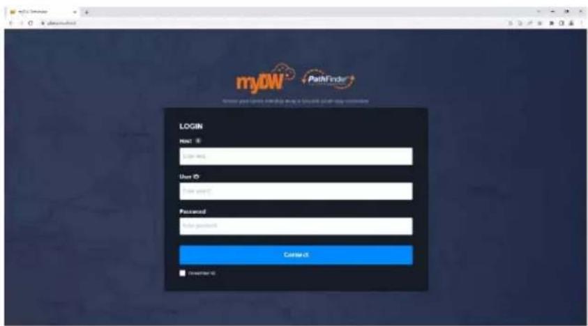
- Host: Enter the IP address, URL, or PathFinder ID for the NVR to connect.
• User ID: Enter the user ID of the DVR to connect. - Password: Enter the password of the DVR to connect.
6.2 Live
After logging in, the live view from the NVR will appear on the web page automatically.
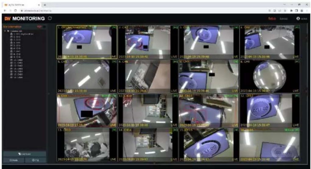
Users can connect or disconnect all channels and select a specific channel to view in live or Playback Mode.
- LIVE: Users can connect or disconnect all channels and select a specific channel to view in live or Playback Mode.
• TIME TABLE: Users can open the timetable and playback at any time they want.
• MODE: Users can change screen mode.
- PTZ: Users can control Pan/Tilt, Zoom In/Out, Focus In/Out and Preset buttons to control PTZ cameras connected to the NVR.
• POP-UP MENU: Right-click to open additional options:
- Close all Channels: Close all channels.
- Close the selected channels: Close the selected channels.
- Go To Live / Playback: Change to Live or Playback Mode.
- Panoramic View: Change screen mode to horizontal, vertical, or quad-screen mode.
Stream Type: Set the stream type. (Auto / 1 ^st / 2 ^nd )
Show Text: Set the information to display. (Channel title / Mode [Live/Playback] / Date / Time / Resolution)
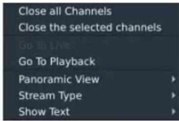
6.3 Playback
To remotely playback video from the NVR, click the timetable or [Go To Playback] from the pop-up menu.
- PLAYBACK TIME: Select the date and time from the timetable.
- Intelli-search bar: Move the red-vertical line to the time that the user wants to search. The colors of the time bar indicate the different recording modes. Refer to "4.3.2" for more information.
- Playback controls: Use the Fast Forward, Rewind and Play/ Pause buttons to control the playback video.
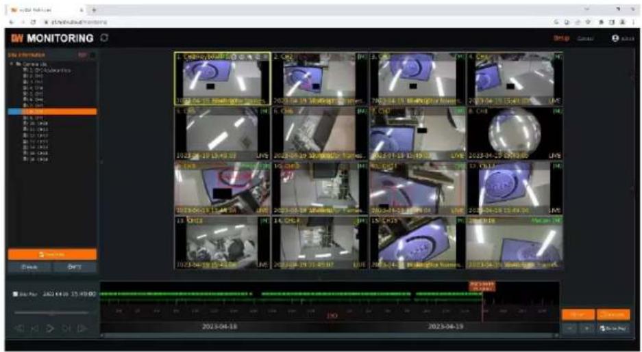
6.4 Setup
Users can open new screen for web setup by clicking 'Setup' in the upper-right corner of the screen. Recorder settings can be configured by the administrator with these menus.
7. Q & A
- NVR does not record images in sensor mode and/or motion mode.
1) It records images only when there is an event for the corresponding mode.
2) Check that the settings are correct in the menus: [Event > Sensor], [Event > Camera Alarm], and [Record > Schedule].
- There is an HDD installed but the "No HDD" icon (BBD) is still shown on the screen.
1) Check the cable connection of the HDD again.
2) If you can see the HDD list at [System > HDD] but the capacity indicates "O", the HDD requires format.
- There is nothing displayed on the True HD/VGA monitor though electric power is supplied to the NVR.
1) Check if the power is supplied properly. You should be able to hear the noise from the fan and HDD operation.
2) Check the True HD/VGA cable connection with the NVR. Remove all the cable connections, except for the monitor cable, and then apply power to the NVR again.
3) In cases where the display screen is stopped at the logo screen, please contact Digital Watchdog's technical support for additional information.
- Is it necessary to open the port when using DDNS?
Yes, it is. DDNS is the function that lets remote connections acknowledge the changed address of the NVR (dynamic IP provided by ISP) or allow connection to the NVR by the domain without memorizing IP.
- The remote software connection to the NVR works fine but the WEB connection doesn't work.
1) Some ISP blocks port number 80. Please try again after changing the WEB port.
(8080 is the recommended alternative)
2) Check whether port 80 is opened or not.
- Image is not shown after login at WEB monitoring.
TCP Base port should be opened. The default of the TCP base port is 9010.
- The image on the remote software has suddenly disappeared after displaying it for a brief time.
1) Some ISPs restrict upload data/traffic volume. Please contact your ISP.
2) Upload traffic restrictions can be easily checked with the following steps.
Turn off the power of your Modem & Router.
After 60 seconds, turn on the power of your Modem first and then Router.
After reconnection, if it is disconnected again after a brief time (in a similar period later), it means that the ISP restricts upload traffic.
- A backup or firmware upgrade through a USB memory stick cannot be made though it is detected by the NVR.
1) USB memory stick should be formatted by FAT or FAT 32.
2) It is not allowed to use a partitioned or password-encoded USB memory.
- Time sync through the NTP server does not work.
The NTP server requires a DNS server address. Check if the DNS server address is correct at the [Network] setup page.
- Email transmission does not work in using the Email to notify function.
1) The Email notification function works based on the SMTP service.
2) Check if the sending mail address is correct and if the mail server supports the SMTP service.
3) If you are using an SMTP service that is based on TLS authentication (including SSL) such as Gmail and yahoo mail, enable [Use SSL Authentication] at the [Notification] setup page.
4) SMTP service is provided based on DNS. Check if the DNS server address is correct at the [Network] setup page.
- Specifications
| MODELS | DW-VG416xT16P | DW-VG412xT8P | DW-VG49xT4P | |
| VIDEO | ||||
| Operating system | Embedded Linux® | |||
| System | channel | 16 channels | 12 channels | 9 channels |
| No. of PoE | 16Ch | 8 Ch | 4 Ch | |
| Max supported resolution | IP camera max. 4K (3840×2160) | |||
| Communication protocol | ONVIF® Profile S | |||
| PoE type | 1Gbps, 802.3at | |||
| Display | Speed | 480fps | 360fps | 270fps |
| Screen mode | 1, 4, 9 and 16 | 1, 4, 9 and 12 | 1, 4 and 9 | |
| Video-out | Monitor | True HD and VGA | ||
| Resolution | 3840×2160 (4K), 1920×1080, 1280×1024, 1024×768 | |||
| System operation | USB mouse, PTZ control by keyboard (optional) | |||
| PERFORMANCE | ||||
| Recording speed | Up to 480fps | Up to 360fps | Up to 270fps | |
| Up to 4K (2160p) resolution | ||||
| Max. throughput | 160 Mbps | 80 Mbps | 40 Mbps | |
| Recording streaming | Dual stream | |||
| Recording modes | Continuous, scheduled, sensor and motion detection recording | |||
| Pre- and post-alarm recording, emergency recording, quick backup | ||||
| Playback and search | Speed | x1, x2, x4, x8, x16, x32, x64, x99 | ||
| Channel and resolution | 1 and 4 mainstream, 9 & 16: sub-stream | |||
| Function | Timeline, calendar (date and time), event search, thumbnail search, smart motion search | |||
| Audio input / output | 1Ch input/1Ch output | |||
| Alarm input / relay output | 8Ch inputs/4Ch outputs | 4Ch inputs/1Ch output | 4Ch inputs/1Ch output | |
| PTZ control | RS-485, ONVIF | |||
| Storage | HDD interface | 2x SATA HDD | 2x SATA HDD | 1x SATA HDD |
| Max. internal storage | Up to 32TB | Up to 32TB | Up to 16BT | |
| HDD health check | Temperature, S.M.A.R.T. with email notifications Real-time temp alert | |||
| Transaction verification | Text-in Based (USB to Serial support, TCP/IP Network), Display POS Data on Live & Playback | |||
| NETWORK | ||||
| LAN | 1,000Mbps Ethernet (RJ45) | |||
| Protocols | IPv4, TCP/IP, DHCP, HTTP, RTSP, STMP, FTP, Zero Configuration, NTP, DDNS | |||
| Access | Web viewer | Live, playback and configuration, up to 10 connections | ||
| Video streaming functions | Dual recording for live and playback and dual stream for local recording and network transmission | |||
| PathFinder^TM easy end-to-end remote connection | ||||
| Monitoring software | C3^TM CMS, DW Mobile Plus ^TM | |||
| Network functions | Live monitoring, remote playback, and file backup | |||
| Remote system control | Remote system reboot, system management, notifications and remote PTZ control | |||
| Remote Time sync | Time synchronization to an NTP server (pool.ntp.org) | |||
| Remote system notifications | Notifications for system health, events, and alarms | |||
| System recovery after power failure | Auto-reboot and journaling file system | |||
| Other function | Firmware upgrade | FTP, USB, and CMS over Network | ||
| Back-up | Local backup by USB, network backup by CMSImport and export settings, watermark, and AVI file backup | |||
| Special features | Snapshot Notify^TM : Interval camera image verificationEvent and push notifications via email, text and C3^TM Digital Zoom in live and playbackPOS text-in based (USB to serial support, TCP/IP network) | |||
| Mobile client | DW Mobile Plus app for Apple®and Android®devicesDW Witness ^TM turns a smartphone or tablet into a surveillance camera | |||
| Health check | Real-time system, network and PoE status monitoring | |||
| GENERAL | ||||
| Operating temp and humidity | 32-113 °F (0-45 °C) / 10-90% RH | |||
| Certification | CE, FCC, KC, NDAA, TAA | |||
| System | Power requirement | 54V DC, 3.33A | 48V DC, 2.5A | 48V DC, 1.25A |
| Power consumption | 180W (recorder + PoE ports) | 120W (recorder + PoE ports) | 60W (recorder + PoE ports) | |
| PoE | Max power per port | 802.3at POE+(Class4), up to 30W per port | 802.3at POE+(Class4), up to 30W per port | 802.3at POE+(Class4), up to 30W per port |
| Total PoE power budget | 150W | 96W | 48W | |
| Dimension (W x D x H) | 14.96" x 10.55" x 1.77"(380 x 268 x 45 mm) | 14.96" x 10.55" x 1.77"(380 x 268 x 45 mm) | 11.81" x 9.8" x 1.77"(300 x 249 x 45 mm) | |
| Warranty | 5 year limited | |||
* Specifications are subject to change without notice.
9.Warranty Information
Go to https://digital-watchdog.com/page/rma-landing-page/ to learn more about Digital Watchdog's warranty and RMA.
To obtain warranty or out of warranty service, please contact a technical support representative at: 1+ (866) 446-3595, Monday through Friday from 9:00 AM to 8:00 PM EST.
A purchase receipt or other proof of the date of the original purchase is needed before warranty service is rendered. This warranty only covers failures due to defects in materials and workmanship which arise during normal use. This warranty does not cover damages that occur in shipment or failures which are caused by products not supplied by the Warrantor or failures which result from accident, misuse, abuse, neglect, mishandling, misapplication, alteration, modification, faulty installation, setup adjustments, improper antenna, inadequate signal pickup, maladjustments of consumer controls, improper operation, power line surge, improper voltage supply, lightning damage, rental use of the product or service by anyone other than an authorized repair facility or damage that is attributable to acts of God.
10.Limits and Exclusions
There are no express warranties except as listed above. The Warrantor will not be liable for incidental or consequential damages (including without limitation, damage to recording media) resulting from the use of these products or arising out of any breach of the warranty. All express and implied warranties, including the warranties of merchantability and fitness for a particular purpose, are limited to the applicable warranty period set forth above.
Some states do not allow the exclusion or limitation of incidental or consequential damages or limitations on how long an implied warranty lasts, so the above exclusions or limitations may not apply to you. This warranty gives you specific legal rights, and you may also have other rights from vary from state to state.
If the problem is not handled to your satisfaction, then write to the following address:
Digital Watchdog, Inc.
ATTN: RMA Department
16220 Bloomfield Ave
Cerritos, CA 90703
Service calls that do not involve defective materials or workmanship as determined by the Warrantor, in its sole discretion, are not covered. The cost of such service calls is the responsibility of the purchaser.
- WARNING
- Cautions
- Signs of Caution and Warning
- General Warning
- Caution
- Cautions about the Power
- Remarks
- Table of Contents
- GETTING STARTED 6
- STARTUP WIZARD ....12
- OPERATION....18
- NVR SETTINGS MENU 42
- WEB SURVEILLANCE WITH WEB BROWSER....79
- PATHFINDER CONNECTION THROUGH THE WEB....82
- Q & A 84
- Getting Started
- Checking Supplied Items
- System Startup
- Connect External Devices
- System Startup
- System Shutdown
- Note
- System Explanation
- Front Panel
- The Toolbar in Live Mode
- Menu
- Display Mode
- Sequence
- Channel
- Emergency Recording
- Backup
- Playback
- Search
- Exit
- Pin
- The Toolbar in Playback Mode
- Intelligent Search Bar
- Previous/Next Date Search
- Playback Controls
- Screen Display Mode
- Startup Wizard
- Language
- Date/Time
- TIME SYNC MODE
- HDD Format
- HDD FULL
- HDD CHECK
- HDD FORMAT
- AUTO DELETE
- Network
- NETWORK TYPE
- IP ADDRESS
- SUBNET MASK
- GATEWAY
- DNS SERVER
- TCP/IP PORT
- WEB PORT
- AUTO IP
- BANDWIDTH LIMIT
- USE UPnP (Universal Plug and Play)
- Camera Management
- Auto-Configuration (1)
- Drag & Drop Configuration (2)
- Advanced Configuration (3)
- Product Registration and Finish
- Operation
- User Log-in
- Camera Registration
- PoE Camera Connection
- Camera Connection through Network
- Auto Configuration
- Drag and Drop Configuration
- Advanced Search
- Multi-Select
- Manually Add Cameras
- Deleting Cameras
- Camera Setup
- Setup for Each Camera
- Note CCIP™ Encryption Option
- Quick Setup
- Change Channel
- Live Display Mode
- Channel Selection
- Icons
- Pop-up Menu
- CHANGE NEXT CH
- DIGITAL ZOOM
- IMAGE ADJUSTMENT
- PTZ
- CAMERA SETUP
- FREEZE
- ADD BOOKMARK
- INSTANT PLAYBACK
- SMART SEARCH
- SPECIAL CAM SEARCH
- RECORDING INFO
- SYSTEM STATUS
- ANALYSIS
- HEALTH CHECK
- PTZ Operation
- PTZ Control
- ZOOM/FOCUS
- PRESET
- TOUR
- GUARD TOUR
- GOTO HOME
- SETUP
- PTZ EXIT
- Playback Recorded Images
- Date/Time (1)
- Toolbar (2)
- Pop-up Menu (3)
- Exit Playback Mode (4)
- Search Recorded Video
- Calendar Search
- Search Date/Time
- First Data
- Last Data
- System Log
- Event Log
- HDD Log
- Transaction Verification
- Bookmark
- Smart Search
- Preview Search
- Advanced Preview Search
- Special Camera Search
- Video Analytics
- DST Setting and Image Playback
- DST Setting
- DST Image Playback
- MEGApix® IVA™ Analytics
- IVA Settings
- ALARM MANAGER
- MEGApix IVA EVENT SEARCH
- 4.NVR Settings Menu
- System
- Information
- SITE NAME
- KEYBOARD ID
- REMOTE ID
- DATE/TIME
- LANGUAGE
- VERSION
- Upgrading system using USB memory stick:
- Upgrading system via FTP server:
- To set up the NVR to check for new firmware automatically:
- MAC ADDRESS
- SERIAL
- SYSTEM / PERFORMANCE MONITOR
- KEYPAD BEEP
- 4.1.2.User
- User Management
- Add User
- Delete User
- Option
- Setting Authorized Level at the Remote Software (C3 CMS)
- Display
- SEQUENCE TIME
- DISPLAY RESOLUTION
- OSD
- SCREEN SAVER
- CHANNEL SWAP
- VIDEO ENHANCEMENT
- HDD
- WARNING MESSAGE
- System Settings
- STARTUP WIZARD
- FACTORY DEFAULT
- EXPORT/IMPORT
- Device
- Camera
- TITLE
- COVERT
- PRIVACY MASK
- CAMERA ADJUST
- Audio (Live and Recording)
- PTZ
- PROTOCOL
- BAUD RATE
- ADDRESS
- CONTROL (The functions depend on the camera's model and supported features)
- Transaction Verification Settings
- NO
- CAM
- TYPE
- SAVE
- SHOW
- SETUP (1)
- Live Display Settings
- PORT SETUP (3)
- Keyboard
- Alarm
- Sensor
- ON/OFF
- RELAY
- DWELL (Post Alarm)
- PRE-ALARM
- NOTIFY
- Camera Alarm
- DWELL
- MOTION AREA
- COPY SETTING
- EVENT MONITOR
- Extra Alarm
- S.M.A.R.T.
- VIDEO LOSS
- DISK ERROR
- DISK FULL
- Record
- Camera Management
- DEL
- DELETE PAGE (2)
- DELETE ALL (3)
- CAMERA REGISTRATION (4, 5, 6, 7)
- Recording Schedule
- NO COLOR (Off)
- YELLOW (Continuous Recording)
- GREEN (Motion-Detection Recording)
- ORANGE (Sensor-Activated Recording)
- SKY BLUE (Continuous + Motion Detection Recording)
- BROWN (Continuous + Sensor-Activated Recording)
- PINK (Motion Detection + Sensor-Activated Recording)
- Note Dark Blue Color
- HOLIDAY SETUP
- Note Instant Recording (Emergency Recording)
- RECORD 1FPS CONTINUOUS WITH 'CONT+' MODE.
- LIMIT EMERGENCY RECORDING TIME
- Quick Setup
- Network
- Network
- POE SETTING
- MAINTENANCE
- NETWORK MONITOR
- MAC ADDRESS FILTER
- IP ADDRESS FILTER
- HTTPS/CERTIFICATES
- DDNS
- DDNS SERVER
- IP MAPPING and EXTERNAL IP
- SETTING UP THE REMOTE SOFTWARE (C3 CMS)
- VIEWING WITH A WEB BROWSER
- Example:
- Notification
- REMOTE NOTIFY
- EMAIL NOTIFY
- NOTIFICATION SETTINGS
- Mobile Notify
- PathFinder™
- Export
- Manual Export
- Backup Video Playback
- Option MENU
- WATERMARK Verification and Convert to AVI File
- Web Surveillance with Web Browser
- Web Login
- Web Monitoring
- LIVE
- TIME TABLE
- MODE
- POP-UP MENU
- Web Playback
- PLAYBACK TIME
- Intelli-search bar
- 6.PathFinder™ Connection Through the Web
- myDW™ PathFinder Login
- Live
- Playback
- Setup
- Q & A
- 9.Warranty Information
- 10.Limits and Exclusions
Brand : Digital Watchdog
Model : VMAX IP G4 DW-VG416
Category : Video recorder