
HMK60 - Heat pump MITSUBISHI - Free user manual and instructions
Find the device manual for free HMK60 MITSUBISHI in PDF.

| Product Type | Air-to-Air Heat Pump (Split System) |
| Model | HMK60 |
| Brand | Mitsubishi |
| Cooling Capacity (kW) | 6.0 |
| Heating Capacity (kW) | 6.8 |
| Power Supply | 230V / 50Hz / Single Phase |
| Dimensions (Indoor Unit) - Height | 800 mm |
| Dimensions (Indoor Unit) - Width | 300 mm |
| Dimensions (Indoor Unit) - Depth | 200 mm |
| Dimensions (Outdoor Unit) - Height | 550 mm |
| Dimensions (Outdoor Unit) - Width | 800 mm |
| Dimensions (Outdoor Unit) - Depth | 300 mm |
| Weight (Indoor Unit) | 15 kg |
| Weight (Outdoor Unit) | 35 kg |
| Refrigerant Type | R32 |
| Energy Efficiency Ratio (EER) | 3.5 |
| Main Functions | Cooling, Heating, Dehumidification, Fan Only, Auto Mode, Sleep Mode, Timer, Swing Louver, Self-Cleaning |
| Maintenance & Cleaning | Clean air filter every 2 weeks; wipe indoor unit with damp cloth; avoid water on electrical parts. |
| Safety Features | Overload protection, anti-freeze protection, compressor delay start, auto restart after power failure. |
| Spare Parts & Repairability | Common spare parts available: filters, fans, PCBs, compressors. Authorized service centers recommended. |
Frequently Asked Questions - HMK60 MITSUBISHI
User questions about HMK60 MITSUBISHI
0 question about this device. Answer the ones you know or ask your own.
Ask a new question about this device
Download the instructions for your Heat pump in PDF format for free! Find your manual HMK60 - MITSUBISHI and take your electronic device back in hand. On this page are published all the documents necessary for the use of your device. HMK60 by MITSUBISHI.
USER MANUAL HMK60 MITSUBISHI
Air to Water Heat Pump
Hy drolution (HM)
HSB60/HMK60/FDCW60VNX-A
PT300/RC-HY20/40
Safety precautions 2
General information for installer 7
Over view and design 7
Transport and storage 10
Supplied components 10
Assembly 10
Hanging indoor unit 12
Hanging control unit 12
Dimensioning expansion vessel 13
Recommended installation order 13
Pipe installation 14
General 14
Installation diagram 14
HSB60 14
HMK60 15
System requirements 16
Overflow valve 16
Pump capacity diagram 16
Pressure drop in indoor unit 17
Dimensions and pipe connections 17
HSB60 17
HMK60 17
PT300 18
Water circuit 19
Connection to heating system 19
Connection to hot water heater 19
Housing disassembly of tank unit 19
Connecting hot water tank to indoor unit 20
Connecting hot water tank to water main 21
Hot water circulation circuit 22
Connection of external heat source 23
Refrigerant circuit 23
Connecting refrigerant pipes 23
Piping insulation 23
Drain connection 23
Dockings 24
Electrical installation 29
General 29
Electrical components 30
Accessibility, electrical connection for controller 32
Cable lock 34
Connection 34
Power supply 34
Connection between indoor and outdoor unit 34
Connection between indoor unit and controller 35
Cascade connection setting 35
Recommended fuse size for HSB60 35
Recommended cable size for HSB60 35
Circuit breaker 35
Power supply 35
Connection between indoor and outdoor unit 36
Connection between indoor unit and controller 36
Recommended fuse size for HMK60 36
Recommended cable size for HMK60 35
Power supply 36
Connection between controller and indoor unit 37
HSB60 with RC-HY20 37
HSB60 with RC-HY40 37
HMK60 with RC-HY20 37
HMK60 with RC-HY40 37
Connection between controller and circulation pump (GP12) 38
HSB60 with RC-HY20 38
HSB60 with RC-HY40 38
HMK60 with RC-HY20 39
HMK60 with RC-HY40 39
Connection between controller and 3-way valve (QN10/QN12) _ 40
HSB60 with RC-HY20 40
HSB60 with RC-HY40 40
HMK60 with RC-HY20 41
HMK60 with RC-HY40 41
Connection between controller and sensors 42
RC-HY20 with HSB60 42
RC-HY20 with HMK60 43
RC-HY40 with HSB60 45
RC-HY40 with HMK60 46
Optional connections 48
RC-HY20 48
• Room sensor BT50 48
- Step controlled additional heat 48
Connection example with HMK60 49
- Relay output for emergency mode 49
Connection example with HMK60 50
- External circulation pump 50
- AUX inputs/outputs 50
- myUpway™ 52
RC-HY40 53
- Load monitor 53
- Room sensor BT50 53
- Step controlled additional heat 53
- Relay output for emergency mode 53
- External circulation pump 53
- AUX inputs/outputs 54
- myUpway™ 55
Commissioning and adjusting 56
Preparation 56
Filling and venting 56
Hot water tank 56
Climate system 56
Inspection of installation 56
Start-up and inspection 57
Before start-up 57
Commissioning with heat pump 57
Commissioning with additional heater only 57
3-way valve operation check 57
AUX function check 57
Cooling mode 57
Cleaning particle filter 57
Secondary adjustment 57
Start guide 58
Heating/cooling curve setting 59
Hot water circulation setting 60
SG ready 61
Control 62
Display unit 62
Menu system 63
Menu list 66
Menu 1 – Indoor climate 66
Menu 2 – Hot water 66
Menu 3 – Info 66
Menu 4 – My system 66
Menu 5 – Service 67
Service 75
Disturbances in comfort 78
Manage alarm 78
Troubleshooting 78
Additional heating only 79
Alarm list 80
Accessories 83
Technical data 84
Dimensions and setting-out coordinates 84
Electrical circuit diagram 85
Safety precautions
When installing the unit, be sure to check whether the selection of installation place, power supply specifications, usage limitation (piping length, height differences between indoor and outdoor units, power supply voltage and etc.) and installation spaces.
- We recommend you to read this "SAFETY PRECAUTIONS" carefully before installation in order to gain full advantage of the functions of the unit and to avoid malfunction due to mishandling.
- The precautions described below are divided into ⚠WARNING and ⚠CAUTION. The matters with possibilities leading to serious consequences such as death or serious personal injury due to erroneous handling are listed in the ⚠WARNING and the matters with possibilities leading to personal injury or damage of the unit due to erroneous handling including probability leading to serious consequences in some cases are listed in ⚠CAUTION. These are very important precautions for safety. Be sure to observe all of them without fail.
- Be sure to confirm no anomaly on the equipment by commissioning after completed installation and explain the operating methods as well as the maintenance methods of this equipment to the user according to the owner's manual.
- Keep the installation manual together with owner's manual at a place where any user can read at any time. Moreover if necessary, ask to hand them to a new user.
This heat pump complies with EMC Directive 2014/30/EU.
This appliance is designed for use in a home environment and can be used by children aged from 8 years and above and persons with reduced physical, sensory or mental capabilities or lack of experience and knowledge if they have been given supervision or instruction concerning use of the appliance in a safe way and understand the hazards involved. Children
shall not play with the appliance. Cleaning and user maintenance shall not be made by children without supervision.
This in accordance to applicable parts of the low voltage directive 2014/35/EU, LVD. This appliance is also intended for use by experts or trained users in shops, hotels, light industry, on farms and in similar environments. This in accordance to applicable parts of the machinery directive 2006/42/EC.
CE marking is applicable to the area of 50 Hz power supply.
The emission sound pressure level from each Indoor and Outdoor unit is under 70 dB(A).
WARNING
Installation must be carried out by the qualified installer.

If you install the system by yourself, it may cause serious trouble such as water leaks, electric shocks, fire and personal injury, as a result of a system malfunction.
Install the system in full accordance with the instruction manual.

Incorrect installation may cause bursts, personal injury, water leaks, electric shocks and fi re.
Use the original accessories and the specified components for installation.

If parts other than those prescribed by us are used, It may cause water leaks, electric shocks, fire and personal injury.
When installing in small rooms, take prevention measures not to exceed the density limit of refrigerant in the event of leakage.

Consult the expert about prevention measures. If the density of refrigerant exceeds the limit in the event of leakage, lack of oxygen can occur, which can cause serious accidents.
Ventilate the working area well in the event of refrigerant leakage during installation.

If the refrigerant comes into contact with naked flames, poisonous gas is produced.
After completed installation, check that no refrigerant leaks from the system.

If refrigerant leaks into the room and comes into contact with an oven or other hot surface, poisonous gas is produced.
Hang up the unit at the specified points with ropes which can support the weight in lifting for portage. And to avoid jolting out of alignment, be sure to hang up the unit at 4-point support.
An improper manner of portage such as 3-point support can cause death or serious personal injury due to falling of the unit.
Install the unit in a location with good support.
Unsuitable installation locations can cause the unit to fall and cause material damage and personal injury.
Ensure the unit is stable when installed, so that it can withstand earthquakes and strong winds.
Unsuitable installation locations can cause the unit to fall and cause material damage and personal injury.
Ensure that no air enters in the refrigerant circuit when the unit is installed and removed.
If air enters in the refrigerant circuit, the pressure in the refrigerant circuit becomes too high, which can cause burst and personal injury.
The electrical installation must be carried out by the qualified electrician in accordance with “the norm for electrical work” and “national wiring regulation”, and the system must be connected to the dedicated circuit.
Power supply with insufficient capacity and incorrect function done by improper work can cause electric shocks and fire.
Be sure to shut off the power before starting electrical work.
Failure to shut off the power can cause electric shocks, unit failure or incorrect function of equipment.
Be sure to use the cables conformed to safety standard and cable ampacity for power distribution work.
Unconformable cables can cause electric leak, anomalous heat production or fire.
Use the prescribed cables for electrical connection, tighten the cables securely in terminal block and relieve the cables correctly to prevent overloading the terminal blocks.
Loose connections or cable mountings can cause anomalous heat production or fi re.
Arrange the wiring in the control box so that it cannot be pushed up further into
the box. Install the service panel correctly.
Incorrect installation may result in overheating and fire.
Do not perform brazing work in the airtight room.
It can cause lack of oxygen.
Use the prescribed pipes, flare nuts and tools for R410A.
Using existing parts (for R22 or R407C) can cause the unit failure and serious accidents due to burst of the refrigerant circuit.
Tighten the flare nut by using double spanners and torque wrench according to prescribed method. Be sure not to tighten the flare nut too much.
Loose fl are connection or damage on the fl are part by tightening with excess torque can cause burst or refrigerant leaks which may result in lack of oxygen.
Do not open the service valves for liquid line and gas line until completed refrigerant piping work, air tightness test and evacuation.
If the compressor is operated in state of opening service valves before completed connection of refrigerant piping work, air can be sucked into refrigerant circuit, which can cause bust or personal injury due to anomalously high pressure in the refrigerant.
Do not put the drainage pipe directly into drainage channels where poisonous gases such as sulphide gas can occur.
Poisonous gases will flow into the room through drainage pipe and seriously affect the user's health and safety.
Only use prescribed optional parts. The installation must be carried out by the qualified installer.
If you install the system by yourself, it can cause serious trouble such as water leaks, electric shocks, fire.
Do not run the unit with removed panels or protections
Touching rotating equipments, hot surfaces or high voltage parts can cause personal injury due to entrapment, burn or electric shocks.
Be sure to fix up the service panels.
Incorrect fi xing can cause electric shocks or fi re due to intrusion of dust or water.
Do not perform any repairs or modifications by yourself. Consult the dealer if the unit requires repair.
If you repair or modify the unit, it can cause water
leaks, electric shocks or fire.
Do not perform any change of protective device itself or its setup condition

The forced operation by short-circuiting protective device of pressure switch and temperature controller or the use of non specified component can cause fire or burst.
Be sure to switch off the power supply in the event of installation, inspection or servicing.

If the power supply is not shut off, there is a risk of electric shocks, unit failure or personal injury due to the unexpected start of fan.
Consult the dealer or an expert regarding removal of the unit.

Incorrect installation can cause water leaks, electric shocks or fire.
Stop the compressor before disconnecting refrigerant pipes in case of pump down operation.

If disconnecting refrigerant pipes in state of opening service valves before compressor stopping, air can be sucked, which can cause burst or personal injury due to anomalously high pressure in the refrigerant circuit.

CAUTION
Carry out the electrical work for ground lead with care.

Do not connect the ground lead to the gas line, water line, lightning conductor or telephone line's ground lead. Incorrect grounding can cause unit faults such as electric shocks due to short-circuiting.
Use the circuit breaker with sufficient breaking capacity.

If the breaker does not have sufficient breaking capacity, it can cause the unit malfunction and fi re.
Earth leakage breaker must be installed.

If the earth leakage breaker is not installed, it can cause electric shocks.
Do not use any materials other than a fuse with the correct rating in the location where fuses are to be used.

Connecting the circuit with copper wire or other metal thread can cause unit failure and fi re.
Do not install the unit near the location where leakage of combustible gases can occur.

If leaked gases accumulate around the unit, it can
cause fi re.
Do not install the unit where corrosive gas (such as sulfurous acid gas etc.) or combustible gas (such as thinner and petroleum gases) can accumulate or collect, or where volatile combustible substances are handled.

Corrosive gas can cause corrosion of heat exchanger, breakage of plastic parts and etc. And combustible gas can cause fi re.

Secure a space for installation, inspection and maintenance specified in the manual.
Insufficient space can result in accident such as personal injury due to falling from the installation place.

When the outdoor unit is installed on a roof or a high place, provide permanent ladders and handrails along the access route and fences and handrails around the outdoor unit.
If safety facilities are not provided, it can cause personal injury due to falling from the installation place.

Do not use the indoor unit at the place where water splashes may occur.
Since the indoor unit is not waterproof, it can cause electric shocks and fi re.

Do not install or use the system close to the equipment that generates electromagnetic fields or high frequency harmonics.
Equipment such as inverters, standby generators, medical high frequency equipments and telecommunication equipments can affect the system, and cause malfunctions and breakdowns. The system can also affect medical equipment and telecommunication equipment, and obstruct its function or cause jamming.

Do not install the outdoor unit in a location where insects and small animals can inhabit.
Insects and small animals can enter the electric parts and cause damage or fire. Instruct the user to keep the surroundings clean.

Do not use the base flame for outdoor unit which is corroded or damaged due to long periods of operation.
Using an old and damage base flame can cause the unit falling down and cause personal injury.

Do not install the unit in the locations listed below.
- Locations where carbon fi ber, metal powder or
any powder is floating.
- Locations where any substances that can affect the unit such as sulphide gas, chloride gas, acid and alkaline can occur.
- Vehicles and ships.
- Locations where cosmetic or special sprays are often used.
- Locations with direct exposure of oil mist and steam such as kitchen and machine plant.
- Locations where any machines which generate high frequency harmonics are used.
- Locations with salty atmospheres such as coastlines.
- Locations with heavy snow (If installed, be sure to provide base flame and snow hood mentioned in the manual).
- Locations where the unit is exposed to chimney smoke.
- Locations at high altitude (more than 1000m high).
- Locations with ammonic atmospheres.
- Locations where heat radiation from other heat source can affect the unit.
- Locations without good air circulation.
- Locations with any obstacles which can prevent inlet and outlet air of the unit.
- Locations where short circuit of air can occur (in case of multiple units installation).
- Locations where strong air blows against the air outlet of outdoor unit.
It can cause remarkable decrease in performance, corrosion and damage of components, malfunction and fire.
Do not install the outdoor unit in the locations listed below.

- Locations where discharged hot air or operating sound of the outdoor unit can bother neighborhood.
- Locations where outlet air of the outdoor unit blows directly to plants.
- Locations where vibration can be amplified and transmitted due to insufficient strength of structure.
- Locations where vibration and operation sound generated by the outdoor unit can affect seriously. (on the wall or at the place near bed room)
- Locations where an equipment aff ected by high harmonics is placed. (TV set or radio receiver is placed within 5m)
- Locations where drainage cannot run off safely. It can affect surrounding environment and cause a claim.
Do not install the remote controller at the direct sunlight.

It can cause malfunction or deformation of the remote controller.
Do not use the unit for special purposes such as storing foods, cooling precision instruments and preservation of animals, plants or art.

It can cause the damage of the items.
Take care when carrying the unit by hand.

If the unit weights more than 20kg, it must be carried by two or more persons. Do not carry by the plastic straps, always use the carry handle when carrying the unit by hand. Use gloves to minimize the risk of cuts by the aluminum fins.
Dispose of any packing materials correctly.

Any remaining packing materials can cause personal injury as it contains nails and wood. And to avoid danger of suffocation, be sure to keep the plastic wrapper away from children and to dispose after tear it up.
Pay attention not to damage the drain pan by weld spatter when welding work is done near the indoor unit.

If weld spatter entered into the indoor unit during welding work, it can cause pin-hole in drain pan and result in water leakage. To prevent such damage, keep the indoor unit in its packing or cover it.
Be sure to insulate the refrigerant pipes so as not to condense the ambient air moisture on them.

Insufficient insulation can cause condensation, which can lead to moisture damage on the ceiling, floor, furniture and any other valuables.
Be sure to perform air tightness test by pressurizing with nitrogen gas after completed refrigerant piping work.

If the density of refrigerant exceeds the limit in the event of refrigerant leakage in the small room, lack of oxygen can occur, which can cause serious accidents.
Do not touch any buttons with wet hands.

It can cause electric shocks.
Do not shut off the power supply immediately after stopping the operation.

Wait at least 5 minutes, otherwise there is a risk of water leakage or breakdown.
Do not control the system with main power switch.

It can cause fire or water leakage. In addition, the
fan can start unexpectedly, which can cause personal injury.
Do not touch any refrigerant pipes when the system is in operation.
During operation the refrigerant pipes become extremely hot or extremely cold depending the operating condition, and it can cause burn injury or frost injury.
Notabilia for units designed for R410A
Only use R410A refrigerant. R410A is the refrigerant whose pressure is 1.6 times as high as that of conventional refrigerant.
The size of charging port of service valve and check joint for R410A are altered from that for conventional refrigerant in order to prevent the system being charged with the incorrect refrigerant by mistake. And the protruding dimension of pipe for flare processing and flare nut size for R410A are also altered from that for conventional refrigerant in order to reinforce strength against the pressure for R410A. Accordingly the dedicated tools for R410A listed in the below mentioned table should be prepared for installation and servicing.
| Dedicated tools for R410A | |
| a) | Gauge manifold |
| b) | Charge hose |
| c) | Electronic scale for refrigerant charge |
| d) | Torque wrench |
| e) | Flare tool |
| f) | Protrusion control gauge for copper pipe |
| g) | Vacuum pump adapter |
| h) | Gas leak detector |
Do not use charging cylinder. Using charging cylinder may alter the composition of refrigerant, which results in making the performance of the system worse.
Refrigerant must be charged always in liquid state from the bottle.
General information for installer
For outdoor unit installation information, see Installation manual for Outdoor unit.
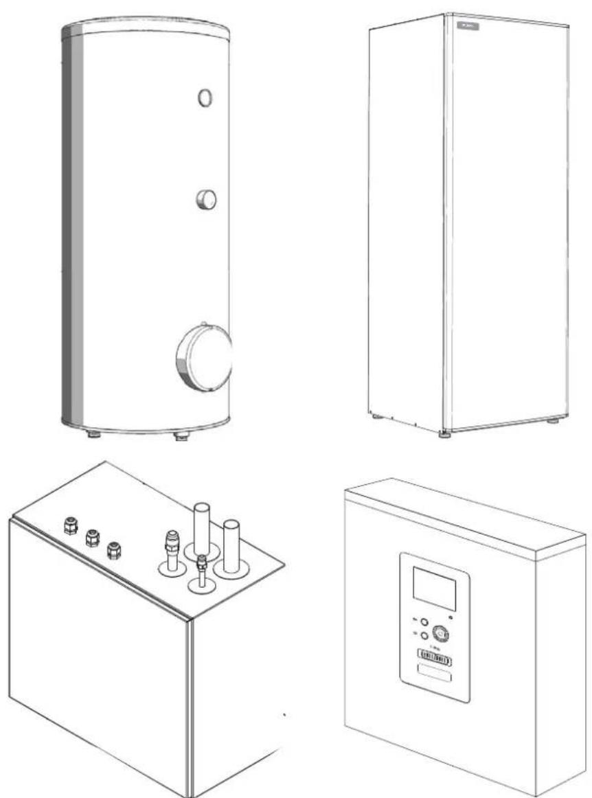
Over view and design
HSB60

Pipe connections
XL1(Red mark) Climate system supply
XL2 (Blue mark) Climate system return
XL14 Connection, gas line
XL13 Connection, liquid line
Valves etc.
EP2 Heat exchanger
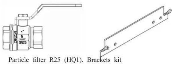
HQ1 Particle filter (supplied)
HZ2 Drying filter
Sensor, thermostats
BP4 Pressure sensor, high pressure
BT3 Temperature sensor, heating medium, return
BT12 Temperature sensor, condenser, supply
BT15 Temperature sensor, fluid pipe
Miscellaneous
UB1 Cable gland
UB2 Cable gland
UB3 Cable gland
Electrical components
AA23 Communication board
AA23-F3 Fuse for external heating cable
AA23-S3 DIP switch, addressing of outdoor unit
AA23-X1 Terminal block, incoming supply, connection of KVR
AA23-X4 Terminal block, communication with indoor module / control module
AA23-X100 Terminal block, communication outdoor module
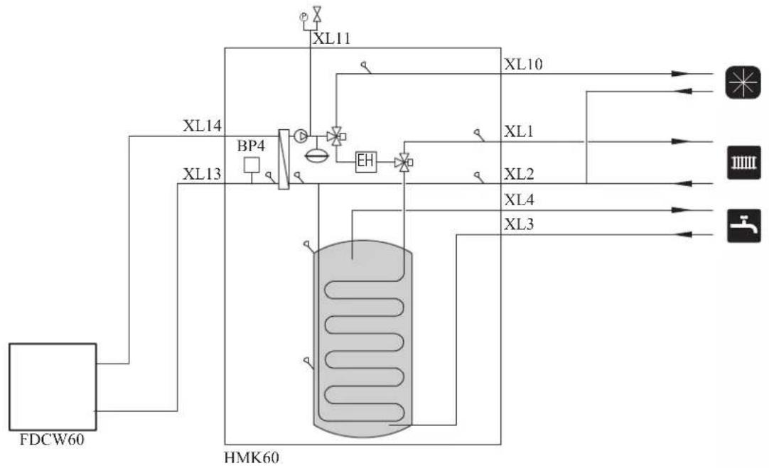
HMK60
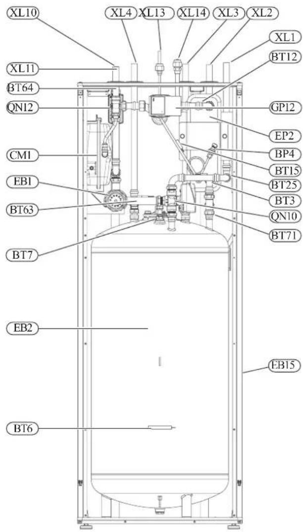
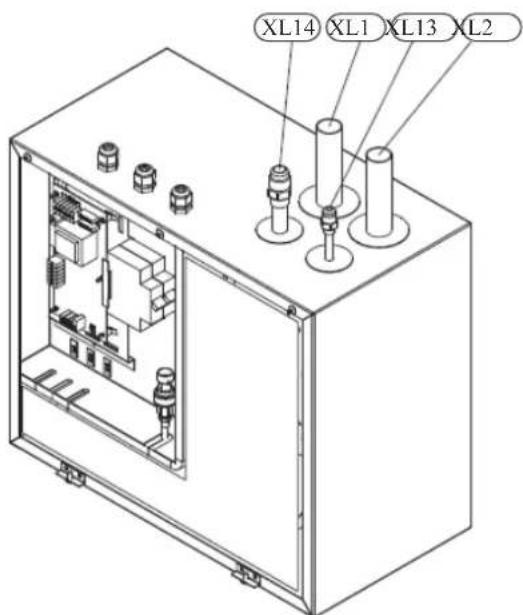
Pipe connections
XL1(→) Connection, heating medium, supply
XL2(→) Connection, heating medium, return
XL3 Connection, cold water
XL4 Connection, hot water
XL10 Connection, cooling
XL11 Connection, safety group, manometer
XL13 Connection, liquid cooling medium
XL14 Connection, gas cooling medium
HVAC elements
CM1 Diaphragm expansion vessel, closed
QN10 Isolation valve, domestic hot water/central heating
QN12 Isolation valve, cooling/heating
GP12 Circulation pump
EP2 Heat exchanger
Sensors
BP4 Pressure sensor, high pressure
BT3 Temperature sensor, heating medium return
BT6 Temperature sensor, hot water loading
BT7 Temperature sensor, top of the hot water heater
BT12 Temperature sensor, condenser outlet
BT15 Temperature sensor, liquid
BT25 Temperature sensor, heating medium supply
BT63 Temperature sensor, heating medium supply downstream the submersible heater
BT64 Temperature sensor, cooling medium supply
BT71 Temperature sensor, heating medium re-turn
Others
EB15 HMK 60
PF3 Serial number
EB2 Domestic hot water tank
PT300


Section of the PT300 storage tanks.
- Upper insulation of the storage tank
- Protective magnesium anode
- Enamelled tank
- Side insulation of the storage tank
- Coil
- Lower insulation of the storage tank
- Adjustable foot
Side view of the PT300 storage tanks.
- Thermometer
- Connector pipe for mounting electric heating unit
- Inspection opening
- Hot water intake connector pipe
- Hot water circulation connector pipe
- Temperature sensor cover
- Coil supply connector pipe
- Connection of return line from the coil
- Cold water supply connector pipe
Transport and storage
Indoor unit and tank unit must be transported and stored vertically in dry conditions.
Supplied components
HSB60 Indoor unit
HMK60 Indoor unit with tank

Safety valve with pressure gauge
RC-HY20/40 Control unit
Outside sensor

Room sensor (RC-HY40 only)
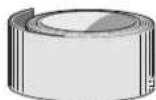
Insulation tape
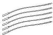
Temperature sensor
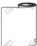
Aluminium tape
Cable ties
Heating pipe paste
Current sensor (RC-HY40 only)
Assembly
It is recommended that indoor unit is installed in a room with existing floor drainage, most suitably in a utility room or boiler room.
■ For indoor unit and control unit, the mounting surface must be fl rm, fl at and vertical, preferably a concrete wall.
■ Indoor unit with tank and tank unit must be set on a solid waterproof base that would keep the weight of the unit. The height-adjusting legs allow for levelling and stable setting.
HMK60
PT300

■ For indoor unit with tank, floor drain port is required to connect drain hose in case cooling function is used.
■ Install indoor unit with its back to an outside wall, ideally in a room where noise does not matter. If this is not possible, avoid placing it against a wall behind a bedroom or other room where noise may be a problem.
■ Route pipes so they are not fixed to an internal wall that backs on to a bedroom or living room.
■ Install indoor unit with tank, tank unit and its pipings to indoor unit indoors in order to avoid icing.
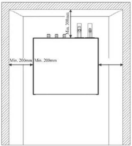
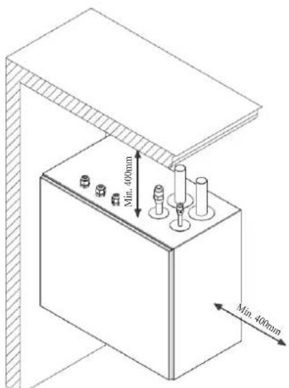
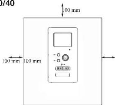
■ Ensure free space described in the following figures for future maintenance.
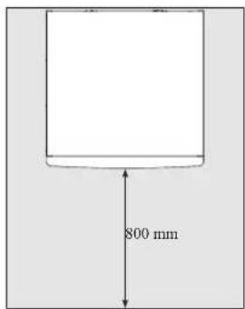
HSB60
Recommendation for positioning on wall
Recommendation for positioning in corner
*Min 800mm is required in front
HMK60
IMPORTANT
For HMK60, leave 10 – 25 mm free space between the indoor module and the back wall for cables and piping.
PT300
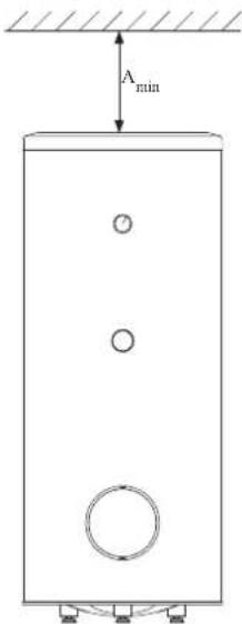
A _min is required on top to replace anode bar, and 500 mm is required in front to replace immersion heater if equipped.
| Application | Connector pipe dia. | Type of anode A | min |
| PT300 | 1" Chainø | 26 × 8 | 150 mm |
| 34 "Titanium | anode 200 mm |
RC-HY20/40
Hanging indoor unit
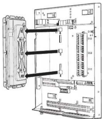
It is recommended that the split box is installed in a room with existing floor drainage, most suitably in a utility room or boiler room.
- The bracket for the split box is mounted to the wall by use of appropriate screws.
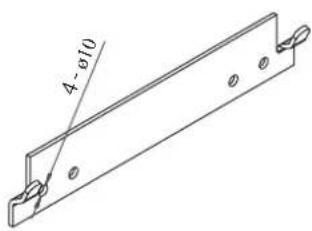
- Insert HSB60 in the bracket mounted to the wall.

natural_image
Technical line drawing of an electrical enclosure with multiple cylindrical components and a door handle (no text or symbols)NOTE
Indoor unit weigh 16 kg excluding water inside.
Hanging control unit
Use all mounting points and install control unit upright against a fl at wall. Make sure whole back surface faces the wall.

Dimensioning expansion vessel
The expansion vessel volume must be at least 5% of total water volume in the circulation system.
HMK60 is equipped with an expansion vessel with a volume of 10 liters.
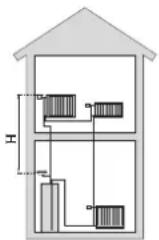
Initial pressure and max height difference
Recommended maximum height difference between expansion vessel and the highest point in the system is 5m.
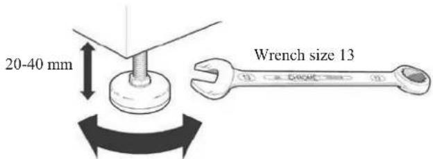
The initial pressure of the pressure expansion vessel must be dimensioned according to the maximum height (H) between the vessel and the highest positioned radiator, see figure. An initial pressure of 0.5 bar (5 mvp) means a maximum permitted height difference of 5 m.
If the standard initial pressure in the pressure vessel is not high enough it can be increased by filling via the valve in the expansion vessel. The expansion vessel's standard initial pressure must be entered in the check list on User's manual.
Any change in the initial pressure affects the ability of the expansion vessel to handle the expansion of the water.
Consult local distributor in case height difference exceeds 5m.
Recommended installation order
- Hang indoor unit and control unit to appropriate position and connect indoor unit and tank unit.
- Connect indoor unit to climate system, cold and hot water lines as well as any external heat sources. See page 14, 15. Also see docking descriptions on page 26-28 and further on.
- Install refrigerant pipes according to the description on the Installation manual for outdoor unit.
- Connect current limiter, any centralised load control and external contacts as well as the cable between indoor unit and outdoor unit.
- Connect incoming electricity to indoor unit and/or outdoor unit. See page 34-36.
- Follow the commissioning instructions on page 37-55.
Pipe installation
General
Pipe installation must be carried out in accordance with current norms and directives.
A following table shows plumbing necessary for each product.
| Refrigerant Plumbing | ||
| HSB Necessary Necessary | ||
| HMK Necessary Necessary | ||
| PT — Necessary | ||
| PC-HY — — | ||
This heat pump system is designed for low or medium temperature heating system. It is recommended water temperature must not exceed 55^ on supply and 45^ on
return at lowest design outdoor temperature (DOT) though indoor unit can operate with a return temperature of up to 65°C and an outgoing temperature from the unit of 65°C.
Indoor unit is not equipped with shut off valves; these must be installed outside the heat pump to facilitate any future servicing.
Indoor unit can be connected to the radiator system, floor heating system and/or fan convectors.
Safety valve is not equipped with in indoor unit. Make sure to install safety valve in the circuit.
Installation diagram
FDCW60VNX-A outdoor unit provides heat for space heating and domestic hot water using free energy in the outdoor air within the range of low temperature up to -20°C. Connection is different according to the type of indoor unit (see below figures). The system is controlled by RC-HY20 or RC-HY40 control unit.
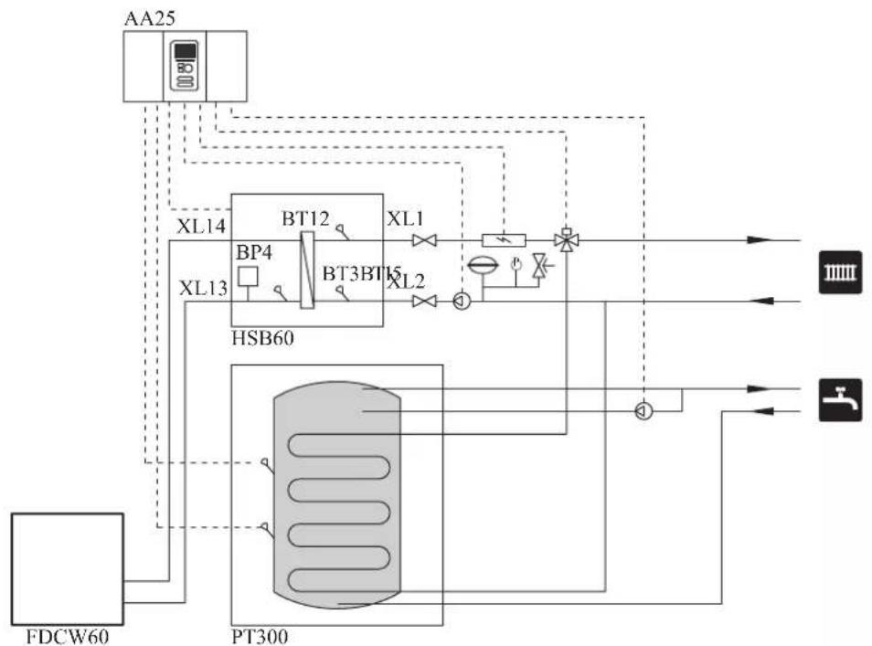
HSB60
HSB60 indoor unit is equipped with plate heat exchanger. It needs to install expansion vessel, shut-off valves, safety valve, electric heater and circulation pump to make a complete heating system. In case domestic hot water is required, 3 way valve and tank is also necessary.
flowchart
graph TD
    A["AA25"] --> B["XL14"]
    A --> C["XL13"]
    B --> D["BT12"]
    C --> E["BT3BT15"]
    D --> F["XL1"]
    E --> G["XL2"]
    F --> H["PT300"]
    G --> H
    H --> I["①"]
    I --> J["HL1"]
    I --> K["HL2"]
    L["FDCW60"] --> M["PT300"]
    M --> N["HL1"]
    M --> O["HL2"]
    P["HL1"] --> Q["PT300"]
    R["HL2"] --> S["PT300"]
    T["HL1"] --> U["PT300"]
    V["HL2"] --> W["PT300"]
    X["HL1"] --> Y["PT300"]
    Z["HL2"] --> AA["PT300"]
HMK60
HMK60 indoor unit is equipped with coil water heater, expansion vessel, safety valve, electric heater, plate heat exchanger, sensors and gauge, and circulation pump.
flowchart
graph TD
    A["FDCW60"] --> B["HP"]
    B --> C["XL13"]
    C --> D["BP4"]
    D --> E["XL14"]
    E --> F["XL11"]
    F --> G["XL10"]
    G --> H["XL2"]
    H --> I["XL4"]
    I --> J["XL3"]
    J --> K["Output 1"]
    J --> L["Output 2"]
    J --> M["Output 3"]
| Symbol | Meaning Symbol Meaning | ||
| ↑ | Vent | ◎ | Manometer |
| ☒ | Cut-off valve Circulation pump ☑ | ||
| + | Water tap Particulate filter | ☐ | |
| ☒ | Non-return valve Compressor | ∅ | |
| ☒ | Balancing valve Heat exchanger | / | |
| ☒ | Three-way valve Cooling |  | |
| ☒ | Safety valve Central heating sy  |  | |
| T | Thermometer Domestic hot wa | ||
| q | Temperature sensor |  | Heating systems Floor heating |
| ∅ | Diaphragm expansion vessel |  | Cooling system |
System requirements
The minimum water volume in the climate system is subject to the values in the table below. If it is not fulfilled, volume vessel must be installed.
For more options, see the docking description on Page 24. (liter)
| With underf loor cooling application | Without underf loor cooling application | |
| HSB60, HMK60, FDCW60VNX-A | 50 20 |
Overflow valve
NOTE
A free flow is required for all docking options, which means that an overflow valve must be installed. The circulation pump may become damaged.
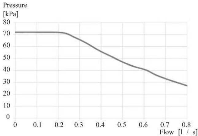
Pump capacity diagram
HSB60
HSB60 is not equipped with circulation pump.
This graph shows the characteristic of CPD11-25/55.
line
| Flow [l / s] | Pressure [kPa] | | ------------ | -------------- | | 0.0 | 70 | | 0.1 | 70 | | 0.2 | 70 | | 0.3 | 65 | | 0.4 | 55 | | 0.5 | 45 | | 0.6 | 40 | | 0.7 | 35 | | 0.8 | 25 |HMK60
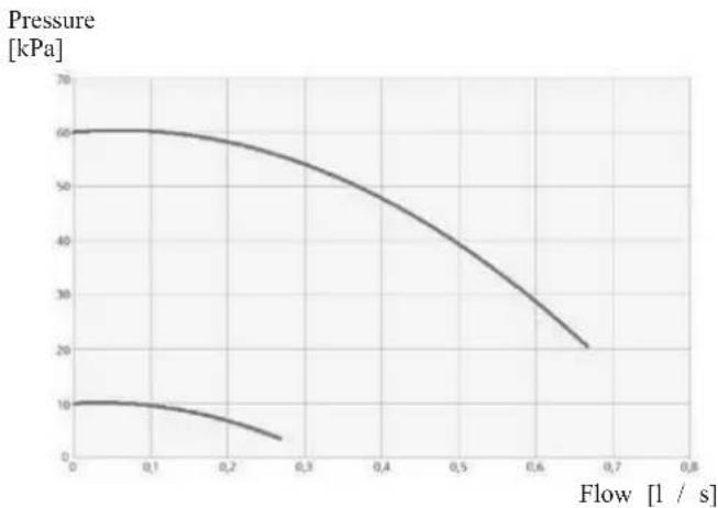
line
| Flow [1 / s] | Pressure [kPa] | | ------------ | -------------- | | 0.0 | 60 | | 0.1 | 60 | | 0.2 | 55 | | 0.3 | 50 | | 0.4 | 45 | | 0.5 | 40 | | 0.6 | 30 | | 0.7 | 20 |Pressure drop in indoor unit
HSB60

line
| Flow Rate [l / s] | HSB60, 140HSB10Flow [kPa] | | ----------------- | ------------------------- | | 0.0 | 0 | | 0.1 | ~1 | | 0.2 | ~3 | | 0.3 | ~5 | | 0.4 | ~8 | | 0.5 | ~12 | | 0.6 | ~18 | | 0.7 | ~25 | | 0.8 | ~30 |HMK60
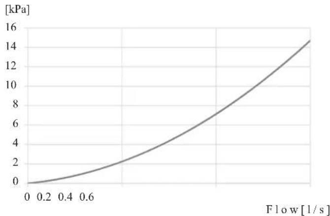
line
| Flow [l/s] | Pressure [kPa] | | ---------- | -------------- | | 0.0 | 0.0 | | 0.2 | 0.5 | | 0.4 | 1.5 | | 0.6 | 3.0 | | 0.8 | 6.0 | | 1.0 | 9.0 | | 1.2 | 12.0 | | 1.4 | 14.5 |Connection of extra circulation pump
When connecting extra circulation pumps, requirements for pressure, maximum flow etc must be met. See page 27 for location.
NOTE
Non-return valve must be installed in case extra circulation pump is used. See page 27 for the position.
The circulation pump may become damaged.
Dimensions and pipe connections
HSB60

Pipe connections
XL1 (Red mark) Climate system, flow 28 mm
XL2 (Blue mark) Climate system, return 28 mm
XL14 Gas line refrigerant, fl are 12
XL13 Liquid line refrigerant, fl are 14
HMK60
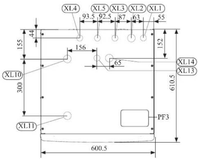
Pipe connections
XL1(→) Connection, Heating medium supply 22 mm
XL2(→) Connection, Heating medium return 22 mm
XL3 Connection, cold water 22 mm
XL4 Connection, hot water 22 mm
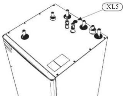
XL5 Connection, circulation 015 mm
XL13 Connection, liquid cooling medium 14
XL14 Connection, gas cooling medium 12
XL10 Connection, cooling 22 mm
XL11 Connection, safety valve ø22 mm, manometer
Other information
PF3 Serial number plate
PT300
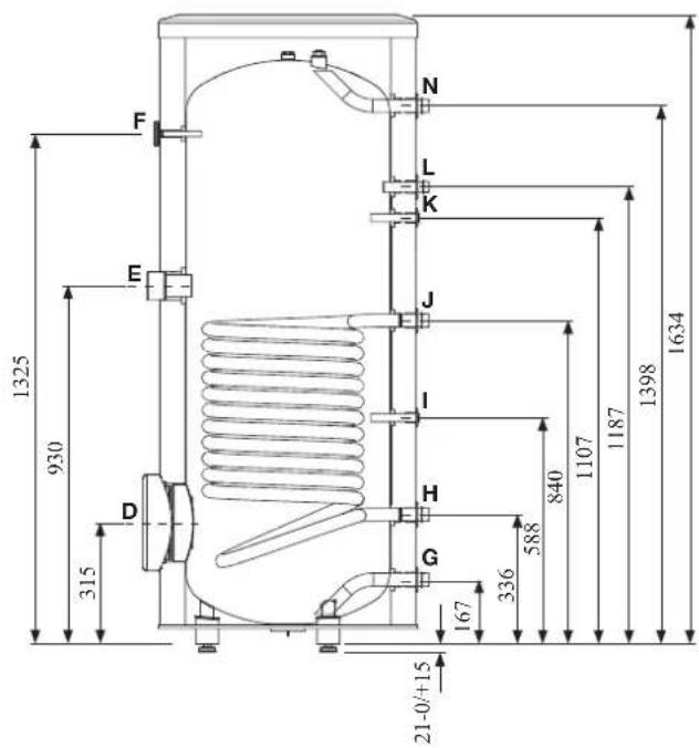
| Connection | U/m | PT300 | |
| D | Inspection opening mm 120 | ||
| E | Heating unit connection inch | 112 "Female | |
| F | Thermometer enclosure mm | 10 Female | |
| N | Hot water outlet inch 1 "Male | ||
| L | Hot water circulation inch 34 "Male | ||
| K | Temp. sensor enclosure (BT7) | mm 16 Female | |
| J | Coil supply inch 1 "Male | ||
| I | Temp. sensor enclosure (BT6) | mm 16 Female | |
| H | Return from coil inch 1 "Male | ||
| G | Cold water input | inch 1 "Male | |
Water circuit
Connection to heating system
Connect XL1 to supply line and X2 to return line from heating system.
■ All required safety devices and shut-off valves must be installed as close to the indoor unit as possible.
■ Install bleed valves where necessary, highest point of the water system in usual case.
■ When connecting to a system with thermostats on all radiators, install an overflow valve or remove some of the thermostats to ensure sufficient flow.
■ See section Dockings on page 25 for outline diagram.
■ Install a safety valve with manometer on heating circuit and hot water circuit. (FL2)
For HSB60 install a safety valve for heating circuit on the water pipe returning to indoor unit since it doesn't have port for FL2.
The entire length of the overflow water pipe from the safety valves must be inclined to prevent water pockets and must also be frost proof.
■ The end of overflow water pipe from the safety valves must be left open to the atmosphere. The water may drip from the pipe.
HSB60
Install safety valve as close to XL2 as possible.
HMK60

Install safety valve FL2 on XL11.
Connection to hot water heater
For HSB60 indoor unit, it is necessary to connect PT300 tank unit applying 3 way valve in order to use domestic hot water function.
For HMK60 indoor unit, 180L tank unit is integrated in indoor unit.
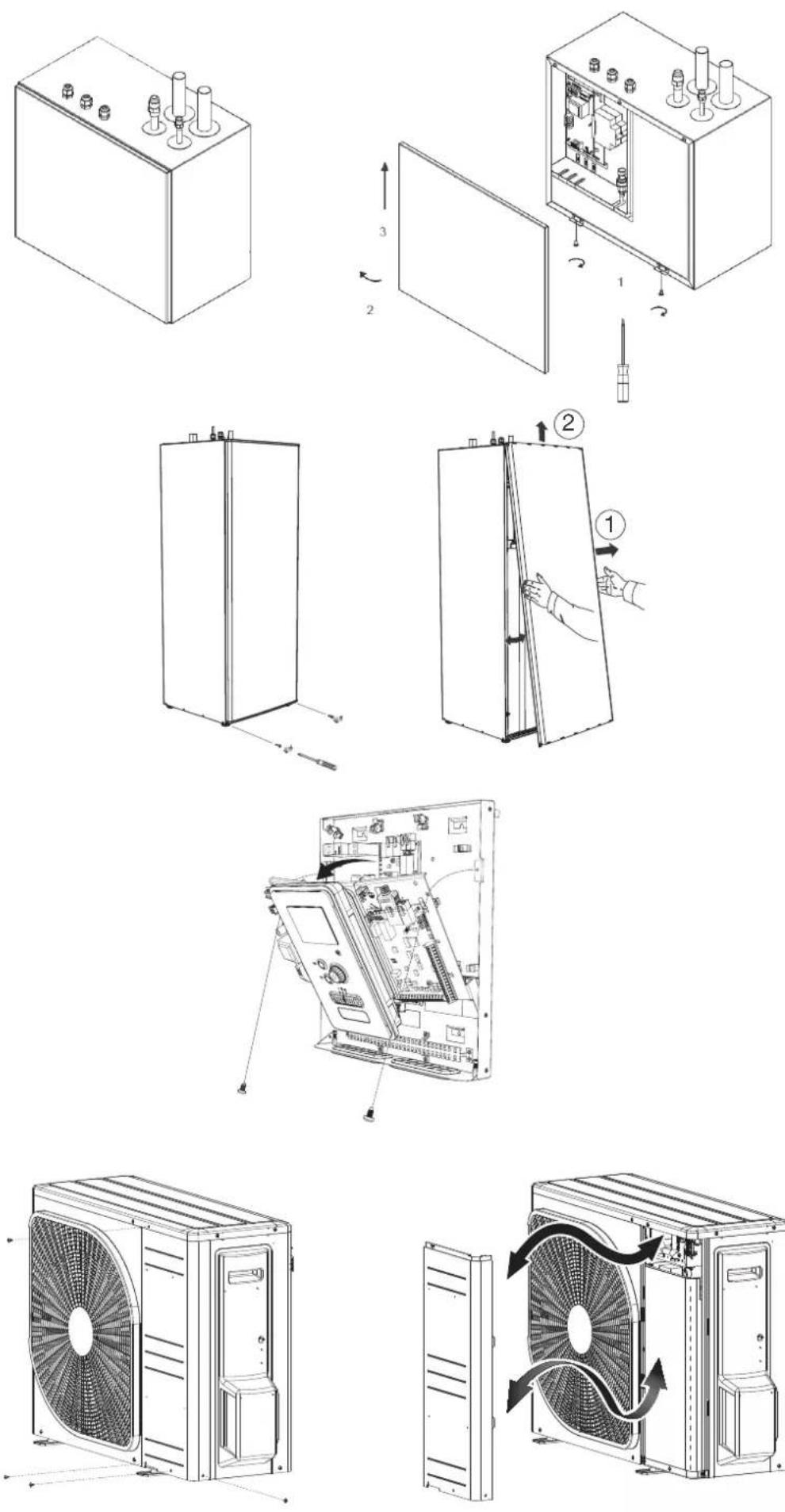
Housing disassembly of tank unit
Removable housing with thermal insulation facilitates transport and installation of the storage tank. Disassembly the housing in the following order (see below figure):
- Remove the Temperature gauge, plug of the heating element connector pipe and blanking plate of the inspection opening.
2 Remove the upper cover of the housing together with thermal insulation. - Remove the plugs from the connector pipes and black bushings.
- Remove the fixing screws and the strip connecting the housing jacket.
- Remove the jacket surrounding the tank (housing jacket.)
- Remove the four-piece thermal insulation.
After the installation of the storage tank in its final location, reinstall the removed components in the reverse order.
Housing and thermal insulation disassembly

Connecting hot water tank to indoor unit
CAUTION
Installation and commissioning of the storage tank shall only be done by appropriately qualified installer. The installer should inform the user of the functions of the product and provide the necessary in formation on its safe use.
Information
We recommend installing a strainer in order to protect the pumps, check valve and the components of the heating system.
■ Tank and its pipings to indoor unit must be installed indoors where the temperature wouldn't drop below 15^ C in order to prevent pipings from icing.
■ Maximum piping length between indoor unit and tank is 10 m.
■ Tank unit should be placed on firm, preferably a concrete floor or foundation.
■ Tank unit can be aligned using the adjustable feet.
■ Protection against overpressure shall be made in accordance with the relevant regulations.
■ Connect the heating system according to the installation diagram (see figure).
Installation diagram of the PT storage tank with one coil.

Connecting hot water tank to water main
■ Install a mixing valve if the temperature exceeds 60^ C.
■ It is recommended to install a thermostatic mixing valve for stable temperature hot water supply.
■ Connect the storage tank to the water supply system of water pressure at least 1 bar and max 10 bar. Install a pressure reducer if the pressure at the cold water inlet to the tank is higher than allowed.
■ Install a safety valve which have a maximum 10.0 bar opening pressure on the incoming domestic water line according to outline diagram in order to protect the storage tank against overpressure. Pressure increases during heating the water.
■ During heating the water, small and temporary water flow from the safety valve can occur, which indicates that the pressure has increased above the rated value, which triggered the valve. This may in no way be prevented.
■ Safety valve drain line should be installed with a decline, in an environment free of freezing and remain open to the atmosphere. The manufacturer is not responsible for flooding the room through the safety valve.
■ Blocked safety valve can cause equipment failure. Drain the outflow from the safety valve to the sewerage or drain grate.
■ See section Dockings on page 25 for outline diagram.
■ Connect the water supply system according to the installation diagram.
Installation diagram of the PT storage tank with one coil.

flowchart
graph TD
    A["1"] --> B["2"]
    B --> C["7"]
    C --> D["6"]
    D --> E["2"]
    E --> F["DHW"]
    F --> G["2"]
    G --> H["3"]
    H --> I["4"]
    I --> J["5"]
    J --> K["8"]
    K --> L["to sewerage"]
    K --> M["water supply system"]
    N["hot water circulation (optional)"] --> E
- PT storage tank
- Cut-off valve
- Safety valve
- Drain valve
- Pressure reducer (option, if the pressure in the system exceeds the allowable value)
- Strainer
- Hot water circulating pump
- Hot water expansion vessel
Information
In order to minimize the flow of water from the safety valve associated with the thermal expansion of the liquid, it is advisable to install a suitable expansion vessel at the cold water connection (see item 8.)
CAUTION
Installation of the appropriate safety valve in the cold water supply line protecting the unit against overpressure is mandatory!
CAUTION
Installation of necking of any kind (such as reducers, dirt pockets, etc.) and cut-off valves between the storage tank and the safety valve is not allowed. Only a T-pipe with a drain valve and a T-pipe with an expansion vessel may be installed in these line sections.
CAUTION
Never block the safety valve or drain line. This can cause a dangerous overpressure in the storage tank.
CAUTION
When heating water, slight, temporary discharge from the safety valve can occur. This is a correct safety valve function. Any attempt to interfere in its operati on can lead to the danger and destruction of the storage tank.
CAUTION
Never use the equipment with clogged safety valves.
Connection
After the installation and levelling the tank, follow the procedure below (for the connector pipe symbols, refer to page 19):
- Remove protecting plugs from the connector pipes
- Connect the hot water intake line (N).
- Connect the cold water supply line together with the required safety valves (G).
- If the system has the hot water circulation system, connect it to the connector pipe (L). Otherwise, plug the pipe.
- Connect the supply (J) and return (H) of the heating medium to the coil.
CAUTION
If there is an electric heating module installed in the storage tank, fill the tank with water before connecting it to the electrical installation.
Hot water circulation circuit
Hot water circulation function is available for HMK60 and PT300.
HMK60

flowchart
graph TD
    A["压力传感器"] --> B["阀门"]
    B --> C["气压容器"]
    C --> D["控制阀"]
    D --> E["阀门"]
    E --> F["压力传感器"]
    F --> G["阀门"]
    G --> H["压力传感器"]
    H --> I["阀门"]
    I --> J["压力传感器"]
    J --> K["阀门"]
    K --> L["压力传感器"]
    L --> M["阀门"]
    M --> N["压力传感器"]
    N --> O["阀门"]
    O --> P["压力传感器"]
    P --> Q["阀门"]
    Q --> R["压力传感器"]
    R --> S["阀门"]
    S --> T["压力传感器"]
    T --> U["阀门"]
    U --> V["压力传感器"]
    V --> W["阀门"]
    W --> X["压力传感器"]
    X --> Y["阀门"]
To connect the circulation:
- Remove the XL5 plug from the top of the housing.
- Remove the front panel, then slide the control panel down to access the hydraulic connections.
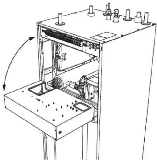
natural_image
Technical line drawing of a mechanical assembly with no visible text or symbols- Remove the plug from the circulation pipe (XL5).

-
Install the elbow, facing the rear housing, on the circulation pipe.
-
Connect the pipe to the elbow, with the dimensions shown in the figure below, leading pipe in the top of the housing, in place of the XL5 plug. Mount the pipe insulation.
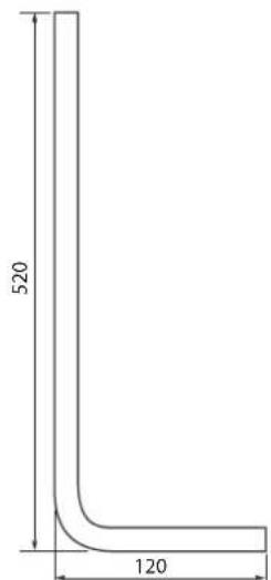
Circulation pipe dimensions (*)

Elbow 15x15 (*)
-
At the outlet of the circulation tube, install the circulation pump and then connect its control to the RC-HY (Chapter 5 Electrical connection).
-
Install the control panel and the front panel.
(*) Prepared on site.
PT300
If the system has the hot water circulation system, connect it to the port L (see page 19).
Then install the Cut-off valves, circulation pump and strainer.
Connection of external heat source
External heat source, e.g. a gas or oil boiler or electric heater, can be connected on supply line of heating system (XL1).
Refrigerant circuit
Connecting refrigerant pipes
See Installation manual for outdoor unit.
Piping insulation
Install insulation on all piping in order to avoid condensation during cooling operation.
It is also strongly recommended to insulate piping for heating only application in order to avoid getting burned or reducing the heating capacity.
The thickness of the insulation should be 20mm where the relative humidity exceeds 70%.
Drain connection
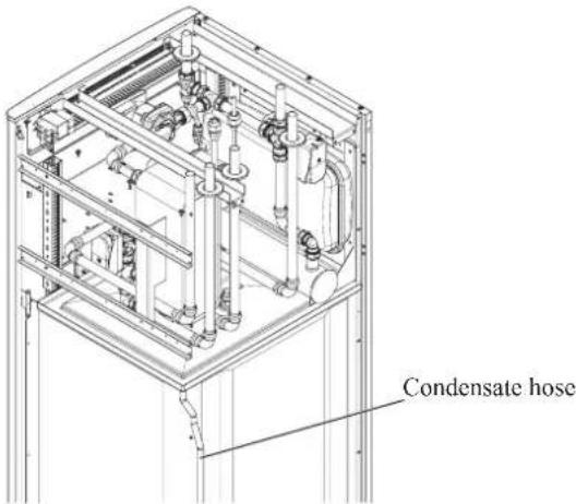
HMK 60 is equipped with a condensate hose in the heat exchanger section. The hose drains all condensate away from the device to minimize the risk of damage. If necessary, the hose can be extended.
Dockings
General
Installation requirements
Hydrolution can be connected in several different ways, some of which are shown on the following pages.
| HMK60HSB60 | ||
| FDCW60VNX-A | ||
| Max pressure, climate system | 0.25 MPa (2.5 Bar) | |
| Highest recommended supply/return temperature | 55/45°C | |
| Max temperature, climate system | 65 °C | |
| Max temperature in indoor unit | 65 °C | |
| Max temperature from external heat source | 65 °C | |
| Max supply temperature with compressor at outdoor temp -15°C | 58 °C | |
| Min supply temp. cooling | 7 °C | |
| Max supply temp. cooling | 25 °C | |
| Min volume, climate system during heating, cooling | 20 L | |
| Min volume, climate system during underfloor cooling | 50 L | |
| Max flow, climate system | 0.29 L/s | |
| Min flow, climate system, at 100% circulation pump speed | 0.19 L/s | |
| Min flow, climate system | 0.09 L/s | |
| Nominal system flow heating (ΔT=5K) | 0.29 L/s (6kW, 7/45°C) | |
| Nominal system flow cooling (ΔT=5K) | 0.28 L/s (5.8kW, 35/7°C) | |
External circulation pump must be used when the pressure drop in the system is greater than the available external pressure. In such cases, a bypass line with non-return valve must be installed.
Use an overflow valve if system flow cannot be guaranteed.
Symbol key
| MeaningSymbol | |
| ↑ | Venting valve |
| ☒ | Shut-off valve |
| ☒ | Non-return valve |
| ☒ | Control valve |
| ☒ | Safety valve |
| ♀ | Temperature sensor |
| Expansion vessel | |
| ◎ | Pressure gauge |
| ◎ | Circulation pump |
| Shunt / shuttle valve | |
| ◎ | Fan |
Docking alternatives
Heating system can be constructed in several different ways combining indoor unit, tank, control unit and other accessories.
For further option information, see page 84.
In the system example shown on the following page, heating, hot water as well as cooling operation are available.
Additional heating is helpful on the cold day of the year as the energy from the air is reduced. It is also recommended as back-up in case the heat pump operation is blocked for any reason (e.g. ambient temperature exceeds the operation limit of heat pump).
NOTE
The heating medium side and the hot water side must be fitted with the necessary safety equipment in accordance with the applicable regulations.
This is the outline diagram. Actual installations must be planned according to applicable standards.
Explanation
AA25 Controller
BT1 Outdoor sensor 1)
BT6 Temperature sensor, hotwater charging 1)
BT7 Temperature sensor, hot water top 1)
BT25 Temperature sensor, external supply line 1)
BT50 Room sensor
BT63 Temperature sensor, external supply line after electric heater
BT71 Temperature sensor, external return line 1)
GP10 Circulation pump, Heating medium
QN10 Reversing valve, Hot water/Heating medium 2)
EB1 Additional heat
EB1 Immersion heater
KA1 Auxiliary relay/Contactor 2)
EB101 Heat pump system
BP4 Pressure sensor, condensor 3)
BT3 Temperature sensor, return line 3)
BT12 Temperature sensor, condenser supply line 3)
BT15 Temperature sensor, fluid pipe 3)
EB101 Heat pump
FL10 Safety valve
GP12 Charge pump ^2)
HQ1 Particle filter 3)
QM1 Drain valve, Heating medium
QM31 Shut-off valve, Heating medium, Flow
QM32 Shut off valve, Heating medium, Return
QM43 Shut-off valve
EQ1 Cooling system
BT64 Temperature sensor, cooling supply line 2)
CP6 Single jacket accumulator tank, cooling
GP13 Circulation pump, cooling
QN12 Reversing valve, Cooling/Heating ^2)
Miscellaneous
CM1 Expansion vessel closed, Heating medium
CP5 Buffer vessel
CP10 Accumulator tank with hotwater heating
EB20 Immersion heater
FL2 Safety valve, Heating medium
KA1 Auxiliary relay/Contactor
RN10 Trim valve
1) Included in and supplied with controller
2) Included in and supplied with accessory
3) Included in indoor unit
Installation with indoor unit HSB60, tank PT300, controller RC-HY20/40 with step controlled additional heat before reversing valve for hot water and cooling function (4 pipe system)
flowchart
graph TD
    A["EQ1"] --> B["-AA25"]
    B --> C["CP6-CP6"]
    C --> D["-BP13"]
    D --> E["-BT64"]
    E --> F["--EA25"]
    F --> G["--BA25"]
    G --> H["--BA1"]
    H --> I["--EB1"]
    I --> J["--BA25-BT7"]
    J --> K["--QA25-BT6"]
    K --> L["--RN10"]
    L --> M["--FL2"]
    M --> N["--CM1"]
    N --> O["--CP10"]
    O --> P["--AA25-BT7"]
    P --> Q["--QA25-BT6"]
    Q --> R["--EQ1-QN12"]
    R --> S["--GP12"]
    S --> T["HQ1"]
    T --> U["--QM43"]
    U --> V["--AZ101"]
    V --> W["--EZ101"]
    W --> X["--XL14"]
    X --> Y["--XL13"]
    Y --> Z["--EZ102"]
    Z --> AA["--QB15"]
    AA --> AB["--QB2"]
    AB --> AC["--QB3"]
    AC --> AD["--QB4"]
    AD --> AE["--QB5"]
    AE --> AF["--QB6"]
    AF --> AG["--QB7"]
    AG --> AH["--QB8"]
    AH --> AI["--QB9"]
    AI --> AJ["--QB10"]
NOTE
Not all components are shown in this outline diagram.
Controller (AA25) starts and stops the heat pump (EB101) to meet the heating and hot water demand.
At simultaneous heating and hot water demand, the reversing valve (AA25-QN10) switches periodically between the climate system and the water heater/accumulator tank (CP10). When the hot water heater/accumulator tank is fully charged, the reversing valve switches to the climate system.
Additional heat (EB1) is turned on automatically when the heating demand exceeds the heat pump capacity. This is used for both heating and charging hot water.
The additional heat can also be used for water heater when a higher temperature is required than the heat pump can produce.
During cooling operation, the reversing valve (EQ1-QN12) switches to the cooling system (EQ1). If several simultaneous demands occur while there is a cooling demand, the system reacts differently. In the event of a hot water demand, the reversing valve switches back and hot water is produced until the demand is fulfilled. In the event of a heating demand, the reversing valve switches periodically between cooling and heating. If the cooling demand is met, the reversing valve switches back to basic mode (heating/hot water).
Indoor unit HSB60, tank PT300, controller RC-HY20/40 with step controlled additional heat after reversing valve for hot water and cooling function (4 pipe system)

flowchart
graph TD
    A["EQ1"] --> B["-AA25"]
    B --> C["CP6-CP6"]
    C --> D["-GP13"]
    D --> E["BT64"]
    E --> F["AA25"]
    F --> G["-EA25-QN10"]
    G --> H["CP5"]
    H --> I["-EB1"]
    I --> J["KA1"]
    J --> K["-EB1"]
    K --> L["QA25"]
    L --> M["-BP10"]
    M --> N["BT25"]
    N --> O["-BT71"]
    O --> P["III"]
    F --> Q["AA25-BT1"]
    F --> R["AA25-BT50"]
    Q --> S["FQ1-QN12"]
    R --> S
    S --> T["-RN10"]
    T --> U["FL2"]
    U --> V["-CM1"]
    V --> W["CP10"]
    W --> X["AA25-BT7"]
    X --> Y["AA25-BT6"]
    Y --> Z["-KA1"]
    Z --> AA["-EB20"]
    AA --> AB["FI2"]
    AB --> AC["-CN1"]
    AC --> AD["-EB101"]
    AD --> AE["EB101"]
    AF["EZ101"] --> AG["-XL14"]
    AG --> AH["-XL13"]
    AH --> AI["EZ102"]
    AI --> AJ["-BM31"]
    AJ --> AK["-BM32"]
    AK --> AL["-BM1"]
    AL --> AM["-FL10"]
    AM --> AN["-QM1"]
    AN --> AO["-BM43"]
    AO --> AP["-GP12"]
    AP --> AQ["HQ1"]
    AQ --> AR["-QM31"]
    AR --> AS["-BM32"]
    AS --> AT["-BM1"]
    AT --> AU["-FL10"]
    AU --> AV["-QM1"]
NOTE
Not all components are shown in this outline diagram.
This installations alternative is suitable for more complex installations with a focus on comfort.
Controller (AA25) starts and stops the heat pump (EB101) to meet the heating and hot water demand of the installation.
At simultaneous heating and hot water demand the reversing valve (AA25-QN10) switches periodically between the climate system and the water heater/accumulator tank (CP10). When the hot water heater/accumulator tank is fully charged, the reversing valve switches to the climate system.
Additional heat (EB1) is turned on, automatically when the heating demand exceeds the heat pump capacity.
Immersion heater (EB20) in the water heater/accumulator tank is used during the time to produce hot water if the heat pump is used for heating at the same time.
The immersion heater (EB20) can also be used if a higher temperature of hot water is required than the heat pump can produce.
During cooling operation, the reversing valve (EQ1-QN12) switches to the cooling system (EQ1). If several simultaneous demands occur while there is a cooling demand, the system reacts differently. In the event of a hot water demand, the reversing valve switches back and hot water is produced until the demand is fulfilled. In the event of a heating demand, the reversing valve switches periodically between cooling and heating. If the cooling demand is met, the reversing valve switches back to basic mode (heating/hot water).
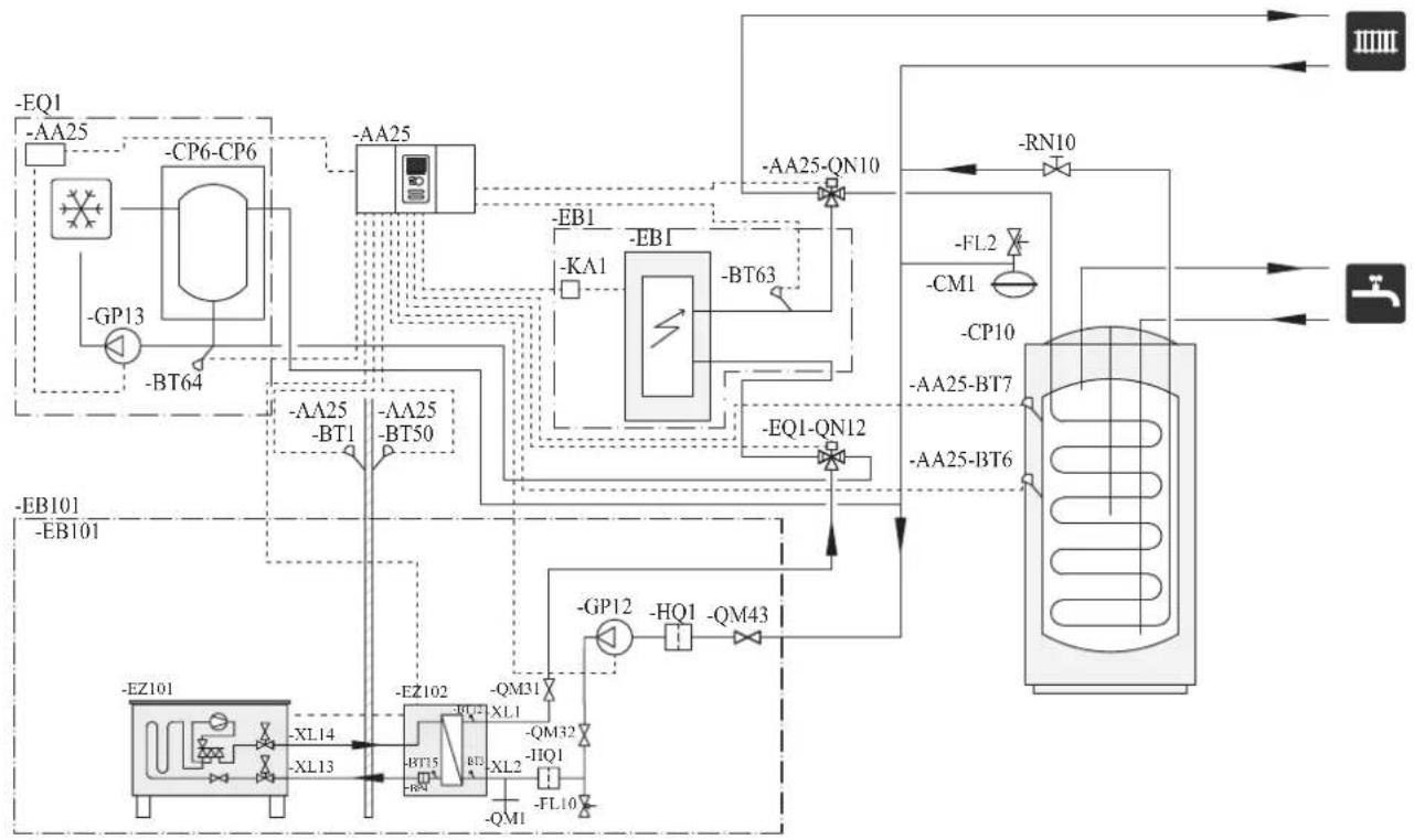
Installation with indoor unit HMK60 for hot water and cooling function (4 pipe system)

flowchart
graph TD
    A["AA25"] --> B["XL14"]
    A --> C["XL13"]
    B --> D["XL10"]
    C --> E["XL14"]
    D --> F["-BT64"]
    D --> G["-GP12"]
    D --> H["-BM1"]
    E --> I["-BT12"]
    E --> J["-BM4"]
    E --> K["-BM7"]
    E --> L["-BM9"]
    E --> M["-BM10"]
    E --> N["-BM11"]
    E --> O["-BM12"]
    E --> P["-BM13"]
    E --> Q["-BM14"]
    E --> R["-BM15"]
    E --> S["-BM16"]
    E --> T["-BM17"]
    E --> U["-BM18"]
    E --> V["-BM19"]
    E --> W["-BM20"]
    E --> X["-BM21"]
    E --> Y["-BM22"]
    E --> Z["-BM23"]
    E --> AA["-BM24"]
    E --> AB["-BM25"]
Controller (AA25) starts and stops the heat pump (EB101) to meet the heating and hot water demand. At simultaneous heating and hot water demand, the reversing valve (QN10) swithes periodically between the climate system and the hot water heater. When the hot water heater is fully charged, the reversing valve swithes to the climate system.
Additional heat (EB1) is turned on automatically when the heating demand exceeds the heat pump capacity. This is used for both heating and charging water heater.
The additional heat can also be used for water heater when a higher temperature is required than the heat pump can produce.
Cooling is controlled by the sensor BT64, and the reversing valve (QN12) swithes to the cooling system. If several simultaneous demands occur while there is a cooling demands, the system reacts differently. In the event of a hot water demand, the reversing valve switches back and hot water is produced until the demand is fulfilled. In the event of heating demand, the reversing valve switches periodically between cooling and heating. If the cooling demand is met, the reversing valve switches back to basic mode (heating/hot water).
Electrical installation
General
Indoor unit must be installed via an isolator switch in accordance with the local codes and regulations.
For HMK60, electrical equipments, except outdoor air sensor, room sensor, current transformers and outdoor unit has been connected at the factory.
■ Disconnect the indoor unit, outdoor unit and control unit before insulation testing of the house wiring.
■ If the building is equipped with an earth-fault breaker, Hydrolution should be equipped with a separate one.
■ For the electrical wiring diagram, see page 85.
■ Do not lay communication, sensor or signal cables for external connection close to high voltage lines.
■ Minimum cross section of communication, sensor or signal cables for external connection must be 0.5mm^2 up to 50 m, for example EKKX, LiYY or equivalent.
■ Use screened three core cable for communication between controller (RC-HY20/40) and indoor unit (HSB60/HMK60).
■ When laying cables into indoor units and controllers, be sure to route the cable grommet (UB1 AND UB2).
■ Be careful to route cables not to be damaged by metal edge or trapped by panels.
■ Outdoor unit is equipped with a single phase compressor. This means that phase L3 is loaded with up to 15 A during compressor operation.
NOTE
Electrical installation and service must be carried out under the supervision of a qualified electrician.
Turn off the circuit breaker before carrying out any servicing.
Electrical installation and wiring must be carried out in accordance with the stipulations in force.
Make sure to turn off the power supply during installation.
NOTE
Do not turn on the power on control until the boiler is filled with water.
The circulation pump and immersion heater may become damaged.
NOTE
If the power supply cable is damaged, only authorised person may replace it to avoid danger or damage.
Principle diagram, electrical installation
HSB60

flowchart
graph TD
    A["PEN L1 L2 L3"] --> B["Electrical distribution unit"]
    B --> C["FDCW60 (Outdoor unit)"]
    B --> D["HSB60 (Indoor unit)"]
    B --> E["RC-HY20/40 (Controller)"]
    B --> F["Electric heater"]
    B --> G["Isolator switch"]
    G --> H["Circulation pump"]
    G --> I["3way valve"]
    B --> J["Power and sensor cable"]
    B --> K["Communication cable"]
| Cable size | |
| Power – Indoor unit 3core, 1 | .5mm ^2 (power cable) |
| Power – Outdoor unit 3core, | 2.5mm ^2 (power cable) |
| Indoor unit – Outdoor unit | 2core, 1.5mm ^2 (communication cable) |
| Indoor unit – Controller | 3core, 0.5mm ^2 , LiYY, EKKX or equivalent (communication cable) |
The cable size shown on the above table is reference value. Choose appropriate size according to local laws and regulations.
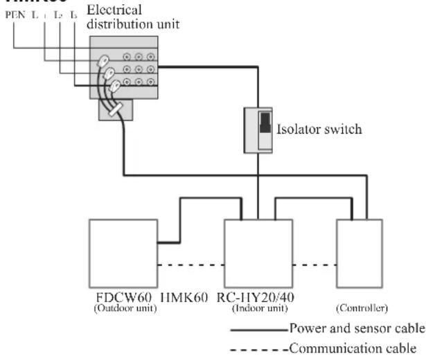
HMK60
flowchart
graph TD
    A["PN L1 L2 L3 Electrical distribution unit"] --> B["Isolator switch"]
    B --> C["FDCW60 (Outdoor unit)"]
    B --> D["IMK60 (Indoor unit)"]
    B --> E["RC-HY20/40 (Controller)"]
    C --> F["Power and sensor cable"]
    D --> G["Communication cable"]
    E --> H["Power and sensor cable"]
| Cable size | |
| Power – Indoor unit 5core, 2.5mm ^2 (power/communication cable) | |
| Indoor unit – Outdoor unit | 5core, 2.5mm ^2 (power/communication cable) |
| Indoor unit – Controller | 3core, 1.5mm ^2 (power cable)3core, 0.5mm ^2 , LiYY, EKKX or equivalent (communication cable) |
The cable size shown on the above table is reference value. Choose appropriate size according to local laws and regulations.
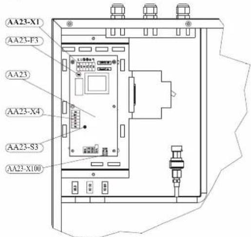
Electrical components
HSB60

Explanation
AA23 Communication board
AA23-F3 Fuse for external heating cable
AA23-S3 DIP switch, addressing of outdoor unit
AA23-X1 Terminal block, incoming supply, connection of KVR
AA23-X4 Terminal block, communication with indoor module / control module
AA23-X100 Terminal block, communication outdoor module FDCW
HMK60
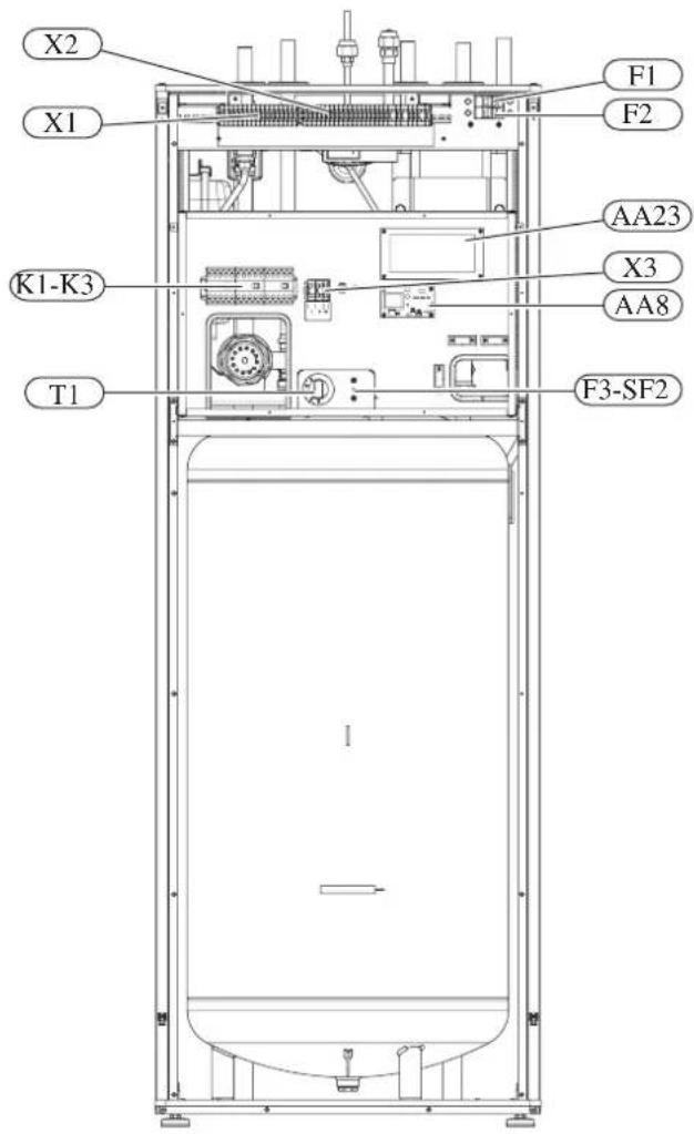
Explanation
X1 Terminal block, sensors
X2 Terminal block, power supply
X3 Terminal block
SF1 Controller switch
K1-K3 Submersible heater contact
T1 Thermostat, standby mode
F3 Temperature limiter
AA8 Titanium anode board
AA23 Communication board
F1 Circuit breaker, outdoor unit
F2 Circuit breaker, controller
UBI Cable grommet
UB2 Cable grommet
F3-SF2 Reset botton, temperature limiter
Temperature limiter
Temperature limiter (F3) cuts off the power supply of the electrical heating module if the temperature increases to the range of approximately 87 °C, and can be reset manually.
Resetting
Temperature limiter (F3) is accessible behind the front cover. Temperature limiter is reset by strong pressing of the button (F3-SF2) using a small screwdriver.
Press the button, max. 15 N (approx. 1.5 kg).

RC-HY20

Explanation
AA2 Base card
AA4 Display unit
AA4-XJ3 USB socket
AA4-XJ4 Service outlet (No function)
AA7 Extra relay circuit board
FA1 Miniature circuit-breaker
X1 Terminal block, incoming electrical supply
X2 Terminal block, control signal circulation pump, sensors AUX inputs and heat pump
SF1 Switch
PF3 Serial number plate
UB1 Cable grommet, incoming supply electricity, power for accessories
UB2 Cable grommet, signal
RC-HY40

Explanation
AA2 Base card
AA3 Input circuit board
AA4 Display unit
AA4-XJ3 USB socket
AA4-XJ4 Service outlet (No function)
AA5 Accessory card
AA7 Extra relay circuit board
FA1 Miniature circuit-breaker
K2 Emergency mode relay
X1 Terminal block, incoming electrical supply
X2 Terminal block, AUX4 - AUX6
SFI Switch
PF3 Serial number plate
UB1 Cable grommet, incoming supply electricity, power for accessories
UB2 Cable grommet, signal
Accessibility, electrical connection for controller
The cover of the control module is opened using a Torx 25 screwdriver. Assembly takes place in the reverse order.
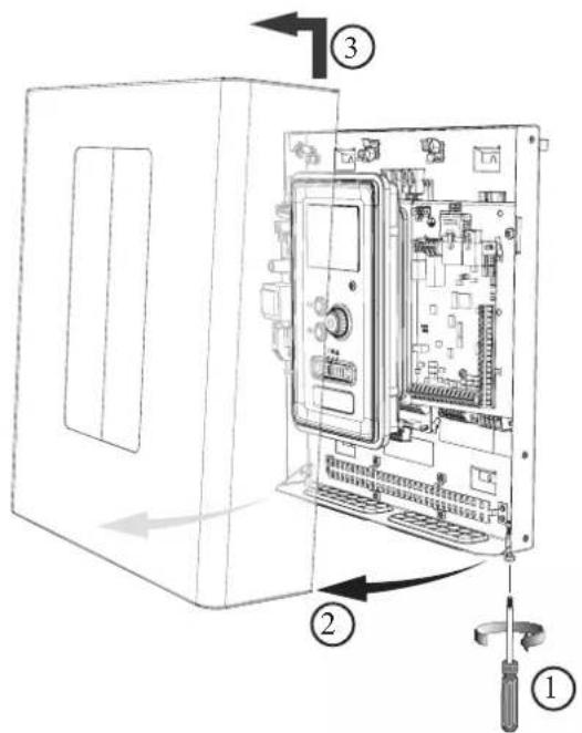
NOTE
The cover to access the base board is opened using a Torx 25 screwdriver

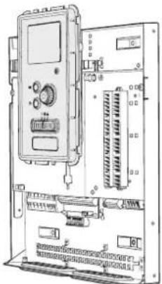
natural_image
Technical line drawing of an internal electronic device with labeled ports and connectors (no text or symbols present)The display may need to be moved for easier access when connecting electrics. This is easily done by following these steps.
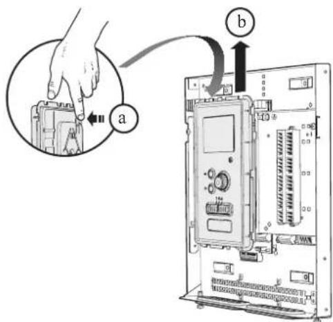
- Press in the catch on the upper rear side of the display unit towards you (a) and move the display unit upwards (b) so that the mountings unhook from the panel.
- Lift the display unit from its mountings.

- Align the two lower mountings on the reverse of the display unit with the two upper holes in the panel as illustrated.
natural_image
Technical line drawing of an electronic device chassis with control panel and drive unit (no text or labels)-
Secure the display on the panel.
-
When the electrical connection is ready the display must be reinstalled with three mounting points again, otherwise the front cover cannot be installed.
Cable lock
Use a suitable tool to release/lock cables in the terminal block.
HSB60, RC-HY20/40
Terminal block on the electrical card
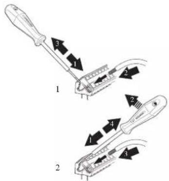
Terminal block
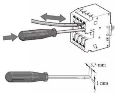
HMK60

Connection
NOTE
To prevent interference, unscreened communication and/or sensor cables to external connections must not be laid closer than 20 cm from high voltage cables.
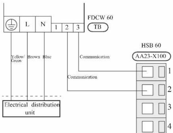
HSB60
Power supply
In case of HSB60, power supply is made to indoor unit, outdoor unit and controller separately. 230V 1AC 50Hz is applied.
For indoor unit, incoming supply is connected on AA23-X1 terminal.
For outdoor unit, incoming supply is connected on TB terminal. See figure on Connection between indoor and outdoor unit.
Connection between indoor and outdoor unit
The communication cable between indoor and outdoor unit is connected between terminal AA23-X100 in indoor unit and TB in outdoor unit. Screened 2 core cable is recommended.
Connection between indoor unit and controller
See Connection for RC-HY20/40
Cascade connection setting
In case of cascade connection system, it is necessary to allot unique address to each indoor unit. Set the dip switch S3-1, -2 and -3 according to the following table.
| Address S3:1 | S3:2 S3:3 | ||
| 1 OFF OFF OFF | |||
| 2 On OFF OFF | |||
| 3 OFF On OFF | |||
| 4 On On OFF | |||
| 5 OFF OFF On | |||
| 6 On OFF On | |||
| 7 OFF On On | |||
| 8 On On On | |||
Recommended fuse size for HSB60
The recommended fuse size shown in the following table is reference value. Choose appropriate size according to local laws and regulations.
| Fuse size | |
| Indoor unit (HSB60) 6A / 230V 1AC 50Hz | |
| Outdoor unit (FDCW60VNX-A) 20A / 230V 1AC 50Hz | |
| Controller (RC-HY20/40) 10A/ 230V 1AC 50Hz | |
| Electric heater (ELK9M)(reference) | 16 A/400V 3NAC 50Hz |
Recommended cable size for HSB60
The recommended cable size shown in the following table is reference value. Choose appropriate size according to local laws and regulations.
| Cable size | |
| Power – Indoor unit 3core, 1 | .5mm ^2 (power cable) |
| Power – Outdoor unit 3core, | 2.5mm ^2 (power cable) |
| Indoor unit – Outdoor unit | 2core, 1.5mm ^2 (communication cable) |
| Indoor unit – Controller | 3core, 0.5mm ^2 , LiYY, EKKX or equivalent (communication cable) |
HMK60
Circuit breaker
HMK60 is equipped with internal circuit breakers to protect the system and components. The circuit breaker F1 protects outdoor unit and F2 protects controller.
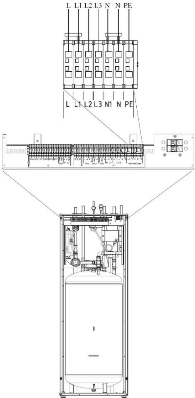
Power supply
In case of HMK60, power supply is made to indoor unit, and further connected to outdoor unit and controller. 400V 3NAC 50Hz is applied.
Connect power supply cable to the port for power supply on X2 terminal as shown below.
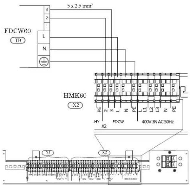
Connection between indoor and outdoor unit
For interconnection cable between indoor unit and outdoor unit, connect 2, 3, L, N and PE port for outdoor unit on X2 terminal on HMK60 to 2, 3, L, N, and ⏱ port on FDCW60 respectively according to the below figure.
Connection between indoor unit and controller
See Connection for RC-HY20/40.
Recommended fuse size for HMK60
The recommended fuse size shown in the following table is reference value. Choose appropriate size according to local laws and regulations.
| Fuse size | |
| Indoor unit (HMK60) 25A / 400V | 3NAC 50Hz |
Recommended cable size for HMK60
The recommended fuse size shown in the following table is reference value. Choose appropriate size according to local laws and regulations.
| Cable size | |
| Power – Indoor unit 5core, 2.5mm ^2 (power/communication cable) | |
| Indoor unit – Outdoor unit 5core, 2.5mm ^2 (power/communication cable) | |
| Indoor unit – Controller 3core, 1.5mm ^2 (power cable)3core, 0.5mm ^2 , LiYY, EKKX or equivalent (communication cable) | |
RC-HY20/40
Cable connection is different according to the system structure. Refer to the connection method according to the indoor unit.
Power supply
HSB60
Connect power cable on X1 terminal as shown below.
RC-HY 20/40 must be installed via an isolator switch with a minimum breaking gap of 3 mm. Minimum cable area must be sized according to the fuse rating used.
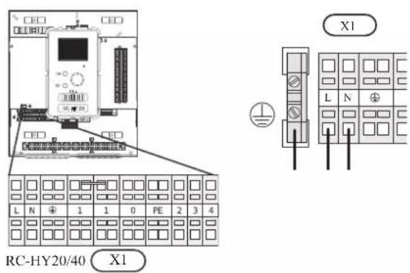
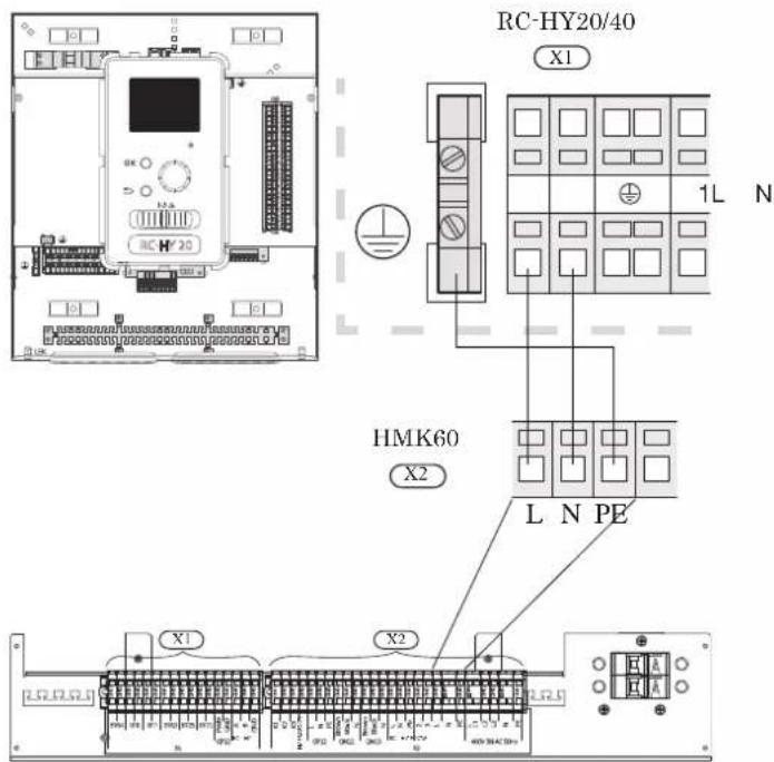
HMK60
Power is supplied through indoor unit. Connect the port L, N and ⏻ on X1 terminal on RC-HY20/40 to the port L, N and PE for controller on X2 terminal on HMK60 respectively as shown below.
Connection between controller and indoor unit HSB60
Signal cable is connected between controller and indoor unit with screened 3 core cable for HSB60. Choose correct terminal according to the type of controller as shown below.
Connect the port 19(A), 20(B) and 21(GND) on X2 terminal on RC-HY20 to the port 1, 2 and 3 on X4 terminal on AA23 board on HSB60 respectively.
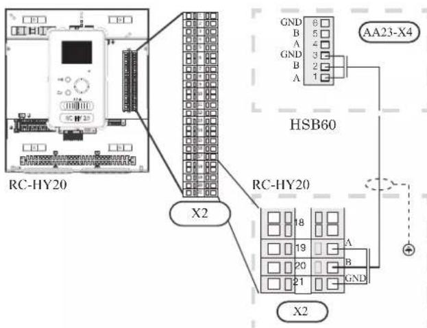
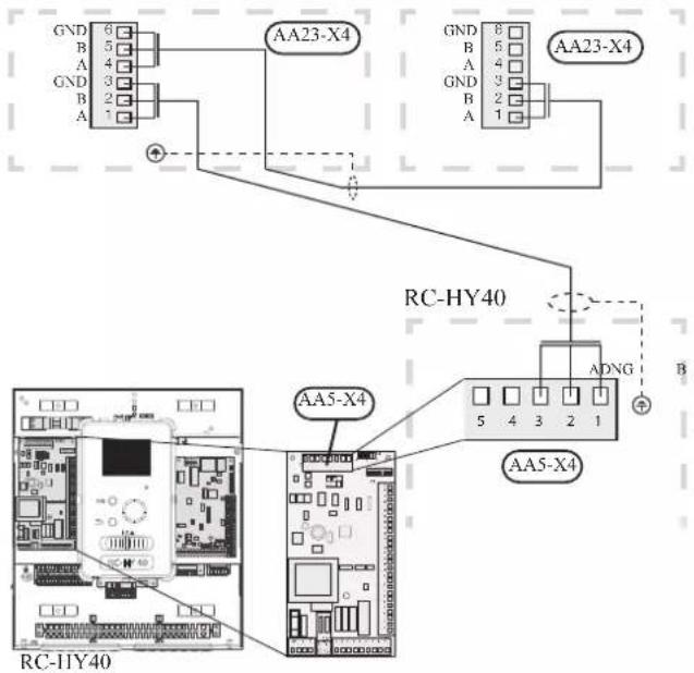
Connect the port 1(A), 2(B) and 3(GND) on X4 terminal on AA5 board on RC-HY40 to the port 1, 2 and 3 on X4 terminal on AA23 board on HSB60 respectively.
In case several systems are connected to one controller, connect the port 4, 5 and 6 on X4 terminal on AA23 board on HSB60 close to the controller to the port 1, 2 and 3 on X4 terminal on AA23 board on another HSB60.
HSB60 HSB60
HMK60
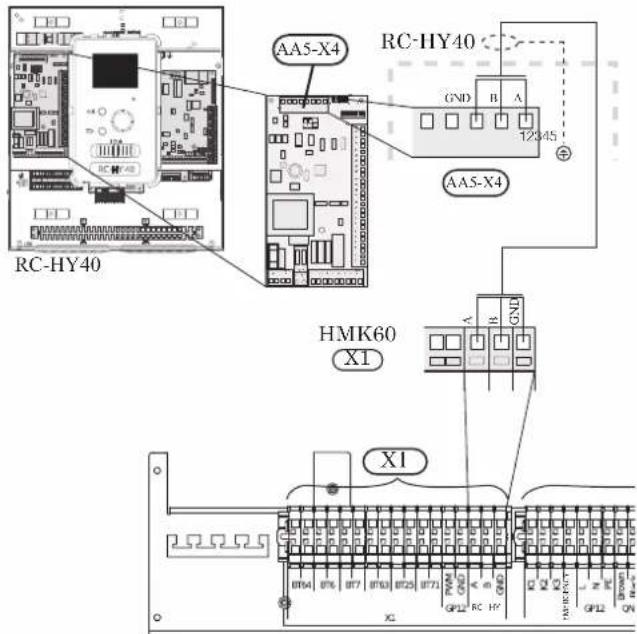
Communication cable and pump cable are connected between controller and indoor unit. with screened 3 core cable for HMK60. Choose correct terminal according to the type of controller as shown below.
Communication cable
Connect the port 19(A), 20(B) and 21(GND) on X2 terminal on RC-HY20 to the port A, B and GND for EB101 on X1 terminal on HMK60 respectively.
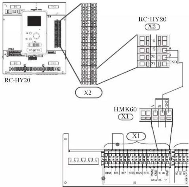
Connect the port 1(A), 2(B) and 3(GND) on X4 terminal on AA5 board on RC-HY40 to the port A, B and GND for EB101 on X1 on HMK60 respectively.
Connection between controller and circulation pump (GP12)
HSB60
For HSB60, circulation pump (GP12) is installed outside of indoor unit. Choose correct terminal according to the type of controller.
Connect the port 5, 6 and 7 on X4 terminal on AA2 board on RC-HY20/40 to the port PE, N and L on circulation pump respectively. Control signal cable is connected between the port 1 and 2 on X2 terminal on RC-HY20 and PWM and GND on circulation pump respectively as shown below.
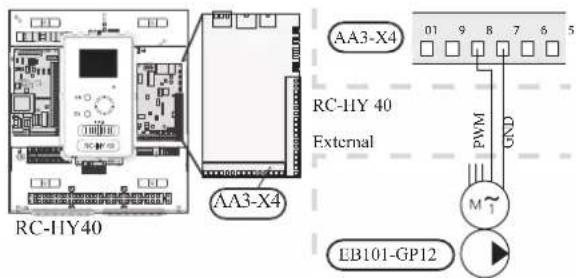
Connect the port 5, 6 and 7 on X4 terminal on AA2 board on RC-HY40 to the port PE, N and L on circulation pump (EB101-GP12) respectively. Control signal cable is connected between the port 7 and 8 on X4 terminal on AA3 board on RC-HY40 and GND and PWM on circulation pump respectively as shown below.
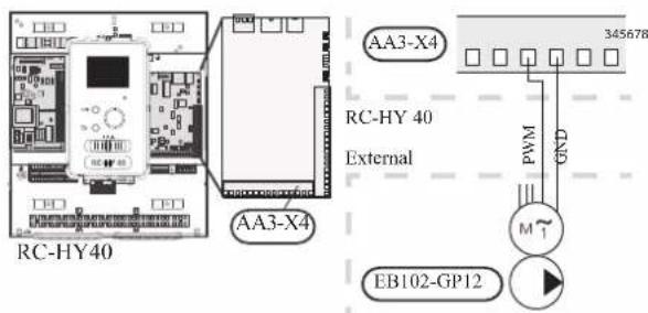
RC-HY40 can connect and control up to two pumps. Connect the port 12, 13 and 15 on X4 terminal on AA2 board on RC-HY40 to the port PE, N and L on second circulation pump (EB102-GP12) respectively. Control cable is connected between the port 5 and 6 on X4 terminal on AA3 board on RC-HY40 and GND and PWM on circulation pump respectively as shown below.

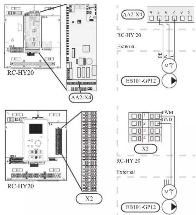
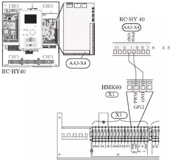
HMK60
HMK60 is equipped with circulation pump (GP12). Choose correct terminal according to the type of controller.
Connect the port 5, 6 and 7 on X4 terminal on AA2 board to the port L, N and PE for GP12 on X2 terminal on HMK60 respectively.
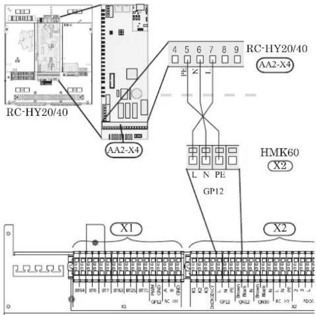
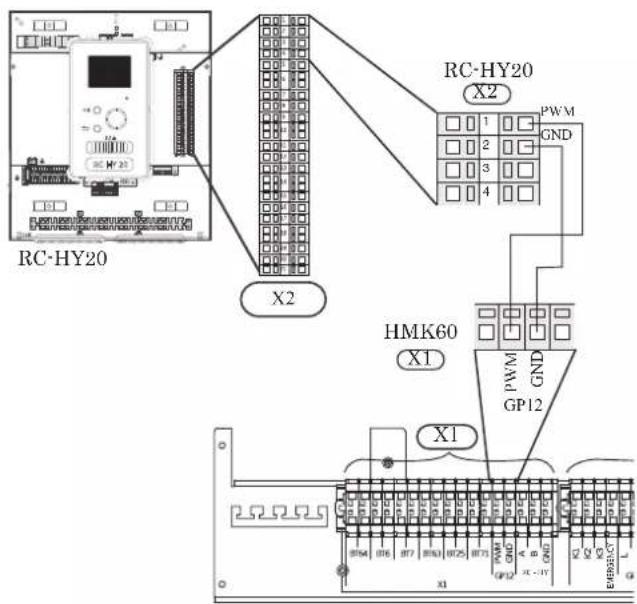
Also, connect the port 1 and 2 on X2 terminal to the port PWM and GND for GP12 on X1 terminal on HMK60 respectively as shown below.
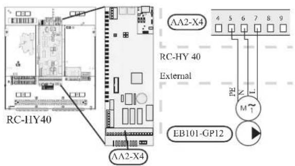
Connect the port 5, 6 and 7 on X4 terminal on AA2 board to the port L, N and PE for GP12 on X2 terminal on HMK60 respectively (same as with RC-HY20).
Also, connect the port 7 and 8 on X4 terminal on AA3 board to the port PWM and GND for GP12 on X1 terminal on HMK60 respectively as shown below.
Connection between controller and 3-way valve (QN10/QN12)
3-way valve is used for switching heating / hot water production (QN10), or switching heating / cooling (QN12). Install appropriate valves according to the system structure on site.
HSB60
HSB60 is not equipped with 3-way valve. Install the valves on right position according to the diagram and connect wires on appropriate port according to the type of controller.
• 3-way valve for Heating / Hot water (QN10)
Connect the N, Control and L wire on 3-way valve to the port 2, 3 and 4 on X4 terminal on AA2 board on RC-HY20/40 respectively as shown below.
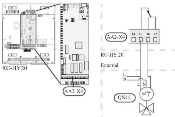
• 3-way valve for Heating / Cooling (QN12)
QN12 can be controlled with potential free variable relay. Connect L and Control wire on 3-way valve to the port 15 and 16 on X4 terminal on AA2 board on RC-HY20 respectively. Also, connect L and N wire to power supply as shown below.
Additional setting is necessary in menu 5.4. See Menu system for details.
CAUTION
The relay outputs can have a max load of 2 A at resistive load (230V AC).
• 3way valve for Heating / Hot water (QN10)
Refer to 3-way valve connection for HSB60 with RC-HY20.
• 3 way valve for Heating / Cooling (QN12)
QN12 can be controlled with potential free variable relay. Connect L and Control wire on 3-way valve to the port C and NO on X7 terminal on AA3 board on RC-HY40 respectively. Also, connect L and N wire to power supply as shown below.
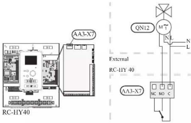
CAUTION
The relay outputs may be subjected to a max load of 2A at resistive load (230V AC).
HMK60
HMK60 is equipped with both QN10 (for switching heating / hot water) and QN12 (for switching heating / cooling). Connect wires on appropriate port according to the type of controller.
• 3way valve for Heating / Hot water (QN10)
Connect the port 2, 3 and 4 on X4 terminal on AA2 board on RC-HY20/40 to the port N, Black and Brown for QN10 on X2 terminal on HMK60 respectively as shown below.
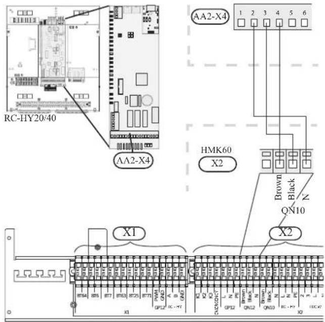
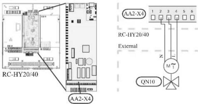
• 3 way valve for Heating / Cooling (QN12)
Connect the port 15 and 16 on X3 terminal on AA2 board on RC-HY20 to the port Brown and Black for QN12 on X2 terminal on HMK60 respectively. Also, connect to the port 0 on X1 terminal on RC-HY20 to N port for QN12 on X2 terminal on HMK60. In addition, connect the port 1 on X1 terminal to the port 15 on X4 terminal on AA2 board on RC-HY20.
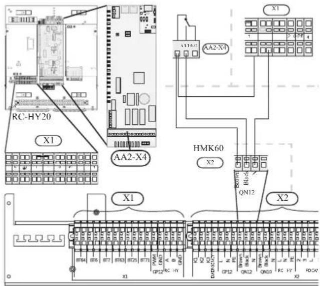
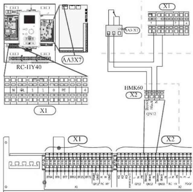
• 3way valve for Heating / Hot water (QN10)
Refer to 3-way valve connection for HMK60 with RC-HY20.
• 3 way valve for Heating / Cooling (QN12)
Connect the port C and NO on X7 terminal on AA3 board on RC-HY40 to the port Brown and Black for QN12 on X2 terminal on HMK60 respectively. Also, connect the port 0 on X1 terminal on RC-HY40 to N port for QN12 on X2 terminal on HMK60. In addition, connect the port 1 on X1 terminal to the port C on X7 terminal on AA3 board on RC-HY40.
Connection between controller and sensors
Sensor connection is different according to the combination of indoor unit and controller. Refer to the appropriate combination mentioned below.
Use two-core cable with a minimum 0.5mm2 cross section.
Regarding other sensors not mentioned in this chapter, refer to page 49, Optional connections.
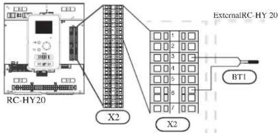
- Ambient air temperature sensor BT1
Install ambient air temperature sensor (BT1) in the shade on a wall facing north or north-west, so it is unaffected by the morning sun.
Connect the sensor to the port 3 and 6 on X2 terminal.
If a conduit is used it must be sealed to prevent condensation in the sensor capsule.
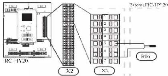
• Hot water charging sensor BT6 (tank bottom)
The temperature sensor, hot water charging (BT6) is placed in the submerged tube on the water heater.
Connect the sensor to the port 5 and 6 on X2 terminal.
Hot water charging is activated in menu 5.2 or in the start guide.
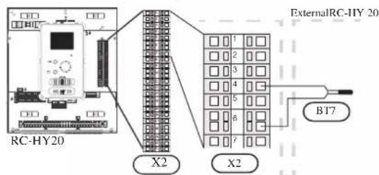
• Hot water sensor BT7 (tank top)
A temperature sensor for hot water top (BT7) can be connected to RC-HY20 to show the water temperature at the top of the tank (if it is possible to install a sensor at the top of the tank).
Connect the sensor to the port 4 and 6 on X2 terminal.
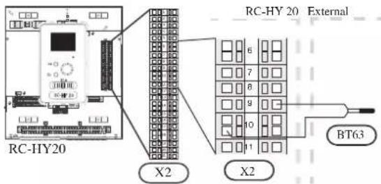
• Temperature sensor BT63, outlet at additional heater
This sensor is used in case electric heater is placed before 3-way valve (QN10) for switching heating/hot water (see page 26 for diagram).
Connect temperature sensor, external supply after electric heater (BT63) to the port 9 and 10 on terminal X2.
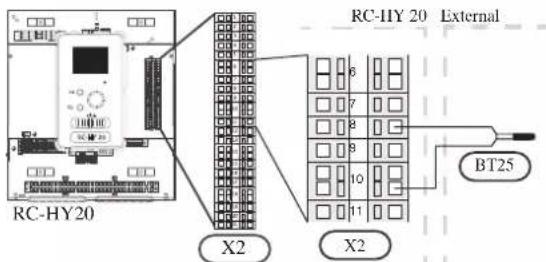
• Temperature sensor BT25, outlet for heating
This sensor is used in case electric heater is placed after 3 way valve (QN10) for switching heating/ hot water (see page 27 for diagram).
Connect temperature sensor, external supply (BT25) to the port 8 and 10 on X2 terminal.
• Temperature sensor BT71, return line for heating
This sensor is used in case electric heater is placed after 3 way valve (QN10) for switching heating/ hot water (see page 27 for diagram).
For connection, see page 50, AUX inputs.
• Temperature sensor BT64, outlet for cooling
This sensor is used in case cooling application is required.
For connection, see page 51, AUX inputs.
• Ambient air temperature sensor BT1
Refer to the connection RC-HY20 with HSB60.
• Hot water charging sensor BT6 (tank bottom)
The temperature sensor, hot water charging (BT6) is placed at the bottom part of the water heater. Connect the port 5 and 6 on X2 terminal on RC-HY20 to the port BT6 on X1 terminal on HMK60.
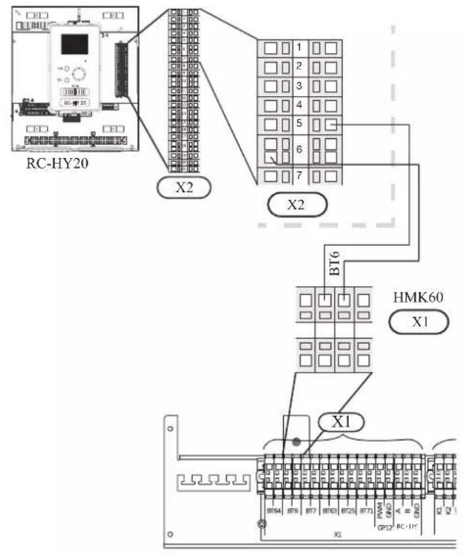
• Hot water sensor BT7 (tank top)
The temperature sensor, hot water top (BT7) is placed at the top of the water heater. Connect the port 4 and 6 on X2 terminal on RC-HY20 to the port BT7 on X1 terminal on HMK60.
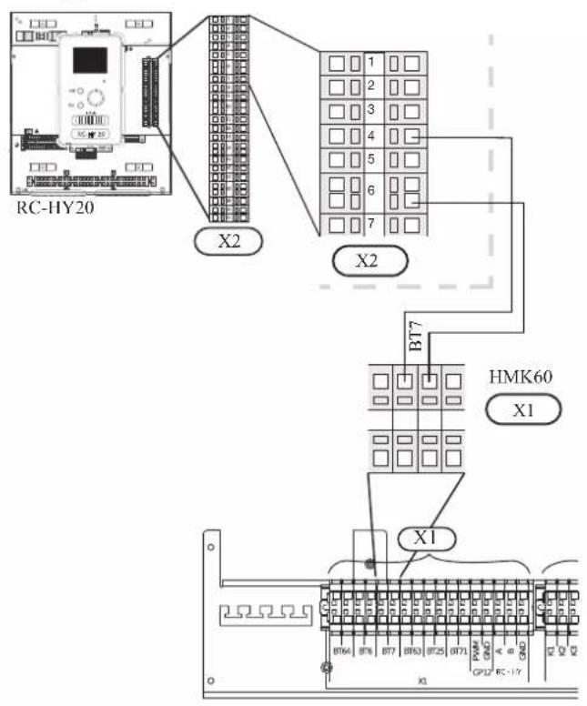
• Temperature sensor BT63, outlet at additional heater
The temperature sensor BT63 is placed on the outlet at additional heater. Connect the port 9 and 10 on X2 terminal on RC-HY20 to the port BT63 on X1 terminal on HMK60.
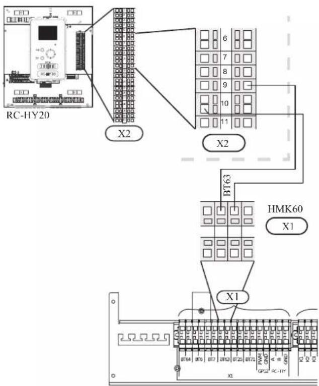
• Temperature sensor BT25, outlet for heating
The temperature sensor BT 25 is placed on the supply line for heating. Connect the port 8 and 10 on X2 terminal on RC-HY20 to the port BT25 on X1 terminal on HMK60.
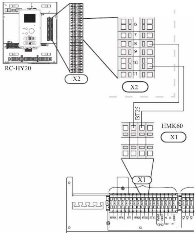
• Temperature sensor BT71, return pipe
The temperature sensor BT71 is placed on the return pipe line for water heater. For connection, see page 50, AUX inputs.
• Temperature sensor BT64, outlet for cooling
The temperature sensor BT64 is placed on the supply line for cooling. For connection, see page 51, AUX inputs.
- Ambient air temperature sensor BT1
Install ambient air temperature sensor (BT1) in the shade on a wall facing north or north-west, so it is unaffected by the morning sun for example.
Connect the sensor to the port 1 and 2 on X6 terminal on AA3 board.
If a conduit is used it must be sealed to prevent condensation in the sensor capsule.
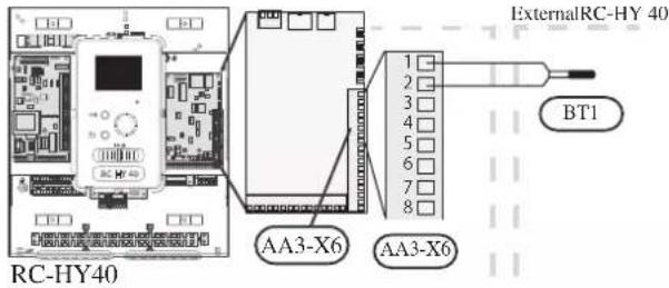
• Hot water charging sensor BT6 (tank bottom)
The temperature sensor, hot water charging (BT6) is placed in the submerged tube on the water heater.
Connect the sensor to the port 7 and 8 on X6 terminal on AA3 board.
Hot water charging is activated in menu 5.2 or in the start guide.
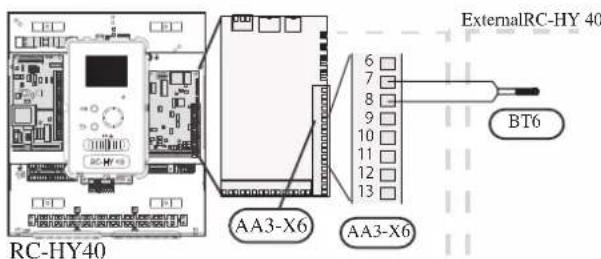
• Hot water sensor BT7 (tank top)
A temperature sensor for hot water top (BT7) can be connected to RC-HY40 to show the water temperature at the top of the tank (if it is possible to install a sensor at the top of the tank).
Connect the sensor to the port 15 and 16 on X6 terminal on AA3 board.
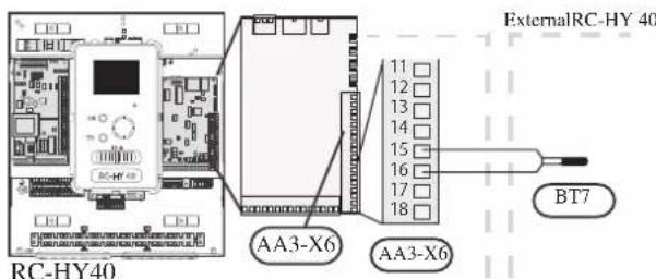
• Temperature sensor BT63, outlet at additional heater
This sensor is used in case electric heater is placed before 3 way valve (QN10) for switching heating/ hotwater (see page 26 for diagram).
For connection, see page54, AUX inputs.
• Temperature sensor BT25, outlet for heating
This sensor is used in case electric heater is placed after 3 way valve (QN10) for switching heating/ hot water (see page 27 for diagram).
Connect temperature sensor, external supply line (BT25) to the port 5 and 6 on X6 terminal on AA3 board.
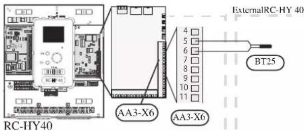
• Temperature sensor BT71, return line for heating
This sensor is used in case electric heater is placed after 3 way valve (QN10) for switching heating/ hot water (see page 27 for diagram).
Connect temperature sensor, external return line (BT71) to the port 17 and 18 on X6 terminal on AA3 board.
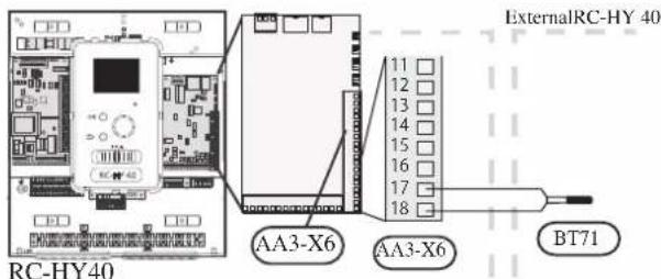
• Temperature sensor BT64, outlet for cooling
This sensor is used in case cooling application is required. For connection, see page 54, AUX inputs.
• Ambient air temperature sensor BT1
Refer to the connection RC-HY40 with HSB60.
• Hot water charging sensor BT6 (tank bottom)
The temperature sensor, hot water charging (BT6) is placed at the bottom part of the water heater. Connect the port 7 and 8 on X6 terminal on AA3 board on RC-HY40 to the port BT6 on X1 terminal on HMK60.
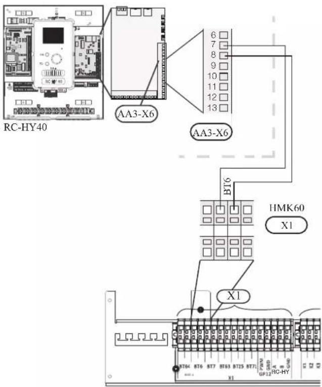
• Hot water sensor BT7 (tank top)
The temperature sensor, hot water top (BT7) is placed at the top of the water heater. Connect the port 15 and 16 on X6 terminal on AA3 board on RC-HY40 to the port BT7 on X1 terminal on HMK60.
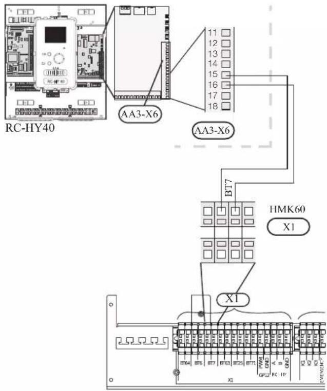
• Temperature sensor BT63, outlet at additional heater
The temperature sensor BT63 is placed on the outlet at additional heater. For connection, see page 54, AUX inputs.
• Temperature sensor BT25, outlet for heating
The temperature sensor BT 25 is placed on the supply line for heating. Connect the port 5 and 6 on X6 terminal on RC-HY40 to the port BT25 on X1 terminal on HMK60.
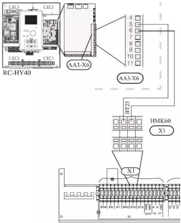
• Temperature sensor BT71, return pipe
The temperature sensor BT71 is placed on the return pipe line for water heater. Connect the port 17 and 18 on X6 terminal on AA3 board on RC-HY40 to the port BT71 on X1 terminal on HMK60.
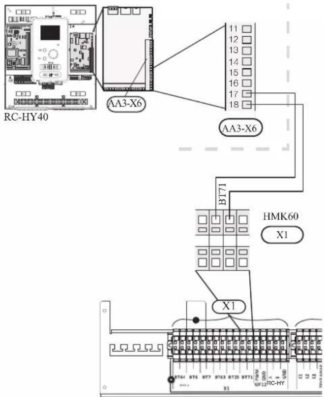
• Temperature sensor BT64, outlet for cooling
The temperature sensor BT64 is placed on the supply line for cooling. For connection, see page 54, AUX inputs.
Optional connections
RC-HY20
• Room sensor BT50
Room sensor can be connected to controller.
The room temperature sensor has up to three functions:
- Show current room temperature in the control module display.
- Option of changing the room temperature in °C.
- Makes it possible to change/stabilise the room temperature.
Install the sensor in a neutral position where the set temperature is required. A suitable location is on a free inner wall in a hall approx. 1.5 m above the floor.
Do not install the sensor where correct room temperature cannot be detected such as in a recess, between shelves, behind a curtain, above or close to a heat source, in a draft from an external door or in direct sunlight.
Closed radiator thermostats can also cause problems.
The control module can operate without the sensor, but if user wants to read off the accommodation's indoor temperature in controller display, the sensor must be installed.
Connect the room sensor to the port 7 and 10 on X2 terminal.
If the sensor is to be used to change the room temperature in ^ C and/or to change/stabilise the room temperature, the sensor must be activated in menu 1.9.4.
If the room sensor is used in a room with underfloor heating, it should only have an indicative function, not control of the room temperature.
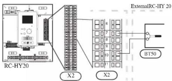
CAUTION
Changes of temperature in accommodation take time. For example, short time periods in combination with underfloor heating will not give a noticeable difference in room temperature.
Use two-core cable with a minimum 0.5mm^2 cross section.
- Step controlled additional heat
NOTE
Mark up any junction boxes with warnings for external voltage.
External step controlled additional heat can be controlled by up to three potential-free relays in the control module (3 step linear or 7 step binary). Alternatively two relays (2 step linear or 3 step binary) can be used for step controlled additional heat, which means that the third relay can be used to control the immersion heater in the water heater/accumulator tank.
Step in occurs with at least 1 minute intervals and step outs with at least 3 seconds intervals.
Step 1 is connected to terminal block X2:2 on the additional relay board (AA7).
Step 2 is connected to terminal block X2:4 on the additional relay board (AA7).
Step 3 or immersion heater in the water heater/accumulator tank is connected to terminal block X2:6 on the additional relay board (AA7).
The settings for step controlled additional heat are made in menu 4.9.3 and menu 5.1.12.
All additional heat can be blocked by connecting a potential-free switch function to the software controlled input on terminal block X2 which is selected in menu 5.4.
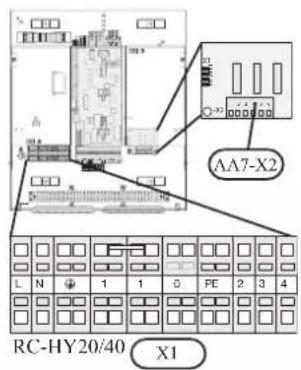
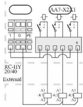
If the relays are to be used for control voltage, bridge the supply from terminal block X1:1 to X2:1, X2:3 and X2:5 on additional relay board (AA7). Connect the neutral from the external additional heat to terminal block X1:0.
Use a cable with appropriate cross section.
For connection, see the installation manual for additional heater.
Connect the port 2, 4, 6 on X2 terminal on AA7 board on RC-HY20/40 to the port K1, K2, K3 on X2 terminal on HMK60 respectively.

• Relay output for emergency mode
NOTE
Mark up any junction boxes with warnings for external voltage.
When the switch (SF1) is in " " mode (emergency mode) the circulation pump is activated (EB101-GP12).
CAUTION
No hot water is produced when emergency mode is activated.
The emergency mode relay can be used to activate external additional heat. Between the port 2 and 4 is closed during emergency mode. An external thermostat must be connected to the control circuit (port 4) to control the temperature. Ensure that the heating medium circulates through the external additional heating.
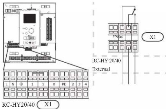
If the relay is to be used for control voltage, bridge the supply from terminal block X1:1 to X1:2 and connect neutral and control voltage from the external additional heat to X1:0 (N) and X1:4 (L).
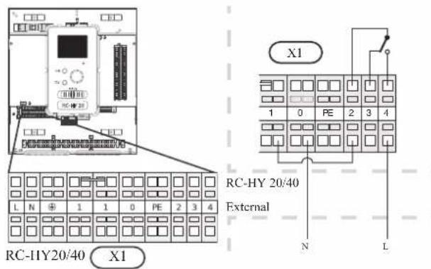
Connect the port 4 on X1 terminal on RC-HY20/40 to EMERGENCY on X2 terminal on HMK60, as well as the port 0 on X1 terminal on RC-HY20/40 to Neutral on HMK60.
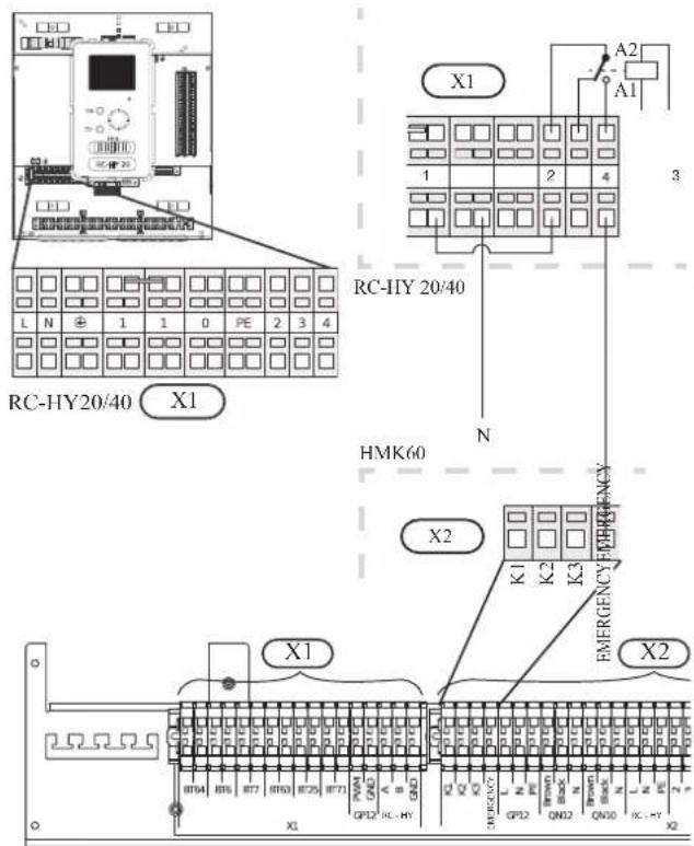
Set the supply temperature with the thermostat T1 in case of emergency mode. The setting range is 6-67°C. For floor heating, the setting must be min.20°C to max. 35-45°C in order to preserve heat comfort in the room and ensure effective system operation. When the temperature is set at 35°C or higher, be careful not to cause low temperature burn.
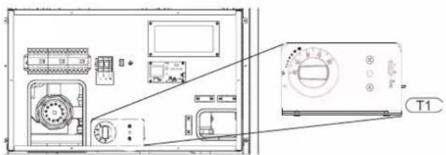
• External circulation pump
Connect the external circulation pump (GP10) to terminal block X4:9 (PE), X4:10 (N) and X4:11 (230 V) on the base board (AA2) as illustrated.
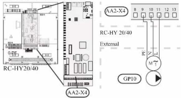
- AUX inputs
Other external inputs are available on the port 11 through 18 on X2 terminal on RC-HY20.
AUX1, 2, 3, 4, 5, and 6 correspond to the port 11, 12, 13, 15, 16 and 17 respectively. Port 14 and 18 are GND and are common to the all auxiliary circuit. Connect a sensor or switch between AUX and GND with a two-core cable with a minimum cross section of 0.5mm ^2 .

Select the appropriate function in menu 5.4.
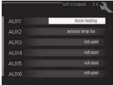
■ Temperature sensor, cooling/heating (BT74)
Additional room sensor (BT74) is applied in case user wants to determine the operation mode (cooling/heating) with a temperature in a particular room.
This option can be chosen only in case cooling function is available.
■ Temperature sensor, external return line (BT71)
Temperature sensor BT71 is applied in case additional heater is placed after 3-way valve (see page 27 and 28 for diagram).
■ Temperature sensor, flow line cooling (BT64)
Temperature sensor BT64 is required in case 4-pipe system is used for cooling operation. (see page 26-28 for diagram) This option can be chosen only in case cooling function is activated.
■ Contact for external tariff blocking
In cases where external tariff blocking is required it must be connected to terminal block X2.
Tariff blocking means that the additional heat, the compressor, heating and cooling are disconnected by connecting a potential free switch function to the input selected in menu 5.4.
A closed contact results in the electrical output being disconnected.
■ Switch for "SG ready"
NOTE
This function can only be used in mains networks that support the "SG Ready"-standard. "SG Ready" requires two AUX inputs.
This function can only be used in power supply networks that support the “SG Ready” standard. “SG Ready” requires two AUX inputs.
“SG Ready” is a smart tariff management scheme in which electricity supplier can affect indoor and hot water temperature or simply prohibits additional heat and/or the compressor operation in heat pump at certain period of the day. You can choose which operation mode is affected by this function in menu 4.1.5 after the function is activated.
Choose two external input circuits and connect potential-free switches, and set "SG Ready A" and "SG Ready B" in menu 5.4. The system works differently according to the combination of the circuit open/closed.
- Blocking (A: Closed, B: Open)
“SG Ready” is active. Compressor operation and additional heat is prohibited.
• Normal mode (A: Open, B: Open)
"SG Ready" is not active. No effect on the system. - Low price mode (A: Open, B: Closed)
"SG Ready" is active. The system operates to provide higher capacity than normal mode by using lower tariff electricity. You can select the operation mode (heating/hot water/cooling) affected by this function in menu 4.1.5.
• Overcapacity mode (A: Closed, B: Closed)
“SG Ready” is active. The system supplies higher capacity than Low price mode since the electricity price is supposed to be very low in this mode. You can select the operation mode (heating/hot water/cooling) affected by this function in menu 4.1.5.
■Contact for activation of “temporary lux”
Temporary hot water production function “temporary lux” is activated with this signal. Connect the terminals with a potential-free switch and choose the function in menu 5.4.
"Temporary lux" is activated only when the switch is closed.
■Contact for activation of “external adjustment”
Target temperature offset for supply temperature or room temperature can be done with this signal.
When a room sensor is connected and activated, the target room temperature is offset in ^ C if the switch is closed. When a room sensor is not connected, target supply water temperature (heat curve) is offset instead. The degree of off set can be set in menu 5.4.
■Switch for external alarm
Alarms from external devices can be connected to the control and appear as an info alarm. Potential-free signal of NO or NC type can be connected.
■Switch for external blocking
This function is used in case certain operation mode needs to be prohibited. The operation at selected operation mode is prohibited when the switch is closed. Following functions can be managed.
• Additional heat
- compressor operation
- heating mode
- cooling mode
- hot water mode
- AUX outputs
External output is available on the port 15 to 17 on X4 terminal on AA2 board on RC-HY20. The relay output can have a max load of 2A at resistive load.
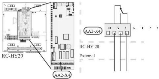
Following functions are available. Select the function in menu 5.4.
• Indication of buzzer alarm
When an alarm occurs, the circuit becomes closed between the port 15 and 16. During normal operation, the port 15 and 17 is closed.
- Cooling mode indication / Active cooling mode (4-pipe cooling)
When the system turns into cooling mode, the circuit becomes closed between the port 15 and 16. By using this signal, it is possible to switch 3-way valve for 4-pipe cooling or to assemble a display circuit indicating cooling mode. For details of connecting the 3-way valve, refer to page 40 to 41
• External pump control (GP10)
External pump (GP10) is used in case additional heater is placed after 3-way valve that switches heating/hot water (refer to page 27 for diagram).
Connect the circulation pump as shown below using the port 15 and 16 on X4 terminal.
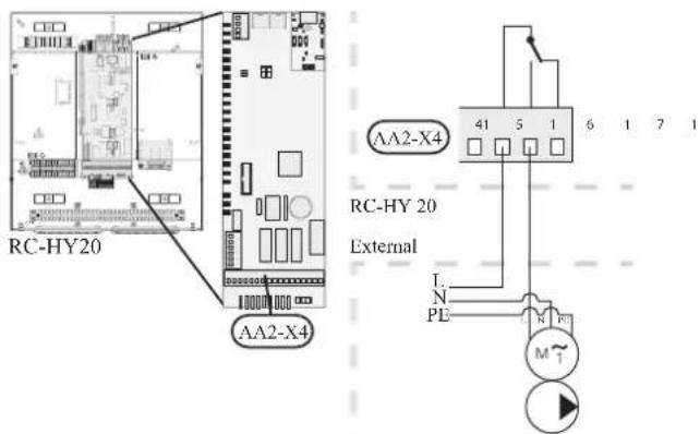
• Hot water circulation pump control (GP11)
In case the distance between hot water tap and hot water storage tank is far, the hot water supply line temperature is likely to drop and it may take time to supply hot water from the tap. In that case, hot water circulation pump (GP11) is applied to maintain hot water supply line temperature warm (refer to page 22 for diagram).
For details of connecting the pump, refer to External pump control (GP10).
NOTE
Mark up any junction boxes with warnings for external voltage.
- myUpway™
Connect the network connected cable (straight, Cat.5e UTP) with RJ45-contact (male) to contact AA4-X9 on the display unit (as illustrated). Use the cable grommet (UB2) in the control module for cable routing.
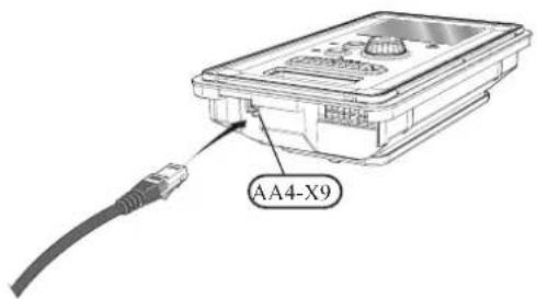
RC-HY40
- Load monitor
In case many power electrical appliances are connected in the property and the electric heater is energised at the same time, there is a risk of tripping the main fuse of the property.
The control module has an integrated load monitor that controls the power steps of the electric heater by disconnecting step by step in the event of overload in a phase. It will be reconnected if other current consumption is reduced.
Connecting current sensors
A current sensor (BE1 - BE3) should be installed on each incoming phase conductor in to the electrical distribution unit to measure the current. This is best done in the electrical distribution unit.
Connect the current sensors to a multi-core cable in an enclosure next to the electrical distribution unit. Use a multi-core cable of at least 0.5 mm^2 from the enclosure to the heat pump.
Connect the cable to terminal block X4:1 to 4.
X4:1 is the common terminal block for the three current sensors.
Set the size of the property's main fuse in menu 5.1.12.
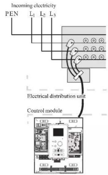

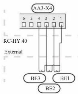
• Room sensor BT50
Refer to Room sensor BT50 for RC-HY20 for function and installation place.
Connect the room sensor to terminal block X6:3 and X6:4 on the input board (AA3).
If the sensor is to be used to change the room temperature in ^ C and/or to change/stabilise the room temperature, the sensor must be activated in menu 1.9.4.
If the room sensor is used in a room with underfloor heating, it should only have an indicative function, not control of the room temperature.
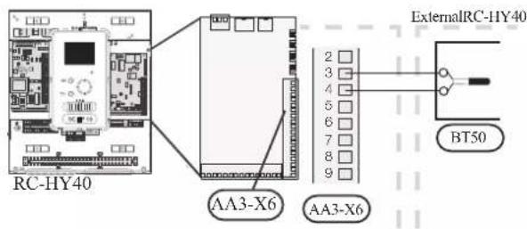
CAUTION
Changes of temperature in accommodation take time. For example, short time periods in combination with underfloor heating will not give a noticeable difference in room temperature.
- Step controlled additional heat
Refer to the explanation for RC-HY20. - Relay output for emergency mode
Refer to the explanation for RC-HY20.
• External circulation pump
Refer to the explanation for RC-HY20.
- AUX inputs
Up to 6 other external inputs are available on RC-HY40.
AUX1 through 3 correspond to the port 9/10, 11/12, 13/14 respectively on X6 terminal on AA3 board. AUX4 through 6 correspond to the port 1, 2 and 3 on X2 terminal on RC-HY40. Port 4 on X2 terminal is GND and is common to AUX4 through 6. Connect a sensor or switch between AUX and GND with a two-core cable with a minimum cross section of 0.5mm ^2 .

Select the appropriate function in menu 5.4.
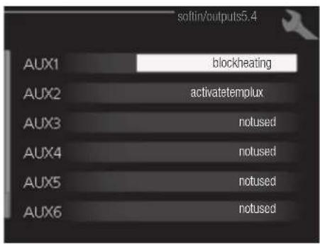
■ Temperature sensor, external supply at additional heat before reversing valve (BT63)
Temperature sensor BT63 is applied in case additional heater is placed before 3-way valve (see page 26 for diagram)
The following functions are available. For details, see AUX inputs for RC-HY20.
■ Temperature sensor, cooling/heating (BT74)
■ Temperature sensor, external return line (BT71)
■ Temperature sensor, flow line cooling (BT64)
■ Contact for external tariff blocking
■ Switch for "SG ready"
■Contact for activation of "temporary lux"
■Contact for activation of "external adjustment"
■Switch for external alarm
■Switch for external blocking
- AUX outputs
External output is available on the port NC, NO and C on X7 terminal on AA3 board on RC-HY40. The relay output can have a max load of 2A at resistive load.
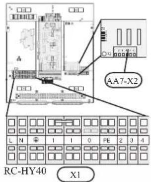
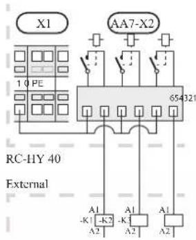
Following functions are available. Select the function in menu 5.4.
- Indication of buzzer alarm
When an alarm occurs, the circuit becomes closed between the port NO and C. During normal operation, the port NC and C is closed. - Cooling mode indication / Active cooling mode (4-pipe cooling)
When the system turns into cooling mode, the circuit becomes closed between the port NO and C. By using this signal, it is possible to switch 3-way valve for 4-pipe cooling or to assemble a display circuit indicating cooling mode. For details of connecting the 3-way valve, refer to page 40 and 41
• External pump control (GP10)
External pump (GP10) is used in case additional heater is placed after 3-way valve that switches heating/hot water (refer to page 27 and 28 for diagram).
Connect the circulation pump using the port NO and C on X7 terminal on AA3 board as shown below.

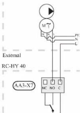
• Hot water circulation pump control (GP11)
In case the distance between hot water tap and hot water storage tank is far, the hot water supply line temperature is likely to drop and it may take time to supply hot water from the tap. In that case, hot water circulation pump (GP11) is applied to maintain hot water supply line temperature warm (refer to page 22 for diagram).
For details of connecting the pump, refer to External pump control (GP10).
NOTE
Mark up any junction boxes with warnings for external voltage.
- myUpway™
Connect the network connected cable (straight, Cat.5e UTP) with RJ45-contact (male) to contact AA4-X9 on the display unit (as illustrated). Use the cable grommet (UB2) in the control module for cable routing.

Commissioning and adjusting Preparations
Before starting commissioning, check the followings;
- The signal cable is connected between indoor unit and outdoor unit as well as indoor unit and controller according to the instruction.
- The power cable is connected to indoor unit, outdoor unit and controller according to the instruction.
- Operation switch in controller is in the position ⏻.
- The service valves on outdoor unit (QM35 and QM36) are open.
- Drain valve is closed before filling water in the system.
• Temperature limiter and electrical switch are not tripped. - The system is filled with water and well vented.
• There are no leaks on the water pipe.
Filling and venting
Hot water tank
- Open the hot water tap as well as venting valve if applicable, and then open the cold water cut-off valve at the inlet.
- Fill the storage tank until obtaining uniform water outflow at the hot water tap, and then close the hot water tap and venting valve.
- Fill the water heater coil in the tank. See Climate system for details.
After the installation and levelling the tank, follow the procedure below (for the connector pipe symbols, refer to page 18):
- Remove protecting plugs from the connector pipes
- Connect the hot water intake line (N).
- Connect the cold water supply line together with the required safety valves (G).
- If the system has the hot water circulati on system, connect it to the connector pipe (L). Otherwise, plug the pipe.
- Connect the supply (J) and return (H) of the heating medium to the coil.
CAUTION
If there is an electric heating module installed in the storage tank, fill the tank with water before connecting it to the electrical installation.
CAUTION
Open the hot water intake valves before heating the system up for the first time or after a longer break in its operation in order to check whether the storage tank is filled with water and the cut-off valve at the cold water inlet is not closed.
Climate system
- Open the vent at the top of the heating system.
- Open all shut-off valves, where installed, so that water flows into all circuits.
- Open the valve for filling the heating circuit and fill it with water.
- Close the vent when water comes out continuously without bubbles.
- Check the manometer and close the fllling valve when the pressure reaches the required value (2 bar is recommended).
- Start the circulation pump of the heating system, and open the vent from time to time and release the all remaining air in the heating system.
- Open safety valve until the pressure of the heating system drops down to about 1 bar. If the pressure drops below 1 bar during venting, add additional water in the circuit.
Inspection of installation
Current regulations require that the climate system is inspected before it is commissioned. The inspection must be carried out by a suitably qualified person and must be documented. Do not replace any part of the system without carrying out new checks.
Start-up and inspection
Before start-up
1 In case of cascade connection, check if each indoor unit has a unique address. See Cascade connection setting on page 35 for details.
2. For an outdoor unit equipped with a crank case heater, it is necessary to supply power 6-8 hours before starting compressor operation to heat the compressor with the heater. To do this, supply power to whole system and disable the compressor operation from menu 5.2.2 on the controller. Disable additional heater as well if necessary.
3. After 6-8 hours, enable the compressor operation in menu 5.2.2 on the controller and enable the additional heater in menu 4.9.2 and 4.9.3 on the controller.
4. Start commissioning by the following steps.
*Step 2 and 3 are not necessary for FDCW60VNX-A.
Commissioning with heat pump
Start guide is shown on the display on the controller when it is turned ON for the first time. Follow the start guide in the display, or choose menu 5.7 to show the start guide. For details, see Start guide on page 58.
Commissioning with additional heater only
Follow the start guide in the display as same as commissioning with heat pump, and then follow the list below.
- Go to menu 4.2 op. mode.
- Mark "add. heat only" using the control knob and then press the OK button.
- Return to the main menus by pressing the Back button.
CAUTION
When commissioning without MHI air /water heat pump an alarm communication error may appear in the display. The alarm is reset if the relevant heat pump is deactivated in menu 5.2.2 ("installed heat pump").
3-way valve operation check
- Activate "AA2-K1 (QN10)" in menu 5.6.
- Check that the reversing valve opens or is open for hot water charging.
- Deactivate "AA2-K1 (QN10)" in menu 5.6.
AUX function check
To check any function connected to the AUX socket,
- Activate "AA2-X4 (RC-HY20)" or "AA3-X7 (RC-HY40)" in menu 5.6.
- Check the desired function.
- Deactivate "AA2-X4 (RC-HY20)" or "AA3-X7 (RC-HY40)" in menu 5.6.
Cooling mode
In case the climate system contains a cooling circuit, activate cooling function in menu 5.11.1.1. After that, you can choose cooling mode indication in menu 5.4 for the AUX output.
Cleaning particle filter
Clean the particle filter (HQ1) after installation.
- Close valve QM31 and the valve by the particle filter (HQ1).
- Open the safety valve (QM20) to ensure that the pressure in HSB60 drops.
- Clean the particle filter (HQ1) as illustrated.

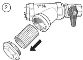
Secondary adjustment
Air is initially released from the hot water and venting may be necessary. If bubbling sounds can be heard from the heat pump, the circulation pump and radiators the entire system will require further venting. When the system is stable (correct pressure and all air eliminated) the automatic heating control system can be set as required
Start guide
NOTE
Fill in the climate system with water before the switch is set to " | "
- Set the control module's switch to "|".
- Follow the instructions in the start guide in the control module display. If the start guide does not start when you start the control module, start it manually in menu 5.7.
TIP
See page 63 for a more in-depth introduction to the installation's control system (operation, menus etc.).
Commissioning
The start guide is displayed when installation is started, It describes what needs to carry out at the first start together with basic settings during installation.
The start guide is displayed so that it cannot be bypassed in order to carry out the start-up correctly. You can start the start guide later in menu 5.7.
During the start-up guide, reversing valves and the shunt are run back and forth to help vent the heat pump.
CAUTION
As long as the start guide is active, no function in the heat pump will start automatically.
Each time the controller is ON, the guide will appear until it is completed on the last page.
Operation in the start guide
A. Page
B.Name and menu number

C. Option / setting
A. Page
You can see the current page of the start guide.
Scroll between the pages of the start guide as follows:
- Turn the control knob until the arrow is marked in the top left corner (at the page number).
- Press OK button to proceed to the next page in the start guide.
B. Name and menu number
You can see the menu name of this page. The number refers to the menu number in the control system.
To read more about affected menus, see the help menu or read the user manual.
C. Option / setting
Make settings for the system here.
D. Help menu

In many menus there is a symbol indicating that extra help is available.
To access the help text:
- Use the control knob to select the help symbol.
- Press OK button.
The help text often consists of several windows that you can scroll between using the control knob.
Heating/cooling curve setting

line
| outdoor temp. °C | flow temperature °C | |---|---| | -40 | 60 | | -30 | 55 | | -20 | 50 | | -10 | 45 | | 0 | 40 | | 10 | 35 | | 20 | 20 | | 30 | 15 | | 40 | 10 |
heating curve
Setting range: 0 - 15
Default value: 9
cooling curve (accessory required)
Setting range: 0 - 9
Default value: 0
The prescribed heating curve for your house can be viewed in the menu heating curve. The task of the heating curve is to give an even indoor temperature, regardless of the outdoor temperature, and thereby energy efficient operation. From this heating curve, the control module determines the temperature of the water to the heating system, supply temperature, and there by the indoor temperature. Select the heating curve and read off how the supply temperature changes at different outdoor temperatures here. If there is cooling function, the same settings can be made for the cooling curve.
Curve coefficient
The heating/cooling curve shows the relation between the target supply temperature and the corresponding outdoor temperature. A steep curve indicates that supply temperature becomes higher at low outdoor air temperature in heating and it becomes lower at high outdoor air temperature in cooling.

line
| Outdoor tempera | Supply temperature (°C) | | --------------- | ------------------------ | | 0 | 25 | | 10 | 35 | | 20 | 45 | | 30 | 55 | | -40 | 65 |The optimum slope depends on the climate conditions in your location, the type of heating device (radiators or under floor heating) and how well insulated the house is.
The curve is set when the heating installation is installed, but may need adjusting later. Normally, the curve will not need further adjustment.
CAUTION
In the event of making fine adjustments of the indoor temperature, the curve must be offset up or down instead, this is done in menu 1.1 temperature.
Curve offset
The target temperature can be off set in parallel over the entire outdoor temperature range by this function. This is offset by 5 °C by adjusting 2 steps.
The target temperature can be parallel offset in the entire outdoor temperature range with this function. It is offset by 5 °C by adjusting 2 steps.
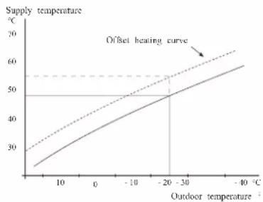
line
| Outdoor temperature (°C) | Supply temperature (°C) | | ------------------------ | ----------------------- | | 0 | 25 | | 10 | 35 | | 20 | 45 | | -20 | 50 | | -30 | 55 | | -40 | 60 |Flow line temperature – maximum and minimum values
This function is used in order to limit max-min supply temperature. The heating / cooling curve becomes fl at beyond max / min target temperature.
CAUTION
Underfloor heating systems are normally max flow line temperature set between 35 and 45°C. Take care not to cause low temperature burns in case it is set higher than 35°C.
Must be restricted with underfloor cooling min. flow line temp. to prevent condensation.
Check the max temperature for your floor with your installer/floor supplier.

The figure at the end of the curve indicates the curve number. The figure beside the thermometer icon gives the curve off set. Use the control knob to set a new value.
Confir rm the new setting by pressing the OK button.
Curve 0 is an own curve created in menu 1.9.7.
To select another curve (slope):
- Press OK button to access the setting mode
-
Select a new curve. The curves are numbered from 0 to 15, and the bigger number curve has steeper slope.
Curve 0 means that own curve (menu 1.9.7) is used. -
Press OK button to exit the setting.
To read off a curve:
- Turn the control knob so that the ring on the shaft with the outdoor temperature is marked.
- Press OK button.
- Follow the grey line up to the curve and out to the left to read off the value for the supply temperature at the selected outdoor temperature.
- You can now select to take read outs for different outdoor temperatures by turning the control knob to the right or left and read off the corresponding flow temperature.
- Press OK or Back button to exit read off mode.
TIP
Wait 24 hours before making a new setting, so that the room temperature has time to stabilise.
If it is cold outdoors and the room temperature is too low, increase the curve slope by one increment.
If it is cold outdoors and the room temperature is too high, lower the curve slope by one increment.
If it is warm outdoors and the room temperature is too low, increase the curve offset by one increment.
If it is warm outdoors and the room temperature is too high, lower the curve offset by one increment.
Hot water circulation setting
hot water recirc.
operating time
Setting range: 1 - 60 min
Default value: 60 min
downtime
Setting range: 0 – 60 min
Default value: 0 min
Set the hot water circulation for up to three periods per day here. During the set periods the hot water circulation pump will run according to the settings above.
"operating time" decide how long the hot water circulation pump must run per operating instance.
"downtime" decide how long the hot water circulation pump must be stationary between operating instances.
Hot water circulation is activated in menu 5.4 "soft inputs and outputs".
SG Ready
This function can only be used in mains networks that support the "SG Ready"-standard.
Make settings for the function "SG Ready" here.
Low price mode means that the electricity supplier has a low tariff and the system uses this to reduce costs.
Over capacity mode means that the electricity supplier has set the tariff very low and the system uses this to reduce the costs as much as possible.
affect room temperature
Here you set whether room temperature should be affected when activating "SG Ready".
With low price mode of "SG Ready" the parallel off set of the indoor temperature is increased by "+1". If a room sensor is installed and activated, the desired room temperature increases by 1 °C.
With over capacity mode of "SG Ready" the parallel off set for the indoor temperature is increased by "+2".
If a room sensor is installed and activated, the desired room temperature increases by 2 °C.
affect hot water
Here you set whether the temperature of the hot water should be affected when activating "SG Ready".
With low price mode on "SG Ready" the stop temperature of the hot water is set as high as possible at only compressor operation (immersion heater not permitted).
With over capacity mode of "SG Ready" the hot water is set to "luxury" (immersion heater permitted).
affect cooling (accessory required)
Here you set whether room temperature during cooling operation should be affected when activating "SG Ready".
With low price mode of "SG Ready" and cooling operation the indoor temperature is not affected.
With over capacity mode of "SG Ready" and cooling operation the parallel off set for the indoor temperature is reduced by"-1". If a room sensor is installed and activated, the desired room temperature decreases by 1 °C.
NOTE
The function must be connected to two AUX inputs and activated in menu 5.4.
Control Display unit
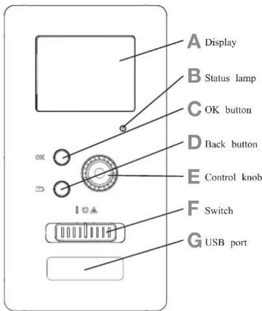
A Display
Instructions, settings and operational information are shown on the display. The easy-to-read display and menu system, make it easy to navigate between various menus and options, set comfort and get the necessary information.
B Status lamp
The status lamp indicates the status of the control module. It:
■ lights green during normal operation.
■ lights yellow in emergency mode.
■ lights red in the event of an alarm.
C OK button
The OK button is used to:
■ confirm selections of sub menus/options/set values/page in the start guide.
D Back button
The back button is used to:
■ go back to the previous menu.
■ change a setting that has not been confirmed.
E Control knob
The control knob can be turned to the right or left. You can:
■ scroll in menus and between options.
■ increase and decrease values.
■ change pages in multiple page instructions (for example help text and service info).
F Switch (SF1)
The switch shows three positions:
■ On ( | )
■ Standby ( ⏻ )
■ Emergency mode ( △ )
Emergency mode must only be used in the event of a fault on the control module. In this mode, the compressor in the heat pump is turned off and the immersion heater is activated.
The control module display is not illuminated and the status lamp lights yellow.
G USB port
The USB port is hidden behind the plastic badge of the product name.
The USB port is used to update the software.
Menu system

Menu 1 - INDOOR CLIMATE
Setting and scheduling the indoor climate. See information in the help menu or user manual.
Menu 2 - HOT WATER
Setting and scheduling hot water production. See information in the help menu or user manual.
This menu only appears if a water heater is installed in the system.
Menu 3 - INFO
Display of temperature and other operating information and access to the alarm log. See information in the help menu or user manual.
Menu 4 - MY INSTALLATION
Setting time, date, language, display, operating mode etc. See information in the help menu or user manual.
Menu 5 - SERVICE
Advanced settings. These settings are not available to the end user. The menu is made visible by pressing the Back button for 7 seconds in the top screen. See page 68 for details.
Symbols in the display
The following symbols can appear in the display during operation.
| Symbol Description | |
 | This symbol appears when there is information to be noticed in menu 3.1. |
 | These two symbols indicate whether the compressor in the outdoor unit or additional heat in the installation is blocked via controller.These functions will be blocked for example, when either of the operation mode is blocked in menu 4.2, when blocking of either function is scheduled in menu 4.9.5, or when an alarm for blocking the operation occurs.Blocking the compressor.Blocking additional heat. |
 | This symbol appears if periodic increase or lux mode for the hot water is activated. |
 | This symbol indicates if "holiday setting" is active in menu 4.7. |
 | This symbol indicates if the controller has contact with myUpway. |
| [GGBD] | This symbol indicates if cooling is active. |

flowchart
graph LR
    A["Menu number – marked sub menu"] --> B["Symbol – main menu"]
    B --> C["INDOOR CLIMATE"]
    C --> D["Hot Water"]
    D --> E["My INSTALLATION"]
    E --> F["INDOOR CLIMATE"]
    F --> G["Marked main menu"]
    G --> H["Symbols – sub menus"]
    H --> I["Name – sub menus"]
    I --> J["Status information – sub menus"]
    J --> K["symbols – sub menus"]
    K --> L["INDEX: 1.1"]
    L --> M["scheduling off"]
    L --> N["advanced"]
Operation
To move the cursor, turn the control knob to the left or the right. The marked position is brighter and/or has a light frame.
Selecting menu
To advance in the menu system select a main menu by marking it and then pressing the OK button. A new window opens with sub menus.
Select one of the sub menus by marking it and then pressing the OK button.
Selecting options

Alternative
In an options menu the current selected option is indicated by a green tick.

To select another option:
- Mark the applicable option. One of the options is pre-selected (white).

- Press the OK button to confirm the selected option. The selected option has a green tick.

Setting a value
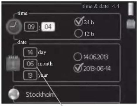
Values to be changed
To set a value:
- Mark the value you want to set using the control knob.

- Press the OK button. The background of the value becomes green, which means that you have accessed the setting mode.

- Turn the control knob to the right to increase the value and to the left to reduce the value.

- Press the OK button to confirm the value you have set. To change and return to the original value, press the Back button.

Use the virtual keyboard

In some menus where text may require entering, a virtual keyboard is available.
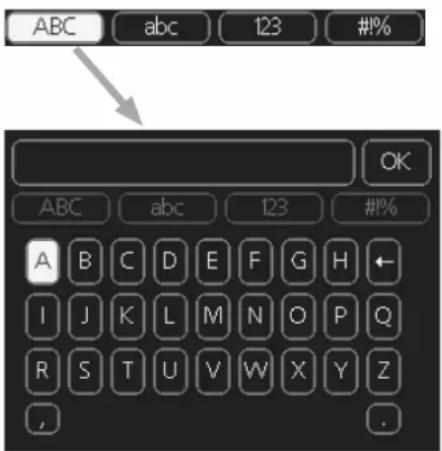
Depending on the menu, you can gain access to different character sets which you can select using the control knob. To change character table, press the Back button. If a menu only has one character set, the keyboard is displayed directly.
When you have finished writing, mark "OK" and press the OK button.
Scroll through the windows
A menu can consist of several windows. Turn the control knob to scroll between the windows.

Scroll through the windows in the start guide

- Turn the control knob until one of the arrows in the top left corner (at the page number) has been marked.
- Press the OK button to skip between the steps in the start guide.
Help menu
In many menus there is a symbol that indicates that extra help is available.
To access the help text:
- Use the control knob to select the help symbol.
- Press the OK button.
The help text often consists of several windows that you can scroll between using the control knob.
Menu list
"* Accessories are needed. ** Heat pump with cooling function required. 40"
| MENU RC-HY20 RC-HY40 | ||||
| 1 INDOOR CLIMATE | ||||
| 1.1 - temperature 1.1.1 heating | ✓ | ✓ | ||
| 1.1.2 cooling ** | ✓ | ✓ | ||
| 1.3 - scheduling 1.3.1 heating | ✓ | ✓ | ||
| 1.3.2 cooling ** | ✓ | ✓ | ||
| 1.9 - advanced 1.9.1 curve 1.9.1.1 | heating curve | ✓ | ✓ | |
| 1.9.1.2 cooling curve ** | ✓ | ✓ | ||
| 1.9.2 external adjustment | ✓ | ✓ | ||
| 1.9.3 min. flow line temp. 1.9.3 | 1 heating | ✓ | ✓ | |
| 1.9.3.2 cooling ** | ✓ | ✓ | ||
| 1.9.4 room sensor settings | ✓ | ✓ | ||
| 1.9.5 cooling settings * | ✓ | ✓ | ||
| 1.9.7 own curve 1.9.7.1 heating | ✓ | ✓ | ||
| 1.9.7.2 cooling ** | ✓ | ✓ | ||
| 1.9.8 point off set | ✓ | ✓ | ||
| 2 HOTWATER | ||||
| 2.1 temporary lux | ✓ | ✓ | ||
| 2.2 comfort mode | ✓ | ✓ | ||
| 2.3 scheduling | ✓ | ✓ | ||
| 2.9 advanced 2.9.1 periodic increase | ✓ | ✓ | ||
| 2.9.2 hot water recirc. * | ✓ | ✓ | ||
| 3 INFO | ||||
| 3.1 service info | ✓ | ✓ | ||
| 3.2 compressor info | ✓ | ✓ | ||
| 3.3 add. heat info | ✓ | ✓ | ||
| 3.4 alarm log | ✓ | ✓ | ||
| 3.5 indoor temp. log | ✓ | ✓ | ||
| 4. MY SYSTEM | ||||
| 4.1 plus functions 4.1.3 internet 4.1.3.1 myUpwayTM | ✓ | ✓ | ||
| 4.1.3.8 tcp/ip settings | ✓ | ✓ | ||
| 4.1.3.9 proxy settings | ✓ | ✓ | ||
| 4.1.5 SG Ready | ✓ | ✓ | ||
| 4.1.6 smart price adaptionTM | ✓ | ✓ | ||
| 4.1.8 smart energy sourceTM | 4.1.8.1 settings | - | ||
| 4.1.8.2 set. Price | - | |||
| 4.1.8.3 CO2 impact | - | |||
| 4.1.8.4 tariff periods, electricity | - | |||
| 4.1.8.6 tariff per, ext. shunt add | - | |||
| 4.1.8.7 tariff per, ext. step add | - | |||
| 4.2 op. mode | ✓ | ✓ | ||
| 4.3 my icons | ✓ | ✓ | ||
| 4.4 time & date | ✓ | ✓ | ||
"* Accessories are needed. ** Heat pump with cooling function required. 40"
| MENU RC-HY20 RC-HY40 | ||||
| 4.6 language | ✓ | ✓ | ||
| 4.7 holiday setting | ✓ | ✓ | ||
| 4.9 advanced 4.9.1 op. prioritisation | ✓ | ✓ | ||
| 4.9.2 auto mode setting | ✓ | ✓ | ||
| 4.9.3 degree minute setting | ✓ | ✓ | ||
| 4.9.4 factory setting user | ✓ | ✓ | ||
| 4.9.5 schedule blocking | ✓ | ✓ | ||
| 4.9.6 schedule silent mode | ✓ | ✓ | ||
| 5 SERVICE | ||||
| 5.1 operating settings 5.1.1 hot water settings * | ✓ | ✓ | ||
| 5.1.2 max flow line temperature | ✓ | |||
| 5.1.3 max diff flow line temp. | ✓ | |||
| 5.1.4 alarm actions | ✓ | |||
| 5.1.12 addition | ✓ | |||
| 5.1.14 flow set climate system | ✓ | |||
| 5.1.22 heat pump testing | ✓ | |||
| 5.1.23 compressor curve | ✓ | |||
| 5.2 system settings 5.2.2 installed slaves | ✓ | ✓ | ||
| 5.2.3 docking | ✓ | |||
| ✓ | ||||
| 5.2.4 accessories | controlled add. heat * | - | ||
| 5.3.3 extra climate system * | - | |||
| 5.3.6 step controlled add. Heat | - | |||
| 5.3.8 hot water comfort * | - | |||
| 5.3.20 flow sensor* | - | |||
| 5.4 soft in/outputs | ✓ | ✓ | ||
| 5.5 factory setting service | ✓ | ✓ | ||
| 5.6 forced control | ✓ | ✓ | ||
| 5.7 start guide | ✓ | ✓ | ||
| 5.8 quick start | ✓ | ✓ | ||
| 5.9 floor drying function | ✓ | ✓ | ||
| 5.10 change log | ✓ | ✓ | ||
| 5.11 slave settings 5.11.1 EB101 | 5.11.1.1 heat pump | ✓ | ✓ | |
| 5.11.1.2 charge pump (GP12) | ✓ | ✓ | ||
| 5.11.2 EB102 | - | ✓ | ||
| 5.11.3 EB103 | - | ✓ | ||
| 5.11.4 EB104 | - | ✓ | ||
| 5.11.5 EB105 | - | ✓ | ||
| 5.11.6 EB106 | - | ✓ | ||
| 5.11.7 EB107 | - | ✓ | ||
| 5.11.8 EB108 | - | ✓ | ||
| 5.12 country | ✓ | ✓ | ||
Sub-menus
Menu SERVICE has orange text and is intended for the advanced user. This menu has several sub-menus.
Status information for the relevant menu can be found on the display to the right of the menus.
operating settings: Operating settings for the control module.
system settings: System settings for the control module, activating accessories etc.
soft in/outputs: Setting software controlled in and outputs on the input card (AA3) and terminal block (X2).
factory setting service: Total reset of all settings (including settings available to the user) to default values.
forced control: Forced control of the different components in the indoor module.
start guide: Manual start of the start guide which is run the first time when the control module is started.
quick start: Quick starting the compressor.
NOTE
Incorrect settings in the service menus can damage the installation.
Menu 5.1 - operating settings
Operating settings can be made for the control module in the sub menus.
Menu 5.1.1 - hot water settings
economy
Setting range start temp. economy: 5 - 55 °C
Factory setting start temp. economy: 42 °C
Setting range stop temp. economy: 5 - 60 °C
Factory setting stop temp. economy: 48 °C
normal
Setting range start temp. normal: 5 - 60 °C
Factory setting start temp. normal: 46 °C
Setting range stop temp. normal: 5 - 65 °C
Factory setting stop temp. normal: 50 °C
luxury
Setting range start temp. lux: 5 - 70 °C
Factory setting start temp. lux: 49 °C
Setting range stop temp. lux: 5 - 70 °C
Factory setting stop temp. lux: 53 °C
stop temp. per. increase
Setting range: 55 – 70 °C
Factory setting: 55 °C
charge method
Setting range: target temp, delta temp
Default value: delta temp
Here you set the start and stop temperature of the hot water for the different comfort options in menu 2.2 as well as the stop temperature for periodic increase in menu 2.9.1.
The charge method for hot water mode is selected here. "delta temp" is recommended for heaters with charge coil, "target temp" for heaters with domestic coil.
Menu 5.1.2 - max flow line temperature
climate system
Setting range: 5 - 70 °C
Default value: 60 °C
Set the maximum supply temperature for the climate system here. If the installation has more than one climate system, individual maximum supply temperatures can be set for each system. Climate systems 2 – 8 cannot be set to a higher max supply temperature than climate system 1.
CAUTION
Underfloor heating systems are normally max flow line temperature set between 35 and 45°C.
Be careful not to cause low temperature burn if it is set at 35^ C or higher.
Check the max floor temperature with your floor supplier.
Menu 5.1.3 - max diff flow line temp.
max diff compressor
Setting range: 1 - 25 °C
Default value: 10 °C
max diff addition
Setting range: 1 - 24 °C
Default value: 7 °C
Here you set the maximum permitted difference between the calculated and actual supply temperature during compressor mode and add. heat mode. Max diff. additional heat can never exceed max diff. compressor
max diff compressor
When the current supply temperature deviates from the set value compared to that calculated, the heat pump is forced to stop irrespective of the degreeminute value.
If the current supply temperature exceeds the calculated flow temperature plus the set value, the degree minute value is set to 0. The compressor in the heat pump stops when there is only a heating demand.
max diff addition
If "addition" is selected and activated in menu 4.2 and the present supply temp exceeds the calculated temperature plus the set value, the additional heat is forced to stop.
Menu 5.1.4 - alarm actions
Select how to control the heat pump in the event of an alarm. You can choose to stop producing hot water and/or reduce the room temperature.
CAUTION
If no alarm action is selected, it can result in higher energy consumption in the event of an alarm.
Menu 5.1.12 - addition
add type: step controlled
max step
Setting range (binary stepping deactivated): 0 - 3
Setting range (binary stepping activated): 0 - 7
Default value: 3
fuse size
Setting range: 1 - 200 A
Factory setting: 16 A
You can set the maximum number of permitted additional heat steps, if there is internal additional heat in the tank (only accessible if the additional heat is positioned after QN10), whether binary stepping is to be used and the size of the fuse.
prioritised additional heat
Setting range: on/off
Factory setting: off
minimum running time
Setting range: 0 – 48 h
Default value: 12 h
min temp.
Setting range: 5 – 90 °C
Default value: 55 °C
mixing valve amplifier
Setting range: 0.1 - 10.0
Default value: 1.0
mixing valve step delay
Setting range: 10 - 300 s
Default values: 30 s
fuse size
Setting range: 1 - 200 A
Factory setting: 16 A
transformation ratio
Setting range: 300 - 3000
Factory setting: 300
Select this option if shunt controlled additional heat is connected.
Set when the addition is to start, the minimum run time and the minimum temperature for external addition with shunt here. External addition with shunt is for example a wood/oil/gas/pellet boiler.
You can set shunt valve amplification and shunt valve waiting time.
Selecting "prioritised additional heat" uses the heat from the external additional heat instead of the heat pump.
The shunt valve is regulated as long as heat is available, otherwise the shunt valve is closed.
TIP
See the accessory installation instructions for function description.
Menu 5.1.14 - flow set. climate system
presettings
Setting range: radiator, fl oor heat., rad. + fl oor heat.
Default value: radiator
Setting range DOT: -40.0 – 20.0 °C
The factory setting of DOT value depends on the country that has been given for the product's location.
The example below refers to Sweden.
Factory setting DOT: -20.0 °C
own setting
Setting range dT at DOT: 0.0 - 25.0
Factory setting dT at DOT: 10.0
Setting range DOT: -40.0 - 20.0 °C
Factory setting DOT: -20.0 °C
Select the type of heating distribution system.
dT at DOT is the difference in degrees between flow and return temperatures at dimensioned outdoor temperature.
Menu 5.1.22 - heat pump testing
NOTE
This menu is intended for testing heat pump according to different standards.
Use of this menu for other reasons may result in your installation not functioning as intended.
This menu contains several sub-menus, one for each standard.
Menu 5.1.23 - compressor curve
Set whether the compressor in the heat pump should work to a particular curve under specific requirements or if it should work to predefined curves.
You can set a curve for each operation mode (heat, hot water, coolingetc.) by unticking "auto", turning the control knob until a temperature is marked and pressing OK. You can set at what temperature max- min frequencies will occur.
This menu consists of several windows (one for each operation mode). Use the navigation arrow in the top left corner to change between the windows.
Menu 5.2 - system settings
Make different system settings for your installation here, e.g. activate the connected heat pump and which accessories are installed.
Menu 5.2.2 - installed heat pump
If a heat pump is connected to the master installation, set it here.
For RC-HY40, you can set slave unit to be connected.
There are two ways of activating connected slaves. You can either mark the alternative in the list or use the automatic function "search installed slaves".
search installed slaves
Mark "search installed slaves" and press the OK button to automatically find connected slaves for the master heat pump.
Menu 5.2.3 - docking (RC-HY 40 only)
Enter how your system is docked regarding pipes, for example to hot water heating and heating the building.
This menu has a docking memory which means that the control system remembers how a particular reversing valve is docked and automatically enters the correct docking the next time you use the same reversing valve.
Workspace for dockingSlave (heat pump)

Marking frameCompressor
Slave: Here you select for which heat pump the docking setting is to be made.
Compressor: Select if the compressor in the heat pump is blocked (factory setting), or standard (docked for example to pool heating, hot water charging and heating the building).
Marking frame: Move around the marking frame using the control knob. Use the OK button to select what you want to change and to confirm setting in the options box that appears to the right.
Workspace for docking: The system docking is drawn here.
| Symbol | Description |
 | Compressor (blocked) |
 | Compressor (standard) |
 | Reversing valves for hot water, cooling.The designations above the reversing valve indicate where it is electrically connected (EB101 = Slave 1, etc.). |
 | Hot water charging |
 | Heating (heating the building, includes any extra climate system) |
 | Cooling |
Menu 5.2.4 - accessories
Set which accessories are installed on the installation here.
If the water heater is connected, hot water charging must be activated here.
Menu 5.3 - accessory settings
The operating settings for accessories that are installed and activated are made in the sub-menus for this.
Menu 5.3.2 - shunt controlled add. Heat
prioritised additional heat
Setting range: on/off
Factory setting: off
start diff additional heat
Setting range: 0 - 2000 GM
Default values: 400 GM
minimum running time
Setting range: 0 – 48 h
Default value: 12 h
min temp.
Setting range: 5 – 90 °C
Default value: 55 °C
mixing valve amplifier
Setting range: 0.1 - 10.0
Default value: 1.0
mixing valve step delay
Setting range: 10 - 300 s
Default values: 30 s
Set when the addition is to start, the minimum run time and the minimum temperature for external addition with shunt here.
External addition with shunt is for example a wood/oil/gas/pellet boiler.
You can set shunt valve amplification and shunt valve waiting time.
Selecting "prioritised additional heat" uses the heat from the external additional heat instead of the heat pump.
The shunt valve is regulated as long as heat is available, otherwise the shunt valve is closed.
See the accessory installation instructions for function description.
Menu 5.3.3 - extra climate system
use in heating mode
Setting range: on/off
Factory setting: on
use in cooling mode
Setting range: on/off
Factory setting: off
mixing valve amplifier
Setting range: 0.1 - 10.0
Default value: 1.0
mixing valve step delay
Setting range: 10 - 300 s
Default values: 30 s
Here you select which climate system (2 - 8) you wish to set.
In the next menu you can make settings for the climate system
that you have selected. If this function is activated, you can set "cooling flow temp. at +20°C" and "cooling flow temp. at +40°C" for each climate system where the function is activated.
CAUTION
This setting option only appears if "cooling permitted" is activated in menu 5.11.1.1.
The shunt amplifi cation and shunt waiting time for the diff erent extra climate systems that are installed are also set here.
See the accessory installation instructions for function description.
Menu 5.3.6 - step controlled add. heat
start addition
Setting range: 0 - 2000 GM
Default values: 400 GM
diff. between additional steps
Setting range: 0 - 1000 GM
Default values: 30 GM
max step
Setting range
(binary stepping deactivated): 0 - 3
Setting range
(binary stepping activated): 0 - 7
Default value: 3
binary stepping
Setting range: on/off
Factory setting: off
Make settings for step controlled addition here. Step controlled addition is for example an external electric boiler.
It is possible, for example, to select when the additional heat is to start, to set the maximum number of permitted steps and whether binary stepping is to be used.
When binary stepping is deactivated (off), the settings refer to linear stepping.
See the accessory installation instructions for function description.
Menu 5.3.8 - hot water comfort
activating imm heater
Setting range: on/off
Factory setting: off
activ. imm heat in heat mode
Setting range: on/off
Factory setting: off
activating the mixing valve
Setting range: on/off
Factory setting: off
outgoing hot water
Setting range: 40 – 65 °C
Default value: 55 °C
mixing valve amplifier
Setting range: 0.1 - 10.0
Default value: 1.0
mixing valve step delay
Setting range: 10 - 300 s
Default values: 30 s
Make settings for the hot water comfort here.
See the accessory installation instructions for function description.
activating imm heater: The immersion heater is activated here if installed in the water heater.
activ. imm heat in heat mode: Activate here whether the immersion heater in the tank (required if the alternative above is activated) will be permitted to charge hot water, if the compressors in the heat pump prioritise heating.
activating the mixing valve: Activate here whether a mixer valve for limiting the temperature of hot water from the water heater is installed.
If this alternative has been activated, you can set the outgoing hot water temperature, shunt amplification and shunt waiting time for the mixer valve.
outgoing hot water: Set the temperature at which the mixing valve is to restrict hot water from the water heater.
See the accessory installation instructions for function description.
Menu 5.3.20 - flow sensor

flow sensor
Setting option: EMK 500, EMK 310 / 300, EMK 150
Factory setting: EMK 500
Here you select which flow sensor is used for the energy measurement.
Menu 5.4 - soft in/outputs
You can set the function of in/output for each terminal (AUX1-6 and output).
Position of the terminal depends on the type of controller.
RC-HY20: port 11-18 on X2 terminal (AUX1-6), X4 terminal on AA2 board (output)
RC-HY40: port 9-14 on terminal X6 and port 1-4 on X2 terminal on AA3 board (AUX1-6), X7 terminal on AA3 board (output)
Menu 5.5 - factory setting service
All settings can be reset (including settings available to the user) to default values here.
NOTE
When resetting, the start guide is displayed the next time the control module is restarted.
Menu 5.6 - forced control
You can force control the different components in the control module and any connected accessories here.
Menu 5.7 - start guide
When the control module is started for the first time the start guide starts automatically. Start it manually here.
See page 25 for more information about the start guide.
Menu 5.8 - quick start
It is possible to start the compressor from here.
CAUTION
There must be a heating or hot water demand to start the compressor.
CAUTION
Do not quick start the compressor too many times over a short period of time as this may damage the compressor and its surrounding equipment.
Menu 5.9 - floor drying function
length of period 1 - 7
Setting range: 0 - 30 days
Factory setting, period 1 – 3, 5 – 7: 2 days
Factory setting, period 4: 3 days
temp. period 1 – 7
Setting range: 15 - 70 °C
Default value:
| temp. period 1 | 20 °C |
| temp. period 2 | 30 °C |
| temp. period 3 | 40 °C |
| temp. period 4 | 45 C |
| temp. period 5 | 40 °C |
| temp. period 6 | 30 °C |
| temp. period 7 | 20 °C |
Set the function for under floor drying here.
You can set up to seven period times with different calculated flow temperatures. If less than seven periods
are to be used, set the remaining period times to 0 days.
Mark the active window to activate the underfloor drying function. A counter at the bottom shows the number of days the function has been active.
TIP
If operating mode "add. heat only" is to be used, select it in menu 4.2.
Menu 5.10 - change log
Read off any previous changes to the control system here.
The date, time and ID no. (unique to certain settings) and the new set value is shown for every change.
NOTE
The change log is saved at restart and remains unchanged after factory setting.
Menu 5.11 - heat pump settings
Settings for installed heat pump can be made in the submenus.
Menu 5.11.1 - EB101 - EB108
Make settings specifically for the installed heat pump and charge pump here.
For RC-HY40, it is possible to connect up to 8 heat pumps.
Menu 5.11.1.1 - heat pump
Make settings for the installed heat pump here. To see what settings you can make, see installation manual for the heat pump.
Menu 5.11.1.2 - charge pump (GP12)
op. mode
Heating/cooling
Setting range: auto / intermittent
Default value: auto
Set the operating mode for the charge pump here.
auto: The charge pump runs according to the current operating mode for SMO 20.
intermittent: The charge pump starts and stops 20 seconds before and after the compressor in the heat pump.
speed during operation heating, hot water, cooling
Setting range: auto / manual
Default value: auto
Manual setting
Setting range: 1 - 100 %
Default values: 70 %
speed in wait mode
Setting range: 1 - 100 %
Default values: 30 %
max. allowed speed
Setting range: 80 - 100 %
Default values: 100 %
Set the speed at which the charge pump is to operate in the present operating mode. Select "auto" if the speed of the charge pump is to be regulated automatically (factory setting) for optimal operation.
If "auto" is activated for heating operation, you can also make the setting "max. allowed speed" which restricts the charge pump and does not allow it to run at a higher speed than the set value.
For manual operation of the charge pump deactivate "auto" for the current operating mode and set the value to between 1 and 100 % (the previously set value for "max. allowed speed" no longer applies).
Speed in standby mode (only used if "auto" has been selected for "Operating mode") means the charge pump operates at the set speed during the time when there is neither a need for compressor operation nor additional heat.
5.12 - country
Select here where the product was installed. This allows access to country specific settings in your product.
Language settings can be made regardless of this selection.
NOTE
This option locks after 24 hours, restart of display or program updating.
Service
Service actions
NOTE
Servicing should only be carried out by persons with the necessary expertise.
When replacing components on the system, only genuine replacement parts may be used.
NOTE
If an electrical connection has been disconnected and is connected, ground must be checked using a suitable multimeter.
Maintenance
General inspection
Check the following:
- Condition of casing.
- Electrical connections.
- Alarm log.
Correct any fault before continuing.
Climate system
Check the following:
- Climate system start and stop temperature.
- Heating curve settings.
- Function of the room sensor (if installed).
- System pressure.
- Flow and return temperature. The difference must be 5-10 °C.
Correct any fault before continuing.
Emergency mode
NOTE
Switch (SF1) must not be put into mode "I" or △ before the installation is filled with water. The compressor in the heat pump can be damaged.
Emergency mode is used in event of operational interference and in conjunction with service. Hot water is not produced in emergency mode.
Emergency mode is activated by setting switch (SF1) in mode "△". This means that:
■ The status lamp illuminates yellow.
■ The display is not lit and the control computer is not connected.
■ Hot water is not produced.
■ The compressors are switched off. Charge pump (EB101-GP12) is running.
■ The heating medium pump is active.
■ The emergency mode relay (K1) is active.
External additional heat is active if it is connected to the emergency mode relay (K1, terminal block X1).
Ensure that the heating medium circulates through the external additional heat.
Temperature sensor data
| Temperature (°C) | Resistance (kOhm) | Voltage (VDC) |
| -40 351.0 3.256 | ||
| -35 251.6 3.240 | ||
| -30 182.5 3.218 | ||
| -25 133.8 3.189 | ||
| -20 99.22 3.150 | ||
| -15 74.32 3.105 | ||
| -10 56.20 3.047 | ||
| -5 42.89 2.976 | ||
| 0 33.02 2.889 | ||
| 5 25.61 2.789 | ||
| 10 20.02 2.673 | ||
| 15 15.77 2.541 | ||
| 20 12.51 2.399 | ||
| 25 10.00 2.245 | ||
| 30 8.045 2.083 | ||
| 35 6.514 1.916 | ||
| 40 5.306 1.752 | ||
| 45 4.348 1.587 | ||
| 50 3.583 1.426 | ||
| 55 2.968 1.278 | ||
| 60 2.467 1.136 | ||
| 65 2.068 1.007 | ||
| 70 1.739 0.891 | ||
| 75 1.469 0.785 | ||
| 80 1.246 0.691 | ||
| 85 1.061 0.607 | ||
| 90 0.908 0.533 | ||
| 95 0.779 0.469 | ||
| 100 0.672 0.414 |
USB service outlet

natural_image
Line drawing of a device with ports and an attached USB port, no text or symbols presentRC-HY20/40 is equipped with a USB socket in the display unit. This USB socket can be used to connect a USB memory to update the software, save logged information and handle the settings in RC-HY20/40.

When a USB memory is connected a new menu (menu 7) appears in the display.
Menu 7.1 - update firmware
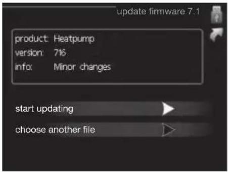
This allows you to update the software in RC-HY20/40.
NOTE
For the following functions to work the USB memory must contain files with software for RC-HY20/40.
This information states which product the software is intended for, the software version and general information about them. If you wish to select another file than the one selected, the correct file can be selected by "choose another file".
start updating
Select "start updating" if you want to start the update.
You are asked whether you really want to update the software. Respond "yes" to continue or "no" to undo.
If you responded "yes" to the previous question the update starts and you can now follow the progress of the update on the display. When the update is complete RC-HY20/40 restarts.
NOTE
A software update does not reset the menu settings in RC-HY20/40.
NOTE
If the update is interrupted before it is complete (for example power cut etc.) the software can be reset to the previous version if the OK button is kept pressing during start up until the green lamp starts to illuminate (takes about 10 seconds).
choose another file

Select "choose another file" if you do not want to use the suggested software. When you scroll through the files, information about the marked software is shown in a fact box just as before. When you have selected a file with the OK button you will return to the previous page (menu 7.1) where you can choose to start the update.
Menu 7.2 - logging

Setting range: 1 s - 60 min
Factory setting range: 5 s
You can set the interval of the log data storage and start saving the log data on the USB memory.
- Set the desired interval between loggings.
- Tick "activated".
- The present values from RC-HY20/40 are saved in a file in the USB memory at the set interval until "activated" is unticked.
NOTE
Untick "activated" before removing the USB memory. Menu 7.3 - manage settings
Menu 7.3 - manage settings

Here you can manage (save as or retrieve from) all the menu settings (user and service menus) in RC-HY20/40 with a USB memory.
Via "save settings" you save the menu settings to the USB memory in order to restore them later or to copy the settings to another RC-HY20/40.
NOTE
When you save the menu settings to the USB memory you replace any previously saved settings on the USB memory.
Via "recover settings" you reset all menu settings from the USB memory.
NOTE
Reset of the menu settings from the USB memory cannot be undone.
Disturbance in comfort
In most cases, the control module notes a malfunction and indicates this with alarms and shows instructions to rectify it in the display. See "Manage alarm" for in- formation about managing alarms. If the malfunction does not appear in the display, or if the display is not lit, the following troubleshooting guide can be used.
Manage alarm
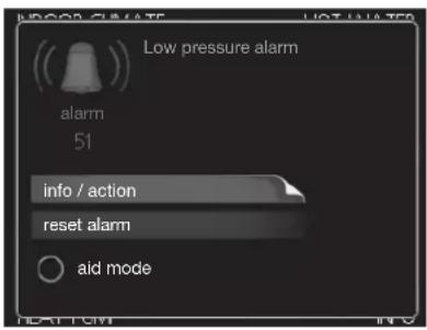
In the event of an alarm, some kind of malfunction has occurred, which is indicated by the status lamp changing from green continuously to red continuously. In addition, an alarm bell appears in the information window.
Alarm
In the event of an alarm with a red status lamp a malfunction has occurred that the heat pump and/or control module cannot remedy itself. In the display, by turning the control knob and pressing the OK button, you can see the type of alarm it is and reset it. You can also choose to set the installation to aid mode.
info / action Here you can read what the alarm means and receive tips on what you can do to correct the problem that caused the alarm.
reset alarm In most cases it is enough to select "reset alarm" to correct the problem that caused the alarm. If a green light illuminates after selecting "reset alarm" the alarm has been remedied. If a red light is still visible and a menu called "alarm" is visible in the display, the problem that caused the alarm remains. If the alarm disappears and then returns, see the troubleshooting section (page 78 and 79).
aid mode "aid mode" is a type of emergency mode. This means that the installation produces heat and/or hot water despite there being some kind of problem. This can mean that the heat pump's compressor is not running. In this case any electrical addition produces heat and/or hot water.
NOTE
To select aid mode an alarm action must be selected in the menu 5.1.4.
CAUTION
Selecting "aid mode" is not the same as correcting the problem that caused the alarm. The status lamp will therefore continue to be red.
Troubleshooting
If the operational interference is not shown in the display the following tips can be used:
Basic actions
Start by checking the following possible fault sources:
■ The switch's (SF1) position.
■ Group and main fuses of the accommodation.
■ The property's earth circuit breaker.
■ The control module's miniature circuit breaker (FA1).
Low hot water temperature or a lack of hot water
This part of the fault-tracing chapter only applies if the water heater is installed in the system.
■ Closed or choked fi lling valve for the hot water heater.
- Open the valve.
■ Mixing valve (if there is one installed) set too low.
- Adjust the mixer valve.
■ Control module in incorrect operating mode.
- If mode "manual" is selected, select "addition".
■ Large hot water consumption.
- Wait until the hot water has heated up. Temporarily increased hot water capacity (temporary lux) can be activated in menu 2.1.
■ Too low hot water setting.
- Enter menu 2.2 and select a higher comfort mode.
■ Too low or no operating prioritisation of hot water.
- Enter menu 4.9.1 and increase the time for when hot water is to be prioritised.
Low room temperature
■ Closed thermostats in several rooms.
- Set the thermostats to max, in as many rooms as possible. Adjust the room temperature via menu 1.1, instead of choking the thermostats.
■ Control module in incorrect operating mode.
— Enter menu 4.2. If mode "auto" is selected, select a higher value on "stop heating" in menu 4.9.2.
- If mode "manual" is selected, select "heating". If this is not enough, select "addition".
■ Too low set value on the automatic heating control.
- Enter menu 1.1 "temperature" and adjust the offset heating curve up. If the room temperature is only low in cold weather the curve slope in menu 1.9.1 "heating curve" needs adjusting up.
■ Too low or no operating prioritisation of heat.
- Enter menu 4.9.1 and increase the time for when heating is to be prioritised.
■ "Holiday mode" activated in menu 4.7.
- Enter menu 4.7 and select "Off".
■ External switch for changing the room heating activated.
- Check any external switches.
■ Air in the climate system.
- Vent the climate system.
■ Closed valves to the climate system.
- Open the valves.
■ Incorrectly adjusted flow across the heat pump.
- Check whether alarm high condenser in (163) or high condenser out (162) is in the alarm log. Follow the instructions for adjusting charge flow.
High room temperature
■ Too high set value on the automatic heating control.
- Enter menu 1.1 (temperature) and reduce the offset heating curve. If the room temperature is only high in cold weather the curve slope in menu 1.9.1 "heating curve" needs adjusting down.
■ External switch for changing the room heating activated.
- Check any external switches.
Low system pressure
■ Not enough water in the climate system.
- Top up the water in the climate system.
The compressor does not start
■ There is no heating requirement.
- The heat pump does not call on heating nor hot water.
■ Temperature conditions tripped.
- Wait until the temperature condition has been re-set.
■ Minimum time between compressor starts has not been reached.
- Wait 30 minutes and check if the compressor has started.
■ Alarm tripped.
– Follow the display instructions.
Additional heating only
If you are unsuccessful in rectifying the fault and are unable to heat the house, you can, whilst waiting for assistance, continue running the heat pump in "add. heat only". This means that additional heating only is used to heat the house.
Set the installation to additional heat mode
- Go to menu 4.2 op. mode.
- Mark "add. heat only" using the control knob and then press OK button.
Return to the main menus by pressing the Back button.
CAUTION
When commissioning without MTH air/water heat pump an alarm communication error may appear in the display.
The alarm is reset if the relevant heat pump is deactivated in menu 5.2.2 ("installed heat pump").
Alarm list
| Alarm nr. | Alarm text on the display | Description May be due to | |
| 157 Low | Ip cooling Protection against freezing in water HX during cooling operation | ■ Low/no water flow | |
| 162 High | condenser out temperature | Too high temperature out from the condenser. Self-resetting. | ■ Low flow during heating operation■ Too high set temperatures |
| 163 High | condenser in temperature | Too high temperature into the condenser. Self-resetting. | ■ Temperature generated by another heat source |
| 183 Defrosting in progress Not an alarm, but an operating status. ■ Set when the heat pump runs the defrosting procedure | |||
| 220 High | pressure alarm BP4 has been above 4,15MPa 5 times within 60 minutes. | ■ Insuffi cient air circulation or blocked heat exchanger■ Expansion valve not correctly connected■ Service valve closed■ Defective control board in FDCW■ Low or no flow during heating operation■ Defective circulation pump■ Defective fuse, F(4A) | |
| 224 Fan alarm from heat pump | Deviations in the fan speed in FDCW. ■ The fan cannot rotate freely■ Defective control board in FDCW■ Defective fan motor■ Control board in FDCW dirty■ Fuse (F2) blown | ||
| 228 | Failed defrosting | 10 aborted defrost due to alarm: 418,419 or 343 | ■ Too low water flow■ Too low return temperatur |
| 230 Hot gas alarm | Temperature deviation on the hot gas sensor (Tho-D) twice within 60 minutes or for 60 minutes continuously. | ■ Sensor does not work (see section "Ambient temperature sensor")■ Insuffi cient air circulation or heat exchanger■ Blocked■ If the fault persists during cooling, there may be an insufficient amount of refrigerant.■ Defective control board in FDCW | |
| 261 High | IWX temp Temperature deviation on the heat exchanger sensor (Tho-R1/R2) fi ve times within 60 minutes or for 60 minutes continuously. | ■ Sensor does not work (see section "Disturbances in comfort")■ Insuffi cient air circulation or blocked heat exchanger■ Defective control board in FDCW■ Too much refrigerant | |
| 262 Inv. err. | When IPM (Intelligent power module) displays FO-signal (Fault Output) fi ve times during a 60-minute period. | Can occur when 15V power supply to the inverter PCB is unstable. | |
| 263 Inv. err. | Voltage from the inverter outside the parameters four times within 30 minutes. | ■ Incoming power supply interference■ Service valve closed■ Insuffi cient amount of refrigerant■ Compressor fault■ Defective circuit board in FDCW | |
| 265 Inv. err. | Continuous deviation on power transistor for 15 minutes. | ■ Defective fan motor■ Defective circuit board in FDCW | |
| 267 Inv. err. | Failed start for compressor ■ Defective circuit board in FDCW | ■ Defective control board in FDCW■ Compressor fault | |
| 268 Inv. err. | Overcurrent, Inverter A/F module ■ Sudden power failure | ||
| 271 Lw old tmp Temperature of BT28 below the value that permits operation | ■ Cold weather conditions■ Sensor fault | ||
| 272 High otd tmp Temperature of BT28 above the value that permits operation | ■ Warm weather conditions■ Sensor fault | ||
| 277 Sensor fault from heat pump | Sensor fault, heat exchanger in FDCW(Tho-R). ■ Open circuit or short circuit on sensor input■ Sensor does not work (see section "Disturbances in comfort")■ Defective control board in FDCW | ||
| 278 Sensor fault from heat pump | Sensor fault, outdoor temperature sensor in FDCW (Tho-A). | ■ Open circuit or short circuit on sensor input■ Sensor does not work (see section "Disturbances in comfort")■ Defective control board in FDCW | |
| 279 Sensor fault from heat pump | Sensor fault, hot gas in FDCW (Tho-D). ■ Open circuit or short circuit on sensor input■ Sensor does not work (see section "Disturbances in comfort")■ Defective control board in FDCW | ||
| 294 Incompatible heat pump Heat pump and indoor module do not work properly together due to technical parameters. | ■ Outdoor module and indoor module are not compatible. | ||
| 343 Low temp water out Low water out temperature during cooling or tank defrost operation | ■ Too low water flow■ Too low return temperatur | ||
| 347 | Temp high press | Temporary high pressure alarm | ■ No/low water flow■ Air in water system |
| 403 Sensor fault from PCA 154 | Sensor fault, Sensor incoming water in indoor unit (BT3). | ■ Open circuit or short circuit on sensor input■ Sensor does not work (see section "Disturbances in comfort")■ Defective control board AA23 in indoor unit. | |
| 404 Sensor fault from PCA 154 | Sensor fault, Sensor high pressure heating/low pressure cooling in indoor unit (BP4). | ■ Open circuit or short circuit on sensor input■ Sensor does not work (see section "Disturbances in comfort")■ Defective control board AA23 in indoor unit. | |
| 412 Sensor fault from PCA 154 | Sensor fault, Sensor outgoing water in indoor unit (BT12). | ■ Open circuit or short circuit on sensor input■ Sensor does not work (see section "Disturbances in comfort")■ Defective control board AA23 in indoor unit. | |
| 415 Sensor fault from PCA 154 | Sensor fault, Sensor fluid pipe in indoor unit (BT15). | ■ Open circuit or short circuit on sensor input■ Sensor does not work (see section "Disturbances in comfort")■ Defective control board AA23 in indoor unit. | |
| 418 Low temp water out Anti-freeze | protection water heat exchanger during defrost. | ■ Too low water flow | |
| 419 Freeze prot. exch. defr. Anti-freeze protection water heat exchanger during defrost. | ■ Too low water return temperature | ||
Accessories
EMK300M
Part no. MCD291A013
EMK500M
Part no. MCD291A014
Charge pump CPD 11
Charge pump for heat pump
CPD 11-25M/55
Part no. MCD291A016
CPD 11-25M/75
Part no. MCD291A017
External electric additional heat ELK
These accessories may require accessories card AXC 30 (step controlled addition).
ELK 9M
Immersion heater
9 kW 3 x 400 V
Part no. MCD291A015
Hot water control
VST 05M
Reversing valve, Cu pipe ∅22
Max heat pump size 8 kW
Part no. MCD291A018
VST 11M
Reversing valve, Cu pipe ∅28
(Max recommended output, 17 kW)
Part no. MCD291A019
VST 20M
Reversing valve, Cu pipe ∅35
(Max recommended output, 40 kW)
Part no. MCD291A020
Reversing valve for cooling
VCC 05M
Part no. MCD291A021
VCC 11M
Part no. MCD291A022
Electrical model
MEL 1030M
Part no. MCD291A023
Anode
Anode for tank
Anode T300
Part no. MCD291A024
Anode T500
Part no. MCD291A025
Anode M300
Part no. MCD291A026
Anode M500
Part no. MCD291A027
Technical data
Dimensions and setting-out coordinates

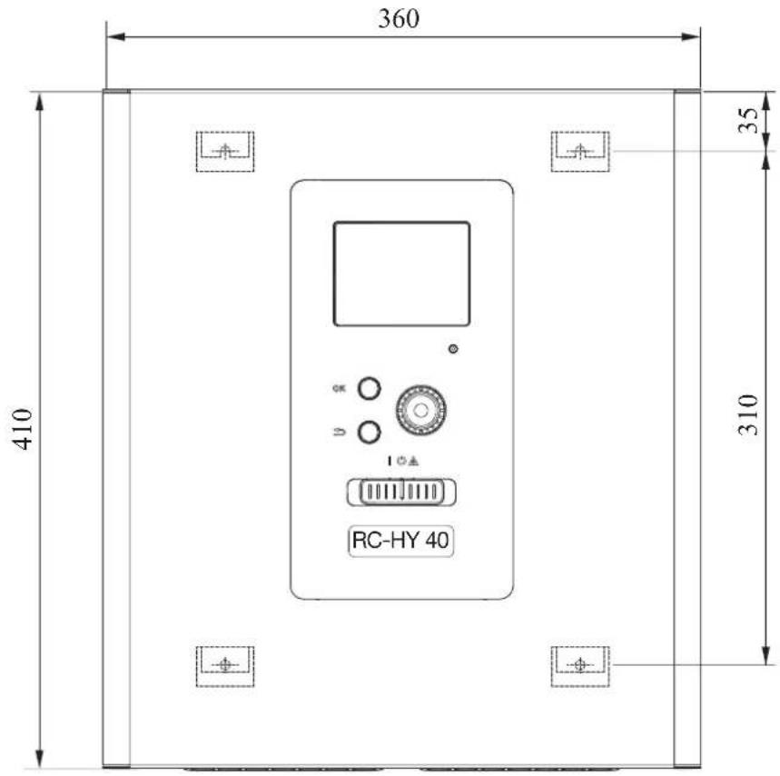

Electrical circuit diagram
HSB60
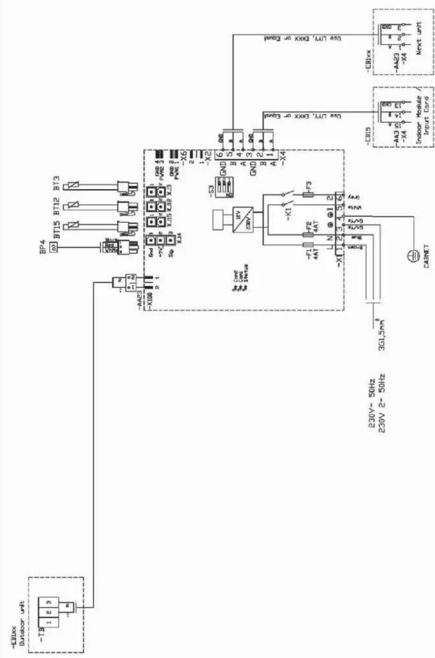
HMK60
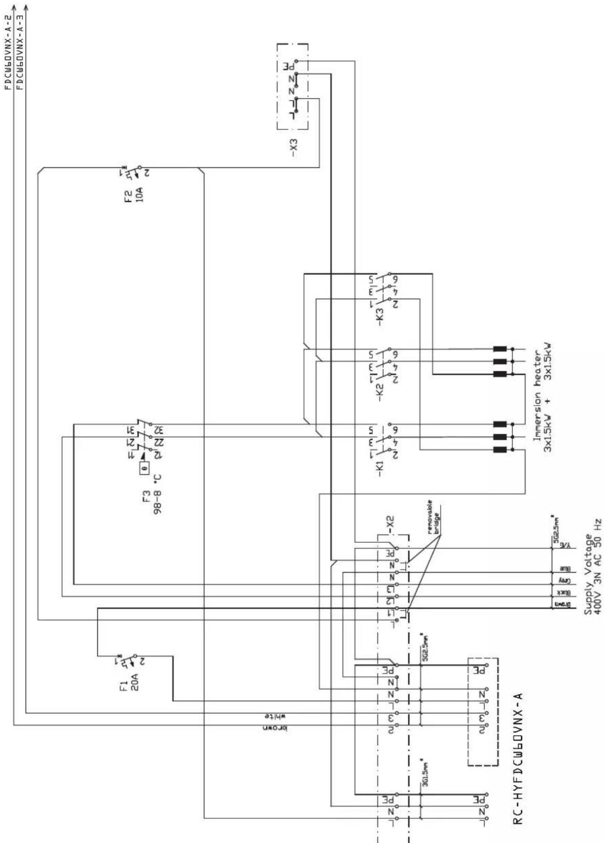
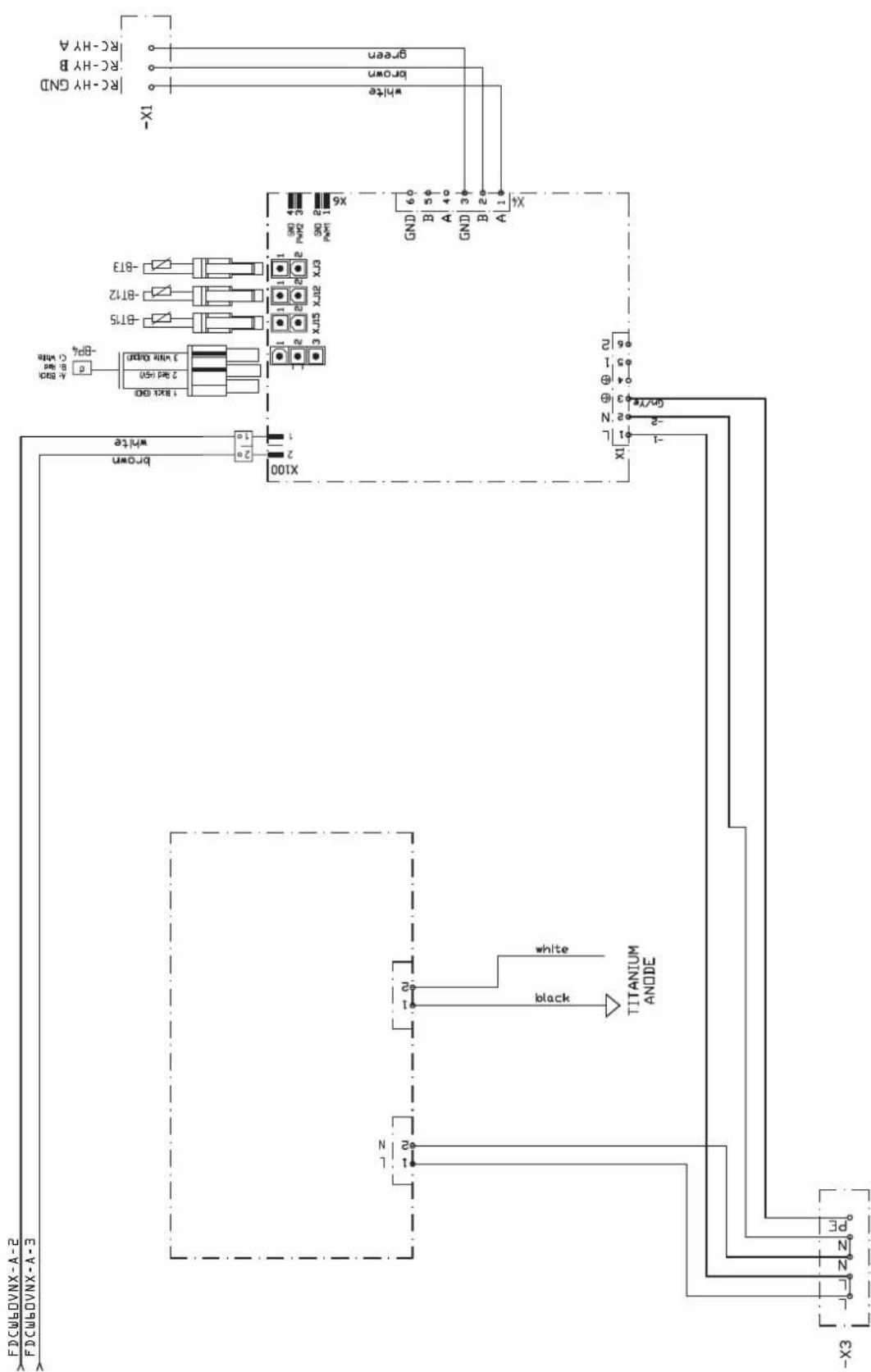
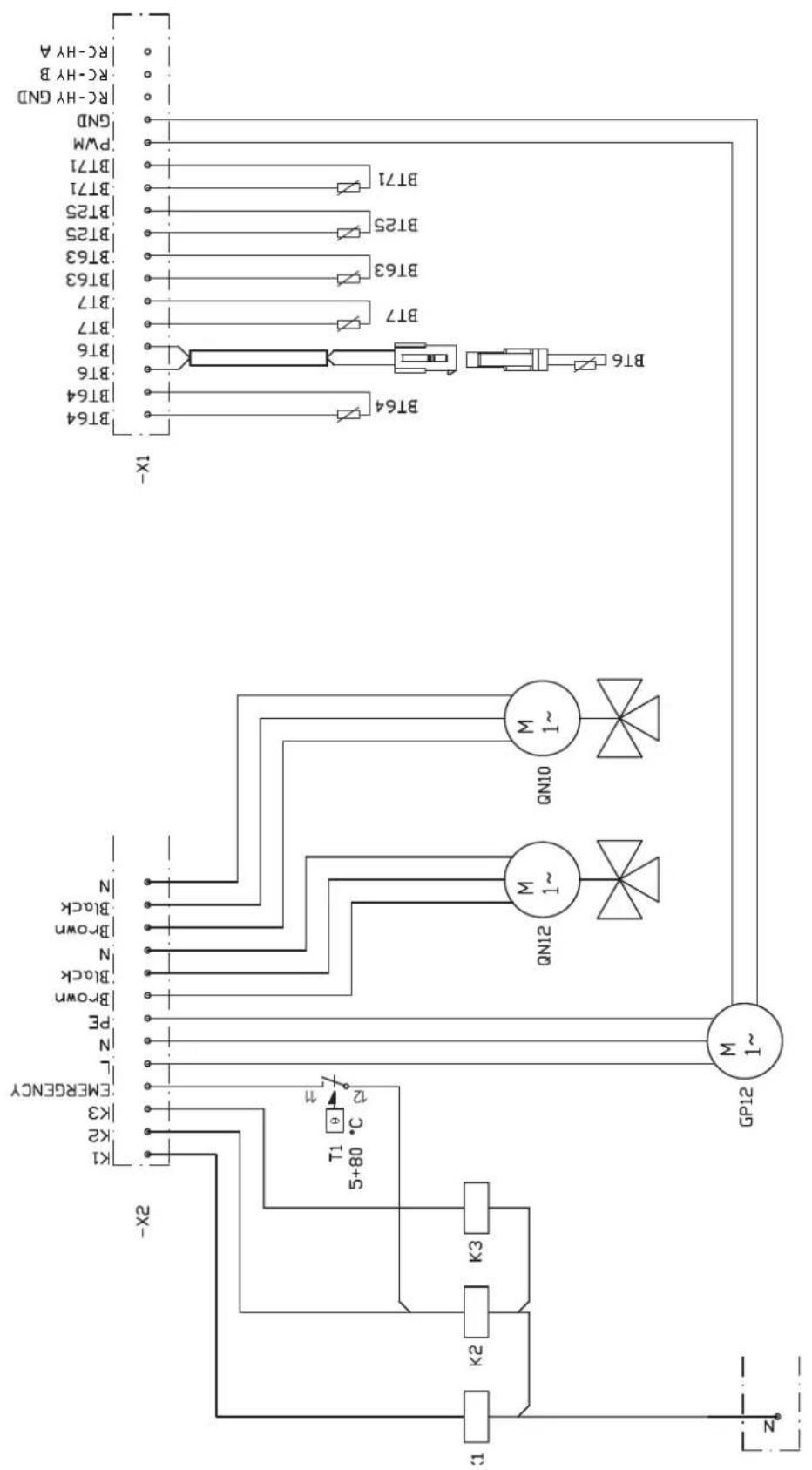
RC-HY20
sheet 1

sheet 2

sheet 3

sheet 4
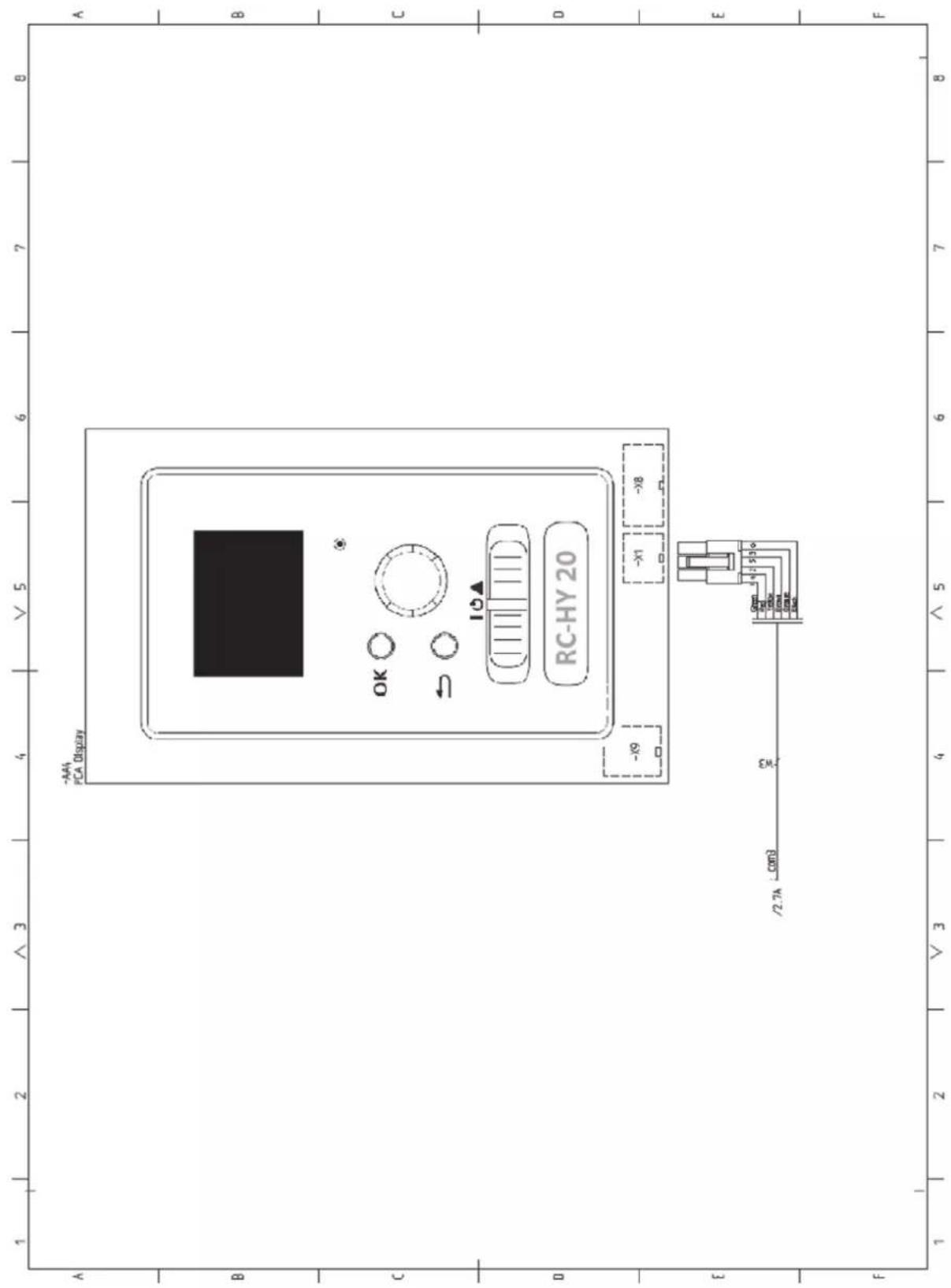
RC-HY40
sheet 1

sheet 2

sheet 3
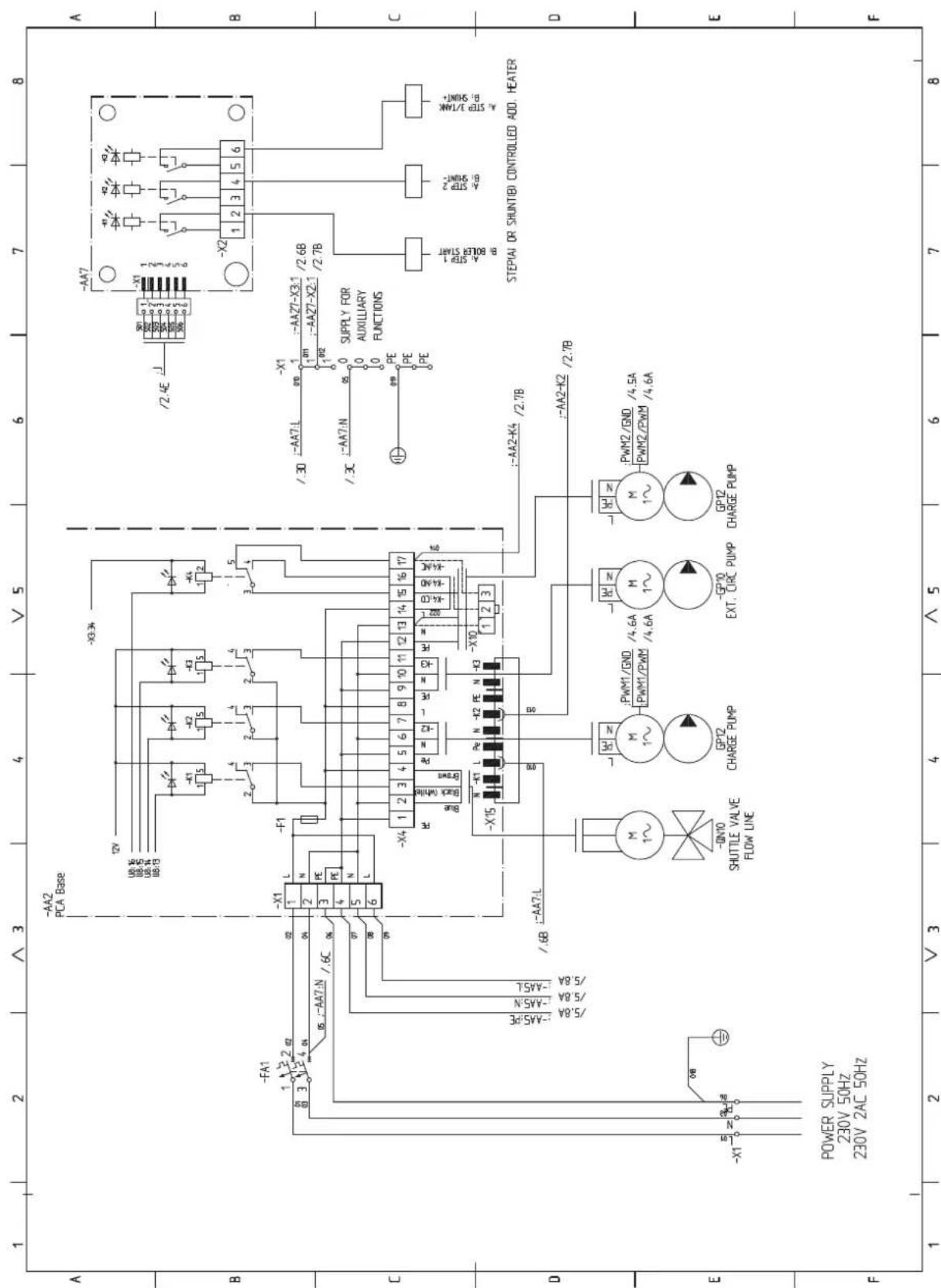
sheet 4

sheet 5

sheet 6
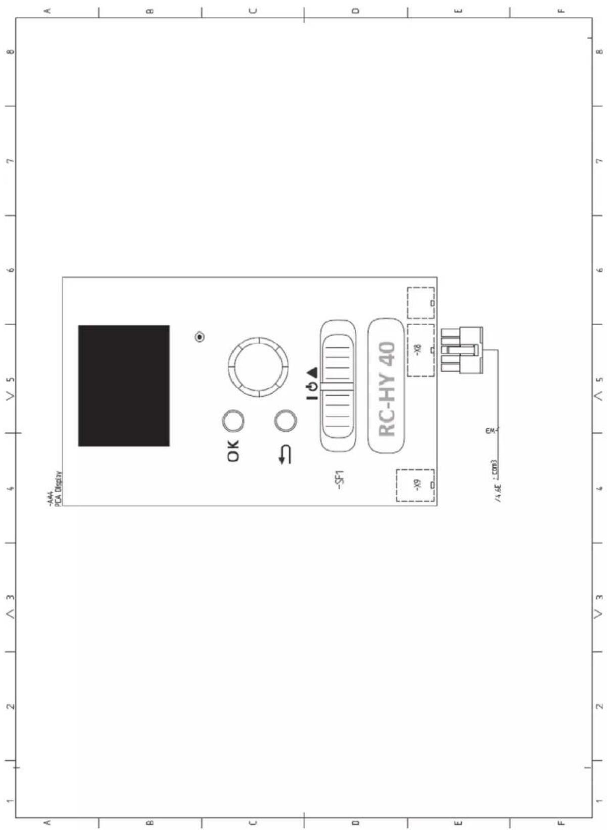

16-5 Konan 2-chome, Minato-ku, Tokyo, 108-8215, Japan
5 The Square, Stockley Park, Uxbridge, Middlesex, UB11 1ET, United Kingdom
Tel: +44-333-207-4072
Fax:+44-333-207-4089
http://www.mhiae.com
Air to Water Heat Pump
Hy drolution (HM)
HSB100/HMK100/FDCW71VNX/FDCW100VNX
PT300/PT500/RC-HY20/RC-HY40
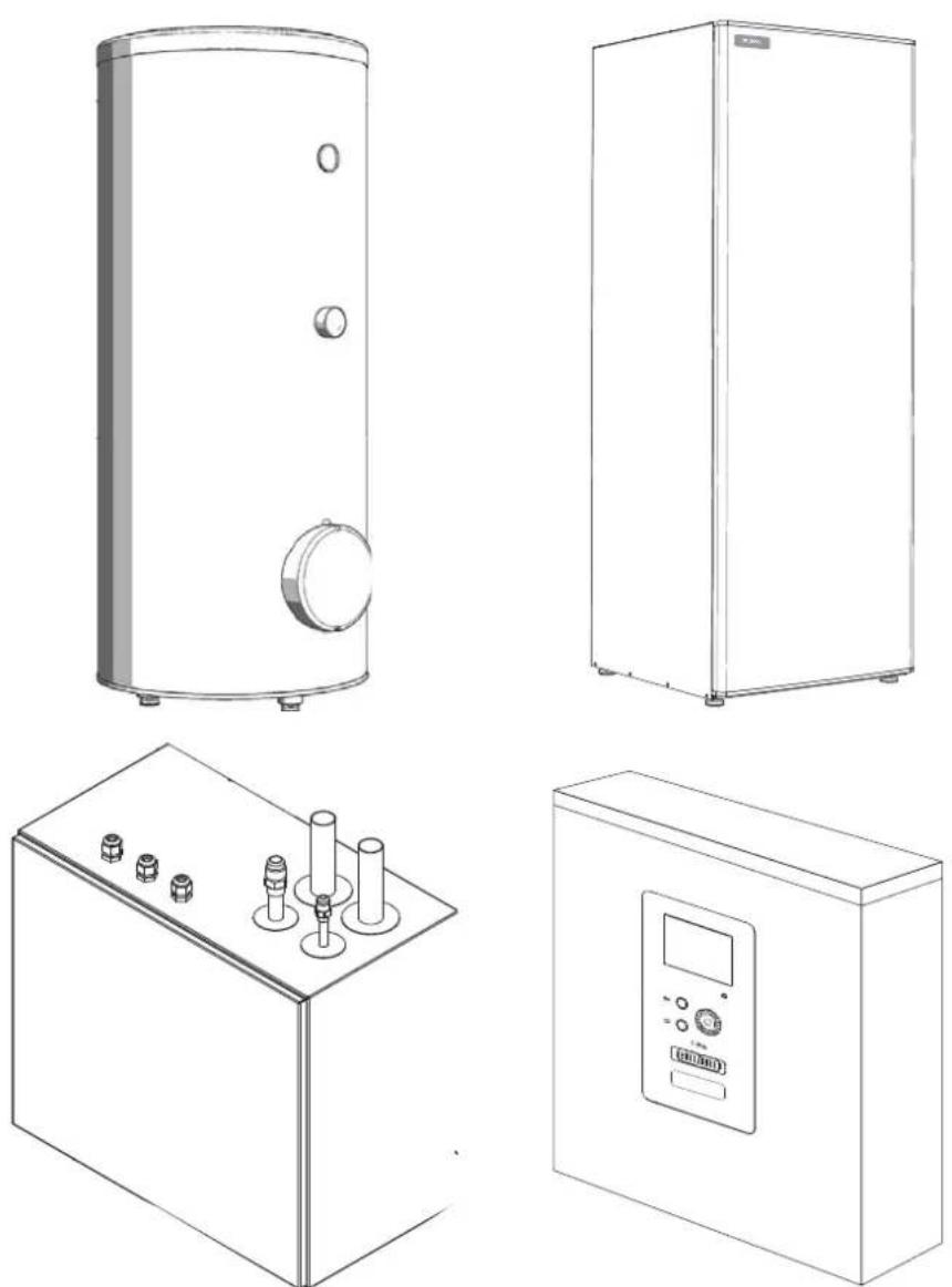
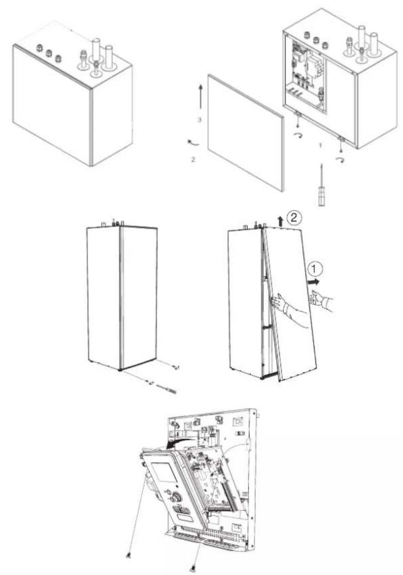
FDCW71VNX
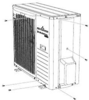
natural_image
Technical line drawing of a large industrial air conditioning unit with ventilation grilles and control panel (no text or labels)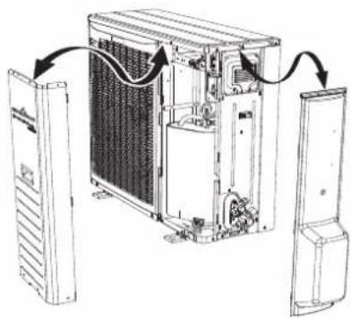
natural_image
Diagram of an internal air conditioning unit with cooling fans and ventilation ducts, showing no text or symbolsFDCW100VNX
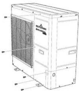
natural_image
Technical line drawing of a large industrial air conditioning unit with ventilation grilles and control panel (no text or labels)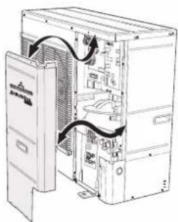
natural_image
Technical line drawing of an internal server rack with ventilation ducts and door panel (no text or labels)Safety precautions 2
General information for installer 7
Over view and design 7
Transport and storage 10
Supplied components 10
Assembly 10
Hanging indoor unit 12
Hanging control unit 12
Dimensioning expansion vessel 13
Recommended installation order 13
Pipe installation 14
General 14
Installation diagram 14
HSB100 14
HMK100 15
System requirements 16
Overflow valve 16
Pump capacity diagram 16
Pressure drop in indoor unit 17
Dimensions and pipe connections 17
HSB100 17
HMK100 17
PT300/500 18
Water circuit 19
Connection to heating system 19
Connection to hot water heater 19
Housing disassembly of tank unit 19
Connecting hot water tank to indoor unit 20
Connecting hot water tank to water main 21
Hot water circulation circuit 22
Connection of external heat source 23
Refrigerant circuit 23
Connecting refrigerant pipes 23
Piping insulation 23
Drain connection 23
Dockings 24
Electrical installation 29
General 29
Electrical components 30
Accessibility, electrical connection for controller 32
Cable lock 34
Connection 34
Power supply 34
Connection between indoor and outdoor unit 34
Connection between indoor unit and controller 35
Cascade connection setting 35
Recommended fuse size for HSB100 35
Recommended cable size for HSB1000 35
Circuit breaker 35
Power supply 35
Connection between indoor and outdoor unit 36
Connection between indoor unit and controller 36
Recommended fuse size for HMK100 36
Power supply 36
Connection between controller and indoor unit 37
HSB100 with RC-HY20 37
HSB100 with RC-HY40 37
HMK100 with RC-HY20 38
HMK100 with RC-HY40 38
Connection between controller and circulation pump (GP12) 38
HSB100 with RC-HY20 38
HSB100 with RC-HY40 39
HMK100 with RC-HY20 39
HMK100 with RC-HY40 40
Connection between controller and 3-way valve (QN10/QN12) 40
HSB100 with RC-HY20 40
HSB100 with RC-HY40 40
HMK100 with RC-HY20 41
HMK100 with RC-HY40 42
Connection between controller and sensors 42
RC-HY20 with HSB100 42
RC-HY20 with HMK100 43
RC-HY40 with HSB100 45
RC-HY40 with HMK100 46
Optional connections 48
RC-HY20 48
• Room sensor BT50 48
- Step controlled additional heat 49
Connection example with HMK100 49
- Relay output for emergency mode 50
Connection example with HMK100 50
- External circulation pump 51
- AUX inputs/outputs 51
- myUpway™ 53
RC-HY40 53
- Load monitor 53
- Room sensor BT50 54
- Step controlled additional heat 54
- Relay output for emergency mode 54
- External circulation pump 54
- AUX inputs/outputs 54
- myUpway™ 55
Commissioning and adjusting 56
Preparation 56
Filling and venting 56
Hot water tank 56
Climate system 56
Inspection of installation 56
Start-up and inspection 57
Before start-up 57
Commissioning with heat pump 57
Commissioning with additional heater only 57
3-way valve operation check 57
AUX function check 57
Cooling mode 57
Cleaning particle filter 57
Secondary adjustment 57
Start guide 58
Heating/cooling curve setting 59
Hot water circulation setting 60
SG ready 61
Control 62
Display unit 62
Menu system 63
Menu list 66
Menu 1 – Indoor climate 66
Menu 2 – Hot water 66
Menu 3 – Info 66
Menu 4 – My system 66
Menu 5 – Service 67
Service 75
Disturbances in comfort 78
Manage alarm 78
Troubleshooting 78
Additional heating only 79
Alarm list 80
Accessories 83
Technical data 84
Dimensions and setting-out coordinates 84
Electrical circuit diagram 85
Safety precautions
When installing the unit, be sure to check whether the selection of installation place, power supply specifications, usage limitation (piping length, height differences between indoor and outdoor units, power supply voltage and etc.) and installation spaces.
- We recommend you to read this "SAFETY PRECAUTIONS" carefully before installation in order to gain full advantage of the functions of the unit and to avoid malfunction due to mishandling.
- The precautions described below are divided into ⚠WARNING and ⚠CAUTION. The matters with possibilities leading to serious consequences such as death or serious personal injury due to erroneous handling are listed in the ⚠WARNING and the matters with possibilities leading to personal injury or damage of the unit due to erroneous handling including probability leading to serious consequences in some cases are listed in ⚠CAUTION. These are very important precautions for safety. Be sure to observe all of them without fail.
- Be sure to confirm no anomaly on the equipment by commissioning after completed installation and explain the operating methods as well as the maintenance methods of this equipment to the user according to the owner's manual.
- Keep the installation manual together with owner's manual at a place where any user can read at any time. Moreover if necessary, ask to hand them to a new user.
This heat pump complies with EMC Directive 2014/30/EU.
This appliance is designed for use in a home environment and can be used by children aged from 8 years and above and persons with reduced physical, sensory or mental capabilities or lack of experience and knowledge if they have been given supervision or instruction concerning use of the appliance in a safe way and understand the hazards involved. Children
shall not play with the appliance. Cleaning and user maintenance shall not be made by children without supervision.
This in accordance to applicable parts of the low voltage directive 2014/35/EU, LVD.
This appliance is also intended for use by experts or trained users in shops, hotels, light industry, on farms and in similar environments.
CE marking is applicable to the area of 50 Hz power supply.
The emission sound pressure level from each Indoor and Outdoor unit is under 70 dB(A).
WARNING
Installation must be carried out by the qualified installer.

If you install the system by yourself, it may cause serious trouble such as water leaks, electric shocks, fire and personal injury, as a result of a system malfunction.
Install the system in full accordance with the instruction manual.

Incorrect installation may cause bursts, personal injury, water leaks, electric shocks and fire.
Use the original accessories and the specified components for installation.

If parts other than those prescribed by us are used, It may cause water leaks, electric shocks, fire and personal injury.
When installing in small rooms, take prevention measures not to exceed the density limit of refrigerant in the event of leakage.

Consult the expert about prevention measures. If the density of refrigerant exceeds the limit in the event of leakage, lack of oxygen can occur, which can cause serious accidents.
Ventilate the working area well in the event of refrigerant leakage during installation.

If the refrigerant comes into contact with naked flames, poisonous gas is produced.
After completed installation, check that no refrigerant leaks from the system.

If refrigerant leaks into the room and comes into contact with an oven or other hot surface, poisonous gas is produced.
Hang up the unit at the specified points with ropes which can support the weight in lifting for portage. And to avoid jolting out of alignment, be sure to hang up the unit at 4-point support.
An improper manner of portage such as 3-point support can cause death or serious personal injury due to falling of the unit.
Install the unit in a location with good support.
Unsuitable installation locations can cause the unit to fall and cause material damage and personal injury.
Ensure the unit is stable when installed, so that it can withstand earthquakes and strong winds.
Unsuitable installation locations can cause the unit to fall and cause material damage and personal injury.
Ensure that no air enters in the refrigerant circuit when the unit is installed and removed.
If air enters in the refrigerant circuit, the pressure in the refrigerant circuit becomes too high, which can cause burst and personal injury.
The electrical installation must be carried out by the qualified electrician in accordance with “the norm for electrical work” and “national wiring regulation”, and the system must be connected to the dedicated circuit.
Power supply with insufficient capacity and incorrect function done by improper work can cause electric shocks and fire.
Be sure to shut off the power before starting electrical work.
Failure to shut off the power can cause electric shocks, unit failure or incorrect function of equipment.
Be sure to use the cables conformed to safety standard and cable ampacity for power distribution work.
Unconformable cables can cause electric leak, anomalous heat production or fire.
Use the prescribed cables for electrical connection, tighten the cables securely in terminal block and relieve the cables correctly to prevent overloading the terminal blocks.
Loose connections or cable mountings can cause anomalous heat production or fi re.
Arrange the wiring in the control box so that it cannot be pushed up further into
the box. Install the service panel correctly.
Incorrect installation may result in overheating and fire.
Do not perform brazing work in the airtight room.
It can cause lack of oxygen.
Use the prescribed pipes, flare nuts and tools for R410A.
Using existing parts (for R22 or R407C) can cause the unit failure and serious accidents due to burst of the refrigerant circuit.
Tighten the flare nut by using double spanners and torque wrench according to prescribed method. Be sure not to tighten the flare nut too much.
Loose fl are connection or damage on the fl are part by tightening with excess torque can cause burst or refrigerant leaks which may result in lack of oxygen.
Do not open the service valves for liquid line and gas line until completed refrigerant piping work, air tightness test and evacuation.
If the compressor is operated in state of opening service valves before completed connection of refrigerant piping work, air can be sucked into refrigerant circuit, which can cause bust or personal injury due to anomalously high pressure in the refrigerant.
Do not put the drainage pipe directly into drainage channels where poisonous gases such as sulphide gas can occur.
Poisonous gases will flow into the room through drainage pipe and seriously affect the user's health and safety.
Only use prescribed optional parts. The installation must be carried out by the qualified installer.
If you install the system by yourself, it can cause serious trouble such as water leaks, electric shocks, fire.
Do not run the unit with removed panels or protections
Touching rotating equipments, hot surfaces or high voltage parts can cause personal injury due to entrapment, burn or electric shocks.
Be sure to fix up the service panels.
Incorrect fi xing can cause electric shocks or fi re due to intrusion of dust or water.
Do not perform any repairs or modifications by yourself. Consult the dealer if the unit requires repair.
If you repair or modify the unit, it can cause water
leaks, electric shocks or fire.
Do not perform any change of protective device itself or its setup condition

The forced operation by short-circuiting protective device of pressure switch and temperature controller or the use of non specified component can cause fire or burst.
Be sure to switch off the power supply in the event of installation, inspection or servicing.

If the power supply is not shut off, there is a risk of electric shocks, unit failure or personal injury due to the unexpected start of fan.
Consult the dealer or an expert regarding removal of the unit.

Incorrect installation can cause water leaks, electric shocks or fire.
Stop the compressor before disconnecting refrigerant pipes in case of pump down operation.

If disconnecting refrigerant pipes in state of opening service valves before compressor stopping, air can be sucked, which can cause burst or personal injury due to anomalously high pressure in the refrigerant circuit.

CAUTION
Carry out the electrical work for ground lead with care.

Do not connect the ground lead to the gas line, water line, lightning conductor or telephone line's ground lead. Incorrect grounding can cause unit faults such as electric shocks due to short-circuiting.
Use the circuit breaker with sufficient breaking capacity.

If the breaker does not have sufficient breaking capacity, it can cause the unit malfunction and fi re.
Earth leakage breaker must be installed.

If the earth leakage breaker is not installed, it can cause electric shocks.
Do not use any materials other than a fuse with the correct rating in the location where fuses are to be used.

Connecting the circuit with copper wire or other metal thread can cause unit failure and fi re.
Do not install the unit near the location where leakage of combustible gases can occur.

If leaked gases accumulate around the unit, it can
cause fi re.
Do not install the unit where corrosive gas (such as sulfurous acid gas etc.) or combustible gas (such as thinner and petroleum gases) can accumulate or collect, or where volatile combustible substances are handled.

Corrosive gas can cause corrosion of heat exchanger, breakage of plastic parts and etc. And combustible gas can cause fi re.
Secure a space for installation, inspection and maintenance specified in the manual.

Insufficient space can result in accident such as personal injury due to falling from the installation place.
When the outdoor unit is installed on a roof or a high place, provide permanent ladders and handrails along the access route and fences and handrails around the outdoor unit.

If safety facilities are not provided, it can cause personal injury due to falling from the installation place.
Do not use the indoor unit at the place where water splashes may occur.

Since the indoor unit is not waterproof, it can cause electric shocks and fi re.
Do not install or use the system close to the equipment that generates electromagnetic fields or high frequency harmonics.

Equipment such as inverters, standby generators, medical high frequency equipments and telecommunication equipments can affect the system, and cause malfunctions and breakdowns. The system can also affect medical equipment and telecommunication equipment, and obstruct its function or cause jamming.
Do not install the outdoor unit in a location where insects and small animals can inhabit.

Insects and small animals can enter the electric parts and cause damage or fire. Instruct the user to keep the surroundings clean.
Do not use the base flame for outdoor unit which is corroded or damaged due to long periods of operation.

Using an old and damage base flame can cause the unit falling down and cause personal injury.
Do not install the unit in the locations listed below.

- Locations where carbon fi ber, metal powder or
any powder is floating.
- Locations where any substances that can affect the unit such as sulphide gas, chloride gas, acid and alkaline can occur.
- Vehicles and ships.
- Locations where cosmetic or special sprays are often used.
- Locations with direct exposure of oil mist and steam such as kitchen and machine plant.
- Locations where any machines which generate high frequency harmonics are used.
- Locations with salty atmospheres such as coastlines.
- Locations with heavy snow (If installed, be sure to provide base flame and snow hood mentioned in the manual).
- Locations where the unit is exposed to chimney smoke.
- Locations at high altitude (more than 1000m high).
- Locations with ammonic atmospheres.
- Locations where heat radiation from other heat source can affect the unit.
- Locations without good air circulation.
- Locations with any obstacles which can prevent inlet and outlet air of the unit.
- Locations where short circuit of air can occur (in case of multiple units installation).
- Locations where strong air blows against the air outlet of outdoor unit.
It can cause remarkable decrease in performance, corrosion and damage of components, malfunction and fire.
Do not install the outdoor unit in the locations listed below.

- Locations where discharged hot air or operating sound of the outdoor unit can bother neighborhood.
- Locations where outlet air of the outdoor unit blows directly to plants.
- Locations where vibration can be amplified and transmitted due to insufficient strength of structure.
- Locations where vibration and operation sound generated by the outdoor unit can affect seriously. (on the wall or at the place near bed room)
- Locations where an equipment aff ected by high harmonics is placed. (TV set or radio receiver is placed within 5m)
- Locations where drainage cannot run off safely. It can affect surrounding environment and cause a claim.
Do not install the remote controller at the direct sunlight.

It can cause malfunction or deformation of the remote controller.
Do not use the unit for special purposes such as storing foods, cooling precision instruments and preservation of animals, plants or art.

It can cause the damage of the items.
Take care when carrying the unit by hand.

If the unit weights more than 20kg, it must be carried by two or more persons. Do not carry by the plastic straps, always use the carry handle when carrying the unit by hand. Use gloves to minimize the risk of cuts by the aluminum fins.
Dispose of any packing materials correctly.

Any remaining packing materials can cause personal injury as it contains nails and wood. And to avoid danger of suffocation, be sure to keep the plastic wrapper away from children and to dispose after tear it up.
Pay attention not to damage the drain pan by weld spatter when welding work is done near the indoor unit.

If weld spatter entered into the indoor unit during welding work, it can cause pin-hole in drain pan and result in water leakage. To prevent such damage, keep the indoor unit in its packing or cover it.
Be sure to insulate the refrigerant pipes so as not to condense the ambient air moisture on them.

Insufficient insulation can cause condensation, which can lead to moisture damage on the ceiling, floor, furniture and any other valuables.
Be sure to perform air tightness test by pressurizing with nitrogen gas after completed refrigerant piping work.

If the density of refrigerant exceeds the limit in the event of refrigerant leakage in the small room, lack of oxygen can occur, which can cause serious accidents.
Do not touch any buttons with wet hands.

It can cause electric shocks.
Do not shut off the power supply immediately after stopping the operation.

Wait at least 5 minutes, otherwise there is a risk of water leakage or breakdown.
Do not control the system with main power switch.

It can cause fire or water leakage. In addition, the
fan can start unexpectedly, which can cause personal injury.
Do not touch any refrigerant pipes when the system is in operation.
During operation the refrigerant pipes become extremely hot or extremely cold depending the operating condition, and it can cause burn injury or frost injury.
This manual is only for outdoor units connected to HSB series and HMK series.
When you connect other indoor units to outdoor units, please refer to other manual.
Notabilia for units designed for R410A
Only use R410A refrigerant. R410A is the refrigerant whose pressure is 1.6 times as high as that of conventional refrigerant.
The size of charging port of service valve and check joint for R410A are altered from that for conventional refrigerant in order to prevent the system being charged with the incorrect refrigerant by mistake. And the protruding dimension of pipe for flare processing and flare nut size for R410A are also altered from that for conventional refrigerant in order to reinforce strength against the pressure for R410A. Accordingly the dedicated tools for R410A listed in the below mentioned table should be prepared for installation and servicing.
| Dedicated tools for R410A | |
| a) | Gauge manifold |
| b) | Charge hose |
| c) | Electronic scale for refrigerant charge |
| d) | Torque wrench |
| e) | Flare tool |
| f) | Protrusion control gauge for copper pipe |
| g) | Vacuum pump adapter |
| h) | Gas leak detector |
Do not use charging cylinder. Using charging cylinder may alter the composition of refrigerant, which results in making the performance of the system worse.
Refrigerant must be charged always in liquid state from the bottle.
General information for installer
For outdoor unit installation information, see Installation manual for Outdoor unit.
Over view and design
HSB100

Pipe connections
XL1(Red mark) Climate system supply
XL2 (Blue mark) Climate system return
XL14 Connection, gas line
XL13 Connection, liquid line
Valves etc.
EP2 Heat exchanger
HQ1 Particle filter (supplied)
HZ2 Drying filter
Sensor, thermostats
BP4 Pressure sensor, high pressure
BT3 Temperature sensor, heating medium, return
BT12 Temperature sensor, condenser, supply
BT15 Temperature sensor, fluid pipe
Miscellaneous
UB1 Cable gland
UB2 Cable gland
UB3 Cable gland
Electrical components
AA23 Communication board
AA23-F3 Fuse for external heating cable
AA23-S3 DIP switch, addressing of outdoor unit
AA23-X1 Terminal block, incoming supply, connection of KVR
AA23-X4 Terminal block, communication with indoor module / control module
AA23-X100 Terminal block, communication outdoor module
HMK100

Pipe connections
XL1(→) Connection, heating medium, supply
XL2(→) Connection, heating medium, return
XL3 Connection, cold water
XL4 Connection, hot water
XL10 Connection, cooling
XL11 Connection, safety group, manometer
XL13 Connection, liquid cooling medium
XL14 Connection, gas cooling medium
HVAC elements
CM1 Diaphragm expansion vessel, closed
QN10 Isolation valve, domestic hot water/central heating
QN12 Isolation valve, cooling/heating
GP12 Circulation pump
EP2 Heat exchanger
Sensors
BP4 Pressure sensor, high pressure
BT3 Temperature sensor, heating medium return
BT6 Temperature sensor, hot water loading
BT7 Temperature sensor, top of the hot water heater
BT12 Temperature sensor, condenser outlet
BT15 Temperature sensor, liquid
BT25 Temperature sensor, heating medium supply
BT63 Temperature sensor, heating medium supply downstream the submersible heater
BT64 Temperature sensor, cooling medium supply
BT71 Temperature sensor, heating medium re-turn
Others
EB15 HMK 100
PF3 Serial number
EB2 Domestic hot water tank
PT300/500
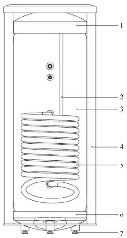

Section of the PT storage tanks.
- Upper insulation of the storage tank
- Protective magnesium anode
- Enamelled tank
- Side insulation of the storage tank
- Coil
- Lower insulation of the storage tank
- Adjustable foot
Side view of the PT storage tanks.
- Thermometer
- Connector pipe for mounting electric heating unit
- Inspection opening
- Hot water intake connector pipe
- Hot water circulation connector pipe
- Temperature sensor cover
- Coil supply connector pipe
- Connection of return line from the coil
- Cold water supply connector pipe
Transport and storage
Indoor unit and tank unit must be transported and stored vertically in dry conditions.
Supplied components
HSB100 Indoor unit
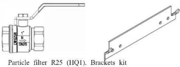
HMK100 Indoor unit with tank
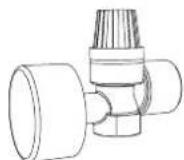
Safety valve with pressure gauge
RC-HY20/40 Control unit
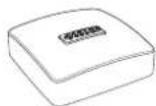
Outside sensor
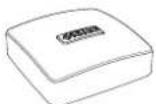
Room sensor (RC-HY40 only)

Insulation tape
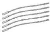
Temperature sensor
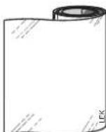
Aluminium tape

Cable ties
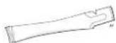
Heating pipe paste

Current sensor (RC-HY40 only)
Assembly
It is recommended that indoor unit is installed in a room with existing floor drainage, most suitably in a utility room or boiler room.
■ For indoor unit and control unit, the mounting surface must be fl rm, fl at and vertical, preferably a concrete wall.
■ Indoor unit with tank and tank unit must be set on a solid waterproof base that would keep the weight of the unit. The height-adjusting legs allow for levelling and stable setting.
HMK100

PT300/500
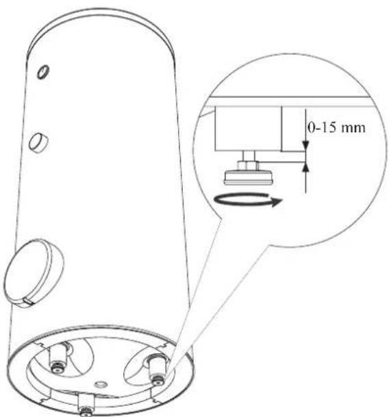
■ For indoor unit with tank, floor drain port is required to connect drain hose in case cooling function is used.
■ Install indoor unit with its back to an outside wall, ideally in a room where noise does not matter. If this is not possible, avoid placing it against a wall behind a bedroom or other room where noise may be a problem.
■ Route pipes so they are not fixed to an internal wall that backs on to a bedroom or living room.
■ Install indoor unit with tank, tank unit and its pipings to indoor unit indoors in order to avoid icing.
■ Ensure free space described in the following figures for future maintenance.
HSB100
Recommendation for positioning on wall

Recommendation for positioning in corner

*Min 800mm is required in front
HMK100
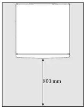
IMPORTANT
For HMK100, leave 10 – 25 mm free space between the indoor module and the back wall for cables and piping.
PT300/500
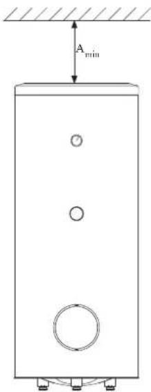
A _min is required on top to replace anode bar, and 500 mm is required in front to replace immersion heater if equipped.
| Application | Connector pipe dia. | Type of anode A | min |
| PT300 | 1" Chain 26 × 8 | 150 mm | |
| 34 " Titanium anode 200 mm | |||
| PT500 | 114 " Chain 33 × 5 | 150 mm | |
| 34 " Titanium anode 400 mm | |||
RC-HY20/40
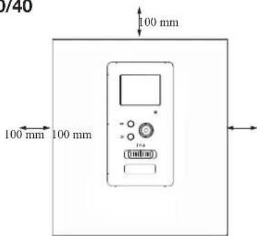
Hanging indoor unit
It is recommended that the split box is installed in a room with existing floor drainage, most suitably in a utility room or boiler room.
- The bracket for the split box is mounted to the wall by use of appropriate screws.

- Insert HSB100 in the bracket mounted to the wall.

natural_image
Technical line drawing of a mechanical enclosure with multiple cylindrical components and mounting brackets (no text or symbols)NOTE
Indoor unit weigh 18 kg excluding water inside.
Hanging control unit
Use all mounting points and install control unit upright against a fl at wall. Make sure whole back surface faces the wall.
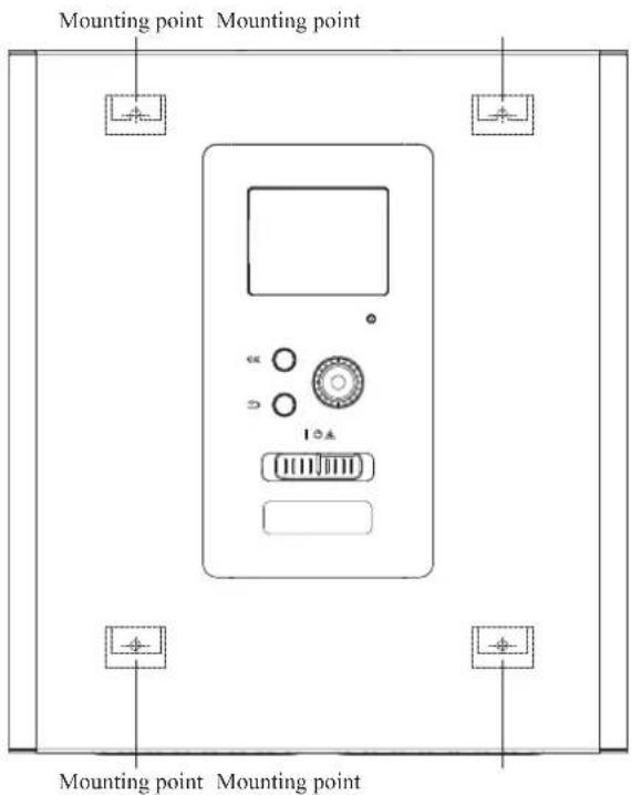
Dimensioning expansion vessel
The expansion vessel volume must be at least 5% of total water volume in the circulation system.
HMK100 is equipped with an expansion vessel with a volume of 10 liters.
Initial pressure and max height difference
Recommended maximum height difference between expansion vessel and the highest point in the system is 5m.
The initial pressure of the pressure expansion vessel must be dimensioned according to the maximum height (H) between the vessel and the highest positioned radiator, see figure. An initial pressure of 0.5 bar (5 mvp) means a maximum permitted height difference of 5 m.
If the standard initial pressure in the pressure vessel is not high enough it can be increased by filling via the valve in the expansion vessel. The expansion vessel's standard initial pressure must be entered in the check list on User's manual.
Any change in the initial pressure affects the ability of the expansion vessel to handle the expansion of the water.
Consult local distributor in case height difference exceeds 5m.

Recommended installation order
- Hang indoor unit and control unit to appropriate position and connect indoor unit and tank unit.
- Connect indoor unit to climate system, cold and hot water lines as well as any external heat sources. See page 14, 15. Also see docking descriptions on page 26-28 and further on.
- Install refrigerant pipes according to the description on the Installation manual for outdoor unit.
- Connect current limiter, any centralised load control and external contacts as well as the cable between indoor unit and outdoor unit.
- Connect incoming electricity to indoor unit and/or outdoor unit. See page 34-36.
- Follow the commissioning instructions on page 37-55.
Pipe installation
General
Pipe installation must be carried out in accordance with current norms and directives.
A following table shows plumbing necessary for each product.
| Refrigerant Plumbing | ||
| HSB Necessary Necessary | ||
| HMK Necessary Necessary | ||
| PT — Necessary | ||
| PC-HY — — | ||
This heat pump system is designed for low or medium temperature heating system. It is recommended water temperature must not exceed 55^ on supply and 45^ on
return at lowest design outdoor temperature (DOT) though indoor unit can operate with a return temperature of up to 65°C and an outgoing temperature from the unit of 65°C.
Indoor unit is not equipped with shut off valves; these must be installed outside the heat pump to facilitate any future servicing.
Indoor unit can be connected to the radiator system, floor heating system and/or fan convectors.
Safety valve is not equipped with in indoor unit. Make sure to install safety valve in the circuit.
Installation diagram
FDCW71/100VNX outdoor unit provides heat for space heating and domestic hot water using free energy in the outdoor air within the range of low temperature up to -20°C. Connection is different according to the type of indoor unit (see below figures). The system is controlled by RC-HY20 or RC-HY40 control unit.
HSB100
HSB100 indoor unit is equipped with plate heat exchanger. It needs to install expansion vessel, shut-off valves, safety valve, electric heater and circulation pump to make a complete heating system. In case domestic hot water is required, 3 way valve and tank is also necessary.
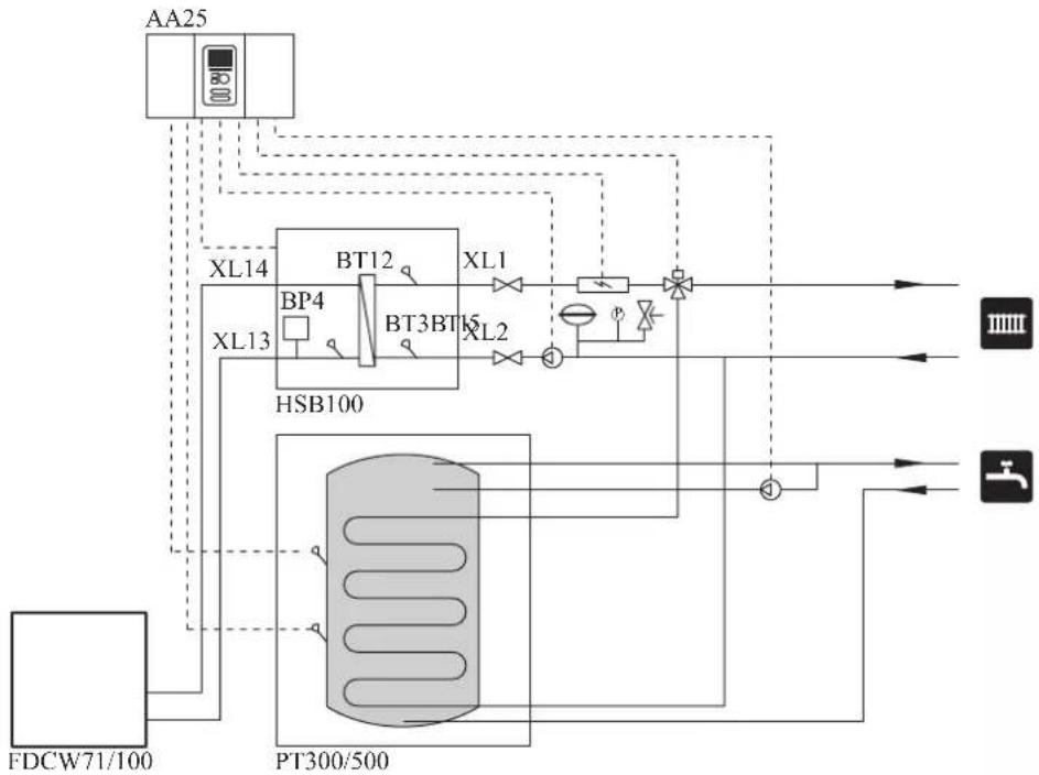
flowchart
graph TD
    A["AA25"] --> B["XL14"]
    A --> C["XL13"]
    B --> D["BT12"]
    C --> E["BT3BT6"]
    D --> F["XL1"]
    E --> G["XL2"]
    F --> H["PT300/500"]
    G --> H
    H --> I["IIIII"]
    H --> J["J"]
    K["FDCW71/100"] --> L["PT300/500"]
    style A fill:#f9f,stroke:#333
    style K fill:#ccf,stroke:#333
HMK100
HMK100 indoor unit is equipped with coil water heater, expansion vessel, safety valve, electric heater, plate heat exchanger, sensors and gauge, and circulation pump.
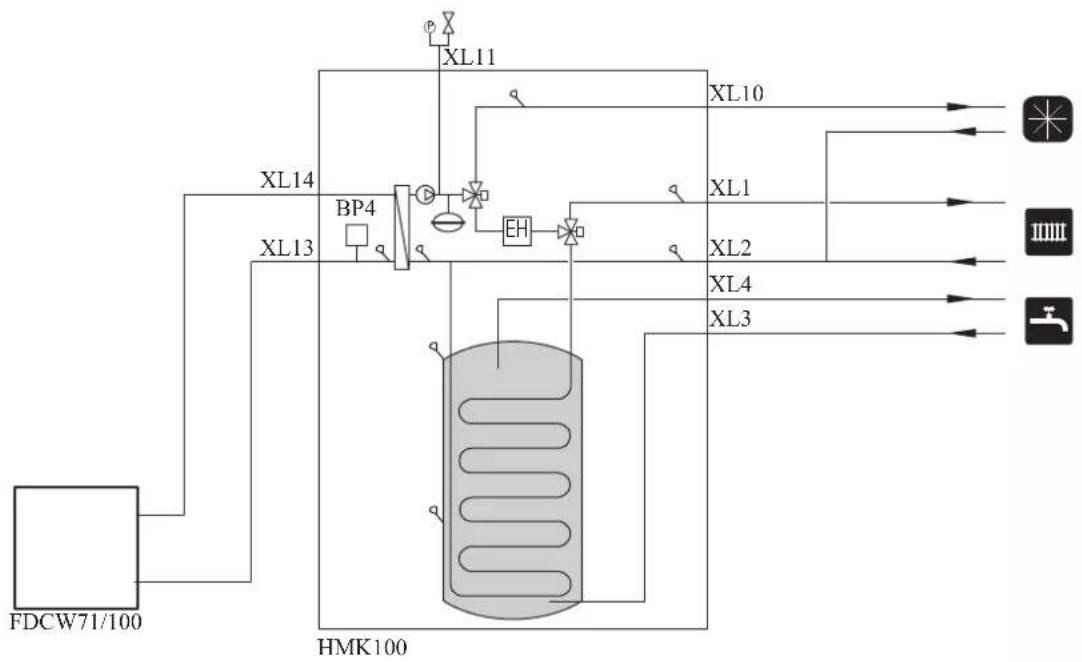
flowchart
graph TD
    A["FDCW71/100"] --> B["XL14"]
    A --> C["XL13"]
    B --> D["BP4"]
    C --> D
    D --> E["EH"]
    E --> F["XL10"]
    E --> G["XL1"]
    E --> H["XL2"]
    E --> I["XL4"]
    E --> J["XL3"]
    F --> K["Output 1"]
    G --> L["Output 2"]
    H --> M["Output 3"]
    I --> N["Output 4"]
    J --> O["Output 5"]
| Symbol | Meaning Symbol Meaning | ||
| ↑ | Vent | P | Manometer |
| ☒ | Cut-off valve Circulation pump ☑ | ||
| + | Water tap Particulate filter | ☐ | |
| ☒ | Non-return valve Compressor | ∅ | |
| ☒ | Balancing valve Heat exchanger | / | |
| ☒ | Three-way valve Cooling |  | |
| ☒ | Safety valve Central heating sy  | ||
| T | Thermometer Domestic hot wa |  | |
| q | Temperature sensor |  | Heating systems Floor heating |
| ∅ | Diaphragm expansion vessel |  | Cooling system |
System requirements
The minimum water volume in the climate system is subject to the values in the table below. If it is not fulfilled, volume vessel must be installed.
For more options, see the docking description on Page 24. (liter)
| With underf loor cooling application | Without underf loor cooling application | |
| HSB100, HMK100, FDCW71VNX | 80 50 | |
| HSB100, HMK100, FDCW100VNX | 100 80 |
Overflow valve
NOTE
A free flow is required for all docking options, which means that an overflow valve must be installed. The circulation pump may become damaged.
Pump capacity diagram
HSB100
HSB100 is not equipped with circulation pump.
This graph shows the characteristic of CPD11-25M/65 or 75.
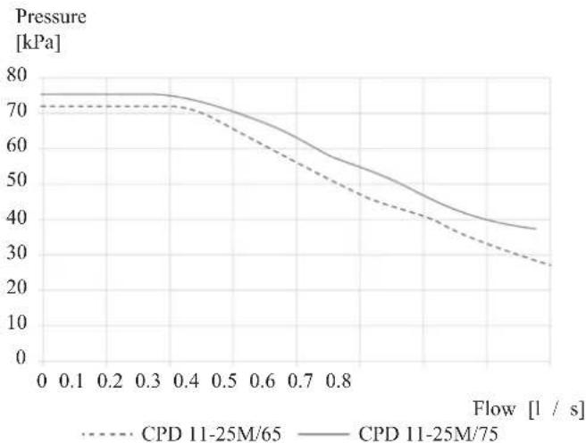
HMK100
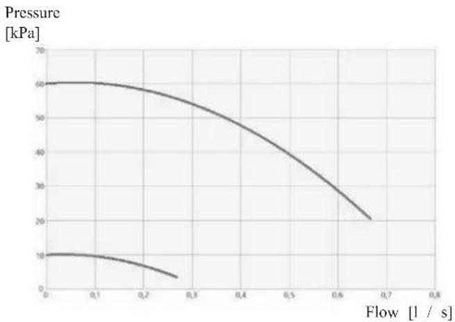
line
| Flow [l / s] | Pressure [kPa] | | ------------ | -------------- | | 0.0 | 60 | | 0.1 | 58 | | 0.2 | 52 | | 0.3 | 45 | | 0.4 | 38 | | 0.5 | 30 | | 0.6 | 22 | | 0.7 | 18 | | 0.8 | 15 |Pressure drop in indoor unit
HSB100
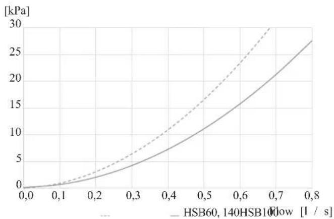
line
| Flow Rate [1 / s] | HSB60,140HSB10Flow [kPa] | | ----------------- | ------------------------ | | 0.0 | 0.0 | | 0.1 | 1.0 | | 0.2 | 3.0 | | 0.3 | 6.0 | | 0.4 | 10.0 | | 0.5 | 15.0 | | 0.6 | 20.0 | | 0.7 | 25.0 | | 0.8 | 28.0 |HMK100
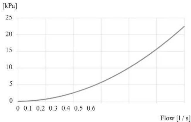
line
| Flow [l/s] | Pressure [kPa] | | ---------- | -------------- | | 0.0 | 0.0 | | 0.1 | 0.5 | | 0.2 | 1.5 | | 0.3 | 3.0 | | 0.4 | 5.0 | | 0.5 | 7.5 | | 0.6 | 10.0 | | 0.7 | 13.0 | | 0.8 | 16.0 | | 0.9 | 19.0 | | 1.0 | 22.0 |Connection of extra circulation pump
When connecting extra circulation pumps, requirements for pressure, maximum flow etc must be met. See page 27 for location.
NOTE
Non-return valve must be installed in case extra circulation pump is used. See page 27 for the position. The circulation pump may become damaged.
Dimensions and pipe connections HSB100
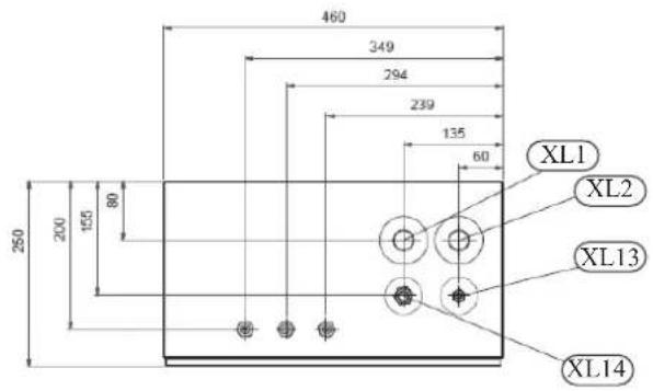
Pipe connections
| XL1 (Red mark) | Climate system, fl ow ø28 mm |
| XL2 (Blue mark) | Climate system, return ø28 mm |
| XL14 | Gas line refrigerant, fl are 58 " |
| XL13 | Liquid line refrigerant, fl are 38 " |
HMK100
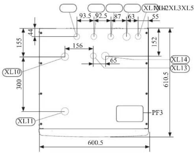
Pipe connections
| XL1(→) | Connection, Heating medium supply 22 mm |
| XL2(→) | Connection, Heating medium return 22 mm |
| XL3 | Connection, cold water 22 mm |
| XL4 | Connection, hot water 22 mm |
| XL5 | Connection, circulation 15 mm |
| XL13 | Connection, liquid cooling medium 38 " |
| XL14 | Connection, gas cooling medium 58 " |
| XL10 | Connection, cooling 22 mm |
| XL11 | Connection, safety valve 22 mm, manometer |
Other information
PF3 Serial number plate
PT300/500
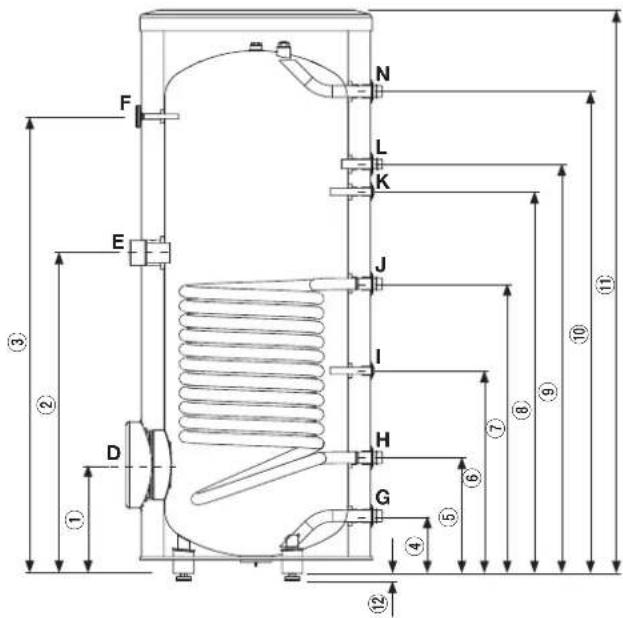
| Connection | U/m | PT300/500 | |
| D | Inspection opening mm 120 | ||
| E | Heating unit connection inch | 112 "Female | |
| F | Thermometer enclosure mm | 10 Female | |
| N | Hot water outlet inch 1 "Male | ||
| L | Hot water circulation inch 34 "Male | ||
| K | Temp. sensor enclosure (BT7) | mm 16 Female | |
| J | Coil supply inch 1 "Male | ||
| I | Temp. sensor enclosure (BT6) | mm 16 Female | |
| H | Return from coil inch 1 "Male | ||
| G | Cold water input | inch | 1 "Male |
| Dimensions | |||
| PT300 | PT500 | ||
| 1 | mm | 315 | 337 |
| 2 | mm | 930 | 967 |
| 3 | mm | 1325 1477 | |
| 4 | mm | 167 | 188 |
| 5 | mm | 336 | 288 |
| 6 | mm | 588 | 387 |
| 7 | mm | 840 | 805 |
| 8 | mm | 1107 1234 | |
| 9 | mm | 1187 1302 | |
| 10 | mm | 1398 1545 | |
| 11 | mm | 1634 1835 | |
| 12 | mm | 21-0/+15 | |
Water circuit
Connection to heating system
Connect XL1 to supply line and X2 to return line from heating system.
■ All required safety devices and shut-off valves must be installed as close to the indoor unit as possible.
■ Install bleed valves where necessary, highest point of the water system in usual case.
■ When connecting to a system with thermostats on all radiators, install an overflow valve or remove some of the thermostats to ensure sufficient flow.
■ See section Dockings on page 25 for outline diagram.
■ Install a safety valve with manometer on heating circuit and hot water circuit. (FL2)
For HSB100 install a safety valve for heating circuit on the water pipe returning to indoor unit since it doesn't have port for FL2.
The entire length of the overflow water pipe from the safety valves must be inclined to prevent water pockets and must also be frost proof.
■ The end of overflow water pipe from the safety valves must be left open to the atmosphere. The water may drip from the pipe.
HSB100

Install safety valve as close to XL2 as possible.
HMK100
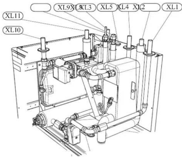
Install safety valve FL2 on XL11.
Connection to hot water heater
For HSB100 indoor unit, it is necessary to connect PT storage tank unit applying 3 way valve in order to use domestic hot water function.
For HMK100 indoor unit, 180L tank unit is integrated in indoor unit.
Housing disassembly of tank unit
Removable housing with thermal insulation facilitates transport and installation of the storage tank. Disassembly the housing in the following order (see next pages fi gure):
- Remove the Temperature gauge, plug of the heating element connector pipe and blanking plate of the inspection opening.
2 Remove the upper cover of the housing together with thermal insulation. - Remove the plugs from the connector pipes and black bushings.
- Remove the fixing screws and the strip connecting the housing jacket.
- Remove the jacket surrounding the tank (housing jacket.)
- Remove the four-piece thermal insulation.
After the installation of the storage tank in its final location, reinstall the removed components in the reverse order.
Housing and thermal insulation disassembly

Connecting hot water tank to indoor unit
CAUTION
Installation and commissioning of the storage tank shall only be done by appropriately qualified installer. The installer should inform the user of the functions of the product and provide the necessary in formation on its safe use.
Information
We recommend installing a strainer in order to protect the pumps, check valve and the components of the heating system.
■ Tank and its pipings to indoor unit must be installed indoors where the temperature wouldn't drop below 15^ C in order to prevent pipings from icing.
■ Maximum piping length between indoor unit and tank is 10 m.
■ Tank unit should be placed on firm, preferably a concrete floor or foundation.
■ Tank unit can be aligned using the adjustable feet.
■ Protection against overpressure shall be made in accordance with the relevant regulations.
■ Connect the heating system according to the installation diagram (see figure).
Installation diagram of the PT storage tank with one coil.
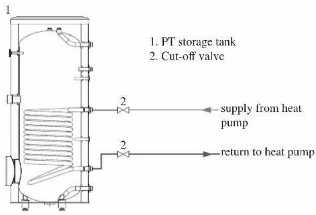
Connecting hot water tank to water main
■ Install a mixing valve if the temperature exceeds 60^ C.
■ It is recommended to install a thermostatic mixing valve for stable temperature hot water supply.
■ Connect the storage tank to the water supply system of water pressure at least 1 bar and max 10 bar. Install a pressure reducer if the pressure at the cold water inlet to the tank is higher than allowed.
■ Install a safety valve which have a maximum 10.0 bar opening pressure on the incoming domestic water line according to outline diagram in order to protect the storage tank against overpressure. Pressure increases during heating the water.
■ During heating the water, small and temporary water flow from the safety valve can occur, which indicates that the pressure has increased above the rated value, which triggered the valve. This may in no way be prevented.
■ Safety valve drain line should be installed with a decline, in an environment free of freezing and remain open to the atmosphere. The manufacturer is not responsible for flooding the room through the safety valve.
■ Blocked safety valve can cause equipment failure. Drain the outflow from the safety valve to the sewerage or drain grate.
■ See section Dockings on page 25 for outline diagram.
■ Connect the water supply system according to the installation diagram.
Installation diagram of the PT storage tank with one coil.

flowchart
graph TD
    A["1"] --> B["2"]
    B --> C["7"]
    C --> D["6"]
    D --> E["2"]
    E --> F["DHW"]
    F --> G["2"]
    G --> H["3"]
    H --> I["4"]
    I --> J["5"]
    J --> K["8"]
    K --> L["to sewerage"]
    K --> M["water supply system"]
    N["hot water circulation (optional)"] --> C
    N --> D
    N --> E
- PT storage tank
- Cut-off valve
- Safety valve
- Drain valve
- Pressure reducer (option, if the pressure in the system exceeds the allowable value)
- Strainer
- Hot water circulating pump
- Hot water expansion vessel
Information
In order to minimize the flow of water from the safety valve associated with the thermal expansion of the liquid, it is advisable to install a suitable expansion vessel at the cold water connection (see item 8.)
CAUTION
Installation of the appropriate safety valve in the cold water supply line protecting the unit against overpressure is mandatory!
CAUTION
Installation of necking of any kind (such as reducers, dirt pockets, etc.) and cut-off valves between the storage tank and the safety valve is not allowed. Only a T-pipe with a drain valve and a T-pipe with an expansion vessel may be installed in these line sections.
CAUTION
Never block the safety valve or drain line. This can cause a dangerous overpressure in the storage tank.
CAUTION
When heating water, slight, temporary discharge from the safety valve can occur. This is a correct safety valve function. Any attempt to interfere in its operati on can lead to the danger and destruction of the storage tank.
CAUTION
Never use the equipment with clogged safety valves.
Connection
After the installation and levelling the tank, follow the procedure below (for the connector pipe symbols, refer to page 19):
- Remove protecting plugs from the connector pipes
- Connect the hot water intake line (N).
- Connect the cold water supply line together with the required safety valves (G).
- If the system has the hot water circulation system, connect it to the connector pipe (L). Otherwise, plug the pipe.
- Connect the supply (J) and return (H) of the heating medium to the coil.
CAUTION
If there is an electric heating module installed in the storage tank, fill the tank with water before connecting it to the electrical installation.
Hot water circulation circuit
Hot water circulation function is available for HMK100 and PT300/500.
HMK100
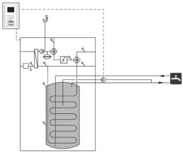
flowchart
graph TD
    A["压力传感器"] --> B["阀门"]
    B --> C["气压容器"]
    C --> D["控制阀"]
    D --> E["阀门"]
    E --> F["压力传感器"]
    F --> G["阀门"]
    G --> H["压力传感器"]
    H --> I["阀门"]
    I --> J["压力传感器"]
    J --> K["阀门"]
    K --> L["压力传感器"]
    L --> M["阀门"]
    M --> N["压力传感器"]
    N --> O["阀门"]
    O --> P["压力传感器"]
    P --> Q["阀门"]
    Q --> R["压力传感器"]
    R --> S["阀门"]
    S --> T["压力传感器"]
    T --> U["阀门"]
    U --> V["压力传感器"]
    V --> W["阀门"]
    W --> X["压力传感器"]
    X --> Y["阀门"]
To connect the circulation:
- Remove the XL5 plug from the top of the housing.
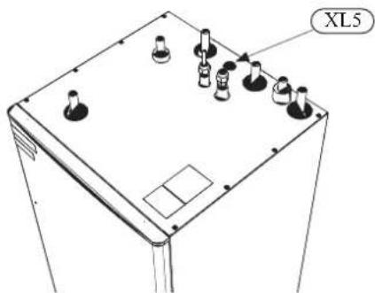
- Remove the front panel, then slide the control panel down to access the hydraulic connections.

natural_image
Technical line drawing of a mechanical assembly with no visible text or symbols- Remove the plug from the circulation pipe (XL5).
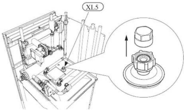
-
Install the elbow, facing the rear housing, on the circulation pipe.
-
Connect the pipe to the elbow, with the dimensions shown in the figure below, leading pipe in the top of the housing, in place of the XL5 plug. Mount the pipe insulation.

Circulation pipe dimensions (*)
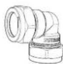
Elbow 15x15 (*)
-
At the outlet of the circulation tube, install the circulation pump and then connect its control to the RC-HY (Chapter 5 Electrical connection).
-
Install the control panel and the front panel.
(*) Prepared on site.
PT300/500
If the system has the hot water circulation system, connect it to the port L (see page 21).
Then install the Cut-off valves, circulation pump and strainer.
Connection of external heat source
External heat source, e.g. a gas or oil boiler or electric heater, can be connected on supply line of heating system (XL1).
Refrigerant circuit
Connecting refrigerant pipes
See Installation manual for outdoor unit.
Piping insulation
Install insulation on all piping in order to avoid condensation during cooling operation.
It is also strongly recommended to insulate piping for heating only application in order to avoid getting burned or reducing the heating capacity.
The thickness of the insulation should be 20mm where the relative humidity exceeds 70%.
Drain connection
HMK 100 is equipped with a condensate hose in the heat exchanger section. The hose drains all condensate away from the device to minimize the risk of damage. If necessary, the hose can be extended.

Dockings
General
Installation requirements
Hydrolution can be connected in several different ways, some of which are shown on the following pages.
| HSB100=HMK100=HSB100=HMK100 | |||
| FDCW71VNX=FDCW100VNX | |||
| Max pressure, climate system | 0.25 MPa (2.5 Bar) | ||
| Highest recommended supply/return temperature | 55/45°C | ||
| Max temperature, climate system | 65 °C | ||
| Max temperature in indoor unit | 65 °C | ||
| Max temperature from external heat source | 65 °C | ||
| Max supply temperature with compressor at outdoor temp -15°C | 58 °C | ||
| Min supply temp. cooling | 7 °C | ||
| Max supply temp. cooling | 25 °C | ||
| Min volume, climate system during heating, cooling | 50 L | 80 L | |
| Min volume, climate system during underfloor cooling | 80 L | 100 L | |
| Max flow, climate system | 0.38 L/s | 0.57 L/s | |
| Min flow, climate system, at 100% circulation pump speed | 0.19 L/s | 0.29 L/s | |
| Min flow, climate system | 0.12 L/s | 0.15 L/s | |
| Nominal system flow heating (ΔT=5K) | 0.38 L/s (8kW, 7/45°C) | 0.43 L/s (9kW, 7/45°C) | |
| Nominal system flow cooling (ΔT=5K) | 0.34 L/s (7.1kW, 35/7°C) | 0.38 L/s (8kW, 35/7°C) | |
External circulation pump must be used when the pressure drop in the system is greater than the available external pressure. In such cases, a bypass line with non-return valve must be installed.
Use an overflow valve if system flow cannot be guaranteed.
Symbol key
| MeaningSymbol | |
| ↑ | Venting valve |
| ☒ | Shut-off valve |
| ☒ | Non-return valve |
| ☒ | Control valve |
| ☒ | Safety valve |
| ♀ | Temperature sensor |
| Expansion vessel | |
| ◎ | Pressure gauge |
| ◎ | Circulation pump |
| Shunt / shuttle valve | |
| ◎ | Fan |
Docking alternatives
Heating system can be constructed in several different ways combining indoor unit, tank, control unit and other accessories.
For further option information, see page 84.
In the system example shown on the following page, heating, hot water as well as cooling operation are available.
Additional heating is helpful on the cold day of the year as the energy from the air is reduced. It is also recommended as back-up in case the heat pump operation is blocked for any reason (e.g. ambient temperature exceeds the operation limit of heat pump).
NOTE
The heating medium side and the hot water side must be fitted with the necessary safety equipment in accordance with the applicable regulations.
This is the outline diagram. Actual installations must be planned according to applicable standards.
Explanation
AA25 Controller
BT1 Outdoor sensor 1)
BT6 Temperature sensor, hotwater charging 1)
BT7 Temperature sensor, hot water top 1)
BT25 Temperature sensor, external supply line 1)
BT50 Room sensor
BT63 Temperature sensor, external supply line after electric heater
BT71 Temperature sensor, external return line 1)
GP10 Circulation pump, Heating medium
QN10 Reversing valve, Hot water/Heating medium 2)
EB1 Additional heat
EB1 Immersion heater
KA1 Auxiliary relay/Contactor 2)
EB101 Heat pump system
BP4 Pressure sensor, condensor 3)
BT3 Temperature sensor, return line 3)
BT12 Temperature sensor, condenser supply line 3)
BT15 Temperature sensor, fluid pipe 3)
EB101 Heat pump
FL10 Safety valve
GP12 Charge pump 2)
HQ1 Particle filter 3)
QM1 Drain valve, Heating medium
QM31 Shut-off valve, Heating medium, Flow
QM32 Shut off valve, Heating medium, Return
QM43 Shut-off valve
EQ1 Cooling system
BT64 Temperature sensor, cooling supply line 2)
CP6 Single jacket accumulator tank, cooling
GP13 Circulation pump, cooling
QN12 Reversing valve, Cooling/Heating ^2)
Miscellaneous
CM1 Expansion vessel closed, Heating medium
CP5 Buffer vessel
CP10 Accumulator tank with hotwater heating
EB20 Immersion heater
FL2 Safety valve, Heating medium
KA1 Auxiliary relay/Contactor
RN10 Trim valve
1) Included in and supplied with controller
2) Included in and supplied with accessory
3) Included in indoor unit
Installation with indoor unit HSB100, tank PT300/500, controller RC-HY20/40 with step controlled additional heat before reversing valve for hot water and cooling function (4 pipe system)

flowchart
graph TD
    A["EQ1"] --> B["-AA25"]
    B --> C["CP6-CP6"]
    C --> D["-BP13"]
    D --> E["-BT64"]
    E --> F["--EA25"]
    F --> G["--BA25"]
    G --> H["--BT1"]
    H --> I["--EB101"]
    I --> J["--EB101"]
    J --> K["--EZ101"]
    K --> L["--XL14"]
    L --> M["--EZ102"]
    M --> N["--QM31"]
    N --> O["--QM32"]
    O --> P["--IJQ1"]
    P --> Q["--FL10"]
    Q --> R["--QM1"]
    R --> S["--FL10"]
    S --> T["--QM43"]
    T --> U["--HQ1"]
    U --> V["--QM43"]
    V --> W["--FI2"]
    W --> X["--CM1"]
    X --> Y["--CP10"]
    Y --> Z["--AA25-BT7"]
    Z --> AA["--AA25-BT6"]
    AA --> AB["--RN10"]
    AB --> AC["--AA25-QN10"]
    AC --> AD["--AB1"]
    AD --> AE["-KA1"]
    AE --> AF["-EB1"]
    AF --> AG["-BT63"]
    AG --> AH["--EQ1-QN12"]
    AH --> AI["--EB101"]
    AI --> AJ["--EB101"]
NOTE
Not all components are shown in this outline diagram.
Controller (AA25) starts and stops the heat pump (EB101) to meet the heating and hot water demand.
At simultaneous heating and hot water demand, the reversing valve (AA25-QN10) switches periodically between the climate system and the water heater/accumulator tank (CP10). When the hot water heater/accumulator tank is fully charged, the reversing valve switches to the climate system.
Additional heat (EB1) is turned on automatically when the heating demand exceeds the heat pump capacity. This is used for both heating and charging hot water.
The additional heat can also be used for water heater when a higher temperature is required than the heat pump can produce.
During cooling operation, the reversing valve (EQ1-QN12) switches to the cooling system (EQ1). If several simultaneous demands occur while there is a cooling demand, the system reacts differently. In the event of a hot water demand, the reversing valve switches back and hot water is produced until the demand is fulfilled. In the event of a heating demand, the reversing valve switches periodically between cooling and heating. If the cooling demand is met, the reversing valve switches back to basic mode (heating/hot water).
Indoor unit HSB100, tank PT300/500, controller RC-HY20/40 with step controlled additional heat after reversing valve for hot water and cooling function (4 pipe system)
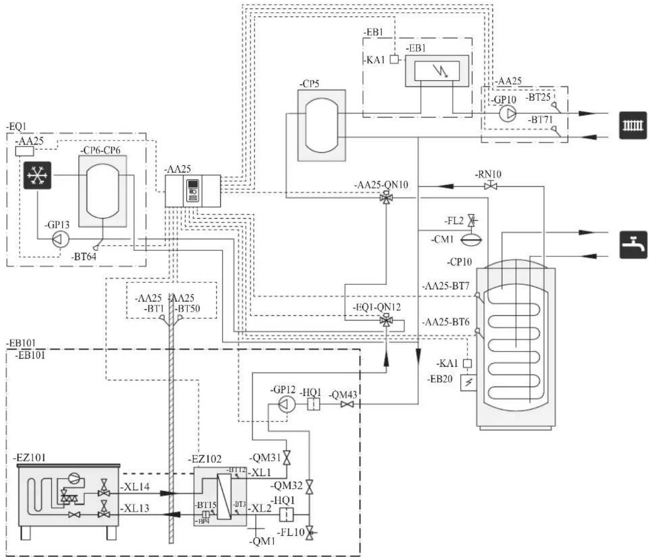
flowchart
graph TD
    A["EQ1"] --> B["AA25"]
    B --> C["CP6-CP6"]
    C --> D["-GP13"]
    D --> E["-BT64"]
    E --> F["AA25"]
    F --> G["CP5"]
    G --> H["-KA1"]
    H --> I["EB1"]
    I --> J["BA"]
    J --> K["BB1"]
    K --> L["AA25-QN10"]
    L --> M["-RN10"]
    M --> N["FL2"]
    N --> O["CM1"]
    O --> P["CP10"]
    P --> Q["AA25-BT7"]
    Q --> R["AA25-BT6"]
    R --> S["KA1"]
    S --> T["EB20"]
    T --> U["BL"]
    U --> V["BL101"]
    V --> W["EB101"]
    W --> X["EA101"]
    X --> Y["BL14"]
    Y --> Z["XL13"]
    Z --> AA["AZ102"]
    AA --> AB["-BM31"]
    AB --> AC["-BM32"]
    AC --> AD["-BM15"]
    AD --> AE["-BM4"]
    AE --> AF["-BM15"]
    AF --> AG["-BM3"]
    AG --> AH["-BM10"]
    AH --> AI["BL10"]
NOTE
Not all components are shown in this outline diagram.
This installations alternative is suitable for more complex installations with a focus on comfort.
Controller (AA25) starts and stops the heat pump (EB101) to meet the heating and hot water demand of the installation.
At simultaneous heating and hot water demand the reversing valve (AA25-QN10) switches periodically between the climate system and the water heater/accumulator tank (CP10). When the hot water heater/accumulator tank is fully charged, the reversing valve switches to the climate system.
Additional heat (EB1) is turned on, automatically when the heating demand exceeds the heat pump capacity.
Immersion heater (EB20) in the water heater/accumulator tank is used during the time to produce hot water if the heat pump is used for heating at the same time.
The immersion heater (EB20) can also be used if a higher temperature of hot water is required than the heat pump can produce.
During cooling operation, the reversing valve (EQ1-QN12) switches to the cooling system (EQ1). If several simultaneous demands occur while there is a cooling demand, the system reacts differently. In the event of a hot water demand, the reversing valve switches back and hot water is produced until the demand is fulfilled. In the event of a heating demand, the reversing valve switches periodically between cooling and heating. If the cooling demand is met, the reversing valve switches back to basic mode (heating/hot water).
Installation with indoor unit HMK100 for hot water and cooling function (4 pipe system)
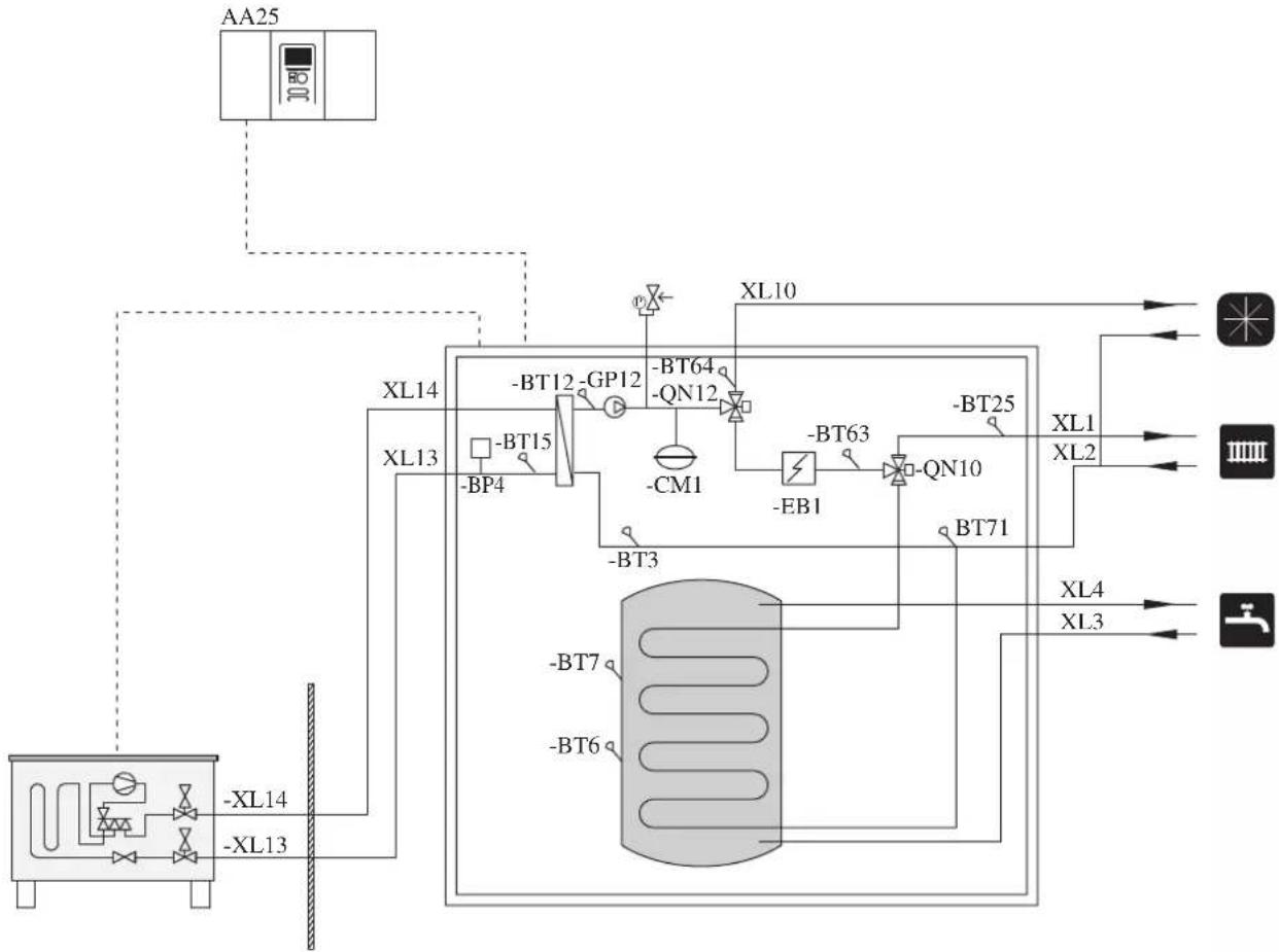
flowchart
graph TD
    A["AA25"] --> B["XL14"]
    A --> C["XL13"]
    B --> D["XL10"]
    C --> E["XL14"]
    D --> F["-BT64"]
    D --> G["-GP12"]
    D --> H["-BM1"]
    E --> I["-BT12"]
    E --> J["-BM4"]
    E --> K["-BM7"]
    E --> L["-BM9"]
    E --> M["-BM10"]
    E --> N["-BM11"]
    E --> O["-BM12"]
    E --> P["-BM13"]
    E --> Q["-BM14"]
    E --> R["-BM15"]
    E --> S["-BM16"]
    E --> T["-BM17"]
    E --> U["-BM18"]
    E --> V["-BM19"]
    E --> W["-BM20"]
    E --> X["-BM21"]
    E --> Y["-BM22"]
    E --> Z["-BM23"]
    E --> AA["-BM24"]
    E --> AB["-BM25"]
Controller (AA25) starts and stops the heat pump (EB101) to meet the heating and hot water demand. At simultaneous heating and hot water demand, the reversing valve (QN10) swithes periodically between the climate system and the hot water heater. When the hot water heater is fully charged, the reversing valve swithes to the climate system.
Additional heat (EB1) is turned on automatically when the heating demand exceeds the heat pump capacity. This is used for both heating and charging water heater.
The additional heat can also be used for water heater when a higher temperature is required than the heat pump can produce.
Cooling is controlled by the sensor BT64, and the reversing valve (QN12) swithes to the cooling system. If several simultaneous demands occur while there is a cooling demands, the system reacts differently. In the event of a hot water demand, the reversing valve switches back and hot water is produced until the demand is fulfilled. In the event of heating demand, the reversing valve switches periodically between cooling and heating. If the cooling demand is met, the reversing valve switches back to basic mode (heating/hot water).
Electrical installation
General
Indoor unit must be installed via an isolator switch in accordance with the local codes and regulations.
For HMK100, electrical equipments, except outdoor air sensor, room sensor, current transformers and outdoor unit has been connected at the factory.
■ Disconnect the indoor unit, outdoor unit and control unit before insulation testing of the house wiring.
■ If the building is equipped with an earth-fault breaker, Hydrolution should be equipped with a separate one.
■ For the electrical wiring diagram, see page 85.
■ Do not lay communication, sensor or signal cables for external connection close to high voltage lines.
■ Minimum cross section of communication, sensor or signal cables for external connection must be 0.5mm^2 up to 50 m, for example EKKX, LiYY or equivalent.
■ Use screened three core cable for communication between controller (RC-HY20/40) and indoor unit (HSB100/HMK100).
■ When laying cables into indoor units and controllers, be sure to route the cable grommet (UB1 AND UB2).
■ Be careful to route cables not to be damaged by metal edge or trapped by panels.
■ Outdoor unit is equipped with a single phase compressor. This means that phase L3 is loaded with up to A during compressor operation.
| Outdoor unit α | |
| FDCW71VNX 16 | |
| FDCW100VNX 23 |
NOTE
Electrical installation and service must be carried out under the supervision of a qualified electrician.
Turn off the circuit breaker before carrying out any servicing.
Electrical installation and wiring must be carried out in accordance with the stipulations in force.
Make sure to turn off the power supply during installation.
NOTE
Do not turn on the power on control until the boiler is filled with water.
The circulation pump and immersion heater may become damaged.
NOTE
If the power supply cable is damaged, only authorised person may replace it to avoid danger or damage.
Principle diagram, electrical installation
HSB100

flowchart
graph TD
    A["PEN L1 L2 L3"] --> B["Electrical distribution unit"]
    B --> C["Isolator switch"]
    C --> D["FDCW71/100 (Outdoor unit)"]
    C --> E["HSB100 (Indoor unit) (Controller)"]
    C --> F["RC-HY20/40"]
    C --> G["Electric heater"]
    C --> H["Circulation pump"]
    C --> I["3way valve"]
    B --> J["Power and sensor cable"]
    B --> K["Communication cable"]
| Cable size | |
| Power – Indoor unit 3core, 1. | .5mm ^2 (power cable) |
| Power – Outdoor unit 3core, | 2.5mm ^2 (power cable) |
| Indoor unit – Outdoor unit | 2core, 1.5mm ^2 (communication cable) |
| Indoor unit – Controller | 3core, 0.5mm ^2 , LiYY, EKKX or equivalent (communication cable) |
The cable size shown on the above table is reference value.
Choose appropriate size according to local laws and regulations.
HMK100
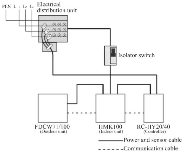
flowchart
graph TD
    A["Electrical distribution unit"] --> B["FDCW71/100 (Outdoor unit)"]
    A --> C["IIMK100 (Indoor unit)"]
    A --> D["RC-HY20/40 (Controller)"]
    B --> E["Isolator switch"]
    C --> E
    D --> E
    style A fill:#f9f,stroke:#333
    style B fill:#ccf,stroke:#333
    style C fill:#ccf,stroke:#333
    style D fill:#ccf,stroke:#333
| Cable size | |
| Power – Indoor unit 5core, 2 | 2.5mm (power/communication cable) |
| Indoor unit – Outdoor unit | 5core, 2.5mm^2 (power/communication cable) |
| Indoor unit – Controller | 3core, 1.5mm^2 (power cable) 3core, 0.5mm^2, LiYY, EKKX or equivalent (communication cable) |
The cable size shown on the above table is reference value.
Choose appropriate size according to local laws and regulations.
Electrical components
HSB100

Explanation
AA23 Communication board
AA23-F3 Fuse for external heating cable
AA23-S3 DIP switch, addressing of outdoor unit
AA23-X1 Terminal block, incoming supply, connection of KVR
AA23-X4 Terminal block, communication with indoor module / control module
AA23-X100 Terminal block, communication outdoor module FDCW
HMK100
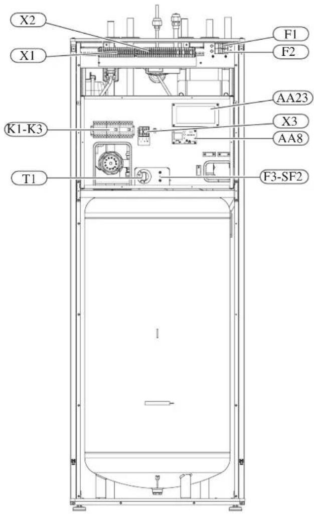
Explanation
X1 Terminal block, sensors
X2 Terminal block, power supply
X3 Terminal block
SF1 Controller switch
K1-K3 Submersible heater contact
T1 Thermostat, standby mode
F3 Temperature limiter
AA8 Titanium anode board
AA23 Communication board
F1 Circuit breaker, outdoor unit
F2 Circuit breaker, controller
UBI Cable grommet
UB2 Cable grommet
F3-SF2 Reset botton, temperature limiter
Temperature limiter
Temperature limiter (F3) cuts off the power supply of the electrical heating module if the temperature increases to the range of approximately 87 °C, and can be reset manually.
Resetting
Temperature limiter (F3) is accessible behind the front cover. Temperature limiter is reset by strong pressing of the button (F3-SF2) using a small screwdriver.
Press the button, max. 15 N (approx. 1.5 kg).
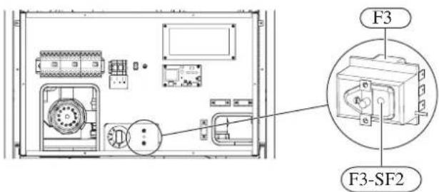
RC-HY20
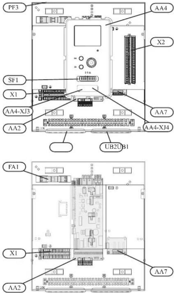
Explanation
AA2 Base card
AA4 Display unit
AA4-XJ3 USB socket
AA4-XJ4 Service outlet (No function)
AA7 Extra relay circuit board
FA1 Miniature circuit-breaker
X1 Terminal block, incoming electrical supply
X2 Terminal block, control signal circulation pump, sensors AUX inputs and heat pump
SF1 Switch
PF3 Serial number plate
UB1 Cable grommet, incoming supply electricity, power for accessories
UB2 Cable grommet, signal
RC-HY40
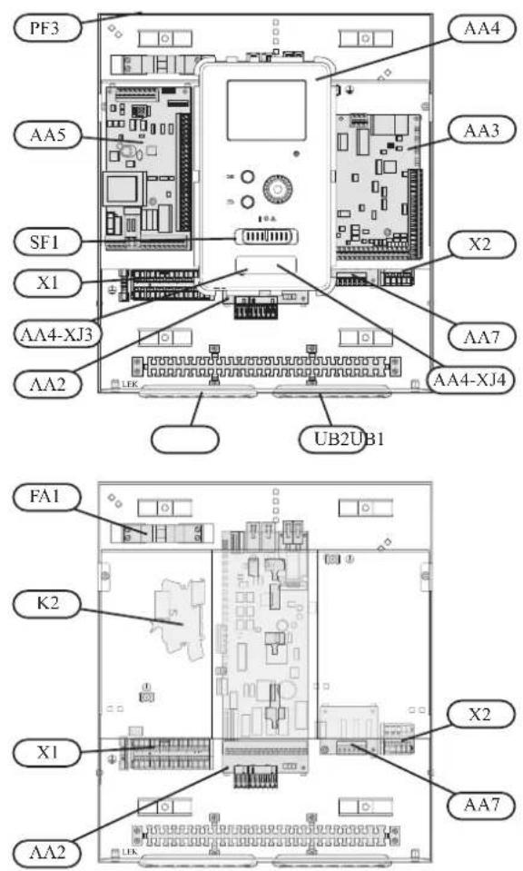
Explanation
AA2 Base card
AA3 Input circuit board
AA4 Display unit
AA4-XJ3 USB socket
AA4-XJ4 Service outlet (No function)
AA5 Accessory card
AA7 Extra relay circuit board
FA1 Miniature circuit-breaker
K2 Emergency mode relay
X1 Terminal block, incoming electrical supply
X2 Terminal block, AUX4 - AUX6
SFI Switch
PF3 Serial number plate
UB1 Cable grommet, incoming supply electricity, power for accessories
UB2 Cable grommet, signal
Accessibility, electrical connection for controller
The cover of the control module is opened using a Torx 25 screwdriver. Assembly takes place in the reverse order.

NOTE
The cover to access the base board is opened using a Torx 25 screwdriver

natural_image
Technical line drawing of an internal electronic device casing with ports and connectors (no text or symbols)The display may need to be moved for easier access when connecting electrics. This is easily done by following these steps.
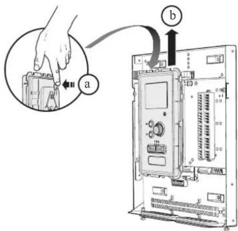
- Press in the catch on the upper rear side of the display unit towards you (a) and move the display unit upwards (b) so that the mountings unhook from the panel.
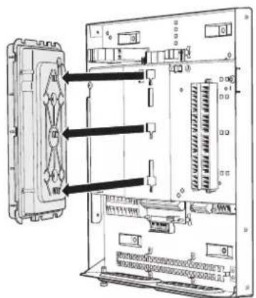
- Lift the display unit from its mountings.
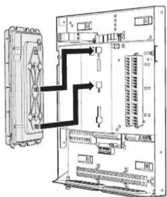
- Align the two lower mountings on the reverse of the display unit with the two upper holes in the panel as illustrated.
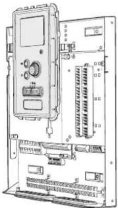
natural_image
Technical line drawing of an electronic device chassis with ports and connectors (no text or symbols)-
Secure the display on the panel.
-
When the electrical connection is ready the display must be reinstalled with three mounting points again, otherwise the front cover cannot be installed.
Cable lock
Use a suitable tool to release/lock cables in the terminal block.
HSB100, RC-HY20/40
Terminal block on the electrical card

Terminal block

HMK100
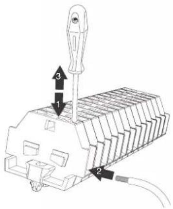
Connection
NOTE
To prevent interference, unscreened communication and/or sensor cables to external connections must not be laid closer than 20 cm from high voltage cables.
HSB100
Power supply
In case of HSB100, power supply is made to indoor unit, outdoor unit and controller separately. 230V 1AC 50Hz is applied.
For indoor unit, incoming supply is connected on AA23-X1 terminal.

For outdoor unit, incoming supply is connected on TB terminal. See figure on Connection between indoor and outdoor unit.
Connection between indoor and outdoor unit
The communication cable between indoor and outdoor unit is connected between terminal AA23-X100 in indoor unit and TB in outdoor unit. Screened 2 core cable is recommended.
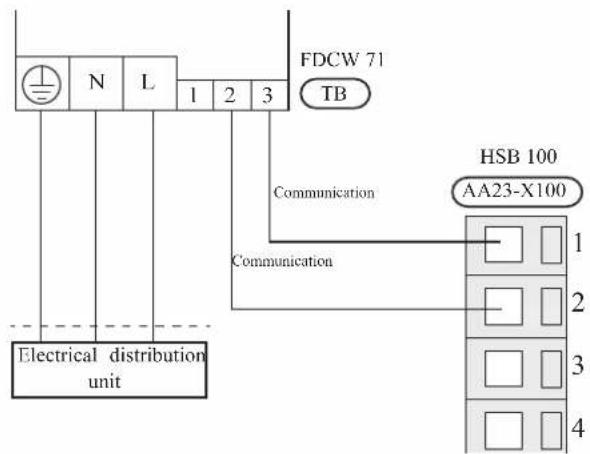
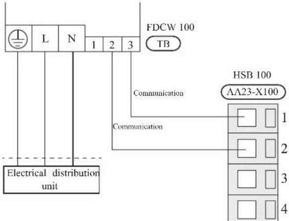
Connection between indoor unit and controller
See Connection for RC-HY20/40
Cascade connection setting
In case of cascade connection system, it is necessary to allot unique address to each indoor unit. Set the dip switch S3-1, -2 and -3 according to the following table.
| Address S3:1 | S3:2 S3:3 | ||
| 1 OFF OFF OFF | |||
| 2 On OFF OFF | |||
| 3 OFF On OFF | |||
| 4 On On OFF | |||
| 5 OFF OFF On | |||
| 6 On OFF On | |||
| 7 OFF On On | |||
| 8 On On On | |||
Recommended fuse size for HSB100
The recommended fuse size shown in the following table is reference value. Choose appropriate size according to local laws and regulations.
| Fuse size | |
| Indoor unit (HSB100) 6A / 230V 1AC 50Hz | |
| Outdoor unit (FDCW71VNX) 20A / 230V 1AC 50Hz | |
| Outdoor unit (FDCW100VNX) 30A / 230V 1AC 50Hz | |
| Controller (RC-HY20/40) 10A/ 230V 1AC 50Hz | |
| Electric heater (ELK9M)(reference) | 16 A/400V 3NAC 50Hz |
Recommended cable size for HSB100
The recommended cable size shown in the following table is reference value. Choose appropriate size according to local laws and regulations.
| Cable size | |
| Power – Indoor unit 3core, 1.5mm ^2 (power cable) | |
| Power – Outdoor unit | 3core, 2.5mm ^2 (power cable) |
| Indoor unit – Outdoor unit | 2core, 1.5mm ^2 (communication cable) |
| Indoor unit – Controller | 3core, 0.5mm ^2 , LiYY, EKKX or equivalent (communication cable) |
HMK100
Circuit breaker
HMK100 is equipped with internal circuit breakers to protect the system and components. The circuit breaker F1 protects outdoor unit and F2 protects controller.
Power supply
In case of HMK100, power supply is made to indoor unit, and further connected to outdoor unit and controller. 400V 3NAC 50Hz is applied.
Connect power supply cable to the port for power supply on X2 terminal as shown below.

Connection between indoor and outdoor unit
For interconnection cable between indoor unit and outdoor unit, connect 2, 3, L, N and PE port for outdoor unit on terminal on HMK100 to 2, 3, L, N, and ⏱ port on FDCW71/100 respectively according to the below figure.
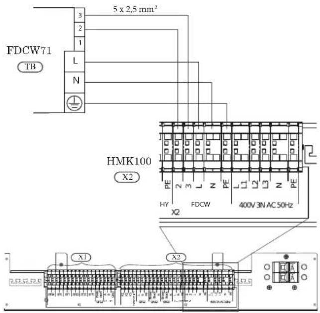
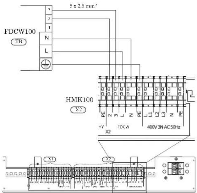
Connection between indoor unit and controller
See Connection for RC-HY20/40.
Recommended fuse size for HMK100
The recommended fuse size shown in the following table is reference value. Choose appropriate size according to local laws and regulations.
| Fuse size | |
| Indoor unit (HMK100) 25A / 400V 3NAC 50Hz | |
Recommended cable size for HMK100
The recommended fuse size shown in the following table is reference value. Choose appropriate size according to local laws and regulations.
| Cable size | |
| Power – Indoor unit 5core, 2.5mm ^2 (power/communication cable) | |
| Indoor unit – Outdoor unit 5core, 2.5mm ^2 (power/communication cable) | |
| Indoor unit – Controller 3core, 1.5mm ^2 (power cable)3core, 0.5mm ^2 , LiYY, EKKX or equivalent (communication cable) | |
RC-HY20/40
Cable connection is different according to the system structure. Refer to the connection method according to the indoor unit.
Power supply
HSB100
Connect power cable on X1 terminal as shown below.
RC-HY 20/40 must be installed via an isolator switch with a minimum breaking gap of 3 mm. Minimum cable area must be sized according to the fuse rating used.
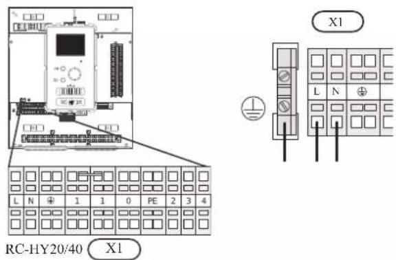
HMK100
Power is supplied through indoor unit. Connect the port L, N and ⏻ on X1 terminal on RC-HY20/40 to the port L, N and PE for controller on X2 terminal on HMK100 respectively as shown below.
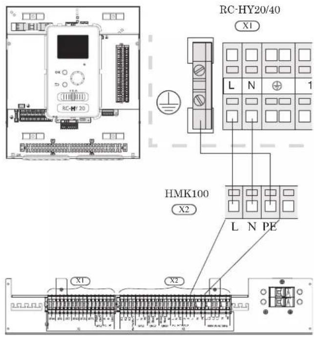
Connection between controller and indoor unit HSB100
Signal cable is connected between controller and indoor unit with screened 3 core cable for HSB100. Choose correct terminal according to the type of controller as shown below.
Connect the port 19(A), 20(B) and 21(GND) on X2 terminal on RC-HY20 to the port 1, 2 and 3 on X4 terminal on AA23 board on HSB100 respectively.
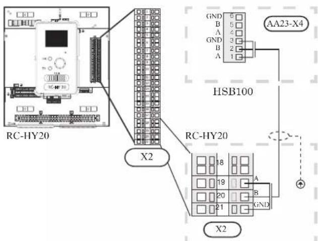
Connect the port 1(A), 2(B) and 3(GND) on X4 terminal on AA5 board on RC-HY40 to the port 1, 2 and 3 on X4 terminal on AA23 board on HSB100 respectively.
In case several systems are connected to one controller, connect the port 4, 5 and 6 on X4 terminal on AA23 board on HSB100 close to the controller to the port 1, 2 and 3 on X4 terminal on AA23 board on another HSB100.
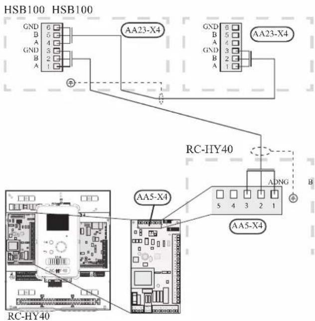
HMK100
Communication cable and pump cable are connected between controller and indoor unit, with screened 3 core cable for HMK100. Choose correct terminal according to the type of controller as shown below.
Communication cable
Connect the port 19(A), 20(B) and 21(GND) on X2 terminal on RC-HY20 to the port A, B and GND for EB101 on X1 terminal on HMK100 respectively.
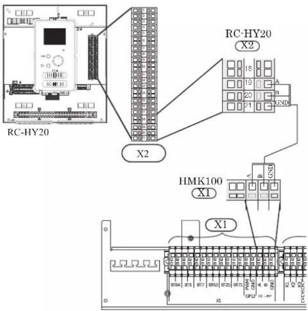
Connect the port 1(A), 2(B) and 3(GND) on X4 terminal on AA5 board on RC-HY40 to the port A, B and GND for EB101 on X1 on HMK100 respectively.
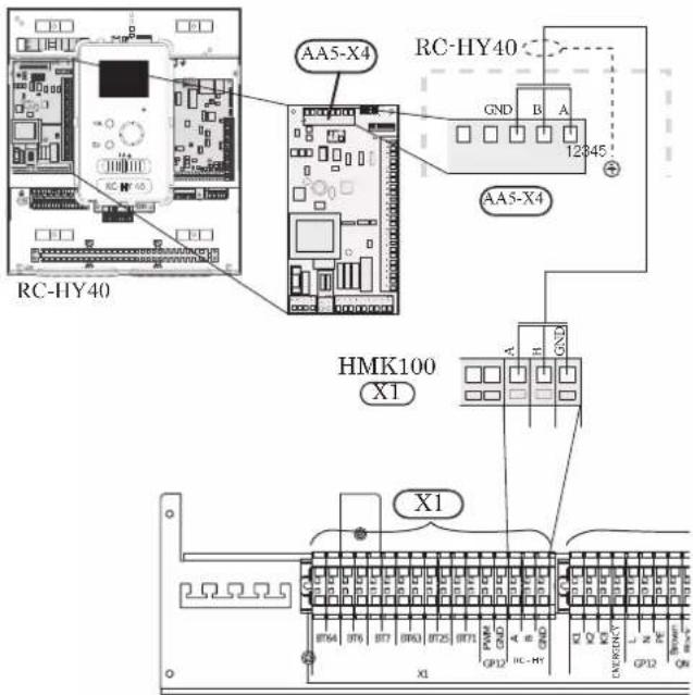
Connection between controller and circulation pump (GP12)
HSB100
For HSB100, circulation pump (GP12) is installed outside of indoor unit. Choose correct terminal according to the type of controller.
Connect the port 5, 6 and 7 on X4 terminal on AA2 board on RC-HY20/40 to the port PE, N and L on circulation pump respectively. Control signal cable is connected between the port 1 and 2 on X2 terminal on RC-HY20 and PWM and GND on circulation pump respectively as shown below.
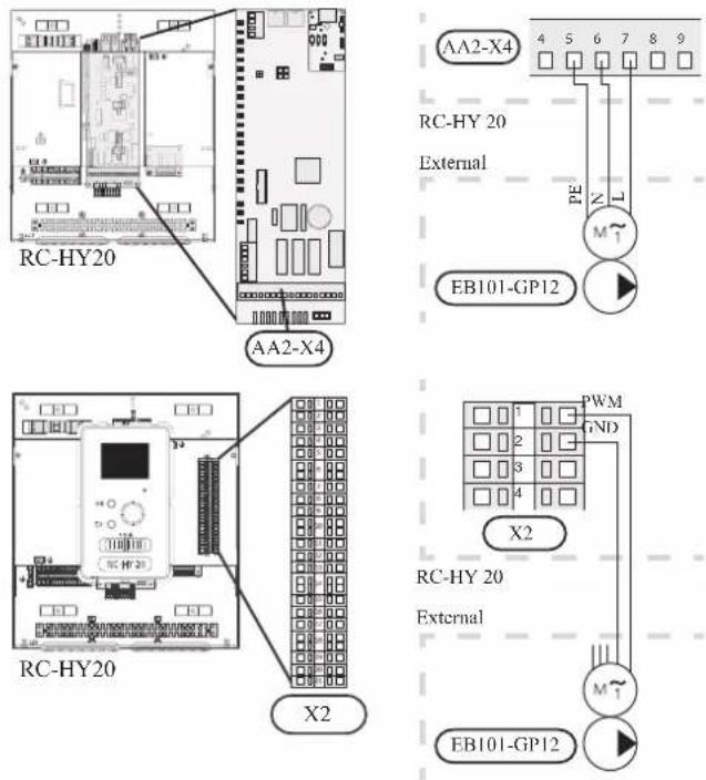
Connect the port 5, 6 and 7 on X4 terminal on AA2 board on RC-HY40 to the port PE, N and L on circulation pump (EB101-GP12) respectively. Control signal cable is connected between the port 7 and 8 on X4 terminal on AA3 board on RC-HY40 and GND and PWM on circulation pump respectively as shown below.
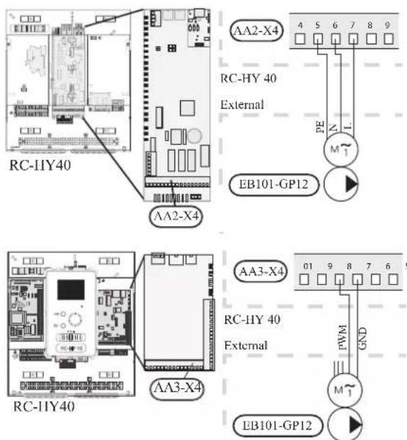
RC-HY40 can connect and control up to two pumps. Connect the port 12, 13 and 15 on X4 terminal on AA2 board on RC-HY40 to the port PE, N and L on second circulation pump (EB102-GP12) respectively. Control cable is connected between the port 5 and 6 on X4 terminal on AA3 board on RC-HY40 and GND and PWM on circulation pump respectively as shown below.
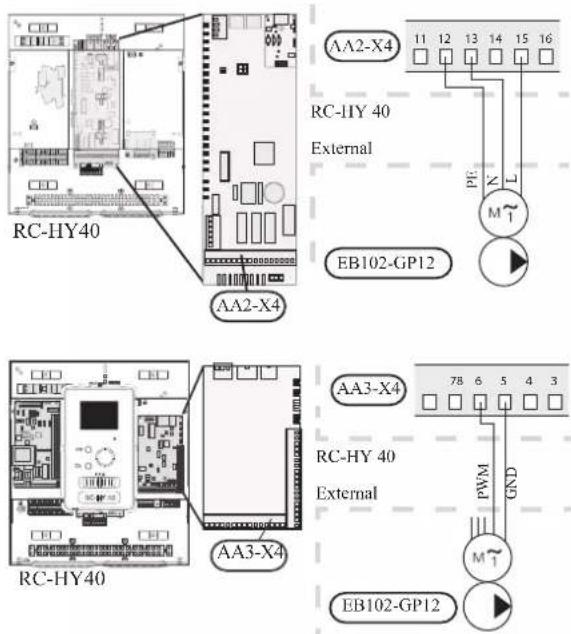
HMK100
HMK100 is equipped with circulation pump (GP12). Choose correct terminal according to the type of controller.
Connect the port 5, 6 and 7 on X4 terminal on AA2 board to the port L, N and PE for GP12 on X2 terminal on HMK100 respectively.
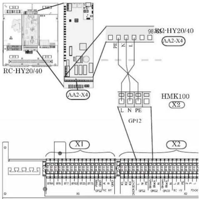
Also, connect the port 1 and 2 on X2 terminal to the port PWM and GND for GP12 on X1 terminal on HMK100 respectively as shown below.
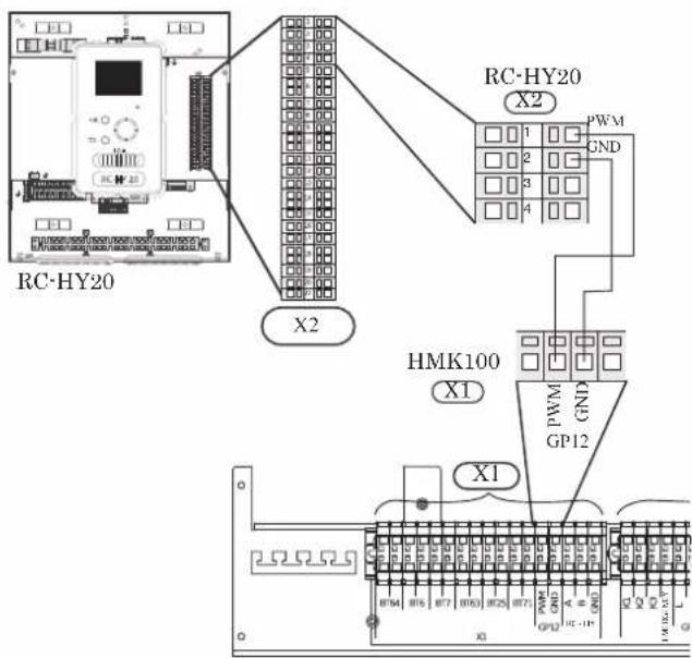
Connect the port 5, 6 and 7 on X4 terminal on AA2 board to the port L, N and PE for GP12 on X2 terminal on HMK100 respectively (same as with RC-HY20).
Also, connect the port 7 and 8 on X4 terminal on AA3 board to the port PWM and GND for GP12 on X1 terminal on HMK100 respectively as shown below.
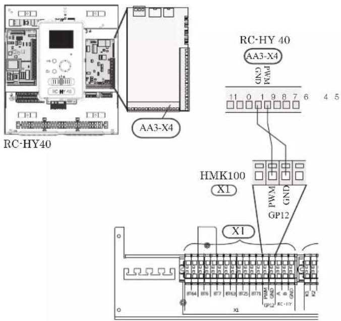
Connection between controller and 3-way valve (QN10/QN12)
3-way valve is used for switching heating / hot water production (QN10), or switching heating / cooling (QN12). Install appropriate valves according to the system structure on site.
HSB100
HSB100 is not equipped with 3-way valve. Install the valves on right position according to the diagram and connect wires on appropriate port according to the type of controller.
• 3-way valve for Heating / Hot water (QN10)
Connect the N, Control and L wire on 3-way valve to the port 2, 3 and 4 on X4 terminal on AA2 board on RC-HY20/40 respectively as shown below.
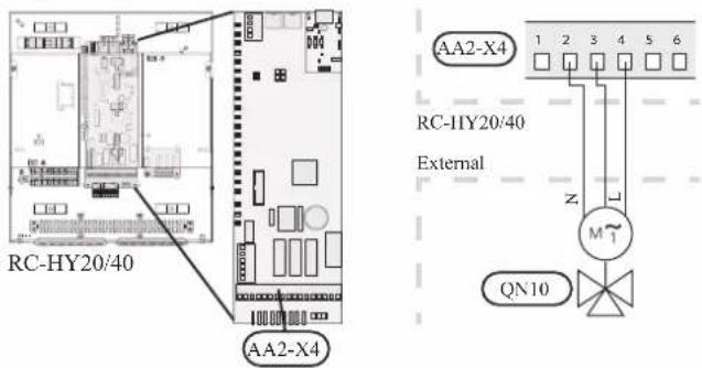
• 3-way valve for Heating / Cooling (QN12)
QN12 can be controlled with potential free variable relay. Connect L and Control wire on 3-way valve to the port 15 and 16 on X4 terminal on AA2 board on RC-HY20 respectively. Also, connect L and N wire to power supply as shown below.
Additional setting is necessary in menu 5.4. See Menu system for details.
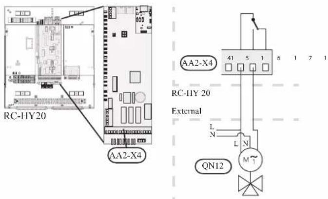
CAUTION
The relay outputs can have a max load of 2 A at resistive load (230V AC).
• 3way valve for Heating / Hot water (QN10)
5HIHU WR ZD\ YDOYH FRQQHFWLRQ IRU +6%
• 3 way valve for Heating / Cooling (QN12)
41 FDQ EH FRQWUROOHG ZLWK SRWHQWLDO IUHH YDULDEOH UHOD
&RQQHFW / DQG &RQWURO ZLUH RQ ZD\ YDOYH 3way valve for heating & Hotwater (QN10)
12 RQ ; WHUPLQDO RQ \\ ERDUG RQ 5& +<
\$OVR FRQQHFW / DQG 1 ZLUH WR SRZHU VXSSO
HMK100
+0. LV HTXLSSHG ZLWK ERWK 41 IRU VZLWF
KRW ZDWHU +< DQG 41 IRU VZLWFKLQJ KHDWLQJ
ZLUHV RQ DSSURSULDWH SRUW DFFRUGLQJ WR WKH
H 3way valve for heating & Hot water (QN10)
&RHOHEWLYWH SRUW
DQG RQ ; WHUPLQI
CAUTION
The relay outputs may be subjected to a max load of 2A at resistive load (230V AC).
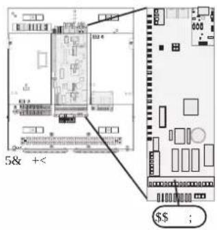
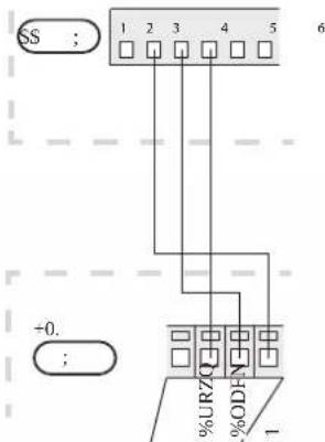
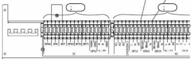
• 3 way valve for Heating / Cooling (QN12)
WHUPLQDO RQ +0. UHVSHFWLYHO\ SOVR FRQQH
; WHUPLQDO RQ 5& +< WR 1 SRUW IRU 41 RO
+0. ,Q DGGLWLRQ FRQQHFW WKH SRUW RQ
SRUW RQ ; WHUPLQDO RQ \\ ERDUG RQ 5& +
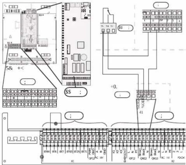
• 3way valve for Heating / Hot water (QN10)
Refer to 3-way valve connection for HMK100 with RC-HY20.
• 3 way valve for Heating / Cooling (QN12)
Connect the port C and NO on X7 terminal on AA3 board on RC-HY40 to the port Brown and Black for QN12 on X2 terminal on HMK100 respectively. Also, connect the port 0 on X1 terminal on RC-HY40 to N port for QN12 on X2 terminal on HMK100. In addition, connect the port 1 on X1 terminal to the port C on X7 terminal on AA3 board on RC-HY40.
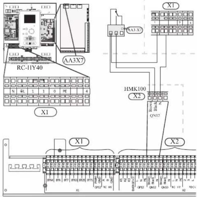
Connection between controller and sensors
Sensor connection is different according to the combination of indoor unit and controller. Refer to the appropriate combination mentioned below.
Use two-core cable with a minimum 0.5mm2 cross section.
Regarding other sensors not mentioned in this chapter, refer to page 49, Optional connections.
- Ambient air temperature sensor BT1
Install ambient air temperature sensor (BT1) in the shade on a wall-facing north or north-west, so it is unaffected by the morning sun.
Connect the sensor to the port 3 and 6 on X2 terminal.
If a conduit is used it must be sealed to prevent condensation in the sensor capsule.
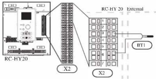
• Hot water charging sensor BT6 (tank bottom)
The temperature sensor, hot water charging (BT6) is placed in the submerged tube on the water heater.
Connect the sensor to the port 5 and 6 on X2 terminal.
Hot water charging is activated in menu 5.2 or in the start guide.
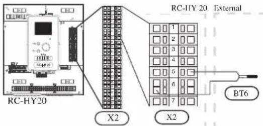
• Hot water sensor BT7 (tank top)
A temperature sensor for hot water top (BT7) can be connected to RC-HY20 to show the water temperature at the top of the tank (if it is possible to install a sensor at the top of the tank).
Connect the sensor to the port 4 and 6 on X2 terminal.
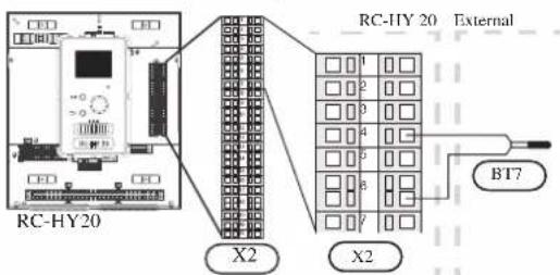
• Temperature sensor BT63, outlet at additional heater
This sensor is used in case electric heater is placed before 3-way valve (QN10) for switching heating/hot water (see page 26 for diagram).
Connect temperature sensor, external supply after electric heater (BT63) to the port 9 and 10 on terminal X2.
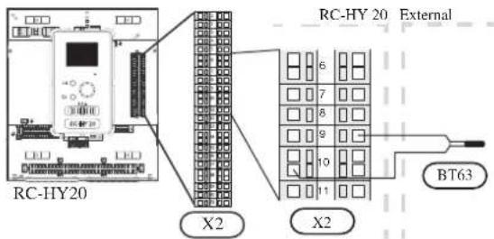
• Temperature sensor BT25, outlet for heating
This sensor is used in case electric heater is placed after 3 way valve (QN10) for switching heating/ hot water (see page 27 for diagram).
Connect temperature sensor, external supply (BT25) to the port 8 and 10 on X2 terminal.
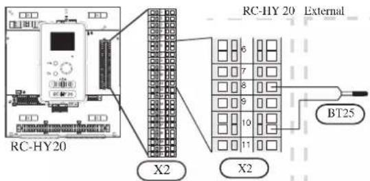
• Temperature sensor BT71, return line for heating
This sensor is used in case electric heater is placed after 3 way valve (QN10) for switching heating/ hot water (see page 27 for diagram).
For connection, see page 50, AUX inputs.
• Temperature sensor BT64, outlet for cooling
This sensor is used in case cooling application is required.
For connection, see page 51, AUX inputs.
- Ambient air temperature sensor BT1
Refer to the connection RC-HY20 with HSB100.
• Hot water charging sensor BT6 (tank bottom)
The temperature sensor, hot water charging (BT6) is placed at the bottom part of the water heater. Connect the port 5 and 6 on X2 terminal on RC-HY20 to the port BT6 on X1 terminal on HMK100.
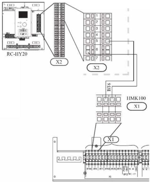
• Hot water sensor BT7 (tank top)
The temperature sensor, hot water top (BT7) is placed at the top of the water heater. Connect the port 4 and 6 on X2 terminal on RC-HY20 to the port BT7 on X1 terminal on HMK100.
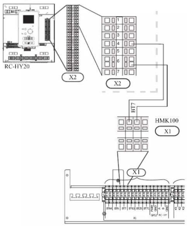
• Temperature sensor BT63, outlet at additional heater
The temperature sensor BT63 is placed on the outlet at additional heater. Connect the port 9 and 10 on X2 terminal on RC-HY20 to the port BT63 on X1 terminal on HMK100.
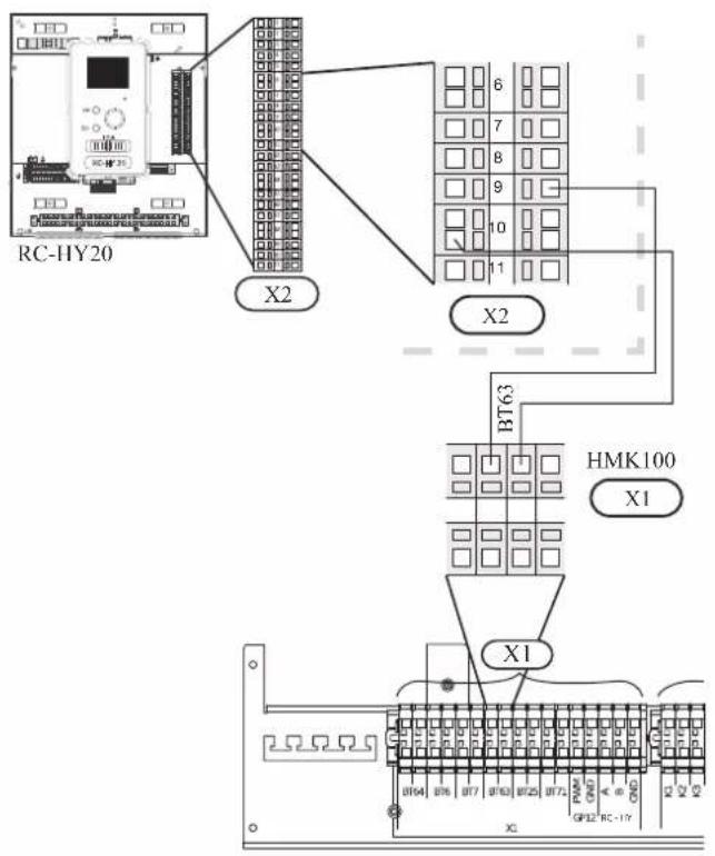
• Temperature sensor BT25, outlet for heating
The temperature sensor BT 25 is placed on the supply line for heating. Connect the port 8 and 10 on X2 terminal on RC-HY20 to the port BT25 on X1 terminal on HMK100.
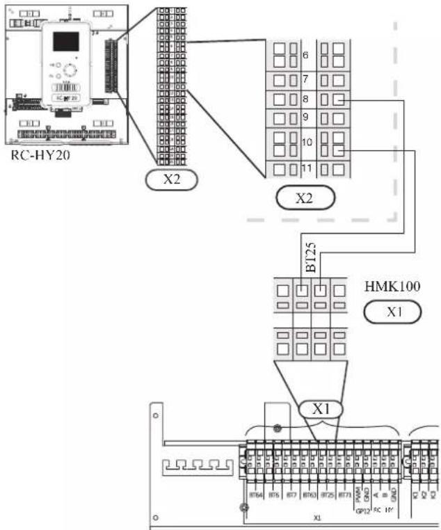
• Temperature sensor BT71, return pipe
The temperature sensor BT71 is placed on the return pipe line for water heater. For connection, see page 50, AUX inputs.
• Temperature sensor BT64, outlet for cooling
The temperature sensor BT64 is placed on the supply line for cooling. For connection, see page 51, AUX inputs.
- Ambient air temperature sensor BT1
Install ambient air temperature sensor (BT1) in the shade on a wall facing north or north-west, so it is unaffected by the morning sun for example.
Connect the sensor to the port 1 and 2 on X6 terminal on AA3 board.
If a conduit is used it must be sealed to prevent condensation in the sensor capsule.
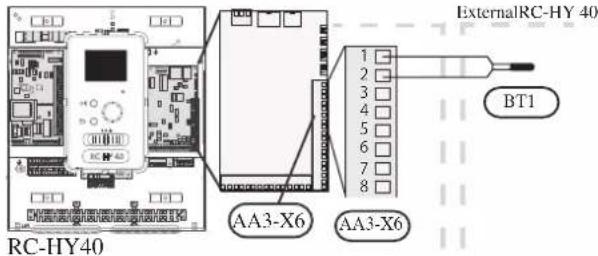
• Hot water charging sensor BT6 (tank bottom)
The temperature sensor, hot water charging (BT6) is placed in the submerged tube on the water heater.
Connect the sensor to the port 7 and 8 on X6 terminal on AA3 board.
Hot water charging is activated in menu 5.2 or in the start guide.

• Hot water sensor BT7 (tank top)
A temperature sensor for hot water top (BT7) can be connected to RC-HY40 to show the water temperature at the top of the tank (if it is possible to install a sensor at the top of the tank).
Connect the sensor to the port 15 and 16 on X6 terminal on AA3 board.
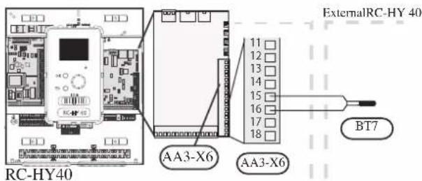
• Temperature sensor BT63, outlet at additional heater
This sensor is used in case electric heater is placed before 3 way valve (QN10) for switching heating/hotwater (see page 26 for diagram).
For connection, see page54, AUX inputs.
• Temperature sensor BT25, outlet for heating
This sensor is used in case electric heater is placed after 3 way valve (QN10) for switching heating/ hot water (see page 27 for diagram).
Connect temperature sensor, external supply line (BT25) to the port 5 and 6 on X6 terminal on AA3 board.

• Temperature sensor BT71, return line for heating
This sensor is used in case electric heater is placed after 3 way valve (QN10) for switching heating/ hot water (see page 27 for diagram).
Connect temperature sensor, external return line (BT71) to the port 17 and 18 on X6 terminal on AA3 board.
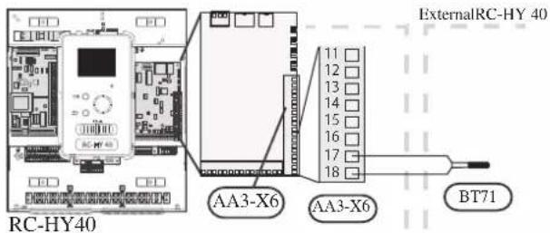
• Temperature sensor BT64, outlet for cooling
This sensor is used in case cooling application is required.
For connection, see page 54, AUX inputs.
- Ambient air temperature sensor BT1
Refer to the connection RC-HY40 with HSB100.
• Hot water charging sensor BT6 (tank bottom)
The temperature sensor, hot water charging (BT6) is placed at the bottom part of the water heater. Connect the port 7 and 8 on X6 terminal on AA3 board on RC-HY40 to the port BT6 on X1 terminal on HMK100.
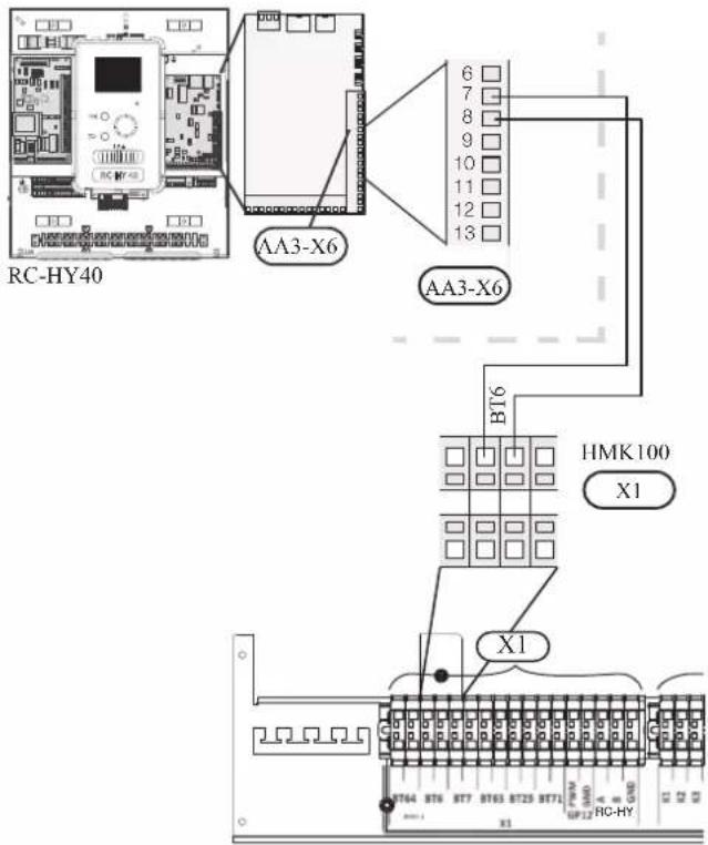
• Hot water sensor BT7 (tank top)
The temperature sensor, hot water top (BT7) is placed at the top of the water heater. Connect the port 15 and 16 on X6 terminal on AA3 board on RC-HY40 to the port BT7 on X1 terminal on HMK100.
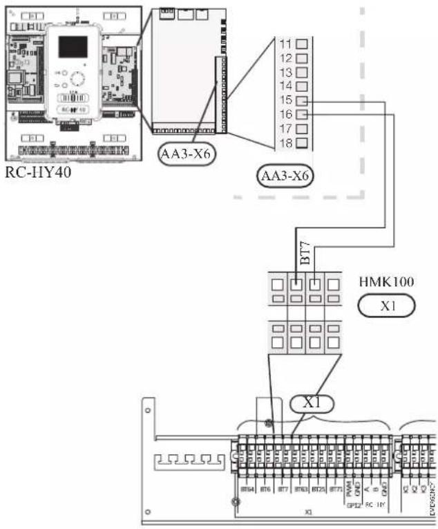
• Temperature sensor BT63, outlet at additional heater
The temperature sensor BT63 is placed on the outlet at additional heater. For connection, see page 54, AUX inputs.
• Temperature sensor BT25, outlet for heating
The temperature sensor BT 25 is placed on the supply line for heating. Connect the port 5 and 6 on X6 terminal on RC-HY40 to the port BT25 on X1 terminal on HMK100.
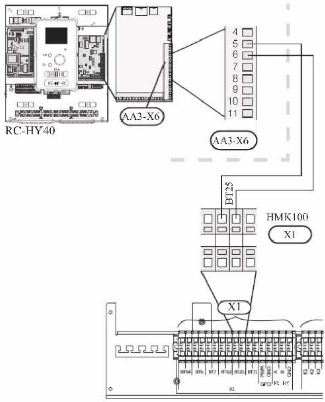
• Temperature sensor BT71, return pipe
The temperature sensor BT71 is placed on the return pipe line for water heater. Connect the port 17 and 18 on X6 terminal on AA3 board on RC-HY40 to the port BT71 on X1 terminal on HMK100.
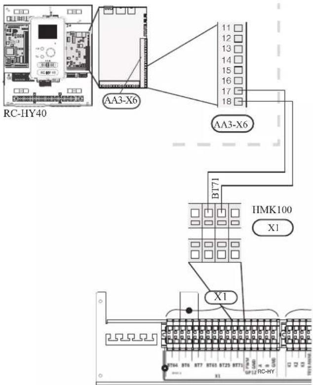
• Temperature sensor BT64, outlet for cooling
The temperature sensor BT64 is placed on the supply line for cooling. For connection, see page 54, AUX inputs.
Optional connections
RC-HY20
• Room sensor BT50
Room sensor can be connected to controller.
The room temperature sensor has up to three functions:
- Show current room temperature in the control module display.
- Option of changing the room temperature in °C.
- Makes it possible to change/stabilise the room temperature. Install the sensor in a neutral position where the set temperature is required. A suitable location is on a free inner wall in a hall approx. 1.5 m above the floor.
Do not install the sensor where correct room temperature cannot be detected such as in a recess, between shelves, behind a curtain, above or close to a heat source, in a draft from an external door or in direct sunlight.
Closed radiator thermostats can also cause problems.
The control module can operate without the sensor, but if user wants to read off the accommodation's indoor temperature in controller display, the sensor must be installed.
Connect the room sensor to the port 7 and 10 on X2 terminal.
If the sensor is to be used to change the room temperature in ^ C and/or to change/stabilise the room temperature, the sensor must be activated in menu 1.9.4.
If the room sensor is used in a room with underfloor heating, it should only have an indicative function, not control of the room temperature.
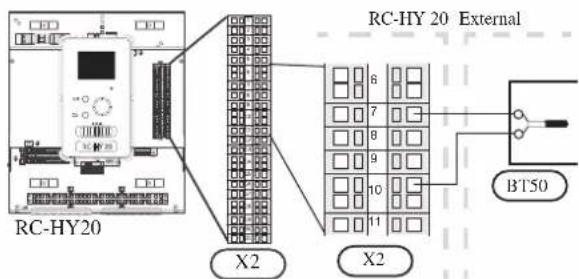
CAUTION
Changes of temperature in accommodation take time. For example, short time periods in combination with underfloor heating will not give a noticeable difference in room temperature.
Use two-core cable with a minimum 0.5mm^2 cross section.
- Step controlled additional heat
NOTE
Mark up any junction boxes with warnings for external voltage.
External step controlled additional heat can be controlled by up to three potential-free relays in the control module (3 step linear or 7 step binary). Alternatively two relays (2 step linear or 3 step binary) can be used for step controlled additional heat, which means that the third relay can be used to control the immersion heater in the water heater/accumulator tank.
Step in occurs with at least 1 minute intervals and step outs with at least 3 seconds intervals.
Step 1 is connected to terminal block X2:2 on the additional relay board (AA7).
Step 2 is connected to terminal block X2:4 on the additional relay board (AA7).
Step 3 or immersion heater in the water heater/accumulator tank is connected to terminal block X2:6 on the additional relay board (AA7).
The settings for step controlled additional heat are made in menu 4.9.3 and menu 5.1.12.
All additional heat can be blocked by connecting a potential-free switch function to the software controlled input on terminal block X2 which is selected in menu 5.4.
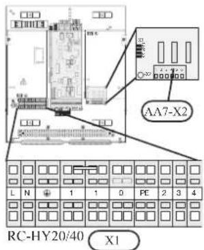
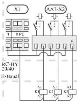
If the relays are to be used for control voltage, bridge the supply from terminal block X1:1 to X2:1, X2:3 and X2:5 on additional relay board (AA7). Connect the neutral from the external additional heat to terminal block X1:0.
Use a cable with appropriate cross section.
For connection, see the installation manual for additional heater.
Connect the port 2, 4, 6 on X2 terminal on AA7 board on RC-HY20/40 to the port K1, K2, K3 on X2 terminal on HMK100 respectively.
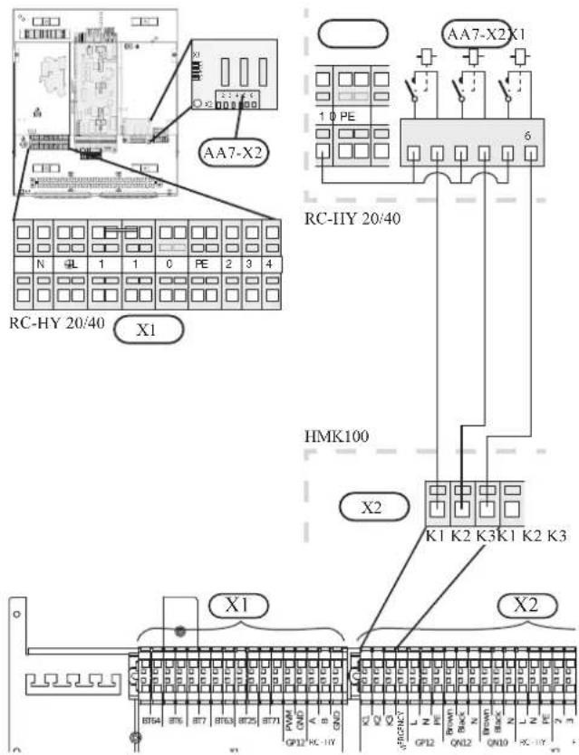
- Relay output for emergency mode
NOTE
Mark up any junction boxes with warnings for external voltage.
When the switch (SF1) is in " " mode (emergency mode) the circulation pump is activated (EB101-GP12).
CAUTION
No hot water is produced when emergency mode is activated.
The emergency mode relay can be used to activate external additional heat. Between the port 2 and 4 is closed during emergency mode. An external thermostat must be connected to the control circuit (port 4) to control the temperature. Ensure that the heating medium circulates through the external additional heating.
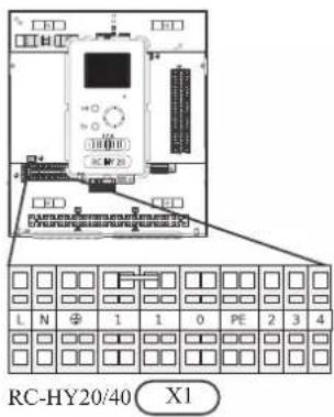
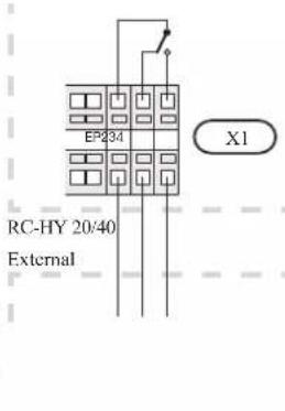
If the relay is to be used for control voltage, bridge the supply from terminal block X1:1 to X1:2 and connect neutral and control voltage from the external additional heat to X1:0 (N) and X1:4 (L).
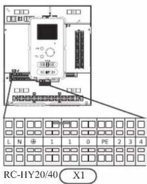
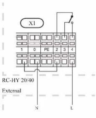
Connect the port 4 on X1 terminal on RC-HY20/40 to EMERGENCY on X2 terminal on HMK100, as well as the port 0 on X1 terminal on RC-HY20/40 to Neutral on HMK100.
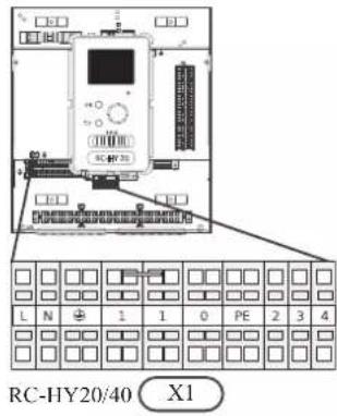
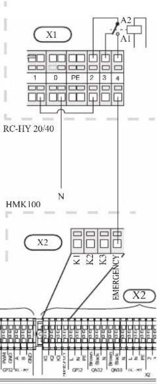
Set the supply temperature with the thermostat T1 in case of emergency mode. The setting range is 6-67°C. For floor heating, the setting must be min.20°C to max. 35-45°C in order to preserve heat comfort in the room and ensure effective system operation. When the temperature is set at 35°C or higher, be careful not to cause low temperature burn.
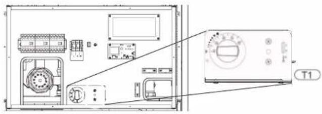
• External circulation pump
Connect the external circulation pump (GP10) to terminal block X4:9 (PE), X4:10 (N) and X4:11 (230 V) on the base board (AA2) as illustrated.
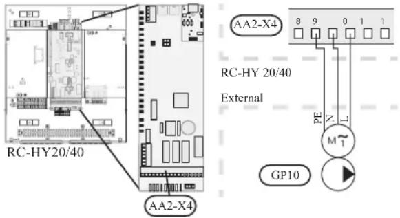
- AUX inputs
Other external inputs are available on the port 11 through 18 on X2 terminal on RC-HY20.
AUX1, 2, 3, 4, 5, and 6 correspond to the port 11, 12, 13, 15, 16 and 17 respectively. Port 14 and 18 are GND and are common to the all auxiliary circuit. Connect a sensor or switch between AUX and GND with a two-core cable with a minimum cross section of 0.5mm ^2 .

Select the appropriate function in menu 5.4.
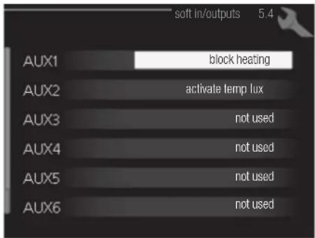
■ Temperature sensor, cooling/heating (BT74)
Additional room sensor (BT74) is applied in case user wants to determine the operation mode (cooling/heating) with a temperature in a particular room.
This option can be chosen only in case cooling function is available.
■ Temperature sensor, external return line (BT71)
Temperature sensor BT71 is applied in case additional heater is placed after 3-way valve (see page 27 and 28 for diagram).
■ Temperature sensor, flow line cooling (BT64)
Temperature sensor BT64 is required in case 4-pipe system is used for cooling operation. (see page 26-28 for diagram) This option can be chosen only in case cooling function is activated.
■ Contact for external tariff blocking
In cases where external tariff blocking is required it must be connected to terminal block X2.
Tariff blocking means that the additional heat, the compressor, heating and cooling are disconnected by connecting a potential free switch function to the input selected in menu 5.4.
A closed contact results in the electrical output being disconnected.
■ Switch for "SG ready"
NOTE
This function can only be used in mains networks that support the "SG Ready"-standard. "SG Ready" requires two AUX inputs.
This function can only be used in power supply networks that support the “SG Ready” standard. “SG Ready” requires two AUX inputs.
“SG Ready” is a smart tariff management scheme in which electricity supplier can affect indoor and hot water temperature or simply prohibits additional heat and/or the compressor operation in heat pump at certain period of the day. You can choose which operation mode is affected by this function in menu 4.1.5 after the function is activated.
Choose two external input circuits and connect potential-free switches, and set “SG Ready A” and “SG Ready B” in menu 5.4. The system works differently according to the combination of the circuit open/closed.
- Blocking (A: Closed, B: Open)
“SG Ready” is active. Compressor operation and additional heat is prohibited.
• Normal mode (A: Open, B: Open)
“SG Ready” is not active. No effect on the system.
- Low price mode (A: Open, B: Closed)
"SG Ready" is active. The system operates to provide higher capacity than normal mode by using lower tariff electricity. You can select the operation mode (heating/hot water/cooling) affected by this function in menu 4.1.5.
• Overcapacity mode (A: Closed, B: Closed)
“SG Ready” is active. The system supplies higher capacity than Low price mode since the electricity price is supposed to be very low in this mode. You can select the operation mode (heating/hot water/cooling) affected by this function in menu 4.1.5.
■Contact for activation of "temporary lux"
Temporary hot water production function “temporary lux” is activated with this signal. Connect the terminals with a potential-free switch and choose the function in menu 5.4.
"Temporary lux" is activated only when the switch is closed.
■Contact for activation of "external adjustment"
Target temperature offset for supply temperature or room temperature can be done with this signal.
When a room sensor is connected and activated, the target room temperature is offset in ^ C if the switch is closed. When a room sensor is not connected, target supply water temperature (heat curve) is offset instead. The degree of off set can be set in menu 5.4.
■Switch for external alarm
Alarms from external devices can be connected to the control and appear as an info alarm. Potential-free signal of NO or NC type can be connected.
■Switch for external blocking
This function is used in case certain operation mode needs to be prohibited. The operation at selected operation mode is prohibited when the switch is closed. Following functions can be managed.
• Additional heat
- compressor operation
- heating mode
- cooling mode
- hot water mode
- AUX outputs
External output is available on the port 15 to 17 on X4 terminal on AA2 board on RC-HY20. The relay output can have a max load of 2A at resistive load.

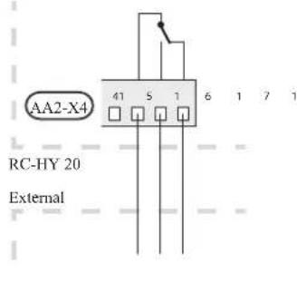
Following functions are available. Select the function in menu 5.4.
• Indication of buzzer alarm
When an alarm occurs, the circuit becomes closed between the port 15 and 16. During normal operation, the port 15 and 17 is closed.
- Cooling mode indication / Active cooling mode (4-pipe cooling)
When the system turns into cooling mode, the circuit becomes closed between the port 15 and 16. By using this signal, it is possible to switch 3-way valve for 4-pipe cooling or to assemble a display circuit indicating cooling mode. For details of connecting the 3-way valve, refer to page 40 to 41.
• External pump control (GP10)
External pump (GP10) is used in case additional heater is placed after 3-way valve that switches heating/hot water (refer to page 27 for diagram).
Connect the circulation pump as shown below using the port 15 and 16 on X4 terminal.
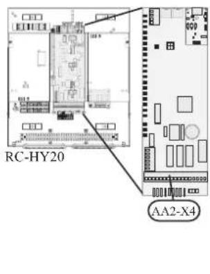
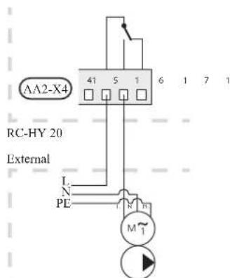
• Hot water circulation pump control (GP11)
In case the distance between hot water tap and hot water storage tank is far, the hot water supply line temperature is likely to drop and it may take time to supply hot water from the tap. In that case, hot water circulation pump (GP11) is applied to maintain hot water supply line temperature warm (refer to page 22 for diagram).
For details of connecting the pump, refer to External pump control (GP10).
NOTE
Mark up any junction boxes with warnings for external voltage.
- myUpway™
Connect the network connected cable (straight, Cat.5e UTP) with RJ45-contact (male) to contact AA4-X9 on the display unit (as illustrated). Use the cable grommet (UB2) in the control module for cable routing.
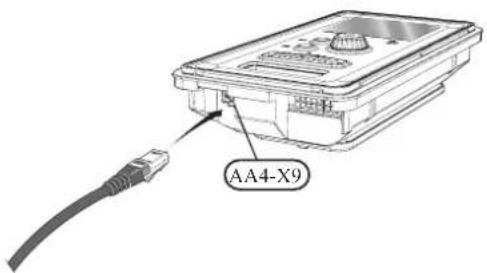
RC-HY40
- Load monitor
In case many power electrical appliances are connected in the property and the electric heater is energised at the same time, there is a risk of tripping the main fuse of the property.
The control module has an integrated load monitor that controls the power steps of the electric heater by disconnecting step by step in the event of overload in a phase. It will be reconnected if other current consumption is reduced.
Connecting current sensors
A current sensor (BE1 - BE3) should be installed on each incoming phase conductor in to the electrical distribution unit to measure the current. This is best done in the electrical distribution unit.
Connect the current sensors to a multi-core cable in an enclosure next to the electrical distribution unit. Use a multi-core cable of at least 0.5 mm ^2 from the enclosure to the heat pump.
Connect the cable to terminal block X4:1 to 4.
X4:1 is the common terminal block for the three current sensors.
Set the size of the property's main fuse in menu 5.1.12.
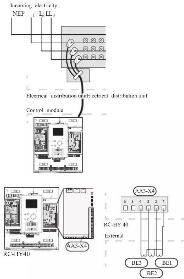
• Room sensor BT50
Refer to Room sensor BT50 for RC-HY20 for function and installation place.
Connect the room sensor to terminal block X6:3 and X6:4 on the input board (AA3).
If the sensor is to be used to change the room temperature in ^ C and/or to change/stabilise the room temperature, the sensor must be activated in menu 1.9.4.
If the room sensor is used in a room with underfloor heating, it should only have an indicative function, not control of the room temperature.

CAUTION
Changes of temperature in accommodation take time. For example, short time periods in combination with underfloor heating will not give a noticeable difference in room temperature.
- Step controlled additional heat
Refer to the explanation for RC-HY20. - Relay output for emergency mode
Refer to the explanation for RC-HY20.
• External circulation pump
Refer to the explanation for RC-HY20.
- AUX inputs
Up to 6 other external inputs are available on RC-HY40.
AUX1 through 3 correspond to the port 9/10, 11/12, 13/14 respectively on X6 terminal on AA3 board. AUX4 through 6 correspond to the port 1, 2 and 3 on X2 terminal on RC-HY40. Port 4 on X2 terminal is GND and is common to AUX4 through 6. Connect a sensor or switch between AUX and GND with a two-core cable with a minimum cross section of 0.5mm ^2 .

Select the appropriate function in menu 5.4.
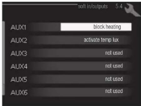
■ Temperature sensor, external supply at additional heat before reversing valve (BT63) Temperature sensor BT63 is applied in case additional heater is placed before 3-way valve (see page 26 for diagram)
The following functions are available. For details, see AUX inputs for RC-HY20.
■ Temperature sensor, cooling/heating (BT74)
■ Temperature sensor, external return line (BT71)
■ Temperature sensor, flow line cooling (BT64)
■ Contact for external tariff blocking
■ Switch for "SG ready"
■Contact for activation of "temporary lux"
■Contact for activation of "external adjustment"
■Switch for external alarm
■Switch for external blocking
- AUX outputs
External output is available on the port NC, NO and C on X7 terminal on AA3 board on RC-HY40. The relay output can have a max load of 2A at resistive load.

Following functions are available. Select the function in menu 5.4.
• Indication of buzzer alarm
When an alarm occurs, the circuit becomes closed between the port NO and C. During normal operation, the port NC and C is closed.
• Cooling mode indication / Active cooling mode (4-pipe cooling)
When the system turns into cooling mode, the circuit becomes closed between the port NO and C. By using this signal, it is possible to switch 3-way valve for 4-pipe cooling or to assemble a display circuit indicating cooling mode. For details of connecting the 3-way valve, refer to page 40 and 41.
• External pump control (GP10)
External pump (GP10) is used in case additional heater is placed after 3-way valve that switches heating/hot water (refer to page 27 and 28 for diagram).
Connect the circulation pump using the port NO and C on X7 terminal on AA3 board as shown below.
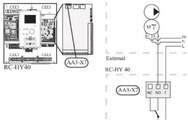
• Hot water circulation pump control (GP11)
In case the distance between hot water tap and hot water storage tank is far, the hot water supply line temperature is likely to drop and it may take time to supply hot water from the tap. In that case, hot water circulation pump (GP11) is applied to maintain hot water supply line temperature warm (refer to page 22 for diagram).
For details of connecting the pump, refer to External pump control (GP10).
NOTE
Mark up any junction boxes with warnings for external voltage.
- myUpway™
Connect the network connected cable (straight, Cat.5e UTP) with RJ45-contact (male) to contact AA4-X9 on the display unit (as illustrated). Use the cable grommet (UB2) in the control module for cable routing.
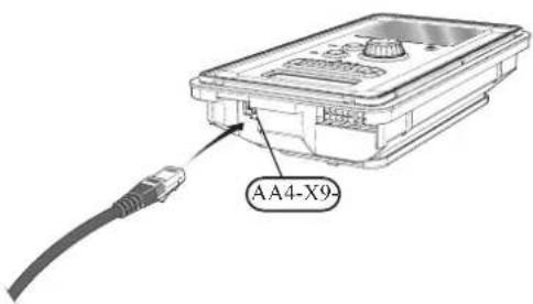
Commissioning and adjusting Preparations
Before starting commissioning, check the followings;
- The signal cable is connected between indoor unit and outdoor unit as well as indoor unit and controller according to the instruction.
- The power cable is connected to indoor unit, outdoor unit and controller according to the instruction.
- Operation switch in controller is in the position ⏻.
- The service valves on outdoor unit (QM35 and QM36) are open.
- Drain valve is closed before filling water in the system.
• Temperature limiter and electrical switch are not tripped. - The system is filled with water and well vented.
• There are no leaks on the water pipe.
Filling and venting
Hot water tank
- Open the hot water tap as well as venting valve if applicable, and then open the cold water cut-off valve at the inlet.
- Fill the storage tank until obtaining uniform water outflow at the hot water tap, and then close the hot water tap and venting valve.
- Fill the water heater coil in the tank. See Climate system for details.
After the installation and levelling the tank, follow the procedure below (for the connector pipe symbols, refer to page 18):
- Remove protecting plugs from the connector pipes
- Connect the hot water intake line (N).
- Connect the cold water supply line together with the required safety valves (G).
- If the system has the hot water circulati on system, connect it to the connector pipe (L). Otherwise, plug the pipe.
- Connect the supply (J) and return (H) of the heating medium to the coil.
CAUTION
If there is an electric heating module installed in the storage tank, fill the tank with water before connecting it to the electrical installation.
CAUTION
Open the hot water intake valves before heating the system up for the first time or after a longer break in its operation in order to check whether the storage tank is filled with water and the cut-off valve at the cold water inlet is not closed.
Climate system
- Open the vent at the top of the heating system.
- Open all shut-off valves, where installed, so that water flows into all circuits.
- Open the valve for filling the heating circuit and fill it with water.
- Close the vent when water comes out continuously without bubbles.
- Check the manometer and close the fllling valve when the pressure reaches the required value (2 bar is recommended).
- Start the circulation pump of the heating system, and open the vent from time to time and release the all remaining air in the heating system.
- Open safety valve until the pressure of the heating system drops down to about 1 bar. If the pressure drops below 1 bar during venting, add additional water in the circuit.
Inspection of installation
Current regulations require that the climate system is inspected before it is commissioned. The inspection must be carried out by a suitably qualified person and must be documented. Do not replace any part of the system without carrying out new checks.
Start-up and inspection
Before start-up
1 In case of cascade connection, check if each indoor unit has a unique address. See Cascade connection setting on page 35 for details.
2. For an outdoor unit equipped with a crank case heater, it is necessary to supply power 6-8 hours before starting compressor operation to heat the compressor with the heater. To do this, supply power to whole system and disable the compressor operation from menu 5.2.2 on the controller. Disable additional heater as well if necessary.
3. After 6-8 hours, enable the compressor operation in menu 5.2.2 on the controller and enable the additional heater in menu 4.9.2 and 4.9.3 on the controller.
4. Start commissioning by the following steps.
*Step 2 and 3 are not necessary for FDCW60VNX-A.
Commissioning with heat pump
Start guide is shown on the display on the controller when it is turned ON for the first time. Follow the start guide in the display, or choose menu 5.7 to show the start guide. For details, see Start guide on page 58.
Commissioning with additional heater only
Follow the start guide in the display as same as commissioning with heat pump, and then follow the list below.
- Go to menu 4.2 op. mode.
- Mark "add. heat only" using the control knob and then press the OK button.
- Return to the main menus by pressing the Back button.
CAUTION
When commissioning without MHI air /water heat pump an alarm communication error may appear in the display. The alarm is reset if the relevant heat pump is deactivated in menu 5.2.2 ("installed heat pump").
3-way valve operation check
- Activate "AA2-K1 (QN10)" in menu 5.6.
- Check that the reversing valve opens or is open for hot water charging.
- Deactivate "AA2-K1 (QN10)" in menu 5.6.
AUX function check
To check any function connected to the AUX socket,
- Activate "AA2-X4 (RC-HY20)" or "AA3-X7 (RC-HY40)" in menu 5.6.
- Check the desired function.
- Deactivate "AA2-X4 (RC-HY20)" or "AA3-X7 (RC-HY40)" in menu 5.6.
Cooling mode
In case the climate system contains a cooling circuit, activate cooling function in menu 5.11.1.1. After that, you can choose cooling mode indication in menu 5.4 for the AUX output.
Cleaning particle filter
Clean the particle filter (HQ1) after installation.
- Close valve QM31 and the valve by the particle filter (HQ1).
- Open the safety valve (QM20) to ensure that the pressure in HSB60 drops.
- Clean the particle filter (HQ1) as illustrated.


Secondary adjustment
Air is initially released from the hot water and venting may be necessary. If bubbling sounds can be heard from the heat pump, the circulation pump and radiators the entire system will require further venting. When the system is stable (correct pressure and all air eliminated) the automatic heating control system can be set as required
Start guide
NOTE
Fill in the climate system with water before the switch is set to " | "
- Set the control module's switch to "|".
- Follow the instructions in the start guide in the control module display. If the start guide does not start when you start the control module, start it manually in menu 5.7.
TIP
See page 63 for a more in-depth introduction to the installation's control system (operation, menus etc.).
Commissioning
The start guide is displayed when installation is started, It describes what needs to carry out at the first start together with basic settings during installation.
The start guide is displayed so that it cannot be bypassed in order to carry out the start-up correctly. You can start the start guide later in menu 5.7.
During the start-up guide, reversing valves and the shunt are run back and forth to help vent the heat pump.
CAUTION
As long as the start guide is active, no function in the heat pump will start automatically.
Each time the controller is ON, the guide will appear until it is completed on the last page.
Operation in the start guide
A. Page
B.Name and menu number

C.Option / setting
A. Page
You can see the current page of the start guide.
Scroll between the pages of the start guide as follows:
- Turn the control knob until the arrow is marked in the top left corner (at the page number).
- Press OK button to proceed to the next page in the start guide.
B. Name and menu number
You can see the menu name of this page. The number refers to the menu number in the control system.
To read more about affected menus, see the help menu or read the user manual.
C. Option / setting
Make settings for the system here.
D. Help menu

In many menus there is a symbol indicating that extra help is available.
To access the help text:
- Use the control knob to select the help symbol.
- Press OK button.
The help text often consists of several windows that you can scroll between using the control knob.
Heating/cooling curve setting

line
| outdoor temp. °C | flow temperature °C | |---|---| | -40 | 60 | | -30 | 55 | | -20 | 50 | | -10 | 45 | | 0 | 40 | | 10 | 35 | | 20 | 20 | | 30 | 15 | | 40 | 10 |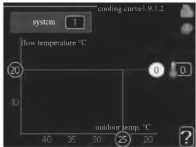
heating curve
Setting range: 0 - 15
Default value: 9
cooling curve (accessory required)
Setting range: 0 - 9
Default value: 0
The prescribed heating curve for your house can be viewed in the menu heating curve. The task of the heating curve is to give an even indoor temperature, regardless of the outdoor temperature, and thereby energy efficient operation. From this heating curve, the control module determines the temperature of the water to the heating system, supply temperature, and there by the indoor temperature. Select the heating curve and read off how the supply temperature changes at different outdoor temperatures here. If there is cooling function, the same settings can be made for the cooling curve.
Curve coefficient
The heating/cooling curve shows the relation between the target supply temperature and the corresponding outdoor temperature. A steep curve indicates that supply temperature becomes higher at low outdoor air temperature in heating and it becomes lower at high outdoor air temperature in cooling.
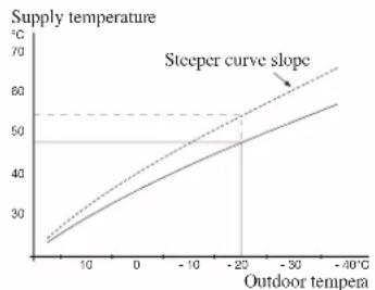
line
| Outdoor tempera | Supply temperature (°C) | | --------------- | ------------------------ | | 0 | 25 | | 10 | 35 | | 20 | 45 | | 30 | 55 | | -40 | 65 |The optimum slope depends on the climate conditions in your location, the type of heating device (radiators or under floor heating) and how well insulated the house is.
The curve is set when the heating installation is installed, but may need adjusting later. Normally, the curve will not need further adjustment.
CAUTION
In the event of making fine adjustments of the indoor temperature, the curve must be offset up or down instead, this is done in menu 1.1 temperature.
Curve offset
The target temperature can be off set in parallel over the entire outdoor temperature range by this function. This is offset by 5 °C by adjusting 2 steps.
The target temperature can be parallel offset in the entire outdoor temperature range with this function. It is offset by 5 °C by adjusting 2 steps.

line
| Outdoor temperature (°C) | Supply temperature (°C) | | ------------------------ | ----------------------- | | 0 | 25 | | 10 | 35 | | 20 | 45 | | -20 | 50 | | -30 | 55 | | -40 | 60 |Flow line temperature – maximum and minimum values
This function is used in order to limit max-min supply temperature. The heating / cooling curve becomes fl at beyond max / min target temperature.
CAUTION
Underfloor heating systems are normally max flow line temperature set between 35 and 45°C. Take care not to cause low temperature burns in case it is set higher than 35°C.
Must be restricted with underfloor cooling min. flow line temp. to prevent condensation.
Check the max temperature for your floor with your installer/floor supplier.
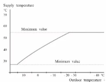
line
| Outdoor temperature (°C) | Supply temperature (°C) | |---|---| | 0 | 28 | | 10 | 35 | | 20 | 40 | | -10 | 45 | | -20 | 50 | | -30 | 55 | | -40 | 55 | The chart includes a dashed horizontal line labeled 'Maximum value' at approximately 55 and 'Minimum value' at approximately 28. The x-axis is labeled 'Outdoor temperature' and the y-axis is labeled 'Supply temperature'. The curve shows a steady increase in supply temperature as outdoor temperature rises from 0 to -20, followed by a plateau at maximum value for temperatures above -20.The figure at the end of the curve indicates the curve number. The figure beside the thermometer icon gives the curve off set. Use the control knob to set a new value.
Confir rm the new setting by pressing the OK button.
Curve 0 is an own curve created in menu 1.9.7.
To select another curve (slope):
- Press OK button to access the setting mode
-
Select a new curve. The curves are numbered from 0 to 15, and the bigger number curve has steeper slope.
Curve 0 means that own curve (menu 1.9.7) is used. -
Press OK button to exit the setting.
To read off a curve:
- Turn the control knob so that the ring on the shaft with the outdoor temperature is marked.
- Press OK button.
- Follow the grey line up to the curve and out to the left to read off the value for the supply temperature at the selected outdoor temperature.
- You can now select to take read outs for different outdoor temperatures by turning the control knob to the right or left and read off the corresponding flow temperature.
- Press OK or Back button to exit read off mode.
TIP
Wait 24 hours before making a new setting, so that the room temperature has time to stabilise.
If it is cold outdoors and the room temperature is too low, increase the curve slope by one increment.
If it is cold outdoors and the room temperature is too high, lower the curve slope by one increment.
If it is warm outdoors and the room temperature is too low, increase the curve offset by one increment.
If it is warm outdoors and the room temperature is too high, lower the curve offset by one increment.
Hot water circulation setting
hot water recirc.
operating time
Setting range: 1 - 60 min
Default value: 60 min
downtime
Setting range: 0 – 60 min
Default value: 0 min
Set the hot water circulation for up to three periods per day here. During the set periods the hot water circulation pump will run according to the settings above.
"operating time" decide how long the hot water circulation pump must run per operating instance.
"downtime" decide how long the hot water circulation pump must be stationary between operating instances.
Hot water circulation is activated in menu 5.4 "soft inputs and outputs".
SG Ready
This function can only be used in mains networks that support the "SG Ready"-standard.
Make settings for the function "SG Ready" here.
Low price mode means that the electricity supplier has a low tariff and the system uses this to reduce costs.
Over capacity mode means that the electricity supplier has set the tariff very low and the system uses this to reduce the costs as much as possible.
affect room temperature
Here you set whether room temperature should be affected when activating "SG Ready".
With low price mode of "SG Ready" the parallel off set of the indoor temperature is increased by "+1". If a room sensor is installed and activated, the desired room temperature increases by 1 °C.
With over capacity mode of "SG Ready" the parallel off set for the indoor temperature is increased by "+2".
If a room sensor is installed and activated, the desired room temperature increases by 2 °C.
affect hot water
Here you set whether the temperature of the hot water should be affected when activating "SG Ready".
With low price mode on "SG Ready" the stop temperature of the hot water is set as high as possible at only compressor operation (immersion heater not permitted).
With over capacity mode of "SG Ready" the hot water is set to "luxury" (immersion heater permitted).
affect cooling (accessory required)
Here you set whether room temperature during cooling operation should be affected when activating "SG Ready".
With low price mode of "SG Ready" and cooling operation the indoor temperature is not affected.
With over capacity mode of "SG Ready" and cooling operation the parallel off set for the indoor temperature is reduced by"-1". If a room sensor is installed and activated, the desired room temperature decreases by 1 °C.
NOTE
The function must be connected to two AUX inputs and activated in menu 5.4.
Control Display unit

A Display
Instructions, settings and operational information are shown on the display. The easy-to-read display and menu system, make it easy to navigate between various menus and options, set comfort and get the necessary information.
B Status lamp
The status lamp indicates the status of the control module. It:
■ lights green during normal operation.
■ lights yellow in emergency mode.
■ lights red in the event of an alarm.
C OK button
The OK button is used to:
■ confirm selections of sub menus/options/set values/page in the start guide.
D Back button
The back button is used to:
■ go back to the previous menu.
■ change a setting that has not been confirmed.
E Control knob
The control knob can be turned to the right or left. You can:
■ scroll in menus and between options.
■ increase and decrease values.
■ change pages in multiple page instructions (for example help text and service info).
F Switch (SF1)
The switch shows three positions:
■ On ( | )
■ Standby ( ⏻ )
■ Emergency mode ( △ )
Emergency mode must only be used in the event of a fault on the control module. In this mode, the compressor in the heat pump is turned off and the immersion heater is activated.
The control module display is not illuminated and the status lamp lights yellow.
G USB port
The USB port is hidden behind the plastic badge of the product name.
The USB port is used to update the software.
Menu system

Menu 1 - INDOOR CLIMATE
Setting and scheduling the indoor climate. See information in the help menu or user manual.
Menu 2 - HOT WATER
Setting and scheduling hot water production. See information in the help menu or user manual.
This menu only appears if a water heater is installed in the system.
Menu 3 - INFO
Display of temperature and other operating information and access to the alarm log. See information in the help menu or user manual.
Menu 4 - MY INSTALLATION
Setting time, date, language, display, operating mode etc. See information in the help menu or user manual.
Menu 5 - SERVICE
Advanced settings. These settings are not available to the end user. The menu is made visible by pressing the Back button for 7 seconds in the top screen. See page 68 for details.
Symbols in the display
The following symbols can appear in the display during operation.
| Symbol Description | |
| This symbol appears when there is information to be noticed in menu 3.1. |
| These two symbols indicate whether the compressor in the outdoor unit or additional heat in the installation is blocked via controller.These functions will be blocked for example, when either of the operation mode is blocked in menu 4.2, when blocking of either function is scheduled in menu 4.9.5, or when an alarm for blocking the operation occurs.Blocking the compressor.Blocking additional heat. |
| This symbol appears if periodic increase or lux mode for the hot water is activated. |
| This symbol indicates if "holiday setting" is active in menu 4.7. |
| This symbol indicates if the controller has contact with myUpway. |
 | This symbol indicates if cooling is active. |
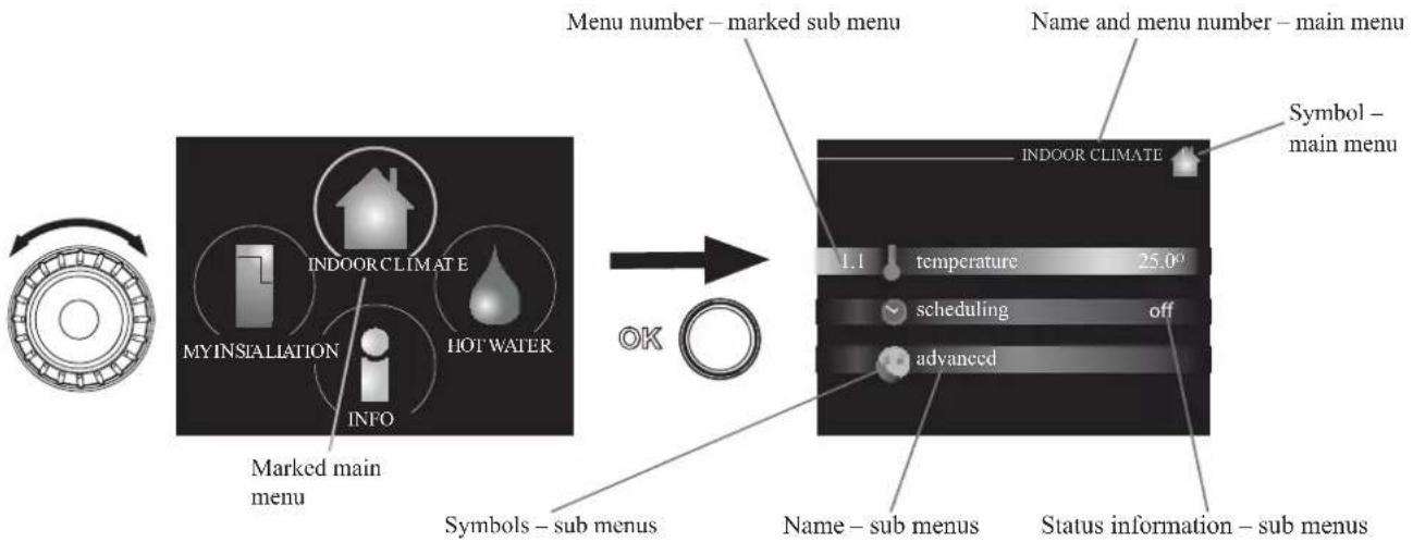
flowchart
graph LR
    A["Menu number – marked sub menu"] --> B["Symbol – main menu"]
    B --> C["INDOOR CLIMATE"]
    C --> D["temperature 25.0°"]
    C --> E["scheduling off"]
    C --> F["advanced"]
    D --> G["Symbols – sub menus"]
    E --> H["Marked main menu"]
    F --> I["My INSTALLATION INFO"]
    G --> J["Hot Water"]
    H --> K["OK"]
Operation
To move the cursor, turn the control knob to the left or the right. The marked position is brighter and/or has a light frame.

Selecting menu
To advance in the menu system select a main menu by marking it and then pressing the OK button. A new window opens with sub menus.
Select one of the sub menus by marking it and then pressing the OK button.
Selecting options

Alternative
In an options menu the current selected option is indicated by a green tick.

To select another option:
- Mark the applicable option. One of the options is pre-selected (white).

- Press the OK button to confirm the selected option. The selected option has a green tick.

Setting a value

Values to be changed
To set a value:
- Mark the value you want to set using the control knob.

- Press the OK button. The background of the value becomes green, which means that you have accessed the setting mode.

- Turn the control knob to the right to increase the value and to the left to reduce the value.

- Press the OK button to confirm the value you have set. To change and return to the original value, press the Back button.

Use the virtual keyboard

In some menus where text may require entering, a virtual keyboard is available.

Depending on the menu, you can gain access to different character sets which you can select using the control knob. To change character table, press the Back button. If a menu only has one character set, the keyboard is displayed directly.
When you have finished writing, mark "OK" and press the OK button.
Scroll through the windows
A menu can consist of several windows. Turn the control knob to scroll between the windows.

Scroll through the windows in the start guide

- Turn the control knob until one of the arrows in the top left corner (at the page number) has been marked.
- Press the OK button to skip between the steps in the start guide.
Help menu
In many menus there is a symbol that indicates that extra help is available.
To access the help text:
- Use the control knob to select the help symbol.
- Press the OK button.
The help text often consists of several windows that you can scroll between using the control knob.
Menu list
"* Accessories are needed. ** Heat pump with cooling function required. 40"
| MENU RC-HY20 RC-HY40 | ||||
| 1 INDOOR CLIMATE | ||||
| 1.1 - temperature 1.1.1 heating | ✓ | ✓ | ||
| 1.1.2 cooling ** | ✓ | ✓ | ||
| 1.3 - scheduling 1.3.1 heating | ✓ | ✓ | ||
| 1.3.2 cooling ** | ✓ | ✓ | ||
| 1.9 - advanced 1.9.1 curve 1.9.1.1 | heating curve | ✓ | ✓ | |
| 1.9.1.2 cooling curve ** | ✓ | ✓ | ||
| 1.9.2 external adjustment | ✓ | ✓ | ||
| 1.9.3 min. flow line temp. 1.9.3 | 1 heating | ✓ | ✓ | |
| 1.9.3.2 cooling ** | ✓ | ✓ | ||
| 1.9.4 room sensor settings | ✓ | ✓ | ||
| 1.9.5 cooling settings * | ✓ | ✓ | ||
| 1.9.7 own curve 1.9.7.1 heating | ✓ | ✓ | ||
| 1.9.7.2 cooling ** | ✓ | ✓ | ||
| 1.9.8 point off set | ✓ | ✓ | ||
| 2 HOTWATER | ||||
| 2.1 temporary lux | ✓ | ✓ | ||
| 2.2 comfort mode | ✓ | ✓ | ||
| 2.3 scheduling | ✓ | ✓ | ||
| 2.9 advanced 2.9.1 periodic increase | ✓ | ✓ | ||
| 2.9.2 hot water recirc. * | ✓ | ✓ | ||
| 3 INFO | ||||
| 3.1 service info | ✓ | ✓ | ||
| 3.2 compressor info | ✓ | ✓ | ||
| 3.3 add. heat info | ✓ | ✓ | ||
| 3.4 alarm log | ✓ | ✓ | ||
| 3.5 indoor temp. log | ✓ | ✓ | ||
| 4. MY SYSTEM | ||||
| 4.1 plus functions 4.1.3 internet 4.1.3.1 myUpwayTM | ✓ | ✓ | ||
| 4.1.3.8 tcp/ip settings | ✓ | ✓ | ||
| 4.1.3.9 proxy settings | ✓ | ✓ | ||
| 4.1.5 SG Ready | ✓ | ✓ | ||
| 4.1.6 smart price adaptionTM | ✓ | ✓ | ||
| 4.1.8 smart energy sourceTM | 4.1.8.1 settings | - | ||
| 4.1.8.2 set. Price | - | |||
| 4.1.8.3 CO2 impact | - | |||
| 4.1.8.4 tariff periods, electricity | - | |||
| 4.1.8.6 tariff per, ext. shunt add | - | |||
| 4.1.8.7 tariff per, ext. step add | - | |||
| 4.2 op. mode | ✓ | ✓ | ||
| 4.3 my icons | ✓ | ✓ | ||
| 4.4 time & date | ✓ | ✓ | ||
"* Accessories are needed. ** Heat pump with cooling function required. 40"
| MENU RC-HY20 RC-HY40 | ||||
| 4.6 language | ✓ | ✓ | ||
| 4.7 holiday setting | ✓ | ✓ | ||
| 4.9 advanced 4.9.1 op. prioritisation | ✓ | ✓ | ||
| 4.9.2 auto mode setting | ✓ | ✓ | ||
| 4.9.3 degree minute setting | ✓ | ✓ | ||
| 4.9.4 factory setting user | ✓ | ✓ | ||
| 4.9.5 schedule blocking | ✓ | ✓ | ||
| 4.9.6 schedule silent mode | ✓ | ✓ | ||
| 5 SERVICE | ||||
| 5.1 operating settings 5.1.1 hot water settings * | ✓ | ✓ | ||
| 5.1.2 max flow line temperature | ✓ | |||
| 5.1.3 max diff flow line temp. | ✓ | |||
| 5.1.4 alarm actions | ✓ | |||
| 5.1.12 addition | ✓ | |||
| 5.1.14 flow set climate system | ✓ | |||
| 5.1.22 heat pump testing | ✓ | |||
| 5.1.23 compressor curve | ✓ | |||
| 5.2 system settings 5.2.2 installed slaves | ✓ | ✓ | ||
| 5.2.3 docking | ✓ | |||
| ✓ | ||||
| 5.2.4 accessories | controlled add. heat * | - | ||
| 5.3.3 extra climate system * | - | |||
| 5.3.6 step controlled add. Heat | - | |||
| 5.3.8 hot water comfort * | - | |||
| 5.3.20 flow sensor* | - | |||
| 5.4 soft in/outputs | ✓ | ✓ | ||
| 5.5 factory setting service | ✓ | ✓ | ||
| 5.6 forced control | ✓ | ✓ | ||
| 5.7 start guide | ✓ | ✓ | ||
| 5.8 quick start | ✓ | ✓ | ||
| 5.9 floor drying function | ✓ | ✓ | ||
| 5.10 change log | ✓ | ✓ | ||
| 5.11 slave settings 5.11.1 EB101 | 5.11.1.1 heat pump | ✓ | ✓ | |
| 5.11.1.2 charge pump (GP12) | ✓ | ✓ | ||
| 5.11.2 EB102 | - | ✓ | ||
| 5.11.3 EB103 | - | ✓ | ||
| 5.11.4 EB104 | - | ✓ | ||
| 5.11.5 EB105 | - | ✓ | ||
| 5.11.6 EB106 | - | ✓ | ||
| 5.11.7 EB107 | - | ✓ | ||
| 5.11.8 EB108 | - | ✓ | ||
| 5.12 country | ✓ | ✓ | ||
Sub-menus
Menu SERVICE has orange text and is intended for the advanced user. This menu has several sub-menus.
Status information for the relevant menu can be found on the display to the right of the menus.
operating settings: Operating settings for the control module.
system settings: System settings for the control module, activating accessories etc.
soft in/outputs: Setting software controlled in and outputs on the input card (AA3) and terminal block (X2).
factory setting service: Total reset of all settings (including settings available to the user) to default values.
forced control: Forced control of the different components in the indoor module.
start guide: Manual start of the start guide which is run the first time when the control module is started.
quick start: Quick starting the compressor.
NOTE
Incorrect settings in the service menus can damage the installation.
Menu 5.1 - operating settings
Operating settings can be made for the control module in the sub menus.
Menu 5.1.1 - hot water settings
economy
Setting range start temp. economy: 5 - 55 °C
Factory setting start temp. economy: 42 °C
Setting range stop temp. economy: 5 - 60 °C
Factory setting stop temp. economy: 48 °C
normal
Setting range start temp. normal: 5 - 60 °C
Factory setting start temp. normal: 46 °C
Setting range stop temp. normal: 5 - 65 °C
Factory setting stop temp. normal: 50 °C
luxury
Setting range start temp. lux: 5 - 70 °C
Factory setting start temp. lux: 49 °C
Setting range stop temp. lux: 5 - 70 °C
Factory setting stop temp. lux: 53 °C
stop temp. per. increase
Setting range: 55 – 70 °C
Factory setting: 55 °C
charge method
Setting range: target temp, delta temp
Default value: delta temp
Here you set the start and stop temperature of the hot water for the different comfort options in menu 2.2 as well as the stop temperature for periodic increase in menu 2.9.1.
The charge method for hot water mode is selected here. "delta temp" is recommended for heaters with charge coil, "target temp" for heaters with domestic coil.
Menu 5.1.2 - max flow line temperature
climate system
Setting range: 5 - 70 °C
Default value: 60 °C
Set the maximum supply temperature for the climate system here. If the installation has more than one climate system, individual maximum supply temperatures can be set for each system. Climate systems 2 – 8 cannot be set to a higher max supply temperature than climate system 1.
CAUTION
Underfloor heating systems are normally max flow line temperature set between 35 and 45°C.
Be careful not to cause low temperature burn if it is set at 35^ C or higher.
Check the max floor temperature with your floor supplier.
Menu 5.1.3 - max diff flow line temp.
max diff compressor
Setting range: 1 – 25 °C
Default value: 10 °C
max diff addition
Setting range: 1 - 24 °C
Default value: 7 °C
Here you set the maximum permitted difference between the calculated and actual supply temperature during compressor mode and add. heat mode. Max diff. additional heat can never exceed max diff. compressor
max diff compressor
When the current supply temperature deviates from the set value compared to that calculated, the heat pump is forced to stop irrespective of the degreeminate value.
If the current supply temperature exceeds the calculated flow temperature plus the set value, the degree minute value is set to 0. The compressor in the heat pump stops when there is only a heating demand.
max diff addition
If "addition" is selected and activated in menu 4.2 and the present supply temp exceeds the calculated temperature plus the set value, the additional heat is forced to stop.
Menu 5.1.4 - alarm actions
Select how to control the heat pump in the event of an alarm. You can choose to stop producing hot water and/or reduce the room temperature.
CAUTION
If no alarm action is selected, it can result in higher energy consumption in the event of an alarm.
Menu 5.1.12 - addition
add type: step controlled
max step
Setting range (binary stepping deactivated): 0 - 3
Setting range (binary stepping activated): 0 - 7
Default value: 3
fuse size
Setting range: 1 - 200 A
Factory setting: 16 A
You can set the maximum number of permitted additional heat steps, if there is internal additional heat in the tank (only accessible if the additional heat is positioned after QN10), whether binary stepping is to be used and the size of the fuse.
prioritised additional heat
Setting range: on/off
Factory setting: off
minimum running time
Setting range: 0 – 48 h
Default value: 12 h
min temp.
Setting range: 5 – 90 °C
Default value: 55 °C
mixing valve amplifier
Setting range: 0.1 - 10.0
Default value: 1.0
mixing valve step delay
Setting range: 10 - 300 s
Default values: 30 s
fuse size
Setting range: 1 - 200 A
Factory setting: 16 A
transformation ratio
Setting range: 300 - 3000
Factory setting: 300
Select this option if shunt controlled additional heat is connected.
Set when the addition is to start, the minimum run time and the minimum temperature for external addition with shunt here. External addition with shunt is for example a wood/oil/gas/pellet boiler.
You can set shunt valve amplification and shunt valve waiting time.
Selecting "prioritised additional heat" uses the heat from the external additional heat instead of the heat pump.
The shunt valve is regulated as long as heat is available, otherwise the shunt valve is closed.
TIP
See the accessory installation instructions for function description.
Menu 5.1.14 - flow set. climate system
presettings
Setting range: radiator, fl oor heat., rad. + fl oor heat.
Default value: radiator
Setting range DOT: -40.0 – 20.0 °C
The factory setting of DOT value depends on the country that has been given for the product's location.
The example below refers to Sweden.
Factory setting DOT: -20.0 °C
own setting
Setting range dT at DOT: 0.0 - 25.0
Factory setting dT at DOT: 10.0
Setting range DOT: -40.0 – 20.0 °C
Factory setting DOT: -20.0 °C
Select the type of heating distribution system.
dT at DOT is the difference in degrees between flow and return temperatures at dimensioned outdoor temperature.
Menu 5.1.22 - heat pump testing
NOTE
This menu is intended for testing heat pump according to different standards.
Use of this menu for other reasons may result in your installation not functioning as intended.
This menu contains several sub-menus, one for each standard.
Menu 5.1.23 - compressor curve
Set whether the compressor in the heat pump should work to a particular curve under specific requirements or if it should work to predefined curves.
You can set a curve for each operation mode (heat, hot water, coolingetc.) by unticking "auto", turning the control knob until a temperature is marked and pressing OK. You can set at what temperature max- min frequencies will occur.
This menu consists of several windows (one for each operation mode). Use the navigation arrow in the top left corner to change between the windows.
Menu 5.2 - system settings
Make different system settings for your installation here, e.g. activate the connected heat pump and which accessories are installed.
Menu 5.2.2 - installed heat pump
If a heat pump is connected to the master installation, set it here.
For RC-HY40, you can set slave unit to be connected.
There are two ways of activating connected slaves. You can either mark the alternative in the list or use the automatic function "search installed slaves".
search installed slaves
Mark "search installed slaves" and press the OK button to automatically find connected slaves for the master heat pump.
Menu 5.2.3 - docking (RC-HY 40 only)
Enter how your system is docked regarding pipes, for example to hot water heating and heating the building.
This menu has a docking memory which means that the control system remembers how a particular reversing valve is docked and automatically enters the correct docking the next time you use the same reversing valve.
Workspace for dockingSlave (heat pump)

Marking frameCompressor
Slave: Here you select for which heat pump the docking setting is to be made.
Compressor: Select if the compressor in the heat pump is blocked (factory setting), or standard (docked for example to pool heating, hot water charging and heating the building).
Marking frame: Move around the marking frame using the control knob. Use the OK button to select what you want to change and to confirm setting in the options box that appears to the right.
Workspace for docking: The system docking is drawn here.
| Symbol | Description |
| Compressor (blocked) |
| Compressor (standard) |
| Reversing valves for hot water, cooling.The designations above the reversing valve indicate where it is electrically connected (EB101 = Slave 1, etc.). |
| Hot water charging |
| Heating (heating the building, includes any extra climate system) |
| Cooling |
Menu 5.2.4 - accessories
Set which accessories are installed on the installation here.
If the water heater is connected, hot water charging must be activated here.
Menu 5.3 - accessory settings
The operating settings for accessories that are installed and activated are made in the sub-menus for this.
Menu 5.3.2 - shunt controlled add. Heat
prioritised additional heat
Setting range: on/off
Factory setting: off
start diff additional heat
Setting range: 0 - 2000 GM
Default values: 400 GM
minimum running time
Setting range: 0 – 48 h
Default value: 12 h
min temp.
Setting range: 5 – 90 °C
Default value: 55 °C
mixing valve amplifier
Setting range: 0.1 - 10.0
Default value: 1.0
mixing valve step delay
Setting range: 10 - 300 s
Default values: 30 s
Set when the addition is to start, the minimum run time and the minimum temperature for external addition with shunt here.
External addition with shunt is for example a wood/oil/gas/pellet boiler.
You can set shunt valve amplification and shunt valve waiting time.
Selecting "prioritised additional heat" uses the heat from the external additional heat instead of the heat pump.
The shunt valve is regulated as long as heat is available, otherwise the shunt valve is closed.
See the accessory installation instructions for function description.
Menu 5.3.3 - extra climate system
use in heating mode
Setting range: on/off
Factory setting: on
use in cooling mode
Setting range: on/off
Factory setting: off
mixing valve amplifier
Setting range: 0.1 - 10.0
Default value: 1.0
mixing valve step delay
Setting range: 10 - 300 s
Default values: 30 s
Here you select which climate system (2 - 8) you wish to set.
In the next menu you can make settings for the climate system
that you have selected. If this function is activated, you can set "cooling flow temp. at +20°C" and "cooling flow temp. at +40°C" for each climate system where the function is activated.
CAUTION
This setting option only appears if "cooling permitted" is activated in menu 5.11.1.1.
The shunt amplification and shunt waiting time for the different extra climate systems that are installed are also set here.
See the accessory installation instructions for function description.
Menu 5.3.6 - step controlled add. heat
start addition
Setting range: 0 - 2000 GM
Default values: 400 GM
diff. between additional steps
Setting range: 0 - 1000 GM
Default values: 30 GM
max step
Setting range
(binary stepping deactivated): 0 - 3
Setting range
(binary stepping activated): 0 - 7
Default value: 3
binary stepping
Setting range: on/off
Factory setting: off
Make settings for step controlled addition here. Step controlled addition is for example an external electric boiler.
It is possible, for example, to select when the additional heat is to start, to set the maximum number of permitted steps and whether binary stepping is to be used.
When binary stepping is deactivated (off), the settings refer to linear stepping.
See the accessory installation instructions for function description.
Menu 5.3.8 - hot water comfort
activating imm heater
Setting range: on/off
Factory setting: off
activ. imm heat in heat mode
Setting range: on/off
Factory setting: off
activating the mixing valve
Setting range: on/off
Factory setting: off
outgoing hot water
Setting range: 40 – 65 °C
Default value: 55 °C
mixing valve amplifier
Setting range: 0.1 - 10.0
Default value: 1.0
mixing valve step delay
Setting range: 10 - 300 s
Default values: 30 s
Make settings for the hot water comfort here.
See the accessory installation instructions for function description.
activating imm heater: The immersion heater is activated here if installed in the water heater.
activ. imm heat in heat mode: Activate here whether the immersion heater in the tank (required if the alternative above is activated) will be permitted to charge hot water, if the compressors in the heat pump prioritise heating.
activating the mixing valve: Activate here whether a mixer valve for limiting the temperature of hot water from the water heater is installed.
If this alternative has been activated, you can set the outgoing hot water temperature, shunt amplification and shunt waiting time for the mixer valve.
outgoing hot water: Set the temperature at which the mixing valve is to restrict hot water from the water heater.
See the accessory installation instructions for function description.
Menu 5.3.20 - flow sensor

flow sensor
Setting option: EMK 500, EMK 310 / 300, EMK 150
Factory setting: EMK 500
Here you select which flow sensor is used for the energy measurement.
Menu 5.4 - soft in/outputs
You can set the function of in/output for each terminal (AUX1-6 and output).
Position of the terminal depends on the type of controller.
RC-HY20: port 11-18 on X2 terminal (AUX1-6), X4 terminal on AA2 board (output)
RC-HY40: port 9-14 on terminal X6 and port 1-4 on X2 terminal on AA3 board (AUX1-6), X7 terminal on AA3 board (output)
Menu 5.5 - factory setting service
All settings can be reset (including settings available to the user) to default values here.
NOTE
When resetting, the start guide is displayed the next time the control module is restarted.
Menu 5.6 - forced control
You can force control the different components in the control module and any connected accessories here.
Menu 5.7 - start guide
When the control module is started for the first time the start guide starts automatically. Start it manually here.
See page 25 for more information about the start guide.
Menu 5.8 - quick start
It is possible to start the compressor from here.
CAUTION
There must be a heating or hot water demand to start the compressor.
CAUTION
Do not quick start the compressor too many times over a short period of time as this may damage the compressor and its surrounding equipment.
Menu 5.9 - floor drying function
length of period 1 - 7
Setting range: 0 - 30 days
Factory setting, period 1 – 3, 5 – 7: 2 days
Factory setting, period 4: 3 days
temp. period 1 – 7
Setting range: 15 - 70 °C
Default value:
| temp. period 1 | 20 °C |
| temp. period 2 | 30 °C |
| temp. period 3 | 40 °C |
| temp. period 4 | 45 C |
| temp. period 5 | 40 °C |
| temp. period 6 | 30 °C |
| temp. period 7 | 20 °C |
Set the function for under floor drying here.
You can set up to seven period times with different calculated flow temperatures. If less than seven periods
are to be used, set the remaining period times to 0 days.
Mark the active window to activate the underfloor drying function. A counter at the bottom shows the number of days the function has been active.
TIP
If operating mode "add. heat only" is to be used, select it in menu 4.2.
Menu 5.10 - change log
Read off any previous changes to the control system here.
The date, time and ID no. (unique to certain settings) and the new set value is shown for every change.
NOTE
The change log is saved at restart and remains unchanged after factory setting.
Menu 5.11 - heat pump settings
Settings for installed heat pump can be made in the submenus.
Menu 5.11.1 - EB101 - EB108
Make settings specifically for the installed heat pump and charge pump here.
For RC-HY40, it is possible to connect up to 8 heat pumps.
Menu 5.11.1.1 - heat pump
Make settings for the installed heat pump here. To see what settings you can make, see installation manual for the heat pump.
Menu 5.11.1.2 - charge pump (GP12)
op. mode
Heating/cooling
Setting range: auto / intermittent
Default value: auto
Set the operating mode for the charge pump here.
auto: The charge pump runs according to the current operating mode for SMO 20.
intermittent: The charge pump starts and stops 20 seconds before and after the compressor in the heat pump.
speed during operation heating, hot water, cooling
Setting range: auto / manual
Default value: auto
Manual setting
Setting range: 1 - 100 %
Default values: 70 %
speed in wait mode
Setting range: 1 - 100 %
Default values: 30 %
max. allowed speed
Setting range: 80 - 100 %
Default values: 100 %
Set the speed at which the charge pump is to operate in the present operating mode. Select "auto" if the speed of the charge pump is to be regulated automatically (factory setting) for optimal operation.
If "auto" is activated for heating operation, you can also make the setting "max. allowed speed" which restricts the charge pump and does not allow it to run at a higher speed than the set value.
For manual operation of the charge pump deactivate "auto" for the current operating mode and set the value to between 1 and 100 % (the previously set value for "max. allowed speed" no longer applies).
Speed in standby mode (only used if "auto" has been selected for "Operating mode") means the charge pump operates at the set speed during the time when there is neither a need for compressor operation nor additional heat.
5.12 - country
Select here where the product was installed. This allows access to country specific settings in your product.
Language settings can be made regardless of this selection.
NOTE
This option locks after 24 hours, restart of display or program updating.
Service
Service actions
NOTE
Servicing should only be carried out by persons with the necessary expertise.
When replacing components on the system, only genuine replacement parts may be used.
NOTE
If an electrical connection has been disconnected and is connected, ground must be checked using a suitable multimeter.
Maintenance
General inspection
Check the following:
- Condition of casing.
- Electrical connections.
- Alarm log.
Correct any fault before continuing.
Climate system
Check the following:
- Climate system start and stop temperature.
- Heating curve settings.
- Function of the room sensor (if installed).
- System pressure.
- Flow and return temperature. The difference must be 5-10 °C.
Correct any fault before continuing.
Emergency mode
NOTE
Switch (SF1) must not be put into mode "I" or △ before the installation is filled with water. The compressor in the heat pump can be damaged.
Emergency mode is used in event of operational interference and in conjunction with service. Hot water is not produced in emergency mode.
Emergency mode is activated by setting switch (SF1) in mode "△". This means that:
■ The status lamp illuminates yellow.
■ The display is not lit and the control computer is not connected.
■ Hot water is not produced.
■ The compressors are switched off. Charge pump (EB101-GP12) is running.
■ The heating medium pump is active.
■ The emergency mode relay (K1) is active.
External additional heat is active if it is connected to the emergency mode relay (K1, terminal block X1).
Ensure that the heating medium circulates through the external additional heat.
Temperature sensor data
| Temperature (°C) | Resistance (kOhm) | Voltage (VDC) |
| -40 351.0 3.256 | ||
| -35 251.6 3.240 | ||
| -30 182.5 3.218 | ||
| -25 133.8 3.189 | ||
| -20 99.22 3.150 | ||
| -15 74.32 3.105 | ||
| -10 56.20 3.047 | ||
| -5 42.89 2.976 | ||
| 0 33.02 2.889 | ||
| 5 25.61 2.789 | ||
| 10 20.02 2.673 | ||
| 15 15.77 2.541 | ||
| 20 12.51 2.399 | ||
| 25 10.00 2.245 | ||
| 30 8.045 2.083 | ||
| 35 6.514 1.916 | ||
| 40 5.306 1.752 | ||
| 45 4.348 1.587 | ||
| 50 3.583 1.426 | ||
| 55 2.968 1.278 | ||
| 60 2.467 1.136 | ||
| 65 2.068 1.007 | ||
| 70 1.739 0.891 | ||
| 75 1.469 0.785 | ||
| 80 1.246 0.691 | ||
| 85 1.061 0.607 | ||
| 90 0.908 0.533 | ||
| 95 0.779 0.469 | ||
| 100 0.672 0.414 |
USB service outlet
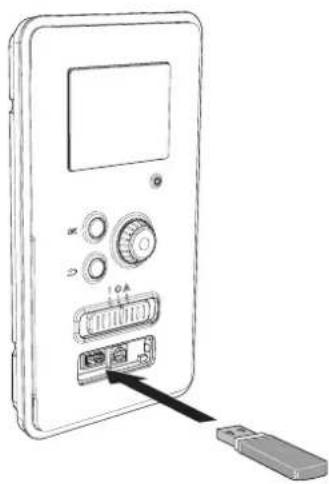
natural_image
Line drawing of a device with ports and an attached USB port, no text or symbols presentRC-HY20/40 is equipped with a USB socket in the display unit. This USB socket can be used to connect a USB memory to update the software, save logged information and handle the settings in RC-HY20/40.

When a USB memory is connected a new menu (menu 7) appears in the display.
Menu 7.1 - update firmware

This allows you to update the software in RC-HY20/40.
NOTE
For the following functions to work the USB memory must contain files with software for RC-HY20/40.
This information states which product the software is intended for, the software version and general information about them. If you wish to select another file than the one selected, the correct file can be selected by "choose another file".
start updating
Select "start updating" if you want to start the update.
You are asked whether you really want to update the software. Respond "yes" to continue or "no" to undo.
If you responded "yes" to the previous question the update starts and you can now follow the progress of the update on the display. When the update is complete RC-HY20/40 restarts.
NOTE
A software update does not reset the menu settings in RC-HY20/40.
NOTE
If the update is interrupted before it is complete (for example power cut etc.) the software can be reset to the previous version if the OK button is kept pressing during start up until the green lamp starts to illuminate (takes about 10 seconds).
choose another file

Select "choose another file" if you do not want to use the suggested software. When you scroll through the files, information about the marked software is shown in a fact box just as before. When you have selected a file with the OK button you will return to the previous page (menu 7.1) where you can choose to start the update.
Menu 7.2 - logging
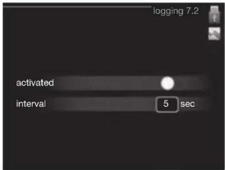
Setting range: 1 s - 60 min
Factory setting range: 5 s
You can set the interval of the log data storage and start saving the log data on the USB memory.
- Set the desired interval between loggings.
- Tick "activated".
- The present values from RC-HY20/40 are saved in a file in the USB memory at the set interval until "activated" is unticked.
NOTE
Untick "activated" before removing the USB memory. Menu 7.3 - manage settings
Menu 7.3 - manage settings
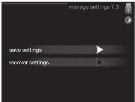
Here you can manage (save as or retrieve from) all the menu settings (user and service menus) in RC-HY20/40 with a USB memory.
Via "save settings" you save the menu settings to the USB memory in order to restore them later or to copy the settings to another RC-HY20/40.
NOTE
When you save the menu settings to the USB memory you replace any previously saved settings on the USB memory.
Via "recover settings" you reset all menu settings from the USB memory.
NOTE
Reset of the menu settings from the USB memory cannot be undone.
Disturbance in comfort
In most cases, the control module notes a malfunction and indicates this with alarms and shows instructions to rectify it in the display. See "Manage alarm" for in- formation about managing alarms. If the malfunction does not appear in the display, or if the display is not lit, the following troubleshooting guide can be used.
Manage alarm

In the event of an alarm, some kind of malfunction has occurred, which is indicated by the status lamp changing from green continuously to red continuously. In addition, an alarm bell appears in the information window.
Alarm
In the event of an alarm with a red status lamp a malfunction has occurred that the heat pump and/or control module cannot remedy itself. In the display, by turning the control knob and pressing the OK button, you can see the type of alarm it is and reset it. You can also choose to set the installation to aid mode.
info / action Here you can read what the alarm means and receive tips on what you can do to correct the problem that caused the alarm.
reset alarm In most cases it is enough to select "reset alarm" to correct the problem that caused the alarm. If a green light illuminates after selecting "reset alarm" the alarm has been remedied. If a red light is still visible and a menu called "alarm" is visible in the display, the problem that caused the alarm remains. If the alarm disappears and then returns, see the troubleshooting section (page 78 and 79).
aid mode "aid mode" is a type of emergency mode. This means that the installation produces heat and/or hot water despite there being some kind of problem. This can mean that the heat pump's compressor is not running. In this case any electrical addition produces heat and/or hot water.
NOTE
To select aid mode an alarm action must be selected in the menu 5.1.4.
CAUTION
Selecting "aid mode" is not the same as correcting the problem that caused the alarm. The status lamp will therefore continue to be red.
Troubleshooting
If the operational interference is not shown in the display the following tips can be used:
Basic actions
Start by checking the following possible fault sources:
■ The switch's (SF1) position.
■ Group and main fuses of the accommodation.
■ The property's earth circuit breaker.
■ The control module's miniature circuit breaker (FA1).
Low hot water temperature or a lack of hot water
This part of the fault-tracing chapter only applies if the water heater is installed in the system.
■ Closed or choked fi lling valve for the hot water heater.
- Open the valve.
■ Mixing valve (if there is one installed) set too low.
- Adjust the mixer valve.
■ Control module in incorrect operating mode.
- If mode "manual" is selected, select "addition".
■ Large hot water consumption.
- Wait until the hot water has heated up. Temporarily increased hot water capacity (temporary lux) can be activated in menu 2.1.
■ Too low hot water setting.
- Enter menu 2.2 and select a higher comfort mode.
■ Too low or no operating prioritisation of hot water.
- Enter menu 4.9.1 and increase the time for when hot water is to be prioritised.
Low room temperature
■ Closed thermostats in several rooms.
- Set the thermostats to max, in as many rooms as possible. Adjust the room temperature via menu 1.1, instead of choking the thermostats.
■ Control module in incorrect operating mode.
— Enter menu 4.2. If mode "auto" is selected, select a higher value on "stop heating" in menu 4.9.2.
- If mode "manual" is selected, select "heating". If this is not enough, select "addition".
■ Too low set value on the automatic heating control.
- Enter menu 1.1 "temperature" and adjust the offset heating curve up. If the room temperature is only low in cold weather the curve slope in menu 1.9.1 "heating curve" needs adjusting up.
■ Too low or no operating prioritisation of heat.
- Enter menu 4.9.1 and increase the time for when heating is to be prioritised.
■ "Holiday mode" activated in menu 4.7.
- Enter menu 4.7 and select "Off".
■ External switch for changing the room heating activated.
- Check any external switches.
■ Air in the climate system.
- Vent the climate system.
■ Closed valves to the climate system.
- Open the valves.
■ Incorrectly adjusted flow across the heat pump.
- Check whether alarm high condenser in (163) or high condenser out (162) is in the alarm log. Follow the instructions for adjusting charge flow.
High room temperature
■ Too high set value on the automatic heating control.
- Enter menu 1.1 (temperature) and reduce the offset heating curve. If the room temperature is only high in cold weather the curve slope in menu 1.9.1 "heating curve" needs adjusting down.
■ External switch for changing the room heating activated.
- Check any external switches.
Low system pressure
■ Not enough water in the climate system.
- Top up the water in the climate system.
The compressor does not start
■ There is no heating requirement.
- The heat pump does not call on heating nor hot water.
■ Temperature conditions tripped.
- Wait until the temperature condition has been re-set.
■ Minimum time between compressor starts has not been reached.
- Wait 30 minutes and check if the compressor has started.
■ Alarm tripped.
– Follow the display instructions.
Additional heating only
If you are unsuccessful in rectifying the fault and are unable to heat the house, you can, whilst waiting for assistance, continue running the heat pump in "add. heat only". This means that additional heating only is used to heat the house.
Set the installation to additional heat mode
- Go to menu 4.2 op. mode.
- Mark "add. heat only" using the control knob and then press OK button.
Return to the main menus by pressing the Back button.
CAUTION
When commissioning without MTH air/water heat pump an alarm communication error may appear in the display.
The alarm is reset if the relevant heat pump is deactivated in menu 5.2.2 ("installed heat pump").
Alarm list
| Alarm nr. | Alarm text on the display | Description May be due to | |
| 157 Low | lp cooling Protection against freezing in water HX during cooling operation | ■ Low/no water flow | |
| 162 High | condenser out temperature | Too high temperature out from the condenser. Self-resetting. | ■ Low flow during heating operation■ Too high set temperatures |
| 163 High | condenser in temperature | Too high temperature into the condenser. Self-resetting. | ■ Temperature generated by another heat source |
| 183 Defrosting in progress Not an alarm, but an operating status. ■ Set when the heat pump runs the defrosting procedure | |||
| 220 High | pressure alarm BP4 has been above 4,15MPa 5 times within 60 minutes. | ■ Insuffi cient air circulation or blocked heat exchanger■ Expansion valve not correctly connected■ Service valve closed■ Defective control board in FDCW■ Low or no flow during heating operation■ Defective circulation pump■ Defective fuse, F(4A) | |
| 221 Low | pressure alarm Tool low value on the low pressure sensor 3 times within 60 minutes | ■ Open circuit or short circuit on input for low pressure sensor■ Defective low pressure sensor■ Defective control board in FDCW■ Open circuit or short circuit on input for suction gas sensor (Tho-S)■ Defective suction gas sensor (Tho-S) | |
| 223 Com | fl t from the heat pump | Communication between the control board and the communication board is interrupted. There must | ■ Any circuit breakers for FDCW off■ Incorrect cable routing |
| 224 Fan | alarm from heat pump | Deviations in the fan speed in FDCW. ■ The fan | cannot rotate freely■ Defective control board in FDCW■ Defective fan motor■ Control board in FDCW dirty■ Fuse (F2) blown |
| 228 | Failed defrosting | 10 aborted defrost due to alarm: 418,419 or 343 | ■ Too low water flow■ Too low return temperatur |
| 230 Hot gas alarm | Temperature deviation on the hot gas sensor (Tho-D) twice within 60 minutes or for 60 minutes continuously. | ■ Sensor does not work (see section "Ambient temperature sensor")■ Insuffi cient air circulation or heat exchanger■ Blocked■ If the fault persists during cooling, there may be an insufficient amount of refrigerant.■ Defective control board in FDCW | |
| 261 High | HWX temp Temperature deviation on the heat exchanger sensor (Tho-R1/R2) fi ve times within 60 minutes or for 60 minutes continuously. | ■ Sensor does not work (see section "Disturbances in comfort")■ Insuffi cient air circulation or blocked heat exchanger■ Defective control board in FDCW■ Too much refrigerant | |
| 262 Inv. err. When IPM (Intelligent power module) displays FO-signal (Fault Output) fi ve times during a 60-minute period. | Can occur when 15V power supply to the inverter PCB is unstable. | ||
| 263 Inv. err. Voltage from the inverter outside the parameters four times within 30 minutes. | ■ Incoming power supply interference■ Service valve closed■ Insuffi cient amount of refrigerant■ Compressor fault■ Defective circuit board in FDCW | ||
| 264 Communication error with inverter. | Communication between circuit board for inverter and control board broken. | ■ Open circuit in connection between boards■ Defective low pressure sensor■ Defective circuit board for inverter in FDCW■ Defective control board in FDCW | |
| 265 Inv. err. Continuous deviation on power transistor for 15 minutes. | ■ Defective fan motor■ Defective circuit board in FDCW | ||
| 266 Low refrig Insuffi cient refrigerant is detected upon star-up cooling mode. | ■ Service valve closed■ Loose connection sensor (BT15, BT3)■ Defective sensor (BT15, BT13)■ Too little refrigerant | ||
| 267 Inv. err. Failed start for compressor ■ Defective circuit board in FDCW | ■ Defective control board in FDCW■ Compressor fault | ||
| 268 Inv. err. Overcurrent, Inverter A/F module ■ Sudden power failure | |||
| 271 Lw otd tmp Temperature of BT28 below the value that permits operation | ■ Cold weather conditions■ Sensor fault | ||
| 272 High otd tmp Temperature of BT28 above the value that permits operation | ■ Warm weather conditions■ Sensor fault | ||
| 277 Sensor fault from heat pump | Sensor fault, heat exchanger in FDCW(Tho-R). | ■ Open circuit or short circuit on sensor input■ Sensor does not work (see section "Disturbances in comfort")■ Defective control board in FDCW | |
| 278 Sensor fault from heat pump | Sensor fault, outdoor temperature sensor in FDCW (Tho-A). | ■ Open circuit or short circuit on sensor input■ Sensor does not work (see section "Disturbances in comfort")■ Defective control board in FDCW | |
| 279 Sensor fault from heat pump | Sensor fault, hot gas in FDCW (Tho-D). ■ Open | circuit or short circuit on sensor input■ Sensor does not work (see section "Disturbances in comfort")■ Defective control board in FDCW | |
| 280 Sensor fault from heat pump | Sensor fault, suction gas in FDCW (Tho-S) ■ Open | circuit or short circuit on sensor input■ Sensor does not work (see section "Disturbances in comfort")■ Service valve closed■ Defective control board in FDCW | |
| 281 Sensor fault from heat pump | Sensor fault, low pressure transmitter in FDCW. | ■ Open circuit or short circuit on sensor input■ Sensor does not work (see section "Disturbances in comfort")■ Service valve closed■ Defective control board in FDCW■ Fault in the refrigerant circuit | |
| 294 Incompatible heat pump Heat pump and indoor module do not work properly together due to technical parameters. | ■ Outdoor module and indoor module are not compatible. | ||
| 343 Low temp water out Low water out temperature during cooling or tank defrost operation | ■ Too low water flow■ Too low return temperatur | ||
| 347 Temp high press Temporary high pressure alarm ■ No/low water flow | ■ Air in water system | ||
| 403 Sensor fault from PCA 154 | Sensor fault, Sensor incoming water in indoor unit (BT3). | ■ Open circuit or short circuit on sensor input■ Sensor does not work (see section "Disturbances in comfort")■ Defective control board AA23 in indoor unit. | |
| 404 Sensor fault from PCA 154 | Sensor fault, Sensor high pressure heating/low pressure cooling in indoor unit (BP4). | ■ Open circuit or short circuit on sensor input■ Sensor does not work (see section "Disturbances in comfort")■ Defective control board AA23 in indoor unit. | |
| 412 Sensor fault from PCA 154 | Sensor fault, Sensor outgoing water in indoor unit (BT12). | ■ Open circuit or short circuit on sensor input■ Sensor does not work (see section "Disturbances in comfort")■ Defective control board AA23 in indoor unit. | |
| 415 Sensor fault from PCA 154 | Sensor fault, Sensor fluid pipe in indoor unit (BT15). | ■ Open circuit or short circuit on sensor input■ Sensor does not work (see section "Disturbances in comfort")■ Defective control board AA23 in indoor unit. | |
| 418 Low temp water out Anti-freeze protection water heat exchanger during defrost. | ■ Too low water flow | ||
| 419 Freeze prot. exch. defr. Anti-freeze protection water heat exchanger during defrost. | ■ Too low water return temperature | ||
Accessories
EMK300M
Part no. MCD291A013
EMK500M
Part no. MCD291A014
Charge pump CPD 11
Charge pump for heat pump
CPD 11-25M/65
Part no. MCD291A016
CPD 11-25M/75
Part no. MCD291A017
External electric additional heat ELK
These accessories may require accessories card AXC 30 (step controlled addition).
ELK 9M
Immersion heater
9 kW 3 x 400 V
Part no. MCD291A015
Hot water control
VST 05M
Reversing valve, Cu pipe ∅22
Max heat pump size 8 kW
Part no. MCD291A018
VST 11M
Reversing valve, Cu pipe ∅28
(Max recommended output, 17 kW)
Part no. MCD291A019
VST 20M
Reversing valve, Cu pipe ∅35
(Max recommended output, 40 kW)
Part no. MCD291A020
Reversing valve for cooling
VCC 05M
Part no. MCD291A021
VCC 11M
Part no. MCD291A022
Electrical model
MEL 1030M
Part no. MCD291A023
Anode
Anode for tank
Anode T300
Part no. MCD291A024
Anode T500
Part no. MCD291A025
Anode M300
Part no. MCD291A026
Anode M500
Part no. MCD291A027
Technical data
Dimensions and setting-out coordinates
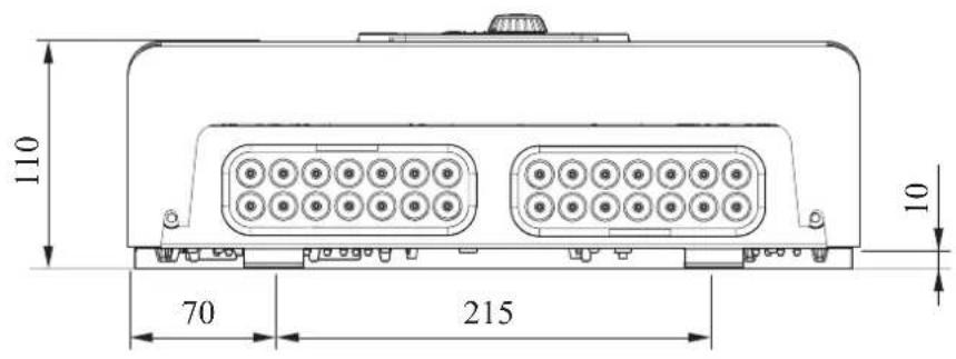

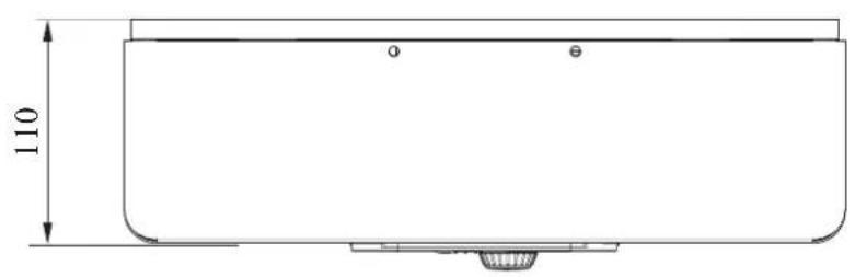
Electrical circuit diagram
HSB100
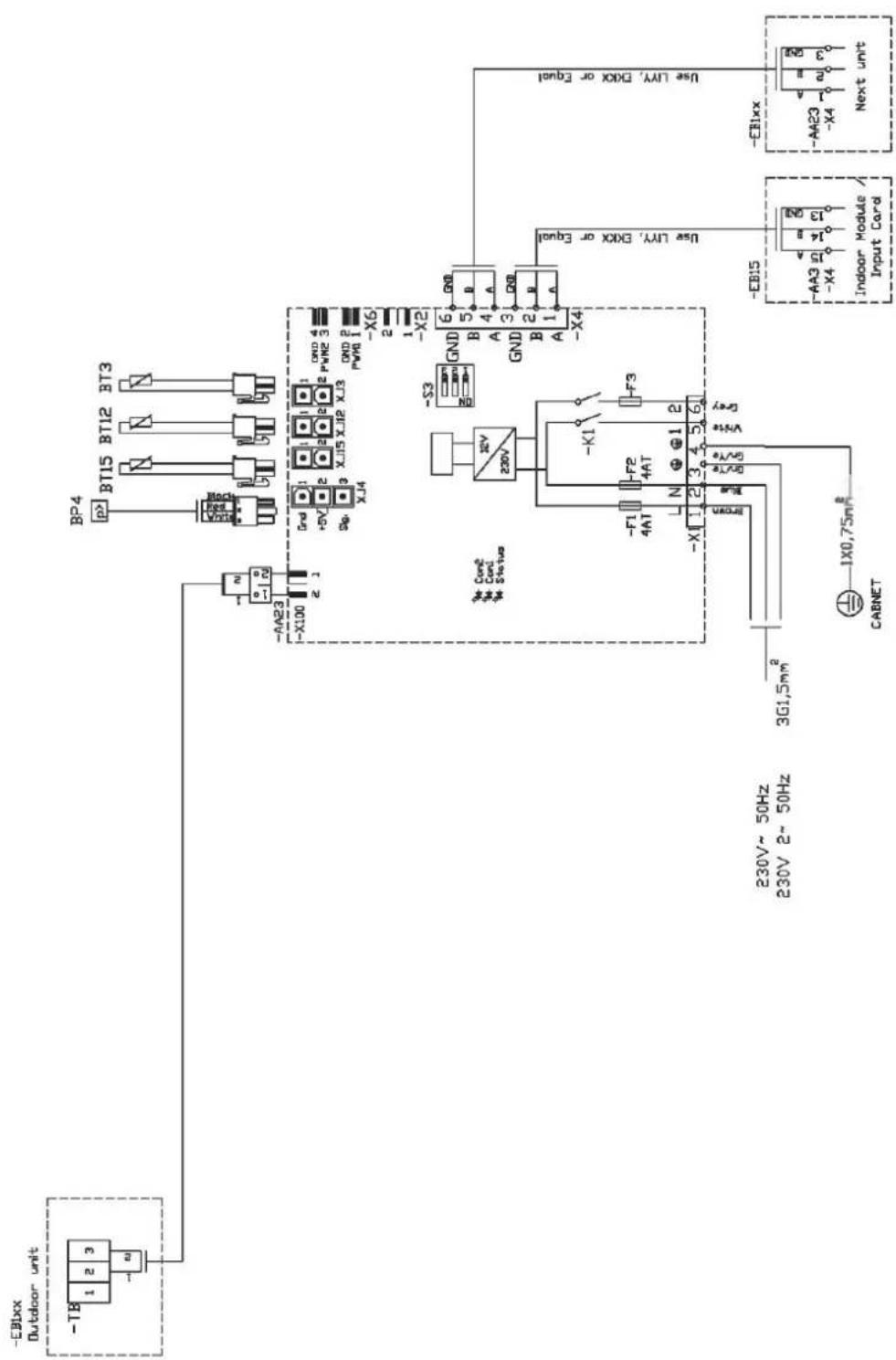
HMK100
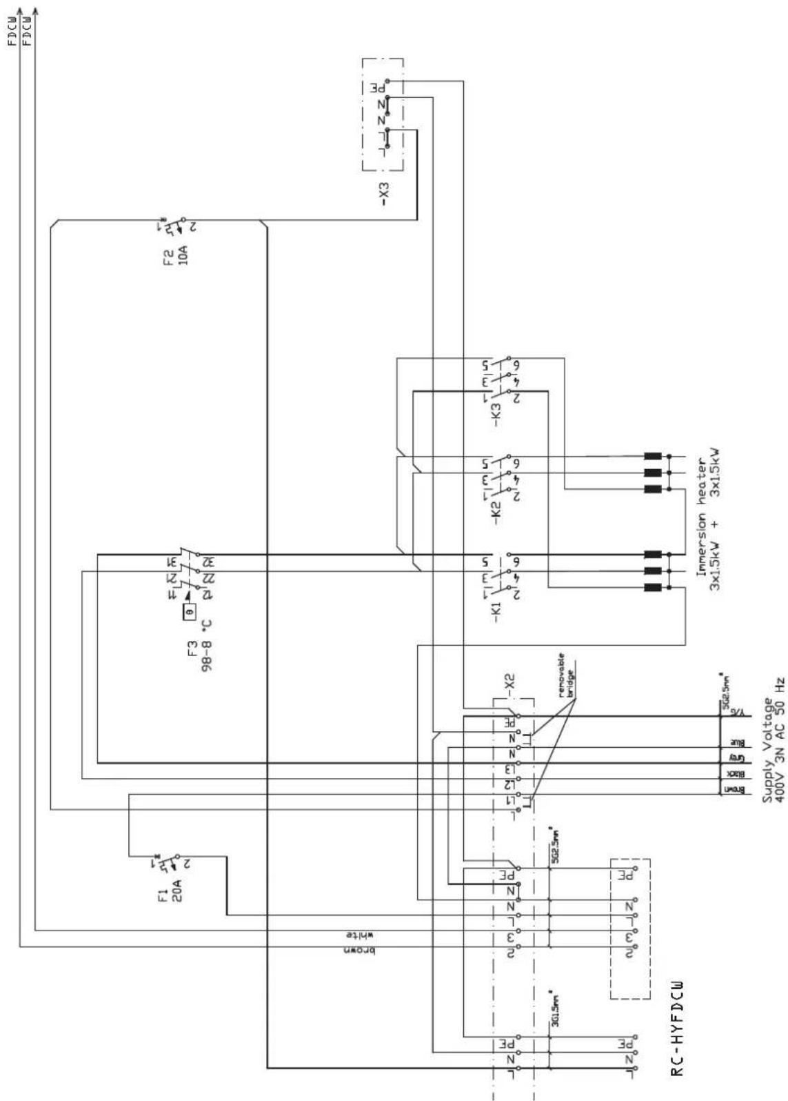

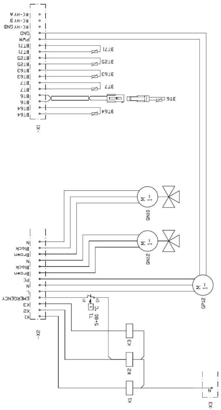
RC-HY20
sheet 1

sheet 2

sheet 3
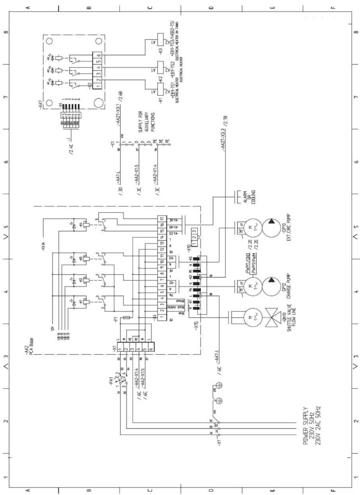
sheet 4

RC-HY40
sheet 1
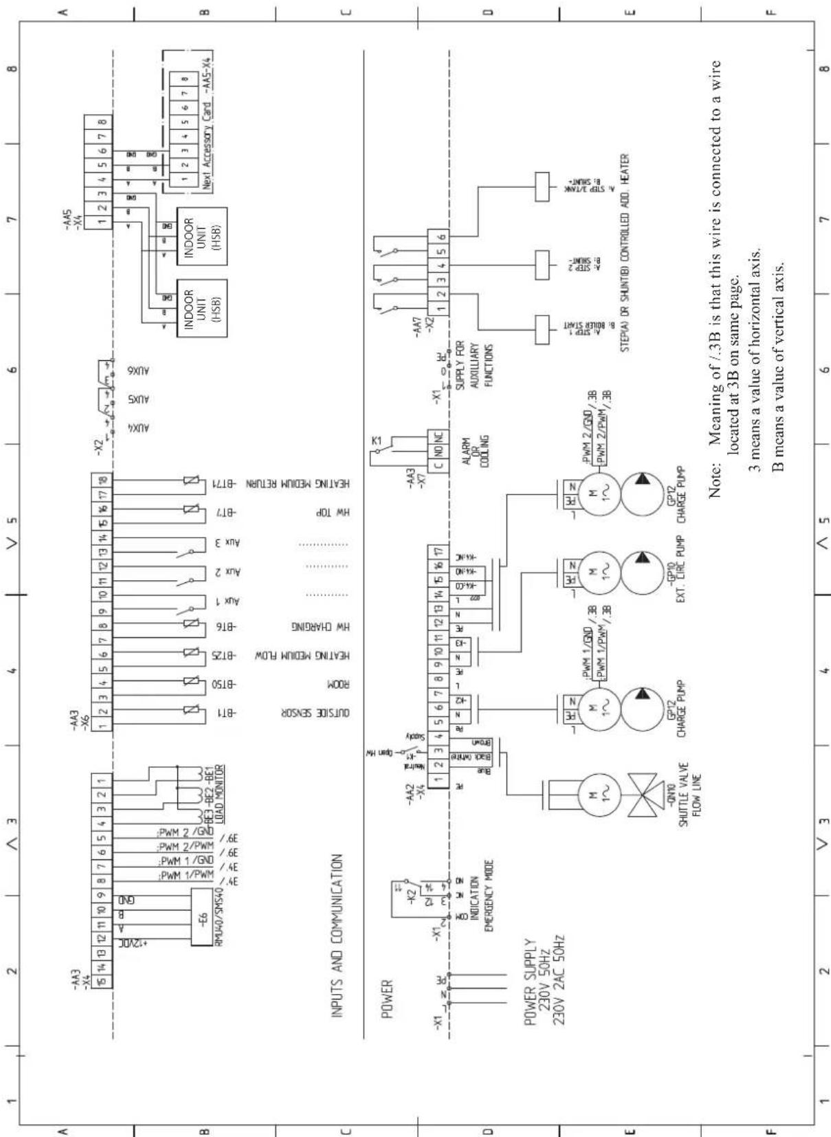
sheet 2

sheet 3

sheet 4

sheet 5
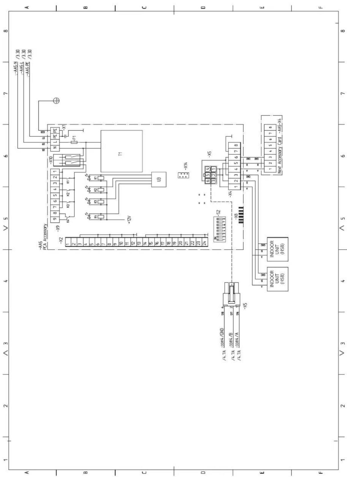
sheet 6


16-5 Konan 2-chome, Minato-ku, Tokyo, 108-8215, Japan
5 The Square, Stockley Park, Uxbridge, Middlesex, UB11 1ET, United Kingdom
Tel: +44-333-207-4072
Fax: +44-333-207-4089
http://www.mhiae.com
Air to Water Heat Pump
Hy drolution (HM)
HSB140/FDCW140VNX
PT500/RC-HY20/RC-HY40
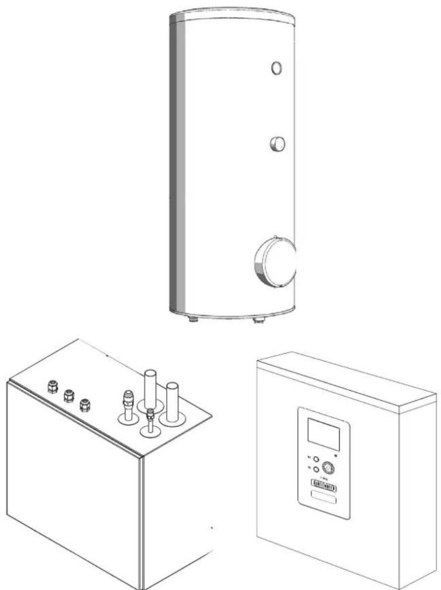
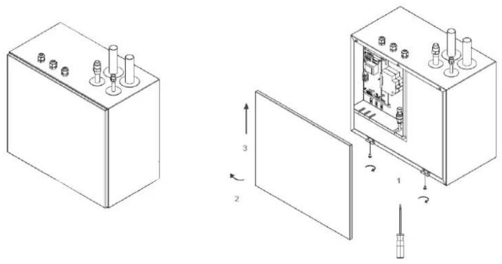
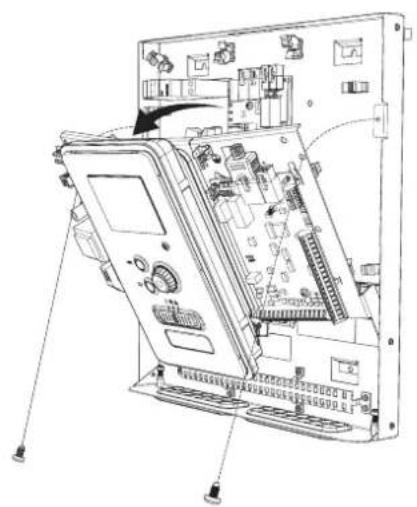
natural_image
Exploded view diagram of an electronic device showing internal components and connections (no text or labels)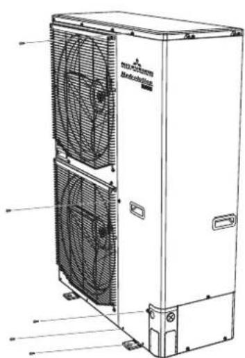
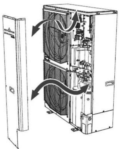
natural_image
Technical line drawing of an internal air conditioning unit with fan and cooling fans, showing internal components and airflow direction (no text or labels)Safety precautions 2
General information for installer 7
Over view and design 7
Transport and storage 9
Supplied components 9
Assembly 9
Hanging indoor unit 11
Hanging control unit 11
Dimensioning expansion vessel 12
Recommended installation order 12
Pipe installation 13
General 13
Installation diagram 13
HSB140 14
System requirements 15
Overflow valve 15
Pump capacity diagram 15
Pressure drop in indoor unit 15
Dimensions and pipe connections 16
HSB140 16
PT500 16
Water circuit 17
Connection to heating system 17
Connection to hot water heater 17
Housing disassembly of tank unit 17
Connecting hot water tank to indoor unit 18
Connecting hot water tank to water main 19
Hot water circulation circuit 20
connection of external heat source 20
Refrigerant circuit 20
Connecting refrigerant pipes 20
Piping insulation 20
Dockings 21
Electrical installation 25
General 25
Electrical components 26
Accessibility, electrical connection for controller ____ 27
Cable lock 29
Connection 29
Power supply 29
Connection between indoor and outdoor unit 29
Connection between indoor unit and controller 30
Cascade connection setting 30
Recommended fuse size for HSB140 30
Recommended cable size for HSB140 30
Power supply 30
Connection between controller and indoor unit ____ 31
HSB140 with RC-HY20 31
HSB140 with RC-HY40 31
Connection between controller and circulation pump (GP12) 31
HSB140 with RC-HY20 31
HSB140 with RC-HY40 32
Connection between controller and 3-way valve (QN10/QN12) _ 32
HSB140 with RC-HY20 32
HSB140 with RC-HY40 33
Connection between controller and sensors 33
RC-HY20 with HSB140 33
RC-HY40 with HSB140 34
Optional connections 35
RC-HY20 35
• Room sensor BT50 35
- Step controlled additional heat 36
- Relay output for emergency mode 36
- External circulation pump 37
- AUX inputs/outputs 37
- myUpway™ 39
RC-HY40 39
- Load monitor 39
• Room sensor BT50 40
- Step controlled additional heat 40
- Relay output for emergency mode 40
- External circulation pump 40
- AUX inputs/outputs 40
- myUpway™ 41
Commissioning and adjusting 42
Preparation 42
Filling and venting 42
Hot water tank 42
Climate system 42
Inspection of installation 42
Start-up and inspection 43
Before start-up 43
Commissioning with heat pump 43
Commissioning with additional heater only 43
3-way valve operation check 43
AUX function check 43
Cooling mode 43
Cleaning particle filter 43
Secondary adjustment 43
Start guide 44
Heating/cooling curve setting 45
Hot water circulation setting 46
SG ready 47
Control 48
Display unit 48
Menu system 49
Menu list 49
Menu 1 – Indoor climate ____ 49
Menu 2 – Hot water 49
Menu 3 – Info 49
Menu 4 – My system ____ 49
Menu 5 – Service 49
Service 61
Disturbances in comfort 64
Manage alarm 64
Troubleshooting 64
Additional heating only 65
Alarm list 66
Accessories 69
Technical data 70
Dimensions and setting-out coordinates 70
Electrical circuit diagram 71
Safety precautions
When installing the unit, be sure to check whether the selection of installation place, power supply specifications, usage limitation (piping length, height differences between indoor and outdoor units, power supply voltage and etc.) and installation spaces.
- We recommend you to read this "SAFETY PRECAUTIONS" carefully before installation in order to gain full advantage of the functions of the unit and to avoid malfunction due to mishandling.
- The precautions described below are divided into ⚠WARNING and ⚠CAUTION. The matters with possibilities leading to serious consequences such as death or serious personal injury due to erroneous handling are listed in the ⚠WARNING and the matters with possibilities leading to personal injury or damage of the unit due to erroneous handling including probability leading to serious consequences in some cases are listed in ⚠CAUTION. These are very important precautions for safety. Be sure to observe all of them without fail.
- Be sure to confirm no anomaly on the equipment by commissioning after completed installation and explain the operating methods as well as the maintenance methods of this equipment to the user according to the owner's manual.
- Keep the installation manual together with owner's manual at a place where any user can read at any time. Moreover if necessary, ask to hand them to a new user.
This heat pump complies with EMC Directive 2014/30/EU.
This appliance is designed for use in a home environment and can be used by children aged from 8 years and above and persons with reduced physical, sensory or mental capabilities or lack of experience and knowledge if they have been given supervision or instruction concerning use of the appliance in a safe way and understand the hazards involved. Children
shall not play with the appliance. Cleaning and user maintenance shall not be made by children without supervision.
This in accordance to applicable parts of the low voltage directive 2014/35/EU, LVD.
This appliance is also intended for use by experts or trained users in shops, hotels, light industry, on farms and in similar environments.
CE marking is applicable to the area of 50 Hz power supply.
The emission sound pressure level from each Indoor and Outdoor unit is under 70 dB(A).
WARNING
Installation must be carried out by the qualified installer.

If you install the system by yourself, it may cause serious trouble such as water leaks, electric shocks, fire and personal injury, as a result of a system malfunction.
Install the system in full accordance with the instruction manual.

Incorrect installation may cause bursts, personal injury, water leaks, electric shocks and fire.
Use the original accessories and the specified components for installation.

If parts other than those prescribed by us are used, It may cause water leaks, electric shocks, fire and personal injury.
When installing in small rooms, take prevention measures not to exceed the density limit of refrigerant in the event of leakage.

Consult the expert about prevention measures. If the density of refrigerant exceeds the limit in the event of leakage, lack of oxygen can occur, which can cause serious accidents.
Ventilate the working area well in the event of refrigerant leakage during installation.

If the refrigerant comes into contact with naked flames, poisonous gas is produced.
After completed installation, check that no refrigerant leaks from the system.

If refrigerant leaks into the room and comes into contact with an oven or other hot surface, poisonous gas is produced.
Hang up the unit at the specified points with ropes which can support the weight in lifting for portage. And to avoid jolting out of alignment, be sure to hang up the unit at 4-point support.
An improper manner of portage such as 3-point support can cause death or serious personal injury due to falling of the unit.
Install the unit in a location with good support.
Unsuitable installation locations can cause the unit to fall and cause material damage and personal injury.
Ensure the unit is stable when installed, so that it can withstand earthquakes and strong winds.
Unsuitable installation locations can cause the unit to fall and cause material damage and personal injury.
Ensure that no air enters in the refrigerant circuit when the unit is installed and removed.
If air enters in the refrigerant circuit, the pressure in the refrigerant circuit becomes too high, which can cause burst and personal injury.
The electrical installation must be carried out by the qualified electrician in accordance with “the norm for electrical work” and “national wiring regulation”, and the system must be connected to the dedicated circuit.
Power supply with insufficient capacity and incorrect function done by improper work can cause electric shocks and fire.
Be sure to shut off the power before starting electrical work.
Failure to shut off the power can cause electric shocks, unit failure or incorrect function of equipment.
Be sure to use the cables conformed to safety standard and cable ampacity for power distribution work.
Unconformable cables can cause electric leak, anomalous heat production or fire.
Use the prescribed cables for electrical connection, tighten the cables securely in terminal block and relieve the cables correctly to prevent overloading the terminal blocks.
Loose connections or cable mountings can cause anomalous heat production or fi re.
Arrange the wiring in the control box so that it cannot be pushed up further into
the box. Install the service panel correctly.
Incorrect installation may result in overheating and fire.
Do not perform brazing work in the airtight room.
It can cause lack of oxygen.
Use the prescribed pipes, flare nuts and tools for R410A.
Using existing parts (for R22 or R407C) can cause the unit failure and serious accidents due to burst of the refrigerant circuit.
Tighten the flare nut by using double spanners and torque wrench according to prescribed method. Be sure not to tighten the flare nut too much.
Loose fl are connection or damage on the fl are part by tightening with excess torque can cause burst or refrigerant leaks which may result in lack of oxygen.
Do not open the service valves for liquid line and gas line until completed refrigerant piping work, air tightness test and evacuation.
If the compressor is operated in state of opening service valves before completed connection of refrigerant piping work, air can be sucked into refrigerant circuit, which can cause bust or personal injury due to anomalously high pressure in the refrigerant.
Do not put the drainage pipe directly into drainage channels where poisonous gases such as sulphide gas can occur.
Poisonous gases will flow into the room through drainage pipe and seriously affect the user's health and safety.
Only use prescribed optional parts. The installation must be carried out by the qualified installer.
If you install the system by yourself, it can cause serious trouble such as water leaks, electric shocks, fire.
Do not run the unit with removed panels or protections
Touching rotating equipments, hot surfaces or high voltage parts can cause personal injury due to entrapment, burn or electric shocks.
Be sure to fix up the service panels.
Incorrect fi xing can cause electric shocks or fi re due to intrusion of dust or water.
Do not perform any repairs or modifications by yourself. Consult the dealer if the unit requires repair.
If you repair or modify the unit, it can cause water
leaks, electric shocks or fire.
Do not perform any change of protective device itself or its setup condition

The forced operation by short-circuiting protective device of pressure switch and temperature controller or the use of non specified component can cause fire or burst.
Be sure to switch off the power supply in the event of installation, inspection or servicing.

If the power supply is not shut off, there is a risk of electric shocks, unit failure or personal injury due to the unexpected start of fan.
Consult the dealer or an expert regarding removal of the unit.

Incorrect installation can cause water leaks, electric shocks or fire.
Stop the compressor before disconnecting refrigerant pipes in case of pump down operation.

If disconnecting refrigerant pipes in state of opening service valves before compressor stopping, air can be sucked, which can cause burst or personal injury due to anomalously high pressure in the refrigerant circuit.

CAUTION
Carry out the electrical work for ground lead with care.

Do not connect the ground lead to the gas line, water line, lightning conductor or telephone line's ground lead. Incorrect grounding can cause unit faults such as electric shocks due to short-circuiting.
Use the circuit breaker with sufficient breaking capacity.

If the breaker does not have sufficient breaking capacity, it can cause the unit malfunction and fi re.
Earth leakage breaker must be installed.

If the earth leakage breaker is not installed, it can cause electric shocks.
Do not use any materials other than a fuse with the correct rating in the location where fuses are to be used.

Connecting the circuit with copper wire or other metal thread can cause unit failure and fi re.
Do not install the unit near the location where leakage of combustible gases can occur.

If leaked gases accumulate around the unit, it can
cause fi re.
Do not install the unit where corrosive gas (such as sulfurous acid gas etc.) or combustible gas (such as thinner and petroleum gases) can accumulate or collect, or where volatile combustible substances are handled.

Corrosive gas can cause corrosion of heat exchanger, breakage of plastic parts and etc. And combustible gas can cause fi re.
Secure a space for installation, inspection and maintenance specified in the manual.

Insufficient space can result in accident such as personal injury due to falling from the installation place.
When the outdoor unit is installed on a roof or a high place, provide permanent ladders and handrails along the access route and fences and handrails around the outdoor unit.

If safety facilities are not provided, it can cause personal injury due to falling from the installation place.
Do not use the indoor unit at the place where water splashes may occur.

Since the indoor unit is not waterproof, it can cause electric shocks and fi re.
Do not install or use the system close to the equipment that generates electromagnetic fields or high frequency harmonics.

Equipment such as inverters, standby generators, medical high frequency equipments and telecommunication equipments can affect the system, and cause malfunctions and breakdowns. The system can also affect medical equipment and telecommunication equipment, and obstruct its function or cause jamming.
Do not install the outdoor unit in a location where insects and small animals can inhabit.

Insects and small animals can enter the electric parts and cause damage or fire. Instruct the user to keep the surroundings clean.
Do not use the base flame for outdoor unit which is corroded or damaged due to long periods of operation.

Using an old and damage base flame can cause the unit falling down and cause personal injury.
Do not install the unit in the locations listed below.

- Locations where carbon fi ber, metal powder or
any powder is floating.
- Locations where any substances that can affect the unit such as sulphide gas, chloride gas, acid and alkaline can occur.
- Vehicles and ships.
- Locations where cosmetic or special sprays are often used.
- Locations with direct exposure of oil mist and steam such as kitchen and machine plant.
- Locations where any machines which generate high frequency harmonics are used.
- Locations with salty atmospheres such as coastlines.
- Locations with heavy snow (If installed, be sure to provide base flame and snow hood mentioned in the manual).
- Locations where the unit is exposed to chimney smoke.
- Locations at high altitude (more than 1000m high).
- Locations with ammonic atmospheres.
- Locations where heat radiation from other heat source can affect the unit.
- Locations without good air circulation.
- Locations with any obstacles which can prevent inlet and outlet air of the unit.
- Locations where short circuit of air can occur (in case of multiple units installation).
- Locations where strong air blows against the air outlet of outdoor unit.
It can cause remarkable decrease in performance, corrosion and damage of components, malfunction and fire.
Do not install the outdoor unit in the locations listed below.

- Locations where discharged hot air or operating sound of the outdoor unit can bother neighborhood.
- Locations where outlet air of the outdoor unit blows directly to plants.
- Locations where vibration can be amplified and transmitted due to insufficient strength of structure.
- Locations where vibration and operation sound generated by the outdoor unit can affect seriously. (on the wall or at the place near bed room)
- Locations where an equipment affected by high harmonics is placed. (TV set or radio receiver is placed within 5m)
- Locations where drainage cannot run off safely. It can affect surrounding environment and cause a claim.
Do not install the remote controller at the direct sunlight.

It can cause malfunction or deformation of the remote controller.
Do not use the unit for special purposes such as storing foods, cooling precision instruments and preservation of animals, plants or art.

It can cause the damage of the items.
Take care when carrying the unit by hand.

If the unit weights more than 20kg, it must be carried by two or more persons. Do not carry by the plastic straps, always use the carry handle when carrying the unit by hand. Use gloves to minimize the risk of cuts by the aluminum fins.
Dispose of any packing materials correctly.

Any remaining packing materials can cause personal injury as it contains nails and wood. And to avoid danger of suffocation, be sure to keep the plastic wrapper away from children and to dispose after tear it up.
Pay attention not to damage the drain pan by weld spatter when welding work is done near the indoor unit.

If weld spatter entered into the indoor unit during welding work, it can cause pin-hole in drain pan and result in water leakage. To prevent such damage, keep the indoor unit in its packing or cover it.
Be sure to insulate the refrigerant pipes so as not to condense the ambient air moisture on them.

Insufficient insulation can cause condensation, which can lead to moisture damage on the ceiling, floor, furniture and any other valuables.
Be sure to perform air tightness test by pressurizing with nitrogen gas after completed refrigerant piping work.

If the density of refrigerant exceeds the limit in the event of refrigerant leakage in the small room, lack of oxygen can occur, which can cause serious accidents.
Do not touch any buttons with wet hands.

It can cause electric shocks.
Do not shut off the power supply immediately after stopping the operation.

Wait at least 5 minutes, otherwise there is a risk of water leakage or breakdown.
Do not control the system with main power switch.

It can cause fire or water leakage. In addition, the
fan can start unexpectedly, which can cause personal injury.
Do not touch any refrigerant pipes when the system is in operation.
During operation the refrigerant pipes become extremely hot or extremely cold depending the operating condition, and it can cause burn injury or frost injury.
This manual is only for outdoor units connected to HSB series and HMK series.
When you connect other indoor units to outdoor units, please refer to other manual.
Notabilia for units designed for R410A
Only use R410A refrigerant. R410A is the refrigerant whose pressure is 1.6 times as high as that of conventional refrigerant.
The size of charging port of service valve and check joint for R410A are altered from that for conventional refrigerant in order to prevent the system being charged with the incorrect refrigerant by mistake. And the protruding dimension of pipe for flare processing and flare nut size for R410A are also altered from that for conventional refrigerant in order to reinforce strength against the pressure for R410A. Accordingly the dedicated tools for R410A listed in the below mentioned table should be prepared for installation and servicing.
| Dedicated tools for R410A | |
| a) | Gauge manifold |
| b) | Charge hose |
| c) | Electronic scale for refrigerant charge |
| d) | Torque wrench |
| e) | Flare tool |
| f) | Protrusion control gauge for copper pipe |
| g) | Vacuum pump adapter |
| h) | Gas leak detector |
Do not use charging cylinder. Using charging cylinder may alter the composition of refrigerant, which results in making the performance of the system worse.
Refrigerant must be charged always in liquid state from the bottle.
General information for installer
For outdoor unit installation information, see Installation manual for Outdoor unit.
Over view and design
HSB140
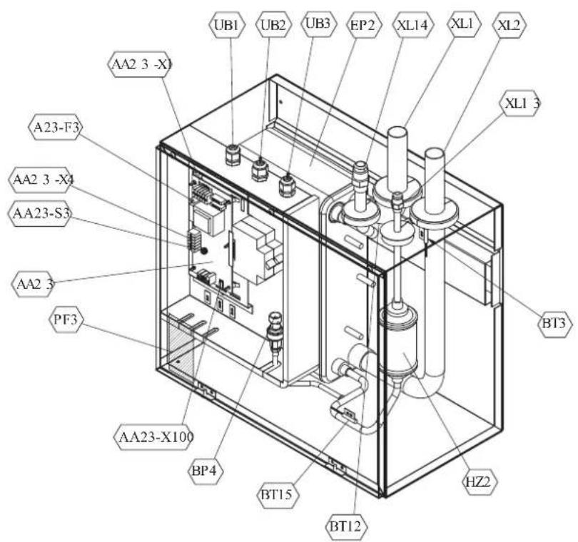
Pipe connections
XL1(Red mark) Climate system supply
XL2 (Blue mark) Climate system return
XL14 Connection, gas line
XL13 Connection, liquid line
Valves etc.
EP2 Heat exchanger
HQ1 Particle filter (supplied)
HZ2 Drying filter
Sensor, thermostats
BP4 Pressure sensor, high pressure
BT3 Temperature sensor, heating medium, return
BT12 Temperature sensor, condenser, supply
BT15 Temperature sensor, fluid pipe
Miscellaneous
UB1 Cable gland
UB2 Cable gland
UB3 Cable gland
Electrical components
AA23 Communication board
AA23-F3 Fuse for external heating cable
AA23-S3 DIP switch, addressing of outdoor unit
AA23-X1 Terminal block, incoming supply, connection of KVR
AA23-X4 Terminal block, communication with indoor module / control module
AA23-X100 Terminal block, communication outdoor module
PT500

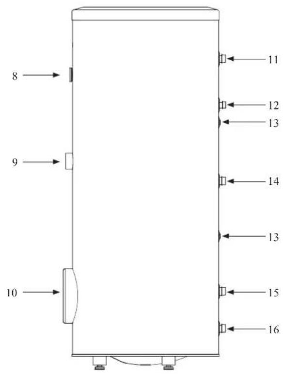
Section of the PT500 storage tanks.
- Upper insulation of the storage tank
- Protective magnesium anode
- Enamelled tank
- Side insulation of the storage tank
- Coil
- Lower insulation of the storage tank
- Adjustable foot
Side view of the PT500 storage tanks.
- Thermometer
- Connector pipe for mounting electric heating unit
- Inspection opening
- Hot water intake connector pipe
- Hot water circulation connector pipe
- Temperature sensor cover
- Coil supply connector pipe
- Connection of return line from the coil
- Cold water supply connector pipe
Transport and storage
Indoor unit and tank unit must be transported and stored vertically in dry conditions.
Supplied components
HSB140 Indoor unit
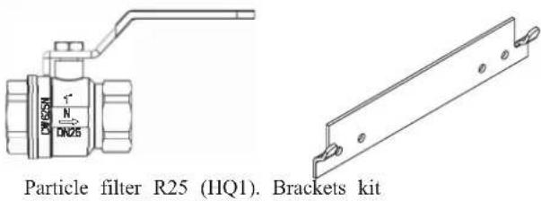
Control unit
RC-HY20/40
Outside sensor
Room sensor (RC-HY40 only)
Insulation tape
Temperature sensor
Aluminium tape
Cable ties
Heating pipe paste
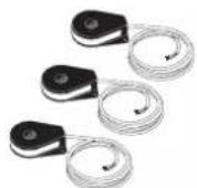
Current sensor (RC-HY40 only)
Assembly
It is recommended that indoor unit is installed in a room with existing floor drainage, most suitably in a utility room or boiler room.
■ For indoor unit and control unit, the mounting surface must be fl rm, fl at and vertical, preferably a concrete wall.
■ Tank unit must be set on a solid waterproof base that would keep the weight of the unit. The height-adjusting legs allow for levelling and stable setting.
PT500
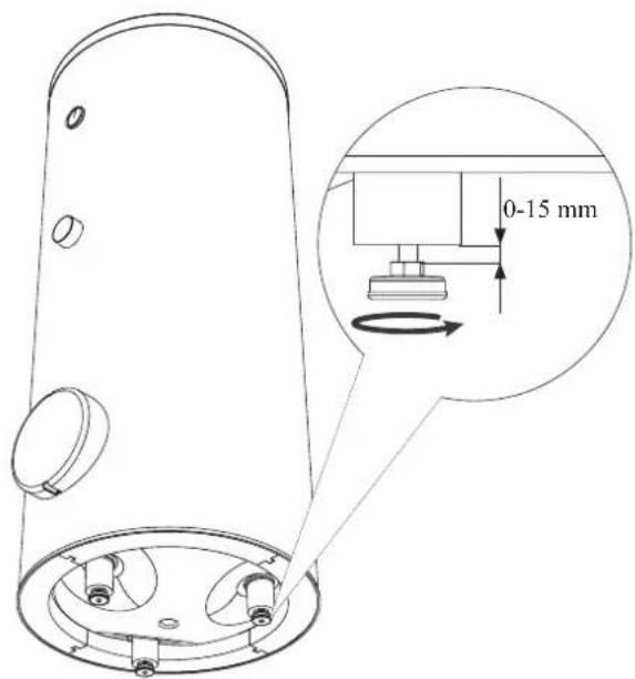
■ Install indoor unit with its back to an outside wall, ideally in a room where noise does not matter. If this is not possible, avoid placing it against a wall behind a bedroom or other room where noise may be a problem.
■ Route pipes so they are not fixed to an internal wall that backs on to a bedroom or living room.
■ Install tank unit and its pipings to indoor unit indoors in order to avoid icing.
■ Ensure free space described in the following figures for future maintenance.
HSB140
Recommendation for positioning on wall
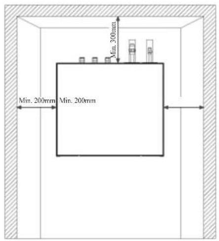
Recommendation for positioning in corner
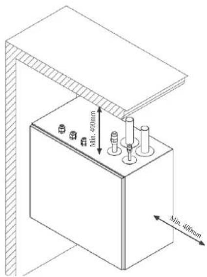
*Min 800mm is required in front
PT500
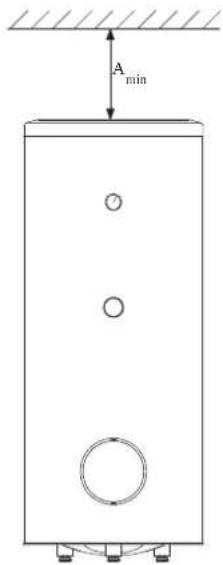
A _min is required on top to replace anode bar, and 500 mm is required in front to replace immersion heater if equipped.
| Application | Connector pipe dia. | Type of anode A | min |
| PT500 | 11⁄4" Chain φ33 × 5 | 150 mm | |
| 3⁄4" Titanium anode 400 mm | |||
RC-HY20/40
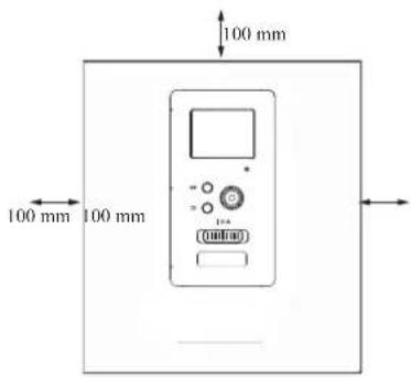
Hanging indoor unit
It is recommended that the split box is installed in a room with existing floor drainage, most suitably in a utility room or boiler room.
- The bracket for the split box is mounted to the wall by use of appropriate screws.

- Insert HSB140 in the bracket mounted to the wall.
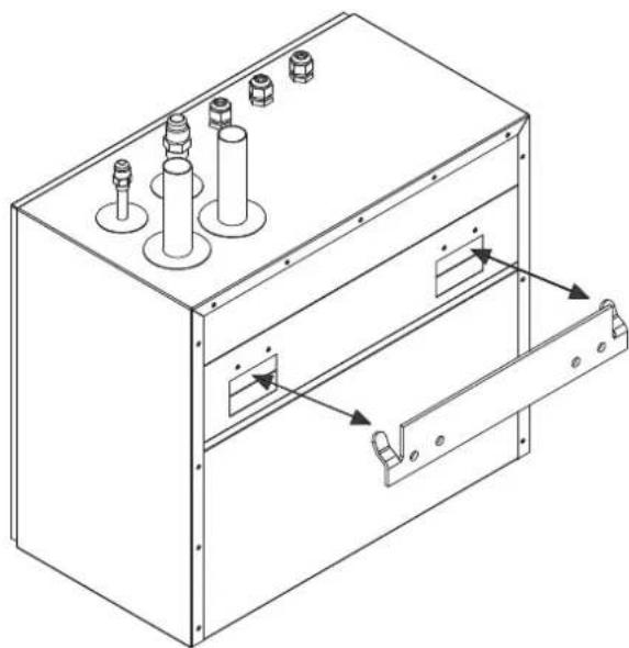
natural_image
Technical line drawing of a mechanical enclosure with multiple cylindrical components and a door handle (no text or symbols)NOTE
Indoor unit weigh 23 kg excluding water inside.
Hanging control unit
Use all mounting points and install control unit upright against a fl at wall. Make sure whole back surface faces the wall.

Dimensioning expansion vessel
The expansion vessel volume must be at least 5% of total water volume in the circulation system.
Initial pressure and max height difference
Recommended maximum height difference between expansion vessel and the highest point in the system is 5m.
The initial pressure of the pressure expansion vessel must be dimensioned according to the maximum height (H) between the vessel and the highest positioned radiator, see figure. An initial pressure of 0.5 bar (5 mvp) means a maximum permitted height difference of 5 m.
If the standard initial pressure in the pressure vessel is not high enough it can be increased by filling via the valve in the expansion vessel. The expansion vessel's standard initial pressure must be entered in the check list on User's manual.
Any change in the initial pressure affects the ability of the expansion vessel to handle the expansion of the water.
Consult local distributor in case height difference exceeds 5m.
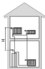
Recommended installation order
-
Hang indoor unit and control unit to appropriate position and connect indoor unit and tank unit.
-
Connect indoor unit to climate system, cold and hot water lines as well as any external heat sources. See page 14. Also see docking descriptions on page 23-24 and further on.
-
Install refrigerant pipes according to the description on the Installation manual for outdoor unit.
-
Connect current limiter, any centralised load control and external contacts as well as the cable between indoor unit and outdoor unit.
-
Connect incoming electricity to indoor unit and/or outdoor unit. See page 29.
-
Follow the commissioning instructions on page 30-41.
Pipe installation
General
Pipe installation must be carried out in accordance with current norms and directives.
A following table shows plumbing necessary for each product.
| Refrigerant Plumbing | ||
| HSB Necessary Necessary | ||
| PT — Necessary | ||
| PC-HY — — | ||
This heat pump system is designed for low or medium temperature heating system. It is recommended water temperature must not exceed 55^ C on supply and 45^ C on
return at lowest design outdoor temperature (DOT) though indoor unit can operate with a return temperature of up to 65^ C and an outgoing temperature from the unit of 65^ C.
Indoor unit is not equipped with shut off valves; these must be installed outside the heat pump to facilitate any future servicing.
Indoor unit can be connected to the radiator system, floor heating system and/or fan convectors.
Safety valve is not equipped with in indoor unit. Make sure to install safety valve in the circuit.
Installation diagram
FDCW140VNX outdoor unit provides heat for space heating and domestic hot water using free energy in the outdoor air within the range of low temperature up to -20^ . Connection between HSB140 and PT500 is shown on the next page. The system is controlled by RC-HY20 or RC-HY40 control unit.
HSB140
HSB140 indoor unit is equipped with plate heat exchanger. It needs to install expansion vessel, shut-off valves, safety valve, electric heater and circulation pump to make a complete heating system. In case domestic hot water is required, 3 way valve and tank is also necessary.

flowchart
graph TD
    A["AA25"] --> B["XL14"]
    B --> C["BT12"]
    C --> D["XL1"]
    D --> E["PT500"]
    E --> F["HP"]
    G["FDCW140"] --> H["PT500"]
    H --> I["HP"]
    J["HP"] --> K["HP"]
    L["HP"] --> M["HP"]
    N["HP"] --> O["HP"]
    P["HP"] --> Q["HP"]
    R["HP"] --> S["HP"]
    T["HP"] --> U["HP"]
    V["HP"] --> W["HP"]
    X["HP"] --> Y["HP"]
    Z["HP"] --> AA["HP"]
| Symbol | Meaning Symbol Meaning | ||
| ↑ | Vent | P | Manometer |
| ☒ | Cut-off valve Circulation pump | ☐ | |
| + | Water tap Particulate filter | ☐ | |
| ☒ | Non-return valve Compressor | ∅ | |
| ☒ | Balancing valve Heat exchange | [756D] | |
| ☐ | Three-way valve Cooling |  | |
| ☒ | Safety valve Central heating sy |  | |
| T | Thermometer Domestic hot wa |  | |
| 9 | Temperature sensor |  | Heating systems Floor heating |
| ⊖ | Diaphragm expansion vessel | ||
System requirements
The minimum water volume in the climate system is subject to the values in the table below. If it is not fulfilled, volume vessel must be installed.
For more options, see the docking description on Page 21. (liter)
| With underf loor cooling application | Without underf loor cooling application | |
| HSB140, FDCW140VNX | 150 150 |
Overflow valve
NOTE
A free flow is required for all docking options, which means that an overflow valve must be installed. The circulation pump may become damaged.
Pump capacity diagram
HSB140
HSB140 is not equipped with circulation pump.
This graph shows the characteristic of CPD11-25M/75.
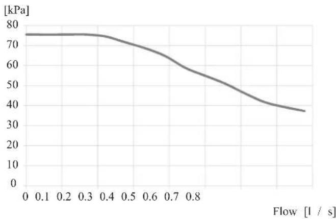
line
| Flow [l / s] | Pressure [kPa] | | ------------ | -------------- | | 0.0 | 75 | | 0.1 | 75 | | 0.2 | 75 | | 0.3 | 74 | | 0.4 | 72 | | 0.5 | 68 | | 0.6 | 62 | | 0.7 | 55 | | 0.8 | 48 | | 0.9 | 40 | | 1.0 | 37 |Pressure drop in indoor unit
HSB140
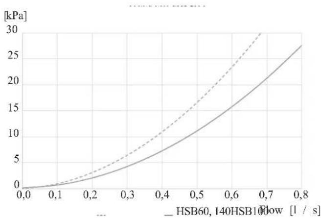
line
| Flow Rate [l / s] | HSB60, 140HSB10Flow [kPa] | | ----------------- | -------------------------- | | 0.0 | 0 | | 0.1 | ~1 | | 0.2 | ~3 | | 0.3 | ~5 | | 0.4 | ~8 | | 0.5 | ~12 | | 0.6 | ~18 | | 0.7 | ~25 | | 0.8 | ~30 |Connection of extra circulation pump
When connecting extra circulation pumps, requirements for pressure, maximum flow etc must be met. See page 24 for location.
NOTE
Non-return valve must be installed in case extra circulation pump is used. See page 24 for the position. The circulation pump may become damaged.
Dimensions and pipe connections
HSB140
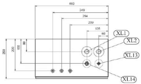
Pipe connections
XL1 (Red mark) Climate system, flow 28mm
XL2 (Blue mark) Climate system, return 28 mm
XL14 Gas line refrigerant, fl are 58
XL13 Liquid line refrigerant, fl are 38
PT500
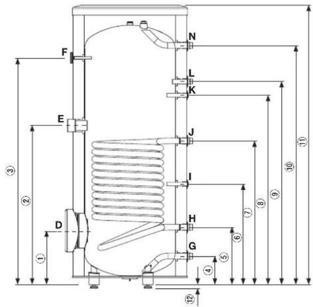
| Connection | U/m | PT500 | |
| D | Inspection opening mm 120 | ||
| E | Heating unit connection inch | 112 "Female | |
| F | Thermometer enclosure mm | 10 Female | |
| N | Hot water outlet inch 1 "Male | ||
| L | Hot water circulation inch | 34 "Male | |
| K | Temp. sensor enclosure (BT7) | mm 16 Female | |
| J | Coil supply | inch 1 "Male | |
| I | Temp. sensor enclosure (BT6) | mm 16 Female | |
| H | Return from coil | inch 1 "Male | |
| G | Cold water input | inch 1 "Male | |
| Dimensions | ||
| PT500 | ||
| 1 | mm | 337 |
| 2 | mm | 967 |
| 3 | mm | 1477 |
| 4 | mm | 188 |
| 5 | mm | 288 |
| 6 | mm | 387 |
| 7 | mm | 805 |
| 8 | mm | 1234 |
| 9 | mm | 1302 |
| 10 | mm | 1545 |
| 11 | mm | 1835 |
| 12 | mm | 21-0/+15 |
Water circuit
Connection to heating system
Connect XL1 to supply line and X2 to return line from heating system.
■ All required safety devices and shut-off valves must be installed as close to the indoor unit as possible.
■ Install bleed valves where necessary, highest point of the water system in usual case.
■ When connecting to a system with thermostats on all radiators, install an overflow valve or remove some of the thermostats to ensure sufficient flow.
■ See section Dockings on page 22 for outline diagram.
■ Install a safety valve with manometer on heating circuit and hot water circuit. (FL2)
For HSB140 install a safety valve for heating circuit on the water pipe returning to indoor unit since it doesn't have port for FL2.
The entire length of the overflow water pipe from the safety valves must be inclined to prevent water pockets and must also be frost proof.
■ The end of overflow water pipe from the safety valves must be left open to the atmosphere. The water may drip from the pipe.
HSB140

Install safety valve as close to XL2 as possible.
Connection to hot water heater
For HSB140 indoor unit, it is necessary to connect PT500 tank unit applying 3 way valve in order to use domestic hot water function.
Housing disassembly of tank unit
Removable housing with thermal insulation facilitates transport and installation of the storage tank. Disassembly the housing in the following order (see next pages fi gure):
- Remove the Temperature gauge, plug of the heating element connector pipe and blanking plate of the inspection opening.
2 Remove the upper cover of the housing together with thermal insulation. - Remove the plugs from the connector pipes and black bushings.
- Remove the fixing screws and the strip connecting the housing jacket.
- Remove the jacket surrounding the tank (housing jacket.)
- Remove the four-piece thermal insulation.
After the installation of the storage tank in its final location, reinstall the removed components in the reverse order.
Housing and thermal insulation disassembly
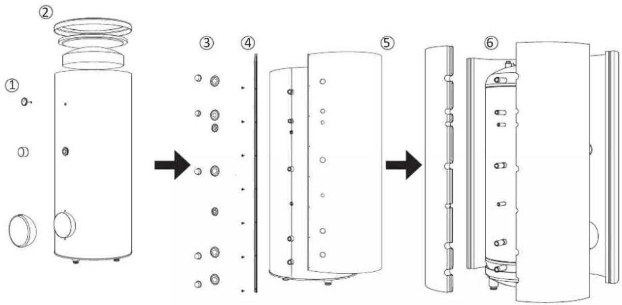
Connecting hot water tank to indoor unit
CAUTION
Installation and commissioning of the storage tank shall only be done by appropriately qualified installer.
The installer should inform the user of the functions of the product and provide the necessary in formation on its safe use.
Information
We recommend installing a strainer in order to protect the pumps, check valve and the components of the heating system.
■ Tank and its pipings to indoor unit must be installed indoors where the temperature wouldn't drop below 15^ C in order to prevent pipings from icing.
■ Maximum piping length between indoor unit and tank is 10 m.
■ Tank unit should be placed on firm, preferably a concrete floor or foundation.
■ Tank unit can be aligned using the adjustable feet.
■ Protection against overpressure shall be made in accordance with the relevant regulations.
■ Connect the heating system according to the installation diagram (see figure).
Installation diagram of the PT storage tank with one coil.

Connecting hot water tank to water main
■ Install a mixing valve if the temperature exceeds 60^ C.
■ It is recommended to install a thermostatic mixing valve for stable temperature hot water supply.
■ Connect the storage tank to the water supply system of water pressure at least 1 bar and max 10 bar. Install a pressure reducer if the pressure at the cold water inlet to the tank is higher than allowed.
■ Install a safety valve which have a maximum 10.0 bar opening pressure on the incoming domestic water line according to outline diagram in order to protect the storage tank against overpressure. Pressure increases during heating the water.
■ During heating the water, small and temporary water flow from the safety valve can occur, which indicates that the pressure has increased above the rated value, which triggered the valve. This may in no way be prevented.
■ Safety valve drain line should be installed with a decline, in an environment free of freezing and remain open to the atmosphere. The manufacturer is not responsible for flooding the room through the safety valve.
■ Blocked safety valve can cause equipment failure. Drain the outflow from the safety valve to the sewerage or drain grate.
■ See section Dockings on page 22 for outline diagram.
■ Connect the water supply system according to the installation diagram.
Installation diagram of the PT storage tank with one coil.
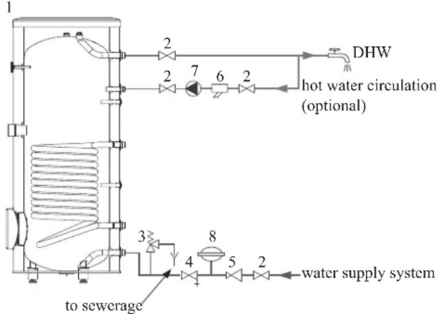
flowchart
graph TD
    A["1"] --> B["2"]
    B --> C["7"]
    C --> D["6"]
    D --> E["2"]
    E --> F["DHW"]
    F --> G["2"]
    G --> H["3"]
    H --> I["4"]
    I --> J["5"]
    J --> K["8"]
    K --> L["to sewerage"]
    K --> M["water supply system"]
    N["hot water circulation (optional)"] --> C
    N --> D
    N --> E
- PT storage tank
- Cut-off valve
- Safety valve
- Drain valve
- Pressure reducer (option, if the pressure in the system exceeds the allowable value)
- Strainer
- Hot water circulating pump
- Hot water expansion vessel
Information
In order to minimize the flow of water from the safety valve associated with the thermal expansion of the liquid, it is advisable to install a suitable expansion vessel at the cold water connection (see item 8.)
CAUTION
Installation of the appropriate safety valve in the cold water supply line protecting the unit against overpressure is mandatory!
CAUTION
Installation of necking of any kind (such as reducers, dirt pockets, etc.) and cut-off valves between the storage tank and the safety valve is not allowed. Only a T-pipe with a drain valve and a T-pipe with an expansion vessel may be installed in these line sections.
CAUTION
Never block the safety valve or drain line. This can cause a dangerous overpressure in the storage tank.
CAUTION
When heating water, slight, temporary discharge from the safety valve can occur. This is a correct safety valve function. Any attempt to interfere in its operation can lead to the danger and destruction of the storage tank.
CAUTION
Never use the equipment with clogged safety valves.
Connection
After the installation and levelling the tank, follow the procedure below (for the connector pipe symbols, refer to page 17):
- Remove protecting plugs from the connector pipes
- Connect the hot water intake line (N).
- Connect the cold water supply line together with the required safety valves (G).
- If the system has the hot water circulation system, connect it to the connector pipe (L). Otherwise, plug the pipe.
- Connect the supply (J) and return (H) of the heating medium to the coil.
CAUTION
If there is an electric heating module installed in the storage tank, fill the tank with water before connecting it to the electrical installation.
Hot water circulation circuit
Hot water circulation function is available for PT500.
PT500
If the system has the hot water circulation system, connect it to the port L (see page 19).
Then install the Cut-off valves, circulation pump and strainer.
Connection of external heat source
External heat source, e.g. a gas or oil boiler or electric heater, can be connected on supply line of heating system (XL1).
Refrigerant circuit
Connecting refrigerant pipes
See Installation manual for outdoor unit.
Piping insulation
Install insulation on all piping in order to avoid condensation during cooling operation.
It is also strongly recommended to insulate piping for heating only application in order to avoid getting burned or reducing the heating capacity.
The thickness of the insulation should be 20mm where the relative humidity exceeds 70%.
Dockings
General
Installation requirements
Hydrolution can be connected in several different ways, some of which are shown on the following pages.
| HSB140 | |
| FDCW140VNX | |
| Max pressure, climate system | 0.25 MPa (2.5 Bar) |
| Highest recommended supply/return temperature | 55/45°C |
| Max temperature, climate system | 65 °C |
| Max temperature in indoor unit | 65 °C |
| Max temperature from external heat source | 65 °C |
| Max supply temperature with compressor at outdoor temp -15°C | 58 °C |
| Min supply temp. cooling | 7 °C |
| Max supply temp. cooling | 25 °C |
| Min volume, climate system during heating, cooling | 150 L |
| Min volume, climate system during underfloor cooling | 150 L |
| Max flow, climate system | 0.79 L/s |
| Min flow, climate system, at 100% circulation pump speed | 0.39 L/s |
| Min flow, climate system | 0.24 L/s |
| Nominal system flow heating (ΔT=5K) | 0.79 L/s (16.5kW, 7/45°C) |
| Nominal system flow cooling (ΔT=5K) | 0.56 L/s (11.8kW, 35/7°C) |
External circulation pump must be used when the pressure drop in the system is greater than the available external pressure. In such cases, a bypass line with non-return valve must be installed.
Use an overflow valve if system flow cannot be guaranteed.
Symbol key
| MeaningSymbol | |
| ↑ | Venting valve |
| ☒ | Shut-off valve |
| ☒ | Non-return valve |
| ☒ | Control valve |
| ☒ | Safety valve |
| ♀ | Temperature sensor |
| Expansion vessel | |
| P | Pressure gauge |
| ☒ | Circulation pump |
| Shunt / shuttle valve | |
| ☒ | Fan |
Docking alternatives
Heating system can be constructed in several different ways combining indoor unit, tank, control unit and other accessories.
For further option information, see page 70.
In the system example shown on the following page, heating, hot water as well as cooling operation are available.
Additional heating is helpful on the cold day of the year as the energy from the air is reduced. It is also recommended as back-up in case the heat pump operation is blocked for any reason (e.g. ambient temperature exceeds the operation limit of heat pump).
NOTE
The heating medium side and the hot water side must be fitted with the necessary safety equipment in accordance with the applicable regulations.
This is the outline diagram. Actual installations must be planned according to applicable standards.
Explanation
AA25 Controller
BT1 Outdoor sensor 1)
BT6 Temperature sensor, hotwater charging 1)
BT7 Temperature sensor, hot water top 1)
BT25 Temperature sensor, external supply line 1)
BT50 Room sensor
BT63 Temperature sensor, external supply line after electric heater
BT71 Temperature sensor, external return line 1)
GP10 Circulation pump, Heating medium
QN10 Reversing valve, Hot water/Heating medium 2)
EB1 Additional heat
EB1 Immersion heater
KA1 Auxiliary relay/Contactor 2)
EB101 Heat pump system
BP4 Pressure sensor, condensor 3)
BT3 Temperature sensor, return line 3)
BT12 Temperature sensor, condenser supply line 3)
BT15 Temperature sensor, fluid pipe 3)
EB101 Heat pump
FL10 Safety valve
GP12 Charge pump 2)
HQ1 Particle filter 3)
QM1 Drain valve, Heating medium
QM31 Shut-off valve, Heating medium, Flow
QM32 Shut off valve, Heating medium, Return
QM43 Shut-off valve
EQ1 Cooling system
BT64 Temperature sensor, cooling supply line 2)
CP6 Single jacket accumulator tank, cooling
GP13 Circulation pump, cooling
QN12 Reversing valve, Cooling/Heating ^2)
Miscellaneous
CM1 Expansion vessel closed, Heating medium
CP5 Buffer vessel
CP10 Accumulator tank with hotwater heating
EB20 Immersion heater
FL2 Safety valve, Heating medium
KA1 Auxiliary relay/Contactor
RN10 Trim valve
1) Included in and supplied with controller
2) Included in and supplied with accessory
3) Included in indoor unit
Installation with indoor unit HSB140, tank PT500, controller RC-HY20/40 with step controlled additional heat before reversing valve for hot water and cooling function (4 pipe system)

flowchart
graph TD
    A["EQ1"] --> B["-AA25"]
    B --> C["CP6-CP6"]
    C --> D["-BP13"]
    D --> E["-BT64"]
    E --> F["--EA25-BT1"]
    F --> G["--EA25-BT50"]
    G --> H["--EB1"]
    H --> I["--KA1"]
    I --> J["--EB1"]
    J --> K["--BT63"]
    K --> L["--EQ1-QN12"]
    L --> M["--FL2"]
    M --> N["--CP10"]
    N --> O["--AA25-BT7"]
    O --> P["--AA25-BT6"]
    P --> Q["--RN10"]
    Q --> R["--FL10"]
    R --> S["--QP12"]
    S --> T["HQ1"]
    T --> U["--QM43"]
    U --> V["--GP12"]
    V --> W["--EZH101"]
    W --> X["--EZ101"]
    X --> Y["--XL14"]
    Y --> Z["--XL13"]
    Z --> AA["--EZ102"]
    AA --> AB["--QB1"]
    AB --> AC["--QB3"]
    AC --> AD["--XL2"]
    AD --> AE["--QM31"]
    AE --> AF["--QM32"]
    AF --> AG["--IIO1"]
    AG --> AH["--FL10"]
    AH --> AI["--QM1"]
NOTE
Not all components are shown in this outline diagram.
Controller (AA25) starts and stops the heat pump (EB101) to meet the heating and hot water demand.
At simultaneous heating and hot water demand, the reversing valve (AA25-QN10) switches periodically between the climate system and the water heater/accumulator tank (CP10). When the hot water heater/accumulator tank is fully charged, the reversing valve switches to the climate system.
Additional heat (EBI) is turned on automatically when the heating demand exceeds the heat pump capacity. This is used for both heating and charging hot water.
The additional heat can also be used for water heater when a higher temperature is required than the heat pump can produce.
During cooling operation, the reversing valve (EQ1-QN12) switches to the cooling system (EQ1). If several simultaneous demands occur while there is a cooling demand, the system reacts differently. In the event of a hot water demand, the reversing valve switches back and hot water is produced until the demand is fulfilled. In the event of a heating demand, the reversing valve switches periodically between cooling and heating. If the cooling demand is met, the reversing valve switches back to basic mode (heating/hot water).
Indoor unit HSB140, tank PT500, controller RC-HY20/40 with step controlled additional heat after reversing valve for hot water and cooling function (4 pipe system)
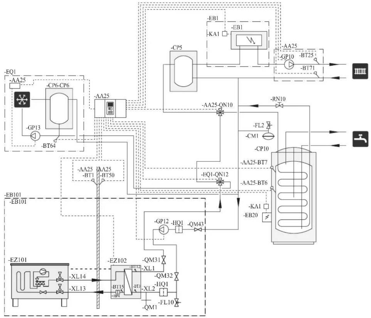
flowchart
graph TD
    A["EQ1"] --> B["AA25"]
    B --> C["CP6-CP6"]
    C --> D["-GP13"]
    D --> E["-BT64"]
    E --> F["AA25"]
    F --> G["AA25-QN10"]
    G --> H["FFQ1-QN12"]
    H --> I["FL2"]
    I --> J["CP10"]
    J --> K["AA25-BT7"]
    K --> L["AA25-BT6"]
    L --> M["KA1"]
    M --> N["EB20"]
    N --> O["FFQ1-QN12"]
    O --> P["FL2"]
    P --> Q["CP10"]
    Q --> R["AA25-BT7"]
    R --> S["AA25-BT6"]
    S --> T["KA1"]
    T --> U["EB20"]
    U --> V["FFQ1-QN12"]
    V --> W["FL2"]
    W --> X["CP10"]
    X --> Y["AA25-BT7"]
    Y --> Z["AA25-BT6"]
    Z --> AA["KA1"]
    AA --> AB["EB20"]
    AB --> AC["FFQ1-QN12"]
    AC --> AD["FL2"]
    AD --> AE["CP10"]
    AE --> AF["AA25-BT7"]
    AF --> AG["AA25-BT6"]
    AG --> AH["KA1"]
    AH --> AI["EB20"]
    AI --> AJ["FFQ1-QN12"]
    AJ --> AK["FL2"]
    AK --> AL["CP10"]
    AL --> AM["AA25-BT7"]
    AM --> AN["AA25-BT6"]
    AN --> AO["KA1"]
    AO --> AP["EB20"]
    AP --> AQ["FFQ1-QN12"]
    AQ --> AR["FL2"]
    AR --> AS["CP10"]
    AS --> AT["AA25-BT7"]
    AT --> AU["AA25-BT6"]
    AU --> AV["KA1"]
    AV --> AW["EB20"]
NOTE
Not all components are shown in this outline diagram.
This installations alternative is suitable for more complex installations with a focus on comfort.
Controller (AA25) starts and stops the heat pump (EB101) to meet the heating and hot water demand of the installation.
At simultaneous heating and hot water demand the reversing valve (AA25-QN10) switches periodically between the climate system and the water heater/accumulator tank (CP10). When the hot water heater/accumulator tank is fully charged, the reversing valve switches to the climate system.
Additional heat (EB1) is turned on, automatically when the heating demand exceeds the heat pump capacity.
Immersion heater (EB20) in the water heater/accumulator tank is used during the time to produce hot water if the heat pump is used for heating at the same time.
The immersion heater (EB20) can also be used if a higher temperature of hot water is required than the heat pump can produce.
During cooling operation, the reversing valve (EQ1-QN12) switches to the cooling system (EQ1). If several simultaneous demands occur while there is a cooling demand, the system reacts differently. In the event of a hot water demand, the reversing valve switches back and hot water is produced until the demand is fulfilled. In the event of a heating demand, the reversing valve switches periodically between cooling and heating. If the cooling demand is met, the reversing valve switches back to basic mode (heating/hot water).
Electrical installation
General
Indoor unit must be installed via an isolator switch in accordance with the local codes and regulations.
■ Disconnect the indoor unit, outdoor unit and control unit before insulation testing of the house wiring.
■ If the building is equipped with an earth-fault breaker, Hydrolution should be equipped with a separate one.
■ For the electrical wiring diagram, see page 71.
■ Do not lay communication, sensor or signal cables for external connection close to high voltage lines.
■ Minimum cross section of communication, sensor or signal cables for external connection must be 0.5mm^2 up to 50 m, for example EKKX, LiYY or equivalent.
■ Use screened three core cable for communication between controller (RC-HY20/40) and indoor unit (HSB140).
■ When laying cables into indoor units and controllers, be sure to route the cable grommet (UB1 AND UB2).
■ Be careful to route cables not to be damaged by metal edge or trapped by panels.
■ Outdoor unit is equipped with a single phase compressor. This means that phase L3 is loaded with up to 25 A during compressor operation.
NOTE
Electrical installation and service must be carried out under the supervision of a qualified electrician. Turn off the circuit breaker before carrying out any servicing.
Electrical installation and wiring must be carried out in accordance with the stipulations in force. Make sure to turn off the power supply during installation.
NOTE
Do not turn on the power on control until the boiler is filled with water.
The circulation pump and immersion heater may become damaged.
NOTE
If the power supply cable is damaged, only authorised person may replace it to avoid danger or damage.
Principle diagram, electrical installation
HSB140
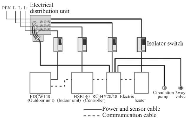
flowchart
graph TD
    A["PEN L1 L2 L3"] --> B["Electrical distribution unit"]
    B --> C["Isolator switch"]
    C --> D["FDCW140 (Outdoor unit)"]
    C --> E["HSB140 (Indoor unit)"]
    C --> F["RC-HY20/40 Controller"]
    C --> G["Electric heater"]
    C --> H["Circulation pump"]
    C --> I["3way valve"]
    B --> J["Power and sensor cable"]
    B --> K["Communication cable"]
| Cable size | |
| Power – Indoor unit 3core, 1 | .5mm ^2 (power cable) |
| Power – Outdoor unit 3core, | 6.0mm ^2 (power cable) |
| Indoor unit – Outdoor unit | 2core, 1.5mm ^2 (communication cable) |
| Indoor unit – Controller | 3core, 0.5mm ^2 , LiYY, EKKX or equivalent (communication cable) |
The cable size shown on the above table is reference value. Choose appropriate size according to local laws and regulations.
Electrical components
HSB140

Explanation
AA23 Communication board
AA23-F3 Fuse for external heating cable
AA23-S3 DIP switch, addressing of outdoor unit
AA23-X1 Terminal block, incoming supply, connection of KVR
AA23-X4 Terminal block, communication with indoor module / control module
AA23-X100 Terminal block, communication outdoor module FDCW
RC-HY20
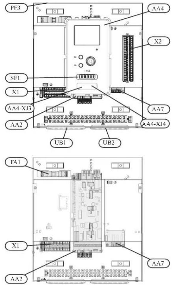
Explanation
AA2 Base card
AA4 Display unit
AA4-XJ3 USB socket
AA4-XJ4 Service outlet (No function)
AA7 Extra relay circuit board
FA1 Miniature circuit-breaker
X1 Terminal block, incoming electrical supply
X2 Terminal block, control signal circulation pump, sensors AUX inputs and heat pump
SF1 Switch
PF3 Serial number plate
UB1 Cable grommet, incoming supply electricity, power for accessories
UB2 Cable grommet, signal
RC-HY40
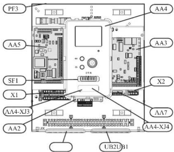
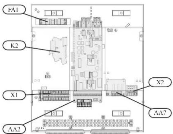
Explanation
AA2 Base card
AA3 Input circuit board
AA4 Display unit
AA4-XJ3 USB socket
AA4-XJ4 Service outlet (No function)
AA5 Accessory card
AA7 Extra relay circuit board
FA1 Miniature circuit-breaker
K2 Emergency mode relay
X1 Terminal block, incoming electrical supply
X2 Terminal block, AUX4 - AUX6
SFI Switch
PF3 Serial number plate
UBI Cable grommet, incoming supply electricity, power for accessories
UB2 Cable grommet, signal
Accessibility, electrical connection for controller
The cover of the control module is opened using a Torx 25 screwdriver. Assembly takes place in the reverse order.
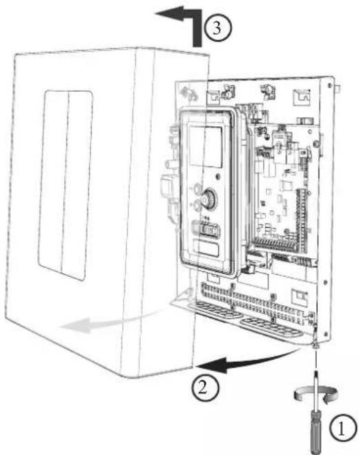
NOTE
The cover to access the base board is opened using a Torx 25 screwdriver
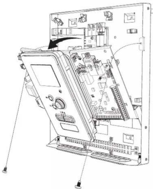
natural_image
Technical line drawing of an electronic device chassis with internal components and wiring (no text or symbols)The display may need to be moved for easier access when connecting electrics. This is easily done by following these steps.
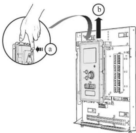
- Press in the catch on the upper rear side of the display unit towards you (a) and move the display unit upwards (b) so that the mountings unhook from the panel.
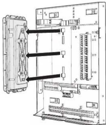
- Lift the display unit from its mountings.
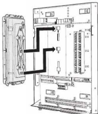
- Align the two lower mountings on the reverse of the display unit with the two upper holes in the panel as illustrated.
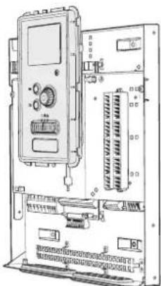
natural_image
Technical line drawing of an electronic control panel with ports and connectors (no text or symbols)-
Secure the display on the panel.
-
When the electrical connection is ready the display must be reinstalled with three mounting points again, otherwise the front cover cannot be installed.
Cable lock
Use a suitable tool to release/lock cables in the terminal block.
HSB140, RC-HY20/40
Terminal block on the electrical card
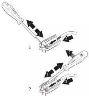
Terminal block
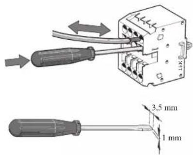
Connection
NOTE
To prevent interference, unscreened communication and/or sensor cables to external connections must not be laid closer than 20 cm from high voltage cables.
HSB140
Power supply
In case of HSB140, power supply is made to indoor unit, outdoor unit and controller separately. 230V 1AC 50Hz is applied.
For indoor unit, incoming supply is connected on AA23-X1 terminal.
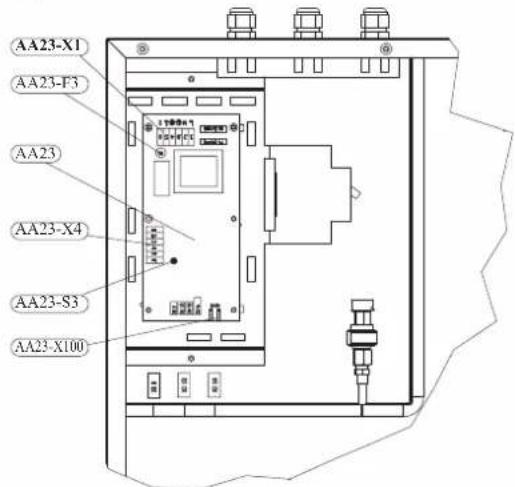
For outdoor unit, incoming supply is connected on TB terminal. See figure on Connection between indoor and outdoor unit.
Connection between indoor and outdoor unit
The communication cable between indoor and outdoor unit is connected between terminal AA23-X100 in indoor unit and TB in outdoor unit. Screened 2 core cable is recommended.
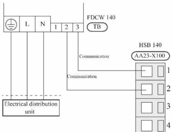
Connection between indoor unit and controller
See Connection for RC-HY20/40
Cascade connection setting
In case of cascade connection system, it is necessary to allot unique address to each indoor unit. Set the dip switch S3-1, -2 and -3 according to the following table.
| Address S3:1 | S3:2 S3:3 | ||
| 1 OFF OFF OFF | |||
| 2 On OFF OFF | |||
| 3 OFF On OFF | |||
| 4 On On OFF | |||
| 5 OFF OFF On | |||
| 6 On OFF On | |||
| 7 OFF On On | |||
| 8 On On On | |||
Recommended fuse size for HSB140
The recommended fuse size shown in the following table is reference value. Choose appropriate size according to local laws and regulations.
| Fuse size | |
| Indoor unit (HSB140) 6A / 230V 1AC 50Hz | |
| Outdoor unit (FDCW140VNX) 30A / 230V 1AC 50Hz | |
| Controller (RC-HY20/40) 10A/ 230V 1AC 50Hz | |
| Electric heater (ELK9M)(reference) | 16 A/400V 3NAC 50Hz |
Recommended cable size for HSB140
The recommended cable size shown in the following table is reference value. Choose appropriate size according to local laws and regulations.
| Cable size | |
| Power – Indoor unit 3core, 1 | .5mm ^2 (power cable) |
| Power – Outdoor unit 3core, | 6.0mm ^2 (power cable) |
| Indoor unit – Outdoor unit | 2core, 1.5mm ^2 (communication cable) |
| Indoor unit – Controller | 3core, 0.5mm ^2 , LiYY, EKKX or equivalent (communication cable) |
RC-HY20/40
Cable connection is different according to the system structure. Refer to the connection method according to the indoor unit.
Power supply
HSB140
Connect power cable on X1 terminal as shown below.
RC-HY 20/40 must be installed via an isolator switch with a minimum breaking gap of 3 mm. Minimum cable area must be sized according to the fuse rating used.
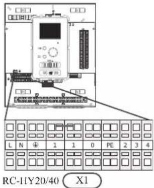
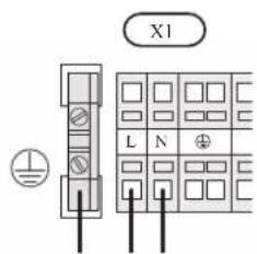
Connection between controller and indoor unit HSB140
Signal cable is connected between controller and indoor unit with screened 3 core cable for HSB140. Choose correct terminal according to the type of controller as shown below.
Connect the port 19(A), 20(B) and 21(GND) on X2 terminal on RC-HY20 to the port 1, 2 and 3 on X4 terminal on AA23 board on HSB140 respectively.
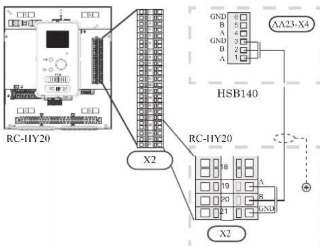
Connect the port 1(A), 2(B) and 3(GND) on X4 terminal on AA5 board on RC-HY40 to the port 1, 2 and 3 on X4 terminal on AA23 board on HSB140 respectively.
In case several systems are connected to one controller, connect the port 4, 5 and 6 on X4 terminal on AA23 board on HSB140 close to the controller to the port 1, 2 and 3 on X4 terminal on AA23 board on another HSB140.

Connection between controller and circulation pump (GP12)
HSB140
For HSB140, circulation pump (GP12) is installed outside of indoor unit. Choose correct terminal according to the type of controller.
Connect the port 5, 6 and 7 on X4 terminal on AA2 board on RC-HY20/40 to the port PE, N and L on circulation pump respectively. Control signal cable is connected between the port 1 and 2 on X2 terminal on RC-HY20 and PWM and GND on circulation pump respectively as shown below.
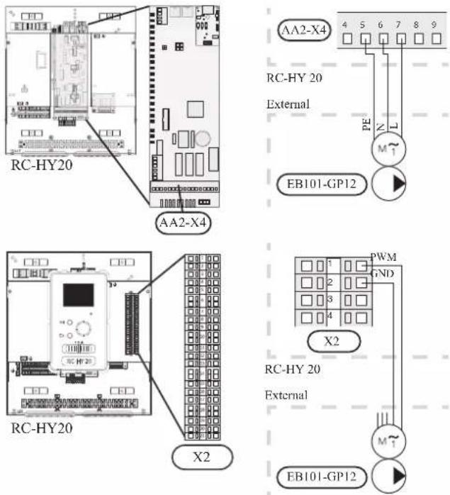
Connect the port 5, 6 and 7 on X4 terminal on AA2 board on RC-HY40 to the port PE, N and L on circulation pump (EB101-GP12) respectively. Control signal cable is connected between the port 7 and 8 on X4 terminal on AA3 board on RC-HY40 and GND and PWM on circulation pump respectively as shown below.

RC-HY40 can connect and control up to two pumps. Connect the port 12, 13 and 15 on X4 terminal on AA2 board on RC-HY40 to the port PE, N and L on second circulation pump (EB102-GP12) respectively. Control cable is connected between the port 5 and 6 on X4 terminal on AA3 board on RC-HY40 and GND and PWM on circulation pump respectively as shown below.

Connection between controller and 3-way valve (QN10/QN12)
3-way valve is used for switching heating / hot water production (QN10), or switching heating / cooling (QN12). Install appropriate valves according to the system structure on site.
HSB140
HSB140 is not equipped with 3-way valve. Install the valves on right position according to the diagram and connect wires on appropriate port according to the type of controller.
• 3-way valve for Heating / Hot water (QN10)
Connect the N, Control and L wire on 3-way valve to the port 2, 3 and 4 on X4 terminal on AA2 board on RC-HY20/40 respectively as shown below.
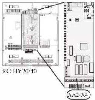
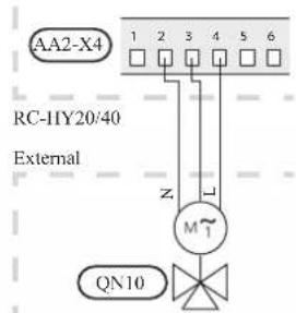
• 3-way valve for Heating / Cooling (QN12)
QN12 can be controlled with potential free variable relay. Connect L and Control wire on 3-way valve to the port 15 and 16 on X4 terminal on AA2 board on RC-HY20 respectively. Also, connect L and N wire to power supply as shown below.
Additional setting is necessary in menu 5.4. See Menu system for details.

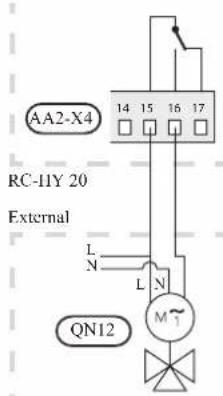
CAUTION
The relay outputs can have a max load of 2 A at resistive load (230V AC).
• 3way valve for Heating / Hot water (QN10)
Refer to 3-way valve connection for HSB140 with RC-HY20.
• 3 way valve for Heating / Cooling (QN12)
QN12 can be controlled with potential free variable relay. Connect L and Control wire on 3-way valve to the port C and NO on X7 terminal on AA3 board on RC-HY40 respectively. Also, connect L and N wire to power supply as shown below.
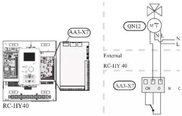
CAUTION
The relay outputs may be subjected to a max load of 2A at resistive load (230V AC).
Connection between controller and sensors
Sensor connection is different according to the combination of indoor unit and controller. Refer to the appropriate combination mentioned below.
Use two-core cable with a minimum 0.5mm2 cross section.
Regarding other sensors not mentioned in this chapter, refer to page 35, Optional connections.
- Ambient air temperature sensor BT1
Install ambient air temperature sensor (BT1) in the shade on a wall facing north or north-west, so it is unaffected by the morning sun.
Connect the sensor to the port 3 and 6 on X2 terminal.
If a conduit is used it must be sealed to prevent condensation in the sensor capsule.
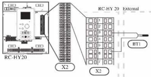
• Hot water charging sensor BT6 (tank bottom)
The temperature sensor, hot water charging (BT6) is placed in the submerged tube on the water heater.
Connect the sensor to the port 5 and 6 on X2 terminal.
Hot water charging is activated in menu 5.2 or in the start guide.
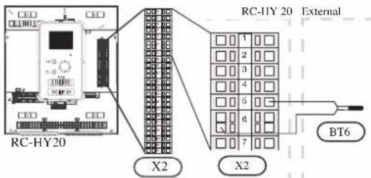
• Hot water sensor BT7 (tank top)
A temperature sensor for hot water top (BT7) can be connected to RC-HY20 to show the water temperature at the top of the tank (if it is possible to install a sensor at the top of the tank).
Connect the sensor to the port 4 and 6 on X2 terminal.
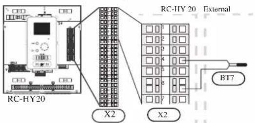
• Temperature sensor BT63, outlet at additional heater
This sensor is used in case electric heater is placed before 3-way valve (QN10) for switching heating/hot water (see page 23 for diagram).
Connect temperature sensor, external supply after electric heater (BT63) to the port 9 and 10 on terminal X2.

• Temperature sensor BT25, outlet for heating
This sensor is used in case electric heater is placed after 3 way valve (QN10) for switching heating/ hot water (see page 24 for diagram).
Connect temperature sensor, external supply (BT25) to the port 8 and 10 on X2 terminal.
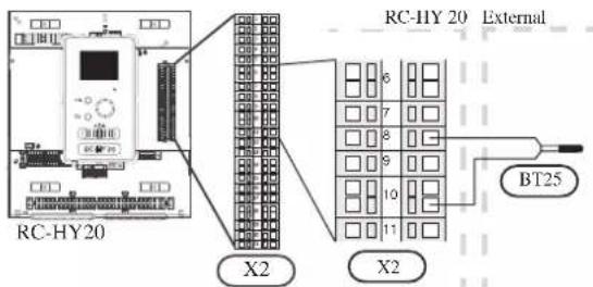
• Temperature sensor BT71, return line for heating
This sensor is used in case electric heater is placed after 3 way valve (QN10) for switching heating/ hot water (see page 24 for diagram).
For connection, see page 37, AUX inputs.
• Temperature sensor BT64, outlet for cooling
This sensor is used in case cooling application is required.
For connection, see page 37, AUX inputs.
- Ambient air temperature sensor BT1
Install ambient air temperature sensor (BT1) in the shade on a wall facing north or north-west, so it is unaffected by the morning sun for example.
Connect the sensor to the port 1 and 2 on X6 terminal on AA3 board.
If a conduit is used it must be sealed to prevent condensation in the sensor capsule.
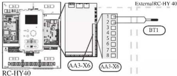
• Hot water charging sensor BT6 (tank bottom)
The temperature sensor, hot water charging (BT6) is placed in the submerged tube on the water heater.
Connect the sensor to the port 7 and 8 on X6 terminal on AA3 board.
Hot water charging is activated in menu 5.2 or in the start guide.
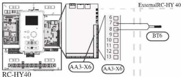
• Hot water sensor BT7 (tank top)
A temperature sensor for hot water top (BT7) can be connected to RC-HY40 to show the water temperature at the top of the tank (if it is possible to install a sensor at the top of the tank).
Connect the sensor to the port 15 and 16 on X6 terminal on AA3 board.
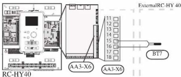
• Temperature sensor BT63, outlet at additional heater
This sensor is used in case electric heater is placed before 3 way valve (QN10) for switching heating/hotwater (see page 23 for diagram).
For connection, see page54, AUX inputs.
• Temperature sensor BT25, outlet for heating
This sensor is used in case electric heater is placed after 3 way valve (QN10) for switching heating/ hot water (see page 24 for diagram).
Connect temperature sensor, external supply line (BT25) to the port 5 and 6 on X6 terminal on AA3 board.

• Temperature sensor BT71, return line for heating
This sensor is used in case electric heater is placed after 3 way valve (QN10) for switching heating/ hot water (see page 24 for diagram).
Connect temperature sensor, external return line (BT71) to the port 17 and 18 on X6 terminal on AA3 board.
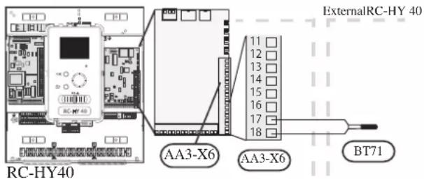
• Temperature sensor BT64, outlet for cooling
This sensor is used in case cooling application is required.
For connection, see page 40, AUX inputs.
Optional connections
RC-HY20
- Room sensor BT50
Room sensor can be connected to controller.
The room temperature sensor has up to three functions:
- Show current room temperature in the control module display.
- Option of changing the room temperature in ^ C.
- Makes it possible to change/stabilise the room temperature. Install the sensor in a neutral position where the set temperature is required. A suitable location is on a free inner wall in a hall approx. 1.5 m above the floor.
Do not install the sensor where correct room temperature cannot be detected such as in a recess, between shelves, behind a curtain, above or close to a heat source, in a draft from an external door or in direct sunlight.
Closed radiator thermostats can also cause problems.
The control module can operate without the sensor, but if user wants to read off the accommodation's indoor temperature in controller display, the sensor must be installed.
Connect the room sensor to the port 7 and 10 on X2 terminal.
If the sensor is to be used to change the room temperature in ^ C and/or to change/stabilise the room temperature, the sensor must be activated in menu 1.9.4.
If the room sensor is used in a room with underfloor heating, it should only have an indicative function, not control of the room temperature.
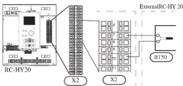
CAUTION
Changes of temperature in accommodation take time. For example, short time periods in combination with underfloor heating will not give a noticeable difference in room temperature.
Use two-core cable with a minimum 0.5mm^2 cross section.
- Step controlled additional heat
NOTE
Mark up any junction boxes with warnings for external voltage.
External step controlled additional heat can be controlled by up to three potential-free relays in the control module (3 step linear or 7 step binary). Alternatively two relays (2 step linear or 3 step binary) can be used for step controlled additional heat, which means that the third relay can be used to control the immersion heater in the water heater/accumulator tank.
Step in occurs with at least 1 minute intervals and step outs with at least 3 seconds intervals.
Step 1 is connected to terminal block X2:2 on the additional relay board (AA7).
Step 2 is connected to terminal block X2:4 on the additional relay board (AA7).
Step 3 or immersion heater in the water heater/accumulator tank is connected to terminal block X2:6 on the additional relay board (AA7).
The settings for step controlled additional heat are made in menu 4.9.3 and menu 5.1.12.
All additional heat can be blocked by connecting a potential-free switch function to the software controlled input on terminal block X2 which is selected in menu 5.4.
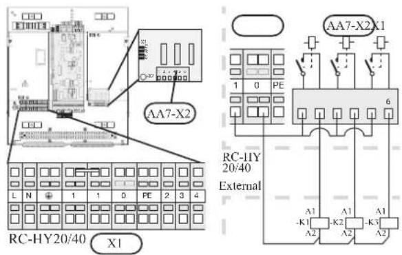
If the relays are to be used for control voltage, bridge the supply from terminal block X1:1 to X2:1, X2:3 and X2:5 on additional relay board (AA7). Connect the neutral from the external additional heat to terminal block X1:0.
Use a cable with appropriate cross section.
For connection, see the installation manual for additional heater.
- Relay output for emergency mode
NOTE
Mark up any junction boxes with warnings for external voltage.
When the switch (SF1) is in " " mode (emergency mode) the circulation pump is activated (EB101-GP12).
CAUTION
No hot water is produced when emergency mode is activated.
The emergency mode relay can be used to activate external additional heat. Between the port 2 and 4 is closed during emergency mode. An external thermostat must be connected to the control circuit (port 4) to control the temperature. Ensure that the heating medium circulates through the external additional heating.
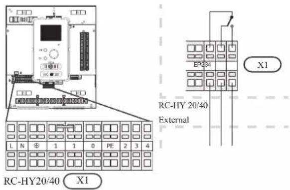
If the relay is to be used for control voltage, bridge the supply from terminal block X1:1 to X1:2 and connect neutral and control voltage from the external additional heat to X1:0 (N) and X1:4 (L).
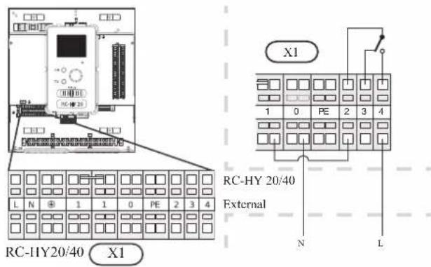
• External circulation pump
Connect the external circulation pump (GP10) to terminal block X4:9 (PE), X4:10 (N) and X4:11 (230 V) on the base board (AA2) as illustrated.

- AUX inputs
Other external inputs are available on the port 11 through 18 on X2 terminal on RC-HY20.
AUX1, 2, 3, 4, 5, and 6 correspond to the port 11, 12, 13, 15, 16 and 17 respectively. Port 14 and 18 are GND and are common to the all auxiliary circuit. Connect a sensor or switch between AUX and GND with a two-core cable with a minimum cross section of 0.5mm ^2 .

Select the appropriate function in menu 5.4.

■ Temperature sensor, cooling/heating (BT74)
Additional room sensor (BT74) is applied in case user wants to determine the operation mode (cooling/heating) with a temperature in a particular room.
This option can be chosen only in case cooling function is available.
■ Temperature sensor, external return line (BT71)
Temperature sensor BT71 is applied in case additional heater is placed after 3-way valve (see page 24 for diagram).
■ Temperature sensor, flow line cooling (BT64)
Temperature sensor BT64 is required in case 4-pipe system is used for cooling operation. (see page 23, 24 for diagram) This option can be chosen only in case cooling function is activated.
■ Contact for external tariff blocking
In cases where external tariff blocking is required it must be connected to terminal block X2.
Tariff blocking means that the additional heat, the compressor, heating and cooling are disconnected by connecting a potential free switch function to the input selected in menu 5.4.
A closed contact results in the electrical output being disconnected.
■ Switch for "SG ready"
NOTE
This function can only be used in mains networks that support the "SG Ready"-standard. "SG Ready" requires two AUX inputs.
This function can only be used in power supply networks that support the “SG Ready” standard. “SG Ready” requires two AUX inputs.
“SG Ready” is a smart tariff management scheme in which electricity supplier can affect indoor and hot water temperature or simply prohibits additional heat and/or the compressor operation in heat pump at certain period of the day. You can choose which operation mode is affected by this function in menu 4.1.5 after the function is activated.
Choose two external input circuits and connect potential-free switches, and set “SG Ready A” and “SG Ready B” in menu 5.4. The system works differently according to the combination of the circuit open/closed.
- Blocking (A: Closed, B: Open)
“SG Ready” is active. Compressor operation and additional heat is prohibited.
• Normal mode (A: Open, B: Open)
“SG Ready” is not active. No effect on the system.
- Low price mode (A: Open, B: Closed)
"SG Ready" is active. The system operates to provide higher capacity than normal mode by using lower tariff electricity. You can select the operation mode (heating/hot water/cooling) affected by this function in menu 4.1.5.
• Overcapacity mode (A: Closed, B: Closed)
“SG Ready” is active. The system supplies higher capacity than Low price mode since the electricity price is supposed to be very low in this mode. You can select the operation mode (heating/hot water/cooling) affected by this function in menu 4.1.5.
■Contact for activation of "temporary lux"
Temporary hot water production function “temporary lux” is activated with this signal. Connect the terminals with a potential-free switch and choose the function in menu 5.4.
"Temporary lux" is activated only when the switch is closed.
■Contact for activation of "external adjustment"
Target temperature offset for supply temperature or room temperature can be done with this signal.
When a room sensor is connected and activated, the target room temperature is offset in ^ C if the switch is closed. When a room sensor is not connected, target supply water temperature (heat curve) is offset instead. The degree of off set can be set in menu 5.4.
■Switch for external alarm
Alarms from external devices can be connected to the control and appear as an info alarm. Potential-free signal of NO or NC type can be connected.
■Switch for external blocking
This function is used in case certain operation mode needs to be prohibited. The operation at selected operation mode is prohibited when the switch is closed. Following functions can be managed.
• Additional heat
- compressor operation
- heating mode
- cooling mode
- hot water mode
- AUX outputs
External output is available on the port 15 to 17 on X4 terminal on AA2 board on RC-HY20. The relay output can have a max load of 2A at resistive load.
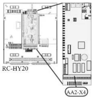

Following functions are available. Select the function in menu 5.4.
• Indication of buzzer alarm
When an alarm occurs, the circuit becomes closed between the port 15 and 16. During normal operation, the port 15 and 17 is closed.
- Cooling mode indication / Active cooling mode (4-pipe cooling)
When the system turns into cooling mode, the circuit becomes closed between the port 15 and 16. By using this signal, it is possible to switch 3-way valve for 4-pipe cooling or to assemble a display circuit indicating cooling mode. For details of connecting the 3-way valve, refer to page 32, 33.
• External pump control (GP10)
External pump (GP10) is used in case additional heater is placed after 3-way valve that switches heating/hot water (refer to page 24 for diagram).
Connect the circulation pump as shown below using the port 15 and 16 on X4 terminal.

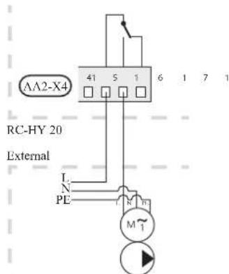
• Hot water circulation pump control (GP11)
In case the distance between hot water tap and hot water storage tank is far, the hot water supply line temperature is likely to drop and it may take time to supply hot water from the tap. In that case, hot water circulation pump (GP11) is applied to maintain hot water supply line temperature warm (refer to page 20 for diagram).
For details of connecting the pump, refer to External pump control (GP10).
NOTE
Mark up any junction boxes with warnings for external voltage.
- myUpway™
Connect the network connected cable (straight, Cat.5e UTP) with RJ45-contact (male) to contact AA4-X9 on the display unit (as illustrated). Use the cable grommet (UB2) in the control module for cable routing.
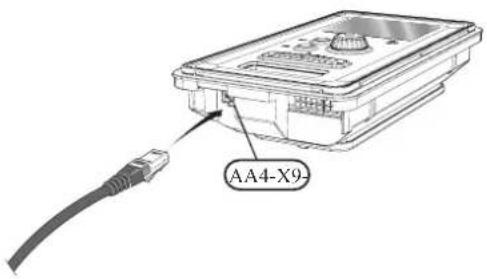
RC-HY40
- Load monitor
In case many power electrical appliances are connected in the property and the electric heater is energised at the same time, there is a risk of tripping the main fuse of the property.
The control module has an integrated load monitor that controls the power steps of the electric heater by disconnecting step by step in the event of overload in a phase. It will be reconnected if other current consumption is reduced.
Connecting current sensors
A current sensor (BE1 - BE3) should be installed on each incoming phase conductor in to the electrical distribution unit to measure the current. This is best done in the electrical distribution unit.
Connect the current sensors to a multi-core cable in an enclosure next to the electrical distribution unit. Use a multi-core cable of at least 0.5 mm ^2 from the enclosure to the heat pump.
Connect the cable to terminal block X4:1 to 4.
X4:1 is the common terminal block for the three current sensors.
Set the size of the property's main fuse in menu 5.1.12.

• Room sensor BT50
Refer to Room sensor BT50 for RC-HY20 for function and installation place.
Connect the room sensor to terminal block X6:3 and X6:4 on the input board (AA3).
If the sensor is to be used to change the room temperature in ^ C and/or to change/stabilise the room temperature, the sensor must be activated in menu 1.9.4.
If the room sensor is used in a room with underfloor heating, it should only have an indicative function, not control of the room temperature.
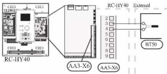
CAUTION
Changes of temperature in accommodation take time. For example, short time periods in combination with underfloor heating will not give a noticeable difference in room temperature.
- Step controlled additional heat
Refer to the explanation for RC-HY20. - Relay output for emergency mode
Refer to the explanation for RC-HY20.
• External circulation pump
Refer to the explanation for RC-HY20.
- AUX inputs
Up to 6 other external inputs are available on RC-HY40.
AUX1 through 3 correspond to the port 9/10, 11/12, 13/14 respectively on X6 terminal on AA3 board. AUX4 through 6 correspond to the port 1, 2 and 3 on X2 terminal on RC-HY40. Port 4 on X2 terminal is GND and is common to AUX4 through 6. Connect a sensor or switch between AUX and GND with a two-core cable with a minimum cross section of 0.5mm².

Select the appropriate function in menu 5.4.
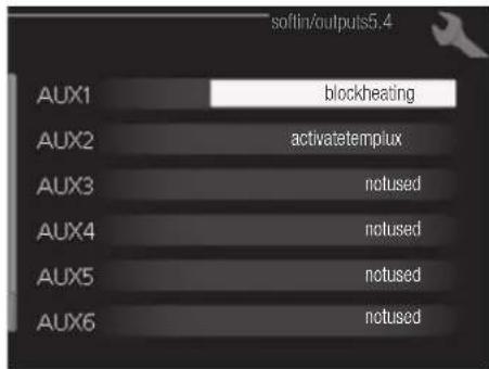
■ Temperature sensor, external supply at additional heat before reversing valve (BT63) Temperature sensor BT63 is applied in case additional heater is placed before 3-way valve (see page 23 for diagram)
The following functions are available. For details, see AUX inputs for RC-HY20.
■ Temperature sensor, cooling/heating (BT74)
■ Temperature sensor, external return line (BT71)
■ Temperature sensor, flow line cooling (BT64)
■ Contact for external tariff blocking
■ Switch for "SG ready"
■Contact for activation of "temporary lux"
■Contact for activation of "external adjustment"
■Switch for external alarm
■Switch for external blocking
- AUX outputs
External output is available on the port NC, NO and C on X7 terminal on AA3 board on RC-HY40. The relay output can have a max load of 2A at resistive load.
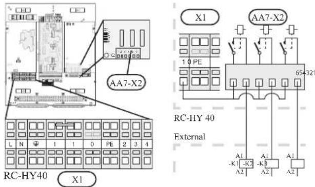
Following functions are available. Select the function in menu 5.4.
• Indication of buzzer alarm
When an alarm occurs, the circuit becomes closed between the port NO and C. During normal operation, the port NC and C is closed.
- Cooling mode indication / Active cooling mode (4-pipe cooling)
When the system turns into cooling mode, the circuit becomes closed between the port NO and C. By using this signal, it is possible to switch 3-way valve for 4-pipe cooling or to assemble a display circuit indicating cooling mode. For details of connecting the 3-way valve, refer to page 32, 33.
• External pump control (GP10)
External pump (GP10) is used in case additional heater is placed after 3-way valve that switches heating/hot water (refer to page 24).
Connect the circulation pump using the port NO and C on X7 terminal on AA3 board as shown below.
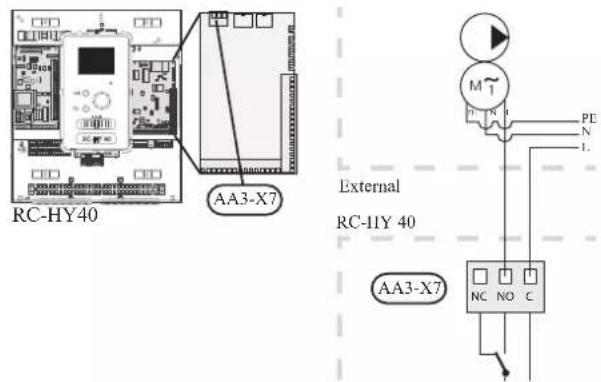
• Hot water circulation pump control (GP11)
In case the distance between hot water tap and hot water storage tank is far, the hot water supply line temperature is likely to drop and it may take time to supply hot water from the tap. In that case, hot water circulation pump (GP11) is applied to maintain hot water supply line temperature warm (refer to page 20 for diagram).
For details of connecting the pump, refer to External pump control (GP10).
NOTE
Mark up any junction boxes with warnings for external voltage.
- myUpway™
Connect the network connected cable (straight, Cat.5e UTP) with RJ45-contact (male) to contact AA4-X9 on the display unit (as illustrated). Use the cable grommet (UB2) in the control module for cable routing.

Commissioning and adjusting Preparations
Before starting commissioning, check the followings;
- The signal cable is connected between indoor unit and outdoor unit as well as indoor unit and controller according to the instruction.
- The power cable is connected to indoor unit, outdoor unit and controller according to the instruction.
- Operation switch in controller is in the position ⏻.
- The service valves on outdoor unit (QM35 and QM36) are open.
- Drain valve is closed before filling water in the system.
• Temperature limiter and electrical switch are not tripped. - The system is filled with water and well vented.
• There are no leaks on the water pipe.
Filling and venting
Hot water tank
- Open the hot water tap as well as venting valve if applicable, and then open the cold water cut-off valve at the inlet.
- Fill the storage tank until obtaining uniform water outflow at the hot water tap, and then close the hot water tap and venting valve.
- Fill the water heater coil in the tank. See Climate system for details.
After the installation and levelling the tank, follow the procedure below (for the connector pipe symbols, refer to page 18):
- Remove protecting plugs from the connector pipes
- Connect the hot water intake line (N).
- Connect the cold water supply line together with the required safety valves (G).
- If the system has the hot water circulati on system, connect it to the connector pipe (L). Otherwise, plug the pipe.
- Connect the supply (J) and return (H) of the heating medium to the coil.
CAUTION
If there is an electric heating module installed in the storage tank, fill the tank with water before connecting it to the electrical installation.
CAUTION
Open the hot water intake valves before heating the system up for the first time or after a longer break in its operation in order to check whether the storage tank is filled with water and the cut-off valve at the cold water inlet is not closed.
Climate system
- Open the vent at the top of the heating system.
- Open all shut-off valves, where installed, so that water flows into all circuits.
- Open the valve for filling the heating circuit and fill it with water.
- Close the vent when water comes out continuously without bubbles.
- Check the manometer and close the fllling valve when the pressure reaches the required value (2 bar is recommended).
- Start the circulation pump of the heating system, and open the vent from time to time and release the all remaining air in the heating system.
- Open safety valve until the pressure of the heating system drops down to about 1 bar. If the pressure drops below 1 bar during venting, add additional water in the circuit.
Inspection of installation
Current regulations require that the climate system is inspected before it is commissioned. The inspection must be carried out by a suitably qualified person and must be documented. Do not replace any part of the system without carrying out new checks.
Start-up and inspection
Before start-up
1 In case of cascade connection, check if each indoor unit has a unique address. See Cascade connection setting on page 25 for details.
2. For an outdoor unit equipped with a crank case heater, it is necessary to supply power 6-8 hours before starting compressor operation to heat the compressor with the heater. To do this, supply power to whole system and disable the compressor operation from menu 5.2.2 on the controller. Disable additional heater as well if necessary.
3. After 6-8 hours, enable the compressor operation in menu 5.2.2 on the controller and enable the additional heater in menu 4.9.2 and 4.9.3 on the controller.
4. Start commissioning by the following steps.
*Step 2 and 3 are not necessary for FDCW60VNX-A.
Commissioning with heat pump
Start guide is shown on the display on the controller when it is turned ON for the first time. Follow the start guide in the display, or choose menu 5.7 to show the start guide. For details, see Start guide on page 58.
Commissioning with additional heater only
Follow the start guide in the display as same as commissioning with heat pump, and then follow the list below.
- Go to menu 4.2 op. mode.
- Mark "add. heat only" using the control knob and then press the OK button.
- Return to the main menus by pressing the Back button.
CAUTION
When commissioning without MHI air /water heat pump an alarm communication error may appear in the display. The alarm is reset if the relevant heat pump is deactivated in menu 5.2.2 ("installed heat pump").
3-way valve operation check
- Activate "AA2-K1 (QN10)" in menu 5.6.
- Check that the reversing valve opens or is open for hot water charging.
- Deactivate "AA2-K1 (QN10)" in menu 5.6.
AUX function check
To check any function connected to the AUX socket,
- Activate "AA2-X4 (RC-HY20)" or "AA3-X7 (RC-HY40)" in menu 5.6.
- Check the desired function.
- Deactivate "AA2-X4 (RC-HY20)" or "AA3-X7 (RC-HY40)" in menu 5.6.
Cooling mode
In case the climate system contains a cooling circuit, activate cooling function in menu 5.11.1.1. After that, you can choose cooling mode indication in menu 5.4 for the AUX output.
Cleaning particle filter
Clean the particle filter (HQ1) after installation.
- Close valve QM31 and the valve by the particle filter (HQ1).
- Open the safety valve (QM20) to ensure that the pressure in HSB60 drops.
- Clean the particle filter (HQ1) as illustrated.
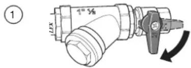

Secondary adjustment
Air is initially released from the hot water and venting may be necessary. If bubbling sounds can be heard from the heat pump, the circulation pump and radiators the entire system will require further venting. When the system is stable (correct pressure and all air eliminated) the automatic heating control system can be set as required
Start guide
NOTE
Fill in the climate system with water before the switch is set to " | "
- Set the control module's switch to "|".
- Follow the instructions in the start guide in the control module display. If the start guide does not start when you start the control module, start it manually in menu 5.7.
TIP
See page 63 for a more in-depth introduction to the installation's control system (operation, menus etc.).
Commissioning
The start guide is displayed when installation is started, It describes what needs to carry out at the first start together with basic settings during installation.
The start guide is displayed so that it cannot be bypassed in order to carry out the start-up correctly. You can start the start guide later in menu 5.7.
During the start-up guide, reversing valves and the shunt are run back and forth to help vent the heat pump.
CAUTION
As long as the start guide is active, no function in the heat pump will start automatically. Each time the controller is ON, the guide will appear until it is completed on the last page.
Operation in the start guide
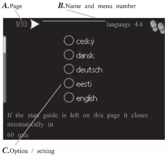
A. Page
You can see the current page of the start guide.
Scroll between the pages of the start guide as follows:
- Turn the control knob until the arrow is marked in the top left corner (at the page number).
- Press OK button to proceed to the next page in the start guide.
B. Name and menu number
You can see the menu name of this page. The number refers to the menu number in the control system.
To read more about affected menus, see the help menu or read the user manual.
C. Option / setting
Make settings for the system here.
D. Help menu
In many menus there is a symbol indicating that extra help is available.
To access the help text:
-
Use the control knob to select the help symbol.
-
Press OK button.
The help text often consists of several windows that you can scroll between using the control knob.
Heating/cooling curve setting
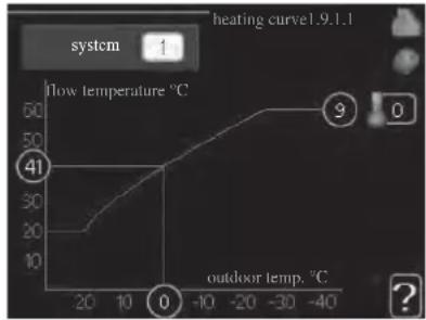
line
| Point | Flow temperature (°C) | Outdoor temp. (°C) | |---|---|---| | 0 | 41 | -40 | | 1 | 20 | -20 | | 2 | 30 | -10 | | 3 | 40 | 0 | | 4 | 50 | -30 | | 5 | 60 | -40 | The chart displays a single data series with 'system' label and 'heating curve'. The values for 'flow temperature' are explicitly labeled: 41, 30, 20, 10, 0, 9.
heating curve
Setting range: 0 - 15
Default value: 9
cooling curve (accessory required)
Setting range: 0 - 9
Default value: 0
The prescribed heating curve for your house can be viewed in the menu heating curve. The task of the heating curve is to give an even indoor temperature, regardless of the outdoor temperature, and thereby energy efficient operation. From this heating curve, the control module determines the temperature of the water to the heating system, supply temperature, and there by the indoor temperature. Select the heating curve and read off how the supply temperature changes at different outdoor temperatures here. If there is cooling function, the same settings can be made for the cooling curve.
Curve coefficient
The heating/cooling curve shows the relation between the target supply temperature and the corresponding outdoor temperature. A steep curve indicates that supply temperature becomes higher at low outdoor air temperature in heating and it becomes lower at high outdoor air temperature in cooling.
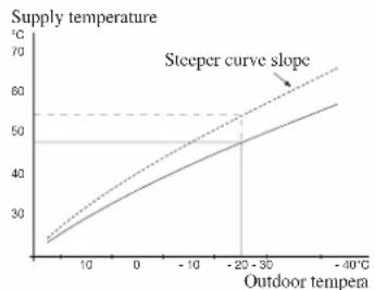
line
| Outdoor tempera | Supply temperature (°C) | | -------------- | ------------------------ | | 0 | 25 | | 10 | 35 | | 20 | 45 | | -20 | 50 | | -40 | 60 |The optimum slope depends on the climate conditions in your location, the type of heating device (radiators or under floor heating) and how well insulated the house is.
The curve is set when the heating installation is installed, but may need adjusting later. Normally, the curve will not need further adjustment.
CAUTION
In the event of making fine adjustments of the indoor temperature, the curve must be offset up or down instead, this is done in menu 1.1 temperature.
Curve offset
The target temperature can be off set in parallel over the entire outdoor temperature range by this function. This is offset by 5 °C by adjusting 2 steps.
The target temperature can be parallel offset in the entire outdoor temperature range with this function. It is offset by 5 °C by adjusting 2 steps.
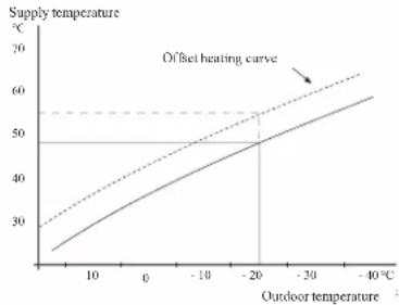
line
| Outdoor temperature (°C) | Supply temperature (°C) | |---|---| | 0 | 25 | | -10 | 35 | | -20 | 45 | | -30 | 50 | | -40 | 55 | Offset heating curveFlow line temperature – maximum and minimum values
This function is used in order to limit max-min supply temperature. The heating / cooling curve becomes fl at beyond max / min target temperature.
CAUTION
Underfloor heating systems are normally max flow line temperature set between 35 and 45°C. Take care not to cause low temperature burns in case it is set higher than 35°C.
Must be restricted with underfloor cooling min. flow line temp. to prevent condensation.
Check the max temperature for your floor with your installer/floor supplier.
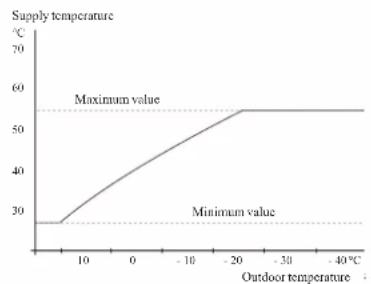
line
| Outdoor temperature (°C) | Supply temperature (°C) | | :--- | :--- | | 0 | 28 | | 10 | 35 | | 20 | 45 | | -20 | 55 | | -30 | 55 | | -40 | 55 |The figure at the end of the curve indicates the curve number. The figure beside the thermometer icon gives the curve off set. Use the control knob to set a new value.
Confir rm the new setting by pressing the OK button.
Curve 0 is an own curve created in menu 1.9.7.
To select another curve (slope):
- Press OK button to access the setting mode
-
Select a new curve. The curves are numbered from 0 to 15, and the bigger number curve has steeper slope.
Curve 0 means that own curve (menu 1.9.7) is used. -
Press OK button to exit the setting.
To read off a curve:
- Turn the control knob so that the ring on the shaft with the outdoor temperature is marked.
- Press OK button.
- Follow the grey line up to the curve and out to the left to read off the value for the supply temperature at the selected outdoor temperature.
- You can now select to take read outs for different outdoor temperatures by turning the control knob to the right or left and read off the corresponding flow temperature.
- Press OK or Back button to exit read off mode.
TIP
Wait 24 hours before making a new setting, so that the room temperature has time to stabilise.
If it is cold outdoors and the room temperature is too low, increase the curve slope by one increment.
If it is cold outdoors and the room temperature is too high, lower the curve slope by one increment.
If it is warm outdoors and the room temperature is too low, increase the curve offset by one increment.
If it is warm outdoors and the room temperature is too high, lower the curve offset by one increment.
Hot water circulation setting
hot water recirc.
operating time
Setting range: 1 - 60 min
Default value: 60 min
downtime
Setting range: 0 - 60 min
Default value: 0 min
Set the hot water circulation for up to three periods per day here. During the set periods the hot water circulation pump will run according to the settings above.
"operating time" decide how long the hot water circulation pump must run per operating instance.
"downtime" decide how long the hot water circulation pump must be stationary between operating instances.
Hot water circulation is activated in menu 5.4 "soft inputs and outputs".
SG Ready
This function can only be used in mains networks that support the "SG Ready"-standard.
Make settings for the function "SG Ready" here.
Low price mode means that the electricity supplier has a low tariff and the system uses this to reduce costs.
Over capacity mode means that the electricity supplier has set the tariff very low and the system uses this to reduce the costs as much as possible.
affect room temperature
Here you set whether room temperature should be affected when activating "SG Ready".
With low price mode of "SG Ready" the parallel off set of the indoor temperature is increased by "+1". If a room sensor is installed and activated, the desired room temperature increases by 1 °C.
With over capacity mode of "SG Ready" the parallel off set for the indoor temperature is increased by "+2".
If a room sensor is installed and activated, the desired room temperature increases by 2 °C.
affect hot water
Here you set whether the temperature of the hot water should be affected when activating "SG Ready".
With low price mode on "SG Ready" the stop temperature of the hot water is set as high as possible at only compressor operation (immersion heater not permitted).
With over capacity mode of "SG Ready" the hot water is set to "luxury" (immersion heater permitted).
affect cooling (accessory required)
Here you set whether room temperature during cooling operation should be affected when activating "SG Ready".
With low price mode of "SG Ready" and cooling operation the indoor temperature is not affected.
With over capacity mode of "SG Ready" and cooling operation the parallel off set for the indoor temperature is reduced by"-1". If a room sensor is installed and activated, the desired room temperature decreases by 1 °C.
NOTE
The function must be connected to two AUX inputs and activated in menu 5.4.
Control Display unit
F Switch (SF1)
The switch shows three positions:
■ On ( )

A Display
Instructions, settings and operational information are shown on the display. The easy-to-read display and menu system, make it easy to navigate between various menus and options, set comfort and get the necessary information.
B Status lamp
The status lamp indicates the status of the control module. It:
■ lights green during normal operation.
■ lights yellow in emergency mode.
■ lights red in the event of an alarm.
C OK button
The OK button is used to:
■ confirm selections of sub menus/options/set values/page in the start guide.
D Back button
The back button is used to:
■ go back to the previous menu.
■ change a setting that has not been confirmed.
E Control knob
The control knob can be turned to the right or left. You can:
■ scroll in menus and between options.
■ increase and decrease values.
■ change pages in multiple page instructions (for example help text and service info).
■ Standby ( ⏻ )
■ Emergency mode ( △ )
Emergency mode must only be used in the event of a fault on the control module. In this mode, the compressor in the heat pump is turned off and the immersion heater is activated.
The control module display is not illuminated and the status lamp lights yellow.
G USB port
The USB port is hidden behind the plastic badge of the product name.
The USB port is used to update the software.
Menu system
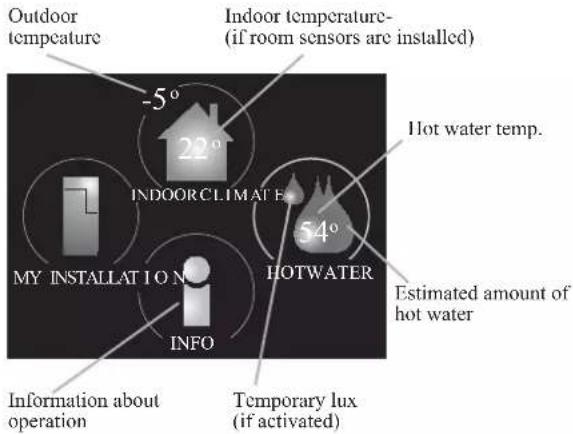
Menu 1 - INDOOR CLIMATE
Setting and scheduling the indoor climate. See information in the help menu or user manual.
Menu 2 - HOT WATER
Setting and scheduling hot water production. See information in the help menu or user manual.
This menu only appears if a water heater is installed in the system.
Menu 3 - INFO
Display of temperature and other operating information and access to the alarm log. See information in the help menu or user manual.
Menu 4 - MY INSTALLATION
Setting time, date, language, display, operating mode etc. See information in the help menu or user manual.
Menu 5 - SERVICE
Advanced settings. These settings are not available to the end user. The menu is made visible by pressing the Back button for 7 seconds in the top screen. See page 68 for details.
Symbols in the display
The following symbols can appear in the display during operation.
| Symbol Description | |
 | This symbol appears when there is information to be noticed in menu 3.1. |
 | These two symbols indicate whether the compressor in the outdoor unit or additional heat in the installation is blocked via controller.These functions will be blocked for example, when either of the operation mode is blocked in menu 4.2, when blocking of either function is scheduled in menu 4.9.5, or when an alarm for blocking the operation occurs.Blocking the compressor.Blocking additional heat. |
 | This symbol appears if periodic increase or lux mode for the hot water is activated. |
 | This symbol indicates if "holiday setting" is active in menu 4.7. |
 | This symbol indicates if the controller has contact with myUpway. |
 | This symbol indicates if cooling is active. |

flowchart
graph LR
    A["Window"] --> B["Menu number – marked sub menu"]
    B --> C["Symbol – main menu"]
    C --> D["Indoor Climate"]
    D --> E["temperature 25.0°"]
    D --> F["scheduling off"]
    D --> G["advanced"]
    H["My INSTALLATION"] --> I["INDOOR CLIMATE"]
    J["HOT WATER"] --> K["INFO"]
    L["Marked main menu"] --> M["Symbols – sub menus"]
    M --> N["Status information – sub menus"]
Operation
To move the cursor, turn the control knob to the left or the right. The marked position is brighter and/or has a light frame.
Selecting menu
To advance in the menu system select a main menu by marking it and then pressing the OK button. A new window opens with sub menus.
Select one of the sub menus by marking it and then pressing the OK button.
Selecting options

Alternative

In an options menu the current selected option is indicated by a green tick.
To select another option:
- Mark the applicable option. One of the options is pre-selected (white).

- Press the OK button to confirm the selected option.

The selected option has a green tick.
Setting a value
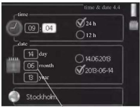
Values to be changed
To set a value:
- Mark the value you want to set using the control knob.
- Press the OK button. The background of the value becomes green, which means that you have accessed the setting mode.
- Turn the control knob to the right to increase the value and to the left to reduce the value.
- Press the OK button to confirm the value you have set. To change and return to the original value, press the Back button.
01
01
04
04
Use the virtual keyboard

In some menus where text may require entering, a virtual keyboard is available.

Depending on the menu, you can gain access to different character sets which you can select using the control knob. To change character table, press the Back button. If a menu only has one character set, the keyboard is displayed directly.
When you have finished writing, mark "OK" and press the OK button.
Scroll through the windows
A menu can consist of several windows. Turn the control knob to scroll between the windows.

Scroll through the windows in the start guide

-
Turn the control knob until one of the arrows in the top left corner (at the page number) has been marked.
-
Press the OK button to skip between the steps in the start guide.
Help menu
In many menus there is a symbol that indicates that extra help is available.
To access the help text:
- Use the control knob to select the help symbol.
- Press the OK button.
The help text often consists of several windows that you can scroll between using the control knob.
Menu list
"* Accessories are needed. ** Heat pump with cooling function required. 40"
| MENU RC-HY20 RC-HY40 | ||||
| 1 INDOOR CLIMATE | ||||
| 1.1 - temperature 1.1.1 heating | ✓ | ✓ | ||
| 1.1.2 cooling ** | ✓ | ✓ | ||
| 1.3 - scheduling 1.3.1 heating | ✓ | ✓ | ||
| 1.3.2 cooling ** | ✓ | ✓ | ||
| 1.9 - advanced 1.9.1 curve 1.9.1.1 | heating curve | ✓ | ✓ | |
| 1.9.1.2 cooling curve ** | ✓ | ✓ | ||
| 1.9.2 external adjustment | ✓ | ✓ | ||
| 1.9.3 min. flow line temp. 1.9.3 | 1 heating | ✓ | ✓ | |
| 1.9.3.2 cooling ** | ✓ | ✓ | ||
| 1.9.4 room sensor settings | ✓ | ✓ | ||
| 1.9.5 cooling settings * | ✓ | ✓ | ||
| 1.9.7 own curve 1.9.7.1 heating | ✓ | ✓ | ||
| 1.9.7.2 cooling ** | ✓ | ✓ | ||
| 1.9.8 point off set | ✓ | ✓ | ||
| 2 HOTWATER | ||||
| 2.1 temporary lux | ✓ | ✓ | ||
| 2.2 comfort mode | ✓ | ✓ | ||
| 2.3 scheduling | ✓ | ✓ | ||
| 2.9 advanced 2.9.1 periodic increase | ✓ | ✓ | ||
| 2.9.2 hot water recirc. * | ✓ | ✓ | ||
| 3 INFO | ||||
| 3.1 service info | ✓ | ✓ | ||
| 3.2 compressor info | ✓ | ✓ | ||
| 3.3 add. heat info | ✓ | ✓ | ||
| 3.4 alarm log | ✓ | ✓ | ||
| 3.5 indoor temp. log | ✓ | ✓ | ||
| 4. MY SYSTEM | ||||
| 4.1 plus functions 4.1.3 internet 4.1.3.1 myUpwayTM | ✓ | ✓ | ||
| 4.1.3.8 tcp/ip settings | ✓ | ✓ | ||
| 4.1.3.9 proxy settings | ✓ | ✓ | ||
| 4.1.5 SG Ready | ✓ | ✓ | ||
| 4.1.6 smart price adaptionTM | ✓ | ✓ | ||
| 4.1.8 smart energy sourceTM | 4.1.8.1 settings | - | ||
| 4.1.8.2 set. Price | - | |||
| 4.1.8.3 CO2 impact | - | |||
| 4.1.8.4 tariff periods, electricity | - | |||
| 4.1.8.6 tariff per, ext. shunt add | - | |||
| 4.1.8.7 tariff per, ext. step add | - | |||
| 4.2 op. mode | ✓ | ✓ | ||
| 4.3 my icons | ✓ | ✓ | ||
| 4.4 time & date | ✓ | ✓ | ||
"* Accessories are needed. ** Heat pump with cooling function required. 40"
| MENU RC-HY20 RC-HY40 | ||||
| 4.6 language | ✓ | ✓ | ||
| 4.7 holiday setting | ✓ | ✓ | ||
| 4.9 advanced 4.9.1 op. prioritisation | ✓ | ✓ | ||
| 4.9.2 auto mode setting | ✓ | ✓ | ||
| 4.9.3 degree minute setting | ✓ | ✓ | ||
| 4.9.4 factory setting user | ✓ | ✓ | ||
| 4.9.5 schedule blocking | ✓ | ✓ | ||
| 4.9.6 schedule silent mode | ✓ | ✓ | ||
| 5 SERVICE | ||||
| 5.1 operating settings 5.1.1 hot water settings * | ✓ | ✓ | ||
| 5.1.2 max flow line temperature | ✓ | |||
| 5.1.3 max diff flow line temp. | ✓ | |||
| 5.1.4 alarm actions | ✓ | |||
| 5.1.12 addition | ✓ | |||
| 5.1.14 flow set climate system | ✓ | |||
| 5.1.22 heat pump testing | ✓ | |||
| 5.1.23 compressor curve | ✓ | |||
| 5.2 system settings 5.2.2 installed slaves | ✓ | ✓ | ||
| 5.2.3 docking | ✓ | |||
| ✓ | ||||
| 5.2.4 accessories | controlled add. heat * | - | ||
| 5.3.3 extra climate system * | - | |||
| 5.3.6 step controlled add. Heat | - | |||
| 5.3.8 hot water comfort * | - | |||
| 5.3.20 flow sensor* | - | |||
| 5.4 soft in/outputs | ✓ | ✓ | ||
| 5.5 factory setting service | ✓ | ✓ | ||
| 5.6 forced control | ✓ | ✓ | ||
| 5.7 start guide | ✓ | ✓ | ||
| 5.8 quick start | ✓ | ✓ | ||
| 5.9 floor drying function | ✓ | ✓ | ||
| 5.10 change log | ✓ | ✓ | ||
| 5.11 slave settings 5.11.1 EB101 | 5.11.1.1 heat pump | ✓ | ✓ | |
| 5.11.1.2 charge pump (GP12) | ✓ | ✓ | ||
| 5.11.2 EB102 | - | ✓ | ||
| 5.11.3 EB103 | - | ✓ | ||
| 5.11.4 EB104 | - | ✓ | ||
| 5.11.5 EB105 | - | ✓ | ||
| 5.11.6 EB106 | - | ✓ | ||
| 5.11.7 EB107 | - | ✓ | ||
| 5.11.8 EB108 | - | ✓ | ||
| 5.12 country | ✓ | ✓ | ||
Sub-menus
Menu SERVICE has orange text and is intended for the advanced user. This menu has several sub-menus.
Status information for the relevant menu can be found on the display to the right of the menus.
operating settings: Operating settings for the control module.
system settings: System settings for the control module, activating accessories etc.
soft in/outputs: Setting software controlled in and outputs on the input card (AA3) and terminal block (X2).
factory setting service: Total reset of all settings (including settings available to the user) to default values.
forced control: Forced control of the different components in the indoor module.
start guide: Manual start of the start guide which is run the first time when the control module is started.
quick start: Quick starting the compressor.
NOTE
Incorrect settings in the service menus can damage the installation.
Menu 5.1 - operating settings
Operating settings can be made for the control module in the sub menus.
Menu 5.1.1 - hot water settings
economy
Setting range start temp. economy: 5 - 55 °C
Factory setting start temp. economy: 42 °C
Setting range stop temp. economy: 5 - 60 °C
Factory setting stop temp. economy: 48 °C
normal
Setting range start temp. normal: 5 - 60 °C
Factory setting start temp. normal: 46 °C
Setting range stop temp. normal: 5 - 65 °C
Factory setting stop temp. normal: 50 °C
luxury
Setting range start temp. lux: 5 - 70 °C
Factory setting start temp. lux: 49 °C
Setting range stop temp. lux: 5 - 70 °C
Factory setting stop temp. lux: 53 °C
stop temp. per. increase
Setting range: 55 – 70 °C
Factory setting: 55 °C
charge method
Setting range: target temp, delta temp
Default value: delta temp
Here you set the start and stop temperature of the hot water for the different comfort options in menu 2.2 as well as the stop temperature for periodic increase in menu 2.9.1.
The charge method for hot water mode is selected here. "delta temp" is recommended for heaters with charge coil, "target temp" for heaters with domestic coil.
Menu 5.1.2 - max flow line temperature
climate system
Setting range: 5 - 70 °C
Default value: 60 °C
Set the maximum supply temperature for the climate system here. If the installation has more than one climate system, individual maximum supply temperatures can be set for each system. Climate systems 2 – 8 cannot be set to a higher max supply temperature than climate system 1.
CAUTION
Underfloor heating systems are normally max flow line temperature set between 35 and 45°C.
Be careful not to cause low temperature burn if it is set at 35^ C or higher.
Check the max floor temperature with your floor supplier.
Menu 5.1.3 - max diff flow line temp.
max diff compressor
Setting range: 1 - 25 °C
Default value: 10 °C
max diff addition
Setting range: 1 - 24 °C
Default value: 7 °C
Here you set the maximum permitted difference between the calculated and actual supply temperature during compressor mode and add. heat mode. Max diff. additional heat can never exceed max diff. compressor
max diff compressor
When the current supply temperature deviates from the set value compared to that calculated, the heat pump is forced to stop irrespective of the degreeminute value.
If the current supply temperature exceeds the calculated flow temperature plus the set value, the degree minute value is set to 0. The compressor in the heat pump stops when there is only a heating demand.
max diff addition
If "addition" is selected and activated in menu 4.2 and the present supply temp exceeds the calculated temperature plus the set value, the additional heat is forced to stop.
Menu 5.1.4 - alarm actions
Select how to control the heat pump in the event of an alarm. You can choose to stop producing hot water and/or reduce the room temperature.
CAUTION
If no alarm action is selected, it can result in higher energy consumption in the event of an alarm.
Menu 5.1.12 - addition
add type: step controlled
max step
Setting range (binary stepping deactivated): 0 - 3
Setting range (binary stepping activated): 0 - 7
Default value: 3
fuse size
Setting range: 1 - 200 A
Factory setting: 16 A
You can set the maximum number of permitted additional heat steps, if there is internal additional heat in the tank (only accessible if the additional heat is positioned after QN10), whether binary stepping is to be used and the size of the fuse.
prioritised additional heat
Setting range: on/off
Factory setting: off
minimum running time
Setting range: 0 – 48 h
Default value: 12 h
min temp.
Setting range: 5 – 90 °C
Default value: 55 °C
mixing valve amplifier
Setting range: 0.1 - 10.0
Default value: 1.0
mixing valve step delay
Setting range: 10 - 300 s
Default values: 30 s
fuse size
Setting range: 1 - 200 A
Factory setting: 16 A
transformation ratio
Setting range: 300 - 3000
Factory setting: 300
Select this option if shunt controlled additional heat is connected.
Set when the addition is to start, the minimum run time and the minimum temperature for external addition with shunt here. External addition with shunt is for example a wood/oil/gas/pellet boiler.
You can set shunt valve amplification and shunt valve waiting time.
Selecting "prioritised additional heat" uses the heat from the external additional heat instead of the heat pump.
The shunt valve is regulated as long as heat is available, otherwise the shunt valve is closed.
TIP
See the accessory installation instructions for function description.
Menu 5.1.14 - flow set. climate system
presettings
Setting range: radiator, fl oor heat., rad. + fl oor heat.
Default value: radiator
Setting range DOT: -40.0 – 20.0 °C
The factory setting of DOT value depends on the country that has been given for the product's location.
The example below refers to Sweden.
Factory setting DOT: -20.0 °C
own setting
Setting range dT at DOT: 0.0 - 25.0
Factory setting dT at DOT: 10.0
Setting range DOT: -40.0 - 20.0 °C
Factory setting DOT: -20.0 °C
Select the type of heating distribution system.
dT at DOT is the difference in degrees between flow and return temperatures at dimensioned outdoor temperature.
Menu 5.1.22 - heat pump testing
NOTE
This menu is intended for testing heat pump according to different standards.
Use of this menu for other reasons may result in your installation not functioning as intended.
This menu contains several sub-menus, one for each standard.
Menu 5.1.23 - compressor curve
Set whether the compressor in the heat pump should work to a particular curve under specific requirements or if it should work to predefined curves.
You can set a curve for each operation mode (heat, hot water, coolingetc.) by unticking "auto", turning the control knob until a temperature is marked and pressing OK. You can set at what temperature max- min frequencies will occur.
This menu consists of several windows (one for each operation mode). Use the navigation arrow in the top left corner to change between the windows.
Menu 5.2 - system settings
Make different system settings for your installation here, e.g. activate the connected heat pump and which accessories are installed.
Menu 5.2.2 - installed heat pump
If a heat pump is connected to the master installation, set it here.
For RC-HY40, you can set slave unit to be connected.
There are two ways of activating connected slaves. You can either mark the alternative in the list or use the automatic function "search installed slaves".
search installed slaves
Mark "search installed slaves" and press the OK button to automatically find connected slaves for the master heat pump.
Menu 5.2.3 - docking (RC-HY 40 only)
Enter how your system is docked regarding pipes, for example to hot water heating and heating the building.
This menu has a docking memory which means that the control system remembers how a particular reversing valve is docked and automatically enters the correct docking the next time you use the same reversing valve.
Workspace for dockingSlave (heat pump)
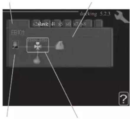
Marking frameCompressor
Slave: Here you select for which heat pump the docking setting is to be made.
Compressor: Select if the compressor in the heat pump is blocked (factory setting), or standard (docked for example to pool heating, hot water charging and heating the building).
Marking frame: Move around the marking frame using the control knob. Use the OK button to select what you want to change and to confirm setting in the options box that appears to the right.
Workspace for docking: The system docking is drawn here.
| Symbol | Description |
| Compressor (blocked) |
| Compressor (standard) |
| Reversing valves for hot water, cooling. The designations above the reversing valve indicate where it is electrically connected (EB101 = Slave 1, etc.). |
| Hot water charging |
| Heating (heating the building, includes any extra climate system) |
| Cooling |
Menu 5.2.4 - accessories
Set which accessories are installed on the installation here.
If the water heater is connected, hot water charging must be activated here.
Menu 5.3 - accessory settings
The operating settings for accessories that are installed and activated are made in the sub-menus for this.
Menu 5.3.2 - shunt controlled add. Heat
prioritised additional heat
Setting range: on/off
Factory setting: off
start diff additional heat
Setting range: 0 - 2000 GM
Default values: 400 GM
minimum running time
Setting range: 0 – 48 h
Default value: 12 h
min temp.
Setting range: 5 – 90 °C
Default value: 55 °C
mixing valve amplifier
Setting range: 0.1 - 10.0
Default value: 1.0
mixing valve step delay
Setting range: 10 - 300 s
Default values: 30 s
Set when the addition is to start, the minimum run time and the minimum temperature for external addition with shunt here.
External addition with shunt is for example a wood/oil/gas/pellet boiler.
You can set shunt valve amplification and shunt valve waiting time.
Selecting "prioritised additional heat" uses the heat from the external additional heat instead of the heat pump.
The shunt valve is regulated as long as heat is available, otherwise the shunt valve is closed.
See the accessory installation instructions for function description.
Menu 5.3.3 - extra climate system
use in heating mode
Setting range: on/off
Factory setting: on
use in cooling mode
Setting range: on/off
Factory setting: off
mixing valve amplifier
Setting range: 0.1 - 10.0
Default value: 1.0
mixing valve step delay
Setting range: 10 - 300 s
Default values: 30 s
Here you select which climate system (2 - 8) you wish to set.
In the next menu you can make settings for the climate system
that you have selected. If this function is activated, you can set "cooling flow temp. at +20°C" and "cooling flow temp. at +40°C" for each climate system where the function is activated.
CAUTION
This setting option only appears if "cooling permitted" is activated in menu 5.11.1.1.
The shunt amplification and shunt waiting time for the different extra climate systems that are installed are also set here.
See the accessory installation instructions for function description.
Menu 5.3.6 - step controlled add. heat
start addition
Setting range: 0 - 2000 GM
Default values: 400 GM
diff. between additional steps
Setting range: 0 - 1000 GM
Default values: 30 GM
max step
Setting range
(binary stepping deactivated): 0 - 3
Setting range
(binary stepping activated): 0 - 7
Default value: 3
binary stepping
Setting range: on/off
Factory setting: off
Make settings for step controlled addition here. Step controlled addition is for example an external electric boiler.
It is possible, for example, to select when the additional heat is to start, to set the maximum number of permitted steps and whether binary stepping is to be used.
When binary stepping is deactivated (off), the settings refer to linear stepping.
See the accessory installation instructions for function description.
Menu 5.3.8 - hot water comfort
activating imm heater
Setting range: on/off
Factory setting: off
activ. imm heat in heat mode
Setting range: on/off
Factory setting: off
activating the mixing valve
Setting range: on/off
Factory setting: off
outgoing hot water
Setting range: 40 – 65 °C
Default value: 55 °C
mixing valve amplifier
Setting range: 0.1 - 10.0
Default value: 1.0
mixing valve step delay
Setting range: 10 - 300 s
Default values: 30 s
Make settings for the hot water comfort here.
See the accessory installation instructions for function description.
activating imm heater: The immersion heater is activated here if installed in the water heater.
activ. imm heat in heat mode: Activate here whether the immersion heater in the tank (required if the alternative above is activated) will be permitted to charge hot water, if the compressors in the heat pump prioritise heating.
activating the mixing valve: Activate here whether a mixer valve for limiting the temperature of hot water from the water heater is installed.
If this alternative has been activated, you can set the outgoing hot water temperature, shunt amplification and shunt waiting time for the mixer valve.
outgoing hot water: Set the temperature at which the mixing valve is to restrict hot water from the water heater.
See the accessory installation instructions for function description.
Menu 5.3.20 - flow sensor
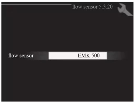
flow sensor
Setting option: EMK 500, EMK 310 / 300, EMK 150
Factory setting: EMK 500
Here you select which flow sensor is used for the energy measurement.
Menu 5.4 - soft in/outputs
You can set the function of in/output for each terminal (AUX1-6 and output).
Position of the terminal depends on the type of controller.
RC-HY20: port 11-18 on X2 terminal (AUX1-6), X4 terminal on AA2 board (output)
RC-HY40: port 9-14 on terminal X6 and port 1-4 on X2 terminal on AA3 board (AUX1-6), X7 terminal on AA3 board (output)
Menu 5.5 - factory setting service
All settings can be reset (including settings available to the user) to default values here.
NOTE
When resetting, the start guide is displayed the next time the control module is restarted.
Menu 5.6 - forced control
You can force control the different components in the control module and any connected accessories here.
Menu 5.7 - start guide
When the control module is started for the first time the start guide starts automatically. Start it manually here.
See page 25 for more information about the start guide.
Menu 5.8 - quick start
It is possible to start the compressor from here.
CAUTION
There must be a heating or hot water demand to start the compressor.
CAUTION
Do not quick start the compressor too many times over a short period of time as this may damage the compressor and its surrounding equipment.
Menu 5.9 - floor drying function
length of period 1 - 7
Setting range: 0 - 30 days
Factory setting, period 1 – 3, 5 – 7: 2 days
Factory setting, period 4: 3 days
temp. period 1 – 7
Setting range: 15 - 70 °C
Default value:
| temp. period 1 | 20 °C |
| temp. period 2 | 30 °C |
| temp. period 3 | 40 °C |
| temp. period 4 | 45 C |
| temp. period 5 | 40 °C |
| temp. period 6 | 30 °C |
| temp. period 7 | 20 °C |
Set the function for under floor drying here.
You can set up to seven period times with different calculated flow temperatures. If less than seven periods
are to be used, set the remaining period times to 0 days.
Mark the active window to activate the underfloor drying function. A counter at the bottom shows the number of days the function has been active.
TIP
If operating mode "add. heat only" is to be used, select it in menu 4.2.
Menu 5.10 - change log
Read off any previous changes to the control system here.
The date, time and ID no. (unique to certain settings) and the new set value is shown for every change.
NOTE
The change log is saved at restart and remains unchanged after factory setting.
Menu 5.11 - heat pump settings
Settings for installed heat pump can be made in the submenus.
Menu 5.11.1 - EB101 - EB108
Make settings specifically for the installed heat pump and charge pump here.
For RC-HY40, it is possible to connect up to 8 heat pumps.
Menu 5.11.1.1 - heat pump
Make settings for the installed heat pump here. To see what settings you can make, see installation manual for the heat pump.
Menu 5.11.1.2 - charge pump (GP12)
op. mode
Heating/cooling
Setting range: auto / intermittent
Default value: auto
Set the operating mode for the charge pump here.
auto: The charge pump runs according to the current operating mode for SMO 20.
intermittent: The charge pump starts and stops 20 seconds before and after the compressor in the heat pump.
speed during operation heating, hot water, cooling
Setting range: auto / manual
Default value: auto
Manual setting
Setting range: 1 - 100 %
Default values: 70 %
speed in wait mode
Setting range: 1 - 100 %
Default values: 30 %
max. allowed speed
Setting range: 80 - 100 %
Default values: 100 %
Set the speed at which the charge pump is to operate in the present operating mode. Select "auto" if the speed of the charge pump is to be regulated automatically (factory setting) for optimal operation.
If "auto" is activated for heating operation, you can also make the setting "max. allowed speed" which restricts the charge pump and does not allow it to run at a higher speed than the set value.
For manual operation of the charge pump deactivate "auto" for the current operating mode and set the value to between 1 and 100 % (the previously set value for "max. allowed speed" no longer applies).
Speed in standby mode (only used if "auto" has been selected for "Operating mode") means the charge pump operates at the set speed during the time when there is neither a need for compressor operation nor additional heat.
5.12 - country
Select here where the product was installed. This allows access to country specific settings in your product.
Language settings can be made regardless of this selection.
NOTE
This option locks after 24 hours, restart of display or program updating.
Service
Service actions
NOTE
Servicing should only be carried out by persons with the necessary expertise.
When replacing components on the system, only genuine replacement parts may be used.
NOTE
If an electrical connection has been disconnected and is connected, ground must be checked using a suitable multimeter.
Maintenance
General inspection
Check the following:
- Condition of casing.
- Electrical connections.
- Alarm log.
Correct any fault before continuing.
Climate system
Check the following:
- Climate system start and stop temperature.
- Heating curve settings.
- Function of the room sensor (if installed).
- System pressure.
- Flow and return temperature. The difference must be 5-10 °C.
Correct any fault before continuing.
Emergency mode
NOTE
Switch (SF1) must not be put into mode "I" or △ before the installation is filled with water. The compressor in the heat pump can be damaged.
Emergency mode is used in event of operational interference and in conjunction with service. Hot water is not produced in emergency mode.
Emergency mode is activated by setting switch (SF1) in mode "△". This means that:
■ The status lamp illuminates yellow.
■ The display is not lit and the control computer is not connected.
■ Hot water is not produced.
■ The compressors are switched off. Charge pump (EB101-GP12) is running.
■ The heating medium pump is active.
■ The emergency mode relay (K1) is active.
External additional heat is active if it is connected to the emergency mode relay (K1, terminal block X1).
Ensure that the heating medium circulates through the external additional heat.
Temperature sensor data
| Temperature (°C) | Resistance (kOhm) | Voltage (VDC) |
| -40 351.0 3.256 | ||
| -35 251.6 3.240 | ||
| -30 182.5 3.218 | ||
| -25 133.8 3.189 | ||
| -20 99.22 3.150 | ||
| -15 74.32 3.105 | ||
| -10 56.20 3.047 | ||
| -5 42.89 2.976 | ||
| 0 33.02 2.889 | ||
| 5 25.61 2.789 | ||
| 10 20.02 2.673 | ||
| 15 15.77 2.541 | ||
| 20 12.51 2.399 | ||
| 25 10.00 2.245 | ||
| 30 8.045 2.083 | ||
| 35 6.514 1.916 | ||
| 40 5.306 1.752 | ||
| 45 4.348 1.587 | ||
| 50 3.583 1.426 | ||
| 55 2.968 1.278 | ||
| 60 2.467 1.136 | ||
| 65 2.068 1.007 | ||
| 70 1.739 0.891 | ||
| 75 1.469 0.785 | ||
| 80 1.246 0.691 | ||
| 85 1.061 0.607 | ||
| 90 0.908 0.533 | ||
| 95 0.779 0.469 | ||
| 100 0.672 0.414 |
USB service outlet
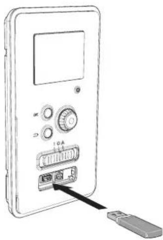
RC-HY20/40 is equipped with a USB socket in the display unit. This USB socket can be used to connect a USB memory to update the software, save logged information and handle the settings in RC-HY20/40.

When a USB memory is connected a new menu (menu 7) appears in the display.
Menu 7.1 - update firmware
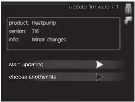
This allows you to update the software in RC-HY20/40.
NOTE
For the following functions to work the USB memory must contain files with software for RC-HY20/40.
This information states which product the software is intended for, the software version and general information about them. If you wish to select another file than the one selected, the correct file can be selected by "choose another file".
start updating
Select "start updating" if you want to start the update.
You are asked whether you really want to update the software. Respond "yes" to continue or "no" to undo.
If you responded "yes" to the previous question the update starts and you can now follow the progress of the update on the display. When the update is complete RC-HY20/40 restarts.
NOTE
A software update does not reset the menu settings in RC-HY20/40.
NOTE
If the update is interrupted before it is complete (for example power cut etc.) the software can be reset to the previous version if the OK button is kept pressing during start up until the green lamp starts to illuminate (takes about 10 seconds).
choose another file
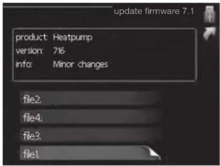
Select "choose another file" if you do not want to use the suggested software. When you scroll through the files, information about the marked software is shown in a fact box just as before. When you have selected a file with the OK button you will return to the previous page (menu 7.1) where you can choose to start the update.
Menu 7.2 - logging

Setting range: 1 s - 60 min
Factory setting range: 5 s
You can set the interval of the log data storage and start saving the log data on the USB memory.
- Set the desired interval between loggings.
- Tick "activated".
- The present values from RC-HY20/40 are saved in a file in the USB memory at the set interval until "activated" is unticked.
NOTE
Untick "activated" before removing the USB memory. Menu 7.3 - manage settings
Menu 7.3 - manage settings

Here you can manage (save as or retrieve from) all the menu settings (user and service menus) in RC-HY20/40 with a USB memory.
Via "save settings" you save the menu settings to the USB memory in order to restore them later or to copy the settings to another RC-HY20/40.
NOTE
When you save the menu settings to the USB memory you replace any previously saved settings on the USB memory.
Via "recover settings" you reset all menu settings from the USB memory.
NOTE
Reset of the menu settings from the USB memory cannot be undone.
Disturbance in comfort
In most cases, the control module notes a malfunction and indicates this with alarms and shows instructions to rectify it in the display. See "Manage alarm" for in- formation about managing alarms. If the malfunction does not appear in the display, or if the display is not lit, the following troubleshooting guide can be used.
Manage alarm

In the event of an alarm, some kind of malfunction has occurred, which is indicated by the status lamp changing from green continuously to red continuously. In addition, an alarm bell appears in the information window.
Alarm
In the event of an alarm with a red status lamp a malfunction has occurred that the heat pump and/or control module cannot remedy itself. In the display, by turning the control knob and pressing the OK button, you can see the type of alarm it is and reset it. You can also choose to set the installation to aid mode.
info / action Here you can read what the alarm means and receive tips on what you can do to correct the problem that caused the alarm.
reset alarm In most cases it is enough to select "reset alarm" to correct the problem that caused the alarm. If a green light illuminates after selecting "reset alarm" the alarm has been remedied. If a red light is still visible and a menu called "alarm" is visible in the display, the problem that caused the alarm remains. If the alarm disappears and then returns, see the troubleshooting section (page 64 and 65).
aid mode "aid mode" is a type of emergency mode. This means that the installation produces heat and/or hot water despite there being some kind of problem. This can mean that the heat pump's compressor is not running. In this case any electrical addition produces heat and/or hot water.
NOTE
To select aid mode an alarm action must be selected in the menu 5.1.4.
CAUTION
Selecting "aid mode" is not the same as correcting the problem that caused the alarm. The status lamp will therefore continue to be red.
Troubleshooting
If the operational interference is not shown in the display the following tips can be used:
Basic actions
Start by checking the following possible fault sources:
■ The switch's (SF1) position.
■ Group and main fuses of the accommodation.
■ The property's earth circuit breaker.
■ The control module's miniature circuit breaker (FA1).
Low hot water temperature or a lack of hot water
This part of the fault-tracing chapter only applies if the water heater is installed in the system.
■ Closed or choked fi lling valve for the hot water heater.
- Open the valve.
■ Mixing valve (if there is one installed) set too low.
- Adjust the mixer valve.
■ Control module in incorrect operating mode.
- If mode "manual" is selected, select "addition".
■ Large hot water consumption.
- Wait until the hot water has heated up. Temporarily increased hot water capacity (temporary lux) can be activated in menu 2.1.
■ Too low hot water setting.
- Enter menu 2.2 and select a higher comfort mode.
■ Too low or no operating prioritisation of hot water.
- Enter menu 4.9.1 and increase the time for when hot water is to be prioritised.
Low room temperature
■ Closed thermostats in several rooms.
- Set the thermostats to max, in as many rooms as possible. Adjust the room temperature via menu 1.1, instead of choking the thermostats.
■ Control module in incorrect operating mode.
— Enter menu 4.2. If mode "auto" is selected, select a higher value on "stop heating" in menu 4.9.2.
- If mode "manual" is selected, select "heating". If this is not enough, select "addition".
■ Too low set value on the automatic heating control.
- Enter menu 1.1 "temperature" and adjust the offset heating curve up. If the room temperature is only low in cold weather the curve slope in menu 1.9.1 "heating curve" needs adjusting up.
■ Too low or no operating prioritisation of heat.
- Enter menu 4.9.1 and increase the time for when heating is to be prioritised.
■ "Holiday mode" activated in menu 4.7.
- Enter menu 4.7 and select "Off".
■ External switch for changing the room heating activated.
- Check any external switches.
■ Air in the climate system.
- Vent the climate system.
■ Closed valves to the climate system.
- Open the valves.
■ Incorrectly adjusted flow across the heat pump.
- Check whether alarm high condenser in (163) or high condenser out (162) is in the alarm log. Follow the instructions for adjusting charge flow.
High room temperature
■ Too high set value on the automatic heating control.
- Enter menu 1.1 (temperature) and reduce the offset heating curve. If the room temperature is only high in cold weather the curve slope in menu 1.9.1 "heating curve" needs adjusting down.
■ External switch for changing the room heating activated.
- Check any external switches.
Low system pressure
■ Not enough water in the climate system.
- Top up the water in the climate system.
The compressor does not start
■ There is no heating requirement.
- The heat pump does not call on heating nor hot water.
■ Temperature conditions tripped.
- Wait until the temperature condition has been re-set.
■ Minimum time between compressor starts has not been reached.
- Wait 30 minutes and check if the compressor has started.
■ Alarm tripped.
– Follow the display instructions.
Additional heating only
If you are unsuccessful in rectifying the fault and are unable to heat the house, you can, whilst waiting for assistance, continue running the heat pump in "add. heat only". This means that additional heating only is used to heat the house.
Set the installation to additional heat mode
- Go to menu 4.2 op. mode.
- Mark "add. heat only" using the control knob and then press OK button.
Return to the main menus by pressing the Back button.
CAUTION
When commissioning without MTH air/water heat pump an alarm communication error may appear in the display.
The alarm is reset if the relevant heat pump is deactivated in menu 5.2.2 ("installed heat pump").
Alarm list
| Alarm nr. | Alarm text on the display | Description May be due to | |
| 157 Low | lp cooling Protection against freezing in water HX during cooling operation | ■ Low/no water flow | |
| 162 High | condenser out temperature | Too high temperature out from the condenser. Self-resetting. | ■ Low flow during heating operation■ Too high set temperatures |
| 163 High | condenser in temperature | Too high temperature into the condenser. Self-resetting. | ■ Temperature generated by another heat source |
| 183 Defrosting in progress Not an alarm, but an operating status. ■ Set when the heat pump runs the defrosting procedure | |||
| 220 High | pressure alarm BP4 has been above 4,15MPa 5 times within 60 minutes. | ■ Insuffi cient air circulation or blocked heat exchanger■ Expansion valve not correctly connected■ Service valve closed■ Defective control board in FDCW■ Low or no flow during heating operation■ Defective circulation pump■ Defective fuse, F(4A) | |
| 221 Low | pressure alarm Tool low value on the low pressure sensor 3 times within 60 minutes | ■ Open circuit or short circuit on input for low pressure sensor■ Defective low pressure sensor■ Defective control board in FDCW■ Open circuit or short circuit on input for suction gas sensor (Tho-S)■ Defective suction gas sensor (Tho-S) | |
| 223 Com | fl t from the heat pump | Communication between the control board and the communication board is interrupted. There must | ■ Any circuit breakers for FDCW off■ Incorrect cable routing |
| 224 Fan | alarm from heat pump | Deviations in the fan speed in FDCW. ■ The fan | cannot rotate freely■ Defective control board in FDCW■ Defective fan motor■ Control board in FDCW dirty■ Fuse (F2) blown |
| 228 | Failed defrosting | 10 aborted defrost due to alarm: 418,419 or 343 | ■ Too low water flow■ Too low return temperatur |
| 230 Hot gas alarm | Temperature deviation on the hot gas sensor (Tho-D) twice within 60 minutes or for 60 minutes continuously. | ■ Sensor does not work (see section "Ambient temperature sensor")■ Insuffi cient air circulation or heat exchanger■ Blocked■ If the fault persists during cooling, there may be an insufficient amount of refrigerant.■ Defective control board in FDCW | |
| 261 High | HWX temp Temperature deviation on the heat exchanger sensor (Tho-R1/R2) fi ve times within 60 minutes or for 60 minutes continuously. | ■ Sensor does not work (see section "Disturbances in comfort")■ Insuffi cient air circulation or blocked heat exchanger■ Defective control board in FDCW■ Too much refrigerant | |
| 262 Inv. err. When IPM (Intelligent power module) displays FO-signal (Fault Output) fi ve times during a 60-minute period. | Can occur when 15V power supply to the inverter PCB is unstable. | ||
| 263 Inv. err. Voltage from the inverter outside the parameters four times within 30 minutes. | ■ Incoming power supply interference■ Service valve closed■ Insuffi cient amount of refrigerant■ Compressor fault■ Defective circuit board in FDCW | ||
| 264 Communication error with inverter. | Communication between circuit board for inverter and control board broken. | ■ Open circuit in connection between boards■ Defective low pressure sensor■ Defective circuit board for inverter in FDCW■ Defective control board in FDCW | |
| 265 Inv. err. Continuous deviation on power transistor for 15 minutes. | ■ Defective fan motor■ Defective circuit board in FDCW | ||
| 266 Low refrig Insuffi cient refrigerant is detected upon star-up cooling mode. | ■ Service valve closed■ Loose connection sensor (BT15, BT3)■ Defective sensor (BT15, BT13)■ Too little refrigerant | ||
| 267 Inv. err. Failed start for compressor ■ Defective circuit board in FDCW | ■ Defective control board in FDCW■ Compressor fault | ||
| 268 Inv. err. Overcurrent, Inverter A/F module ■ Sudden power failure | |||
| 271 Lw otd tmp Temperature of BT28 below the value that permits operation | ■ Cold weather conditions■ Sensor fault | ||
| 272 High otd tmp Temperature of BT28 above the value that permits operation | ■ Warm weather conditions■ Sensor fault | ||
| 277 Sensor fault from heat pump | Sensor fault, heat exchanger in FDCW(Tho-R). | ■ Open circuit or short circuit on sensor input■ Sensor does not work (see section "Disturbances in comfort")■ Defective control board in FDCW | |
| 278 Sensor fault from heat pump | Sensor fault, outdoor temperature sensor in FDCW (Tho-A). | ■ Open circuit or short circuit on sensor input■ Sensor does not work (see section "Disturbances in comfort")■ Defective control board in FDCW | |
| 279 Sensor fault from heat pump | Sensor fault, hot gas in FDCW (Tho-D). ■ Open | circuit or short circuit on sensor input■ Sensor does not work (see section "Disturbances in comfort")■ Defective control board in FDCW | |
| 280 Sensor fault from heat pump | Sensor fault, suction gas in FDCW (Tho-S) ■ Open | circuit or short circuit on sensor input■ Sensor does not work (see section "Disturbances in comfort")■ Service valve closed■ Defective control board in FDCW | |
| 281 Sensor fault from heat pump | Sensor fault, low pressure transmitter in FDCW. | ■ Open circuit or short circuit on sensor input■ Sensor does not work (see section "Disturbances in comfort")■ Service valve closed■ Defective control board in FDCW■ Fault in the refrigerant circuit | |
| 294 Incompatible heat pump Heat pump and indoor module do not work properly together due to technical parameters. | ■ Outdoor module and indoor module are not compatible. | ||
| 343 Low temp water out Low water out temperature during cooling or tank defrost operation | ■ Too low water flow■ Too low return temperatur | ||
| 347 Temp high press Temporary high pressure alarm ■ No/low water flow | ■ Air in water system | ||
| 403 Sensor fault from PCA 154 | Sensor fault, Sensor incoming water in indoor unit (BT3). | ■ Open circuit or short circuit on sensor input■ Sensor does not work (see section "Disturbances in comfort")■ Defective control board AA23 in indoor unit. | |
| 404 Sensor fault from PCA 154 | Sensor fault, Sensor high pressure heating/low pressure cooling in indoor unit (BP4). | ■ Open circuit or short circuit on sensor input■ Sensor does not work (see section "Disturbances in comfort")■ Defective control board AA23 in indoor unit. | |
| 412 Sensor fault from PCA 154 | Sensor fault, Sensor outgoing water in indoor unit (BT12). | ■ Open circuit or short circuit on sensor input■ Sensor does not work (see section "Disturbances in comfort")■ Defective control board AA23 in indoor unit. | |
| 415 Sensor fault from PCA 154 | Sensor fault, Sensor fluid pipe in indoor unit (BT15). | ■ Open circuit or short circuit on sensor input■ Sensor does not work (see section "Disturbances in comfort")■ Defective control board AA23 in indoor unit. | |
| 418 Low temp water out Anti-freeze protection water heat exchanger during defrost. | ■ Too low water flow | ||
| 419 Freeze prot. exch. defr. Anti-freeze protection water heat exchanger during defrost. | ■ Too low water return temperature | ||
Accessories
EMK300M
Part no. MCD291A013
EMK500M
Part no. MCD291A014
Charge pump CPD 11
Charge pump for heat pump
CPD 11-25M/65
Part no. MCD291A016
CPD 11-25M/75
Part no. MCD291A017
External electric additional heat ELK
These accessories may require accessories card AXC 30 (step controlled addition).
ELK 9M
Immersion heater
9 kW 3 x 400 V
Part no. MCD291A015
Hot water control
VST 05M
Reversing valve, Cu pipe ∅22
Max heat pump size 8 kW
Part no. MCD291A018
VST 11M
Reversing valve, Cu pipe ∅28
(Max recommended output, 17 kW)
Part no. MCD291A019
VST 20M
Reversing valve, Cu pipe ∅35
(Max recommended output, 40 kW)
Part no. MCD291A020
Reversing valve for cooling
VCC 05M
Part no. MCD291A021
VCC 11M
Part no. MCD291A022
Electrical model
MEL 1030M
Part no. MCD291A023
Anode
Anode for tank
Anode T300
Part no. MCD291A024
Anode T500
Part no. MCD291A025
Anode M300
Part no. MCD291A026
Anode M500
Part no. MCD291A027
Technical data
Dimensions and setting-out coordinates
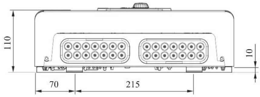
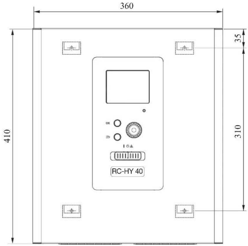
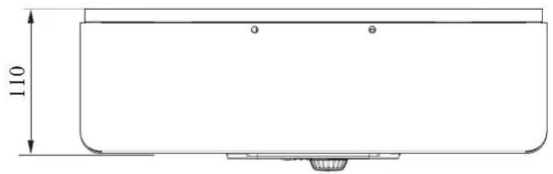
Electrical circuit diagram
HSB140
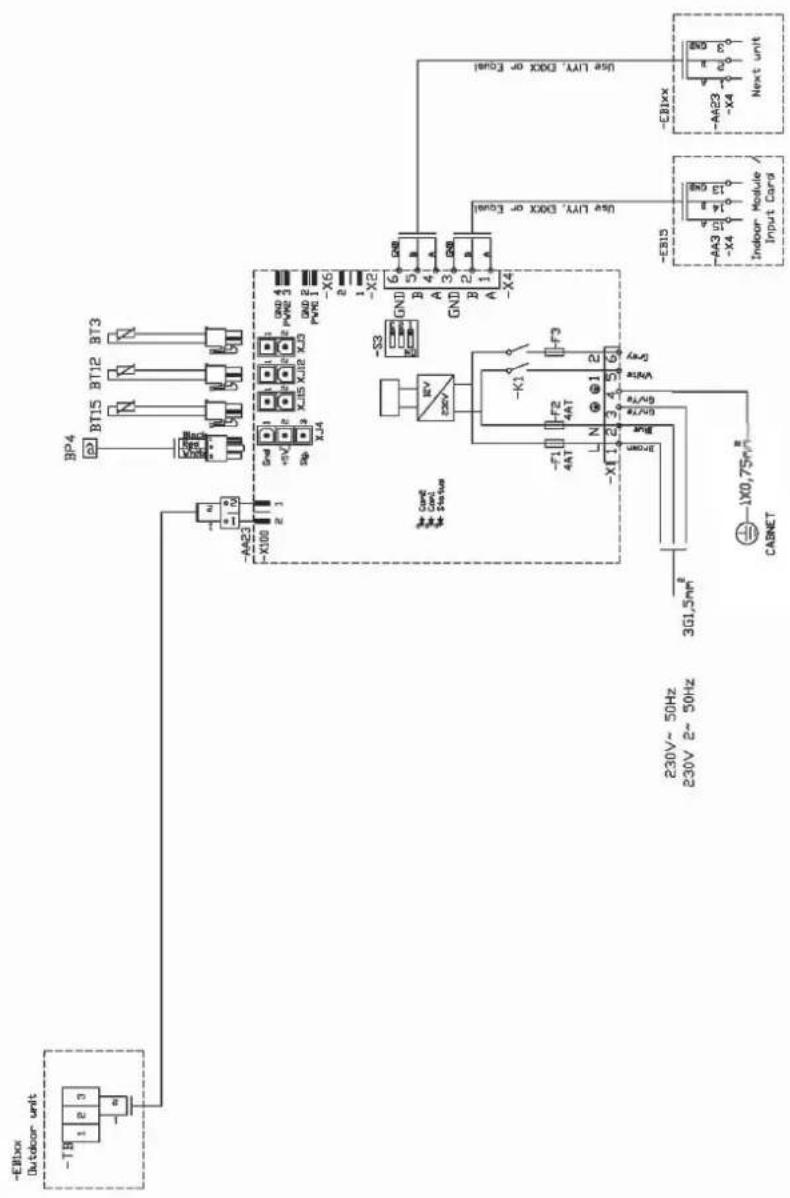
RC-HY20
sheet 1
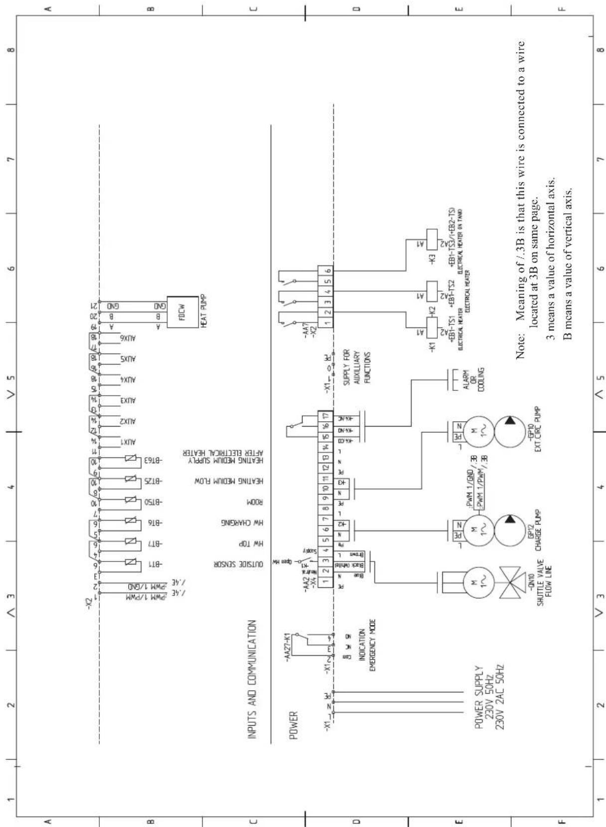
sheet 2
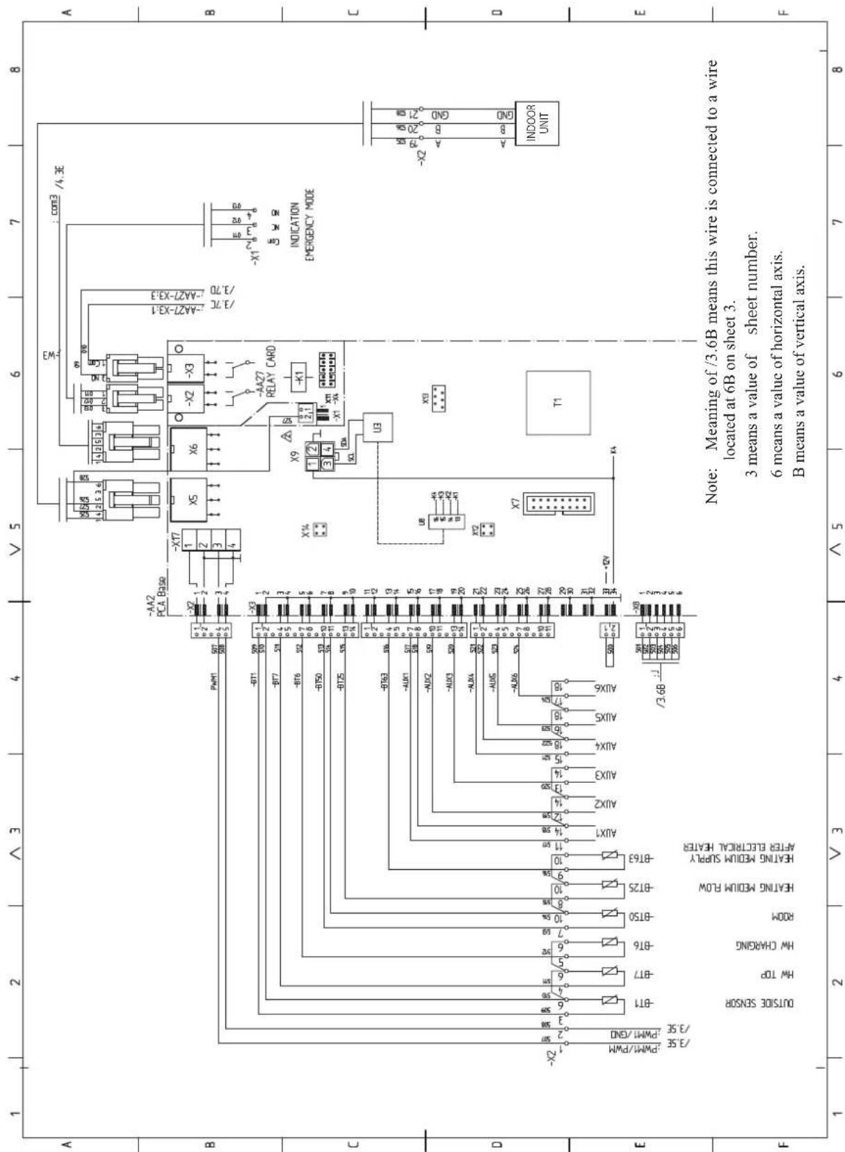
sheet 3

sheet 4

RC-HY40
sheet 1

sheet 2
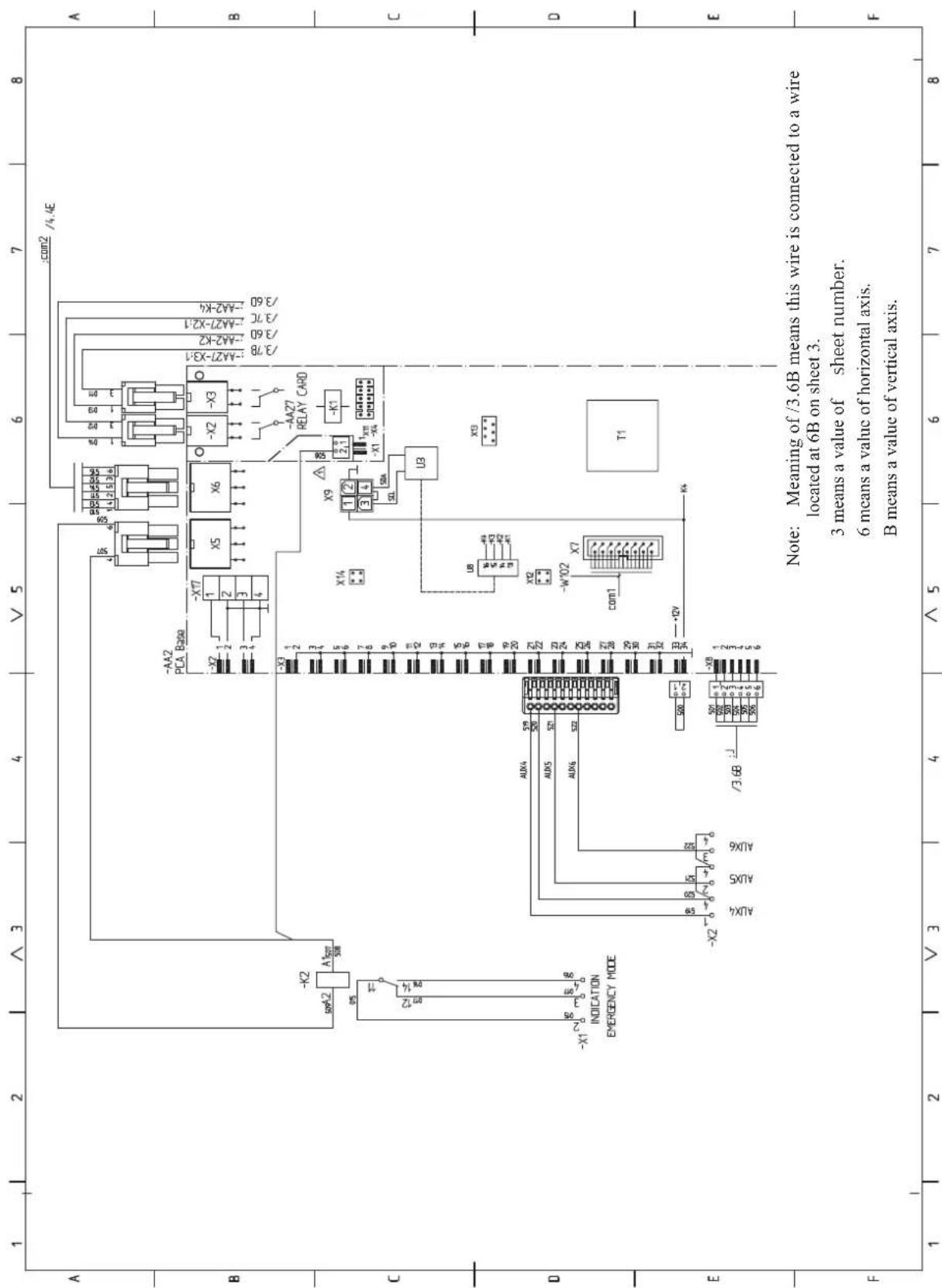
sheet 3
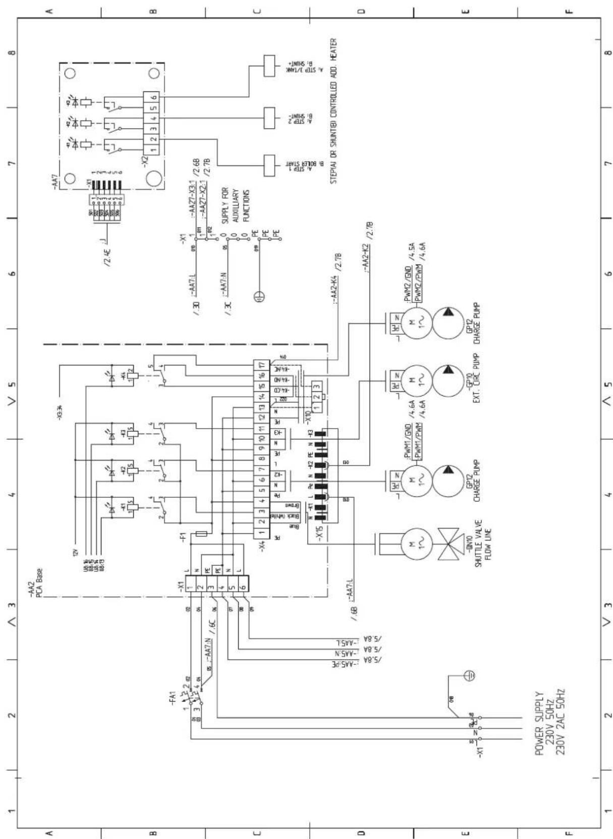
sheet 4
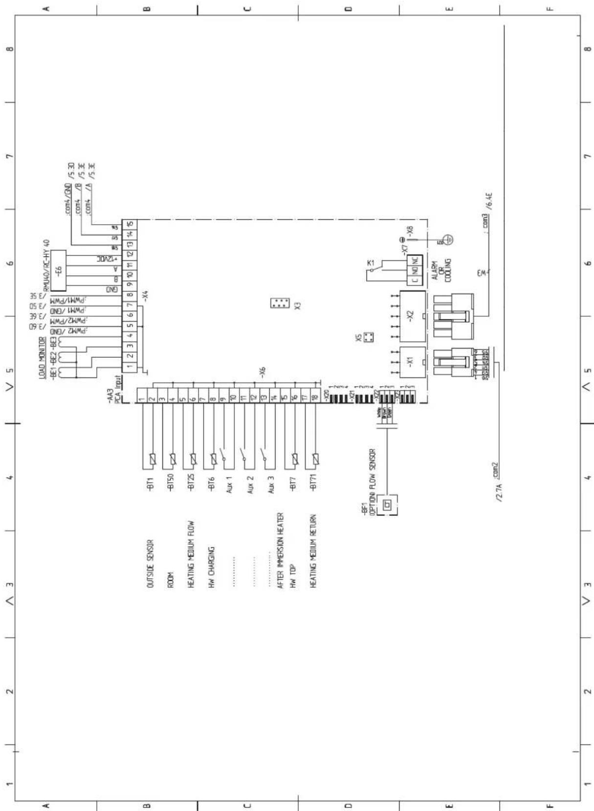
sheet 5

sheet 6
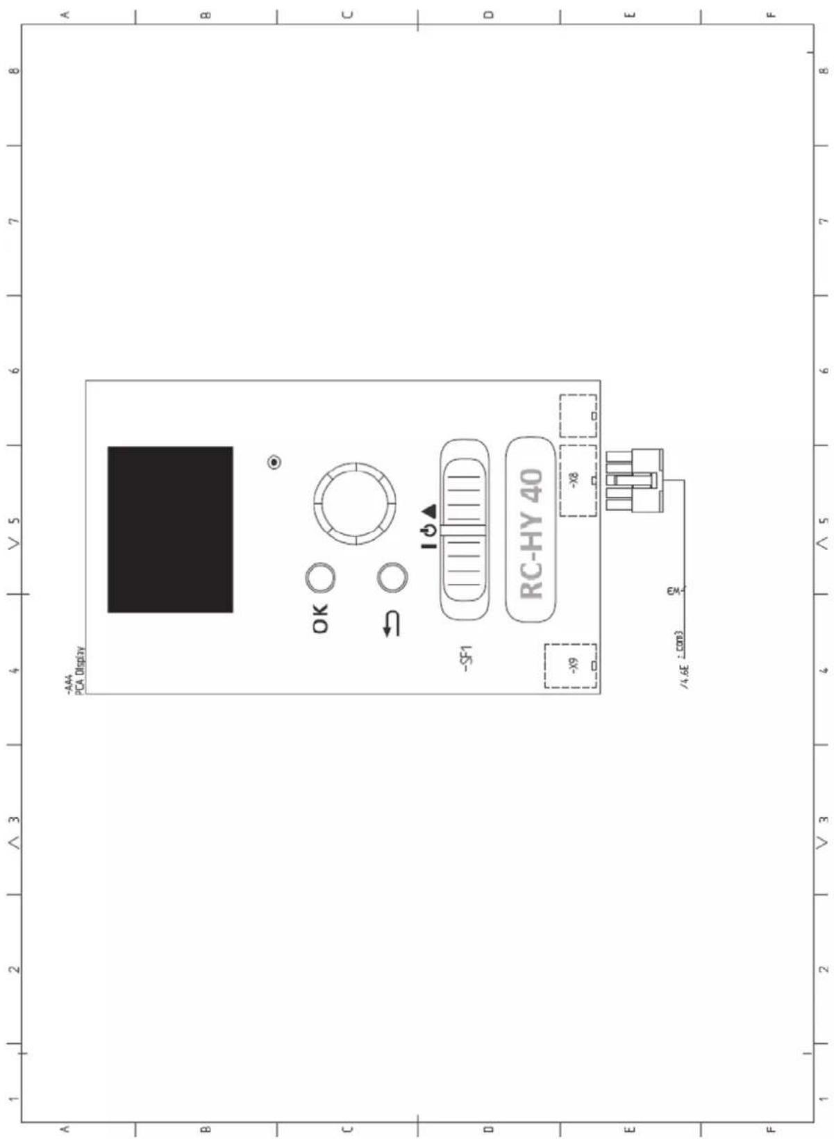

16-5 Konan 2-chome, Minato-ku, Tokyo, 108-8215, Japan
5 The Square, Stockley Park, Uxbridge, Middlesex, UB11 1ET, United Kingdom
Tel: +44-333-207-4072
Fax: +44-333-207-4089
http://www.mhiae.com
- Safety precautions 2
- General information for installer 7
- Pipe installation 14
- Electrical installation 29
- Commissioning and adjusting 56
- Control 62
- Service 75
- Disturbances in comfort 78
- Accessories 83
- Technical data 84
- Safety precautions
- WARNING
- Do not perform any change of protective device itself or its setup condition
- Be sure to switch off the power supply in the event of installation, inspection or servicing.
- Consult the dealer or an expert regarding removal of the unit.
- Stop the compressor before disconnecting refrigerant pipes in case of pump down operation.
- CAUTION
- Carry out the electrical work for ground lead with care.
- Use the circuit breaker with sufficient breaking capacity.
- Earth leakage breaker must be installed.
- Do not use any materials other than a fuse with the correct rating in the location where fuses are to be used.
- Do not install the unit near the location where leakage of combustible gases can occur.
- Do not install the unit where corrosive gas (such as sulfurous acid gas etc.) or combustible gas (such as thinner and petroleum gases) can accumulate or collect, or where volatile combustible substances are handled.
- Secure a space for installation, inspection and maintenance specified in the manual.
- When the outdoor unit is installed on a roof or a high place, provide permanent ladders and handrails along the access route and fences and handrails around the outdoor unit.
- Do not use the indoor unit at the place where water splashes may occur.
- Do not install or use the system close to the equipment that generates electromagnetic fields or high frequency harmonics.
- Do not install the outdoor unit in a location where insects and small animals can inhabit.
- Do not use the base flame for outdoor unit which is corroded or damaged due to long periods of operation.
- Do not install the unit in the locations listed below.
- Do not install the outdoor unit in the locations listed below.
- Do not install the remote controller at the direct sunlight.
- Do not use the unit for special purposes such as storing foods, cooling precision instruments and preservation of animals, plants or art.
- Take care when carrying the unit by hand.
- Dispose of any packing materials correctly.
- Pay attention not to damage the drain pan by weld spatter when welding work is done near the indoor unit.
- Be sure to insulate the refrigerant pipes so as not to condense the ambient air moisture on them.
- Be sure to perform air tightness test by pressurizing with nitrogen gas after completed refrigerant piping work.
- Do not touch any buttons with wet hands.
- Do not shut off the power supply immediately after stopping the operation.
- Do not control the system with main power switch.
- Do not touch any refrigerant pipes when the system is in operation.
- Notabilia for units designed for R410A
- General information for installer
- Over view and design
- Pipe connections
- Valves etc.
- Sensor, thermostats
- Miscellaneous
- Electrical components
- HMK60
- HVAC elements
- Sensors
- Others
- PT300
- Section of the PT300 storage tanks.
- Side view of the PT300 storage tanks.
- Transport and storage
- Supplied components
- Assembly
- HSB60
- IMPORTANT
- RC-HY20/40
- Hanging indoor unit
- NOTE
- Hanging control unit
- Dimensioning expansion vessel
- Initial pressure and max height difference
- Recommended installation order
- Pipe installation
- General
- Installation diagram
- System requirements
- Overflow valve
- Pump capacity diagram
- Pressure drop in indoor unit
- Connection of extra circulation pump
- Dimensions and pipe connections
- Other information
- Water circuit
- Connection to heating system
- Connect XL1 to supply line and X2 to return line from heating system.
- Connection to hot water heater
- Housing disassembly of tank unit
- Connecting hot water tank to indoor unit
- Information
- Connecting hot water tank to water main
- Connection
- Hot water circulation circuit
- Connection of external heat source
- Refrigerant circuit
- Connecting refrigerant pipes
- Piping insulation
- Drain connection
- Dockings
- Installation requirements
- Docking alternatives
- Explanation
- AA25 Controller
- EB1 Additional heat
- EB101 Heat pump system
- EQ1 Cooling system
- Electrical installation
- Principle diagram, electrical installation
- Temperature limiter
- Resetting
- Accessibility, electrical connection for controller
- Cable lock
- HSB60, RC-HY20/40
- Power supply
- Connection between indoor and outdoor unit
- Connection between indoor unit and controller
- Cascade connection setting
- Recommended fuse size for HSB60
- Recommended cable size for HSB60
- Circuit breaker
- Recommended fuse size for HMK60
- Recommended cable size for HMK60
- Connection between controller and indoor unit HSB60
- Connection between controller and circulation pump (GP12)
- Connection between controller and 3-way valve (QN10/QN12)
- • 3-way valve for Heating / Hot water (QN10)
- • 3-way valve for Heating / Cooling (QN12)
- • 3way valve for Heating / Hot water (QN10)
- • 3 way valve for Heating / Cooling (QN12)
- Connection between controller and sensors
- - Ambient air temperature sensor BT1
- • Hot water charging sensor BT6 (tank bottom)
- • Hot water sensor BT7 (tank top)
- • Temperature sensor BT63, outlet at additional heater
- • Temperature sensor BT25, outlet for heating
- • Temperature sensor BT71, return line for heating
- • Temperature sensor BT64, outlet for cooling
- • Temperature sensor BT71, return pipe
- Optional connections
- RC-HY20
- • Room sensor BT50
- • Relay output for emergency mode
- • External circulation pump
- - AUX inputs
- - AUX outputs
- - myUpway™
- RC-HY40
- - Load monitor
- Connecting current sensors
- Commissioning and adjusting Preparations
- Filling and venting
- Hot water tank
- Climate system
- Inspection of installation
- Start-up and inspection
- Before start-up
- Commissioning with heat pump
- Commissioning with additional heater only
- 3-way valve operation check
- AUX function check
- Cooling mode
- Cleaning particle filter
- Secondary adjustment
- Start guide
- TIP
- Commissioning
- Operation in the start guide
- Page
- Name and menu number
- Option / setting
- Help menu
- Heating/cooling curve setting
- heating curve
- cooling curve (accessory required)
- Curve coefficient
- Curve offset
- Flow line temperature – maximum and minimum values
- To select another curve (slope):
- To read off a curve:
- Hot water circulation setting
- hot water recirc.
- operating time
- downtime
- SG Ready
- affect room temperature
- affect hot water
- affect cooling (accessory required)
- Control Display unit
- A Display
- B Status lamp
- C OK button
- D Back button
- E Control knob
- F Switch (SF1)
- G USB port
- Menu system
- Menu 1 - INDOOR CLIMATE
- Menu 2 - HOT WATER
- Menu 3 - INFO
- Menu 4 - MY INSTALLATION
- Menu 5 - SERVICE
- Symbols in the display
- Operation
- Selecting menu
- Selecting options
- Setting a value
- Use the virtual keyboard
- Scroll through the windows
- Scroll through the windows in the start guide
- Help menu
- Sub-menus
- Menu 5.1 - operating settings
- Menu 5.1.1 - hot water settings
- economy
- normal
- luxury
- stop temp. per. increase
- charge method
- Menu 5.1.2 - max flow line temperature
- Menu 5.1.3 - max diff flow line temp.
- max diff compressor
- max diff addition
- Menu 5.1.4 - alarm actions
- Menu 5.1.12 - addition
- max step
- fuse size
- prioritised additional heat
- minimum running time
- min temp.
- mixing valve amplifier
- mixing valve step delay
- transformation ratio
- Menu 5.1.14 - flow set. climate system
- presettings
- own setting
- Menu 5.1.22 - heat pump testing
- Menu 5.1.23 - compressor curve
- Menu 5.2 - system settings
- Menu 5.2.2 - installed heat pump
- search installed slaves
- Menu 5.2.3 - docking (RC-HY 40 only)
- Menu 5.2.4 - accessories
- Menu 5.3 - accessory settings
- Menu 5.3.2 - shunt controlled add. Heat
- start diff additional heat
- Menu 5.3.3 - extra climate system
- use in heating mode
- use in cooling mode
- Menu 5.3.6 - step controlled add. heat
- start addition
- diff. between additional steps
- binary stepping
- Menu 5.3.8 - hot water comfort
- activating imm heater
- activ. imm heat in heat mode
- activating the mixing valve
- outgoing hot water
- flow sensor
- Menu 5.4 - soft in/outputs
- Menu 5.5 - factory setting service
- Menu 5.6 - forced control
- Menu 5.7 - start guide
- Menu 5.8 - quick start
- Menu 5.9 - floor drying function
- length of period 1 - 7
- temp. period 1 – 7
- Menu 5.10 - change log
- Menu 5.11 - heat pump settings
- Menu 5.11.1 - EB101 - EB108
- Menu 5.11.1.1 - heat pump
- Menu 5.11.1.2 - charge pump (GP12)
- - country
- Service
- Service actions
- Maintenance
- General inspection
- Emergency mode
- USB service outlet
- Menu 7.1 - update firmware
- start updating
- choose another file
- Menu 7.2 - logging
- Menu 7.3 - manage settings
- Disturbance in comfort
- Manage alarm
- Alarm
- Troubleshooting
- Basic actions
- Low hot water temperature or a lack of hot water
- Low room temperature
- High room temperature
- Low system pressure
- The compressor does not start
- Additional heating only
- Set the installation to additional heat mode
- Accessories
- Charge pump CPD 11
- External electric additional heat ELK
- Hot water control
- Reversing valve for cooling
- Electrical model
- Anode for tank
- Technical data
- Dimensions and setting-out coordinates
- Electrical circuit diagram
- This manual is only for outdoor units connected to HSB series and HMK series.
- HMK100
- PT300/500
- Section of the PT storage tanks.
- Side view of the PT storage tanks.
- HSB100
- Dimensions and pipe connections HSB100
- HSB100, RC-HY20/40
- Recommended fuse size for HSB100
- Recommended cable size for HSB100
- Recommended fuse size for HMK100
- Recommended cable size for HMK100
- Connection between controller and indoor unit HSB100
- - Step controlled additional heat
- - Relay output for emergency mode
- Pipe installation 13
- Electrical installation 25
- Commissioning and adjusting 42
- Control 48
- Service 61
- Disturbances in comfort 64
- Accessories 69
- Technical data 70
- PT500
- Section of the PT500 storage tanks.
- Side view of the PT500 storage tanks.
- HSB140
- HSB140, RC-HY20/40
- Recommended fuse size for HSB140
- Recommended cable size for HSB140
- Connection between controller and indoor unit HSB140
Brand : MITSUBISHI
Model : HMK60
Category : Heat pump