ExaSAN A16S3-PS - Hard Drive Accusys - Free user manual and instructions
Find the device manual for free ExaSAN A16S3-PS Accusys in PDF.

User questions about ExaSAN A16S3-PS Accusys
0 question about this device. Answer the ones you know or ask your own.
Ask a new question about this device
Download the instructions for your Hard Drive in PDF format for free! Find your manual ExaSAN A16S3-PS - Accusys and take your electronic device back in hand. On this page are published all the documents necessary for the use of your device. ExaSAN A16S3-PS by Accusys.
USER MANUAL ExaSAN A16S3-PS Accusys
Support Host Bus Adapter:
- PCIe 2.0: Z1M-G2
• PCIe 3.0: Z2M-G3, Z2D-G3
Support Host Converter:
• Thunderbolt2.0: C1M-G2
Support Switch System:
- PCIe 2.0: SW16, SWF16
Accusys Storage Ltd.,
Version: V2.0
Revision Sheet
| Version | Date | Revision Description |
| V1.0 | 2014/10/16 | Initial release |
| V1.2 | 2014/11/27 | Add JBOD Setup |
| V2.0 | 2016/7/15 | Content updated |
PREFACE
Notice
The product features and specifications described in this guide are subject to change without notice.
The manufacturer shall not be liable for any damage, or the loss of data resulting from the performance or use of the information contained herein.
About This Guide
Congratulations on your purchase of the ExaSAN (pronounced X-sa-SAN) A16S3-PS. The 16 bay PCIe 3.0 tower model of the ExaSAN family, specifically designed for media streaming workflow. It delivers stability, outstanding performance and scalability. This guide contains instructions for installing and using the A16S3-PS.
Guide to Conventions
Inside the double boxes is important information that users should be aware of:
Caution
This indicates the existence of a potential hazard that could result in personal injury, damage to your equipment or loss of data if the safety instruction is not observed.
Note
This indicates useful tips on getting the most from your RAID system.
Trademarks
Accusys and the names of Accusys products and logos referenced herein are trademarks and/or service marks or registered trademarks and/or service marks of Accusys Storage Ltd.
Xsan, Mac, Mac OS, and Macintosh are either registered trademarks or trademarks of Apple. Other product and company names mentioned herein may be trademarks and/or service marks of their respective owners.
All contents of this manual are copyrighted by Accusys Storage Ltd.
The information contained herein is the exclusive property of Accusys Storage Ltd. and shall not be copied, transferred, photocopied, translated on paper, film, electronic media, or computer-readable form, or otherwise reproduced in any way, without the express written permission of Accusys Storage Ltd..
© Copyright 2016 Accusys Storage Ltd.
All Rights Reserved.
This device complies with Part 15 of the FCC Rules. Operation is subject to the following two conditions: (1) this device may not cause harmful interference, and
(2) this device must accept any interference received, including interference that may cause undesired operation.
ExaSAN A16S3-PS User Guide
Table of content
Page #
Notice....ii
About This Guide....ii
Guide to Conventions ...... ii
Trademarks ...... ii
Table of content......iv
- Introducing ExaSAN PCIe 3.0 Storage System....1-1
1.1 Overview....1-1
1.1.1 What is the ExaSAN Solution....1-1
1.1.2 ExaSAN A16S3-PS features....1-3
1.2 What's in the Box 1-4
1.3 Your A16S3-PS at a Glance....1-5
1.3.1 Front LED Indicators....1-5
1.3.3 Disk Tray and LED Indicators....1-6
1.3.4 Rear Panel....1-7
1.3.5 Plug in/out controller for maintenance....1-7
1.3.6 Z2M-G3....1-8
- Preparing to Install ExaSAN A16S3-PS 2-1
2.1 Precaution for Handling the System....2-1
2.2 Choosing the Location for the System 2-1
2.3 Electrical Power....2-1
2.4 Operating Environment....2-2
2.5 Security....2-2
- Installing the ExaSAN A16S3-PS 3-1
3.1 Rail set installation .... 3-1
3.2 Installing Disk Drive....3-2
3.3 Installing the HBA Card....3-3
3.4 Install driver and GUI....3-5
3.4.1 Installing driver and GUI on MAC and Windows 3-5
3.4.2 Installing driver and GUI on Linux 3-6
3.5 Create Array 3-9
- Using RAIDGuardX GUI.... 4-1
4.1 RAIDGuardX Overview 4-1
4.1.1 Menu Bar....4-1
4.1.2 RAIDGuardX main console....4-2
4.2 Add/Remove Controller 4-3
4.2.1 Add Controller 4-3
4.2.2 Remove Controller....4-3
4.3 Create/Delete an Array 4-4
4.3.1 Create Array....4-4
4.3.2 Delete an Array 4-6
4.4 Email Notification....4-7
4.5 Preference....4-8
4.5.1 Disk Lag Proof....4-8
4.5.2 NCQ....4-9
4.5.3 SMART Mode 4-9
4.5.4 Beeper....4-10
4.5.5 Equalization Mode 4-10
4.5.6 Cache 4-10
4.5.7 MISC 4-11
4.6 Option....4-13
4.6.1 Slicing 4-13
4.6.2 LUN Map....4-14
4.6.3 Expansion 4-15
4.6.4 Migrations....4-16
4.6.5 Snapshot....4-19
4.6.6 Health Center 4-22
4.6.7 Unlock Drives 4-23
4.7 Updating the ExaSAN RAID system Firmware 4-25
4.8 Download controller log....4-26
4.9 Disk RW Test....4-26
RAID Overview....5-1
5.1 How RAID Works 5-1
5.2 RAID Levels....5-1
5.2.1 RAID 0: Striping....5-1
5.2.2 RAID 1: Mirroring....5-2
5.2.3 RAID 5: Striping disks with distributed parity ....5-2
5.2.4 RAID 6: Independent data disks with two Independent parity schemes....5-2
5.2.5 RAID 0+1: Striped set with Mirroring....5-3
5.2.6 Enhance JBOD: Single disk....5-3
Appendices....6-1
Appendix A: FAQs 6-1
Appendix B: Customer Service and Support....6-4
1. Introducing ExaSAN PCIe 3.0 Storage System
1. Introducing ExaSAN PCIe 3.0 Storage System
1.1 Overview
1.1.1 What is the ExaSAN Solution
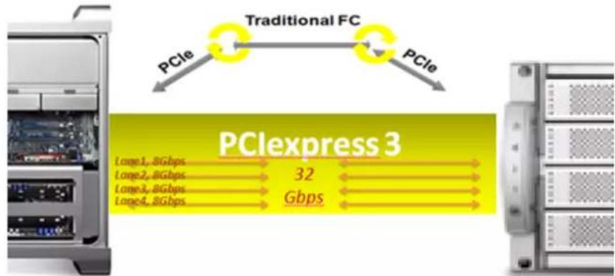
Developed by Accusys Storage Ltd., a worldwide leader in RAID (Redundant Array of Independent Disks) storage systems, ExaSAN (pronounced "X-sa-SAN") is a family of storage and switch products that take advantage of well known PCIe (PCI Express) technology speeds, standards, and roadmap.
The current ExaSAN products employ PCIe3.0 protocol that provides 8 Gb/s per lane transfers. With 4 lane QSFP (Quad SFP) connector and cable, ExaSAN can transfer up to 32 Gb/s by using single connection.
Post production work including non-linear editing (NLE) requires high bandwidth storage to quickly move the volume of data being processed and ExaSAN storage solution meets those demands. The high bandwidth provided by ExaSAN technology allows the client to complete editing tasks in a much shorter time to save time and money.
flowchart
graph LR
    A["PCExpress 3"] -->|PCIe| B["Traditional FC"]
    B -->|PCIe| A
    A --> C["Large1, 8Gbps"]
    A --> D["Large2, 8Gbps"]
    A --> E["Large3, 8Gbps"]
    A --> F["Large4, 8Gbps"]
    A --> G["32 Gbps"]
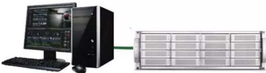
ExaSAN solution, including its complete line of rack mount RAID systems, tower RAID systems, PCIe switch systems and accessories, for different application purpose, user can build as DAS (directly attached storage) via PCIe3.0 interface to provide extremely performance, in addition, Accusys provide SAN (storage attached network) turnkey solution to build a fast and shareable storage.
natural_image
Computer setup with monitor, tower, keyboard, and rack unit (no visible text or symbols)Standard DAS Environment
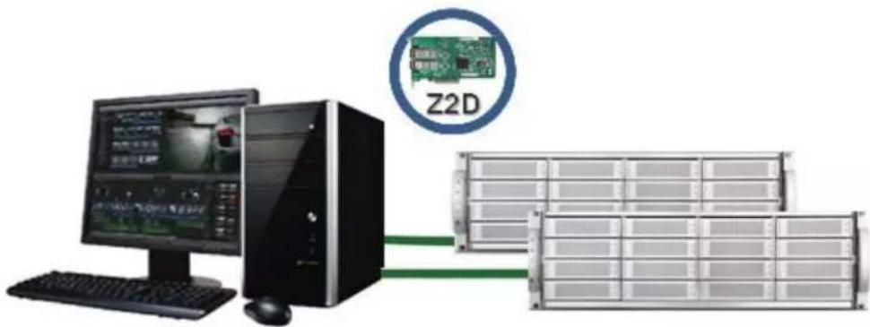
DAS with Z2D-G3, refer to below link to know more detail about Z2D-G3 http://www.accusys.com.tw/Accessories/HBA-Cable.html
natural_image
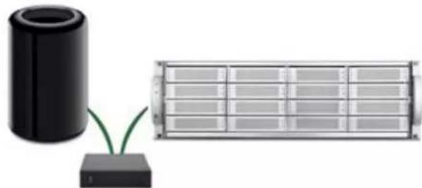
Two electronic components: a black cylindrical device connected to a small green connector and a rectangular grid-like device (no text or symbols visible)Thunderbolt 2 DAS with C1M-G2, refer to below link to know more detail about C1M-G2 http://www.accusys.com.tw/Accessories/C1M.html
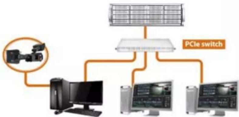
flowchart
graph TD
    A["PCIE switch"] --> B["Solar Panel"]
    A --> C["Computer"]
    A --> D["Monitor 1"]
    A --> E["Monitor 2"]
    A --> F["Monitor 3"]
SAN environment, refer to link for more detail of how to build a SAN environment. http://www.accusys.com.tw/ExaSAN/SW16.html#
ExaSAN solution offers a range of performance levels and storage capacities that scale to meet the needs of small-to-medium-sized organizations. Equally important and useful is its integrated design, centralized administration and monitoring, and a suite of built-in management tools; which eliminate the need for a staff of experts to install and maintain a SAN for the workgroups
1.1.2 ExaSAN A16S3-PS features
1. Hardware Specifications
• One PCIe3.0 8Gb/s x4 lanes host port, transfers up to 32 Gb/s
- Hardware XOR/Multi-Parity engine
• 2GB DDRIII memory, ECC-protected
• Support 16 x 3.5"/2.5" SAS/SATA drive and SSD
• Support expand to 3 JBOD Enclosures
- Redundant 400W power module
2. Software Specifications
- Multiple RAID levels: 0,1,5,6, 0+1 and enhance JBOD
- Up to 5 disk array groups
- Up to 16 disk array slices
- Up to 64 LUNs
- Selective initialization method (on-the-fly and performance evaluation)
• Online RAID set expansion and level migration - Support write-back and write-through caching of controller and drive
• Automatic rebuilding - Disk health monitoring by S.M.A.R.T.
- Disk RW Test to measure the real IO throughput on each disk
- Array roaming and disk traveling
- Dual firmware images for firmware recovery
- Disk Lag Proof technology to guarantee disk timely response
- Equalization mode to smooth the performance of sequential data transfers
3. Management
- Java-based GUI, RAIDGuardX, centralized multiple RAID system management
• LED indicator to monitor status of RAID enclosure
• Event notification by email (SMTP) - Support SNMP traps
4. Enclosure
- Dimensions: L: 567mm, W:441mm, H: 131mm
• Weight: 19.4 Kg, 42.7 lbs (w/o drives)
5. Support OS
• Windows 7, 8, 10, 2008 and 2012 (32/64bit)
• Linux: Red Hat, SUSE, Fedora, CentOS etc.
• MAC: OS X 10.5, 10.6, 10.7, 10.8, 10.9, 10.10 and 10.11.
6. Operating Conditions
• Humidity: 5% - 85%
- Operating Temperature: 0C – 40C
7. Certification
• Humidity: 5% - 85%
- Operating Temperature: 0C – 40C
• Certification: RoHS, CE, FCC, BSMI
8. Support Cable
• Copper 2M (standard), Optical 10M, 30M, 50M and 100M.
1.2 What's in the Box
Your ExaSAN A16S3-PS is shipped in special packaging to provide protection during transportation. Carefully check your carton contents against the included packing list, or the inside flap of the box, and your original purchase order. You should have the items as described in the sections below.
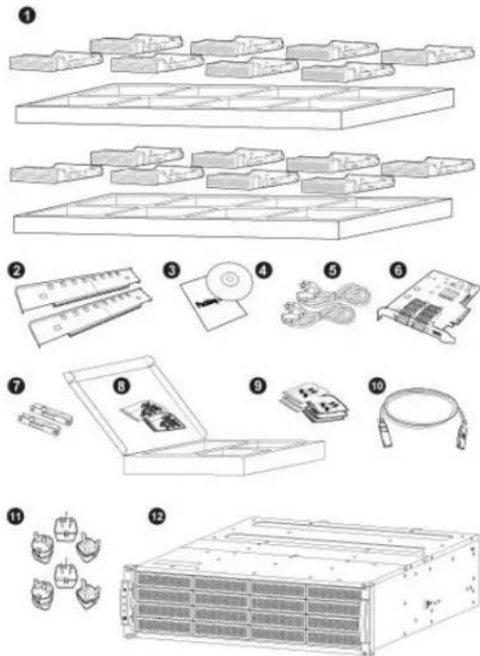
- Disk tray (x16)
- Rail set (x2)
- Packing List (x1)
- Installation USB (x1)
- AC power cord cable (x2)
- Z2M HBA card (x1)
- Rail extender (x2)
- Screw pack for disk tray (x2)
- Screw pack for disk rack (x6)
- 2M QSFP copper cable (x1)
- Plug adapter (x6)
- ExaSAN A16S3-PS storage (x1)
1.3 Your A16S3-PS at a Glance
1.3.1 Front LED Indicators
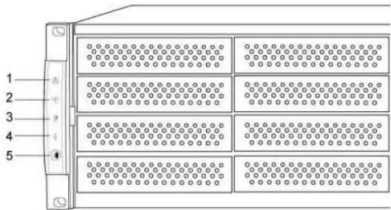
| No. | Name | Description |
| 1 | Controller Status | Blue RAID System alive or in accessRed RAID System failed |
| 2 | FAN | Blue FANs work normalRed One of FAN failed |
| 3 | Temperature | Blue Temperature normalRed Temperature over the value |
| 4 | Power Module | Blue Power modules work normalRed One of Power module failed |
| 5 | Mute Button | Pushing the button for 2 seconds will mute the system beeper. If another abnormal event occurs, the beeper will alarm again. |
| 4 | Disk status | Disk 1 (top) ~ 16 statusGreen disk onlineRed disk fail or offlineGreen/Red Switching disk rebuild, migrate or expand |
| 5 | Disk activity | Disk 1 (top) ~ 16 activityBlue disk in access |
1.3.2 Disk Mapping
1.3.3 Disk Tray and LED Indicators
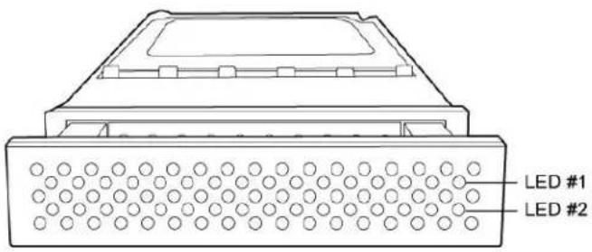
| Disk Status | LED #1 (Access LED) | LED #2 (Status LED) |
| Disk Online/Locked | Steady Green | |
| No Disk/Disk Fail | Steady Red | |
| Disk Access/Initialization | Flashing Blue | Steady Green |
| Disk Rebuild | Flashing Blue | Switching in Red and Green |
| Disk Expansion | Flashing Blue | Extend Drives: Steady RedOriginal Drives: Steady Green |
| Disk Migration | Flashing Blue | Migrate Drives: Steady RedOriginal Drives: Steady Green |
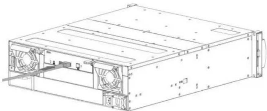
1.3.4 Rear Panel
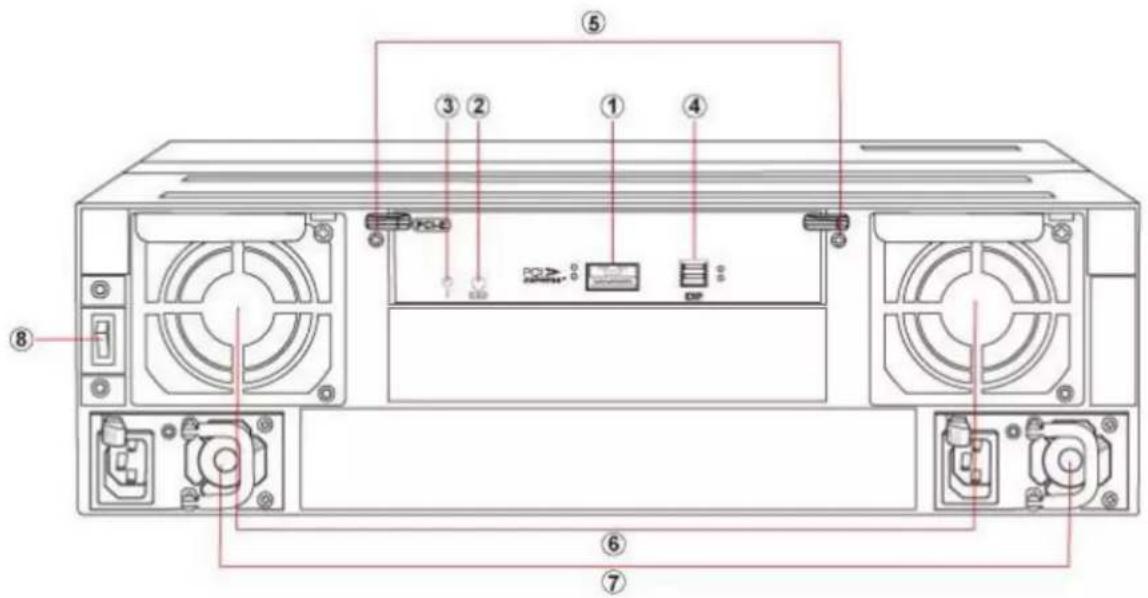
| No. | Name | Description | |
| 1 | QSFP host port | PCIe3.0 host port | |
| LED(left) | Green PCIe3.0 link statusFlash Green PCIe2.0 link status | ||
| LED(right) | Blue Data access status | ||
| 2 | Debug port | For engineer debugging only. | |
| 3 | Heart beat LED | Flashing green indicates work normal. | |
| 4 | JBOD Expansion port | Expanding to another JBOD enclosure. | |
| LED(left) | Green Link status | ||
| LED(right) | Blue Data access status | ||
| 5 | Controller Handler | 1.3.5 Plug in/out controller for maintenance. | |
| 6 | Redundant Fan | Hot swappable cooling Fan modules | |
| 7 | Redundant Power | Hot swappable Power Supply modules | |
| 8 | Power switch | Switch on/off the RAID system | |
1.3.6 Z2M-G3
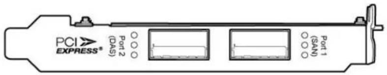
| No. | Name | Description | |
| 1 | QSFP Port 1 | For connection with switch. | |
| LED1 | Amber SAN mode enable | ||
| LED2 | Green PCIe3.0 Link statusFlash Green PCIe2.0 link status | ||
| LED3 | Blue Data access status | ||
| 2 | QSFP Port 2 | For connection with ExaSAN storage directly. | |
| LED1 | Reserve | ||
| LED2 | Green PCIe3.0 Link statusFlash Green PCIe2.0 link status | ||
| LED3 | Blue Data access status | ||
Refer to the link http://www.accusys.com.tw/Document/HBA_Cable/Z2M_G3_QSG_20141216.pdf, for more detail about Z2M-G3.
2. Preparing to Install ExaSAN A16S3-PS
2. Preparing to Install ExaSAN A16S3-PS
To ensure safe and smooth operation of your ExaSAN A16S3-PS, it is essential that you choose an appropriate location for the system, provide an appropriate operating environment, and adequate power for all components of the system. As you plan for installation, follow the guidelines below to ensure that the system and its environment are safely and appropriately positioned for efficient operation and service.
2.1 Precaution for Handling the System
Take the following precautions to avoid damage to the system or potential injury to you.
- Prepare a flat, sturdy surface before removing the system from its packaging. The table or cart that will hold the system should be as close as possible to the system carton.
- Ensure that all power switches have been turned off and all power cords disconnected to prevent personal injury and damage to the hardware.
- Static electricity can damage electronic components of your system. Follow the guidelines below to avoid such damage:
a. Work in a static-free environment
b. Wear a grounded anti-static wrist strap
c. Store uninstalled components in anti-static bags
d. Handle circuit boards by their edges and avoid touching chips and connectors
2.2 Choosing the Location for the System
The ExaSAN A16S3-PS is designed as a tower solution. Depending on where your desk or rackmount cabinet or other install location is, you should keep the following points in mind when determining where to place your system.
- Measure the available space on your desk for the space required for the A16S3-PS. (Refer to chapter 1.1.2 for the dimension.)
- Measure the distance between any two components that need to be connected via cable(s). This measurement will help you determine the length of the required cable(s). Or if you've already purchased the cables, determine the proximity of the components in question.
- Leave sufficient room, at least two inches, around the unit to allow air ventilation.
- Do not block or cover any of the ventilation holes in the front and back panels of the unit. Consistent airflow is essential to keeping the system operating efficiently.
- Allow additional room at the front and back of the unit for service.
- The ExaSAN A16S3-PS uses several cables and cords. It's a good idea to determine how they will be arranged at the rear of the system, and where the cables will be routed to connect to the host systems and RAID disk systems.
2.3 Electrical Power
At your chosen location for the ExaSAN A16S3-PS, make sure that the electrical circuitry and power outlets are sufficient for the combined power needs of all hardware components. To plan for safe and adequate power to the system, follow these guidelines:
- Check the documentation for all hardware components at the chosen location to determine their power requirements. Then make sure that the available power supply for that location is sufficient for the planned components.
-
When possible use surge protectors or power conditions as part of the installation.
-
When planning for electrical power, make sure you have more power than the total power requirements specified for all components. Also make certain that the power load is distributed evenly among circuits to that location. Consult an electrician or other expert if you need assistance with planning for the power needs for your components.
- Make sure that the power outlets for all hardware components are grounded according to local and national standards. Consult an electrician if you need assistance with grounding.
2.4 Operating Environment
The operating environment for the ExaSAN A16S3-PS must meet certain requirements:
- Verify that the temperature range of the chosen location is within the limits established for the system and all other components.
- Make certain that the chosen location has adequate ventilation to maintain the necessary temperature range.
- If there are multiple hardware components installed at the chosen location, consider additional cooling measures to assure efficient operation of the system and other components.
- Environment parameters:
a. Operating temperature: 0°C to 40°C (32°F to 104°F)
b. Operating humidity: 5-85%, non-condensing
c. Storage humidity:5%-95%, non-condensing
2.5 Security
To ensure the security of the ExaSAN A16S3-PS, make certain that the chosen location meets your security requirements.
- Installing the ExaSAN A16S3-PS
3. Installing the ExaSAN A16S3-PS
Follow the steps in this chapter to install your ExaSAN A16S3-PS system
3.1 Rail set installation
A16S3-PS is designed as standard 19inch 3U chassis, support all standard rack. Follow the steps to properly install you RAID system into rack.
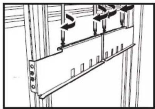
- Loosen rail screws of rail set, and adjust the length to fit your rack
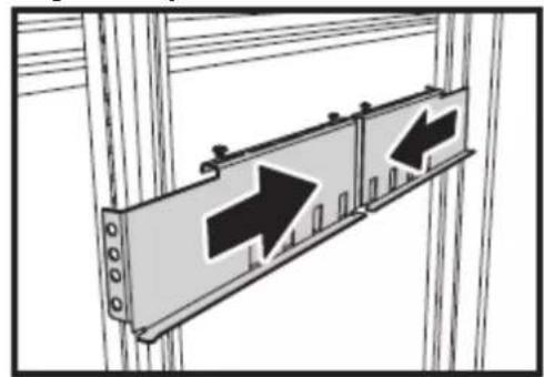
natural_image
Diagram of two directional traffic signs mounted on a wall, with arrows indicating direction (no text or symbols present)- Tighten 2 rack screws in both front and rear side.
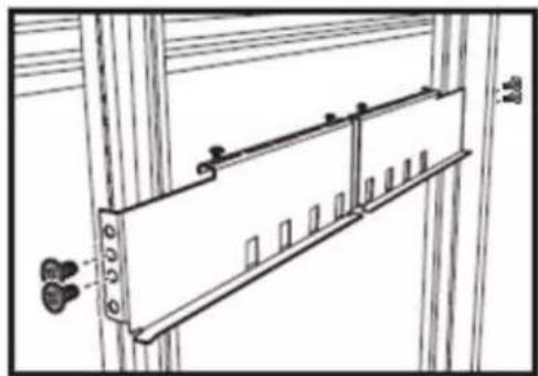
natural_image
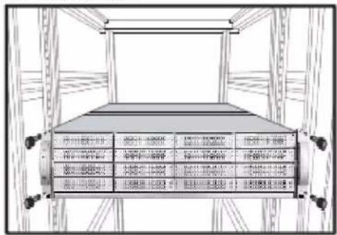
Technical line drawing of a cabinet or enclosure with doors, doors, and windows (no text or symbols)- Tighten 4 rail screws.
natural_image
Technical line drawing of a mechanical assembly with mounting brackets and directional arrows (no text or symbols)- Install RAID system into the rack and securing with 4 rack bolts.
3.2 Installing Disk Drive
Follow the steps below to install your Drives.
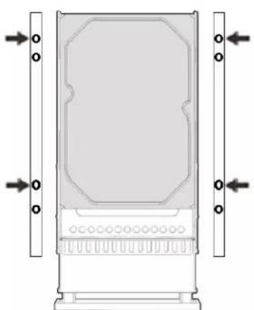
- Place the Drive with connector align with the edge of the disk tray and secure drive with screws as below figure.
natural_image
Technical diagram of a rectangular device with mounting base and side connectors (no text or symbols)Four screws for 3.5"
natural_image
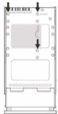
Diagram of a device casing with internal components and directional arrows indicating movement (no text or symbols)Three screws for 2.5"
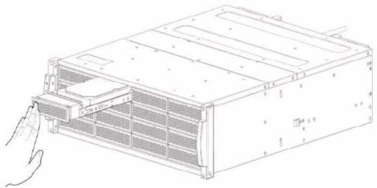
- Push the tray inward until the tray firmly connects and you hear the tray click into place.
natural_image
Line drawing of a computer rack unit with a hand inserting a component (no text or symbols visible)- Repeat for all drives to be installed into the A16S3-PS.
Note
Recommend using drives with same size, speed, model and firmware version.
3.3 Installing the HBA Card
Before the ExaSAN A16S3-PS is ready to be connected and powered on, you must install the HBA card in the workgroup client system. The HBA card is compatible with PCIe x8, x16 slots and both PCIe 2.0, 3.0 standards. Note, recommend to use PCIe x16 slots.
Note Caution
PCIe slots on some motherboards are for graphics cards only. Check with the motherboard vendor for compatibility.
Follow these steps to install the card in host system:
-
Make sure that the client system is turned off.
-
Open the client system's outer casing cover, check with your vendor documentation for instructions if necessary.
-
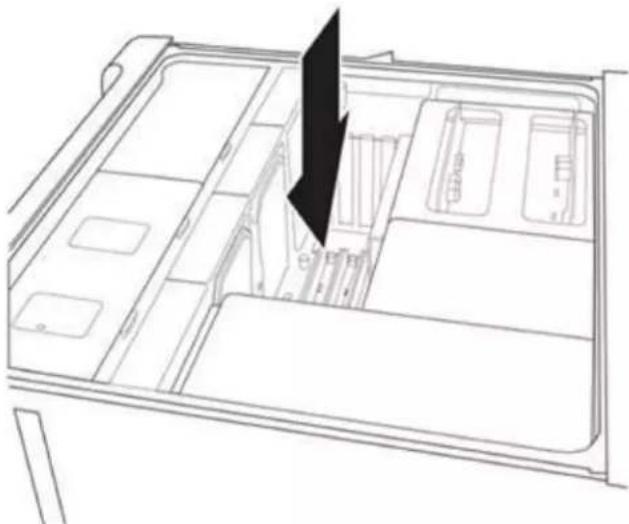
Locate the available PCIe slot.
natural_image
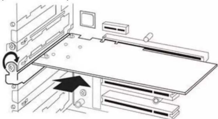
Line drawing of a refrigerator interior with compartments and storage bins (no text or symbols)- Position the connector of the card over the slot, insert the connector into the slot, press gently but firmly until it is securely seated.
natural_image
Technical line drawing of a mechanical assembly with no visible text or symbols-
Put back the outer casing cover and you are done.
-
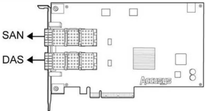
Connect QSFP cable to Z2M HBA, there are DAS and SAN ports.
• DAS port: Enable for DAS (Direct-Attached Storage) mode.
- SAN port: Enable for SAN (Storage-Attached Network) mode, support to ExaSAN switch. (Refer to link for more detail of how to build a SAN environment. http://www.accusys.com.tw/ExaSAN/SW16.html#)
- Connect the other end of QSFP connector to ExaSAN A16S3-PS.
natural_image
Technical line drawing of a computer drive chassis with fan blades and ventilation slots (no text or labels)- Power on A16S3-PS, RAID will ready in few seconds with sounding a short bi, and then power on host system to install driver and GUI.
Caution
Once powered on, Do NOT remove the QSFP PCIe cable when in use to avoid data loss and corruption.
3.4 Install driver and GUI
Installation files can be found in installation USB, or you can download the latest version from our website (http://www.accusys.com.tw/support/download.html). If you need further technical support, please contact your reseller or Accusys support team. (see Appendix B “Customer Service and Technical Support” for more information)
Note
- For Mac/Windows platform: Double click installer package to install driver and GUI both.
- For Linux platform: Linux driver and GUI must be installed separately and manually.
3.4.1 Installing driver and GUI on MAC and Windows
Installer files can be found in installation USB, or you can download the latest version from our website (http://www.accusys.com.tw/support/download.html). If you need further technical support, please contact your reseller or Accusys support team. (see Appendix B “Customer Service and Technical Support” for more information)
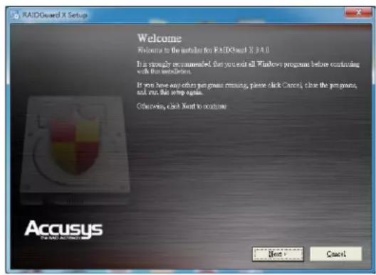
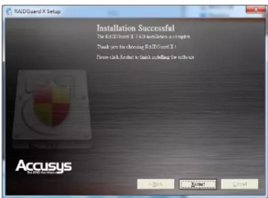
- For Mac, double click the file "/MAC Installer/Vx.x/Accusys_IP_MAC x.x.x.mpkg".
- For Windows, double click the file "/Windows installer/Vx.x/Accusys_Win_x.x.exe". Follow the onscreen instructions to install and click Restart to complete installation.
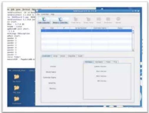
3.4.2 Installing driver and GUI on Linux
Linux driver and GUI must be installed manually; following procedures will guide how to do
- Driver installation
• RAIDGuardX installation
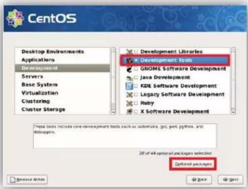
- You must have your Linux system with developmental environment, in order to make driver for respective Linux kernel. For example, when installing CentOS, you should check "Development Tools > Optional Packages".
- Open a terminal window, change to Linux driver source directory and type command 'make' to build driver file 'ACS6x.ko'
# sudo make
![[root@localhost Linux_Dry_3.1.8]# ls ACS6x.ko acs_ame.h ame.h AME_Queue.c AME_Raid.o MPI0.c ACS6x.mod.c acs_ame.o AME_import.h AME_Queue.h built-in.o MPI0.h ACS6x.mod.o ACS_MSG.c AME_module.c AME_Queue.o Makefile MPI0.o ACS6x.o ACS_MSG.h AME_module.h AME_Raid.c Module.markers OS_Define.h acs_ame.c ACS_MSG.o AME_module.o AME_Raid.h Module.symvers](/content/2026/05/1061745/images/514400dd3c8747206a37dab0f4162797831a890d4238ac18f9dd2aee60efb9c7.jpg)
# sudo insmod ACS6x.ko
# sudo lsmod //to see if ACS6x driver is running
![[root@localhost Linux_Drv_3.1.8]# insmod ACS6x.ko [root@localhost Linux_Drv_3.1.8]# lsmod Module Size Used by ACS6x 138120 0 autofs4 57033 2 hidp 83521 2 rfcomm 104809 0 l2cap 89281 10 hidp,rfcomm bluetooth 118597 5 hidp,rfcomm,l2cap blockvt 260300 4 nfs 314412 1 blockvt lockd 99185 1 nfs exportfs 38849 2 blockvt,nfs fscache 52385 1 nfs nfs_acl 36673 1 nfs sunrpc 197897 5 blockvt,nfs,lockd,nfs_acl cpufreq_ondemand 42449 1 acpi_cbufreq 47937 3](/content/2026/05/1061745/images/918f1e7073f75aac622aa4df5e07e83de1055fb4865e3a814ddedab729eecb05.jpg)
- Start ACS6x.ko driver automatically after reboot
A. Copy driver file ACS6x.ko to driver folder.
# sudo cp ACS6x.ko /lib/modules/{linux kernel}/kernel/drivers/scsi
(Note: 'uname -a' can find {linux kernel})
B. Upgrade all default modules
//For RHEL, CentOS, Ubuntu, etc
sudo depmod -a
// For SUSE, SLES
Set the line "allow_unsupported_modules" from 0 to 1 by editing /etc/modprobe.d/unsupported-modules
C. Reboot to make it available
3.4.2.2 RAIDGuardX Installation
Before running RAIDGuardX, make sure the driver is running.
- You will need two source files; GS (RAIDGuardX Server) and GC (RAIDGuardX Client), you can download from Accusys website: http://www.accusys.com.tw/Support/Download/
GS location:/{ExaSAN model}/GUI/Server/Linux.zip
GC location:/{ExaSAN model}/GUI/Client/x.x.x.zip
Note
- If ExaSAN storage is connected on PCIe switch, GS may not necessary; GC can manage RAID system remotely through Ethernet.
- Perform GS, open a terminal console, and enter the following commands:
# sudo cd /Accusys/GS/Linux/X.X.X
# sudo chmod -R 777 SourceCode
# sudo cd /Accusys/GS/Linux/X.X.X/SourceCode/
# sudo ./make.sh
# sudo cd /Accusys/GS/Linux/X.X.X/AP_Accusys/
# sudo ./DTRGuiSrv_64 //RAID controller serial number would appear once GS ran success
![[root@localhost Desktop]# cd Accusy/GS/Linux/3.1.7 [root@localhost 3.1.7]# ls AP_Accusys readme.txt SourceCode [root@localhost 3.1.7]# chmod -R 777 SourceCode [root@localhost 3.1.7]# cd SourceCode/ [root@localhost SourceCode]# ls binreloc.c cNetWork.c nInBand.h NSIO_1304.h binreloc.n cPollingEvent.c hInclude.h NSIO_x86.h cDTRioCtl.c cSemaphore.c MMail.h NSrvConfig.h cFindRaidCard.c cShareMem.c hNetWork.h Makefile (.linux) cINBand.c clrvConfig.c hPollingEvent.h make.sh Class DTRGuiSrv hSemaphore.h myUserClientStuff.c cMail.c hDeclar.h nShareMem.h nyUserClientStuff.h cMain.c dTRioCtl.n nSI0.h [root@localhost SourceCode]# ./make.sh [root@localhost SourceCode]# cd ... [root@localhost 3.1.7]# cd AP_Accusys/ [root@localhost AP_Accusys]# ls activation.jar EchoBack.class SendMail.class DTRGuiSrv jMsgFrame.class sock2srv.class DTRGuiSry_64 mail.jar sock2thread.class EchoAliveThread.class MsgThread.class srvGui_reg_frame.class EchoBacks1.class MulticastReceiver.class UDPBombermanServer.class EchoBacks2.class SendMail1.class UDPServer.class [root@localhost AP_Accusys]# ./DTRGuiSrv_64 GS.73_3.1.7 (Jun 13 2014 - 18:36:06); Start initialize share Mem for GUI Config ... I am duty. Leave !!! [root@localhost AP_Accusys]# Start initialize share Mem for all Ctlrs ... Find DTR RAID Card... pSignature match ACCUSYS 20651-Mathsetish - Del! dCtrlSM: aBOS303333333333333 Del: Use DON: Out MMode\Name: A8853-PS](/content/2026/05/1061745/images/e67876fdaba40fe28d2bce2b4a43759033e105b0fd4df19866e2ad3b351b857b.jpg)
- Open another terminal, make sure the Java version is higher than 1.6, enter the following commands:
# java -version
[root@localhost ~]# java -version
java version "1.6.0_14"
Java(TM) SE Runtime Environment (build 1.6.0_14-b08)
Java HotSpot(TM) Client VM (build 14.0-b16, mixed mode, sharing)
[root@localhost ~]#
If your Java version is earlier than 1.6, please upgrade from www.java.com
- Perform GC, enter the following commands
<h1 id="sudo-cd-accusysgc3xx3xx">sudo cd /Accusys/GC/3.x.x./3.x.x/</h1>
<h1 id="sudo-java-jar-raidguardxjar-raidguardx-client-console-would-appear">sudo java -jar RAIDGuardX.jar //RAIDGuardX Client console would appear</h1>
[root@localhost ~j# cd Desktop/Accusy/GC/3.1.8/3.1.8/
[root@localhost 3.1.8]# ls
help RAIDGuard X.app RAIDGuardX.jar
[root@localhost 3.1.8]# java -jar RAIDGuardX.jar
- Now you can add controller to manage ExaSAN RAID system.
3.5 Create Array
Array can be created by few clicks on RAIDGuardX (refer to Section: Creating an Array for more detail);
- On RAIDGuardX, select RAID level, Sector size, drive member and initialization type, then check Assign LUN automatically and press Create Array bottom to complete.
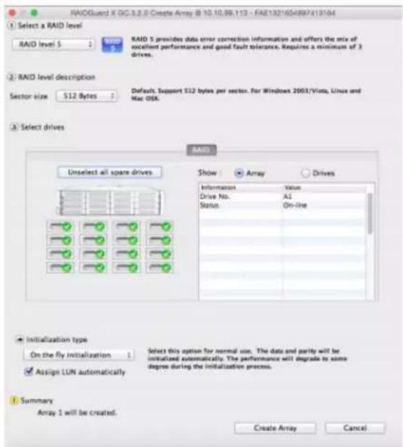
- New disk volume should appear on host OS immediately, format it as type as you want and enjoy the high speed access on ExaSAN storage.
4. Using RAIDGuardX
4. Using RAIDGuardX GUI
4.1 RAIDGuardX Overview
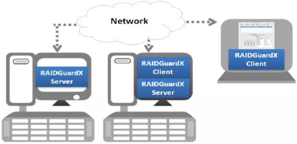
RAIDGuardX support local and remote monitoring of multiple controllers that are connected to the same network, which consist of 2 components: RAIDGuardX-Server and RAIDGuardX-Client.
flowchart
graph TD
    A["RAIDGuardX Server"] --> B["Network"]
    C["RAIDGuardX Client"] --> B
    D["RAIDGuardX Server"] --> B
    B --> E["RAIDGuardX Client"]
RAIDGuardX-Client: A java-based console for managing and monitoring RAID system.
RAIDGuardX-Server: RAIDGuardX-Server is an agent service in charge of communication between RAIDGuardX-Client and RAID controller; it MUST be installed to the host directly connected to RAID system.
4.1.1 Menu Bar

RAIDGuard X File Controller Help
The menu bar across the top contains the following functions:
| Function | Description | |
| File | Exit | Close the program |
| Load Controller List | Refresh the controller list | |
| Language | English and Japanese are supported | |
| Controller | Manual Add Controller | Add remote controller by IP address of RAIDGuardX-Server |
| Update | Update firmware (System Code, Boot Code, etc.) | |
| Dump controller log | Download controller log for troubleshooting | |
| Disk RW Test | Test Read/Write speed on each disk | |
| Help | Search | Search keyword in RAIDGuard X |
| Help Center | Displays the help for RAIDGuard X | |
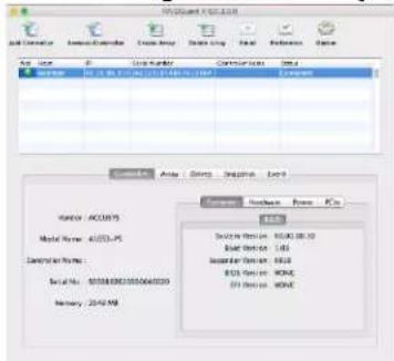
4.1.2 RAIDGuardX main console
![Monitoring buttons (to connect to systems) Add Controller Remove Controller Create Array Delete Array Email Preference Option MANU-02 8.6C 3.2 Management buttons Message area Host IP Serial Number Controller Name Status Connected Location: [19.19.79 122 (G2A)164(00)111(111)] Connected Monitoring tabs System information Vendor : ACCUSYS Model Name : A0B53-PS Controller Name : Serial No. : 5000662321500380 Memory : 2048 MB Command: Hardware Power PCIe SADL System Version : 00.00.32.00 Root Version : 1.07 Expander Version : BIOS Version : NONE BPI Version : NONE Advanced information for each Monitoring tab](/content/2026/05/1061745/images/85b67944ac60c4f648a6708f5decc6a308e68fb0c162acf0c09a6e0a85366fe9.jpg)
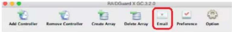
| Function | Description | |
| Monitoring Buttons | Add controller into RAIDGuardX (for DAS only) | |
| Remove controller from RAIDGuardX | ||
| Management Buttons | Create array in the RAID system | |
| Delete array in the RAID system | ||
| Email to set email notification | ||
| Preference | Drive Lag Proof Enable/ Disable | |
| NCQ mode Enable/ Disable | ||
| SMART Mode Enable/ Disable | ||
| Beeper Enable/ Disable | ||
| Equalization Enable/ Disable | ||
| Cache of controller and drives can be enable/disable | ||
| MISC for controller Time setup | ||
| Option | Slicing an existing array for multiple slices | |
| LUN Map setup for multiple slices | ||
| Expansion with new drive into an array | ||
| Migration between different RAID level | ||
| Snapshot for backup data in a particular time | ||
| Health Center for check array status | ||
| Unlock Drives from locked mode | ||
4.2 Add/Remove Controller
RAIDGuardX can manage the RAID controller locally or remotely via intranet access.
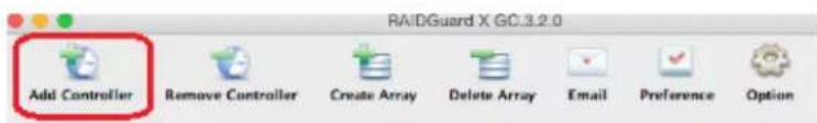
4.2.1 Add Controller
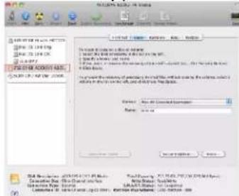
- Open RAIDGuardX-Client, you may add controller by locally or remotely;
Locally: Click Add Controller to display a list of available controllers
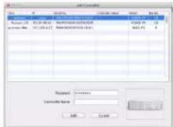
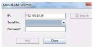
Remote: Click Controller tab > Manual Add Controller, type the remote host IP address (Where the RAIDGuard-Server installed is), click search to display all available controllers.
- Click on a controller and enter password (default is 00000000, 8 zeros), then you can type a controller name to remark, click Add to open main console
Note
Password can be changed in section Preference > MISC.
- In main console, you can monitor and manage this RAID system.
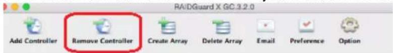
4.2.2 Remove Controller
Click Remove Controller icon can remove this RAID system out of RAIDGuardX.
4.3 Create/Delete an Array
This chapter will guide you how to use RAIDGuardX to create/delete disk array.
4.3.1 Create Array
- Click icon Create Array, then create array page will pop up as below,
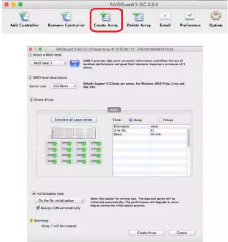
- Select the RAID level from the drop down menu. Available levels are: 0, 1, 5, 6, 0+1, enhanced JBOD. Find more details in Chapter 5 RAID Overview
- Select the sector size. Available sector sizes are 512 bytes (default) and 4096 bytes. The sector size 4096 bytes is only used on WinXP for recognized over 2TB volume.
- Click on the drive icon or Select all spare drivers to select all available drives.
Note
Unselected drive will be set to Hot (Global) spare drive. If an array member drive fails, spare drive will start to rebuild automatically.
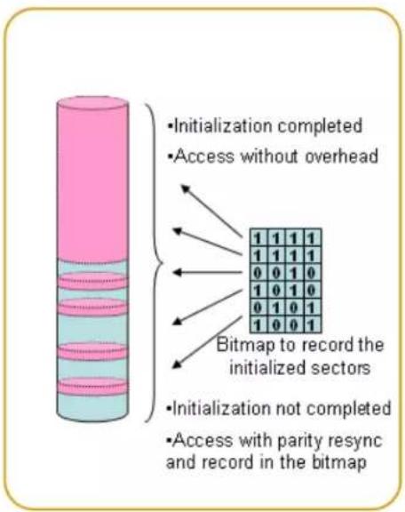
- Click the initialization type: On-the-fly initialization or Performance evaluation.
On-the-fly initialization (Default) – While RAID systems record the initialized sectors in the bitmap, you can still use the RAID system during the initialization.
Performance evaluation – Select to evaluate the performance of the target array. It will take no time for array initialization; there is no data protection, only for testing purpose.
Caution
Array created by Performance evaluation could not do array rebuild, DO NOT use this type for production environment.
- Check Assign LUN automatically. You can change LUN map in Options anytime.
- Select which host port could be visible this array.
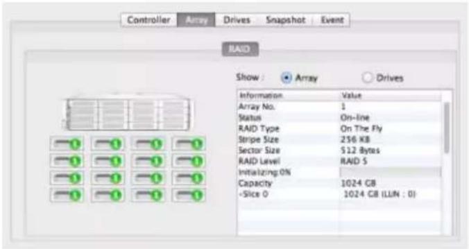
- Click Create Array to start array initialization, you can see the status of array initialization progress.
Note
Up to 5 array groups.
4.3.2 Delete an Array
- Click icon Create Array on RAIDGuardX, then it will pop up a dialog as below picture
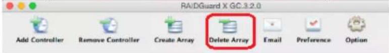
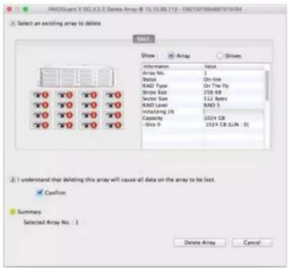
- Click on the drive icon of the array to be deleted.
- Check the Confirm box. Click Delete Array to complete the process.
Note
Array cannot be deleted during any actions, e.g. initialing, rebuilding.
Caution
When delete an array, all data on the hard disk drives will be lost.
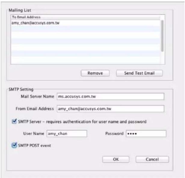
4.4 Email Notification
It may be necessary for network administrators to receive e-mails in the event of errors, alerts, and changes to the RAID array. These alerts can be e-mailed to a maximum of 20 e-mail addresses.
1. Mailing List
Enter the e-mail address of people to receive controller error reports.
Click Remove to delete e-mail addresses from the list.
Click Send Test Email to check that the e-mail is working.
2. SMTP Setting
Mail Server Name – Enter the address of the mail server.
From Email Address – Enter the e-mail address of the mail server.
3. SMTP Server – Set authenticated user name and password
Check this box if your mail server requires a user name and password.
4. SMTP POST event
Check this box. When error happened, RAID controller will automatically send notice email to specified mailing list.
Note
- Ask your systems administrator for SMTP Server details.
- Support outbound SMTP mail service, e.g. Hotmail, Yahoo.
- Contact to tech support for more detail.
4.5 Preference
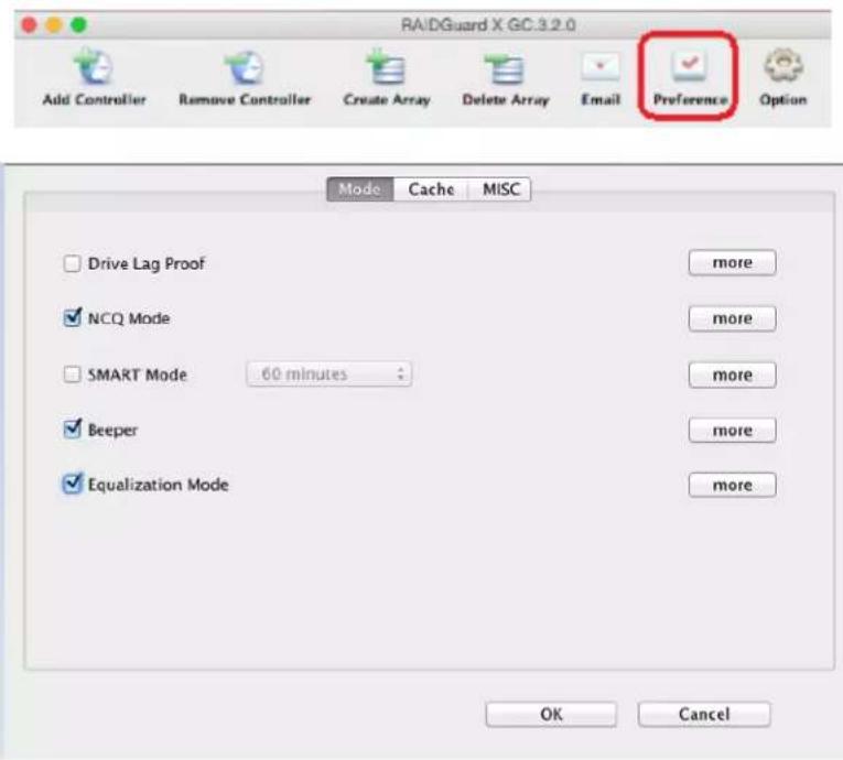
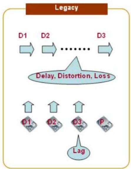
4.5.1 Disk Lag Proof
This feature ensures the stability and continuity of the RAID performance. In RAID 5 and RAID 6, DLP prevents the aging or slow responds of a single hard disk from influencing the overall performance. The advantage of this feature is making sure the data be protected if some hard disks fail to perform well.
flowchart
graph TD
    A["Legacy"] --> B["D1"]
    B --> C["D2"]
    C --> D["..."]
    D --> E["D3"]
    E --> F["Delay, Distortion, Loss"]
    F --> G["D1"]
    F --> H["D2"]
    F --> I["D3"]
    F --> J["P"]
    F --> K["Lag"]
flowchart
graph TD
    D1 --> D2 --> D3 --> D4 --> D5
    D3 --> FastDataRegeneration["Fast data regeneration"]
    D4 --> FastDataRegeneration
    D5 --> FastDataRegeneration
    FastDataRegeneration --> Lag[" Lag "]
    style D1 fill:#f9f,stroke:#333
    style D2 fill:#f9f,stroke:#333
    style D3 fill:#ccf,stroke:#333
    style D4 fill:#ccf,stroke:#333
    style D5 fill:#ccf,stroke:#333
    subgraph Fast data regeneration
        direction LR
        D1 <--> D2
        D2 <--> D3
        D3 <--> D4
        D4 <--> D5
        X["X"] --> D3
        P["P"] --> Lag
    end
In the event of performance degradation or delay of a single drive due to aging, the RAID system reads both data and parity stripes concurrently. It bypasses the slow reads and returns data to the host with the regenerated data and to provide stable performance based on the RAID parity.
Note
Slow response of some hard disks can be tolerated in DLP mode, you may use S.M.A.R.T. function to check the conditions of hard disks in an array and replace the faulty ones.
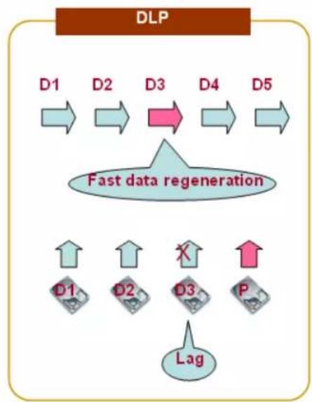
4.5.2 NCQ
Native Command Queuing (NCQ) is an extension of the Serial ATA protocol allowing hard disk drives to internally optimize the order in which received read and write commands are executed. This can reduce the amount of unnecessary drive head movement, resulting in increased performance (and slightly decreased wear of the drive) for workloads where multiple simultaneous read/write requests are outstanding.
The figure above illustrates the access sequence in NCQ and non-NCQ mode. The content sequences of the two hard disks are the same: 1, 2, 3, 4. However, the access sequence in NCQ mode may vary to improve the performance.
4.5.3 SMART Mode
S.M.A.R.T. is a monitoring system of disk drives to detect and report on various indicators of reliability, in the hope of anticipating failure. Accusys RAID system supports S.M.A.R.T. Once this function is selected, you can select the check interval from the drop-down list. Choose from 1 minute to 8 hours for SMART Mode to be active. The RAID controller will command each hard disk to perform S.M.A.R.T. according to the check interval selected. The check results will be shown as an Event message in the main menu.
When running S.M.A.R.T. mode, the performance of the system will be slightly affected. The higher the check frequency, the more the sequential accesses are affected. It is recommended to turn off S.M.A.R.T. if high performance required. On the other hand, running S.M.A.R.T. constantly allows you to monitor the conditions of hard disks at any time.
The options of time to check disk's S.M.A.R.T are 1,15,30,60 minutes and 2,4,8 hours. We strongly suggest set to 8 hours. Frequently checking will reduce the life time of hard drives
4.5.4 Beeper
To enable/disable system beeper, default is enabled.
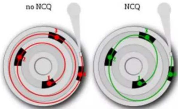
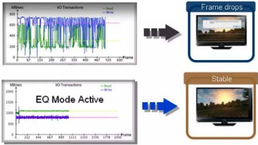
4.5.5 Equalization Mode
Regardless the transmission method, the data transmission speed cannot be guaranteed at all times. This feature allows the continuous I/Os to operate more smoothly and substantially reduce large fluctuations in efficiency during data transfer. For video editing, enable equalization to prevent video frame drops.
flowchart
graph TD
    A["Frame drops"] --> B["IEQ Mode Active"]
    B --> C["Stable"]
4.5.6 Cache
In this section, cache of RAID controller and drive can be configured by manual; default setting is tuned for video streaming application.
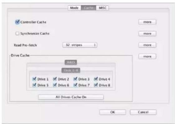
Controller Cache – Check this box to enable the controller cache. This speeds up the data transfer to and from the disks.
Caution
Data in cache may be erased if power down unexpected. Suggest using a UPS (uninterruptible power supply) to prevent this scenario.
Synchronize Cache – Check this box to enable cache synchronization with drives, to ensure all write data is correct, there is a frequently latency time within. For video capture, disable synchronization, because the video capture needs to be able to constantly write data to the RAID storage without long latency.
Read Pre-fetch – Identifies sequential access patterns and aggressively pre-fetches patterns into cache. From the drop down list, choose the number of stripes to pre-fetch. The default is 32; this is the recommended number.
Drive Cache – Choose which drives to cache. When more than one application accesses the database, the first applications cache needs to synchronize with the second. Each drive contains a built in write cache; checking these boxes chooses which drives to enable the caching on. Caching improves the efficiency and speed of data transfer.
All Drives Cache On/All Drives Cache Off – Click this button to enable/disable the caching on for all available drives.
Note
If Equalization mode enabled, Synchronize Cache and Read Prefetch will be disabled automatically.
4.5.7 MISC
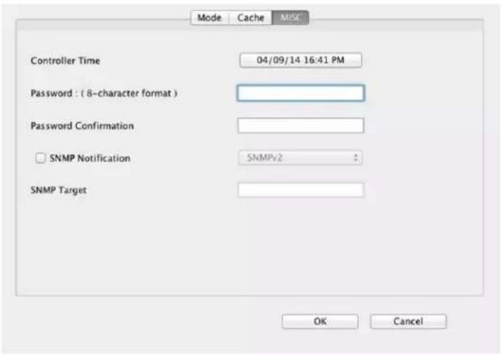
MSIC (Minimal Instruction Set Computer) has standard RAID controller time settings. The time of each event is displayed in the event logs in Event message.
Controller Time – Click this button to see a calendar and to change the time and date of the controller.
Password – Enter the new controller password. The default password is 00000000 (8 zeros). Type another 8 characters.
Password Confirmation – Confirm the new controller password.
Note:
If you forget your password, you will have to contact your agent or the Accusys Support Team.
SNMP Notification – Select SNMPv1 or SNMPv2 to send notifications for error conditions and possible problems to the SNMP servers. SNMP stands for Simple Network Management Protocol.
SNMP Target – Enter the IP address for sending the SNMP notifications.
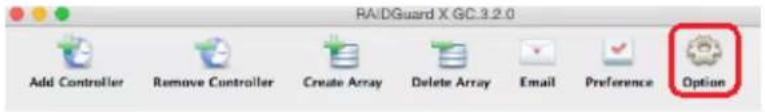
4.6 Option
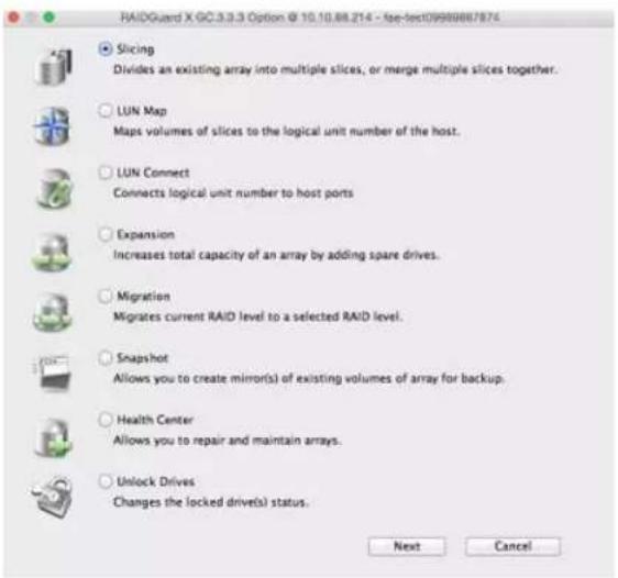
4.6.1 Slicing
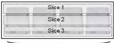
RAID slicing overcomes the inherent design of how data is stored on an drive or RAID system by subdividing a RAID array into segments, or slices. These slices are effective hardware partitions of all drives in the array. Each slice is a separate LUN and appears as a separate volume on the host computer. After slicing, the LUN map must be set for each slice.
RAID 5


Volume 1
Volume 2
Volume 3
(Video data)
(Footage)
(Audio)
Slicing concept
Usage Scenario:
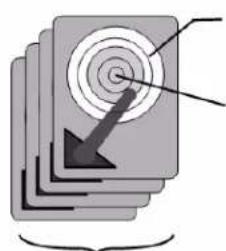
The access speed of the data stored in the outer circle is faster than the inner circle. Suppose there are two slices in a hard drive, Slice 0 locates in the outer circles while Slice 1 in the inner circle, for audio/video editing, you may store video data in Slice 0 and audio data in Slice 1.
natural_image
Stacked books with a spiral target and arrow icon, no visible text or symbolsSlice 0
(outer circle)
Slice 1 (inner circle)
RAID 5
Follow the steps below to select an array to slice or merge.
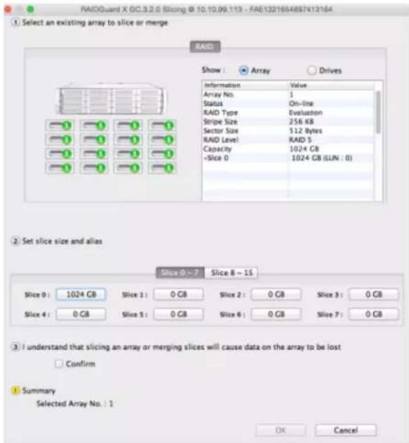
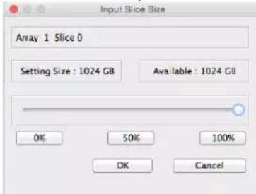
- Select the array by clicking on a drive with an array number. The capacity is displayed. By default, Slice 0 contains the entire capacity of the disk array.
- Click on Slice 0, use the slide bar or button of percentage to slice space and click OK to confirm. Repeat the same steps to slice more spaces if need.
Note
- Up to 16 slices per array.
- The total number of unique arrays' slices cannot exceed 16.
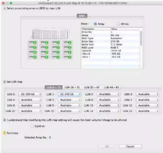
4.6.2 LUN Map
LUN, which stands for Logical Unit Number, is used to identify a logical unit in computer storage. When creating an array, you may select Assign LUN automatically to automatically assign a LUN to the new array. If Assign LUN automatically is not selected, you need to assign the LUN manually using LUN map.
Note
• One slice can only be assigned one LUN.
- Up to 64 LUNs
- Select the array to map by clicking on a drive with an array number.
- Choose a LUN and from the drop down list select a slice to map to, check the Confirm box and click OK.
- Repeat the steps to set more LUN maps if need.
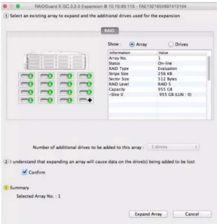
4.6.3 Expansion
Expansion adds spare disk to an existing array. This is no need to create a new array or stop an array; you may add new disks online while the array is in use, its performance is affected considerably. You may check the progress of Expansion in the main view.
Example:
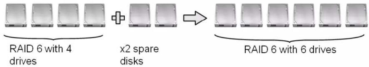
flowchart
graph LR
    A["RAID 6 with 4 drives"] --> C["x2 spare disks"]
    B["RAID 6 with 6 drives"] --> C
Note
The new hard drive must larger than the existing drives of array.
Follow the steps below to select an array to expand.
- Select the array to add additional drives, and select the number of drives to be added. A “+” sign appears above the drives to be added.
- Check the Confirm box and click Expand Array.
4.6.4 Migrations
Different from Expansion, which enlarges an array by adding hard drives to a fixed RAID level, Migration changes the RAID level of an array. It allows live changes to the RAID without the need to delete the array and rebuild. This can be useful when new drives have been added, and a new array type needs to be created.
Example 1:
RAID 5 (12 drives) -Migrating→ RAID 0 (>11 drives)
RAID 5 (12 drives) -Migrating→ RAID 6 (>13 drives)
RAID 5 (12 drives) -Migrating→ RAID 0+1 (>22 drives)
Example 2:
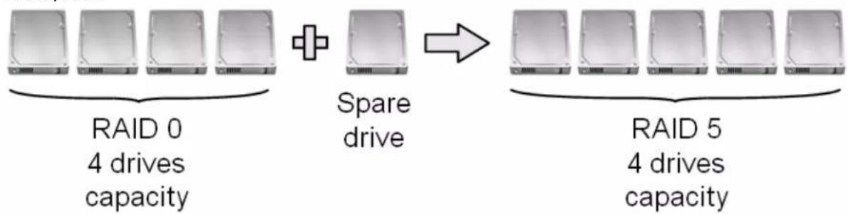
flowchart
graph LR
    A["RAID 0\n4 drives\ncapacity"] --> B["Spare drive"]
    B --> C["RAID 5\n4 drives\ncapacity"]
Example 3:
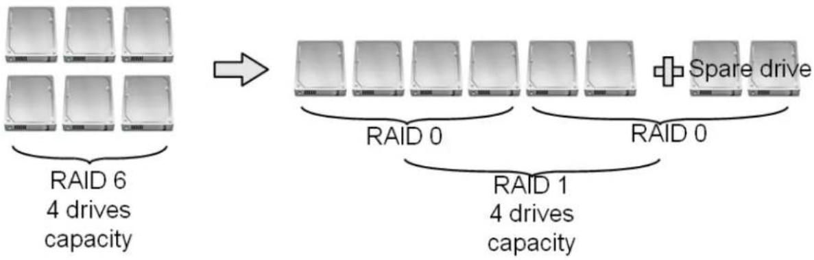
flowchart
graph TD
    A["RAID 6\n4 drives\ncapacity"] --> B["RAID 0"]
    B --> C["RAID 1\n4 drives\ncapacity"]
    C --> D["Spare drive"]
    style A fill:#f9f,stroke:#333
    style B fill:#ccf,stroke:#333
    style C fill:#cfc,stroke:#333
    style D fill:#fcc,stroke:#333
Note
The new hard drive must larger than the existing drives of array.
Follow the steps below to select an array to migrate. This changes the RAID level, such as from RAID 1 to RAID 5.
- Select the array to migrate. From the drop down menu, select the RAID level to migrate to, and then select the total number of drives to include in the array. A “+” appears above the drive(s) to be added, and a “-” sign above the drive(s) to be removed.
- Check the Confirm box and click Migrate.
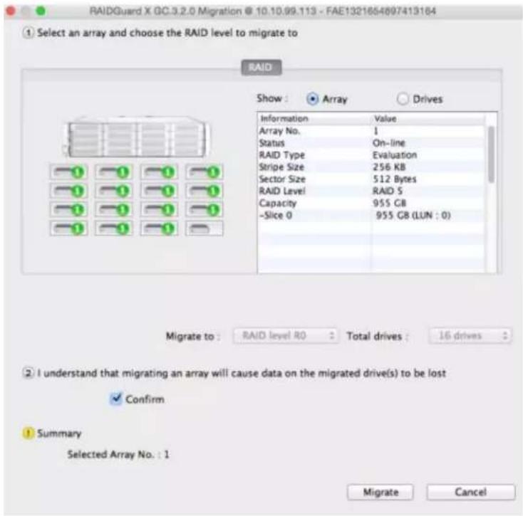
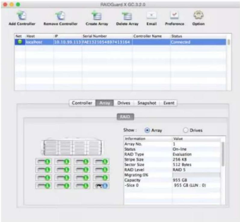
- The main array information screen will indicate that the array is currently migrating.
4.6.5 Snapshot
A snapshot is initialized with a data duplicate from a source to a target. The mirror snapshot is offered by the ExaSAN RAID controller.
Note
The source and target volume of the snapshot must be identical.
Before setting a snapshot, you need to set the slice in the array. The capacity of each slice and the number of shots should be in accordance with the space you need.
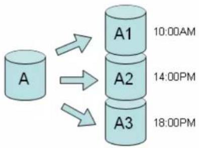
In the figure above, a snapshot can be created by splitting the source and target after the background sync is completed. The I/O mirroring is stopped, and the difference is under tracking in a bitmap table to support fast re-sync.
- One working volume with multiple snapshot volumes
- Snapshots are created at different point of time for the working volume
- Users can restore from any of snapshot volume at different point of time
flowchart
graph TD
    A["A"] --> A1["A1"]
    A --> A2["A2"]
    A --> A3["A3"]
    A1 -->|10:00AM| A1
    A2 -->|14:00PM| A2
    A3 -->|18:00PM| A3
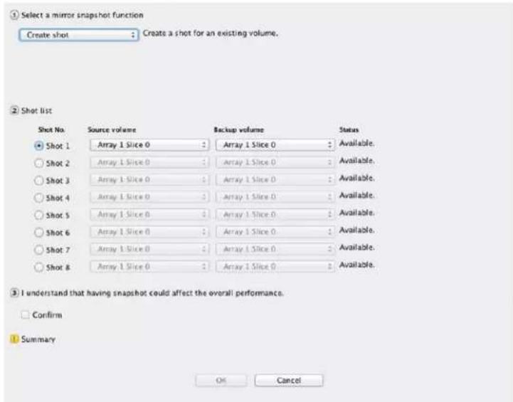
Create Shot
Create a snapshot of the selected slice. A maximum of 8 shots can be created. Once all shots have been used, older shots must be deleted before new ones can be taken.
- Select the Create Shot function from the drop down menu.
- Select the required shot by clicking on the Shot No. radio button. From the respective drop down menus, select the source volume and destination volume. Unavailable shots are grayed out.
- Check the Confirm box and click OK to take a snapshot.
Delete Shot
Delete the selected shot.
- Select the Delete Shot function from the drop down menu.
- Select the required shot by clicking on the Shot No. radio button. From the respective drop down menus, select the source volume and destination volume. Unavailable shots are grayed out.
- Check the Confirm box and click OK to delete a snapshot.
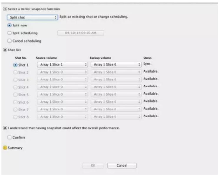
Split Shot
Split Now –
Split the selected shot or changes scheduling. The shot is split and read as two separate shots; therefore, it becomes two separate slices after being split.
- Select the Split Shot function from the drop down menu.
- Select the Split Now radio button.
- Select the required shot by clicking on the Shot No. radio button. From the respective drop down menus, select the source volume and destination volume. Unavailable shots are grayed out.
- Check the Confirm box and click OK to split the snapshot.
Split Scheduling –
Set any time to split shot.
- Select the Split Shot function from the drop down menu.
- Select the Split Scheduling radio button.
- Click on the time and date button to set split time.
- Select the required shot by clicking on the Shot No. radio button. From the respective drop down menus, select the source volume and destination volume. Unavailable shots are grayed out.
- Check the Confirm box and click OK to split the snapshot.
Cancel Scheduling –
Cancel the split shot scheduling.
- Select the Split Shot function from the drop down menu.
- Select the Cancel Scheduling radio button.
- Select the required shot by clicking on the Shot No. radio button. From the respective drop down menus, select the source volume and destination volume. Unavailable shots are grayed out.
- Check the Confirm box and click OK to split the snapshot.
Resynchronize Shot
Resynchronize the selected shot. This function can speed up mirroring for previous snapshots.
- Select the Resynchronize shot function from the drop down menu.
- Select the required shot by clicking on the Shot No. radio button. You can only select split shot for resynchronization.
- Check the Confirm box and click OK to split the snapshot.
Note
- The destination volume must be equal or larger in size than the source volume.
- The source volume and the destination volume can be on different arrays.
- The destination volume must NOT be mapped to a LUN.
- A shot will not be deleted if the details of the array change. The only way to delete a shot is using the Delete Shot function under Snapshot.
4.6.6 Health Center
To ensure the accuracy of the RAID parity data, RAID controller offers Background checking and "Rebuild parity data". During checking or rebuilding parity, the performance of the array will be affected. You may check the progress in the Main view or in the Health Center.
Follow the steps below to select an array to verify, rebuild, or condition.
- Select the Array to verify, rebuild, or condition.
- Click the radio button to:
Rebuild the parity data – Rebuilding parity on an array uses the data on the array to create new parity data, no repair problems with the data.
Verify the parity data – Verify that the data is free of errors.
Refresh array data and parity – Select the priority between Low, Med., or High. This process scans, rewrites, and scrubs bad data conditions caused by excessive vibration during drive I/Os, or data degradation caused by Adjacent Track Interference (ATI).
- Click OK to start the operation.
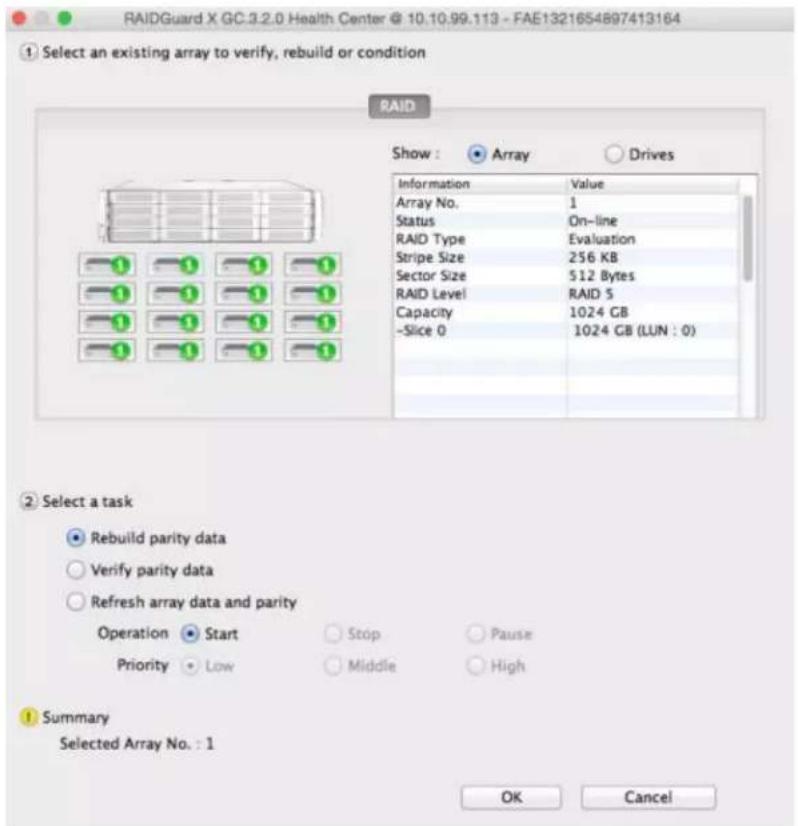
- The main array information screen will indicate that the array is undergoing rebuilding, verification, or refreshing.
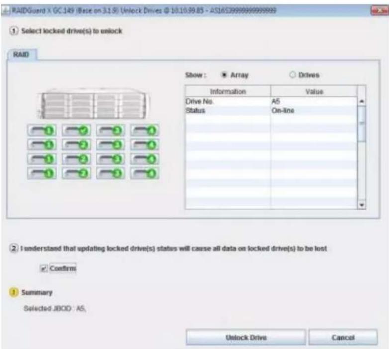
4.6.7 Unlock Drives
The RAID controller may lock abnormal drives in an array. You may unlock these drives and rejoin them in an array. Drives may be locked with one of two conditions:
- If a drive returns data too slowly, the controller determines the drive is experiencing a failure and executes Drive Drop. When you unlock the drive, it will be added directly to the array if there has not been drive access during the locked period. Otherwise, the controller will rebuild parity data on the drive when the drive is online.
Note
If "Drive Drop" occurs, it is recommended to use S.M.A.R.T. to check the drive condition and replace it if necessary.
- When a drive has been used by RAID system, that drive will be locked if insert it to another RAID system.
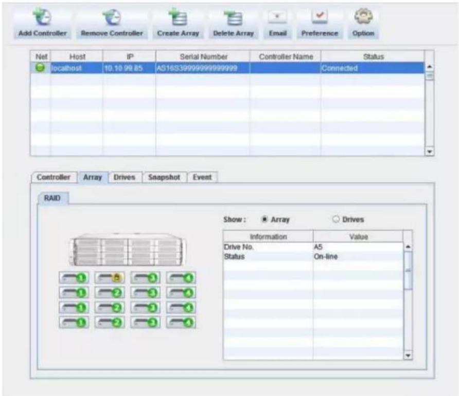
Follow the steps below to select a drive to unlock.
- Select the drive with the icon. It will change to the icon.

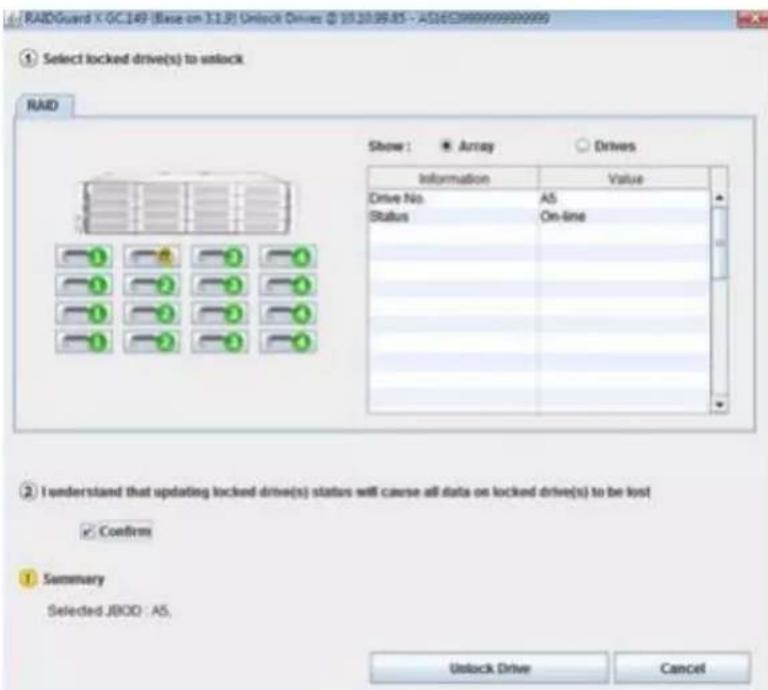
- Check the Confirm box and click Unlock Drive.
4.7 Updating the ExaSAN RAID system Firmware
Follow the steps in this section to update the firmware of your RAID system.
- Note the current firmware version (System Code, Boot Code, Expander Code, etc) from RAIDGuardX.
- Download the latest firmware from website www.accusys.com.tw/support/download.htm.
Caution
- Do NOT writing data, shutdown, interrupt RAID system during updating, in order to avoid any damage.
-
Firmware update time will take in 5 minutes.
-
Select Controller in the Menu bar, move to Update > Update System Code in drop menu.
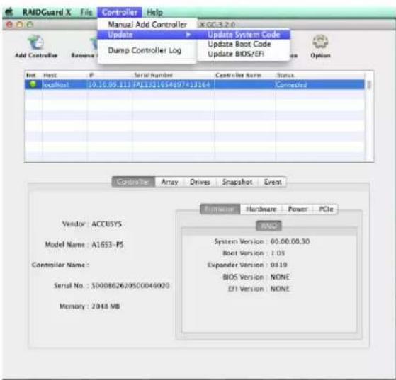
- Choose correct System Code file to start updating. During the update process, the RAID system will stop all data access.
Caution
Do NOT interrupt or stop updates that are in progress. Firmware update time will take in 2\~5 minutes.
-
Once the update is complete, make sure to restart (power off / on) the RAID system to make new firmware available.
-
Repeat the steps to update other firmware.
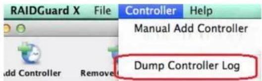
4.8 Download controller log
Download the event log for troubleshooting by pressing Dump Controller Log, log file (zip) will be saved at RAIDGuardX installed folder,
Default folder to save log file:
MAC: /Application/RAIDGuardX/Log
Windows: /Program Files/Accusys/RAIDGuardX/Log
Linux:/{GC folder}/log
4.9 Disk RW Test
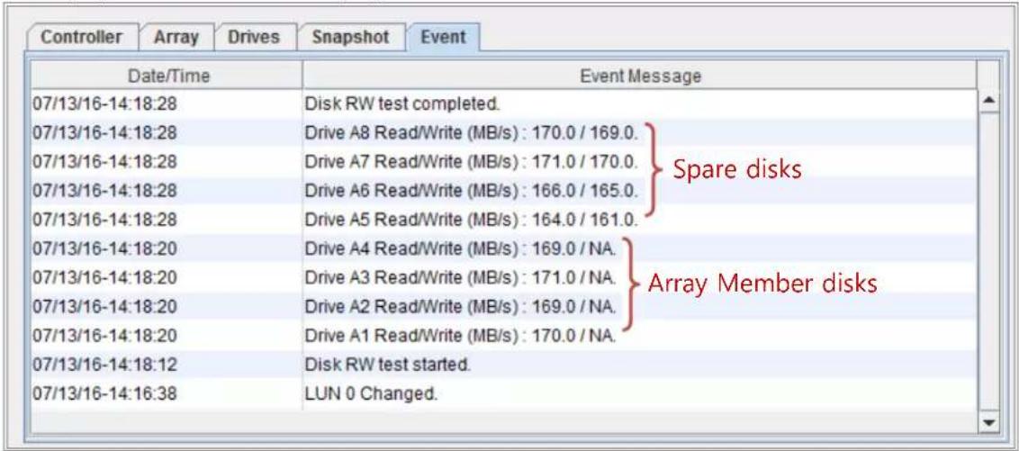
Read/Write throughput is highly depending on the condition of disk inserted in RAID system. When one of disks begins to drop down in Read/Write, the entire RAID system would slow down, and sometimes SMART function cannot figure out which one is the slow disk; Disk RW Test funtion executes read/write test on each disk and list the result on Event page for reference. User can replace the slowest disk to improve the whole system performance.
When performing Disk RW Test,
- All disks in RAID/JBOD enclosures would be individually executed sequentially in a few seconds
- Both read/write test on all spare disk
- ONLY read test on all array member disk
Requirements
System Code version 3.4.1 and later
RAIDGuardX version 3.4.1 and later
Executing Disk RW Test
- Stop IO access into RAID system
- Click RAIDGuardX > Tab/Controller > Disk RW test
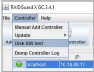
- Click Yes on dialog window
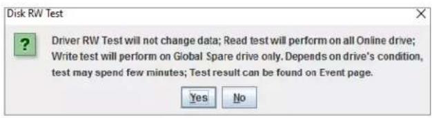
3. Display test result on Event page
5. RAID Overview
5. RAID Overview
5.1 How RAID Works
RAID, or Redundant Array of Independent Disks, is a data-storage technology that spreads data across multiple drives. This technology provides several benefits
• Data redundancy for protection and availability
- Higher performance as a result of reading or writing on several drives simultaneously
- Scalability for expansion of storage
Accusys RAID systems use a hardware controller to manage multiple drives as one or more RAID array group, which offloads RAID task from host, provides independent, fast and highly efficient storage.
flowchart
graph LR
    A["Four DC drives"] --> B["Reset/Recycle"]
    B --> C["Single hard drive"]
The way of controller stores and retrieves data on the RAID system is determined by the RAID level and storage method you choose. Once you have defined a group of drives as an array group, the controller groups those drives into logical disk, each logical disk appears to the host system as one Logical Unit (LUN), regardless of the number of actual drives in that logical unit.
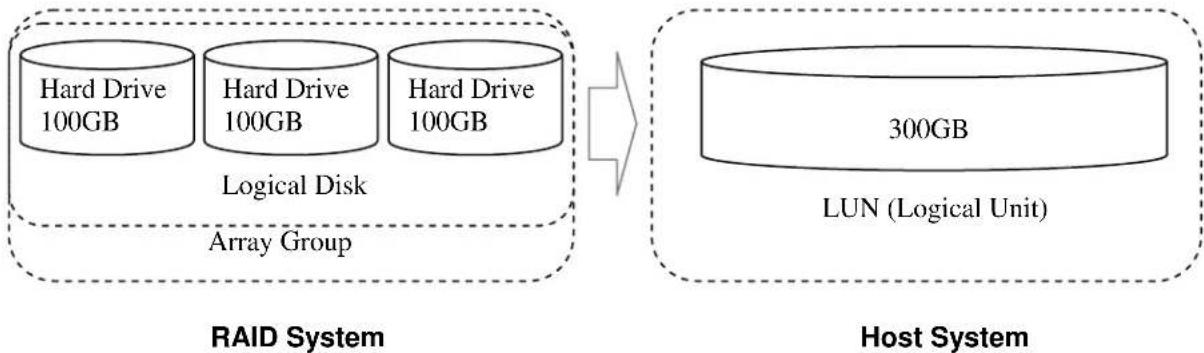
flowchart
graph LR
    subgraph RAID System
        A["Hard Drive 100GB"] --> B["Logical Disk"]
        C["Hard Drive 100GB"] --> B
        D["Hard Drive 100GB"] --> B
        E["Array Group"] --> B
    end

    subgraph Host System
        F["300GB"] --> G["LUN (Logical Unit)"]
    end

    style RAID System fill:#f9f9f9,stroke-dasharray: 5 5
    style Host System fill:#f9f9f9,stroke-dasharray: 5 5
5.2 RAID Levels
The RAID system supports several RAID levels and configurations. Each level has a different architecture and provides varying degrees of performance and fault tolerance.
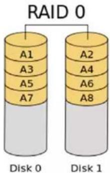
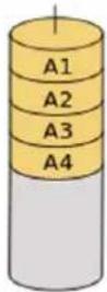
5.2.1 RAID 0: Striping
RAID level 0, striping only, is the fastest and most efficient array type, but offer no fault-tolerance. Any drive failure destroys the data in the array.
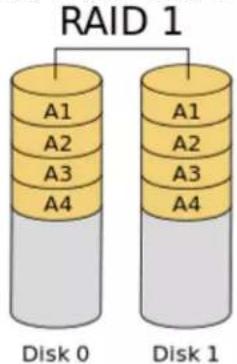
5.2.2 RAID 1: Mirroring
RAID level 1, mirroring, each drive stores identical data. RAID 1 provides very high data reliability and improved performance for read-intensive applications, but this level has a high capacity cost because it retains a full copy of your data on each drive in mirror set.
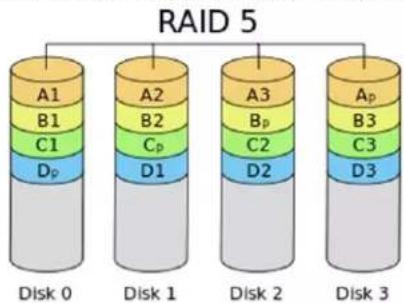
5.2.3 RAID 5: Striping disks with distributed parity
By distributing the parity information across all drives in a set, RAID level 5 achieves high reliability and data availability, which allows one of array member disk get failure and keeps storage work. Disk failure has a moderate impact on the total transfer rate.
5.2.4 RAID 6: Independent data disks with two Independent parity schemes
RAID level 6 extends RAID level 5 by adding an additional parity block; thus it uses block-level striping with two parity blocks distributed across all member disks. RAID 6 allows two of array member disk get failure at the same time and keeps storage work.
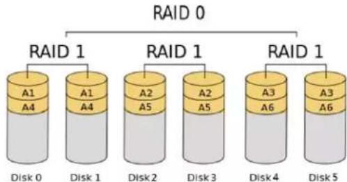
5.2.5 RAID 0+1: Striped set with Mirroring
RAID 0+1 combines the advantages of RAID 0 and RAID 1 with none of the disadvantages. RAID 0+1 creates a mirror of the primary striped set. RAID 0+1 provides optimal speed and reliability.
flowchart
graph TD
    A["RAID 0"] --> B["RAID 1"]
    B --> C["A1 A4"]
    B --> D["A1 A4"]
    B --> E["RAID 1"]
    E --> F["A2 A5"]
    E --> G["A2 A5"]
    E --> H["RAID 1"]
    H --> I["A3 A6"]
    H --> J["RAID 1"]
    J --> K["A3 A6"]
    style A fill:#f9f,stroke:#333
    style B fill:#ccf,stroke:#333
    style C fill:#cfc,stroke:#333
    style D fill:#cfc,stroke:#333
    style E fill:#cfc,stroke:#333
    style F fill:#cfc,stroke:#333
    style G fill:#cfc,stroke:#333
    style H fill:#cfc,stroke:#333
    style I fill:#cfc,stroke:#333
    style J fill:#cfc,stroke:#333
    style K fill:#cfc,stroke:#333
5.2.6 Enhance JBOD: Single disk
Enhance JBOD is just export single disk to host system. Capacity, speed is same as original single disk.
Enhance JBOD
| RAID Level | Data Format | Minimum Drive | Total Capacity (N = number of drive) | Redundancy | Performance |
| RAID0 | Stripe | 2 | Single Drive * N | None | High |
| RAID1 | Mirror | 2 | Single Drive * 1 | N – 1 | Low |
| RAID5 | Stripe with 1 Parity | 3 | Single Drive * (N-1) | 1 | Medium |
| RAID6 | Stripe with 2 Paries | 4 | Single Drive * (N-2) | 2 | Medium |
| RAID 0+1 | Stripe + Mirror | 4 | Single Drive * (N/2) | 2 | Low |
| Enhance JBOD | Single Drive | 1 | Single Drive * 1 | None | Low |
- Appendices
Appendix A: FAQs
- Q: I have created an RAID 5 array in RAIDGuardX, but host does not find the array volume, any solution?
A: Please check as steps below;
I. Go to GUI page 'Options > LUN Mapping' to ensure the array has been mapped to a LUN
II. Restart RAID system, to avoid the driver is not ready.
III. Format array volume to which format type you desired, then new volume would appear;
On MAC: /Applications/DiskUtility
On Windows: in Disk Management console
On Linux: use fdisk command
# fdisk -l
- Q: I moved my A16S3-PS to another computer with the same Z2M, Cable and RAID system, but disk volume does not appear on this computer, any solution?
A: Please check as steps below;
I. Make sure RAID system is boot up ready (all front LEDs light blue; green heartbeat LED of controller is flashing).
II. Make sure the link LED of Z2M is correct.
III. Ensure the QSFP cable is connected securely. You would hear a "click" sound when connected cable to connector of host and storage.
IV. Ensure cable connected to correct port of Z2M; DAS port is for connecting storage directly, SAN port is for connecting to ExaSAN switch.
V. Make sure the driver is running well;
VI. If the problem cannot be fixed, it might be a compatibility issue. Ask for technical support to your reseller, or send email to support@accusys.com.tw and briefly describe the problem. Be sure to include the driver error code, the motherboard (or host) model and the OS version, we would help to resolve the issue.
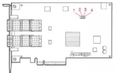
3. Q: What does four internal LEDs of Z2M mean?
A: these LEDs indicate the link status of the HBA, refer to user guide (http://www.accusys.com.tw/Document/HBA_Cable/Z2M_G3_QSG_20141216.pdf) for more detail;
LED 1: HBA properly link with the PCIe slot of main board
LED 2: The upper QSFP connector is active as SAN mode
LED 3: The lower QSFP connector is active as DAS mode
LED 4: The HBA card is failure, disconnected from host computer
4. Q: On Windows, a dialog "Find no RAID card" appears when boot up, how can this be resolved?
A: Please check as steps below;
I. Reload RAIDGuardX Server with Administrator permission, or disable User Account Control (UAC) protection.
II. Make sure RAID system is boot up ready (all front LEDs light blue; green heartbeat LED of controller is flashing).
III. Make sure the link LED of Z2M is correct.
IV. Ensure the QSFP cable is connected securely. You would hear a "click" sound when connected cable to connector of host and storage.
V. Ensure cable connected to correct port of Z2M; DAS port is for connecting storage directly, SAN port is for connecting to ExaSAN switch.
VI. Make sure the driver is running well;
VII. If the problem cannot be fixed, it might be a compatibility issue. Ask for technical support to your reseller, or send email to support@accusys.com.tw and briefly describe the problem. Be sure to include the driver error code, the motherboard (or host) model and the OS version, we would help to resolve the issue.
5. Q: On a MAC host, to open RAIDGuardX and press Add Controller icon, but there is no controller on list, how can this be resolved?
A: Please check as steps below;
I. Check if Accusys driver is up. ("Utilities > System Information> Software > Extensions", ACS6x.kext should list.)
II. Reload RAID GuardX Server by double click DTRGuiSrv01_64 on path /Libaray/StartupItems/ RGX_Accusys.
III. Make sure RAID system is boot up ready (all front LEDs light blue; green heartbeat LED of controller is flashing).
IV. Make sure the link LED of Z2M is correct.
V. Ensure the QSFP cable is connected securely. You would hear a "click" sound when connected cable to connector of host and storage.
VI. Ensure cable connected to correct port of Z2M; DAS port is for connecting storage directly, SAN port is for connecting to ExaSAN switch.
VII. Make sure the driver is running well;
VIII. If the problem cannot be fixed, it might be a compatibility issue. Ask for technical support to your reseller, or send email to support@accusys.com.tw and briefly describe the problem. Be sure to include the driver error code, the motherboard (or host) model and the OS version, we would help to resolve the issue.
- Q: Why doesn't the performance reach the expected levels while testing the A16S3-PS? Why isn't the performance steady enough?
A: If the performance is unsteady or not achieving the expected level, in many cases, the Drive is the cause. It is strongly recommended to use the enterprise level Drive.
- Q: When inserting a drive into A16S3-PS, in RAIDGuardX, this drive shows in Locked mode and system start issue 3 short bi repeatedly, what does it mean?
A: It indicates this drive has been used in another Accusys RAID system and contains a portion of RAID data. If data is not important, unlock the drive in RAIDGuardX > Options > Unlock, it would become a new global drive.
- Q: I exchanged my original computer to a new one, with the same HBA, Cable and RAID system, but disk volume does not appear, any solution?
A: it could be hardware or compatible issue, please check as steps below;
a. Ensure the QSFP cable is connected securely. You should be able to hear a "click" sound when you connect the cable to the connector.
b. Please check the connection port is correct. DAS is for host directly, SAN is for connecting to ExaSAN switches.
c. Please check if the installer and the driver have been installed correctly. If the installation has completed and the error still persists, it may be a compatibility issue. Send an email to support@accusys.com.tw and briefly describe the problem. Be sure to include the driver error code, the motherboard (or host) model name and the OS. We will contact you to assist you in resolving the issue.
- Q: How do I know the meaning of all beeper alerts?
A: Below table is the Beeper Code.
| Beeper mode | Description |
| 1 short beep (boot up) | RAID system is ready |
| 1 short beep | Array init, rebuild, expansion, migratrion |
| 2 short beeps | Wrong ID setting of JBOD enclosure |
| 3 short beeps | Error of Fan, Power, RAID or Disk locked |
| 1 long beep | System Panic |
Appendix B: Customer Service and Support
C.1 System Log
When you contact us for technical support, our support staff might ask for your system log file for troubleshooting purpose.
1) RAID controller log by Dump controller log of RAIDGuard X
2) Client operation system log. (it's better to record related error message.)
C.2 Contact Us
Email us for customer services and technical support;
Sales: sales@accusys.com.tw
Technical Support: support@accusys.com.tw
C.3 Our Website
Please visit our websites frequently for the most up-to-date product and support information.
All countries: www.accusys.com.tw
Korea: http://accusys.co.kr