
XVR5208AN-4KL-I2 - Video recorder Dahua Technology - Free user manual and instructions
Find the device manual for free XVR5208AN-4KL-I2 Dahua Technology in PDF.


| Product Type | Video Recorder (DVR) |
| Model | XVR5208AN-4KL-I2 |
| Brand | Dahua Technology |
| Video Input | 8 channels BNC (analog) + IP cameras |
| Compression Format | H.265, H.264, G.711 audio |
| AI Functions | Face detection, face recognition, IVS (tripwire, intrusion), people counting, vehicle detection |
| Recording Resolution | Up to 4K (3840x2160) for IP channels, 1080p for analog |
| Storage | Up to 2 SATA HDDs (max 10TB each) |
| Power Supply | 12 VDC, 2A (typical) |
| Dimensions (approx.) | 300 x 250 x 50 mm |
| Weight (approx.) | 2.5 kg (without HDD) |
| Video Output | HDMI (4K), VGA, BNC (CVBS) |
| Audio | 1 audio input (BNC), 1 audio output (BNC), two-way talk |
| Alarm I/O | 16 alarm inputs, 3 alarm outputs (NO/NC) |
| Network | 1 Ethernet port (10/100/1000 Mbps) |
| PTZ Control | RS-485, supports multiple protocols |
| Backup Interface | USB 2.0, eSATA |
| Operating Temperature | -10°C to +55°C |
| Security Features | Password protection, account lock, HTTPS, IP filtering |
| Maintenance | Keep ventilated, avoid dust and moisture; update firmware regularly |
Frequently Asked Questions - XVR5208AN-4KL-I2 Dahua Technology
User questions about XVR5208AN-4KL-I2 Dahua Technology
0 question about this device. Answer the ones you know or ask your own.
Ask a new question about this device
Download the instructions for your Video recorder in PDF format for free! Find your manual XVR5208AN-4KL-I2 - Dahua Technology and take your electronic device back in hand. On this page are published all the documents necessary for the use of your device. XVR5208AN-4KL-I2 by Dahua Technology.
USER MANUAL XVR5208AN-4KL-I2 Dahua Technology
AI Digital Video Recorder User's Manual

natural_image
Abstract geometric composition with gray and red color blocks (no text or symbols)Foreword
General
This user's manual (hereinafter referred to be "the Manual") introduces the functions and operations of the DVR devices (hereinafter referred to as "the Device"). Read carefully before using the device, and keep the manual safe for future reference.
Safety Instructions
The following signal words might appear in the manual.
| Signal Words Meaning | |
 DANGER DANGER | Indicates a high potential hazard which, if not avoided, will result in death or serious injury. |
 WARNING WARNING | Indicates a medium or low potential hazard which, if not avoided, could result in slight or moderate injury. |
 CAUTION CAUTION | Indicates a potential risk which, if not avoided, could result in property damage, data loss, reductions in performance, or unpredictable results. |
 TIPS TIPS | Provides methods to help you solve a problem or save time. |
 NOTE NOTE | Provides additional information as a supplement to the text. |
Revision History
| Version | Revision Content | Release Time |
| V2.3.0 | Added DH-XVR54xxL-4KL-I3, DH-XVR58xxS-4KL-I3, DH-XVR58xxS-4KL-I3-LP, DH-XVR71xxH-4K-I3, DH-XVR71xxHE-4K-I3, DH-XVR72xxA-4K-I3, DH-XVR72xxAN-4K-I3, DH-XVR74xxL-4K-I3, and DH-XVR78xxS-4K-I3. | July 2022 |
| V2.2.0 | Added the configuration of extended smart illumination. | June 2022 |
| V2.1.0 | Added DH-XVR54xxL-I3 and DH-XVR58xxS-I3. | May 2022 |
| V2.0.0 | Added DH-XVR42xxAN-I(V2.0).Added smart illumination as alarm linkage.Added schedule mode for AI functions.Added IVS mode switch.Added disabling event notifications in disarming.Added sensitivity for IVS settings.Updated disk quota.Supports safety baseline 2.0. | April 2022 |
| V1.2.1 | Updated AI mode switch.Added intelligent diagnosis.Updated alarm-in port settings.Updated password resetting. | December 2021 |
| V1.2.0 Added some models. | October 2021 | |
| V1.1.0 | Added DH-XVR4232AN-I. | July 2021 |
| V1.0.11 | Added DH-XVR5816S-4KL-I2-LP and DH-XVR7816S-4KL-X-LP-V2. | May 2021 |
| V1.0.10 Deleted the video quality analytics function. | April 2021 | |
| V1.0.9 Added some models. | February 2021 | |
| V1.0.8 Added some models. | November 2020 | |
| V1.0.7 Added some models. | September 2020 | |
| V1.0.6 Added some models. | May 2020 | |
| V1.0.5 | Updated to 4.0 UI version. | February 2020 |
| V1.0.4 | Added disarm function, HDD database function, and SMD preview function.Optimizes Smart Search function, available to filtering human and vehicle. | September 2019 |
| V1.0.0 | First release. | October 2018 |
Privacy Protection Notice
As the device user or data controller, you might collect the personal data of others such as their face, fingerprints, and license plate number. You need to be in compliance with your local privacy protection laws and regulations to protect the legitimate rights and interests of other people by implementing measures which include but are not limited: Providing clear and visible identification to inform people of the existence of the surveillance area and provide required contact information.
About the Manual
- The manual is for reference only. Slight differences might be found between the manual and the product.
- We are not liable for losses incurred due to operating the product in ways that are not in compliance with the manual.
- The manual will be updated according to the latest laws and regulations of related jurisdictions. For detailed information, see the paper user's manual, use our CD-ROM, scan the QR code or visit our official website. The manual is for reference only. Slight differences might be found between the electronic version and the paper version.
- All designs and software are subject to change without prior written notice. Product updates might result in some differences appearing between the actual product and the manual. Please contact customer service for the latest program and supplementary documentation.
- There might be errors in the print or deviations in the description of the functions, operations and technical data. If there is any doubt or dispute, we reserve the right of final explanation.
- Upgrade the reader software or try other mainstream reader software if the manual (in PDF format) cannot be opened.
- All trademarks, registered trademarks and company names in the manual are properties of their respective owners.
- Please visit our website, contact the supplier or customer service if any problems occur while using the device.
- If there is any uncertainty or controversy, we reserve the right of final explanation.
Important Safeguards and Warnings
This chapter describes the contents covering proper handling of the Device, hazard prevention, and prevention of property damage. Read carefully before using the device, and comply with the guidelines when using it.
Operation Requirements
- Do not place or install the Device in a place exposed to sunlight or near the heat source.
- Keep the Device away from dampness, dust or soot.
- Keep the Device installed horizontally on the stable place to prevent it from falling.
• Wall-mounting is not supported. - Do not drop or splash liquid onto the Device, and make sure there is no object filled with liquid on the Device to prevent liquid from flowing into the Device.
● Install the Device in a well-ventilated place, and do not block the ventilation of the Device. - Operate the device within the rated range of power input and output.
- Do not dissemble the Device.
● Transport, use and store the Device under the allowed humidity and temperature conditions.
Electrical Safety
- Use the battery of specified manufacturer; otherwise there might result in explosion. When replacing battery, make sure the same type is used. Improper battery use might result in fire, explosion, or inflammation.
- Follow the instructions to dispose of the used battery.
- Use the recommended power cables in the region and conform to the rated power specification.
- Use the power adapter provided with the Device, or adapter meets the LPS standard; otherwise, it might result in people injury and device damage.
- The power supply must conform to the requirements of ES1 in IEC 62368-1 standard and be no higher than PS2. Note that the power supply requirements are subject to the device label.
- Connect the device (I-type structure) to the power socket with protective earthing.
- The appliance coupler is a disconnection device. When using the coupler, keep the angle for easy operation.
Table of Contents
Foreword....II
Important Safeguards and Warnings......V
1 Introduction.... 1
1.1 Overview ...... 1
1.2 Functions....1
2 Getting Started.... 3
2.1 Checking the Components .... 3
2.2 Installing HDD .... 3
2.2.1 DH-XVR42xxAN-I/DH-XVR42xxAN-I(V2.0)/DH-XVR52xxA-I2/DH-XVR52xxA-I3/DH-XVR52xxA-4KL-I2/DH-XVR52xxA-4KL-I3/DH-XVR52xxAN-I2/DH-XVR52xxAN-I3/DH-XVR52xxAN-4KL-I2/DH-XVR52xxAN-4KL-I3/DH-XVR72xxA-4K-I2/DH-XVR72xxA-4K-I3/DH-XVR72xxA-4KL-I/DH-XVR72xxAN-4K-I2/DH-XVR72xxAN-4K-I3/DH-XVR82xxA-4K-I/DH-XVR82xxA-4KL-I....4
2.2.2 DH-XVR58xxS-I2/DH-XVR58xxS-4KL-I2/DH-XVR58xxS-4KL-I2-LP/DH-XVR58xxS-I3/DH-XVR58xxS-4KL-I3/DH-XVR58xxS-4KL-I3-LP/DH-XVR78xxS-4K-I2/DH-XVR78xxS-4K-I3/DH-XVR78xxS-4KL-X-LP-V2/DH-XVR88xxS-4KL-I....6
2.2.3 DH-XVR54xxL-I2/DH-XVR54xxL-4KL-I2/DH-XVR54xxL-I3/DH-XVR54xxL-4KL-I3/DH-XVR74xxL-4K-I2/DH-XVR74xxL-4K-I3....8
2.2.4 DH-XVR1Bxx-I/DH-XVR1BxxH-I/DH-XVR41xxC-I/DH-XVR41xxHS-I/DH-XVR51xxH-I/DH-XVR51xxH-I2/DH-XVR51xxH-I3/DH-XVR51xxH-4KL-I2/DH-XVR51xxH-4KL-I3/DH-XVR51xxHE-I2/DH-XVR51xxHE-I3/DH-XVR51xxHE-4KL-I2/DH-XVR51xxHE-4KL-I3/DH-XVR51xxHS-I2/DH-XVR51xxHS-I3/DH-XVR51xxHS-4KL-I2/DH-XVR51xxHS-4KL-I3/DH-XVR71xxH-4K-I2/DH-XVR71xxH-4K-I3/DH-XVR71xxHE-4KL-I/DH-XVR71xxHE-4K-I2/DH-XVR71xxHE-4K-I3....11
2.2.5 DH-XVR51xxC-I3/DH-XVR51xxC-4KL-I3....13
3 The Grand Tour 16
3.1 Front Panel....16
3.1.1 DH-XVR51xxH-I....16
3.1.2 DH-XVR71xxH-4K-I2/DH-XVR71xxH-4K-I3/DH-XVR71xxHE-4K-I2/DH-XVR71xxHE-4K-I3/DH-XVR71xxHE-4KL-I....16
3.1.3 DH-XVR72xxA-4KL-I/DH-XVR72xxAN-4K-I2/DH-XVR72xxA-4K-I2/DH-XVR72xxAN-4K-I3/DH-XVR72xxA-4K-I3....17
3.1.4 DH-XVR82xxA-4K-I/DH-XVR82xxA-4KL-I....17
3.1.5 DH-XVR41xxC-I/DH-XVR41xxHS-I/DH-XVR42xxAN-I/DH-XVR42xxAN-I(V2.0)/DH-XVR51xxH-I2/DH-XVR51xxH-I3/DH-XVR51xxH-4KL-I2/DH-XVR51xxH-4KL-I3/DH-XVR51xxHE-I2/DH-XVR51xxHE-I3/DH-XVR51xxHE-4KL-I2/DH-XVR51xxHE-4KL-I3/DH-XVR51xxHS-I2/DH-XVR51xxHS-I3/DH-XVR51xxHS-4KL-I2/DH-XVR51xxHS-4KL-I3/DH-XVR52xxA-I2/DH-XVR52xxA-I3/DH-XVR52xxA-4KL-I2/DH-XVR52xxA-4KL-I3/DH-XVR52xxAN-I2/DH-XVR52xxAN-I3/DH-XVR52xxAN-4KL-I2/DH-XVR52xxAN-4KL-I3....18
3.1.6 DH-XVR78xxS-4K-I2/DH-XVR78xxS-4K-I3/DH-XVR78xxS-4KL-X-LP-V2/DH-XVR88xxS-4KL-I.....19
3.1.7 DH-XVR74xxL-4K-I2/DH-XVR74xxL-4K-I3 19
3.1.8 DH-XVR54xxL-I2/DH-XVR54xxL-4KL-I2/DH-XVR54xxL-I3/DH-XVR54xxL-4KL-I3....20
3.1.9 DH-XVR58xxS-I2/DH-XVR58xxS-I3/DH-XVR58xxS-4KL-I2/DH-XVR58xxS-4KL-I3/DH-XVR58xxS-4KL-I2-LP/DH-XVR58xxS-4KL-I3-LP 20
3.1.10 DH-XVR1Bxx-I/DH-XVR1BxxH-I.....21
3.1.11 DH-XVR51xxC-I3/DH-XVR51xxC-4KL-I3....21
3.2 Rear Panel 22
3.2.1 DH-XVR51xxH-I/DH-XVR51xxH-I2/DH-XVR51xxH-I3/DH-XVR51xxH-4KL-I2/DH-XVR51xxH-4KL-I3/DH-XVR51xxHE-I2/DH-XVR51xxHE-I3/DH-XVR51xxHE-4KL-I2/DH-XVR51xxHE-4KL-I3/DH-XVR71xxH-4K-I2/DH-XVR71xxH-4K-I3/DH-XVR71xxHE-4K-I2/DH-XVR71xxHE-4K-I3/DH-XVR71xxHE-4KL-I....22
3.2.2 DH-XVR41xxC-I/DH-XVR41xxHS-I/DH-XVR51xxHS-I2/DH-XVR51xxHS-I3/DH-XVR51xxHS-4KL-I2/DH-XVR51xxHS-4KL-I3....23
3.2.3 DH-XVR52xxA-I2/DH-XVR52xxA-I3/DH-XVR52xxA-4KL-I2/DH-XVR52xxA-4KL-I3/DHXVR42xxAN-I/DH-XVR42xxAN-I(V2.0)/DH-XVR52xxAN-I2/DH-XVR52xxAN-I3/DH-XVR52xxAN-4KL-I2/DH-XVR52xxAN-4KL-I3/DH-XVR72xxA-4K-I2/DH-XVR72xxA-4K-I3/DH-XVR72xxA-4KL-I/DH-XVR72xxAN-4K-I2/DH-XVR72xxAN-4K-I3....24
3.2.4 DH-XVR82xxA-4K-I/DH-XVR82xxA-4KL-I 26
3.2.5 DH-XVR58xxS-I2/DH-XVR58xxS-4KL-I2/DH-XVR58xxS-I3/DH-XVR58xxS-4KL-I3/DH-XVR78xxS-4K-I2/DH-XVR78xxS-4K-I3/DH-XVR88xxS-4KL-I.....27
3.2.6 DH-XVR58xxS-4KL-I2-LP/DH-XVR58xxS-4KL-I3-LP/DH-XVR78xxS-4KL-X-LP-V2....29
3.2.7 DH-XVR54xxL-I2/DH-XVR54xxL-4KL-I2/DH-XVR54xxL-I3/DH-XVR54xxL-4KL-I3/DH-XVR74xxL-4K-I2/DH-XVR74xxL-4K-I3 31
3.2.8 DH-XVR1Bxx-I/DH-XVR1BxxH-I....33
3.2.9 DH-XVR51xxC-I3/DH-XVR51xxC-4KL-I3 34
3.3 Remote Control Operations....34
3.4 Mouse Operations 36
4 Connection.... 38
4.1 Typical Connection Diagram....38
4.2 Connecting to Video and Audio Input and Output....38
4.2.1 Video Input....38
4.2.2 Video Output ....39
4.2.3 Audio Input 39
4.2.4 Audio Output ....39
4.3 Connecting to Alarm Input and Output....40
4.3.1 Introducing Alarm Port....40
4.3.2 Alarm Input 41
4.3.3 Alarm Output ....41
4.3.4 Alarm Output Relay Parameters....41
5 Local Configurations 43
5.1 Initial Settings....43
5.1.1 Booting up....43
5.1.2 Initializing the Device....43
5.1.3 Resetting Password....47
5.1.4 Setting Up with the Startup Wizard ....54
5.2 Live View....71
5.2.1 Live View Screen....71
5.2.2 Live View Control bar....72
5.2.3 Navigation Bar....76
5.2.4 Shortcut Menu....77
5.2.5 AI Preview Mode ....78
5.2.6 Channel Sequence 80
5.2.7 Color Setting....82
5.2.8 Live View Display....84
5.2.9 Configuring Tour Settings....87
5.2.10 Quick Operation Bar....90
5.3 Entering Main Menu....92
5.4 Controlling PTZ Cameras....94
5.4.1 Configuring PTZ Connection Settings....94
5.4.2 Working with PTZ Control Panel 95
5.4.3 Configuring PTZ Functions ....97
5.4.4 Calling PTZ Functions....100
5.4.5 Calling OSD Menu....101
5.5 Configuring Camera Settings....102
5.5.1 Configuring Image Settings....102
5.5.2 Configuring Encode Settings 105
5.5.3 Configuring Snapshot Settings 107
5.5.4 Configuring Encode Enhancement....109
5.5.5 Configuring Overlay Settings....109
5.5.6 Configuring Covered Area Settings....110
5.5.7 Configuring Channel Type....111
5.5.8 Upgrading Coaxial Camera 112
5.6 Configuring Remote Devices....113
5.6.1 Adding Remote Devices....113
5.6.2 Managing Remote Devices 125
5.7 Configuring Record Settings....127
5.7.1 Enabling Record Control 128
5.7.2 Configuring Recorded Video Storage Schedule....129
5.8 Configuring Snapshot Settings....129
5.8.1 Configuring Snapshot Trigger....129
5.8.2 Configuring Snapshot Storage Schedule 131
5.8.3 Backing up Snapshots to FTP 131
5.9 Playing Back Video....132
5.9.1 Enabling Record Control 132
5.9.2 Instant Playback 133
5.9.3 Video Playback....133
5.9.4 Smart Search....140
5.9.5 Showing AI Rule during Playback....140
5.9.6 Marking and Playing Back Video....141
5.9.7 Playing Back Snapshots....144
5.9.8 Playing Back Splices....144
5.9.9 Using the File List....145
5.10 Alarm Events Settings....146
5.10.1 Alarm Information....146
5.10.2 Alarm Input Settings....147
5.10.3 Alarm Output Settings 153
5.10.4 Video Detection 158
5.10.5 System Events....165
5.10.6 Configuring Disarming.... 168
5.11 AI Function....169
5.11.1 Configuring AI Mode....169
5.11.2 For Pro AI Series 169
5.11.3 For Lite AI Series....207
5.11.4 Configuring IVS Mode 243
5.11.5 Configuring Smart Schedule....244
5.12 IoT Function 245
5.12.1 Configuring Sensor Settings 245
5.12.2 Configuring Temperature and Humidity Camera....252
5.12.3 Configuring Wireless Siren 263
5.13 Configuring POS Settings....263
5.13.1 Searching the Transaction Records 264
5.13.2 Configuring POS Settings....264
5.14 Configuring Backup Settings 266
5.14.1 Finding USB Device 266
5.14.2 Backing up Files 267
5.15 Network Management 268
5.15.1 Configuring Network Settings....268
5.15.2 Configuring Network Testing Settings 285
5.16 Configuring Account Settings 288
5.16.1 Configuring User Account....289
5.16.2 Configuring Group Account....294
5.16.3 Configuring ONVIF Users....298
5.17 Audio Management....299
5.17.1 Configuring Audio Files....299
5.17.2 Configuring Playing Schedule for Audio Files 300
5.18 Storage Management....301
5.18.1 Configuring Basic Settings....301
5.18.2 Configuring the Recording and Snapshot Schedule 302
5.18.3 Configuring Disk Manager....302
5.18.4 Configuring Record 304
5.18.5 Configuring Advance Settings 304
5.18.6 Configuring Disk Quota 306
5.18.7 Configuring HDD Detecting Settings 309
5.18.8 Configuring Record Estimate....311
5.18.9 Configuring FTP Storage Settings....313
5.19 Security Center 315
5.19.1 Security Status....315
5.19.2 System Service....316
5.19.3 Attack Defense 320
5.19.4 CA Certificate 324
5.19.5 Audio/Video Encryption 327
5.19.6 Security Warning 329
5.20 Configuring System Settings....332
5.20.1 Configuring General System Settings....332
5.20.2 Configuring RS-232 Settings 333
5.20.3 Configuring System Maintenance Settings.... 334
5.20.4 Exporting and Importing System Settings 335
5.20.5 Restoring Default Settings....337
5.20.6 Updating the Device 338
5.20.7 Exporting Intelligent Diagnosis Data....341
5.21 Viewing Information....341
5.21.1 Viewing Version Details 341
5.21.2 Viewing Log Information 341
5.21.3 Viewing Event Information 343
5.21.4 Viewing Network Information 344
5.21.5 Viewing HDD Information....346
5.21.6 Viewing Channel Information....347
5.21.7 Viewing Data Stream Information....348
5.22 Logging out of the Device....349
6 Web Operations 350
6.1 Connecting to Network 350
6.2 Logging in to the Web....350
6.3 Introducing Web Main Menu....351
6.4 Viewing Open-source Software Notice....352
7 FAQ 354
Appendix 1 Glossary 360
Appendix 2 HDD Capacity Calculation.... 362
Appendix 3 Compatible Backup Devices.... 364
Appendix 3.1 Compatible USB List....364
Appendix 3.2 Compatible SD Card List....365
Appendix 3.3 Compatible Portable HDD List....365
Appendix 3.4 Compatible USB DVD List....365
Appendix 3.5 Compatible SATA DVD List....366
Appendix 3.6 Compatible SATA HDD List .... 366
Appendix 4 Compatible CD/DVD Burner List .... 371
Appendix 5 Compatible Displayer List....372
Appendix 6 Compatible Switcher....373
Appendix 7 Earthing 374
Appendix 7.1 What is the Surge....374
Appendix 7.2 The Earthing Modes 375
Appendix 7.3 Thunder Proof Ground Method in the Monitor System....376
Appendix 7.4 The Shortcut Way to Check the Electric System by Digital Multimeter....377
Appendix 8 RJ45-RS232 Connection Cable Definition .... 380
Appendix 9 Cybersecurity Recommendations.... 382
1 Introduction
1.1 Overview
The Device is an excellent digital monitor product for security industry. The embedded LINUX OS assures the stable operation. The H.265 and G.711 technologies assure the high quality image and low bit stream. The frame-by-frame play function displays more details for analysis, and provides the functions such as record, playback, and monitor and assures the synchronization for audio and video. The Device also adopts the advanced control technology and great network data transmission capability.
The Device adopts embedded design to achieve high security and reliability. It can work in the local end and, with strong networking capability it can get connected to the professional surveillance software (Smart PSS) to form a security network to show its powerful remote monitoring function.
The Device is applicable to the areas such as bank, telecom, electricity, traffic, intelligent residential district, factory, warehouse, resources, and water conservancy facilities.
1.2 Functions

The functions might be different depending on the software and hardware versions of the model you purchased.
AI Function
- Support face detection that analyzes the attributes such as age, gender, glasses, beard, mask, and then make structured of these data to store for quick search.
- Support face recognition that compares the captured face snapshot with the face database and link the configured alarms (face detection should be enabled).
● Support searching by picture that is convenient for finding the target picture from database. - Support 16 channel IVS function that includes tripwire and intrusion detection. The IVS function can avoid wrong alarms by filtering the factors such as rains, light, and animals.
● Calculate the quantity of detected humans within 24 hours.
• Detect the vehicles passing by within 24 hours.
Real-time Surveillance
● Support VGA port and HDMI port to realize the surveillance through monitors.
● Support HDMI, VGA, and TV output at the same time.
IoT Management
Provide specific management module for IoT features including humidity and temperature data reports and alarms linkage.
Sensor Integration
Integrate coaxial cameras with diverse array of sensors such as temperature, humidity and wireless alarm devices.
Storage Management
- Special data format to guarantee data security and avoid the risk of modifying data viciously.
• Support digital watermark.
Compression Format
Support multiple-channel audio and video signal. An independent hardware decodes the audio and video signal from each channel to maintain video and audio synchronization.
Backup Function
- Support backup operation through USB port (such as USB storage disk, portable HDD, and burner).
- Client-end user can download the file from local HDD through network to backup.
Record & Playback
- Support each channel real-time record independently, and simultaneously support the functions such as search, backward play, network monitor, record search, and download.
● Support various playback modes: slow play, fast play, backward play and frame by frame play.
● Support time title overlay so that you can view event accurate occurred time.
● Support zooming in the selected area in the live view.
Network Operation
Support network remote real-time monitor, remote record search and remote PTZ control.
Alarm Activation
- Several relay alarm outputs to realize alarm activation and on-site light control.
● The alarm input port and output port have the protection circuit to guarantee the Device safety.
Communication Port
- RS-485 port can realize alarm input and PTZ control.
- RS-232 port can connect to keyboard, COM port of PC or the matrix control.
- Standard Ethernet port can realize network remote access function.
- The dual-network port has the multi-address, fault tolerance, load balance setup mode.
PTZ Control
Support PTZ decoder through RS-485 port.
Intelligent Operation
• Support mouse operation function.
- Support "copy and paste" function for the same settings.
UPnP (Universal Plug and Play)
Establish mapping connection between LAN and WAN through UPnP protocol.
Camera Self-adaptive
Auto-recognize and work with the PAL or NTSC camera and HD camera.
2 Getting Started
2.1 Checking the Components

The actual appearance, component, or quantity might be different depending on the model you purchased.
When you receive the Device, check against the following checking list. If any of the items are missing or damaged, contact the local retailer or after-sales engineer immediately.
Table 2-1 Checking list
| No. | Checking Items | Requirements | |
| 1 Package | Appearance No obvious damage. | ||
| Packing materials | No broken or distorted positions that could be caused by hit. | ||
| 2 Labels Labels on the device | Not torn up.Do not tear up or throw away the labels; otherwise the warranty services are not ensured. You need to provide the serial number of the product when you call the after-sales service. | ||
| 3 Device | Appearance No obvious damage. | ||
| Data cables, power cables, fan cables, mainboard | No connection loose. | ||
2.2 Installing HDD
Check whether the HDD is already installed in the Device when you first time using the Device. We recommend you to use the HDD recommended officially. Do not use the PC HDD.

Shut down the device and then unplug the power cable before you open the case to replace the HDD.
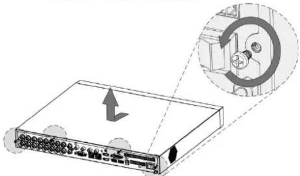
2.2.1 DH-XVR42xxAN-I/DH-XVR42xxAN-I(V2.0)/DH-XVR52xxA-I2/DH-XVR52xxA-I3/DH-XVR52xxA-4KL-I2/DH-XVR52xxA-4KL-I3/DH-XVR52xxAN-I2/DH-XVR52xxAN-I3/DH-XVR52xxAN-4KL-I2/DH-XVR52xxAN-4KL-I3/DH-XVR72xxA-4K-I2/DH-XVR72xxA-4K-I3/DH-XVR72xxA-4KL-I/DH-XVR72xxAN-4K-I2/DH-XVR72xxAN-4K-I3/DH-XVR82xxA-4K-I/DH-XVR82xxA-4KL-I
Step 1 Remove the screws to take off the cover.
Figure 2-1 Remove screws
natural_image
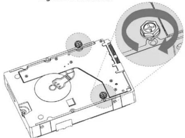
Diagram of a server rack with an inset showing a mechanical component (no text or symbols present)Step 2 Put two screws on the HDD and twist one turn.
Figure 2-2 Put screws
natural_image
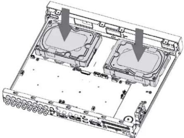
Technical line drawing of a hard disk drive with internal components and a circular inset showing a bolt mechanism (no text or symbols)Step 3 Align the two screws with the holes on the device.
Figure 2-3 Align screws
natural_image
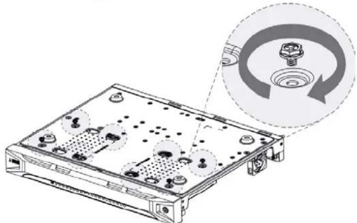
Technical diagram of an internal server rack with two ports and mounting hardware (no text or labels)Step 4 Turn the device and put in the other two screws, and then fasten all screws to fix the HDD to the device.
Figure 2-4 Fasten screws
natural_image
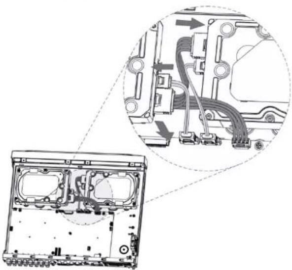
Diagram of a computer drive chassis with an inset showing a circular component being inserted (no text or symbols present)Step 5 Use power cable and data cable to connect the device and HDD.
Figure 2-5 Connect cables
natural_image
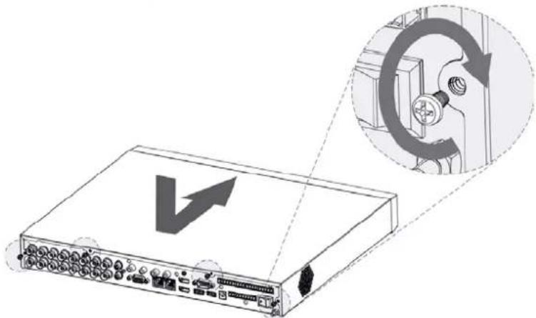
Technical diagram of a computer motherboard showing internal components and wiring (no text or labels)Step 6 Put back the cover and fasten the screws.
Figure 2-6 Put back cover
natural_image
Illustration of a network device with an arrow indicating direction, showing internal components and a close-up of the switch mechanism (no text or symbols present)2.2.2 DH-XVR58xxS-I2/DH-XVR58xxS-4KL-I2/DH-XVR58xxS-4KL-I2-LP/DH-XVR58xxS-I3/DH-XVR58xxS-4KL-I3/DH-XVR58xxS-4KL-I3-LP/DH-XVR78xxS-4K-I2/DH-XVR78xxS-4K-I3/DH-XVR78xxS-4KL-X-LP-V2/DH-XVR88xxS-4KL-I
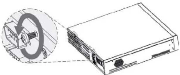
Step 1 Remove the screws from the chassis.
Figure 2-7 Remove screws
natural_image
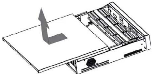
Diagram of a server rack connected to a device via a circular switch mechanism (no text or symbols present)Step 2 Take off the cover of the chassis.
Figure 2-8 Take off cover
natural_image
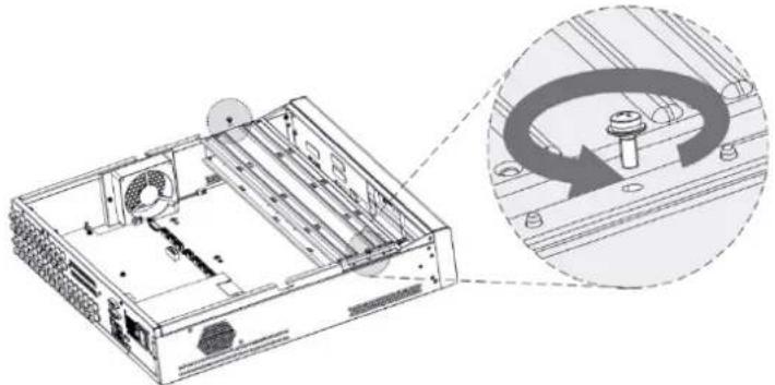
Isometric line drawing of a computer chassis with an upward arrow indicating motion (no text or symbols)Step 3 Remove the screws from the drive bracket to take it off.
Figure 2-9 Take off drive bracket
natural_image
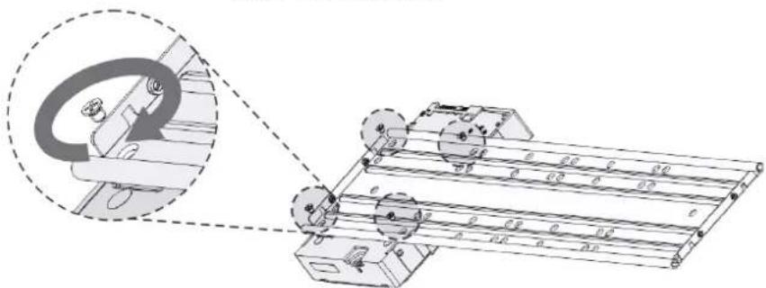
Technical line drawing of a computer drive chassis with an inset showing internal components (no text or symbols)Step 4 Align the four screw holes on the disk to those on the drive bracket and fix the disk on the bracket.
Figure 2-10 Fix disk
natural_image
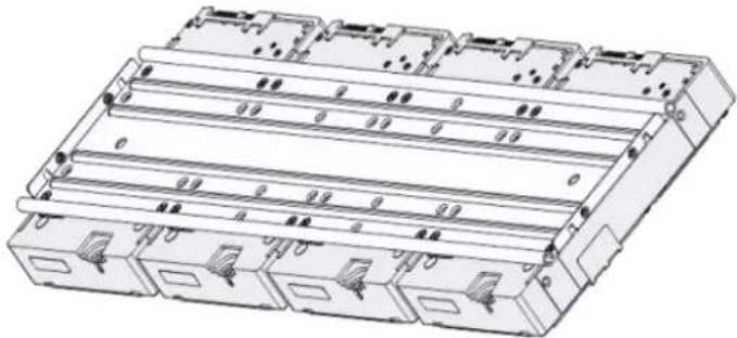
Mechanical assembly diagram showing a rotating component and a linear conveyor system (no text or symbols)Step 5 Fix other disks on the bracket as needed.
Figure 2-11 Fix other disks
natural_image
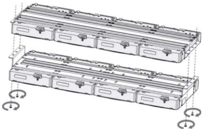
Technical line drawing of a multi-tiered electronic device casing with mounting holes and internal compartments (no text or symbols)Step 6 Fix the two drive brackets.

This is only needed on models with 8 bays.
Figure 2-12 Fix drive brackets
natural_image
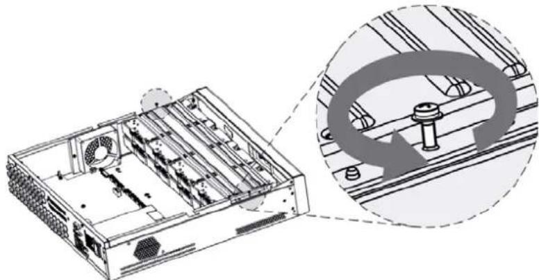
Technical line drawing of two stacked electronic device modules with mounting holes and ventilation slots (no text or symbols)Step 7 Put the drive brackets back and fix them in the DVR.
Figure 2-13 Put back drive bracket
natural_image
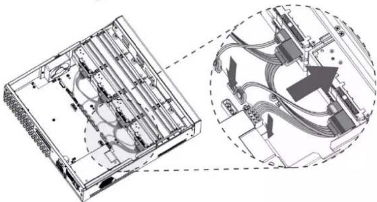
Technical line drawing of a server rack with internal components and a magnified inset showing a circular component detail (no text or symbols)Step 8 Connect the disks and the DVR with power cable and data cable.

The following figure shows the connection of 4-bay model for example.
Figure 2-14 Connect cables
natural_image
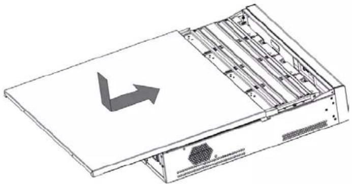
Technical diagram of an electronic device showing internal components and wiring, with no visible text or symbols.Step 9 Put the cover back and fasten the screws.
Figure 2-15 Put back cover
natural_image
Technical line drawing of a server rack with an open lid and internal compartments (no text or symbols)2.2.3 DH-XVR54xxL-I2/DH-XVR54xxL-4KL-I2/DH-XVR54xxL-I3/DH-XVR54xxL-4KL-I3/DH-XVR74xxL-4K-I2/DH-XVR74xxL-4K-I3
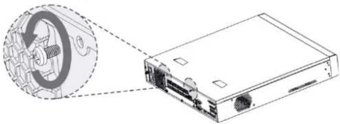
Step 1 Remove the fixing screws from the rear panel.
Figure 2-16 Remove screws
natural_image
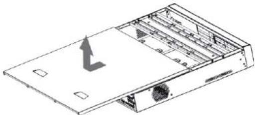
Diagram of a computer drive showing internal components and external ports (no text or labels)Step 2 Remove the cover along the direction shown in the following arrow.
Figure 2-17 Remove cover
natural_image
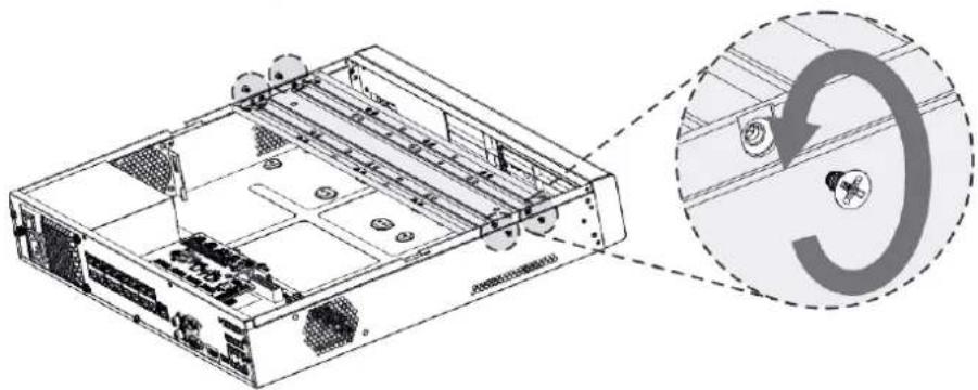
Technical line drawing of a computer chassis with an arrow indicating a component (no text or symbols present)Step 3 Remove the screws on the sides of HDD bracket to take out the bracket. For the way to remove the bracket, see the following figure.
Figure 2-18 Remove bracket
natural_image
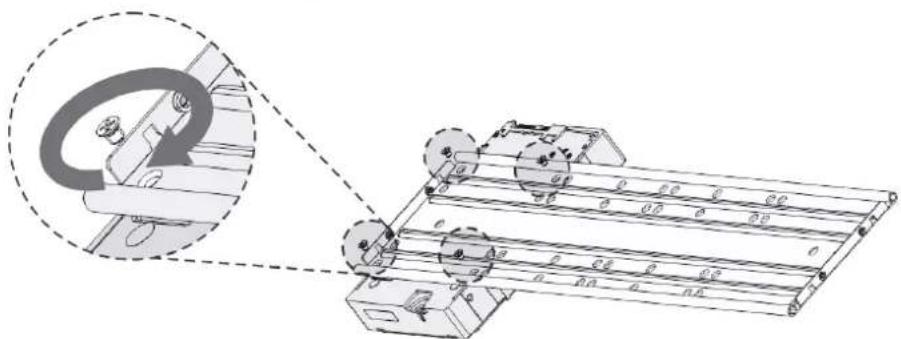
Technical line drawing of a server rack with internal components and a circular diagram showing a rotating mechanism (no text or symbols)Step 4 Match the four screw holes on the HDD with the four holes on the bracket and then fasten the screws. The HDD is fixed to the bracket.
Figure 2-19 Fix HDD
natural_image
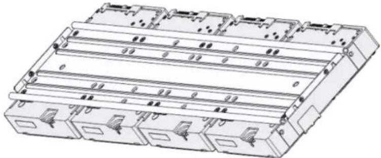
Technical line drawing of a mechanical assembly with a magnified inset showing a circular component (no text or symbols)Step 5 Install the other HDDs.
Figure 2-20 Install other HDDs
natural_image
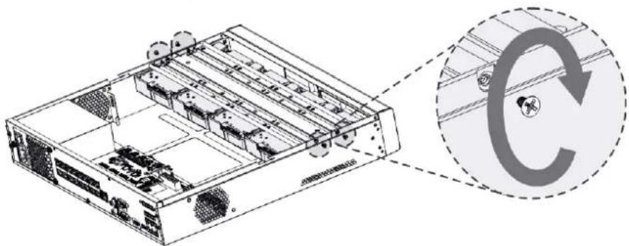
Technical line drawing of a multi-layered industrial or electronic component assembly (no text or symbols visible)Step 6 Place the bracket to the device and then fasten the screws on the sides of the bracket.
Figure 2-21 Fasten screws
natural_image
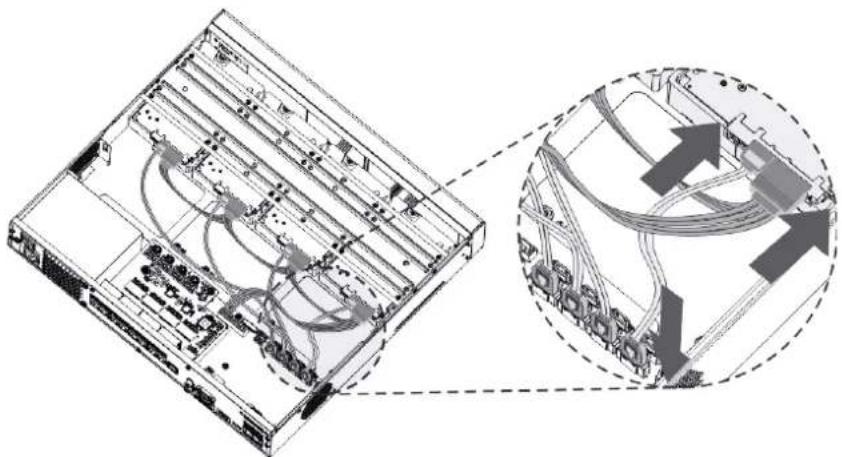
Technical line drawing of a server rack with internal components and an inset circular diagram showing refresh or sync operation (no text or symbols)Step 7 Connect the HDD data cable and power cable to the device.
Figure 2-22 Connect cables
natural_image
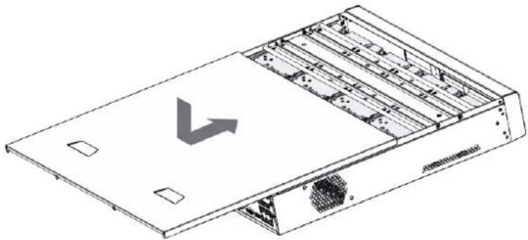
Technical diagram of a server rack with internal cable routing and external wiring, shown in two views (no text or labels)Step 8 Put back the cover and fasten the screws on the rear panel to complete the installation.
Figure 2-23 Put back cover
natural_image
Technical line drawing of a server rack with ventilation ducts and mounting holes (no text or symbols)2.2.4 DH-XVR1Bxx-I/DH-XVR1BxxH-I/DH-XVR41xxC-I/DH-XVR41xxHS-I/DH-XVR51xxH-I/DH-XVR51xxH-I2/DH-XVR51xxH-I3/DH-XVR51xxH-4KL-I2/DH-XVR51xxH-4KL-I3/DH-XVR51xxHE-I2/DH-XVR51xxHE-I3/DH-XVR51xxHE-4KL-I2/DH-XVR51xxHE-4KL-I3/DH-XVR51xxHS-I2/DH-XVR51xxHS-I3/DH-XVR51xxHS-4KL-I2/DH-XVR51xxHS-4KL-I3/DH-XVR71xxH-4K-I2/DH-XVR71xxH-4K-I3/DH-XVR71xxHE-4KL-I/DH-XVR71xxHE-4K-I2/DH-XVR71xxHE-4K-I3
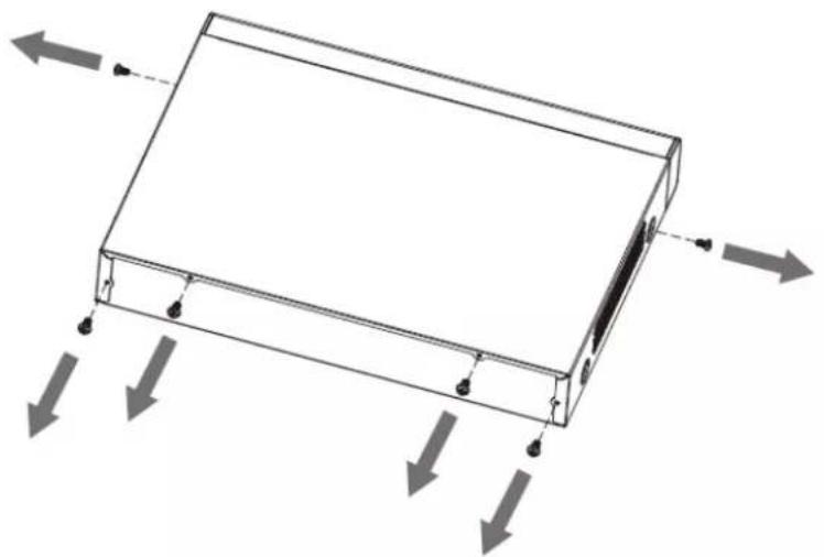
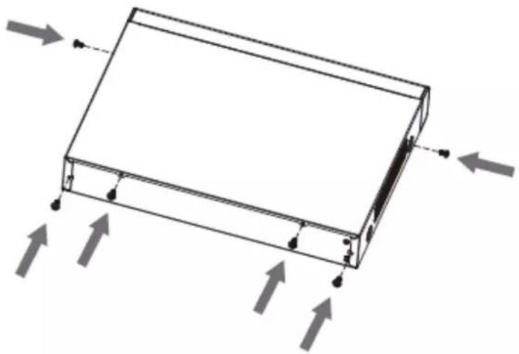
Step 1 Remove the screws on the cover.
Figure 2-24 Remove screws
natural_image
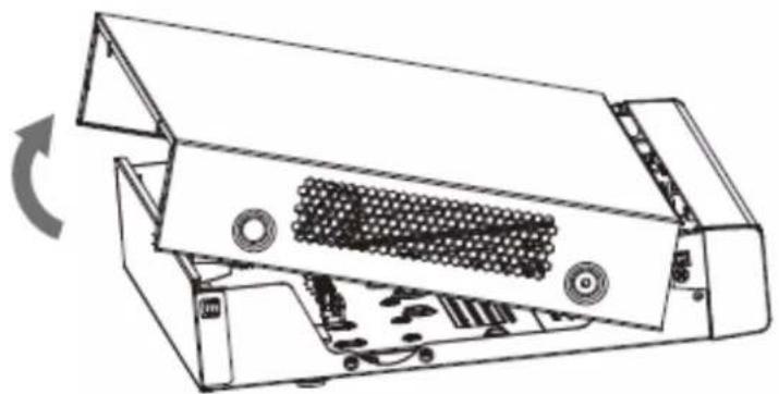
3D diagram of a rectangular electronic device with directional arrows indicating force or movement (no text or symbols)Step 2 Remove the cover.
Figure 2-25 Remove cover
natural_image
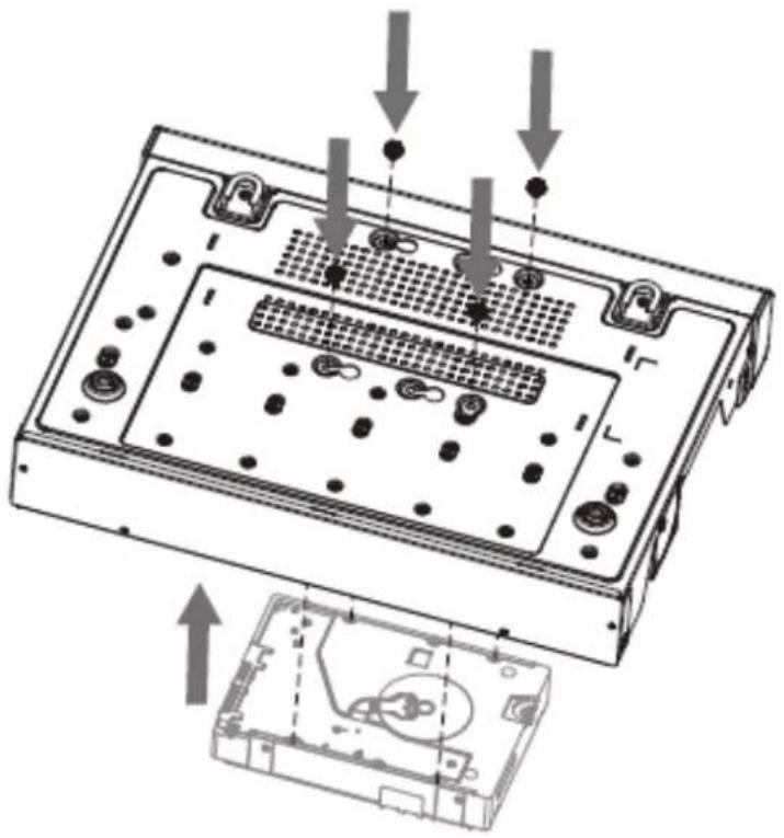
Technical line drawing of an open computer case with internal components and a circular arrow indicating rotation (no text or symbols)Step 3 Align the screws of the HDD with the holes on the back of the device and fasten them.
Figure 2-26 Fasten screws
natural_image
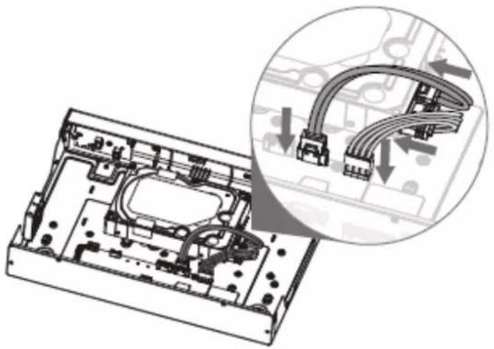
Diagram of an electronic device showing internal components and mounting points (no text or symbols)Step 4 Connect the HDD cable and the power cable to the mainboard.
Figure 2-27 Connect cables
natural_image
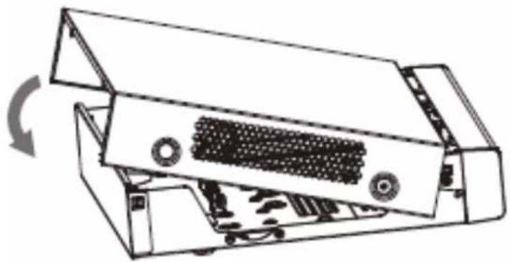
Technical diagram of an electronic device showing internal components and cable routing (no text or labels)Step 5 Put back the cover.
Figure 2-28 Put back cover
natural_image
Diagram of a computer tower case with internal components and a circular arrow indicating rotation (no text or symbols)Step 6 Fasten the screws.
Figure 2-29 Fasten screws
natural_image
Diagram of a rectangular electronic component with directional arrows indicating force or movement (no text or symbols)2.2.5 DH-XVR51xxC-I3/DH-XVR51xxC-4KL-I3
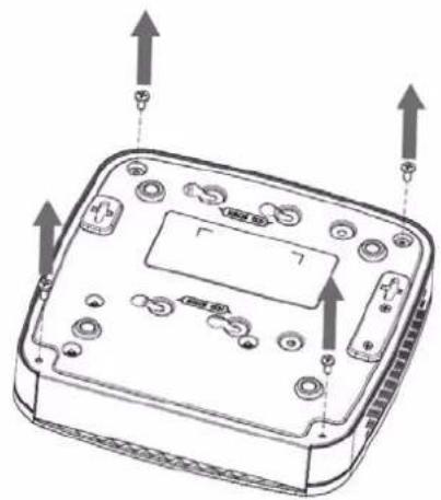
Step 1 Remove the screws.
Figure 2-30 Remove screws
natural_image
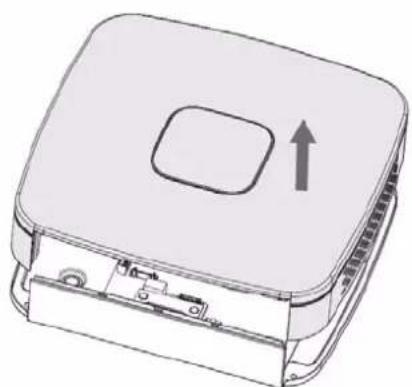
Diagram of a device casing with mounting holes and directional arrows indicating top and bottom views (no text or symbols present)Step 2 Take off the cover.
Figure 2-31 Take off cover
natural_image
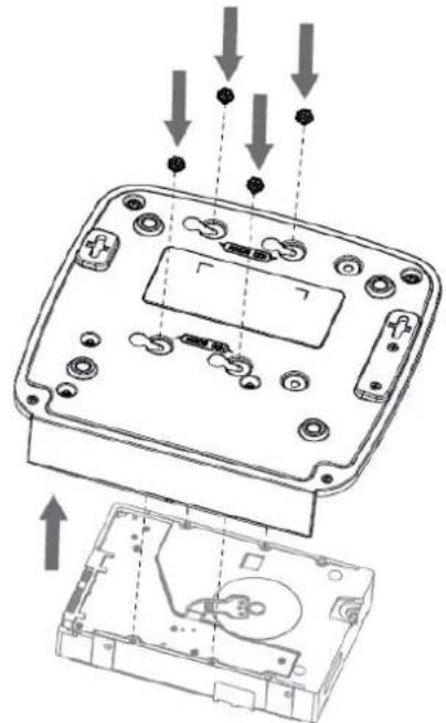
Illustration of a square electronic device with a square button and an upward arrow, no text or symbols present.Step 3 Align the screws with the holes on the DVR and fasten them.
Figure 2-32 Install HDD
natural_image
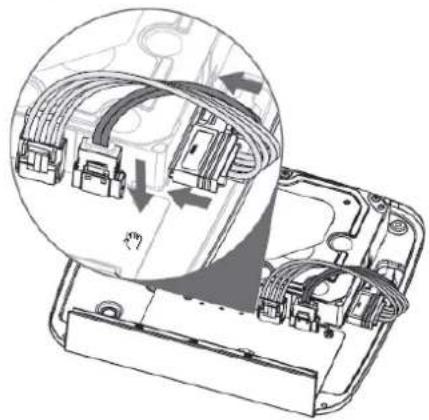
Technical diagram of an electronic device showing internal components and directional arrows (no text or symbols)Step 4 Use the HDD cable and power cable to connect HDD and mainboard.
Figure 2-33 Connect cables
natural_image
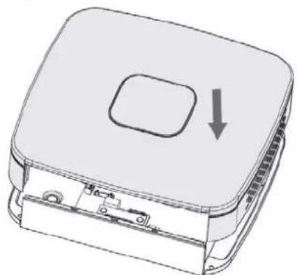
Technical diagram of an electronic device showing internal components and wiring (no text or symbols)Step 5 Put back the cover.
Figure 2-34 Put back cover
natural_image
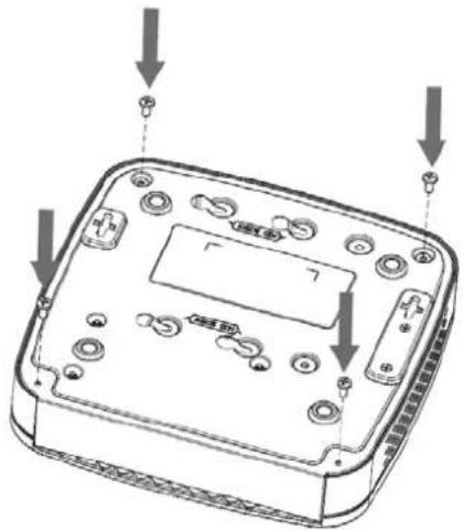
Illustration of a rectangular electronic device with a square button and a downward arrow indicating a component (no text or symbols present)Step 6 Fasten the screws.
Figure 2-35 Fasten screws
natural_image
Diagram of a device casing with labeled ports and arrows indicating assembly or connection (no text or symbols present)3 The Grand Tour
This chapter introduces various components of the Device, remote control and mouse operations.
3.1 Front Panel
3.1.1 DH-XVR51xxH-I
Figure 3-1 Front panel
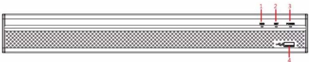
Table 3-1 Front panel description
| No. | Port Name | Function |
| 1 | HDD | Glows blue when HDD status is abnormal. |
| 2 | NET | Glows blue when network status is abnormal. |
| 3 | POWER | Glows blue when the power is connected properly. |
| 4 USB port | Connects to peripheral devices such as USB storage device, keyboard, and mouse. | |
3.1.2 DH-XVR71xxH-4K-I2/DH-XVR71xxH-4K-I3/DH-XVR71xxHE-4K-I2/DH-XVR71xxHE-4K-I3/DH-XVR71xxHE-4KL-I
Figure 3-2 Front panel
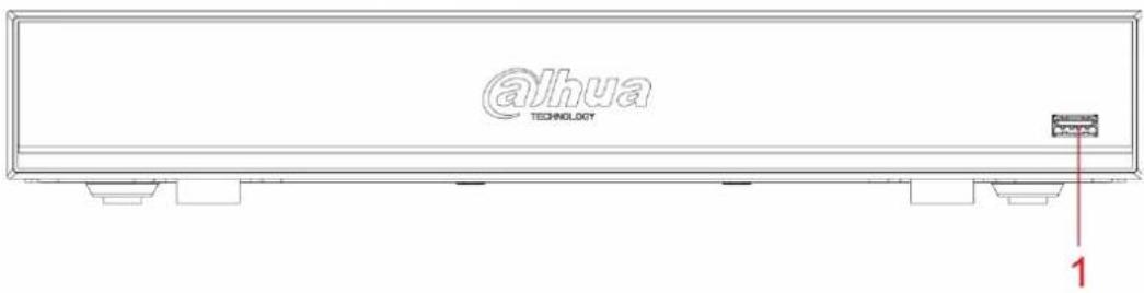
Table 3-2 Front panel description
| No. | Port Name | Function |
| 1 USB port | Connects to peripheral devices such as USB storage device, keyboard and mouse. | |
3.1.3 DH-XVR72xxA-4KL-I/DH-XVR72xxAN-4K-I2/DH-XVR72xxA-4K-I2/DH-XVR72xxAN-4K-I3/DH-XVR72xxA-4K-I3
Figure 3-3 Front panel
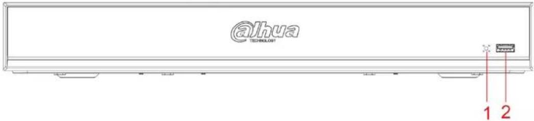
Table 3-3 Front panel description
| No. | Port Name | Function |
| 1 | IR receiver | Receives infrared signal from remote control. |
| 2 USB port | Connects to the external devices such as keyboard, mouse, and USB storage device. | |
3.1.4 DH-XVR82xxA-4K-I/DH-XVR82xxA-4KL-I
Figure 3-4 Front panel
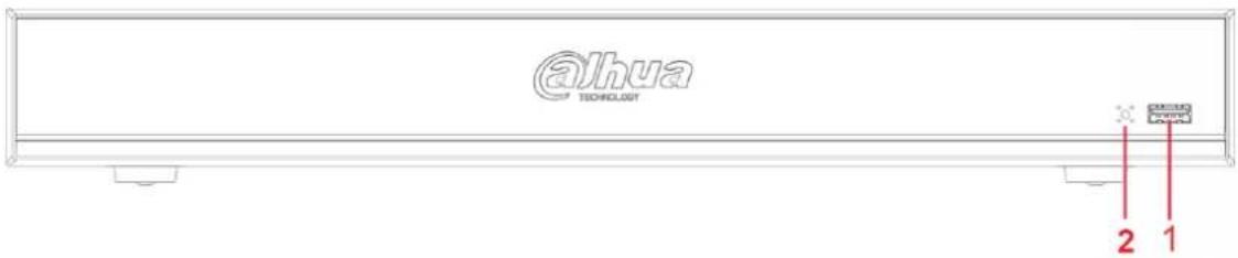
Table 3-4 Front panel description
| No. | Indicator/Port | Function |
| 1 USB port | Connects to peripheral devices such as USB storage device, keyboard, and mouse. | |
| 2 | IR receiver | Receives infrared signal from remote control. |
3.1.5 DH-XVR41xxC-I/DH-XVR41xxHS-I/DH-XVR42xxAN-I/DH-XVR42xxAN-I(V2.0)/DH-XVR51xxH-I2/DH-XVR51xxH-I3/DH-XVR51xxH-4KL-I2/DH-XVR51xxH-4KL-I3/DH-XVR51xxHE-I2/DH-XVR51xxHE-I3/DH-XVR51xxHE-4KL-I2/DH-XVR51xxHE-4KL-I3/DH-XVR51xxHS-I2/DH-XVR51xxHS-I3/DH-XVR51xxHS-4KL-I2/DH-XVR51xxHS-4KL-I3/DH-XVR52xxA-I2/DH-XVR52xxA-I3/DH-XVR52xxA-4KL-I2/DH-XVR52xxA-4KL-I3/DH-XVR52xxAN-I2/DH-XVR52xxAN-I3/DH-XVR52xxAN-4KL-I2/DH-XVR52xxAN-4KL-I3
Figure 3-5 Front panel

Table 3-5 Front panel description
| No. | Port Name | Function |
| 1 | HDD | Glows when HDD status is abnormal. |
| 2 | NET | Glows when network status is abnormal. |
| 3 | POWER | Glows when the power is connected properly. |
| 4 USB port | Connects to peripheral devices such as USB storage device, keyboard, and mouse. | |
3.1.6 DH-XVR78xxS-4K-I2/DH-XVR78xxS-4K-I3/DH-XVR78xxS-4KL-X-LP-V2/DH-XVR88xxS-4KL-I
Figure 3-6 Front panel
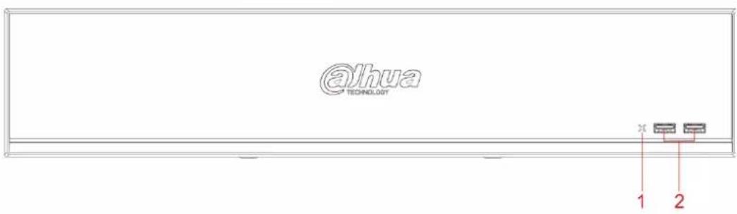
Table 3-6 Front panel description
| No. | Port Name | Function |
| 1 | IR receiver | Receives infrared signal from remote control. |
| 2 USB port | Connects to peripheral devices such as USB storage device, keyboard, and mouse. | |
3.1.7 DH-XVR74xxL-4K-I2/DH-XVR74xxL-4K-I3
Figure 3-7 Front panel
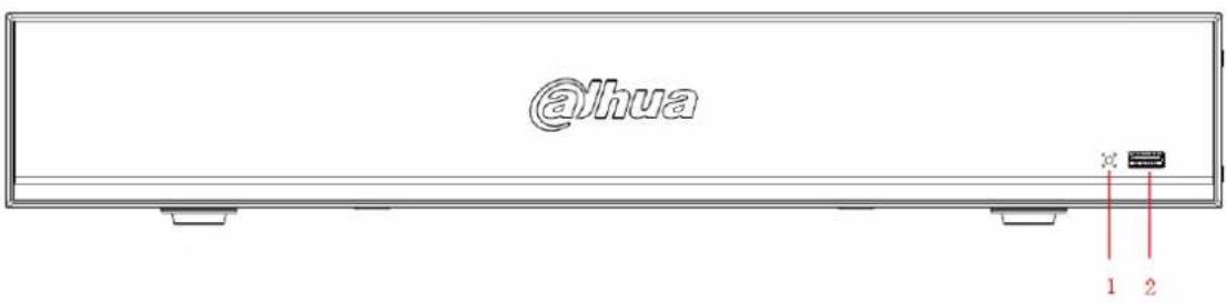
Table 3-7 Front panel description
| No. | Port Name | Function |
| 1 | IR receiver | Receives infrared signal from remote control. |
| 2 USB port | Connects to peripheral devices such as USB storage device, keyboard, and mouse. | |
3.1.8 DH-XVR54xxL-I2/DH-XVR54xxL-4KL-I2/DH-XVR54xxL-I3/DH-XVR54xxL-4KL-I3
Figure 3-8 Front panel
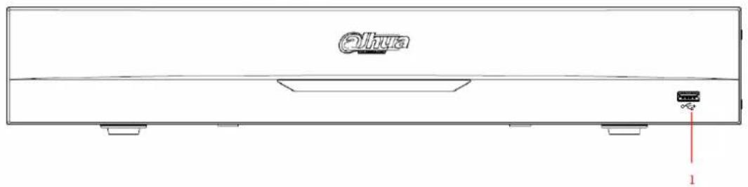
Table 3-8 Front panel description
| No. | Port Name | Function |
| 1 USB port | Connects to peripheral devices such as USB storage device, keyboard, and mouse. | |
3.1.9 DH-XVR58xxS-I2/DH-XVR58xxS-I3/DH-XVR58xxS-4KL-I2/DH-XVR58xxS-4KL-I3/DH-XVR58xxS-4KL-I2-LP/DH-XVR58xxS-4KL-I3-LP
Figure 3-9 Front panel
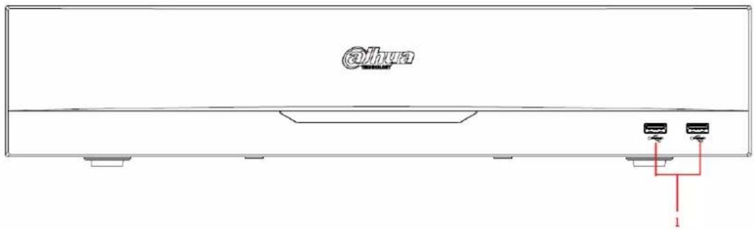
Table 3-9 Front panel description
| No. | Port Name | Function |
| 1 USB ports | Connect to peripheral devices such as USB storage device, keyboard, and mouse. | |
3.1.10 DH-XVR1Bxx-I/DH-XVR1BxxH-I
Figure 3-10 Front panel
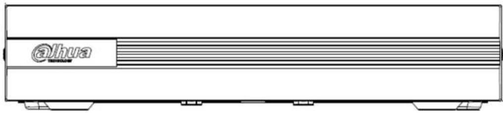
Figure 3-11 Front panel

natural_image
Simple geometric diagram with a square and rounded rectangle inside a rounded square (no text or symbols)Table 3-10 Front panel description
| Icon | Name | Function |
| HDD status indicator | The indicator is off when the HDD is running normally.The indicator glows blue when the HDD is in malfunction. | |
| Power status indicator | The indicator is off when the power is connected abnormally.The indicator glows blue when the power is connected normally. | |
| Network status indicator | The indicator is off when the network connection is correct.The indicator glows blue when the network connection is abnormal. |
3.2 Rear Panel
3.2.1 DH-XVR51xxH-I/DH-XVR51xxH-I2/DH-XVR51xxH-I3/DH-XVR51xxH-4KL-I2/DH-XVR51xxH-4KL-I3/DH-XVR51xxHE-I2/DH-XVR51xxHE-I3/DH-XVR51xxHE-4KL-I2/DH-XVR51xxHE-4KL-I3/DH-XVR71xxH-4K-I2/DH-XVR71xxH-4K-I3/DH-XVR71xxHE-4K-I2/DH-XVR71xxHE-4K-I3/DH-XVR71xxHE-4KL-I
Figure 3-12 Rear panel
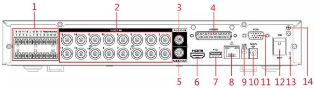
Table 3-11 Rear panel description
| No. | Port Name | Function |
| 1 | Alarm input port 1–16 | Four groups of alarm input ports (Group 1: port 1 to port 4; Group 2: port 5 to port 8; Group 3: port 9 to port 12; Group 4: port 13 to port 16). These ports receive the signal from the external alarm source.There are two types: NO (Normally Open) and NC (Normally Closed).When your alarm input device is using external power, make sure the alarm input device and the Device have the same ground. |
| Alarm output port 1–3 (NO1–NO3; C1–C3) | Three groups of alarm output ports (Group 1: port NO1–C1, Group 2: port NO2–C2, Group 3: port NO3–C3). These ports output alarm signal to the alarm device. Make sure power supply to the external alarm device.NO: Normally open alarm output port.C: Alarm output public end. | |
| 1= | Ground. | |
| 2 | Video input port | Connects to analog camera to input video signal. |
| 3 Audio input port | Receives audio signal output from the devices such as microphone.It corresponds to video input port 1. | |
| 4 DB25 | port | Connects to the audio splitter taken from the package to convert to audio input port which receives the audio signal from devices such as microphone. It corresponds to video input ports 2–16. |
| 5 | Audio output port | Outputs audio signal to the devices such as the sound box. |
| 6 HDMI | port | High definition audio and video signal output port.The port outputs the uncompressed high definition video and multi-channel audio data to the connected display with HDMI port. |
| 7 USB | port | Connects to external devices such as USB storage device, keyboard and mouse. |
| 8 | Network port | Connects to Ethernet port. |
| 9 | RS-485 communication port | Connects to the control devices such as speed dome PTZ. RS-485_A port is connected by the cable A and RS-485_B is connected to the cable B. |
| 10 | Power input port | Inputs 12 VDC power. |
| 11 | VGA port | Outputs analog video data to the connected display with VGA port. |
| 12 | Power button | Turns on/off the DVR. |
| 13 | Power cable fastener | Use a cable tie to secure the power cable on the DVR to prevent loss. |
| 14 | Ground terminal. | |
3.2.2 DH-XVR41xxC-I/DH-XVR41xxHS-I/DH-XVR51xxHS-I2/DH-XVR51xxHS-I3/DH-XVR51xxHS-4KL-I2/DH-XVR51xxHS-4KL-I3
Figure 3-13 Rear panel
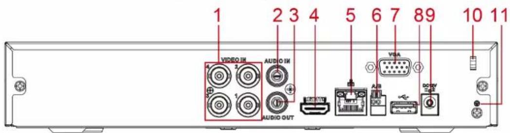
Table 3-12 Rear panel description
| No. | Port Name | Function |
| 1 | Video input port | Connects to analog camera to input video signal. |
| 2 | Audio input port | Receives audio signal output from the devices such as microphone. |
| 3 | Audio output port | Outputs audio signal to the devices such as the sound box. |
| 4 HDMI | port | High definition audio and video signal output port.The port outputs the uncompressed high definition video and multi-channel audio data to the connected display with HDMI port. |
| 5 | Network port | Connects to Ethernet port. |
| 6 | RS-485 communication port | Connects to the control devices such as speed dome PTZ. RS-485_A port is connected by the cable A and RS-485_B is connected to the cable B. |
| 7 | VGA port | Outputs analog video data to the connected display with VGA port. |
| 8 USB port | Connects to external devices such as USB storage device, keyboard and mouse. | |
| 9 | Power input port | Inputs 12 VDC power. |
| 10 | Power cable fastener | Use clamp to secure the power cable on the DVR in case there is any loss. |
| 11 | Ground terminal. | |
3.2.3 DH-XVR52xxA-I2/DH-XVR52xxA-I3/DH-XVR52xxA-4KL-I2/DH-XVR52xxA-4KL-I3/DHXVR42xxAN-I/DH-XVR42xxAN-I(V2.0)/DH-XVR52xxAN-I2/DH-XVR52xxAN-I3/DH-XVR52xxAN-4KL-I2/DH-XVR52xxAN-4KL-I3/DH-XVR72xxA-4K-I2/DH-XVR72xxA-4K-I3/DH-XVR72xxA-4KL-I/DH-XVR72xxAN-4K-I2/DH-XVR72xxAN-4K-I3
Figure 3-14 Rear panel
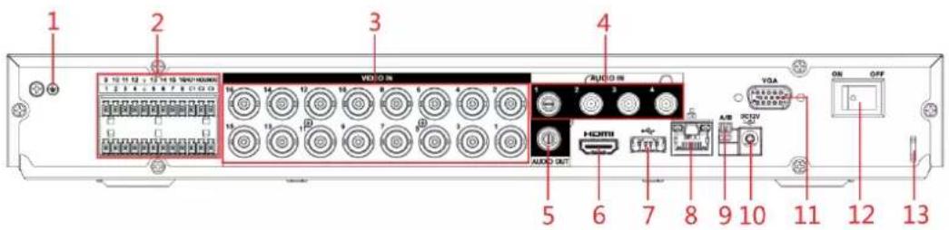
Table 3-13 Rear panel description
| No. | Port Name | Function |
| 1 | Ground terminal. | |
| 2 | Alarm input port 1-16 | Four groups of alarm input ports (Group 1: port 1 to port 4; Group 2: port 5 to port 8; Group 3: port 9 to port 12; Group 4: port 13 to port 16). These ports receive the signal from the external alarm source.There are two types: NO (Normally Open) and NC (Normally Closed).When your alarm input device is using external power, make sure the alarm input device and the DVR connect to the same ground. |
| Alarm output port 1-3 (NO1-NO3; C1-C3) | Three groups of alarm output ports. (Group 1: port NO1-C1, Group 2: port NO2-C2, Group 3: port NO3-C3). These ports output alarm signal to the alarm device. Make sure power supply to the external alarm device.NO: Normally open alarm output port.C: Alarm output public end. | |
| 12 | Ground. | |
| 3 | Video input port | Connects to analog camera to input video signal. |
| 4 | Audio input port | Receives audio signal output from the devices such as microphone. |
| 5 | Audio output port | Outputs audio signal to the devices such as the sound box. |
| 6 HDMI | port | High definition audio and video signal output port.The port outputs the uncompressed high definition video and multi-channel audio data to the connected display with HDMI port. |
| 7 USB port | Connects to the external devices such as keyboard, mouse, and USB storage device. | |
| 8 | Network port | Connects to Ethernet port. |
| 9 | RS-485 communication port | Connects to the control devices such as speed dome PTZ. RS-485_A port is connected by the cable A and RS-485_B is connected to the cable B. |
| 10 | Power input port | Inputs 12 VDC power. |
| 11 | VGA port | Outputs analog video data to the connected display with VGA port. |
| 12 | Power button | Turns on/off the DVR. |
| 13 | Power cable fastener | Use clamp to secure the power cable on the DVR in case there is any loss. |
3.2.4 DH-XVR82xxA-4K-I/DH-XVR82xxA-4KL-I
Figure 3-15 Rear panel
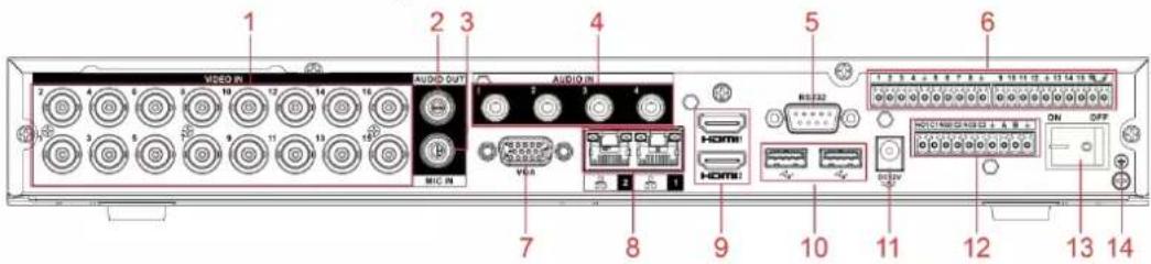
Table 3-14 Rear panel description
| No. | Port Name | Function |
| 1 | Video input port | Connects to analog camera to input video signal. |
| 2 | Audio output port | Outputs audio signal to the devices such as the sound box. |
| 3 | MIC IN | Two-way talk input port which receives analog audio signal output from the devices such as microphone and pickup. |
| 4 | Audio input port | Receives audio signal output from the devices such as microphone. |
| 5 | RS-232 debug COM | The port is used for general COM debug to configure IP address or transfer transparent COM data. |
| 6 | Alarm input port1–16 | 4 groups of alarm input ports (Group 1: port 1 to port 4; Group 2: port 5 to port 8; Group 3: port 9 to port 12; Group 4: port 13 to port 16). These ports receive the signal from the external alarm source.There are two types: NO (normal open) and NC (normal close).When your alarm input device is using external power, make sure the input device and the DVR connect to the same ground. |
| ⊕ | Ground terminal. | |
| 7 | VGA port | Outputs analog video data to the connected display with VGA port. |
| 8 | Network port | Connects to Ethernet port. |
| 9 HDMI port | High definition audio and video signal output port.The port outputs the uncompressed high definition video and multi-channel audio data to the connected display with HDMI port. | |
| 10 USB port | Connects to the external devices such as keyboard, mouse, and USB storage device. | |
| 11 | Power input port | Inputs power. |
| 12 | Alarm output port 1–5 (NO1–NO5; C1–C5; NC5) | 5 groups of alarm output ports (Group 1: port NO1–C1, Group 2: port NO2–C2, Group 3: port NO3–C3, Group 4: port NO4–C4, Group 5: port NO5, C5, NC5). These ports output alarm signal to the alarm device. Make sure power supply to the external alarm device.NO: Normal open alarm output port.C: Alarm output public end.NC: Normal close alarm output port. |
| 13 | Power button | Turns on/off the DVR. |
| 14 | ± | Ground. |
3.2.5 DH-XVR58xxS-I2/DH-XVR58xxS-4KL-I2/DH-XVR58xxS-I3/DH-XVR58xxS-4KL-I3/DH-XVR78xxS-4K-I2/DH-XVR78xxS-4K-I3/DH-XVR88xxS-4KL-I
Figure 3-16 Rear panel
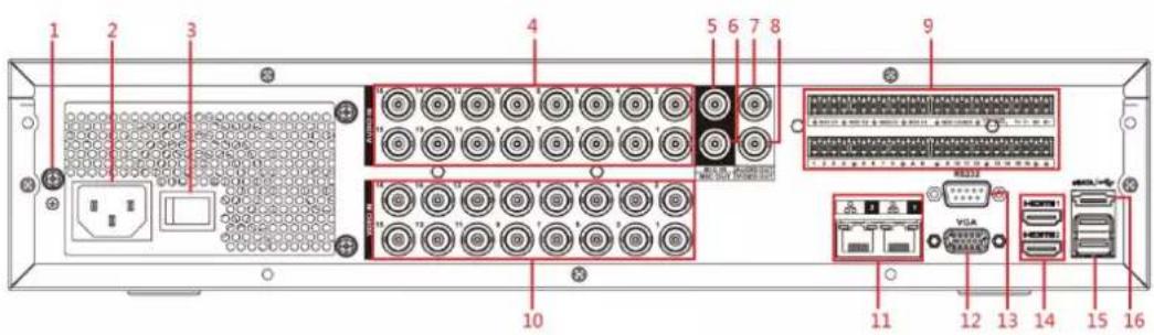
Table 3-15 Rear panel description
| No. | Port Name | Function |
| 1 GND | Ground. | |
| 2 | Power input port | Inputs power. |
| 3 | Power button | Turns on/off the Device. |
| 4 | Audio input port | Receives the analog audio signal output from the devices such as microphone. |
| 5 | Audio input port (MIC IN) | Two-way talk input port which receives the analog audio signal output from the devices such as microphone, pickup. |
| 6 | Audio output port (MIC OUT) | Two-way talk output port which outputs the analog audio signal to the devices such as the sound box. |
| 7 | Audio output port | Outputs the analog audio signal to the devices such as the sound box. |
| 8 | Video output port | Connect to video output devices such as TV. |
| 9 | Alarm input port 1-16 | Four groups of alarm output ports (Group 1: port 1 to port 4; Group 2: port 5 to port 8; Group 3: port 9 to port 12; Group 4: port 13 to port 16). These ports receive the signal from the external alarm source. There are two types; NO (Normally Open) and NC (Normally Closed).When your alarm input device is using external power, make sure the device and the NVR have the same ground. |
| Alarm output port 1-5 (NO1-NO5; C1-C5; NC5) | Five groups of alarm output ports. (Group 1: port NO1-C1, Group 2: port NO2-C2, Group 3: port NO3-C3, Group 4: port NO4-C4, Group 5: port NO5, C5, NC5). These ports output alarm signal to the alarm device. Make sure power supply to the external alarm device.NO: Normally open alarm output port.C: Alarm output public end.NC: Normally closed alarm output port. | |
| RS-485 communication port | You can connect to the control devices such as speed dome PTZ.RS-485_A port is connected by the cable A and RS-485_B is connected to the cable B. | |
| Four-wire full-duplex RS-485 port (T+, T-, R+, R-) | Four-wire full-duplex 485 port. T+ and T- is the output wire; R+ and R- is the input wire. | |
| Control power output (CTRL 12V) | Controls 12 VDC power output. It is to control the on-off alarm relay output. | |
| 12V power output port | Provides power to external devices such as camera and alarm device. Note the supplying power shall be below 1A. | |
| ± | Ground. | |
| 10 | Video input port | Connect to analog camera to input video signal. |
| 11 | Network port | Connects to Ethernet port. |
| 12 VGA | video output | Outputs analog video signal. It can connect to the monitor to view analog video. |
| 13 | RS-232 debug COM | It is for general COM debug to configure IP address or transfer transparent COM data. |
| 14 HDMI port | High definition audio and video signal output port. It outputs the same video source as VGA. It supports 4K resolution output and supports mouse operation and control.Note when the HDMI output resolution is 4K, the VGA output stops. | |
| 15 USB port | Connects to the external devices such as keyboard, mouse, and USB storage device. | |
| 16 | eSATA port | External SATA port which connects to the device with SATA port.Perform the jumper configuration when connecting HDD. |
3.2.6 DH-XVR58xxS-4KL-I2-LP/DH-XVR58xxS-4KL-I3-LP/DH-
XVR78xxS-4KL-X-LP-V2
Figure 3-17 Rear panel
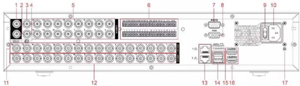
Table 3-16 Rear panel description
| No. | Port Name | Function |
| 1 Audio output port | Outputs the analog audio signal to the devices such as the sound box. | |
| 2 | Video output port | Connect to video output devices such as TV. |
| 3 | Audio input port (MIC IN) | Two-way talk input port which receives the analog audio signal output from the devices such as microphone, pickup. |
| 4 | Audio output port (MIC OUT) | Two-way talk output port which outputs the analog audio signal to the devices such as the sound box. |
| 5 | Audio input port | Receives the analog audio signal output from the devices such as microphone. |
| 6 | Alarm input port 1-16 | Four groups of alarm output ports (Group 1: port 1 to port 4; Group 2: port 5 to port 8; Group 3: port 9 to port 12; Group 4: port 13 to port 16). These ports receive the signal from the external alarm source. There are two types; NO (Normally Open) and NC (Normally Closed).When your alarm input device is using external power, make sure that the device and the NVR have the same ground. |
| Alarm output port 1-5 (NO1-NO5; C1-C5; NC5) | Five groups of alarm output ports. (Group 1: port NO1-C1,Group 2: port NO2-C2,Group 3: port NO3-C3, Group 4: port NO4-C4, Group 5: port NO5, C5, NC5). These ports output alarm signal to the alarm device. Make sure that power supply to the external alarm device.NO: Normally open alarm output port.C: Alarm output public end.NC: Normally closed alarm output port. | |
| RS-485 communication port | You can connect to the control devices such as speed dome PTZ.RS-485_A port is connected by the cable A and RS-485_B is connected to the cable B. | |
| Four-wire full-duplex RS-485 port (T+, T-, R+, R-) | Four-wire full-duplex 485 port. T+ and T- is the output wire; R+ and R- is the input wire. | |
| Control power output (CTRL 12V) | Controls the 6^th channel power output for alarm.Turns off power output when there is alarm output.Turns on power output when the alarm is cleared. | |
| 12V power output port | Provides power to external devices such as camera and alarm device. Note the supplying power shall be below 1A. | |
| G Ground. | ||
| 7 | RS-232 debug COM | It is for general COM debug to configure IP address or transfer transparent COM data. |
| 8 VGA video output | Outputs analog video signal. It can connect to the monitor to view analog video. | |
| 9 | Power button | Turns on/off the Device. |
| 10 | Power input port | Inputs power. |
| 11 | Loop out | Outputs the video signal of the corresponding video input port. |
| 12 | Video input port | Connect to analog camera to input video signal. |
| 13 | Network port | Connects to Ethernet port. |
| 14 USB port | Connects to the external devices such as keyboard, mouse, and USB storage device. | |
| 15 | eSATA port | External SATA port which connects to the device with SATA port. Perform the jumper configuration when connecting HDD. |
| 16 HDMI port | High definition audio and video signal output port. It outputs the same video source as VGA. It supports 4K resolution output and supports mouse operation and control.Note when the HDMI output resolution is 4K, the VGA output stops. | |
| 17 | GND | Ground. |
3.2.7 DH-XVR54xxL-I2/DH-XVR54xxL-4KL-I2/DH-XVR54xxL-I3/DH-
XVR54xxL-4KL-I3/DH-XVR74xxL-4K-I2/DH-XVR74xxL-4K-I3
Figure 3-18 Rear panel (1)
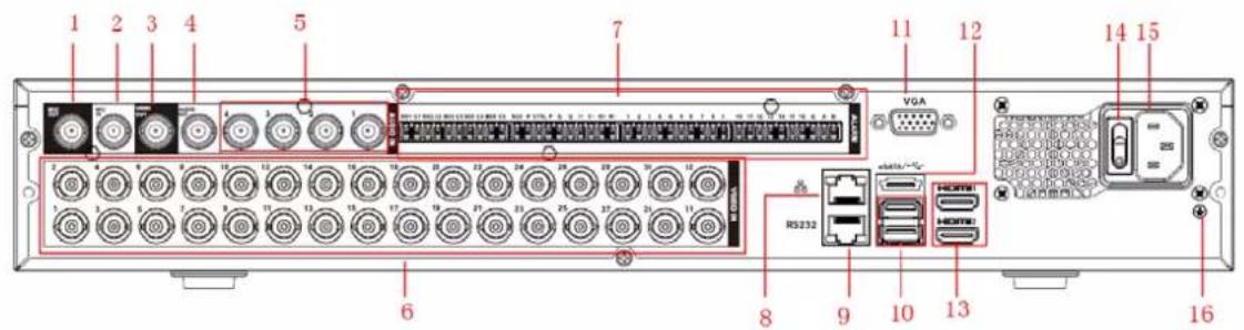
Figure 3-19 Rear panel (2)
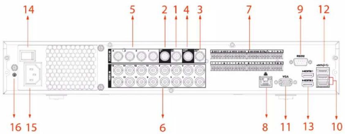
Figure 3-20 Rear panel (3)
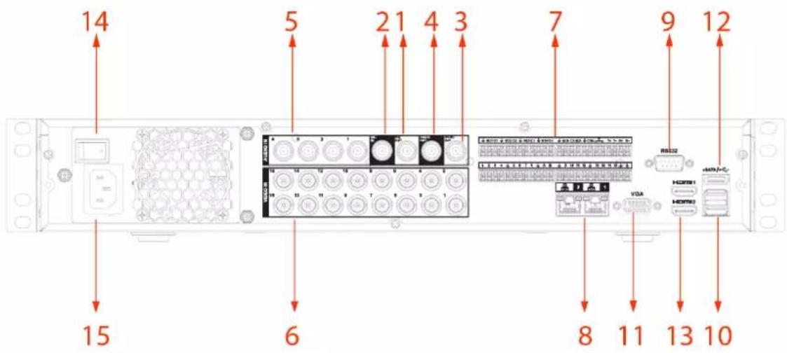
Table 3-17 Rear panel description
| No. | Port Name | Function |
| 1 | Audio output port (MIC OUT) | Two-way talk output port which outputs the analog audio signal to the devices such as the sound box. |
| 2 | Audio input port (MIC IN) | Two-way talk input port which receives the analog audio signal output from the devices such as microphone, pickup. |
| 3 Video | output port | Connect to video output devices such as TV. |
| 4 | Audio output port | Outputs the analog audio signal to the devices such as the sound box. |
| 5 | Audio input port | Receives the analog audio signal output from the devices such as microphone. |
| 6 | Video input port | Connect to analog camera to input video signal. |
| 7 | Alarm input port 1-16 | Four groups of alarm output ports (Group 1: port 1 to port 4; Group 2: port 5 to port 8; Group 3: port 9 to port 12; Group 4: port 13 to port 16). These ports receive the signal from the external alarm source. There are two types; NO (Normally Open) and NC (Normally Closed).When your alarm input device is using external power, make sure the device and the NVR have the same ground. |
| Alarm output port 1-5 (NO1-NO5; C1-C5; NC5) | Five groups of alarm output ports. (Group 1: port NO1-C1, Group 2: port NO2-C2, Group 3: port NO3-C3, Group 4: port NO4-C4, Group 5: port NO5, C5, NC5). These ports output alarm signal to the alarm device. Make sure power supply to the external alarm device.NO: Normally open alarm output port.C: Alarm output public end.NC: Normally closed alarm output port. | |
| RS-485 communication port | You can connect to the control devices such as speed dome PTZ.RS-485_A port is connected by the cable A and RS-485_B is connected to the cable B. | |
| Four-wire full-duplex RS-485 port (T+, T-, R+, R-) | Four-wire full-duplex 485 port. T+ and T- is the output wire; R+ and R- is the input wire. | |
| Control power output (CTRL 12V) | Controls 12 VDC power output. It is to control the on-off alarm relay output. | |
| 12V power output port | Provides power to external devices such as camera and alarm device. Note the supplying power shall be below 1A. | |
| ± | Ground. | |
| 8 | Network port | Connects to Ethernet port. |
| 9 | RS-232 debug COM | It is for general COM debug to configure IP address or transfer transparent COM data. |
| 10 USB | port | Connects to the external devices such as keyboard, mouse, and USB storage device. |
| 11 VGA | video output | Outputs analog video signal. It can connect to the monitor to view analog video. |
| 12 eSATA | port | External SATA port which connects to the device with SATA port.Perform the jumper configuration when connecting HDD. |
| 13 HDMI | port | High definition audio and video signal output port. It outputs the same video source as VGA. It supports 4K resolution output and supports mouse operation and control.Note when the HDMI output resolution is 4K, the VGA output stops. |
| 14 | Power switch | Turns on/off the Device. |
| 15 | Power input port | Inputs power. |
| 16 | GND | Ground. |
3.2.8 DH-XVR1Bxx-I/DH-XVR1BxxH-I
Figure 3-21 Rear panel
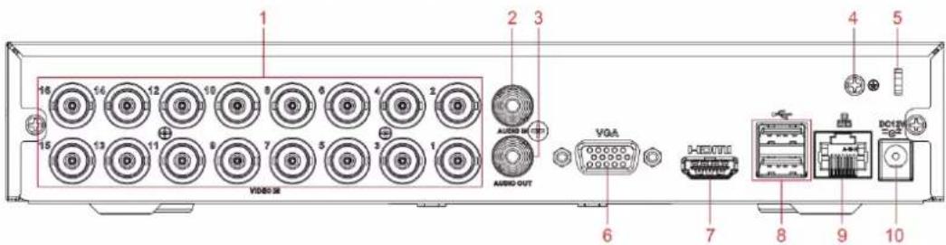
Table 3-18 Rear panel description
| No. | Port Name | Function |
| 1 | Video input port | Connect to analog camera to input video signal. |
| 2 | Audio input port | Receives the analog audio signal output from the devices such as microphone. |
| 3 Audio output port | Outputs the analog audio signal to the devices such as the sound box. | |
| 4 GND | Ground. | |
| 5 | Power cable fastener | Use clamp to secure the power cable on the DVR in case there is any loss. |
| 6 VGA video output | Outputs analog video signal. It can connect to the monitor to view analog video. | |
| 7 HDMI port | High definition audio and video signal output port. It outputs the same video source as VGA. It supports 4K resolution output and supports mouse operation and control.Note when the HDMI output resolution is 4K, the VGA output stops. | |
| 8 USB port | Connects to the external devices such as keyboard, mouse, and USB storage device. | |
| 9 | Network port | Connects to Ethernet port. |
| 10 | Power input port | Inputs power. |
3.2.9 DH-XVR51xxC-I3/DH-XVR51xxC-4KL-I3
Figure 3-22 Rear panel
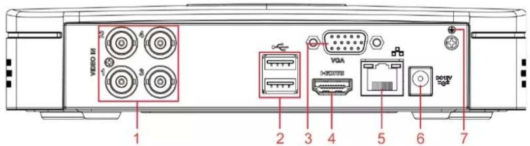
Table 3-19 Rear panel description
| No. | Port Name | Function |
| 1 | Video input port | Connects to analog camera to input video signal. |
| 2 USB port | Connects to external devices such as USB storage device, keyboard and mouse. | |
| 3 | VGA port | Outputs analog video data to the connected display with VGA port. |
| 4 HDMI | port | High definition audio and video signal output port.The port outputs the uncompressed high definition video and multi-channel audio data to the connected display with HDMI port. |
| 5 | Network port | Connects to Ethernet port. |
| 6 | Power input port | Inputs 12 VDC power. |
| 7 | Ground terminal. | |
3.3 Remote Control Operations

Note the remote control is not our standard accessory and might not be included in the accessory bag. It is supplied dependent on the model you purchased.
Figure 3-23 Remote control
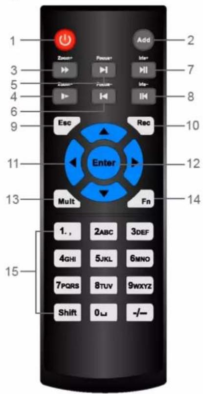
Table 3-20 Remote control description
| No. | Name | Function |
| 1 | Power button | Press this button to boot up or shut down the device. |
| 2 Address | Press this button to input device serial number, so that you can control the Device. | |
| 3 | Forward | Multi-step forward speed and normal speed playback. |
| 4 | Slow motion | Multi-step slow motion speed or normal playback. |
| 5 | Next record | In playback state, press this button to play back the next video. |
| 6 | Previous record | In playback state, press this button to play back the previous video. |
| 7 Play/Pause | In normal playback state, press this button to pause playback.In pause state, press this button to resume to normal playback.In live view window page, press this button to enter video search menu. | |
| 8 Reverse/pause | In the reverse playback state, press this button to pause reverse playback. | |
| In the reverse playback pause state, press this button to resume to playback reversing state. | ||
| 9 Esc. | Go back to previous menu or cancel current operation (close front page or control). | |
| 10 Record | Start or stop record manually.In record page, use the direction buttons to select the channel that you want to record.Press this button for at least 1.5 seconds, and the manual record page will be displayed. | |
| 11 Direction keys | Switch between current activated controls by going left or right.In playback state, the keys control the playback progress bar.Aux function (such as operating the PTZ menu). | |
| 12 Enter/menu key | Confirms an operation.Go to the OK button.Go to the menu. | |
| 13 | Multiple-window switch | Switch between multiple-window and one-window. |
| 14 Fn | In single-channel monitoring mode, press this button to display the PTZ control and color setting functions.Switch the PTZ control menu in PTZ control page.In motion detection page, press this button with direction keys to complete setup.In text mode, press and hold this button to delete the last character. To use the clearing function: Long press this button for 1.5 seconds.In HDD menu, switch HDD recording time and other information as indicated in the pop-up message. | |
| 15 | Alphanumeric keys | Input password, numbers.Switch channel.Press Shift to switch the input method. |
3.4 Mouse Operations

The operations are based on the considerations for right-handed users.
Table 3-21 Mouse operations
| Operation Function | |
| Click left mouse button | Password input dialogue box pops up if you have not logged in yet. In live view window page, you can go to the main menu. |
| When you have selected one menu item, click it to view menu content. | |
| Implement the control operation. | |
| Modify checkbox or motion detection status. | |
| Click combo box to pop up drop-down list. | |
In text box, click the corresponding button on the panel to enter a numeral or English character (small/capitalized).In English input mode: Click to enter a backspace and click to delete the previous character.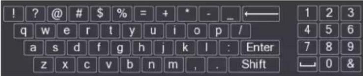 In numeral input mode: Click to clear and click to delete the previous character. In numeral input mode: Click to clear and click to delete the previous character.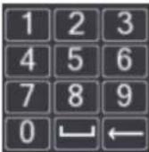 | |
| Double-click left mouse button | Implement special control operations such as double-click one item in the file list to play back the video. |
| In multiple-window mode, double-click one channel to view in full-window.Double-click current video again to go back to previous multiple-window mode. | |
| Right-click | Right-click in live view window page, the shortcut menu is displayed. For different series product, the shortcut menu may vary. |
| Exit current menu without saving the modification. | |
| Click scroll wheel button | In numeral input box: Increase or decrease numeral value. |
| Switch the items in the combo box. | |
| Page up or page down. | |
| Point to select and move | Select current control and move it. |
| Dragging a selection box with left mouse button | Select motion detection zone. |
| Select privacy mask zone. |
4 Connection
This chapter introduces the typical connection diagrams and ports connections.
4.1 Typical Connection Diagram

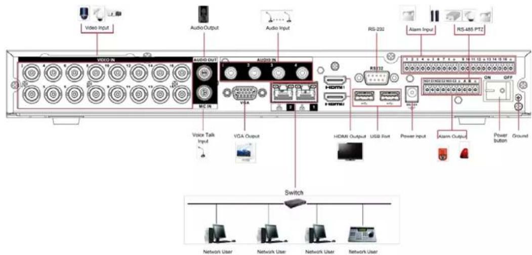
The following figure is for reference only and might differ from the actual product.
Figure 4-1 Connection diagram
4.2 Connecting to Video and Audio Input and Output
4.2.1 Video Input
The video input port is BNC. The input video format includes: PAL/NTSC BNC (1.0 V _P-P , 75 Ω).
The video signal should comply with your national standards.
The input video signal shall have high SNR, low distortion; low interference, natural color, and suitable lightness.
Guarantee the stability and reliability of the camera signal
The camera shall be installed in a cool, dry place away from the conditions such as direct sunlight, inflammable, and explosive substances.
The camera and the DVR should have the same grounding to ensure the normal operation of the camera.
Guarantee stability and reliability of the transmission line
Use high quality, sound shielded BNC. Select suitable BNC model according to the transmission distance.
If the distance is too long, you should use twisted pair cable, and you can add video compensation devices or use optical fiber to ensure video quality.
You should keep the video signal away from the strong electromagnetic interference, especially the high tension current.
Keep connection lugs in well contact
The signal line and shielded wire should be fixed firmly and in well connection. Avoid dry joint, lap welding, and oxidation.
4.2.2 Video Output
Video output includes a BNC (PAL/NTSC1.0 V_P-P , 75 ) output, a VGA output, and HDMI output. System supports BNC, VGA and HDMI output at the same time.
When you are using pc-type monitor to replace the monitor, pay attention to the following points:
- To defer aging, do not allow the pc monitor to run for a long time.
● Regular demagnetization will keep device maintain proper status. - Keep it away from strong electromagnetic interference devices.
Using TV as video output device is not a reliable substitution method. You also need to reduce the working hour and control the interference from power supply and other devices. The low quality TV may result in device damage.
4.2.3 Audio Input
This series of products audio input port adopt BNC port.
Due to high impedance of audio input, use active sound pick-up.
Audio transmission is similar to video transmission. Try to avoid interference, dry joint, loose contact and it shall be away from high tension current.
4.2.4 Audio Output
The audio output signal parameter is usually over 200 mv 1 KΩ (BNC or RCA). It can directly connect to low impedance earphone, active sound box or amplifier-drive audio output device.
If the sound box and the pick-up cannot be separated spatially, it is easy to arouse squeaking. In this case you can adopt the following measures:
- Use better sound pick-up with better directing property.
- Reduce the volume of the sound box.
- Using more sound-absorbing materials in decoration can reduce voice echo and improve acoustics environment.
- Adjust the layout of speaker and pickup to reduce squeaking.
4.3 Connecting to Alarm Input and Output
Read the followings before connecting.
Alarm input
● Make sure alarm input mode is grounding alarm input.
- Grounding signal is needed for alarm input.
- Alarm input needs the low level voltage signal.
- Alarm input mode can be either NC (Normally Closed) or NO (Normally Open).
- When you are connecting two DVRs or you are connecting one DVR and one other device, use a relay to separate them.
Alarm output
The alarm output port should not be connected to high power load directly (It shall be less than 1A) to avoid high current which might result in relay damage. Use the contactor to realize the connection between the alarm output port and the load. The next device connected to the port must meet the fire enclosure requirements.
How to connect PTZ decoder
- Ensure the decoder has the same grounding with DVR; otherwise the PTZ might not be controlled. Shielded twisted wire is recommended and the shielded layer is used to connect to the grounding.
- Avoid high voltage. Ensure proper wiring and some thunder protection measures.
- For too long signal wires, 120 Ω should be parallel connected between A, B lines on the far end to reduce reflection and guarantee the signal quality.
- "485 A, B" of DVR cannot parallel connect with "485 port" of other device.
- The voltage between of A, B lines of the decoder should be less than 5 V.
Make sure the front-end device has soundly earthed
Improper grounding might result in chip damage.
4.3.1 Introducing Alarm Port

The alarm input ports are dependent on the model you purchased.
Figure 4-2 Alarm ports

| Icon Description | |
| 1, 2, 3, 4, 5, 6, 7, 8, 9, 10, 11, 12, 13, 14, 15, 16 | ALARM 1 to ALARM 16. The alarm becomes active in low voltage. |
| NO1 C1, NO2 C2, NO3 C3 | There are four groups of normally open activation output (on/off button). |
 | Ground cable. |
| 485 A/B | 485 communication port. They are used to control devices such as decoder. 120 Ω should be parallel connected between A, B lines if there are too many PTZ decoders. |
4.3.2 Alarm Input
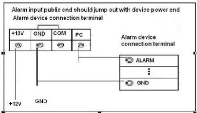
Refer to the following figure for more information.
- Grounding alarm inputs which includes NO (Normally Open) and NC (Normally Closed) type.
- Parallel connect COM end and GND end of the alarm detector (Provide external power to the alarm detector).
- Parallel connect the Ground of the DVR and the ground of the alarm detector.
- Connect the NC port of the alarm sensor to the DVR alarm input (ALARM).
- Use the same ground with that of DVR if you use external power to the alarm device.
Figure 4-3 Alarm input
flowchart
graph TD
    A["+12V"] --> B["GND"]
    B --> C["COM"]
    C --> D["PC"]
    E["+12V"] --> F["GND"]
    F --> G["Alarm device connection terminal"]
    H["Alarm input public end should jump out with device power end"] --> I["Alarm device connection terminal"]
4.3.3 Alarm Output
- Provide external power to external alarm device.
• To avoid overloading, read the following relay parameters table carefully.
• RS-485 A/B cable is for the A/B cable of the PTZ decoder.
4.3.4 Alarm Output Relay Parameters

Refer to the actual product for relay model information.
Table 4-2 Alarm output relay parameters
| Model | HFD23/005-1ZS | HRB1-S-DC5V | |
| Material of the touch | AgNi+ gold-plating | AuAg10/AgNi10/CuNi30 | |
| Rating (Resistance Load) | 30 VDC 1 A/125 VAC 0.5 A | 24 VDC 1 A/125 VAC 2 A | 24 VDC 1 A/125 VAC 2 A |
| 62.5 VA/30 W | 250 VA/48 W | 250 VA/48 W | |
| 125 VAC/60 VDC | 125 VAC/60 VDC | 125 VAC/60 VDC | |
| 2 A 2 A 2 A | |||
| Insulation | 400 VAC 1 minute | 500 VAC 1 minute | 500 VAC 1 minute |
| 1000 VAC 1 minute | 1000 VAC 1 minute | 1000 VAC 1 minute | |
| Turn-on Time | 5 ms max | 5 ms max | |
| Turn-off Time | 5 ms max | 5 ms max | |
| Longevity | 1 × 10^7 times(300 times/MIN) | 5 × 10^6 times(300 times/MIN) | 5 × 10^6 times(300 times/MIN) |
| 1 × 10^5 times(30 times/MIN) | 2.5 × 10^4 times(30 times/MIN) | 2.5 × 10^4 times(30 times/MIN) | |
| Working Temperature | -30 °C to +70 °C | -40 °C to +70 °C | |
5 Local Configurations
Read the following notes prior to using the Device.

- The figures in the Manual are used for introducing the operations and only for reference. The actual interface might be different dependent on the model you purchased.
- The Manual is a general document for introducing the product, so there might be some functions described for the Device in the Manual not apply to the model you purchased.
- Conventions for mouse operations on a menu.
◇ Click: On the menu, click the mouse once on an option to enter the option setting.
Right-click: On any page, right-click the mouse once to return to the previous level. For details about mouse operations, see "3.4 Mouse Operations".
5.1 Initial Settings
5.1.1 Booting up

- Ensure the input voltage corresponds to the power requirement of the Device. Power on the Device after the power cable is properly connected.
- To protect the Device, connect the Device with the power cable first, and then connect to the power source.
- To ensure the stable work of the Device and the external devices connected to the Device and to prolong the HDD life, it is recommended to refer to the national related standard to use the power source that provides stable voltage with less interference from ripples. UPS power source is recommended.
Step 1 Connect the Device to the monitor.
Step 2 Plug in the power cable to the Device.
Step 3 Press the power button to turn on the Device. The power indicator light is on.
On the connected monitor, the live view screen is displayed by default. If you turn on the Device during the time period that is configured for recording, the system starts recording after it is turned on, and you will see the icon indicating recording status is working in the specific channels.
5.1.2 Initializing the Device
When booting up for the first time, you need to configure the password information for admin (by default).

To secure the Device, we strongly recommend you properly keep the password for admin and modify it regularly.
Step 1 Turn on the Device.
Figure 5-1 Location, language and video standard
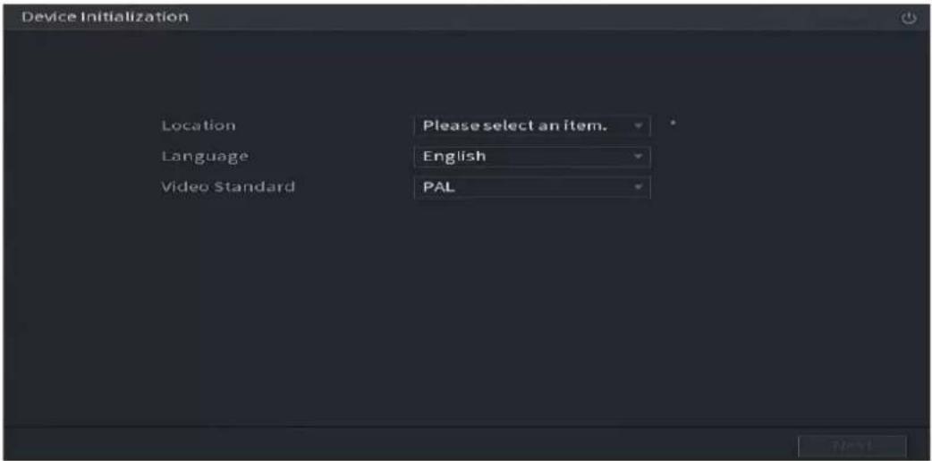
Step 2 Select your location from the drop-down list, then language and video standard will match your location automatically. You can change the language and video standard manually.
Step 3 Click Next.
Figure 5-2 License agreement
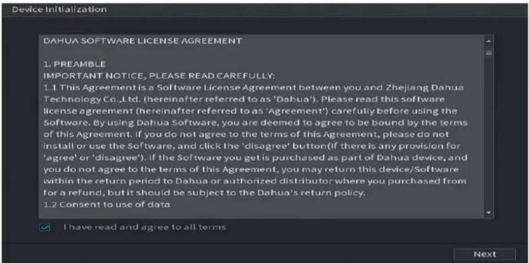
Step 4 Select the checkbox that I have read and agree to all terms, and then click Next.
Figure 5-3 Time
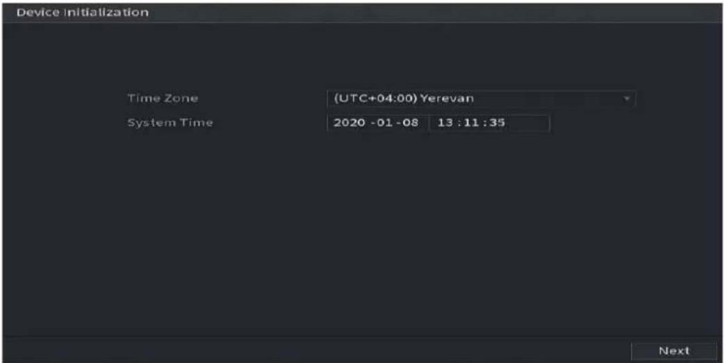
Step 5 Select system zone, configure system time, and then click Next.
Figure 5-4 Enter password
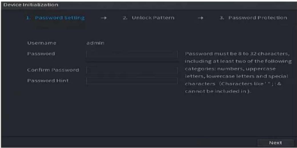
Step 6 Configure the password information for admin.
Table 5-1 Password information
| Parameter Description | |
| User | By default, the user isadmin. |
| Password | In thePasswordbox, enter the password for admin.The new password can be set from 8 characters through 32 characters and contains at least two types from number, letter and special characters (excluding", "", ";", ";" and "&"). |
| Confirm Password | |
| Prompt Hint | In thePrompt Hintbox, enter the information that can remind you of the password.On the login page, click , the prompt will display to help you find back the password. |
Step 7 Click Next.
Figure 5-5 Unlock pattern
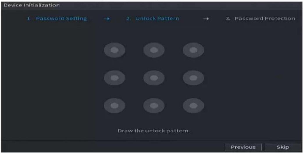
Step 8 Draw an unlock pattern.

- The pattern that you want to set must cross at least four points.
- If you do not want to configure the unlock pattern, click Skip.
- Once you have configured the unlock pattern, the system will require the unlock pattern as the default login method. If you skip this setting, enter the password for login.
Figure 5-6 Password protection
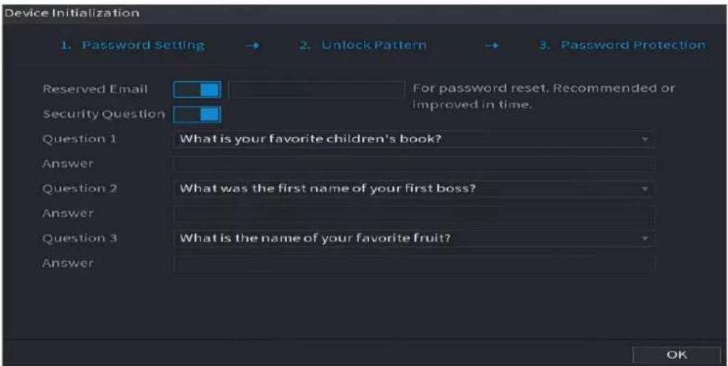
Step 9 Configure the protection parameters for password.
After configuration, if you forget the password for admin user, you can reset the password through the reserved email address or security questions. For details about resetting the password, see "5.1.3 Resetting Password".
If you do not want to configure the settings, disable the email address and security questions functions on the page.
Table 5-2 Password protection parameters
| Password Protection Mode | Description |
| Reserved Email | Enter the reserved email address.In theReserved Emailbox, enter an email address for password reset. If you forget the password, enter the security code that you will get from this reserved email address to reset the password of admin. |
| Security Questions | Configure the security questions and answers.If you forget the password, enter the answers to the questions can make you reset the password. |
 If you want to configure the email or security questions function later or you want to change the configurations, selectMain Menu > ACCOUNT > Password Reset. If you want to configure the email or security questions function later or you want to change the configurations, selectMain Menu > ACCOUNT > Password Reset. | |
Step 10 Click OK to complete the settings.
Step 11 Select I have read and agree to all terms checkbox.
Step 12 Click Next.
The Startup Wizard page is displayed. For details about quick settings during startup, see "5.1.4 Setting Up with the Startup Wizard".
5.1.3 Resetting Password
You can reset the password by the following methods when you forget the password for admin account.
- If the password reset function is enabled, you can use mobile phone to scan the QR code to reset the password. For details, see "5.1.3.2 Resetting Password on Local Interface".
- If the password reset function is disabled, there are two situations:
If you configured security questions, you can find back the password by the security questions.
If you did not configure the security questions, you can only use the reset button on the mainboard to restore the Device to factory default. For details, see "5.1.3.3 Using Reset Button on the Mainboard".

The reset button is available on select models.
5.1.3.1 Enabling Password Reset Function
Step 1 Select Main Menu > Account > Password Reset.
Figure 5-7 Password reset
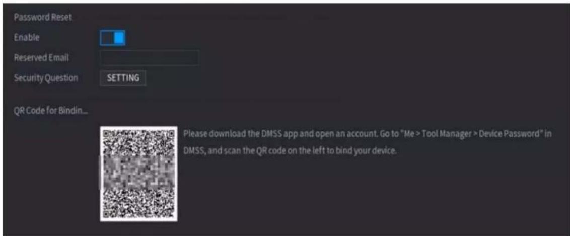
Step 2 Enable the Password Reset function.

This function is enabled by default.
Step 3 Click Apply to save the settings.
When Password reset function is disabled, you can retrieve password through following ways:
- You can retrieve password through resetting password on local interface or using Reset button on the mainboard when the device supports Reset button.
- You can only retrieve password through resetting password on local interface (make sure that security questions are preset) when the device does not support Reset button.
5.1.3.2 Resetting Password on Local Interface
Step 1 Enter the login page.
- If you have configured unlock pattern, the unlock pattern login page is displayed. Click Forgot Pattern, the password login page is displayed.
- If you did not configure unlock pattern, the password login page is displayed. Click to display the password with plaintext.

To log in from other user account, on the unlock pattern login page, click Switch User; or on the password login page, in the User Name list, select other users to login.
Figure 5-8 Login (1)
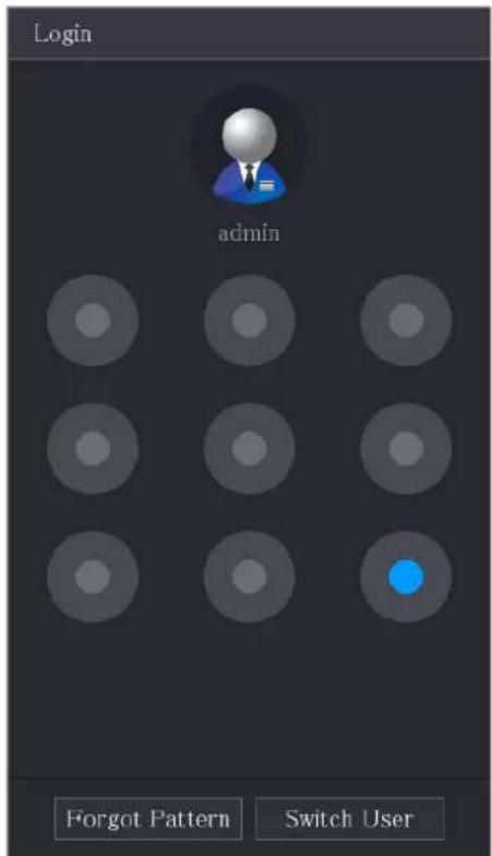
Figure 5-9 Login (2)
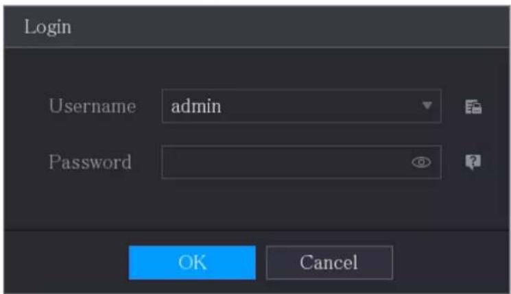
Step 2 Click

- If you have set the reserved email address, the Prompt message page is displayed.
- If you did not set the reserved email address, the email entering page is displayed. See Step 3. Enter the email address, and then click Next, the Prompt message page is displayed.
Figure 5-10 Note
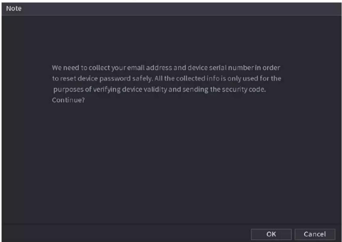
Step 3 Click OK.

After clicking OK, the system will collect your information for password reset, and the information includes but not limited to email address, and device serial number. Read the prompt carefully before clicking OK.
Figure 5-11 Reset mode (email)
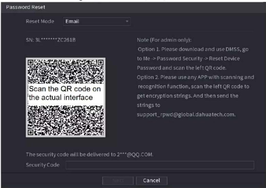
Figure 5-12 Reset mode (app)
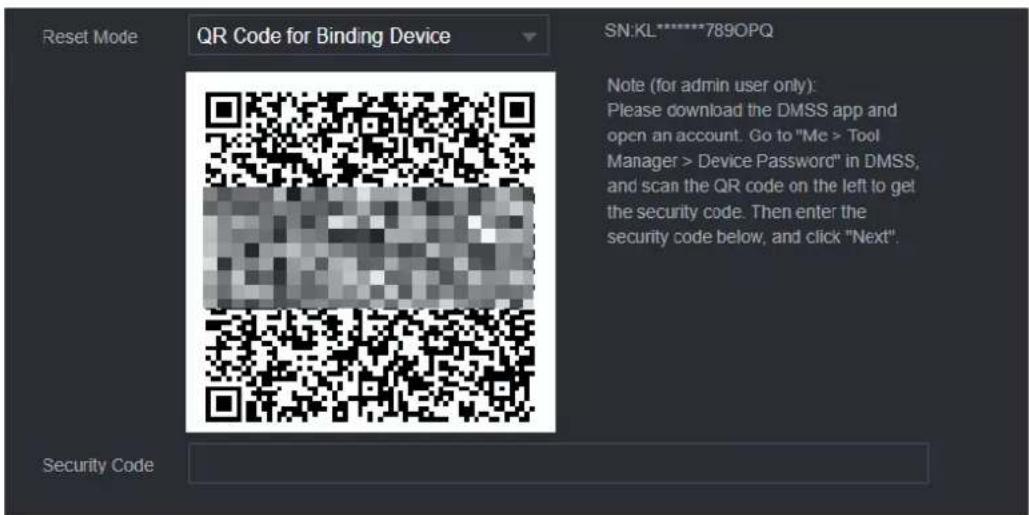
Step 4 Reset the password.
- QR code
Follow the on-screen instructions to get the security code in your reserved email address. In the Security Code box, enter the security code.

- You can get the security code twice by scanning the same QR code. If you need to get the security code once again, refresh the page.
- Use the security code received in your email box to reset the password within 24 hours; otherwise the security code becomes invalid.
- App
Select QR Code for Binding Device as Reset Mode, and then follow the on-screen instructions to get the security code on your DMSS app. In the Security Code box, enter the security code.
- Security questions
1) For Reset Mode, select Security Questions.

If you did not configure the security questions before, in the Reset Type list, there will be no Security Questions.
2) In the Answer box, enter the correct answers.
Figure 5-13 Security questions
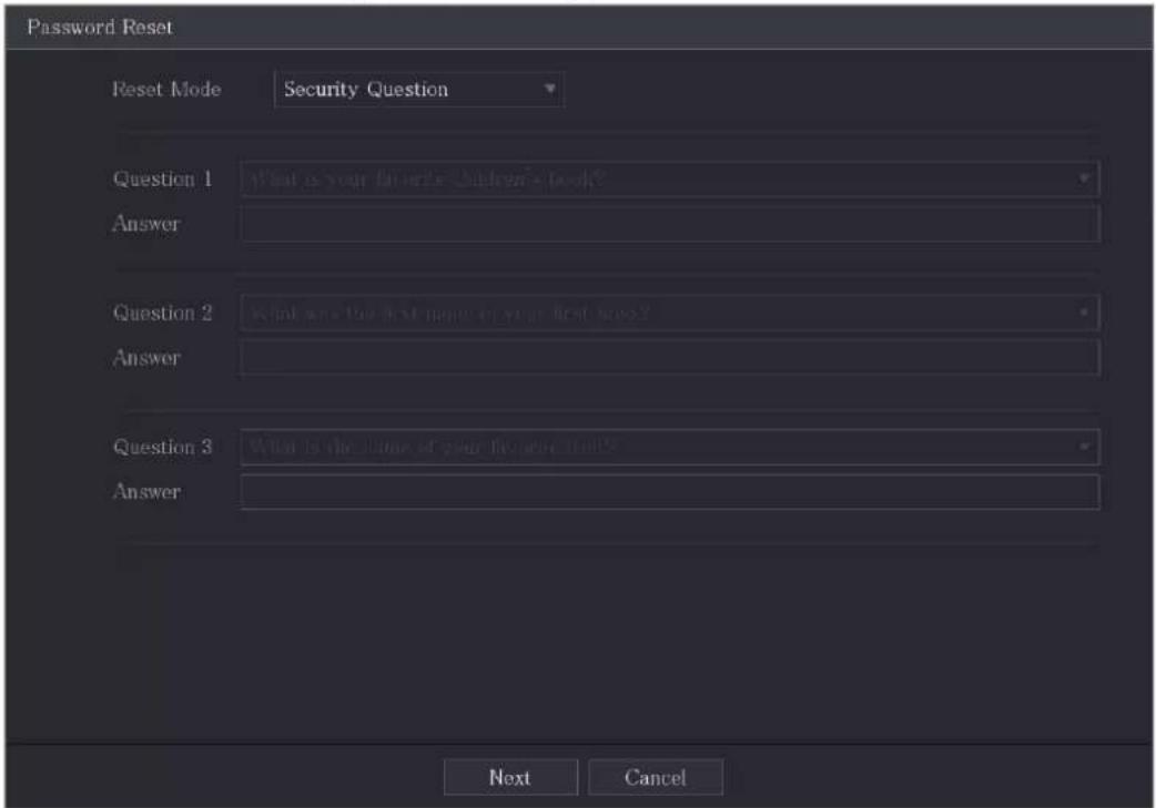
Step 5 Click Next.
Figure 5-14 New password
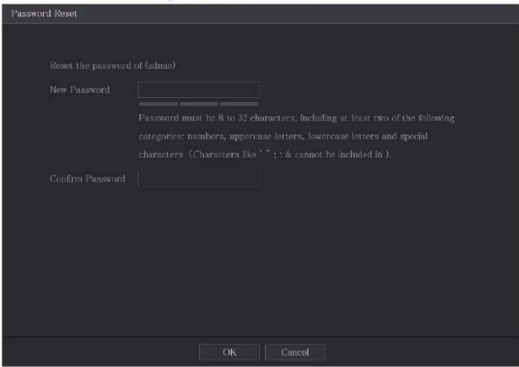
Step 6 In the New Password box, enter the new password and enter it again in the Confirm Password box.
Step 7 Click Save. The password resetting is started. After resetting is completed, a pop-up message is displayed.
Step 8 Click OK.
A pop-up message is displayed asking if you want to sync the password with the remote devices.
- Click Cancel, the resetting is finished.
- Click OK, the Sync Info page is displayed.
Figure 5-15 Sync password
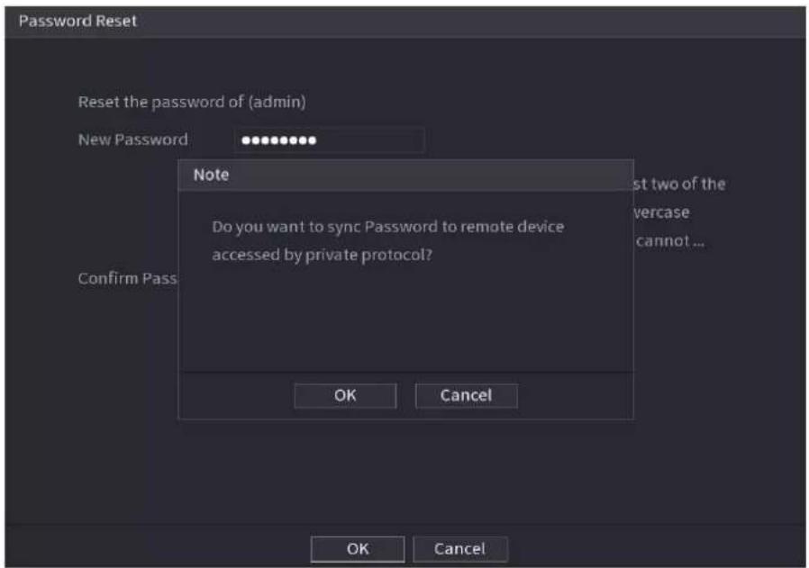

This message appears only when there are digital channels instead of only analog channels.
Figure 5-16 Sync info
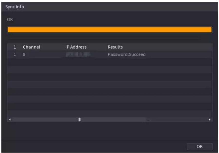
5.1.3.3 Using Reset Button on the Mainboard
You can always use the reset button on the mainboard to reset the Device to the factory default.

The reset button is available on select models.
Step 1 Disconnect the Device from power source, and then remove the cover panel. For details about removing the cover panel, see "2.2 Installing HDD".
Step 2 Find the reset button on the mainboard, and then press and hold the reset button for 5 seconds to 10 seconds.
Figure 5-17 Reset button
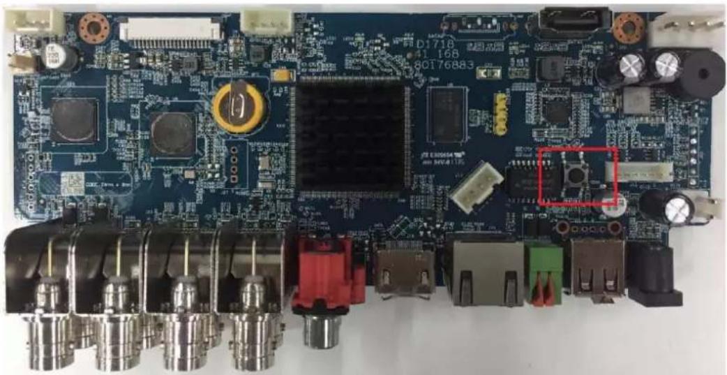
natural_image
Close-up of a printed circuit board with various electronic components and connectors (no readable text or symbols)Step 3 Reboot the Device.
After the Device is rebooted, the settings have been restored to the factory default. You can start resetting the password.
5.1.4 Setting Up with the Startup Wizard
5.1.4.1 Entering Startup Wizard
The Startup Wizard helps you configure the basic settings to set up the Device. After you have initialized the Device, the Startup Wizard page is displayed.
Figure 5-18 Startup wizard
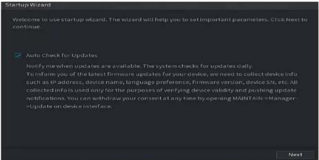

- If you select the Auto-check for updates checkbox, the system will notify you automatically when updates are available.
- After the auto-check function is enabled, to notify you to update timely, the system will collect the information such as IP address, device name, firmware version, and device serial number. The collected information is only used to verify the legality of the Device and push upgrade notices.
- If you clear the Auto-check for updates checkbox, the system will not perform automatic checks.
5.1.4.2 Configuring General Settings
You can configure the general settings for the Device such as Device name, language, and settings for instant playback.
You can also configure general settings by selecting Main Menu > SYSTEM > General > Basic.
Step 1 On the Startup Wizard page, click Next.
Figure 5-19 Basic
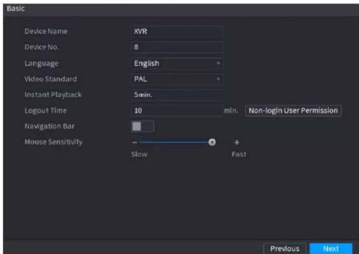
Step 2 Configure the basic settings parameters.
Table 5-3 Basic settings
| Parameter Description | |
| Device Name | In the Device Name box, enter the Device name. |
| Device No. | In the Device No. box, enter a number for the Device. |
| Language | In the Language list, select a language for the Device system. |
| Video Standard | In the Video Standard list, select PAL or NTSC according to your actual situation. |
| Instant Playback | In the Instant Playback box, enter the time length for playing back the recoded video.On the live view control bar, click the instant playback button to play back the recorded video within the configured time. |
| Logout Time | In the Logout Time box, enter the standby time for the Device. The Device automatically logs out when it is not working for the configured time period. You need to log in to the Device again.The value ranges from 0 to 60. 0 indicates there is not standby time for the Device.Click Monitor Channel(s) when logout. You can select the channels that you want to continue monitoring when you logged out. |
| Navigation Bar | Enable the navigation bar. When you click on the live view screen, the navigation bar is displayed. |
| Mouse Pointer Speed | Adjust the speed of double-click by moving the slider.The bigger the value is, the faster the double-clicking speed must be. |
5.1.4.3 Configuring Date and Time Settings
You can configure the system time, choose the time zone, set the daylight saving time, and enable the NTP server.
You can also configure date and time settings by selecting Main Menu > SYSTEM > General > Date &Time.
Step 1 After you have configured the general settings, on the General page, click Next.
Figure 5-20 Date&Time
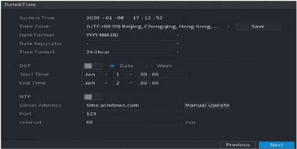
Step 2 Configure the settings for date and time parameters.
| Parameter Description | |
| System Time | In the System Time box, enter time for the system.Click the time zone list, you can select a time zone for the system, and the time in adjust automatically.⚠Do not change the system time randomly; otherwise the recorded video cannot be searched. It is recommended to avoid the recoding period or stop recording first before you change the system time. |
| Time Zone | In the Time Zone list, select a time zone for the system. |
| Date Format | In the Date Format list, select a date format for the system. |
| Date Separator | In the Date Separator list, select a separator style for the date. |
| Time Format | In the Time Format list, select 12-HOUR or 24-HOUR for the time display style. |
| DST | Enable the Daylight Saving Time function. Click Week or click Date. |
| Start Time | Configure the start time and end time for the DST. |
| End Time | |
| NTP | Enable the NTP function to sync the Device time with the NTP server. BookIf NTP is enabled, device time will be automatically synchronized with server. |
| Serve Address | In the Server Address box, enter the IP address or domain name of the corresponding NTP server.Click Manual Update , the Device starts syncing with the server immediately. |
| Port | The system supports TCP protocol only and the default setting is 123. |
| Interval | In the Interval box, enter the amount of time that you want the Device to sync time with the NTP server. The value ranges from 0 to 65535. |
5.1.4.4 Configuring Network Settings
You can configure the basic network settings such as net mode, IP version, and IP address of the Device.
You can also configure network settings by selecting Main Menu > NETWORK > TCP/IP.
Step 1 After you have configured the date and time settings, on the Date &Time page, click Next.
Figure 5-21 TCP/IP
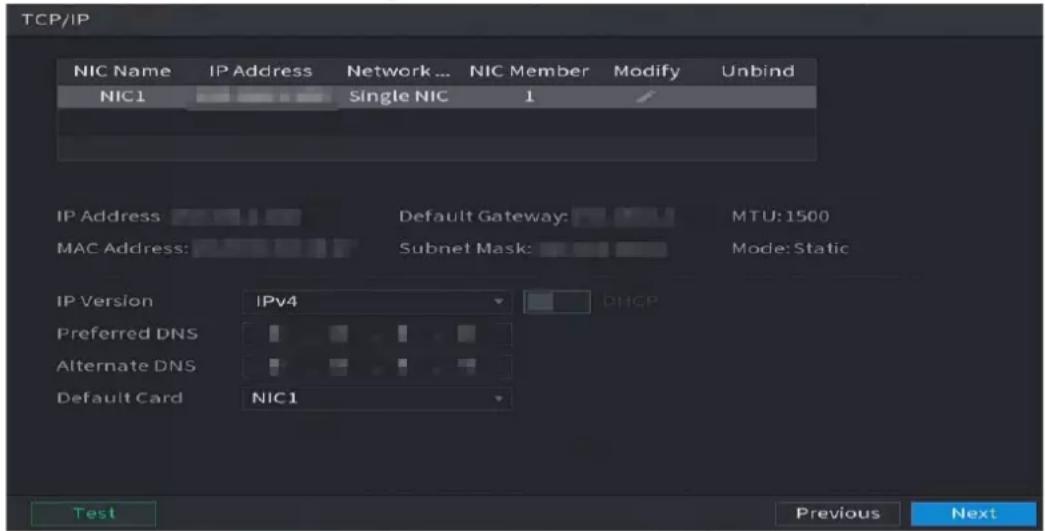
Step 2 Configure the settings for network parameters.
Table 5-4 Network parameters
| Parameter Description | |
| IP Version | In the IP Version list, you can select IPv4 or IPv6. Both versions are supported for access. |
| MAC Address | Displays the MAC address of the Device. |
| DHCP | Enable the DHCP function. The IP address, subnet mask and default gateway are not available for configuration once DHCP is enabled.If DHCP is effective, the obtained information will display in the IP Address box, Subnet Mask box and Default Gateway box. If not, all values show 0.0.0.0.If you want manually configure the IP information, disable the DHCP function first.If PPPoE connection is successful, the IP address, subnet mask, default gateway, and DHCP are not available for configuration. |
| IP Address | Enter the IP address and configure the corresponding subnet mask and default gateway. |
| Subnet Mask | |
| Default Gateway | IP address and default gateway must be in the same network segment. |
| DNS DHCP | Enable the DHCP function to get the DNS address from router. |
| Preferred DNS | In the Preferred DNS box, enter the IP address of DNS. |
| Alternate DNS | In the Alternate DNS box, enter the IP address of alternate DNS. |
| MTU | In the MTU box, enter a value for network card. The value ranges from 1280 byte through 1500 byte. The default is 1500.The suggested MTU values are as below.1500: The biggest value of Ethernet information package. This value is typically selected if there is no PPPoE or VPN connection, and it is also the default value of some routers, network adapters and switches.1492: Optimized value for PPPoE.1468: Optimized value for DHCP.1450: Optimized value for VPN. |
| Test | Click Test to test if the entered IP address and gateway are interworking. |
5.1.4.5 Configuring P2P Settings
You can add the Device into your cell phone client or the platform to manage.
You can also configure P2P function by selecting Main Menu > Network > P2P.

Make sure the DVR is connected into the Internet, and if yes, in the Status box of the P2P page, it shows Online.
Step 1 After you have configured the network settings, on the Network page, click Next.
Figure 5-22 P2P
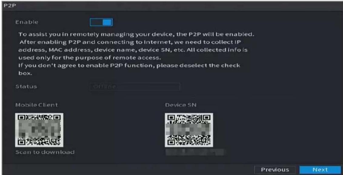
Step 2 Enable the P2P function.

After the P2P function is enabled and connected to the Internet, the system will collect your information for remote access, and the information includes but not limited to email address, MAC address, and device serial number.
You can start adding the device.
- Cell Phone Client: Use your mobile phone to scan the QR code to add the device into the Cell Phone Client, and then you can start accessing the Device.
- Platform: Obtain the Device SN by scanning the QR code. Go to the P2P management platform and add the Device SN into the platform. Then you can access and manage the device in the WAN. For details, refer to the P2P operation manual.

- You can also enter the QR code of Cell Phone Client and Device SN by clicking on the upper-right corner of the pages after you have entered the Main Menu.
- If selection of this function is canceled, the Note page is displayed. Choose to enable it or not according to your actual need.
Figure 5-23 Note
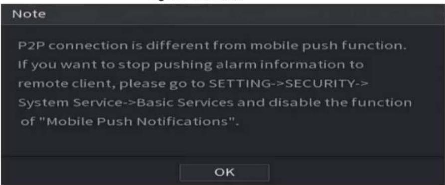
To use this function, take adding device into Cell Phone Client as an example.
Step 1 Use your cell phone to scan the QR code under Cell Phone Client to download the application.
Step 2 On your cell phone, open the application, and then tap
The menu is displayed. You can start adding the device.
1) Tap Device Manager.
Figure 5-24 Device manager
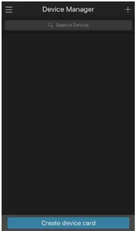
2) Tap + on the upper-right corner.
The page requiring device initialization is displayed. A pop-up message reminding you to make sure the Device is initialized is displayed.
3) Tap OK.
If the Device has not been initialized, Tap Device Initialization to perform initializing by following the onscreen instructions.
◇ If the Device has been initialized, you can start adding it directly.
4) Tap Add Device.

You can add wireless device or wired device. The Manual takes adding wired device as an example.
Figure 5-25 Add
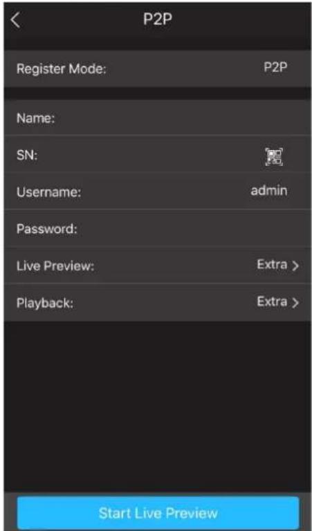
5) Tap P2P.
Figure 5-26 P2P
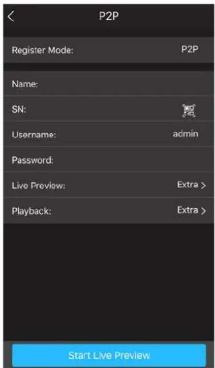
6) Enter a name for the DVR, the username and password, scan the QR code under Device SN.
7) Tap Start Live Preview. The Device is added and displayed on the live view page of the cell phone.
Figure 5-27 Live preview
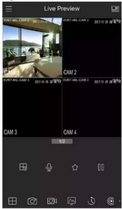
5.1.4.6 Configuring Encode Settings
You can configure the settings of main stream and sub stream for the Device.
You can also configure encode settings by selecting Main Menu > CAMERA > Encode > Audio/Video. Step 1 After you have configured the P2P settings, on the Audio/Video page, click Next.
Figure 5-28 Encode
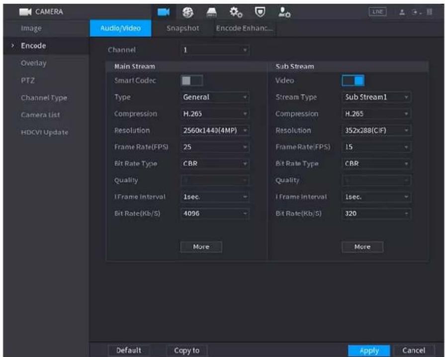
Step 2 Configure the settings for the main/sub streams parameters.
Table 5-5 Parameter description
| Parameter Description | |
| Channel | In the Channel list, select the channel that you want to configure the settings for. |
| Smart Codec | Enable the smart codec function. This function can reduce the video bit stream for non-important recorded video to maximize the storage space. |
| Type | Main Stream: In the Type list, select General, MD (Motion Detect), or Alarm.Sub Stream: This setting is not configurable. |
| Compression | In the Compression list, select the encode mode.H.265: Main profile encoding. This setting is recommended.H.264H: High profile encoding. Low bit stream with high definition.H.264: Main profile encoding.H.264B: Baseline profile encoding. This setting requires higher bit stream compared with other settings for the same definition. |
| Resolution | In the Resolution list, select resolution for the video.The maximum video resolution might be different dependent on your device model. |
| Frame Rate (FPS) | Configure the frames per second for the video. The higher the value is, the clearer and smoother the image will become. Frame rate changes along with the resolution.Generally, in PAL format, you can select the value from 1 through 25; in NTSC format, you can select the value from 1 through 30. However, the actual range of frame rate that you can select depends on the capability of the Device. |
| Bit Rate Type | In the Bit Rate Type list, select CBR (Constant Bit Rate) or VBR (Variable Bit Rate). If you select CBR, the image quality cannot be configured; if you select VBR, the image quality can be configured. |
| Quality | This function is available if you select VBR in the Bit Rate List.The bigger the value is, the better the image will become. |
| I Frame Interval | The interval between two reference frames. |
| Bit Rate (Kb/S) | In the Bit Rate list, select a value or enter a customized value to change the image quality. The bigger the value is, the better the image will become. |
| Video | Enable the function for sub stream. |
| Audio | Click More, the More page is displayed.Audio: This function is enabled by default for main stream. You need to manually enable it for sub stream 1. Once this function is enabled, the recorded video file is composite audio and video stream.Audio Source: In the Audio Source list, you can select Local and HDCVI.◇ Local: The audio signal is input from Audio In port.◇ HDCVI: The audio signal is input from HDCVI camera.Compression: In the Compression list, select a format that you need. |
| Audio Source | |
| Compression |
5.1.4.7 Configuring Snapshot Settings
You can configure the basic snapshot settings such as quantity of snapshot each time, channel(s) to take snapshot, and image size and quality of snapshot.
You can also configure general settings by selecting Main Menu > CAMERA > Encode > Snapshot.
For more information about snapshot settings, see "5.8 Configuring Snapshot Settings".
Step 1 After you have configured the encode settings, on the Encode page, click Next.
Figure 5-29 Snapshot
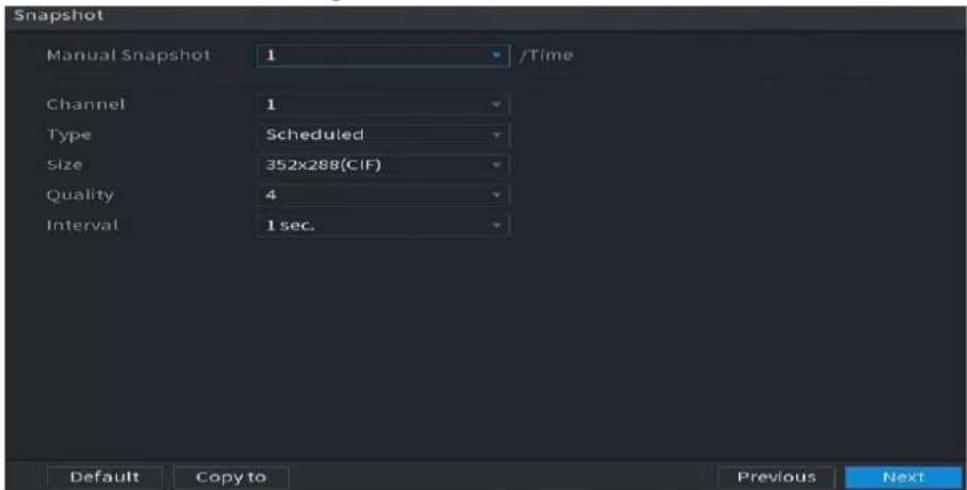
Step 2 Configure the settings for the snapshot parameters.
Table 5-6 Snapshot parameters
| Parameter Description | |
| Manual Snapshot | In theManual Snapshotlist, select how many snapshots you want to take each time. |
| Channel | In theChannellist, select the channel that you want to configure the settings for. |
| Type | In theModelist, you can selectHuman Face, Event, or Generalas the event type for which you want to take a snapshot.Scheduled: The snapshot is taken during the scheduled period.Event: The snapshot is taken when there is an alarm event occurs, such as motion detection event, video loss, and local alarms.Face Snapshot: The snapshot is taken when the face is detected. The face detection function is support only with the Channel 1. |
| Size | In theSizelist, select a value for the image. The bigger the value is, the better the image will become. |
| Quality | Configure the image quality by 6 levels. The higher the level is, the better the image will become. |
| Interval | Configure or customize the snapshot frequency. |
5.1.4.8 Configuring Basic Storage Settings
You can configure the settings for the situations when HDD is full, file length and time length of recorded video, and the settings if to auto-delete the old files.
You can also configure basic storage settings by selecting Main Menu > STORAGE > Basic. Step 1 After you have configured the encode settings, on the Snapshot page, click Next.
Figure 5-30 Basic
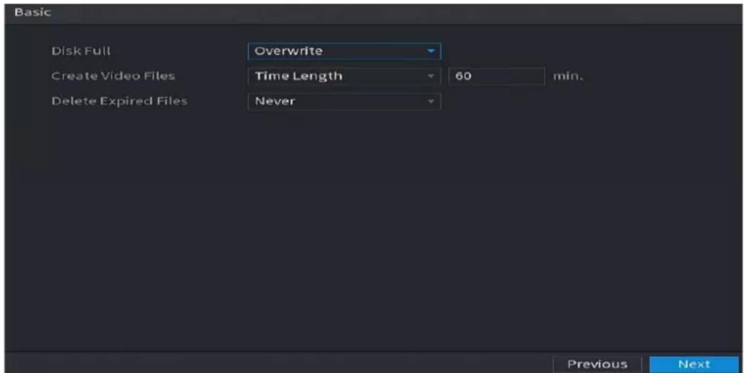
Step 2 Configure the basic storage settings parameters.
Table 5-7 Basic storage settings
| Parameter Description | |
| Disk Full | Configure the settings for the situation when all the read/write discs are full, and there are no more free discs.SelectStopto stop recording.SelectOverwriteto overwrite the recorded video files always from the earliest time.The locked recorded video files will not be overwritten. |
| Create Video Files | Configure the time length and file length for each recorded video. |
| Delete Expired Files | Configure whether to delete the old files and if yes, in theDelete Expired Fileslist, selectCustomto configure the time length for how long you want to keep the old files. |
5.1.4.9 Configuring Recorded Video Storage Schedule
You can configure the schedule for the recorded video such as channels to record, alarm settings, and the armed period.
You can also configure recorded video storage settings by selecting Main Menu > STORAGE > Schedule > Record.
Step 1 After you have configured the basic storage settings, on the Basic page, click Next.
Figure 5-31 Record
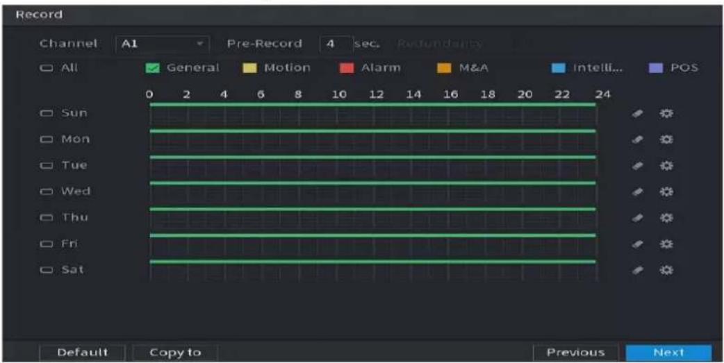
Step 2 Configure the record settings parameters.
| Parameter Description | |
| Channel | In the Channel list, select a channel to record the video. |
| Pre-record | In the Pre-record list, enter the amount of time that you want to start the recording in advance. |
| Redundancy | If there are several HDDs installed to the Device, you can set one of the HDDs as the redundant HDD to save the recorded files into different HDDs. In case one of the HDDs is damaged, you can find the backup in the other HDD.Select Main Menu > STORAGE > Disk Manager, and then set a HDD as redundant HDD.Select Main Menu > STORAGE > Schedule > Record, and then select the Redundancy checkbox.If the selected channel is not recording, the redundancy function takes effect next time you record no matter you select the checkbox or not.If the selected channel is recording, the current recorded files will be packed, and then start recording according to the new schedule.This function is available on select models.The redundant HDD only back up the recorded videos but not snapshots. |
| Event type | Select the checkbox of the event type which includes General, Motion (motion detect, video loss, tempering, diagnosis), Alarm (IoT alarms, local alarms, alarms from alarm box, IPC external alarms, IPC Offline alarms), M&A, Intelligent (IVS events, face detection), and POS. |
| Period | Define a period during which the configured recording setting is active.The system only activates the alarm in the defined period. |
| Copy | Click Copy to copy the settings to other channels. |
Step 3 Define the video recording period by drawing or editing. By default, it is active all the time.
- Define the period by drawing.
1) Select the checkbox of event type.
Figure 5-32 Event type

2) Define a period. The system supports maximum six periods.
Define for the whole week: Click ☐ next to All, all the icon switches to ☑, you can define the period for all the days simultaneously.
Define for several days of a week: Click ☐ before each day one by one, the icon switches to ☑. You can define the period for the selected days simultaneously.
3) On the timeline, drag to define a period. The Device starts recoding the selected event type in the defined period.
Figure 5-33 Timeline
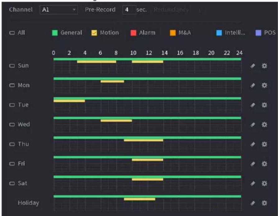
bar
| Day | All | General | Motion | Alarm | M&A | Intelli... | POS | |---|---|---|---|---|---|---|---| | Sun | 0 | 8 | 14 | 0 | 0 | 0 | 0 | | Mon | 0 | 0 | 6 | 0 | 0 | 0 | 0 | | Tue | 0 | 0 | 4 | 0 | 0 | 0 | 0 | | Wed | 0 | 0 | 9 | 0 | 0 | 0 | 0 | | Thu | 0 | 0 | 13 | 0 | 0 | 0 | 0 | | Fri | 0 | 0 | 12 | 0 | 0 | 0 | 0 | | Sat | 0 | 0 | 11 | 0 | 0 | 0 | 0 | | Holiday | 0 | 0 | 11 | 0 | 0 | 0 | 0 |The color bar indicates the event type that is effective in a defined period:

- Recording priority in case of event types are overlapped: M&A > Alarm > Intelligent > Motion > General.
- Select the checkbox of event type, and then click to clear the defined period.
- When selecting MD&Alarm, the MD and Alarm checkboxes will be cleared respectively.
- Define the period by editing. Take Sunday as an example.
1) Click.

Figure 5-34 Period
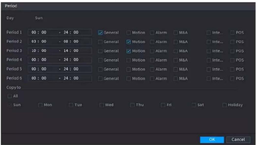
2) Enter the time frame for the period and select the event checkbox.
◇ There are six periods for you to set for each day.
Under Copy to, select All to apply the settings to all the days of a week, or select specific day(s) that you want to apply the settings to.
3) Click OK to save the settings.
Step 4 Click OK to complete the settings.

- Click Copy to copy the settings to other channels.
- After configuring the recording schedule settings, you need to perform the following operations to start recording according to the defined schedule.
Enable the alarm event and configure the settings for the recording channel. For details, see "5.10 Alarm Events Settings".
◇ You need to enable the recording function, see "5.9.1 Enabling Record Control".
5.1.4.10 Configuring Snapshot Storage Schedule
You can configure the storage schedule for the snapshot such as channels to take snapshot, alarm settings, and the armed period.
You can also configure snapshot storage settings by selecting Main Menu > STORAGE > Schedule > Snapshot.
Step 1 After you have configured the video recording settings, on the Record page, click Next.
Figure 5-35 Snapshot
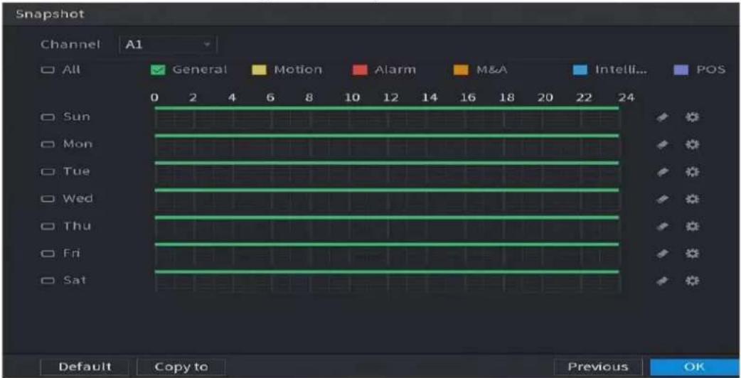
Step 2 Configure the snapshot settings parameters.
| Parameter Description | |
| Channel | In the Channel list, select a channel to take a snapshot. |
| Event type | Select the checkbox of the event type which includes General, Motion, Alarm, M&A, Intelligent, and POS. |
| Period | Define a period during which the configured snapshot setting is active. For details about defining a period, see "5.1.4.9 Configuring Recorded Video Storage Schedule". |
| Copy | Click Copy to copy the settings to other channels. |
Step 3 Click OK.
Step 4 Click OK.
The live view screen is displayed. The setting up with startup wizard is completed. You can start using the Device.
Step 5 (Optional) After the setting with startup wizard is completed, if the connected HDMI display resolution is inconsistent with default resolution (1280 × 1024), a dialog box will pop up. Choose to switch the resolution or not.
Figure 5-36 Change resolution
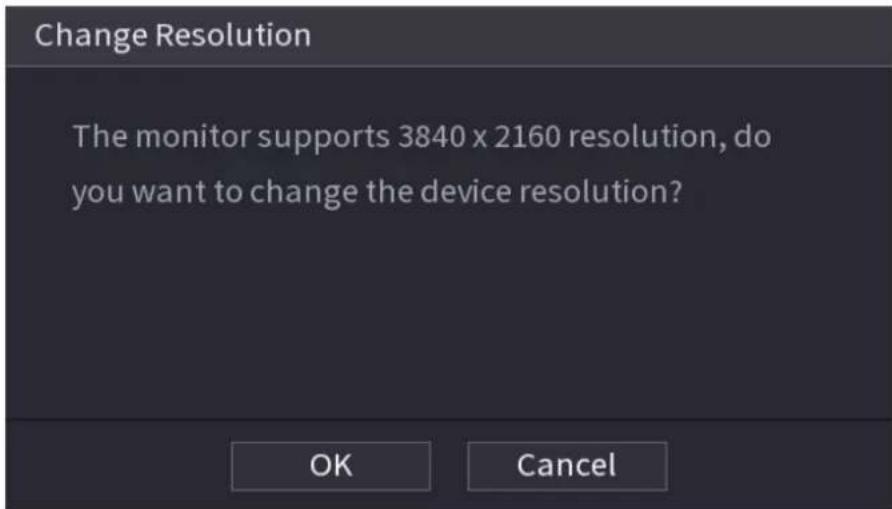
5.2 Live View
After you logged in the Device, the live view is displayed. The number of channels displayed depends on your model.
To enter the live view screen from other pages, click LIVE on the upper-right corner of the screen.
Figure 5-37 Live view
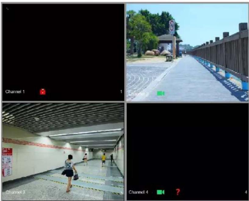
5.2.1 Live View Screen
You can view the live video from the connected cameras through each channel on the screen.
- By default, the system time, channel name and channel number are displayed on each channel window. This setting can be configured by selecting Main Menu > CAMERA > Overlay > Overlay.
- The figure in the bottom right corner represents channel number. If the channel position is changed or the channel name is modified, you can recognize the channel number by this figure and then perform the operations such as record query and playback.
Table 5-8 Live view description
| Icon Function | |
| Indicates recording status. This icon displays when the video is being recorded. | |
| This icon displays when the motion detection occurs in the scene. | |
| This icon displays when the video loss is detected. | |
| This icon displays when the channel monitoring is locked. |

To switch the position of two channels, point to one of the two channels, and then drag the window to the other channel.
5.2.2 Live View Control bar
The live view control bar provides you access to perform the operations such as playback, zoom, real-time backup, manual snapshot, voice talk, adding remote devices, and streams switch.
When you move the pointer to the top middle position of a channel window, the live view control bar is displayed.

If there is not operation for six seconds after the control bar is displayed, the control bar hides automatically.
Figure 5-38 Analog channel
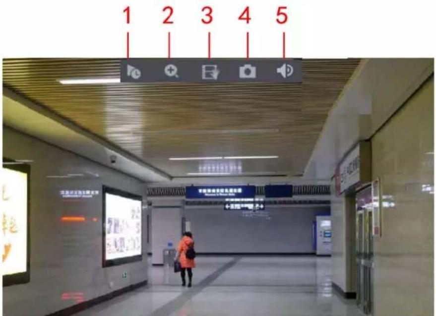
Figure 5-39 Digital channel
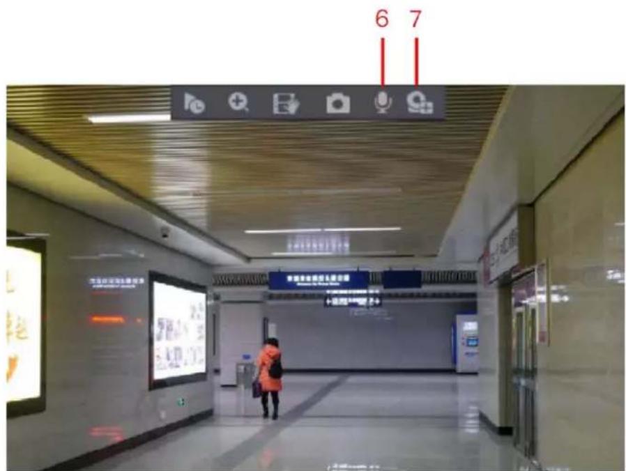
Figure 5-40 Control bar description
| No. | Function | No. | Function | No. | Function |
| 1 | Instant Playback | 4 | Manual Snapshot | 7 | Camera Registration |
| 2 Digital Zoom 5 Mute — | — | ||||
| 3 | Instant Record | 6 | Audio Talk | — | — |
5.2.2.1 Instant Playback
You can play back the previous 5 seconds to 60 minutes of the recorded video.
By clicking 📄, the instant playback page is displayed. The instant playback has the following features:
- Move the slider to choose the time you want to start playing.
• Play, pause and close playback. - The information such as channel name and recording status icon are shielded during instant playback and will not display until exited.
• During playback, screen split layout switch is not allowed. - To change the playback time, select Main Menu > SYSTEM > General > Basic, in the Instant Play box, enter the time you want to play back.
Figure 5-41 General
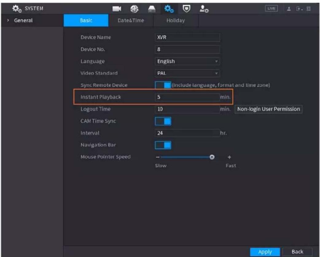
5.2.2.2 Digital Zoom
You can enlarge a specific area of the image to view the details by either of the following two ways.
- Click 📊, the icon switches to 🔒. Hold down the left mouse button to select the area you want to enlarge. The area is enlarged after the left mouse button is released.
- Point to the center that you want to enlarge, rotate the wheel button to enlarge the area.

- For some models, when the image is enlarged in the first way described previously, the selected area is zoomed proportionally according to the window.
- When the image is in the enlarged status, you can drag the image toward any direction to view the other enlarged areas.
- Right-click on the enlarged image to return the original status.
5.2.2.3 Instant Record
You can record the video of any channel and save the clip into a USB storage device.
By clicking 📄, the recording is started. To stop recording, click this icon again. The clip is automatically saved into the connected USB storage device.
5.2.2.4 Manual Snapshot
You can take one to five snapshots of the video and save into a USB storage device.
By clicking 📄, you can take snapshots. The snapshots are automatically saved into the connected USB storage device. You can view the snapshots on your PC.

To change the quantity of snapshots, select Main Menu > CAMERA > ENCODE > Snapshot, in the Manual Snap list, select the snapshot quantity.
5.2.2.5 Mute (Analog channel only)
You can mute the video sound by clicking 📄. This function is supported in single-channel view.
5.2.2.6 Warning Light (Supported on Camera with Warning Light Function)
Click to manually control the camera to turn on the warning light function.
5.2.2.7 Siren (Supported on Camera with Siren Function)
Click to manually control the camera to generate alarm sound.
5.2.2.8 Two-way Talk (Digital channel Only)
You can perform the voice interaction between the Device and the remote device to improve efficiency of emergency. This function is supported only when the remotely connected IPC device supports bidirectional talk.
- Click 📄, the icon switches to 📋, the bidirectional talk of the remote device is turned on. The bidirectional talk of other digital channels is disabled.
- Click to cancel the bidirectional talk. The bidirectional talk of other digital channels is resumed.
5.2.2.9 Adding Camera (Digital channel Only)
You can view the information of remote devices and add new remote devices to replace the current connected devices.
By clicking 📄, the Camera List page is displayed. For details about adding the remote devices, see "5.6 Configuring Remote Devices".
5.2.3 Navigation Bar
You can access the functions to perform operations through the function icons on the navigation bar. For example, you can access Main Menu and switch window split mode.

The navigation bar is disabled by default. It does not appear in the live view screen until it is enabled. To enable it, select Main Menu > SYSTEM > General > Basic, enable the Navigation Bar, and then click Apply.
Figure 5-42 Navigation bar

Table 5-9 Navigation bar description
| Icon Function | |
 | Open Main Menu. |
| [STXY] | Expand or condense the navigation bar. |
| [BKZ8] | Select view layout. |
 | Go to the previous screen. |
 | Go to the next screen. |
 | Enable tour function. The icon switches to [IMAGE] |
 | Open the PTZ control panel. For details, see "5.4 Controlling PTZ Cameras". |
 | Open the Image page.[IMAGE]This function is supported only in single-channel layout. |
| [2HZ7] | Open the record search page. For detail, see "5.9 Playing Back Video". |
 | Open the Alarm Status page to view the device alarm status. For details, see "5.21.3 Viewing Event Information". |
 | Open the CHANNEL INFO page to display the information of each channel. |
 | Open the Camera List page. For details, see "5.6.1 Adding Remote Devices". |
 | Open the Network page. For details, see "5.15.1 Configuring Network Settings". |
 | Open the Disk Manager page. For details, see "5.18.3 Configuring Disk Manager". |
 | Open the USB Management page. For details about USB operations, see "5.14.2 Backing up Files", "5.21.2 Viewing Log Information", "5.20.4 Exporting and Importing System Settings", "5.20.6 Updating the Device". |
5.2.4 Shortcut Menu
You can quickly access some function pages such as main menu, record search, PTZ setting, color setting and select the view split mode.
Right-click on the live view screen, the shortcut menu is displayed.

After you access any page through shortcut menu, you can return to the previous screen by right-clicking on the current screen.
Figure 5-43 Shortcut menu
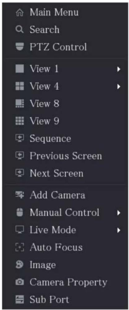
Table 5-10 Menu parameters
| Function Description | |
| Main Menu | Open Main Menu page. |
| Search | Open the PLAYBACK page where you can search and play back record files. |
| PTZ | Open the PTZ page. |
| View Layout | Configure the live view screen as a single-channel layout or multi-channel layout. |
| Previous Screen | Click Previous Screen to go to the previous screen. For example, if you are using 4-split mode, the first screen is displaying the channel 1-4, click Next screen, you can view channel 5-8. |
| Next Screen | |
| Add Camera | Open the Camera List page. For details, see "5.6 Configuring Remote Devices".This parameter displays on the right-click menu only after setting at least one channel to IP type in Main Menu > CAMERA > Channel Type. |
| Manual Control | Select Record Mode, you can configure the recording mode as Auto or Manual, or stop the recording. You can also enable or disable snapshot functionSelect Alarm Mode, you can configure alarm output settings. |
| Live Mode | Select General, the layout of live view screen is as default.Select Face, the detected face snapshots are displayed in the bottom of the live view screen. |
| Auto Focus | Point to the channel window and right-click on it to open the shortcut menu, and then click Auto Focus.Not all cameras support this function. |
| Image | Open the Image page where you can adjust the video image color. |
| Camera Property | Click to modify the camera properties. |
| Sub Port | Click to switch to extra screen control. |
5.2.5 AI Preview Mode
You can view the detected faces snapshots and comparison results of detected faces and the faces in the database, and play back the recorded picture file.
To display the AI preview mode, the face detection function must be enabled. For details, see "5.11.1.1 Face Detection".
Right-click on the live view screen to display the shortcut menu, and then select Live Mode > AI Mode, the AI preview mode page is displayed.
Figure 5-44 Live view
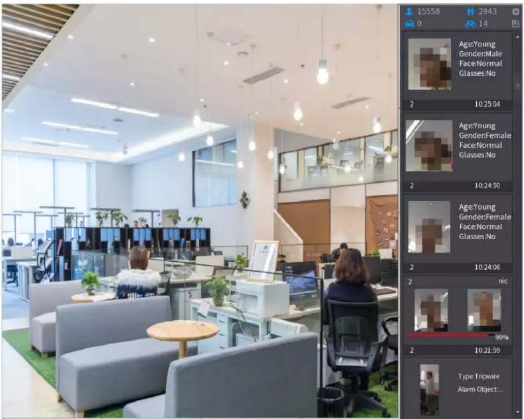
• 15558: Indicates the quantity of detected faces from 0 A.M. to midnight.
• 2943: Indicates the quantity of detected humans 0 A.M. to midnight.
• 0: Indicates the quantity of detected motor vehicles 0 A.M. to midnight.
• 14: Indicates the quantity of detected non-motor vehicles 0 A.M. to midnight.
- Click this icon and then select the face attributes that you want to display on the AI preview mode. Maximum four attributes are supported to display.
- Click this icon to export counting report in .csv format. The report information includes date, starting time, ending time, and the number of human, vehicle and face. The title of report is named as "device name_XVR_AI_Statistics_starting time_ending time.csv".
Figure 5-45 Properties
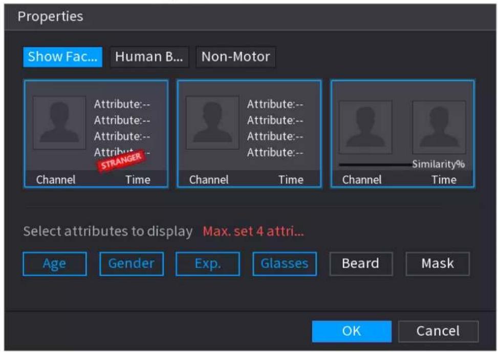
5.2.6 Channel Sequence
You can adjust the channel sequence displayed on live page on actual needs.

The live view page displays the default channel sequence after restoring factory defaults.
Step 1 Right-click on the live view page and select Sequence.

- The system displays the maximum number of window splits supported by the DVR after selecting Sequence.
- The Sequence page displays only the channel name and channel number of added
remote devices. ● represents the remote device is online, and ● represents the remote device is offline.
Figure 5-46 Sequence
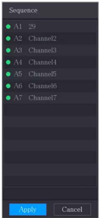
Step 2 Adjust channel sequence.
- Drag a channel to the target window split.
- Drag a window split to another to change the sequence.
You can view the channel sequence according to the channel number on the lower-right corner of the window split.
Figure 5-47 Adjusted sequence
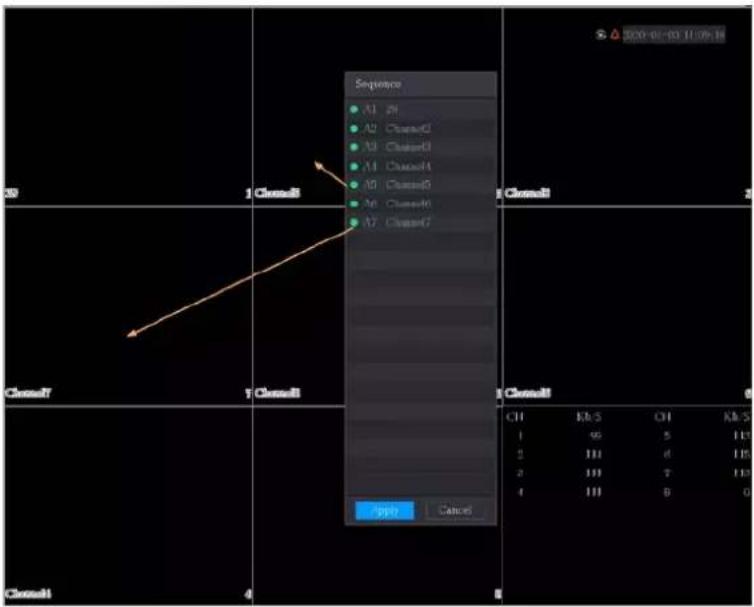
5.2.7 Color Setting
You can adjust the video image color effect such as sharpness, brightness, and contrast. The parameters are different according to the connected camera type. Take analog channel as an example.

Parameters displayed on the page vary from different cameras.
In the live view screen, right-click on the analog channel to see the shortcut menu, and then select Image, the Image page is displayed.
For details, see "5.5.1 Configuring Image Settings".
Figure 5-48 Image
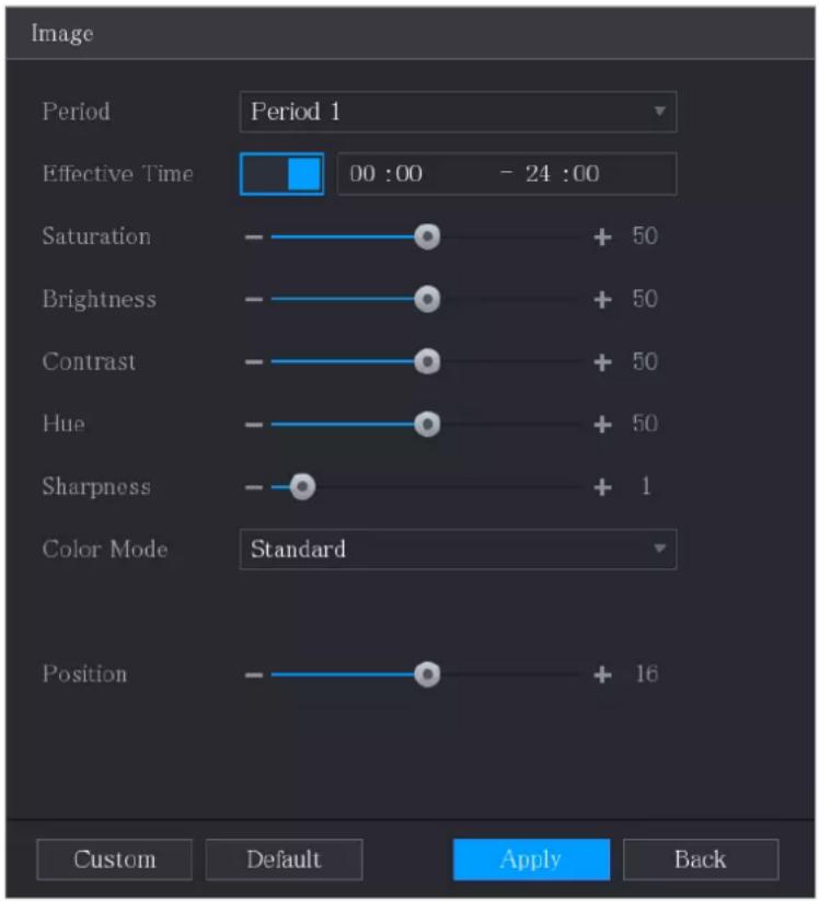
Table 5-11 Image settings
| Parameter Description | |
| Period | Divide 24 hours into two periods and configure the corresponding color settings. |
| Effective Time | Enable the function and then set the effective time for each period. |
| Sharpness | Adjust the sharpness of image edge. The bigger the value is, the more obvious the image edge, and the noise is also greater.The value ranges from 1 to 15. The default value is 1. |
| Hue | Adjust the hue of image. The value ranges from 0 to 100. The default value is 50. |
| Brightness | Adjust the image brightness. The value ranges from 0 to 100. The default value is 50.The bigger the value is, the brighter the image will become. You can adjust this value when the image as a whole looks dark or bright.However, the image is likely to become dim if the value is too big.The recommended range is between 40 and 60. |
| Contrast | Adjust the image contrast. The bigger the value is, the more obvious the contrast between the light area and dark area will become. You can adjust this value when the contrast is not obvious. However, if the value is too big, the dark area is likely to become darker and the light area over exposed. If the value is too small, the image is likely to become dim.The value ranges from 0 to 100. The default value is 50. The recommended range is between 40 and 60. |
| Saturation | Adjust the color shades. The bigger the value, the lighter the color will become. This value does not influence the general image lightness.The value ranges from 0 to 100. The default value is 50. The recommended range is between 40 and 60. |
| Color Mode | In the Color Mode list, you can select Standard, Soft, Bright, Vivid,Bank, Customized 1, Customized 2, Customized 3, and Customized 4.The sharpness, hue, brightness, contrast and saturation will adjust automatically according to the selected color mode. |
| EQ | Enhance the image effect. Adjust the effect value.Clickimage is adjusted to the optimized effect automatically.Clickthe current effect setting will be locked.Only HD analog channel supports this function. |
| Position | Adjust the display position of the image in the channel window. The value indicates pixel. The default value is 16.This function is only supported by analog channel. |
| Custom | You can customize four color modes.Click Custom. The Custom Color page is displayed.In the Color Mode list, select Custom 1, for example. Then configure the settings for sharpness, hue, brightness, contrast and saturation. If you select All, the configuration will apply to all four customized color modes.Click OK.On the Image page, in the Color Mode list, you can select the customized color mode. |
5.2.8 Live View Display
5.2.8.1 Configuring Display Settings
You can configure the display effect such as displaying time title and channel title, adjusting image transparency, and selecting the resolution.
Step 1 Select Main Menu > DISPLAY > Display.
Figure 5-49 Display
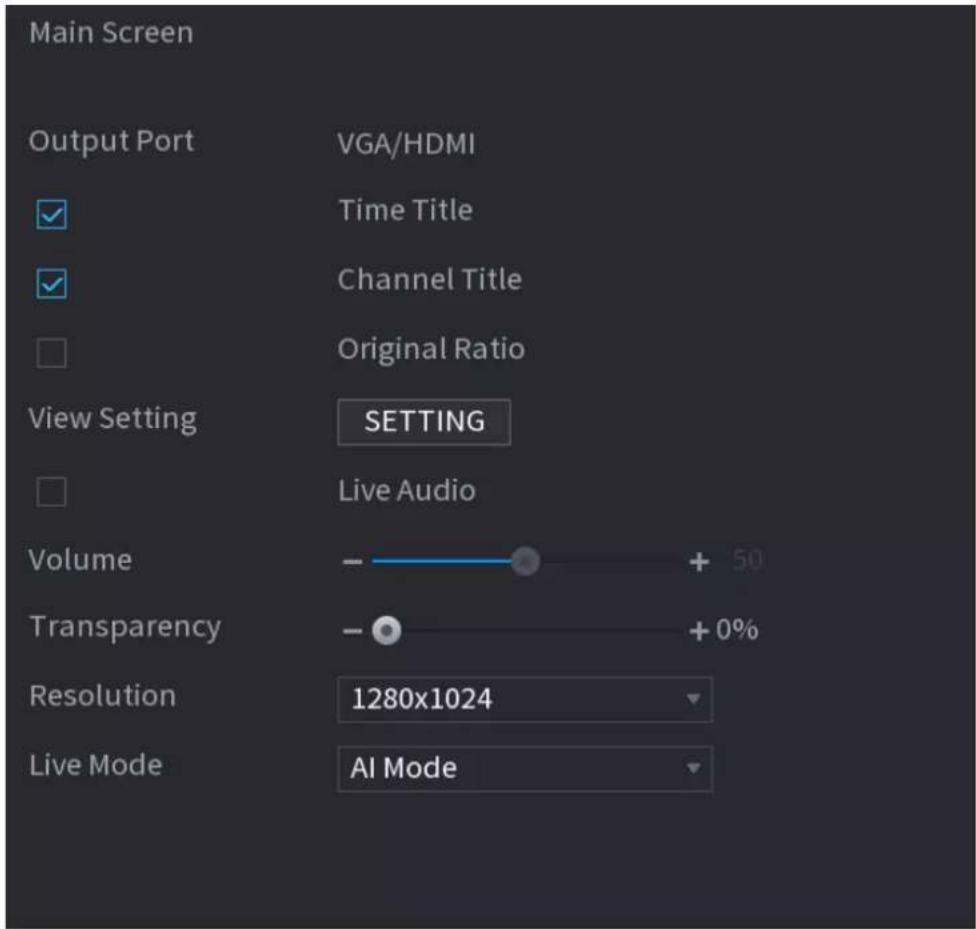
Step 2 Configure the settings for the display parameters.
Table 5-12 Display parameters
| Parameter Description | ||
| Main Screen | Output Port | Indicates the main screen port. |
| Time Title | Select the Time Title checkbox, the current system time displays in each channel window in live view screen. To hide the time, clear the checkbox. | |
| Channel Title | Select the Channel Title checkbox, the channel name, channel number and recording status display in each channel window in live view screen. To hide the time, clear the checkbox. | |
| Original Ratio | Select the Original Ratio checkbox, the video image displays in its actual size in the channel window. | |
| View Setting | Click SETTING to enable AI rule, bounding box of IVS target and SMD rule on the live page. | |
| Live Audio | Select the Live Audio checkbox to enable the audio adjustment function in the channel window on the live view screen.Move the slider to adjust the volume of live audio. | |
| Volume | ||
| Transparency | Configure the transparency of the graphical user interface (GUI). The higher the value, the more transparent the GUI becomes. | |
| Resolution | Select resolution for the video. The default resolution for VGA port and HDMI port is 1280 × 1024.Some of the resolution options might not be supported on the HDMI port. | |
| Live Mode | General: No information is displayed on the channel window.AI Mode: Displays the detected face snapshots.This function is available on select models. | |
| Sub Screen | Enable | Enable extra screen function. After this function is enabled, you can select which port as extra screen port, and the other port automatically becomes the main screen port. |
| Output Port | Select the VGA port or HDMI port as the port connected by a secondary monitor. For example, if you select HDMI port as the extra screen port, the VGA port automatically becomes the main screen port. | |
| Resolution | Select resolution for the video. The default resolution for VGA port and HDMI port is 1280 × 720.Some of the resolution options might not be supported on the HDMI port. | |
| Show Message | After it is enabled, the sub screen will display alarm message when an alarm is triggered. | |
| The main menu does not display on the extra screen.If you do not enable the extra screen function, both the VGA port and HDMI port display the same image. | ||
5.2.8.2 Configuring Zero-Channel Settings
You can view several video sources on one channel on the web end.
Step 1 Select Main Menu > DISPLAY > Zero-Channel.
Figure 5-50 Zero-channel
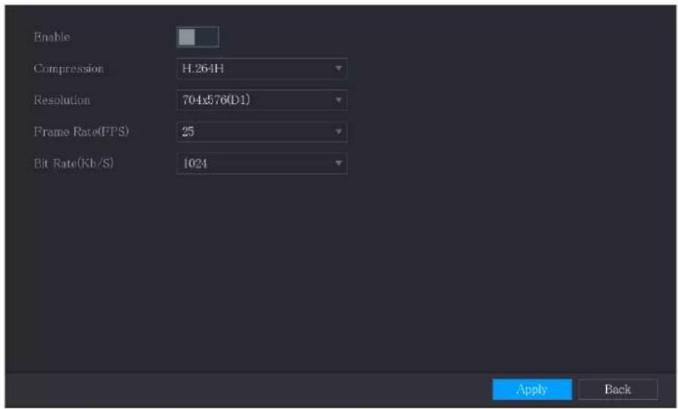
Step 2 Configure the settings for the zero-channel parameters.
Table 5-13 Zero-channel parameters
| Parameter Description | |
| Enable | Enable zero-channel function. |
| Compression | In the Compression list, select the video compression standard according to the device capability. The default is H.265. |
| Resolution | In the Resolution list, select the video resolution. The default is 704 × 576 (D1). |
| Frame Rate (FPS) | Select a value between 1 and 25 for PAL standard, and between 1 and 30 for NTSC standard. The actual arrange is decided and selected dependent on the Device capability. |
| Bit Rate (Kb/S) | The default value is 1024Kb/S. The actual arrange is decided and selected dependent on the Device capability and frame rate. |
Step 3 Click Apply to save the settings.
In the live page on the web, click ☐ to select one of the multi-channel modes, and then you can view the local video image.
5.2.8.3 Configuring TV

This function is available on select models.
You can adjust the border margins in top, bottom, left and right directions as well as the brightness of the monitor connected to the Video out port of the Device.
Step 1 Select Main Menu > DISPLAY > TV Adjust.
Figure 5-51 TV adjust
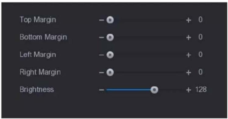
Step 2 Configure the parameters according to your actual situation.
Step 3 Click Apply to complete the settings.
5.2.9 Configuring Tour Settings
You can configure a tour of selected channels to repeat playing videos. The videos display in turn according to the channel group configured in tour settings. The system displays one channel group for a certain period and then automatically changes to the next channel group.
Step 1 Select Main Menu > DISPLAY > Tour Setting.
Figure 5-52 Main screen
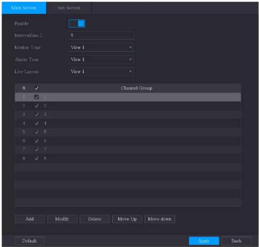
Figure 5-53 Sub screen
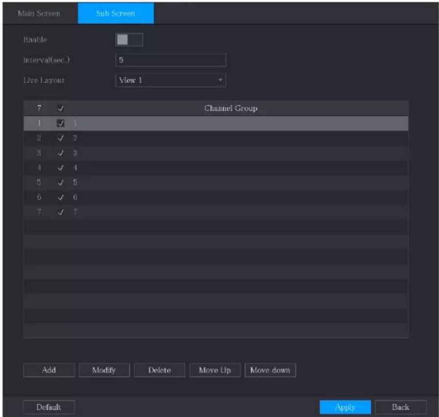
Step 2 Configure the settings for the tour parameters for both Main Screen and Sub Screen.
Figure 5-54 Tour parameters
| Parameter Description | |
| Enable | Enable tour function. |
| Interval (Sec.) | Enter the amount of time that you want each channel group displays on the screen. The value ranges from 5 seconds to 120 seconds, and the default value is 5 seconds. |
| Motion Tour, Alarm Tour | Select the View 1 or View 8 for Motion Tour and Alarm Tour (system alarm events). |
| Live Layout | In the Live Layout list, select View 1, View 4, View 8, or other modes that are supported by the Device. |
| Channel Group | Display all channel groups under the current Window Split setting.Add a channel group: Click Add, in the pop-up Add Group channel, select the channels to form a group, and then click Save.Delete a channel group: Select the checkbox of any channel group, and then click Delete.Edit a channel group: Select the checkbox of any channel group and then click Modify, or double-click on the group. The Modify Channel Group dialog box is displayed. You can regroup the channels.Click Move up or Move down to adjust the position of channel group. |
Step 3 Click Apply to save the settings.

- On the upper-right corner of the live view screen, use the left mouse button or press Shift to switch between (image switching is allowed) and (image switching is not allowed) to turn on/off the tour function.
- On the navigation bar, click 📋 to enable the tour and click 📋 to disable it.
Adding a Channel Group
Step 1 Click Add.
Figure 5-55 Add group
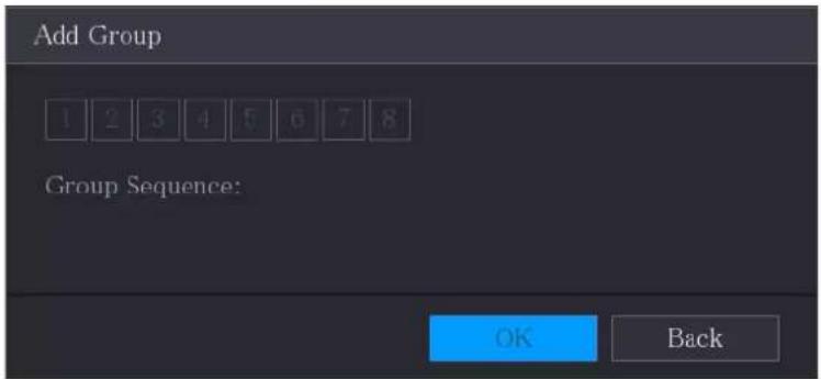
Step 2 Select the channels that you want to group for tour.

If you want to select more than one channel, in the Live Layout list, do not select View 1.
Figure 5-56 Add view
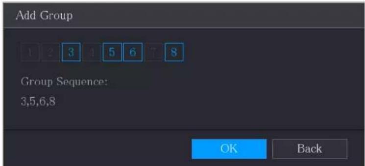
Step 3 Click OK to complete the settings.
Modifying a Channel Group
Double-click on a channel group, the Channel Group Modified page is displayed.
You can modify channel group and click OK to complete the settings.
Figure 5-57 Group modified
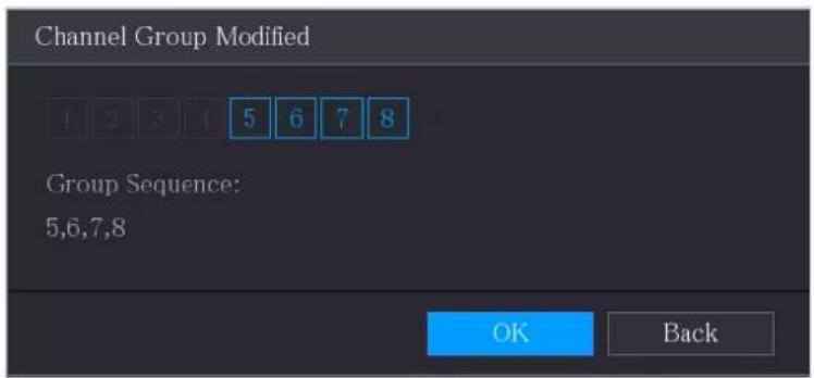
5.2.10 Quick Operation Bar
You can quickly access to the function modules on function tiles and setting menu through shortcut icons on quick operation bar.
This topic uses ALARM and CAMERA an examples to show you how to quickly access to other modules.
Shortcut Icons on Function Titles
Click ALARM to enter the ALARM page.
Figure 5-58 Alarm
![Alarm Info Alarm Status Alarm-in Port Alarm-out Port Video Detection Exception Disarming Type All Start Time 2020 -03 -01 00 :00 :00 End Time 2020 -03 -02 00 :00 :00 Search 55 Time Type Play 41 2020-03-01 20:17:40 42 2020-03-01 20:17:40 43 2020-03-01 20:17:40 44 2020-03-01 20:17:40 45 2020-03-01 20:17:40 46 2020-03-01 20:17:40 No Disk 47 2020-03-01 20:17:40 48 2020-03-01 20:17:40 49 2020-03-01 20:17:40 50 2020-03-01 20:17:41 51 2020-03-01 20:17:41 52 2020-03-01 20:17:41 53 2020-03-01 20:17:41 54 2020-03-01 20:17:41 55 2020-03-01 20:17:41 < 1/1 > [HOME] Backup Details](/content/2026/05/1061593/images/58f693faaba18c652603a12a17f2b07bf1f41ef5ab977992363b504185a10ede.jpg)
Table 5-14 Alarm parameters
| Icon | Description |
 | Click to go to SEARCH page. |
 | Click to go to ALARM page. |
 | Click to go to AI page. |
 | Click to go to POS page. |
 | Click to go to NETWORK page. |
 | Click to go to MAINTAIN page. |
 | Click to go to BACKUP page. |
 | Click to go to DISPLAY page. |
 | Click to go to AUDIO page. |
Shortcut Icons on Setting Menu
Click CAMERA to enter the CAMERA page.
Figure 5-59 Camera
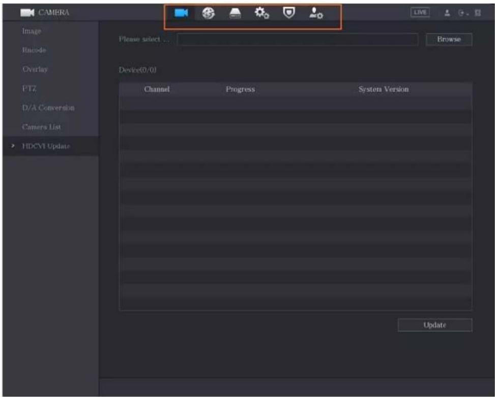
Table 5-15 Camera parameters
| Icon | Description |
 | Click to go to CAMERA page. |
 | Click to go to NETWORK page. |
 | Click to go to STORAGE page. |
 | Click to go to SYSTEM page. |
 | Click to go to SECURITY page. |
 | Click to go to ACCOUNT page. |
5.3 Entering Main Menu
Right-click on the live view screen, and then the shortcut menu is displayed. Click Main Menu and then log in to the system.
Figure 5-60 Main menu
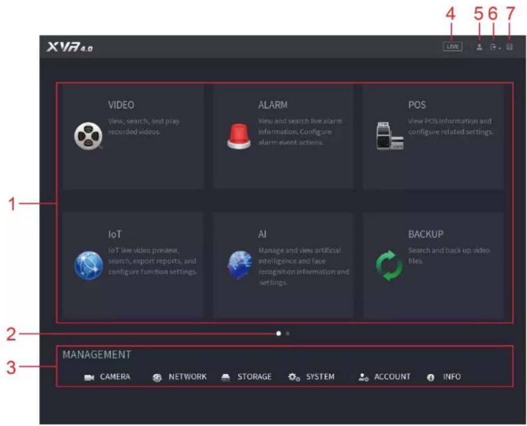
Table 5-16 Main menu description
| No. Icon | Description | |
| 1 | Function tiles | Includes nine function tiles:SEARCH, ALARM, SMART DETECTION, POS, IoT, MAINTAIN, BACKUP, DISPLAY and AUDIO. Click each tile to open the configuration page of the tile.SEARCH : Search for and play back the recorded video saved on the Device.ALARM: Search for alarm information and configure alarm event actions.SMART DETECTION: Search SMD, face detection, and IVS information, and configure related settings.POS: You can connect the Device to the POS (Point of Sale) machine and receive the information from it.IoT: IoT live video preview, search, export reports, and configure function settings.MAINTAIN: You can view log and system information, test network and do other maintenance work.BACKUP: Search and back up the video files to the external storage device such as USB storage device.DISPLAY: Configure the display effect such as displaying content, image transparency, and resolution, and enable the zero-channel function.AUDIO : Manage audio files and configure the playing schedule. The audio file can be played in response to an alarm event if the voice prompts function is enabled. |
| 2 | Switch icon | indicates the current page of main menu. Clickto switch to the next page or clickorto turn page. |
| 3 | Setting menu | Includes six configurations through which you can configure camera settings, network settings, storage settings, system settings, account settings, and view information. |
| 4 | Live | Clickto go to the live view screen. |
| 5 |  | When you point to, the current user account is displayed. |
| 6 | Click , select Logout, Reboot, or Shutdown according to your actual situation. , select Logout, Reboot, or Shutdown according to your actual situation. | |
| 7 | Displays Cell Phone Client and Device SN QR Code.Cell Phone Client: Use your mobile phone to scan the QR code to add the device into the Cell Phone Client, and then you can start accessing the Device from your cell phone.Device SN: Obtain the Device SN by scanning the QR code. Go to the P2P management platform and add the Device SN into the platform. Then you can access and manage the device in the WAN. For details, refer to the P2P operation manual. You can also configure P2P function in the local configurations. See "5.1.4.5 Configuring P2P Settings". | |
5.4 Controlling PTZ Cameras
PTZ is a mechanical platform that carries a camera and a protective cover and performs overall control remotely. A PTZ can move in both horizontal and vertical direction to provide all-around view to the camera.

Before operating PTZ, ensure the network connection between PTZ and the Device.
5.4.1 Configuring PTZ Connection Settings
You need to configure the PTZ connection settings before use.
- Local connection: RS-485 Port for connecting speed dome or coaxial cable for connecting coaxial camera.
- Remote connection: local area network.
Step 1 Select Main Menu > CAMERA > PTZ.
Figure 5-61 PTZ
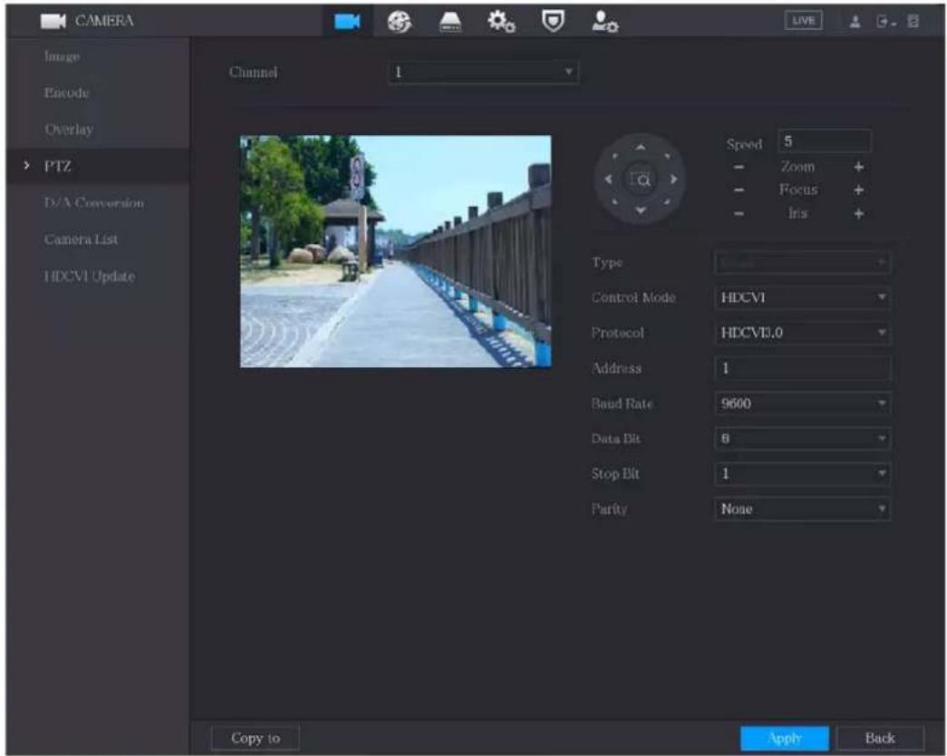
Step 2 Configure the settings for the PTZ connection parameters.
Table 5-17 PTZ connection parameters
| Parameter Description | |
| Channel | In the Channel list, select the channel that you want to connect the PTZ camera to. |
| Type | ● Local: Connect through RS-485 port or coaxial cable. |
| Parameter Description | |
| ● Remote: Connect through network by adding IP address of PTZ camera to the Device. | |
| Control Mode | In the Control Mode list, select Serial Port or HDCVI. For HDCVI series product, select HDCVI. The control signal is sent to the PTZ through the coaxial cable. For the serial mode, the control signal is sent to the PTZ through the RS-485 port. |
| Protocol | In the Protocol list, select the protocol for the PTZ camera. For example, select HDCVI3.0. |
| Address | In the Address box, enter the address for PTZ camera. The default is 1.The entered address must be the same with the address configured on the PTZ camera; otherwise the PTZ camera cannot be controlled from the Device. |
| Baud Rate | In the Baud Rate list, select the baud rate for the PTZ camera. The default is 9600. |
| Data Bits The default value is 8. | |
| Stop Bits The default value is 1. | |
| Parity The default value is NONE. | |
Step 3 Click Apply to save the settings.

Click Copy to copy the settings to other channels.
5.4.2 Working with PTZ Control Panel
PTZ control panel performs the operations such as directing camera in eight directions, adjusting zoom, focus and iris settings, and quick positioning.
Basic PTZ Control Panel
Right-click on the live view screen and then select PTZ. The PTZ control panel is displayed.
Figure 5-62 PTZ control panel
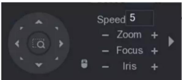

The functions with buttons in gray are not supported by the system.
Table 5-18 PTZ control panel description
| Parameter Description | |
| Speed | Controls the movement speed. The bigger the value is, the faster the movement will be. |
| Zoom | Zoom out.Zoom in. |
| Focus | Focus far.Focus near. |
| Iris | Image darker.Image brighter. |
| PTZ movement | Supports eight directions. |
 | Fast positioning button.Positioning: Click to enter the fast positioning screen, and then click anywhere on the live view screen, the PTZ will turn to this point and move it to the middle of the screen.Zooming: On the fast positioning screen, drag to draw a square on the view. The square supports zooming.Dragging upward is to zoom out, and dragging downward is to zoom in.The smaller the square, the larger the zoom effect.This function is available on select models and can only be controlled through mouse operations. |
 | Click you can control the four directions (left, right, up, and down) PTZ movement through mouse operation. |
 | Click to open the expanded PTZ control panel. |
Expanded PTZ Control Panel
On the basic PTZ control panel, click ▶ to open the expanded PTZ control panel to find more options.
Figure 5-63 Expanded PTZ control panel
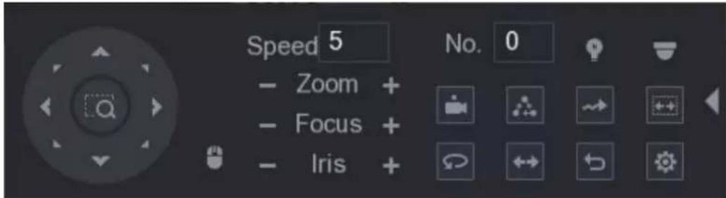

- The functions with buttons in gray are not supported by the system.
- Right-click once to return to the page of PTZ basic control panel.
Figure 5-64 Expanded PTZ control panel description
| Icon | Function | Icon | Function | |
 | Preset |  | Pan | |
 | Tour |  | Flip | |
 | Pattern |  | Reset | |
 | Scan |  | Click theAuxiliary Configicon to open the PTZ functions settings page. | |
 | Auxiliary |  | Click theEnter Menuicon to open theMENU OPERATIONpage. | |
5.4.3 Configuring PTZ Functions
5.4.3.1 Configuring Presets
Step 1 On the expanded PTZ control panel, click

Figure 5-65 Preset
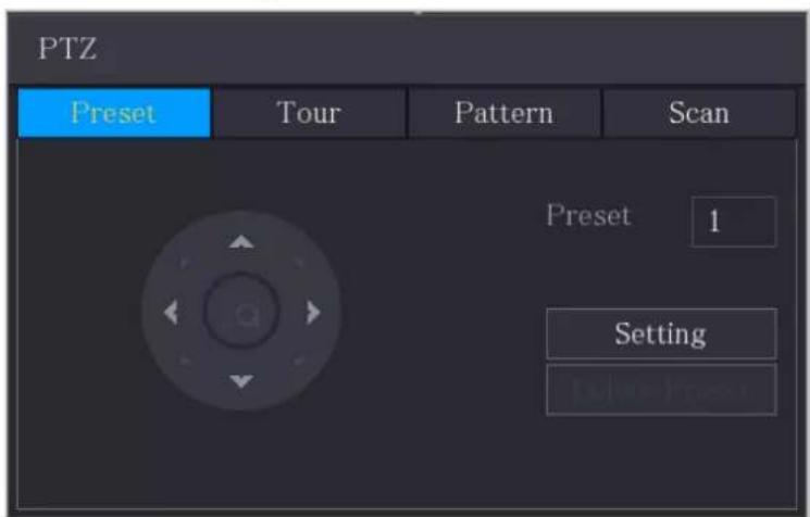
Step 2 Click the direction arrows to the required position.
Step 3 In the Preset box, enter the value to represent the required position.
Step 4 Click Setting to complete the preset settings.
5.4.3.2 Configuring Tours
Step 1 On the expanded PTZ control panel, click
Step 2 Click the Tour tab.
Figure 5-66 Tour
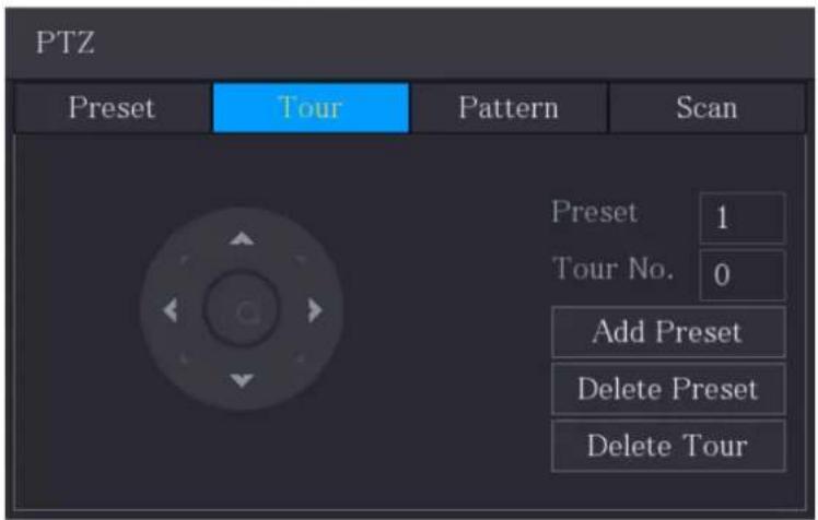
Step 3 In the Tour No. box, enter the value for the tour route.
Step 4 In the Preset box, enter the preset value.
Step 5 Click Add Preset.
A preset will be added for this tour.

• You can repeat adding more presets.
- Click Delete Preset to delete the preset for this tour. This operation can be repeated to delete more presets. Some protocols do not support deleting.
5.4.3.3 Configuring Patterns
Step 1 On the expanded PTZ control panel, click
Step 2 Click the Pattern tab.
Figure 5-67 Pattern
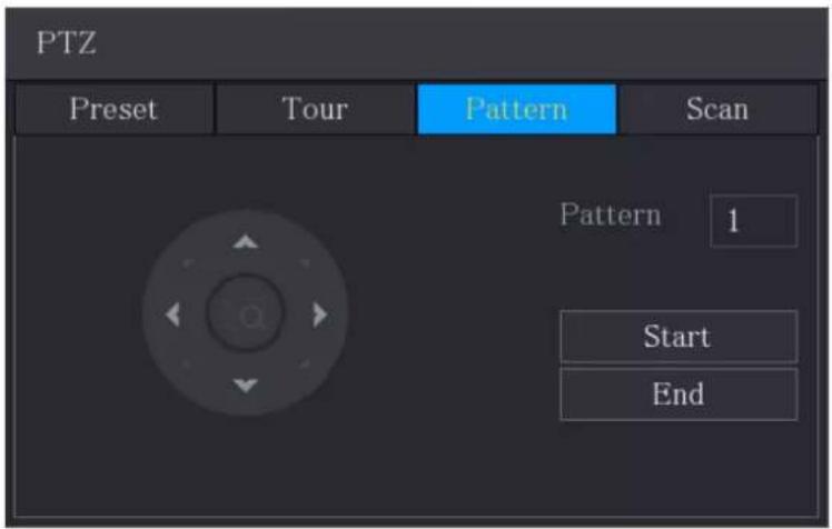
Step 3 In the Pattern box, enter the value for pattern.
Step 4 Click Start to perform the directions operations. You can also go to the PTZ Control Panel to perform the operations of adjusting zoom, focus, iris, and directions.
Step 5 On the PTZ page, click End to complete the settings.
5.4.3.4 Configuring Scan
Step 1 On the expanded PTZ control panel, click
Step 2 Click the Scan tab.
Figure 5-68 Scan
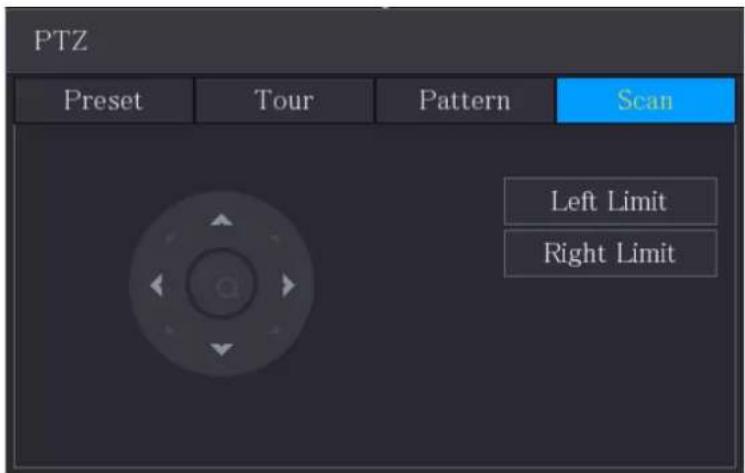
Step 3 Click the direction arrows to position the left and right limits.
5.4.4 Calling PTZ Functions
After you have configured the PTZ settings, you can call the PTZ functions for monitoring from the expanded PTZ control panel.
Figure 5-69 Expanded PTZ control panel
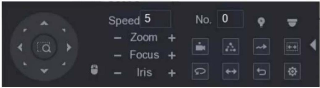
5.4.4.1 Calling Presets
Step 1 On the expanded PTZ Control Panel, in the No. box, enter the value of the preset that you want to call.
Step 2 Click to call the preset.
Step 3 Click again to stop calling the preset.
5.4.4.2 Calling Tours
Step 1 On the expanded PTZ control panel, in the No. box, enter the value of the tour that you want to call.
Step 2 Click to call the tour.
Step 3 Click again to stop calling the tour.
5.4.4.3 Calling Patterns
Step 1 On the expanded PTZ control panel, in the No. box, enter the value of the pattern that you want to call.
Step 2 Call to call the pattern.
The PTZ camera moves according to the configured pattern repeatedly.
Step 3 Click again to stop calling the pattern.
5.4.4.4 Calling AutoScan
Step 1 On the expanded PTZ control panel, in the No. box, enter the value of the border that you want to call.
Step 2 Click.
The PTZ camera performs scanning according to the configured borders.
Step 3 Click again to stop auto scanning.
5.4.4.5 Calling AutoPan
Step 1 On the expanded PTZ control panel, click 📋 to start moving in horizontal direction.
Step 2 Click again to stop moving.
5.4.4.6 Using AUX Button
On the expanded PTZ control panel, click 🔒, the AUX setting page is displayed.
- In the Shortcut Aux list, select the option that corresponds to the applied protocol.
- In the Aux No. box, enter the number that corresponds to the AUX switch on the decoder.
Figure 5-70 Auxiliary
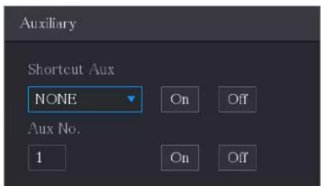
5.4.5 Calling OSD Menu
For the coaxial camera, you can call the OSD menu through the expanded PTZ control panel.
Step 1 On the expanded PTZ control panel, click 📋.
Figure 5-71 PTZ menu
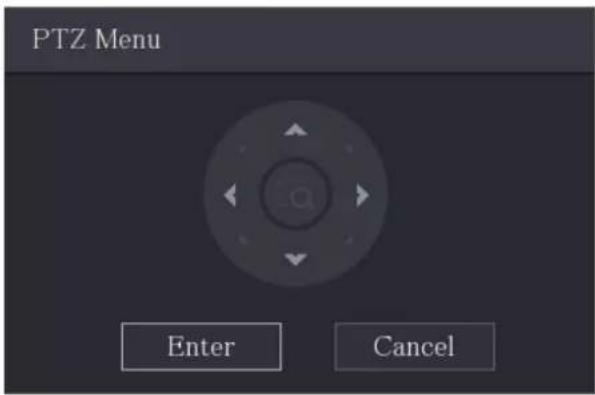
Step 2 Click Enter.
Figure 5-72 OSD
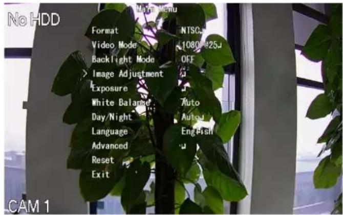
Step 3 On the PTZ Menu page, click the arrow button to select the onscreen parameters.
Step 4 Click Enter to complete the settings.
5.5 Configuring Camera Settings
5.5.1 Configuring Image Settings
You can configure the image settings such as saturation, contrast, brightness, sharpness for each connected camera.
Step 1 Select Main Menu > CAMERA > Image.
Figure 5-73 Analog channel
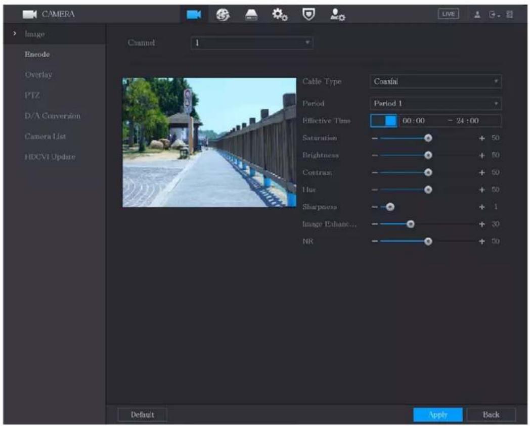
Figure 5-74 Digital channel
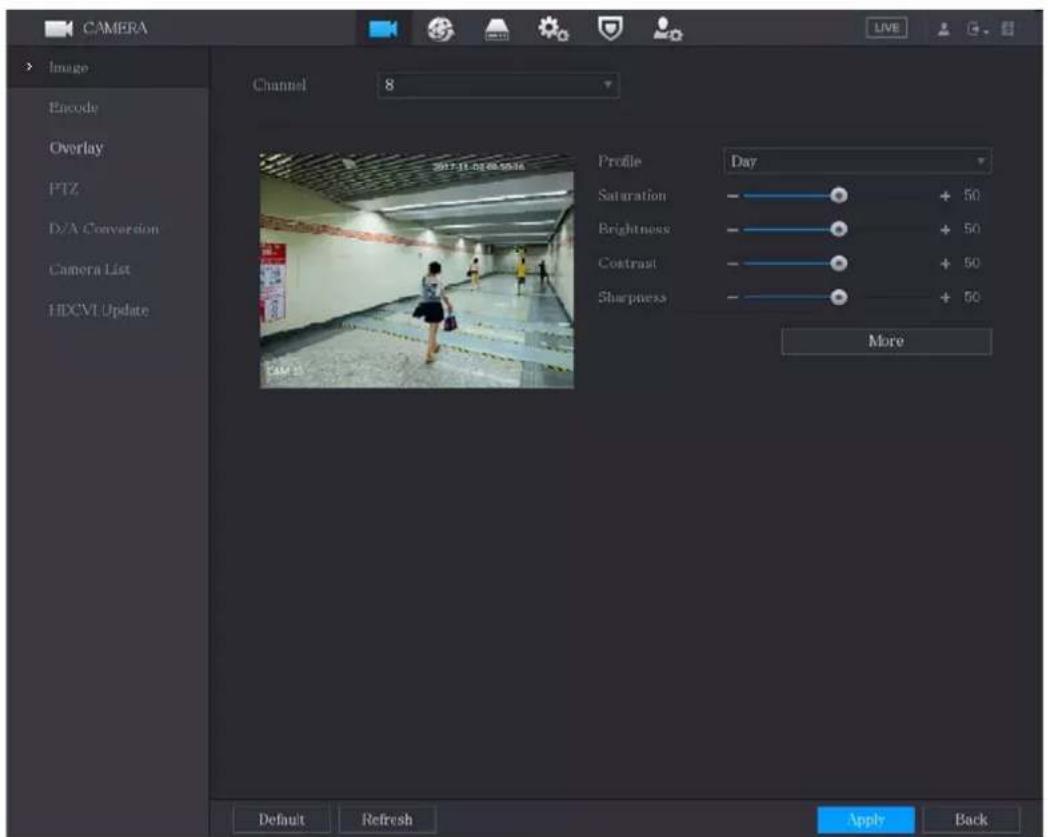
Step 2 Configure the settings for the image parameters.
On the digital channel page, click More to display more parameters.
Table 5-19 Image parameters
| Parameter Description | |
| Channel | In the Channel list, select the channel that you want to configure. |
| Cable Type | In the Cable Type list, select the cable type that the camera uses.This function is available on select models. |
| Period | In the Period list, select a time period for the image settings. The image settings will be only used during the selected period. |
| Effective Time | Enable the effective function.In the Effective Time box, enter the start time and end time for the period you selected. |
| Saturation | Adjusts the color shades. The bigger the value, the lighter the color will become. This value does not influence the general image lightness.The value ranges from 0 to 100. The default value is 50. The recommended range is between 40 and 60. |
| Contrast | Adjusts the image contrast. The bigger the value is, the more obvious the contrast between the light area and dark area will become. You can adjust this value when the contrast is not obvious. However, if the value is too big, the dark area is likely to become darker and the light area over exposed. If the value is too small, the image is likely to become dim.The value ranges from 0 to 100. The default value is 50. The recommended range is between 40 and 60. |
| Brightness | Adjusts the image brightness. The bigger the value is, the brighter the image will become. You can adjust this value when the image as a whole looks dark or bright. However, the image is likely to become dim if the value is too big.The value ranges from 0 to 100. The default value is 50. The recommended range is between 40 and 60. |
| Hue | Adjusts the hue of image. The value ranges from 0 to 100. The default value is 50. |
| Sharpness | Adjusts the sharpness of image edge. The bigger the value is, the more obvious the image edge, and the noise is also greater.The value ranges from 1 to 15. The default value is 1. |
| Image Enhance | Adjusts the image definition. The bigger the value is, the clearer the image will become, but there will be more noises. |
| NR | Reduces the noises from image. The bigger the value is, the better the image will become. |
| Config File | In the Config File list, select Day, Night, Normal, or Switch By Period. The system configures the parameters correspondingly.Day: Apply the configuration during daytime.Night: Apply the configuration during nighttime.Normal: Apply the configuration during day and night.Switch by Period: If you select this option, you need to configure the sunrise time and sunset time where you are located. |
| Mirror | Enable the function, the left and right side of the video image will be switched. It is disabled by default. |
| 3D Denoise | This function specially applies to the image which frame rate is configured as 2 at least. It reduces the noises by making use of the information between two frames. The bigger the value is, the better the effect. |
| Flip | In the Flip list, you can select 180^ to change the video image display.By default, the setting is No Flip. |
| Light | In the Light list, select Close or Enable to use the backlight compensation or not. |
| Scene Mode | Configure the white balance to adjust the general hue of the image. The default setting is Auto.Auto: Automatically apply white balance to different colors to make the image color display normally.Sunny: Apply the threshold value to sunny environment.Night: Apply the threshold value to night.Customized: Manually adjust the Red Gain and Blue Gain values. |
| Day & Night | Configure the color and black&white mode of the image. This setting is not affected by the configuration files. The default setting is Auto.Color: The camera outputs color image only.Auto: Depends on the camera, such as overall brightness and whether there is an IR light, either color image or black&white image is output.B/W: The camera outputs Black and white image only.By Time: The camera outputs image according to the configured sunrise time and sunset time. |
Step 3 Click Apply to complete the settings.
5.5.2 Configuring Encode Settings
Step 1 Select Main Menu > CAMERA > Encode > Audio/Video.
Figure 5-75 Audio/video
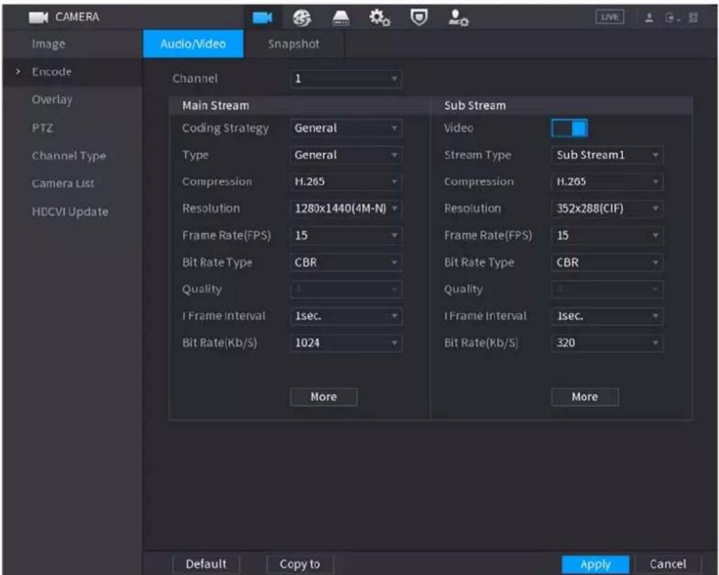
Step 2 Configure the settings for the main/sub streams parameters.
Table 5-20 Main/sub stream parameters
| Parameter Description | |
| Channel | In the Channel list, select the channel that you want to configure the settings for. |
| Coding Strategy | General: Uses general coding strategy.Smart Codec: Enables the smart codec function. This function can reduce the video bit stream for non-important recorded video to maximize the storage space.Al Codec: Enables the AI codec function. This function can reduce the video bit stream for non-important recorded video to maximize the storage space. |
| Type | Main Stream: In the Type list, select General, Motion, or Alarm.Sub Stream: This setting is not configurable. |
| Compression | In the Compression list, select the encode mode.H.265: Main profile encoding. This setting is recommended.H.264H: High profile encoding. Low bit stream with high definition.H.264: General profile encoding.H.264B: Baseline profile encoding. This setting requires higher bit stream compared with other settings for the same definition. |
| Resolution | In the Resolution list, select resolution for the video.The maximum video resolution might be different dependent on your device model. |
| Frame Rate (FPS) | Configure the frames per second for the video. The higher the value, the clearer and smoother the image will become. Frame rate changes along with the resolution.Generally, in PAL format, you can select the value from 1 through 25; in NTSC format, you can select the value from 1 through 30. However, the specific range of frame rate that you can select depends on the capability of the Device. |
| Quality | This function is available if you select VBR in the Bit Rate List.The higher the value, the better the image will become. |
| I Frame Interval | The interval between two reference frames. |
| Bit Rate (Kb/S) | In the Bit Rate list, select a value or enter a customized value to change the image quality. The bigger the value is, the better the image will become. |
| Video | Enable the function for sub stream. |
| Audio | Click More, the More page is displayed.• Audio: This function is enabled by default for main stream. You need to manually enable it for sub stream 1. Once this function is enabled, the recorded video file is composite audio and video stream.• Audio Source: In the Audio Source list, you can select LOCAL and HDCVI.◇ LOCAL: The audio signal is input from Audio input port.◇ HDCVI: The audio signal is input from HDCVI camera.• Audio Format: In the Compression list, select a format that you need. |
| Audio Source | |
| Compression |
Step 3 Click Apply to complete the settings.

Click Copy to copy the settings to other channels.
5.5.3 Configuring Snapshot Settings
Step 1 Select Main Menu > CAMERA > Encode > Snapshot.
Figure 5-76 Snapshot
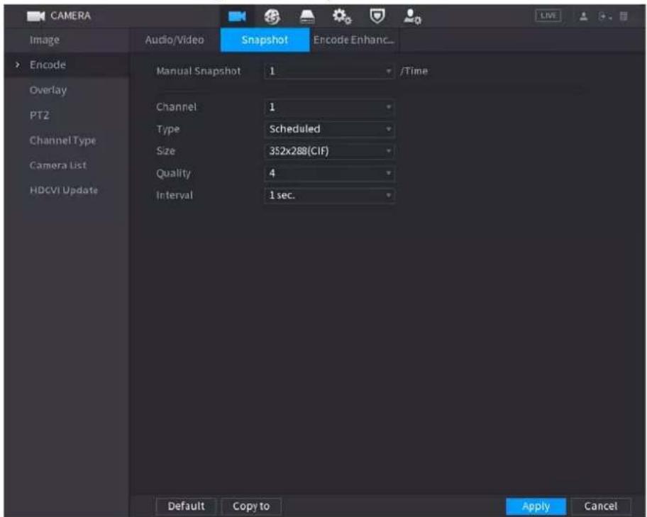
Step 2 Configure the settings for the snapshot parameters.
Table 5-21 Snapshot parameters
| Parameter Description | |
| Manual Snapshot | In the Manual Snapshot list, select how many snapshots you want to take each time. |
| Channel | In the Channel list, select the channel that you want to configure the settings for. |
| Type | In the Type list, you can select Scheduled, Event, or Face Snapshot as the event type for which you want to take a snapshot.Scheduled: The snapshot is taken during the scheduled period.Event: The snapshot is taken when there is an alarm event occurs, such as motion detection event, video loss, and local alarms.Face Snapshot: The snapshot is taken when the face is detected. The face detection function is support only with the Channel 1. |
| Size | In the Size list, select a value for the image. The bigger the value is, the better the image will become. |
| Quality | Configures the image quality by 6 levels. The higher the level, the better the image will become. |
| Interval | Configures or customizes the snapshot frequency. You can select 1 second per one snapshot to 7 seconds per one snapshot. The maximum is 3600 seconds per one snapshot. |
Step 3 Click Apply to complete the settings.

Click Copy to to copy the settings to other channels.
5.5.4 Configuring Encode Enhancement
You can enable this function and get more FPS in encode settings (see "5.5.2 Configuring Encode Settings"). In the meantime, you will not be able to use extra screen function (see "5.2.8.1 Configuring Display Settings") and AI functions (see "5.11 AI Function").
Select Main Menu > CAMERA > Encode > Encode Enhancement.
Figure 5-77 Encode enhancement
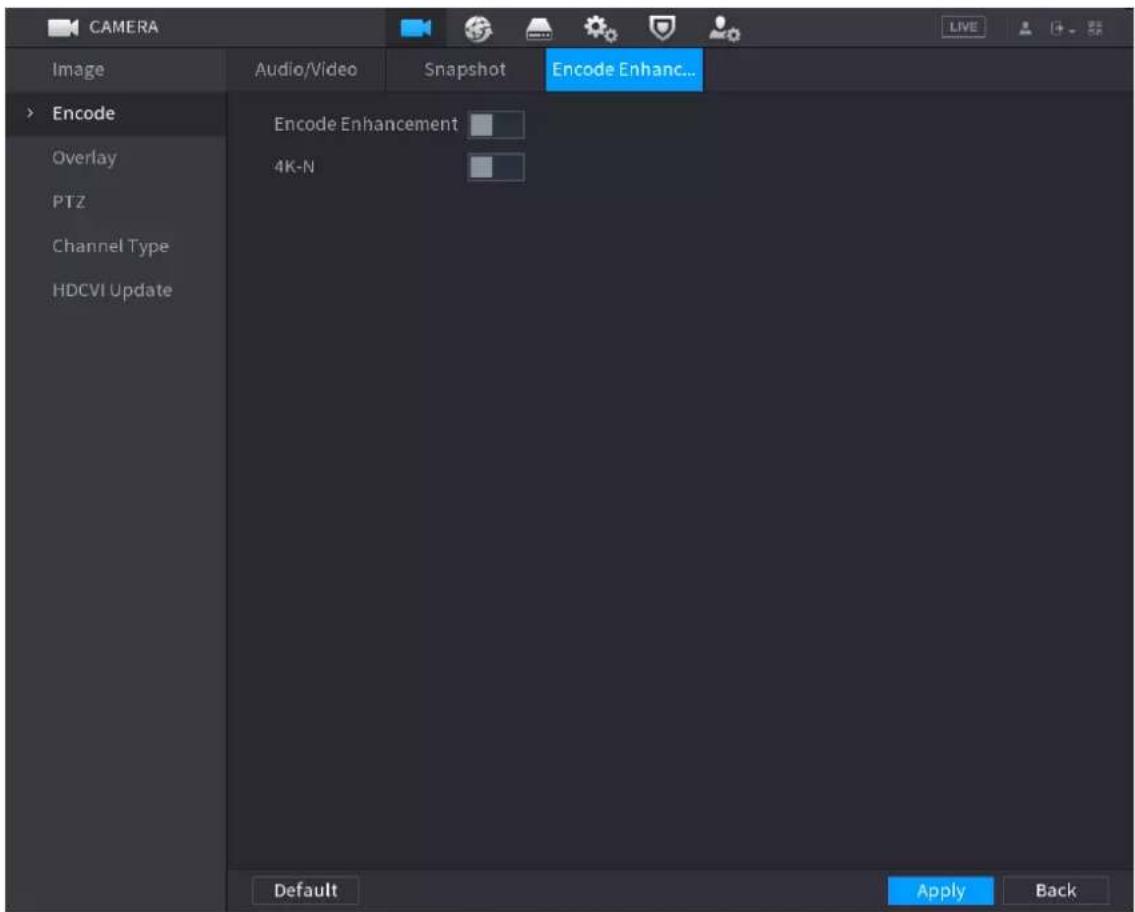
Click the switch to enable it.
When connecting to the new generation 4K cameras, you can enable 4K-N to switch 4K non-live view to 4K-N live view and encoding.
5.5.5 Configuring Overlay Settings
You can configure to display system time and channel name on each channel window in the live view screen.
Step 1 Select Main Menu > CAMERA > Overlay > Overlay.
Figure 5-78 Overlay
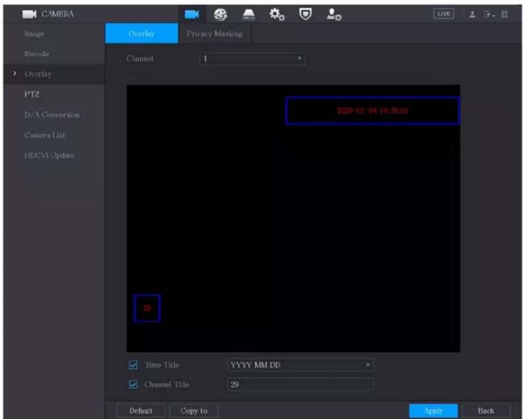
Step 2 Configure the settings for the text overlay parameters.
Table 5-22 Overlay parameters
| Parameter Description | |
| Channel | In the Channel list, select the channel that you want to configure the settings for. |
| Time Title | Select the Time Title checkbox to display the system time on each channel window in the live view screen.In the Time Title list, select time display style. |
| Channel Title | Select the Channel Title checkbox to display the channel name on each channel window in the live view screen.In the Channel Title box, enter the name for the selected channel. |
Step 3 Click Apply to complete the settings.

Click Copy to to copy the settings to other channels.
5.5.6 Configuring Covered Area Settings
Step 1 Select Main Menu > CAMERA > Overlay > Privacy Masking.
Figure 5-79 Privacy masking
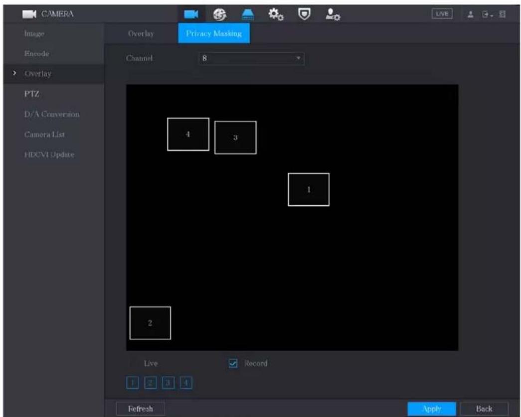
Step 2 Configure the settings for the covered area parameters.
Figure 5-80 Covered area parameters
| Parameter Description | |
| Channel | In the Channel list, select the channel that you want to configure the settings for. |
| Live | Preview: Select the Live checkbox to apply the configured covered block to the selected channel window in the live view screen.Record: Select the Record checkbox to apply the configured covered block to the selected channel window during recording. |
| Record | To configure covering block, do the following:1. Select the Live checkbox or the Record checkbox, or select the both. The "1, 2, 3, 4" buttons are activated.2. Click the buttons to select blocks.3. A triangle solid black block is displayed.4. Drag the block to the area that you want to cover and adjust the size of the block. You can configure total 4 covered blocks. |
Step 3 Click Apply to complete the settings.
5.5.7 Configuring Channel Type
You can configure the channel type as Analog or IP channel.
Step 1 Select Main Menu > CAMERA > Channel Type.
Figure 5-81 Channel type
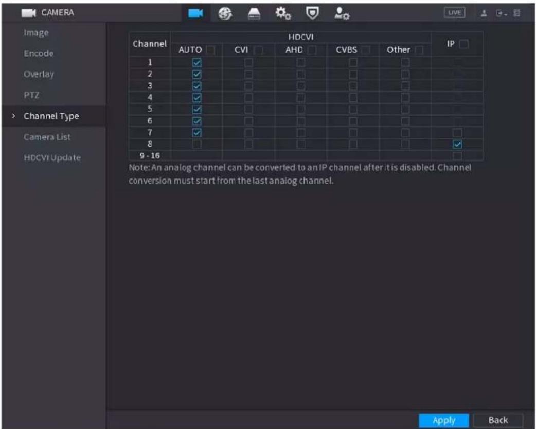
Step 2 Configure the channels.
- Analog Channel: Select the transmission medium such as CVI, AHD, CVBS, and then follow the onscreen instructions to complete the settings.
- IP Channel: You can enable the IP channels by disabling the corresponding analog channels. The Device also provides expanded IP channels for your use, such as the 17–64 channels in 0.

- The 17–64 channels are only for IP camera and the range changes dependent on the model you purchased.
- The channel selection for analog camera or IP camera are in sequence, for example, if you want to select channels for IP camera, you need to select from the last channel number Channel 16 first, which means, you cannot go to select the channel 15 directly until you have selected the channel 16.
Step 3 Click Apply and follow the onscreen instructions to complete the settings.
5.5.8 Upgrading Coaxial Camera
Step 1 Select Main Menu > CAMERA > HDVCI Update.
Figure 5-82 Update
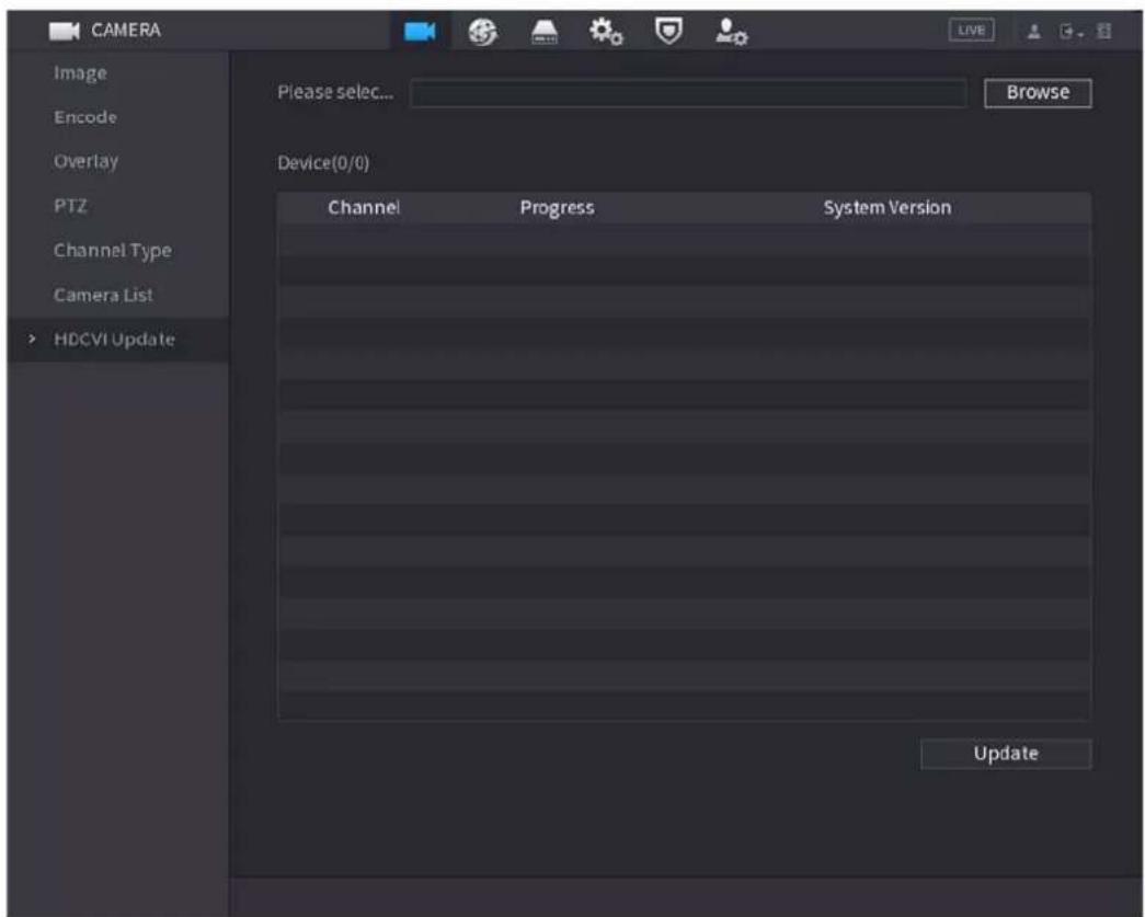
Step 2 Click Browse.
Step 3 Select the upgrade file and then click OK.

You need to insert the USB storage device that contains the upgrading files.
Step 4 Select the checkbox of the channel that you want to upgrade.
Step 5 Click Update.
If the upgrading is successful, the system pops up a message indicating the upgrading is completed.
5.6 Configuring Remote Devices
5.6.1 Adding Remote Devices

This function is available after you have configured the channel type as IP channel as described in previous section, see "5.5.7 Configuring Channel Type".
You can add remote devices by adding the IP address.
Select Main Menu > CAMERA > Camera List > Add Camera, the Add Camera page is displayed.
Figure 5-83 Add camera
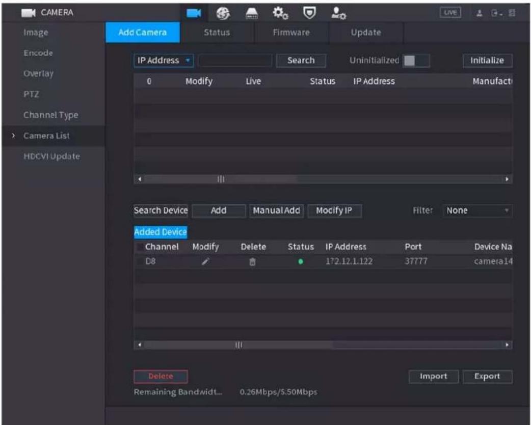
Table 5-23 Parameters
| Parameter Description | |
| Uninitialized | Enable theUninitializedfunction, the uninitialized devices out of the searched devices are displayed in the searched device list. |
| Initialize | Select the uninitialized device from the uninitialized device list, and the clickInitializeto start initializing device. |
| Filter | In theFilterlist, select the remote device type that you want to display in the searched device list.None: Display all types of devices.IPC: Display the front-end devices.DVR: Display all storage devices such as NVR, DVR and HCVR.OTHER: Display the devices that do not belong to IPC or DVR type. |
| Searched Device List | Displays the searched devices. You can view the device information such as status, IP address. |
| Search | ClickSearch, the searched devices display in the searched device list.To adjust the display sequence, in the title line, you can click the IP address, Type or Device Name text. For example, click the IP address text, the sequence icon is displayed."*” is displayed next to the added device. |
| Add | In theSearched Device Listarea, select the device that you want to add. |
| Manual Add | Add the device by manually configuring settings such as IP address, channel selection. For details, see "5.6.1.3 Adding Remote Devices Manually". |
| Added Device List | Displays the added devices. You can edit and delete the device, and view the device information. |
| Delete | Select the checkbox of the added device, and then click Delete to delete the added device. |
| Import | Select the searched devices and then click Import to import the devices in batches. |
| Export | Select the added devices and then click Export. The exported devices information is saved into the USB storage device. |
5.6.1.1 Initializing Remote Devices
You can reset the password and IP address of the remote devices through initializing.
Step 1 Click Search Device.
The devices found are displayed in the table.
Figure 5-84 Search result
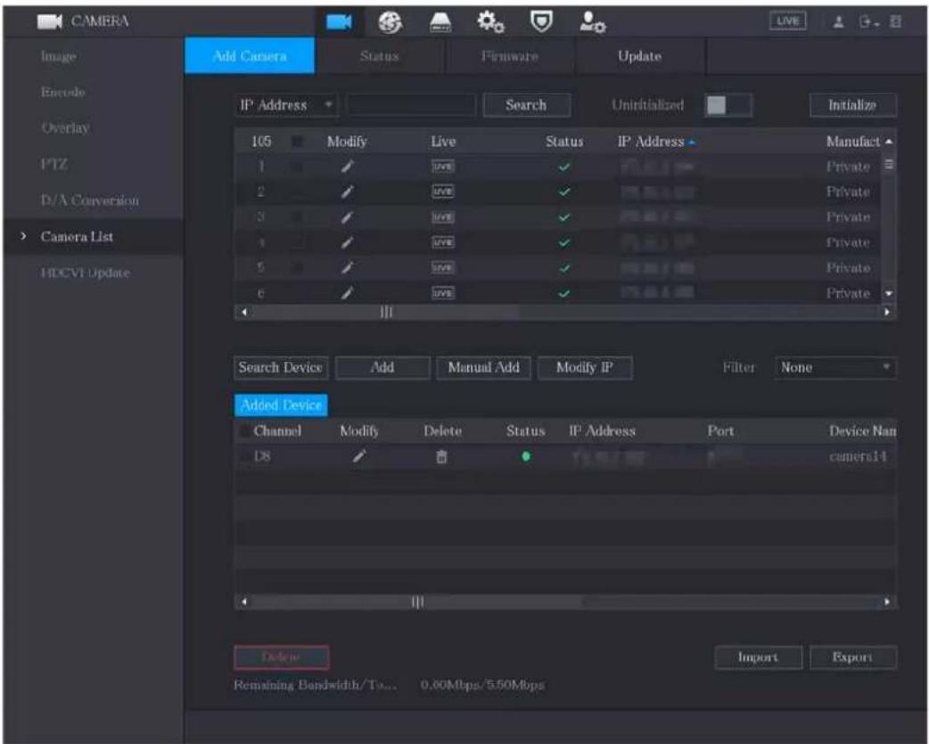
Step 2 Enable the Initialized function.
The uninitialized devices are displayed.
Figure 5-85 Uninitialized devices
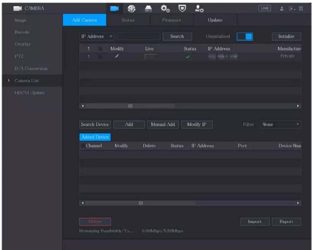
Step 3 Select the uninitialized device that you want to initialize.
Step 4 Click Initialize.
Figure 5-86 Enter password
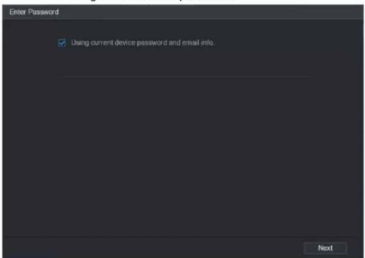
Step 5 Configure the password and email information.

If you select the Using current device password and email info checkbox, the remote device automatically uses the current password and email information, so you do not need to set the password and email address again and can go to Step 6.
1) Clear the Using current device password and email info checkbox.
Figure 5-87 Password setting
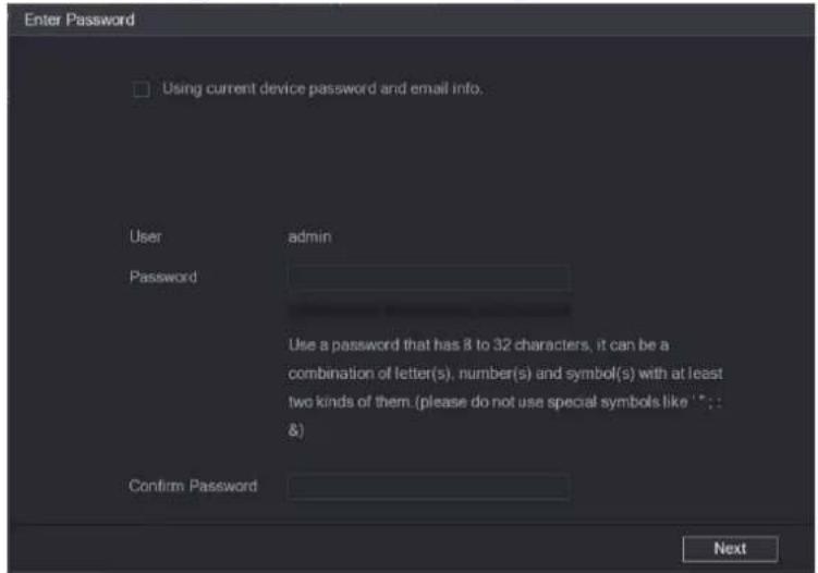
2) Configure the settings for the password setting parameters.
Figure 5-88 Password parameters
| Parameter Description | |
| User The default is admin. | |
| Password | The password must consist of 8–32 non-blank characters and contain at least two types of the following characters: uppercase, lowercase, numbers, and special characters (excluding '"; : &).Enter a strong password according to the password strength bar indication. |
| Confirm Password | |
3) Click Next.
Figure 5-89 Password protection
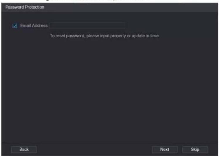
4) Select the Email Address box and enter the email address that you want to reserve for password reset in the future.

If you do not want to set the reserved email address, click Skip.
Step 6 Click Next.
Figure 5-90 Network
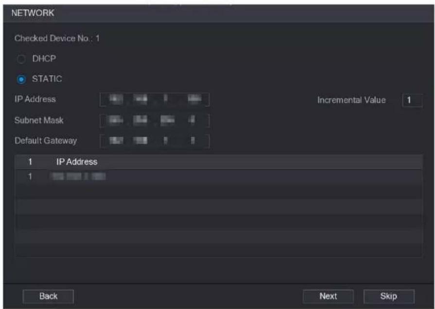
Step 7 Configure the IP address.
- Select the DHCP checkbox, you do not need to enter the IP address information, because the system will allocate one IP address to the remote device.
- Select the STATIC checkbox, you need to enter the IP address, subnet mast, default gateway, and incremental value. The system will allocate the IP address to the remote devices by progressively increasing the last part of the IP address when initializing devices in batches.

When configuring IP address for multiple remote devices which were not in the same network segment, these remote devices will belong to the same network segment after configuration.
Step 8 Click Next.
The initializing is started.
Figure 5-91 Initialization finished
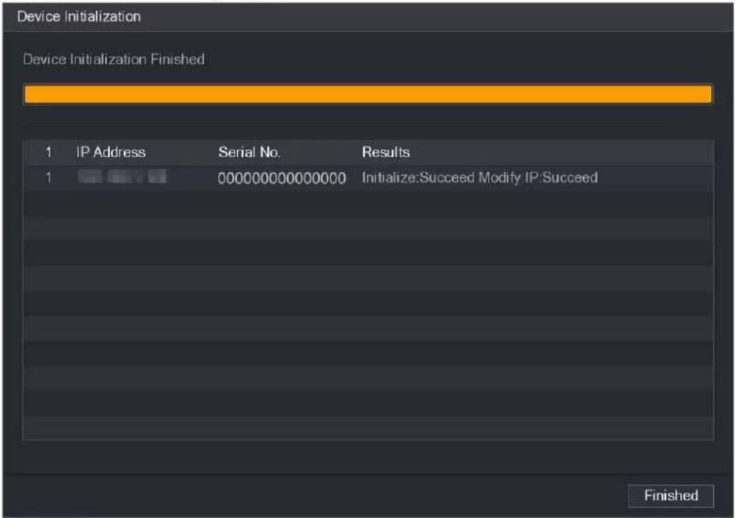
Step 9 Click Finished to complete the settings.
5.6.1.2 Adding Remote Devices Automatically
Step 1 On the Registration page, click Device Search The devices found are displayed.
Figure 5-92 Search device
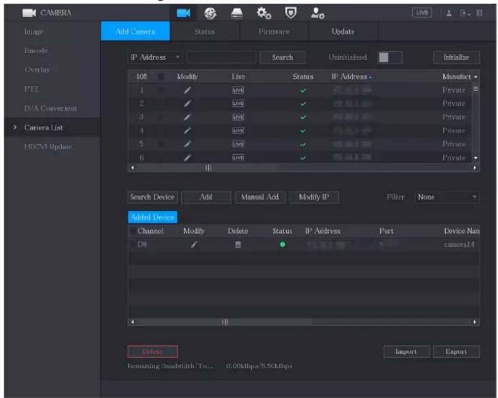
Step 2 Select the checkbox of the device.
Step 3 Click Add.
The device is added into the Added Device area.

- You can also double-click the device to add it into the Added Device area.
• You can add devices in batches.
5.6.1.3 Adding Remote Devices Manually
Step 1 On the Add Camera page, click Manual Add.
Figure 5-93 Manual add
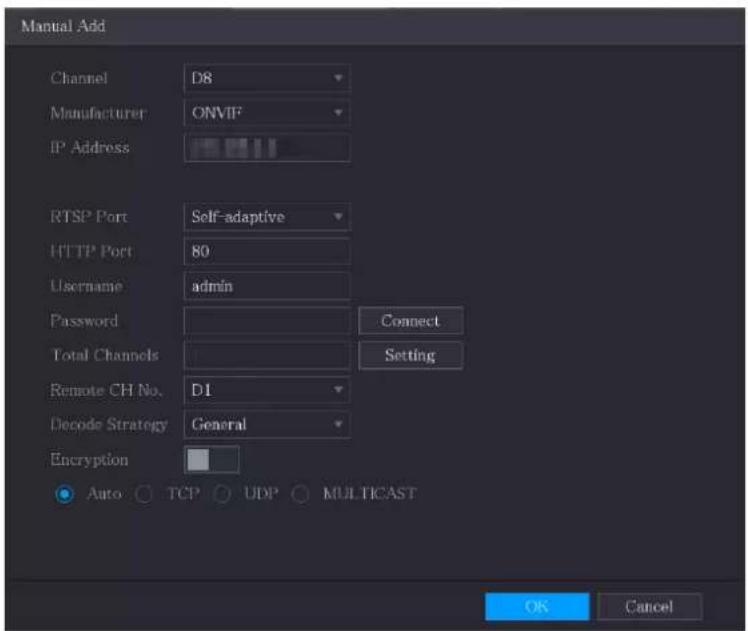
Step 2 Configure the settings for the manual adding device parameters.
Figure 5-94 Manual add parameters
| Parameter Description | |
| Channel | In the Channel list, select the channel that you want use on the Device to connect the remote device. |
| Manufacturer | In the Manufacturer list, select the manufacturer of the remote device. |
| IP Address | In the IP Address box, enter the IP address of remote device.The default is 192.168.0.0 which the system cannot connect to. |
| RTSP Port | The default value setting is 554. You can enter the value according to your actual situation. |
| HTTP Port | The default value setting is 80. You can enter the value according to your actual situation.If you enter other value, for example, 70, and then you should enter 70 after the IP address when logging in the Device by browser. |
| TCP Port | The default value setting is 37777. You can enter the value according to your actual situation. |
| Parameter Description | |
| Username | Enter the username of the remote device. |
| Password | Enter the password of the user for the remote device. |
| Remote CH No. | Enter the remote channel number of the remote device that you want to add. |
| Decoder Strategy | In the Decoder Strategy list, select Default, Realtime, or Fluent. |
| Protocol Type | If the remote device is added through private protocol, the default type is TCP.If the remote device is added through ONVIF protocol, the system supports Auto, TCP, UDP, or MULTICAST.If the remote device is added through other manufacturers, the system supports TCP and UDP. |
| Encryption | If the remote device is added through ONVIF protocol, enabling the Encryption checkbox will provide encryption protection to the data being transmitted.To use this function, the HTTPS function should be enabled for the remote IP camera. |
Step 3 Click OK to save the settings.

- Only one device can be added manually at one time.
• indicates successful connection and indicates connection failed.
5.6.1.4 Modifying or Deleting Remote Devices
You can modify and delete the added devices.
• To modify the remote devices, do the following:
Step 1 Click or double-click a device.
Figure 5-95 Modify
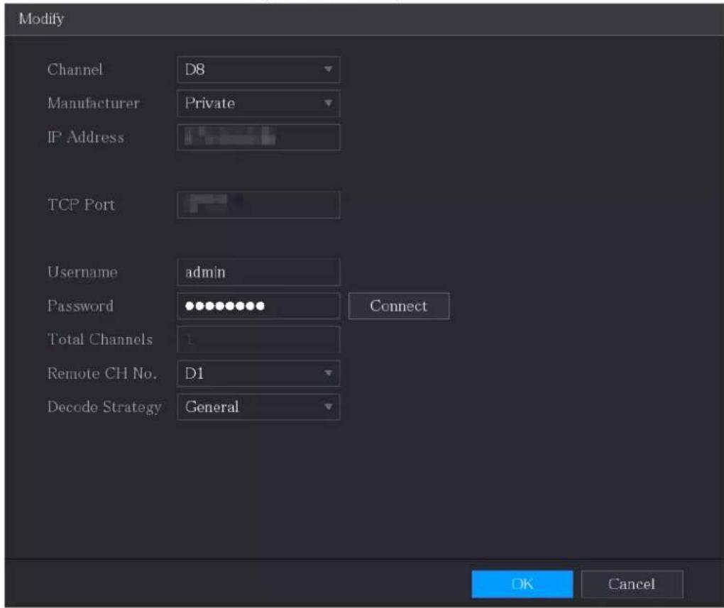
Step 2 In the Channel list, select the channel that you want to modify settings for.
Step 3 Click OK to save the settings.
• To delete one or more added devices, do the following:
◇ Click to delete one device.
Select the checkbox of the devices that you want to delete, and then click Delete.
5.6.1.5 Modifying IP Address
You can modify a single IP address or multiple IP addresses of remote devices at one time.

You can only modify the IP address of initialized cameras.
• To modify a single IP address, do the following:
Step 1 In the Searched Device list area, click for the device that you want to modify IP.
Figure 5-96 Modify IP
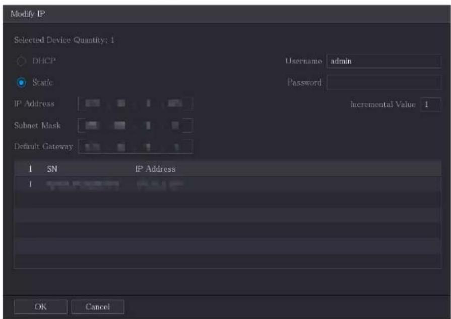
Step 2 Configure the settings for IP address, subnet mask, default gateway, username, and password.
Step 3 Click OK to save the settings.
• To modify IP address in batches, do the following:
Step 1 In the Searched Device list area, select the devices that you want to modify IP address in batches.
Step 2 Click

Figure 5-97 Modify IP
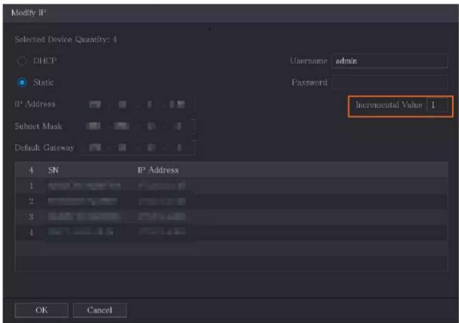
Step 3 Set incremental value.

The system will add the incremental value to the fourth segment of IP addresses of selected devices.
Step 4 Configure the settings for start IP address (the IP address is allocated in sequence), subnet mask, default gateway, username, and password.
Step 5 Click OK to save the settings.
5.6.1.6 Exporting IP Address
You can export the added IP address to the USB storage device.

The exported information is saved in .csv file, which includes IP address, port number, channel number, manufacturer, username, and password.
Step 1 Insert the USB storage device to the USB port of the Device.
Step 2 Click Export.
Figure 5-98 Browse
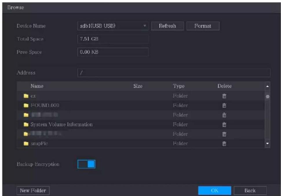
Step 3 Configure the save path.
Step 4 Click OK to save the settings.
A pop-up message indicating "Successfully exported" is displayed.
Step 5 Click OK.

When exporting IP address, the Backup Encryption checkbox is selected by default. The file information includes IP address, port, channel number, manufacturer, username, and password.
- If you select the Backup Encryption checkbox, the file format is .backup.
- If you clear the Backup Encryption checkbox, the file format is .csv. In this case, there might be a risk of data leakage.
5.6.1.7 Importing IP Address
You can add remote devices by importing IP address information.
Step 1 Insert the USB storage device to the USB port of the Device.
Step 2 Click Import.
Figure 5-99 Browse
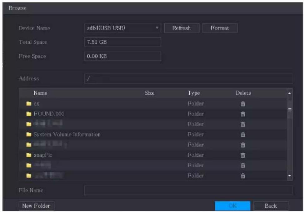
Step 3 Select the file that you want to import.
Step 4 Click OK to start importing.
After importing is completed, a pop-up message indicating "The import succeeded" is displayed.

If the IP address that you want to import already exists in the Device, the system will pop up a message to ask you whether to overwrite the existing content.
- Click OK to replace the existing one.
- Click Cancel to add it as a separate device in the Added Device area.

- You can edit the exported .csv file and be cautious not to change the file format; otherwise the file cannot be imported as it will be judged as invalid.
- The language of .csv file must match the Device language.
- The import and export through customized protocol is not supported.
5.6.2 Managing Remote Devices
You can view the status of remote devices and upgrade.
5.6.2.1 Viewing Status
You can view the device information such as connection status, IP address, motion detection, video loss detection, camera name, and manufacturer.
Select Main Menu > CAMERA > Camera List > Status.
5.6.2.2 Viewing Firmware Information
You can view the device firmware information such as channel number, IP address, manufacturer, system version, video input, audio input, and alarm in.
Select Main Menu > CAMERA > Camera List > Firmware.
Figure 5-100 Firmware
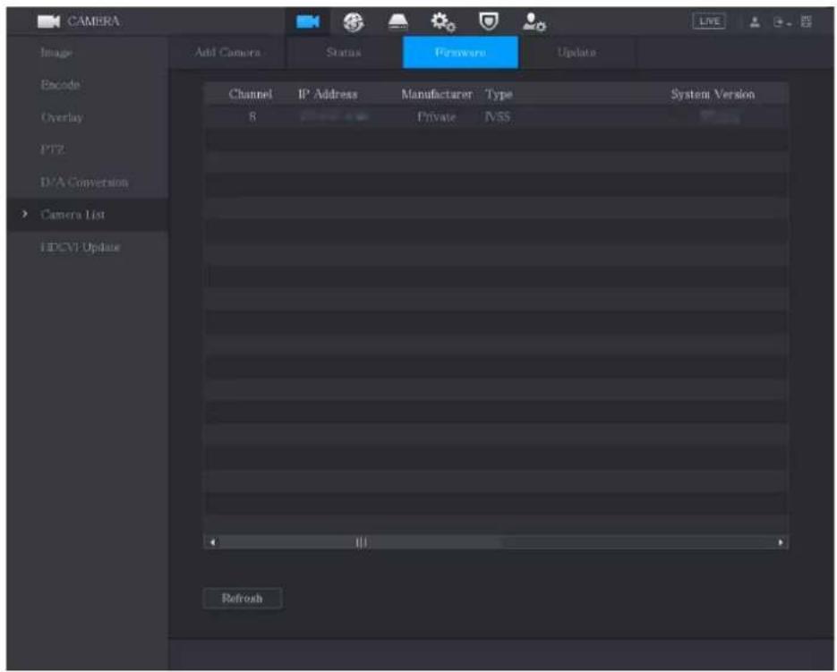
5.6.2.3 Upgrading Remote Devices
Step 1 Select Main Menu > CAMERA > Camera List > Update.
Figure 5-101 Update
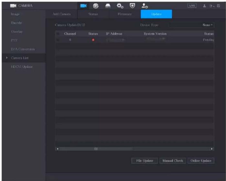
Step 2 Upgrade the device.
- File Update
1) Insert a USB storage device containing the upgrade files into the USB port of the Device.
2) Select the devices that you want to upgrade.
3) Click File Update.
The File Update page is displayed.
4) Select the upgrading files and click Apply.
- Online Update
1) Click Detect or select the checkbox the device that you want to upgrade and click Manual Check.
The system starts detecting if there is a new version on the online server.
2) Select the checkbox of all the devices that have new version.
3) Click Online Update.

- The system will pop up a message to indicate if the upgrading is successful.
- You can use the Type list to filter the devices so that you can find the devices quickly.
5.7 Configuring Record Settings
You can record video manually or automatically and configure the recording settings to main stream and sub stream respectively.
5.7.1 Enabling Record Control

- Manual recording operation requires the user have the permission to access STORAGE settings.
- Check to ensure the HDD installed in the Device has been formatted properly.
To enter the record control page, do the following:
Step 1 Right-click on the live view screen, the shortcut menu is displayed. On the shortcut menu, select Manual Control > Record Control.
Figure 5-102 Record mode
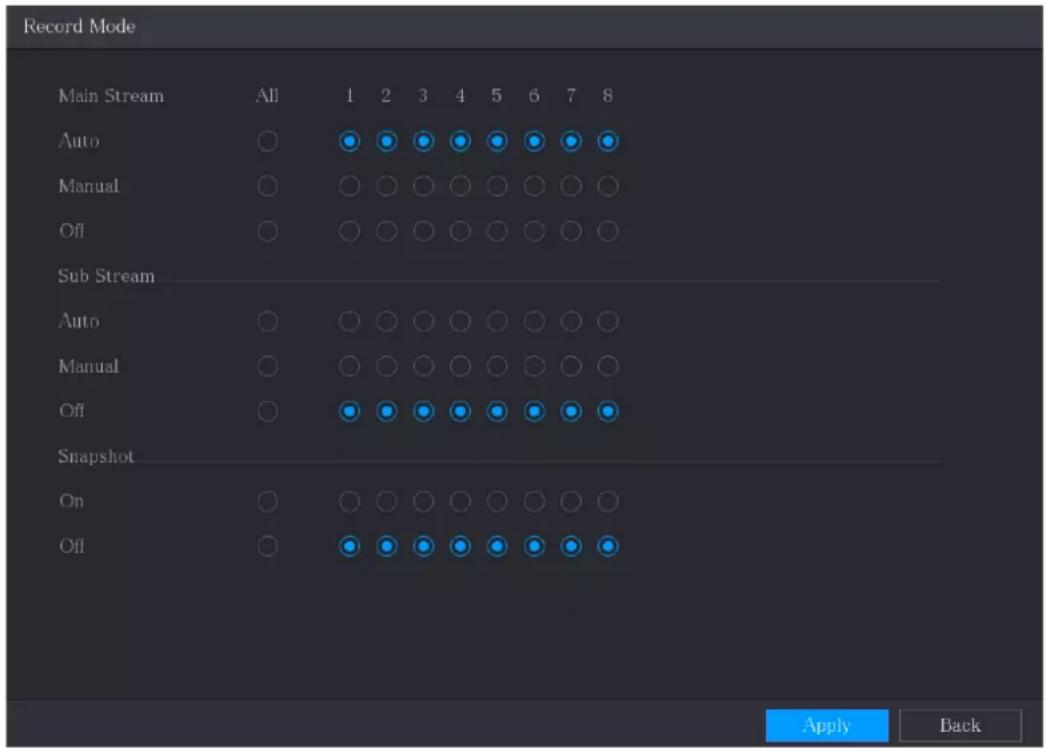
Step 2 Configure the settings for the record control parameters.
Table 5-24 Record control parameters
| Parameter Description | |
| Channel | Displays all the analog channels and the connected digital channels. You can select a single channel or select All. |
| Main Stream/Sub Stream | ● Auto: Automatically record according to the record type and recording time as configured in the recording schedule.● Manual: Keep general recording for 24 hours for the selected channel.● Stop: Do not record. |
| Snapshot | Enable or disable the scheduled snapshot for the corresponding channels. |
Step 3 Click Apply.
5.7.2 Configuring Recorded Video Storage Schedule
You need to configure the storage schedule for the recorded video so that the recorded video can be saved. For details, see "5.1.4.9 Configuring Recorded Video Storage Schedule".
5.8 Configuring Snapshot Settings
5.8.1 Configuring Snapshot Trigger
The snapshot is divided into scheduled snapshot, event triggered snapshot, and face detection triggered snapshot. When the both are enabled, the event triggered snapshot has the priority.
- If there is no alarm event, the system performs scheduled snapshot.
- If there is any alarm event, the system performs event triggered snapshot.
5.8.1.1 Configuring Scheduled Snapshot
Step 1 Right-click on the live view screen, the shortcut menu is displayed.
Step 2 On the shortcut menu, select Manual Control > Record Control.
Step 3 In the Snapshot area, enable the snapshot for the channels if needed.
Figure 5-103 Enable snapshot
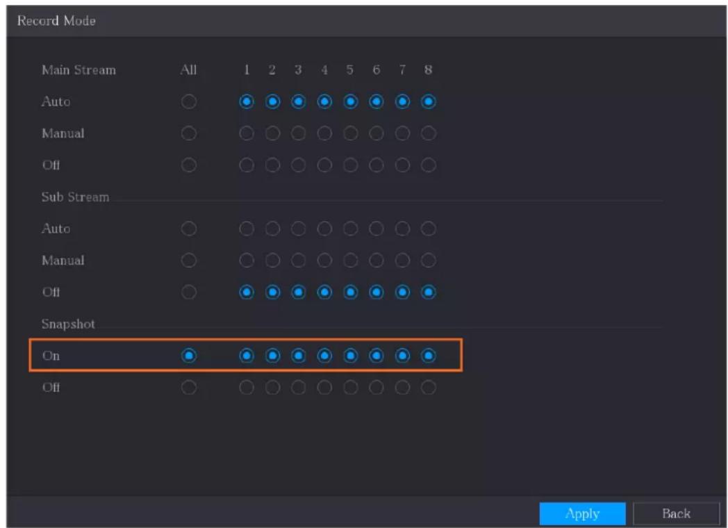
Step 4 Select Main Menu > CAMERA > Encode > Snapshot.
Step 5 In the Type list, select Scheduled, and then configure other parameters.
Figure 5-104 Type list
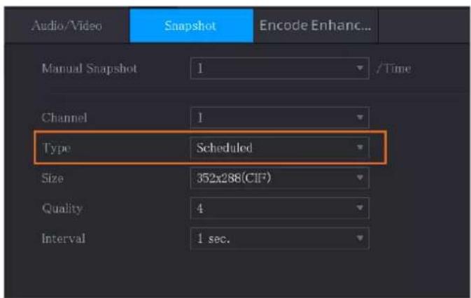
Step 6 Click Apply to save the settings.
- If you have configured the snapshot schedule, the configuration has been completed.
- If you have not configured the snapshot schedule, see "5.1.4.10 Configuring Snapshot Storage Schedule".
5.8.1.2 Configuring Event Triggered Snapshot
Step 1 Select Main Menu > CAMERA > Encode > Snapshot.
Step 2 In the Type list, select Event, and then configure other parameters.
Figure 5-105 Event
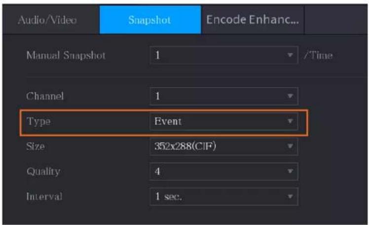
Step 3 Select Main Menu > ALARM > Video Detection, and select the event type to configure, for example, select the Motion Detection tab.
Figure 5-106 Motion detection
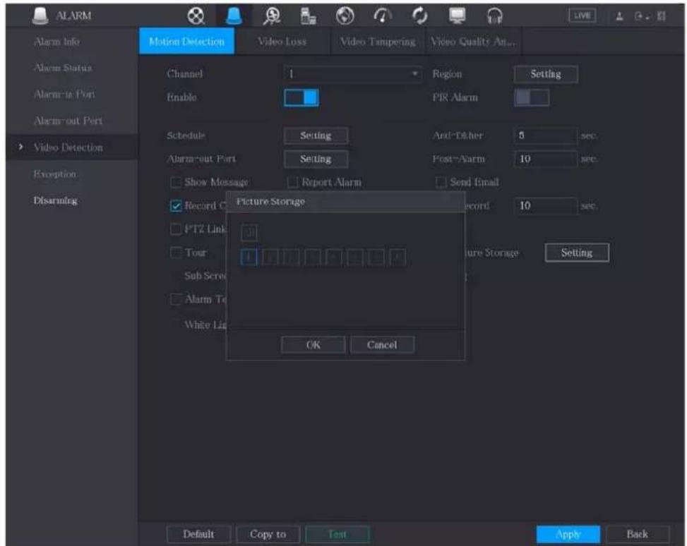
Step 4 Click Setting next to Picture Storage checkbox and select the corresponding channel.
Step 5 Click Apply.
5.8.2 Configuring Snapshot Storage Schedule
You need to configure the storage schedule for the snapshot so that the snapshot can be saved. For details, see "5.1.4.10 Configuring Snapshot Storage Schedule".
5.8.3 Backing up Snapshots to FTP
Step 1 Select Main Menu > STORAGE > FTP.
Figure 5-107 FTP
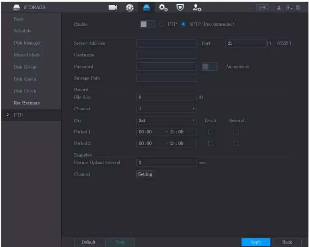
Step 2 Enable the FTP function and configure the parameters. For details, see "5.18.9 Configuring FTP Storage Settings".
The snapshots will be uploaded to FTP for backup.
5.9 Playing Back Video
5.9.1 Enabling Record Control

- Manual recording operation requires the user have the permission to access STORAGE settings.
- Check to ensure the HDD installed in the Device has been formatted properly.
To enter the record control page, do the following:
Step 1 Right-click on the live view screen, the shortcut menu is displayed. On the shortcut menu, select Manual Control > Record Mode.
Figure 5-108 Record mode
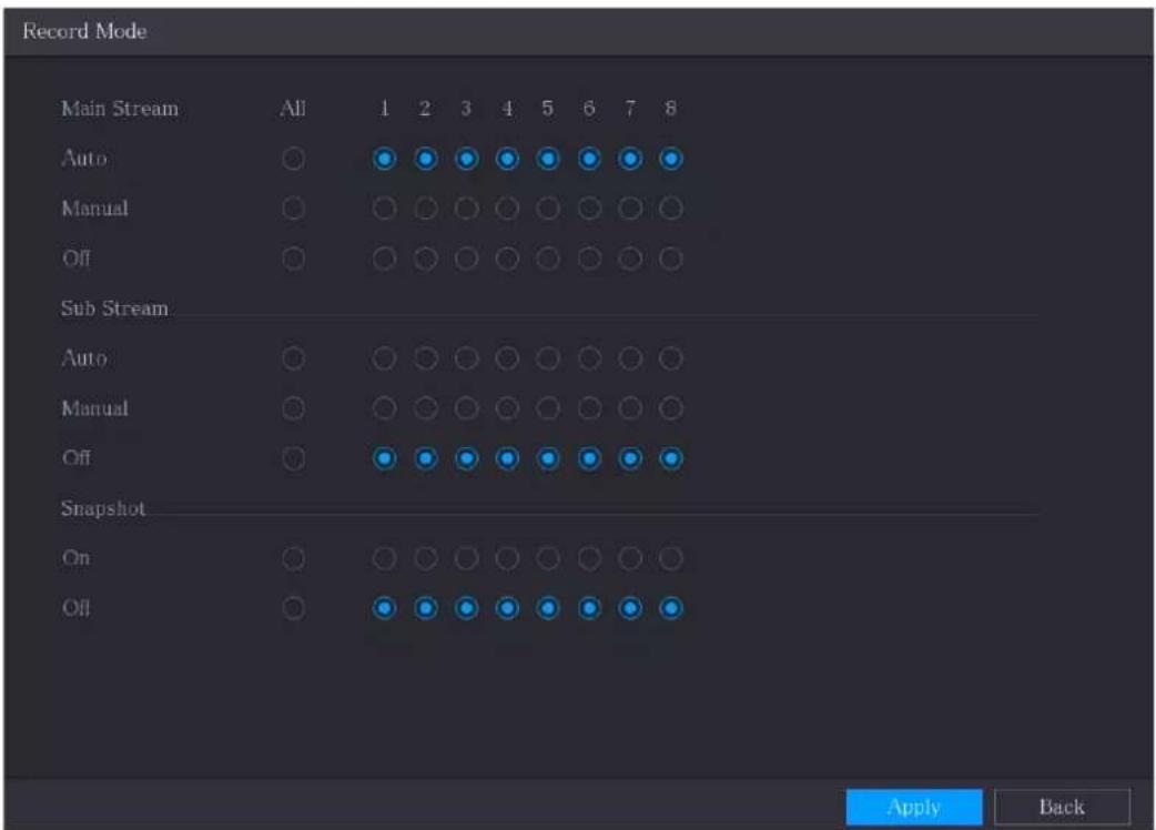
Step 2 Configure the settings for the record control parameters.
Table 5-25 Record control parameters
| Parameter Description | |
| Channel | Displays all the analog channels and the connected digital channels. You can select a single channel or select All. |
| Main Stream/Sub Stream | ● Auto: Automatically record according to the record type and recording time as configured in the recording schedule.● Manual: Keep general recording for 24 hours for the selected channel.● Stop: Do not record. |
| Snapshot | Enable or disable the scheduled snapshot for the corresponding channels. |
5.9.2 Instant Playback
You can use the instant playback function to play back the previous 5 seconds to 60 minutes of the recorded video in any channel. For details about instant playback function, see "5.2.2.1 Instant Playback".
5.9.3 Video Playback
You can search for and play back the recorded video saved on the Device.
Select Main Menu > Search.
Figure 5-109 Video search
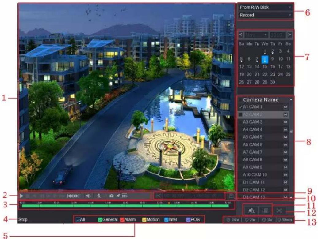
Figure 5-110 Video search description
| No. | Function | Description |
| 1 Display Window | Display the searched recorded video or picture.Supports simultaneously playing in single-channel, 4-channel, 9-channel, and 16-channel.When playing back in a single channel, click and hold to select the area that you want to enlarge.The area is enlarged after the left mouse button is released.To exit the enlarged status,right-click on the image. | |
| 2 | Playback Controls Bar | Playback control buttons.For details about the control buttons, see "5.9.3.1 Introducing Playback Controls". |
| 3 Time Bar | Display the type and time period of the current recorded video.In the 4-channel layout, there are four time bars are displayed; in the other view layouts, only one time bar is displayed.Click on the colored area to start playback from a certain time.In the situation when you are configuring the settings, rotate the wheel button on the time bar, the time bar is zooming in from 0. In the situation when playback is ongoing, rotate the wheel button on the time bar, the time bar is zooming from the time point where the playback is located.Time bar colors: Green indicates general type; Red indicates external alarm; Yellow indicates motion detection; Blue indicates intelligent events; Purple indicates POS events.For some models, when you are clicking on the blank area in the time bar, the system automatically jumps to the next time point where there is a recorded video located.Click and hold the time bar, and the mouse pointer shall change to a hand icon, and then you can drag to view the playback of the target time.You can drag the vertical orange line on the time bar to rapidly view the playback in iframe format.When playing back video in one channel mode, you can move mouse pointer to time bar to display thumbnail pictures for the video of target time.When playing back video, you can select other channels as needed. The time bar of newly added channels will be added up to the time bar of earlier base channels. The type and time period of newly added channels are the same with early base channels. | |
| 4 Play | Status | Includes two playback status:PlayandStop. |
| 5 | Record type | Select the checkbox to define the recording type to search for. |
| 6 Search type | Select the content to play back:Record, Picture, Subperiod. For details about the selecting search type, see "5.9.3.2 Selecting Search Type". | |
| 7 Calendar | Click the date that you want to search, the time bar displays the corresponding record.The dates with record or snapshot have a small solid circle under the date. | |
| 8 | View Layout and Channel Selection | In the Camera Name list, select the channel(s) that you want to play back.The window split is decided by how you select the channel(s). For example, if you select one channel, the playback is displayed in the single-channel view; if you select two to four channels, the playback is displayed in the four-channel view. The maximum is eight channels.Click  to switch the streams. indicates main stream, and to switch the streams. indicates main stream, and  icates sub stream. icates sub stream. |
| 9 Video Splice | Splice a section of recorded video and save it. For details about splicing a recorded video, see "5.9.3.3 Clipping Recorded Video". | |
| 10 | Backup | Back up the recorded video files. For details, see "5.9.3.4 Backing up Recorded Video." |
| 11 | List Display | This area includes Tag List and File List.T867: Click the Tag List button, the marked recorded video list is displayed. Double-click the file to start playing.TZGA: Click the File List button, the searched recorded video list is displayed. You can lock the files. For details, see "5.9.9 Using the File List". |
| 12 | Full Screen | Click  to display in full screen. In the full screen mode, point to the bottom of the screen, the time bar is displayed. Right-click on the screen to exit full screen mode. to display in full screen. In the full screen mode, point to the bottom of the screen, the time bar is displayed. Right-click on the screen to exit full screen mode. |
| 13 | Time Bar Unit | You can select 24 hr, 2 hr, 1 hr, or 30 min as the unit of time bar. The time bar display changes with the setting. |
5.9.3.1 Introducing Playback Controls Bar
You can perform the operations such as control the speed of playback, add mark, and take snapshots through the playback controls bar.
Figure 5-111 Playback control bar


The play backward function and playback speed are dependent on the product version. The actual product shall govern. You can also contact the technical support to consult the hardware version information.
Table 5-26 Playback control bar description
| Icon Function | |
  | Play/Pause.During playing back, you can switch between play and pause. |
 [XKBK] [XKBK] | Stop.During playing back, you can click the Stop button to stop playback. |
 [WGDE] [WGDE] | Play backward.During playing back, click the Play Backward button to backward play the recorded video, the button switches to ; click to stop playing backward.During playing back, click to start playing forward. |
[B2X4]  | Previous and next frame.When the playback is paused, click or click to play single-frame recorded video.When playing back single-frame recorded video, click to start playing forward. |
  | Slow playback.During playing back, click to set the speed of slow playback as SlowX1/2, SlowX1/4, SlowX1/8, or SlowX1/16.During fast playback, click to slow down the speed of fast playback. |
  | Fast playback.During playing back, click to set the speed of fast playback as FastX2, FastX4, FastX8, or FastX16.During slow playback, click to speed up slow playback. |
  | Previous day and next Day.Click or click to play the previous day or next day of the current recorded video. |
| Adjust volume of playback. | |
  | Enable smart search function. For details about using the smart search, see "5.9.4 Smart Search". |
  | Add filter criteria of smart search. You can select Human, Vehicle, or uncheck. For details about using the smart search, see "5.9.4 Smart Search".In the full screen mode, click to take a snapshot and save into the USB storage device or mobile HDD. |
 | Add Mark for the recorded view. For details about adding mark, see "5.9.6 Marking and Playing Back Video". |
 | Show or hide POS information.During single-channel playback, click to show or hide POS information on the screen. |
 | During playback, click this icon to display or hide AI rulers. For more details, see "5.9.5 Showing AI Rule during Playback". |
 | Show playback video in full screen. |
5.9.3.2 Selecting Search Type
You can search the recorded videos, splice, or snapshots from HDD or external storage device.
- From R/W Disk: Recorded videos or snapshots playback from HDD of the Device.
Figure 5-112 From R/W disk
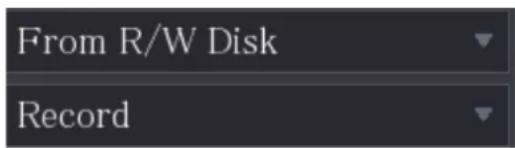
- From I/O Device: Recorded videos playback from external storage device. Click Browse, select the save path of recorded video file that you want to play. Double-click the video file or click ▶ to start playing.
Figure 5-113 From I/O device
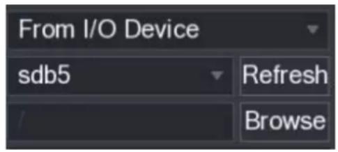
5.9.3.3 Clipping Recorded Video
During playback, clip sections of recorded video and save to the USB storage device.
Figure 5-114 Clip

Step 1 Select a recorded video that you want to play.

- Click ▶ to start playing from the beginning.
- Double-click anywhere in the time bar colored area to start playback.
Step 2 Click on the time bar to select the start time, and then click ✗ to start clipping.
Step 3 Click on the time bar to select the end time, and then click to stop clipping.
Step 4 Click .


- You can clip the video of a single-channel or multiple channels.
• Maximum 1024 files can be backed up at one time.
• The files that are selected in the File List cannot be clipped.
5.9.3.4 Backing up Recorded Video
You can back up the recorded video file or splice video file into the USB storage device.
Step 1 Select the recorded video file that you want to back up. You can select the following two types of files:
- Recorded video file: Click 📄, the File List area is displayed. Select the file(s) that you want to back up.
- Splice video file. For details about splicing video file, see "5.9.3.3 Clipping Recorded Video".
Step 2 Click.

Figure 5-115 Backup
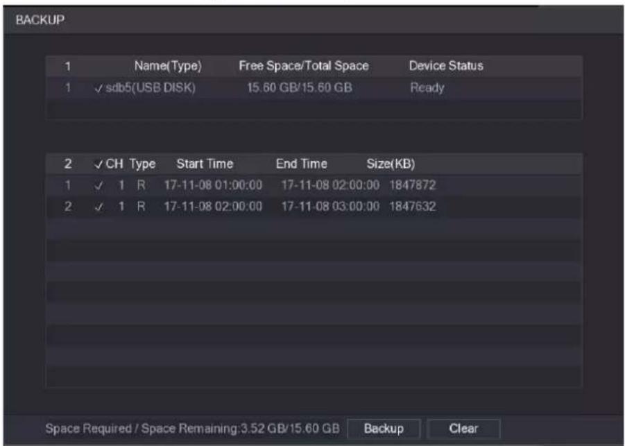
Step 3 Click Backup.

If you do not want to back the file, clear the checkbox.
5.9.4 Smart Search
During playback, you can analyze a certain area to find if there was any motion detection event occurred. The system will display the images with motion events of the recorded video.

This function is available on select models.
To use the Smart Search function, you need to enable the motion detection for the channel by selecting Main Menu > ALARM > Video Detection > Motion Detection.
To use the Smart Search function, do the following:
Step 1 Select Main Menu > SEARCH, the video search page is displayed.
Step 2 In the Camera Name list, select the channel(s) that you want to play.
Step 3 Click ▶ or double-click anywhere in the time bar colored area to start playback.
Step 4 Click.
The grid is displayed on the screen.

• Only single-channel supports smart search.
- If multi-channels are selected, double-click on the channel window to display this channel only on the screen, and then you can start using smart search function.
Step 5 Drag the pointer to select the searching area.

The grid area supports 22 × 18 (PAL) and 22 × 15 (NTSC).
Step 6 Click to add filter criteria. You can check Human box, Vehicle box, or uncheck.
● Human: Display the motion alarm of human during selected time and searching area.
● Vehicle: Display the motion alarm of vehicle during selected time and searching area.
- Unchecking: Display the general motion alarm which includes both human and vehicle, during selected time and searching area.
Step 7 Click.
The screen starts playing back the motional splices of recorded video for the selected searching area.
Step 8 Click to exit the smart searching while playback.
5.9.5 Showing AI Rule during Playback
To use the AI rule showing function, do the following:
Step 1 Select Main Menu > SEARCH.
Step 2 In the Camera Name list, select the channel(s) that you want to play.
Step 3 Click ▶ or double-click anywhere in the time bar colored area to start playback. You can see the AI rule during playback. This function is enabled by default.
Figure 5-116 Playback
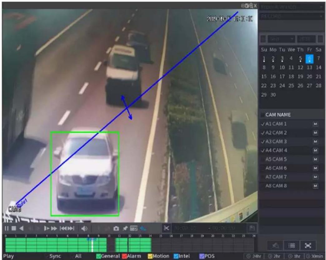


5.9.6 Marking and Playing Back Video
You can mark the recording for somewhere important. Then you can easily find the marked recording by searching time and mark name.
Marking a Video
Step 1 Select Main Menu > SEARCH.
Step 2 In the playback mode, click

Figure 5-117 Add tag
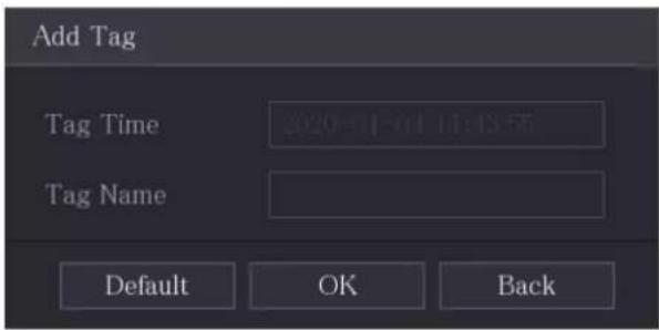
Step 3 In the Tag Name box, enter a name.
Step 4 Click OK.
This marked video file displays in the Tag List.
Playing Back Marked Video

This function is supported on single-channel playback.
Step 1 In the Camera Name list, select one channel.
Step 2 Click.

Figure 5-118 Mark list
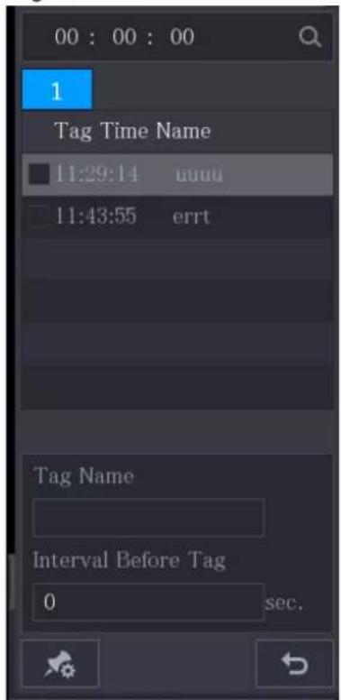
Step 3 Double-click the file that you want to play back.
To search the marked video by time, in the SEARCH box on the top of the page, enter the
time, and then click

Playing Back Time before the Tag
You can configure to play N seconds of the tagged video before the tagged time.
Step 1 In the Tag Name box, enter the name of a tagged video.
Step 2 In the Interval Before Tag box, enter N seconds.
Step 3 Click.

The playback starts from N seconds before the tagged time.

If there is N seconds exist before the marked time, the playback starts from N seconds before the tagged time. If there is not, it plays back as much as there is.
Managing Tagged Video
On the Tag List page, click

Figure 5-119 Tag management
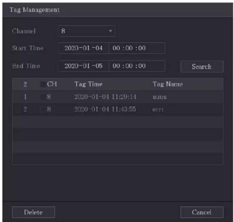
- Be default, it manages all the tagged videos of the selected channel.
- To search the tagged video, select channel number from the Channel list, enter time in Start Time box and End Time box, and then click Search.
• All the tagged videos display in time order.
• To modify the name of tagged video, double-click a tagged video. - To delete the marked video, select the tagged video, and then click Delete.

After opening the Tag Management page, the playback will pause until exiting this page. If the marked video that was in playing back is deleted, the playback will start from the first tagged video in the Tag List.
5.9.7 Playing Back Snapshots
You can search and play back the snapshots.
Step 1 Select Main Menu > SEARCH.
Step 2 In the Search Type list, select Picture.
Step 3 In the Channel list, select a channel number.
Step 4 In the Calendar area, select a date.
Step 5 Click.

The system starts playing snapshots according to the configured intervals.
5.9.8 Playing Back Splices
You can clip the recorded video files into splices and then play back at the same time to save your time.

This function is available on select models.
Step 1 Select Main Menu > SEARCH.
Step 2 In the Search Type list, select Subperiod; In the Split Mode list, select 4, 9, or 16.
Figure 5-120 Subperiod
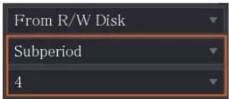
Step 3 In the Calendar area, select a date.
Step 4 In the Camera Name list, select a channel.

Only single-channel supports this function.
Step 5 Start playing back splices.
- Click ▶, the playback starts from the beginning.
- Double-click anywhere on the time bar, the playback starts from where you click.
Figure 5-121 Time bar

Every recorded video file must be at least five minutes. If a recorded video file is less than 20 minutes but still choose to split into four windows, the system will automatically adjust the windows quantity to ensure every splice is more than five minutes, and in this case it is possible that there are no images are displaying in some windows.
5.9.9 Using the File List
You can view all the recorded videos within a certain period from any channel in the File List.
Step 1 Select Main Menu > VIDEO.
Step 2 Select a channel(s).
Step 3 Click.

Figure 5-122 File list
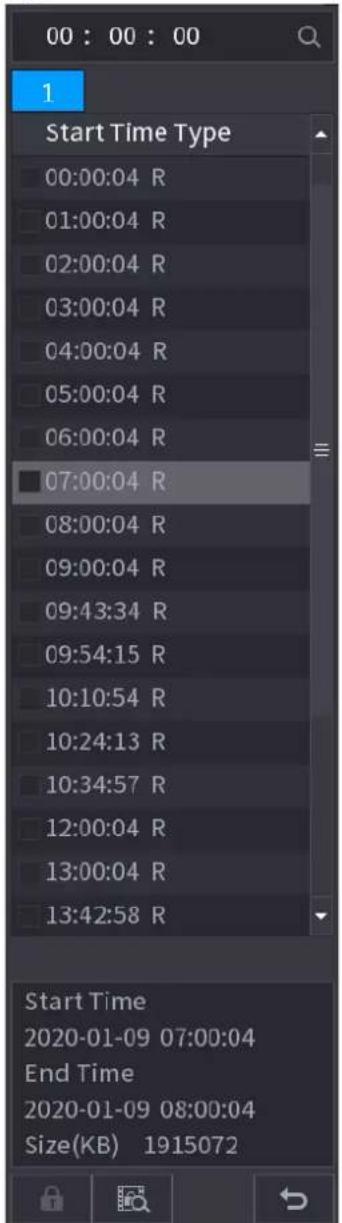
Step 4 Start playback.
- Click ▶, the playback starts from the first file by default.
- Click any file, the system plays back this file.

- In the time box on the top of the file list page, you can enter the specific time to search the file that you want to view.
• In the File List area, there are 128 files can be displayed.
- File type: R indicates general recorded video; A indicates recorded video with external alarms; M indicates recorded video with motion detection events; I indicates recorded video with intelligent vents.
- Click ↩ to return to the page with calendar and CAM NAME list.
Locking and Unlocking the Recorded Video
- To lock the recorded video, on the File List page, select the checkbox of the recorded video, and
then click 🔍. The locked video will not be covered.
• To view the locked information, click


The recorded video that is under writing or overwriting cannot be locked.
- To unlock the recorded video, in the File Lock page, select the video, and then click Unlock.
Figure 5-123 File lock
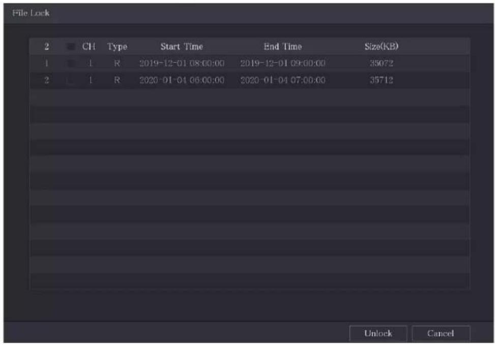
5.10 Alarm Events Settings
5.10.1 Alarm Information
You can search, view and back up the alarm information.
Step 1 Select Main Menu > ALARM > Alarm Info.
Figure 5-124 Alarm info
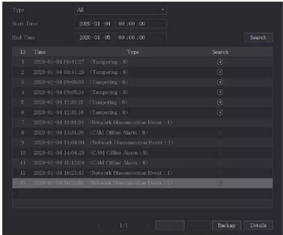
Step 2 In the Type list, select the event type; In the Start Time box and End Time box, enter the specific time.
Step 3 Click Search.
The search results are displayed.
Step 4 Click Backup to back up the search results into the external storage device.

- Click 🎯 to play the recorded video of alarm event.
- Select an event and click Details to view the detailed information of the event.
5.10.2 Alarm Input Settings
Connect the alarm input and output ports by referring to "4.3 Connecting to Alarm Input and Output". You can configure the alarm settings for each channel individually or apply the settings to all channels and then save the settings.
5.10.2.1 Configuring Local Alarms
You can connect the alarm device to the alarm input port of the Device. When the alarm is activated on the alarm device, the alarm information will be uploaded to the Device, and then the Device outputs the local alarms in the way that you configure in this section.
Step 1 Select Main Menu > ALARM > Alarm-in Port > Local.
Figure 5-125 Local page
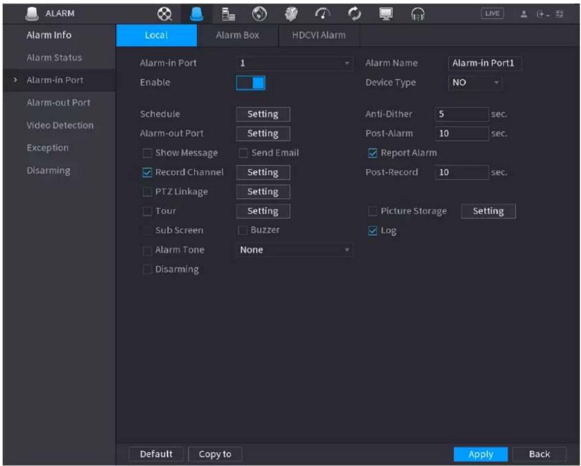
Step 2 Configure the settings for the local alarms.
Table 5-27 Local alarm settings
| Parameter Description | |
| Alarm-in Port | Select the channel number. |
| Alarm Name | Enter the customized alarm name. |
| Enable | Enable or disable the local alarm function. |
| Device Type | In the Device Type list, select NO or select NC as the voltage output type. |
| Schedule | Click Setting to display setting interface.Define a period during which the motion detection is active. For details, see "Setting Motion Detection Period" section in "5.10.4.1 Configuring Motion Detection Settings". |
| Anti-Dither | Configure the time period from end of event detection to the stop of alarm. |
| Alarm-out Port | ClickSettingto configure the parameters.Local Alarm: Enable alarm activation through the alarm devices connected to the selected output port.Extension Alarm: Enable alarm activation through the connected alarm box.Wireless Siren: Enable alarm activation through devices connected by USB gateway or camera gateway. |
| Post-Alarm | Set a length of time for the Device to delay turning off alarm after the external alarm is cancelled. The value ranges from 0 seconds to 300 seconds, and the default value is 10 seconds. |
| Show Message | Select theShow Messagecheckbox to enable a pop-up message in your local host PC. |
| Report Alarm | Select theReport Alarmcheckbox to enable the system to upload the alarm signal to the network (including alarm center) when an alarm event occurs. |
| Send Email | Select theSend Emailcheckbox to enable the system to send an email notification when an alarm event occurs.To use this function, make sure the email function is enabled inMain Menu > NETWORK > Email. |
| Record Channel | Select the channel(s) that you want to record. The selected channel(s) starts recording after an alarm event occurs.The recording for local alarm recording and auto recording must be enabled. For details, see "5.1.4.9 Configuring Recorded Video Storage Schedule" and "5.9.1 Enabling Record Control". |
| PTZ Linkage | ClickSettingto display the PTZ page.Enable PTZ linkage actions, such as selecting the preset that you want to be called when an alarm event occurs. |
| Post Record | Set a length of time for the Device to delay turning off recording after the alarm is cancelled. The value ranges from 10 seconds to 300 seconds, and the default value is 10 seconds. |
| Tour | Select theTourcheckbox to enable a tour of the selected channels. |
| Picture Storage | Select theSnapshotcheckbox to take a snapshot of the selected channel.To use this function, selectMain Menu > CAMERA > Encode > Snapshot, in theType list, selectEvent. |
| Sub Screen | Select the checkbox to enable the function. When an alarm event occurs, the extra screen outputs the settings configured inMain Menu > DISPLAY > Tour Setting > Sub Screen.This function is available on select models.To use this function, extra screen shall be enabled. |
| Video Matrix | Select the checkbox to enable the function. When an alarm event occurs, the video output port outputs the settings configured inMain Menu > DISPLAY > Tour Setting.This function is available on select models. |
| Buzzer | Select the checkbox to activate a buzzer noise at the Device. |
| Log | Select the checkbox to enable the Device to record a local alarm log. |
| Disarming | After enabling this function, you can connect a switch to the alarm input port for disarming control. |
Step 3 Click Apply to complete the settings.

- Click Default to restore the default setting.
- Click Copy to, in the Copy to dialog box, select the additional channel(s) that you want to copy the local alarm settings to, and then click Apply.
5.10.2.2 Configuring Alarms from Alarm Box
You can connect the alarm box to the RS-485 port of the Device. When the alarm is detected by the alarm box, the alarm information will be uploaded to the Device, and then the Device outputs the alarms in the way that you configure in this section.
Step 1 Select Main Menu > ALARM > Alarm-in Port > Alarm Box.
Figure 5-126 Alarm box
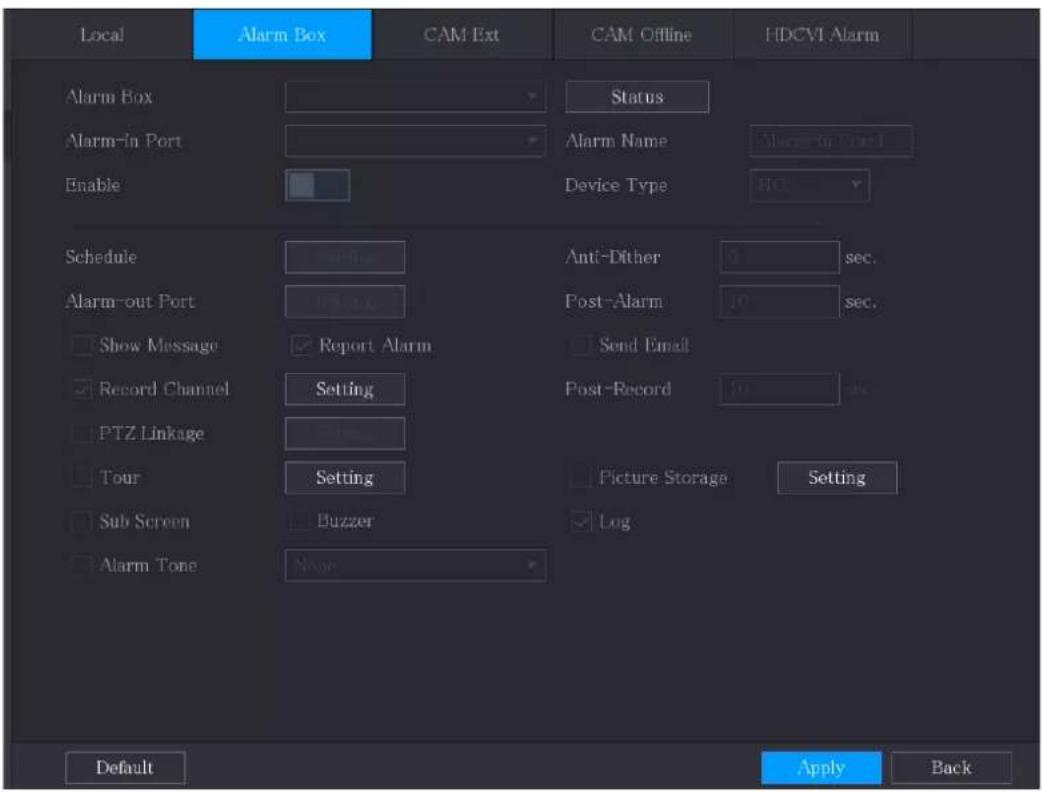
Step 2 In the Alarm Box list, select the alarm box number corresponding to the address number configured by the DIP switch on the Alarm Box.
Step 3 In the Alarm-in Port list, select the alarm input port on the Alarm Box.
Step 4 Configure the settings for other parameters of the Alarm Box.
Step 5 Click Apply to complete the settings.

Click Default to restore the default setting.
5.10.2.3 Configuring Alarms from External IP Cameras
Step 1 Select Main Menu > ALARM > Alarm-in Port > CAM Ext.
Figure 5-127 CAM ext
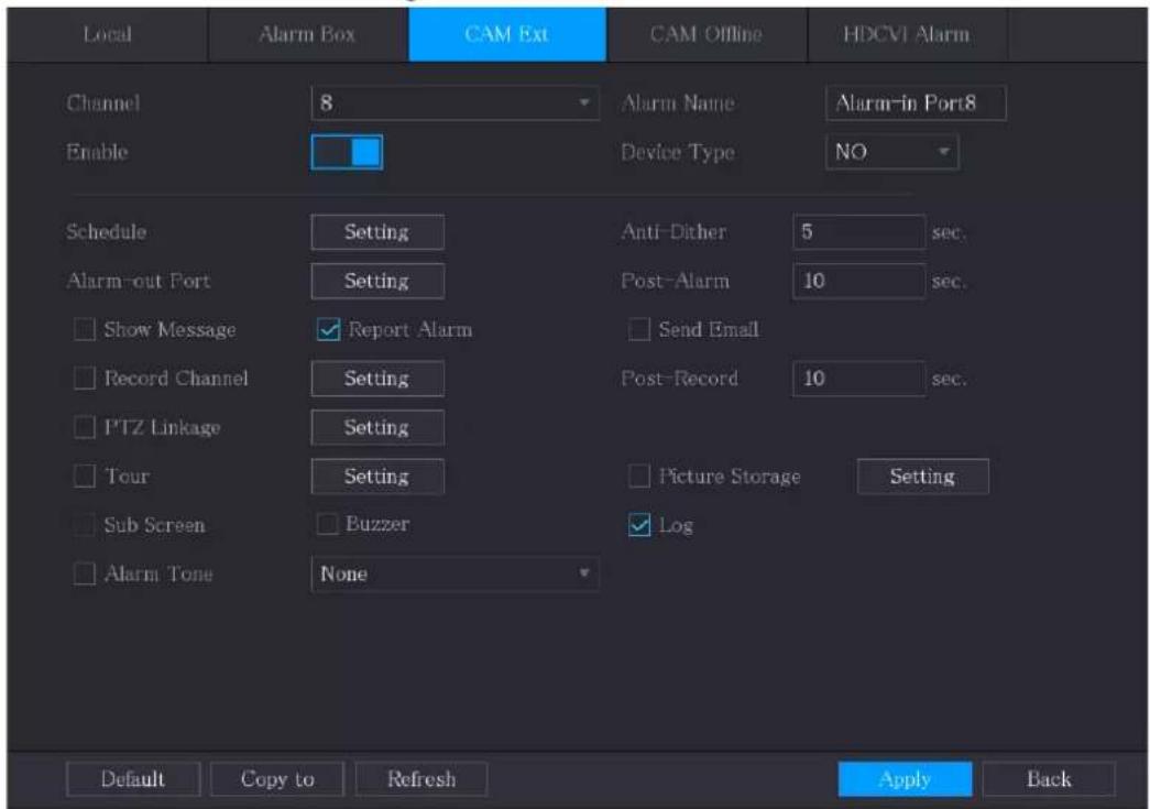
Step 2 Configure the alarm input settings from the external IPC.
Step 3 Click Apply to complete the settings.

- Click Default to restore the default setting.
- Click Copy to copy the settings to other channels.
- Click Refresh to refresh configured settings.
5.10.2.4 Configuring Alarms for IP Camera Offline
You can configure the alarm settings for the situation when the IP camera is offline.
Step 1 Select Main Menu > ALARM > Alarm-in Port > CAM Offline.
Figure 5-128 CAM offline
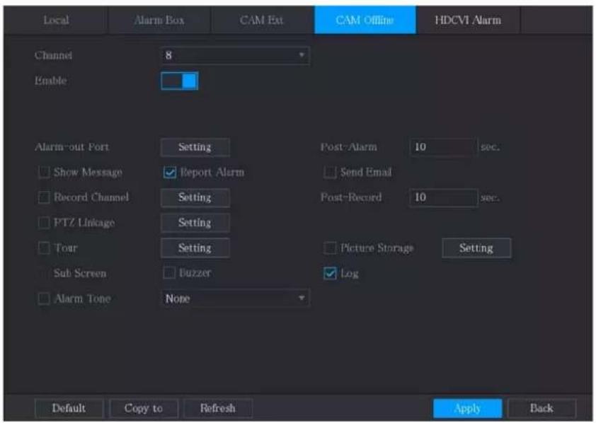
Step 2 Configure the alarm input settings from the offline IPC.
Step 3 Click Apply to complete the settings.

- Click Default to restore the default setting.
- Click Copy to copy the settings to other channels.
5.10.2.5 Configuring Alarms from HDCVI Devices
Step 1 Select Main Menu > ALARM > Alarm-in Port > HDCVI Alarm.
Figure 5-129 HDCVI alarm
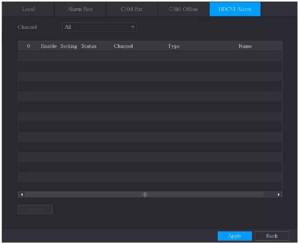
Step 2 In the Channel list, select a channel or All.
Step 3 Click.

Step 4 Configure the settings for other parameters of the Alarm Box.
Step 5 Click OK to save the settings.
Step 6 Click Apply to complete the settings.
5.10.3 Alarm Output Settings
5.10.3.1 Configuring Alarm Output
When the Device activates alarms, the connected alarm device generates alarms in the way that you can configure in this section. You can connect to the output port of the Device or connect wirelessly.
- Auto: When an alarm event is triggered on the Device, the connected alarm device generates alarms.
- Manual: The alarm device is forced to keep generating alarms.
- Stop: The alarm output function is not enabled.
Step 1 Select Main Menu > ALARM > Alarm-out Port > Alarm Mode.
Figure 5-130 Alarm mode
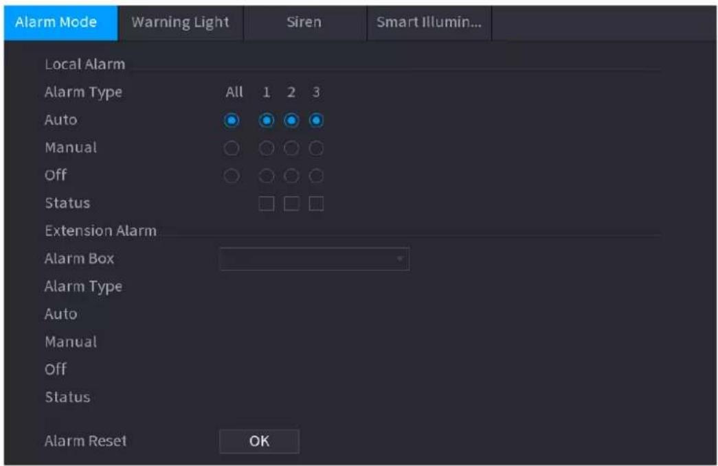
Step 2 Configure the settings for the alarm output.
Table 5-28 Alarm output settings
| Parameter | Description | |
| Local Alarm | Alarm Type | Select alarm type for each alarm output port. |
| Status | Indicates the status of each alarm output port. | |
| Extension Alarm | Alarm Box | Select the alarm box number corresponding to the address number configured by the DIP switch on the Alarm Box. |
| Alarm Type | Select the alarm type for each alarm output ports. | |
| Status | Indicates the status of each alarm output port. | |
| Alarm Reset | Click OK to clear all alarm output status. | |
Step 3 Click Apply to save the settings.
5.10.3.2 Configuring Warning Light
When the motion detection alarm is activated, the system links the camera to generate warning light alarm.

To use this function, connect at least one warning light camera to your Device.
Step 1 Select Main Menu > ALARM > Alarm-out Port > Warning Light.
Figure 5-131 Warning light
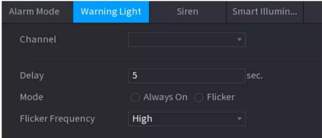
Step 2 Configure the settings for the warning light parameters.
Table 5-29 Warning light parameters
| Parameter Description | |
| Channel | In the Channel list, select a channel that is connected to a warning light camera. |
| Delay | Set a length of time for the Device to delay turning off alarm after the alarm is cancelled. The value ranges from 5 seconds to 30 seconds, and the default value is 5 seconds. |
| Mode | Set the alarm mode of warning light to be Always on or Flicker. |
| Flicker Frequency | When setting the alarm mode of warning light to be Flash, you can select the flash frequency from Low, Middle, and High. |
Step 3 Click Apply to complete the settings.
5.10.3.3 Configuring Siren
When the motion detection alarm is activated, the system links the camera to generate sound alarm.

To use this function, connect at least one camera that supports audio function.
Step 1 Select Main Menu > ALARM > Alarm-out Port > Siren.
Figure 5-132 Siren
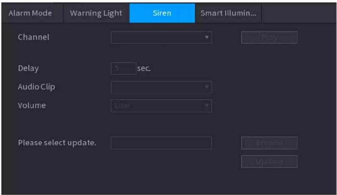
Step 2 Configure the settings for the siren parameters.
Table 5-30 Siren parameters
| Parameter Description | |
| Channel | In the Channel list, select a channel that is connected to a camera that supports audio function. |
| Play | Click Play to manually trigger the IP camera to play audio file. |
| Delay | Set a length of time for the Device to delay turning off alarm after the alarm is cancelled. The value ranges from 5 seconds to 30 seconds, and the default value is 5 seconds. |
| Audio Clip | Select the audio clip for the siren sound. The default setting is Clip 1. |
| Volume | Select the volume for the audio clip. You can select the flash frequency from Low, Middle, and High. |
| Update Audio Clip | Import the upgrade audio file (.bin or .wav) to upgrade the alarm audio file of the camera. |
Step 3 Click Apply to complete the settings.
Related Operations
You can update the audio files of the camera on the local interface.
- Prepare a USB device or other external storage device and plug it into the Device.
- Click Browse.
- Select the upgrade audio file (.bin or .wav).
- Click OK to return to the Siren page.
- Click Upgrade to upgrade the alarm audio file of the camera.
Figure 5-133 Browse
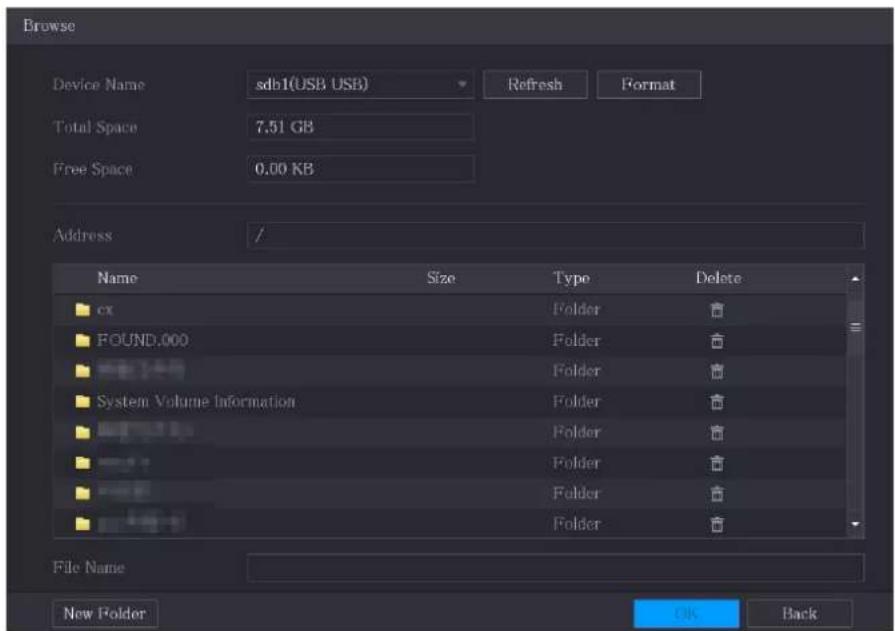
5.10.3.4 Configuring Smart Illumination
The linkage action of smart illumination can extend for a period after the event ends.

To use this function, connect a camera that supports smart illumination.
Step 1 Select Main Menu > ALARM > Alarm-out Port > Smart Illumination.
Figure 5-134 Smart illumination
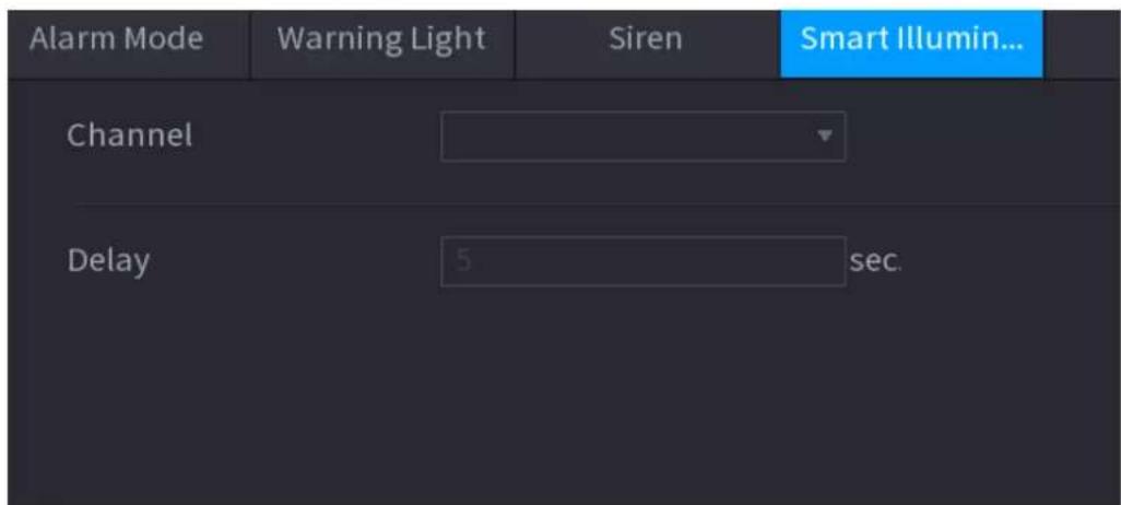
Step 2 Select a channel and then set the delay time.
Step 3 Click Apply.
The illuminator remains on during the delay period after the linked event ends.
5.10.4 Video Detection
Video detection adopts computer vision and image processing technology. The technology analyzes the video images to detect the obvious changes such as moving objects and blurriness. The system activates alarms when such changes are detected.
5.10.4.1 Configuring Motion Detection Settings
When the moving object appears and moves fast enough to reach the preset sensitivity value, the system activates the alarm.
Step 1 Select Main Menu > ALARM > Video Detection > Motion Detection.
Figure 5-135 Motion
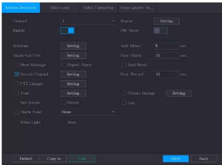
Step 2 Configure the settings for the motion detection parameters.
Table 5-31 Motion detection parameters
| Parameter Description | |
| Channel | In the Channel list, select a channel to set the motion detection. |
| Region | Click Setting to define the motion detection region. |
| Enable Enable or disable | the motion detection function. |
| PIR Alarm | PIR function helps enhancing the accuracy and validity of motion detect. It can filter the meaningless alarms that are activated by the objects such as falling leaves, flies. The detection range by PIR is smaller than the field angle.PIR function is enabled by default if it is supported by the cameras. Enabling PIR function will get the motion detect to be enabled automatically to generate motion detection alarms; if the PIR function is not enabled, the motion detect just has the general effect.Only when the channel type is CVI, the PIR function can be enabled.If the camera does not support PIR function, it will be unusable.If the Device does not support PIR function, it will not be displayed on the page. |
| Schedule | Define a period during which the motion detection is active. |
| Anti-Dither | Configure the time period from end of event detection to the stop of alarm. |
| Alarm-out Port | ClickSettingto configure the parameters.General Alarm: Enable alarm activation through the alarm devices connected to the selected output port.External Alarm: Enable alarm activation through the connected alarm box.Wireless Siren: Enable alarm activation through devices connected by USB gateway or camera gateway. |
| Post-Alarm | Set a length of time for the Device to delay turning off alarm after the external alarm is cancelled. The value ranges from 0 seconds to 300 seconds, and the default value is 10 seconds. If you enter 0, there will be no delay. |
| Show Message | Select theShow Messagecheckbox to enable a pop-up message in your local host PC. |
| Report Alarm | Select theReport Alarmcheckbox to enable the system to upload the alarm signal to the network (including alarm center) when an alarm event occurs. |
| Send Email | Select theSend Emailcheckbox to enable the system to send an email notification when an alarm event occurs.To use this function, make sure the email function is enabled inMainMenu > NETWORK > Email. |
| Record Channel | Select the channel(s) that you want to record. The selected channel(s) starts recording after an alarm event occurs.The recording for motion detection and auto recording function must be enabled. For details, see "5.1.4.9 Configuring Recorded Video Storage Schedule" and "5.9.1 Enabling Record Control". |
| PTZ Linkage | ClickSettingto display the PTZ page.Enable PTZ linkage actions, such as selecting the preset that you want to be called when an alarm event occurs.Motion Detect can only activate PTZ preset. |
| Post Record | Set a length of time for the Device to delay turning off recording after the alarm is cancelled. The value ranges from 10 seconds to 300 seconds, and the default value is 10 seconds. |
| Tour | Select theTourcheckbox to enable a tour of the selected channels. |
| Picture Storage | Select theSnapshotcheckbox to take a snapshot of the selected channel.To use this function, selectMain Menu>CAMERA>Encode>Snapshot,in theTypelist, selectEvent. |
| Sub Screen | Select the checkbox to enable the function. When an alarm event occurs, the extra screen outputs the settings configured inMain Menu>DISPLAY>Tour>Sub Screen.This function is available on select models.To use this function, extra screen shall be enabled. |
| Video Matrix | Select the checkbox to enable the function. When an alarm event occurs, the video output port outputs the settings configured inMain Menu>DISPLAY>Tour.This function is available on select models. |
| Buzzer | Select the checkbox to activate a buzzer noise at the Device. |
| Log | Select the checkbox to enable the Device to record a local alarm log. |
| Alarm Tone | Select to enable audio broadcast/alarm tones in response to a motion detection event. |
| Warning Light | Select the checkbox to enable warning light alarm of the camera. |
| Siren | Select the checkbox to enable sound alarm of the camera. |
Step 3 Click Apply to save the settings.

- Click Default to restore the default setting.
- Click Copy to, in the Copy to dialog box, select the additional channel(s) that you want to copy the motion detection settings to, and then click Apply.
- Click Test to test the settings.
Setting the Motion Detection Region
Step 1 Next to Region, click Setting.
Step 2 Point to the middle top of the page.
Figure 5-136 Detection setting
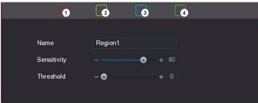
Step 3 Configure the regions settings. You can configure totally four regions.
1) Select one region, for example, click

2) Drag on the screen to select the region that you want to detect. The selected area shows the color that represents the region.
3) Configure the parameters.
Table 5-32 Motion detection parameters
| Parameter Description | |
| Name Enter a name for the region. | |
| Sensitivity | Every region of every channel has an individual sensitivity value.The bigger the value is, the easier the alarms can be activated. |
| Threshold | Adjust the threshold for motion detect. Every region of every channel has an individual threshold. |

When anyone of the four regions activates motion detect alarm, the channel where this region belongs to will activate motion detect alarm.
Step 4 Right-click on the screen to exit the region setting page.
Step 5 On the Motion Detection page, click Apply to complete the settings.
Setting Motion Detection Period

The system only activates the alarm in the defined period.
Step 1 Next to Schedule, click Setting.
Figure 5-137 Setting
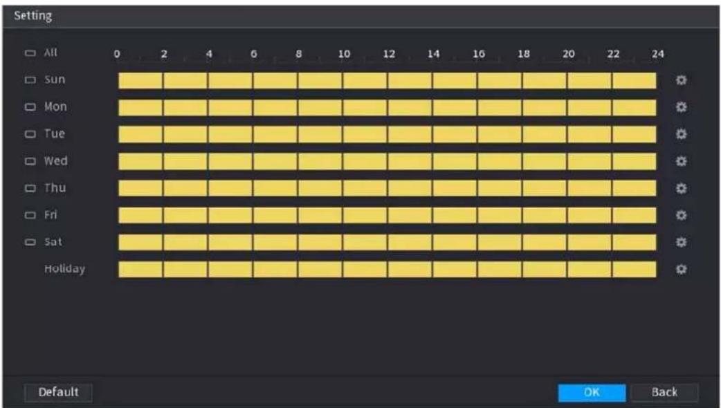
Step 2 Define the motion detection period. By default, it is active all the time.
- Define the period by drawing.
Define for a specified day of a week: On the timeline, click the half-hour blocks to select the active period.
Define for several days of a week: Click before each day, the icon switches to
. On the timeline of any selected day, click the half-hour b active periods, all the days with will take the same settings.
Define for all days of a week: Click All, all switches to On the timeline of any day, click the half-hour blocks to select the active periods, all the days will take the same settings.
- Define the period by editing. Take Sunday as an example.
1) Click
Figure 5-138 Period
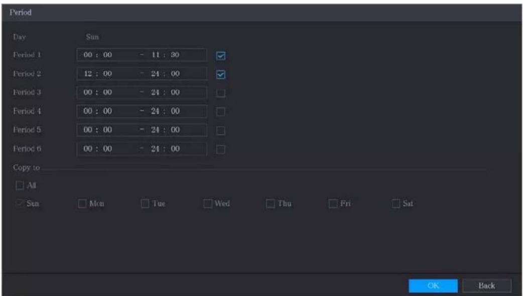
2) Enter the time frame for the period, and then select the checkbox to enable the settings.
◇ There are six periods for you to set for each day.
Under Copy to, select All to apply the settings to all the days of a week, or select specific day(s) that you want to apply the settings to.
3) Click OK to save the settings.
Step 3 On the Motion Detection page, click Apply to complete the settings.
5.10.4.2 Configuring Video Loss Settings
When the video loss occurs, the system activates the alarm.
Step 1 Select Main Menu > ALARM > Video Detection > Video Loss.
Figure 5-139 Video loss
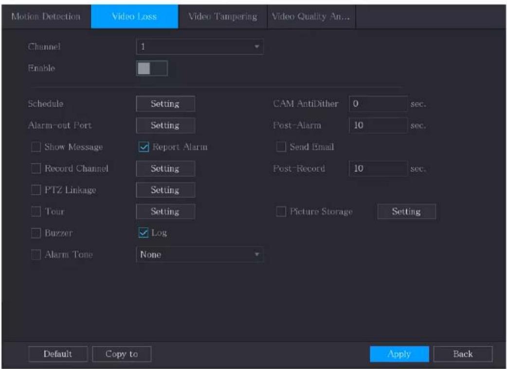
Step 2 To configure the settings for the video loss detection parameters, see "5.10.4.1 Configuring Motion Detection Settings".

For PTZ activation, different from motion detection, the video loss detection can activate PTZ preset, tour, and pattern.
Step 3 Click Apply to complete the settings.

- Click Default to restore the default setting.
- Click Copy to, in the Copy to dialog box, select the additional channel(s) that you want to copy the motion detection settings to, and then click Apply.
5.10.4.3 Configuring Tampering Settings
When the camera lens is covered, or the video is displayed in a single color because of the causes such as sunlight status, the monitoring cannot be continued normally. To avoid such situations, you can configure the tampering alarm settings.
Step 1 Select Main Menu > ALARM > Video Detection > Video Tampering.
Figure 5-140 Video tampering
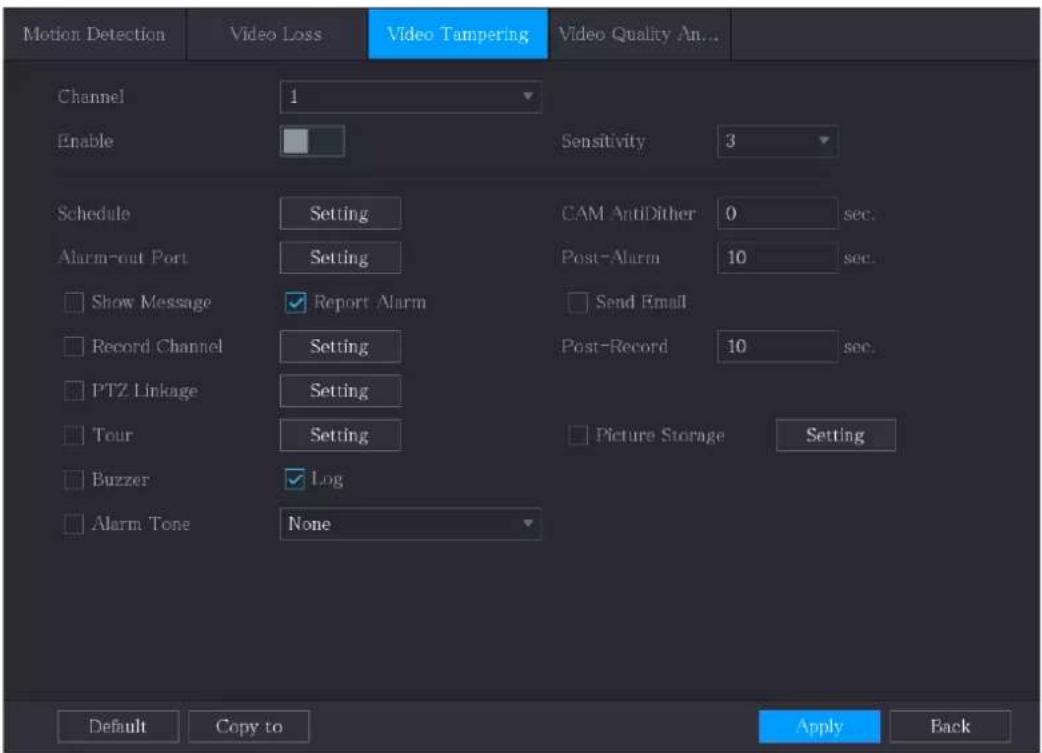
Step 2 To configure the settings for the tampering detection parameters, see "5.10.4.1 Configuring Motion Detection Settings".

For PTZ activation, different from motion detection, the video loss detection can activate PTZ preset, tour, and pattern.
Step 3 Click Apply to complete the settings.

- Click Default to restore the default setting.
- Click Copy to, in the Copy to dialog box, select the additional channel(s) that you want to copy the motion detection settings to, and then click Apply.
5.10.5 System Events
You can configure the alarm output for three types of system event (HDD, Network, and User). When there is an abnormal system event occurs, the system activates alarms in the way that you configure in this section.
5.10.5.1 Configuring HDD Event Settings
Step 1 Select Main Menu > ALARM > Exception > Disk.
Figure 5-141 Disk
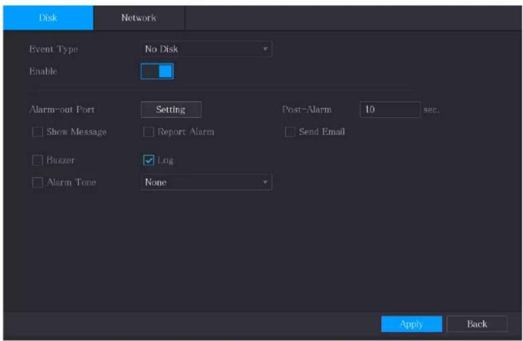
Step 2 Configure the settings for the HDD event.
Table 5-33 HDD event settings
| Parameter Description | |
| Event Type | In the Event Type list, select No Disk, Disk Error, or Low Space as the event type. |
| Enable | Enable or disable the HDD event detection function. |
| Alarm-out Port | Click Setting to configure the parametersLocal Alarm: Enable alarm activation through the alarm devices connected to the selected output port.Extension Alarm: Enable alarm activation through the connected alarm box.Wireless Siren: Enable alarm activation through devices connected by USB gateway or camera gateway. |
| Post-Alarm | Set a length of time for the Device to delay turning off alarm after the external alarm is cancelled. The value ranges from 10 seconds to 300 seconds, and the default value is 10 seconds. |
| Show Message | Select the Show Message checkbox to enable a pop-up message in your local host PC. |
| Report Alarm | Select the Report Alarm checkbox to enable the system to upload the alarm signal to the network (including alarm center) when an alarm event occurs. |
| Send Email | Select the Send Email checkbox to enable the system to send an email notification when an alarm event occurs.To use this function, make sure the email function is enabled in Main Menu > NETWORK > Email. |
| Buzzer | Select the checkbox to activate a buzzer noise at the Device. |
| Log | Select the checkbox to enable the Device to record a local alarm log. |
| Alarm Tone | Select to enable audio broadcast/alarm tone in response to a HDD alarm event. |
Step 3 Click Apply to complete the settings.
5.10.5.2 Configuring Network Event Settings
Step 1 Select Main Menu > ALARM > Exception > Network.
Figure 5-142 Network
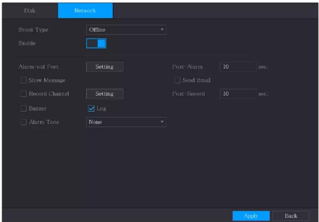
Step 2 Configure the settings for the Network event.
Table 5-34 Network event settings
| Parameter Description | |
| Event Type | In the Event Type list, select Office, IP Conflict, or MAC Conflict as the event type. |
| Enable | Enable or disable the Network event detection function. |
| Alarm-out Port | Click Setting to configure the parameters.General Alarm: Enable alarm activation through the alarm devices connected to the selected output port.External Alarm: Enable alarm activation through the connected alarm box.Wireless Siren: Enable alarm activation through devices connected by USB gateway or camera gateway. |
| Post-Alarm | Set a length of time for the Device to delay turning off alarm after the external alarm is cancelled. The value ranges from 10 seconds to 300 seconds, and the default value is 10 seconds. |
| Parameter Description | |
| Show Message | Select the Show Message checkbox to enable a pop-up message in your local host PC. |
| Send Email | Select the Send Email checkbox to enable the system to send an email notification when an alarm event occurs.To use this function, make sure the email function is enabled in Main Menu > NETWORK > Email. |
| Buzzer | Select the checkbox to activate a buzzer noise at the Device. |
| Log | Select the checkbox to enable the Device to record a local alarm log. |
| Post Record | Continue to record for some time after the alarm is ended. The value ranges from 10 seconds to 300 seconds. |
| Alarm Tone | Select to enable audio broadcast/alarm tones in response to a network alarm event. |
Step 3 Click Apply to complete the settings.
5.10.6 Configuring Disarming
You can disarm all alarm linkage actions as needed.
Step 1 Select Main Menu > ALARM > Disarming.
Step 2 Click to enable disarming.
Figure 5-143 Disarming
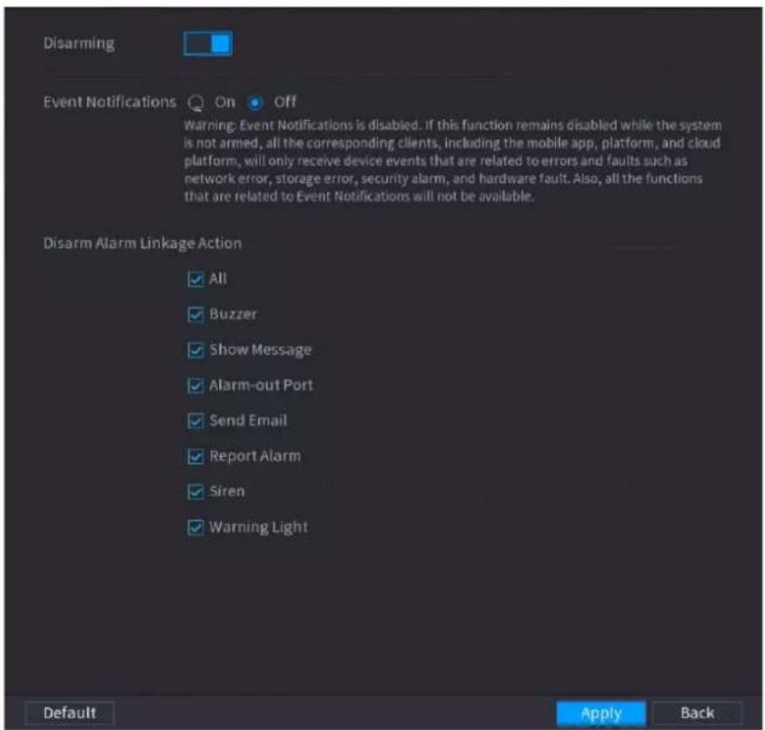
Step 3 (Optional) Select Off to disable event notifications.
With Disarming enabled, if you disable event notifications, event notifications will not be pushed to the clients including the mobile app, platform and cloud platform.
Step 4 Select alarm linkage actions to disarm.

All alarm linkage actions will be disarmed when you select All.
Step 5 Click Apply.
5.11 AI Function
5.11.1 Configuring AI Mode
To use AI functions, you need to enable the corresponding AI mode.
Step 1 Select Main Menu > AI > Parameters > AI Mode.
Figure 5-144 AI mode
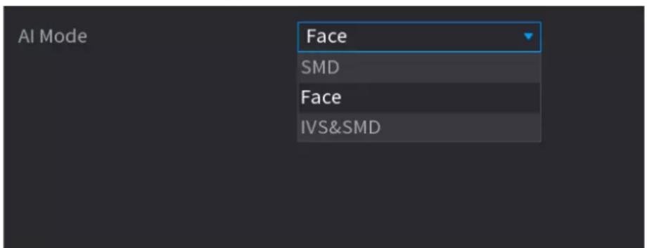
Step 2 Select an AI mode
- When SMD is selected, only SMD is available.
- When Face is selected, only face detection and face recognition are available.
- When IVS&SMD is selected, only IVS and SMD are available.

SMD, face detection, face recognition and IVS cannot be enabled simultaneously.
5.11.2 For Pro AI Series

The faces are fuzzily processed to comply with relevant regulations.
AI module provides face detection, face recognition, IVS functions, and video structuring. These functions take effect after they are configured and enabled. It adopts deep learning and can realize precision alarms.
- Face detection: The Device can analyze the faces captured by the camera and link the configured alarms.
- Face recognition: The Device can compare the captured faces with the face database and then link the configured alarms.
- IVS: The IVS function processes and analyzes the human and vehicle images to extract the key information to match with the preset rules. When the detected behaviors match with the rules,
the system activates alarms. The IVS function can avoid wrong alarms by filtering the factors such as rains, light, and animals.
- Video structuring: The device can detect and extract key features from the human bodies and non-motor vehicles in the video, and then build a structured database. You can search any target you need with these features. For example, you can search any people who wears yellow short sleeve shirt. See more details in "5.11.1.4 Video Structuring".
5.11.2.1 Face Detection
The Device can analyze the pictures captured by the camera to detect whether the faces are on the pictures. You can search and filter the recorded videos the faces and play back.

If you select AI by device, then among face detection and recognition, IVS function, and video structuring, you can use one of them at the same time for the same channel.
5.11.2.1.1 Configuring Face Detection Parameters
The alarms are generated according to the configured parameters.
Step 1 Main Menu > AI > Parameters > Face Detection.
Figure 5-145 Face detection
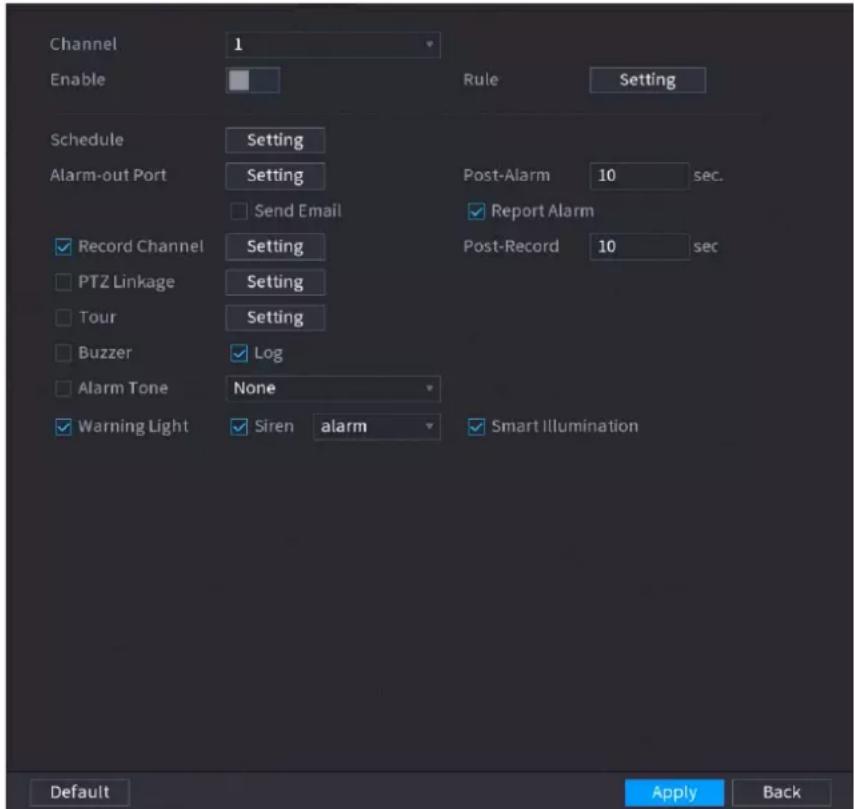
Step 2 In the Channel list, select a channel that you want to configure face detection function, and then enable it.
Step 3 Configure the parameters.
Table 5-35 Face detection parameters
| Parameter Description | |
| Type | You can select from AI by Camera and AI by Device.Al by Camera: This option requires certain AI cameras. The camera will do all the AI analysis, and then give the results to the DVR.Al by Device: The camera only transmits normal video stream to the DVR, and then the DVR will do all the AI analysis. |
| Rule | Click View Setting to draw areas to filter the target.You can configure two filtering targets (maximum size and minimum size). When the target is smaller than the minimum size or larger than the maximum size, no alarms will be activated. The maximum size should be larger than the minimum size. |
| Schedule | Define a period during which the detection is active.For details, see "Setting Motion Detection Period" section in "5.10.4.1 Configuring Motion Detection Settings". |
| Alarm-out Port | Click Setting to configure the parameters.General Alarm: Enable general alarm and select the alarm output port.Ext. Alarm: Connect the alarm box to the Device and then enable it.Wireless Siren: Connect the wireless gateway to the Device and then enable it. For details, see "5.12 IoT Function".When an alarm event occurs, the system links the peripheral alarm devices connected to the selected output port. |
| Post-Alarm | Set a length of time for the Device to delay turning off alarm after the external alarm is cancelled. The value ranges from 0 seconds to 300 seconds. If you enter 0, there will be no delay. |
| Show Message | Select the Show Message checkbox to enable a pop-up alarm message in your local host PC. |
| Report Alarm | Select the Report Alarm checkbox to enable the system to upload the alarm signal to the network (including alarm center) when an alarm event occurs.This function is available on select models.The corresponding parameters in the alarm center should be configured. For details, see "5.15.1.12 Configuring Alarm Center Settings". |
| Send Email | Select the Send Email checkbox to enable the system to send an email notification when an alarm event occurs.To use this function, make sure the email function is enabled in Main Menu > NETWORK > Email. |
| Record Channel | Select the channel(s) that you want to record. The selected channel(s) starts recording after an alarm event occurs.The recording for intelligence event and auto recording function must be enabled. For details, see "5.1.4.9 Configuring Recorded Video Storage Schedule" and "5.9.1 Enabling Record Control". |
| PTZ Linkage | ClickSettingto display the PTZ page.Enable PTZ linkage actions, such as selecting the preset that you want to be called when an alarm event occurs.To use this function, the PTZ operations must be configured. For details, see "5.4 Controlling PTZ Cameras". |
| Post Record | Set a length of time for the Device to delay turning off recording after the alarm is cancelled. The value ranges from 10 seconds to 300 seconds. |
| Tour | Select the Tourcheckbox to enable a tour of the selected channels.To use this function, the tour setting must be configured.After the tour is ended, the live view screen returns to the view layout before tour started. |
| Picture Storage | Select thePicture Storagecheckbox to take a snapshot of the selected channel.To use this function, make sure the snapshot function is enabled forIntelinMain Menu >STORAGE>Schedule>Snapshot. |
| Video Matrix | Select the checkbox to enable the function. When an alarm event occurs, the video output port outputs the settings configured inMain Menu >DISPLAY >TOUR >Extra Screen.This function is available on select models.The extra screen must be enabled to support this function. |
| Buzzer | Select the checkbox to activate a buzzer noise at the Device. |
| Log | Select the checkbox to enable the Device to record a local alarm log. |
| Alarm Tone | Select to enable audio broadcast in response to a face detection event. |
| Warning Light | Select the checkbox to enable the warning light alarm of the camera. |
| Siren | Select the checkbox to enable the sound alarm of the camera. |
| Smart Illumination | Select the checkbox to enable the smart illumination of the camera. |
Step 4 Click Apply to complete the settings.
5.11.2.1.2 Searching for and Playing Detected Faces
You can search the detected faces and play back.
Step 1 Select Main Menu > AI > AI Search > Face Detection.
Figure 5-146 Face detection
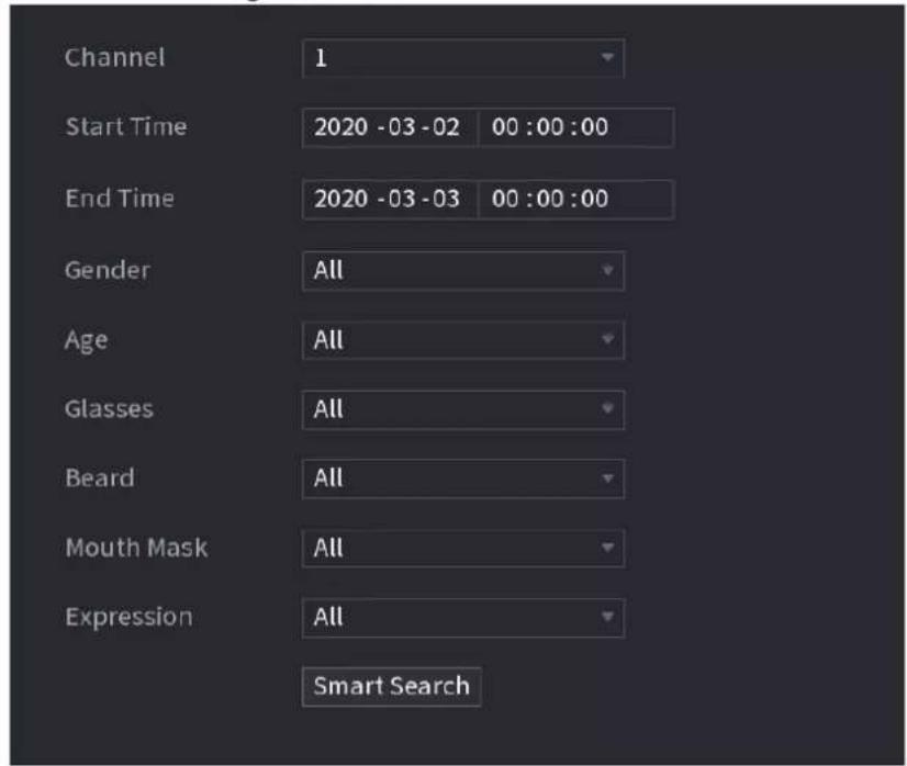
Step 2 Select the channel, enter the start time and end time, and set for the gender, age, glasses, beard, and mask.
Step 3 Click Smart Search.
The results are displayed.
Figure 5-147 Search results
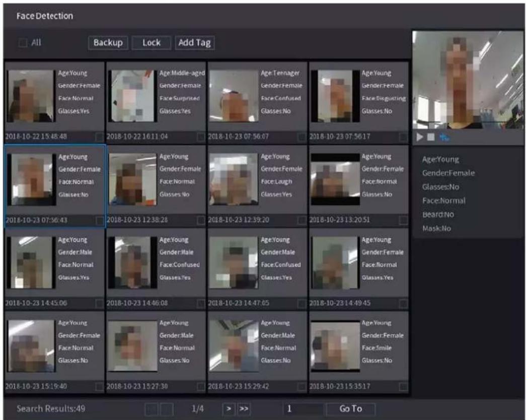
Step 4 Select the face that you want to play back.
Figure 5-148 Registered information
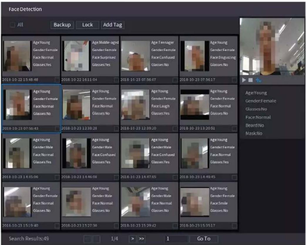
Step 5
Click ▶ to start playing back the recorded detected face snapshots.

Double-click on the playing page to switch between full screen playing and thumbnail playing.
You can also do the following operations to the recorded files.
- To export the database file (.csv) to the external storage device, select files, click Export, and then select the save path.
- To back up the recorded files to the external storage device, select files, click Backup, select the save path and file type, and then click Start.
Figure 5-149 Backup
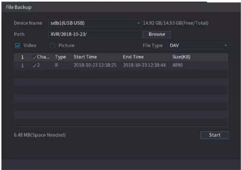
- To lock the files to make it unable to be overwritten, select the files, and then click Lock.
• To add a mark to the file, select the files and then click Add Tag.
5.11.2.2 Face Recognition
Face recognition applies to AI preview mode and smart search.
- AI preview mode: Supports comparing the detected faces with the face database, and display the comparison results.
• Smart search: Supports faces searching by faces attributes or portraits.

- If you select AI by device, then among face detection and recognition, IVS function, and video structuring, you can use one of them at the same time for the same channel.
- Before enabling face recognition function for a channel, the face detection must be enabled first for this channel.
5.11.2.2.1 Face Database Management
You should create a face database for comparing the detected faces and the faces in the database. The Device supports creating maximum 20 databases and registering 100,000 faces.
Creating a Face Database
Step 1 Select Main Menu > AI > Database > Face Database Config.
Figure 5-150 Face database configuration
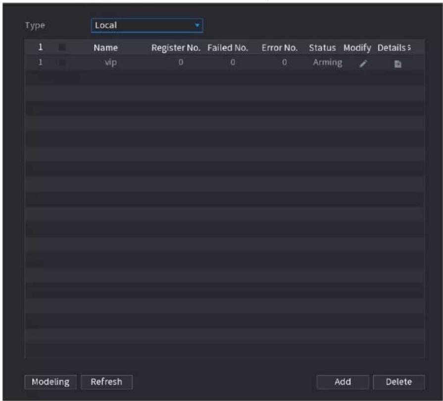
Step 2 At Type, you can select Local or Remote.
- Local: Viewing the existing face databases or adding new one on the DVR.
- Remote: If you have face recognition camera, you can select this to view the existing face databases or adding new one on the camera.
Step 3 Click Add.
Figure 5-151 Add face database
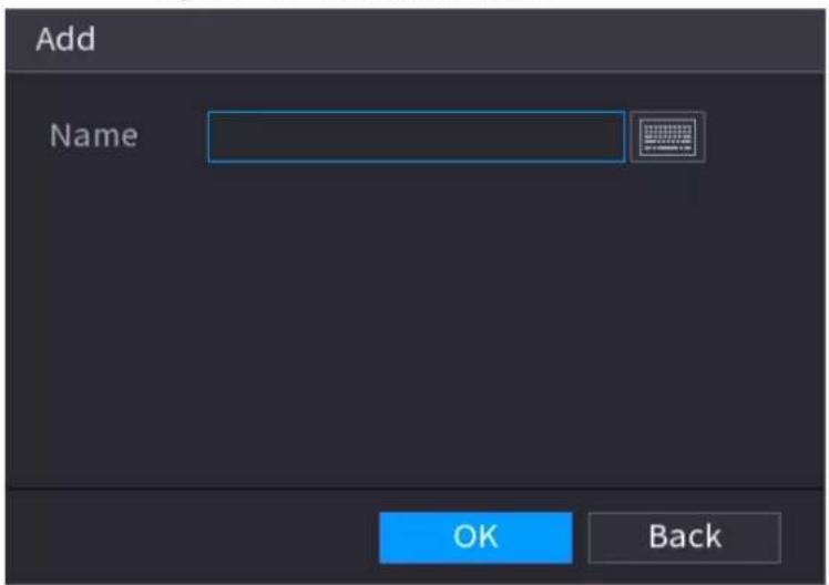
Step 4 Enter the face database name, and then click OK.
- Click to modify database name.
- Click to view the database details and add new faces to the database.
- Select the database, and then click Modeling. The system will extract the attributes of face pictures in the database for the future comparison.
- Select the database, and then click Delete to delete the database.
Figure 5-152 Configure database
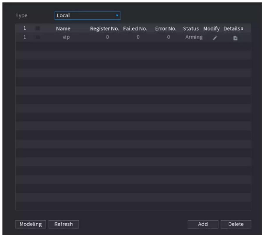
Adding Face Pictures
You can add face pictures to the existing databases one by one or by batch, or add from the detected faces.

To add face pictures one by one or by batch, you need to get the pictures from the USB storage device. The picture size should be smaller than 256K with resolution between 200 × 200–6000 × 5000.
Adding One Face Picture
Step 1 Select Main Menu > AI > Database > Face Database Config.
of the database that you want to configure.
Figure 5-153 Details
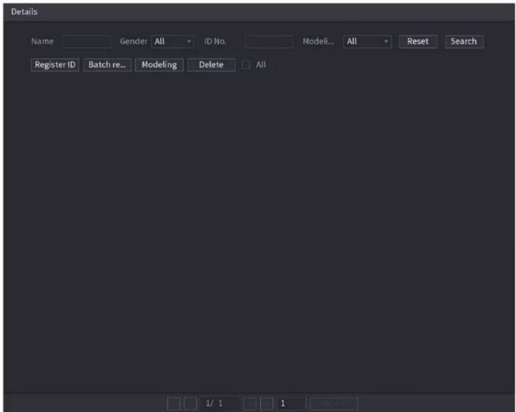
Step 3 Click Register ID.
Figure 5-154 Register ID
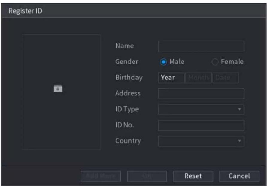
Step 4 Click to add a face picture.
Figure 5-155 Browse
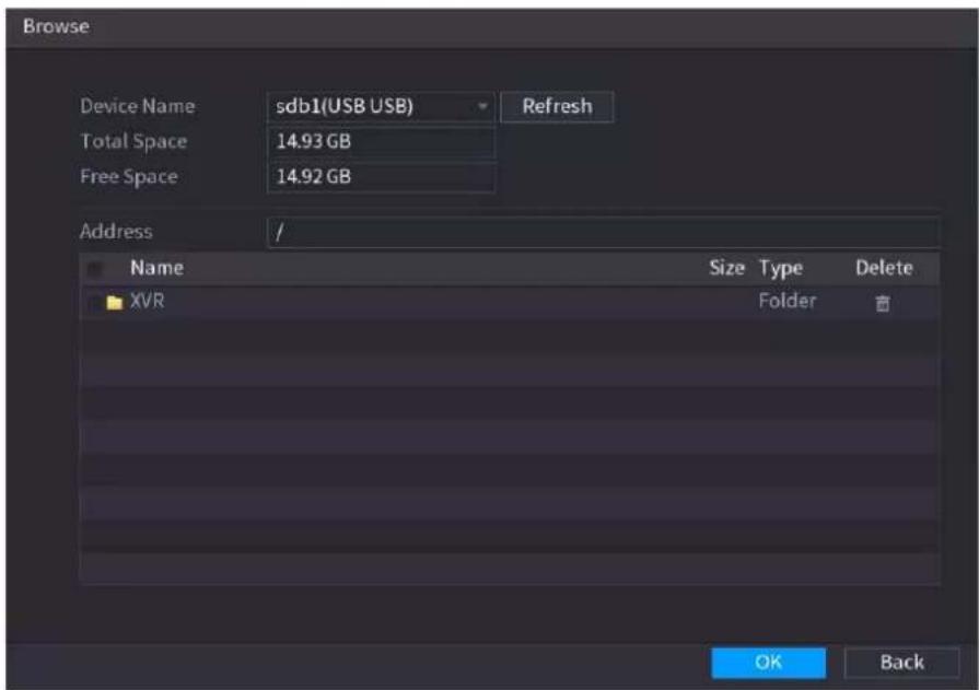
Step 5 Select a face picture and enter the registration information.
Figure 5-156 Register ID
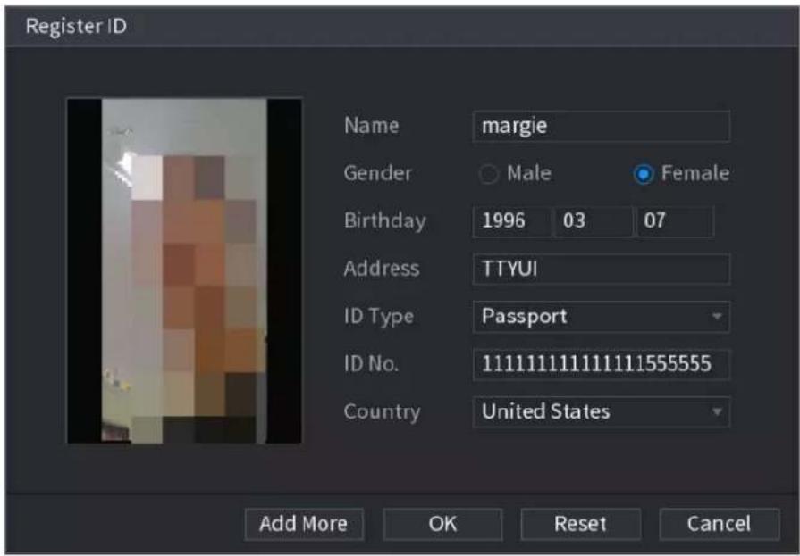
Step 6 Click OK.
The system prompts the registration is successful.
Step 7 On the Details page, click Search.
The system prompts modeling is successful.

If the system prompts the message indicating modeling is in process, wait a while and then click Search again. If modeling is failed, the registered face picture cannot be used for face recognition.
Figure 5-157 Details
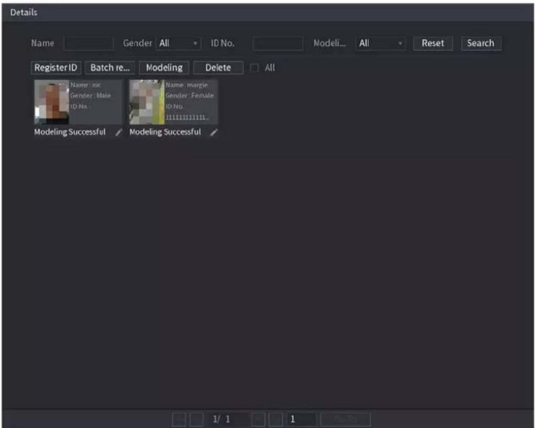
Adding Face Pictures in Batch
Step 1 Give a name to the face picture.
Table 5-36 Register ID
| Naming format Description | |
| Name Enter the name. | |
| Gender | Enter 1 or 2. 1 represents male, and 2 represents female. |
| Birthday | Enter numbers in the format of yyyy-mm-dd. |
| Country | Enter the abbreviation of country. For example, CN for China. |
| ID Type | 1 represents ID card; 2 represents passport; 3 represents officer password. |
| ID No. Enter the ID number. | |
| Address Enter the address. | |
Step 2 On the Details page, click Batch register.
Figure 5-158 Batch register
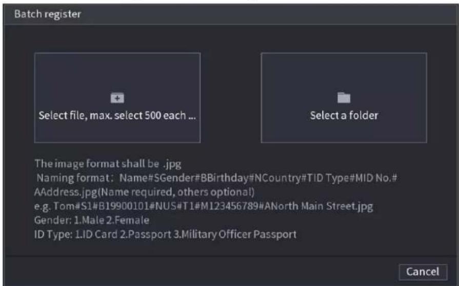
Step 3 Click Select file, max select 500 each time or Select a folder to import face pictures.
Step 4 Click OK to complete batch registration.
Adding the Detected Faces
Step 1 Right-click on the live view screen, and then select Live Mode > AI Mode.
Figure 5-159 AI mode live view
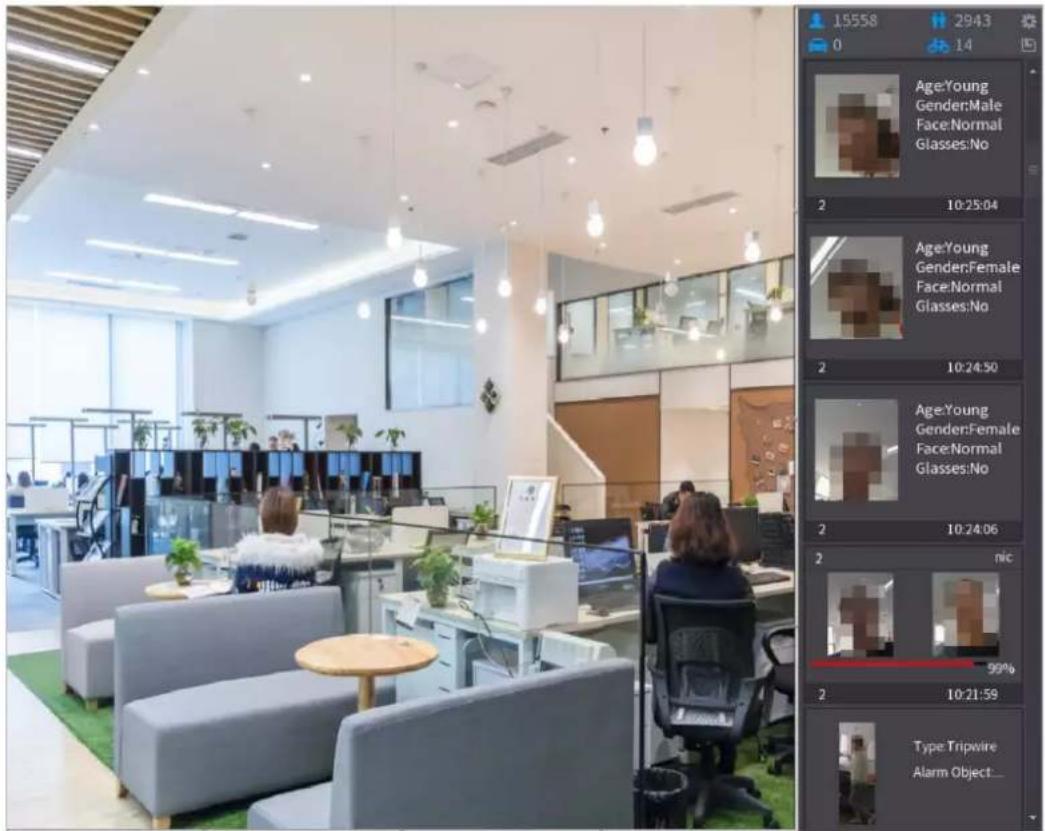
Step 2 Double-click the detected face snapshot that you want to add.
Figure 5-160 Playback
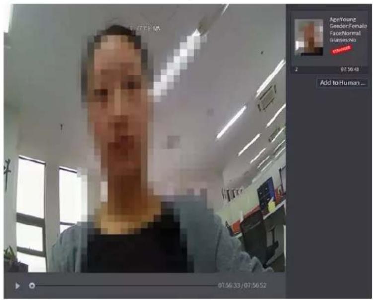
Step 3 Click Add to Human Face Database.
Figure 5-161 Register ID
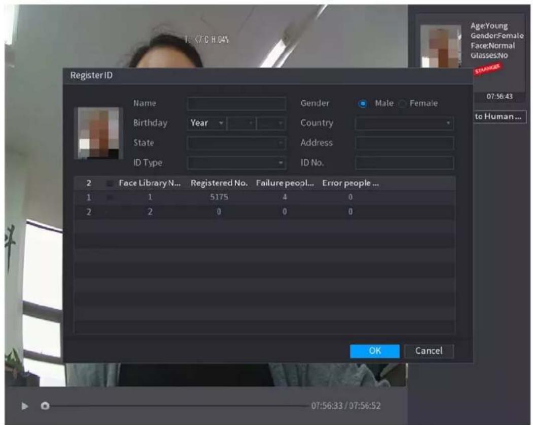
Step 4 Select the face database and enter the ID information.
Step 5 Click OK to complete registration.
5.11.2.2.2 Face Recognition Configuration
You can compare the detected faces with the faces in the database to judge if the detected face belongs to the database. The comparison result will be displayed on the AI mode live view screen and smart search page, and link the alarms.
Step 1 Select Main Menu > AI > Parameters > Face Recognition.
Figure 5-162 Face recognition
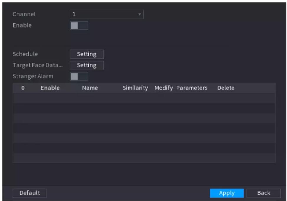
Step 2 In the Channel list, select a channel that you want to configure face recognition function, and then enable it.
Step 3 Set the Schedule. For details, see "5.10.4.1 Configuring Motion Detection Settings".
Step 4 Set the Target Face Database.
1) Click Setting.
Figure 5-163 Face database
2) Select one or multiple face databases.
3) Click OK.
The selected face database is listed.
Figure 5-164 Selected face database
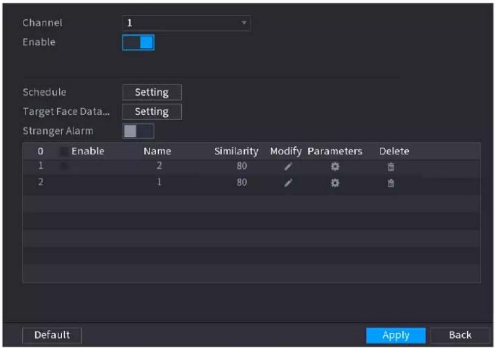
Step 5 Configure the added face database.
- Click to modify the similarity. The lower the number is, the easier the alarm linkage will trigger.
- Click to delete the face database.
- Click ⚙ to set the alarm linkage.
After setting is completed, click OK.
Step 6 (Optional) Enable the Stranger Mode.
1) Enable the Stranger mode (☐). When the detected faces do not belong to the face database, the system remarks the face as "Stranger".
2) Click Setting to set the alarm linkage.
3) After setting is completed, click OK.
Step 7 Click Apply to complete the settings.
After the face recognition function is enabled, right-click on the live view screen, and then select Live Mode > AI Mode.
- If the detected face belongs to the enabled face database, the similarity result is displayed.
- If the detected face does not belong to the enabled face database, the face will be remarked as "Stranger".
Figure 5-165 Similarity result
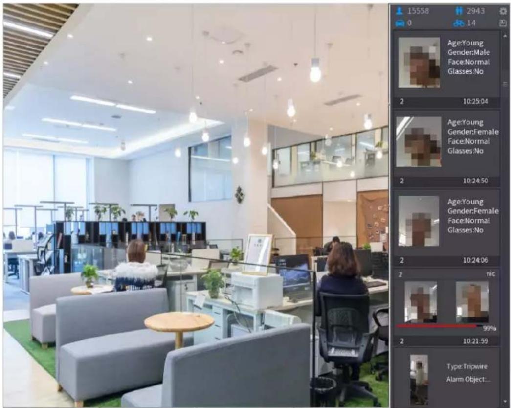
5.11.2.2.3 Smart Search for Face Recognition
You can compare the detected faces with the face database and play back.
- Search by attributes: Search the face database by the face attributes.
- Search by picture: Search the face database by uploading face pictures.
Searching by Attributes
Step 1 Select Main Menu > AI > AI Search > Face Recognition > Search by Attributes.
Figure 5-166 Search by attributes
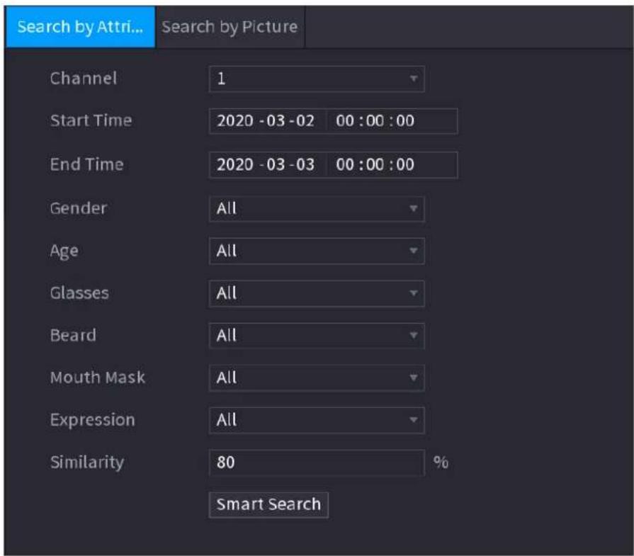
Step 2 Select the channel and set the parameters such as start time, end time, gender, age, glasses, beard, mask, and similarity according to your requirement.
Step 3 Click Smart Search.
Figure 5-167 Smart search
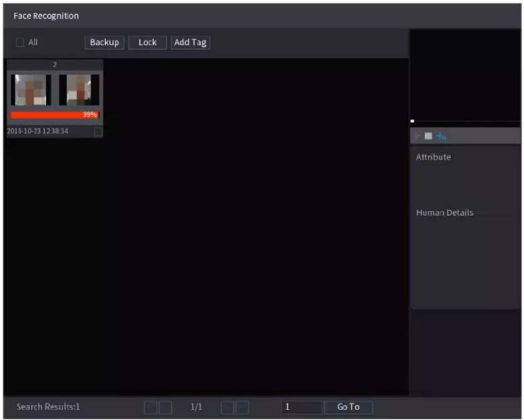
Step 4 Click the picture that you want to play back.
Figure 5-168 Registered information
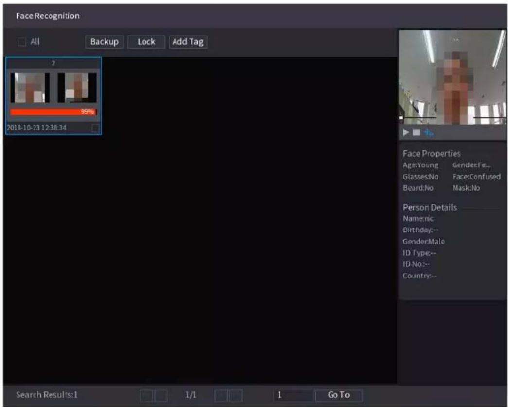
Step 5
Click

to play back the recorded video.

Double-click on the playing page to switch between full screen playing and thumbnail playing.
You can also do the following operations to the recorded files.
- To export the database file (.csv) to the external storage device, select files, click Export, and then select the save path.
- To back up the recorded files to the external storage device, select files, click Backup, select the save path and file type, and then click Start.
Figure 5-169 Backup
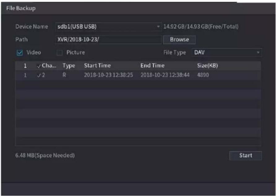
- To lock the files to make it unable to be overwritten, select the files, and then click Lock.
• To add a mark to the file, select the files and then click Add Tag.
Search by Picture
Step 1 Select Main Menu > AI > AI Search > Face Recognition > Search by Picture.
Figure 5-170 Search by picture
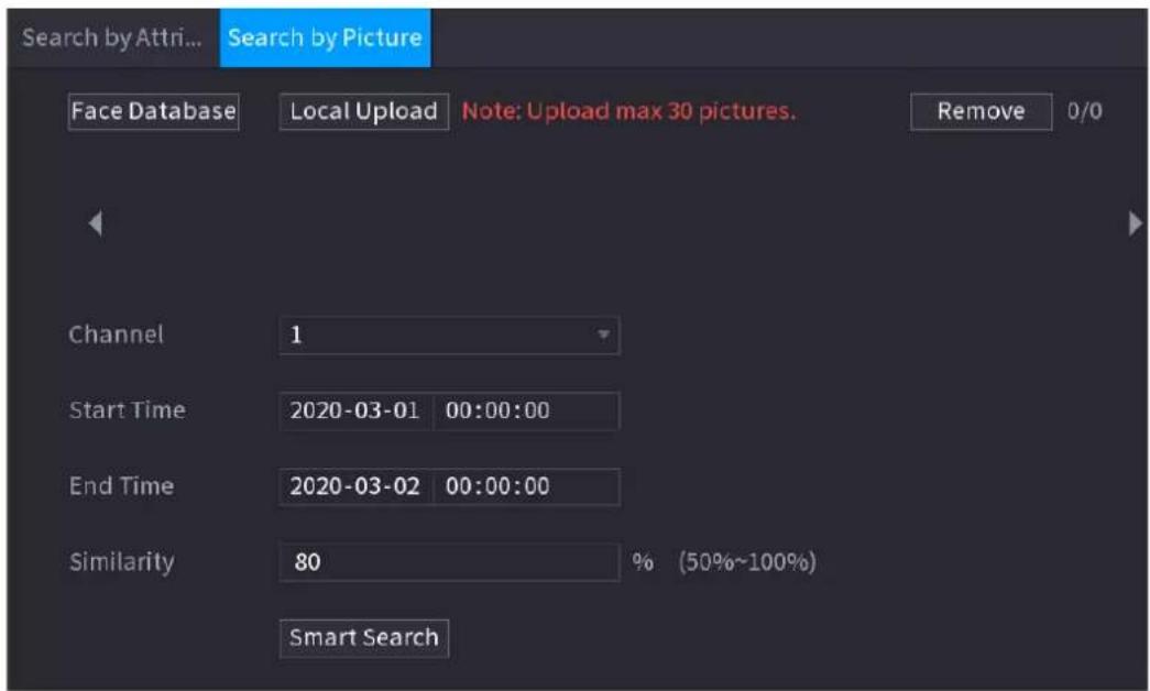
Step 2 Upload face pictures from Face Database or Local Upload.

Maximum 30 pictures can be uploaded at one time, and the system support searching 8 pictures at one time.
- Face Database
1) Click Face Database.
Figure 5-171 Face database
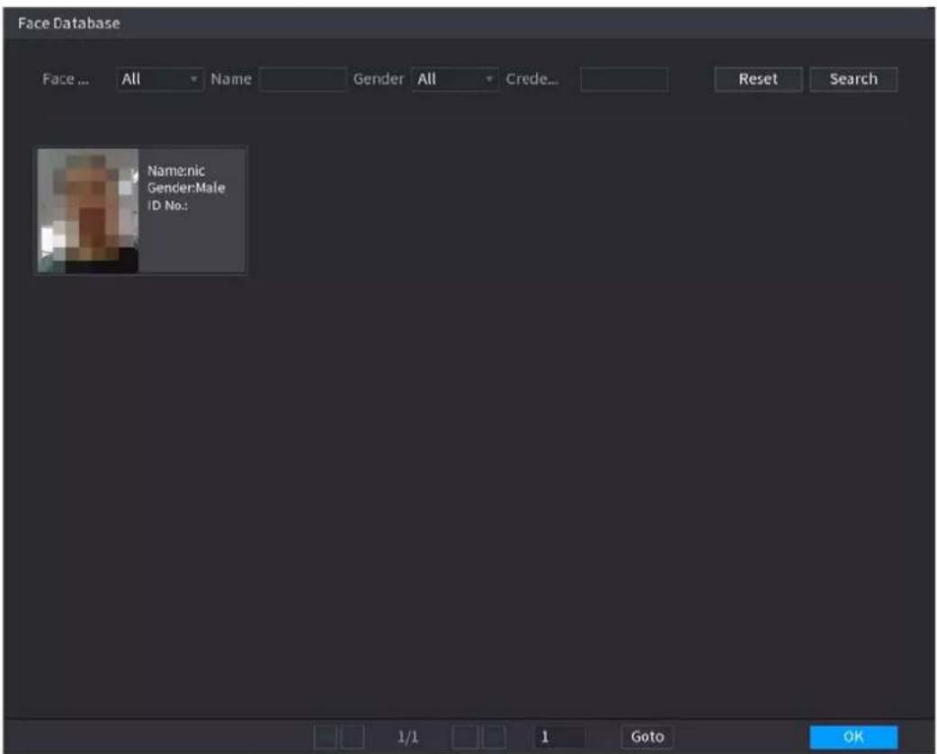
2) Set the searching parameters by selecting the face database and gender, and entering name and ID No. according to your actual requirement.
3) Click Search to display the results that satisfy the requirement.

Click Reset to clear the searching parameters.
4) Select the picture and then click OK.
Figure 5-172 Uploaded picture
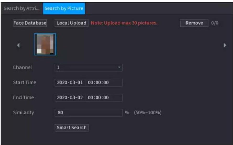
- Local Upload
Plug the USB storage device (with face pictures) to the Device, and then click Local Upload. Then select the picture from the USB storage device, and then click OK. The selected face pictures are uploaded.
Step 3 After the face pictures are uploaded, continue to configure other parameters (channel, start time, end time, and similarity).
Step 4 Click Smart Search.
The searching results are displayed.
Figure 5-173 Search results
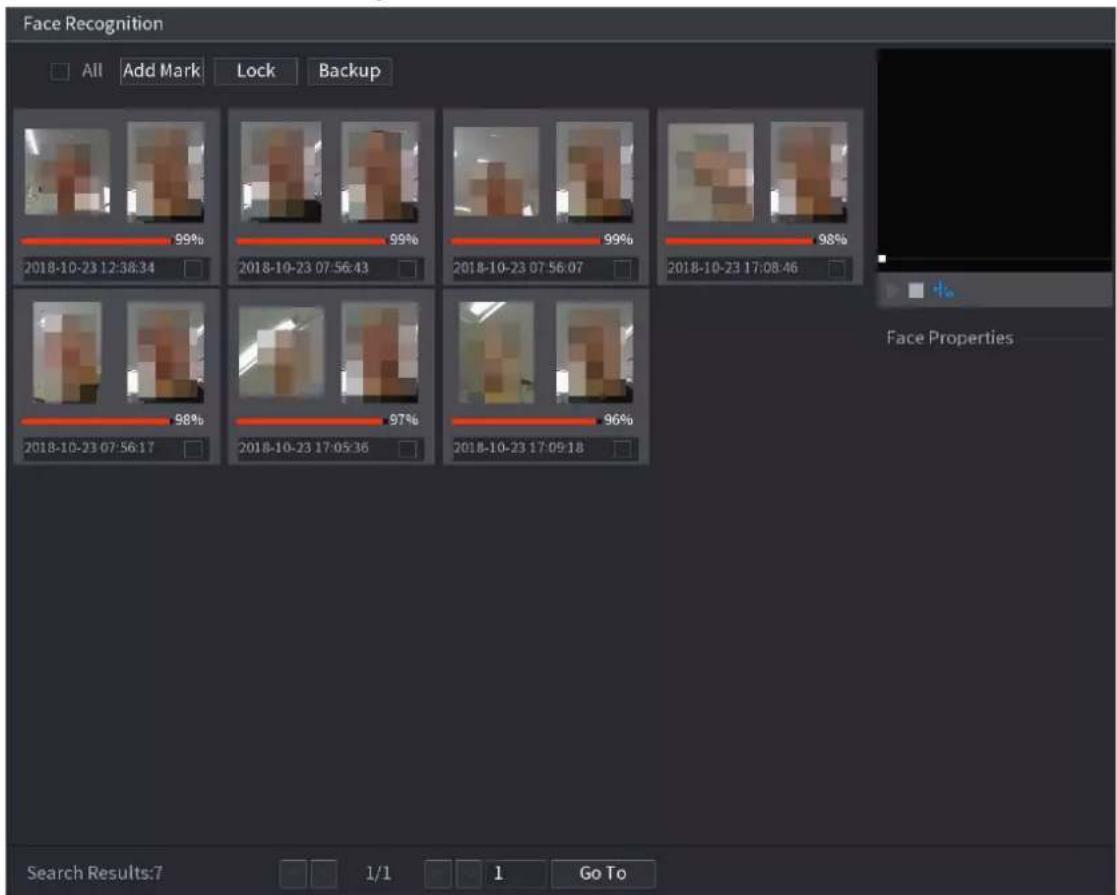
Step 5 Select the face picture that you want to play back.
Figure 5-174 Playback
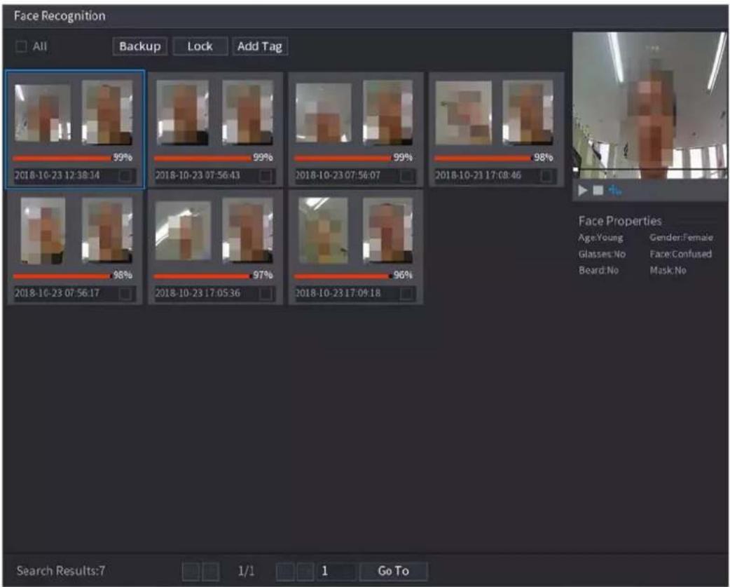
Step 6
Click

to play back the recorded video.

Double-click on the playing page to switch between full screen playing and thumbnail playing.
You can also do the following operations to the recorded files.
• To add a mark to the file, select the files and then click Add Tag.
- To lock the files to make it unable to be overwritten, select the files, and then click Lock.
- To back up the recorded files to the external storage device, select files, click Backup, select the save path and file type, and then click Start.
Figure 5-175 Backup
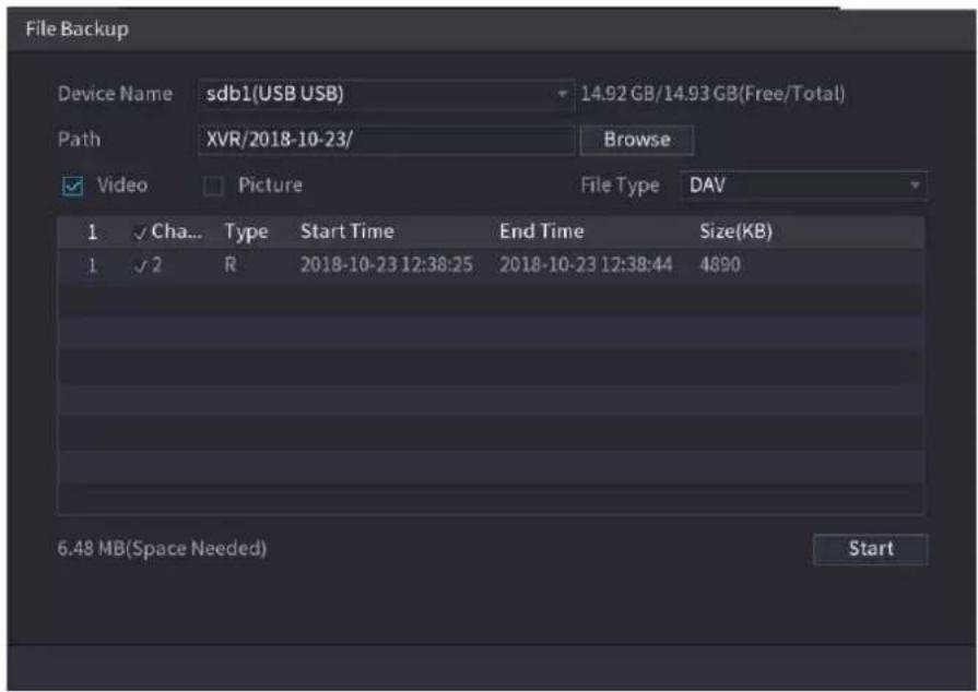
5.11.2.3 IVS Function
The IVS function processes and analyzes the images to extract the key information to match with the preset rules. When the detected behaviors match with the rules, the system activates alarms.

If you select AI by device, then among face detection and recognition, IVS function, and video structuring, you can use one of them at the same time for the same channel.
5.11.2.3.1 Configuring IVS Parameters
The alarms are generated according to the configured parameters.
Step 1 Select Main Menu > AI > Parameters > IVS.
Figure 5-176 IVS
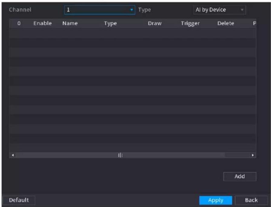
Step 2 In the Channel list, select the channel number that you want to configure the IVS function.
Step 3 At Type, you can select from AI by Camera and AI by Device.
- AI by Camera: This option requires certain AI cameras. The camera will do all the AI analysis, and then give the results to the DVR.
- AI by Device: The camera only transmits normal video stream to the DVR, and then the DVR will do all the AI analysis.
Step 4 Click Add.
Figure 5-177 Added rule
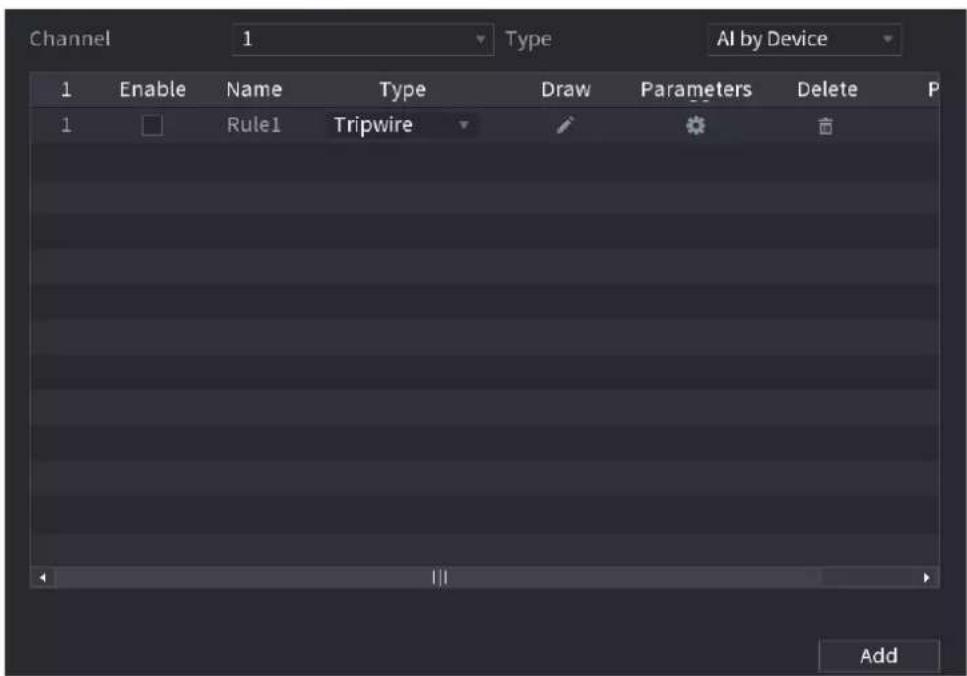
Step 5 Configure the parameters for the rule that you selected.
Step 6 Select the checkbox of the rule to enable it.
Step 7 Click Apply to complete the settings.
Configuring Tripwire Rules
When the target object crosses the tripwire in the defined direction, the system activates alarms.
● The tripwire can be configured as a straight line or broken line.
● Supports detecting one-way or two-way tripwire crossing.
• Supports multiple tripwires in the same scenario to meet the complexity.
• Supports size filtering for target.
Step 1 On the rule line that you added, in the Type list, select Tripwire.
Figure 5-178 Tripwire
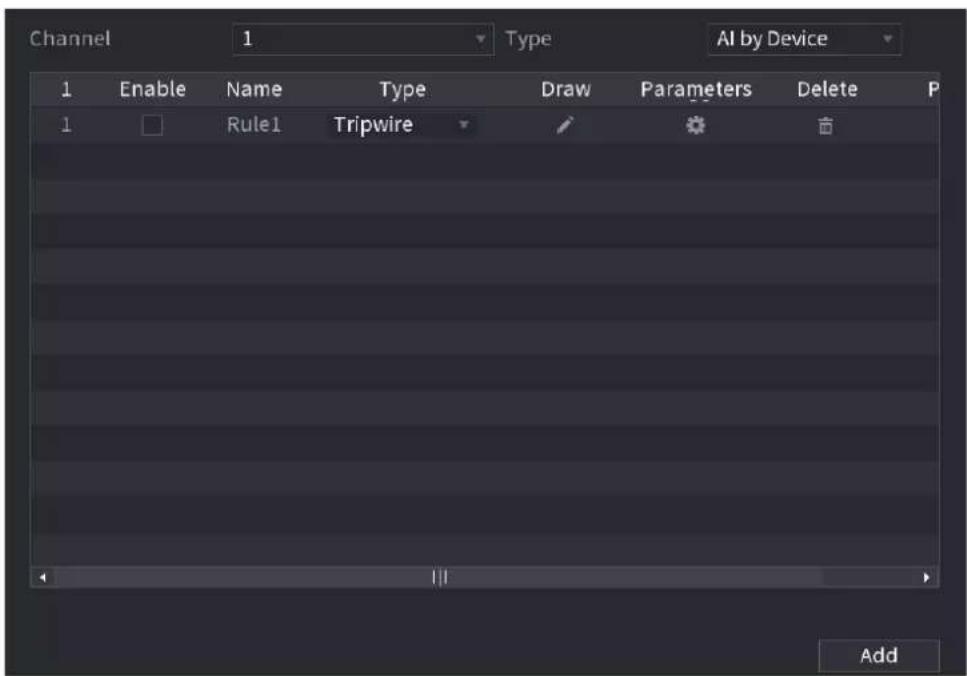
Step 2 Draw a tripwire.
1) In the Channel list, select the channel that you want to configure the rules for.
2) Click.

Figure 5-179 Tripwire rule
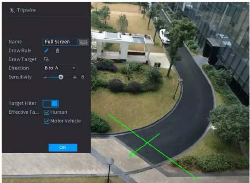
3) Click to draw the minimum size or maximum size to filter the target.
The system triggers an alarm only when the size of detected target is between the maximum size and the minimum size.
4) Configure the parameters.
Figure 5-180 Tripwire parameters
| Parameter Description | |
| Name | Enter the customized rule name. |
| Direction | Set the direction of the tripwire. You can choose A to B (left to right), B to A (right to left), and Both. |
| Sensitivity | Configure the detection sensitivity.The higher the value, the easier to trigger an alarm but meanwhile the higher false alarm rate. |
| Target Filter | Click □ and then select effective target. With Human and Motor Vehicle selected by default, the system automatically identifies the person and motor vehicle appeared within the monitoring range. |
| Effective Target |
5) Drag to draw a tripwire. The tripwire can be a straight line, broken line or polygon.
6) Click OK to save the settings.
Step 3
Click

to set the actions to be triggered.
Figure 5-181 Trigger
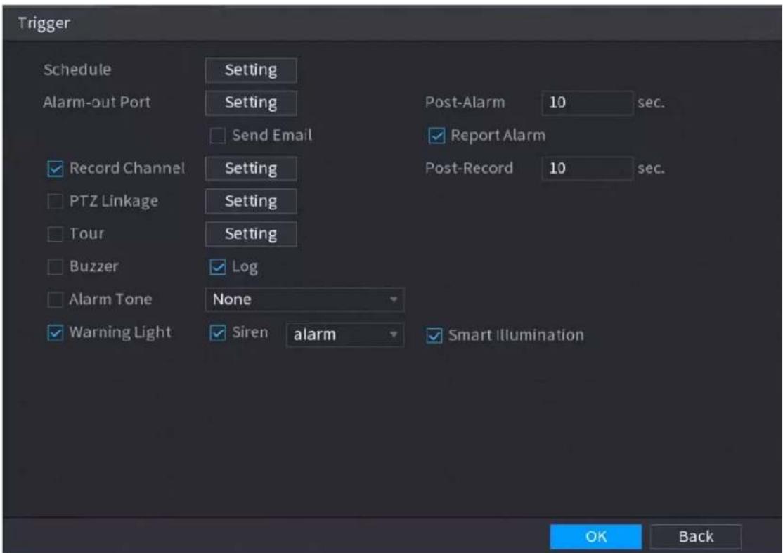
Step 4 Configure the triggering parameters.
Figure 5-182 Triggering parameters
| Parameter Description | |
| Schedule | Define a period during which the detection is active.For details, see "Setting Motion Detection Period" section in "5.10.4.1 Configuring Motion Detection Settings". |
| Alarm-out Port | Click Setting to configure the parameters.General Alarm: Enable general alarm and select the alarm output port.Ext. Alarm: Connect the alarm box to the Device and then enable it.Wireless Siren: Connect the wireless gateway to the Device and then enable it. For details, see "5.12 IoT Function".When an alarm event occurs, the system links the peripheral alarm devices connected to the selected output port. |
| Post-Alarm | Set a length of time for the Device to delay turning off alarm after the external alarm is cancelled. The value ranges from 0 seconds to 300 seconds. If you enter 0, there will be no delay. |
| Show Message | Select the Show Message checkbox to enable a pop-up alarm message in your local host PC. |
| Report Alarm | Select theReport Alarmcheckbox to enable the system to upload the alarm signal to the network (including alarm center) when an alarm event occurs.This function is available on select models.The corresponding parameters in the alarm center should be configured. For details, see "5.15.1.12 Configuring Alarm Center Settings". |
| Send Email | Select theSend Emailcheckbox to enable the system to send an email notification when an alarm event occurs.To use this function, make sure the email function is enabled inMain Menu >NETWORK >EMAIL. |
| Record Channel | Select the channel(s) that you want to record. The selected channel(s) starts recording after an alarm event occurs.The recording for intelligence event and auto recording function must be enabled. For details, see "5.1.4.9 Configuring Recorded Video Storage Schedule" and "5.9.1 Enabling Record Control". |
| PTZ Linkage | ClickSettingto display the PTZ page.Enable PTZ linkage actions, such as selecting the preset that you want to be called when an alarm event occurs.To use this function, the PTZ operations must be configured. For details, see "5.4 Controlling PTZ Cameras". |
| Post-Record | Set a length of time for the Device to delay turning off recording after the alarm is cancelled. The value ranges from 10 seconds to 300 seconds. |
| Tour | Select theTourcheckbox to enable a tour of the selected channels.To use this function, the tour setting must be configured.After the tour is ended, the live view screen returns to the view layout before tour started. |
| Picture Storage | Select thePicture Storagecheckbox to take a snapshot of the selected channel.To use this function, make sure the snapshot function is enabled forIntel in Main Menu >STORAGE >Schedule >Picture Storage. |
| Video Matrix | Select the checkbox to enable the function. When an alarm event occurs, the video output port outputs the settings configured inMain Menu >DISPLAY >Tour >Sub Screen.This function is available on select models.The extra screen must be enabled to support this function. |
| Buzzer | Select the checkbox to activate a buzzer noise at the Device. |
| Log | Select the checkbox to enable the Device to record a local alarm log. |
| Alarm Tone | Select to enable audio broadcast in response to a face detection event. |
| Warning Light | Select the checkbox to enable the warning light alarm of the camera. |
| Siren | Select the checkbox to enable the sound alarm of the camera. |
| Smart Illumination | Select the checkbox to enable the smart illumination of the camera. |
Step 5 Click OK to save the settings.
Step 6 Select the Enable checkbox, and then click Apply.
The tripwire detecting function is active. When the target object crosses the tripwire in the defined direction, the system activates alarms.
Configuring Intrusion Rules
When the target enters and leaves the defined detection area, or the target appears in the defined area, the system activates alarms.
- You can define the shape and quantity of intrusion areas.
● Supports detecting the behaviors that enter and leave the intrusion areas. - Supports detecting the behaviors that are moving in the intrusion areas. The quantity of areas and lasting time can be configured.
• Supports size filtering for target.
Step 1 On the rule line that you added, in the Type list, select Intrusion.
Figure 5-183 Intrusion
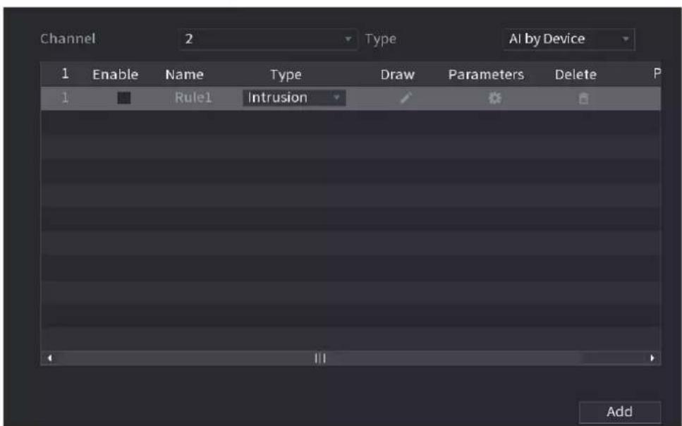
Step 2 Draw an area.
1) In the Channel list, select the channel that you want to configure the rules for.
Figure 5-184 Intrusion rule
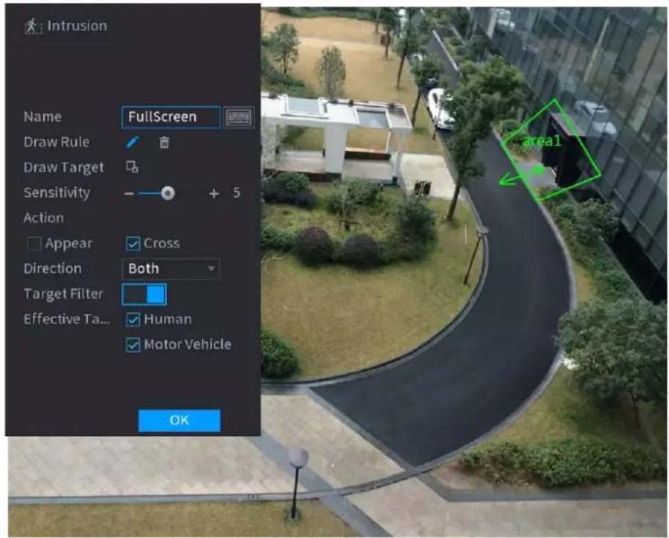
3) Click ☐ to draw the minimum size or maximum size to filter the target.
The system triggers an alarm only when the size of detected target is between the maximum size and the minimum size.
4) Configure the parameters.
Figure 5-185 Intrusion parameters
| Parameter Description | |
| Name | Enter the customized rule name. |
| Sensitivity | Configure the detection sensitivity.The higher the value, the easier to trigger an alarm but meanwhile the higher false alarm rate. |
| Action | Set the intrusion action, including appear and crossing area. |
| Direction | Set the intrusion direction. You can select Enter, Exit, and Both. |
| Target Filter | Click □ and then select effective target. With Human and Motor Vehicle selected by default, the system automatically identifies the person and motor vehicle appeared within the monitoring range. |
| Effective Target |
5) Drag to draw an area.
6) Click OK to save the settings.
Step 3 Click to set the actions to be triggered.
Step 4 Select the Enable checkbox, and then click Apply.
The intrusion detecting function is active. When the target enters and leaves the area, or the target appears in the defined area, the system activates alarms.
5.11.2.3.2 Smart Search for IVS Function
You can search for the intelligent events and play back.
Step 1 Select Main Menu > AI > SMART SEARCH > IVS.
Figure 5-186 IVS
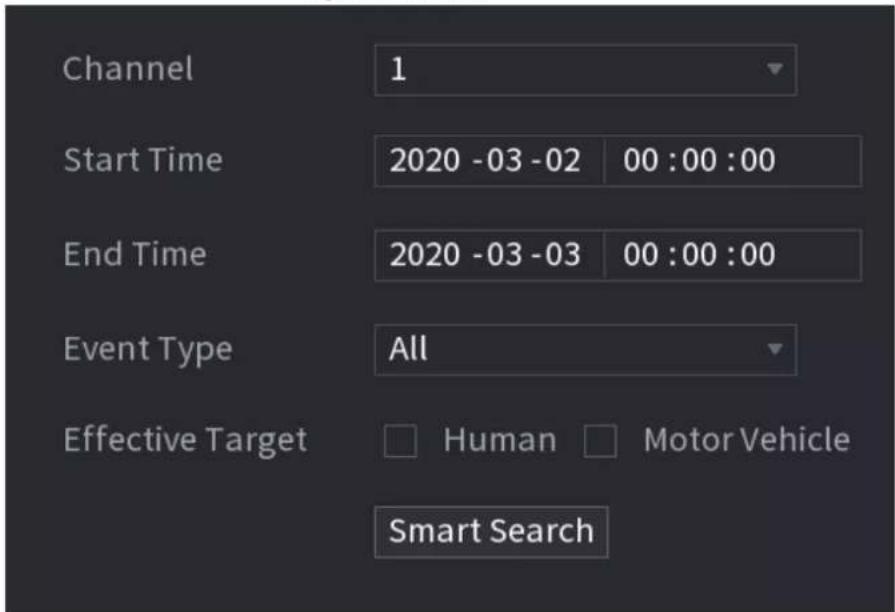
Step 2 In the Channel list, select the channel that you want to search for the events, and then set other parameters such as start time, end time, event type, and alarm object.
Step 3 Click Smart Search.
The results that satisfy the searching conditions are displayed.
Figure 5-187 Search results
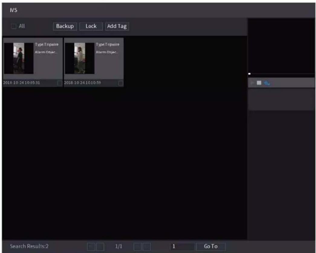
Step 4 Click the picture that you want to play back.
Figure 5-188 Playback
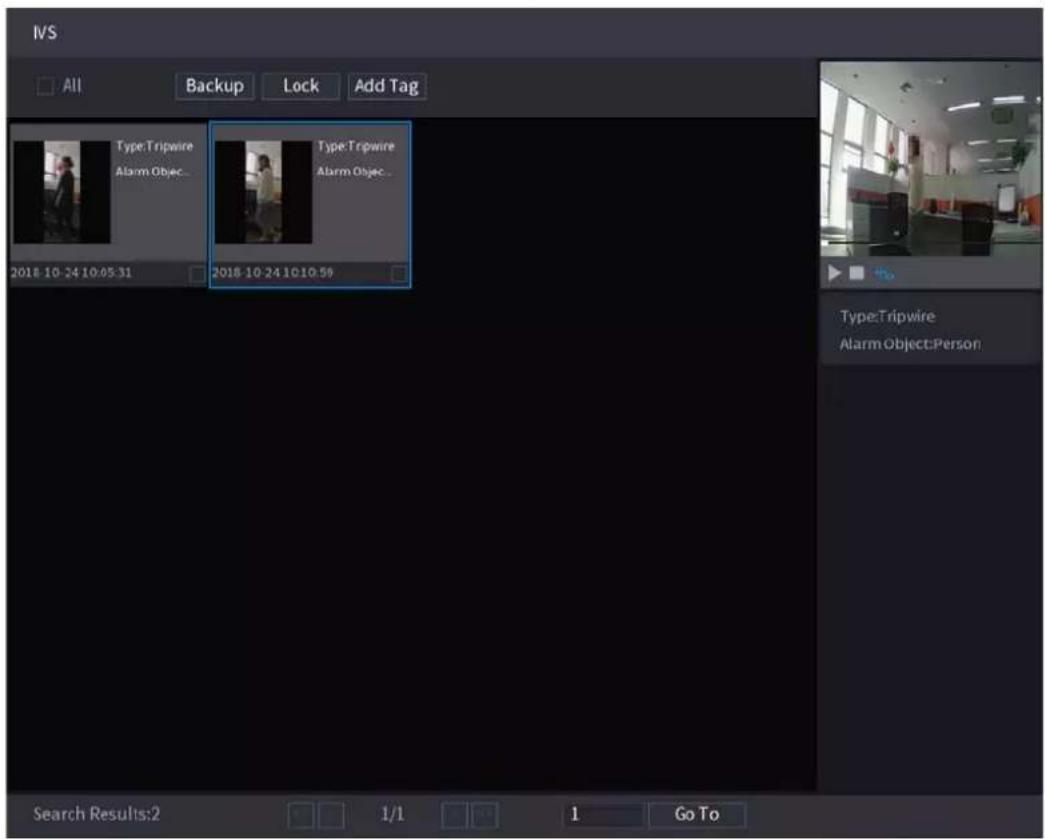
Step 5
Click

to play back the recorded video.

Double-click on the playing page to switch between full screen playing and thumbnail playing.
You can also do the following operations to the recorded files.
- To back up the recorded files to the external storage device, select files, click Backup, select the save path and file type, and then click Start.
Figure 5-189 Backup
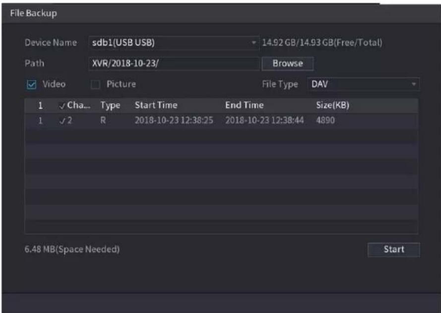
- To lock the files to make it unable to be overwritten, select the files, and then click Lock.
• To add a mark to the file, select the files and then click Add Tag.
5.11.2.4 Video Structuring
The device can detect and extract key features from the human bodies and non-motor vehicles in the video, and then build a structured database. You can search any target you need with these features.
5.11.2.4.1 Configuring Video Structuring
Step 1 Select Main Menu > AI > Parameters > Video Structuring.
Figure 5-190 Video structuring
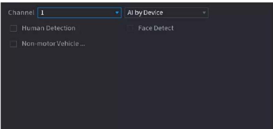
Step 2 In the Channel list, select a channel that you want to configure video structuring function, and then enable it.
Step 3 At Type, you can select from AI by Camera and AI by Device.
- AI by Camera: This option requires certain AI cameras. The camera will do all the AI analysis, and then give the results to the DVR.
- AI by Device: The camera only transmits normal video stream to the DVR, and then the DVR will do all the AI analysis.
Step 4 You can select from Human Detection, Face Detect, and Non-motor Vehicle.
- Human Detection: Select this option, and then the device will analyze all the human body features in the video, including Top, Top Color, Bottom, Bottom Color, Hat, Bag, Gender, Age, and Umbrella. You can search the target you need with these features. See "Human Body Detection" in "5.11.1.4.2 Smart Search for Video Structuring".
- Face Detect: You need to select Human Detection first, and then you can select this option. If you select this option, and there is any human face appears in the video, then there will be an extra face image and some extra face features in the human body detection results, including Glasses, Expression, Mask, and Beard. You can search the target you need with these features. See "Human Body Detection" in "5.11.1.4.2 Smart Search for Video Structuring".
- Non-motor Vehicle: Select this option, and then the device will analyze all the non-motor vehicle features in the video, including Type, Vehicle Color, People Number, and Helmet. You can search the target you need with these features. See "Non-motor Vehicle Detection" in "5.11.1.4.2 Smart Search for Video Structuring".
Step 5 Click Apply.
5.11.2.4.2 Smart Search for Video Structuring
You can search the target you need with human body features or non-motor vehicle features Human Body Detection
Step 1 Select Main Menu > AI > SMART SEARCH > Human Body Detection.
Figure 5-191 Human body detection
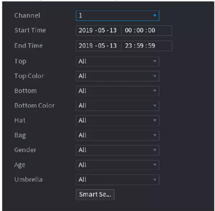
Step 2 Select the channel and the time, and then select one or multiple features from Top, Top Color, Bottom, Bottom Color, Hat, Bag, Gender, Age, or Umbrella.
Step 3 Click Smart Search.
- If you only selected Human Body Detection and did not select Face Detection in "5.11.1.4.1 Configuring Video Structuring", there will be only human body features displayed in the results.
Figure 5-192 Human body detection
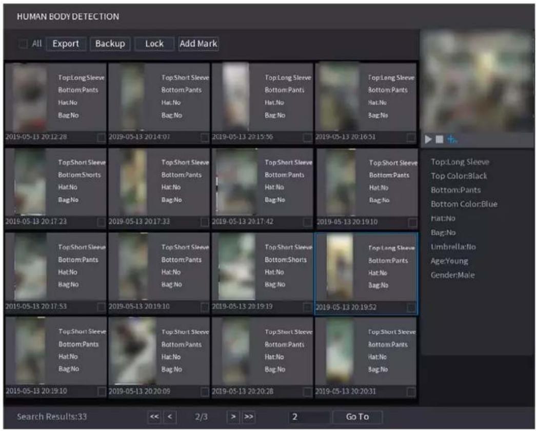
- If you selected Human Body Detection and Face Detection in "5.11.1.4.1 Configuring Video Structuring", and there is any human face appears in the video, there will be extra face features displayed in the results.
Figure 5-193 Extra face features
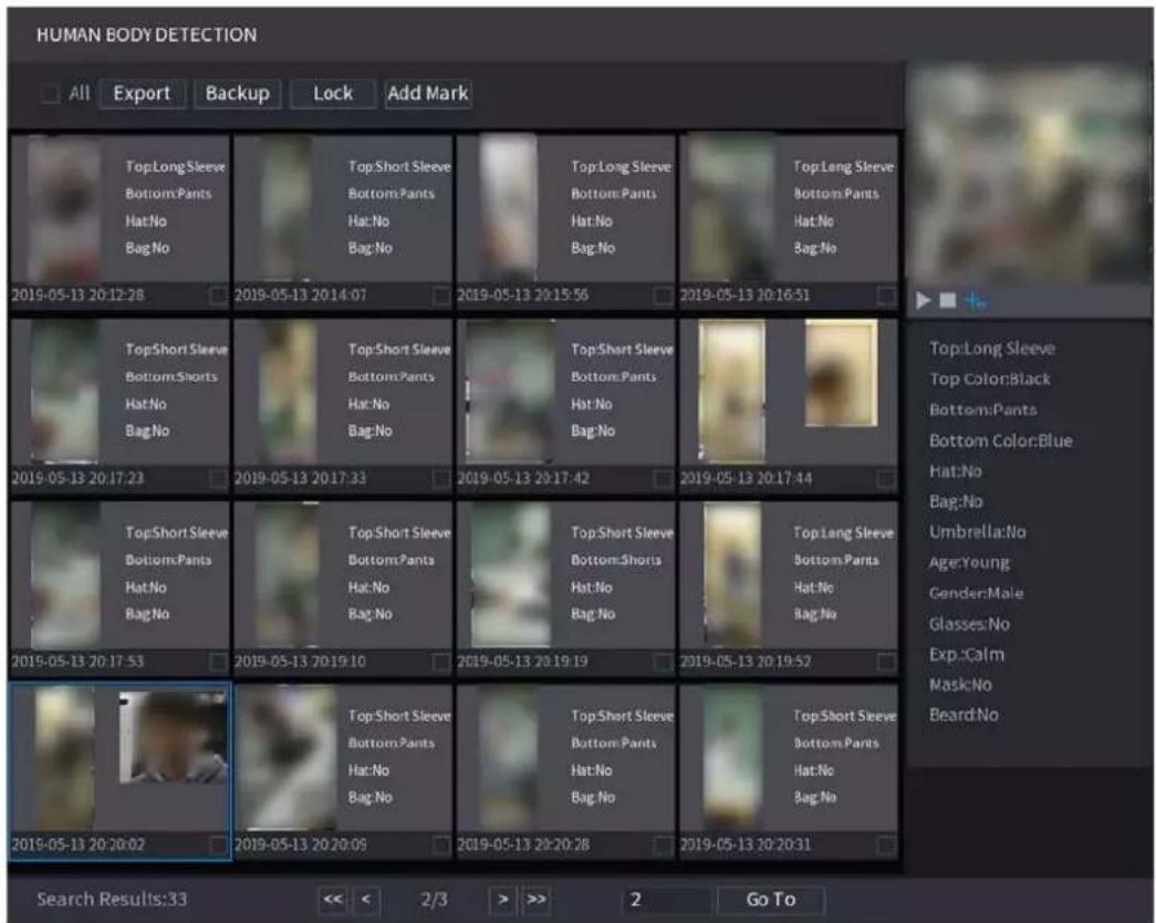
Step 4 Select one or multiple results, and then you can
- Click Export to export them to the USB device
- Click Backup to make backup in the DVR
- Click Lock so that they don't get overwritten or deleted
- Click Add Tag to name them as needed.
Non-motor Vehicle Detection
Step 1 Select Main Menu > AI > AI Search > Non-motor Vehicle Detection.
Figure 5-194 Non-motor vehicle detection
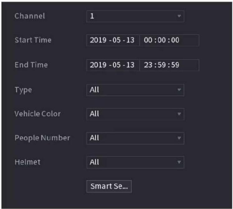
Step 2 Select the channel and the time, and then select one or multiple features from Type, Vehicle Color, People Number, or Helmet.
Step 3 Click Smart Search.
Figure 5-195 Search results
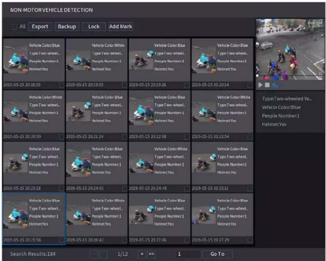
Step 4 Select one or multiple results, and then you can
- Click Export to export them to the USB device
- Click Backup to make backup in the DVR
- Click Lock so that they don't get overwritten or deleted
- Click Add Tag to name them as needed.
5.11.3 For Lite AI Series
AI module provides SMD (Smart Motion Detection) and IVS functions. These functions take effect after they are configured and enabled. It adopts deep learning and can realize precision alarms. You can only enable one of them to the same channel at the same time.
- SMD: The device can detect and classify humans and vehicles in the image.
- IVS: The IVS function processes and analyzes the human and vehicle images to extract the key information to match with the preset rules. When the detected behaviors match with the rules, the system activates alarms. The IVS function can avoid wrong alarms by filtering the factors such as rains, light, and animals.
- Face detection: The Device can analyze the faces captured by the camera and link the configured alarms. This function is available for XVR5X-I and XVR 7X-I series only.
- Face recognition: The Device can compare the captured faces with the face database and then link the configured alarms. This function is available for XVR 7X-I series only.

SMD, face detection, face recognition and IVS cannot be enabled simultaneously on select models. For details, see "5.1.4.2 Configuring General Settings".
5.11.3.1 SMD
The device can detect and classify humans and vehicles in the image.
5.11.3.1.1 Configuring SMD Parameters
Step 1 Select Main Menu > AI > Parameters > SMD.
Figure 5-196 SMD
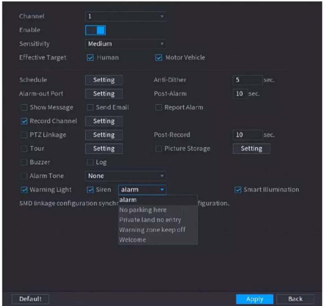
Step 2 In the Channel list, select a channel, and then enable it.
Step 3 Configure the parameters.
Figure 5-197 SMD parameters
| Parameter Description | |
| Channel | In the Channel list, select a channel to set the motion detection. |
| Enable Enable or disable | the motion detection function. |
| Sensitivity | Set the sensitivity for smart motion detection. |
| Effective Target | Select human or motor vehicle or both. |
| Schedule | Define a period during which the motion detection is active. |
| Anti-Dither | Configure the time period from end of event detection to the stop of alarm. |
| Alarm-out Port | Click Setting to configure the parameters.General Alarm: Enable alarm activation through the alarm devices connected to the selected output port.External Alarm: Enable alarm activation through the connected alarm box.Wireless Siren: Enable alarm activation through devices connected by USB gateway or camera gateway. |
| Post-Alarm | Set a length of time for the Device to delay turning off alarm after the external alarm is cancelled. The value ranges from 0 seconds to 300 seconds, and the default value is 10 seconds. If you enter 0, there will be no delay. |
| Show Message | Select the Show Message checkbox to enable a pop-up message in your local host PC. |
| Report Alarm | Select the Report Alarm checkbox to enable the system to upload the alarm signal to the network (including alarm center) when an alarm event occurs. |
| Send Email | Select the Send Email checkbox to enable the system to send an email notification when an alarm event occurs.To use this function, make sure the email function is enabled in Main Menu > NETWORK > Email. |
| Record Channel | Select the channel(s) that you want to record. The selected channel(s) starts recording after an alarm event occurs.The recording for motion detection and auto recording function must be enabled. For details, see "5.1.4.9 Configuring Recorded Video Storage Schedule" and "5.9.1 Enabling Record Control". |
| PTZ Linkage | Click Setting to display the PTZ page.Enable PTZ linkage actions, such as selecting the preset that you want to be called when an alarm event occurs.Motion Detect can only activate PTZ preset. |
| Post Record | Set a length of time for the Device to delay turning off recording after the alarm is cancelled. The value ranges from 10 seconds to 300 seconds, and the default value is 10 seconds. |
| Tour | Select the Tour checkbox to enable a tour of the selected channels. |
| Picture Storage | Select the Snapshot checkbox to take a snapshot of the selected channel.To use this function, select Main Menu > CAMERA > Encode > Snapshot, in the Type list, select Event. |
| Sub Screen | Select the checkbox to enable the function. When an alarm event occurs, the extra screen outputs the settings configured in Main Menu > DISPLAY > Tour > Sub Screen.This function is available on select models.To use this function, extra screen shall be enabled. |
| Video Matrix | Select the checkbox to enable the function. When an alarm event occurs, the video output port outputs the settings configured inMain Menu > DISPLAY > Tour.This function is available on select models. |
| Buzzer | Select the checkbox to activate a buzzer noise at the Device. |
| Log | Select the checkbox to enable the Device to record a local alarm log. |
| Alarm Tone | Select to enable audio broadcast/alarm tones in response to a motion detection event. |
| Warning Light | Select the checkbox to enable warning light alarm of the camera. |
| Siren | Select the checkbox to enable sound alarm of the camera. |
| Smart Illumination | Select the checkbox to enable the smart illumination of the camera. |
Step 4 Click Apply to complete the settings.
5.11.3.1.2 Searching for SMD Reports
You can search the detection history by channel, object type, and time.
Step 1 Select Main Menu > AI > AI Search > SMD.
Figure 5-198 SMD
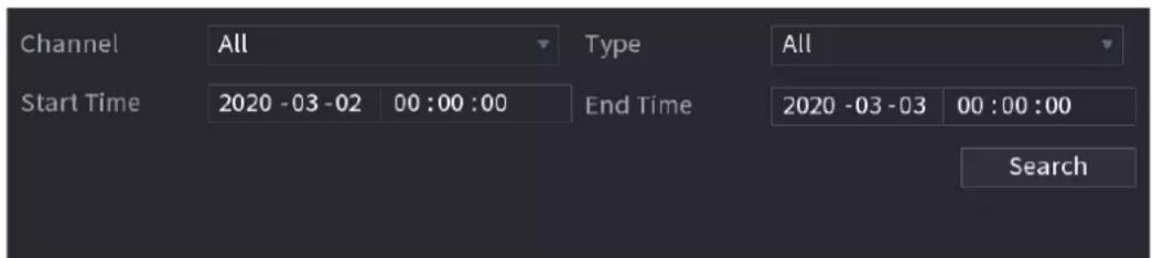
Step 2 Select the channel, enter the start time and end time, and select the object type you need.
Step 3 Click Search.
The results are displayed.
5.11.3.2 Configuring IVS Function
The IVS function processes and analyzes the images to extract the key information to match with the preset rules. When the detected behaviors match with the rules, the system activates alarms.
5.11.3.2.1 Configuring IVS Parameters
The alarms are generated according to the configured parameters.
Step 1 Select Main Menu > AI > Parameters > IVS.
Figure 5-199 IVS
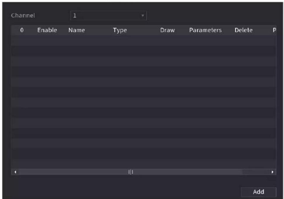
You can enable the AI Mode, and then the detection accuracy would be improved, but the video stream quantity that the DVR can process will reduce.
Step 2 In the Channel list, select the channel number that you want to configure the IVS function.
Step 3 Click Add.
Figure 5-200 Added rule
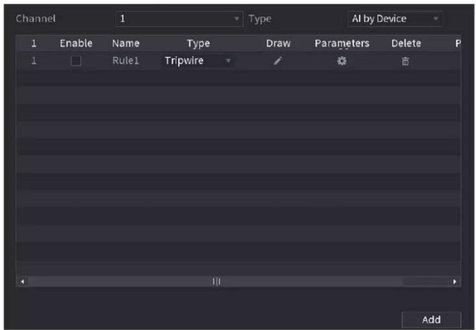
Step 4 Configure the parameters for the rule that you selected.
Step 5 Select the checkbox of the rule to enable it.
Step 6 Click Apply to complete the settings.
Configuring Tripwire Rules
When the target object crosses the tripwire in the defined direction, the system activates alarms.
● The tripwire can be configured as a straight line or broken line.
● Supports detecting one-way or two-way tripwire crossing.
• Supports multiple tripwires in the same scenario to meet the complexity.
• Supports size filtering for target.
Step 1 On the rule line that you added, in the Type list, select Tripwire.
Figure 5-201 Tripwire
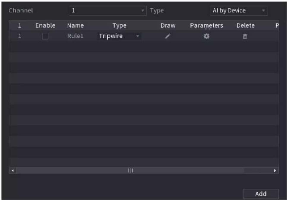
Step 2 Draw a tripwire.
1) In the Channel list, select the channel that you want to configure the rules for.
2) Click.
Figure 5-202 Tripwire rule
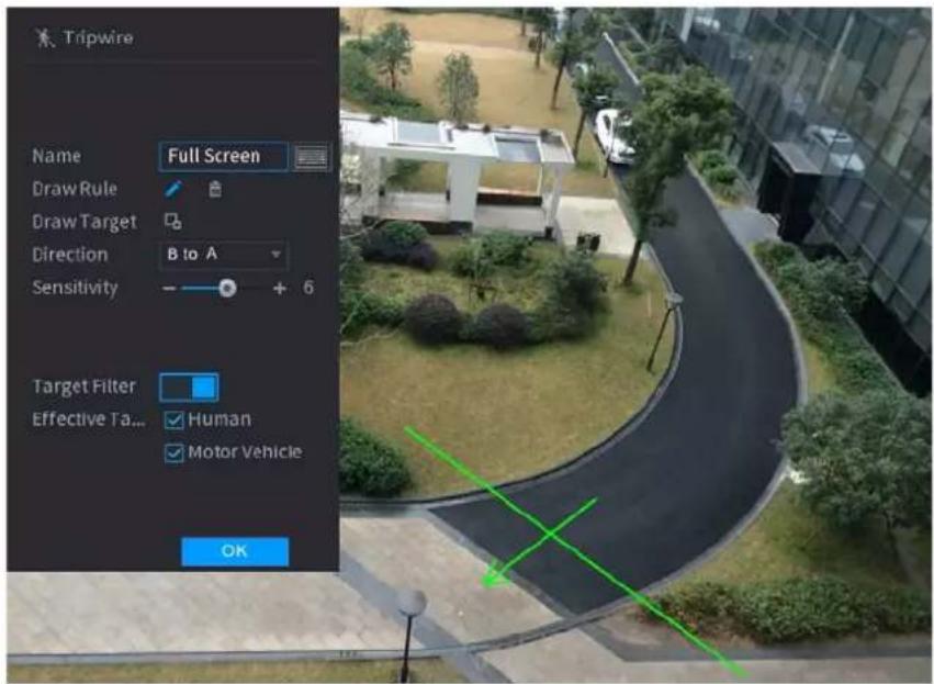
3) Click to draw the minimum size or maximum size to filter the target.
The system triggers an alarm only when the size of detected target is between the maximum size and the minimum size.
4) Configure the parameters.
Figure 5-203 Tripwire parameters
| Parameter Description | |
| Name | Enter the customized rule name. |
| Direction | Set the direction of the tripwire. You can choose A to B (left to right), B to A (right to left), and Both. |
| Sensitivity | Configure the detection sensitivity.The higher the value, the easier to trigger an alarm but meanwhile the higher false alarm rate. |
| Target Filter | Click □ and then select effective target. With Human and Motor Vehicle selected by default, the system automatically identifies the person and motor vehicle appeared within the monitoring range. |
| Effective Target |
5) Drag to draw a tripwire. The tripwire can be a straight line, broken line or polygon.
6) Click OK to save the settings.
Step 3
Click

to set the actions to be triggered.
Figure 5-204 Trigger
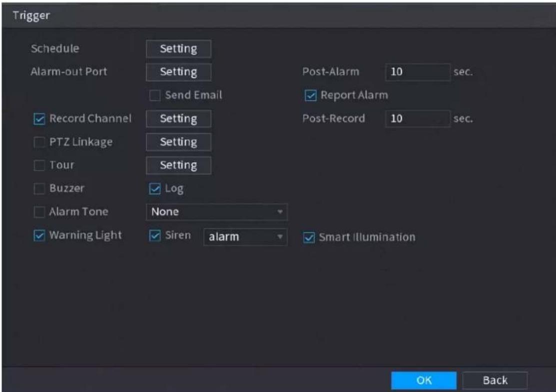
Step 4 Configure the triggering parameters.
Table 5-37 Triggering parameters
| Parameter Description | |
| Schedule | Define a period during which the detection is active.For details, see "Setting Motion Detection Period" section in "5.10.4.1 Configuring Motion Detection Settings". |
| Alarm-out Port | Click Setting to configure the parameters.General Alarm: Enable general alarm and select the alarm output port.Ext. Alarm: Connect the alarm box to the Device and then enable it.Wireless Siren: Connect the wireless gateway to the Device and then enable it. For details, see "5.12 IoT Function".When an alarm event occurs, the system links the peripheral alarm devices connected to the selected output port. |
| Post-Alarm | Set a length of time for the Device to delay turning off alarm after the external alarm is cancelled. The value ranges from 0 seconds to 300 seconds. If you enter 0, there will be no delay. |
| Show Message | Select the Show Message checkbox to enable a pop-up alarm message in your local host PC. |
| Report Alarm | Select theReport Alarmcheckbox to enable the system to upload the alarm signal to the network (including alarm center) when an alarm event occurs.This function is available on select models.The corresponding parameters in the alarm center should be configured. For details, see "5.15.1.12 Configuring Alarm Center Settings". |
| Send Email | Select theSend Emailcheckbox to enable the system to send an email notification when an alarm event occurs.To use this function, make sure the email function is enabled inMain Menu > NETWORK > Email. |
| Record Channel | Select the channel(s) that you want to record. The selected channel(s) starts recording after an alarm event occurs.The recording for intelligence event and auto recording function must be enabled. For details, see "5.1.4.9 Configuring Recorded Video Storage Schedule" and "5.9.1 Enabling Record Control". |
| PTZ Linkage | ClickSettingto display the PTZ page.Enable PTZ linkage actions, such as selecting the preset that you want to be called when an alarm event occurs.To use this function, the PTZ operations must be configured. For details, see "5.4 Controlling PTZ Cameras". |
| Post-Record | Set a length of time for the Device to delay turning off recording after the alarm is cancelled. The value ranges from 10 seconds to 300 seconds. |
| Tour | Select theTourcheckbox to enable a tour of the selected channels.To use this function, the tour setting must be configured.After the tour is ended, the live view screen returns to the view layout before tour started. |
| Picture Storage | Select theSnapshotcheckbox to take a snapshot of the selected channel.To use this function, make sure the snapshot function is enabled forIntel in Main Menu > STORAGE > Schedule > Snapshot. |
| Video Matrix | Select the checkbox to enable the function. When an alarm event occurs, the video output port outputs the settings configured inMain Menu > DISPLAY > Tour > Sub Screen.This function is available on select models.The extra screen must be enabled to support this function. |
| Buzzer | Select the checkbox to activate a buzzer noise at the Device. |
| Log | Select the checkbox to enable the Device to record a local alarm log. |
| Alarm Tone | Select to enable audio broadcast in response to a face detection event. |
| Warning Light | Select the checkbox to enable the warning light alarm of the camera. |
| Siren | Select the checkbox to enable the sound alarm of the camera. |
| Smart Illumination | Select the checkbox to enable the smart illumination of the camera. |
Step 5 Click OK to save the settings.
Step 6 Select the Enable checkbox, and then click Apply.
The tripwire detecting function is active. When the target object crosses the tripwire in the defined direction, the system activates alarms.
Configuring Intrusion Rules
When the target enters and leaves the defined detection area, or the target appears in the defined area, the system activates alarms.
- You can define the shape and quantity of intrusion areas.
● Supports detecting the behaviors that enter and leave the intrusion areas. - Supports detecting the behaviors that are moving in the intrusion areas. The quantity of areas and lasting time can be configured.
• Supports size filtering for target.
Step 1 On the rule line that you added, in the Type list, select Intrusion.
Figure 5-205 Intrusion
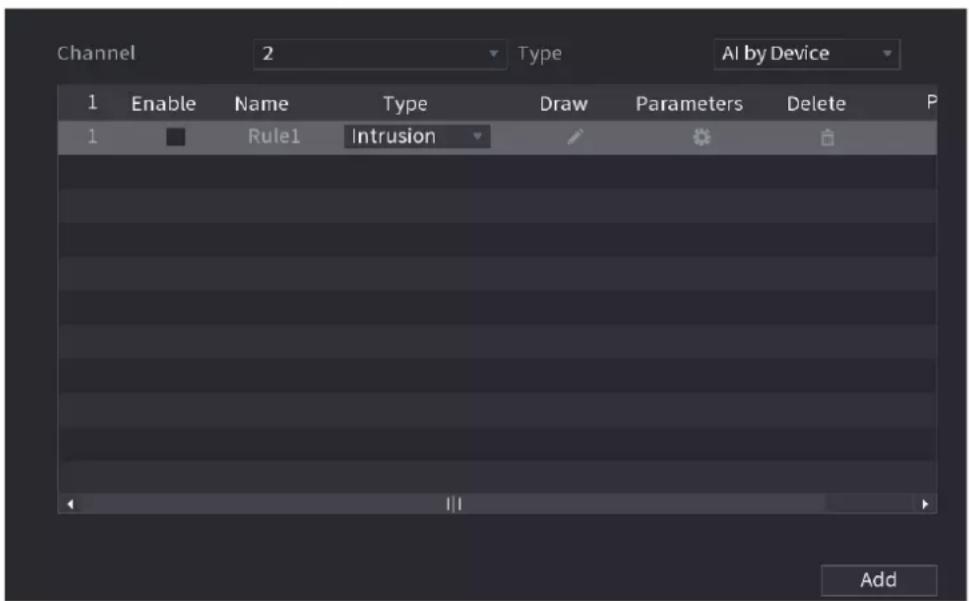
Step 2 Draw an area.
1) In the Channel list, select the channel that you want to configure the rules for.
2) Click

Figure 5-206 Intrusion rule
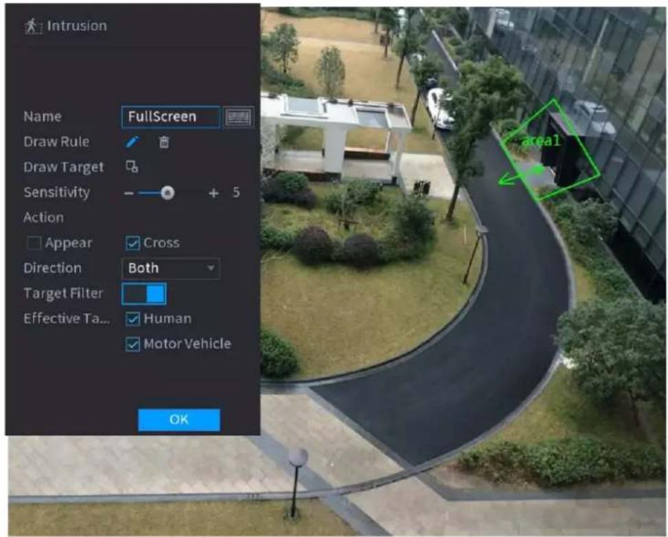
3) Click ☐ to draw the minimum size or maximum size to filter the target.
The system triggers an alarm only when the size of detected target is between the maximum size and the minimum size.
4) Configure the parameters.
Figure 5-207 Intrusion parameters
| Parameter Description | |
| Name | Enter the customized rule name. |
| Sensitivity | Configure the detection sensitivity.The higher the value, the easier to trigger an alarm but meanwhile the higher false alarm rate. |
| Action | Set the intrusion action, including appear and crossing area. |
| Direction | Set the intrusion direction. You can select Enter, Exit, and Both. |
| Target Filter | Click □ and then select effective target. With Human and Motor Vehicle selected by default, the system automatically identifies the person and motor vehicle appeared within the monitoring range. |
| Effective Target |
5) Drag to draw an area.
6) Click OK to save the settings.
Step 3 Click to set the actions to be triggered.
Step 4 Select the Enable checkbox, and then click Apply.
The intrusion detecting function is active. When the target enters and leaves the area, or the target appears in the defined area, the system activates alarms.
5.11.3.2.2 Smart Search for IVS Function
You can search for the intelligent events and play back.
Step 1 Select Main Menu > AI > AI Search > IVS.
Figure 5-208 IVS
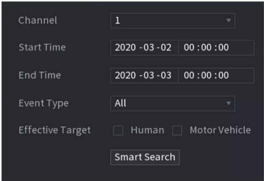
Step 2 In the Channel list, select the channel that you want to search for the events, and then set other parameters such as start time, end time, event type, and alarm object.
Step 3 Click Smart Search.
The results that satisfy the searching conditions are displayed.
Figure 5-209 Search results
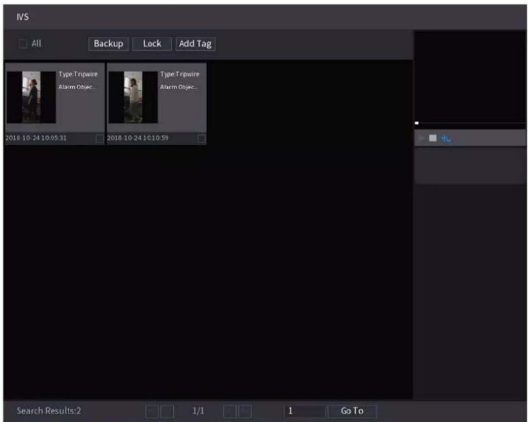
Step 4 Click the picture that you want to play back.
Figure 5-210 Playback
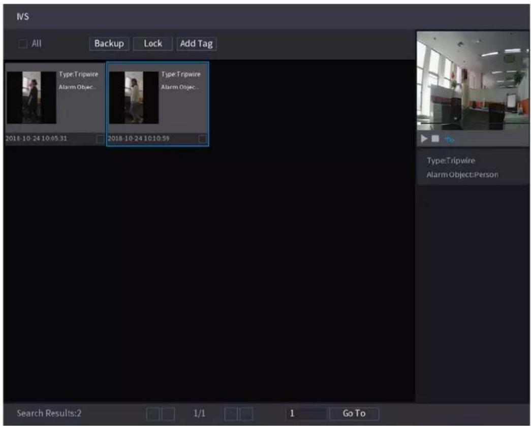
Step 5
Click

to play back the recorded video.

Double-click on the playing page to switch between full screen playing and thumbnail playing.
You can also do the following operations to the recorded files.
- To back up the recorded files to the external storage device, select files, click Backup, select the save path and file type, and then click Start.
Figure 5-211 Backup
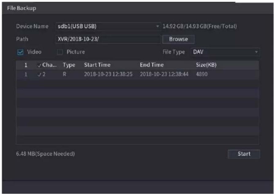
- To lock the files to make it unable to be overwritten, select the files, and then click Lock.
• To add a mark to the file, select the files and then click Add Tag.
5.11.3.3 Face Detection (For XVR5X-I and XVR7X-I series only)
Some series of devices can analyze the pictures captured by the camera to detect whether the faces are on the pictures. You can search and filter the recorded videos the faces and play back.

If you select AI by device, then among face detection and recognition, IVS function, you can use one of them at the same time for the same channel.
5.11.3.3.1 Configuring Face Detection Parameters
The alarms are generated according to the configured parameters.
Step 1 Select Main Menu > AI > Parameters > Face Detection.
Figure 5-212 Face detection
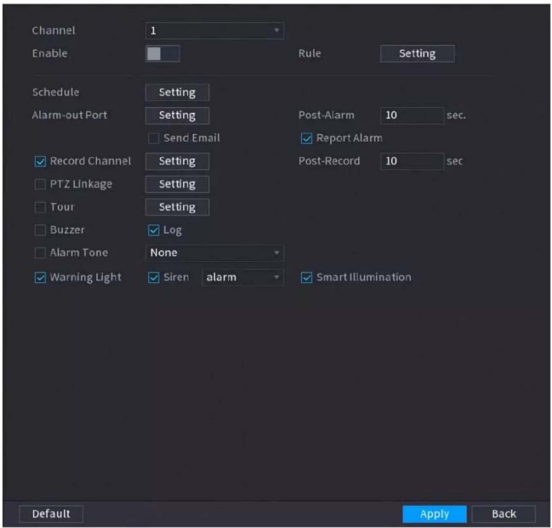
Step 2 In the Channel list, select a channel that you want to configure face detection function, and then enable it.
Step 3 Configure the parameters.
Table 5-38 Face detection parameters
| Parameter Description | |
| Rule | Click View Setting to draw areas to filter the target.You can configure two filtering targets (maximum size and minimum size). When the target is smaller than the minimum size or larger than the maximum size, no alarms will be activated. The maximum size should be larger than the minimum size. |
| Schedule | Define a period during which the detection is active.For details, see "Setting Motion Detection Period" section in "5.10.4.1 Configuring Motion Detection Settings". |
| Alarm-out Port | Click Setting to configure the parameters.General Alarm: Enable general alarm and select the alarm output port.Ext. Alarm: Connect the alarm box to the Device and then enable it.Wireless Siren: Connect the wireless gateway to the Device and then enable it. For details, see "5.12 IoT Function".When an alarm event occurs, the system links the peripheral alarm devices connected to the selected output port. |
| Post-Alarm | Set a length of time for the Device to delay turning off alarm after the external alarm is cancelled. The value ranges from 0 seconds to 300 seconds. If you enter 0, there will be no delay. |
| Show Message | Select the Show Message checkbox to enable a pop-up alarm message in your local host PC. |
| Report Alarm | Select the Report Alarm checkbox to enable the system to upload the alarm signal to the network (including alarm center) when an alarm event occurs.This function is available on select models.The corresponding parameters in the alarm center should be configured. For details, see "5.15.1.12 Configuring Alarm Center Settings". |
| Send Email | Select the Send Email checkbox to enable the system to send an email notification when an alarm event occurs.To use this function, make sure the email function is enabled in Main Menu > NETWORK > Email. |
| Record Channel | Select the channel(s) that you want to record. The selected channel(s) starts recording after an alarm event occurs.The recording for intelligence event and auto recording function must be enabled. For details, see "5.1.4.9 Configuring Recorded Video Storage Schedule" and "5.9.1 Enabling Record Control". |
| PTZ Linkage | Click Setting to display the PTZ page.Enable PTZ linkage actions, such as selecting the preset that you want to be called when an alarm event occurs.To use this function, the PTZ operations must be configured. For details, see "5.4 Controlling PTZ Cameras". |
| Post Record | Set a length of time for the Device to delay turning off recording after the alarm is cancelled. The value ranges from 10 seconds to 300 seconds. |
| Tour | Select the Tour checkbox to enable a tour of the selected channels.To use this function, the tour setting must be configured".After the tour is ended, the live view screen returns to the view layout before tour started. |
| Picture Storage | Select the Picture Storage checkbox to take a snapshot of the selected channel.To use this function, make sure the snapshot function is enabled for Intel in Main Menu > STORAGE > Schedule > Snapshot. |
| Video Matrix | Select the checkbox to enable the function. When an alarm event occurs, the video output port outputs the settings configured in Main Menu > DISPLAY > TOUR > Extra Screen.This function is available on select models.The extra screen must be enabled to support this function. |
| Buzzer | Select the checkbox to activate a buzzer noise at the Device. |
| Log | Select the checkbox to enable the Device to record a local alarm log. |
| Alarm Tone | Select to enable audio broadcast in response to a face detection event. |
| Warning Light | Select the checkbox to enable the warning light alarm of the camera. |
| Siren | Select the checkbox to enable the sound alarm of the camera. |
| Smart Illumination | Select the checkbox to enable the smart illumination of the camera. |
Step 4 Click Apply to complete the settings.
5.11.3.3.2 Searching for and Playing Detected Faces
You can search the detected faces and play back.
Step 1 Select Main Menu > AI > AI Search > Face Detection.
Figure 5-213 Face detection
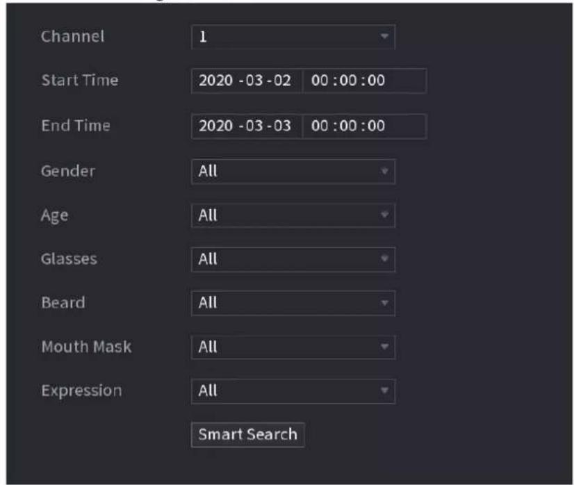
Step 2 Select the channel, enter the start time and end time, and set for the gender, age, glasses, beard, and mask.
Step 3 Click Smart Search.
The results are displayed.
Figure 5-214 Search results
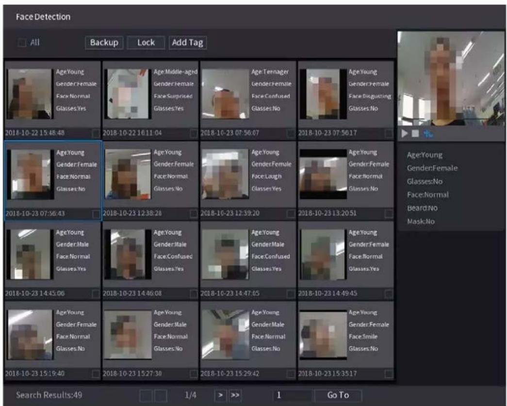
Step 4 Select the face that you want to play back.
Figure 5-215 Registered information
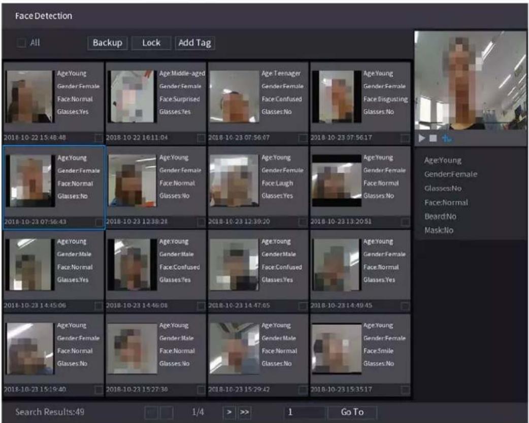
Step 5 And then click ▶ to start playing back the recorded detected face snapshots.

Double-click on the playing page to switch between full screen playing and thumbnail playing.
You can also do the following operations to the recorded files.
- To export the database file (.csv) to the external storage device, select files, click Export, and then select the save path.
- To back up the recorded files to the external storage device, select files, click Backup, select the save path and file type, and then click Start.
Figure 5-216 Backup
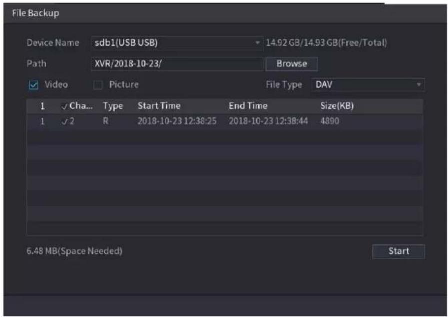
- To lock the files to make it unable to be overwritten, select the files, and then click Lock.
• To add a mark to the file, select the files and then click Add Tag.
5.11.3.4 Face Recognition (For XVR7X-I series only)
Face recognition applies to AI preview mode and smart search.
- AI preview mode: Supports comparing the detected faces with the face database, and display the comparison results.
• Smart search: Supports faces searching by faces attributes or portraits.

- If you select AI by device, then among face detection and recognition, IVS function, you can use one of them at the same time for the same channel.
- Before enabling face recognition function for a channel, the face detection must be enabled first for this channel.
5.11.3.4.1 Face Database Management
You should create a face database for comparing the detected faces and the faces in the database. The Device supports creating maximum 20 databases and registering 100,000 faces.
Creating a Face Database
Step 1 Select Main Menu > AI > Database > Face Database Config.
Figure 5-217 Face database configuration
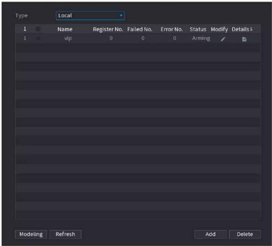
Step 2 At Type, you can select Local or Remote.
- Local: Viewing the existing face databases or adding new one on the DVR.
- Remote: If you have face recognition camera, you can select this to view the existing face databases or adding new one on the camera.
Step 3 Click Add.
Figure 5-218 Add face database
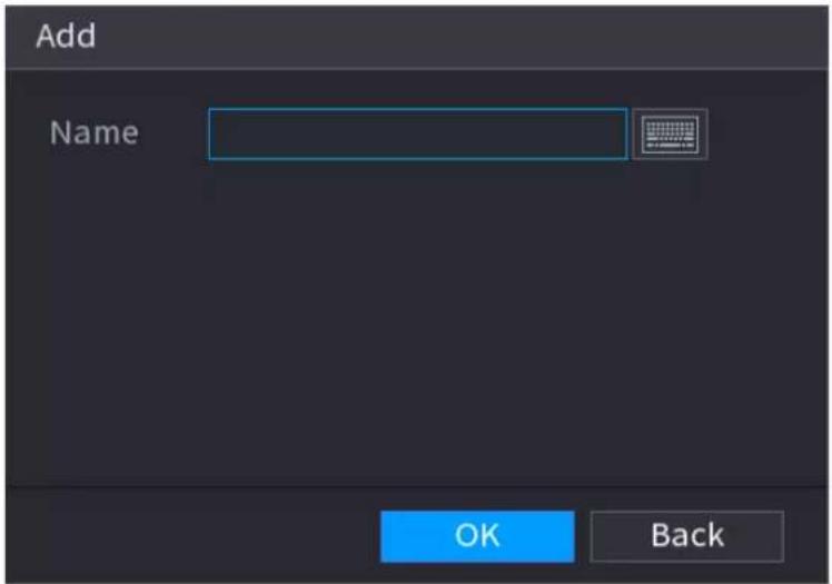
Step 4 Enter the face database name, and then click Save.
- Click to modify database name.

- Click to view the database details and add new faces to the database. For details, see "Adding Face Pictures".
- Select the database, and then click Modeling. The system will extract the attributes of face pictures in the database for the future comparison.
- Select the database, and then click Delete to delete the database.
Figure 5-219 Configure face database
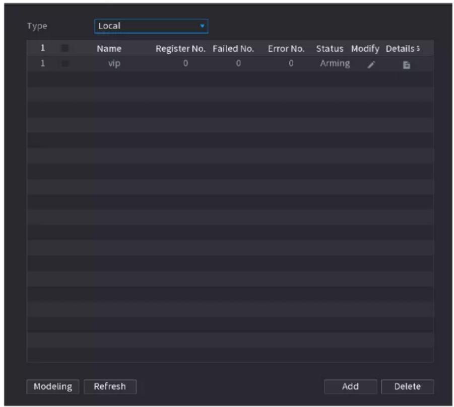
Adding Face Pictures
You can add face pictures to the existing databases one by one or by batch, or add from the detected faces.

To add face pictures one by one or by batch, you need to get the pictures from the USB storage device. The picture size should be smaller than 256K with resolution between 200 × 200–6000 × 5000.
Adding One Face Picture
Step 1 Select Main Menu > AI > Database > Face Database Config.
Step 2 Click of the database that you want to configure.
Figure 5-220 Details
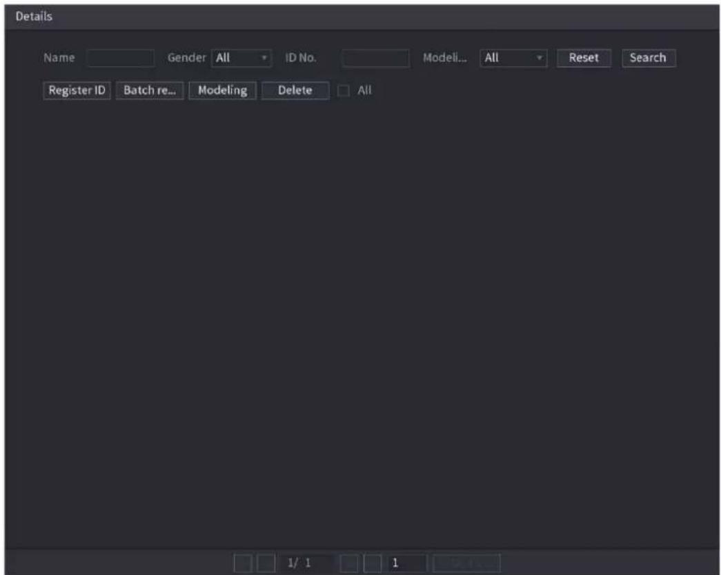
Step 3 Click Register ID.
Figure 5-221 Register ID
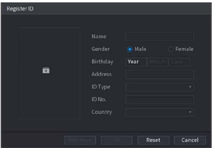
Step 4 Click to add a face picture.
Figure 5-222 Browse
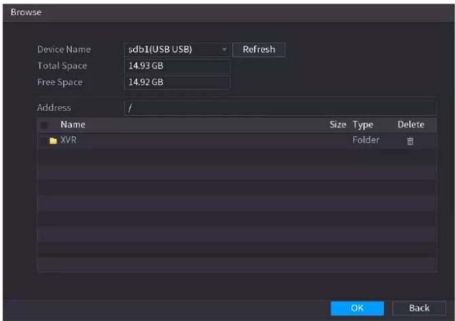
Step 5 Select a face picture and enter the registration information.
Figure 5-223 Register ID
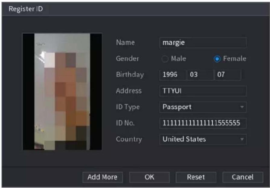
Step 6 Click OK.
The system prompts the registration is successful.
Step 7 On the Details page, click Search.
The system prompts modeling is successful.

If the system prompts the message indicating modeling is in process, wait a while and then click Search again. If modeling is failed, the registered face picture cannot be used for face recognition.
Figure 5-224 Details
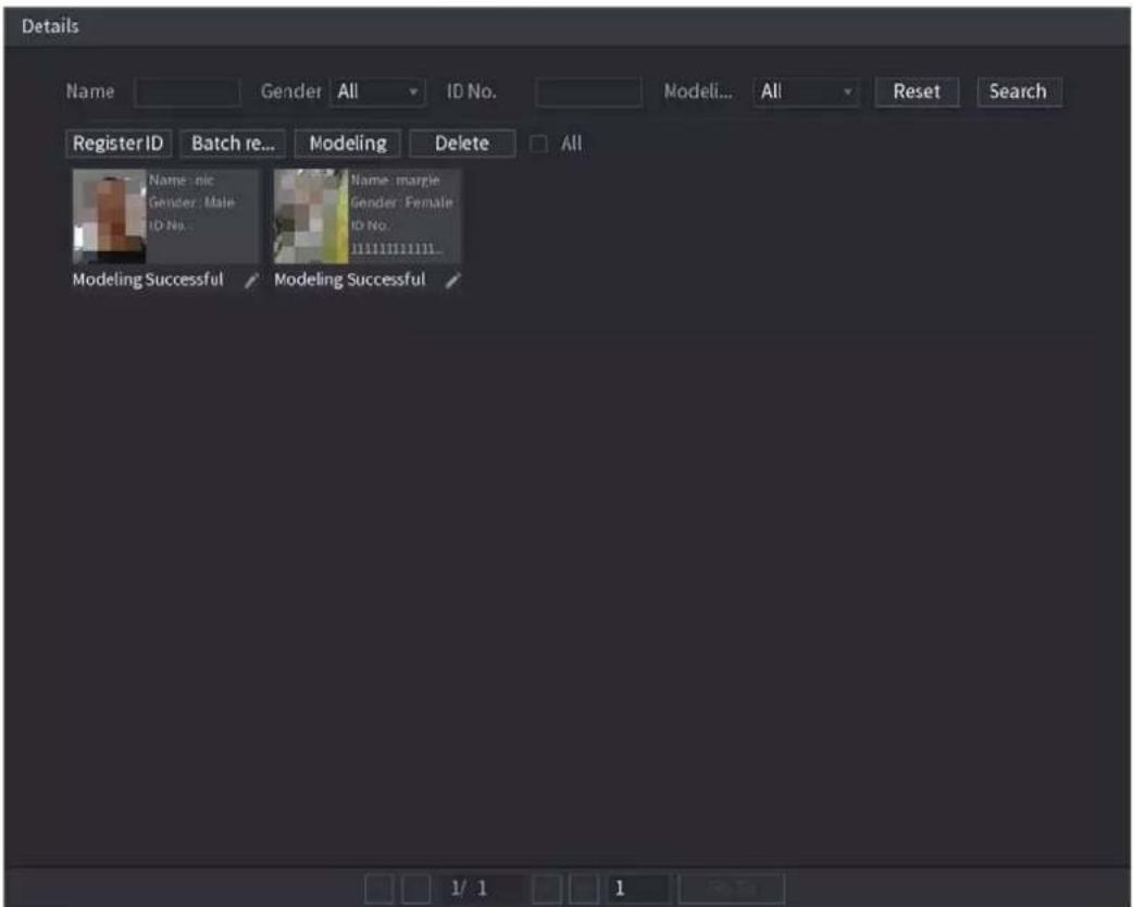
Adding Face Pictures in Batches
Step 1 Give a name to the face picture.
Figure 5-225 Register ID
| Naming format Description | |
| Name Enter the name. | |
| Gender | Enter 1 or 2. 1 represents male, and 2 represents female. |
| Birthday | Enter numbers in the format of yyyy-mm-dd. |
| Country | Enter the abbreviation of country. For example, CN for China. |
| ID Type | 1 represents ID card; 2 represents passport; 3 represents officer password. |
| ID No. Enter the ID number. | |
| Address | Enter the address. |
Step 2 On the Details page, click Batch register.
Figure 5-226 Batch register
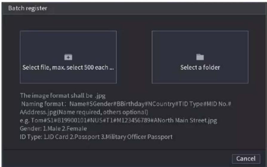
Step 3 Click Select file, max select 500 each time or Select a folder to import face pictures.
Step 4 Click OK to complete batch registration.
Adding the Detected Faces
Step 1 Right-click on the live view screen, and then select Live Mode > AI Mode.
Figure 5-227 AI mode live view
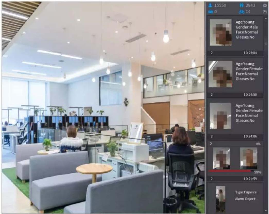
Step 2 Double-click the detected face snapshot that you want to add.
Figure 5-228 Playback
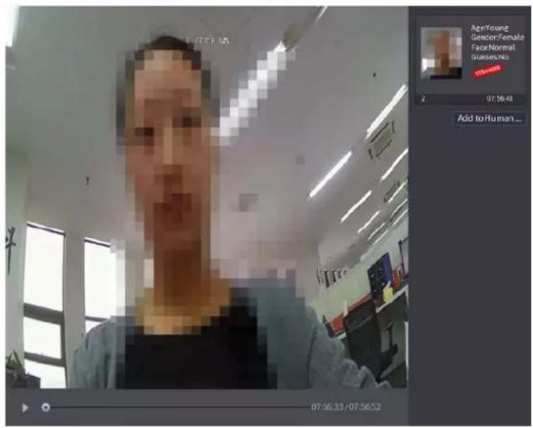
Step 3 Click Add to Human Face Database.
Figure 5-229 Register ID
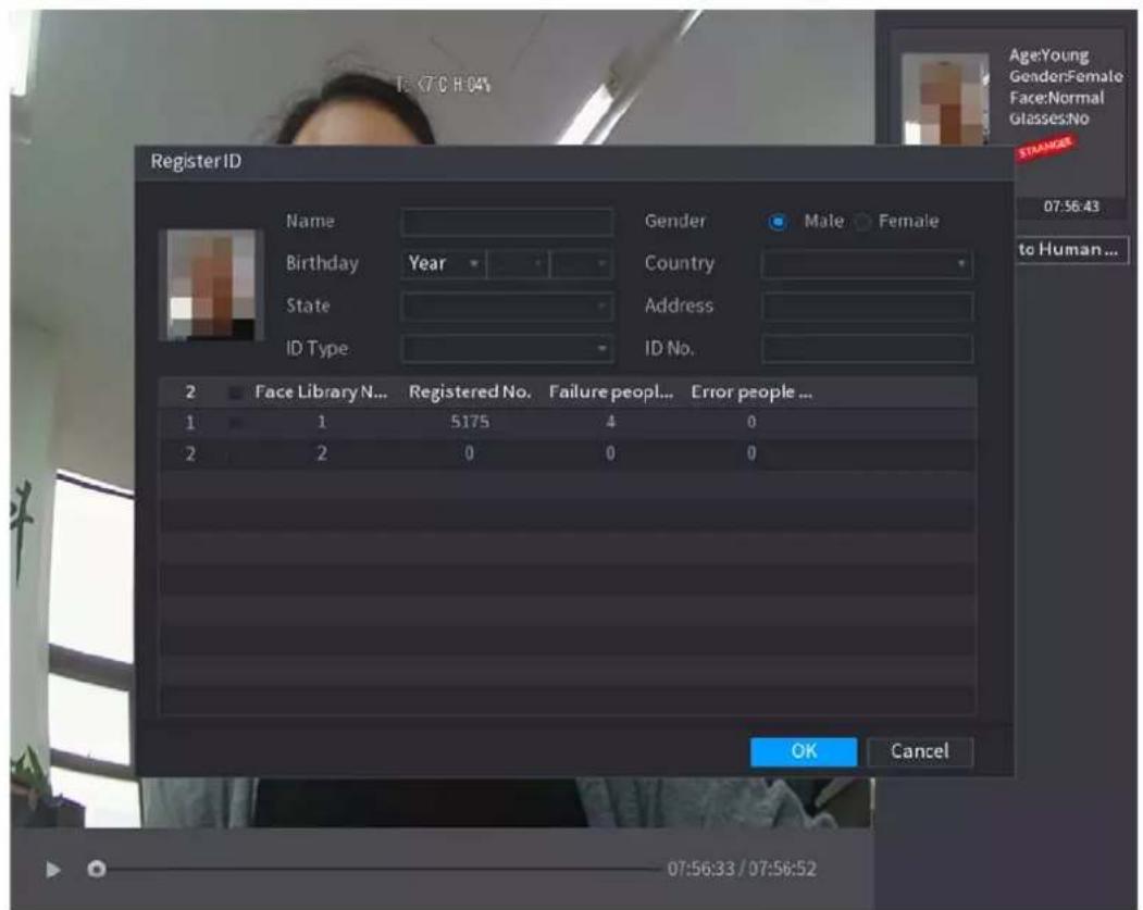
Step 4 Select the face database and enter the ID information.
Step 5 Click OK to complete registration.
5.11.3.4.2 Face Recognition Configuration
You can compare the detected faces with the faces in the database to judge if the detected face belongs to the database. The comparison result will be displayed on the AI mode live view screen and smart search page, and link the alarms.
Step 1 Select Main Menu > AI > Parameters > Face Recognition.
Figure 5-230 Face recognition
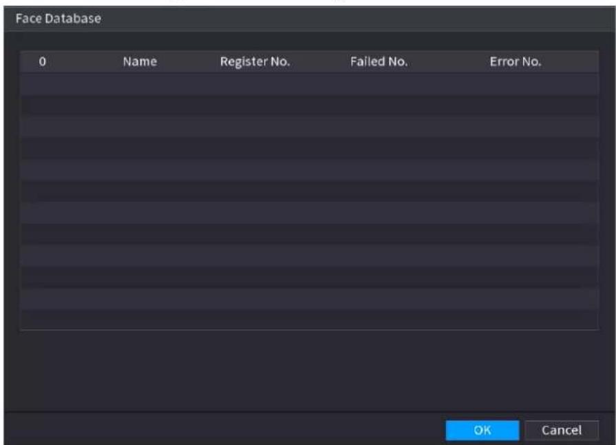
Step 2 In the Channel list, select a channel that you want to configure face recognition function, and then enable it.
Step 3 Set the Period. For details, see "5.10.4.1 Configuring Motion Detection Settings".
Step 4 Set the Target Face Database.
1) Click Setting.
Figure 5-231 Face database
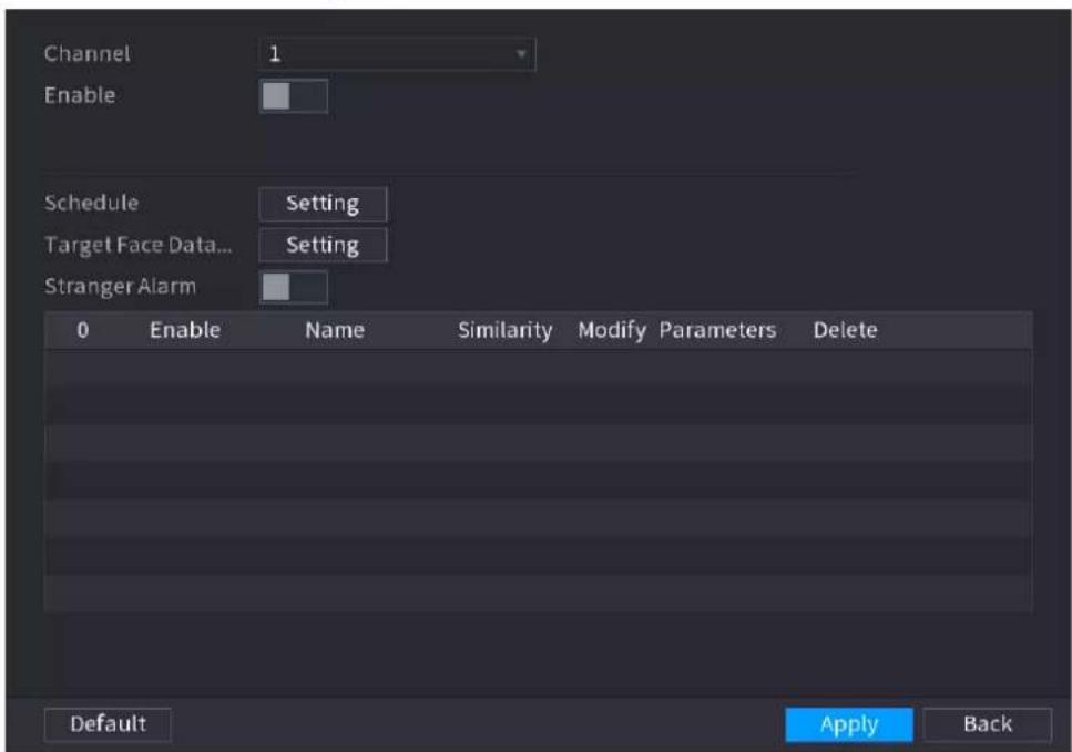
2) Select one or multiple face databases.
3) Click OK.
The selected face database is listed.
Figure 5-232 Database list
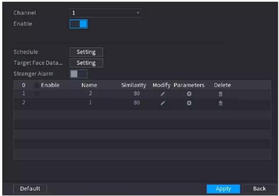
Step 5 Configure the added face database.
- Click to modify the similarity. The lower the number is, the easier the alarm linkage will trigger.
- Click to delete the face database.
- Click ⚙ to set the alarm linkage.
After setting is completed, click OK.
Step 6 (Optional) Enable the Stranger Mode.
1) Enable the Stranger mode (☐). When the detected faces do not belong to the face database, the system remarks the face as "Stranger".
2) Click Setting to set the alarm linkage.
3) After setting is completed, click OK.
Step 7 Click Apply to complete the settings.
After the face recognition function is enabled, right-click on the live view screen, and then select Preview Mode > AI Mode. The AI mode live view screen is displayed.
- If the detected face belongs to the enabled face database, the similarity result is displayed.
- If the detected face does not belong to the enabled face database, the face will be remarked as "Stranger".
Figure 5-233 Similarity result
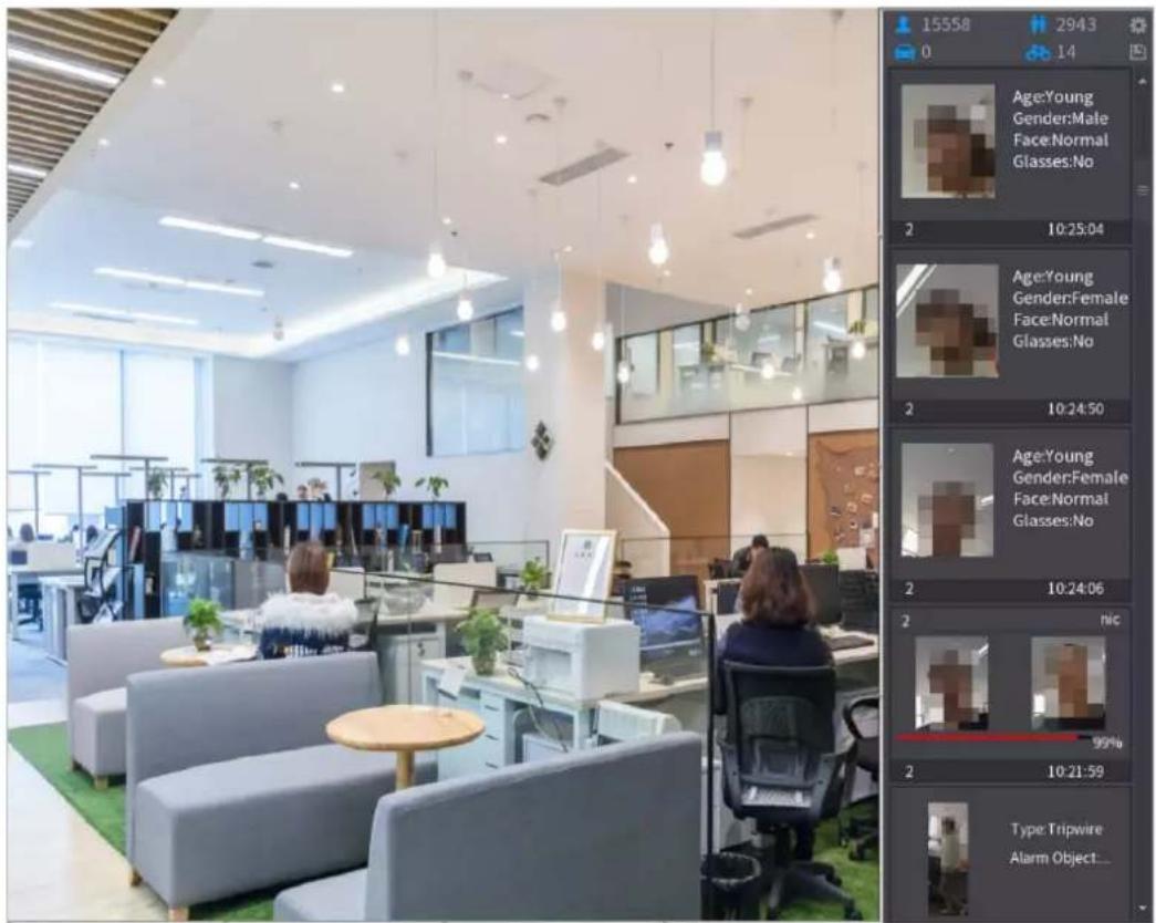
5.11.3.4.3 Smart Search for Face Recognition
You can compare the detected faces with the face database and play back.
- Search by attributes: Search the face database by the face attributes.
- Search by picture: Search the face database by uploading face pictures.
Searching by Attributes
Step 1 Select Main Menu > AI > AI Search > Face Recognition > Search by Attributes.
Figure 5-234 Search by attributes
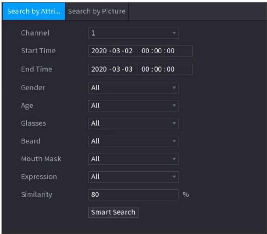
Step 2 Select the channel and set the parameters such as start time, end time, gender, age, glasses, beard, mask, and similarity according to your requirement.
Step 3 Click Smart Search.
Figure 5-235 Search results
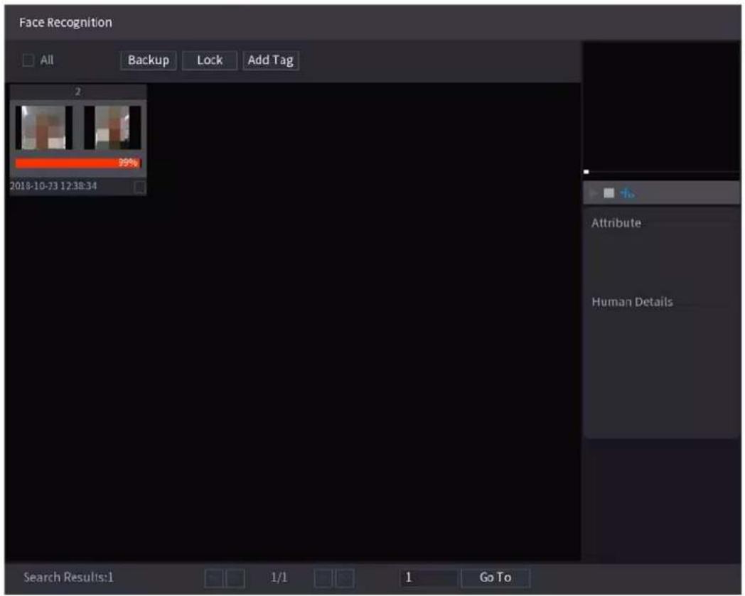
Step 4 Click the picture that you want to play back.
The picture with registered information is displayed.
Figure 5-236 Registered information
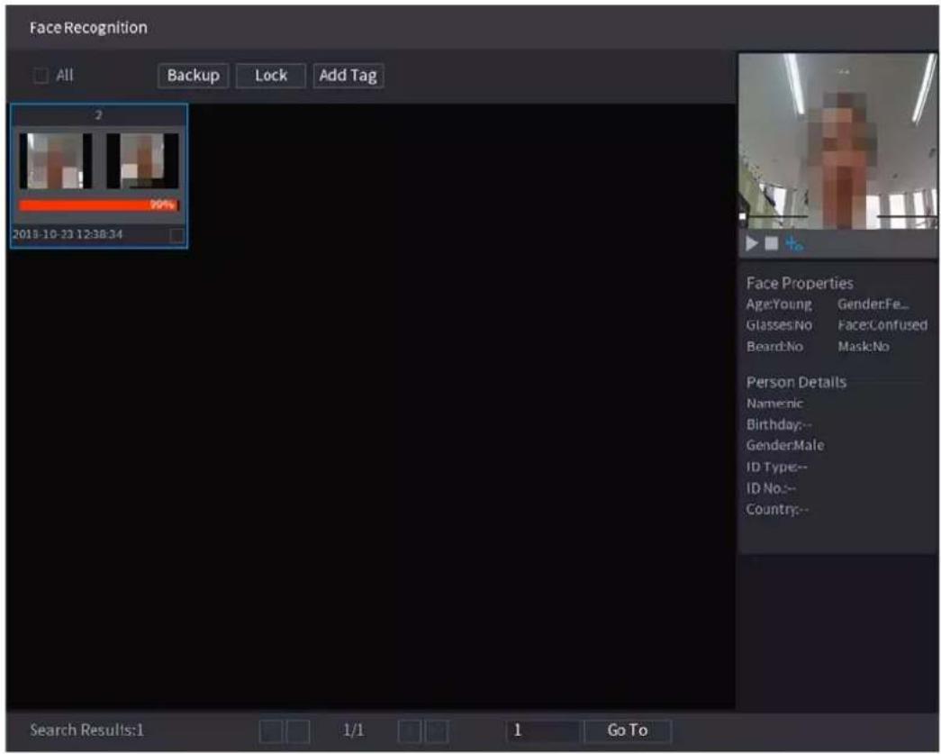
Step 5
Click

to play back the recorded video.

Double-click on the playing page to switch between full screen playing and thumbnail playing.
You can also do the following operations to the recorded files.
- To export the database file (.csv) to the external storage device, select files, click Export, and then select the save path.
- To back up the recorded files to the external storage device, select files, click Backup, select the save path and file type, and then click Start.
Figure 5-237 Backup
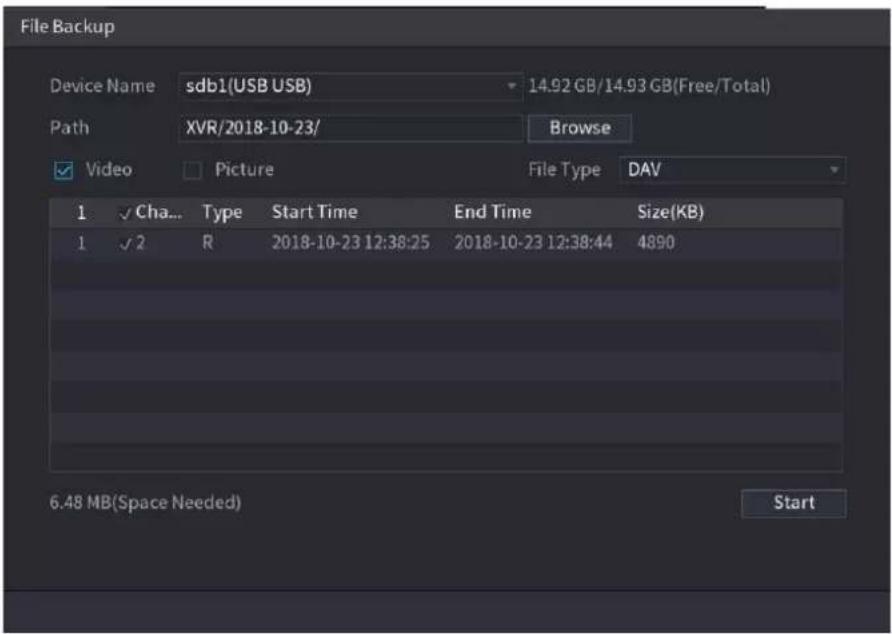
- To lock the files to make it unable to be overwritten, select the files, and then click Lock.
• To add a mark to the file, select the files and then click Add Mark.
Search by Picture
Step 1 Select Main Menu > AI > AI Search > Face Recognition > Search by Picture.
Figure 5-238 Search by picture
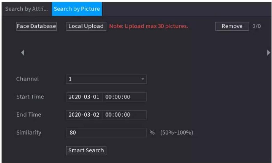
Step 2 Upload face pictures from Face Database or Local Upload.

Maximum 30 pictures can be uploaded at one time, and the system support searching 8 pictures at one time.
- Face Database
1) Click Face Database.
Figure 5-239 Face database
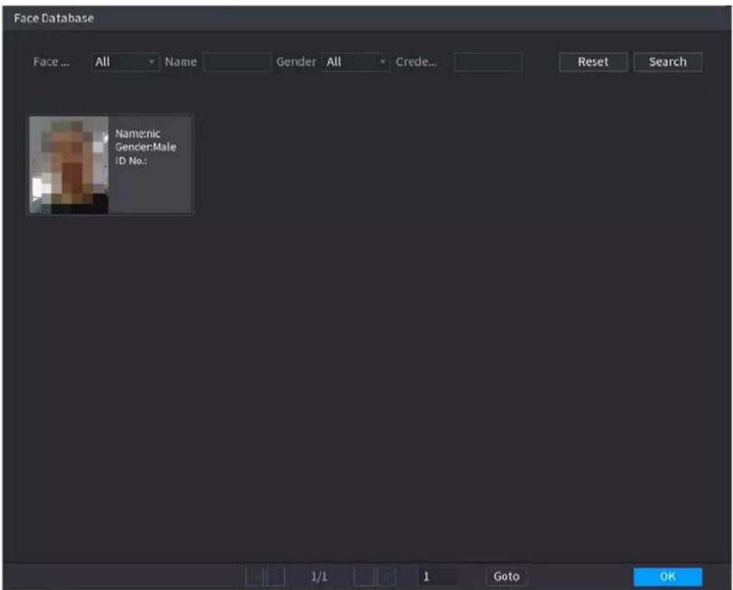
2) Set the searching parameters by selecting the face database and gender, and entering name and ID No. according to your actual requirement.
3) Click Search to display the results that satisfy the requirement.

Click Reset to clear the searching parameters.
4) Select the picture and then click Save.
Figure 5-240 Search by picture
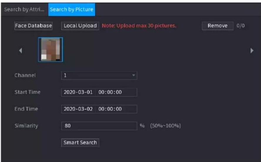
- Local Upload
Plug the USB storage device (with face pictures) to the Device, and then click Local Upload. Then select the picture from the USB storage device, and then click OK. The selected face pictures are uploaded.
Step 3 After the face pictures are uploaded, continue to configure other parameters (channel, start time, end time, and similarity).
Step 4 Click Smart Search.
Figure 5-241 Search results
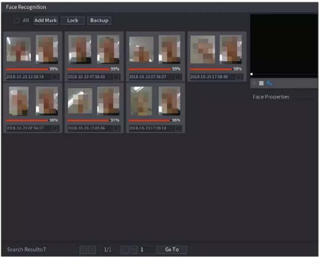
Step 5 Select the face picture that you want to play back.
Figure 5-242 Playback
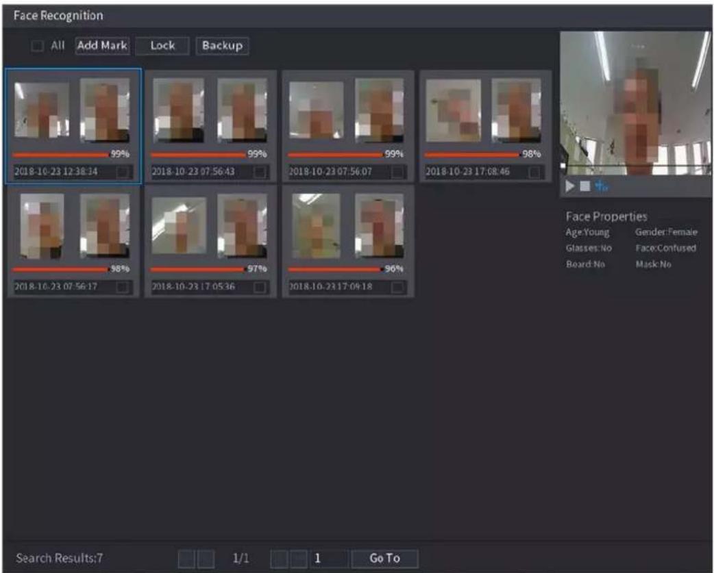
Step 6
Click

to play back the recorded video.

Double-click on the playing page to switch between full screen playing and thumbnail playing.
You can also do the following operations to the recorded files.
• To add a mark to the file, select the files and then click Add Mark.
- To lock the files to make it unable to be overwritten, select the files, and then click Lock.
- To back up the recorded files to the external storage device, select files, click Backup, select the save path and file type, and then click Start.
Figure 5-243 Backup
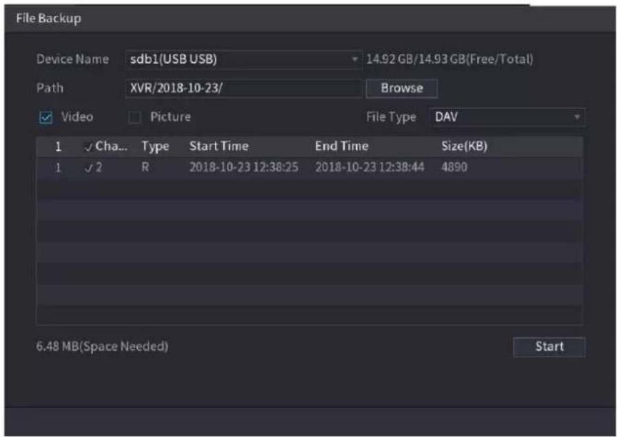
5.11.4 Configuring IVS Mode
For some models, you can switch the IVS function between general mode and advanced mode in Main Menu > AI > Parameters > IVS. The advanced mode features higher detection accuracy than the general mode but supports fewer channels for IVS. The function might vary depending on the model.
Figure 5-244 IVS mode
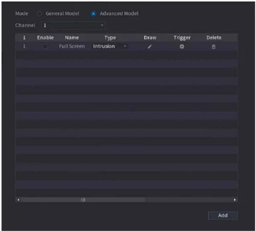
5.11.5 Configuring Smart Schedule
There are two modes for a channel to activate AI functions.
- General mode: Only one AI function can be enabled for the designated channel during different periods on each day in the week.
- Schedule mode: The system can activate different AI functions for the designated channel during different periods on each day in the week.
This section introduces how to enable the schedule mode.
Step 1 Select Main Menu > AI > Parameters > Intelligent Mode.
Figure 5-245 Schedule mode
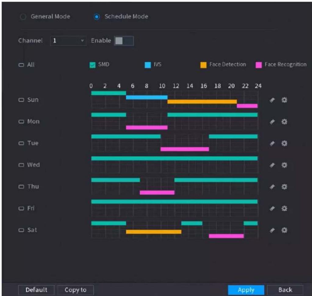
bar
| Day | SMD | IVS | Face Detection | Face Recognition | |-------|-----|-----|----------------|------------------| | Sun | 5 | 10 | 21 | 22 | | Mon | 12 | 0 | 0 | 11 | | Tue | 24 | 0 | 0 | 17 | | Wed | 24 | 0 | 0 | 0 | | Thu | 12 | 0 | 0 | 8 | | Fri | 24 | 0 | 0 | 0 | | Sat | 12 | 0 | 13 | 16 |Step 2 Select Schedule Mode.

The configurations of AI functions in the general mode and schedule mode are independent. The changes you make in one mode does not affect the configurations in the other mode.
Step 3 Select one channel and then click

Step 4 Define the periods for AI functions.
- Define the period by drawing.
1) Select the checkbox of AI function.
Figure 5-246 AI function

2) On the timeline, drag to define a period.
You can set up to 6 periods for each day in the week. For each period, you can enable an AI function.
- Define the period by editing.
1) Click.

Figure 5-247 Period
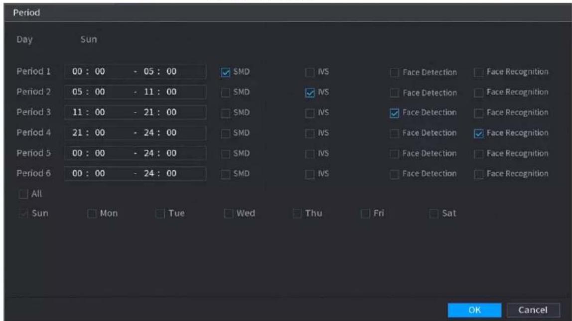
2) Configure the time range for each period and then select the AI function to be effective during each period.

You can select All to apply the settings to all the days in the week, or select specific days that you want to apply the settings to
3) Click OK.
Step 5 Click Apply.
5.12 IoT Function
5.12.1 Configuring Sensor Settings
You can connect external sensors wirelessly through the Device with USB gateway or through connecting to a camera gateway. After connection, you can activate alarm events through external sensors.
5.12.1.1 Connecting Sensor through Device

Only the Device with USB gateway supports this function.
Step 1 Select Main Menu > IoT > Management > Sensor Pairing.
Figure 5-248 Sensor pairing
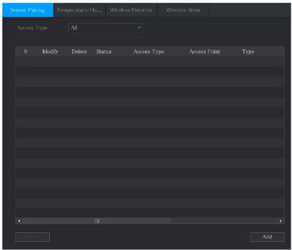
Step 2 In the Access Type list, select USB Gateway.
Step 3 Click Add.
Figure 5-249 Add USB gateway
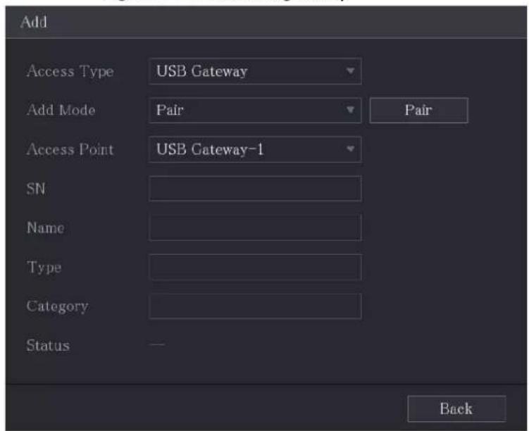
Step 4 Click Pair.
Figure 5-250 Pair
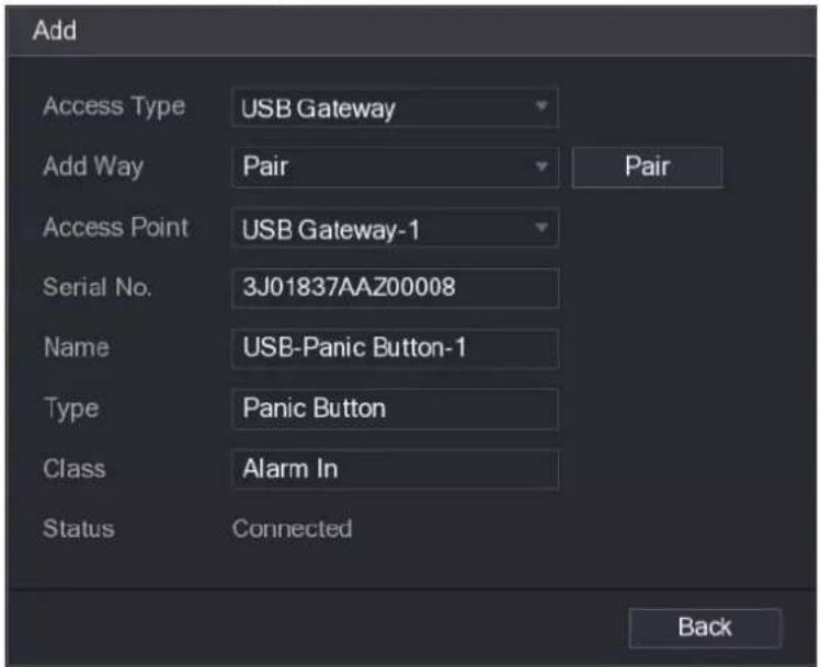
Step 5 Click Back to exit the pairing page.
The added sensor information is displayed.


Figure 5-251 Sensor pairing
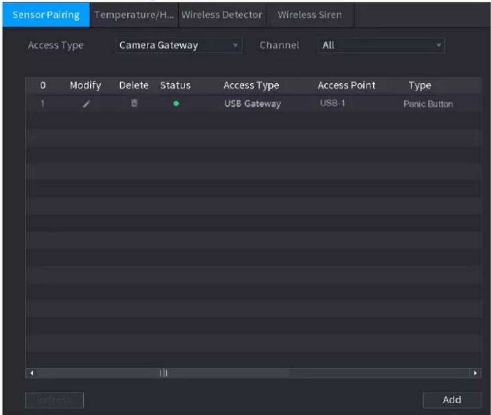
5.12.1.2 Connecting Sensor through Camera with Gateway

Only the camera with gateway supports this function.
Step 1 Select Main Menu > IoT > Management > Sensor Pairing.
Figure 5-252 Sensor pairing
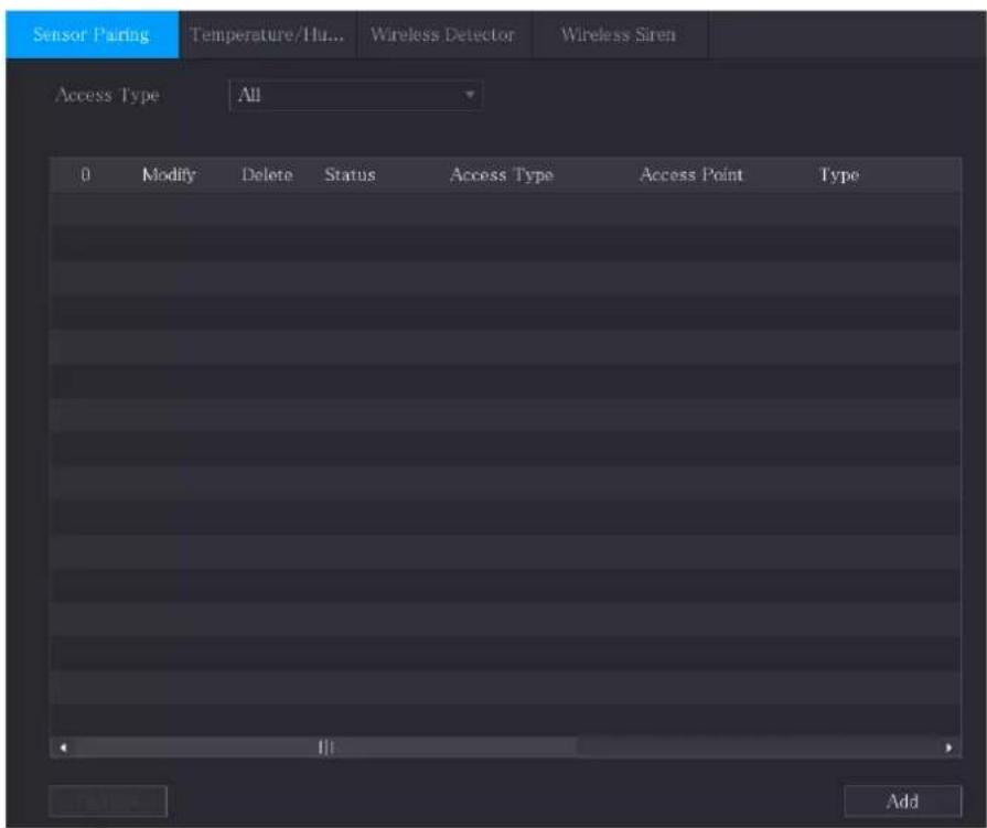
Step 2 In the Access Type list, select Camera Gateway.
Step 3 In the Channel list, select the channel that is connected to the camera.
Step 4 Click Add.
Figure 5-253 Add camera gateway
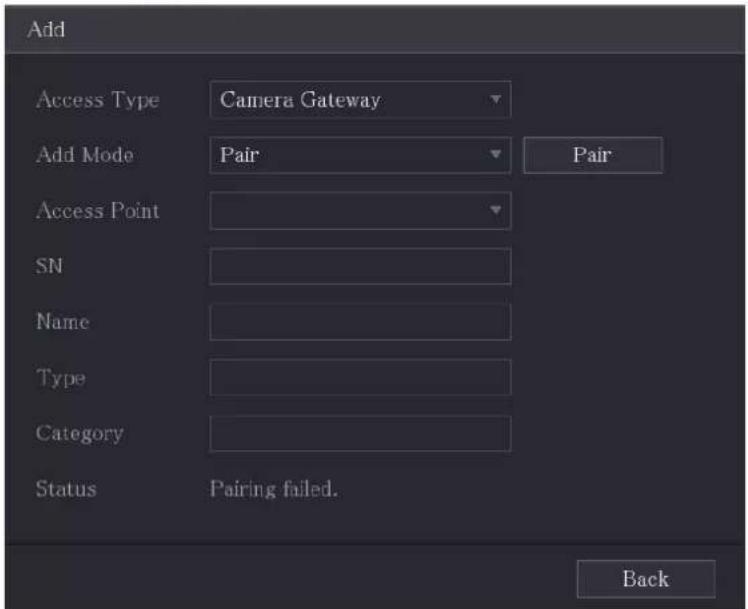
Step 5 Click Pair.
Figure 5-254 Pair
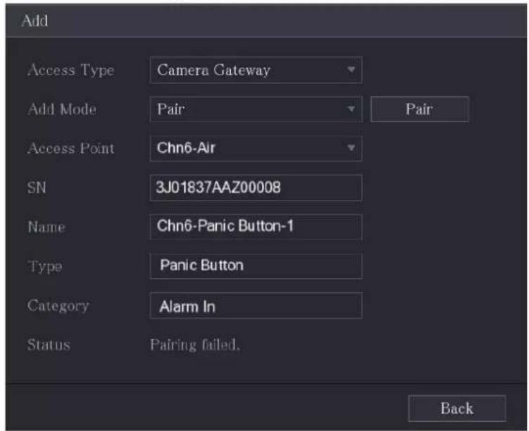
Step 6 Click Back to exit the pairing page.


Figure 5-255 Sensor pairing
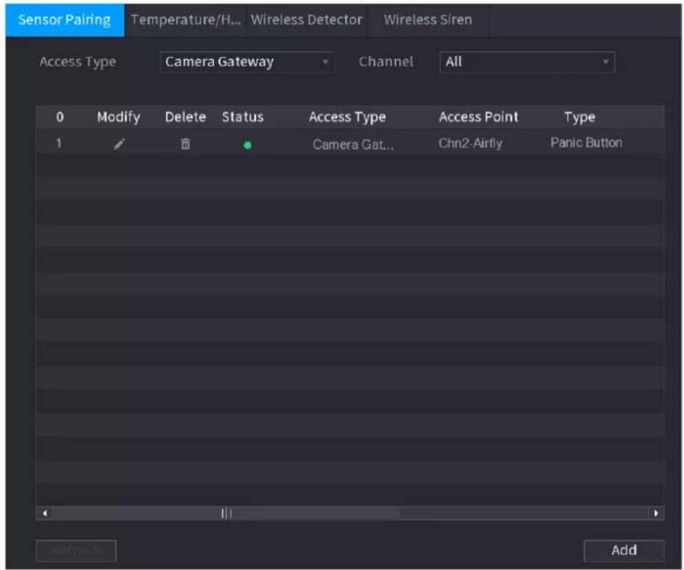
5.12.1.3 Configuring Alarm Linkage
Step 1 Select Main Menu > IoT > Management > Wireless Detector.
Figure 5-256 Wireless detector
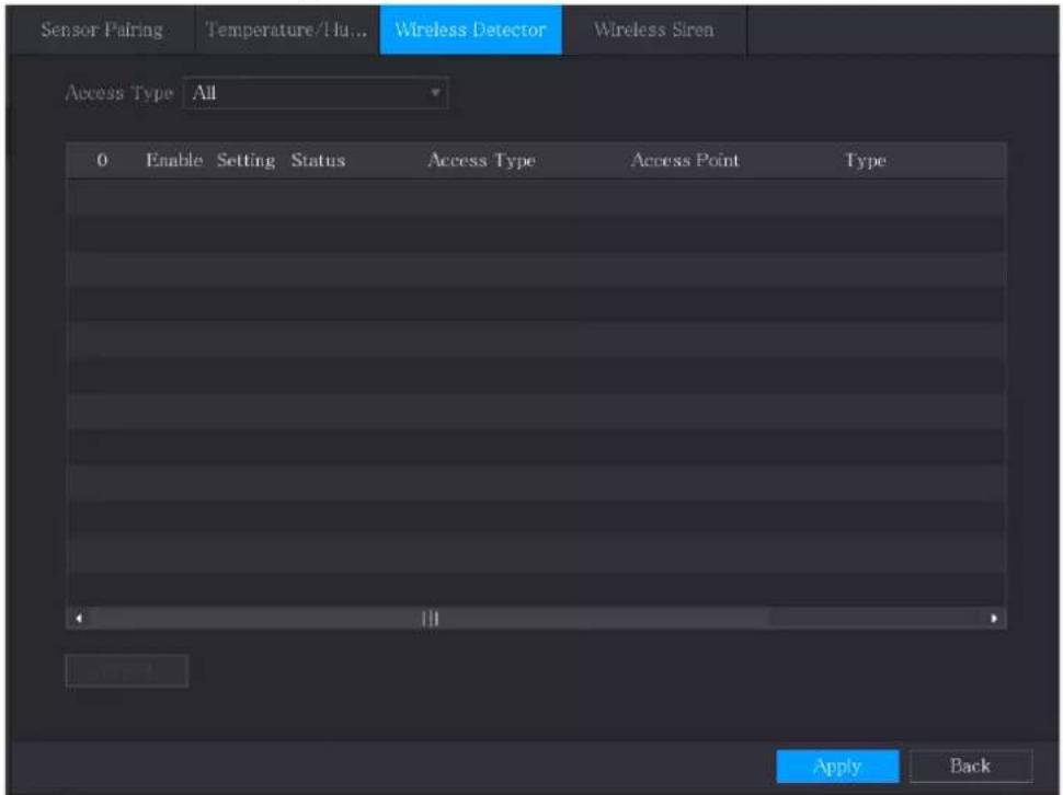
Step 2 In the Access Type list, select USB Gateway, Camera Gateway, or All.

When Access Type is Camera Gateway, you can select Channel to filter the status of present wireless detector.
Step 3 Click.

Figure 5-257 Setting
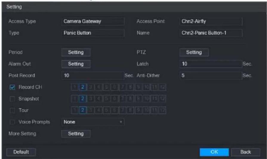
Step 4 Configure the settings for alarm linkage.
Table 5-39 Alarm linkage settings
| Parameter Description | |
| Name | Enter the customized alarm name. |
| Parameter Description | |
| Schedule | ClickSettingto configure the parameters.Define a period during which the motion detection is active. For details, see "Setting Motion Detection Period" section in "5.10.4.1 Configuring Motion Detection Settings". |
| PTZ Linkage | ClickSettingto display the PTZ page.Enable PTZ linkage actions, such as selecting the preset that you want to be called when an alarm event occurs. |
| Alarm-out Port | ClickSettingto configure the parameters.Local Alarm: Enable alarm activation through the alarm devices connected to the selected output port.Extension Alarm: Enable alarm activation through the connected alarm box.Wireless Siren: Enable alarm activation through devices connected by USB gateway or camera gateway. |
| Post-Alarm | Set a length of time for the Device to delay turning off alarm after the external alarm is cancelled. The value ranges from 0 seconds to 300 seconds, and the default value is 10 seconds. |
| Post Record | Set a length of time for the Device to delay turning off recording after the alarm is cancelled. The value ranges from 10 seconds to 300 seconds, and the default value is 10 seconds. |
| Anti-Dither | Configure the time period from end of event detection to the stop of alarm. |
| Record Channel | Select the channel(s) that you want to record. The selected channel(s) starts recording after an alarm event occurs.The recording for alarm and auto recording must be enabled. For details, see "5.1.4.9 Configuring Recorded Video Storage Schedule" and "5.9.1 Enabling Record Control". |
| Snapshot | Select theSnapshotcheckbox to take a snapshot of the selected channel.To use this function, selectMain Menu >CAMERA >Encode >Snapshot, in theTypelist, selectEvent. |
| Tour | Select theTourcheckbox to enable a tour of the selected channels. |
| Alarm Tone | Select to enable audio broadcast/voice prompts in response to a local alarm event. |
| Parameter Description | |
| More Setting | Show Message: Select the Show Message checkbox to enable a pop-up message in your local host PC.Buzzer: Select the checkbox to activate a buzzer noise at the Device.Video Matrix: Select the checkbox to enable the function. When an alarm event occurs, the video output port outputs the settings configured in Main Menu > DISPLAY > Tour. This function is available on select models.Send Email: Enable the system to send an email notification when an alarm event occurs. This function is available on select models.Send Email: Enable the system to send an email notification when an alarm event occurs. To use this function, make sure the email function is enabled in Main Menu > NETWORK > Email.Log: Select the checkbox to enable the Device to record a local alarm log.Extra screen: Select the checkbox to enable the function. When an alarm event occurs, the extra screen outputs the settings configured in Main Menu > DISPLAY > Tour > Sub Screen. To use this function, make sure the email function is enabled in Main Menu > NETWORK > Email.Log: Select the checkbox to enable the Device to record a local alarm log.Extra screen: Select the checkbox to enable the function. When an alarm event occurs, the extra screen outputs the settings configured in Main Menu > DISPLAY > Tour > Sub Screen. This function is available on select models.To use this function, extra screen shall be enabled. This function is available on select models.To use this function, extra screen shall be enabled. |
Step 5 Click OK to save the settings.
Step 6 On the Wireless Detector page, click Apply to complete the settings.
5.12.2 Configuring Temperature and Humidity Camera
You can view, search and export the temperature and humidity data of camera with such sensors and configure the alarm event settings.
To use this function, make sure there is at least one camera with temperature and humidity sensor has been connected to the Device.
5.12.2.1 Enabling Detecting Function
You should enable the IoT function the first time when you enter this page.
Step 1 On the main menu, select IoT > Management > Temperature/Humidity.
Figure 5-258 Temperature/Humidity
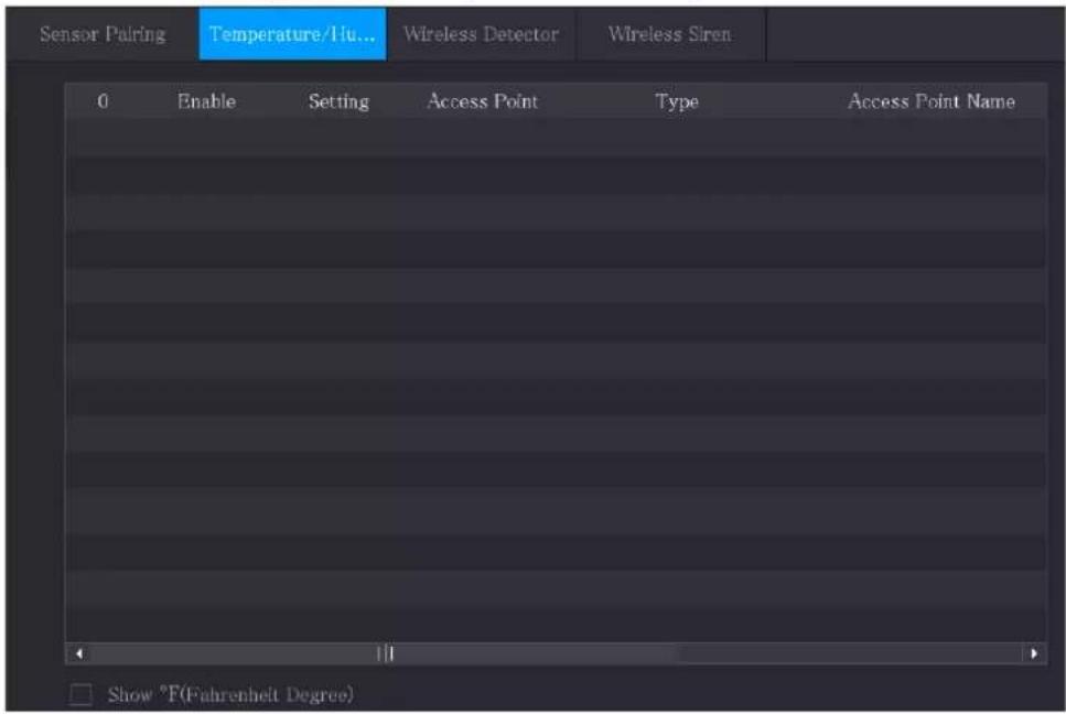
Step 2 Select the Enable checkboxes to enable IoT function.
Figure 5-259 Enable
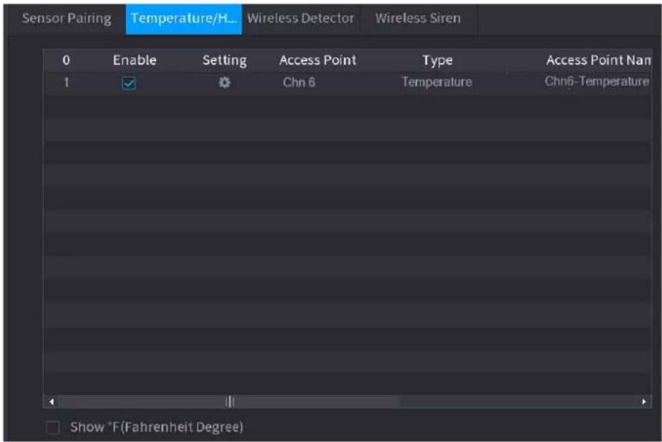
The Device starts detecting the temperature and humidity data from the camera and display on the Realtime Display page.
Step 3 (Optional) Set temperature displaying mode.
When Show°F (Fahrenheit Degree) is selected, the temperature will be displayed by Fahrenheit degree in Realtime Display tab.
5.12.2.2 Viewing Temperature and Humidity Data
You can view the temperature and humidity data on the Realtime Display page after the IoT function is enabled.
In the Refresh Interval box, select data refresh interval. For example, you can select 5 Sec.
You can also display the temperature and humidity data in graphical way by selecting the Display Chart checkbox.
Figure 5-260 Chart
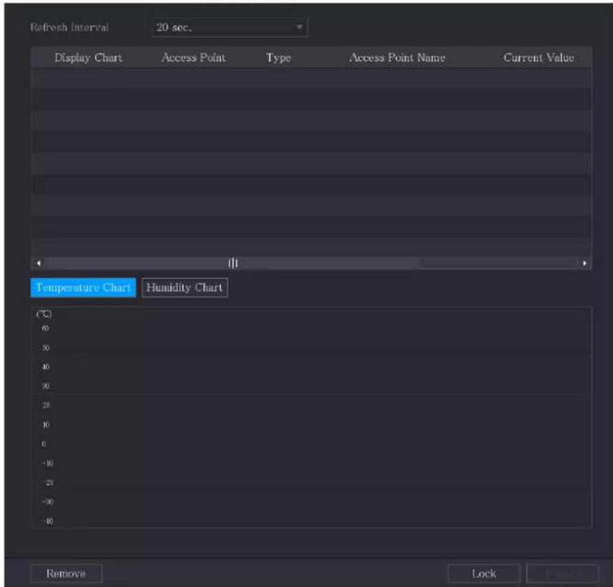

Click Remove to delete the data.
5.12.2.3 Exporting Temperature and Humidity Data
You can export the temperature and humidity data in .BMP format. This section uses exporting humidity data as an example.
Step 1 Prepare a USB device and plug it into the Device.
Step 2 On the Realtime Display page, click the Humidity tab.
Figure 5-261 Humidity
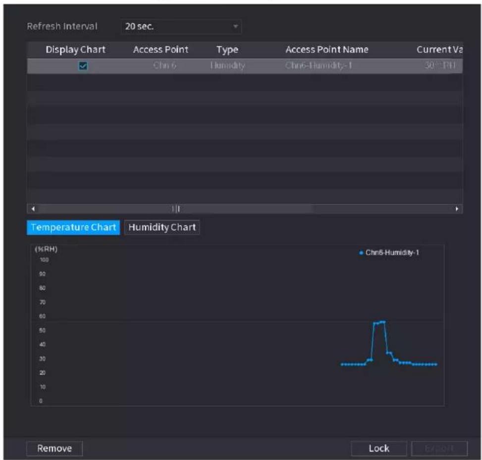
line
| Time | Change (%) | |------|------------| | 0 | 0 | | 30 | 25 | | 60 | 55 | | 90 | 25 | | 120 | 25 |Step 3 Click Lock to lock the data.
The export button is enabled.
Step 4 Click Export. The system starts exporting the data.
Step 5 Click OK.
You can find the exported data on your USB device.
5.12.2.4 Configuring Alarm Linkage
You can configure alarm linkage settings for temperature and humidity data.
5.12.2.4.1 Configuring Alarm Linkage for Temperature Data
Step 1 On the home page, select IoT > Management > Temperature/Humidity.
Figure 5-262 Temperature/Humidity
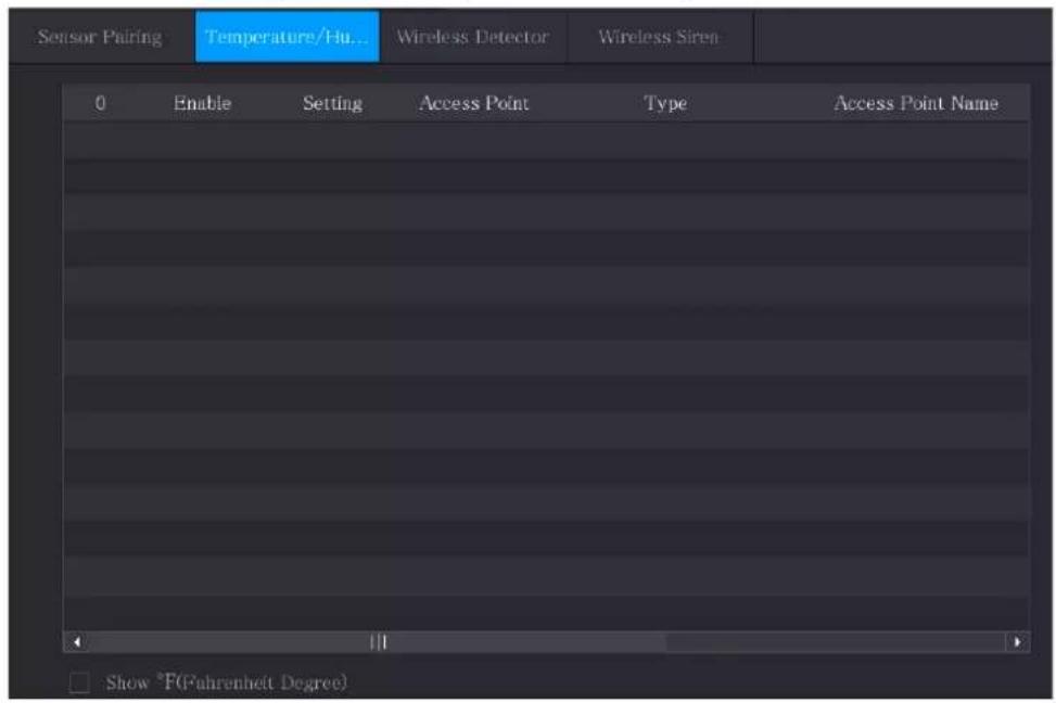
Step 2 On the temperature information line, click .

Figure 5-263 Setting
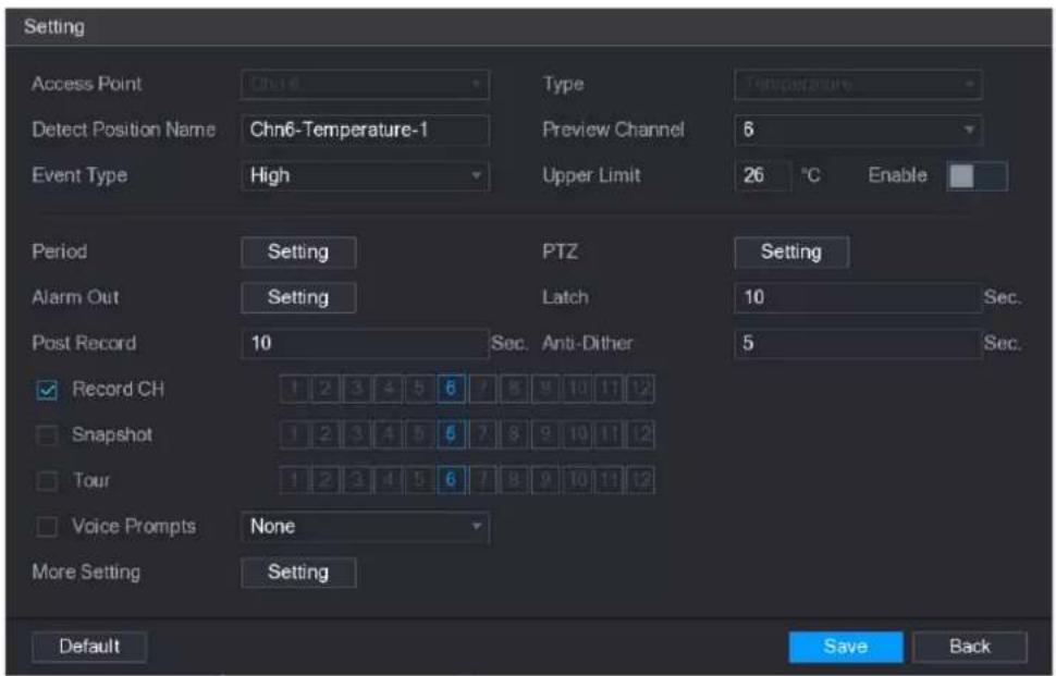
Step 3 Configure the settings for alarm linkage.
Table 5-40 Alarm linkage settings
| Parameter Description | |
| Access Point | Indicates the channel that the camera is connected to. |
| Type | Temperature by default. |
| Detect Position Name Set the detect position name. | |
| Preview Channel | Select the channel that you want to preview to help monitor the channel of access point. This channel could be the channel of access point or any other channels according to your actual situation. |
| Event Type | Select event type asHighorLow, and set the upper and low temperature limit respectively. For example, select event type asHighand set upper limit as28, the alarm occurs when the temperature reaches 28 °C. |
| Upper Limit | |
| Enable Enable the alarm function. | |
| Schedule | Define a period during which the alarm setting is active. For more information about setting the period, see "5.10.4.1 Configuring Motion Detection Settings". |
| Alarm-out Port | ClickSettingto configure the parameters.General Alarm: Enable alarm activation through the alarm devices connected to the selected output port.External Alarm: Enable alarm activation through the connected alarm box.Wireless Siren: Enable alarm activation through devices connected by USB gateway or camera gateway. |
| PTZ Linkage | ClickSettingto display the PTZ page.Enable PTZ linkage actions, such as selecting the preset that you want to be called when an alarm event occurs. |
| Post-Alarm | Set a length of time for the Device to delay turning off alarm after the external alarm is cancelled. The value ranges from 0 seconds to 300 seconds, and the default value is 10 seconds. If you enter 0, there will be no delay. |
| Post Record | Set a length of time for the Device to delay turning off recording after the alarm is cancelled. The value ranges from 10 seconds to 300 seconds, and the default value is 10 seconds. |
| Anti-Dither | Configure the time period from end of event detection to the stop of alarm. |
| Snapshot | Select the checkbox to take a snapshot of the selected channel.To use this function, make sure the snapshot is enabled motion detect alarms inMain Menu > STORAGE > Schedule > Snapshot. |
| Record Channel | Select the channel(s) that you want to record. The selected channel(s) starts recording after an alarm occurs.The recording for IoT alarms and auto recording function must be enabled. For details, see "5.1.4.9 Configuring Recorded Video Storage Schedule" and "5.9.1 Enabling Record Control". |
| Tour | Select the checkbox to enable a tour of the selected channels.To use this function, make sure the tour is enabled and configured inMain Menu > DISPLAY > Tour. |
| Alarm Tone | Select to enable audio broadcast/alarm tones in response to a temperature alarm event. |
| More Setting | ● Show Message: Select theShow Messagecheckbox to enable a pop-up message in your local host PC.● Buzzer: Select the checkbox to activate a buzzer noise at the Device.● Video Matrix: Select the checkbox to enable the function. When an alarm event occurs, the video output port outputs the settings configured inMain Menu > DISPLAY > Tour. This function is available on select models.● Send Email: Enable the system to send an email notification when an alarm event occurs. This function is available on select models.● Send Email: Enable the system to send an email notification when an alarm event occurs. To use this function, make sure the email function is enabled inMain Menu > NETWORK > Email.● Log: Select the checkbox to enable the Device to record a local alarm log.● Extra screen: Select the checkbox to enable the function. When an alarm event occurs, the extra screen outputs the settings configured inMain Menu > DISPLAY > Tour > Sub Screen. To use this function, make sure the email function is enabled inMain Menu > NETWORK > Email.● Log: Select the checkbox to enable the Device to record a local alarm log.● Extra screen: Select the checkbox to enable the function. When an alarm event occurs, the extra screen outputs the settings configured inMain Menu > DISPLAY > Tour > Sub Screen. ● This function is available on select models.● To use this function, extra screen shall be enabled. ● This function is available on select models.● To use this function, extra screen shall be enabled. |
Step 4 Click Save to save the settings.
5.12.2.4.2 Configuring Alarm Settings for Humidity Data
You can configure the alarm event by setting the humidity data.
Step 1 On the home page, select IoT > Management > Temperature/Humidity.
Figure 5-264 Temperature/Humidity
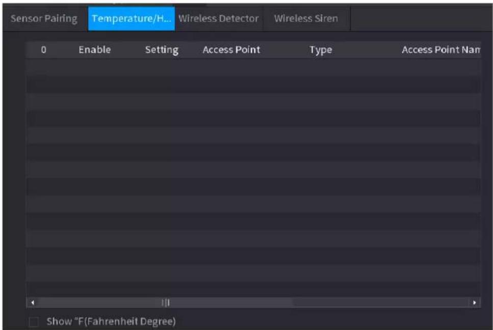
Step 2 On the humidity information line, click .

Figure 5-265 Setting
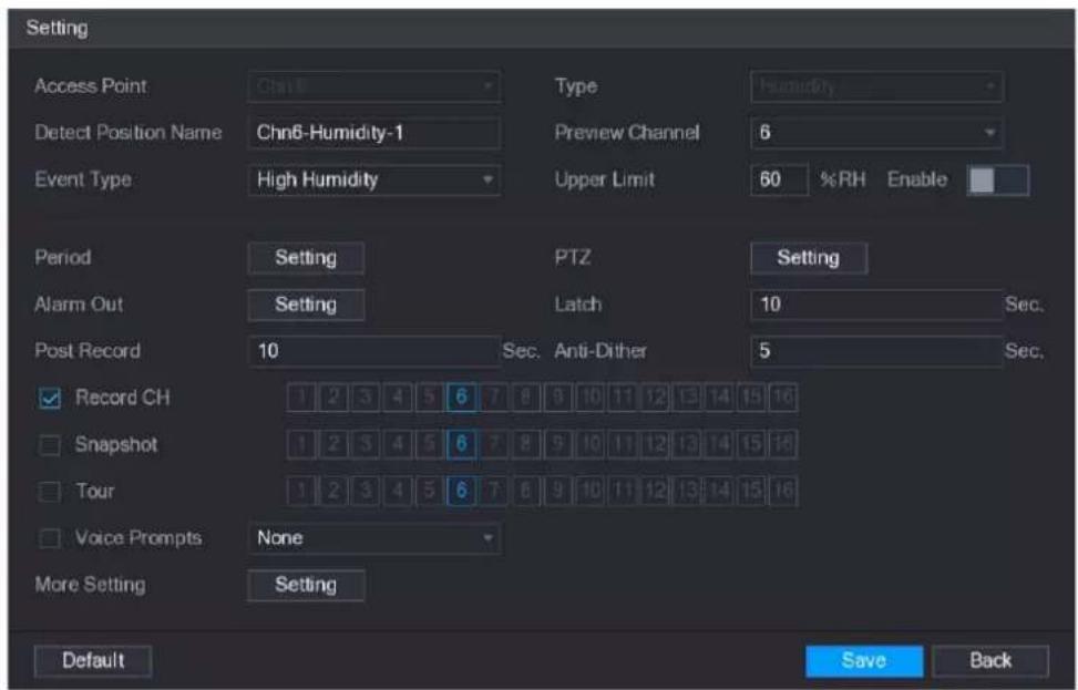
Step 3 Configure the settings for the following parameters.
Table 5-41 Alarm settings
| Parameter Description | |
| Access Point | Indicates the channel that the camera is connected to. |
| Type | Humidity by default. |
| Detect Position Name Set the detect position name. | |
| Preview Channel | Select the channel that you want to preview to help monitor the channel of access point. This channel could be the channel of access point or any other channels according to your actual situation. |
| Event Type | Select event type as High Humidity or Low Humidity, and set the upper and low humidity limit respectively. For example, select event type as High Humidity and set upper limit as 60, the alarm occurs when the humidity reaches 60%RH. |
| Upper Limit | |
| Enable Enable the alarm function. | |
| Schedule | Define a period during which the alarm setting is active. For more information about setting the period, see "5.10.4.1 Configuring Motion Detection Settings". |
| Alarm-out Port | Click Setting to configure the parameters.General Alarm: Enable alarm activation through the alarm devices connected to the selected output port.External Alarm: Enable alarm activation through the connected alarm box.Wireless Siren: Enable alarm activation through devices connected by USB gateway or camera gateway. |
| PTZ Linkage | ClickSettingto display the PTZ page.Enable PTZ linkage actions, such as selecting the preset that you want to be called when an alarm event occurs. |
| Post-Alarm | Set a length of time for the Device to delay turning off alarm after the external alarm is cancelled. The value ranges from 0 seconds to 300 seconds, and the default value is 10 seconds. If you enter 0, there will be no delay. |
| Post Record | Set a length of time for the Device to delay turning off recording after the alarm is cancelled. The value ranges from 10 seconds to 300 seconds, and the default value is 10 seconds. |
| Anti-Dither | Configure the time period from end of event detection to the stop of alarm. |
| Snapshot | Select the checkbox to take a snapshot of the selected channel.To use this function, make sure the snapshot is enabled motion detect alarms inMain Menu > STORAGE > Schedule > Snapshot. |
| Record Channel | Select the channel(s) that you want to record. The selected channel(s) starts recording after an alarm occurs.The recording for IoT alarms and auto recording function must be enabled. For details, see "5.1.4.9 Configuring Recorded Video Storage Schedule" and "5.9.1 Enabling Record Control". |
| Tour | Select the checkbox to enable a tour of the selected channels.To use this function, make sure the tour is enabled and configured inMain Menu > DISPLAY > Tour. |
| Alarm Tone | Select to enable audio broadcast/voice prompts in response to a temperature alarm event. |
| More Setting | Show Message: Select theShow Messagecheckbox to enable a pop-up message in your local host PC.Buzzer: Select the checkbox to activate a buzzer noise at the Device.Video Matrix: Select the checkbox to enable the function. When an alarm event occurs, the video output port outputs the settings configured inMain Menu > DISPLAY > Tour.This function is available on select models.Send Email: Enable the system to send an email notification when an alarm event occurs.To use this function, make sure the email function is enabled inMain Menu > NETWORK > Email.Log: Select the checkbox to enable the Device to record a local alarm log. |
Step 4 Click Save to save the settings.
5.12.2.5 Searching IoT Information
You can search and backup all your IoT data.
To back up the data, you should prepare a USB device and plug it into the Device.
Step 1 On the home page, select IoT > IOT Search.
Figure 5-266 IOT search
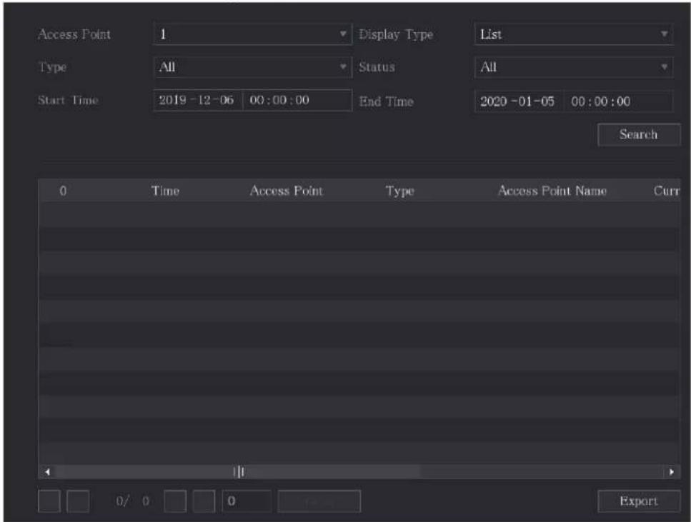
Step 2 Configure the parameters settings.
Table 5-42 IOT search parameters
| Parameter Description | |
| Access Point | Indicates the channel that the camera is connected to. |
| Display Type | In the Display Type list, select List or Diagram. |
| Type | Select the information type that you want to search. You can select Humidity or Temperature. |
| Status | Select the information state that you want to search.This option is available when you select List in the Display Type list. |
| Start Time | Enter the start time and end time for the information that you want to search. |
| End Time |
Step 3 Click Search.
The system starts search according to your parameters settings. After searching is finished, the result displays.

Click Goto to switch result pages.
Figure 5-267 List
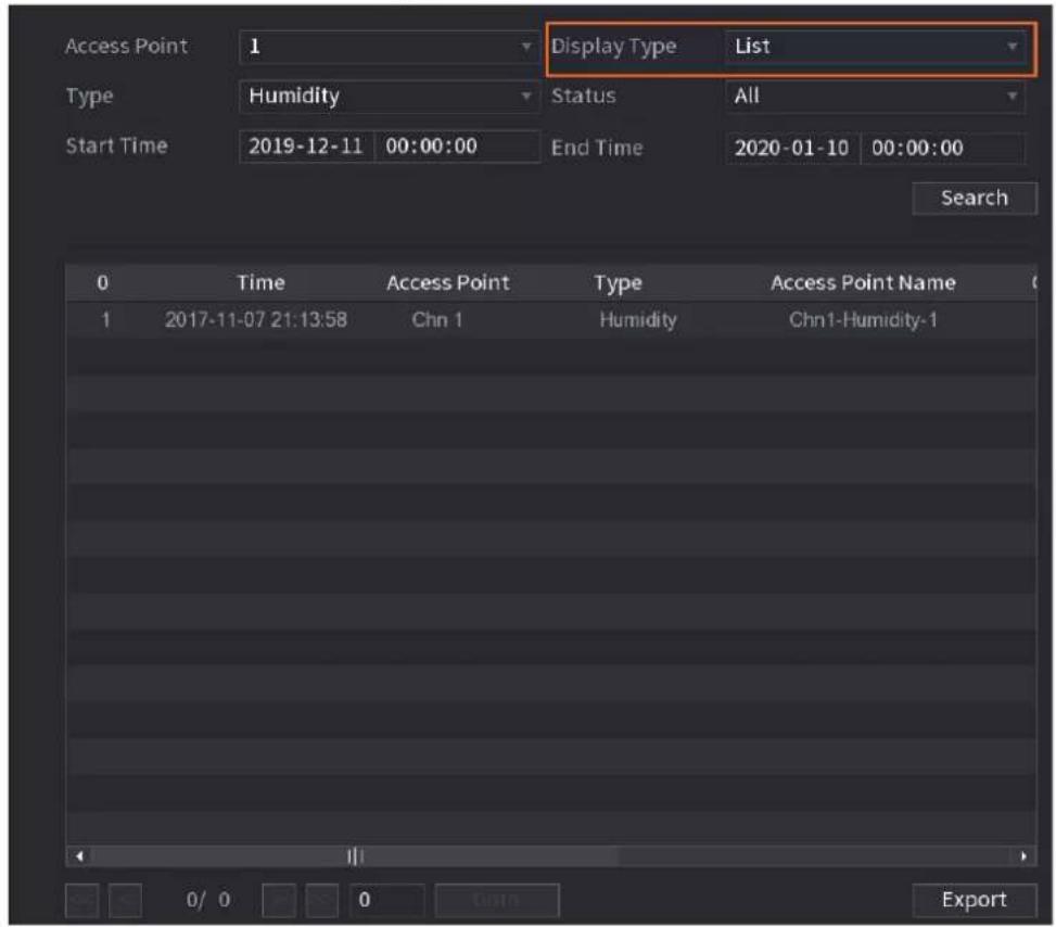
Figure 5-268 Diagram
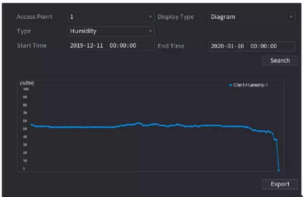
line
| Time | Humidity (%) | | ---------- | ------------ | | 2019-12-11 | 50 | | 00:00:00 | 50 | | End Time | 50 | | 2020-01-10 | 50 | | Export | 0 |Step 4 Click Export. The system starts exporting the data.
Step 5 Click OK.
You can find the exported data on your USB device.
5.12.3 Configuring Wireless Siren
You can connect the wireless siren to the Device, when there is an alarm event activated on the Device, the wireless siren generates alarms.
Step 1 Select Main Menu > IoT > Management > Wireless Siren.
Figure 5-269 Wireless siren
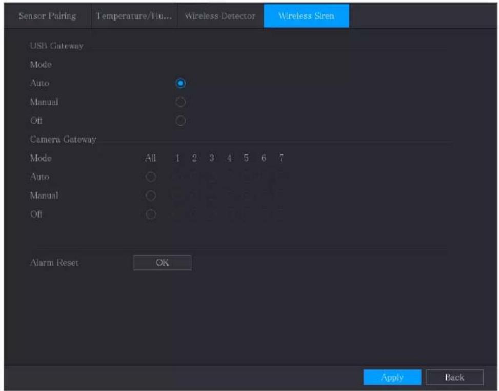
Step 2 Configure the settings for the wireless alarm output.
Table 5-43 Wireless alarm output parameters
| Parameter Description | |
| USB Gateway, Camera Gateway | ● Auto: Automatically activate alarm if the alarm output function for wireless siren is enabled for specific events.● Manual: Activate alarm immediately.● Off: Do not activate alarm. |
| Alarm Release | Click OK to clear all alarm output status of wireless siren. |
Step 3 Click Apply to save the settings.
5.13 Configuring POS Settings
You can connect the Device to the POS (Point of Sale) machine and receive the information from it. This function applies to the scenarios such as supermarket POS machine. After connection is established, the Device can access the POS information and display the overlaid text in the channel window.

Playing POS information in the local playback and viewing the POS information in the live view screen only support single-channel mode and four-channel mode. Displaying monitoring screen and playing back in the web support multi-channel mode.
5.13.1 Searching the Transaction Records

The system supports fuzzy search.
Step 1 Select Main Menu > POS > POS Search.
Figure 5-270 POS search
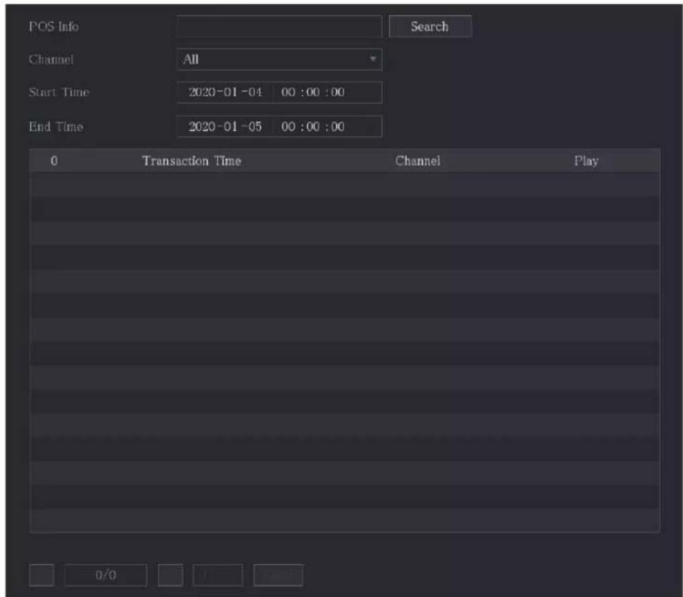
Step 2 In the POS Search box, enter the information such as transaction number on your receipt, amount, or product name.
Step 3 In the Start Time box and End Time box, enter the time period that you want to search the POS transaction information.
Step 4 Click Search.
The searched transaction results display in the table.
5.13.2 Configuring POS Settings
Step 1 Select Main Menu > POS > POS Setting.
Figure 5-271 POS setting
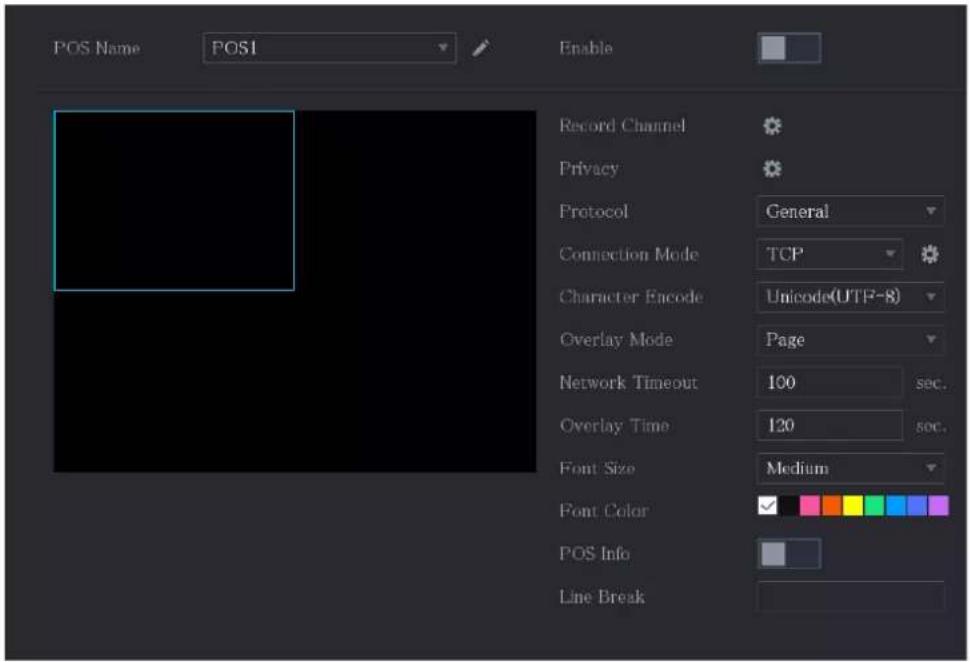
Step 2 Configure the settings for the POS parameters.
Table 5-44 POS parameters
| Parameter Description | |
| POS Name | In the POS Name list, select the POS machine that you want toconfigure settings for. Click  to modify the POS name. to modify the POS name. The POS name supports 21 Chinese characters or 63 English characters. The POS name supports 21 Chinese characters or 63 English characters. |
| Enable Enable the POS function. | |
| Record Channel | Select the channel(s) that you want to record. The selected channel(s) starts recording after an alarm occurs. The recording for POS alarms and auto recording function must be enabled. For details, see "5.1.4.9 Configuring Recorded Video Storage Schedule" and "5.9.1 Enabling Record Control". The recording for POS alarms and auto recording function must be enabled. For details, see "5.1.4.9 Configuring Recorded Video Storage Schedule" and "5.9.1 Enabling Record Control". |
| Privacy | Enter the privacy content. |
| Protocol | Select POS by default. Different machine corresponds to different protocol. |
| Connection Mode | In the Connect Type list, select the connection protocol type. Click the IP Address page is displayed.In the Source IP box, enter the IP address (the machine that is connected to the Device) that sends messages. the IP Address page is displayed.In the Source IP box, enter the IP address (the machine that is connected to the Device) that sends messages. |
| Character Encode | Select a character encoding mode. |
| Overlay Mode | In the Overlay Mode list, Select Page or ROLL.Page means to turn a page when there are 16 lines of overlay information.ROLL means to roll up the page when there are 16 lines of overlay information. The first line disappears each time.When local preview mode is 4-split, overlay information is substituted when there are 8 lines. |
| Network Timeout | When the network is not working correctly and cannot be recovered after the entered timeout limit, the POS information will not display normally. After the network is recovered, the latest POS information will be displayed. |
| Overlay Time | Enter the time that how long you want to keep the POS information displaying. For example, enter 5, the POS information disappear from the screen after 5 seconds. |
| Font Size | In the Font Size list, select Small, Medium, or Large as the text size of POS information |
| Font Color | In the color bar, click to select the color for the text size of POS information. |
| POS Info | Enable the POS Info function, the POS information displays in the live view screen. |
| Line Break | It does not need to configure. The system goes to a new line 1s after no data is received.If you enter a line delimiter, the system goes to a new line when overlay information identifies the line delimiter (hexadecimal).For example, if line delimiter is F and overlay information is 123F6789, the local preview and web overlay information is displayed as:1236789 |
Step 3 Click Apply to complete the settings.
5.14 Configuring Backup Settings
5.14.1 Finding USB Device
When you inset a USB storage device into the USB port of the Device, the Device detects the USB storage device and pops up Find USB device page, which provides you a shortcut to perform backup and upgrading operations.
For details, see "5.14.2 Backing up Files", "5.21.2 Viewing Log Information", "5.20.4 Exporting and Importing System Settings", and "5.20.6 Updating the Device".
Figure 5-272 Backup device
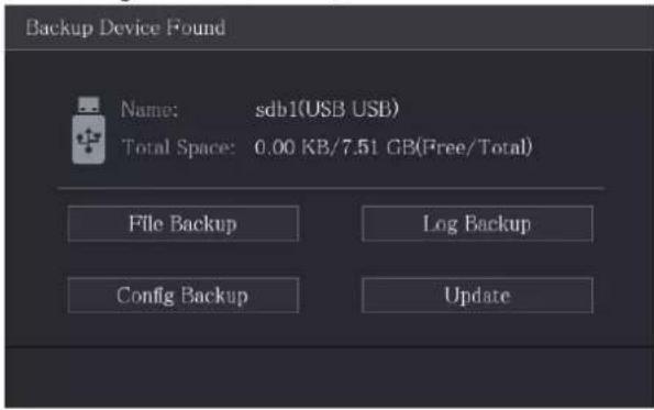
5.14.2 Backing up Files
You can back up the recorded videos and snapshots.
Step 1 Select Main Menu > Backup.
Figure 5-273 Backup
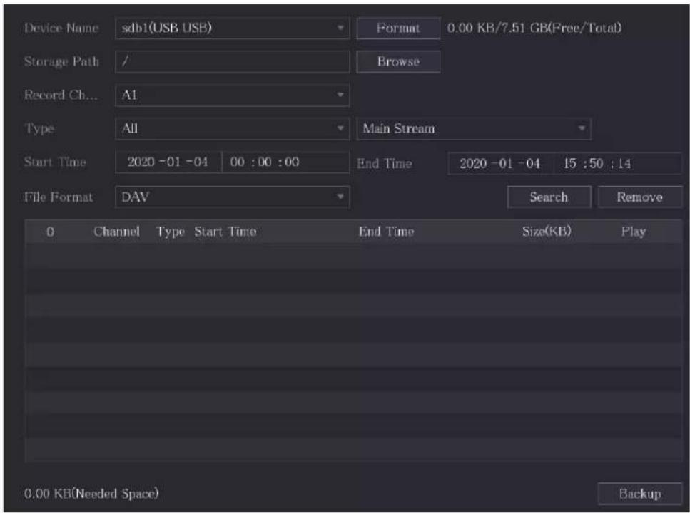
Step 2 Configure the settings for the backup parameters.
Table 5-45 Backup parameters
| Parameter Description | |
| Device Name | In the Device Name list, select the device that you want to back up the files to. |
| Format | Click Format, the Format page is displayed.If the capacity of external storage device is less than 2 TB, you can select FAT32 or NTFS to format it.If the capacity of external storage device is equal to or more than 2 TB, you can only select NTFS to format it. |
| Path | ClickBrowse, theBrowsepage is displayed. Select the route where you want to search for the files. |
| Record Channel | In theRecord Channellist, select the channel where you want to search for the files. |
| Type | In theTypelist, select the file type that you want to search. |
| Start Time | Enter the start time and end time for the files that you want to search. |
| End Time | |
| File Format | In theFile Formatlist, select the file format asDAVorMP4that you want to search. |
Step 3 Click Search to search the files that meet the configured settings.
The searched results will display in the table.
Step 4 Select the files that you want to back up.
Step 5 Click Backup to back up the selected files to the configured path.

Click Remove to remove all the searched results.
The system will display a backup progress bar. A dialog box will be prompted When backup is completed.
Figure 5-274 Browse
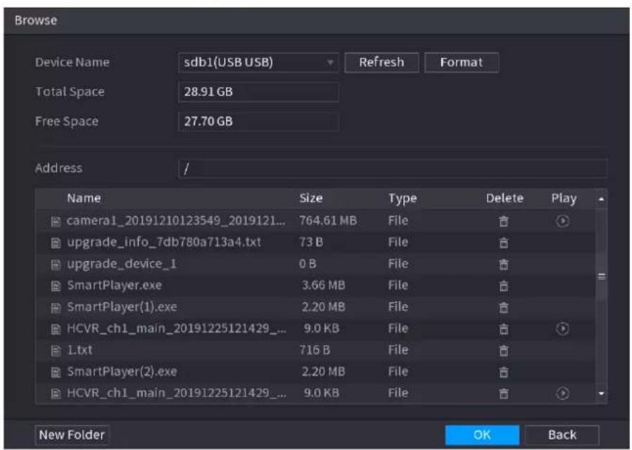
Step 6 Click OK.
5.15 Network Management
5.15.1 Configuring Network Settings
You can ensure the network interworking between the Device and other devices through configuring the network settings.
5.15.1.1 Configuring TCP/IP Settings
You can configure the settings for the Device such as IP address, DNS according to the networking plan.
Select Main Menu > NETWORK > TCP/IP, the TCP/IP page is displayed.
For details about parameter settings, see "5.1.4.4 Configuring Network Settings".
Figure 5-275 TCP/IP
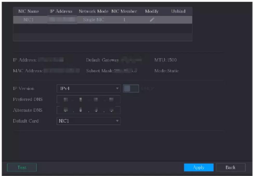
5.15.1.2 Configuring Port Settings
You can configure the maximum connection accessing the Device from Client such as WEB, Platform, and Mobile Phone and configure each port settings.
Step 1 Select Main Menu > NETWORK > Port.
Figure 5-276 Port
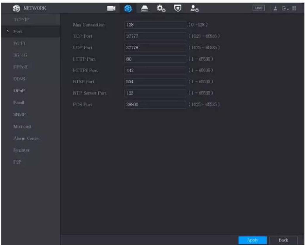
Step 2 Configure the settings for the connection parameters.
Table 5-46 Connection parameters
| Parameter Description | |
| Max Connection | The allowable maximum clients accessing the Device at the same time, such as WEB, Platform, and Mobile Phone.Select a value between 1 and 128. The default value setting is 128. |
| TCP Port | The default value setting is 37777. You can enter the value according to your actual situation. |
| UDP Port | The default value setting is 37778. You can enter the value according to your actual situation. |
| HTTP Port | The default value setting is 80. You can enter the value according to your actual situation.If you enter other value, for example, 70, and then you should enter 70 after the IP address when logging in the Device by browser. |
| RTSP Port | The default value setting is 554. You can enter the value according to your actual situation. |
| POS Port | Data transmission. The value range is from 1 through 65535. The default value is 38800. |
| NTP Server Port | The default value setting is 123. You can enter the value according to your actual situation. |
| HTTPS Port | HTTPS communication port. The default value setting is 443. You can enter the value according to your actual situation. |
Step 3 Click Apply to complete the settings.
5.15.1.3 Configuring Wi-Fi Connection Settings
You can make wireless connection between the Device and the other devices in the same network through Wi-Fi settings, facilitating the devices connection and mobility.

Only the Device with Wi-Fi module supports this function.
Step 1 Select Main Menu > NETWORK > Wi-Fi.
Figure 5-277 Wi-Fi
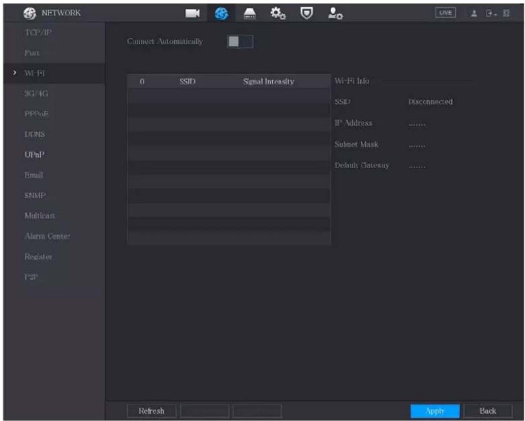
Step 2 Configure the settings for the Wi-Fi connection parameters.
Table 5-47 Wi-Fi connection parameters
| Parameter Description | |
| Connect Automatically | Enable Connect Automatically.After the Device is restarted, it will automatically connect to the nearest hotspot that had been connected successfully. |
| Refresh | Refresh the hotspot list. The self-adaption function such as adding password is supported if such setting was once configured. |
| Connect | In the hotpots list, select a hotspot, and then click Connect.To reconnect the same hotspot, disconnect first and then reconnect.To connect to other hotspot, disconnect from the current connected hotspot first, and then connect to the other hotspot. |
| Disconnect | To disconnect from a hotspot, click Disconnect. |
Step 3 Click Apply to complete the settings.
After the Device is connected to a Wi-Fi hotspot, in the Wi-Fi Info area, the current hotspot, IP address, subnet mask, and default gateway are displayed.
5.15.1.4 Configuring 3G/4G Settings
You can connect a wireless 3G/4G module to the USB port of the Device and then access the Device with the IP address provided by the module.

This function is available on select models.
Step 1 Connect the wireless 3G/4G module to the USB port of the Device.
Step 2 Select Main Menu > NETWORK > 3G/4G.
Figure 5-278 3G/4G
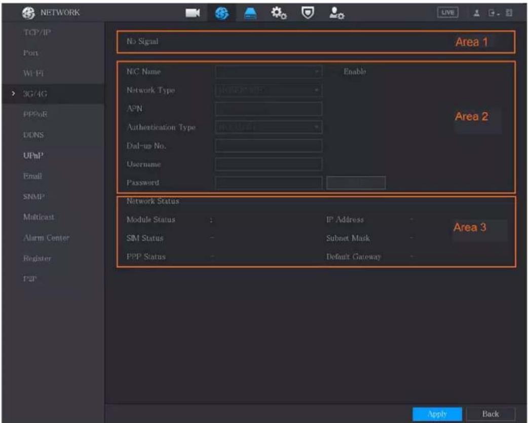
The 3G/4G page consists of three areas:
• Area 1: Displays the signal strength.
• Area 2: Displays the module configurations.
• Area 3: Displays the connection state.

The information of Area 2 will display after the 3G/4G module is connected; while the information of Area 1 and Area 3 will display only after the 3G/4G function is enabled.
Step 3 The Device starts identifying the wireless module and displays the recognized information for the parameters in Area 2.
Table 5-48 Recognized information
| Parameter Description | |
| NIC Name | Displays the name of Ethernet card. |
| Network Type | Displays the network type. Different type represents different supplier. |
| APN | Displays the default APN number. |
| Dial-up No. | Displays the default dial No. |
| Authentication Type | Authentication mode. You can select PAP, CHAP, or NO_AUTH. |
| Username, Password | Enter the username and password for authentication. |
Step 4 Select the Enable checkbox.
Step 5 Click Dial to start connecting.
After the connection is established, the result is displayed in the Wireless Network area.
Figure 5-279 Wireless network
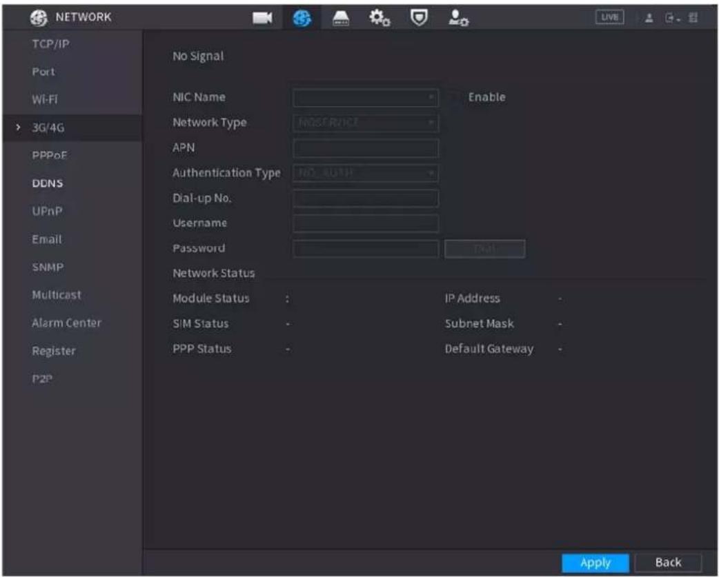
Step 6 Click Apply to complete the settings.
5.15.1.5 Configuring PPPoE Settings
PPPoE is another way for the Device to access the network. You can establish network connection by configuring PPPoE settings to give the Device a dynamic IP address in the WAN. To use this function, firstly you need to obtain the username and password from the Internet Service Provider.
Step 1 Select Main Menu > NETWORK > PPPoE.
Figure 5-280 PPPoE
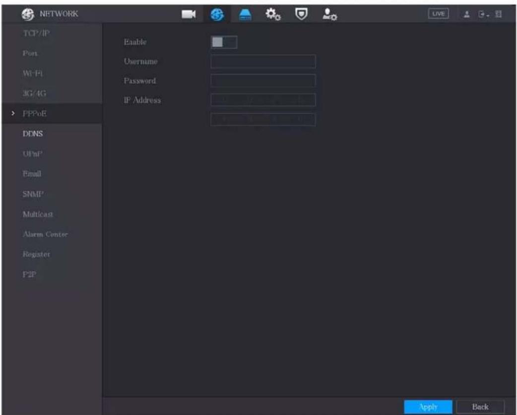
Step 2 Enable the PPPoE function.
Step 3 In the Username box and Password box, enter the username and password accordingly provided by the Internet Service Provider.
Step 4 Click Apply to complete the settings.
The system pops up a message to indicate the successfully saved. The IP address appears on the PPPoE page. You can use this IP address to access the Device.

When the PPPoE function is enabled, the IP address on the TCP/IP page cannot be modified.
5.15.1.6 Configuring DDNS Settings
When the IP address of the Device changes frequently, the DDNS function can dynamically refresh the correspondence between the domain on DNS and the IP address, ensuring you access the Device by using the domain.
Preparation
Confirm if the Device supports the DDNS Type and log in the website provided by the DDNS service provider to register the information such as domain from PC located in the WAN.

After you have registered and logged in the DDNS website successfully, you can view the information of all the connected devices under this username.
Procedure
Step 1 Select Main Menu > NETWORK > DDNS.
Figure 5-281 DDNS
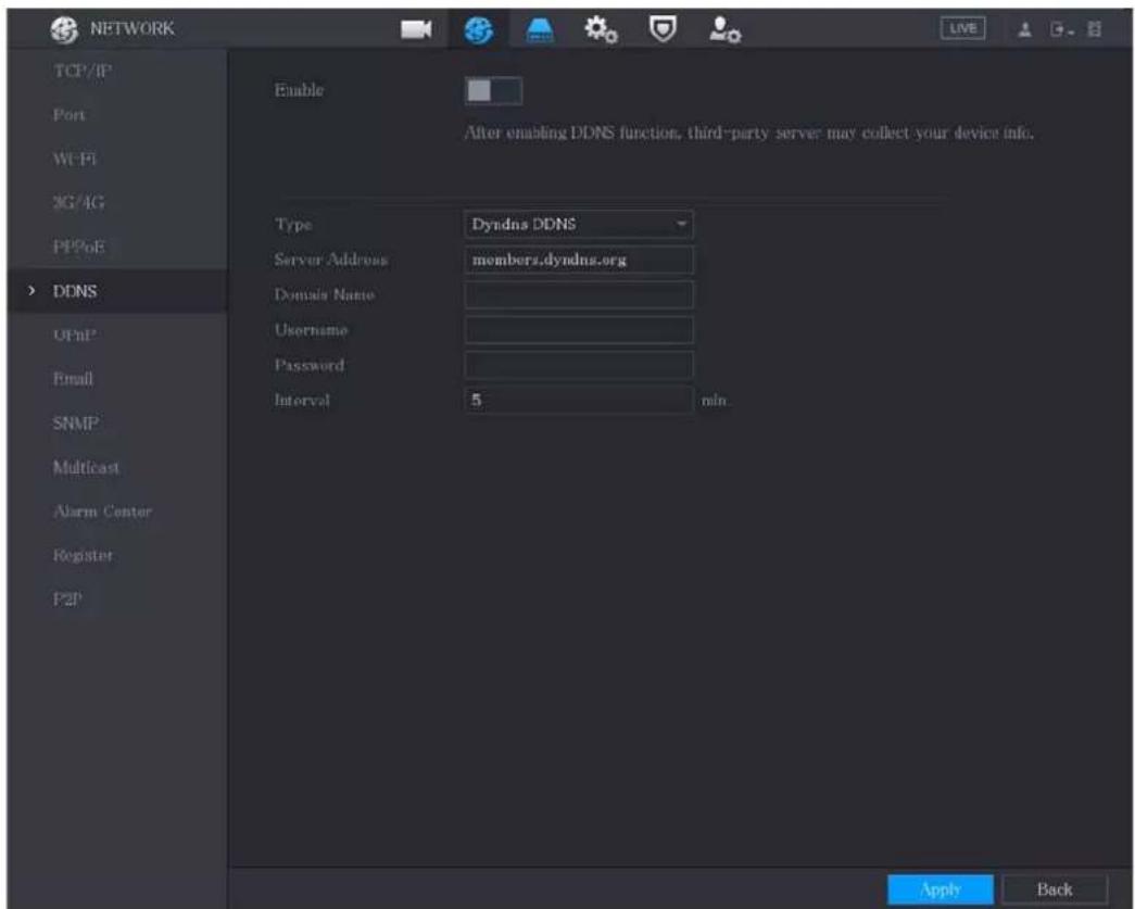
Step 2 Configure the settings for the DDNS parameters.
Table 5-49 DDNS parameters
| Parameter Description | |
| Enable | Enable the DDNS function. |
| After enabling DDNS function, the third-party might collect your Device information. | |
| Type | Type and address of DDNS service provider. |
| Server Address | Type: Dyndns DDNS; address: members.dyndns.orgType: NO-IP DDNS; address: dynupdate.no-ip.comType: CN99 DDNS; address: members.3322.org |
| Domain Name | The domain name for registering on the website of DDNS service provider. |
| Username | Enter the username and password obtained from DDNS service provider. |
| Password | You need to register (including username and password) on the website of DDNS service provider. |
| Interval | Enter the amount of time that you want to update the DDNS. |
Step 3 Click Apply to complete the settings.
Enter the domain name in the browser on your PC, and then press Enter.
If the web page of the Device is displayed, the configuration is successful. If not, the configuration is failed.
5.15.1.7 Configuring EMAIL Settings
You can configure the email settings to enable the system to send the email as a notification when there is an alarm event occurs.
Step 1 Select Main Menu > NETWORK > Email.
Figure 5-282 Email
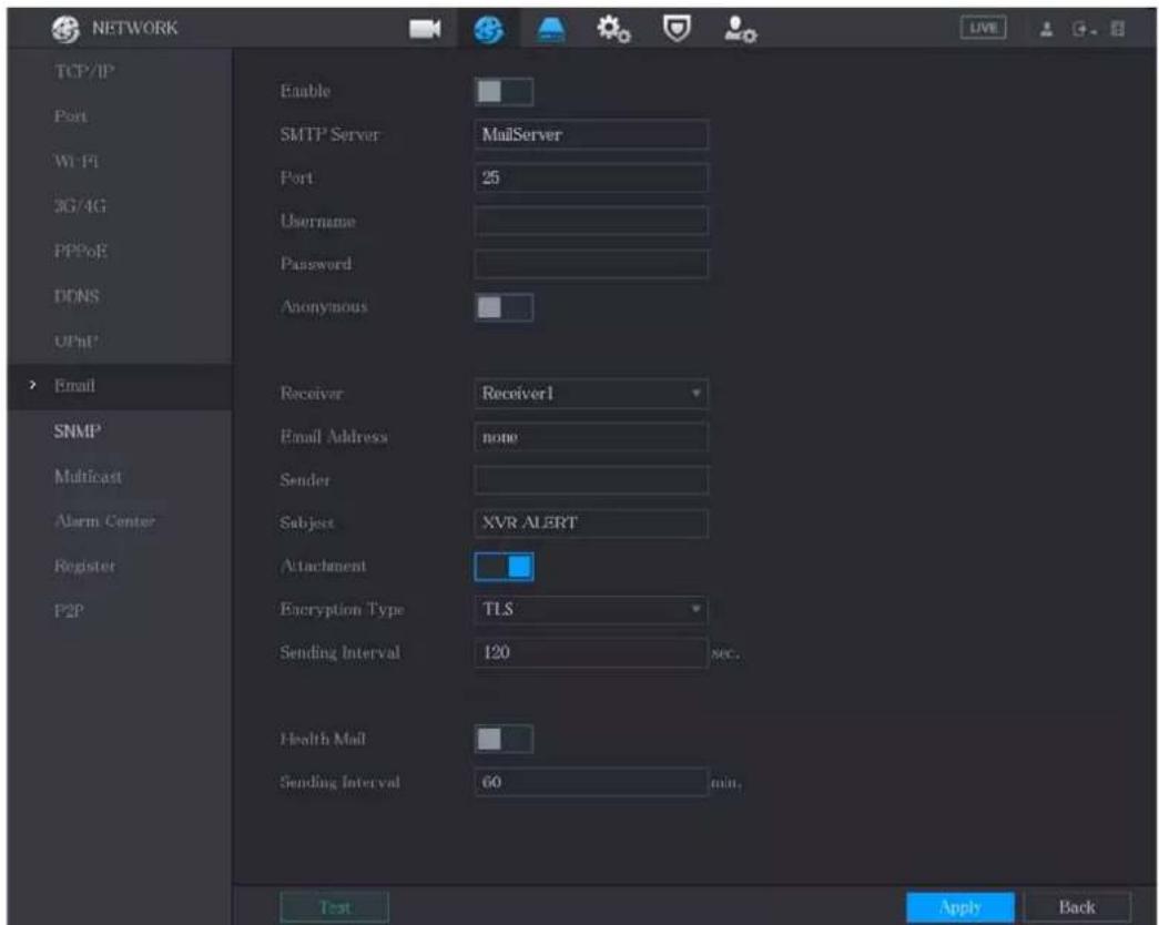
Step 2 Configure the settings for the email parameters.
Table 5-50 Email parameters
| Parameter Description | |
| Enable | Enable the email function.There might be risk of sending data to specified email address after it is enabled. |
| SMTP Server | Enter the address of SMTP server of sender's email account. |
| Port | Enter the port value of SMTP server. The default value setting is 25. You can enter the value according to your actual situation. |
| Username | Enter the username and password of sender's email account. |
| Password | |
| Anonymous | If enable the anonymity function, you can login as anonymity. |
| Receiver | In the Receiver list, select the number of receiver that you want to receive the notification. The Device supports up to three mail receivers. |
| Email Address | Enter the email address of mail receiver(s). |
| Sender | Enter the sender's email address. It supports maximum three senders separated by comma. |
| Subject | Enter the email subject.Supports Chinese, English and numerals. It supports maximum 64 characters. |
| Attachment | Enable the attachment function. When there is an alarm event, the system can attach snapshots as an attachment to the email. |
| Encryption Type | Select the encryption type: NONE, SSL, or TLS.For SMTP server, the default encryption type is TLS. |
| Sending Interval (sec.) | This is the interval that the system sends an email for the same type of alarm event, which means, the system does not send an email upon any alarm event.This setting helps to avoid the large amount of emails caused by frequent alarm events.The value ranges from 0 to 3600. 0 means that there is no interval. |
| Health Mail | Enable the health test function. The system can send a test email to check the connection. |
| Sending Interval (Min.) | This is the interval that the system sends a health test email.The value ranges from 30 to 1440. 0 means that there is no interval. |
| Test | Click Test to test the email sending function. If the configuration is correct, the receiver's email account will receive the email.Before testing, click Apply to save the settings. |
Step 3 Click Apply to complete the settings.
5.15.1.8 Configuring UPnP Settings
You can map the relationship between the LAN and the WAN to access the Device on the LAN through the IP address on the WAN.
Preparation
- Log in to the router to set the WAN port to enable the IP address to connect into the WAN.
- Enable the UPnP function at the router.
- Connect the Device with the LAN port on the router to connect into the LAN.
- Select Main Menu > NETWORK > TCP/IP, configure the IP address into the router IP address range, or enable the DHCP function to obtain an IP address automatically.
Procedure
Step 1 Select Main Menu > NETWORK > UPnP.
Figure 5-283 UPnP
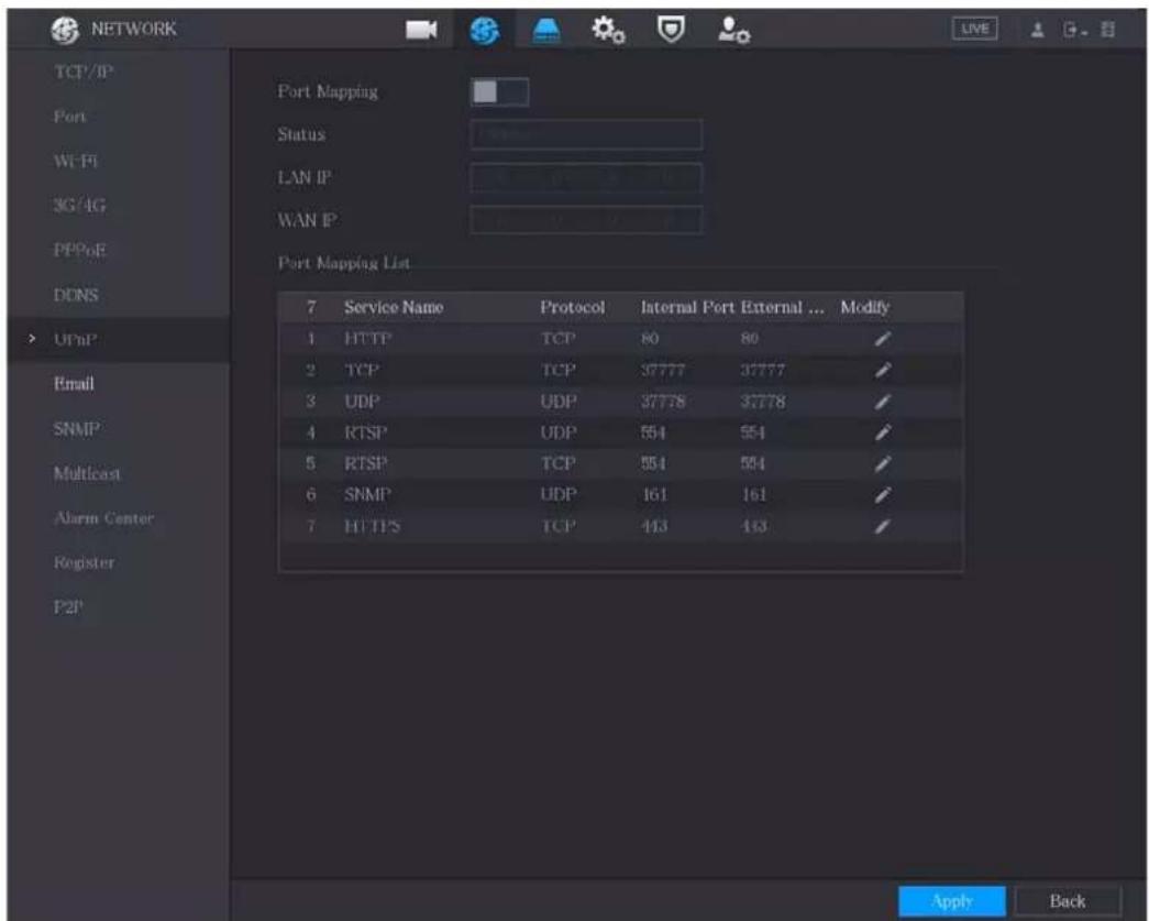
Step 2 Configure the settings for the UPnP parameters.
Table 5-51 UPnP parameters
| Parameter Description | |
| Port Mapping | Enable the UPnP function. After it is enabled, the intranet services and ports shall be mapped to extranet, proceed with caution. After it is enabled, the intranet services and ports shall be mapped to extranet, proceed with caution. |
| Status | Indicates the status of UPnP function.● Offline: Failed.● Online: Succeeded. |
| LAN IP | Enter IP address of router on the LAN. After mapping succeeded, the system obtains IP address automatically without performing any configurations. After mapping succeeded, the system obtains IP address automatically without performing any configurations. |
| WAN IP | Enter IP address of router on the WAN. After mapping succeeded, the system obtains IP address automatically without performing any configurations. After mapping succeeded, the system obtains IP address automatically without performing any configurations. |
After it is enabled, the intranet services and ports shall be mapped to extranet, proceed with caution.
- Offline: Failed.
- Online: Succeeded.
After mapping succeeded, the system obtains IP address automatically without performing any configurations.
| Parameter Description | |
| Port Mapping List | The settings in PAT table correspond to the UPnP PAT table on the router.● Service Name: Name of network server.● Protocol: Type of protocol.● Int. Port: Internal port that is mapped on the Device.● Ext. Port: External port that is mapped on the router.[IMAGE]● To avoid the conflict, when setting the external port, try to use the ports from 1024 through 5000 and avoid popular ports from 1 through 255 and system ports from 256 through 1023.● When there are several devices in the LAN, reasonably arrange the ports mapping to avoid mapping to the same external port.● When establishing a mapping relationship, ensure the mapping ports are not occupied or limited.● The internal and external ports of TCP and UDP must be the same and cannot be modified.● Click [icon] to modify the external port. |
Step 3 Click Apply to complete the settings.
In the browser, enter http://WAN IP: External IP port. You can visit the LAN Device.
5.15.1.9 Configuring SNMP Settings

This function is available on select models.
You can connect the Device with some software such as MIB Builder and MG-SOFT MIB Browser to manage and control the Device from the software.
Preparation
- Install the software that can manage and control the SNMP, such as MIB Builder and MG-SOFT MIB Browser
- Obtain the MIB files that correspond to the current version from the technical support.
Procedure
Step 1 Select Main Menu > NETWORK > SNMP.
Figure 5-284 SNMP
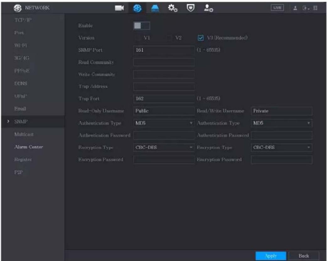
Step 2 Configure the settings for the SNMP parameters.
Table 5-52 SNMP parameters
| Parameter Description | |
| Enable | Enable the SNMP function. |
| Version | Select the checkbox of SNMP version(s) that you are using. The default version is V3. There is a risk of select V1 or V2. The default version is V3. There is a risk of select V1 or V2. |
| SNMP Port | Indicates the monitoring port on the agent program. |
| Read Community | Indicates the read/write strings supported by the agent program. |
| Write Community | |
| Trap Address | Indicates the destination address for the agent program to send the Trap information. |
| Trap Port | Indicates the destination port for the agent program to send the Trap information. |
| Read-Only Username | Enter the username that is allowed to access the Device and has the "Read Only" permission. |
| Read/Write Username | Enter the username that is allowed to access the Device and has the "Read and Write" permission. |
| Authentication Type | Includes MD5 and SHA. The system recognizes automatically. |
| Authentication Password | Enter the password for authentication type and encryption type. The password should be no less than eight characters. |
| Encryption Password | |
| Encryption Type | In the Encryption Type list, select an encryption type. The default setting is CBC-DES. |
Step 3 Compile the two MIB files by MIB Builder.
Step 4 Run MG-SOFT MIB Browser to load in the module from compilation.
Step 5 On the MG-SOFT MIB Browser, enter the Device IP that you want to manage, and then select the version number to query.
Step 6 On the MG-SOFT MIB Browser, unfold the tree-structured directory to obtain the configurations of the Device, such as the channels quantity and software version.
5.15.1.10 Configuring Multicast Settings
When you access the Device from the network to view the video, if the access is exceeded, the video will not display. You can use the multicast function to group the IP to solve the problem.
Step 1 Select Main Menu > NETWORK > Multicast.
Figure 5-285 Multicast
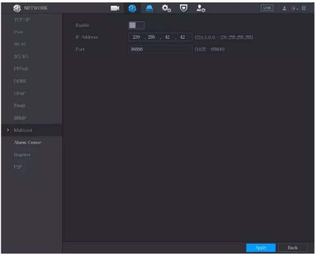
Step 2 Configure the settings for the multicast parameters.
Table 5-53 Multicast parameters
| Parameter Description | |
| Enable | Enable the multicast function. |
| IP Address | Enter the IP address that you want to use as the multicast IP.The IP address ranges from 224.0.0.0 through 239.255.255.255. |
| Port | Enter the port for the multicast. The port ranges from 1025 through 65000. |
Step 3 Click Apply to complete the settings.
You can use the multicast IP address to log in to the web.
On the web login dialog box, in the Type list, select MULTICAST. The web will automatically obtain the multicast IP address and join. Then you can view the video through multicast function.
Figure 5-286 Login
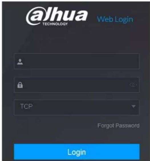
5.15.1.11 Configuring Register Settings
You can register the Device into the specified proxy server which acts as the transit to make it easier for the client software to access the Device.
Step 1 Select Main Menu > NETWORK > Register.
Figure 5-287 Register
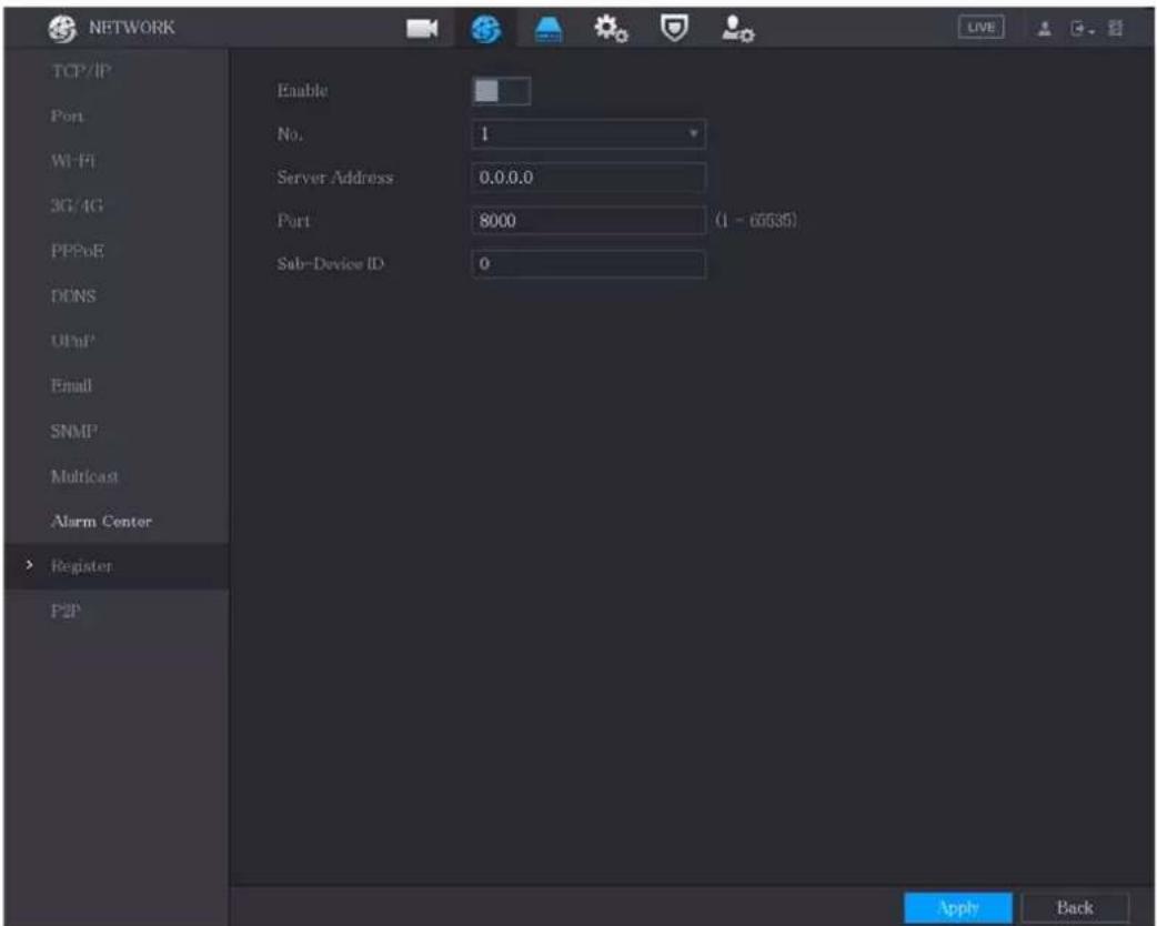
Step 2 Configure the settings for the register parameters.
Table 5-54 Register parameters
| Parameter Description | |
| Enable | Enable the register function. |
| No. The default value is 1. | |
| Server IP Address | Enter the server IP address or the server domain that you want to register to. |
| Port | Enter the port of the server. |
| Sub Service ID | This ID is allocated by the server and used for the Device. |
Step 3 Click Apply to complete the settings.
5.15.1.12 Configuring Alarm Center Settings
You can configure the alarm center server to receive the uploaded alarm information. To use this function, the Report Alarm checkbox must be selected. For details about alarm event settings, see "5.10 Alarm Events Settings".
Step 1 Select Main Menu > NETWORK > Alarm Center.
Figure 5-288 Alarm center
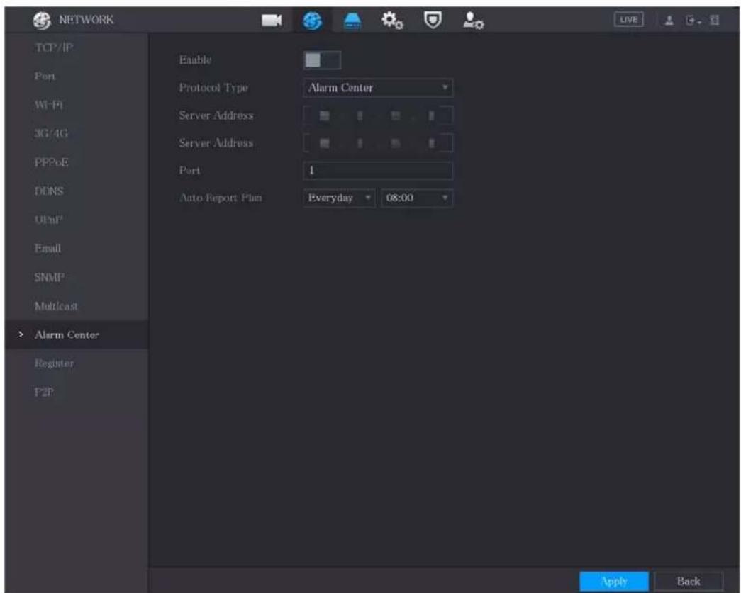
Step 2 Configure the settings for the alarm center parameters.
Table 5-55 Alarm center parameters
| Parameter Description | |
| Enable | Enable the alarm center function. |
| Protocol Type | In theProtocol Typelist, select protocol type. The default isALARM CENTER. |
| Server Address | The IP address and communication port of the PC installed with alarm client. |
| Port | |
| Auto Report Plan | In the Auto Report Plan list, select time cycle and specific time for uploading alarm. |
Step 3 Click Apply to complete the settings.
5.15.1.13 Configuring P2P Settings
You can manage the devices by using P2P technology to download the application and register the devices. For details, see "5.1.4.5 Configuring P2P Settings".
5.15.2 Configuring Network Testing Settings
5.15.2.1 Testing the Network
You can test the network connection status between the Device and other devices.
Step 1 Select Main Menu > MAINTAIN > Network > Test.
Figure 5-289 Network test
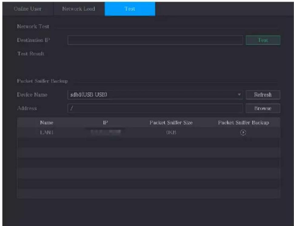
Step 2 In the Destination IP box, enter the IP address.
Step 3 Click Test.
After testing is completed, the test result is displayed. You can check the evaluation for average delay, packet loss, and network status.
Figure 5-290 Test result
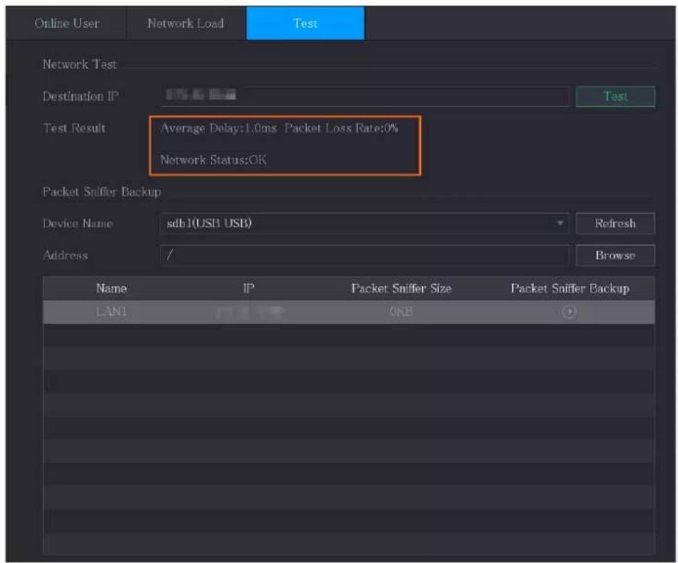
5.15.2.2 Capturing Packet and Backing up
Packet capture means the operations such as capturing, resending, and editing data that are sent and received during network transmission. When there is network abnormality, you can perform packet capturing and back up into the USB storage device. This date can be provided to the technical support for analyzing the network condition.
Step 1 Select Main Menu > MAINTAIN > Network > Test.
Figure 5-291 Test
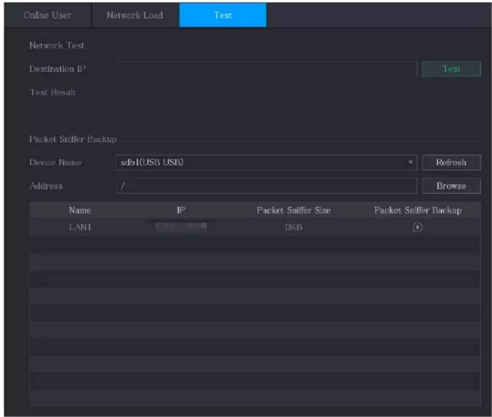
Step 2 Connect a USB storage device to the Device.
Step 3 Click Refresh.
The Device starts detecting the USB storage device and displays its name in the Device Name box.
Step 4 Select the route of the data that you want to capture and back up.
1) In the Packet Sniffer Backup area, click Browse.
Figure 5-292 Browse
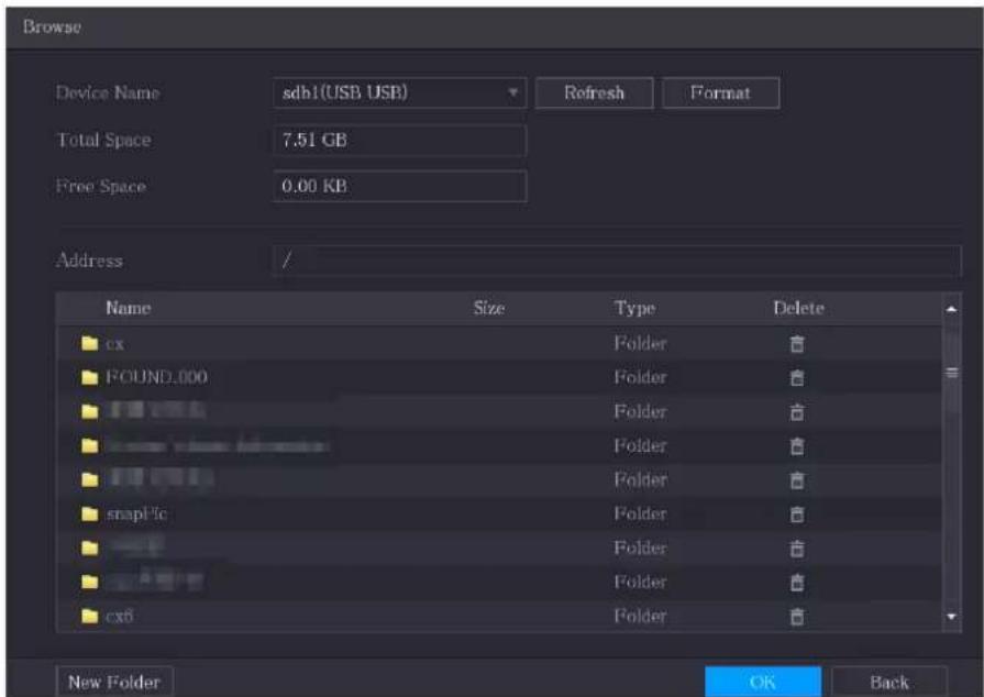
2) Select the route.

- If several USB storage devices are connected to the Device, you can select from the Device Name list.
- Click Refresh to total space, free space and the file list in the selected USB storage device.
- Click New Folder to create a new folder in the USB storage device.

3) Click OK to save the route selection settings.
Step 5
Click

to start packet capturing and backing up.

- Only the data packet of one LAN can be captured at one time.
- After capturing starts, you can exit the Test page to perform other operations such as web login and monitoring.
Step 6

to stop capturing.
The backup data is saved in the selected route under the naming style "LAN name-time.pcap". You can open it by using Wireshark software.
Figure 5-293 Backup data
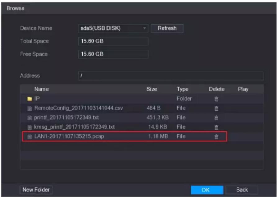
5.16 Configuring Account Settings
You can add, modify and delete user accounts, groups, and ONVIF users, and set security questions for admin account.

- The username supports 31 characters and group name supports 15 characters. The username can be consisted of letter, number, " _ ", "@", "",
- You can set maximum 64 users and 20 groups. The group name by "User" and "Admin" cannot be deleted. You can set other groups and define the relevant permissions. However, the admin account cannot be set randomly.
- You can manage the account by user and group and the name cannot be repeated. Every user must belong to a group, and one user only belongs to one group.
5.16.1 Configuring User Account
5.16.1.1 Adding a User Account
Step 1 Select Main Menu > ACCOUNT > User.
Figure 5-294 User
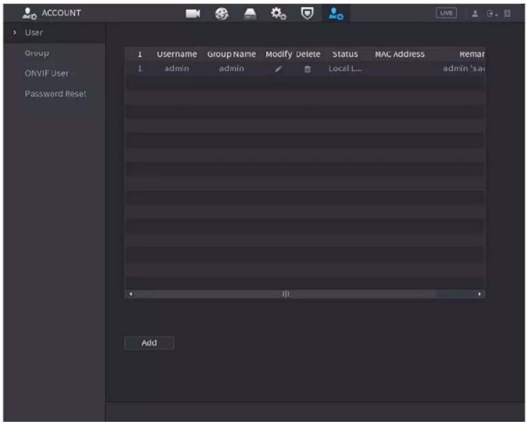
Step 2 Click Add.
Figure 5-295 Add user
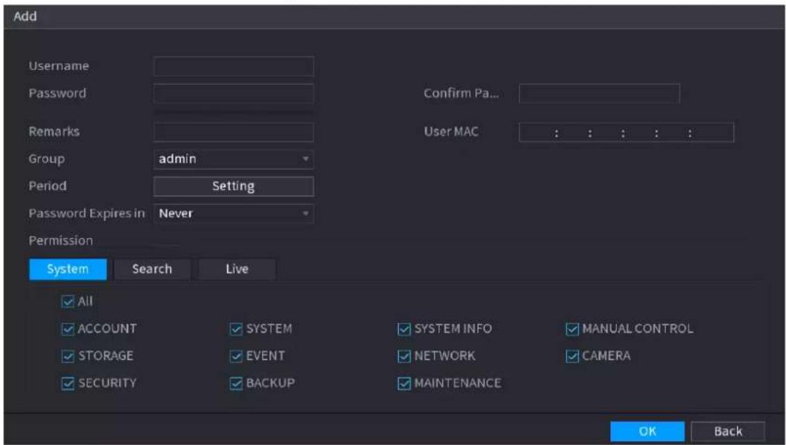
Step 3 Configure the settings for the parameters of adding a user account.
Table 5-56 Parameters of adding user
| Parameter Description | |
| Username | Enter a username and password for the account. |
| Password | |
| Confirm Password | Re-enter the password. |
| Remarks | Optional.Enter a description of the account. |
| User MAC Enter user MAC address | |
| Group | Select a group for the account. The user rights must be within the group permission. The user rights must be within the group permission. |
| Period | Click Setting to configure the parameters.Define a period during which the new account can log in to the device.The new account cannot log in to the device during the time beyond the set period. |
| Password Expires in | Set the password validity period. |
| Permission | In the Permission area, select the checkboxes in the System tab,Playback tab, and Monitor tab. To manage the user account easily, when defining the user account authority, it is recommended not to give the authority to the common user account higher that the advanced user account. To manage the user account easily, when defining the user account authority, it is recommended not to give the authority to the common user account higher that the advanced user account. |
Step 4 Click OK to complete the settings.
Setting Permitted Period
Step 1 Next to Period, click Setting.
Figure 5-296 Setting
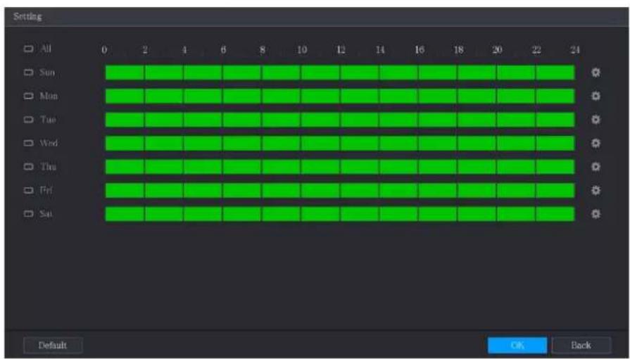
Step 2 Define the permitted period. By default, it is active all the time.
- Define the period by drawing.
☐ Define for a specified day of a week: On the timeline, click the half-hour blocks to select the active period.
Define for several days of a week: Click before each day, the icon switches to
On the timeline of any selected day, click the half-hour blocks to select the active periods, all the days with Will take the same settings.
Define for all days of a week: Click All, all the switches to On the timeline of any day, click the half-hour blocks to select the active periods, all the days will take the same settings.
- Define the period by editing. Take Sunday as an example.
1) Click
Figure 5-297 Period
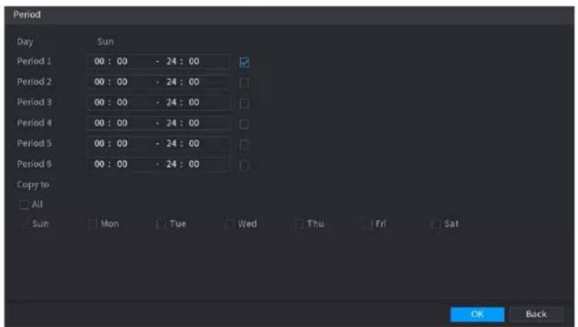
2) Enter the time frame for the period and select the checkbox to enable the settings.
◇ There are six periods for you to set for each day.
Under Copy, select All to apply the settings to all the days of a week, or select specific day(s) that you want to apply the settings to.
3) Click OK to save the settings.
Step 3 Click OK.
5.16.1.2 Modifying a User Account
Step 1 Select Main Menu > ACCOUNT > User.
Figure 5-298 User
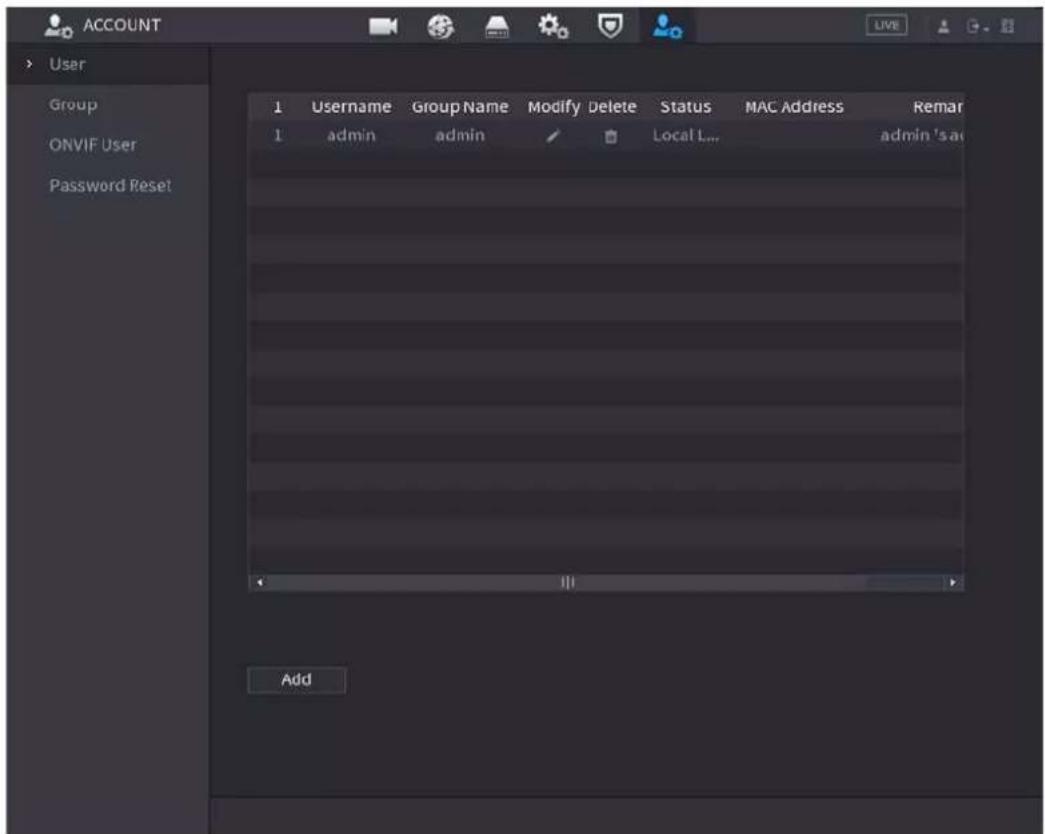
Step 2
Click

for the user account that you want to modify.
Figure 5-299 Modify
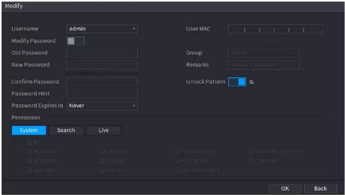
Step 3 Change the settings for password, username, user group, user MAC, memo, password validity period and authority.

The new password can be set from 8 digits through 32 digits and contains at least two types from number, letter and special characters (excluding "", "", ";", ";" and "&").
For the admin account, you enable/disable the unlock pattern and modify password hint.
- To use the unlock pattern, enable Unlock Pattern, click 🔥, draw a pattern in the Unlock Pattern page, and then click Save to save the setting.
- Enter password hint text in Password Hint box.
Step 4 Click OK to complete the settings.
5.16.1.3 Deleting a User Account
Step 1 Select Main Menu > ACCOUNT > User.
Figure 5-300 User
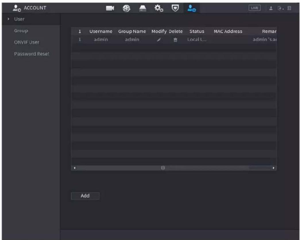
Step 2
Click

for the user account that you want to delete.
Step 3
Click OK to delete a user account.
5.16.2 Configuring Group Account
5.16.2.1 Adding a Group
Step 1 Select Main Menu > ACCOUNT > Group.
Figure 5-301 Group
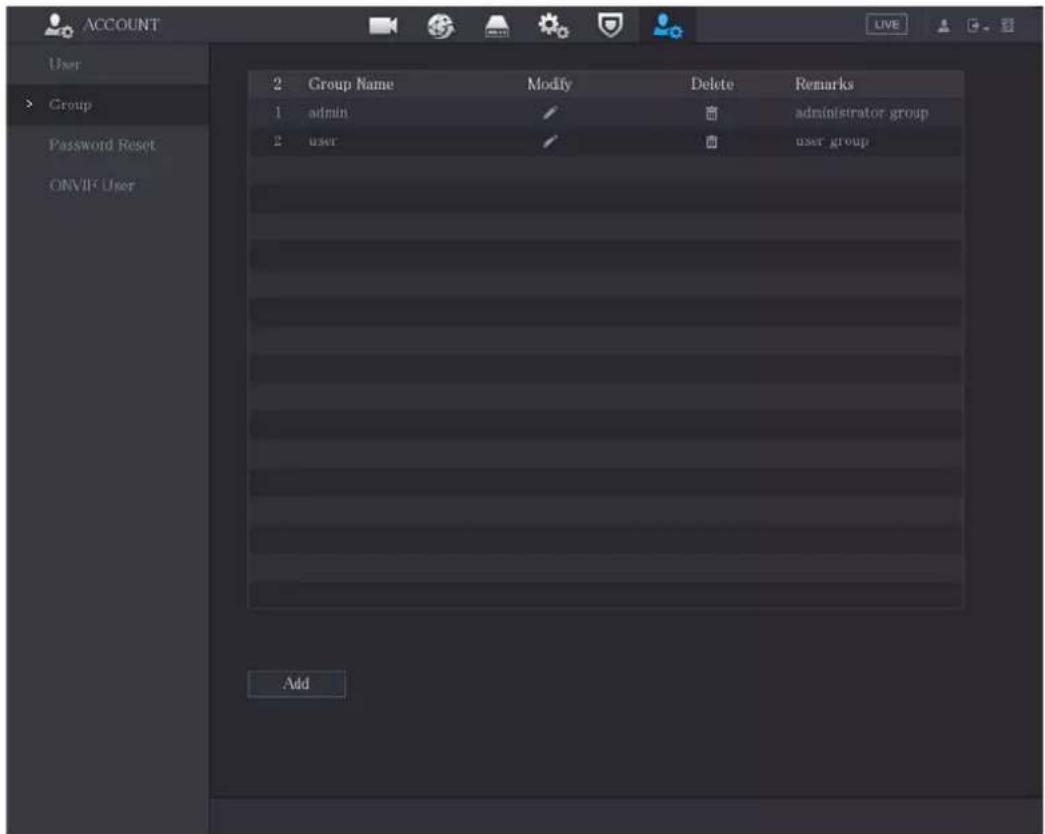
Step 2 Click Add.
Figure 5-302 Add group
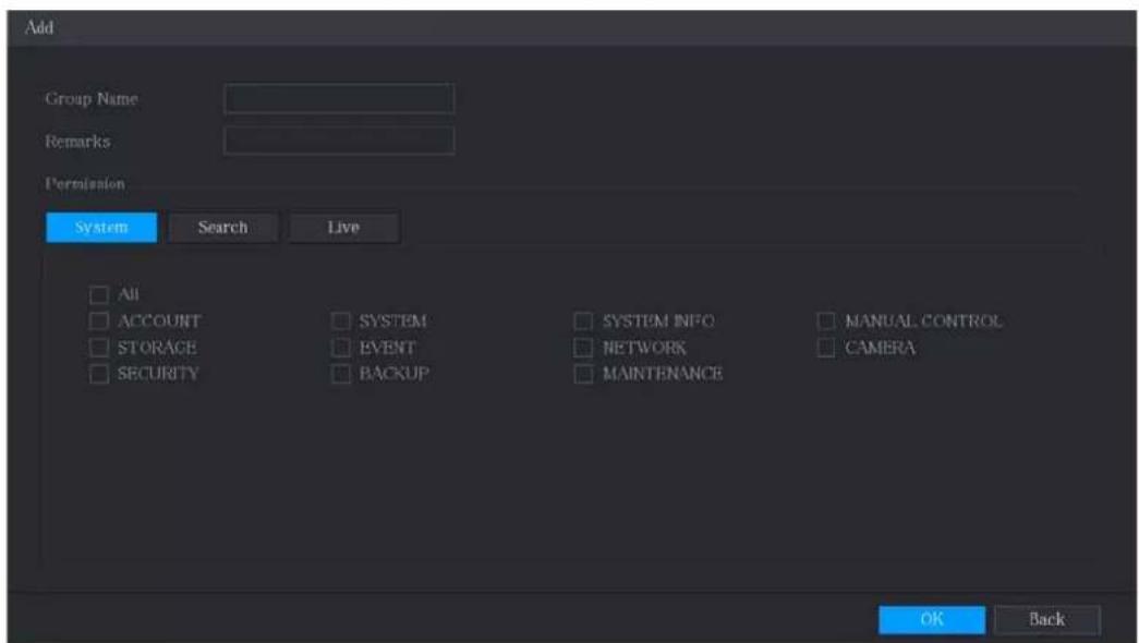
Step 3 Configure the settings for the parameters of adding a group.
Table 5-57 Parameters of adding a group
| Parameter Description | |
| Group Name | Enter a name for the group. |
| Remarks | Optional.Enter a description of the account. |
| Permission | In the Permission area, select the checkboxes in the System tab,Playback tab, and Monitor tab. |
Step 4 Click OK to complete the settings.
5.16.2.2 Modifying a Group
Step 1 Select Main Menu > ACCOUNT > Group.
Figure 5-303 Group
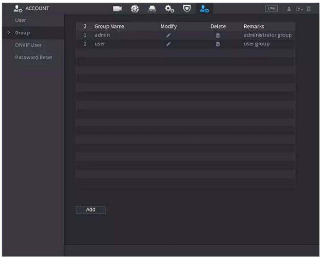
Step 2 Click

for the group account that you want to modify.
Figure 5-304 Modify
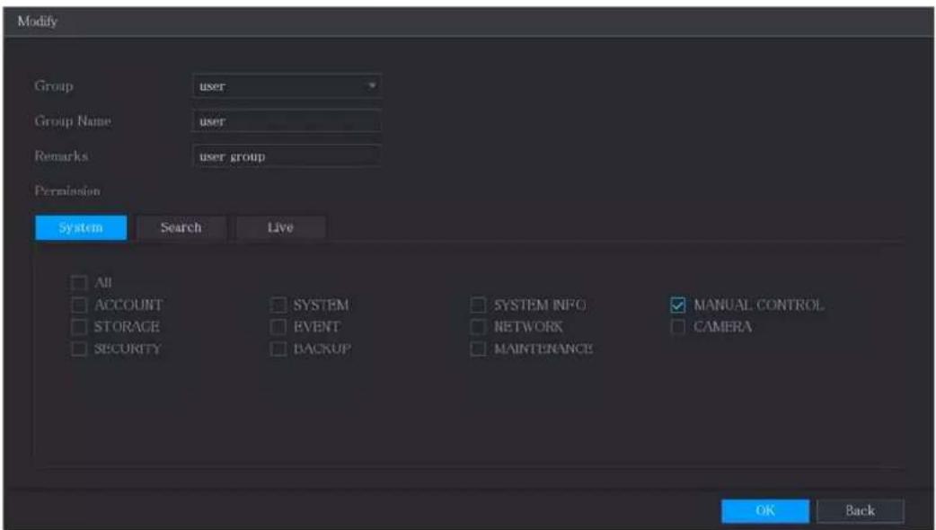
Step 3 Change the settings for group name, memo, and authority.
Step 4 Click OK to complete the settings.
5.16.2.3 Deleting a Group
Step 1 Select Main Menu > ACCOUNT > Group.
Figure 5-305 Group
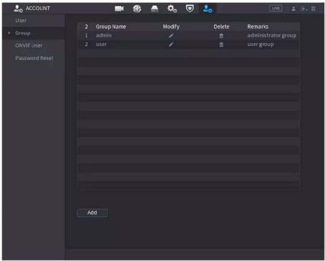
Step 2
Click

for the user account that you want to delete.
Step 3
Click OK to delete a group.
5.16.3 Configuring ONVIF Users
The device manufactured by other company can connect to the Device through ONVIF protocol by an authorized ONVIF account.

The admin account is created for ONVIF users right after the Device has been initialized
Step 1 Select Main Menu > ACCOUNT > ONVIF User.
Figure 5-306 ONVIF user
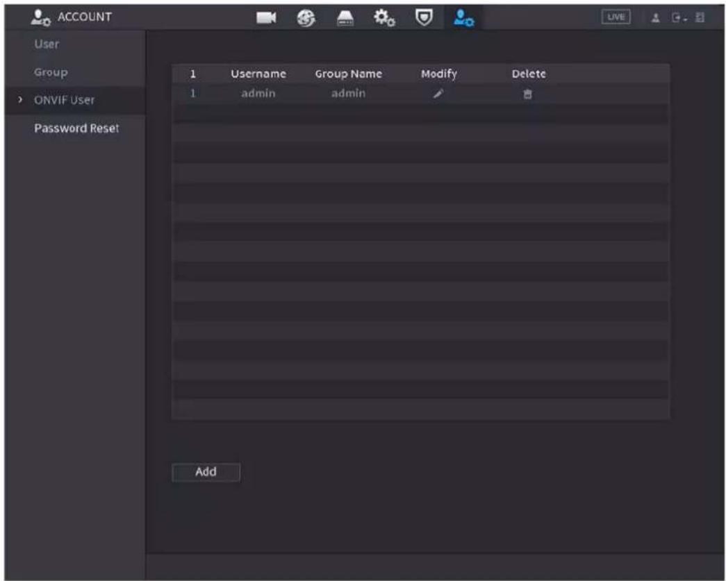
Step 2 Click Add.
Figure 5-307 Add ONVIF user
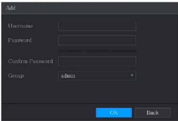
Step 3 Enter username, password, and select the group that you want this account to belong to.
Step 4 Click OK to save the settings.


5.17 Audio Management
Audio management function manages audio files and configures the playing schedule. When there is an alarm event, the audio file can be activated.
5.17.1 Configuring Audio Files
You can add audio files, listen to audio files, rename and delete audio files, and configure the audio volume.
Step 1 Select Main Menu > AUDIO > File Management.
Figure 5-308 File management
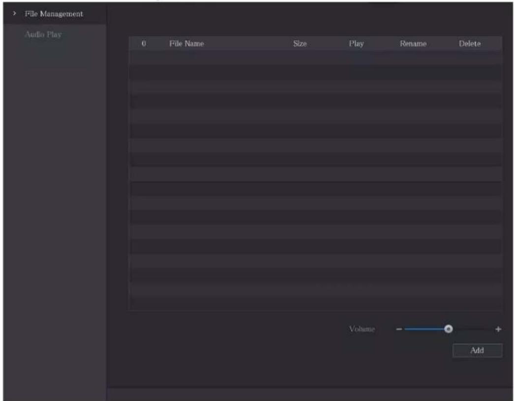
Step 2 Click Add.
Figure 5-309 Add file
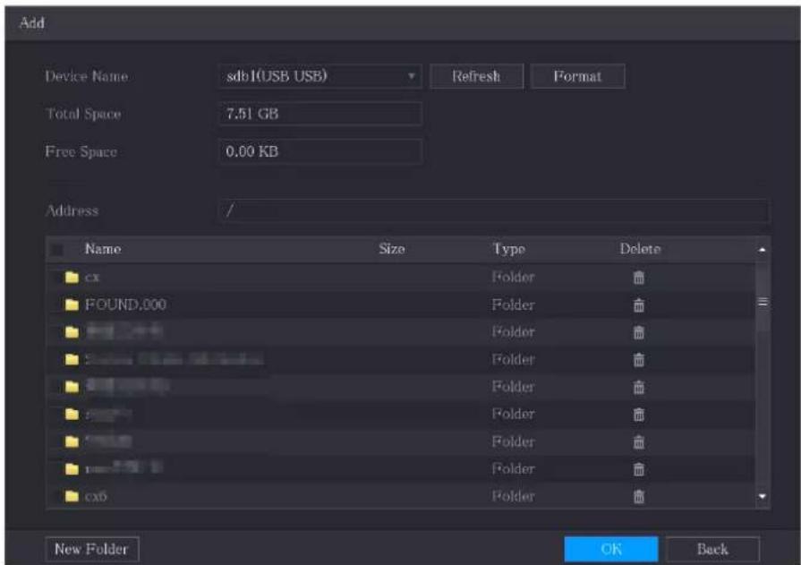
Step 3 Select the audio files that you want to import.
Step 4 Click OK to start importing audio files from the USB storage device.
If the importing is successful, the audio files will display in the File Management page.
Figure 5-310 Imported file
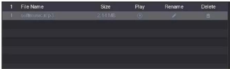
The imported audio files are automatically saved into the HDD, so you do not need to connect to the USB storage device to get the file next time.
- Click to play the audio file.
- Click to rename the audio file.
- Click to delete the audio file.
- To decrease or increase the playing volume, move the slider to the left or to the right.
5.17.2 Configuring Playing Schedule for Audio Files
You can configure the settings to play the audio files during the defined time period.
Step 1 Select Main Menu > AUDIO > Audio Play.
Figure 5-311 Audio play
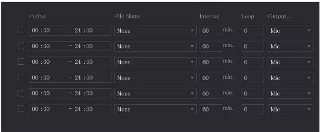
Step 2 Configure the settings for the schedule parameters.
Figure 5-312 Schedule parameters
| Parameter Description | |
| Period | In the Period box, enter the time. Select the checkbox to enable the settings.You can configure up to six periods. |
| File Name | In the File Name list, select the audio file that you want to play for this configured period. |
| Interval | In the Interval box, enter the time in minutes for how often you want to repeat the playing. |
| Repeat | Configure how many times you want to repeat the playing in the defined period. |
| Output Port | Includes two options: MIC and Audio. It is MIC by default. The MIC function shares the same port with talkback function and the latter has the priority. |

- The finish time for audio playing is decided by audio file size and the configured interval.
- Playing priority: Alarm event > Talkback > Trial listening > Audio file.
Step 3 Click Apply to complete the settings.
5.18 Storage Management
Storage management function manages the stored resources such as recorded video files and storage space. The function aims at providing easier operation and improving the storage efficiency.
5.18.1 Configuring Basic Settings
Step 1 Select Main Menu > STORAGE > Basic.
Figure 5-313 Basic
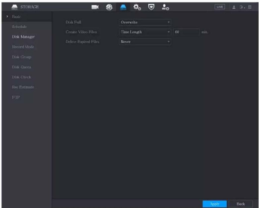
Step 2 Configure the settings for the basic settings parameters.
Table 5-58 Basic settings parameters
| Parameter Description | |
| Disk Full | Configure the settings for the situation all the read/write discs are full.SelectStopto stop recording.SelectOverwriteto overwrite the recorded video files always from the earliest time. |
| Create Video Files | Configure the time length and file length for each recorded video. |
| Delete Expired Files | Configure whether to delete the old files and if yes, configure the days. |
Step 3 Click Apply to complete the settings.
5.18.2 Configuring the Recording and Snapshot Schedule
The system starts recording and taking snapshot according to the configured schedule. For details, see "5.1.4.9 Configuring Recorded Video Storage Schedule" and "5.1.4.10 Configuring Snapshot Storage Schedule".
5.18.3 Configuring Disk Manager
You can view the HDD information, format HDD, and configure the HDD type through HDD manager. Step 1 Select Main Menu > STORAGE > Disk Manager.
In the table, you can view the information of current HDD, such as device name, HDD type, status, total space and free space, and serial number of the HDD port.
Figure 5-314 Disk manager
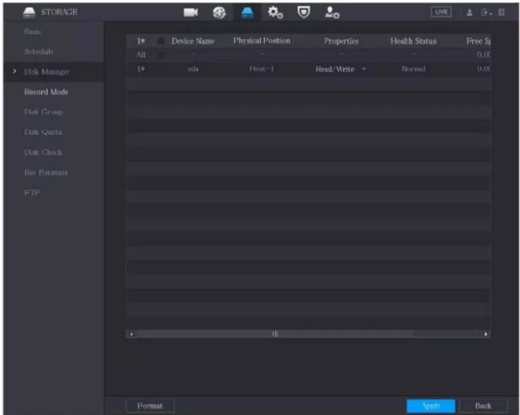
Step 2 Configuring the settings for the HDD manager.
- HDD type setting: In the Properties list, select Read/Write, Read Only, and then click Apply to save the settings.
- HDD format: Select the HDD that you want to format, click Format, and enable Clear HDD database in the pop-up message, click OK and enter the password of admin user in the prompted dialog box, click OK and then following the on-screen instructions to complete formatting.
- Formatting HDD will erase all data on the disk, proceed with caution.
Figure 5-315 Note
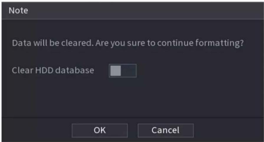
5.18.4 Configuring Record
Record type includes auto and manual record. You can configure record type of main stream and substream. See "5.7 Configuring Record Settings".
5.18.5 Configuring Advance Settings
Create HDD group, and save main stream, sub stream and snapshot of designated channels to the HDD group.

- If the page displays that "Current HDD Mode is Quota Group", click "Change to HDD Group Mode", and then configure HDD group.
- You can enable either HDD Group Mode or Quota Group. The system prompts to reboot the device each time when you switch the mode.
Step 1 Select Main Menu > STORAGE > Disk Group > Disk Group.
Figure 5-316 Disk group
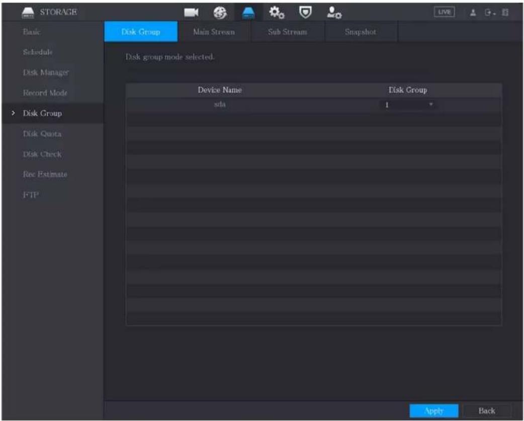
Step 2 Select group for each HDD, and then click Apply to complete the settings.
Step 3 After configuring HDD group, click Main Stream, Sub Stream and Snapshot tabs respectively, to configure the saving of main stream, sub stream and snapshot information of different channels to different HDD groups.
Figure 5-317 Main stream
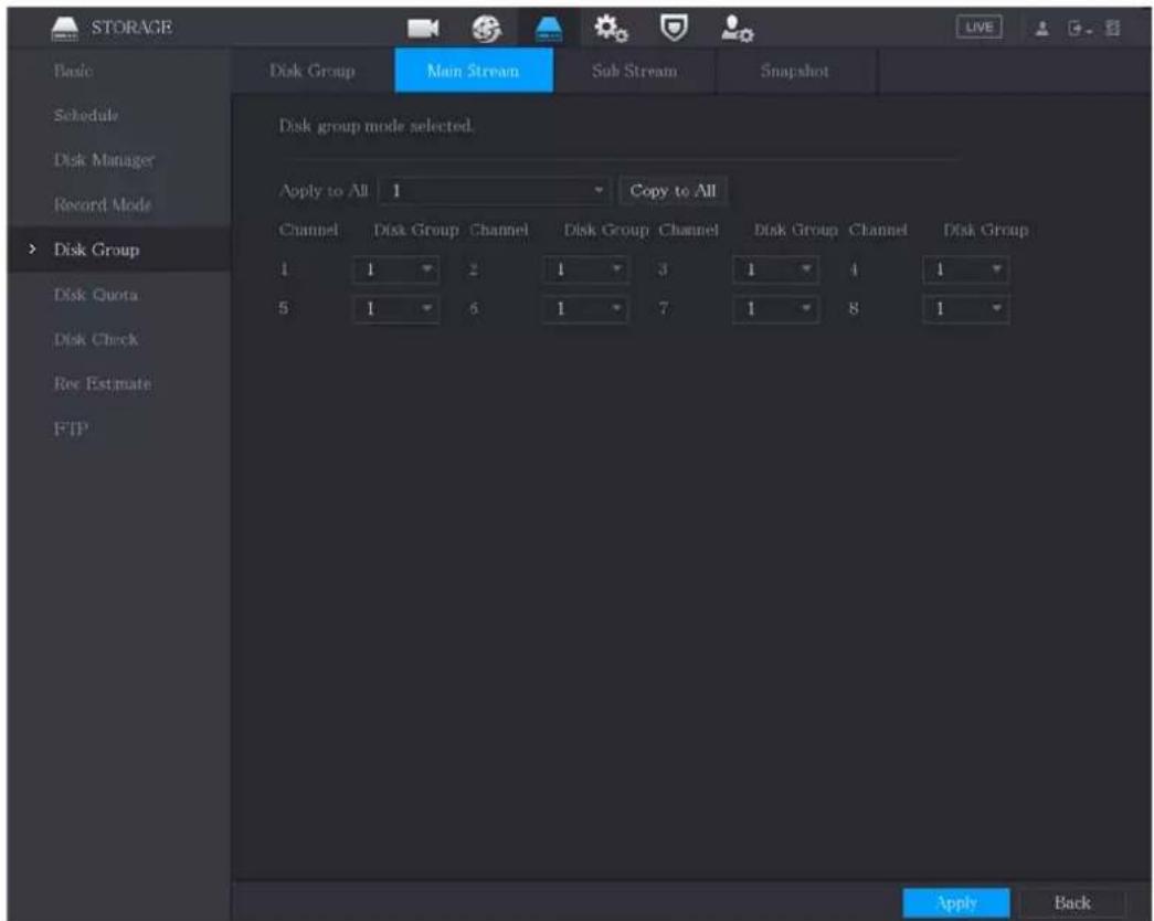
Figure 5-318 Sub stream
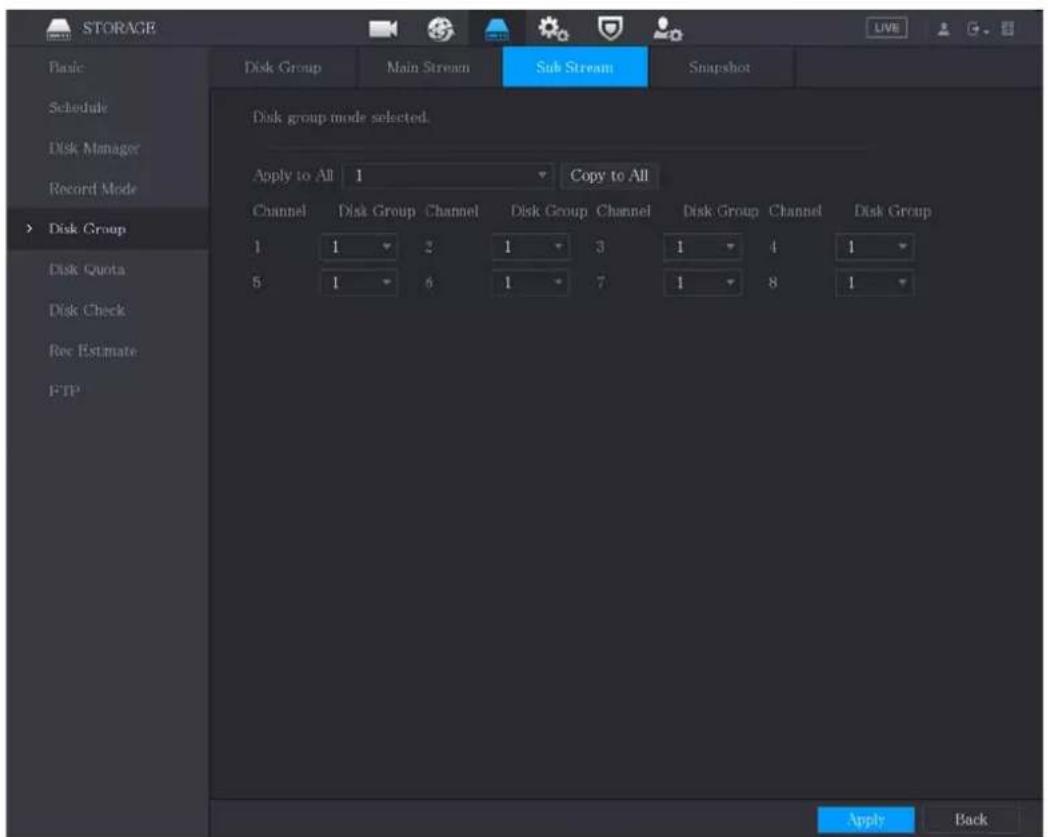
Figure 5-319 Snapshot
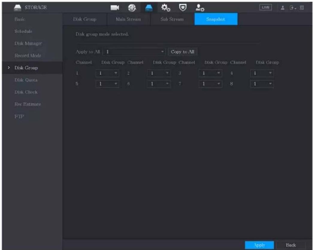
Step 4 Click Apply to complete the settings.
5.18.6 Configuring Disk Quota
By configuring quota, allocate fixed storage capacity to each channel, and distribute the storage space of each channel reasonably.

- If the page displays Disk group mode selected, click Switch to Quota Mode, and then configure quota.
- You can enable either disk group mode or quota mode. The system prompts to restart the device each time when you switch the mode.
Step 1 Select Main Menu > STORAGE > Disk Quota.
Step 2 Configure the disk quota.
- For one-HDD devices, click ☐, select a channel and then configure the parameters including recording duration, bit rate, storage capacity of pictures.
Figure 5-320 Disk quota (one-HDD device)
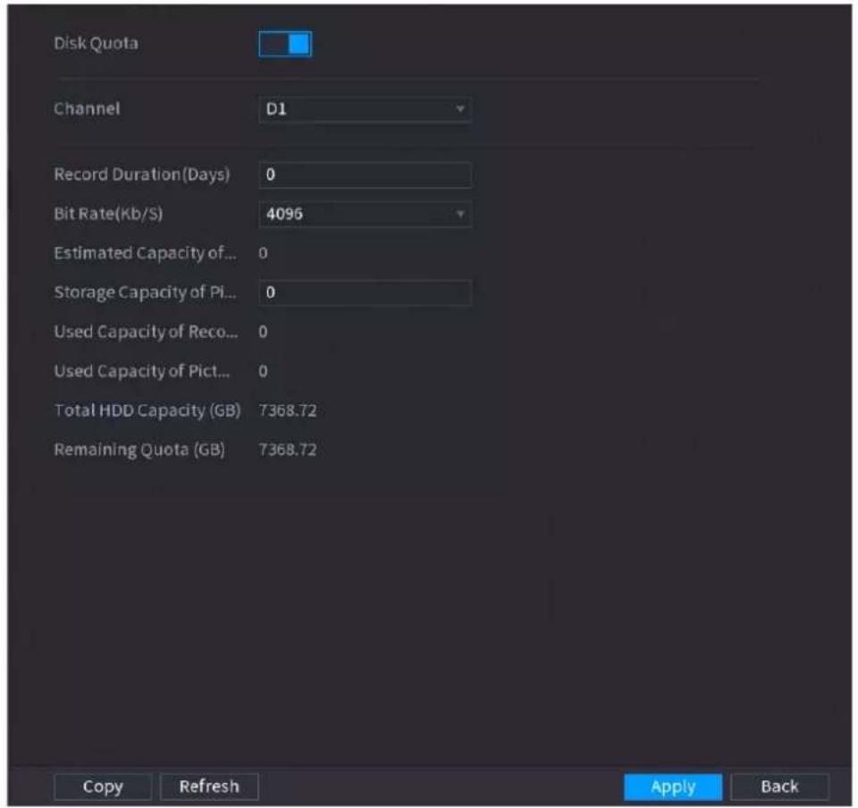
- For devices that support 2 or more HDDs, you can switch the quota mode between version 1 and version 2.
◇ V1: Select a channel and then configure the disk quota for each disk.
V2: Select a channel and then configure the parameters including recording duration, bit rate, storage capacity of pictures.
Figure 5-321 Version 1
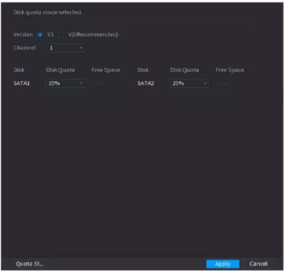
Figure 5-322 Version 2
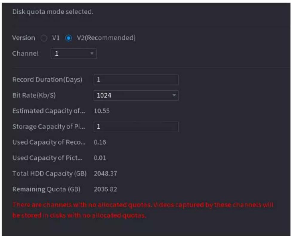
Step 3 Click Apply.
5.18.7 Configuring HDD Detecting Settings

This function is available on select models.
HDD detecting function detects the current status of HDD to let you know the HDD performance and replace the defective HDD.
5.18.7.1 Checking HDD
You can detect HDD by key area detect and global detect.
- Key area detect: Detect the files saved in HDD. The detected bad track can be repaired by formatting. If there are no files in HDD, the system cannot detect the bad track.
- Global detect: Detect the whole HDD through Windows, which takes time and might affect the HDD that is recording the video.
Step 1 Select Main Menu > STORAGE > Disk Check > Manual Check.
Figure 5-323 Manual check
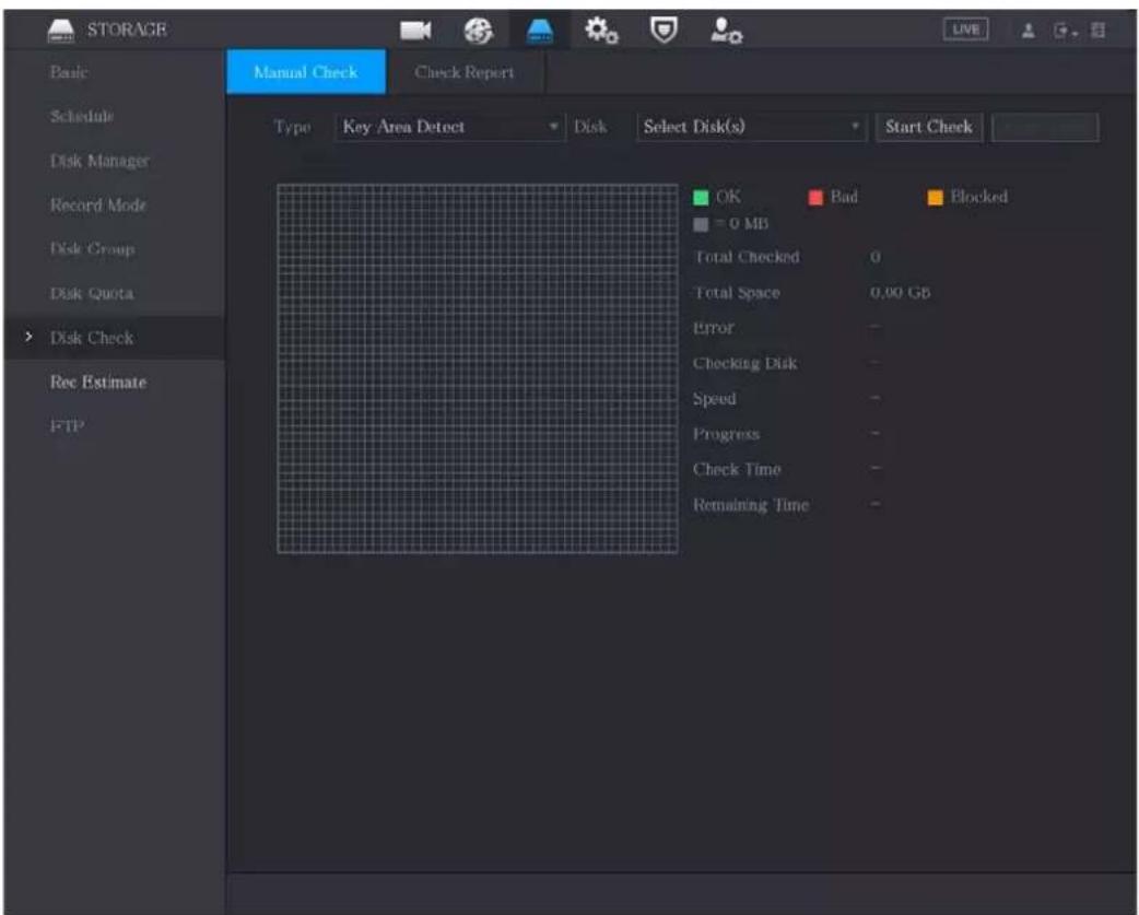
Step 2 In the Type list, select Key Area Detect or Global Check; and in the Disk list, select the HDD that you want to detect.
Step 3 Click Start Check. The system starts detecting the HDD.

During detecting, click Pause to pause detecting, click Continue to restart detecting, and click Stop Detect to stop detecting.
Figure 5-324 Start check
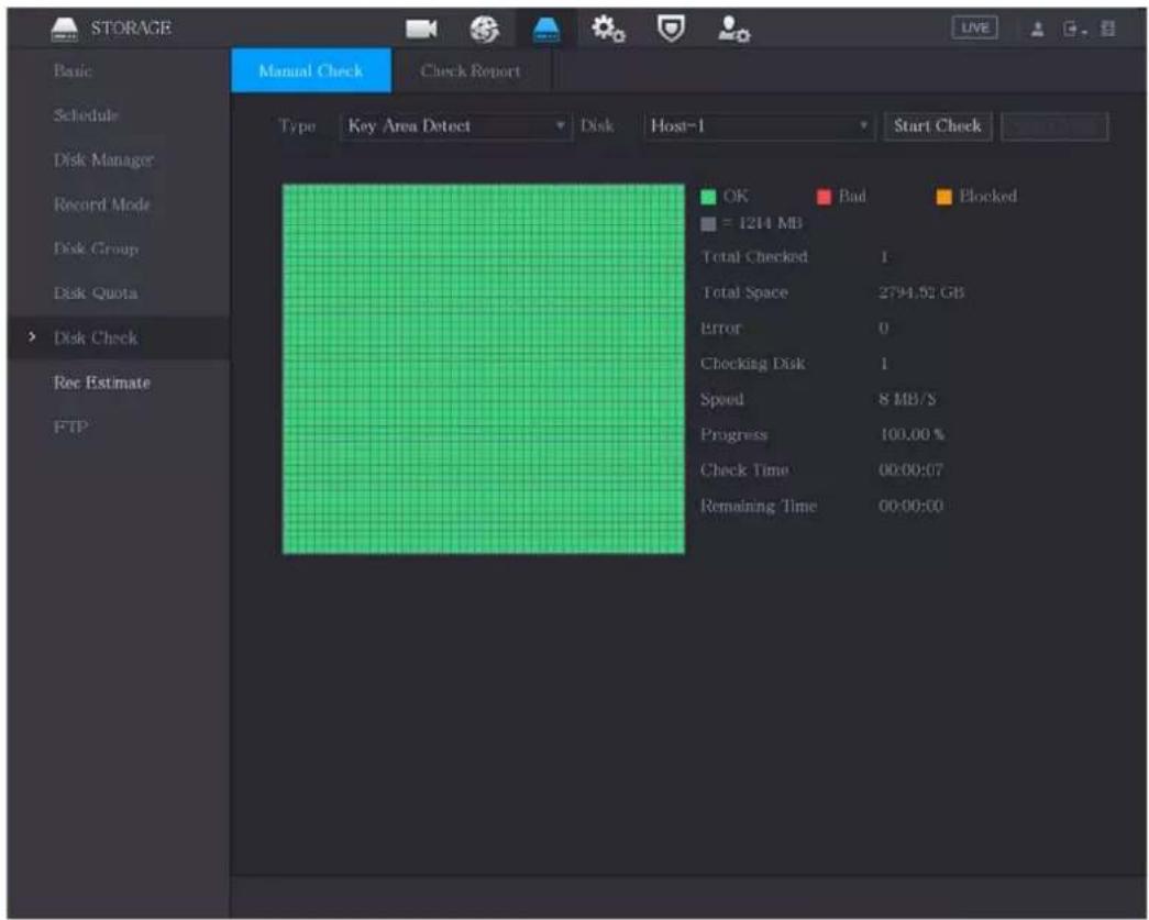
5.18.7.2 View Detecting Results
After the detecting is completed, you can view the detecting reports to find out the problem and replace the defective HDD to avoid data loss.
Step 1 Select Main Menu > STORAGE > Disk Check > Check Report.
Figure 5-325 Check report
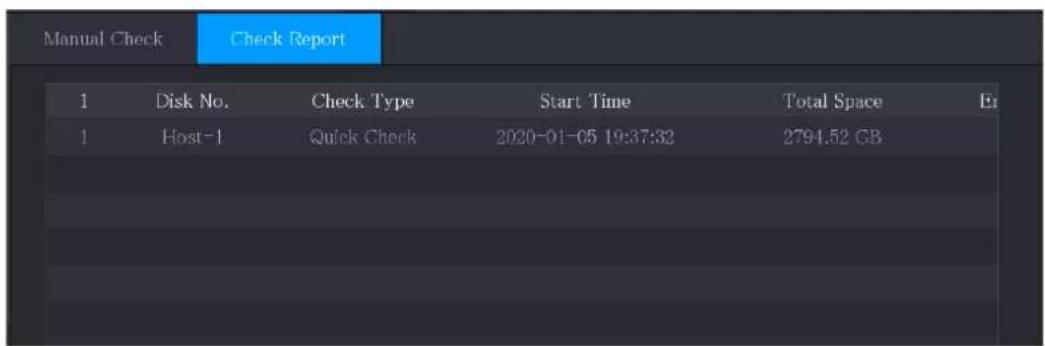
Step 2 Click.

You can view detecting results and S.M.A.R.T reports.
Figure 5-326 Results
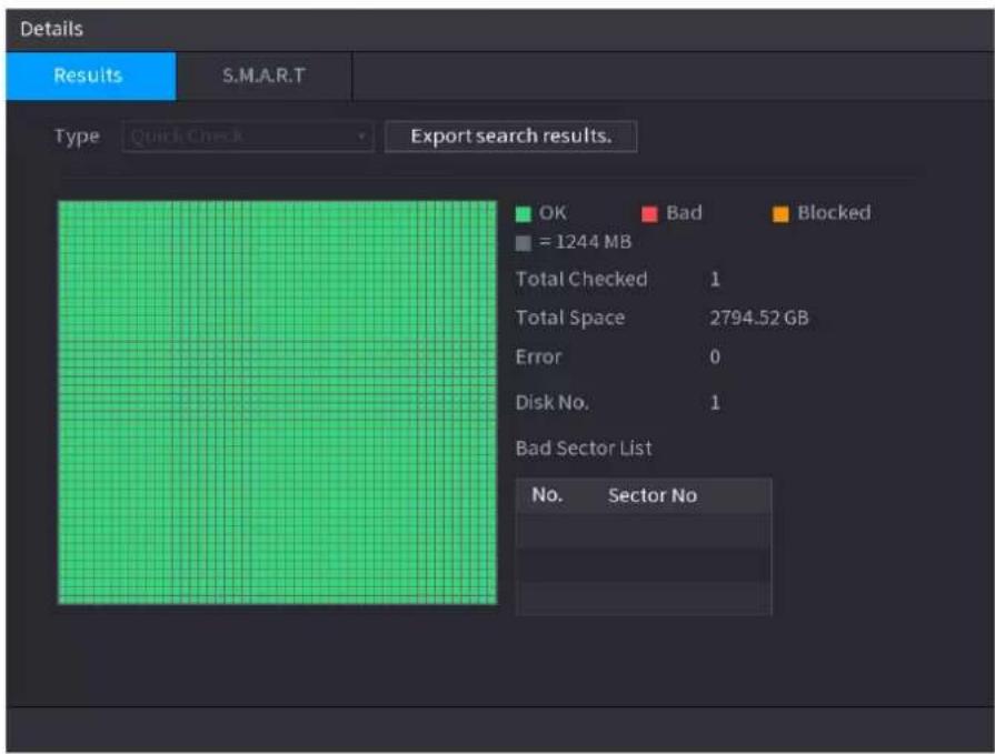
Figure 5-327 S.M.A.R.T
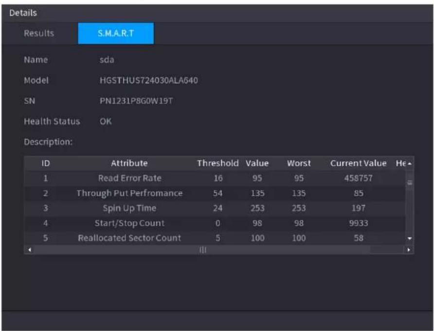
5.18.8 Configuring Record Estimate
Record estimate function can calculate how long you can record video according to the HDD capacity, and calculate the required HDD capacity according to the record period.
Step 1 Select Main Menu > STORAGE > Rec Estimate.
Figure 5-328 Rec estimate
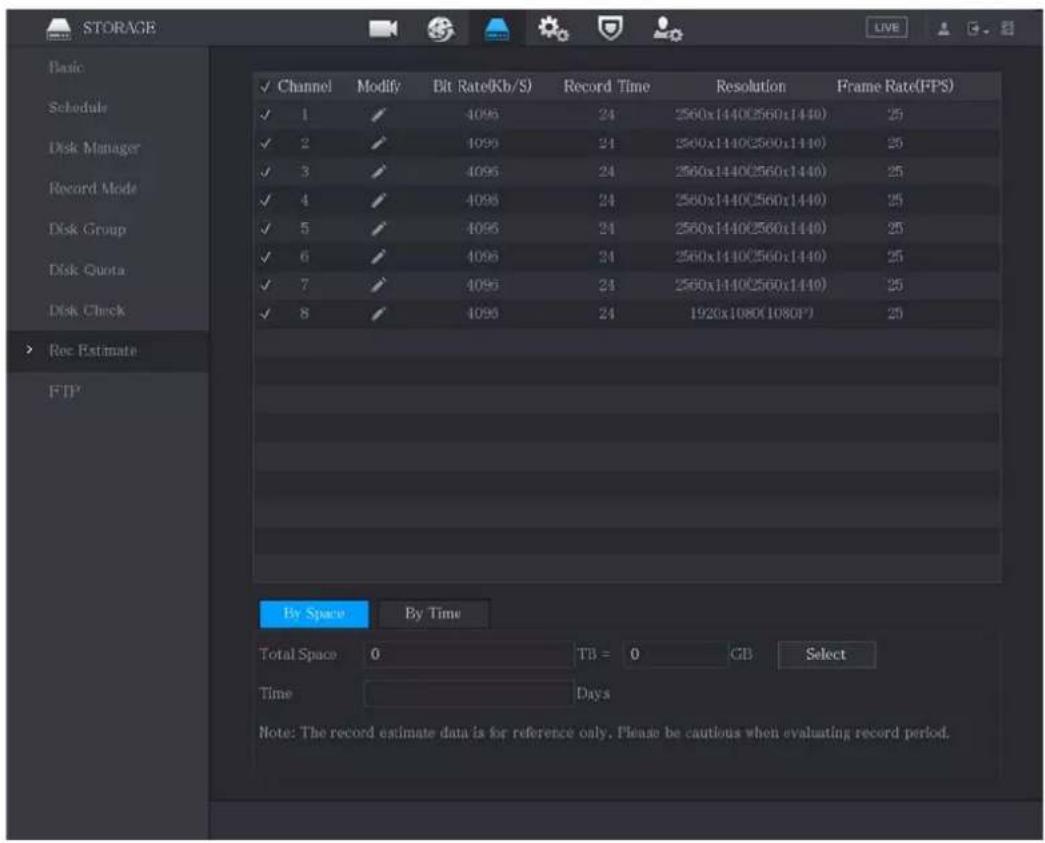
Step 2 Click

You can configure the resolution, frame rate, bit rate and record time for the selected channel.
Step 3 Click OK to save the settings.
Then the system will calculate the time period that can be used for storage according to the channels settings and HDD capacity.

Click Copy to copy the settings to other channels.
Calculating Recording Time
Step 1 On the Rec Estimate page, click the By Space tab.
Figure 5-329 By space
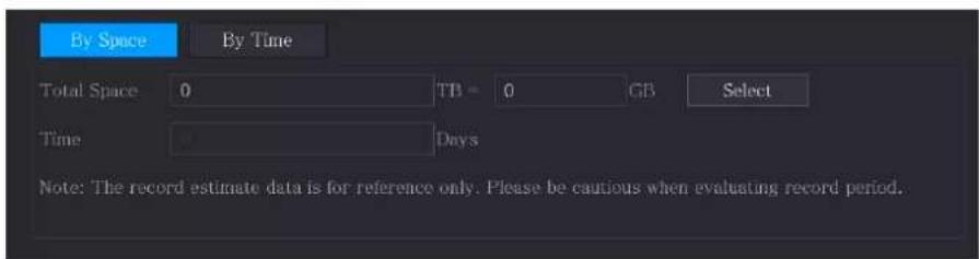
Step 2 Click Select.
Step 3 Select the checkbox of the HDD that you want to calculate.
Figure 5-330 By time
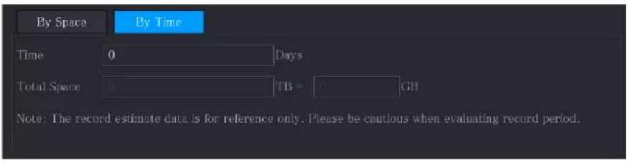
Calculating HDD Capacity for Storage
Step 1 On the Rec Estimate page, click the By Time tab.
Figure 5-331 By time
Step 2 In the Time box, enter the time period that you want to record.
Figure 5-332 Total space
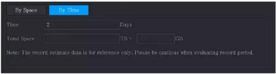
5.18.9 Configuring FTP Storage Settings
You can store and view the recorded videos and snapshots on the FTP server.
Preparation
Purchase or download a FTP server and install it on your PC.

For the created FTP user, you need to set the write permission; otherwise the upload of recorded videos and snapshots might be failed.
Procedure
Step 1 Select Main Menu > STORAGE > FTP.
Figure 5-333 FTP
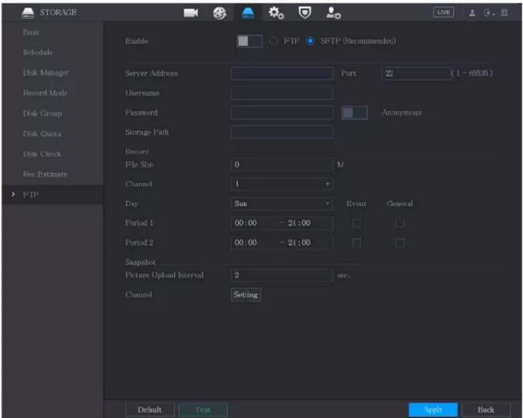
Step 2 Configure the settings for the FTP settings parameters.
Table 5-59 FTP settings parameters
| Parameter Description | |
| Enable | Enable the FTP upload function. |
| FTP type | ● FTP: Plaintext transmission.● SFTP: Encrypted transmission (recommended) |
| Server Address | IP address of FTP server. |
| Port | ● FTP: The default is 21.● SFTP: The default is 22. |
| Anonymous | Enter the username and password to log in to the FTP server. |
| Username | Enable the anonymity function, and then you can login anonymously without entering the username and password. |
| Password | |
| Storage Path | Create folder on FTP server.● If you do not enter the name of remote directory, system automatically creates the folders according to the IP and time.● If you enter the name of remote directory, the system creates the folder with the entered name under the FTP root directory first, and then automatically creates the folders according to the IP and time. |
| File Size | Enter the length of the uploaded recorded video.If the entered length is less than the recorded video length, only a section of the recorded video can be uploaded.If the entered length is more than the recorded video length, the whole recorded video can be uploaded.If the entered length is 0, the whole recorded video will be uploaded. |
| Picture Upload Interval (Sec.) | If this interval is longer than snapshot interval, the system takes the recent snapshot to upload. For example, the interval is 5 seconds, and snapshot interval is 2 seconds per snapshot, the system uploads the recent snapshot every 5 seconds.If this interval is shorter than snapshot interval, the system uploads the snapshot per the snapshot interval. For example, the interval is 5 seconds, and snapshot interval is 10 seconds per snapshot, the system uploads the snapshot every 10 seconds.To configure the snapshot interval, selectMain Menu>CAMERA>Encode>Snapshot. |
| Channel | Select the channel that you want to apply the FTP settings. |
| Day | Select the week day and set the time period that you want to upload the recorded files. You can set two periods for each week day. |
| Period 1, Period 2 | |
| Record type | Select the record type (Alarm, Intel, MD, and General) that you want to upload. The selected record type will be uploaded during the configured time period. |
Step 3 Click Test.
The system pops up a message to indicate success or failure. If failed, check the network connection or configurations.
Step 4 Click Apply to complete the settings.
5.19 Security Center
You can set security options to strengthen device security and use the device in a much safer way.
5.19.1 Security Status
Security scanning helps get a whole picture of device security status. You can scan user, service and security module status for detailed information about the security status of the device.
Detecting User and Service

Green icon represents a healthy status of the scanned item, and orange icon represents a risky status.
- Login authentication: When there's a risk in the login authentication, the icon will be in orange to warn risk. You can click Details to see the detailed risk description.
- Configuration Security: When there's a risk in the device configuration, the icon will be in orange to warn risk. You can click Details to see the detailed risk description.
Figure 5-334 Security status
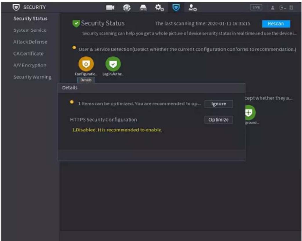
Scanning Security Modules
This area shows the running status of security modules. For details about the security modules, move mouse pointer on the icon to see the on-screen instructions.
Scanning Security Status
You can click Rescan to scan security status.
5.19.2 System Service
You can set DVR basic information such as basic services, 802.1x and HTTPS.
5.19.2.1 Basic Services
Step 1 Select Main Menu > SECURITY > System Service > Basic Services.
Figure 5-335 Basic services
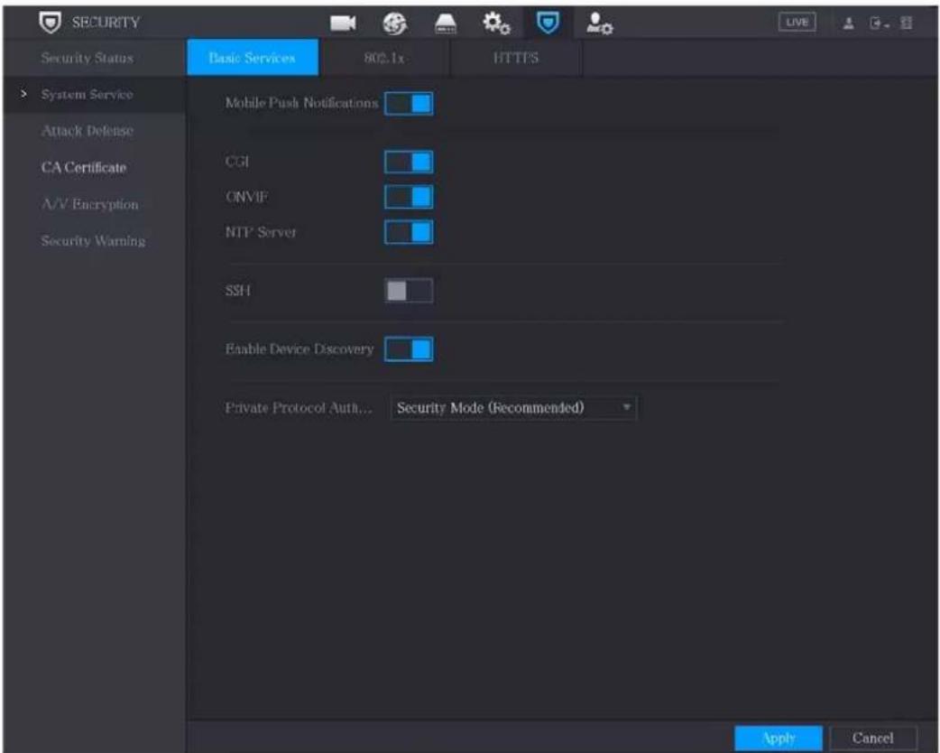
Step 2 Select Basic Services and configure parameters.

There might be safety risk when Mobile Push Notifications, CGI, ONVIF, SSH and NTP Server is enabled.
Table 5-60 Basic services parameters
| Parameter Description | |
| Mobile Push Notifications | After enabling this function, the alarm triggered by the NVR can be pushed to a mobile phone. This function is enabled by default. There might be safety risk if this service is enabled. Disable this function when it is not in use. There might be safety risk if this service is enabled. Disable this function when it is not in use. |
| CGI | If this function is enabled, the remote devices can be added through the CGI protocol. This function is enabled by default. There might be safety risk if this service is enabled Disable this function when it is not in use. There might be safety risk if this service is enabled Disable this function when it is not in use. |
| ONVIF | If this function is enabled, the remote devices can be added through the ONVIF protocol. This function is enabled by default.There might be safety risk if this service is enabled. Disable this function when it is not in use. |
| NTP Server | After enabling this function, a NTP server can be used to synchronize the device. This function is enabled by default. |
| SSH | After enabling this function, you can use SSH service. This function is disabled by default.There might be safety risk if this service is enabled. Disable this function when it is not in use. |
| Enable Device Discovery | After enabling this function, the device can be searched by other devices. |
| Private Protocol Authentication Mode | Security Mode (Recommended): Uses Digest access authentication when connecting to DVR.Compatible Mode: Select this mode when the client does not support Digest access authentication. |
Step 3 Click Apply to complete the settings.
5.19.2.2 802.1x
The device needs to pass 802.1x certification to enter the LAN.
Step 1 Select Main Menu > SECURITY > System Service > 802.1x.
Figure 5-336 802.1x
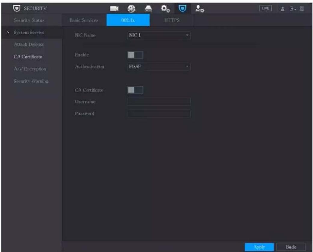
Step 2 Select the Ethernet card you want to certify.
Step 3 Select Enable and configure parameters.
Table 5-61 802.1x parameters
| Parameter Description | |
| NIC Name | Select a NIC. |
| Authentication | PEAP: protected EAP protocol.TLS: Transport Layer Security. Provide privacy and data integrity between two communications application programs. |
| CA Certificate | Enable it and clickBrowseto import CA certificate from flash drive. For details about importing and creating a certificate, see "5.19.4 CA Certificate". |
| Username | The username shall be authorized at server. |
| Password | Password of the corresponding username. |
Step 4 Click Apply to complete the settings.
5.19.2.3 HTTPS
We recommend that you enable HTTPS function to enhance system security.
Step 1 Select Main Menu > SECURITY > System Service > HTTPS.
Figure 5-337 HTTPS
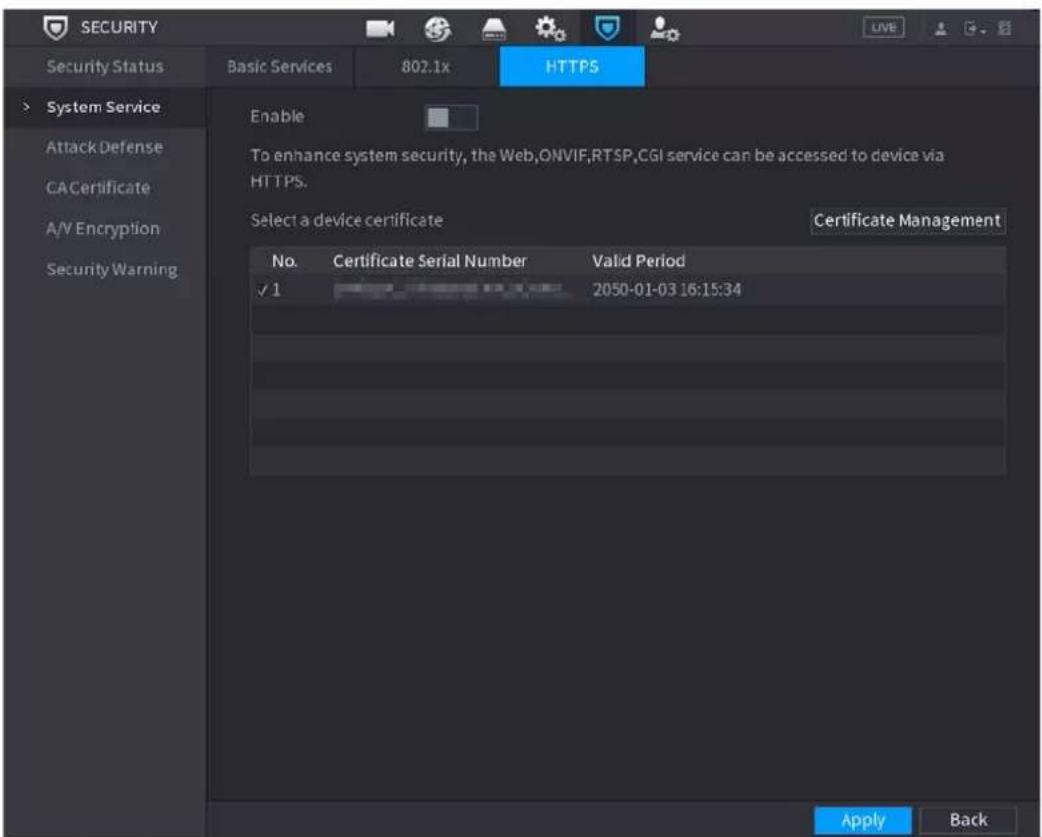
Step 2 Select Enable to enable HTTPS function.
Step 3 Click Certificate Management to create or import a HTTPS certificate from USB drive. For details about importing or creating a CA certificate, see "5.19.4 CA Certificate".
Step 4 Select a HTTPS certificate.
Step 5 Click Apply to complete the settings.
5.19.3 Attack Defense
5.19.3.1 Firewall
Step 1 Select Main Menu > SECURITY > Attack Defense > Firewall.
Step 2 Select Enable to enable firewall.
Step 3 Configure the parameters.
Table 5-62 Firewall parameters
| Parameter Description | |
| Mode | Mode can be configured when Type is Network Access.If Allowlist is enabled, you can visit device port successfully with IP/MAC hosts in the allowlist.If Blocklist is enabled, you cannot visit device port with IP/MAC hosts in blocklist. |
| Add | When Type is Network Access, you can configure IP Address, IP Segment and MAC Address. |
| Type | You can select IP address, IP segment and MAC address. |
| IP Address | Enter IP Address, Start Port and End Port that is allowed or forbidden.When Type is IP Address, they can be configured. Start Port and End Port can be configured only in Network Access Type. |
| Start Port | |
| End Port | |
| Start Address/End Address | Enter Start Address and End Address of IP Segment.When Type is IP Segment, they can be configured. |
| MAC Address | Enter MAC Address that is allowed or forbiddenWhen Type is MAC Address, it can be configured. |
Step 4 Click Apply to complete the settings.
5.19.3.2 Account Lockout
Step 1 Select Main Menu > SECURITY >Attack Defense > Account Lockout.
Figure 5-338 Account lockout
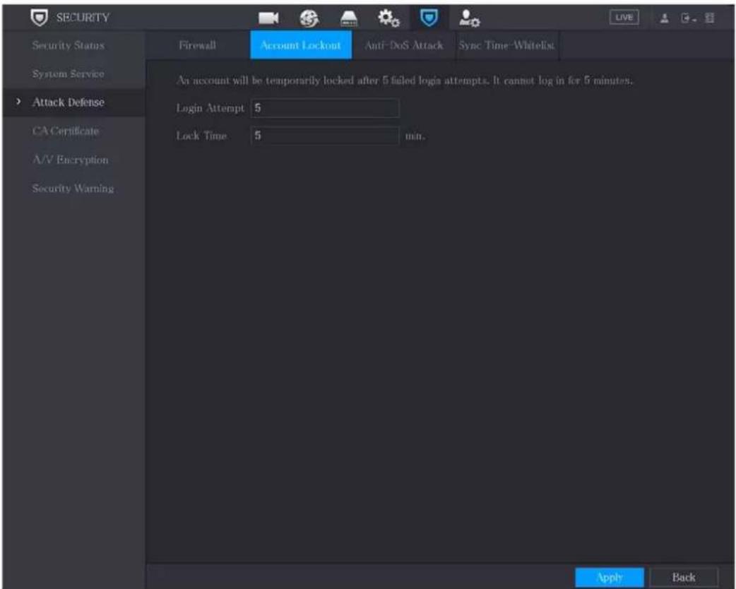
Step 2 Set parameters.
Table 5-63 Lockout parameters
| Parameter Description | |
| Attempt(s) | Set the maximum number of allowable wrong password entries. The account will be locked after your entries exceed the maximum number. Value range: 5–30. Default value: 5. |
| Lock Time | Set how long the account is locked for. Value range: 5–120 minutes. Default value: 5 minutes. |
Step 3 Click Apply to complete the settings.
5.19.3.3 Anti-Dos Attack
You can enable SYN Flood Attack Defense and ICMP Flood Attack Defense to defend the device against Dos attack.
Figure 5-339 Anti-Dos attack
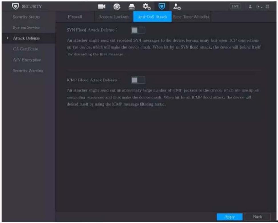
5.19.3.4 Sync Time-Allowlist

The synchronization is only allowed with hosts in the trusted list.
Step 1 Select Main Menu > SECURITY >Attack Defense > Sync Time-Allowlist.
Step 2 Select Enable to enable Sync Time-Allowlist function.
Step 3 Configure the parameters.
Table 5-64 Time-allowlist parameters
| Parameter Description | |
| Add | You can add trusted hosts for time synchronization. |
| Type | Select IP address or IP segment for hosts to be added. |
| IP Address | Input the IP address of a trusted host. When Type is IP Address, it can be configured When Type is IP Address, it can be configured |
| Start Address | Input the start IP address of trusted hosts. When Type is IP Segment, it can be configured When Type is IP Segment, it can be configured |
| End Address | Input the end IP address of trusted hosts. When Type is IP Segment, it can be configured When Type is IP Segment, it can be configured |
Step 4 Click Apply to complete the settings.
5.19.4 CA Certificate
You can create or import device certificate and install trusted CA Certificate.
5.19.4.1 Device Certificate
Create Certificate
Step 1 Select Main Menu > SECURITY > CA Certificate > Device Certificate.

- Click ↓ to download the certificate to local storage.
- Click to delete the certificate. The deleted certificate cannot be restored, proceed with caution.
Figure 5-340 Device certificate
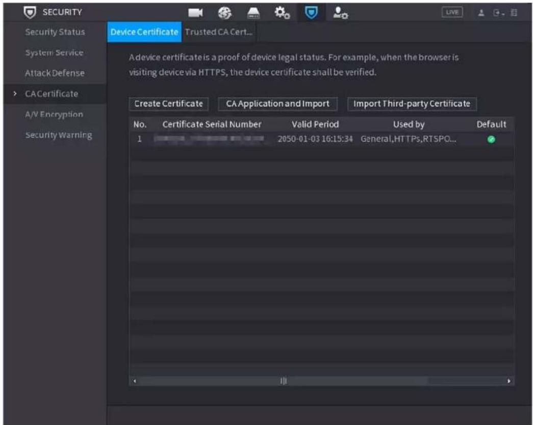
Step 2 Configure parameters.
Table 5-65 Device certificate parameters
| Parameter Description | |
| County | This parameter is user defined. |
| State | This parameter is user defined. |
| City Name | This parameter is user defined. |
| Valid Period | Input a valid period for the certificate. |
| Organization | This parameter is user defined. |
| Organization Unit | This parameter is user defined. |
| Domain Name | Input the IP address of the certificate. |
Step 3 Click Create.
CA Application and Import
Follow the on-screen instructions to finish CA application and import.

Insert a USB flash drive before operating.
Figure 5-341 CA application and import
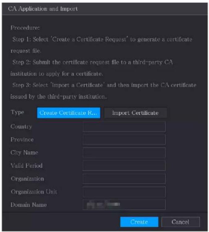
Import Third-Party Certificate
Insert the USB flash drive with third-party certificate before importing.
Step 1 Select Import Third-party Certificate.
Figure 5-342 Import third-party certificate
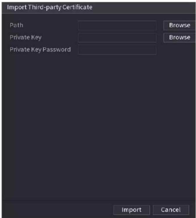
Step 2 Configure Parameters.
Table 5-66 Import third-party certificate
| Parameter Description | |
| Path | ClickBrowseto find the third-party certificate path on the USB drive. |
| Private Key | ClickBrowseto find the third-party certificate private key on the USB drive. |
| Private Key Password | Input the password of encrypted private key. When the private key is not encrypted, you don’t need to this parameter. |
Step 3 Click Create.
5.19.4.2 Trusted CA Certificate
Step 1 Select Main Menu > SECURITY >CA Certificate > Trusted CA Certificate.
Step 2 Click Install Trusted Certificate.
Figure 5-343 Install certificate
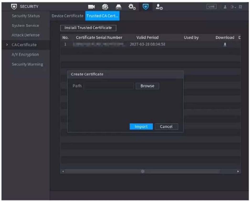
Step 3 Click Browse to select the certificate that you want to install.
Step 4 Click Import.
5.19.5 Audio/Video Encryption
The device supports audio and video encryption during data transmission.
Step 1 Select Main Menu > SECURITY > A/V Encryption > Audio/Video Transmission
Figure 5-344 Audio/video transmission
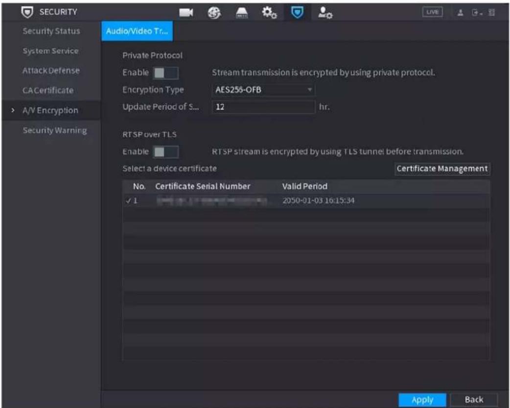
Step 2 Configure parameters.
Table 5-67 Transmission parameters
| Area | Parameter | Description |
| Private Protocol | Enable | Enables stream frame encryption by using private protocol.There might be safety vulnerability if this service is disabled. |
| Encryption Type | Use the default setting. | |
| Update Period of Secret Key | Secret key update period.Value range: 0–720 hours. 0 means never update the secret key.Default value: 12. | |
| RTSP over TLS | Enable | Enables RTSP stream encryption by using TLS.There might be data breach if this service is disabled. We recommend that you enable this function. |
| Select a device certificate | Select a device certificate for RTSP over TLS. | |
| Certificate Management | For details about certificate management, see "5.19.4.1 Device Certificate". |
Step 3 Click Apply to complete the settings.
5.19.6 Security Warning
5.19.6.1 Security Exception
Step 1 Select Main Menu > SECURITY > Security Warning > Security Exception.
Figure 5-345 Security exception
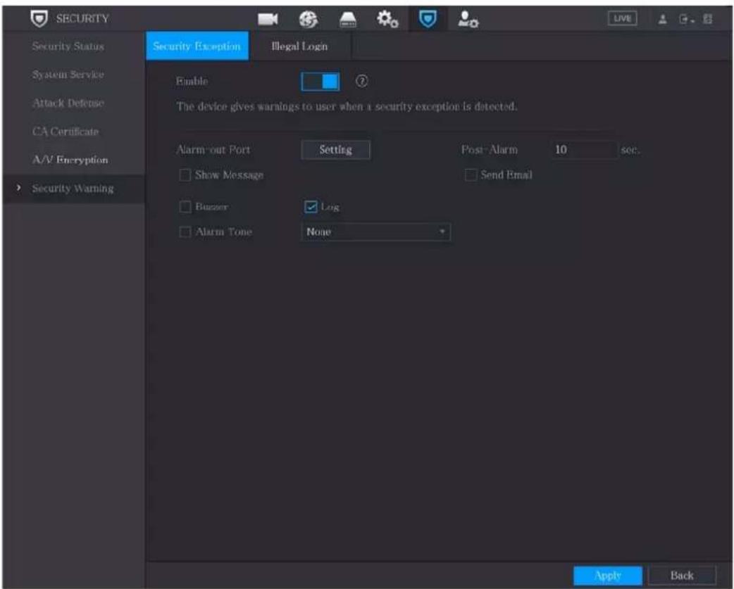
Step 2 Select Enable and configure parameters.
Table 5-68 Security exception parameters
| Parameter Description | |
| Alarm-out Port | The alarm device (such as lights, sirens, etc.) is connected to the alarm output port. When an alarm occurs, the NVR device transmits the alarm information to the alarm device. |
| Post-Alarm | When the alarm ends, the alarm extended for a period of time. The time range is from 0 seconds to 300 seconds. |
| Show Message | Checkbox to enable a pop-up message in your local host PC. |
| Buzzer | Select the checkbox to activate the buzzer when an alarm occurs. |
| Alarm Tone | Check the box and then select the corresponding audio file from the dropdown list. System plays the audio file when the alarm occurs.See "5.17 Audio Management" to add audio file first. |
| Log | Select the checkbox, the NVR device records the alarm information in the log when an alarm occurs. |
| Send Email | Select the checkbox. When an alarm occurs, the NVR device sends an email to the set mailbox to notify the user.To use this function, make sure the email function is enabled inMain Menu > NETWORK > Email. |
 | Security Event monitoring explanation. It indicates the type of attacks that can trigger security exception.Unauthorized executable program trying to runWeb URL brute-force attackSession connection overloadSession ID brute-force attack |
Step 3 Click Apply to complete the settings.
5.19.6.2 Illegal Login
Step 1 Select Main Menu > SECURITY > Security Warning > Illegal Login.
Figure 5-346 Illegal login
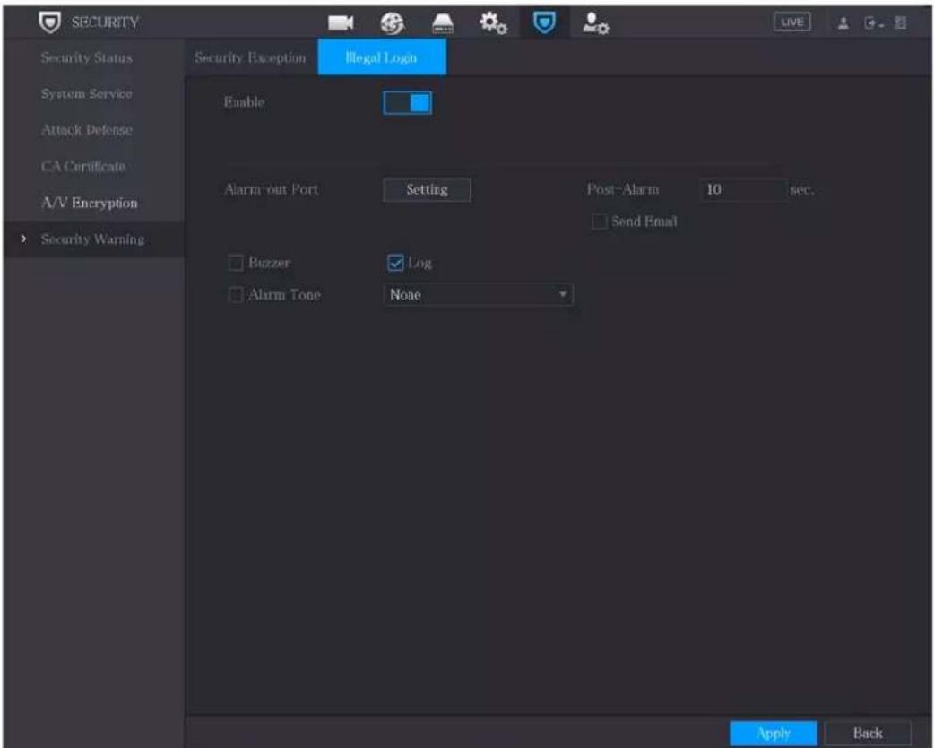
Step 2 Select Enable and configure parameters.
Table 5-69 Illegal login parameters
| Parameter Description | |
| Alarm-out Port | The alarm device (such as lights, sirens) is connected to the alarm output port. When an alarm occurs, the NVR device transmits the alarm information to the alarm device. |
| Post-Alarm | When the alarm ends, the alarm extended for a period of time. The time range is from 0 seconds through 300 seconds. |
| Buzzer | Select the checkbox to activate the buzzer when an alarm occurs. |
| Alarm Tone | Check the box and then select the corresponding audio file from the dropdown list. System plays the audio file when the alarm occurs.[xK7k]See "5.17 Audio Management" to add audio file first |
| Log | Select the checkbox, the NVR device records the alarm information in the log when an alarm occurs. |
| Send Email | Select the checkbox. When an alarm occurs, the NVR device sends an email to the set mailbox to notify the user.To use this function, make sure the email function is enabled inMain Menu >NETWORK >Email. |
5.20 Configuring System Settings
5.20.1 Configuring General System Settings
You can configure the device basic settings, time settings, and holiday settings.
To configure the holiday settings, do the following:
Step 1 Select Main Menu > SYSTEM > General > Holiday.
Figure 5-347 Holiday
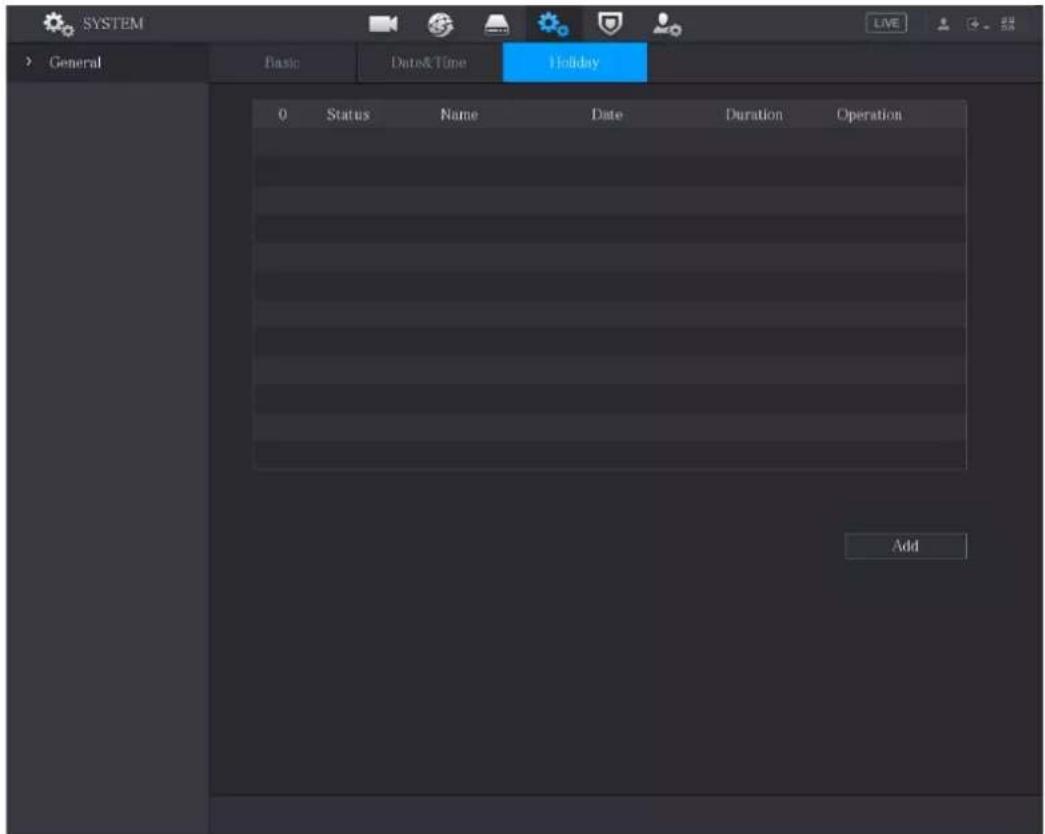
Step 2 Click Add.
Figure 5-348 Add holiday
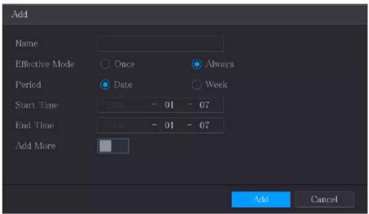
Step 3 Configure the holiday name, repeat mode, time range according to your actual situation.
Step 4 Click Add.

Enable the Add More function, so you can continue adding holiday information.
Figure 5-349 Added holiday
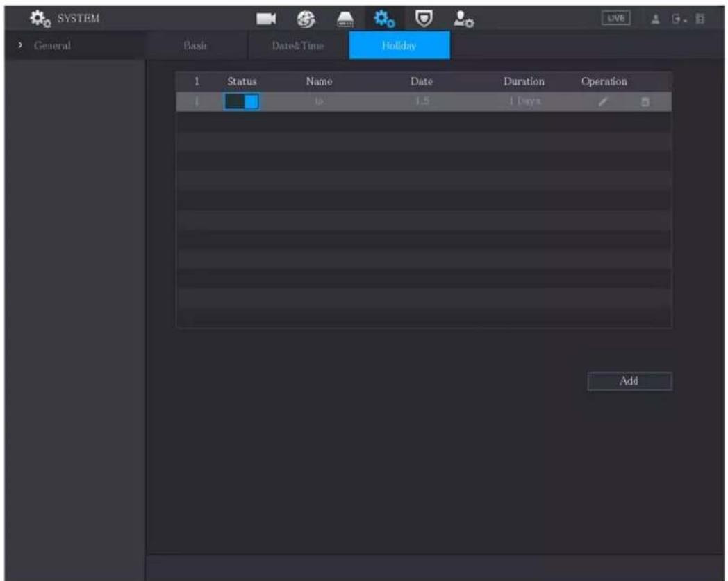
5.20.2 Configuring RS-232 Settings
You can configure serial port function, Baud rate and other parameters.

Only some series products support this RS-232.
Select Main Menu > SYSTEM > RS232.
Figure 5-350 RS-232
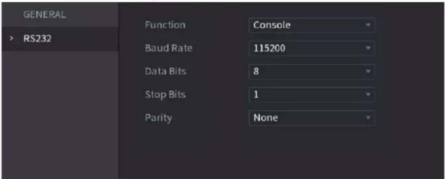
Table 5-70 RS-232 parameters
| Parameter Description | |
| Function | Select serial port control protocol.● Console: Upgrade the program and debug with the console and mini terminal software.● Keyboard: Control this Device with special keyboard.● Adapter: Connect with PC directly for transparent transmission of data.● Protocol COM: Configure the function to protocol COM, in order to overlay card number.● PTZ Matrix: Connect matrix control.It isConsoleby default. |
| Baud Rate | Select Baud rate, which is 115200 by default. |
| Data Bits | It ranges from 5 to 8, which is 8 by default. |
| Stop Bits It includes 1 and 2. | |
| Parity | It includes none, odd, even, mark and null. It is none by default. |
5.20.3 Configuring System Maintenance Settings
When the Device has been running for a long time, you can configure the auto reboot when the Device is not working. You can also configure the case fan mode to reduce noise and extend the service life.
Step 1 Select Main Menu > MAINTAIN > Manager > Maintenance.
Figure 5-351 Maintenance
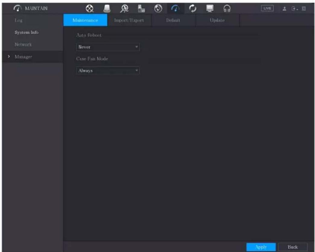
Step 2 Configure the settings for the system maintenance parameters.
Table 5-71 Maintenance parameters
| Parameter Description | |
| Auto Reboot | In theAuto Rebootlist, select the reboot time. |
| Case Fan Mode | In theCase Fan Modelist, you can selectAlwaysorAuto. If you selectAuto, the case fan will stop or start according to the external conditions such as the Device temperature.This function is available on select models, and it is only supported on the local configuration page. |
Step 3 Click Apply to complete the settings.
5.20.4 Exporting and Importing System Settings
You can export or import the Device system settings if there are several Devices that require the same setup.

- The IMP/EXP page cannot be opened if the backup operation is ongoing on the other pages.
- When you open the IMP/EXP page, the system refreshes the devices and sets the current directory as the first root directory.
- Click Format to format the USB storage device.
Exporting System Settings
Step 1 Select Main Menu > MAINTAIN > Manager > Import/Export.
Figure 5-352 Import/Export
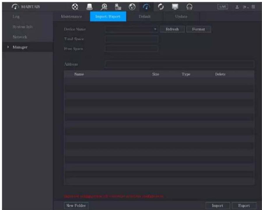
Step 2 Insert a USB storage device into one of the USB ports on the Device.
Step 3 Click Refresh to refresh the page.
Figure 5-353 Connected device
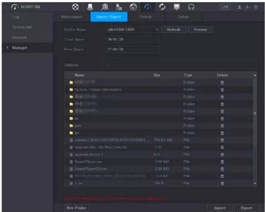
Step 4 Click Export.
There is a folder under the name style of "Config_[YYYYMMDDhhmmss]". Double-click this folder to view the backup files.
Importing System Settings
Step 1 Insert a USB storage device containing the exported configuration files from another Device) into one of the USB ports on the Device.
Step 2 Select Main Menu > SYSTEM > Import/Export.
Step 3 Click Refresh to refresh the page.
Step 4 Click on the configuration folder (under the name style of "Config_[YYYYMMDDhhmmss]") that you want to import.
Step 5 Click Import.
The Device will reboot after the imported is succeeded.
5.20.5 Restoring Default Settings

Only Admin account supports this function.
You can select the settings that you want to restore to the factory default.
Step 1 Select Main Menu > MAINTAIN > Manager > Default.
Figure 5-354 Default
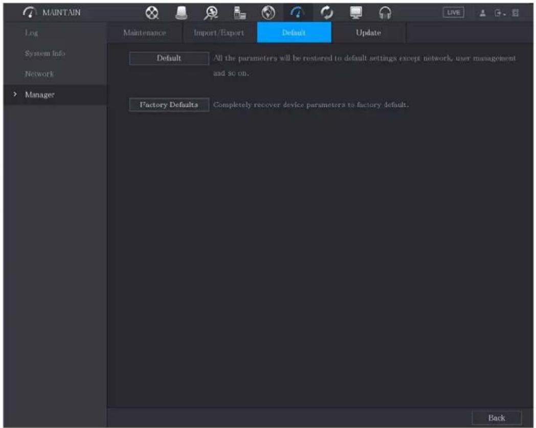
Step 2 Restore the settings.
- Click Default to restore all parameters to default settings except parameters such as network, user management.
- Click Factory Default, select OK and then enter the password of admin user in the prompted dialog box to completely recover device parameters to factory default.
5.20.6 Updating the Device
5.20.6.1 Updating File
Step 1 Insert a USB storage device containing the upgrade files into the USB port of the Device. Step 2 Select Main Menu > MAINTAIN > Manager > Update.
Figure 5-355 Update
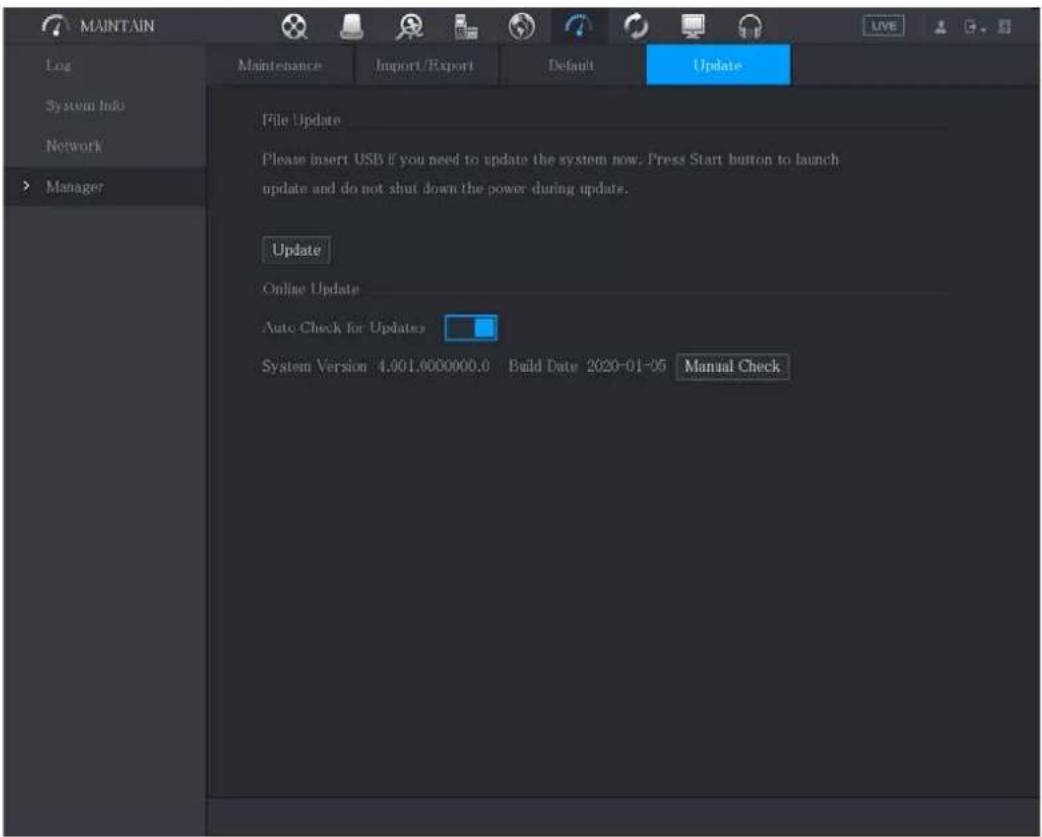
Step 3 Click Update.
Figure 5-356 Browse
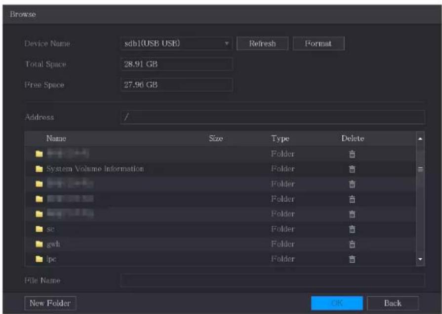
Step 4 Click the file that you want to upgrade.
Step 5 Click OK.
5.20.6.2 Performing Online Upgrade
When the Device is connected to Internet, you can use online upgrade function to upgrade the system. Before using this function, you need to check whether there is any new version by auto check or manual check.
• Auto check: The Device checks if there is any new version available at intervals.
- Manual check: Perform real-time check whether there is any new version available.

Ensure the correct power supply and network connection during upgrading; otherwise the upgrading might be failed.
Step 1 Select Main Menu > MAINTAIN > Manager > Update.
Figure 5-357 Update
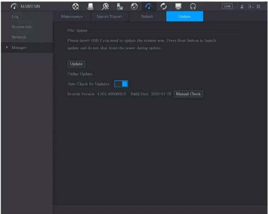
Step 2 Check whether there is any new version available.
• Auto check: Enable Auto-check for updates.
• Manual check: Click Manual Check.
The system starts checking the new versions. After checking is completed, the check result is displayed.
- If the "It is the latest version" text is displayed, you do not need to upgrade.
- If the text indicating there is a new version, go the step 3.
Step 3 Click Upgrade now.
5.20.6.3 Uboot Upgrading

- Under the root directory in the USB storage device, there must be "u-boot.bin.img" file and "update.img" file saved, and the USB storage device must be in FAT32 format.
• Make sure the USB storage device is inserted; otherwise the upgrading cannot be performed.
When starting the Device, the system automatically checks whether there is a USB storage device connected and if there is any upgrade file, and if yes and the check result of the upgrade file is correct, the system will upgrade automatically. The Uboot upgrade can avoid the situation that you have to upgrade through +TFTP when the Device is halted.
5.20.7 Exporting Intelligent Diagnosis Data
When an error occurs, go to Main Menu > MAINTAIN > Intelligent Diagnosis to export intelligent diagnosis data for troubleshooting. The maintenance tasks, such as the import and export of configuration, can be performed in COS Pro Portal. For details, see the corresponding user's manual.
5.21 Viewing Information
You can view the information such as log information, HDD information, and version details
5.21.1 Viewing Version Details
You can view the version details such as device model, system version, and build date.
Select Main Menu > INFO > VERSION.
Figure 5-358 Version
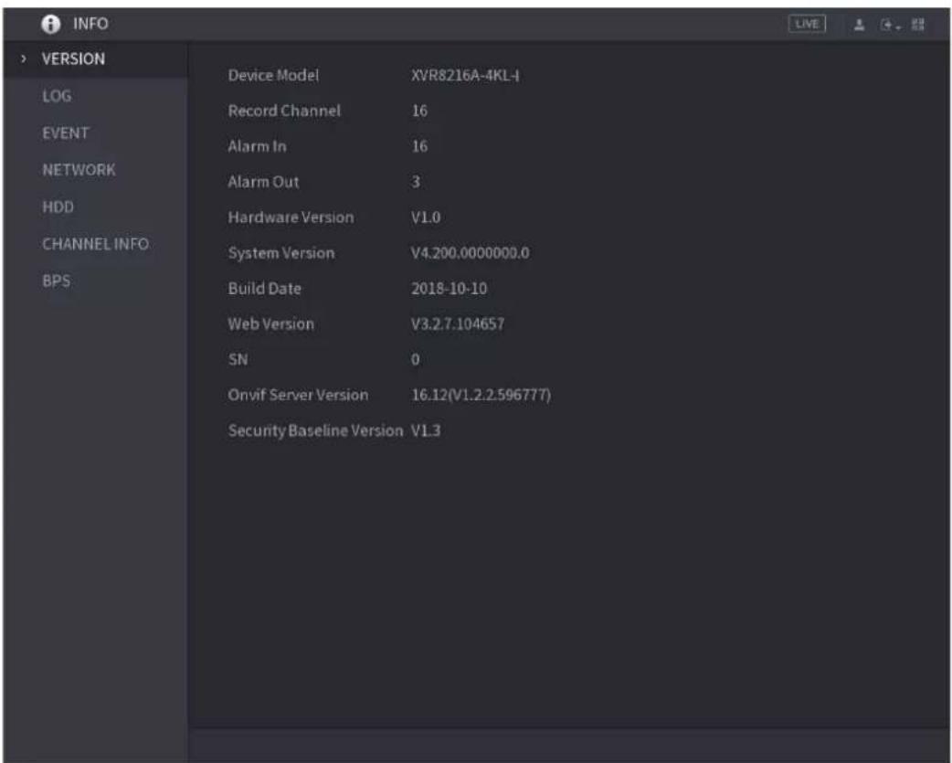
5.21.2 Viewing Log Information
You can view and search the log information.

- If there is HDD installed, the logs about system operations are saved in the memory of the Device and other types of logs are saved into the HDD. If there is no HDD installed, the other types of logs are also saved in the memory of the Device.
- When formatting the HDD, the logs will not be lost. However, if you take out the HDD from the Device, the logs might be lost.
Step 1 Select Main Menu > INFO > LOG.
Figure 5-359 Log
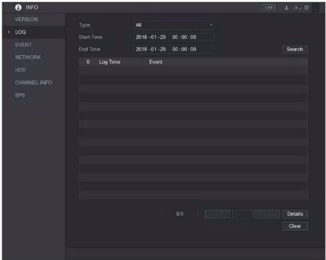
Step 2 In the Type list, select the log type that you want to view (System, Config, Storage, Record, Account, Clear, Playback, and Connection) or select All to view all logs.
Step 3 In the Start Time box and End Time box, enter the time period to search, and then click Search.
The search results are displayed.
Figure 5-360 Search results
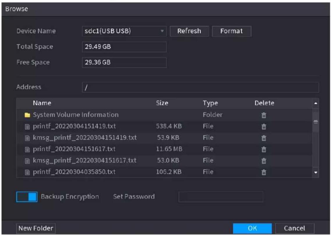

- Click Details or double-click the log that you want to view, the Detailed Information page is displayed. Click Next or Previous to view more log information.
- Click Backup to back up the logs into the USB storage device. You can enable Backup Encryption and then set a password. The password is required to open the exported file.
- Click Clear to remove all logs.
5.21.3 Viewing Event Information
You can view the event information of the Device and channel.
Select Main Menu > INFO > EVENT, the EVENT page is displayed.
Figure 5-361 Event
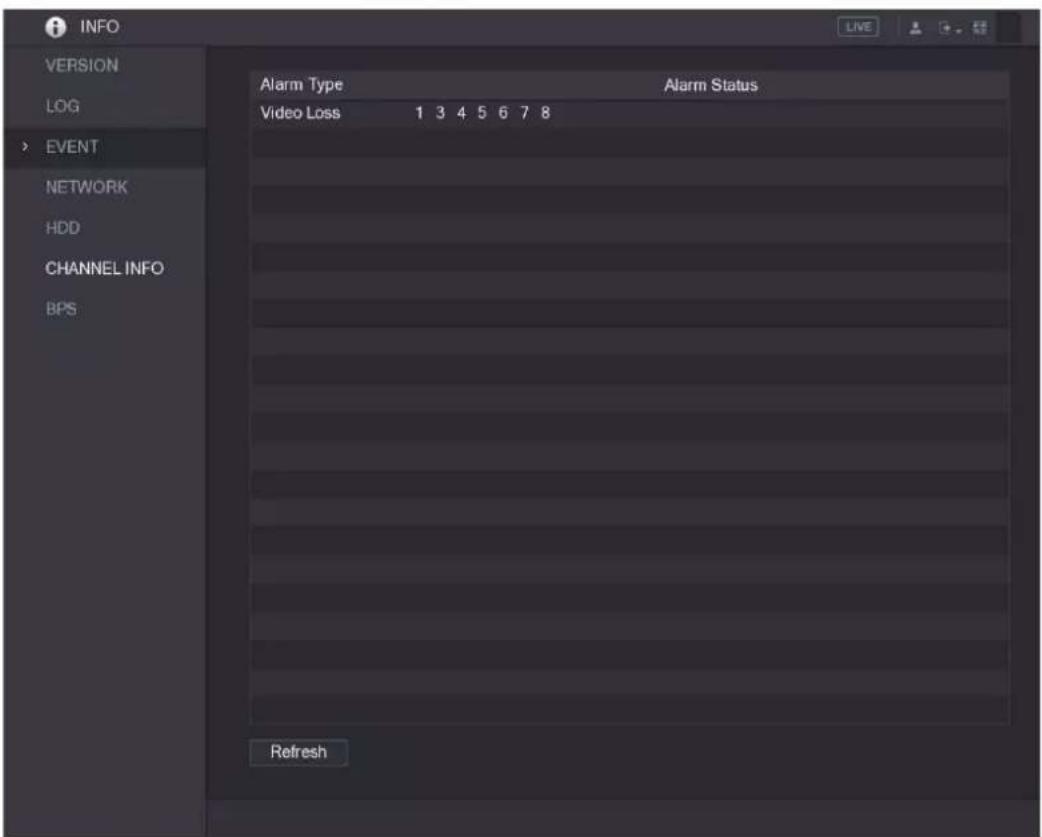
5.21.4 Viewing Network Information
You can view the online users, network data transmission details, and test network. For details about testing network, see "5.15.2.1 Testing the Network".
5.21.4.1 Viewing Online Users
You can view the online user information and block any user for a period of time.
Select Main Menu > INFO > NETWORK > Online users, the Online users page is displayed.
Figure 5-362 Online user
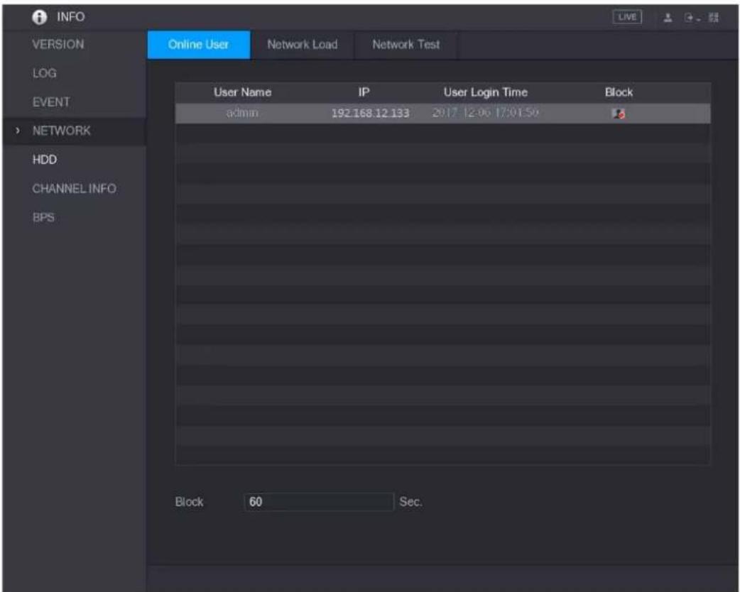
To block an online user, click 📋 and then enter the time that you want to block this user. The maximum value you can set is 65535.
The system detects every 5 seconds to check whether there is any user added or deleted, and update the user list timely.
5.21.4.2 Viewing the Network Load
Network load means the data flow which measures the transmission capability. You can view the information such as data receiving speed and sending speed.
Step 1 Select Main Menu > INFO > NETWORK > Network Load.
Figure 5-363 Network load
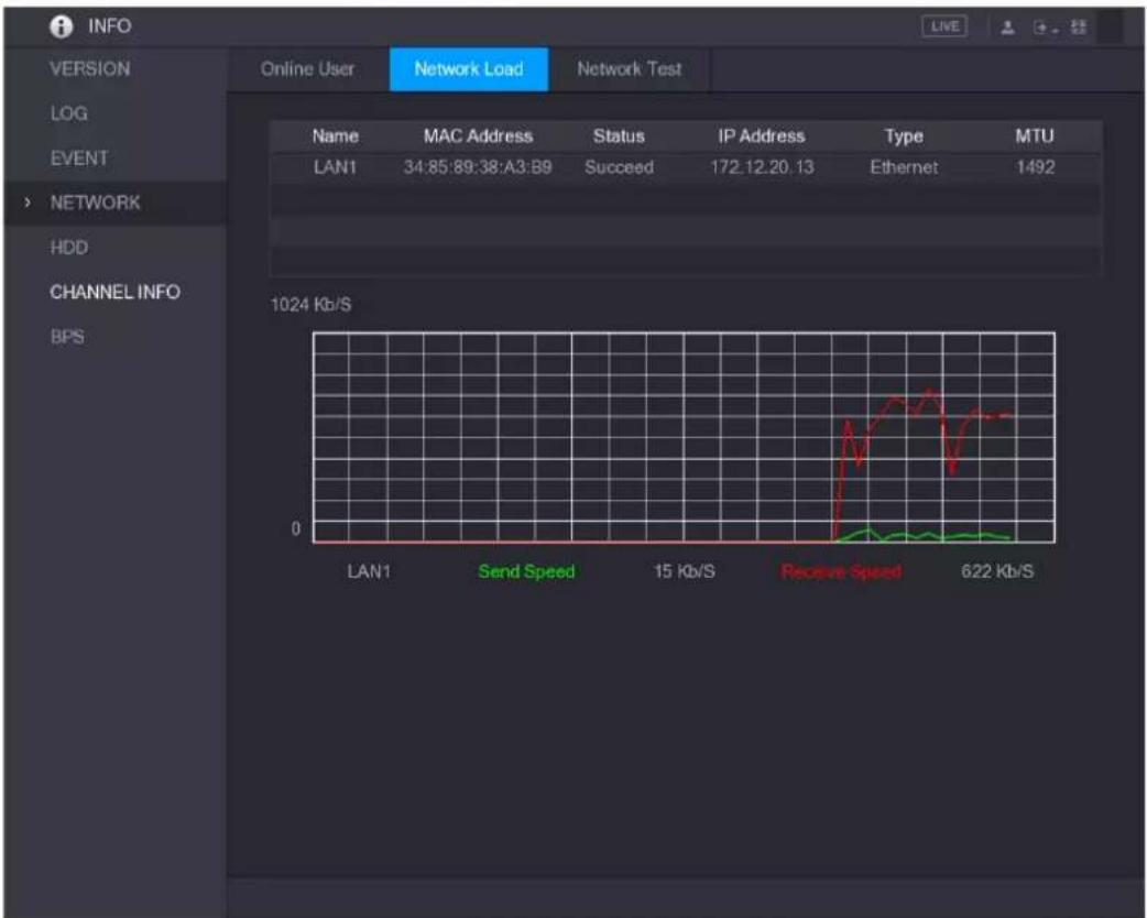
line
| Time (Gb/S) | MAC Address Status | IP Address Status | |-------------|--------------------|-------------------| | 0 | 0 | 0 | | 15 | 0 | 0 | | 622 | 0 | 0 |Step 2 Click the LAN name that you want to view, for example, LAN1.
The system displays the information of data sending speed and receiving speed.

• The default display is LAN1 load.
- Only one LAN load can be displayed at one time.
5.21.5 Viewing HDD Information
You can view the HDD quantity, HDD type, total space, free space, status, and S.M.A.R.T information. Select Main Menu > INFO > HDD, the HDD page is displayed.
Figure 5-364 HDD
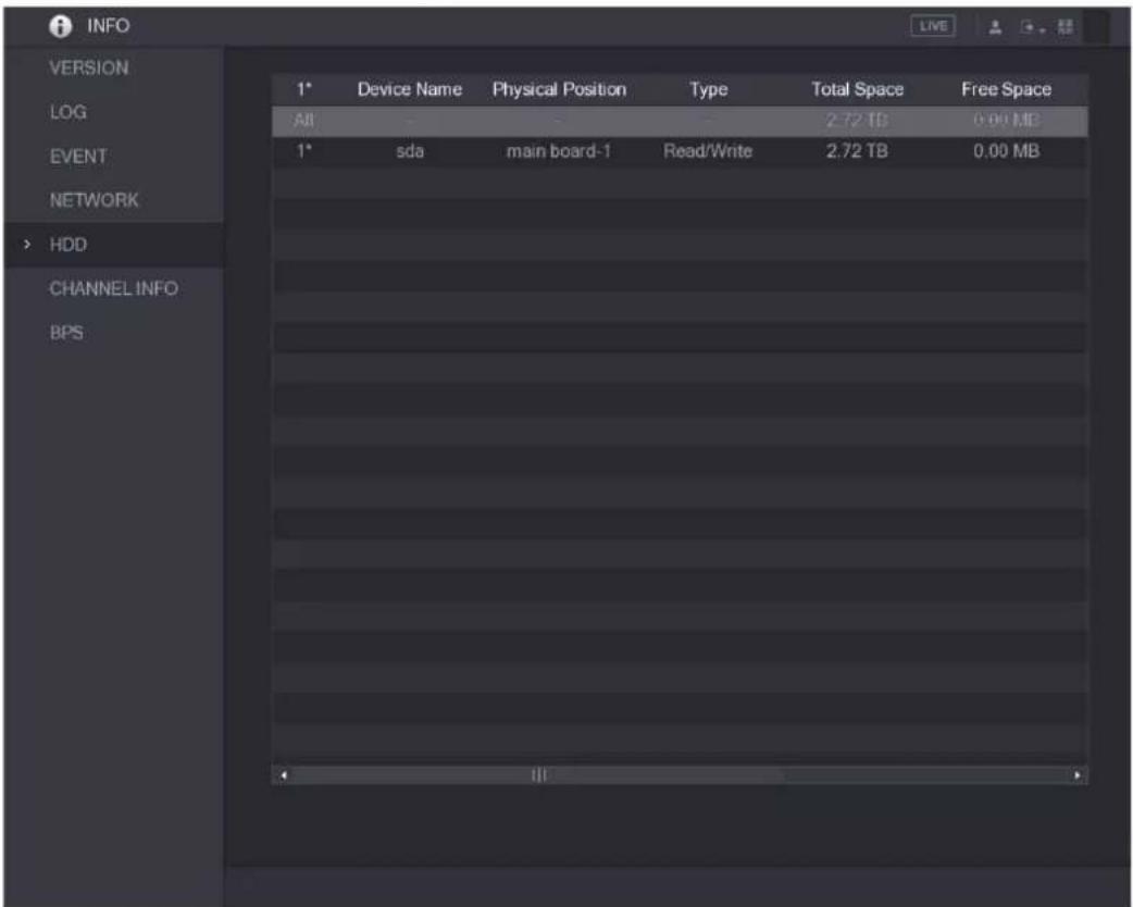
Table 5-72 HDD parameters
| Parameter Description | |
| No. | Indicates the number of the currently connected HDD. The asterisk (*) means the current working HDD. |
| Device Name | Indicates name of HDD. |
| Physical Position | Indicates installation position of HDD. |
| Type Indicates HDD type. | |
| Total Space Indicates the total capacity of HDD. | |
| Free Space | Indicates the usable capacity of HDD. |
| Status | Indicates the status of the HDD to show if it is working normally. |
| S.M.A.R.T | View the S.M.A.R.T reports from HDD detecting. |
5.21.6 Viewing Channel Information
You can view the camera information connected to each channel.
Select Main Menu > INFO > CHANNEL INFO, the CHANNEL INFO page is displayed.
Figure 5-365 Channel information
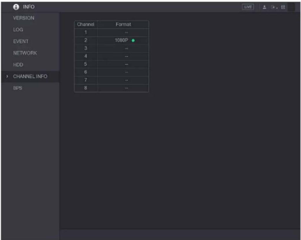
5.21.7 Viewing Data Stream Information
You can view the real-time data stream rate and resolution of each channel. Select Main Menu > INFO > BPS, the BPS page is displayed.
Figure 5-366 BPS
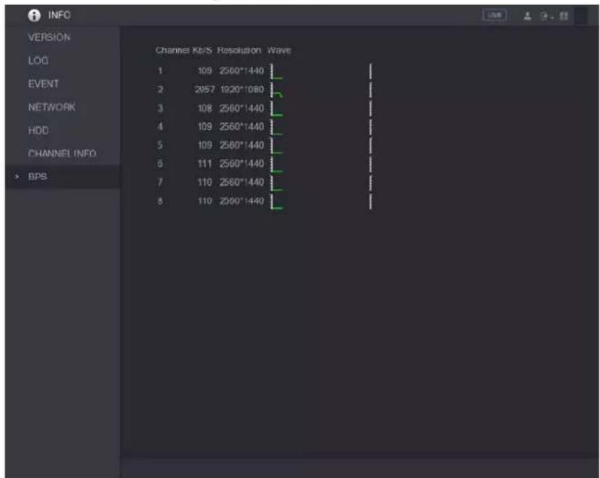
line
| Channel | KPS | Resolution | Wave | | :--- | :--- | :--- | :--- | | 1 | 109 | 2560*1440 | | | 2 | 2057 | 1920*1080 | | | 3 | 108 | 2560*1440 | | | 4 | 109 | 2560*1440 | | | 5 | 109 | 2560*1440 | | | 6 | 111 | 2560*1440 | | | 7 | 110 | 2560*1440 | | | 8 | 110 | 2560*1440 | |5.22 Logging out of the Device
On the upper-right corner of the Main Menu page or on any page after you have entered the Main
Menu, click

- Select Logout, you will log out the device.
- Select Reboot, the Device will be rebooted.
- Select Shutdown, the Device will be turned off.
6 Web Operations

- The pages in the Manual are used for introducing the operations and only for reference. The actual page might be different dependent on the model you purchased. If there is inconsistency between the Manual and the actual product, the actual product shall govern.
- The Manual is a general document for introducing the product, so there might be some functions described for the Device in the Manual not apply to the model you purchased.
- Besides Web, you can use our Smart PSS to log in to the device. For detailed information, refer to Smart PSS user's manual.
6.1 Connecting to Network

● The factory default IP of the Device is 192.168.1.108.
- The Device supports monitoring on different browsers such as Safari, fire fox, Google on Apple PC to perform the functions such as multi-channel monitoring, PTZ control, and device parameters configurations.
Step 1 Check to make sure the Device has connected to the network.
Step 2 Configure the IP address, subnet mask and gateway for the PC and the Device. For details about network configuration of the Device, see "5.1.4.4 Configuring Network Settings".
Step 3 On your PC, check the network connection of the Device by using "ping ***.***.***." Usually the return value of TTL is 255.
6.2 Logging in to the Web
Step 1 Open the IE browser, enter the IP address of the Device, and then press Enter. The Login in dialog box is displayed.
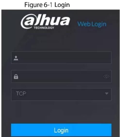
Step 2 Enter the username and password.

- The default administrator account is admin. The password is the one that was configured during initial settings. To security your account, it is recommended to keep the password properly and change it regularly.
- Click to display the password.
Step 3 Click Login.
6.3 Introducing Web Main Menu
After you have logged in the web, the main menu is displayed.
Figure 6-2 Main menu
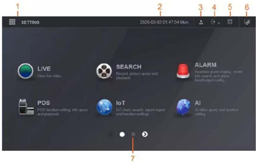
Table 6-1 Main menu description
| No. Icon Description | ||
| 1 |  | Includes configuration menu through which you can configure camera settings, network settings, storage settings, system settings, account settings, and view information. |
| 2 | None | Displays system date and time. |
| 3 |  | When you point to ,the current user account is displayed. |
| 4 |  | Click , select Logout, Reboot, or Shutdown according to your actual situation. |
| 5 |  | Displays Cell Phone Client and Device SN QR Code.Cell Phone Client: Use your mobile phone to scan the QR code to add the device into the Cell Phone Client, and then you can start accessing the Device from your cell phone.Device SN: Obtain the Device SN by scanning the QR code. Go to the P2P management platform and add the Device SN into the platform. Then you can access and manage the device in the WAN. For details, please refer to the P2P operation manual. You can also configure P2P function in the local configurations. See "5.1.4.5 Configuring P2P Settings". |
| 6 |  | Displays the web main menu. |
| 7 None | Includes eight function tiles: LIVE, VIDEO, ALARM, IoT, AI, BACKUP, DISPLAY, and AUDIO. Click each tile to open the configuration page of the tile.LIVE: You can perform the operations such as viewing real-time video, configuring channel layout, setting PTZ controls, and using smart talk and instant record functions if needed.VIDEO: Search for and play back the recorded video saved on the Device.ALARM: Search for alarm information and configure alarm event actions.AI: Configure face detection, face recognition, and IVS functions.IoT: You can view, search and export the temperature and humidity data of camera and configure the alarm event settings.BACKUP: Search and back up the video files to the local PC or external storage device such as USB storage device.DISPLAY: Configure the display effect such as displaying content, image transparency, and resolution, and enable the zero-channel function.AUDIO: Manage audio files and configure the playing schedule. The audio file can be played in response to an alarm event if the voice prompts function is enabled. | |
6.4 Viewing Open-source Software Notice
Log in to the web, select MAINTAIN > System Info > Legal Info, and then click View to view open-source software notice.
Figure 6-3 Legal information
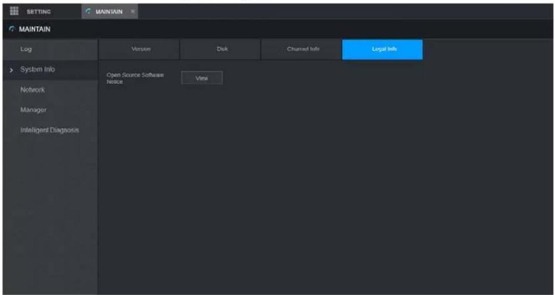
7 FAQ
1. DVR cannot boot up properly.
There are following possibilities:
- Input power is not correct.
● Power connection is not correct.
● Power switch button is damaged.
- Program upgrade is wrong.
- HDD malfunction or something wrong with HDD jumper configuration.
- Seagate DB35.1, DB35.2, SV35 or Maxtor 17-g has compatibility problem. Upgrade to the latest version to solve this problem.
- Front panel error.
- Main board is damaged.
2. DVR frequently shuts down or stops running.
There are following possibilities:
- Input voltage is not stable or it is too low.
- HDD malfunction or something wrong with jumper configuration.
- Button power is not enough.
• Front video signal is not stable. - Working environment is too harsh, too much dust.
- Hardware malfunction.
3. Hard disk cannot be detected.
There are following possibilities:
- HDD is broken.
• HDD jumper is damaged.
• HDD cable connection is loose. - Main board SATA port is broken.
4. There is no video output whether it is one-channel, multiple-channel or all-channel output.
There are following possibilities:
- Program is not compatible. Upgrade to the latest version.
- Brightness is 0. Restore factory default setup.
- There is no video input signal or it is too weak.
- Check privacy mask setup or your screen saver.
• DVR hardware malfunctions.
5. Real-time video color is distorted.
There are following possibilities:
- When using BNC output, NTSC and PAL setup is not correct. The real-time video becomes black and white.
• DVR and monitor resistance is not compatible.
• Video transmission is too long or degrading is too huge.
• DVR color or brightness setup is not correct.
6. Cannot search local records.
There are following possibilities:
• HDD jumper is damaged.
- HDD is broken.
- Upgraded program is not compatible.
• The recorded file has been overwritten.
- Record function has been disabled.
7. Video is distorted when searching local records.
There are following possibilities:
• Video quality setup is too low.
- Program read error, bit data is too small. There is mosaic in the full screen. Restart the DVR to solve this problem.
• HDD data jumper error.
- HDD malfunction.
• DVR hardware malfunctions.
8. No audio under monitor state.
There are following possibilities:
- It is not a power picker.
• It is not a power acoustics.
• Audio cable is damaged.
• DVR hardware malfunctions.
9. There is audio under monitor state but no audio under playback state.
There are following possibilities:
- Setup is not correct. Enable audio function.
- Corresponding channel has no video input. Playback is not continuous when the screen is blue.
10. System time is not correct.
There are following possibilities:
- Setup is not correct.
● Battery contact is not correct or voltage is too low.
• Crystal oscillator is broken.
11. Cannot control PTZ on DVR.
There are following possibilities:
- Front panel PTZ error.
- PTZ decoder setup, connection or installation is not correct.
• Cable connection is not correct. - PTZ setup is not correct.
• PTZ decoder and DVR protocol is not compatible. - PTZ decoder and DVR address is not compatible.
- When there are several decoders, add 120 Ohm between the PTZ decoder A/B cables furthest end to delete the reverberation or impedance matching. Otherwise the PTZ control is not stable.
- The distance is too far.
12. Motion detection function does not work.
There are following possibilities:
• Period setup is not correct.
- Motion detection zone setup is not correct.
- Sensitivity is too low.
- For some versions, there is hardware limit.
13. Cannot log in client-end or web.
There are following possibilities:
- For Windows 98 or Windows ME user, update your system to Windows 2000 sp4. Or you can install client-end software of lower version. Note right now, our DVR is not compatible with Windows VISTA control.
• ActiveX control has been disabled. - No dx8.1 or higher. Upgrade display card driver.
• Network connection error. - Network setup error.
- Password or username is invalid.
- Client-end is not compatible with DVR program.
14. There is only mosaic no video when preview or playback video file remotely.
There are following possibilities:
• Network fluency is not good.
- Client-end resources are limit.
- There is multiple-cast group setup in DVR. This mode can result in mosaic. Usually we do not recommend this mode.
- There is privacy mask or channel protection setup.
- Current user has no right to monitor.
• DVR local video output quality is not good.
15. Network connection is not stable.
There are following possibilities:
- Network is not stable.
- IP address conflict.
- MAC address conflict.
• PC or DVR network card is not good.
16. Burn error /USB back error.
There are following possibilities:
- Burner and DVR are in the same data cable.
- System uses too much CPU resources. Stop record first and then begin backup.
● Data amount exceeds backup device capacity. It might result in burner error. - Backup device is not compatible.
- Backup device is damaged.
17. Keyboard cannot control DVR
There are following possibilities:
• DVR serial port setup is not correct.
- Address is not correct.
- When there are several switchers, power supply is not enough.
• Transmission distance is too far.
18. Alarm signal cannot be disarmed.
There are following possibilities:
-
Alarm setup is not correct.
• Alarm output has been open manually. -
Input device error or connection is not correct.
- Some program versions might have this problem. Upgrade your system.
19. Alarm function is null.
There are following possibilities:
- Alarm setup is not correct.
- Alarm cable connection is not correct.
• Alarm input signal is not correct.
● There are two loops connect to one alarm device.
20. Remote control does not work.
There are following possibilities:
- Remote control address is not correct.
- Distance is too far or control angle is too small.
- Remote control battery power is low.
- Remote control is damaged or DVR front panel is damaged.
21. Record storage period is not enough.
There are following possibilities:
- Camera quality is too low. Lens is dirty. Camera is installed against the light. Camera aperture setup is not correct.
• HDD capacity is not enough. - HDD is damaged.
22. Cannot playback the downloaded file.
There are following possibilities:
- There is no media player.
- No DXB8.1 or higher graphic acceleration software.
- There is no DivX503Bundle.exe control when you play the file transformed to AVI via media player.
- No DivX503Bundle.exe or ffdshow-2004 1012 .exe in Windows XP OS.
23. Forgot local menu operation password or network password
Contact your local service engineer or our sales person for help. We can guide you to solve this problem.
24. When I login via HTTPS, a dialogue says the certificate for this website is for other address.
Create server certificate again.
25. When I login via HTTPS, a dialogue says the certificate is not trusted.
Download root certificate again.
26. When I login via HTTPS, a dialogue says the certificate has expired or is not valid yet.
Make sure your PC time is the same as the device time.
27. I connect the general analog camera to the device, there is no video output.
There are following possibilities:
- Check camera power supplying, data cable connection and other items.
- This series device does not support the analog camera of all brands. Make sure the device supports general standard definition analog camera.
28. I connect the standard definition analog camera or the coaxial camera to the device, there is no video output.
There are following possibilities:
- Check camera power supplying, or camera data cable connection.
- For the product supports analog standard definition camera/HD camera, you need to go to the Main Menu > CAMERA > CHANNEL TYPE to select corresponding channel type and then restart the DVR.
29. I cannot connect to the IP channel.
There are following possibilities:
- Check the camera is online or not.
- Check IP channel setup is right or not (such as IP address, username, password, connection protocol, and port number).
● The camera has set the allowlist (Only the specified devices can connect to the camera).
30. After I connected to the IP channel, the one-window output is OK, but there is no multiple-window output.
There are following possibilities:
- Check the sub stream of the camera has been enabled or not.
- Check the sub stream type of the camera is H.264 or not.
- Check the device supports camera sub stream resolution or not (such as 960H, D1, and HD1).
31. After I connected to the IP channel, the multiple-window output is OK, but there is no one-window output.
There are following possibilities:
- Check there is video from the IP channel or not. Go to the Main Menu > INFO > BPS to view bit stream real-time information.
- Check the main stream of the camera has been enabled or not.
- Check the main stream type of the camera is H.264 or not.
- Check the device supports camera main stream resolution or not (such as 960H, D1, and HD1).
- Check camera network transmission has reached the threshold or not. Check the online user of the camera.
32. After I connected to the IP channel, there is no video output in the one-window or the multiple-window mode. But I can see there is bit stream.
There are following possibilities:
- Check the main stream/sub stream type of the camera is H.264 or not.
- Check the device supports camera main stream/sub stream resolution or not (such as 1080P, 720P, 960H, D1, and HD1).
- Check the camera setup. Make sure It supports the products of other manufacturers.
33. DDNS registration failed or cannot access the device domain name.
There are following possibilities:
- Check the device is connected to the WAN. Check the device has got the IP address if the PPPoE can dial. If there is a router, check the router to make sure the device IP is online.
- Check the corresponding protocol of the DDNS is enabled. Check the DDNS function is OK or not.
- Check DNS setup is right or not. Default Google DNS server is 8.8.8.8, 8.8.5.5. You can use different DNS provided by your ISP.
34. I cannot use the P2P function on my cell phone or the web.
There are following possibilities:
- Check the device P2P function is enabled or not. (Main menu->Setting->Network->P2P)
- Check the device is in the WAN or not.
-
Check cell phone P2P login mode is right or not.
-
It is the specified device P2P login port or not when you are using P2P client.
- Check username or password is right or not.
- Check P2P SN is right or not. You can use the cell phone to scan the QR code on the device P2P page (Main Menu > Network > P2P), or you can use the version information of the WEB to confirm. (For some previous series products, the device SN is the main board SN, it might result in error.)
35. I connect the standard definition camera to the device, there is no video output.
There are following possibilities:
- Check the DVR supports standard definition signal or not. Only some series product supports analog standard definition signal, coaxial signal input.
- Check channel type is right or not. For the product supports analog standard definition camera/HD camera, you need to go to the Main Menu > CAMERA > CHANNEL TYPE to select corresponding channel type (such as analog) and then restart the DVR. In this way, the DVR can recognize the analog standard definition.
- Check camera power supplying, or camera data cable connection.
36. I cannot connect to the IP camera.
There are following possibilities:
- Check DVR supports IP channel or not. Only some series products support A/D switch function, it can switch analog channel to the IP channel to connect to the IP camera. From Main Menu > CAMERA > CHANNEL TYPE, select the last channel to switch to the IP channel. Some series product products support IP channel extension, it supports N+N mode.
- Check the IPC and the DVR is connected or not. Go to the Main Menu > CAMERA > REGISTRATION to search to view the IP camera is online or not. Or you can go to the Main Menu > INFO > NETWORK > Network Test, you can input IP camera IP address and then click the Test button to check you can connect to the IP camera or not.
- Check IP channel setup is right or not (such as IP address, manufacturer, port, username, password, and remote channel number).
Daily Maintenance
- Use the brush to clean the board, socket connector and the chassis regularly.
- The device shall be soundly earthed in case there is audio/video disturbance. Keep the device away from the static voltage or induced voltage.
● Unplug the power cable before you remove the audio/video signal cable, RS-232 or RS-485 cable. - Do not connect the TV to the local video output port (VOUT). It might result in video output circuit.
- Always shut down the device properly. Use the shutdown function in the menu, or you can press the power button in the front panel for at least three seconds to shut down the device. Otherwise it might result in HDD malfunction.
- Make sure the device is away from the direct sunlight or other heating sources. Keep the sound ventilation.
- Check and maintain the device regularly.
Appendix 1 Glossary
The abbreviations in this glossary are related to the Manual.
Appendix Table 1-1 Glossary
| Abbreviations Full term | |
| BNC Bayonet Nut Connector | |
| CBR Constant Bit Rate | |
| CIF Common Intermediate Format | |
| DDNS Dynamic Domain Name Service | |
| DHCP | Dynamic Host Configuration Protocol |
| DNS Domain Name System | |
| DST Daylight Saving Time | |
| DVR | Digital Video Recorder |
| FTP File Transfer Protocol | |
| HDD Hard Disk Drive | |
| HDMI | High Definition Multimedia Interface |
| HTTP | Hyper Text Transfer Protocol |
| IoT | Internet of Things |
| IP | Internet Protocol |
| IVS Intelligent Video System | |
| LAN | Local Area Network |
| MAC | Media Access Control |
| MTU | Maximum Transmission Unit |
| NTP | Network Time Protocol |
| NTSC | National Television Standards Committee |
| ONVIF | Open Network Video Interface Forum |
| PAL | Phase Alteration Line |
| PAT | Port Address Translation |
| POS | Point of Sale |
| PPPoE | Point-to-Point Protocol over Ethernet |
| PSS | Professional Surveillance Software |
| PTZ | Pan Tilt Zoom |
| RCA | Radio Corporation of American |
| RTSP | Real Time Streaming Protocol |
| S.M.A.R.T | Self-Monitoring-Analysis and Reporting Technology |
| SATA | Serial Advanced Technology Attachment |
| SMTP | Simple Mail Transfer Protocol |
| SNMP | Simple Network Management Protocol |
| TCP | Transmission Control Protocol |
| TFTP | Trivial File Transfer Protocol |
| UDP User Datagram Protocol | |
| UPnP Universal Plug and Play | |
| VBR Variable Bit Rate | |
| VGA Video Graphics Array | |
| WAN Wide Area Network | |
Appendix 2 HDD Capacity Calculation
Calculate total capacity needed by each DVR according to video recording (video recording type and video file storage time).
Step 1 According to Formula (1) to calculate storage capacity q_i that is the capacity of each channel needed for each hour, unit MB.
$$ \text { Formula } (1): q _ {i} \quad d _ {i} \quad 8 \div x \div = 1 0 2 4 $$
In the formula: d_i means the bit rate, unit Kbit/s
Step 2 After video time requirement is confirmed, according to Formula (2) to calculate the storage capacity m_i , which is storage of each channel needed unit MB.
$$ \text { Formula (2): } m _ {i} = q _ {i} \times h _ {i} \times D _ {i} $$
In the formula:
- h_i means the recording time for each day (hour)
- D_i means number of days for which the video shall be kept
Step 3 According to Formula (3) to calculate total capacity (accumulation) q_T that is needed for all channels in the DVR during scheduled video recording.
$$ \text { Formula (3): } \quad q _ {T} = \sum_ {i = 1} ^ {c} m _ {i} $$
In the formula: c means total number of channels in one DVR
Step 4 According to Formula (4) to calculate total capacity (accumulation) q_T that is needed for all channels in DVR during alarm video recording (including motion detection).
$$ \text { Formula } (4): q _ {T} = \sum_ {i = 1} ^ {c} m _ {i} \times a \% $$
In the formula: a% means alarm occurrence rate
You can refer to the following table for the file size in one hour per channel. (All the data listed below are for reference only.)
Appendix Table 2-1 HDD capacity calculation
| Bit Stream Size (max) | File Size | Bit Stream Size (max) | File Size |
| 96 Kbps | 42 MB | 128 Kbps | 56 MB |
| 160 Kbps | 70 MB | 192 Kbps | 84 MB |
| 224 Kbps | 98 MB | 256 Kbps | 112 MB |
| 320 Kbps | 140 MB | 384 Kbps | 168 MB |
| 448 Kbps | 196 MB | 512 Kbps | 225 MB |
| 640 Kbps | 281 MB | 768 Kbps | 337 MB |
| 896 Kbps | 393 MB | 1024 Kbps | 450 MB |
| 1280 Kbps | 562 MB | 1536 Kbps | 675 MB |
| 1792 Kbps | 787 MB | 2048 Kbps | 900 MB |
Appendix 3 Compatible Backup Devices
Appendix 3.1 Compatible USB List
Appendix Table 3-1 Compatible USB
| Manufacturer | Model | Capacity |
| Sandisk | Cruzer Micro | 512 MB |
| Sandisk Cruzer Micro 1 GB | ||
| Sandisk Cruzer Micro 2 GB | ||
| Sandisk | Cruzer Freedom | 256 MB |
| Sandisk | Cruzer Freedom | 512 MB |
| Sandisk | Cruzer Freedom | 1 GB |
| Sandisk | Cruzer Freedom | 2 GB |
| Kingston | DataTraveler II | 1 GB |
| Kingston | DataTraveler II | 2 GB |
| Kingston | DataTraveler | 1 GB |
| Kingston | DataTraveler | 2 GB |
| Maxell | USB Flash Stick | 128 MB |
| Maxell | USB Flash Stick | 256 MB |
| Maxell | USB Flash Stick | 512 MB |
| Maxell USB Flash Stick 1 GB | ||
| Maxell USB Flash Stick 2 GB | ||
| Kingax | Super Stick | 128 MB |
| Kingax | Super Stick | 256 MB |
| Kingax | Super Stick | 512 MB |
| Kingax | Super Stick | 1 GB |
| Kingax | Super Stick | 2 GB |
| Netac | U210 | 128 MB |
| Netac | U210 | 256 MB |
| Netac | U210 | 512 MB |
| Netac | U210 | 1 GB |
| Netac | U210 | 2 GB |
| Netac | U208 | 4 GB |
| Teclast | Ti Cool | 128 MB |
| Teclast | Ti Cool | 256 MB |
| Teclast | Ti Cool | 512 MB |
| Teclast | Ti Cool | 1 GB |
| Sandisk Cruzer Micro 2 GB | ||
| Sandisk Cruzer Micro 8 GB | ||
| Sandisk | Ti Cool | 2 GB |
| Sandisk Hongjiao 4 GB | ||
| Lexar | Lexar | 256 MB |
| Kingston | Data Traveler | 1 GB |
| Kingston | Data Traveler | 16 GB |
| Kingston | Data Traveler | 32 GB |
| Aigo | L8315 | 16 GB |
| Sandisk | 250 | 16 GB |
| Kingston | Data Traveler Locker+ | 32 GB |
| Netac | U228 | 8 GB |
Appendix 3.2 Compatible SD Card List
Appendix Table 3-2 Compatible SD card
| Manufacturer | Standard | Capacity | Card type |
| Transcend | SDHC6 | 16 GB | Big |
| Kingston | SDHC4 | 4 GB | Big |
| Kingston | SD | 2 GB | Big |
| Kingston | SD | 1 GB | Big |
| Sandisk | SDHC2 | 8 GB | Small |
| Sandisk | SD | 1 GB | Small |
Appendix 3.3 Compatible Portable HDD List
Appendix Table 3-3 Compatible portable HDD
| Manufacturer | Model | Capacity |
| YDStar | YDstar HDD box | 40 GB |
| Netac | Netac | 80 GB |
| Iomega | Iomega RPHD-CG" RNAJ50U287 | 250 GB |
| WD Elements | WCAVY1205901 | 1.5 TB |
| Newsmy | Liangjian | 320 GB |
| WD Elements | WDBAAR5000ABK-00 | 500 GB |
| WD Elements | WDBAAU0015HBK-00 | 1.5 TB |
| Seagate | FreeAgent Go(ST905003F) | 500 GB |
| Aigo | H8169 | 500 GB |
Appendix 3.4 Compatible USB DVD List
Appendix Table 3-4 Compatible USB DVD
| Manufacturer Model | |
| Samsung SE-S084 | |
| BenQ LD2000-2K4 |
Appendix 3.5 Compatible SATA DVD List
| Manufacturer Model | |
| LG GH22NS30 | |
| Samsung | TS-H653 Ver.A |
| Samsung | TS-H653 Ver.F |
| Samsung | SH-224BB/CHXH |
| SONY DRU-V200S | |
| SONY DRU-845S | |
| SONY AW-G170S | |
| Pioneer DVR-217CH |
Appendix 3.6 Compatible SATA HDD List

Upgrade the DVR firmware to latest version to ensure the accuracy of the table below. Here we recommend HDD of 500 GB to 4 TB capacity.
Appendix Table 3-5 Compatible SATA HDD
| Manufacturer | Series | Model | Capacity | Port Mode |
| Seagate | Video 3.5 | ST1000VM002 | 1 TB | SATA |
| Seagate | Video 3.5 | ST2000VM003 | 2 TB | SATA |
| Seagate | Video 3.5 | ST3000VM002 | 3 TB | SATA |
| Seagate | Video 3.5 | ST4000VM000 | 4 TB | SATA |
| Seagate | SV35 | ST1000VX000 | 1 TB | SATA |
| Seagate | SV35 | ST2000VX000 | 2 TB | SATA |
| Seagate | SV35 | ST3000VX000 | 3 TB | SATA |
| Seagate | SV35 (Support HDD data recovery offered by Seagate) | ST1000VX002 | 1 TB | SATA |
| Seagate | SV35 (Support HDD data recovery offered by Seagate) | ST2000VX004 | 2 TB | SATA |
| Seagate | SV35 (Support HDD data recovery offered by Seagate) | ST3000VX004 | 3 TB | SATA |
| Seagate | SkyHawk HDD | ST1000VX001 | 1 TB | SATA |
| Seagate | SkyHawk HDD | ST1000VX005 | 1 TB | SATA |
| Seagate | SkyHawk HDD | ST2000VX003 | 2 TB | SATA |
| Seagate | SkyHawk HDD | ST2000VX008 | 2 TB | SATA |
| Seagate | SkyHawk HDD | ST3000VX006 | 3 TB | SATA |
| Seagate | SkyHawk HDD | ST3000VX010 | 3 TB | SATA |
| Seagate | SkyHawk HDD | ST4000VX000 | 4 TB | SATA |
| Seagate | SkyHawk HDD | ST4000VX007 | 4 TB | SATA |
| Seagate | SkyHawk HDD | ST5000VX0001 | 5 TB | SATA |
| Seagate | SkyHawk HDD | ST6000VX0001 | 6 TB | SATA |
| Seagate | SkyHawk HDD | ST6000VX0023 | 6 TB | SATA |
| Seagate | SkyHawk HDD | ST6000VX0003 | 6 TB | SATA |
| Seagate | SkyHawk HDD | ST8000VX0002 | 8 TB | SATA |
| Seagate | SkyHawk HDD | ST8000VX0022 | 8 TB | SATA |
| Seagate | SkyHawk HDD | ST100000VX0004 | 10 TB | SATA |
| Seagate SkyHawk | HDD (Support HDD data recovery offered by Seagate) | ST1000VX003 1 TB SATA | ||
| Seagate | SkyHawk HDD (Support HDD data recovery offered by Seagate) | ST2000VX005 2 TB SATA | ||
| Seagate | SkyHawk HDD (Support HDD data recovery offered by Seagate) | ST3000VX005 3 TB SATA | ||
| Seagate | SkyHawk HDD (Support HDD data recovery offered by Seagate) | ST4000VX002 4 TB SATA | ||
| Seagate SkyHawk | HDD (Support HDD data recovery offered by Seagate) | ST5000VX0011 5 TB SATA | ||
| Seagate SkyHawk | HDD (Support HDD data recovery offered by Seagate) | ST6000VX0011 6 TB SATA | ||
| Seagate SkyHawk | HDD (Support HDD data recovery offered by Seagate) | ST8000VX0012 8 TB SATA | ||
| WD | WD Green | WD10EURX (EOL) | 1 TB | SATA |
| WD | WD Green | WD20EURX (EOL) | 2 TB | SATA |
| WD | WD Green | WD30EURX (EOL) | 3 TB | SATA |
| WD | WD Green | WD40EURX (EOL) | 4 TB | SATA |
| WD | WD Purple | WD10PURX | 1 TB | SATA |
| WD | WD Purple | WD20PURX | 2 TB | SATA |
| WD | WD Purple | WD30PURX | 3 TB | SATA |
| WD | WD Purple | WD40PURX | 4 TB | SATA |
| WD | WD Purple | WD50PURX | 5 TB | SATA |
| WD | WD Purple | WD60PURX | 6 TB | SATA |
| WD | WD Purple | WD80PUZX | 8 TB | SATA |
| WD | WD Purple | WD10PURZ | 1 TB | SATA |
| WD | WD Purple | WD20PURZ | 2 TB | SATA |
| WD | WD Purple | WD30PURZ | 3 TB | SATA |
| WD | WD Purple | WD40PURZ | 4 TB | SATA |
| WD | WD Purple | WD50PURZ | 5 TB | SATA |
| WD | WD Purple | WD60PURZ | 6 TB | SATA |
| WD | WD Purple | WD80PURZ | 8 TB | SATA |
| WD | WD Purple | WD4NPURX | 4 TB | SATA |
| WD | WD Purple | WD6NPURX | 6 TB | SATA |
| TOSHIBA | Mars | DT01ABA100V | 1 TB | SATA |
| TOSHIBA | Mars | DT01ABA200V | 2 TB | SATA |
| TOSHIBA | Mars | DT01ABA300V | 3 TB | SATA |
| TOSHIBA | Sonance | MD03ACA200V | 2 TB | SATA |
| TOSHIBA | Sonance | MD03ACA300V | 3 TB | SATA |
| TOSHIBA | Sonance | MD03ACA400V | 4 TB | SATA |
| TOSHIBA | Sonance | MD04ABA400V | 4 TB | SATA |
| TOSHIBA | Sonance | MD04ABA500V | 5 TB | SATA |
| Seagate | Constellation ES series (SATA interface) | ST1000NM0033 | 1 TB | SATA |
| Seagate | Constellation ES series (SATA interface) | ST2000NM0033 | 2 TB | SATA |
| Seagate | Constellation ES series (SATA interface) | ST3000NM0033 | 3 TB | SATA |
| Seagate | Constellation ES series (SATA interface) | ST4000NM0033 | 4 TB | SATA |
| Seagate | Constellation ES series (SATA interface) | ST1000NM0055 | 1 TB | SATA |
| Seagate | Constellation ES series (SATA interface) | ST2000NM0055 | 2 TB | SATA |
| Seagate | Constellation ES series (SATA interface) | ST3000NM0005 | 3 TB | SATA |
| Seagate | Constellation ES series (SATA interface) | ST4000NM0035 | 4 TB | SATA |
| Seagate | Constellation ES series (SATA interface) | ST6000NM0115 | 6 TB | SATA |
| Seagate | Constellation ES series (SATA interface) | ST8000NM0055 | 8 TB | SATA |
| Seagate | Constellation ES series (SATA interface) | ST10000NM0016 | 10 TB | SATA |
| Seagate | Constellation ES series (SATA interface) | ST4000NM0024 4 TB SATA | ||
| Seagate | Constellation ES series (SATA interface) | ST6000NM0024 6 TB SATA | ||
| Seagate Constellation ES series (SAS interface) | ST1000NM0023 | 1 TB | SATA | |
| Seagate | Constellation ES series (SAS interface) | ST2000NM0023 2 TB SATA | ||
| Seagate | Constellation ES series (SAS interface) | ST3000NM0023 3 TB SATA | ||
| Seagate | Constellation ES series (SAS interface) | ST4000NM0023 4 TB SATA | ||
| Seagate Constellation ES series (SAS interface) | ST6000NM0014 6 TB SATA | |||
| Seagate | Constellation ES series (SAS interface) | ST1000NM0045 1 TB SATA | ||
| Seagate | Constellation ES series (SAS interface) | ST2000NM0045 2 TB SATA | ||
| Seagate | Constellation ES series (SAS interface) | ST3000NM0025 3 TB SATA | ||
| Seagate | Constellation ES series (SAS interface) | ST4000NM0025 4 TB SATA | ||
| Seagate | Constellation ES series (SAS interface) | ST6000NM0095 6 TB SATA | ||
| Seagate | Constellation ES series (SAS interface) | ST6000NM0034 6 TB SATA | ||
| Seagate Constellation ES series (SAS interface) | ST8000NM0075 8 TB SATA | |||
| WD WD RE series (SATA interface) | WD1003FBYZ 1 TB SATA | |||
| WD | WD RE series (SATA interface) | WD1004FBYZ (replace WD1003FBYZ) | 1 TB SATA | |
| WD | WD RE series (SATA interface) | WD2000FYYZ 2 TB SATA | ||
| WD | WD RE series (SATA interface) | WD2004FBYZ (replace WD2000FYYZ) | 2 TB SATA | |
| WD | WD RE series (SATA interface) | WD3000FYYZ 3 TB SATA | ||
| WD | WD RE series (SATA interface) | WD4000FYYZ 4 TB SATA | ||
| WD | WD (SATA interface) | WD2000F9YZ | 2 TB | SATA |
| WD | WD (SATA interface) | WD3000F9YZ | 3 TB | SATA |
| WD | WD (SATA interface) | WD4000F9YZ | 4 TB | SATA |
| WD | WD (SATA interface) | WD4002FYYZ | 4 TB | SATA |
| WD | WD (SATA interface) | WD6001FSYZ | 6 TB | SATA |
| WD | WD (SATA interface) | WD6002FRYZ | 6 TB | SATA |
| WD | WD (SATA interface) | WD8002FRYZ | 8 TB | SATA |
| HITACHI | Ultrastar series (SATA interface) | HUS724030ALA640 | 3 TB | SATA |
| HITACHI | Ultrastar series (SATA interface) | HUS726060ALE610 | 6 TB | SATA |
| HITACHI | Ultrastar series (SATA interface) | HUH728060ALE600 | 6 TB | SATA |
| HITACHI | Ultrastar series (SATA interface) | HUH728080ALE600 | 8 TB | SATA |
| HITACHI | Ultrastar series (SAS interface) | HUS726020AL5210 | 2 TB | SATA |
| HITACHI | Ultrastar series (SAS interface) | HUS726040AL5210 | 4 TB | SATA |
| HITACHI | Ultrastar series (SAS interface) | HUS726060AL5210 | 6 TB | SATA |
| Seagate | Pipeline HD Mini | ST320VT000 | 320 GB | SATA |
| Seagate | Pipeline HD Mini | ST500VT000 | 500 GB | SATA |
| Seagate | Pipeline HD Mini | ST2000LM003 (EOL) | 2 TB | SATA |
| TOSHIBA | 2.5-inch PC series | MQ01ABD050V | 500 GB | SATA |
| TOSHIBA | 2.5-inch PC series | MQ01ABD100V | 1 TB | SATA |
| SAMSUNG | HN-M101MBB | HN-M101MBB (EOL) | 1 TB | SATA |
| Seagate | 2.5-inch enterprise series | ST1000NX0313 | 1 TB | SATA |
| Seagate | 2.5-inch enterprise series | ST2000NX0253 | 2 TB | SATA |
Appendix 4 Compatible CD/DVD Burner List

Upgrade the DVR firmware to latest version to ensure the accuracy of the table below. And you can use the USB cable with the model recommended to set USB burner.
Appendix Table 4-1 Compatible CD/DVD burner
| Manufacturer | Model | Port Type | Type |
| Sony | DRX-S50U | USB | DVD-RW |
| Sony | DRX-S70U | USB | DVD-RW |
| Sony | AW-G170S | SATA | DVD-RW |
| Samsung | TS-H653A | SATA | DVD-RW |
| Panasonic | SW-9588-C | SATA | DVD-RW |
| Sony | DRX-S50U | USB | DVD-RW |
| BenQ | 5232WI | USB | DVD-RW |
Appendix 5 Compatible Displayer List
Refer to the following table form compatible displayer list.
Appendix Table 5-1 Compatible displayer
| Brand | Model | Dimension (Unit: inch) |
| BENQ (LCD) | ET-0007-TA | 19-inch (wide screen) |
| DELL (LCD) | E178FPc | 17-inch |
| BENQ (LCD) | Q7T4 | 17-inch |
| BENQ (LCD) | Q7T3 | 17-inch |
| HFNOVO (LCD) | LXB-L17C | 17-inch |
| SANGSUNG (LCD) | 225BW | 22-inch (wide screen) |
| HFNOVO (CRT) | LXB-FD17069HB | 17-inch |
| HFNOVO (CRT) | LXB-HF769A | 17-inch |
| HFNOVO(CRT) | LX-GJ556D | 17-inch |
| Samsung (LCD) | 2494HS | 24-inch |
| Samsung (LCD) | P2350 | 23-inch |
| Samsung (LCD) | P2250 | 22-inch |
| Samsung (LCD) | P2370G | 23-inch |
| Samsung (LCD) | 2043 | 20-inch |
| Samsung (LCD) | 2243EW | 22-inch |
| Samsung (LCD) | SMT-1922P | 19-inch |
| Samsung (LCD) | T190 | 19-inch |
| Samsung (LCD) | T240 | 24-inch |
| LG (LCD) | W1942SP | 19-inch |
| LG (LCD) | W2243S | 22-inch |
| LG (LCD) | W2343T | 23-inch |
| BENQ (LCD) | G900HD | 18.5-inch |
| BENQ (LCD) | G2220HD | 22-inch |
| PHILIPS (LCD) | 230E | 23-inch |
| PHILIPS (LCD) | 220CW9 | 23-inch |
| PHILIPS (LCD) | 220BW9 | 24-inch |
| PHILIPS (LCD) | 220EW9 | 25-inch |
Appendix 6 Compatible Switcher
Appendix Table 6-1 Compatible switcher
| Brand | Model | network working mode |
| D-LinK | DES-1016D | 10/100M self-adaptive |
| D-LinK | DES-1008D | 10/100M self-adaptive |
| Ruijie RG-S1926S | Five network modes:● AUTO● HALF-10M● FULL-10M● HALF-100M● FULL-100M | |
| H3C | H3C-S1024 | 10/100M self-adaptive |
| TP-LINK | TL-SF1016 | 10/100M self-adaptive |
| TP-LINK | TL-SF1008+ | 10/100M self-adaptive |
Appendix 7 Earthing
Appendix 7.1 What is the Surge
Surge is a short current or voltage change during a very short time. In the circuit, it lasts for microsecond. In a 220 V circuit, the 5KV or 10KV voltage change during a very short time (about microseconds) can be called a surge. The surge comes from two ways: external surge and internal surge.
- The external surge: The external surge mainly comes from the thunder lightning. Or it comes from the voltage change during the on/off operation in the electric power cable.
- The internal surge: The research finds 88% of the surge from the low voltage comes from the internal of the building such as the air conditioning, elevator, electric welding, air compressor, water pump, power button, duplicating machine and other device of inductive load.
The lightning surge is far above the load level the PC or the micro devices can support. In most cases, the surge can result in electric device chip damage, PC error code, accelerating the part aging, data loss and etc. Even when a small 20 horsepower inductive engine boots up or stops, the surge can reach 3000 V to 5000 V, which can adversely affect the electronic devices that use the same distribution box.
To protect the device, you need to evaluate its environment, the lightning affection degree objectively. Because surge has close relationship with the voltage amplitude, frequency, network structure, device voltage-resistance, protection level, ground and etc. The thunder proof work shall be a systematic project, emphasizing the all-round protection (including building, transmission cable, device, ground and etc.). There shall be comprehensive management and the measures shall be scientific, reliable, practical and economic. Considering the high voltage during the inductive thundering, the International Electrotechnical Commission (IEC) standard on the energy absorbing step by step theory and magnitude classification in the protection zone, you need to prepare multiple precaution levels.
You can use the lightning rod, lightning strap or the lightning net to reduce the damage to the building, personal injury or the property.
The lightning protection device can be divided into three types:
- Power lightning arrester: There are 220 V single-phrase lightning arrester and 380 V three-phrase lightning arrester (mainly in parallel connection, sometimes use series connection) You can parallel connect the power lightning arrester in the electric cable to reduce the short-time voltage change and release the surge current. From the BUS to the device, there are usually three levels so that system can reduce the voltage and release the current step by step to remove the thunderstorm energy and guarantee the device safety. You can select the replaceable module type, the terminal connection type and portable socket according to your requirement.
- Signal lightning arrester: This device is mainly used in the PC network, communication system. The connection type is serial connection. Once you connected the signal lightning arrestor with the signal port, it can cut the channel of the thunderstorm to the device, and on the other hand, it can discharge the current to the ground to guarantee the device proper work. The signal lightning arrester has many specifications, and widely used in many devices such as telephone, network, analog communication, digital communication, cable TV and satellite antenna. For all the input port, especially those from the outdoor, you need to install the signal lightning arrester.
- Antenna feed cable lightning arrester: It is suitable for antenna system of the transmitter or the device system to receive the wireless signal. It uses the serial connection too.
Note, when you select the lightning arrester, pay attention to the port type and the earthing reliability. In some important environment, you need to use special shielded cable. Do not parallel connect the thunder proof ground cable with the ground cable of the lightning rod. Make sure they are far enough and grounded respectively.
Appendix 7.2 The Earthing Modes
We all know the earthing is the most complicated technology in the electromagnetism compatibility design since there is no systematic theory or module. The earthing has many modes, but the selection depends on the system structure and performance.
The following are some successfully experience from our past work.
- One-point ground: In the following figure you can see there is a one-point ground. This connection provides common point to allow signal to be transmitted in many circuits. If there is no common point, the error signal transmission occurred. In the one-point ground mode, each circuit is just grounded only and they are connected at the same point. Since there is only one common point, there is no circuit and so, there is no interference.
Appendix Figure 7-1 One-point ground
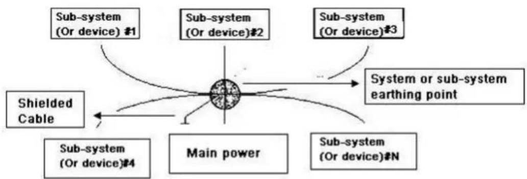
flowchart
graph TD
    A["Shielded Cable"] --> B["Main power"]
    C["Sub-system (Or device) #1"] --> D["Sub-system (Or device) #2"]
    E["Sub-system (Or device) #3"] --> F["Sub-system (Or device) #4"]
    G["Sub-system (Or device) #N"] --> H["Sub-system (Or device) #N"]
    I["System or sub-system earthing point"] --> D
    I --> F
    I --> H
- Multiple-point ground: In the following figure, you can see the internal circuit uses the chassis as the common point. While at the same time, all devices chassis use the earthing as the common point. In this connection, the ground structure can provide the lower ground resistance because when there are multiple-point grounds; each ground cable is as short as possible. And the parallel cable connection can reduce the total conductance of the ground conductor. In the high-frequency circuit, you need to use the multiple-point ground mode and each cable needs to connect to the ground. The length shall be less than the 1/20 of the signal wavelength.
Appendix Figure 7-2 Multiple-point ground
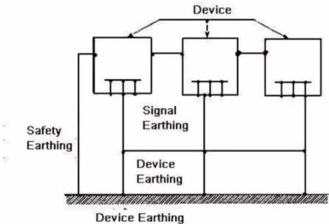
flowchart
graph TD
    A["Device"] --> B["Signal Earthing"]
    A --> C["Device Earthing"]
    B --> D["Device Earthing"]
    C --> D
    style A fill:#f9f,stroke:#333
    style B fill:#ccf,stroke:#333
    style C fill:#ccf,stroke:#333
    style D fill:#dfd,stroke:#333
- Mixed ground: The mix ground consists of the feature of the one-point ground and multiple-point ground. For example, the power in the system needs to use the one-point ground mode while the radio frequency signal requires the multiple-point ground. So, you can use the following figure to earth. For the direct current (DC), the capacitance is open circuit and the circuit is one-point ground. For the radio frequency signal, the capacitance is conducive and the circuit adopts multiple-point ground.
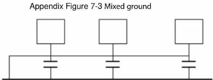
When connecting devices of huge size (the device physical dimension and connection cable is big comparing with the wave path of existed interference), then there is possibility of interference when the current goes through the chassis and cable. In this situation, the interference circuit path usually lies in the system ground circuit.
When considering the earthing, you need to think about two aspects: One is the system compatibility, and the other is the external interference coupling into the earth circuit, which results in system error. For the external interference is not regular, it is not easy to resolve.
Appendix 7.3 Thunder Proof Ground Method in the Monitor System
- The monitor system shall have sound thunder proof earthing to guarantee personnel safety and device safety.
• The monitor system working ground resistance shall be less than 1 Ω.
- The thunder proof ground shall adopt the special ground cable from the monitor control room to the ground object. The ground cable adopts copper insulation cable or wire and its ground
section shall be more than 20mm ^4 .
- The ground cable of the monitor system cannot short circuit or mixed connected with the strong alternative current cable.
- For all the ground cables from the control room to the monitor system or ground cable of other monitor devices, use the copper resistance soft cable and its section shall be more than 4 mm ^2 .
● The monitor system usually can adopt the one-point ground. - Connect the ground end of 3-pin socket in the monitor system to the ground port of the system (protection ground cable)
Appendix 7.4 The Shortcut Way to Check the Electric System by Digital Multimeter
For 220 VAC socket, from the top to the bottom, E (ground cable), N (neutral cable), L (live cable). Refer to the following figure.
Appendix Figure 7-4 Socket
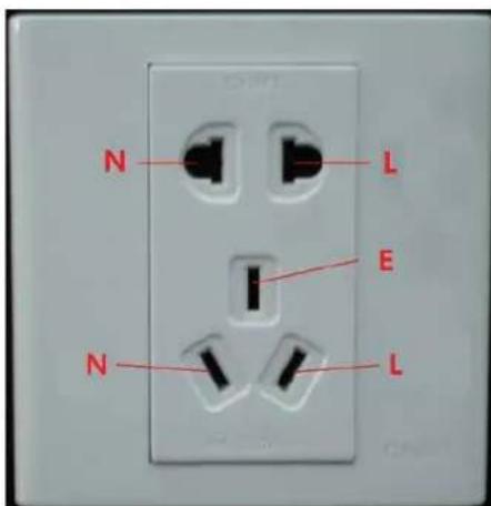
There is a shortcut way to check whether these three cables connection are standard or not (not the accurate check).

In the following operations, the multimeter range shall be at 750 V.
For E (earth cable)
Turn the digital multimeter to 750 VAC, use your one hand to hold the metal end, and then the other hand inserts the pen to the E port of the socket. See the following figure. If the multimeter shows 0, then you can see current earth cable connection is standard. If the value is more than 10, then you can know there is inductive current and the earth cable connection is not proper.
Appendix Figure 7-5 Check earth cable connection
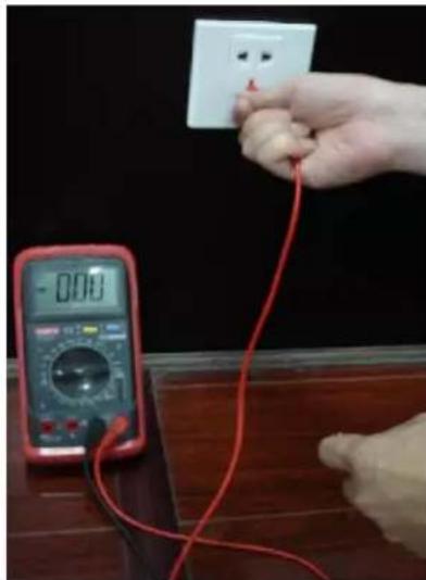
natural_image
Hand holding a white electrical outlet connected to a red wire, with a digital multimeter displaying the power supply (no text or symbols visible)For L (live cable)
Turn the digital multimeter to 750 VAC, use your one hand to hold the metal end, and then the other hand inserts the pen to the L port of the socket. See the following figure. If the multimeter shows 125, then you can see current live cable connection is standard. If the value is less than 60, then you can know current live cable connection is not proper or it is not the live cable at all.
Appendix Figure 7-6 Check live cable connection
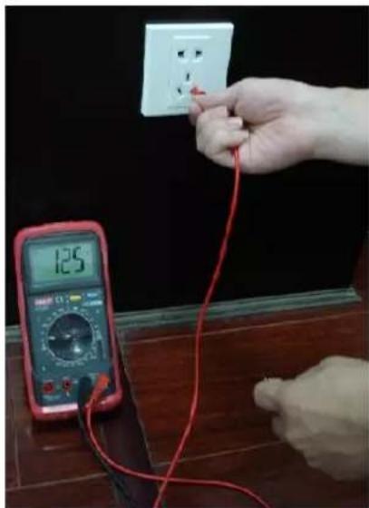
natural_image
Hand holding a white electrical outlet connected to a red multimeter on a wooden surface (no text or symbols visible)For N (Neutral cable)
Turn the digital multimeter to 750 VAC, use your one hand to hold the metal end, and then the other hand inserts the pen to the N port of the socket. See the following figure. If the multimeter shows 0, then you can see current N cable connection is standard. If the value is more than 10, then you can see there is inductive current and the neutral cable connection is not proper. If the value is 120, then you can know that you have misconnected the neutral cable to the live cable.
Appendix Figure 7-7 Check neutral cable connection
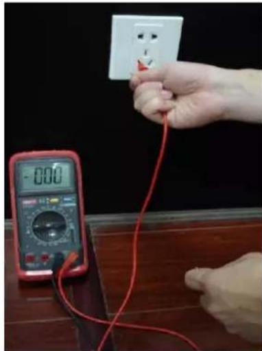
natural_image
Hand holding a white electrical outlet connected to a red wire, with a digital multimeter nearby (no visible text or symbols)Appendix 8 RJ45-RS232 Connection Cable Definition
Refer to the following figure for RJ-45 cable definition.
Appendix Figure 8-1 RJ-45
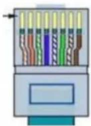
natural_image
Illustration of a multi-layered electronic device with color-coded wires (no text or symbols visible)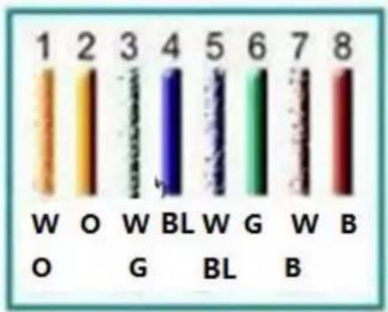
W=White O=Orange
BL=Blue G=Green
B = Brown
Refer to the following figure for RS-232 pin definition.
Appendix Figure 8-2 RS-232
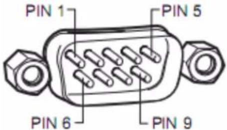
Cross Connection
Refer to the following figure for connection information.
Appendix Figure 8-3 Cross connection
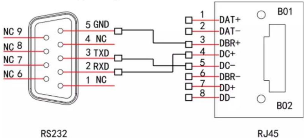
Refer to the following table for detailed crossover cable connection information.
Appendix Table 8-1 Crossover cable connection
| RJ45 (T568B) | RJ45 (Network cable) | RS-232 | Signal Description |
| 4 Blue 2 RXD | |||
| 5 White and blue 3 TXD | |||
| 3 White and green 5 GND | |||
Straight Connection
Refer to the following figure for straight cable connection information.
Appendix Figure 8-4 Straight cable connection
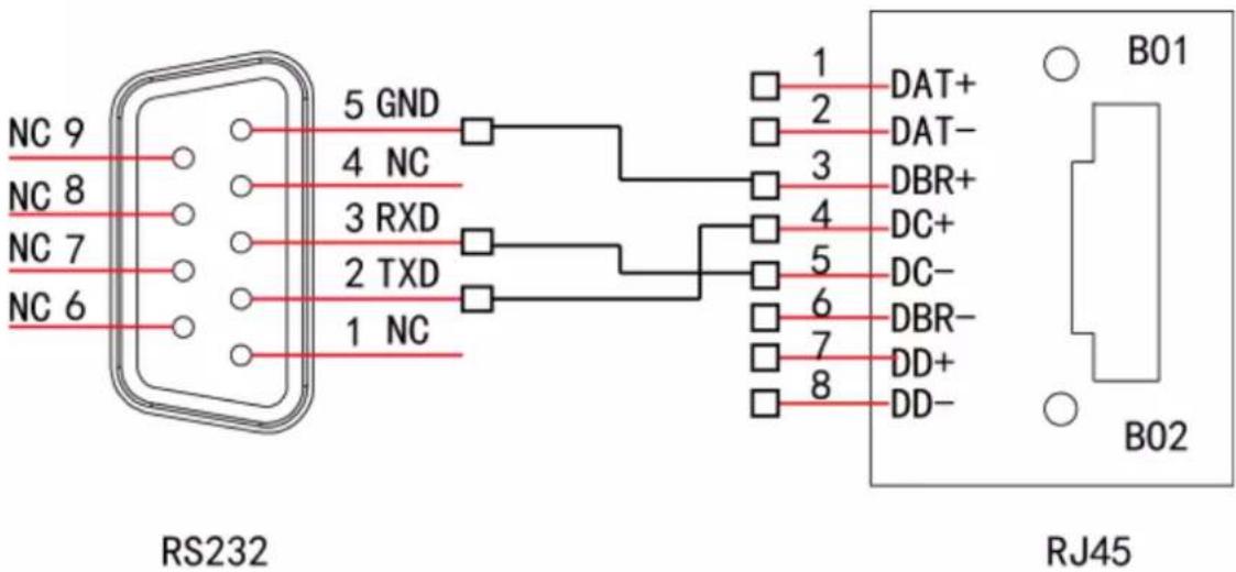
Refer to the following table for straight connection information.
Appendix Table 8-2 Straight connection
| RJ45 (T568B) | RJ45 (Network cable) | RS-232 | Signal Description |
| 4 Blue 3 RXD | |||
| 5 White and blue 2 | TXD | ||
| 3 | White and green | 5 | GND |
Appendix 9 Cybersecurity Recommendations
Cybersecurity is more than just a buzzword: it's something that pertains to every device that is connected to the internet. IP video surveillance is not immune to cyber risks, but taking basic steps toward protecting and strengthening networks and networked appliances will make them less susceptible to attacks. Below are some tips and recommendations from Dahua on how to create a more secured security system.
Mandatory actions to be taken for basic device network security:
1. Use Strong Passwords
Please refer to the following suggestions to set passwords.
- The length should not be less than 8 characters.
- Include at least two types of characters; character types include upper and lower case letters, numbers and symbols.
- Do not contain the account name or the account name in reverse order.
- Do not use continuous characters, such as 123, abc, etc.
- Do not use overlapped characters, such as 111, aaa, etc.
2. Update Firmware and Client Software in Time
- According to the standard procedure in Tech-industry, we recommend to keep your device (such as NVR, DVR, IP camera, etc.) firmware up-to-date to ensure the system is equipped with the latest security patches and fixes. When the device is connected to the public network, it is recommended to enable the "auto-check for updates" function to obtain timely information of firmware updates released by the manufacturer.
- We suggest that you download and use the latest version of client software.
"Nice to have" recommendations to improve your device network security:
1. Physical Protection
We suggest that you perform physical protection to device, especially storage devices. For example, place the device in a special computer room and cabinet, and implement well-done access control permission and key management to prevent unauthorized personnel from carrying out physical contacts such as damaging hardware, unauthorized connection of removable device (such as USB flash disk, serial port), etc.
2. Change Passwords Regularly
We suggest that you change passwords regularly to reduce the risk of being guessed or cracked.
3. Set and Update Passwords Reset Information Timely
The device supports password reset function. Please set up related information for password reset in time, including the end user's mailbox and password protection questions. If the information changes, please modify it in time. When setting password protection questions, it is suggested not to use those that can be easily guessed.
4. Enable Account Lock
The account lock feature is enabled by default, and we recommend you to keep it on to guarantee the account security. If an attacker attempts to log in with the wrong password several times, the corresponding account and the source IP address will be locked.
5. Change Default HTTP and Other Service Ports
We suggest you to change default HTTP and other service ports into any set of numbers between
1024–65535, reducing the risk of outsiders being able to guess which ports you are using.
6. Enable HTTPS
We suggest you to enable HTTPS, so that you visit Web service through a secure communication channel.
7. MAC Address Binding
We recommend you to bind the IP and MAC address of the gateway to the device, thus reducing the risk of ARP spoofing.
8. Assign Accounts and Privileges Reasonably
According to business and management requirements, reasonably add users and assign a minimum set of permissions to them.
9. Disable Unnecessary Services and Choose Secure Modes
If not needed, it is recommended to turn off some services such as SNMP, SMTP, UPnP, etc., to reduce risks.
If necessary, it is highly recommended that you use safe modes, including but not limited to the following services:
- SNMP: Choose SNMP v3, and set up strong encryption passwords and authentication passwords.
- SMTP: Choose TLS to access mailbox server.
- FTP: Choose SFTP, and set up strong passwords.
- AP hotspot: Choose WPA2-PSK encryption mode, and set up strong passwords.
10. Audio and Video Encrypted Transmission
If your audio and video data contents are very important or sensitive, we recommend that you use encrypted transmission function, to reduce the risk of audio and video data being stolen during transmission.
Reminder: encrypted transmission will cause some loss in transmission efficiency.
11. Secure Auditing
- Check online users: we suggest that you check online users regularly to see if the device is logged in without authorization.
- Check device log: By viewing the logs, you can know the IP addresses that were used to log in to your devices and their key operations.
12. Network Log
Due to the limited storage capacity of the device, the stored log is limited. If you need to save the log for a long time, it is recommended that you enable the network log function to ensure that the critical logs are synchronized to the network log server for tracing.
13. Construct a Safe Network Environment
In order to better ensure the safety of device and reduce potential cyber risks, we recommend:
- Disable the port mapping function of the router to avoid direct access to the intranet devices from external network.
- The network should be partitioned and isolated according to the actual network needs. If there are no communication requirements between two sub networks, it is suggested to use VLAN, network GAP and other technologies to partition the network, so as to achieve the network isolation effect.
- Establish the 802.1x access authentication system to reduce the risk of unauthorized access to private networks.
- Enable IP/MAC address filtering function to limit the range of hosts allowed to access the device.
More information
Please visit Dahua official website security emergency response center for security announcements and the latest security recommendations.
ENABLING A SAFER SOCIETY AND SMARTER LIVING
- AI Digital Video Recorder User's Manual
- Foreword
- General
- Safety Instructions
- Revision History
- Privacy Protection Notice
- About the Manual
- Important Safeguards and Warnings
- Operation Requirements
- Electrical Safety
- Table of Contents
- Foreword....II
- Important Safeguards and Warnings......V
- Introduction.... 1
- Getting Started.... 3
- The Grand Tour 16
- Rear Panel 22
- Remote Control Operations....34
- Mouse Operations 36
- Connection.... 38
- Connecting to Alarm Input and Output....40
- Local Configurations 43
- Configuring System Settings....332
- Viewing Information....341
- Logging out of the Device....349
- Web Operations 350
- FAQ 354
- Appendix 1 Glossary 360
- Appendix 2 HDD Capacity Calculation.... 362
- Appendix 3 Compatible Backup Devices.... 364
- Appendix 4 Compatible CD/DVD Burner List .... 371
- Appendix 5 Compatible Displayer List....372
- Appendix 6 Compatible Switcher....373
- Appendix 7 Earthing 374
- Appendix 8 RJ45-RS232 Connection Cable Definition .... 380
- Appendix 9 Cybersecurity Recommendations.... 382
- Introduction
- Overview
- Functions
- AI Function
- Real-time Surveillance
- IoT Management
- Sensor Integration
- Storage Management
- Compression Format
- Backup Function
- Record & Playback
- Network Operation
- Alarm Activation
- Communication Port
- PTZ Control
- Intelligent Operation
- UPnP (Universal Plug and Play)
- Camera Self-adaptive
- Getting Started
- Checking the Components
- Installing HDD
- DH-XVR58xxS-I2/DH-XVR58xxS-4KL-I2/DH-XVR58xxS-4KL-I2-LP/DH-XVR58xxS-I3/DH-XVR58xxS-4KL-I3/DH-XVR58xxS-4KL-I3-LP/DH-XVR78xxS-4K-I2/DH-XVR78xxS-4K-I3/DH-XVR78xxS-4KL-X-LP-V2/DH-XVR88xxS-4KL-I
- DH-XVR54xxL-I2/DH-XVR54xxL-4KL-I2/DH-XVR54xxL-I3/DH-XVR54xxL-4KL-I3/DH-XVR74xxL-4K-I2/DH-XVR74xxL-4K-I3
- DH-XVR51xxC-I3/DH-XVR51xxC-4KL-I3
- The Grand Tour
- Front Panel
- DH-XVR51xxH-I
- DH-XVR71xxH-4K-I2/DH-XVR71xxH-4K-I3/DH-XVR71xxHE-4K-I2/DH-XVR71xxHE-4K-I3/DH-XVR71xxHE-4KL-I
- DH-XVR72xxA-4KL-I/DH-XVR72xxAN-4K-I2/DH-XVR72xxA-4K-I2/DH-XVR72xxAN-4K-I3/DH-XVR72xxA-4K-I3
- DH-XVR82xxA-4K-I/DH-XVR82xxA-4KL-I
- DH-XVR78xxS-4K-I2/DH-XVR78xxS-4K-I3/DH-XVR78xxS-4KL-X-LP-V2/DH-XVR88xxS-4KL-I
- DH-XVR74xxL-4K-I2/DH-XVR74xxL-4K-I3
- DH-XVR54xxL-I2/DH-XVR54xxL-4KL-I2/DH-XVR54xxL-I3/DH-XVR54xxL-4KL-I3
- DH-XVR58xxS-I2/DH-XVR58xxS-I3/DH-XVR58xxS-4KL-I2/DH-XVR58xxS-4KL-I3/DH-XVR58xxS-4KL-I2-LP/DH-XVR58xxS-4KL-I3-LP
- DH-XVR1Bxx-I/DH-XVR1BxxH-I
- Rear Panel
- DH-XVR41xxC-I/DH-XVR41xxHS-I/DH-XVR51xxHS-I2/DH-XVR51xxHS-I3/DH-XVR51xxHS-4KL-I2/DH-XVR51xxHS-4KL-I3
- DH-XVR52xxA-I2/DH-XVR52xxA-I3/DH-XVR52xxA-4KL-I2/DH-XVR52xxA-4KL-I3/DHXVR42xxAN-I/DH-XVR42xxAN-I(V2.0)/DH-XVR52xxAN-I2/DH-XVR52xxAN-I3/DH-XVR52xxAN-4KL-I2/DH-XVR52xxAN-4KL-I3/DH-XVR72xxA-4K-I2/DH-XVR72xxA-4K-I3/DH-XVR72xxA-4KL-I/DH-XVR72xxAN-4K-I2/DH-XVR72xxAN-4K-I3
- DH-XVR82xxA-4K-I/DH-XVR82xxA-4KL-I
- DH-XVR58xxS-I2/DH-XVR58xxS-4KL-I2/DH-XVR58xxS-I3/DH-XVR58xxS-4KL-I3/DH-XVR78xxS-4K-I2/DH-XVR78xxS-4K-I3/DH-XVR88xxS-4KL-I
- DH-XVR58xxS-4KL-I2-LP/DH-XVR58xxS-4KL-I3-LP/DH-
- XVR78xxS-4KL-X-LP-V2
- DH-XVR54xxL-I2/DH-XVR54xxL-4KL-I2/DH-XVR54xxL-I3/DH-
- XVR54xxL-4KL-I3/DH-XVR74xxL-4K-I2/DH-XVR74xxL-4K-I3
- DH-XVR1Bxx-I/DH-XVR1BxxH-I
- DH-XVR51xxC-I3/DH-XVR51xxC-4KL-I3
- Remote Control Operations
- Mouse Operations
- Connection
- Typical Connection Diagram
- Connecting to Video and Audio Input and Output
- Video Input
- Guarantee the stability and reliability of the camera signal
- Guarantee stability and reliability of the transmission line
- Keep connection lugs in well contact
- Video Output
- Audio Input
- Audio Output
- Connecting to Alarm Input and Output
- Alarm input
- Alarm output
- How to connect PTZ decoder
- Make sure the front-end device has soundly earthed
- Introducing Alarm Port
- Alarm Input
- Alarm Output
- Alarm Output Relay Parameters
- Local Configurations
- Initial Settings
- Booting up
- Initializing the Device
- Step 8 Draw an unlock pattern.
- Step 9 Configure the protection parameters for password.
- Resetting Password
- Enabling Password Reset Function
- Resetting Password on Local Interface
- Step 2 Click
- Step 3 Click OK.
- Step 4 Reset the password.
- Using Reset Button on the Mainboard
- Setting Up with the Startup Wizard
- Entering Startup Wizard
- Configuring General Settings
- Configuring Date and Time Settings
- Configuring Network Settings
- Configuring P2P Settings
- Configuring Encode Settings
- Configuring Snapshot Settings
- Configuring Basic Storage Settings
- Configuring Recorded Video Storage Schedule
- Configuring Snapshot Storage Schedule
- Step 4 Click OK.
- Live View
- Live View Screen
- Live View Control bar
- Instant Playback
- Digital Zoom
- Instant Record
- Manual Snapshot
- Mute (Analog channel only)
- Warning Light (Supported on Camera with Warning Light Function)
- Siren (Supported on Camera with Siren Function)
- Two-way Talk (Digital channel Only)
- Adding Camera (Digital channel Only)
- Navigation Bar
- Shortcut Menu
- AI Preview Mode
- Channel Sequence
- Color Setting
- Live View Display
- Configuring Display Settings
- Configuring Zero-Channel Settings
- Configuring TV
- Configuring Tour Settings
- Adding a Channel Group
- Modifying a Channel Group
- Quick Operation Bar
- Shortcut Icons on Function Titles
- Shortcut Icons on Setting Menu
- Entering Main Menu
- Controlling PTZ Cameras
- Configuring PTZ Connection Settings
- Working with PTZ Control Panel
- Basic PTZ Control Panel
- Expanded PTZ Control Panel
- Configuring PTZ Functions
- Configuring Presets
- Configuring Tours
- Configuring Patterns
- Configuring Scan
- Calling PTZ Functions
- Calling Presets
- Calling Tours
- Calling Patterns
- Calling AutoScan
- Calling AutoPan
- Using AUX Button
- Calling OSD Menu
- Configuring Camera Settings
- Configuring Image Settings
- Configuring Encode Settings
- Configuring Snapshot Settings
- Configuring Encode Enhancement
- Configuring Overlay Settings
- Configuring Covered Area Settings
- Configuring Channel Type
- Step 2 Configure the channels.
- Upgrading Coaxial Camera
- Configuring Remote Devices
- Adding Remote Devices
- Initializing Remote Devices
- Adding Remote Devices Automatically
- Adding Remote Devices Manually
- Modifying or Deleting Remote Devices
- Modifying IP Address
- Exporting IP Address
- Importing IP Address
- Managing Remote Devices
- Viewing Status
- Viewing Firmware Information
- Upgrading Remote Devices
- Step 2 Upgrade the device.
- Configuring Record Settings
- Enabling Record Control
- Configuring Recorded Video Storage Schedule
- Configuring Snapshot Settings
- Configuring Snapshot Trigger
- Configuring Scheduled Snapshot
- Configuring Event Triggered Snapshot
- Configuring Snapshot Storage Schedule
- Backing up Snapshots to FTP
- Playing Back Video
- Enabling Record Control
- Instant Playback
- Video Playback
- Introducing Playback Controls Bar
- Selecting Search Type
- Clipping Recorded Video
- Backing up Recorded Video
- Smart Search
- Showing AI Rule during Playback
- Marking and Playing Back Video
- Marking a Video
- Playing Back Marked Video
- Playing Back Time before the Tag
- Managing Tagged Video
- Playing Back Snapshots
- Playing Back Splices
- Using the File List
- Locking and Unlocking the Recorded Video
- Alarm Events Settings
- Alarm Information
- Alarm Input Settings
- Configuring Local Alarms
- Configuring Alarms from Alarm Box
- Configuring Alarms from External IP Cameras
- Configuring Alarms for IP Camera Offline
- Configuring Alarms from HDCVI Devices
- Alarm Output Settings
- Configuring Alarm Output
- Configuring Warning Light
- Configuring Siren
- Related Operations
- Configuring Smart Illumination
- Video Detection
- Configuring Motion Detection Settings
- Setting the Motion Detection Region
- Setting Motion Detection Period
- Configuring Video Loss Settings
- Configuring Tampering Settings
- System Events
- Configuring HDD Event Settings
- Configuring Network Event Settings
- Step 1 Select Main Menu > ALARM > Exception > Network.
- Configuring Disarming
- AI Function
- Configuring AI Mode
- For Pro AI Series
- Face Detection
- Configuring Face Detection Parameters
- Searching for and Playing Detected Faces
- Step 5
- Face Recognition
- Face Database Management
- Creating a Face Database
- Step 2 At Type, you can select Local or Remote.
- Step 4 Enter the face database name, and then click OK.
- Adding Face Pictures
- Adding One Face Picture
- Step 6 Click OK.
- Step 7 On the Details page, click Search.
- Adding Face Pictures in Batch
- Adding the Detected Faces
- Face Recognition Configuration
- Smart Search for Face Recognition
- Step 4 Click the picture that you want to play back.
- Search by Picture
- Step 1 Select Main Menu > AI > AI Search > Face Recognition > Search by Picture.
- Step 2 Upload face pictures from Face Database or Local Upload.
- 1) Click Face Database.
- Step 6
- IVS Function
- Configuring IVS Parameters
- Step 7 Click Apply to complete the settings.
- Configuring Tripwire Rules
- Step 2 Draw a tripwire.
- Configuring Intrusion Rules
- Smart Search for IVS Function
- Video Structuring
- Configuring Video Structuring
- Smart Search for Video Structuring
- Step 4 Select one or multiple results, and then you can
- Non-motor Vehicle Detection
- For Lite AI Series
- SMD
- Configuring SMD Parameters
- Searching for SMD Reports
- Configuring IVS Function
- Configuring IVS Parameters
- Smart Search for IVS Function
- Face Detection (For XVR5X-I and XVR7X-I series only)
- Configuring Face Detection Parameters
- Searching for and Playing Detected Faces
- Face Recognition (For XVR7X-I series only)
- Face Database Management
- Adding Face Pictures in Batches
- Face Recognition Configuration
- Smart Search for Face Recognition
- Configuring IVS Mode
- Configuring Smart Schedule
- IoT Function
- Configuring Sensor Settings
- Connecting Sensor through Device
- Step 4 Click Pair.
- Step 5 Click Back to exit the pairing page.
- Connecting Sensor through Camera with Gateway
- Configuring Alarm Linkage
- Configuring Temperature and Humidity Camera
- Enabling Detecting Function
- Viewing Temperature and Humidity Data
- Exporting Temperature and Humidity Data
- Configuring Alarm Linkage
- Configuring Alarm Linkage for Temperature Data
- Configuring Alarm Settings for Humidity Data
- Searching IoT Information
- Configuring Wireless Siren
- Configuring POS Settings
- Searching the Transaction Records
- Configuring POS Settings
- Configuring Backup Settings
- Finding USB Device
- Backing up Files
- Network Management
- Configuring Network Settings
- Configuring TCP/IP Settings
- Configuring Port Settings
- Configuring Wi-Fi Connection Settings
- Configuring 3G/4G Settings
- Configuring PPPoE Settings
- Configuring DDNS Settings
- Preparation
- Procedure
- Configuring EMAIL Settings
- Configuring UPnP Settings
- Step 1 Select Main Menu > NETWORK > UPnP.
- Configuring SNMP Settings
- Configuring Multicast Settings
- Step 3 Click Apply to complete the settings.
- Configuring Register Settings
- Configuring Alarm Center Settings
- Configuring P2P Settings
- Configuring Network Testing Settings
- Testing the Network
- Capturing Packet and Backing up
- 2) Select the route.
- 3) Click OK to save the route selection settings.
- Click
- Configuring Account Settings
- Configuring User Account
- Adding a User Account
- Setting Permitted Period
- Step 1 Next to Period, click Setting.
- Step 2 Define the permitted period. By default, it is active all the time.
- Modifying a User Account
- Step 2
- Deleting a User Account
- Configuring Group Account
- Adding a Group
- Modifying a Group
- Step 1 Select Main Menu > ACCOUNT > Group.
- Deleting a Group
- Step 3
- Configuring ONVIF Users
- Audio Management
- Configuring Audio Files
- Configuring Playing Schedule for Audio Files
- Storage Management
- Configuring Basic Settings
- Configuring the Recording and Snapshot Schedule
- Configuring Disk Manager
- Configuring Record
- Configuring Advance Settings
- Configuring Disk Quota
- Configuring HDD Detecting Settings
- Checking HDD
- View Detecting Results
- Configuring Record Estimate
- Step 3 Click OK to save the settings.
- Calculating Recording Time
- Step 1 On the Rec Estimate page, click the By Space tab.
- Step 2 Click Select.
- Calculating HDD Capacity for Storage
- Configuring FTP Storage Settings
- Security Center
- Security Status
- Scanning Security Modules
- System Service
- Basic Services
- 802.1x
- HTTPS
- Attack Defense
- Firewall
- Account Lockout
- Anti-Dos Attack
- Sync Time-Allowlist
- CA Certificate
- Device Certificate
- CA Application and Import
- Import Third-Party Certificate
- Trusted CA Certificate
- Audio/Video Encryption
- Security Warning
- Security Exception
- Illegal Login
- Configuring System Settings
- Configuring General System Settings
- Configuring RS-232 Settings
- Configuring System Maintenance Settings
- Exporting and Importing System Settings
- Exporting System Settings
- Step 1 Select Main Menu > MAINTAIN > Manager > Import/Export.
- Importing System Settings
- Restoring Default Settings
- Updating the Device
- Updating File
- Performing Online Upgrade
- Uboot Upgrading
- Exporting Intelligent Diagnosis Data
- Viewing Information
- Viewing Version Details
- Viewing Log Information
- Viewing Event Information
- Viewing Network Information
- Viewing Online Users
- Viewing the Network Load
- Viewing HDD Information
- Viewing Channel Information
- Viewing Data Stream Information
- Logging out of the Device
- Menu, click
- Web Operations
- Connecting to Network
- Logging in to the Web
- Introducing Web Main Menu
- Viewing Open-source Software Notice
- FAQ
- DVR cannot boot up properly.
- DVR frequently shuts down or stops running.
- Hard disk cannot be detected.
- There is no video output whether it is one-channel, multiple-channel or all-channel output.
- Real-time video color is distorted.
- Cannot search local records.
- Video is distorted when searching local records.
- No audio under monitor state.
- There is audio under monitor state but no audio under playback state.
- System time is not correct.
- Cannot control PTZ on DVR.
- Motion detection function does not work.
- Cannot log in client-end or web.
- There is only mosaic no video when preview or playback video file remotely.
- Network connection is not stable.
- Burn error /USB back error.
- Keyboard cannot control DVR
- Alarm signal cannot be disarmed.
- Alarm function is null.
- Remote control does not work.
- Record storage period is not enough.
- Cannot playback the downloaded file.
- Forgot local menu operation password or network password
- When I login via HTTPS, a dialogue says the certificate for this website is for other address.
- When I login via HTTPS, a dialogue says the certificate is not trusted.
- When I login via HTTPS, a dialogue says the certificate has expired or is not valid yet.
- I connect the general analog camera to the device, there is no video output.
- I connect the standard definition analog camera or the coaxial camera to the device, there is no video output.
- I cannot connect to the IP channel.
- After I connected to the IP channel, the one-window output is OK, but there is no multiple-window output.
- After I connected to the IP channel, the multiple-window output is OK, but there is no one-window output.
- After I connected to the IP channel, there is no video output in the one-window or the multiple-window mode. But I can see there is bit stream.
- DDNS registration failed or cannot access the device domain name.
- I cannot use the P2P function on my cell phone or the web.
- I connect the standard definition camera to the device, there is no video output.
- I cannot connect to the IP camera.
- Daily Maintenance
- Appendix 1 Glossary
- Appendix 2 HDD Capacity Calculation
- Appendix 3 Compatible Backup Devices
- Appendix 3.1 Compatible USB List
- Appendix 3.2 Compatible SD Card List
- Appendix 3.3 Compatible Portable HDD List
- Appendix 3.4 Compatible USB DVD List
- Appendix 3.6 Compatible SATA HDD List
- Appendix 4 Compatible CD/DVD Burner List
- Appendix 5 Compatible Displayer List
- Appendix 6 Compatible Switcher
- Appendix 7 Earthing
- Appendix 7.1 What is the Surge
- Appendix 7.2 The Earthing Modes
- Appendix 7.3 Thunder Proof Ground Method in the Monitor System
- Appendix 7.4 The Shortcut Way to Check the Electric System by Digital Multimeter
- For E (earth cable)
- For L (live cable)
- For N (Neutral cable)
- Appendix 8 RJ45-RS232 Connection Cable Definition
- Straight Connection
- Appendix 9 Cybersecurity Recommendations
- Mandatory actions to be taken for basic device network security:
- Use Strong Passwords
- Update Firmware and Client Software in Time
- "Nice to have" recommendations to improve your device network security:
- Physical Protection
- Change Passwords Regularly
- Set and Update Passwords Reset Information Timely
- Enable Account Lock
- Change Default HTTP and Other Service Ports
- Enable HTTPS
- MAC Address Binding
- Assign Accounts and Privileges Reasonably
- Disable Unnecessary Services and Choose Secure Modes
- Audio and Video Encrypted Transmission
- Secure Auditing
- Network Log
- Construct a Safe Network Environment
- More information
- ENABLING A SAFER SOCIETY AND SMARTER LIVING
Brand : Dahua Technology
Model : XVR5208AN-4KL-I2
Category : Video recorder