
IVSS7024-16M - Video recorder Dahua Technology - Free user manual and instructions
Find the device manual for free IVSS7024-16M Dahua Technology in PDF.


| Product Type | Network Video Recorder (NVR) |
| Model Number | IVSS7024-16M |
| Brand | Dahua Technology |
| Video Input Channels | 24 channels |
| Maximum Recording Resolution | 16MP per channel |
| Video Compression | Smart H.265+/H.265/Smart H.264+/H.264 |
| Recording Rate | Up to 480 fps at 1080p |
| Hard Drive Bays | 2 SATA III HDDs (up to 10TB each) |
| RAID Support | RAID 0/1/5/6/10 |
| Network Interface | 2 Gigabit Ethernet ports |
| PoE Ports | None (supports PoE via Dahua PoE switch if needed) |
| Video Output | 1 HDMI (4K), 1 VGA |
| Audio | 1 audio input, 1 audio output (RCA) |
| Alarm I/O | 16 alarm inputs, 6 alarm outputs |
| Power Supply | AC 100-240V, 50/60Hz, 1.5A |
| Power Consumption | ≤ 25W (without HDD) |
| Dimensions (W×D×H) | 440mm × 410mm × 70mm (1U form factor) |
| Weight | Approximately 4.5 kg (without HDD) |
| Operating Temperature | 0°C to +50°C |
| Operating Humidity | 10% to 90% (non-condensing) |
| Certifications | CE, FCC, UL |
| Compatible Cameras | Dahua IP cameras up to 16MP |
| Remote Access | Via web browser, mobile app (DMSS), or VMS |
| Maintenance | Clean with dry cloth; avoid liquids |
| Spare Parts Availability | Power supply unit, HDD tray, fan module |
Frequently Asked Questions - IVSS7024-16M Dahua Technology
User questions about IVSS7024-16M Dahua Technology
0 question about this device. Answer the ones you know or ask your own.
Ask a new question about this device
Download the instructions for your Video recorder in PDF format for free! Find your manual IVSS7024-16M - Dahua Technology and take your electronic device back in hand. On this page are published all the documents necessary for the use of your device. IVSS7024-16M by Dahua Technology.
USER MANUAL IVSS7024-16M Dahua Technology
natural_image
Abstract geometric composition with gray and red shapes (no text or symbols)Foreword
General
This manual introduces the installation, functions and operations of the intelligent video surveillance server (hereinafter referred to as "the Device" or "IVSS"). Read carefully before using the device, and keep the manual safe for future reference.
Models
Refer to the interface of each model for function details.

- In the model name, R indicates that the model has redundant power.
- In the model name, D indicates that the model has an LCD screen.
Safety Instruction
The following signal words might appear in the manual.
| Signal Words | Meaning | |
 | WARNING | Indicates a high potential hazard which, if not avoided, will result in death or serious injury. |
 | WARNING | Indicates a medium or low potential hazard which, if not avoided, could result in slight or moderate injury. |
 | CAUTION | Indicates a potential risk which, if not avoided, could result in property damage, data loss, reductions in performance, or unpredictable results. |
 | TIPS Provides | methods to help you solve a problem or save time. |
 | NOTE | Provides additional information as a supplement to the text. |
Revision History
| Version | Revision Content | Release Time |
| V5.0.2 | Updated IVS description. | May 2022 |
| V5.0.1 | Added anti-corrosion descriptions.Updated ANPR description. | March 2022 |
| V5.0.0 | Added the talk function on the view window.Added the audio and light alarm.Deleted the strategy of shortcut RAID creation. | October 2021 |
| V4.0.0 | Added 1:1 face recognition.Added one-click disarming.Added SSD health detection.Added related search of face images and human body images.Added entries frequency. | June 2021 |
| V3.3.0 | Added HDD installation introduction to the 8-HDD series.Added IVSS-M series. | December 2020 |
| V3.2.0 | Added passerby database.Added IVS model switchAdded algorithm version in the device list.Added Re-extract Eigenvector Again.Optimized people-counting, call alarm and smoking alarm. | November 2020 |
| V3.0.4 | Optimized storage and recording configuration.Added PTZ settings.Added call detection and smoking detection. | July 2020 |
| V3.0.3 | Added IVSS7116, IVSS7116DR, IVSS7124 and IVSS7124DR. | April 2020 |
| V3.0.1 | Added crowd distribution, and data security notes. | December 2019 |
| V3.0.0 | Added search by image, cluster, and fisheye dewarp.Updated chapters including intelligent operation and device management according to the new device version. | December 2019 |
| V2.1.0 | Added video metadata, vehicle recognition, and vehicle comparison functions.Updated the intelligent operation chapter. | June 2019 |
| V2.0.1 | Added attention in important safeguards and warnings. | January 2019 |
| V2.0.0 | Updated figures of 16-HDD series IVSS. | December 2018 |
| V1.0.0 | First release. | November 2018 |
Privacy Protection Notice
As the device user or data controller, you might collect the personal data of others such as their face, fingerprints, and license plate number. You need to be in compliance with your local privacy protection laws and regulations to protect the legitimate rights and interests of other people by implementing measures which include but are not limited: Providing clear and visible identification to inform people of the existence of the surveillance area and provide required contact information.
About the Manual
- The manual is for reference only. Slight differences might be found between the manual and the product.
- We are not liable for losses incurred due to operating the product in ways that are not in compliance with the manual.
- The manual will be updated according to the latest laws and regulations of related jurisdictions. For detailed information, see the paper user's manual, use our CD-ROM, scan the QR code or visit our official website. The manual is for reference only. Slight differences might be found between the electronic version and the paper version.
- All designs and software are subject to change without prior written notice. Product updates might result in some differences appearing between the actual product and the manual. Please contact customer service for the latest program and supplementary documentation.
- There might be errors in the print or deviations in the description of the functions, operations and technical data. If there is any doubt or dispute, we reserve the right of final explanation.
- Upgrade the reader software or try other mainstream reader software if the manual (in PDF format) cannot be opened.
- All trademarks, registered trademarks and company names in the manual are properties of their respective owners.
- Please visit our website, contact the supplier or customer service if any problems occur while using the device.
- If there is any uncertainty or controversy, we reserve the right of final explanation.
Icons and Buttons
| Icon/Button | Description |
 | After you have entered password, click the icon, you can see the password is displayed in letters and number. Release mouse or move pointer to other places, the password is displayed in the form of black dots. |
 | Add icon. Click the icon, system can display the hidden APPLICATIONS window. You can view or open the applications. |
 | Help information. Point to the icon, device can display help information. |
 | Display or hide icon. Click the icon to display the hidden menu. Now the icon is shown as √/≫/▼. Click √/≫/▼ again to hide the menu items. |
 | Check the box. You can select multiple menu items at the same time.√ means selected. |
 | Check the box to select one menu item, ○ means selected. |
 | Drop-down box. Click the box to view the drop-down menu. |
 | Enable icon.: Disabled.: Enabled: The function cannot be enabled.: The function cannot be disabled. |
| Reset Click to clear all search criteria settings. | |
  1/2 > 1/2 > | Page switch./: Page up/page down./: Go to the first page or the last page. |
 | Filter icon. Click the icon to set filter criteria. |
 | Select icon. Click the icon, the system displays a checkbox, so you can select multiple objects. |
 | Search column. Enter key words, click to search the corresponding information. |
 Text column. Enter number, letter, symbol and so on. Text column. Enter number, letter, symbol and so on. | |
 Close button. Click the icon to close the window. Close button. Click the icon to close the window. | |
Important Safeguards and Warnings
This section introduces content covering the proper handling of the Device, hazard prevention, and prevention of property damage. Read carefully before using the Device, comply with the guidelines when using it, and keep the manual safe for future reference.
Operation Requirements

WARNING
- This is a class A product. In a domestic environment this may cause radio interference in which case you may be required to take adequate measures.
- The Device is heavy and needs to be carried by several persons together to avoid personal injuries.

- Check whether the power supply is correct before use.
- Do not unplug the power cord on the side of the Device while the adapter is powered on.
- Operate the Device within the rated range of power input and output.
- Use the Device under allowed humidity and temperature conditions.
- Do not drop or splash liquid onto the Device, and make sure that there is no object filled with liquid on the Device to prevent liquid from flowing into it.
- Do not disassemble the Device without professional instruction.
- Your configurations will be lost after performing a factory reset. Please be advised.
- Do not restart, shut down or disconnect the power to the Device during an update.
Make sure the update file is correct because an incorrect file can result in a Device error occurring.
◇ The system cannot upgrade different types of AI modules at the same time.
- Do not frequently turn on/off the Device. Otherwise, the product life might be shortened.
- Back up important data on a regular basis when using the Device.
- Operating temperature: 0 °C to 45 °C (32 °F to 113 °F).
- Salt pray in the operating environment of the device might corrode its electronic components and cables. To ensure the normal operation of the device and prolong its service life, use the device in an indoor environment that is 3 kilometers away from the sea.
Installation Requirements

WARNING
- Do not connect the power adapter to the Device while the adapter is powered on.
- Strictly comply with the local electric safety code and standards. Make sure the ambient voltage is stable and meets the power supply requirements of the Device.
- Do not expose the battery to environments with extremely low air pressure, or extremely high or low temperatures. Also, it is strictly prohibited for the battery to be thrown into a fire or furnace, and to cut or put mechanical pressure on the battery. This is to avoid the risk of fire and explosion.
- Use the standard power adapter or cabinet power supply. We will assume no responsibility for
any injuries or damages caused by the use of a nonstandard power adapter.
!
- Do not place the Device in a place exposed to sunlight or near heat sources.
- Keep the Device away from dampness, dust, and soot.
- Put the Device in a well-ventilated place, and do not block its ventilation.
• Install the server on a stable surface to prevent it from falling. - The power supply must conform to the requirements of ES1 in IEC 62368-1 standard and be no higher than PS2. Note that the power supply requirements are subject to the Device label.
- The Device is a class I electrical appliance. Make sure that the power supply of the Device is connected to a power socket with protective earthing.
- Use power cords that conform to your local requirements, and are rated specifications.
- Before connecting the power supply, make sure the input voltage matches the server power requirement.
- When installing the Device, make sure that the power plug and appliance coupler can be easily reached to cut off power.
• Install the server in an area that only professionals can access.
- Extra protection is necessary for the Device casing to reduce the transient voltage to the defined range.
- If you did not push the HDD box to the bottom, then do not close the handle to avoid damage to the HDD slot.
• Install the Device near a power socket for emergency disconnect.
- It is prohibited for non-professionals and unauthorized personnel to open the Device casing.
- Affix the Device securely to the building before use.
Maintenance Requirements

WARNING
- Make sure to use the same model when replacing the battery to avoid fire or explosion. Dispose the battery strictly according to the instructions on it.
● Power off the Device before maintenance.

- AI module does not support hot plug. If you need to install or replace the AI module, unplug the Device power cord first. Otherwise, it will lead to file damage on the AI module.
- The Device casing provides protection for internal components. Use a screwdriver to loosen the screws before detaching the casing. Make sure to put the casing back on and secure it in its original place before powering on and using the Device.
- It is prohibited for non-professionals and unauthorized personnel to open the Device casing.
- The appliance coupler is a disconnection Device. Keep it at a convenient angle when using it. Before repairing or performing maintenance on the Device, first disconnect the appliance coupler.
Transportation Requirements

Transport the Device under allowed humidity and temperature conditions.
Storage Requirements

Store the Device under allowed humidity and temperature conditions.
Table of Contents
Foreword....
Important Safeguards and Warnings....V
1 Overview .... 1
1.1 Introduction....1
1.2 Login Mode .... 1
2 The Grand Tour .... 2
2.1 8-HDD Series....2
2.1.1 Front Panel 2
2.1.2 Rear Panel....3
2.1.3 Dimensions....5
2.2 12-HDD Series....5
2.2.1 Front Panel 5
2.2.2 Rear Panel....6
2.2.3 Dimensions....9
2.3 16-HDD Series....9
2.3.1 Front Panel 9
2.3.2 Rear Panel....11
2.3.3 Dimensions....15
2.4 24-HDD Series....16
2.4.1 Front Panel 16
2.4.2 Rear Panel....17
2.4.3 Dimensions....21
3 Hardware Installation ....23
3.1 Installation Flow 23
3.2 Unpacking the Box 23
3.3 HDD Installation....24
3.3.1 8-HDD Series....24
3.3.2 12-HDD Series ....26
3.3.3 16/24-HDD Series ....27
3.4 Cable Connection....28
3.4.1 Alarm Connection 29
4 Starting the Device ....34
5 Initial Settings....35
5.1 Initializing Device....35
5.2 Quick Settings....37
5.2.1 Configuring IP Address....37
5.2.2 Configuring P2P Settings 39
5.3 Login....40
5.3.1 Logging in to PCAPP Client 40
5.3.2 Logging in to Local Interface....42
5.3.2.1 Preparation....43
5.3.2.2 Operation Steps....43
5.3.3 Logging in to Web Interface 43
5.4 Configuring Remote Device....44
5.4.1 Initializing Remote Device 44
5.4.2 Adding Remote Device....48
5.4.2.1 Smart Add....48
5.4.2.2 Manual Add ....51
5.4.2.3 RTSP....53
5.4.2.4 Batch Add ....54
6 AI Operations....57
6.1 Overview....57
6.2 Face Detection....58
6.2.1 Enabling AI Plan 58
6.2.2 Configuring Face Detection....58
6.2.3 Live View of Face Detection....60
6.2.3.1 Setting AI Display ....60
6.2.3.2 Live View 61
6.2.3.3 Face Records 62
6.2.4 Face Search....63
6.2.4.1 Searching by Property....63
6.2.4.2 Searching by Image....66
6.2.4.2.1 Searching Devices....66
6.2.4.2.2 Searching Face Database....69
6.2.4.2.3 Searching Task Lists....70
6.2.4.3 Exporting Face Records....71
6.3 Face Recognition....73
6.3.1 Configuration Modes....73
6.3.2 Face Recognition by Camera....73
6.3.2.1 Configuration Procedure....73
6.3.2.2 Enabling AI Plan ....73
6.3.2.3 Configuring Remote Face Database....73
6.3.2.3.1 Creating Face Database for Remote Devices 73
6.3.2.3.2 Adding Face Images for Remote Devices....75
6.3.2.4 Configuring Face Recognition (by Camera) 78
6.3.2.5 Live View of Face Recognition ....79
6.3.2.5.1 Setting AI Display....79
6.3.2.5.2 Live View 80
6.3.2.5.3 Face Total....81
6.3.2.6 Face Search....82
6.3.2.6.1 Searching by Property 82
6.3.2.6.2 Searching by Property 84
6.3.2.6.3 Searching by Image 84
6.3.2.6.4 Exporting Face Records 84
6.3.2.6.5 1:1 Face Recognition....84
6.3.3 Face Detection by Camera + Face Recognition by Device 85
6.3.3.1 Configuration Procedure 85
6.3.3.2 Enabling AI Plan 85
6.3.3.3 Configuring Face Detection (by Camera) 85
6.3.3.4 Configuring Device Face Database....87
6.3.3.4.1 Creating Human Face Database....87
6.3.3.4.2 Exporting Face Database 88
6.3.3.4.3 Adding Face Image 89
6.3.3.4.4 Creating Passerby Database....94
6.3.3.4.5 Human Face Abstract....96
6.3.3.4.6 Managing Face Pictures....97
6.3.3.5 Configuring Face Recognition (by Device) 98
6.3.3.6 Live View 100
6.3.3.7 Face Search....100
6.3.4 Face Recognition by Camera + Face Recognition by Device....100
6.3.4.1 Configuration procedure....100
6.3.4.2 Enabling AI Plan 101
6.3.4.3 Configuring Face Recognition (by Camera) 101
6.3.4.4 Configuring Device Face Database....101
6.3.4.5 Configuring Face Recognition (by Device) 101
6.3.4.6 Live View 101
6.3.4.7 Face Search....101
6.3.5 Face Detection by Device + Face Recognition by Device 101
6.3.5.1 Configuration Procedure 101
6.3.5.2 Configuring Face Detection (by Device) 101
6.3.5.3 Configuring Device Face Database....103
6.3.5.4 Configuring Face Recognition (by Device) 103
6.3.5.5 Live View 103
6.3.5.6 Face Search....103
6.3.6 Video Metadata + Face Recognition by Device....103
6.3.6.1 Configuration Procedure 103
6.3.6.2 Enabling AI Plan 104
6.3.6.3 Configuring Video Metadata....104
6.3.6.4 Configuring Face Recognition (by Device) 104
6.3.6.5 Live View 104
6.3.6.6 Face Search....104
6.4 People Counting....104
6.4.1 Enabling AI Plan....104
6.4.2 Configuring People Counting....105
6.4.3 Configuring In Area No....106
6.4.4 Configuring Queuing Detection 107
6.4.5 Live View....108
6.4.6 Viewing AI Report....109
6.5 Video Metadata....111
6.5.1 Enabling AI Plan....111
6.5.2 Configuring Video Metadata 111
6.5.3 Live View of Video Metadata 113
6.5.3.1 Setting AI Display 113
6.5.3.2 Live View 114
6.5.3.3 Detection Statistics....115
6.5.3.3.1 Human....115
6.5.3.3.2 Motor Vehicle....116
6.5.3.3.3 Non-motor Vehicle 116
6.5.4 AI Search 117
6.5.4.1 Human Search....117
6.5.4.1.1 Searching by Property 117
6.5.4.1.2 Searching by Image 120
6.5.4.2 Vehicle Search 125
6.5.4.3 Non-motor Vehicle Search....127
6.6 IVS 129
6.6.1 Enabling AI Plan 129
6.6.2 Configuring IVS....129
6.6.2.1 Switching IVS Model....129
6.6.2.2 Global Configuration 129
6.6.2.3 Rule Configuration....130
6.6.3 Live View of IVS 134
6.6.3.1 Setting AI Display 134
6.6.3.2 Live View 136
6.6.3.3 Detection Statistics....136
6.6.4 IVS Search....137
6.7 Vehicle Recognition 138
6.7.1 Enabling AI Plan 138
6.7.2 Setting Vehicle Recognition....138
6.7.3 Live View of Vehicle Recognition 139
6.7.3.1 Setting AI Display 139
6.7.3.2 Live View 140
6.7.3.3 Detection Statistics....141
6.7.4 Searching for Detection Information 142
6.8 ANPR....142
6.8.1 Procedure 142
6.8.2 Setting Vehicle Detection 142
6.8.3 Configuring Vehicle Database 142
6.8.3.1 Creating Vehicle Database....142
6.8.3.2 Registering Vehicle Information 144
6.8.3.2.1 Manual Add....144
6.8.3.2.2 Batch Import....145
6.8.3.2.3 Adding from Detection Results....147
6.8.3.3 Managing Vehicle Information 147
6.8.3.3.1 Editing Vehicle Information.... 148
6.8.3.3.2 Copying Vehicle Information 148
6.8.3.3.3 Deleting Vehicle Information....149
6.8.4 Configuring Number Plate Comparison....149
6.8.5 Live View of ANPR 150
6.8.5.1 Setting AI Display 150
6.8.5.2 Live View 151
6.8.5.3 Detection Statistics....152
6.8.6 AI Search....153
6.8.6.1 Searching by Property....153
6.8.6.2 Searching by Database 155
6.9 Crowd Distribution Map 156
6.9.1 Enabling AI Plan....157
6.9.2 Configuring Crowd Distribution Map....157
6.9.2.1 Global Configuration 157
6.9.2.2 Rule Configuration....157
6.9.3 Live View of Crowd Distribution 158
6.10 Call Alarm 159
6.10.1 Enabling AI Plan....159
6.10.2 Configuring Call Alarm....159
6.10.3 Live View of Call Alarm....160
6.10.4 Call Alarm Search....161
6.11 Smoking Alarm 162
6.11.1 Enabling AI Plan....163
6.11.2 Configuring Smoking Alarm....163
6.11.3 Live View of Smoking Alarm....164
7 General Operations....165
7.1 Live and Monitor 165
7.1.1 View Management....166
7.1.1.1 View Group 167
7.1.1.1.1 Creating View Group....167
7.1.1.1.2 Operation....168
7.1.1.2 View 169
7.1.1.2.1 Creating View....169
7.1.1.2.2 Editing View....172
7.1.1.2.3 Enabling view....173
7.1.1.3 View Window 175
7.1.1.3.1 Task Column 175
7.1.1.3.2 Shortcut Menu....177
7.1.1.3.3 Digital Zoom....178
7.1.1.3.4 Searching by Image 179
7.1.1.3.5 Fisheye Dewarp....179
7.1.1.3.6 Smart Tracking 181
7.1.1.3.7 Thermal 181
7.1.1.3.8 Talk....182
7.1.2 Resources Pool....183
7.1.3 PTZ 184
7.1.3.1 PTZ Menu Settings....186
7.1.3.2 Configuring PTZ Functions....187
7.1.3.2.1 Setting a Preset....187
7.1.3.2.2 Setting a Cruise 189
7.1.3.2.3 Setting a Pattern.... 189
7.1.3.2.4 Setting Linear Scanning....190
7.1.3.2.5 Enabling Auxiliary Functions....191
7.2 Recorded Files....191
7.2.1 Playing Back Recorded Video 191
7.2.2 Clipping Recorded Video....196
7.2.3 Playing Back Snapshots....197
7.2.4 Exporting File 200
7.2.5 Video Tag....202
7.2.6 Locking Files 203
7.3 File Management 203
7.3.1 Face Management....203
7.3.2 Vehicle Management....204
7.3.3 Tag Management....204
7.3.4 File Lock 204
7.3.5 Voice Management....205
7.3.6 Watermark Verification....206
7.4 Task Management....207
7.4.1 AI Analysis Task 207
7.4.1.1 Configuration Procedure 207
7.4.1.2 Importing Task Resources 208
7.4.1.3 Creating AI Analysis Task....208
7.4.1.4 Viewing Analysis Results....210
7.4.2 Extracting Eigenvector Again....210
7.5 Backup 211
7.6 Alarm List 213
7.7 Display Management 214
7.7.1 Multiple-screen Control 214
7.7.2 Locking Screen....216
7.8 System Info....216
7.9 Background Task 217
7.10 Buzzer 217
8 System Configuration....218
8.1 Configuration Window....218
8.2 Device Management....218
8.2.1 Viewing Device Information 219
8.2.2 Remote Device....221
8.2.2.1 Viewing Remote Devices....221
8.2.2.2 Changing IP Address....221
8.2.2.2.1 Modifying IP of Unconnected Devices 222
8.2.2.2.2 Modifying IP of Connected Devices....223
8.2.2.3 Configuring Remote Devices 224
8.2.2.3.1 Configuring Device Property....225
8.2.2.3.2 Configuring Connection Information 225
8.2.2.3.3 Configuring Video Parameters....227
8.2.2.3.4 Configuring OSD 228
8.2.2.3.5 Configuring Audio Parameters....230
8.2.2.4 Exporting Remote Devices in Batches....231
8.2.2.5 Importing Remote Devices in Batches....232
8.2.2.6 Connecting Remote Devices....232
8.2.2.7 Deleting Remote Devices 232
8.2.2.8 Changing Device Password 233
8.3 Network Management....233
8.3.1 Basic Network....234
8.3.1.1 Configuring IP Address....234
8.3.1.2 Port Aggregation 236
8.3.1.2.1 Binding NIC 237
8.3.1.2.2 Cancelling Binding NIC 239
8.3.1.3 Setting Port Number 239
8.3.2 Network Apps....240
8.3.2.1 P2P 240
8.3.2.2 DDNS....241
8.3.2.2.1 Preparation 241
8.3.2.2.2 Procedure....242
8.3.2.3 Email....243
8.3.2.4 SNMP 244
8.3.2.5 Register 246
8.3.2.6 UPnP 247
8.3.2.7 Multicast....249
8.3.2.8 Alarm Center 250
8.3.2.9 Route Table....250
8.4 Event Management....251
8.4.1 Alarm Actions....251
8.4.1.1 Record 253
8.4.1.2 Buzzer 253
8.4.1.3 Log 254
8.4.1.4 Email....254
8.4.1.5 Preset 254
8.4.1.6 Snapshot 255
8.4.1.7 Local Alarm Out 255
8.4.1.8 Remote Device Alarm Output....255
8.4.1.9 Access 256
8.4.1.10 Voice Prompt....256
8.4.1.11 Smart Tracking....256
8.4.1.12 Report Alarm 257
8.4.1.13 Audio and Light Alarm 257
8.4.2 Local Device 258
8.4.2.1 One-click Disarming 258
8.4.2.2 Abnormal Event....259
8.4.2.3 Offline Alarm....260
8.4.2.4 Configuring AI Application 261
8.4.2.4.1 Viewing AI Plan 261
8.4.2.4.2 Setting AI Display 262
8.4.2.4.3 Setting Entries Frequency....264
8.4.2.4.4 Video Diagnosis 265
8.4.2.5 Configuring Device Alarm 267
8.4.3 Remote Device 268
8.4.3.1 Video Detection....268
8.4.3.1.1 Configuring Video Motion....268
8.4.3.1.2 Tampering 270
8.4.3.2 Offline Alarm....271
8.4.3.3 IPC External Alarm....271
8.4.3.4 Thermal Alarm....272
8.5 Storage Management 273
8.5.1 Storage Resource 274
8.5.1.1 Local Hard Disk 274
8.5.1.1.1 Viewing S.M.A.R.T....274
8.7.1.1 Adding User Group 302
8.7.1.2 Deleting User Group 303
8.7.2 Device User....303
8.7.2.1 Adding a User 303
8.7.2.2 Operation....305
8.7.3 Password Maintenance....305
8.7.3.1 Changing Password....305
8.7.3.1.1 Changing Password of the Current User 306
8.7.3.1.2 Changing Password of Other User 306
8.7.3.2 Resetting Password 307
8.7.3.2.1 Leaving Email Address and Security Questions....307
8.7.3.2.2 Resetting Password on Local Interface 307
8.7.3.2.3 Resetting Password on the Web....310
8.7.4 ONVIF 312
8.7.4.1 Adding ONVIF User 312
8.7.4.2 Deleting ONVIF User 313
8.8 System Configuration 314
8.8.1 Setting System Parameters....314
8.8.2 System Time....315
8.8.3 Display 317
8.8.4 Schedule 318
8.9 Cluster Service 319
8.9.1 Configuring Cluster 319
8.9.1.1 Creating a Cluster 319
8.9.1.2 Viewing Details 321
8.9.1.3 Configuring Arbitration IP 322
8.9.2 Record Synchronization....322
8.9.3 Viewing Cluster Log 323
9 System Maintenance....324
9.1 Overview....324
9.2 System Information....325
9.2.1 Viewing Device Information 325
9.2.2 Viewing Legal Information 326
9.2.3 Viewing Algorithm Version....326
9.3 System Resources....327
9.3.1 Viewing Device Resource 327
9.3.2 Viewing AI Module Information....327
9.4 Logs....328
9.4.1 Log Classification....328
9.4.2 Log Search 328
9.5 Intelligent Diagnosis 329
9.5.1 Run Log 329
9.5.2 One-click Export 330
9.6 Network Care....330
9.6.1 Online User 330
9.6.2 Packet Capture....331
9.7 Device Maintenance 332
9.7.1 Updating Device 332
9.7.1.1 Updating the Device 332
9.7.1.2 Updating AI Module 332
9.7.1.3 Updating Cameras....333
9.7.2 Default 333
9.7.3 Automatic Maintenance....334
9.7.4 IMP/EXP 334
9.8 Disk Maintenance....335
9.8.1 S.M.A.R.T Detection 335
9.8.2 SSD Health Detection 335
9.8.3 Firmware Update 336
10 PCAPP Introduction....337
10.1 Page Description....337
10.2 History Record....337
10.3 Viewing Downloads 337
10.4 Configuring PCAPP 338
10.5 Viewing Version Details....339
11 Log Out, Reboot, Shut Down, Lock 340
12 FAQ....342
Appendix 1 Glossary ....343
Appendix 2 Mouse and Keyboard Operations....345
Appendix 2.1 Mouse Operations....345
Appendix 2.2 Virtual Keyboard....346
Appendix 3 RAID....348
Appendix 4 HDD Capacity Calculation .... 350
Appendix 5 Particulate and Gaseous Contamination Specifications ....351
Appendix 5.1 Particulate Contamination Specifications .... 351
Appendix 5.2 Gaseous Contamination Specifications .... 351
Appendix 6 Cybersecurity Recommendations....353
1 Overview
1.1 Introduction
As an intelligent video surveillance server (hereinafter referred to as IVSS or the Device), IVSS delivers not only the basic video surveillance functions, but also a bunch of advanced AI features including face recognition, perimeter protection, video metadata and ANPR, providing AI-based all-in-one surveillance solution for customers.
- General functions: Video surveillance, video storage, alarm, record search and playback, intelligent analysis features.
- User-friendly interface.
- 4K and H.265 decoding.
- Applicable to scenarios such as intelligent building, large parking lot, financial planning area and more.
1.2 Login Mode
You can operate the device by using the local interface, web client and PCAPP client (the PC client, hereinafter referred to as PCAPP).

Operation and system configuration in this manual is mainly based on PCAPP. There might be differences from local or web operation.
Table 1-1 Login mode
| Login Mode | Operation | Description |
| Local | Connect the display, mouse and keyboard to the device. View and operate the local menu on the display. | Support all functions of the device. |
| Web | Connect the device and PC into the same network, and remotely access the device through browser (Google Chrome and Firefox) on PC. | Support majority functions of the device, except live, record playback, video download and other video-related functions. |
| PCAPP | Connect the device and PC into the same network, download and install PCAPP on PC, and then remotely access the device with PCAPP. | Support all functions of the device. |
2 The Grand Tour
This section introduces front panel, rear panel, port function and button function, indicator light status, and so on.
2.1 8-HDD Series
2.1.1 Front Panel
Figure 2-1 Front panel

natural_image
Front view of a heat exchanger with labeled ports (1-5) and an internal connector (no text or symbols beyond labels)Table 2-1 Front panel description
| No. | Button/Port | Description |
| 1 Power | Boot up or shut down device. Power indicator light status is as follows:When device is off (indicator light is off), press the button for a short period to boot up device.When device is running, (blue indicator light is on), press the button for at least 4 seconds to shut down the device. | |
| 2 Alarm indicator light | Displays local input alarm status.The indicator light is off: There is no local alarm input event.Red indicator light is on: There is local alarm input event. | |
| 3 | System status indicator light | Displays the system running status.The blue light is on: Device is running properly.The indicator light is off: The device is not running. |
| 4 Network | indicator light | Displays current network status.The indicator light is blue: It means at least one Ethernet port has connected to the network.The indicator light is off: No Ethernet ports are connected to the network. |
| 5 USB | Connects to external devices such as USB storage device, keyboard and mouse. | |
2.1.2 Rear Panel
Figure 2-2 IVSS7008 rear panel
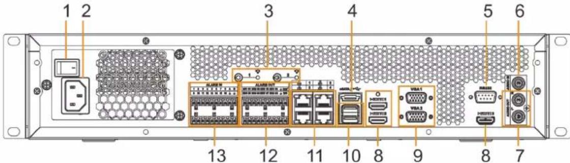
Figure 2-3 IVSS7008-M rear panel
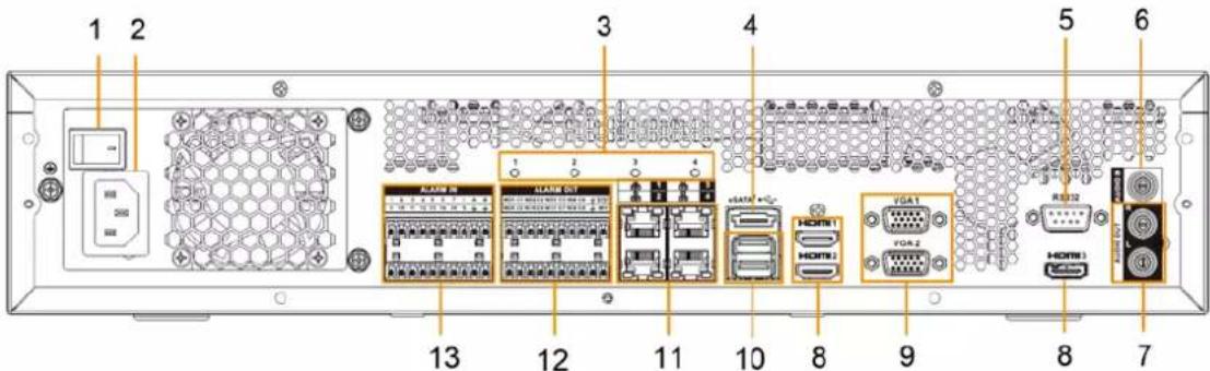
Figure 2-4 IVSS7108-M rear panel
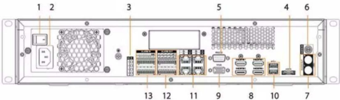
Table 2-2 Rear panel description
| No. | Button/Port | Description |
| 1 | Power | Power on-off button. |
| 2 | Power input | Inputs 100–240 VAC power. |
| 3 | AI module indicator light | Displays AI module status.● Yellow light flashes: AI module is running properly.● Yellow light is on: AI module is malfunctioning.This function is not available without AI module. |
| 4 eSATA | SATA peripheral port. Connect to SATA port or eSATA device. | |
| 5 RS-232 | RS-232 COM debug. It is for general COM debug, set IP address, transmit transparent COM data. | |
| 6 AUDIO | IN Audio input port. | |
| 7 AUDIO | OUT Audio output port. | |
| 8 HDMI | High definition audio and video signal output port.The port outputs the uncompressed high definition video and multi-channel audio data to the connected display with HDMI port. The HDMI ports are different source output. | |
| 9 VGA | VGA video output port. Output analog video signal. It can connect to the monitor to view analog video. The VGA ports are different source output. VGAn and HDMIIn are same source output. For example:VGA1 and HDMI 1 are same source output.VGA2 and HDMI 2 are same source output. | |
| 10 USB | Connects to external devices such as USB storage device, keyboard and mouse. | |
| 11 Network | 10/100/1000 Mbps self-adaptive Ethernet port. Connect to the network cable. | |
| 12 Alarm output | 8 groups of alarm output ports (NO1 C1-NO8 C8). Output alarm signal to the alarm device. Please make sure there is power to the external alarm device.NO: Alarm output port of Normally Open type.C: Common alarm output port.:GND end. | |
| 13 Alarm input | 16 groups (1-16) alarm input ports, they are corresponding to ALARM 1-ALARM 16. The alarm becomes valid in low level.A and B: Control the A/B cable of the RS-485 device. It is used to connect to the PTZ camera. Please parallel connect 120 Ω between A/B cables if there are too many PTZ decoders.:GND end. |
2.1.3 Dimensions
Figure 2-5 Dimension (mm [inch])
![481.7[18.96] 90.8[3.57] 439.7[17.31] 422.0[16.61] 446.2[17.57]](/content/2026/05/1061580/images/d0b81c01f0638dd042a5fae0dd477d8e482d480b3dfa4527c421999dd275ea30.jpg)
2.2 12-HDD Series
2.2.1 Front Panel
Figure 2-6 Front panel
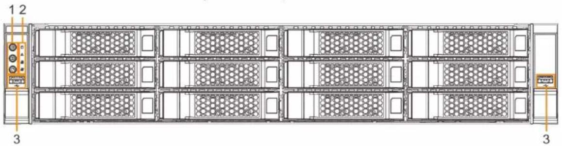
Table 2-3 Front panel description
| No. | Button/Port | Description |
| 1 | Power | Boot up or shut down device. Power indicator light status is as follows:When device is off (indicator light is off), press the button for a short period to boot up device.When device is running, (blue indicator light is on), press the button for at least 4 seconds to shut down the device. |
| ID button | Position button. It is to used control the ID indicator light on the rear panel to position the device.ID button has the indicator light function. Its display status is the same with the ID indicator light on the rear panel. | |
| RESET button | Click to restart the device. | |
| 2 | Power indicator light | Displays power status.● Amber light is on: The device has properly connected to the power source.● The indicator light is off: The device has not connected to the power source. |
| Alarm indicator light | Displays local input alarm status.● Green light on: There is no local alarm input alarm.● Red indicator light is on: There is local alarm input event. | |
| Network indicator light 1 | Displays network statuses of Ethernet port 1 and Ethernet port 2.● The indicator light flashes green: At least one Ethernet port has connected to the network.● The indicator light is off: All Ethernet ports are not connected to the network. | |
| Network indicator light 2 | Displays network statuses of Ethernet port 3 and Ethernet port 4.● The indicator light flashes green: At least one Ethernet port has connected to the network.● The indicator light is off: All Ethernet ports are not connected to the network. | |
| 3 USB port | Connects to external devices such as USB storage device, keyboard and mouse. |
2.2.2 Rear Panel
Figure 2-7 IVSS7012 rear panel (the single-power series)
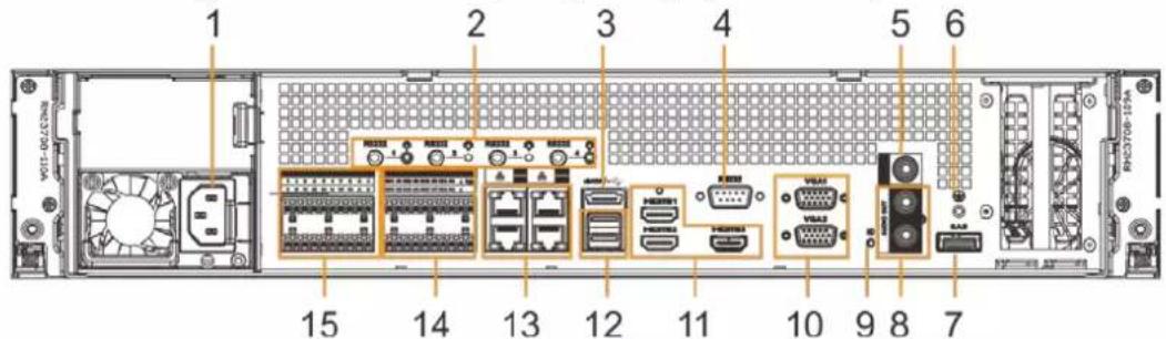
Figure 2-8 IVSS7012 rear panel (the redundant series)
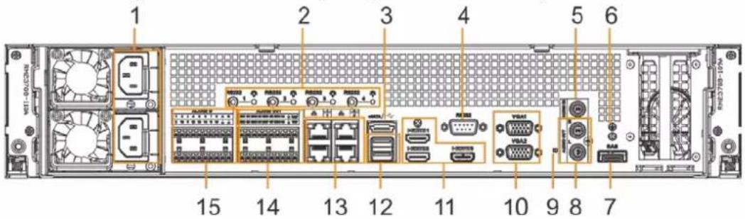
Figure 2-9 IVSS7012-M rear panel
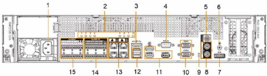
Figure 2-10 IVSS7112 rear panel (the single-power series)
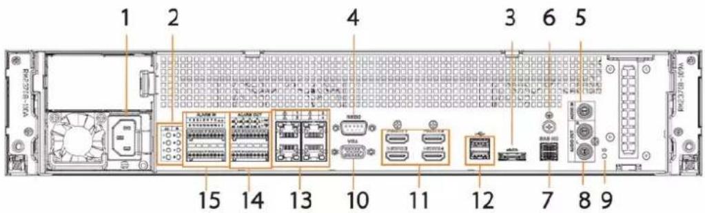
Figure 2-11 IVSS7112 rear panel (the redundant series)
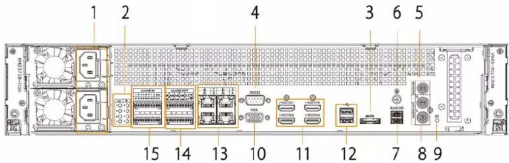
Table 2-4 Rear panel description
| No. | Name | Description |
| 1 | Power input port | Inputs 100–240 VAC power. |
| 2 AI module indicator light | Displays AI module status.The yellow light flashes: AI module is running properly.The yellow light is on: AI module is malfunctioning.This function is not available without AI module. | |
| 3 eSATA port | SATA peripheral port. Connect to SATA port or eSATA device. | |
| 4 RS-232 port | RS-232 COM debug. It is for general COM debug, set IP address, transmit transparent COM data. | |
| 5 AUDIO IN Audio input port. | ||
| 6 GND Ground port. | ||
| 7 SAS port | SAS extension port. It can connect to the SAS extension controller. | |
| 8 AUDIO OUT Audio output port. | ||
| 9 ID indicator light | Positioning indicator light. It is controlled by the ID button on the front panel.The blue light is on, device is positioning now.The indicator light is off: The device is not positioning. | |
| 10 VGA port | VGA video output port. Output analog video signal. It can connect to the monitor to view analog video. The VGA ports are different source output. VGAn and HDMI in are same source output. For example:VGA1 and HDMI 1 are same source output.VGA2 and HDMI 2 are same source output. | |
| 11 HDMI port | High definition audio and video signal output port. The port outputs the uncompressed high definition video and multi-channel audio data to the connected display with HDMI port. The HDMI ports are different source output. | |
| 12 USB port | Connects to external devices such as USB storage device, keyboard and mouse. | |
| 13 Network port | 10/100/1000 Mbps self-adaptive Ethernet port. Connect to the network cable. | |
| 14 Alarm output | 8 groups of alarm output ports (NO1 C1-NO8 C8). Output alarm signal to the alarm device. Please make sure there is power to the external alarm device.NO: Alarm output port of Normally Open type.C: Common alarm output port.:GND end. | |
| 15 Alarm input | 16 groups (1-16) alarm input ports, they are corresponding to ALARM 1-ALARM 16. The alarm becomes valid in low level.A and B: Control the A/B cable of the RS-485 device. It is used to connect to the PTZ camera. Please parallel connect 120Ω between A/B cables if there are too many PTZ decoders.:GND end. | |
2.2.3 Dimensions
Figure 2-12 Dimensions (mm [inch])
![482.6[19.00] 87.0[3.43] 482.6[19.00] 579.2[22.80] 604.3[23.79] 447.6[17.62]](/content/2026/05/1061580/images/c2a6006a7135df179f3b427c6dd82a63c33d3597c210e69d6f59cd255b3d7eab.jpg)
2.3 16-HDD Series

- The Device has an embedded display on select models.
- The Device has power redundancy on select models.
2.3.1 Front Panel
Figure 2-13 Front panel with LCD
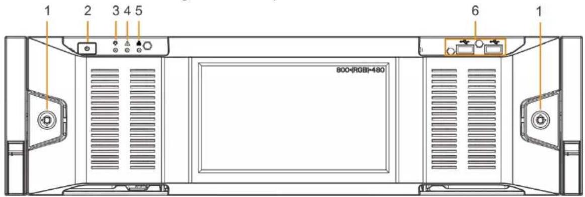
Figure 2-14 Front panel without LCD
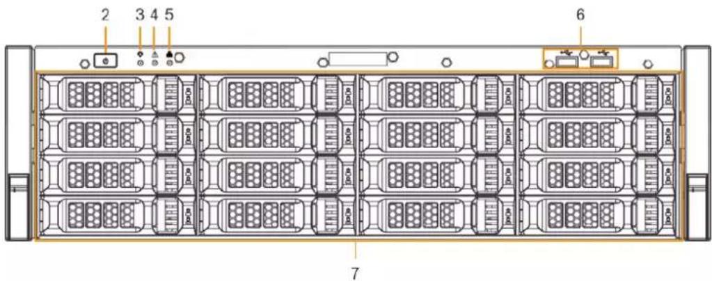
Table 2-5 Front panel description
| No. | Button/Port | Description |
| 1 Front panel lock | Once the front panel lock is secure, it can prevent HDD from being stolen or removed by mistake. Unlock the front panel lock and remove the front panel, you can view 16 HDD slots. | |
| 2 Power | Boot up or shut down device. The power on-off button has the indicator light. It can display device-running status.When device is off (indicator light is off), press the button for a short period to boot up device.When device is running, (blue indicator light is on), press the button for at least 4 seconds to shut down the device. | |
| 3 | System status indicator light | Displays the system running status.The blue light is on: Device is running properly.The indicator light is off: The device is not running. |
| 4 Alarm indicator light | Displays local input alarm status.Red indicator light is on: There is local alarm input event.The indicator light is off: There is no local alarm input event. | |
| 5 | Network indicator light | Displays current network status.The indicator light is blue: It means at least one Ethernet port has connected to the network.The indicator light is off: No Ethernet ports are connected to the network. |
| 6 USB port | Connects to external devices such as USB storage device, keyboard and mouse. | |
| 7 16-HDD slot | After you remove the front panel, you can see there are 16 HDDs. From the left to the right and from the top to the bottom, it ranges from 1-4, 5-8, 9-12, and 13-16.There are two indicator lights on the HDD slot: HDD indicator light and HDD read/write indicator light.: HDD indicator light. The light is yellow after you install the HDD.: Read/write indicator light. The blue light flashes when it is reading and writing data. | |
2.3.2 Rear Panel
Figure 2-15 IVSS7016 rear panel (single power)
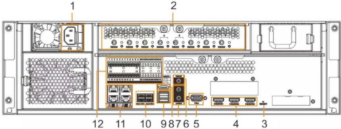
Figure 2-16 IVSS7016 rear panel (redundant power)
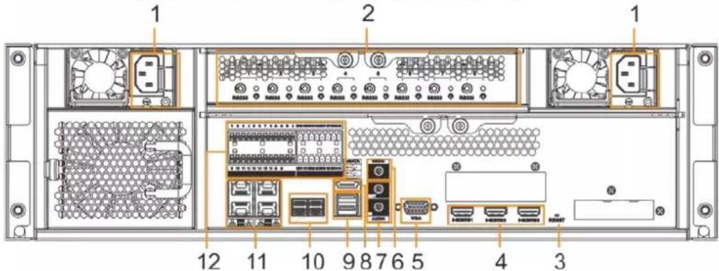
Figure 2-17 IVSS7016-M rear panel (single power)
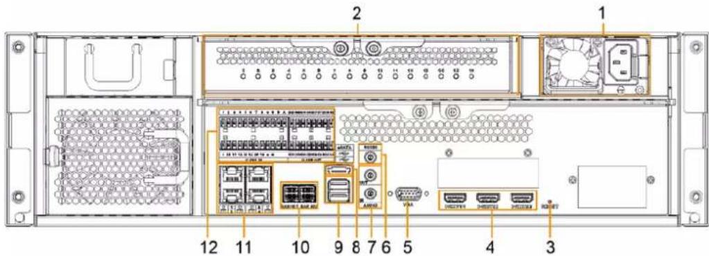
Figure 2-18 IVSS7016-M rear panel (redundant power)
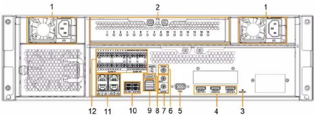
Table 2-6 IVSS7016 rear panel description
| No. | Name | Description |
| 1 | Power input port | Inputs 100–240 VAC power. |
| 2 AI module | indicator light | Displays AI module status.The yellow light flashes: AI module is running properly.The yellow light is on: AI module is malfunctioning.This function is valid if there is AI module. |
| 3 RESET button | Reserved. | |
| 4 HDMI port | High definition audio and video signal output port. The port outputs the uncompressed high definition video and multi-channel audio data to the connected display with HDMI port. The three HDMI ports are different source output. | |
| 5 VGA port | VGA video output port. It outputs analog video signal. The VGA port and HDMI 1 port are same source output. | |
| 6 RS-232 port | RS-232 COM debug. It is used for general COM debug, setting IP address, and transmitting transparent COM data. | |
| 7 | AUDIO IN Audio input port | |
| AUDIO OUT Audio output port | ||
| 8 eSATA port | SATA peripheral port. Connects to SATA port or eSATA device. | |
| 9 USB port | Connects to external devices such as USB storage device, keyboard and mouse. | |
| 10 SAS port | SAS extension port. It can connect to the SAS extension controller. | |
| 11 Network port | 10/100/1000 Mbps self-adaptive Ethernet port. Connects to the network cable. | |
| 12 Alarm Input | Alarm Output | 16 groups (1–16) alarm input ports. They are corresponding to ALARM 1–ALARM 16. The alarm becomes valid in low level.A and B: Control the A/B cable of the RS–485 device. It is used to connect to the PTZ camera. Please connect 120Ω between A/B cables if there are too many PTZ decoders.: GND end.8 groups of alarm output ports (NO1 C1–NO8 C8). They output alarm signal to the alarm device.Please make sure there is power to the external alarm device.NO: Alarm output port of Normally Open type.C: Common alarm output port.:GND end. |
Figure 2-19 IVSS7116 rear panel (single power)
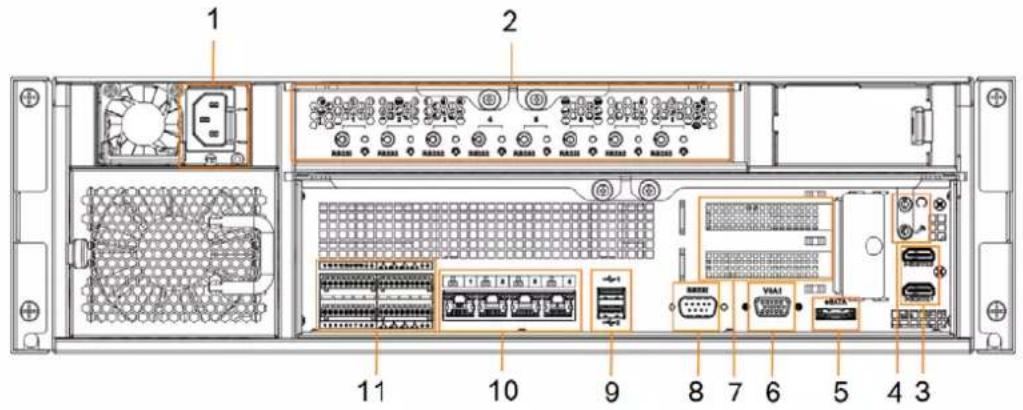
Figure 2-20 IVSS7116 rear panel (redundant power)
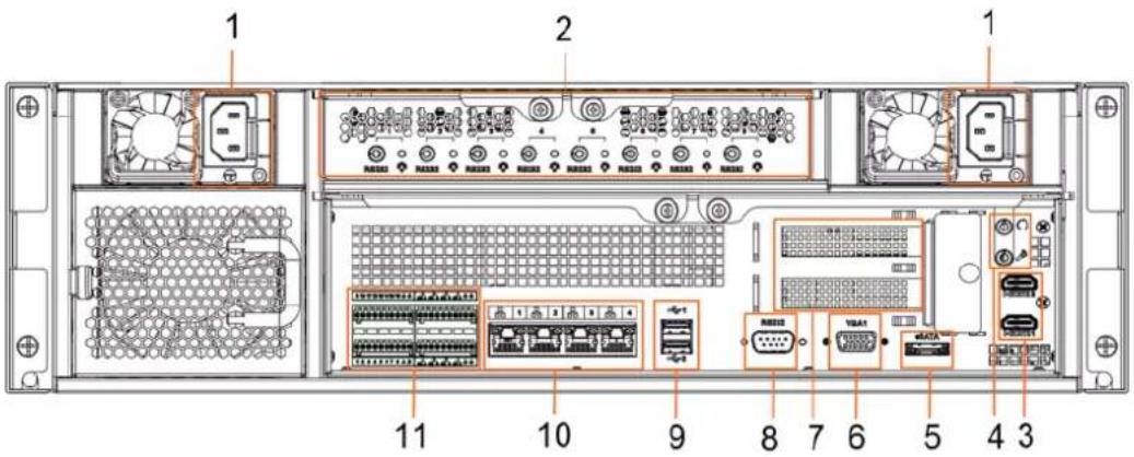
Table 2-7 IVSS7116 rear panel description
| No. | Name | Description |
| 1 Power input port | Inputs 100-127 VAC/200-240 VAC power. Some devices only have one power port. | |
| 2 AI module | indicator light | Displays AI module status.The yellow light flashes: AI module is running properly.The yellow light is on: AI module is malfunctioning.This function is not available without AI module. |
| 3 HDMI port | High definition audio and video signal output port. The port outputs the uncompressed high definition video and multi-channel audio data to the connected display with HDMI port. The two HDMI ports are different source output. | |
| 4 | AUDIO IN Audio input port. | |
| AUDIO OUT | Audio output port | |
| 5 eSATA port | SATA peripheral port. Connects to SATA port or eSATA device. | |
| 6 VGA port | VGA video output port. It outputs analog video signal. The VGA port and HDMI 1 port are same source output. | |
| 7 | PCI-E X4 | PCI Express port. It supports X4 slot. |
| 8 RS-232 port | RS-232 COM debug. It is used for general COM debug, setting IP address, and transmitting transparent COM data. | |
| 9 USB port | Connects to external devices such as USB storage device, keyboard and mouse. | |
| 10 Network port | 10/100/1000 Mbps self-adaptive Ethernet port. Connects to the network cable. | |
| 11 | Alarm Input | 16 groups (1–16) alarm input ports. They are corresponding to ALARM 1–ALARM 16. The alarm becomes valid in low level.A and B: Control the A/B cable of the RS–485 device. It is used to connect to the PTZ camera. Please connect 120Ω between A/B cables if there are too many PTZ decoders.:GND end. |
| Alarm Output | 8 groups of alarm output ports (NO1 C1–NO8 C8). They output alarm signal to the alarm device. Please make sure there is power to the external alarm device.NO: Alarm output port of Normally Open type.C: Common alarm output port.:GND end. | |
2.3.3 Dimensions
Figure 2-21 Dimensions with LCD (mm [inch])
![485.0[19.09] 133.2[5.24] 444.8[17.51] 522.4[20.67] 539.4[21.24]](/content/2026/05/1061580/images/2eea4f04c7c25ab355d765900038346055e888a70b4ff41b321ffca70194f6d4.jpg)
Figure 2-22 Dimensions without LCD (mm [inch])
![485.0[19.09] 133.2[5.24] 444.8[17.51] 522.4[20.57]](/content/2026/05/1061580/images/32d22d7ba02a369b3374620672434ae155ffd08c0a25df593506556f68592f30.jpg)
2.4 24-HDD Series
2.4.1 Front Panel
Figure 2-23 Front panel with LCD
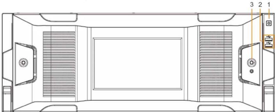
Figure 2-24 Front panel without LCD
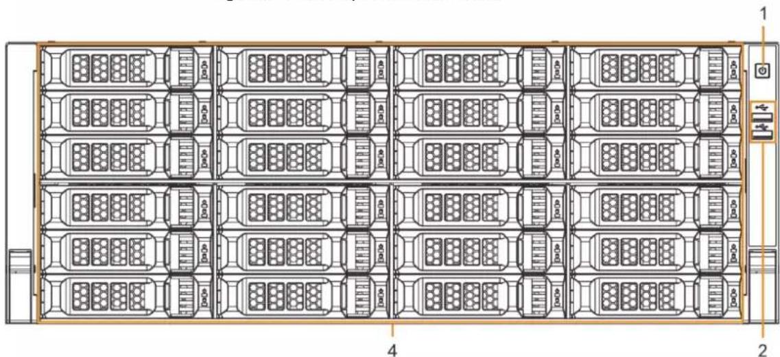
Table 2-8 Front panel description
| No. | Button/Port | Description |
| 1 | Power on-off button | Boot up or shut down device. The power on-off button has the indicator light. It can display device-running status.When device is off (indicator light is off), press the button for a short period to boot up device.When device is running, (blue indicator light is on), press the button for at least 4 seconds to shut down the device. |
| 2 USB port | Connects to external devices such as USB storage device, keyboard and mouse. | |
| 3 Front panel lock | Once the front panel lock is secure, it can prevent HDD from being stolen or removed by mistake. Unlock the front panel lock and remove the front panel, you can view 16 HDD slots. | |
| 4 24-HDD slot | After you remove the front panel, you can see there are 24 HDDs. From the left to the right and from the top to the bottom, it ranges from 1–4, 5–8, 9–12, 13–16, 17–20, and 21–24.There are two indicator lights on the HDD slot: HDD indicator light and HDD read/write indicator light.: HDD indicator light. The light is yellow after you install the HDD.: Read/write indicator light. The blue light flashes when it is reading and writing data. | |
2.4.2 Rear Panel
Figure 2-25 IVSS7024 rear panel (single power)
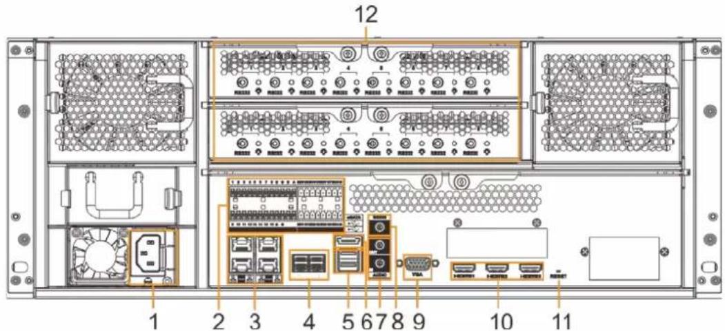
Figure 2-26 IVSS7024 rear panel (redundant power)
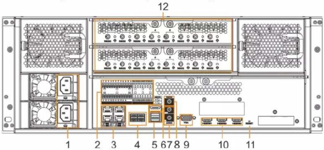
Figure 2-27 IVSS7024-M rear panel (single power)
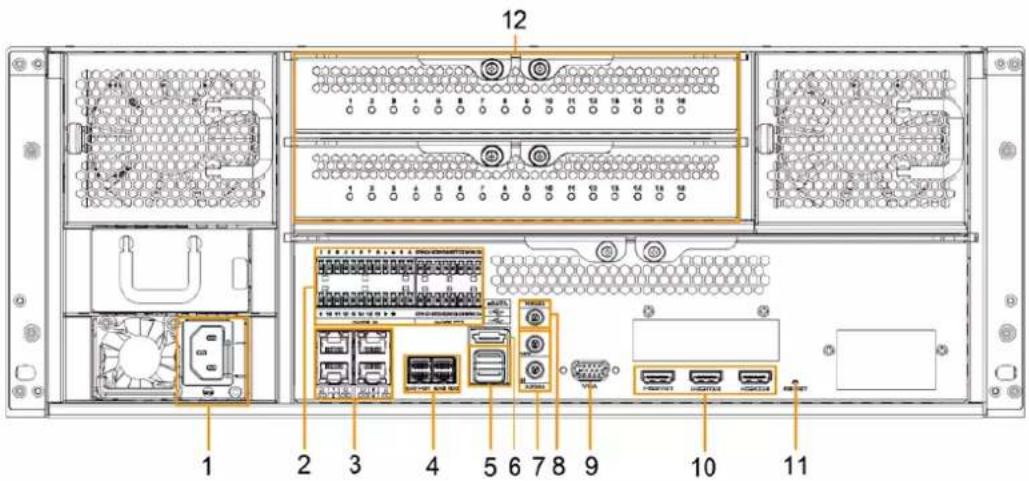
Figure 2-28 IVSS7024-M rear panel (redundant power)
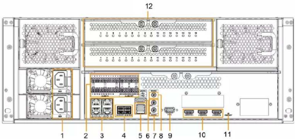
Table 2-9 Rear panel description (1)
| No. | Button/Port | Description |
| 1 | Power input port | Inputs 100–240 VAC power. |
| 2 | Alarm Input | 16 groups (1–16) alarm input ports. They are corresponding to ALARM 1–ALARM 16. The alarm becomes valid in low level.A and B: Control the A/B cable of the RS–485 device. It is used to connect to the PTZ camera.Please connect 120 Ω between A/B cables if there are too many PTZ decoders.:GND end. |
| Alarm Output | 8 groups of alarm output ports (NO1 C1–NO8 C8). They output alarm signal to the alarm device. Please make sure there is power to the external alarm device.NO: Alarm output port of Normally Open type.C: Common alarm output port.:GND end. | |
| 3 Network port | 10/100/1000Mbps self-adaptive Ethernet port. Connects to the network cable. | |
| 4 SAS port | SAS extension port. It can connect to the SAS extension controller. | |
| 5 USB port | Connects to external devices such as USB storage device, keyboard and mouse. | |
| 6 eSATA port | SATA peripheral port. Connects to SATA port or eSATA device. | |
| 7 | AUDIO IN Audio input port. | |
| AUDIO OUT Audio output port | ||
| 8 RS-232 port | RS-232 COM debug. It is used for general COM debug, setting IP address, and transmitting transparent COM data. | |
| 9 VGA port | VGA video output port. It outputs analog video signal. The VGA port and HDMI 1 port are same source output. | |
| 10 HDMI port | High definition audio and video signal output port. The port outputs the uncompressed high definition video and multi-channel audio data to the connected display with HDMI port. The three HDMI ports are different source output. | |
| 11 RESET button Reserved. | ||
| 12 AI module indicator light | Displays AI module status.The yellow light flashes: AI module is running properly.The yellow light is on: AI module is malfunctioning.This function is not available without AI module. | |
Figure 2-29 IVSS7124 rear panel (single power)
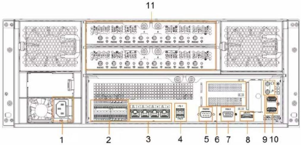
Figure 2-30 IVSS7124-M rear panel (redundant power)
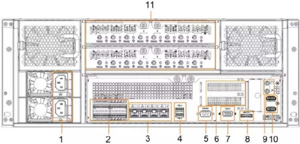
Table 2-10 Rear panel description (2)
| No. | Name | Description |
| 1 | Power input port | Inputs 100V-127V/200-240V AC power. |
| 2 | Alarm Input | 16 groups (1–16) alarm input ports. They are corresponding to ALARM 1–ALARM 16. The alarm becomes valid in low level.A and B: Control the A/B cable of the RS–485 device. It is used to connect to the PTZ camera.Please connect 120Ω between A/B cables if there are too many PTZ decoders.: GND end. |
| Alarm Output | 8 groups of alarm output ports (NO1 C1–NO8 C8).They output alarm signal to the alarm device. Please make sure there is power to the external alarm device.NO: Alarm output port of Normally Open type.C: Common alarm output port.: GND end. | |
| 3 Network | port | 10/100/1000Mbps self-adaptive Ethernet port.Connects to the network cable. |
| 4 USB port | Connects to external devices such as USB storage device, keyboard and mouse. | |
| 5 RS-232 port | RS-232 COM debug. It is used for general COM debug, setting IP address, and transmitting transparent COM data. | |
| 6 | PCI-E X4 | PCI Express port. It supports X4 slot. |
| 7 VGA port | VGA video output port. It outputs analog video signal. The VGA port and HDMI 1 port are same source output. | |
| 8 eSATA port | SATA peripheral port. Connects to SATA port or eSATA device. | |
| 9 AUDIO IN | Audio input port.AUDIO OUT Audio output port | |
| 10 HDMI port | High definition audio and video signal output port.The port outputs the uncompressed high definition video and multi-channel audio data to the connected display with HDMI port. The two HDMI ports are different source output. | |
| 11 AI module indicator light | Displays AI module status.The yellow light flashes: AI module is running properly.The yellow light is on: AI module is malfunctioning.This function is not available without AI module. | |
2.4.3 Dimensions
Figure 2-31 Dimensions with LCD (mm [inch])
![482.6[19.00] 175.0[6.89] 446.0[17.56] 514.5[20.26] 543.45[21.40]](/content/2026/05/1061580/images/5f6e8bafbd954599e067517b42b9f940e11cb3bc87f75b9f00218d3455e2735f.jpg)
Figure 2-32 Dimensions without LCD (mm [inch])
![482.6[19.00] 175.0[6.89] 446.0[17.56] 514.5[20.26]](/content/2026/05/1061580/images/3035a7b270f4f98d704eae88d5988d616d0b316d1d0526a94e37178da2b22c49.jpg)
3 Hardware Installation
This section introduces HDD installation, cable connection, and so on.

Some series product is heavy. It needs several persons to carry or move, in order to prevent person injury.
3.1 Installation Flow
Figure 3-1 Installation flow

flowchart
graph LR
    A["Start"] --> B["Unpack"]
    B --> C["Install HDD"]
    C --> D["Connect Cable"]
    D --> E["Boot up"]
    E --> F["Finish"]
3.2 Unpacking the Box
When you receive the Device, please check against the following checking list. If any of the items are missing or damaged, contact the local retailer or after-sales engineer immediately.
Table 3-1 Checking list
| No. | Item | Content | |
| 1 Whole package | Appearance | Check whether there is any visible damage. | |
| Package | Check whether there is any accidental clash during transportation. | ||
| Accessories (list of accessories on the warranty card) | Check whether they are complete. | ||
| 2 Device | Appearance | Check whether there is any visible damage. | |
| Device model | Check whether the model is the same as order contract. | ||
| The label on the device | Check whether it is torn or not.Do not tear off, or discard the label.Usually you need to show the serial number when we provide after-sales service. | ||
3.3 HDD Installation
The section introduces the detailed operations to install HDD.

Different models support different HDD numbers.
3.3.1 8-HDD Series
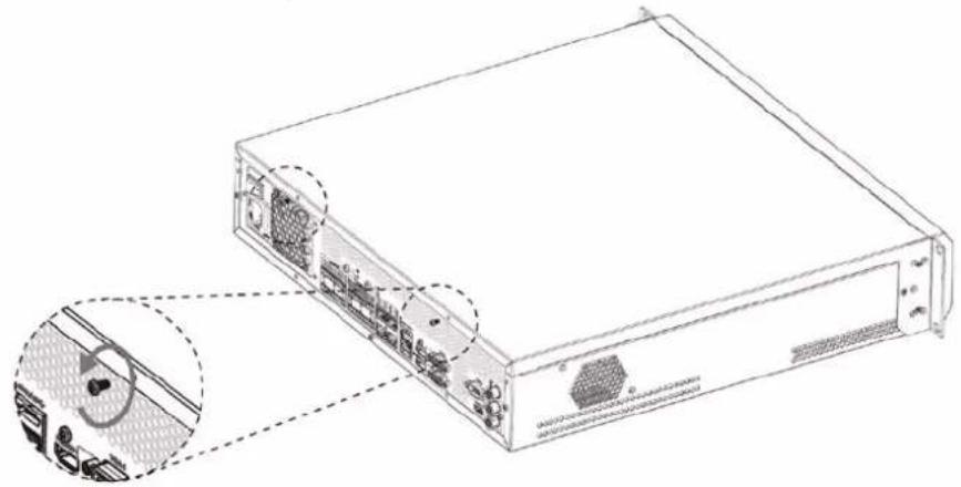
Step 1 Remove the 2 screws on the rear panel.
Figure 3-2 Remove screws
natural_image
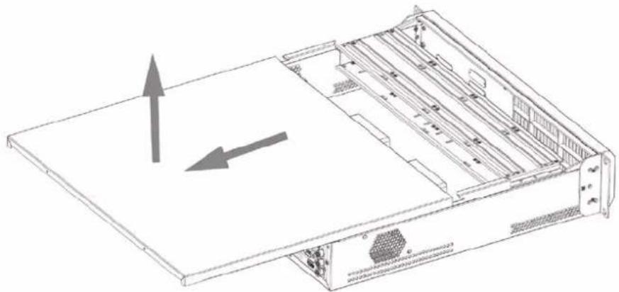
Technical line drawing of a server rack with internal components and an inset close-up showing internal wiring (no text or symbols)Step 2 Remove the chassis cover in the direction indicated by the arrow.
Figure 3-3 Remove chassis cover
natural_image
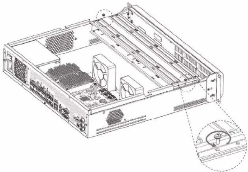
Technical line drawing of a server rack with an open top panel and internal compartments (no text or symbols)Step 3 Remove the screws on the edge of the HDD holder, and then remove the holder.
Figure 3-4 Remove HDD holder
natural_image
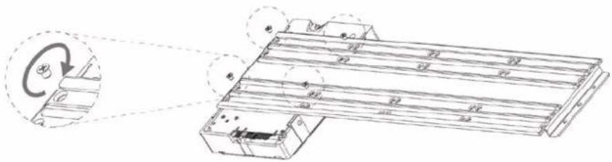
Technical line drawing of a server rack with ventilation ducts and fan components (no text or labels)Step 4 Align the 4 screw holes on the HDD to the 4 screw holes on the HDD holder, and then tighten the screws.
Figure 3-5 Install HDD (1)
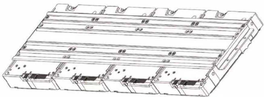
Step 5 Repeat step 4 to install the other HDDs on the holder.
Figure 3-6 Install HDD (2)
natural_image
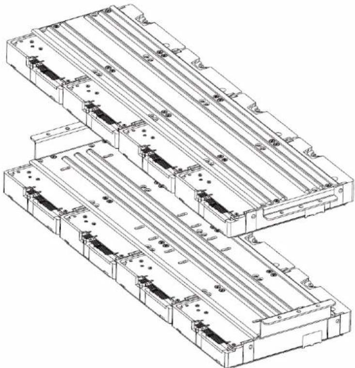
Technical line drawing of a multi-layered electronic component or enclosure with mounting holes and internal compartments (no text or symbols)Step 6 Repeat step 5 to install HDDs on the other holder.
Figure 3-7 Install HDD (3)
natural_image
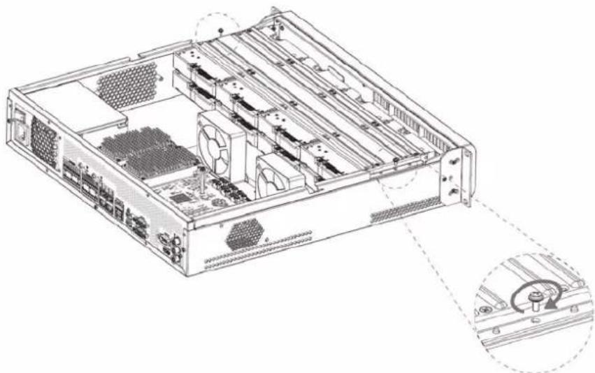
Technical line drawing of a multi-layered electrical enclosure or module assembly (no text or symbols)Step 7 Align the left and right 2 pairs of holes of the two holders to the corresponding holes on the chassis, place the holders on the chassis, and then tighten the screws on the edge of the holders.
Figure 3-8 Install HDD holders
natural_image
Technical line drawing of a server rack with visible internal components and mounting holes (no text or labels)Step 8 Connect HDD signal wire and power cord.
Step 9 Put back the cover, and then tighten the 2 screws on the rear panel.
3.3.2 12-HDD Series

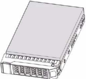
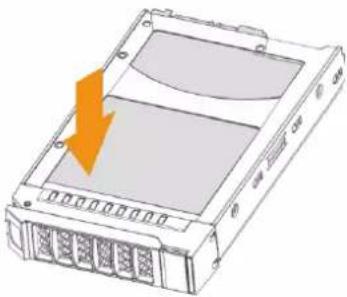
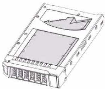
If you have not pushed the HDD box to the bottom, do not close the handle to avoid any damage to
the HDD slot.
Installing HDD
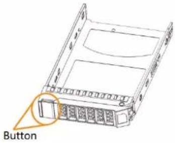 | 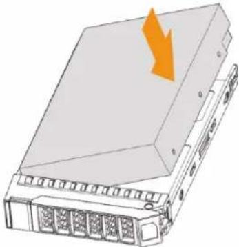 | 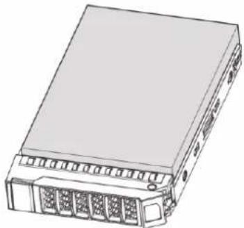 |
| 1Press the button on the front panel of IVSS, open the handle, and then pull out the HDD box. | 2Place one side of the HDD closely along the upper side of the box and press down to push the HDD down to the lower side of the mounting surface. | 3Insert the HDD box into the HDD slot, press it to the bottom, and then close the box handle. |
Removing HDD
 |  |  |
| 1Press the button on the front panel of IVSS, open the handle, and then pull out the HDD box. | 2 On the back of the HDD box, press hard on the position indicated by the arrow. | 3 Take out the HDD and reinsert the box to the slot. Push it to the bottom and close the box handle. |
3.3.3 16/24-HDD Series

If you have not pushed the HDD box to the bottom, do not close the handle to avoid any damage to the HDD slot.
Installing HDD
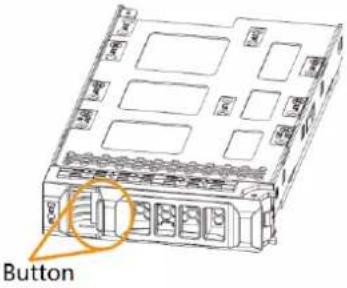 | 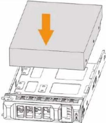 | 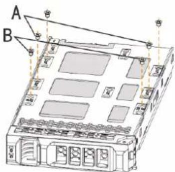 |
| 1Press the button on the front panel of IVSS, open the handle, and then pull out the HDD box. | 2Put the HDD into the box along the direction shown in the figure. | 3Lock the screws on the back of the HDD box. Insert the box into the HDD slot, push it to the bottom, and then close the handle.In the figure, you only need to lock one set of the screws (Group A or Group B). See the actual situation. |
Removing HDD
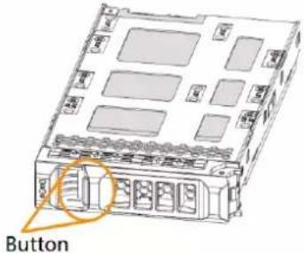 | 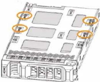 | 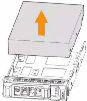 |
| 1Press the button on the front panel of IVSS, open the handle, and then pull out the HDD box. | 2Unlock the screws on the back of the HDD box.The screws are at different positions for different HDDs. | 3Take out the HDD and reinsert the box to the slot.Push it to the bottom and close the box handle. |
3.4 Cable Connection
The section introduces cable connection of the Device.
3.4.1 Alarm Connection
Before using the alarm, connect alarm input or alarm output device.
3.4.1.1 Connection
The section introduces alarm connection of the Device.
Alarm Input
- Both NO and NC are supported.
- The alarm input port supports alarm signal from ground and device of 12-24 V voltage.
- If the alarm device is connected to the Device and other devices, use relay for isolation.
Alarm Output
The alarm output port cannot be connected to high-power load (less than 1A). When forming output circuit, the excessive current should be prevented from causing damage to the relay. Use the contactor for isolation when applying high-power loads.
PTZ Decoder Connection
- The common-ground must be prepared for PTZ decoder and the Device; otherwise the common-mode voltage might not be able to control the PTZ. It is recommended to use shielded twisted pair, and the shielding layer can be used for common ground.
- Prevent interference from high-voltage power, make reasonable wiring, and take measures for lighting protection.
- Remotely import 120 to reduce resistance reflection and protect the signal quality.
- The Device A line and B line cannot connect to other RS-485 output device in parallel.
- The voltage between the A line and B line of PTZ decoder must be less than 5 V.
Notes to Grounding
- Poor grounding of camera might damage the chip.
- When supplying external power source to the alarm device, the alarm device should be common-grounded with the Device.
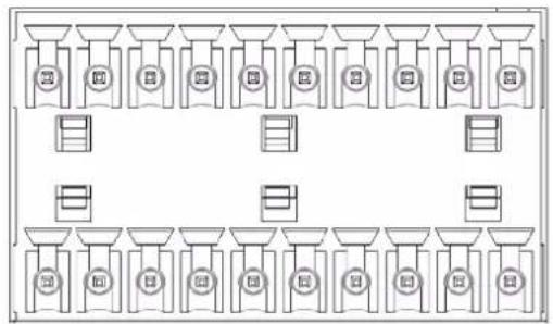
3.4.1.2 Alarm Port
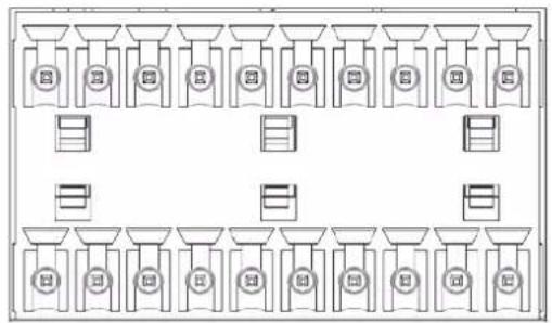
Figure 3-9 8-HDD series
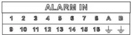
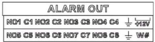
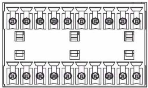
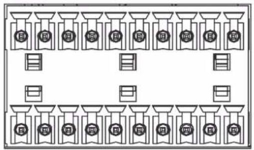
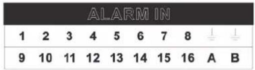
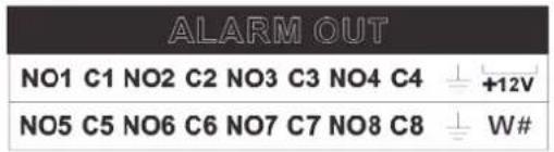
Figure 3-10 12-HDD series
flowchart
graph TD
    A["Department 1"] --> B["Department 2"]
    B --> C["Department 3"]
    C --> D["Department 4"]
    D --> E["Department 5"]
    E --> F["Department 6"]
    F --> G["Department 7"]
    G --> H["Department 8"]
    H --> I["Department 9"]
    I --> J["Department 10"]
    J --> K["Department 11"]
    K --> L["Department 12"]
    L --> M["Department 13"]
    M --> N["Department 14"]
    N --> O["Department 15"]
    O --> P["Department 16"]
    P --> Q["Department 17"]
    Q --> R["Department 18"]
    R --> S["Department 19"]
    S --> T["Department 20"]
flowchart
graph TD
    A["Department 1"] --> B["Department 2"]
    B --> C["Department 3"]
    C --> D["Department 4"]
    D --> E["Department 5"]
    E --> F["Department 6"]
    F --> G["Department 7"]
    G --> H["Department 8"]
    H --> I["Department 9"]
    I --> J["Department 10"]
    J --> K["Department 11"]
    K --> L["Department 12"]
    L --> M["Department 13"]
    M --> N["Department 14"]
    N --> O["Department 15"]
    O --> P["Department 16"]
    P --> Q["Department 17"]
    Q --> R["Department 18"]
    R --> S["Department 19"]
    S --> T["Department 20"]
Figure 3-11 16/24-HDD series (1)
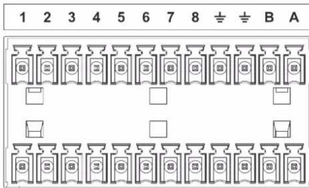
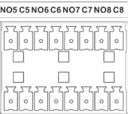

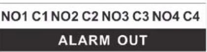
Figure 3-12 16/24-HDD series (2)
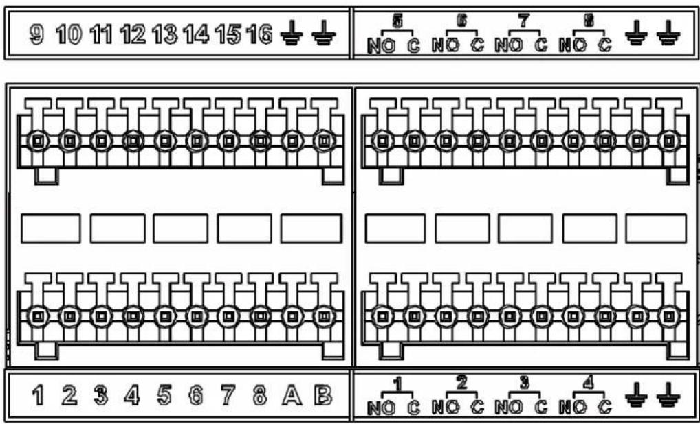
Table 3-2 Alarm port
| Icon | Description |
| 1–16 | They are corresponding to ALARM 1–ALARM 16. The alarm becomes valid in low level. |
| NO1 C1–NO8 C8 | Eight groups of normally open linkage output (on-off value). |
| +12V | Constant power output, 500mA current. |
| ± | Grounding wire. |
| A, B | A and B: Control the A/B cable of the RS–485 device. It is used to connect to the PTZ camera. Please parallel connect 120Ω between A/B cables if there are too many PTZ decoders. |
3.4.1.3 Alarm Input
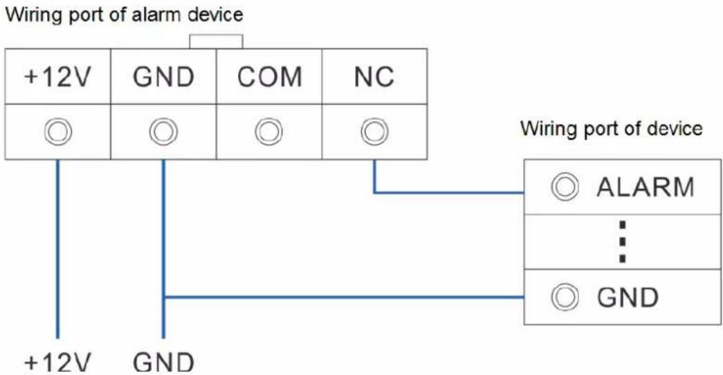
Both NO and NC are supported. For connection of NC alarm input port, see the following figures.
- GND and COM of alarm device shall be connected in parallel. Alarm device shall be powered with external power source.
- Connect GND of alarm device with GND of Device in parallel.
- Connect the NC port of alarm device to the alarm input port (1–16).
Figure 3-13 NC alarm input connection
flowchart
graph TD
    A["+12V"] --> B["GND"]
    B --> C["COM"]
    C --> D["NC"]
    E["+12V"] --> F["GND"]
    F --> G["ALARM"]
    H["Wiring port of device"] --> I["ALARM"]
    H --> J["GND"]
3.4.1.4 Alarm Output
- The alarm output is on-off output (Normally Open Contact), and there should be external power supply to alarm output device.
- RS-485 A line and B line: connecting the A line and B line on the PTZ decoder.
- To avoid overload from damaging the Device, see the parameters about relay.
Table 3-3 Relay parameters of alarm output port
| Model | HRB1-S-DC5V | ||
| Contact material Silver | |||
| Rated value (resistance load) | Rated power capacity | 24 VDC 2A, 125 VAC 2A | |
| Maximum power | 62.5 VA/30 W | ||
| Maximum power voltage | 125 VAC, 60 VDC | ||
| Maximum power current | 2 A | ||
| Insulation | Between contacts | 1000 VAC 1 minute | |
| Between contact and loop | 400 VAC 1 minute | ||
| Insulation voltage | 1,000 MΩ (500 VDC) | ||
| Turn-on Time < 5 ms | |||
| Turn-off Time < 5 ms | |||
| Life | Mechanical 300 times per minute | ||
| Electrical 30 times per minute | |||
| Model | HRB1-S-DC5V |
| Operating ambient temperature | -30 °C to +70 °C |
3.4.2 Connection Diagram

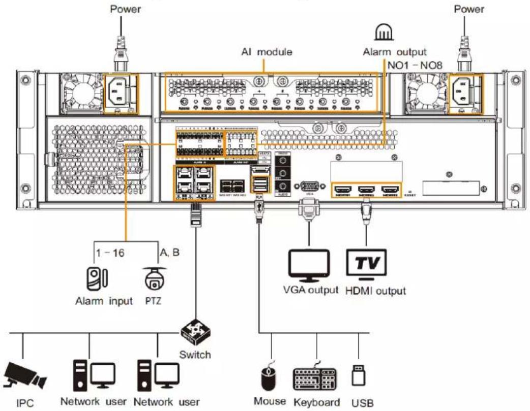
The following steps are to connect 16-HDD series device. See the actual product for detailed information.
The following figure is for reference only. The actual product shall prevail.
- Display, mouse and keyboard are needed for local operation.
- Before using the smart detection functions such as face detection and face recognition, you shall install the AI module first.
Figure 3-14 Connection diagram
4 Starting the Device

- Before starting the device, make sure that the input voltage shall match the device power requirement.
- To ensure stable operation of the device and prolong service life of HDD, provide stable voltage with less ripple interference by reference to international standard.
- For device security, connect other cables of the device first, and then connect the device to the power socket.
Boot-up might be different depending on the model you purchased.
- 8-HDD series: Press the power button on the rear panel to start the Device.
- For other series:
◇ Connect to the power socket to start the Device.
After clicking shutdown button on the GUI to shut down the Device, press the power button for a short period of time to start the Device.
5 Initial Settings
When using the Device for the first time, initialize the device, and set basic information and functions first.
5.1 Initializing Device
If it is your first time to use the device after purchasing or after restoring factory defaults, set a login password of admin (system default user). At the same time, you can set proper password protection method.

Take web remote initialization for example.
Step 1 Open the browser, enter IP address, and then press Enter.

Default IP address of network port 1 to network port 4 are 192.168.1.108 to 192.168.4.108. Enter the corresponding IP address of the actually connected network port.
Step 2 On the Language Set page, select a country or region, a language, and a language standard. Click Next. The language setting step is only available on the local interface of the Device.
Figure 5-1 Time setting
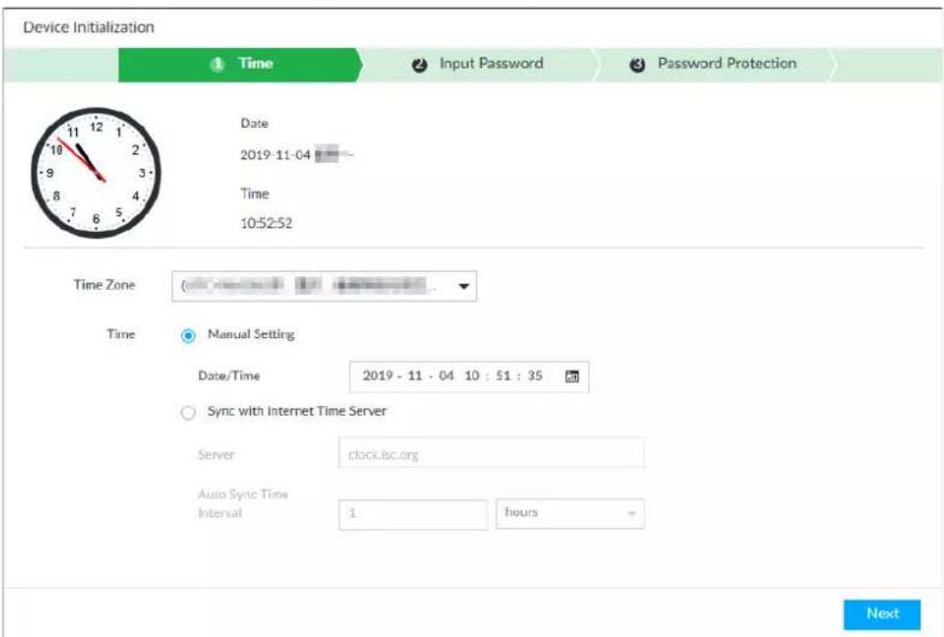
Step 3 On the Time page, set time parameters.
Table 5-1 Time parameters description
| Parameters | Description |
| Time Zone | The time zone of the Device. |
| Time | Set system date and time manually or by synchronizing with NTP server time.Manual Setting: Select date and time from the calendar.Sync with Internet Time Server: Select Sync with Internet Time Server, enter NTP server IP address or domain, and then set the automatic synchronization interval.Device time will synchronize with the server time after Sync with Internet Time Server is set. |
Step 4 Click Next.
Figure 5-2 Set password
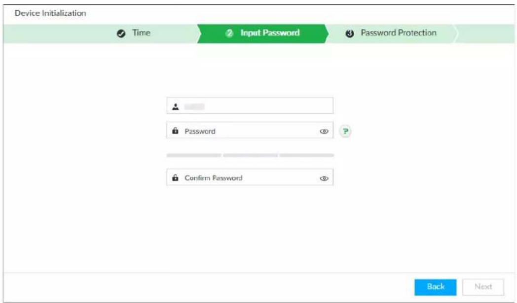
Step 5 Set admin login password.
Table 5-2 Description of password parameters
| Parameters | Description |
| Username The default username is admin. | |
| Password | Set admin login password, and confirm the password.The new password can be 8 characters to 32 characters in length and contains at least two types from number, letter and special characters (excluding "";& and space). Enter a strong password according to the password strength indication. |
| Confirm Password | |
Step 6 Click Next.
Figure 5-3 Password protection
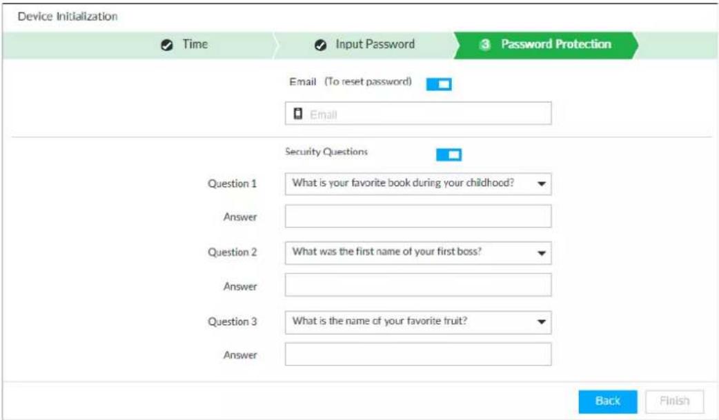
Step 7 Set password protection information.
You can use the email you input here or answer the security questions to reset admin password. See "8.7.3.2 Resetting Password" for detailed information.

- Click to cancel the email or security questions.
- If the email is not set, the password can be reset on the local interface only.
Table 5-3 Password protection
| Password protection mode | Description |
| Leave an email address for resetting password. | |
| Security question | Set security questions and corresponding answers. Reset the password through the security question. |
Step 8 Click Finish to complete device initialization.
5.2 Quick Settings
After initializing the device, the system goes to quick settings page. You can quickly set system time, IP address, and P2P.
5.2.1 Configuring IP Address
Configure device IP address, DNS server information and other information according to network planning.

Device has 4 Ethernet ports by default. Make sure that at least one Ethernet port has been connected to the network before you set IP address.
Step 1 On the completion page of initialization, click Enter Quick Setting.
Figure 5-4 IP setting
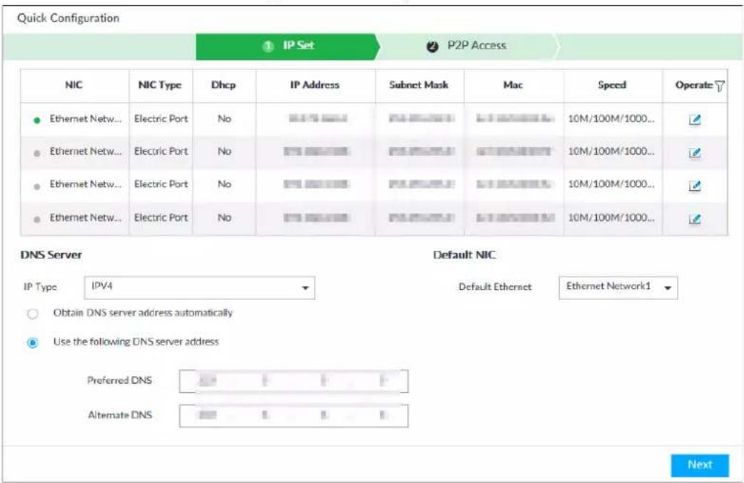
Step 2 Configure IP address.
1) Click ☐ of the corresponding NIC.
Figure 5-5 Edit Ethernet network
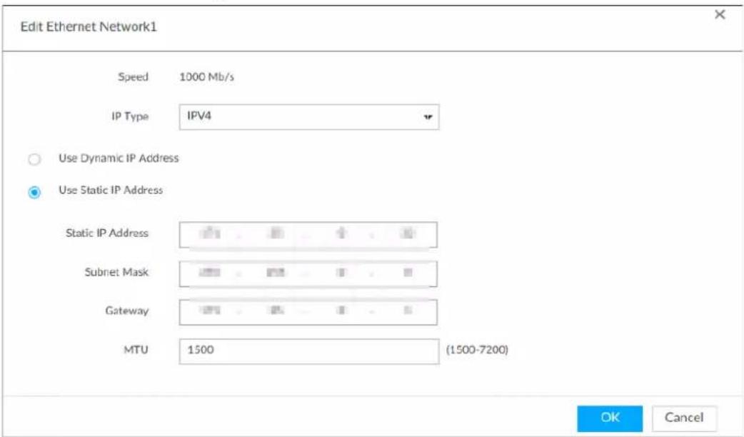
2) Set parameters.
Table 5-4 TCP/IP parameters description
| Parameters | Description |
| Speed | Current NIC max network transmission speed. |
| IP Type Select IPv4 or IPv6. | |
| Use dynamic IP address | When there is a DHCP server on the network, checkUse Dynamic IP Address, system can allocate a dynamic IP address to the device. There is no need to set IP address manually. |
| Use static IP address | Check Use Static IP Address, and then set static IP address, subnet mask and gateway to set a static IP address for the device. |
| MTU | Set NIC MTU value. The default setup is 1500 Byte.We recommend you to check the MTU value of the gateway first and then set the device MTU value equal to or smaller than the gateway value. It is to reduce the packets slightly and enhance network transmission efficiency. Please be advised that changing MTU value might result in NIC reboot, network offline and affect current running operation. Please be advised that changing MTU value might result in NIC reboot, network offline and affect current running operation. |
3) Click OK.
Device goes back to IP Set page.
Step 3 Set DNS server information.
You can select to get DNS server manually or input DNS server information.

This step is compulsive if you want to use domain service.
1) Select an IP type for DNS server. You can select IPv4 or IPv6.
2) Select the way of setting DNS IP address.
Step 4 Set default NIC.
Select default NIC from the drop-down list.

Make sure that the default NIC is online.
Step 5 Click Next to save settings.
5.2.2 Configuring P2P Settings
P2P is a peer to peer technology. You can scan the QR code to download cellphone APP without DDNS service or the port mapping or installing the transmission server. After register the device to the APP, you can view the remote video, playback record file and so on.

Make sure that the system has been connected to the network. Otherwise, the P2P function is null.
Step 1 On IP Set page, click Next, and then scan the QR code on the actual page.
Figure 5-6 P2P access
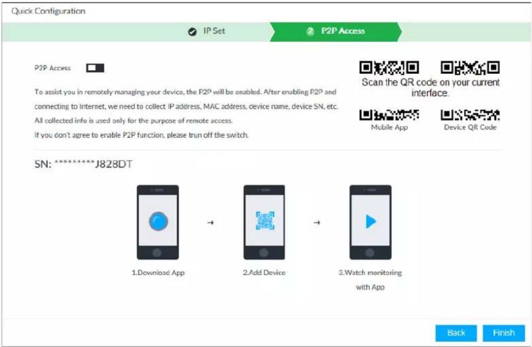
Step 2 Click □ to enable P2P function. The function is disabled by default.
Step 3 Click Finish to save settings.
After the configuration, you can register a device to the APP to view remote video, playback record file, and so on. See corresponding cellphone APP for detailed information.
5.3 Login
You can operate the device by using the local interface, web client and PCAPP.
- Monitor and mouse are needed for local operation.
- Remotely access with web and IPCAPP. PCAPP client is recommended.

After initializing the device, you have logged in by default. Now you can set system settings and operate.
5.3.1 Logging in to PCAPP Client
Log in to PCAPP for system configuration and operation.
Step 1 Download PCAPP.
1) Open the browser, enter IP address, and press Enter.
2) Click Download PCAPP to download PCAPP installation package.
Step 2 Install PCAPP.
1) Double-click the installation package.
2) Select a language of PCAPP.
3) Click EULA, read through the content, and then select the checkbox of I Agree EULA.
4) (Optional) Select installation path, click Custom, and then select a path.
5) Click Install.
Step 3 Log in to PCAPP.
1) There are two ways to enter PCAPP.
- On the installation completion page, click Run.
- Double-click the shortcut icon on the PC desktop.

- When PC theme is not Aero, the system will remind you to switch the theme. To ensure video smoothness, switch your PC to Areo theme. For details, see "10.4 Configuring PCAPP".
- System displays PCAPP at full-screen by default. Click to display the task column.
Figure 5-7 Prompt
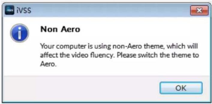
Figure 5-8 Task column

2) Enter device IP address, and then press Enter or click →.
3) Enter device username and password.

- Click Login. For your device safety, change the admin password regularly and keep it well.
- In case you forgot password, click Forgot password to reset.
4) Select the login type among TCP, UDP and Multicast. Keep it as TCP if you have no special requirement for TCP or UDP.
5) Click Login.
Figure 5-9 Live view
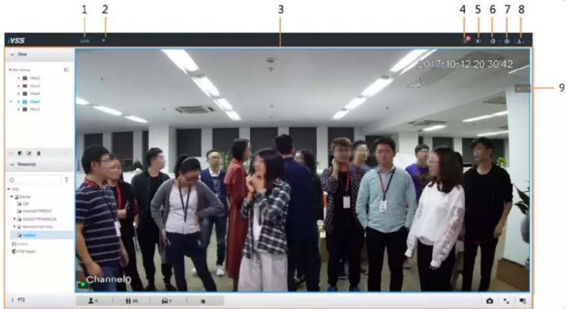
Table 5-5 Home page description
| No. | Name | Description |
| 1 Task column | Displays enabled application icon.Point to the app and then click ✗ to close the app.The live function is enabled by default and cannot be closed. | |
| 2 Add icon | Click to display or hide the APPLICATIONS window. On the APPLICATIONS window to view or enable app. | |
| 3 | Operation page | Displays currently enabled app operation page. |
| 4 | System Info | Click to view system information. |
| 5 | Buzzer | Click the icon to view buzzer messages. |
| 6 | Background Task | Click to view the background running task information. |
| 7 | System config | Click to enter system configuration mode. |
| 8 Login user | Click it to change user password, lock user, logout user,reboot device or close device. | |
| 9 Alarm list | Click to view the unprocessed alarm event quantity.Drag this icon to move its position. | |
5.3.2 Logging in to Local Interface
You can view the local interface of the Device by connecting a display to it, and then you can carry out local operation on the display.
5.3.2.1 Preparation
Ensure that the Device is connected with display, mouse and keyboard. For cable connection, see "3.4 Cable Connection".
5.3.2.2 Operation Steps
Step 1 Turn on the Device.
Step 2 Enter username and password.

- Click Login. For your device safety, change the admin password regularly and keep it well.
- Point to ⓘ to view the password prompt information. It is to help you remember password.
- In case you forgot password, click Forgot Password to reset. See "8.7.3.2 Resetting Password".
Step 3 Click Login.

Click 📁 to control the local screen. See "7.7.1 Multiple-screen Control" for detailed information.
5.3.3 Logging in to Web Interface
System supports general browser such as Google Chrome, Firefox to access the web to manage the device remotely, operate and maintain the system.

When you are using general browser to access the web, system supports setting function only. It cannot display the view. It is suggested that PCAPP should be used.
Step 1 Open the browser, input IP address, and press Enter.
Step 2 Enter username and password.

- Click Login. For your device safety, change the admin password regularly and keep it well.
- In case you forgot password, click Forgot Password to reset. See "8.7.3.2 Resetting Password" for detailed information.
Step 3 Select the login type among TCP, UDP and Multicast. Keep it as TCP if you have no special requirement for TCP or UDP.
Step 4 Click Login.
System displays LIVE page.
5.4 Configuring Remote Device
Register remote device to the system. You can view the live video from the remote device, change remote device settings, and so on.
5.4.1 Initializing Remote Device
After you initialize the remote device, you can change remote device login password and IP address. Remote devices can be connected to the Device only after being initialized.
Step 1 Click 🎨, or click + on the configuration page, and then select DEVICE.
Step 2 On the Device List page, click Add.
Step 3 On the Smart Add page, click Smart Search.
The search results are displayed.

To set search conditions, you can click .
Step 4 Select the uninitialized remote device and then click Initialize button.

Click Initialization status and then select Uninitialized, you can quickly filter the uninitialized remote device.
Figure 5-10 Initialize the device
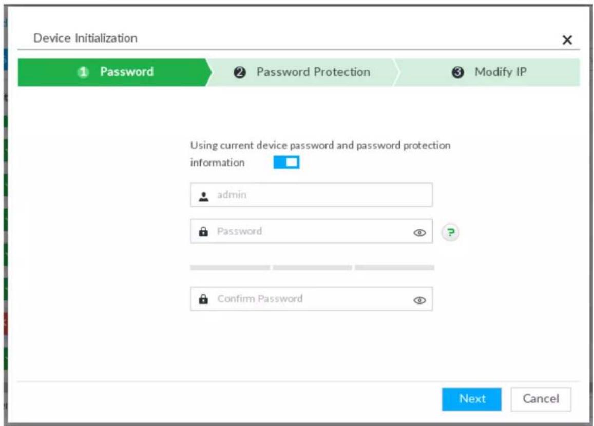
Step 5 Set remote device password and password protection.

Using current device password and password protection information is enabled by default. Keep it enabled so as to automatically use current device admin password and email without manual configuration. Go to Step 6 if you keep it enabled.
1) To manually configure password, click ☐ to disable Using current device password and password protection information.
Figure 5-11 Password setting
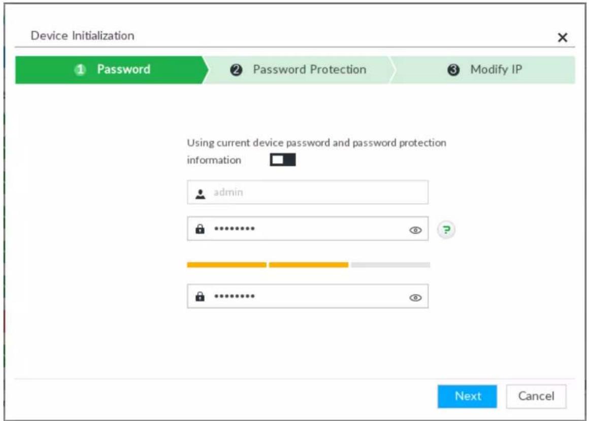
2) Set parameters.
Table 5-6 Description of password parameters
| Parameters | Description |
| Username The default username is admin. | |
| Password In the | New Password box, enter the new password and enter it again in the Confirm Password box.The new password can be set from 8 characters through 32 characters and contains at least two types from number, letter and special characters (excluding "";& and space). Enter a strong password according to the password strength indication. |
| Confirm Password | |
3) Click Next.
Figure 5-12 Password protection
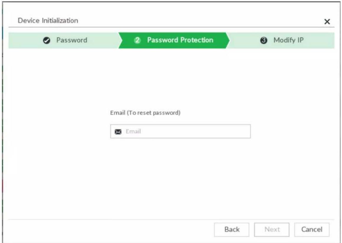
4) Set an email address.
Enter an email address. You can use the email address here to reset password in case you forgot password in the future.
Step 6 Click Next button.
Figure 5-13 Modify IP
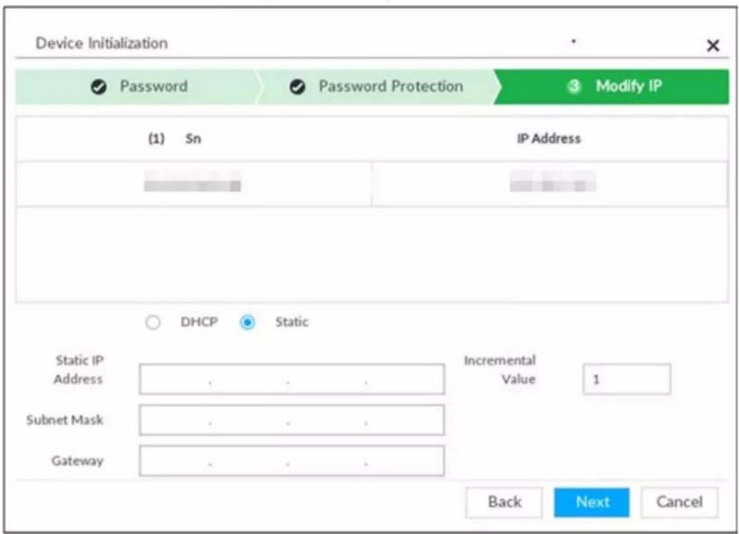
Step 7 Set camera IP address.
- When there is DHCP server in the network, select DHCP, and the remote device gets dynamic IP address automatically. It is unnecessary to enter IP address, subnet mask and gateway.
- Select Static, and then enter static IP address, subnet mask, default gateway and incremental value.

- After you input incremental value, system can add the fourth address of the IP address one by one to automatically allocate the IP addresses.
- If you want to change several devices IP addresses at the same time, system allocates IP address of the same network segment.
- If there is IP conflict when changing static IP address, device pops up IP conflict dialogue box. If batch change IP address, device automatically skips the conflicted IP and begins the allocation according to the incremental value.
Step 8 Click Next.
System begins initializing remote device.
Figure 5-14 Initialize
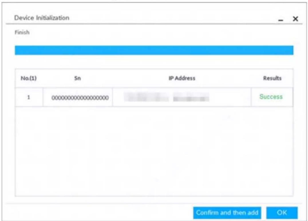
Step 9 Click Confirm and Add, or click OK.
- Click Confirm and Add: System completes initializing the remote device and then adds the remote device to the list. System goes back to Add device page.
- Click OK: System completes initializing remote device. System goes back to Add device page.
5.4.2 Adding Remote Device
Device supports smart add, manual add and template add.
Table 5-7 Add mode
| Add Mode | Description |
| Smart Add | Search the remote devices on the same network and then filter to register. For details, see "5.4.2.1 Smart Add".It is useful if you do not know the exact IP address. |
| Manual Add | Enter the IP address, username and password of remote device. For details, see "5.4.2.2 Manual Add".For some remote devices, you can enter IP address, username, and password to register. |
| RTSP | Add remote devices through RTSP. For details, see "5.4.2.3 RTSP".To add stream media devices, you are recommended to choose RTSP. |
| Batch add (by CSV template) | Fill in information about remote device in the template, import the template to add the device. For details, see "5.4.2.4 Batch Add".For batch adding, when IP address, username and other information of remote device is inconsistent, it is suggested to use this mode. |
5.4.2.1 Smart Add
Step 1 Click 🔍 and then select DEVICE.
The DEVICE page is displayed.
Step 2 Click + or Add, and then select Smart Add.
Figure 5-15 Smart add
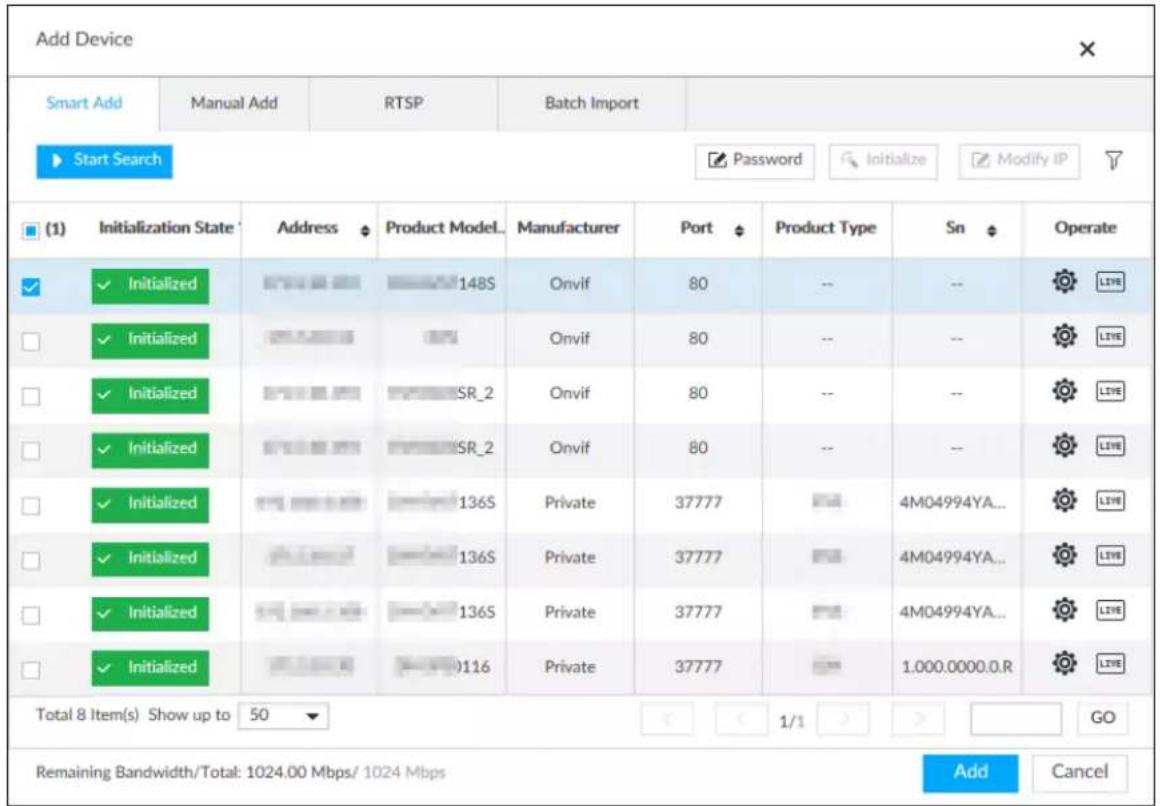
Step 3 Click Start Search.

To set search conditions, you can click .
Figure 5-16 Search results
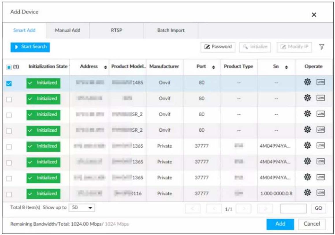
Table 5-8 Result description
| Parameters | Description |
| Start Search | Click Start Search to start searching remote device. Now it becomesStop Search button. ClickStop Search button to stop searching remote device. |
| Password | Enter the username and password of the selected device for adding it. |
| Initialize | Select uninitialized remote device and then clickInitialize button to initialize remote device. See "5.4.1 Initializing Remote Device". For detailed information. |
| Modify IP | See "8.2.2.2 Changing IP Address" to change the registered device IP address. |
| Initialization State | Displays remote device initialization status.Click ▼ to filter initialized or uninitialized remote device. |
| Operation | Clickto set related parameters. For details, see Table 5-9.ClickLIVeto display real-time video from the remote device. Clickor Close to close the real-time preview window. You can view the live video if admin password of the remote device is admin, or remote device admin password is the same as the system. You can view the live video if admin password of the remote device is admin, or remote device admin password is the same as the system. |
| Bandwidth | Displays bandwidth remaining and the total bandwidth. |
Figure 5-17 Live view
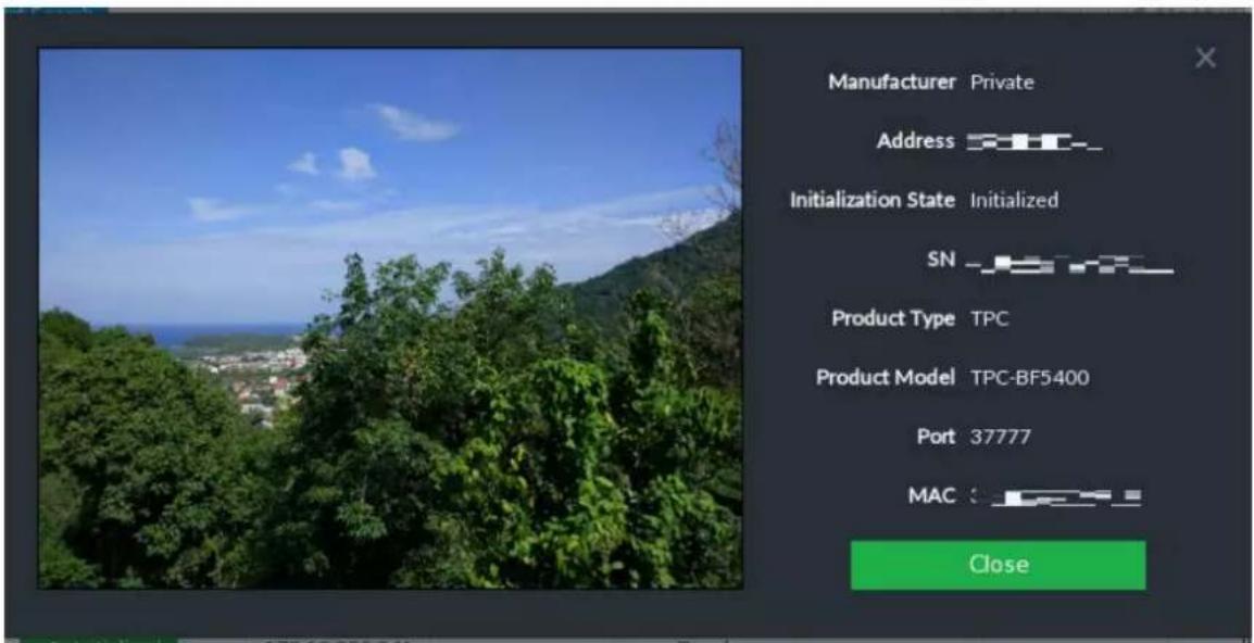
Step 4 Adding a remote device.
Select a remote device, click Password, and then enter the username and password of the selected device. Click OK.

- If you do not enter device username and password, the system will try to add the device by using the username and password of the Device.
- During the adding process, click Cancel button, you can cancel adding process. Click Stop button of the corresponding remote device to cancel add.
Step 5 Click Add.

- Click remote device IP address, username, password, SN, channel and port to change corresponding information.
- If system fails to add the remote device, see the reason on the Status column to change the remote device information and then click Retry to try to add again.
- If a remote device is in exception due to network disconnection other reasons, it can also be added. It comes online after the exception is resolved.
Step 6 Click Continue to add or Finish.
- Click Continue to add, device goes back to the Smart Add page to add more remote device.
- Click Finish to complete adding remote device process. You can view the newly added remote device information on the device list.
5.4.2.2 Manual Add
Step 1 Click 🔍, and then select DEVICE.
Step 2 Click + and then select Manual add.
Step 3 Click Add Device.
Figure 5-18 Add device
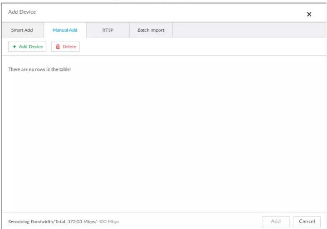
Step 4 Set parameters and then click OK.
Figure 5-19 Remote device setting
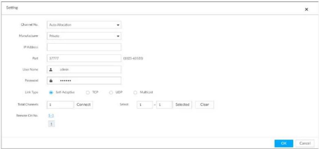
Table 5-9 Parameters of adding device
| Parameters | Description |
| Channel No. | Select a channel number for the remote device on IVSS.If you select Auto Allocation, IVSS will provide a channel number automatically. |
| Manufacturer | Displays the connection protocol of the remote device. Default protocol of the system is Private. Click Private to select other protocols. |
| IP Address | Enter the IP address of the remote device. |
| Device SN | Enter the unique SN allocated by the server for the remote device. When the Manufacturer is Register, you need to configure this parameter. When the Manufacturer is Register, you need to configure this parameter. |
| RTSP Port | Enter the RTSP port number. The default port number is 554. The value ranges from 1 through 65535. |
| RTSP Mode | Select Self-adaptive or Customize. When the Manufacturer is Onvif or Onvifs, you need to configure this parameter. When the Manufacturer is Onvif or Onvifs, you need to configure this parameter. |
| HTTP Port | Enter the HTTP port number. The default port number is 80. The value ranges from 1 through 65535. After changing the HTTP port number, you need to add the HTTP port number to the IP address in the address bar of the browser for login. |
| HTTPS Port | Enter the HTTP port number. The default port number is 80. The value ranges from 1 through 65535. When the Manufacturer is Onvifs, you need to configure this parameter. When the Manufacturer is Onvifs, you need to configure this parameter. |
| User Name | Enter the username and password of the remote device. |
| Password | |
| Port | Enter the port number of the remote device.When the Manufacturer is Private, you need to configure this parameter. |
| Remote CH No. | Select the channel number for the remote device.Select a link type.To get the total number of channels, click Connect.Enter the range of channels you need, and then click Selected.Click OK. |
Step 5 Select the remote device and then click Add.

- If system fails to add the remote device, see the reason on the Status column to change the remote device information and then click Retry to try to add again.
- If a remote device is in exception due to network disconnection other reasons, it can also be added. It comes online after the exception is resolved.
Figure 5-20 Confirm
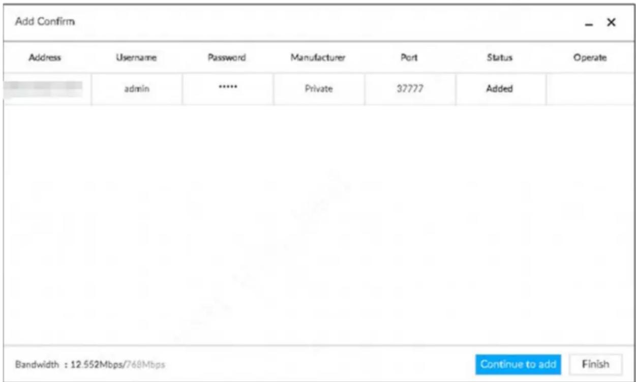
Step 6 Click Continue to add or Finish.
- Click Continue to add, device goes back to Smart add page to add more remote device.
- Click Finish to complete adding remote device process. Device displays Device page to view the newly added remote device information.
5.4.2.3 RTSP
Step 1 Click 🔍, and then select DEVICE.
Step 2 On the Device List page, click Add.
The Add Device page is displayed.
Step 3 Click RTSP.
Step 4 Enter RTSP address as required.
RTSP address format is rtsp://
- Username: Username of the remote device.
- Password: Password of the remote device.
- IP address: IP address of the remote device.
- Port: 554 by default.
- Channel: The channel number of the stream media device to be added.
- Subtype: Stream type. 0 for main stream, and 1 for sub stream.
Step 5 Select a channel No.
Step 6 Click Add.
5.4.2.4 Batch Add
Step 1 Click 🔍, and then select DEVICE.
Step 2 Click +, and then click the Batch Import tab.
Figure 5-21 Import CSV file
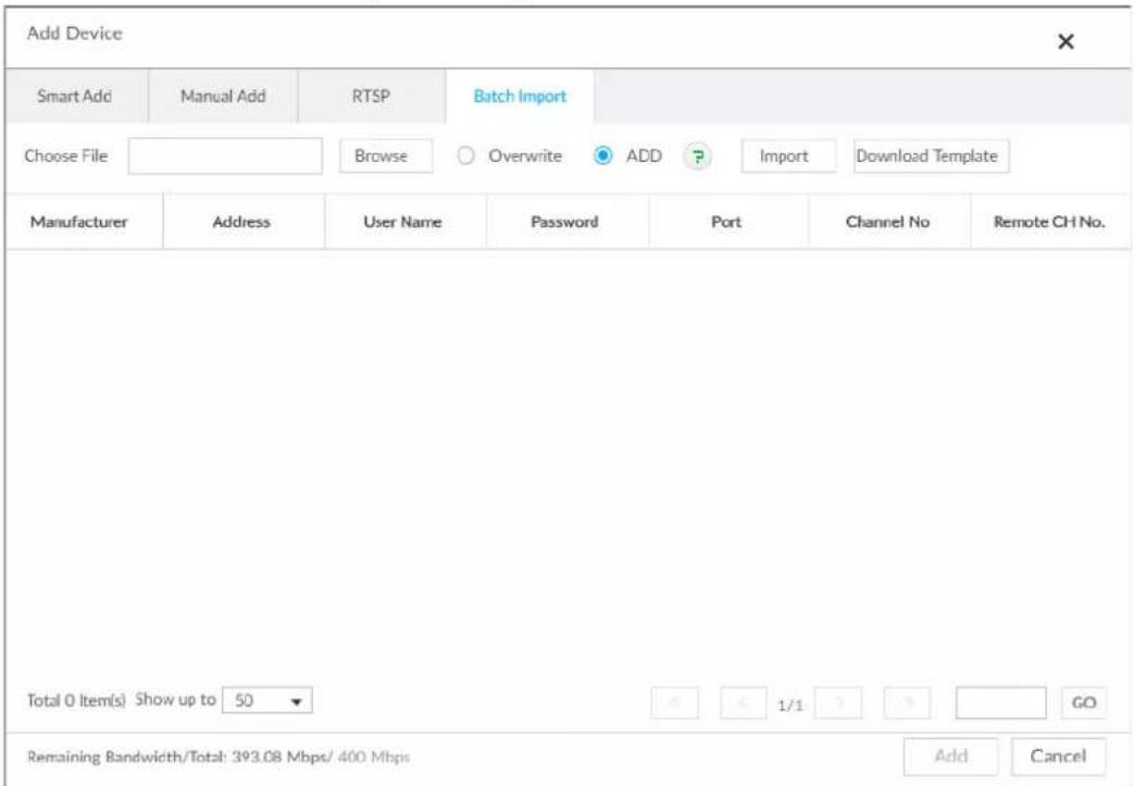
Step 3 Fill in template file.
1) Click Download Template to download template file.
File path might vary depending on your operations.
- At PCAPP, click, select Download to view file saving path.
- During local operation, you can select file saving path.
- During web operations, files are saved under default downloading path of the browser.
2) Fill in and save the template file.
Step 4 Import template file.
1) Click Browse to select the file that you have filled in.
2) Select an import mode and then click Import.
- Overwrite: The system removes the added remote devices before importing new devices.

If you select Overwrite, all the existing devices will be deleted.
- ADD: The system imports remote devices without deleting the existing ones.
Figure 5-22 Batch import
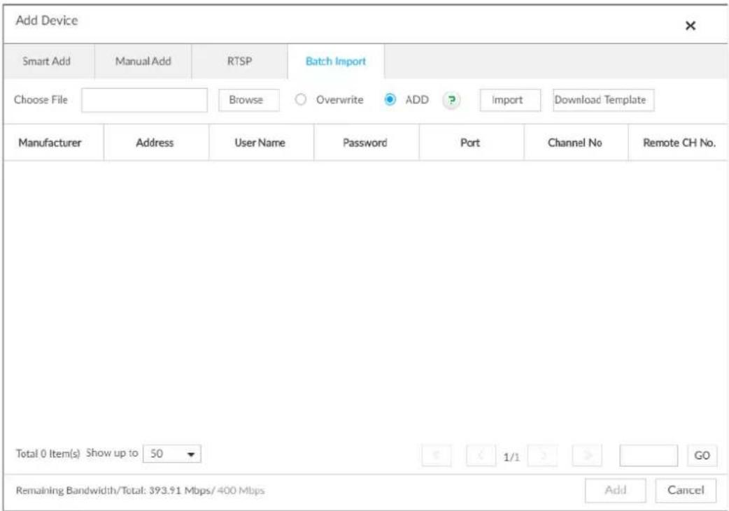
Step 5 Select the remote device and then click Add.

- If information about remote device is not filled in completely, improve it after importing template.
- If the system fails to add the remote device, check the reason on the Status column, change the remote device information and then click Retry to try to add again.
Figure 5-23 Confirm
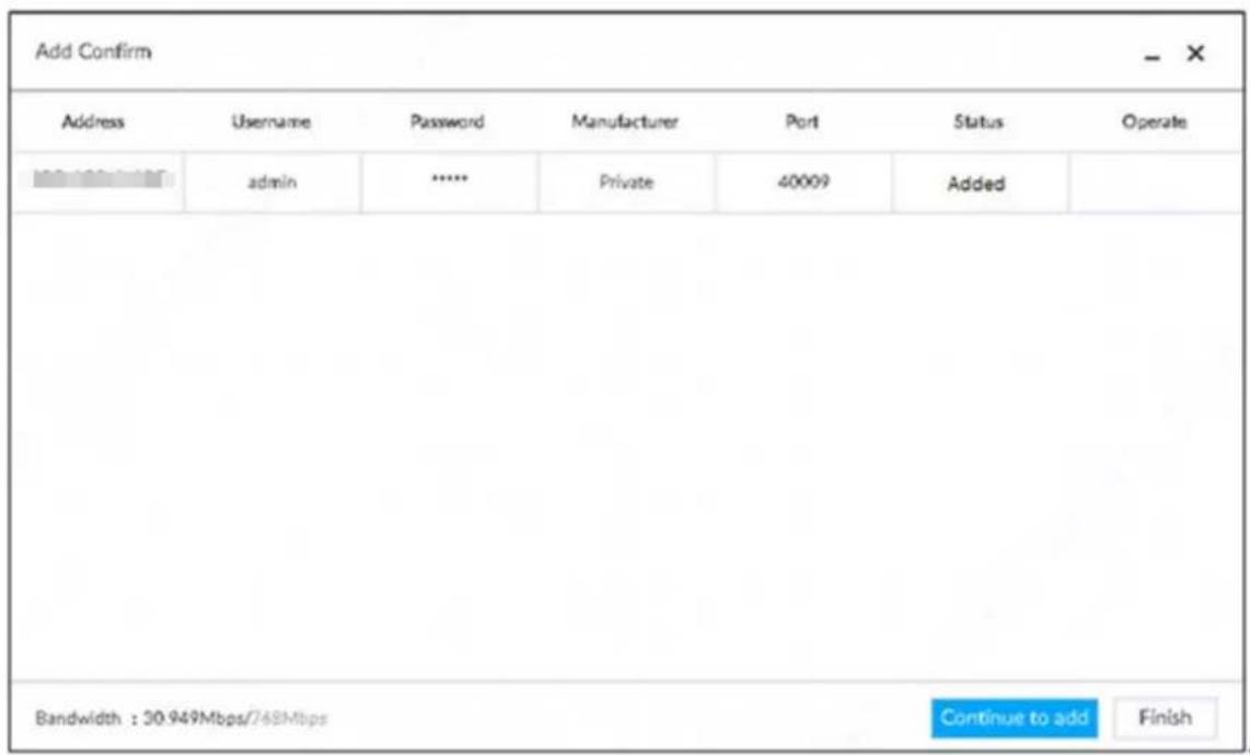
Step 6 Click Continue to add or Finish.
- Click Continue to add, device goes back to Smart add page to add more remote device.
- Click Finish to complete adding remote device process. Device displays Device manager page to view the newly added remote device information.
6 AI Operations
In addition to the basic video monitoring functions, the Device can also provide a number of AI functions including face recognition, people counting, video metadata, ANPR, and IVS (behavior detections such as fence-crossing, intrusion, loitering, crowd gathering, parking and more).
This chapter introduces how to configure the AI functions respectively.
The AI detections can be done by camera (AI by camera) or by IVSS (AI by device).
- AI by camera: When configuring an intelligent detection, if you select AI by camera, the intelligent analysis job is completed on the camera, and the Device just receives and processes the results.
- AI by device: When configuring an intelligent detection, if you select AI by device, the camera uploads video and snapshots, and then the Device is responsible for the video analysis job.

- The AI functions might vary depending on the device function capability.
- When AI by camera is enabled, complete AI detection configuration at remote device. See remote device user's manual.
- The AI by Camera tab does not appear if the current camera does not support this function.
6.1 Overview
Viewing Event Enabling Status
View the usage status of the AI functions of all remote devices.
Click 📋 at the upper-right corner of the homepage to open the Event page. The Overview page is displayed by default, which shows the usage status of the AI functions of all remote devices.
Figure 6-1 Overview
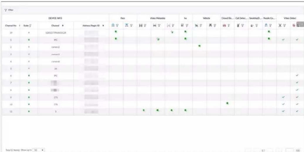

indicates that the AI by camera is enabled. indicates that AI by device is enabled.
AI Events by Device or Camera
Table 6-1 AI Events by Device or Camera
| AI Event | AI by Camera | AI by Device |
| Face Detection | Yes | Yes |
| Face Recognition Yes Yes | ||
| People Counting Yes No | ||
| Video Metadata | Yes | Yes |
| IVS Yes Yes | ||
| Crowd Distribution | Yes | No |
| Call Alarm Yes No | ||
| Smoking Alarm Yes No | ||
| Vehicle Recognition | Yes | No |
| Plate Comparison | No | Yes |
6.2 Face Detection
System triggers alarms when human faces are detected within the detection zone.
6.2.1 Enabling AI Plan
To use AI by camera, you need to enable AI plan first.

- AI plan is available on select models.
- The Device automatically shows the AI functions available on the connected cameras.
Step 1 Click 🎨 or click + on the configuration page, and then select EVENT. The EVENT page is displayed.
Step 2 Select a camera in the device tree on the left.
Step 3 Select AI Application > AI Plan > AI Plan.

- The page might vary depending on the function capabilities of cameras.
- When the camera is a PTZ camera, configure presets on the camera system first, and then you can set AI features for each preset of the PTZ camera.
Step 4 Click □ to enable AI detection plan. The icon becomes □.
When there is a conflict between the to-be-enabled AI plan and an enabled plan, disable the enabled plan first.
Step 5 Click Save.
6.2.2 Configuring Face Detection
Configure alarm rule of face detection.
Step 1 Click 🎨 or click + on the configuration page, and then select EVENT.
Step 2 Select a remote device in the device tree on the left.
Step 3 Select AI Plan > Face Detection.
Figure 6-2 AI by camera
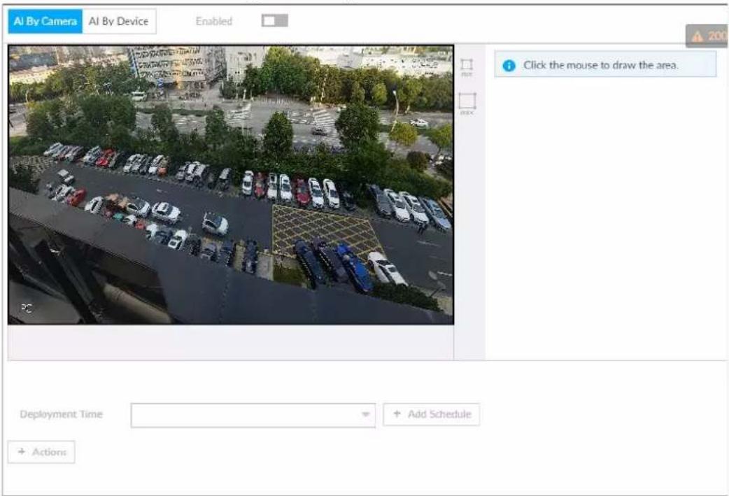
Figure 6-3 AI by device
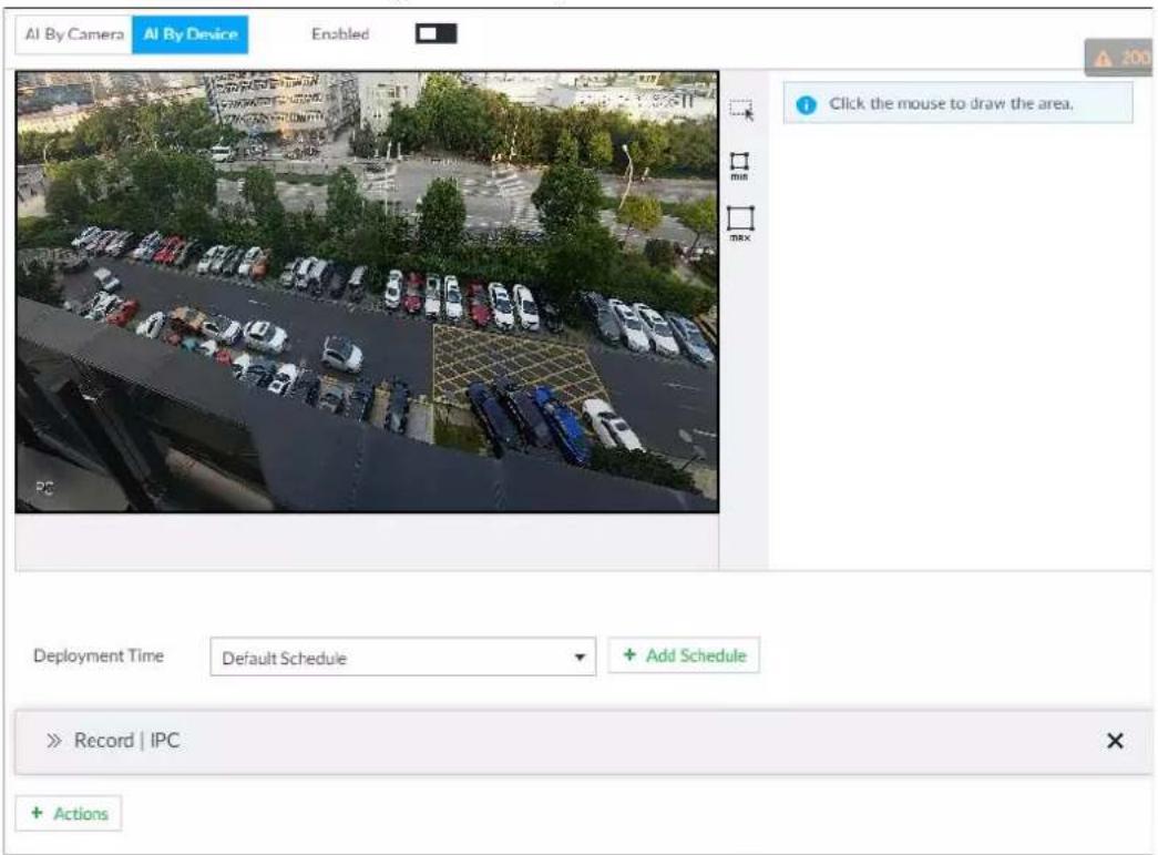
Step 4 Click AI by camera or AI by device, and then click □ to enable face detection.

AI by camera supports Face Enhancement. After enabling Face Enhancement, system displays enhanced human face zone on the surveillance window.
Step 5 Set detection area on the video (yellow area).
Figure 6-4 Area
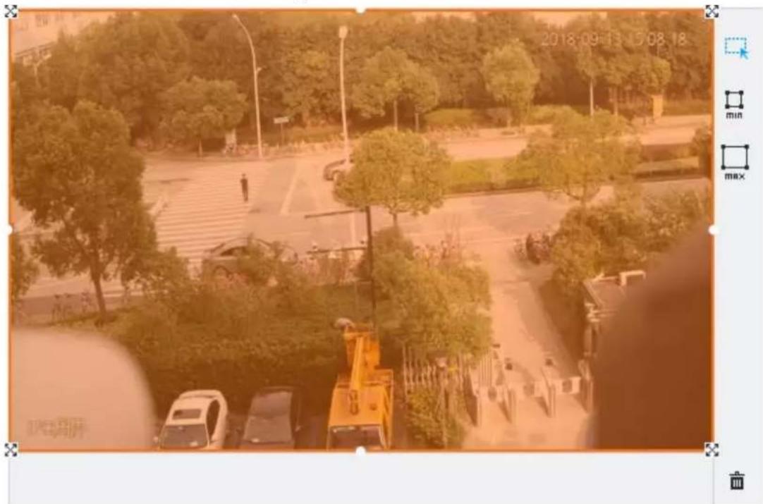
- Click ✗ or white dot on detect region frame, and drag to adjust its range.
- Click ☐ or ☐ to set the minimum size or maximum size of the face detection area. System triggers an alarm once the size of detected target is between the maximum size and the minimum size.
Step 6 Click Deployment Time to select a schedule from the drop-down list.
System triggers corresponding alarm actions only during the alarm deployment period.

You can select an existing schedule from the Deployment Time drop-down list. You can also add a new schedule. For details, see "8.8.4 Schedule".
Step 7 Click Action to set alarm action. See "8.4.1 Alarm Actions" for detailed information.
Step 8 Click Save.
6.2.3 Live View of Face Detection
You can view real-time face detection images and video.
6.2.3.1 Setting AI Display
You can configure display rule of face detection results.

Before using this function, ensure that view has been created. See "7.1.1 View Management" for detailed information.
Step 1 On the LIVE page, click ☑ and select the Face tab.

- Click Sync from AI-Dis., obtain global smart detection display rule of IVSS. See "8.4.2.4.2 Setting AI Display" for detailed information.
- Click Apply to all windows to copy current configuration to other window(s).
Figure 6-5 Face
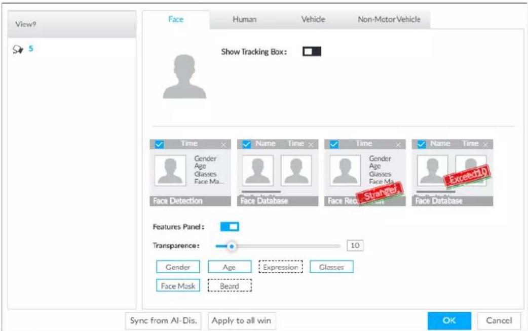
Step 2 Enable Show Tracking Boxby clicking □.
After it is enabled, when the system detects face or human, the window will display corresponding rule box.
Step 3 Enable Features Panel, and select feature(s) you want to display.
1) Click □ next to Features Panel, to enable the function. When the panel is enabled, the snapshots of detected faces are displayed on the live view.
2) Click ☐ to select Face Detection tab. ✅ indicates that the panel is selected.
3) (Optional) Drag ⚙ to adjust features panel transparency. The higher the value, the more transparent the features panel.
4) (Optional) Select the features you need to display.
- System supports displaying 4 feature types.
- System has checked four features by default. To select other features, cancel the selected features, and then select the ones you need.
Step 4 Click OK to save the configuration.
6.2.3.2 Live View
Go to the LIVE page, enable view, and then view videos are displayed.
- The view window displays currently detected face rule boxes.
- Features panels are displayed on the right side in real time.
- The features panel displays detection time, face snapshot and face features details.
Figure 6-6 Live
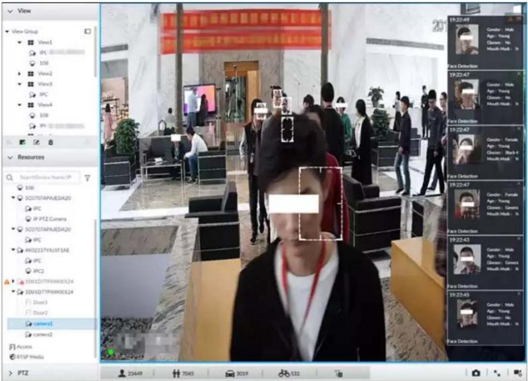
Point to a features panel, and the operation icons are displayed.
Figure 6-7 Face database
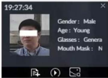
- Click ☑ to add this image to the face database. See "6.8.3.2.3 Adding from Detection Results" for detailed information.
- Click 📋 or double-click the detected image, so the system starts to play back the recorded videos (about 10s) at the time of snapshot.
- Click to open the Search by Face page where you can use this face image to search all history face records for the appearance records of the current face.
6.2.3.3 Face Records
On the LIVE page, click 🔒. The FACE TOTAL page is displayed. Click 🔒, and then select Face Detection. The latest face detection records are displayed.
Figure 6-8 Detection image
On the FACE TOTAL page, the following operations are available.
- Point to a piece of face record, click , and then you can quickly add this image to the face database. See "6.3.3.4.3 Adding Face Image" for detailed information.
- Point to a piece of face record, click or double-click the detected image, and then the system starts to play back the recorded videos (about 10s) at the time of snapshot.
- Point to a piece of face record, click , and then you can save that record locally including the video and pictures.
- Point to a piece of face record, click , and then the system automatically searches videos and face pictures of all channels for the similar face in the defined period.
6.2.4 Face Search
Search for face detection information, including face detection image, record and features.
6.2.4.1 Searching by Property
Step 1 On the LIVE page, click , and then select AI SEARCH > Search by Face > By Property.
Figure 6-9 Search by property
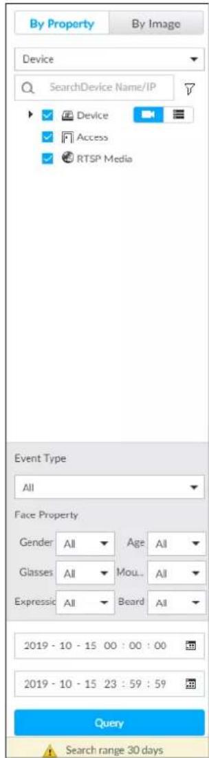
Step 2 Select a remote device, and then set Event Type to be Face Detection.
In the Event Type drop-down list, if you select All, the search results will include both face detection records and face recognition records.
Step 3 Set face property and time.
Step 4 Click Query.
The search results are displayed.
Figure 6-10 Search results
| AI 2019-10-15 | □ All(O) Export □ Total 26077 Recherds | |||||
| camera1 | 14:21:32 | camera1 | 14:21:39 | camera1 | 14:21:37 | |
| Gender: Female Age: Young Glasses: No Mouth Mask: No | Gender: Male Age: Young Glasses: No Mouth Mask: No | Gender: Male Age: Young Glasses: No Mouth Mask: No | ||||
| Face Detection | Face Detection | Face Detection | ||||
| camera1 | 14:22:27 | camera1 | 14:22:37 | camera1 | 14:23:02 | |
| Gender: Female Age: Young Glasses: No Mouth Mask: No | Gender: Male Age: Young Glasses: No Mouth Mask: No | Gender: Male Age: Middle-aged Glasses: No Mouth Mask: Yes | ||||
| Face Detection | Face Detection | Face Detection | ||||
| camera1 | 14:24:05 | camera1 | 14:25:23 | camera1 | 14:25:37 | |
| Gender: Male Age: Young Glasses: No Mouth Mask: No | Gender: Male Age: Middle-aged Glasses: No Mouth Mask: Yes | Gender: Male Age: Middle-aged Glasses: No Mouth Mask: No | ||||
| Face Detection | Face Detection | Face Detection | ||||
| camera1 | 14:25:44 | camera1 | 14:25:57 | camera1 | 14:26:08 | |
| Gender: Male Age: Young Glasses: No Mouth Mask: No | Gender: Male Age: Young Glasses: No Mouth Mask: No | Gender: Male Age: Young Glasses: No Mouth Mask: No | ||||
| Face Detection | Face Detection | Face Detection | ||||
| camera1 | 14:26:31 | camera1 | 14:27:43 | camera1 | 14:27:43 | |
| Gender: Male Age: Elderly Glasses: No Mouth Mask: No | Gender: Male Age: Young Glasses: Black-fra... Mouth Mask: No | Gender: Male Age: Young Glasses: Black-fra... Mouth Mask: No | ||||
Point to a piece of record, and then the following icons are displayed.
Figure 6-11 Icons
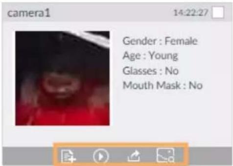
Table 6-2 Description
| Icon | Operation |
| Select one by one: Click the panel or move the mouse pointer onto the panel, and then click to select the panel. means it is selected.Batch select: Check All to select all panels on the page. | |
| Click or double-click the panel, the system starts to play back the recorded videos (about 10s). | |
| Click to quickly add the image to the face database. See "6.3.3.4.3 Adding Face Image" for detailed information. |







| Icon | Operation |
 | Export one by one: Clickto export picture, video and video player. For details, see "6.2.4.3 Exporting Face Records".Export in batches: Select the panel and clickto export picture, video or excel. For details, see "6.2.4.3 Exporting Face Records".[6+X;0]After setting alarm linkage snapshot, during exporting images, the system exports detected images and panoramic images at the time of snapshot. |
| Click, and then the system automatically searches all channels for the records of the current face. |
6.2.4.2 Searching by Image
Upload a face picture to search for similar faces.
You can select the to-be-uploaded face picture from local files or the face database.
- When you use face database images to search, ensure face database has been configured. See "6.3.3.4 Configuring Device Face Database" for detailed information.
- If you want to use the local images, you need to obtain the face image and save it in the corresponding path.
When operating on the local interface, save the image in the USB storage device and then connect the USB storage device to the Device.
When operating on the web or PC client, save the image on the PC in which the Web or PCAPP is located.

The function of search by image is not available with AI by Camera.
6.2.4.2.1 Searching Devices
Upload face image, compare it with face detection result of remote device, and find face detection information that meets the similarity.
Step 1 On the LIVE page, click +, and then select AI SEARCH > Search by Face > By Image.
Step 2 Click the Device tab.
Step 3 Upload a face image.

Device supports uploading maximum 50 face images. Device supports selecting maximum 10 face images at one time.
- Upload the image from the face image database to search for corresponding face.
1) Click ✦ Upload Image ▼ and select Staff Database Image.
Figure 6-12 Choose picture from face database
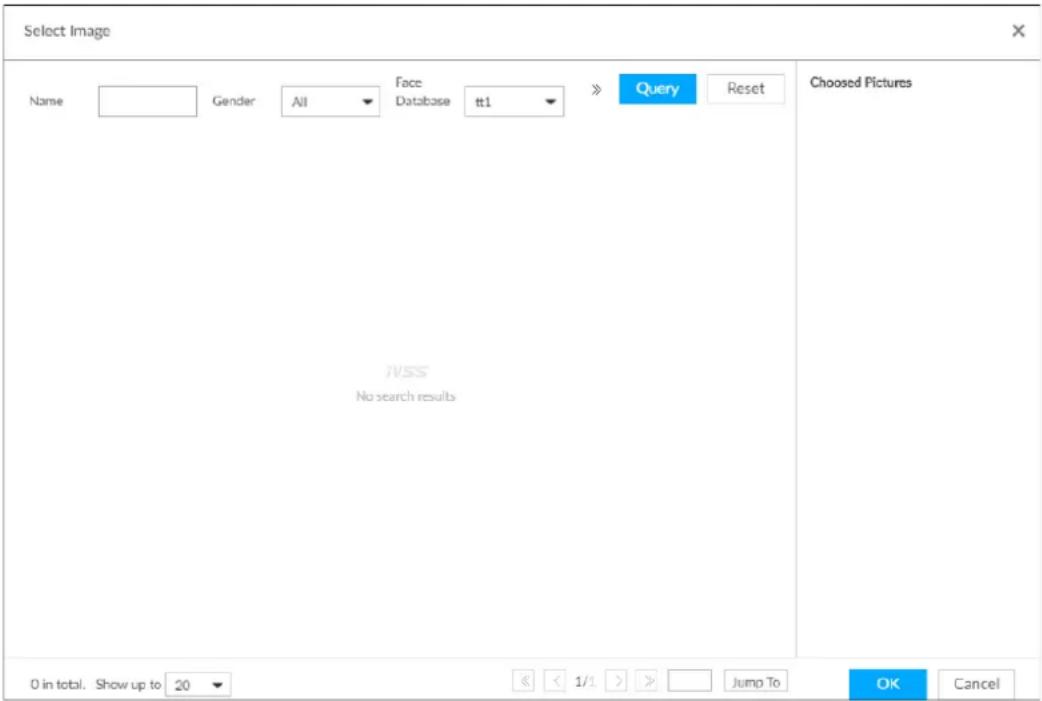
2) Specify search conditions.
3) Click Query.
4) Select a face image.
5) Drag to set similarity.
6) Click OK to upload face image.
- Upload the image from the passerby database.
1) Click ✦ Upload Image ▼ and select Passerby Database.
2) Specify search conditions.
3) Click Query.
4) Select a face image.
5) Click OK to upload face image.
- Local image: Upload images from the client PC or USB storage device connected to the Device.
1) Click + Upload Image and select Local.
2) Select the face image you want to upload.

You can select several face images at the same time.
3) Drag to set similarity.
4) Click OK to upload face image.
After uploading the images, device displays the face images on the upper-left corner. The latest 10 images are selected.
Figure 6-13 By image
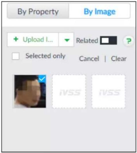

- When the uploaded image is half-length photo or full-body photo, the system automatically selects the frame of the uploaded image and only the face area will be retained.
- When there are multiple faces in the uploaded images, the system automatically identifies the faces in the images and uploads multiple face images according to the number of faces recognized.
- Device supports selecting maximum 10 face images.
- Click Cancel to cancel all selected face images.
- Select Selected only, device displays selected human face images only.
- Click Clear to clear all uploaded face images.
Step 4 (Optional) Click □ to enable related search. If related search is enabled, the system searches for both face detection results and human detection results.
Step 5 Hold on and drag to set human face similarity. It is 80% by default.
Step 6 Select remote device on the device list and then set record file time period.
Step 7 Click Query.
Figure 6-14 Search results
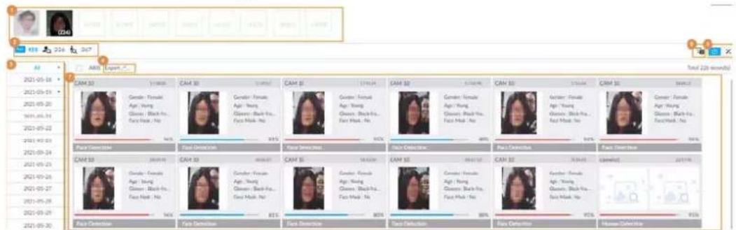
Table 6-3 Search results page description
| No. | Function |
| 1 | Displays the selected search images. The number at the lower-right corner of the image represents the number of records found.Click the image to view detailed results. |
| 2 | :displays the number of images found.:Displays the number of face images found.:Displays the number of human body images found.The numbers are displayed only when related search is enabled. |
| 3 | Displays the dates within the selected search range.Click a date and the records of that day are displayed. |
| 4 | Select the panel and clickto export picture, video or excel. For details, see "6.2.4.3 Exporting Face Records". |
| 5 Filter the search results according to properties. | |
| 6 | :Sortthe records by time:% : Sort the records by similarity. |
| 7 | Displays the face panels, including face image, feature property and similarity. |
6.2.4.2.2 Searching Face Database
Upload face image, compare it with face image in face database, and find face image that meets the similarity.
Step 1 On the LIVE page, click +, and then select AI SEARCH > Search by Face > By Image.
Step 2 Click the Face Database tab.
Step 3 Upload face image.
Step 4 (Optional) Click ☐ to enable related search. If related search is enabled, the system searches for both face detection results and human detection results.
Figure 6-15 Related
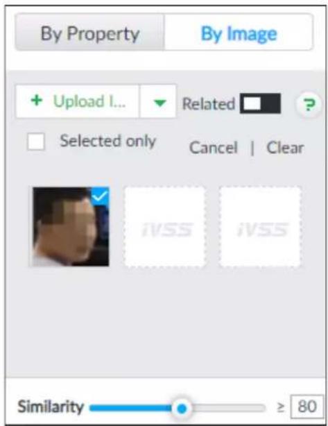
Step 5 Hold on and drag to set human face similarity. It is 80% by default.
Step 6 Select the face database.
Step 7 Click Query.
Figure 6-16 Search results
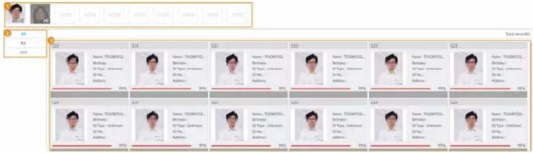
Table 6-4 Search results page description
| No. | Function |
| 1 | Displays the selected search images. The number at the lower-right corner of the image represents the number of records found.Click the image to view detailed results. |
| 2 | Displays the dates within the selected search range.Click a date and the records of that day are displayed. |
| 3 | Displays the face panels, including face image, feature property and similarity. |
6.2.4.2.3 Searching Task Lists
Upload face pictures to search for analyzed images of similar faces. For details about AI tasks, see "7.4.1 AI Analysis Task".
Step 1 On the LIVE page, click +, and then select AI SEARCH > Search by Face > By Image.
Step 2 Click the Task List tab.
Step 3 Upload a face picture.
Step 4 (Optional) Click ☐ to enable related search. If related search is enabled, the system searches for both face detection results and human detection results.
Figure 6-17 Related
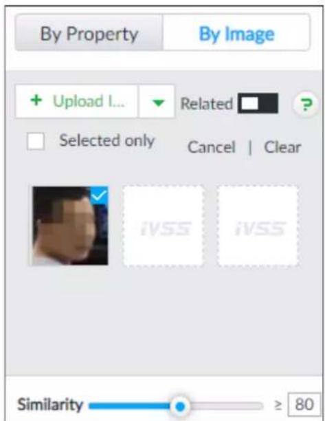
Step 5 Drag to set similarity. It is 80% by default.
Step 6 Select one or more tasks.
Step 7 Click Query.
Figure 6-18 Search results
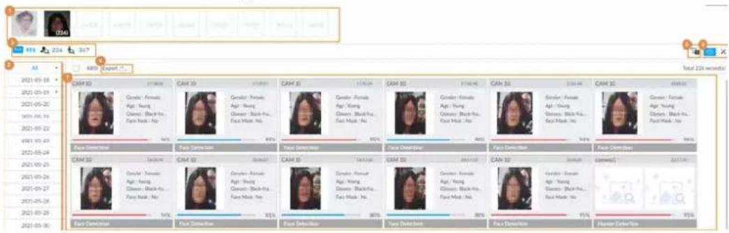
Table 6-5 Search results page description
| No. | Function |
| 1 | Displays the selected search images. The number at the lower-right corner of the image represents the number of records found.Click the image to view detailed results. |
| 2 | :displays the number of images found.: Displays the number of face images found.: Displays the number of human body images found.The numbers are displayed only when related search is enabled. |
| 3 | Displays the dates within the selected search range.Click a date and the records of that day are displayed. |
| 4 | Select the panel and clickto export picture, video or excel. For details, see "6.2.4.3 Exporting Face Records". |
| 5 Filter the search results according to properties. | |
| 6 | :Sort the records by time.: Sort the records by similarity. |
| 7 | Displays the face panels, including face image, feature property and similarity. |
6.2.4.3 Exporting Face Records
The search results of face records can be exported. You can select to export video, picture and excel that contain detailed information.

- Make sure that you have inserted USB storage device into your IVSS.
- The exported alarm-linked snapshot contains the face snapshot and the background picture.
- To save the background picture, make sure that you have configured alarm-linked snapshot storage.
The search results are displayed as follows.
Figure 6-19 Search results of face records
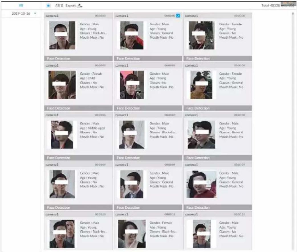
- Export in batches
Export more than one record. Support specifying file formats.
Step 1 Select more than one record.

To export all records, select the checkbox of All.
Step 2 Click ↗, and then select file formats.
Figure 6-20 File format
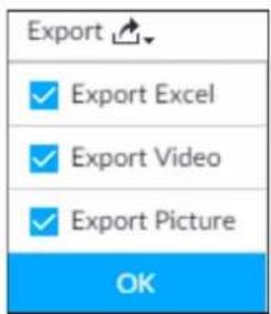
Step 3 Click OK, and then follow the onscreen instructions to finish exporting.
- Export one by one

- Point to a piece of record, and then click
- The Save page is displayed.
- Select a file type between DAV and MP4, set the saving path, and then click OK.
Export one piece of record. The exported file contains picture, video and video player by default.
6.3 Face Recognition
The system compares captured face with the face database and works out the similarity. When the similarity reaches the threshold as you have defined, an alarm will be triggered.
6.3.1 Configuration Modes
Face recognition can be configured in the following modes:
- Face recognition by camera. For details, see "6.3.2 Face Recognition by Camera".
- Face detection by camera+ face recognition by device. For details, see "6.3.3 Face Detection by Camera + Face Recognition by Device".
- Face recognition by camera + face recognition by device. For details, see "6.3.4 Face Recognition by Camera + Face Recognition by Device".
- Face detection by device + face recognition by device. For details, see "6.3.5 Face Detection by Device + Face Recognition by Device".
- Video metadata by camera or by device + face recognition by device. For details, see "6.3.6 Video Metadata + Face Recognition by Device".
6.3.2 Face Recognition by Camera
6.3.2.1 Configuration Procedure
Figure 6-21 Configure face recognition (AI by camera)

flowchart
graph LR
    A["Start"] --> B["Enable AI plan"]
    B --> C["Configure remote face database"]
    C --> D["Configure face recognition"]
    D --> E["Live view/face search"]
    E --> F["End"]
6.3.2.2 Enabling AI Plan
To use AI by camera, you need to enable the corresponding AI plan first. For details, see "6.2.1 Enabling AI Plan".
6.3.2.3 Configuring Remote Face Database
The Device can get face databases from the remote devices, and also allows creating face databases for remote devices. The remote device face database is suitable for face recognition AI by Camera.

You cannot view face image information on the remote devices from the Device.
6.3.2.3.1 Creating Face Database for Remote Devices
Procedure
Step 1 On the LIVE page, click +, and then select FILE >Face Management >Face Database >Remote.
Step 2 Select a remote device from the Remote Device drop-down list.
Step 3 Click Create.
Step 4 Enter Face database name.
Figure 6-22 Create a face database for remote devices
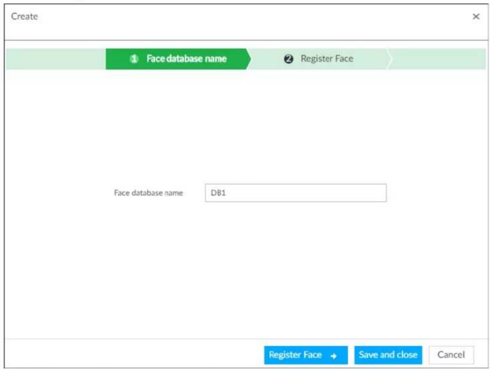
Step 5 Click Register Face or Save and close.
- To add faces into the database, click Register Face. For details, see #d1415e7a1026.
- To save and exit, click Save and close.
Related Operations
• View face database details and status.
Figure 6-23 Face database
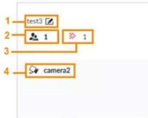
flowchart
graph TD
    A["1 test3"] --> B["2 1"]
    B --> C["3"]
    C --> D["4 camera2"]
◇ 1: Face database name. To modify, click .
◇ 2: Number of face images in the face database.
3: Number of face images that failed to abstract. For details about face abstracting, see "6.3.3.4.5 Human Face Abstract".
◇ 4: Face recognition devices associated to this face database.
- To arm the face database, see "6.3.2.4 Configuring Face Recognition (by Camera)".
• To delete face databases:
- To arm the face database, see "6.3.2.4 Configuring Face Recognition (by Camera)".
- To delete face databases:
One by one: Click .
In batches: Hover over the face database, and then select the database by clicking □. After selecting multiple databases, click .
◇ Delete all: Select All, and then click ☑.
- To clear a face database, select the face database, and then click Clear.
6.3.2.3.2 Adding Face Images for Remote Devices
Add face images to the created face database in the way of manual add, batch import, or bin import.

Make sure that you have obtained the face image and saved it in the proper path.
- When operating on the local interface, save the images in the USB storage device and then connect the USB storage device to the Device.
- When operating on the web or PCAPP interface, save the images on the PC you are using.
Manual Add
You can add human face image one by one. If the registered human face image quantity is small, you can use manual add mode.
-
On the LIVE page, click + and then select FILE > Face Management > Face Database > Remote.
-
Double-click a face database.
-
Click Manual Add.
-
Click and select face image.
Figure 6-24 Face register
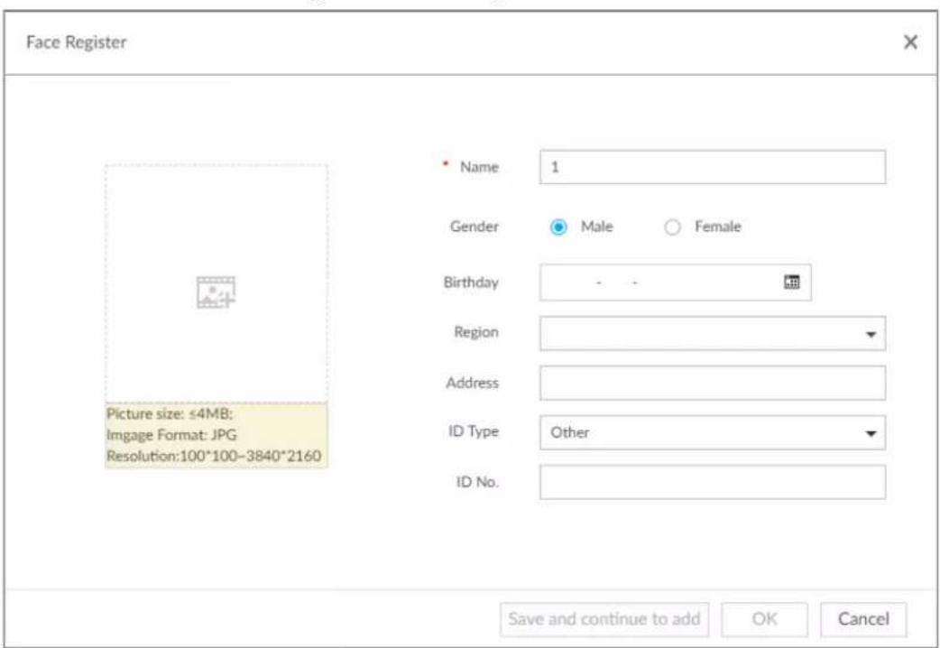

- When the uploaded image is half-length photo or full-body photo, the system automatically selects the frame of the uploaded image and only the face area will be retained.
- When there are multiple faces in the uploaded images, the system automatically identifies the
faces in the images and uploads multiple face images according to the number of faces recognized. Select face image you want to upload. Blue frame means that it is selected.
- Click Cancel to cancel all checked face images.
- Click OK and import face image.

Point to the face image and then click Change Image to change it.
- Fill in face image information.
Figure 6-25 Face information
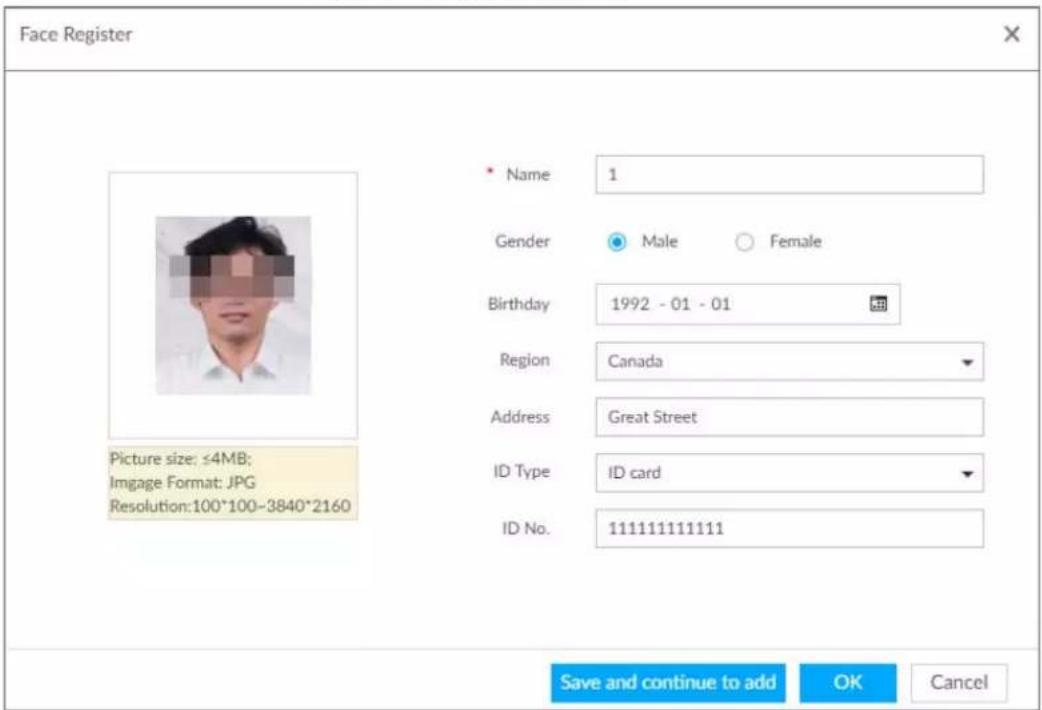
-
Click Save and continue to add or OK.
-
Click Save and Continue to add to save current face image information and add another human face image.
- Click OK to save current face image information and complete registration.
After adding the image, at the lower-left corner of the human face image, there is an icon 📁. It means device that face abstracting in process.
Batch Import
Before the batch import, name the face image according to the rule. After successful import, the system will identify the face image automatically.

Name is required and the rest are optional. For example, if you want to enter the name and ID number only, the naming can be Tim#S#B#N#P#T#M0000#A.jpg or Time#M0000.jpg.
Table 6-6 Naming rules for batch import
| Item | Description |
| Name Enter the corresponding name. | |
| Gender | Enter number. 1: Male; 2: Female. |
| Birthday | Enter number in the format of yyyymmdd or yyyy-mm-dd. For example, 20181123. |
| Region | Enter the corresponding abbreviation of the region. |
| Province | Enter the corresponding spelling or English name of the province. |
| ID type | Enter the corresponding number. 1. ID card, 2. Passport, 3. Others. |
| ID number | Fill in the corresponding ID number. |
| Address | Enter the detailed address. |
- On the LIVE page, click +, and then select FILE >Face Management >Face Database >Remote.
- Double-click a face database.
- Click Batch Import.
- Import face image.
- Upload a file: Click, select multiple face images, and then click Open.

You can select multiple face images by holding Shift and then clicking the first and the last face images, or holding Ctrl and then click the images one by one.
- Upload a folder: Click +, select the folder with face images, and then click Upload.
Figure 6-26 Batch import
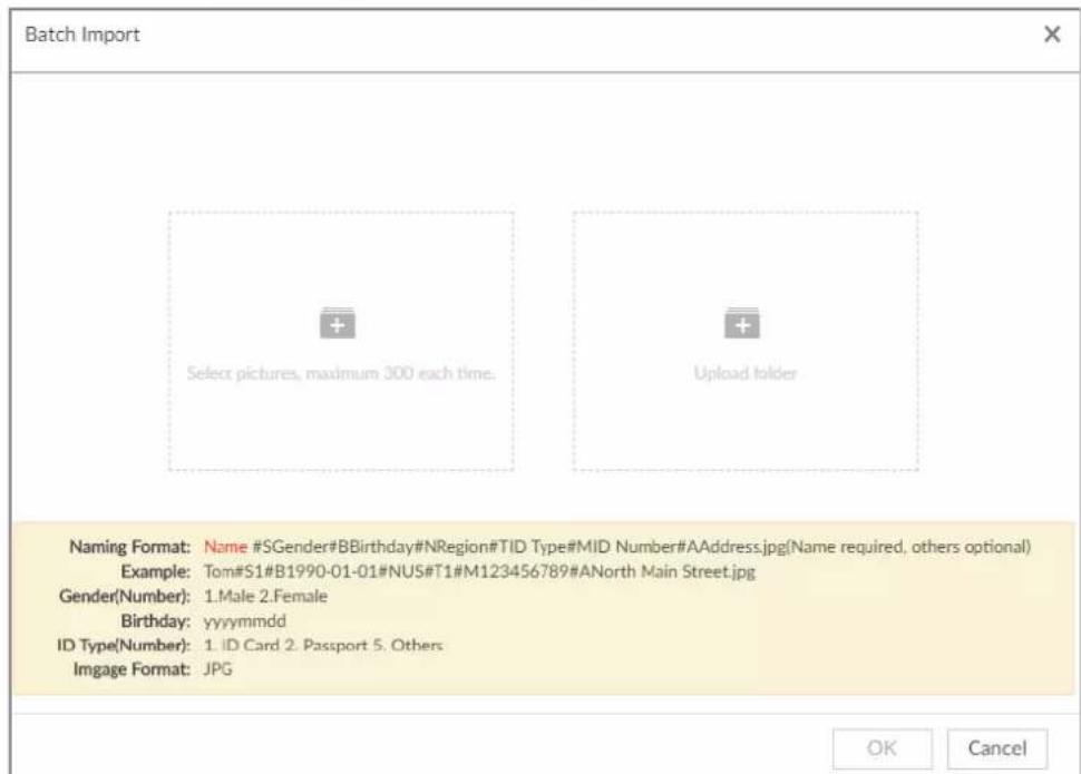
- Click OK.
-
Click Save and continue to add or OK.
-
Click Save and Continue to add to save current face image information and add another human face image.
- Click OK to save current face image information and complete registration.
After adding the image, at the lower-left corner of the human face image, there is an icon. It means device that face abstracting in process.
Bin Import
To import face images from another device into the current device, you can import a bin file of face images exported from that device.
- On the LIVE page, click +, and then select FILE >Face Management >Face Database >Remote.
- Double-click a face database.
- Click Bin Import.
- Enter the file Path and Password, and then click OK.

- The Password is the one created when the file was being exported.
- A bin file is divided into multiple parts when being exported if it is larger than 4 GB. When importing the file parts, you just need to select any one part of the file, and then all parts are imported.
Figure 6-27 Import bin files
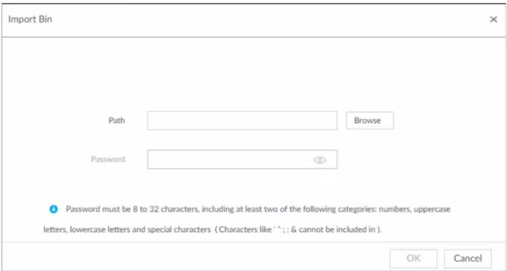
-
Click Save and continue to add or OK.
-
Click Save and Continue to add to save current face image information and add another human face image.
- Click OK to save current face image information and complete registration.
6.3.2.4 Configuring Face Recognition (by Camera)
Configure face recognition rules.
Step 1 Click 🎨 or click + on the configuration page, and then select EVENT.
Step 2 Select remote device in the device tree on the left.
Step 3 Select AI Plan >Face Recognition.
Figure 6-28 Face recognition (AI by Camera)
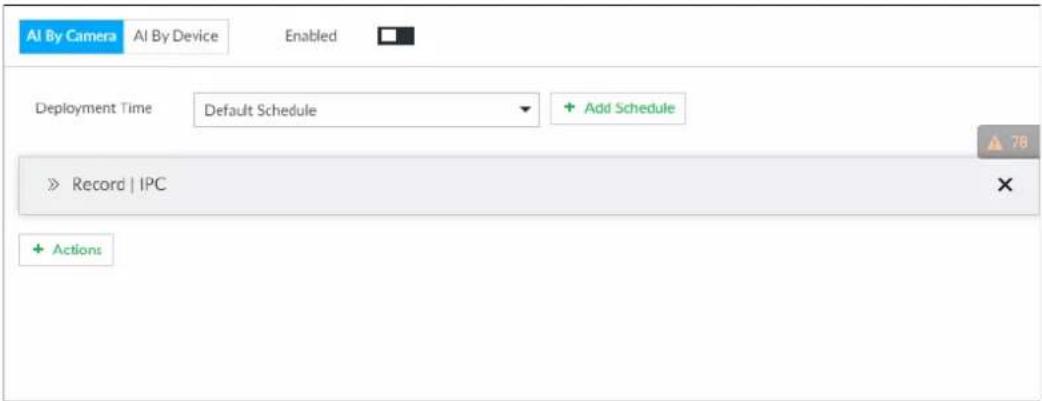
Step 4 Click AI by Camera, and then click ☐.
Step 5 Click Deployment Time to select schedule from the drop-down list.
After setting arm period, system triggers actions when there is a motion detection alarm in the specified period.
- Click View Schedule to view detailed schedule settings.
- If the schedule is not added or the added schedule does not meet actual needs, click Add Schedule. See "8.8.4 Schedule" for detailed information.
Step 6 Click Actions to set alarm actions. See "8.4.1 Alarm Actions" for detailed information.

Make sure that you have set face database on the camera.
Step 7 Click Save.
6.3.2.5 Live View of Face Recognition
Smart panel display. You can view real-time face detection and human face recognition images.
6.3.2.5.1 Setting AI Display
You can configure display rule of AI detection results.

Before using this function, ensure that view has been created. See "7.1.1 View Management" for detailed information.
Step 1 On the LIVE page, open a view window.
Step 2 Click ☐ and select the Face tab.

- Click Sync from AI-Dis., obtain global smart detection display rule of IVSS. See "8.4.2.4.2 Setting AI Display" for detailed information.
- Click Apply to all windows, it is to copy current configuration to other window(s).
Figure 6-29 Face
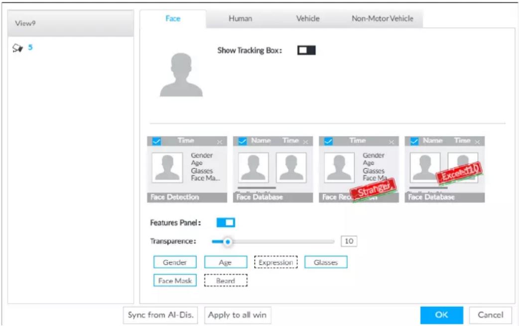
Step 3 Enable Show Tracking Box.
After it is enabled, when the system detects face or human, the window will display corresponding rule box.
Step 4 Enable features panel.
1) Click □ next to Features Panel, to enable the function. When the panel is enabled, the snapshots of detected faces are displayed on the live view.
2) Click ☐ to select Face Database, Stranger and Exceed10 tab. ✅ indicates that the panel is selected.
- If the Face Database panel is selected, it is displayed on the live video when the similarity between a detected face and one in the face database reaches the threshold.
- If the Stranger panel is selected, it is displayed on the live video when the similarity between a detected face and one in the face database does not reach the threshold.
- If the Exceed10 panel is selected, it is displayed on the live video when the similarity between a detected face and one in the face database reaches the threshold and the detected entries reach the defined number.
3) (Optional) Drag ☐ to adjust features panel transparency. The higher the value, the more transparent the features panel.
4) (Optional) Select the features you need to display.
- System supports displaying 4 feature types.
- System has checked four features by default. To select other features, cancel the selected features, and then select the ones you need.
Step 5 Click OK to save the configuration.
6.3.2.5.2 Live View
Go to the LIVE page, enable view, and then device displays view video.
- The view window displays currently detected face rule box.
- The right side displays features panel.
During face detection, features panel displays detection time, the detected face image and feature.
During face recognition, features panel displays detection time, the detected face image, face image in the database, comparison result and database name. After setting stranger mode, when the detected face image mismatches face image in the database, features panel will have Stranger tag.
Figure 6-30 Live
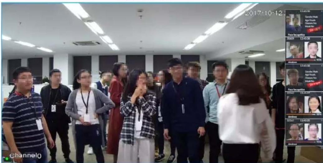
Point to a features panel, and then the operation icons are displayed.
- Click ☑ to add this image to the face database. See "6.8.3.2.3 Adding from Detection Results" for detailed information.
- Click 📋 or double-click the detected image, so the system starts to play back the recorded videos (about 10s) at the time of snapshot.
- Click to search for similar faces.
6.3.2.5.3 Face Total
On the LIVE page, click 📁. Face detection panel is displayed. Click 🔒, and then Face Recognition and Stranger. The face recognition results are displayed.
Figure 6-31 Detection image (1)
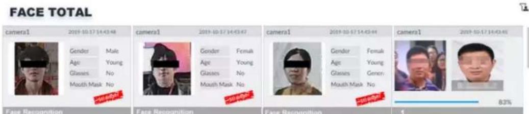
- Add the face image to the created face database.
Point to a piece of face record, and click 📄 to add this image to the face database. See "6.3.3.4.3 Adding Face Image" for detailed information. - Play the detection video.
Point to a piece of face record, and click 📋 or double-click the detected image, so the system starts to play back the recorded videos (about 10s) at the time of snapshot. - Export the record.
Point to a piece of face record, click , and then you can save the record, which contains video and picture.
- Search for similar target.
Point to a piece of face record, click , and then the system automatically searches for the similar faces in the defined period.

When operating on the local device (not from the web or PC client), make sure that you have connected the USB storage device.
6.3.2.6 Face Search
Search for face detection information, including face detection image, record and features. You can search by property or by image, export face records, and analyze similarity of two images.
6.3.2.6.1 Searching by Property
Step 1 On the LIVE page, click +, and then select AI SEARCH > Search by Face > By Property.
Figure 6-32 Search by property
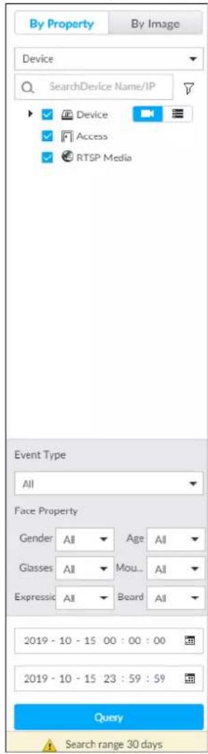
Step 2 Select a remote device, and then set Event Type to be Face Recognition.
Step 3 Select face mode and set face property and time.
Step 4 Click Query.
Figure 6-33 Search results
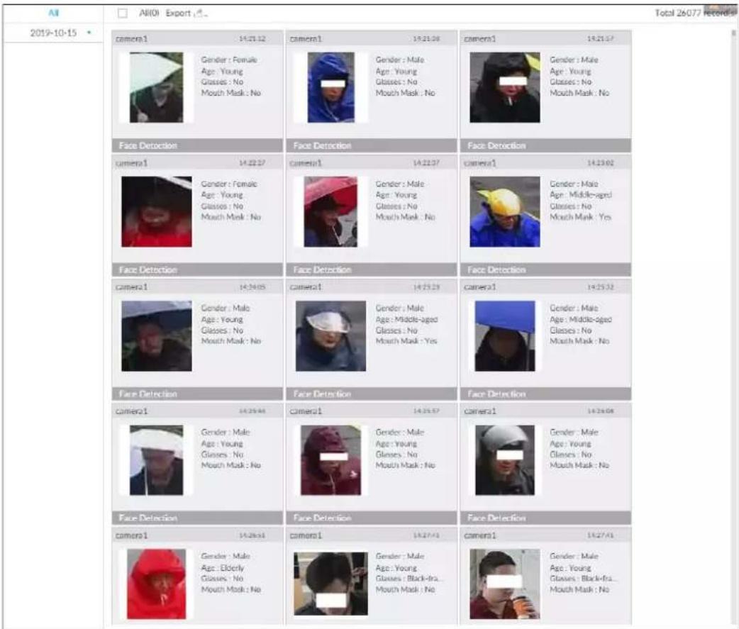
Point to a piece of record, and then the following icons are displayed.
Figure 6-34 Icons
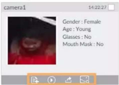
Table 6-7 Description
| Icon | Operation |
| Select one by one: Click the panel or move the mouse pointer onto the panel, and then click to select the panel. means it is selected.Batch select: Check All to select all panels on the page. | |
| Click or double-click the panel, the system starts to play back the recorded videos (about 10s). | |
| [167C] | Clickto quickly add the image to the face database. See "6.3.3.4.3 Adding Face Image" for detailed information. |
| [TX42] | Export one by one: Clickto export picture, video and video player. For details, see "6.2.4.3 Exporting Face Records".Export in batches: Select the panel and clickto export picture, video or excel. For details, see "6.2.4.3 Exporting Face Records".After setting alarm linkage snapshot, during exporting images, the system exports detected images and panoramic images at the time of snapshot. |
| [2376] | Click, and then the system automatically searches all channels for the records of the current face. |
6.3.2.6.2 Searching by Property
Search for images by property. For details, see "6.2.4.1 Searching by Property".
6.3.2.6.3 Searching by Image
Upload a face picture to search for the records of the same face. For details, see "6.2.4.2 Searching by Image".
6.3.2.6.4 Exporting Face Records
Export the searched face records, including pictures, videos and detailed information. For details, see "6.2.4.3 Exporting Face Records".
6.3.2.6.5 1:1 Face Recognition
Through 1:1 face recognition, the system analyzes the similarity between two images.
Step 1 On the LIVE page, click +, and then select AI SEARCH > 1:1 Face Recognition.
Figure 6-35 1:1 face recognition
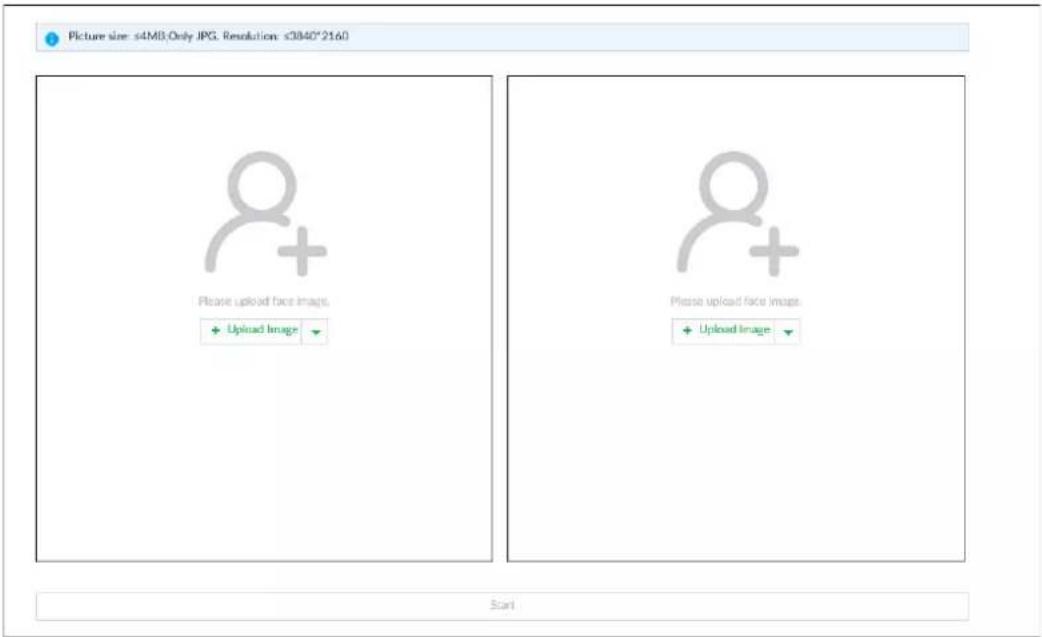
Step 2 Click + Upload Image and then upload two images to be compared.
Step 3 Click Start.
The comparison result will be displayed.
6.3.3 Face Detection by Camera + Face Recognition by Device
6.3.3.1 Configuration Procedure
Figure 6-36 Configure face detection (AI by camera)

flowchart
graph LR
    A["Start"] --> B["Enable AI plan"]
    B --> C["Configure face detection"]
    C --> D["Live view/face search"]
    D --> E["End"]
Figure 6-37 Configure face recognition (AI by device)

flowchart
graph LR
    A["Start"] --> B["Create face database"]
    B --> C["Add face image"]
    C --> D["Configure face recognition"]
    D --> E["Live view/face search"]
    E --> F["End"]
6.3.3.2 Enabling AI Plan
To use AI by camera, you need to enable the corresponding AI plan first. For details, see "6.2.1 Enabling AI Plan".
6.3.3.3 Configuring Face Detection (by Camera)
Configure alarm rule of face detection.
Step 1 Click 🎨 or click + on the configuration page, and then select EVENT.
Step 2 Select a remote device in the device tree on the left.
Step 3 Select AI Plan > Face Detection.
Figure 6-38 AI by camera
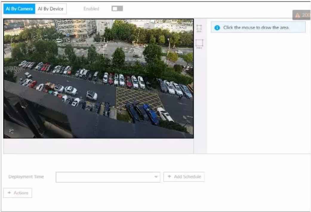
Step 4 Click AI by camera, and then click □ to enable face detection.

AI by camera supports Face Enhancement. After enabling Face Enhancement, system displays enhanced human face zone on the surveillance window.
Step 5 Set detection area on the video (yellow area).
Figure 6-39 Area
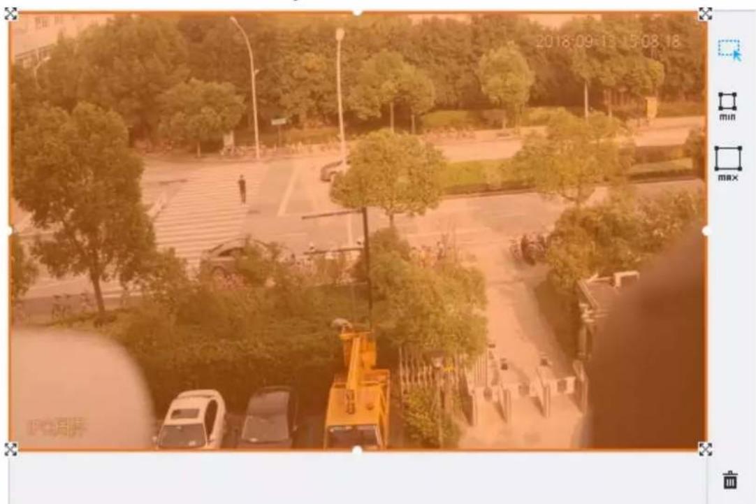
- Click ✗ or white dot on detect region frame, and drag to adjust its range.
- Click ☐ or ☐ to set the minimum size or maximum size of the face detection area.
System triggers an alarm once the size of detected target is between the maximum size and the minimum size.
Step 6 Click Deployment Time to select a schedule from the drop-down list.
System triggers corresponding alarm actions only during the alarm deployment period.

You can select an existing schedule from the Deployment Time drop-down list. You can also add a new schedule. For details, see "8.8.4 Schedule".
Step 7 Click Actions to set alarm action. See "8.4.1 Alarm Actions" for detailed information.
Step 8 Click Save.
6.3.3.4 Configuring Device Face Database
You can create face databases on the device to manage face images for face recognition (by device).
6.3.3.4.1 Creating Human Face Database
Create human face database to sort out and manage the face images uploaded to the device.
Procedure
Step 1 On the LIVE page, click + and then select FILE > Face Management > Face Database > Local.
Step 2 Click Create.
Figure 6-40 Create face database
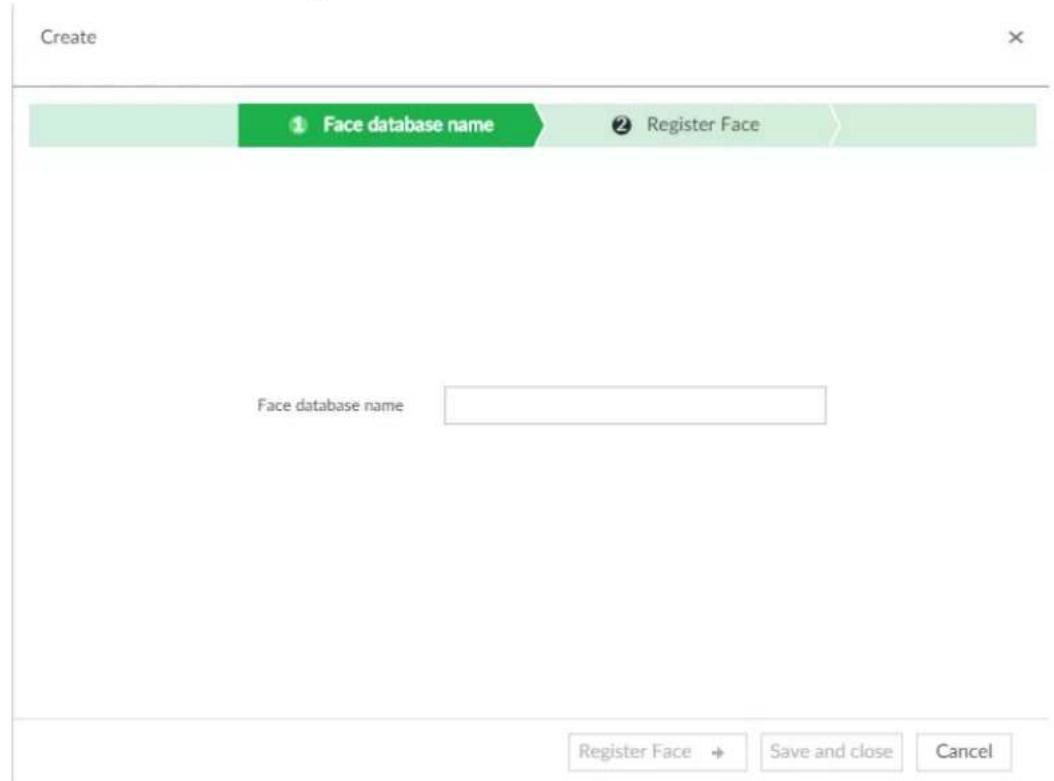
Step 3 Set face database name.

- Number: The proportion of the number of added face images in the face databases and passerby databases to the allowed face images in total.
- Space: The proportion of the space occupied by the face databases and passerby databases to the allowed space in total.
Step 4 Click Register Face or Save and close.
- Click Register face, and then add human face on the newly created human database.
- Click Save and close to create a human face database with no data.
Related Operations
• View face database details and status.
Figure 6-41 Face database
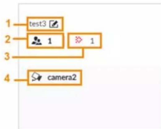
flowchart
graph TD
    A["1 test3"] --> B["2 1"]
    B --> C["3"]
    C --> D["4 camera2"]
◇ 1: Face database name. To modify, click .
◇ 2: Number of face images in the face database.
3: Number of face images that failed to abstract. For details about face abstracting, see "6.3.3.4.5 Human Face Abstract".
◇ 4: Face recognition devices associated to this face database.
- To manage face images, double-click the face database.
- To arm the face database, see "6.3.3.5 Configuring Face Recognition (by Device)".
• To delete face databases:
One by one: Click .
In batches: Hover over the face database, and then select the database by clicking ☐. After selecting multiple databases, click .
◇ Delete all: Select All, and then click 🔒.
- To clear a face database, select the face database, and then click Clear.
6.3.3.4.2 Exporting Face Database
You can export a bin file of face images from the current device into another device so that the face database can be shared among devices. The exported file is encrypted for better security.
Step 1 On LIVE page, click +, and then select FILE >Face Management >Face Database >Local.
Step 2 Select one or more face databases from which you want to export face images, and then click Bin Export.
Step 3 Enter the file Path and Password, and then click OK.
- The Path is the one where the exported bin file is saved.
- The Password is the one used when the file is being imported.

If the bin file being exported is larger than 4 GB, the file is divided into multiple parts, with the first named as device name_database name_exporting time_part1.zip.
6.3.3.4.3 Adding Face Image
Add face images to the created face database in the way of manual add, batch import, bin import or detection.

Make sure that you have obtained the face image and saved it in the proper path.
- When operating on the local interface, save the image in the USB storage device and then connect the USB storage device to the Device.
- When operating on the web or PCAPP interface, save the image on the PC in which the web or PCAPP is located.
Manual Add
You can add human face image one by one. If the registered human face image quantity is small, you can use manual add mode.
- On LIVE page, click + and then select FILE >Face Management >Face Database >Local.
- Double-click a face database.
- Click Manual Add.
Figure 6-42 Manual add

- Click and select face image.
Figure 6-43 Face register
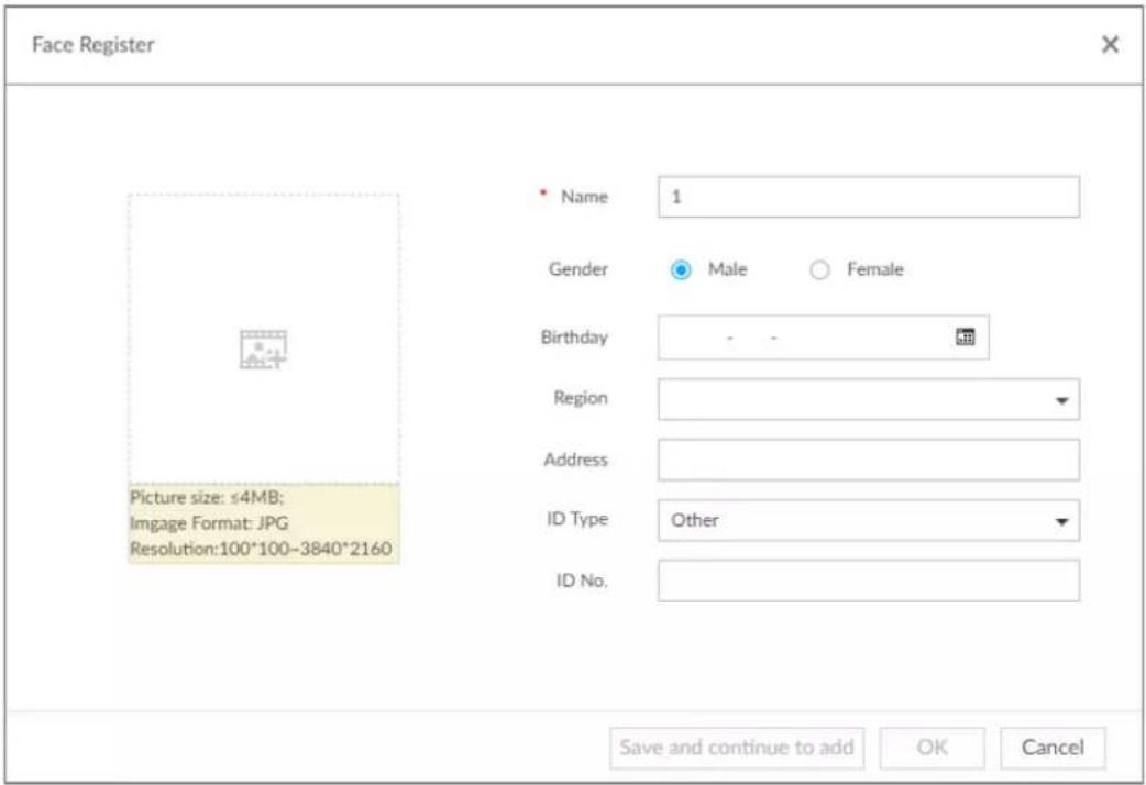

- When the uploaded image is half-length photo or full-body photo, the system automatically selects the frame of the uploaded image and only the face area will be retained.
- When there are multiple faces in the uploaded images, the system automatically identifies the faces in the images and uploads multiple face images according to the number of faces recognized. Select face image you want to upload. Blue frame means that it is selected.
-
Click Cancel to cancel all checked face images.
-
Click OK and import face image.

Point to the face image and then click Change Image to change it.
- Fill in face image information.
Figure 6-44 Face information
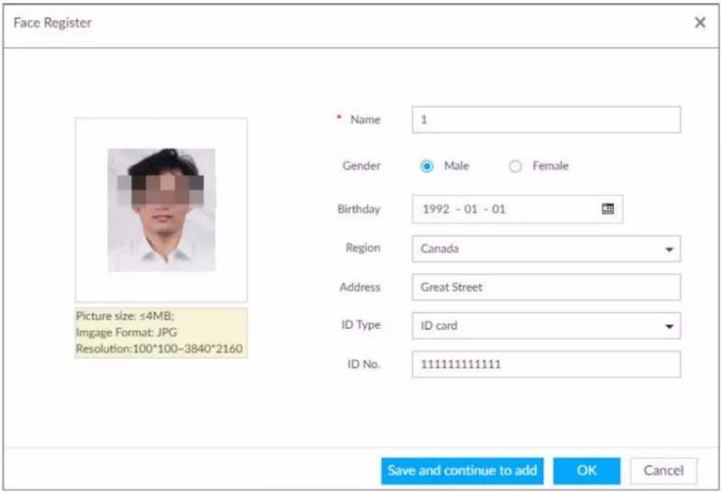
-
Click Save and continue to add or OK.
-
Click Save and Continue to add to save current face image information and add another human face image.
- Click OK to save current face image information and complete registration.
After adding the image, at the lower-left corner of the human face image, there is an icon 📁. It means device that face abstracting in process.
Batch Import
Before the batch import, name the face image according to the rule. After successful import, the system will identify the face image automatically.

Name is required and the rest are optional. For example, if you want to enter the name and ID number only, the naming can be Tim#S#B#N#P#T#M0000#A.jpg or Time#M0000.jpg.
Table 6-8 Naming rules for batch import
| Item | Description |
| Name Enter the corresponding name. | |
| Gender | Enter number. 1: Male; 2: Female. |
| Birthday | Enter number in the format of yyyyMMdd or yyyy-mm-dd. For example, 20181123. |
| Region | Enter the corresponding abbreviation of the region. |
| Province | Enter the corresponding spelling or English name of the province. |
| ID type | Enter the corresponding number. 1. ID card, 2. Passport, 3. Others. |
| ID number | Fill in the corresponding ID number. |
| Address | Enter the detailed address. |
- On LIVE page, click +, and then select FILE >Face Management >Face Database >Local.
- Double-click a face database.
- Click Batch Import.
- Import face image.
- Upload a file: Click, select multiple face images, and then click Open.

You can select multiple face images by holding Shift and then clicking the first and the last face images, or holding Ctrl and then click the images one by one.
- Upload a folder: Click +, select the folder with face images, and then click Upload.
Figure 6-45 Batch import
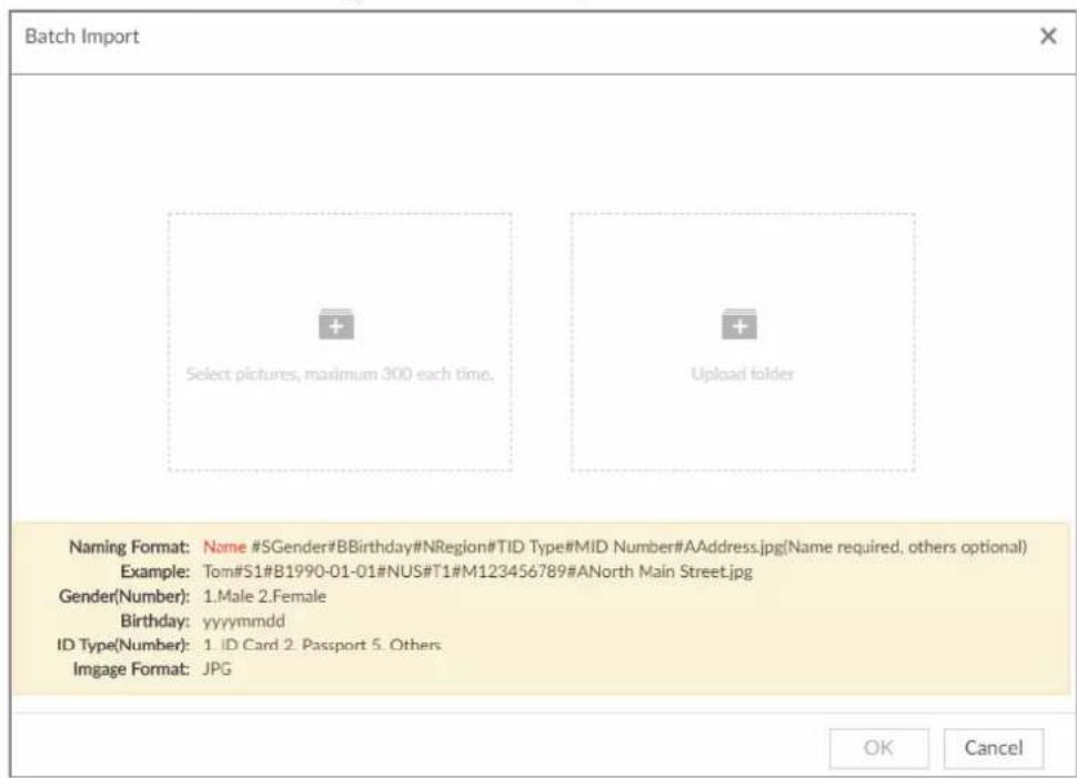
- Click OK.
-
Click Save and continue to add or OK.
-
Click Save and Continue to add to save current face image information and add another human face image.
- Click OK to save current face image information and complete registration.
After adding the image, at the lower-left corner of the human face image, there is an icon 📁. It means device that face abstracting in process.
Bin Import
To import face images from another device into the current device, you can import a bin file of face images exported from that device.
- On LIVE page, click +, and then select FILE >Face Management >Face Database >Local.
- Double-click a face database.
- Click Bin Import.
- Enter the file Path and Password, and then click OK.

- The Password is the one created when the file was being exported.
- A bin file is divided into multiple parts when being exported if it is larger than 4 GB. When importing the file parts, you just need to select any one part of the file, and then all parts are imported.
Figure 6-46 Import bin files
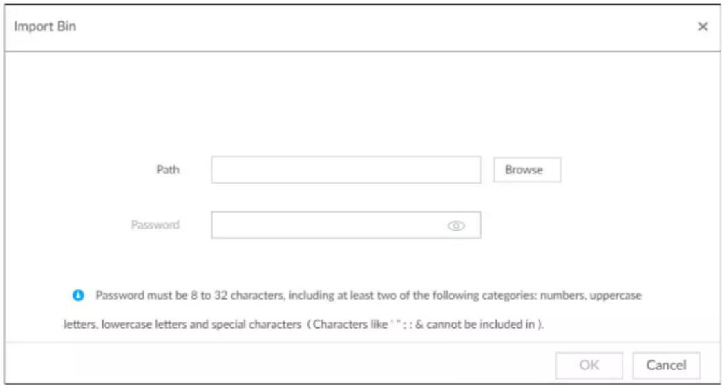
-
Click Save and continue to add or OK.
-
Click Save and Continue to add to save current face image information and add another human face image.
- Click OK to save current face image information and complete registration.
Adding from Detection Snapshots
Add the snapshot of AI detection to the created face database.
- Select face images on the LIVE page.
The following two ways are available.
- Point to a face snapshot in the refreshing snapshot list on the right of the live video, and then click 📄
- Click, point to a face snapshot, and then click.
Figure 6-47 Face register
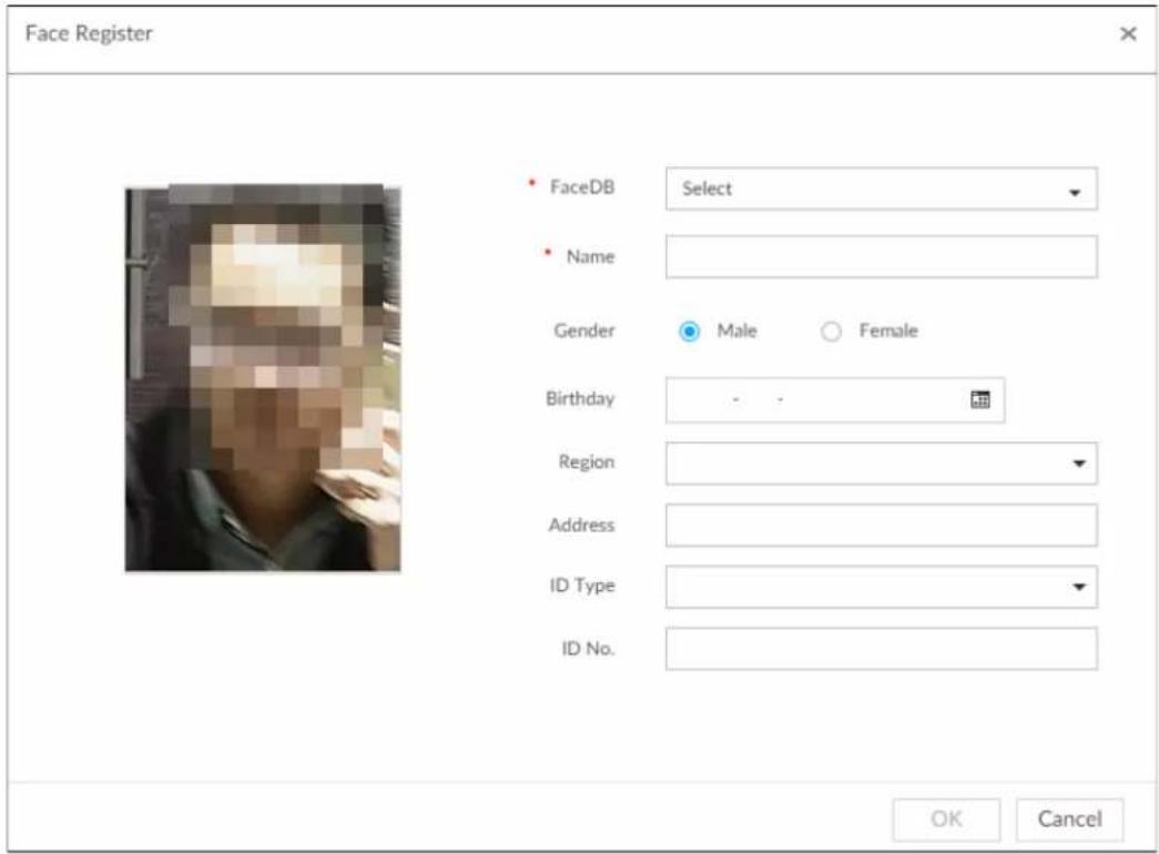
- Select a face database, and fill in person information according to your actual situation.
- Click OK to save the configuration.
6.3.3.4.4 Creating Passerby Database
If you configure an alarm to link passerby database, when the detected face is not in the face database, system automatically captures the face image, and then save it to the passerby database.
Procedure
Step 1 On the LIVE page, click +, and then select FILE > Face Management > Face Database > PasserBy Database.
Step 2 Click Create Passerby Database.
Figure 6-48 Passerby database
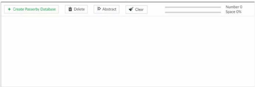

- Number: The proportion of the number of added face images in the face databases and passerby databases to the allowed face images in total.
- Space: The proportion of the space occupied by the face databases and passerby
databases to the allowed space in total.
Step 3 Enter the passerby database information, and then click OK.
Figure 6-49 Create a passerby database
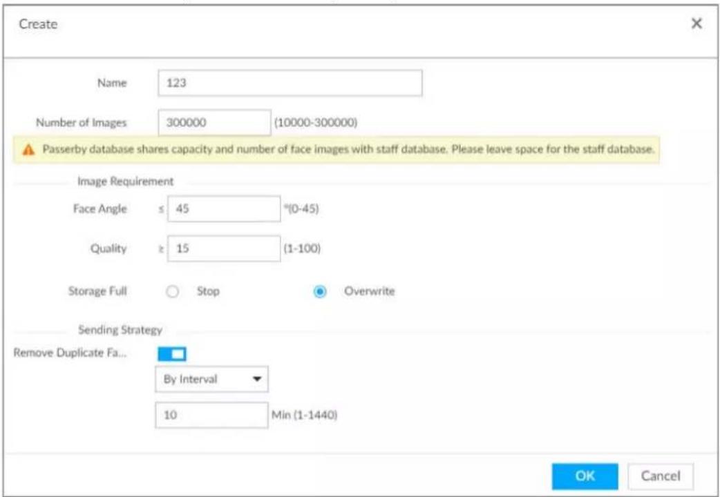
Table 6-9 Parameters of creating passerby database
| Parameter | Description |
| Name | Enter the name of the database. |
| Number of Images | Configure how many face images the database can store.Maximum = Total number of face images of the Device - the face image number of the current staff databases - the face image number of the current passerby databases.Minimum: 10,000. |
| Face Angle | Set the allowed pitch angle and yaw angle of the face image. The value ranges from 0 through 45 degrees. The smaller the angle, the more accurate the face image. |
| Quality | Only face images within the allowed quality range (1 to 100) can be added. |
| Storage Full | The storage strategy when storage space is used up.Stop: No more images can be added.Overwrite: The newest images overwrite the oldest images. Back up the old images as necessary. |
| Remove Duplicate Faces | When the captured face image is found in the passerby database, and the quality is higher than that of the one in the database, the system replaces the face image in the database. A successful comparison of the captured image against the database will not be reported.Always: Always remove duplicate face images.By Interval: Remove duplicate face images by interval to control comparison pressure.By Duration: Within the defined time period, if a captured face image is found in the passerby database, the system replaces the image in the database with the new one. |
Related Operations
- View face database details and status.
Figure 6-50 Face database
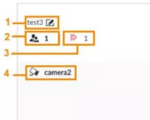
flowchart
graph TD
    A["1 test3"] --> B["2 1"]
    B --> C["3 1"]
    C --> D["4 camera2"]
◇ 1: Face database name. To modify, click .
◇ 2: Number of face images in the face database.
3: Number of face images that failed to abstract. For details about face abstracting, see "6.3.3.4.5 Human Face Abstract".
◇ 4: Face recognition devices associated to this face database.
- To manage face images, double-click the face database.
- To arm the face database, see "6.3.3.5 Configuring Face Recognition (by Device)".
- To delete face databases:
One by one: Click .
In batches: Hover over the face database, and then select the database by clicking □. After selecting multiple databases, click .
◇ Delete all: Select All, and then click ☑.
- To clear a face database, select the face database, and then click Clear.
6.3.3.4.5 Human Face Abstract
The human face abstracting is to abstract the corresponding information of the face image and import to the database. After that, device can compare human face, and search for human face.

- The greater the face image quantity is, the longer the face abstracting time it takes.
- During the abstracting process, some intelligent functions (such as human face recognition, search human face and so on.) are null. These functions become normal after the abstracting process is completed.
Step 1 On the LIVE page, click +, and then select FILE >Face Management >Face Database.
Step 2 Double-click a face database.
Step 3 Select face images and then click Abstract.

- Select All to select all face images on current human face database.
- If there are too many human face images on the human face database, click 🔒 to set search criteria (such as name, gender, birthday, country, province, ID type, ID number or abstracting status) to quickly find the human face images.
Step 4 Click Start Abstract.
Device begins processing face information.
The abstracting is successful if is no longer at the lower-left corner of the face image.
The abstracting might fail if the face image is not clear or does not contain complete information, and 📋 appears at the lower-left corner of the face image.
Figure 6-51 Abstract result
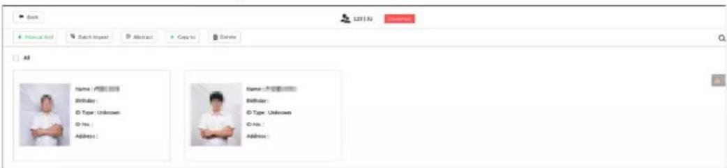
6.3.3.4.6 Managing Face Pictures
Maintain and manage face images in the face database to ensure that people information is always correct. The system supports editing face picture information, copying face pictures to other face database and deleting face pictures.
On the LIVE page, click +, and then select FILE > Face Management > Face Database. Double-click a face database, the face pictures in the database are displayed.
Editing Face Pictures
- In the face database, point to a face picture, and then click ☑.
- After editing, click OK.
Copying Face Pictures
- In the face database, point to a face picture, and then click □ to select the face picture.

-
You can select more than one pictures.
• To select all pictures, click All. -
Click Copy to.
Figure 6-52 Copy to
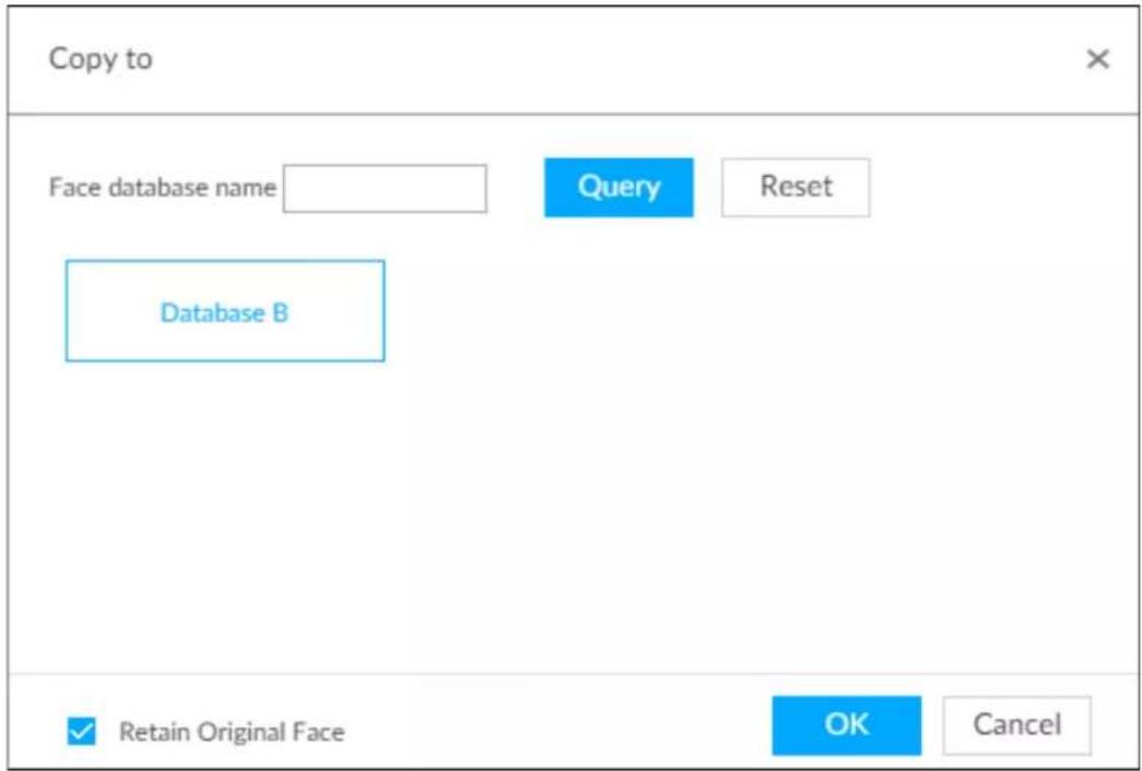
- Select a face database.

- You can select more than one face databases.
- You can also select a face database by entering the database name in the Face database name box and clicking Query.
-
Select the checkbox of Retain Original Face to keep the original face pictures in the database. It is selected by default.
-
Click OK.
Deleting Face Pictures
Two ways are available to delete face pictures in the face database.
- One by one: Point to the face picture, and then click .
- In batches:
Point to the face picture, and then click . By the same way, select more pictures, and then click Delete. The selected face pictures are deleted.
◇ Click All, and then click Delete. All the face pictures in this page are deleted.
6.3.3.5 Configuring Face Recognition (by Device)
Configure face recognition rules.
To use AI by device, enable face detection first. For details, see "6.2.2 Configuring Face Detection".
Step 1 Click 🎨 or click + on the configuration page, and then select EVENT.
Step 2 Select remote device in the device tree on the left.
Step 3 Select AI Plan >Face Recognition.
Figure 6-53 Face recognition (AI by Device)
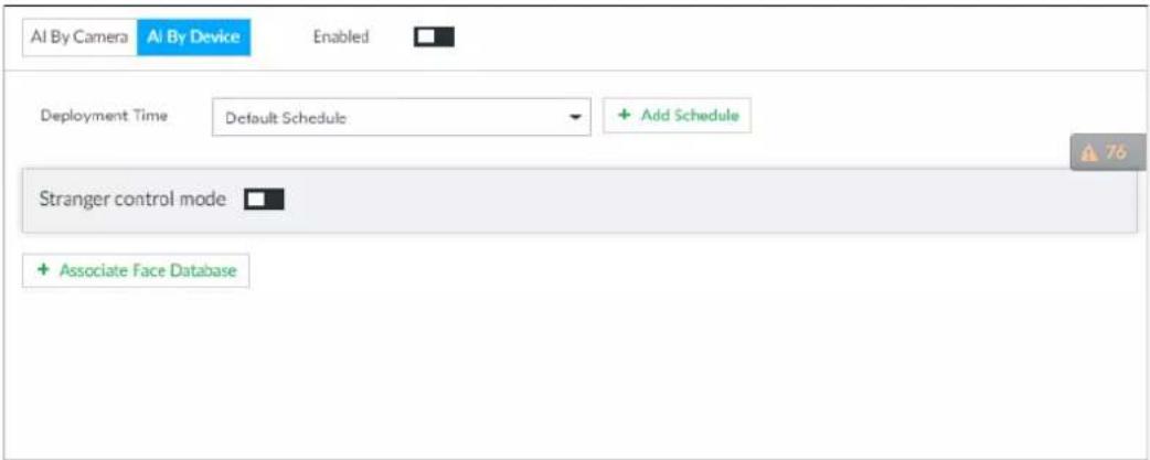
Step 4 Click AI by Device, and then click ☐.
Step 5 Click Deployment Time to select schedule from the drop-down list.
After setting arm period, system triggers actions when there is a motion detection alarm in the specified period.
- Click View Schedule to view detailed schedule settings.
- If the schedule is not added or the added schedule does not meet actual needs, click Add Schedule. See "8.8.4 Schedule" for detailed information.
Step 6 Set stranger mode.
Enable stranger mode. Once the face recognition similarity is lower than the specified value, system triggers an alarm.
1) Click □ to enable stranger mode.
Figure 6-54 Stranger control mode
![Stranger control mode Air Alarm Rule Show feature Panel Log 1 Enable Local Alarm Out[ Output Part]](/content/2026/05/1061580/images/c4c9ec970ac2232f297d0330b2385ea10245d8e20399e4ae7c41098c6cba836a.jpg)
2) Set parameters.
Table 6-10 Stranger control mode description
| Parameters | Description |
| AI alarm rule | Click [65xx] to set alarm rule box color. |
| Show feature panel | Click □ enable features panel function. System displays stranger panel once there is an alarm. |
3) Click Actions to set alarm actions. See "8.4.1 Alarm Actions" for detailed information.
Step 7 Set linked face database.

Repeat the step to trigger several human databases at the same time.
1) Click Associate Face database, and then select the triggered human face database.
Figure 6-55 Face database configuration

2) Click □ to enable association with the database and then set parameters.
Table 6-11 Configuration description
| Parameters | Description |
| Delete the associated database. | |
| Similarity | It is to set human face similarity.System compares the human face with the image on the face database. System triggers an alarm once the similarity reaches the threshold you set here. |
| AI alarm rule | Click ▲ to set alarm rule box color. |
| Show feature panel | Click □ enable features panel function. System displays features panel once there is an alarm. |
3) Click Actions to set alarm actions. See "8.4.1 Alarm Actions" for detailed information.
Step 8 Set linked passerby database.

- You can link passerby database only when AI by device is used.
- One device can be linked with only one passerby database.
1) Click Associate Face database, and then select a passerby database.
2) Set parameters.
3) Click Actions to set alarm actions. See "8.4.1 Alarm Actions" for detailed information.
Step 9 Click Save.
6.3.3.6 Live View
Smart panel display. You can view real-time face detection and human face recognition images. For details, see "6.3.2.5 Live View of Face Recognition".
6.3.3.7 Face Search
Search for face detection information, including face detection image, record and features. You can search by property or by image, export face records, and analyze similarity of two images. For details, see "6.3.2.6 Face Search".
6.3.4 Face Recognition by Camera + Face Recognition by Device
6.3.4.1 Configuration procedure
Figure 6-56 Configure face recognition (AI by camera)

flowchart
graph LR
    A["Start"] --> B["Enable AI plan"]
    B --> C["Configure face recognition"]
    C --> D["Live view/face search"]
    D --> E["End"]
Figure 6-57 Configure face recognition (AI by device)

flowchart
graph LR
    A["Start"] --> B["Create face database"]
    B --> C["Add face image"]
    C --> D["Configure face recognition"]
    D --> E["Live view/face search"]
    E --> F["End"]
6.3.4.2 Enabling AI Plan
To use AI by camera, you need to enable the corresponding AI plan first. For details, see "6.2.1 Enabling AI Plan".
6.3.4.3 Configuring Face Recognition (by Camera)
Configure face recognition rules. For details, see "6.3.2.4 Configuring Face Recognition (by Camera)".
6.3.4.4 Configuring Device Face Database
You can create face databases on the device to manage face images for face recognition (by device). For details, see "6.3.3.4 Configuring Device Face Database".
6.3.4.5 Configuring Face Recognition (by Device)
Configure face recognition rules. For details, see "6.3.3.5 Configuring Face Recognition (by Device)".
6.3.4.6 Live View
Smart panel display. You can view real-time face detection and human face recognition images. For details, see "6.3.2.5 Live View of Face Recognition".
6.3.4.7 Face Search
Search for face detection information, including face detection image, record and features. You can search by property or by image, export face records, and analyze similarity of two images. For details, see "6.3.2.6 Face Search".
6.3.5 Face Detection by Device + Face Recognition by Device
6.3.5.1 Configuration Procedure
Figure 6-58 Configure face detection (AI by device)

flowchart
graph LR
    A["Start"] --> B["Configure face detection"]
    B --> C["Live view/face search"]
    C --> D["End"]
Figure 6-59 Configure face recognition (AI by device)

flowchart
graph LR
    A["Start"] --> B["Create face database"]
    B --> C["Add face image"]
    C --> D["Configure face recognition"]
    D --> E["Live view/face search"]
    E --> F["End"]
6.3.5.2 Configuring Face Detection (by Device)
Configure alarm rule of face detection.
Step 1 Click 🎨 or click + on the configuration page, and then select EVENT.
Step 2 Select a remote device in the device tree on the left.
Step 3 Select AI Plan > Face Detection.
Figure 6-60 AI by device
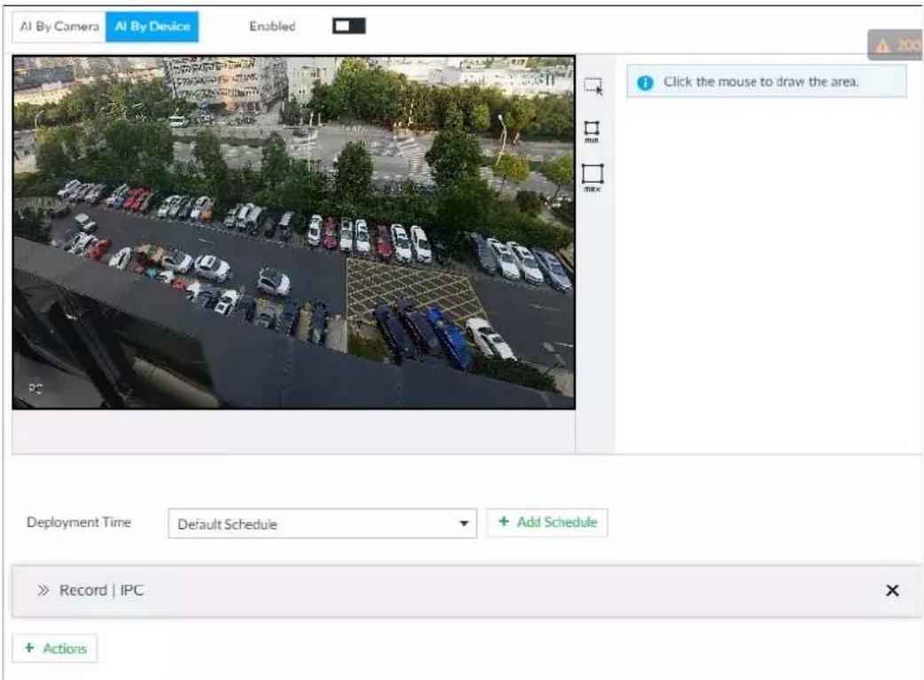
Step 4 Click AI by device, and then click □ to enable face detection.
Step 5 Set detection area on the video (yellow area).
Figure 6-61 Area
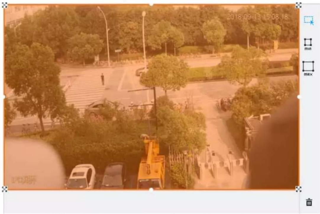
- Click ✗ or white dot on detect region frame, and drag to adjust its range.
- Click ☐ or ☐ to set the minimum size or maximum size of the face detection area. System triggers an alarm once the size of detected target is between the maximum size and the minimum size.
Step 6 Click Deployment Time to select a schedule from the drop-down list.
System triggers corresponding alarm actions only during the alarm deployment period.

You can select an existing schedule from the Deployment Time drop-down list. You can also add a new schedule. For details, see "8.8.4 Schedule".
Step 7 Click Action to set alarm action. See "8.4.1 Alarm Actions" for detailed information.
Step 8 Click Save.
6.3.5.3 Configuring Device Face Database
You can create face databases on the device to manage face images for face recognition (by device). For details, see "6.3.3.4 Configuring Device Face Database".
6.3.5.4 Configuring Face Recognition (by Device)
Configure face recognition rules. For details, see "6.3.3.5 Configuring Face Recognition (by Device)".
6.3.5.5 Live View
Smart panel display. You can view real-time face detection and human face recognition images. For details, see "6.3.2.5 Live View of Face Recognition".
6.3.5.6 Face Search
Search for face detection information, including face detection image, record and features. You can search by property or by image, export face records, and analyze similarity of two images. For details, see "6.3.2.6 Face Search".
6.3.6 Video Metadata + Face Recognition by Device

For scenes that prioritize the accuracy of face recognition, we recommend the combination of face detection and face recognition. Video metadata is not an ideal option for face recognition in such scenes.
6.3.6.1 Configuration Procedure
Figure 6-62 Configure video metadata (AI by camera)

flowchart
graph LR
    A["Start"] --> B["Enable AI plan"]
    B --> C["Configure video metadata"]
    C --> D["Live view/Al search"]
    D --> E["End"]
Figure 6-63 Configure video metadata (AI by device)

flowchart
graph LR
    A["Start"] --> B["Configure video metadata"]
    B --> C["Live view/AI search"]
    C --> D["End"]
Figure 6-64 Configure face recognition (AI by device)

flowchart
graph LR
    A["Start"] --> B["Create face database"]
    B --> C["Add face image"]
    C --> D["Configure face recognition"]
    D --> E["Live view/face search"]
    E --> F["End"]
6.3.6.2 Enabling AI Plan
Enable AI plan when AI by camera is used. See "6.2.1 Enabling AI Plan" to enable video metadata function.
6.3.6.3 Configuring Video Metadata
The Device supports metadata by camera (AI by Camera on the page) or by the Device (AI by Device on the page). For details about the configuration operation, see "6.5.2 Configuring Video Metadata"
6.3.6.4 Configuring Face Recognition (by Device)
Configure face recognition rules. For details, see "6.3.3.5 Configuring Face Recognition (by Device)".
6.3.6.5 Live View
Smart panel display. You can view real-time face detection and human face recognition images. For details, see "6.3.2.5 Live View of Face Recognition".
6.3.6.6 Face Search
Search for face detection information, including face detection image, record and features. You can search by property or by image, export face records, and analyze similarity of two images. For details, see "6.3.2.6 Face Search".
6.4 People Counting
This section introduces the statistics of in-area people number, and queuing number.

- The people counting function is only available with AI by camera. Make sure that the camera has been configured with people counting rules.
- The old people counting data will be overwritten when the storage space runs out. You are recommended to back up the data in time.
6.4.1 Enabling AI Plan
To use AI by camera, you need first enable the corresponding AI plan; otherwise the AI function does not work. For details, see "6.2.1 Enabling AI Plan".
6.4.2 Configuring People Counting
The system counts the number of people in and out of the detection area. When the number of entry, exit or stay is larger or smaller than the threshold, an alarm is triggered.
Step 1 Click 🎨, click + and then select EVENT.
Step 2 Select a camera in the device tree, and then select AI Application > People Counting > People Counting.
Step 3 Click Add Rule, select People Counting, and then click □ to enable the function.
Step 4 Draw a people counting area.
- Click ☐ to draw the detection area.
- Click + to draw the detection line.
- Click 🔗 to set the whole image as the detection area.
Step 5 Set parameters.
Figure 6-65 People counting
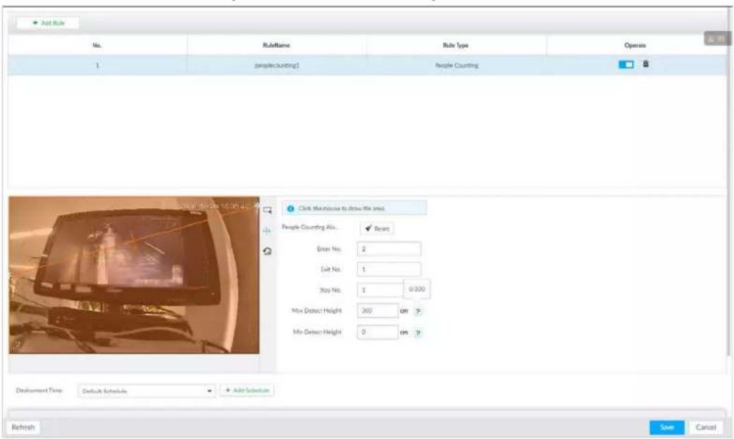
Table 6-12 Parameter description of people counting
| Parameters | Description |
| People Counting Alarm Click | Reset to reset the numbers of entry and exit. |
| Enter No. | Number of people that entered. |
| Exit No. | Number of people that exited. |
| Stay No. | The number of stay is the result of entry number minus exit number. Alarm is triggered when the stay number reaches the threshold. |
| Max Detect Height 0–300. | |
| Min Detect Height 0–300. |
Step 6 Select a schedule in the Deployment Time drop-down list.
Alarms are triggered only within the scheduled time.
Step 7 Click Actions to set alarm linkage actions. See "8.4.1 Alarm Actions" for detailed information.
Step 8 Click Save.
6.4.3 Configuring In Area No.
The system counts the number of people in and out of the detection area. When the number of entry or exit is larger or smaller than the threshold or when the dwell time of any person in the area is greater than the threshold, an alarm is triggered.
Step 1 Click ⚙, click + and then select EVENT.
Step 2 Select a camera in the device tree, and then select AI Application > People Counting > People Counting.
Step 3 Click Add Rule, select In Area No., and then click □ to enable the function.
Step 4 Draw a detection area.
- Click ☐ to draw the detection area.
- Click 🔗 to set the whole image as the detection area.
Figure 6-66 In Area No.
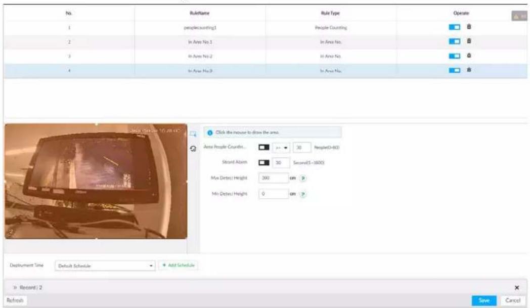
Step 5 Set parameters.
Table 6-13 Parameter description of In Area No.
| Parameters | Description |
| Area People Counting Alarm | 1. Click □ to enable the alarm.2. Set people number threshold.If you select >=▼ and then enter a number, alarm is triggered when the detected number is larger or equal to the number that you entered.If you select <=▼ and then enter a number, alarm is triggered when the detected number is smaller or equal to the number that you entered. |
| Strand Alarm | 1. Click □ to enable the alarm.2. Set time threshold for the alarm. When the dwell time of any person in the area is greater than the threshold, an alarm will be triggered. |
| Max Detect Height 0-300. | |
| Min Detect Height 0-300. | |
Step 6 Select a schedule in the Deployment Time drop-down list.
Alarms are triggered only within the scheduled time.
Step 7 Click Actions to set alarm linkage actions.
Step 8 Click Save.
6.4.4 Configuring Queuing Detection
The system counts the number of people queuing in the detection area. When the number of people exceeds the threshold or the queue time is longer than the pre-defined time, an alarm is triggered.
Step 1 Click 🎨, click +, and then select EVENT.
Step 2 Select a camera in the device tree, and then select AI Application > People Counting > Queuing.
Step 3 Draw a queuing detection area.
1) Click 🔍 to draw the first detection area.
Click 🎨 🎨 🎨 to draw more areas. You can draw 4 areas at most.
2) Click □ to edit the area.
Figure 6-67 Queuing
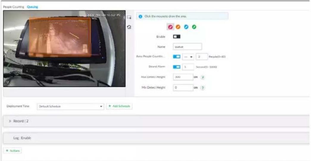
Step 4 Set parameters.
Table 6-14 Parameter description of queuing detection
| Parameters | Description |
| Enable | Click □ to enable the selected area. |
| Name Enter the area name. | |
| Area People Counting Alarm | 1. Click □ to enable the alarm.2. Set people number threshold.If you select and then enter a number, alarm is triggered when the detected number is larger or equal to the number that you entered.If you select and then enter a number, alarm is triggered when the detected number is smaller or equal to the number that you entered. |
| Queuing Time Alarm | 1. Click □ to enable the alarm.2. Set time threshold for the alarm. When the queuing time of any person in the area is longer than the threshold, an alarm will be triggered. |
Step 5 Select a schedule in the Deployment Time drop-down list.
Alarms are triggered only within the scheduled time.
Step 6 Click Actions to set alarm linkage actions.
Step 7 Click Save.
6.4.5 Live View
On the LIVE page, open a view window that contains people counting video.
The live video which shows real-time people number and queuing time is displayed.
Figure 6-68 Live view
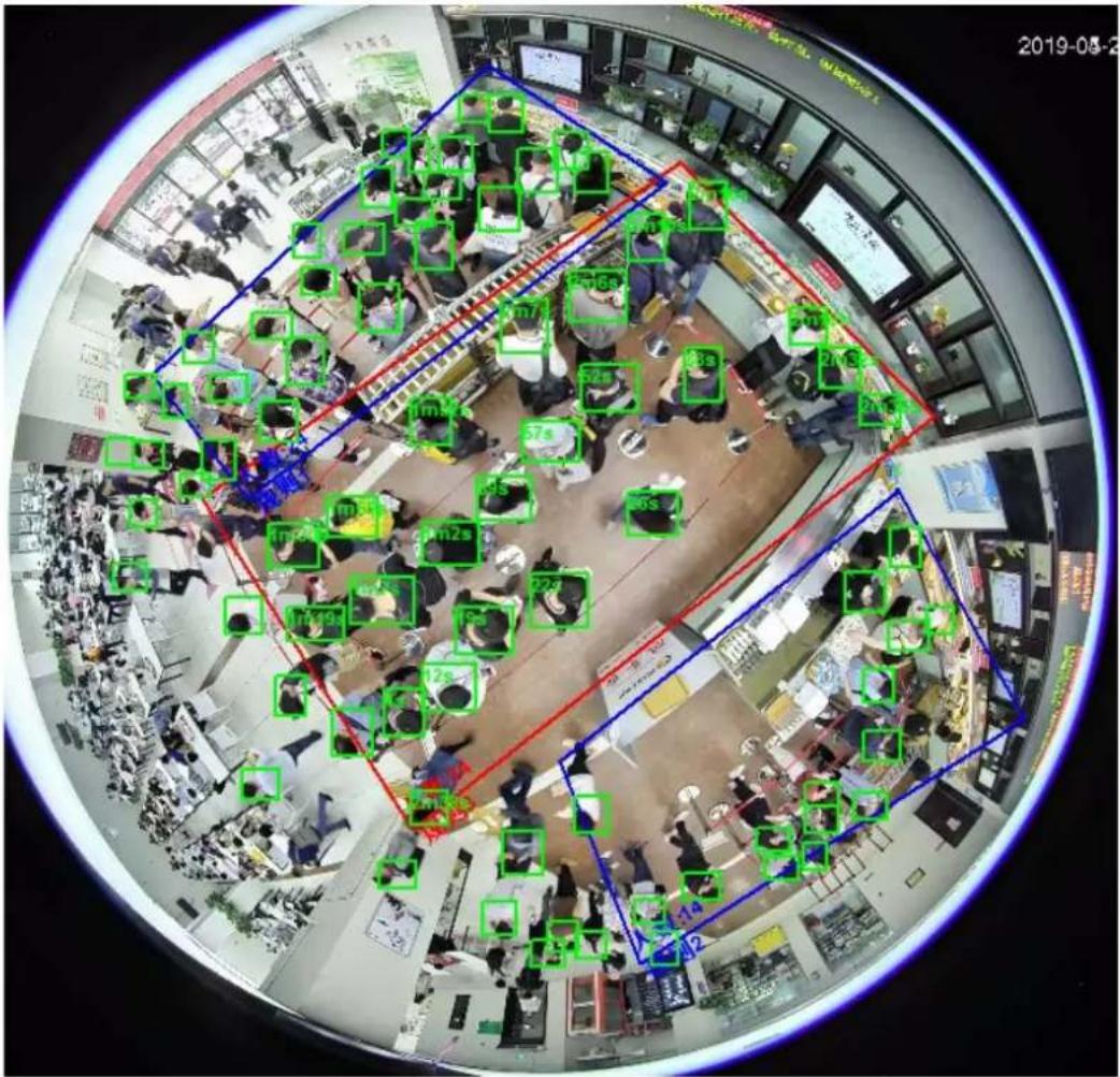
The live video displays real-time people number in the region, and the region frame flashes red once there is an alarm. The queue-detection live view also shows head frames and the dwell time of each person.
6.4.6 Viewing AI Report
Procedure
Step 1 On the LIVE page, click +, and then select AI REPORT > AI REPORT > People Counting.
Step 2 Select a device to be searched. You can only select Al fisheye camera.
Step 3 For Type, select People Counting, In Area People Counting or.
Step 4 Select a statistics type.
- People counting: Select People Counting, and then select the strand time (5 s, 30 s, 60 s).
- Average strand time: The report shows the average strand time during different time periods.
Step 5 Select a time period type from Date, month or year. Daily, Monthly, and Yearly, and then set the corresponding
Step 6 Click OK. The report is displayed.
Figure 6-69 People counting report
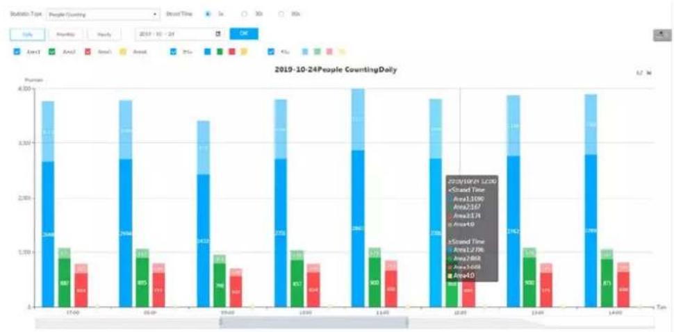
bar_stacked
2019-10-24People CountingDaily | Age Group | 18-34 | 35-54 | 55+ | |---|---|---|---| | 17-49 | 264 | 61 | 1 | | 50-69 | 294 | 71 | 1 | | 70-89 | 241 | 61 | 1 | | 80+ | 178 | 61 | 1 | | 18-34 | 198 | 71 | 1 | | 35-54 | 276 | 71 | 1 | | 55+ | 214 | 71 | 1 | | 18-34 (Mean:1300) | 276 | 71 | 1 | | 35-54 (Mean:2167) | 214 | 71 | 1 | | 55+ (Mean:410) | 276 | 71 | 1 | | 18-34 (Mean:1236) | 276 | 71 | 1 | | 35-54 (Mean:2862) | 214 | 71 | 1 | | 55+ (Mean:3458) | 276 | 71 | 1 | | 18-34 (Mean:4.0) | 276 | 71 | 1 | | 35-54 (Mean:4.0) | 276 | 71 | 1 | | 55+ (Mean:4.0) | 276 | 71 | 1 | The data is presented in a table format with the following columns: 'Age' and 'Counting Daily'. The values are estimated based on the provided code.Figure 6-70 Average strand time report
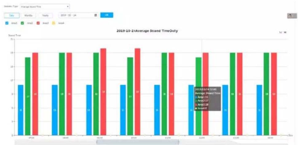
bar
2019-10-24 Average Stand TimeDaily | Week | Area1 | Area2 | Area3 | Area4 | |---|---|---|---|---| | 27:00 | 1.5 | 13.5 | 14.0 | 0 | | 30:00 | 1.5 | 14.0 | 14.0 | 0 | | 33:00 | 1.5 | 14.0 | 14.5 | 0 | | 6:00 | 1.5 | 14.0 | 14.5 | 0 | | 9:00 | 1.5 | 13.5 | 14.5 | 0 | | 12:00 | 1.5 | 14.0 | 14.0 | 0 | | 15:00 | 1.5 | 14.0 | 14.0 | 0 | | 18:00 | 1.5 | 14.0 | 14.0 | 0 | | 21:00 | 1.5 | 13.5 | 14.0 | 0 | | 24:00 | 1.5 | 14.0 | 14.0 | 0 | | 27:00 | 1.5 | 14.0 | 14.0 | 0 | The data is already in CSV format with the following columns and contains no additional data series or trends for any specific area categories. The values are estimated based on the date and the average stand time.Figure 6-71 Queuing people counting report
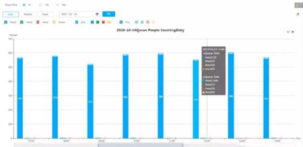
bar
2019-10-24Queue People CountingDaily | Time | Number of Users | | :--- | :--- | | 07:00 | 58 | | 08:00 | 56 | | 09:00 | 53 | | 10:00 | 58 | | 11:00 | 59 | | 12:00 | 54 | | 13:00 | 60 | | 14:00 | 55 |- Click ✅ Area1 ✅ Area2 ✅ Area3 ✅ Area4 to select the areas of which you need to view the reports. The ordinate of the report displays different areas in different colors, showing the number of people in different areas or the average strand time.
- For people counting report, click Strand Time 5s 30s 60s to select a strand time. The report shows the people numbers of which the strand time is greater or less than the selected strand time.
- Point to the report, and then the report shows the details at that time point.
- Drag the gray scroll bar under the ordinate to view the statistics for different time periods.
- Click 📋 to view the line chart.
- Click 📁 to view the bar chart.
- Click to export the report.
6.5 Video Metadata
The system analyzes real-time video stream to detect the existence of 4 target types: human, human face, motor vehicle, non-motor vehicle. Once a target is detected, the system can record video, take snapshots and trigger alarms.
This section introduces how to configure the video metadata feature from enabling it and selecting target types to setting the live view of video metadata.
6.5.1 Enabling AI Plan
Enable AI plan when AI by camera is used. See "6.2.1 Enabling AI Plan" to enable video metadata function.
6.5.2 Configuring Video Metadata
After enabling video metadata, the Device links the current remote device to record video when alarm is triggered.

- The Device supports metadata by camera (AI by Camera on the page) or by the Device (AI by Device on the page). This section uses metadata by the Device for example to introduce the configuration procedure.
- Video metadata cannot be enabled at the same time with face detection and IVS, because it conflicts with the two functions.
Step 1 Click 🎨 or +, and then select EVENT.
Step 2 Select a device from the device tree at the left side.
Step 3 Select AI Application > Video Metadata > AI by Device.
Figure 6-72 AI by camera
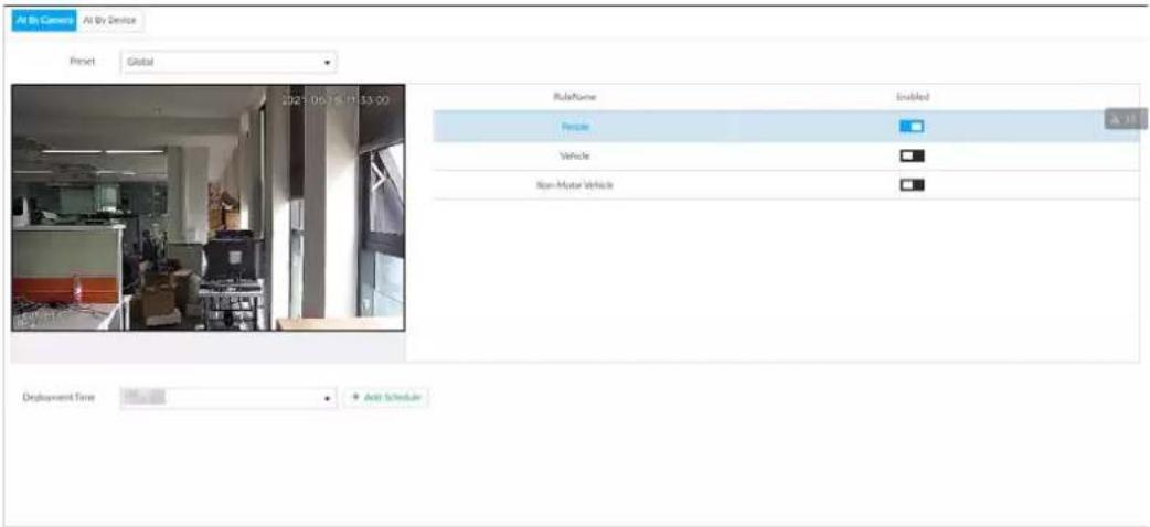
Figure 6-73 AI by device
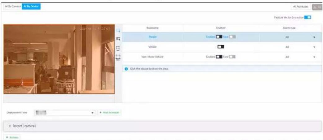
Step 4 Click □ next to Feature Vector Extraction to enable feature extraction, and then the Device can extract features of human, vehicles and non-motor vehicles and display them on the live view. The search by image function is available only when feature vector extraction is enabled.
Step 5 Select the detection target.
- People: Click next to Enabled to enable people detection. Face detection can also be enabled at the same time.
- Vehicle: Click corresponding □ to enable vehicle detection.
- Non-Motor Vehicle: Click corresponding □ to enable non-motor vehicle detection.
Step 6 Select alarm type.
- All: An alarm is triggered when a target is detected.
- Match Attributes Alarm: An alarm is triggered when the detected target matches the defined attributes.
- Mismatch Attributes Alarm: An alarm is triggered when the detected target does not match the defined attributes.

You can select alarm type only when AI by device is used.
Step 7 Click ☐ (the icon changes to ☐), and then you can configure detection area (orange) in the video image.
- Click any white dot on the frame, and the dot changes to .
- Drag ✗ to adjust the detection area.
- Click 📄 to draw an excluded area which will not be detected. The Device does not detect target within the excluded area.
- Click ☐ or ☐ to set the minimum size or maximum size of the face detection area. System triggers an alarm once the size of detected target is between the maximum size and the minimum size.

You can configure detection area only when AI by device is used.
Figure 6-74 Detection area
natural_image
Pixelated interior scene with orange horizontal stripe and floor, no readable text or symbolsStep 8 Click Deployment Time drop-down list to select schedule.
The Device links alarm event when an alarm is triggered within the schedule configured.
- Click Add Schedule to add new schedule if no schedule is added or the existing schedule does not meet requirements. For details, see "8.8.4 Schedule".
- Click View Schedule to view details of schedule.
Step 9 Click Actions to set alarm linkage actions. See "8.4.1 Alarm Actions" for detailed information.

You can set alarm linkage actions only when AI by device is used.
Step 10 Click Save.
6.5.3 Live View of Video Metadata
View the detection results of face, people, motor vehicle and non-motor vehicle on the LIVE page.
6.5.3.1 Setting AI Display
Set the filtering conditions to display AI detection results.

Create view(s) before setting filtering conditions. To create a view, see "7.1.1 View Management".
Step 1 Select a view from LIVE > View > View Group.
Step 2 Click ☑ at the lower side of the LIVE page, and then select Face, Human, Vehicle or Non-Motor Vehicle.

The figure uses Human for example and is for reference only.
Figure 6-75 Human
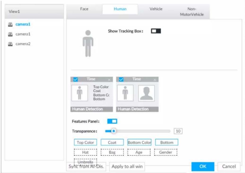
Step 3 Click □ next to Show Tracking Box, and then a tracking box is displayed in the video when target that meets the filtering conditions is detected.
Step 4 Configure feature panel.
1) Click □ next to Features Panel to enable feature panel.
2) A features panel is displayed on the right side of the video when target that meets the conditions is detected.
3) Click □ to select the panel type, for example, the Human Detection tab.
4) (Optional) Drag ☐ to adjust the transparency of panel. The higher the value is, the more transparent the panel will be.
5) (Optional) Select the features to be displayed in the panel.
- Up to 4 features can be displayed.
- 4 features are selected by default. To select another feature, click the selected feature to cancel it, and then click the feature to be displayed.
Step 5 Click OK.
6.5.3.2 Live View
On the LIVE page, select a view from View Group, and the video image of the view will be displayed.
- Rule box is displayed in real-time in the video image. Different detection targets correspond to different colors of rule box.
- Features panels are displayed on the right side of the video image.
Figure 6-76 Live
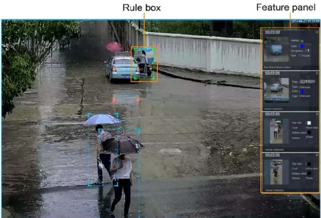
Point to the features panel, and the icons are displayed.
Figure 6-77 Icons (vehicle detection)
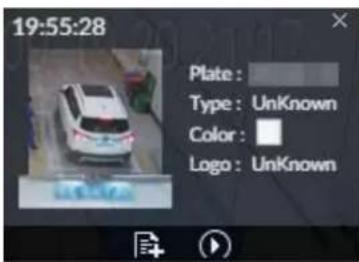
- Click 📄 to add plate information to plate database.
- Click 📋 or double-click the detected image to play back the video record (10 s before and after the snapshot).
- Click to search for similar targets in the history videos.
6.5.3.3 Detection Statistics
View the detection statistics of human, motor vehicle and non-motor vehicle.
6.5.3.3.1 Human
On the LIVE page, click .
Click ☐, and then select Snap With Face and Snap Without Face. The information of detected human and face is displayed.
Figure 6-78 Human detection
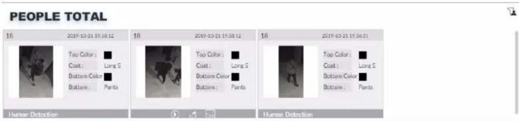
- Point to the snapshot, and then click 📄 to add the face image to face database. For details, see "6.3.3.4.3 Adding Face Image".

This function is available when face image is captured.
- Point to the snapshot, and then click 📋 or double-click the picture to play back the video record (10 s before and after the snapshot).
- Point to the snapshot, and then click 📋 to export the video record to specified saving path.
- Point to the snapshot, and then click 📋 to search for similar targets in the snapshot records.

Make sure that USB storage device is connected during local operation.
6.5.3.3.2 Motor Vehicle
On the LIVE page, click 📄, the VEHICLE TOTAL page is displayed.
Click, and then select Vehicle Recognition, the information of detected vehicles is displayed.
Figure 6-79 Motor vehicle detection
VEHICLE TOTAL

- Point to the panel, and then click 📄 to add the license plate image to plate database. For details, see "6.8.3.2.3 Adding from Detection Results".
- Point to the panel, and then click 📋, or double-click detected picture to play back the video record (10 s before and after the snapshot).
- Point to the panel, and then click 📋 to export the video record to specified saving path.

Make sure that USB storage device is connected during local operation.
6.5.3.3.3 Non-motor Vehicle
On the LIVE page, click 🎨
Click, and then select Snap With Face and Snap Without Face. The information of detected non-motor vehicles is displayed.
Figure 6-80 Non-motor vehicle detection
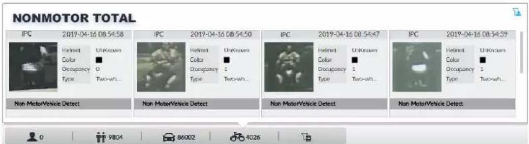
- Point to the detected information, and then click 📋, or double-click detected picture to play back the video record (10 s before and after the snapshot).
- Point to the detected information, and then click 🔒 to export the video record to specified saving path.

Make sure that USB storage device is inserted during local operation.
- Point to the snapshot, and then click 📋 to search for similar targets in the snapshot records.

appears on the panel of the non-motor vehicle snapshot that contains a human face.
6.5.4 AI Search
Select device and set properties to search for detection results.
6.5.4.1 Human Search
Select device and set human properties to search human detection results.
6.5.4.1.1 Searching by Property
Procedure
Step 1 On the LIVE page, click +, and then select AI SEARCH > Search by Human.
Figure 6-81 Search by human
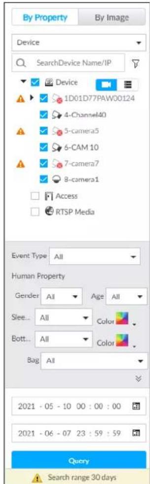
Step 2 Select one or more devices, and then select Human Detection as Event Type.
Step 3 Select alarm type.
Step 4 Set human properties and time period.
Click or to set the color. means more than one color.
Step 5 Click Query.
- If face is captured, the human and face snapshots are displayed.
- If no face is captured, the human snapshot and human properties are displayed.
Figure 6-82 Search result
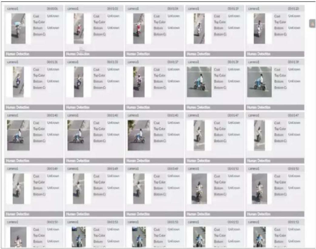
Related Operations
Click one displayed panel, and the icons are displayed.
Figure 6-83 Icons (1)
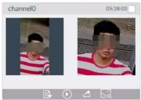
Figure 6-84 Icons (2)
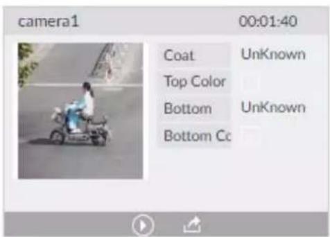
Table 6-15 Operation
| Icon | Operation |
| Select one by one: Click to select the panel.√ means the panel is selected.Select in batches: Select All to select all the panels on the page. | |
| Click or double-click the panel to play back the video record (10 s before and after the snapshot). | |
| Click to add picture to database. See "6.3.3.4.3 Adding Face Image". | |
| Export one by one: Click to export picture, video and video player. For details, see "6.2.4.3 Exporting Face Records".Export in batches: Select the panel and click ↗ to export picture, video and excel. For details, see "6.2.4.3 Exporting Face Records".After setting alarm linkage snapshot, during exporting images, the system exports detected images and panoramic images at the time of snapshot. | |
| Click to search for similar targets in the snapshot records. |
6.5.4.1.2 Searching by Image
Upload human body pictures to search for similar targets.

The search by image function is only available when feature vector extraction is enabled. For details, see Step 4 in "6.5.2 Configuring Video Metadata".
Searching Devices
Upload human body pictures to search the specific devices for similar targets.
- On the LIVE page, click +, and then select AI SEARCH > Search by Human > By Image.
Figure 6-85 Search by image
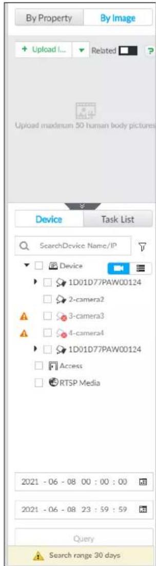
- Click the Device tab.
- Upload a picture.
Upload from PC or USB storage device.

Up to 50 pictures can be uploaded. Up to 10 pictures can be uploaded at a once.
a. Point to + Upload Image ▼, and then select Local.
b. Select one or more pictures.
c. Click OK.
After the upload is completed, the uploaded picture is shown at the upper-left corner of the page. The latest 10 pictures are displayed by default.

Up to 10 pictures can be selected at the same time.
- Click ☐ to enable related search. If related search is enabled, the system searches for both face detection results and human detection results.
Figure 6-86 Related search
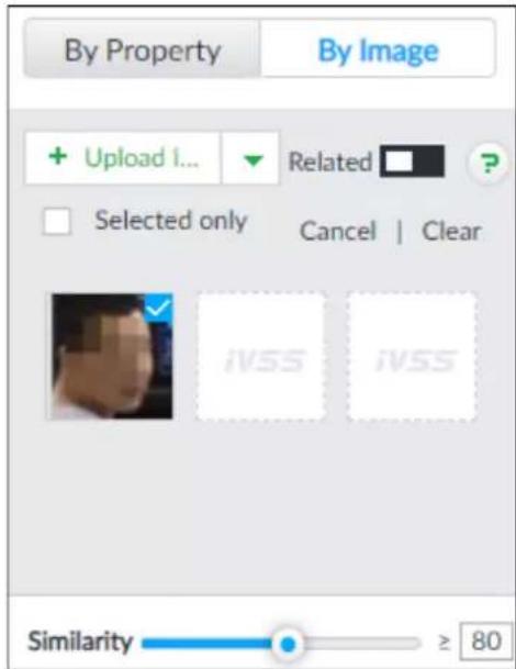
- Set similarity. It is 80% by default.
- Select a remote device in the device list, and then set search time.
- Click Query.
Searching Task List
Upload a human body picture search the analyzed video for similar targets. For details about AI tasks, see "7.4.1 AI Analysis Task".
- On the LIVE page, click +, and then select AI SEARCH > Search by Human > By Image.
- Click Task List.
Figure 6-87 Task list
![By Property By Image + Upload I... Related Upload maximum 50 human body pictures. Device Task List All Search All fa_20210601112418_2021c rtyghgh10311103733_2021 renlian1234567[0].dav qwer zxcvb camera3_20210602141428_ IPC zhanhui[0].dav jidongche[0].dav 6123456 IPC_20210601140351_202; 2 Query](/content/2026/05/1061580/images/4edc716bf85d07a77afee50afbff98b27530b3e19483830151c65630d47dd4e0.jpg)
- Upload a human body picture. For details, see step 3 in "6.2.4.2.1 Searching Devices".
- Click ☐ to enable related search. If related search is enabled, the system searches for both face detection results and human detection results.
Figure 6-88 Related search
- Set similarity. It is 80% by default.
- Select a task to be searched.
- Click Query.
Managing Search Results
Figure 6-89 Search results
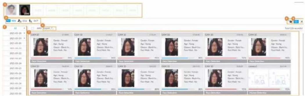
Table 6-16 Search results page description
| No. | Function |
| 1 | Displays the selected search images. The number at the lower-right corner of the image represents the number of records found.Click the image to view detailed results. |
| 2 | :displays the number of images found.:Displays the number of face images found.:Displays the number of human body images found.The numbers are displayed only when related search is enabled. |
| 3 | Displays the dates within the selected search range.Click a date and the records of that day are displayed. |
| 4 | Select the panel and click to export picture, video or excel. For details, see "6.2.4.3 Exporting Face Records". |
| 5 Filter the search results according to properties. | |
| 6 | : Sort the records by time.: Sort the records by similarity. |
| 7 | Displays the face panels, including face image, feature property and similarity. |
6.5.4.2 Vehicle Search
Set event type and vehicle properties to search vehicle detection results.
Step 1 On the LIVE page, click + and then select AI SEARCH > Search by Vehicle.
Step 2 Select device, and then click Property tab.
Figure 6-90 Property
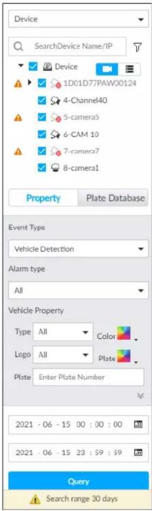
Step 3 Select Vehicle Detection as Event Type.
Step 4 Select alarm type.
Step 5 Set vehicle properties and time period.
Step 6 Click or to set the color. means more than one color.
Step 7 Click Query.
The search results are displayed.
If license plate is detected, both the scenario and the license plate will be displayed.
Figure 6-91 Search result
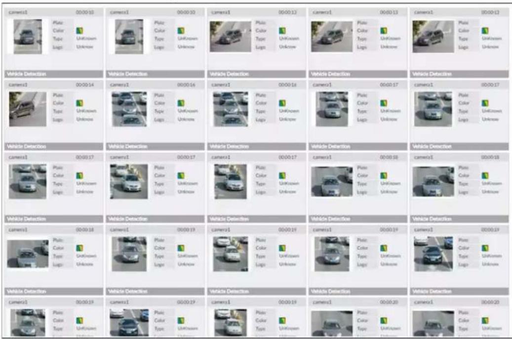
Click one displayed panel, and the icons are displayed.
Figure 6-92 Icons
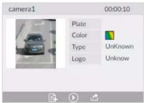
Table 6-17 Operation
| Icon | Operation |
| Select one by one: Click to select the panel.√ means the panel is selected.Select in batches: Select All to select all the panels on the page. | |
| Click or double-click the panel to play back the video record (10 s before and after the snapshot). | |
| Click to add picture to database. See "6.3.3.4.3 Adding Face Image".Export one by one: Click to export picture, video and video player. For details, see "6.2.4.3 Exporting Face Records".Export in batches: Select the panel and click to export picture, video or excel. For details, see "6.2.4.3 Exporting Face Records".After setting alarm linkage snapshot, during exporting images, the system exports detected images and panoramic images at the time of snapshot. |
6.5.4.3 Non-motor Vehicle Search
Set event type and non-motor vehicle properties to search non-motor vehicle detection results.
Step 1 On the LIVE page, click +, and then select AI SEARCH > Search by NonMotor.
Figure 6-93 Search by non-motor vehicle
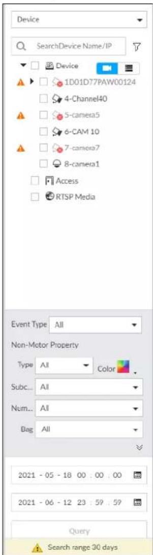
Step 2 Select the device you want to search.
Step 3 Select Non-motor Vehicle as Event Type.
Step 4 Select alarm type.
Step 5 Set non-motor vehicle properties and time period.
Step 6 Click or to set the color. means more than one color.
Step 7 Click Query.
Figure 6-94 Search results
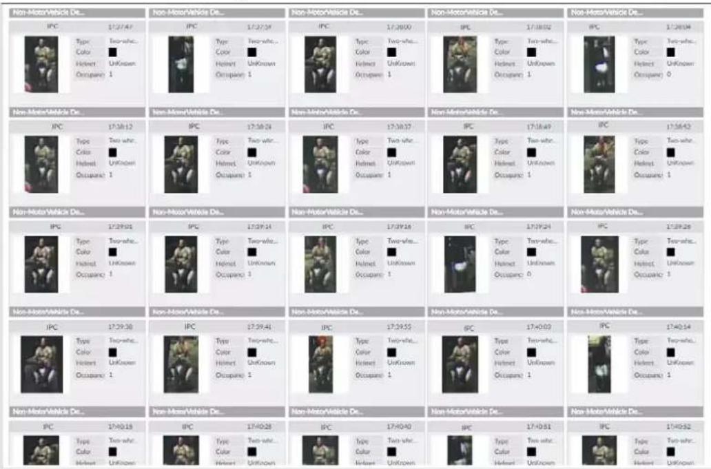
Figure 6-95 Icons
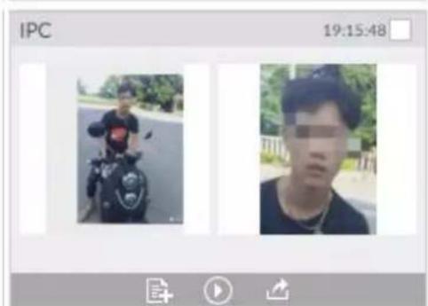
Table 6-18 Operation
| Icon | Operation |
| Select one by one: Click to select the panel.means the panel is selected.Select in batches: Select All to select all the panels on the page. | |
| Click or double-click the panel to play back the video record (10 s before and after the snapshot). | |
| Export one by one: Click to export picture, video and video player. For details, see "6.2.4.3 Exporting Face Records".Export in batches: Select the panel and click to export picture, video or excel. For details, see "6.2.4.3 Exporting Face Records".After setting alarm linkage snapshot, during exporting images, the system exports detected images and panoramic images at the time of snapshot. | |
| Click to add picture to database. See "6.3.3.4.3 Adding Face Image". | |
| Click to search for similar targets in the snapshot records. |






-18 Operation
-18 Operation
-18 Operation
-18 Operation
-18 Operation
-18 Operation
-18 Operation
-18 Operation
-18 Operation
-18 Operation
-18 Operation
-18 Operation
-18 Operation
-18 Operation
-18 Operation
5-18 Operation
-18 Operation
-18 Operation
-18 Operation
-18 Operation
-18 Operation
-18 Operation
-18 Operation
| -18 Operation |
-18 Operation
-18 Operation
-18 Operation
-18 Operation
-18 Operation
-18 Operation
-18 Operation
-18 Operation
-18 Operation
-18 Operation
-18 Operation
-18 Operation
-18 Operation
-18 Operation
5-18 Operation
-18 Operation
-18 Operation
-18 Operation
-18 Operation
-18 Operation
-18 Operation
| -18 Operation |
-18 Operation
-18 Operation
-18 Operation
-18 Operation
-18 Operation
-18 Operation
-18 Operation
-18 Operation
-18 Operation
-18 Operation
-18 Operation
-18 Operation
-18 Operation
-18 Operation
-18 Operation
-18 Operation
-18 Operation
-18 Operation
-18 Operation
-18 Operation
-18 Operation
-18 Operation
-18 Operation
-18 Operation
-18 Operation
-18 Operation
-18 Operation
-18 Operation
-18 Operation
| -18 Operation |
-18 Operation
-18 Operation
-18 Operation
-18 Operation
-18 Operation
6-18 Operation
-18 Operation
-18 Operation
-18 Operation
-18 Operation
-18 Operation
-18 Operation
-18 Operation
-18 Operation
6.6 IVS
The IVS feature includes a number of behavior detections such as fence-crossing, intrusion, tripwire, parking, crowd gathering, missing object, abandoned object, and loitering. You can configure alarm notifications of those intelligent detections.
This section introduces how to configure the intelligent detections.

Some device models only support some IVS functions by device.
6.6.1 Enabling AI Plan
Enable AI plan when AI by camera is used. See "6.2.1 Enabling AI Plan" to enable AI detect function.
6.6.2 Configuring IVS
Configure IVS model and rules.
6.6.2.1 Switching IVS Model
This function is only effective to AI by Device.
Step 1 Click 🎨, or click + on the configuration page, and then select EVENT.
Step 2 Select the root node in the device tree on the left.
Step 3 Select AI Application > IVS Module Switch.
Step 4 Select a model as you need.
Figure 6-96 Switch IVS model

- General model: Supports only tripwire and intrusion.
- Advanced model: Supports tripwire, intrusion, people gathering, parking detection, and loitering.

- The Advanced Model includes more detections but supports fewer channels.
- You need to configure IVS AI-by-Device event again after switching IVS model.
6.6.2.2 Global Configuration
Configure global rules of IVS, including anti-disturbance and sensitivity settings.

Global configuration is needed only when AI by camera is used.
Step 1 Click 🎨, or click + on the configuration page, and then select EVENT.
Step 2 Select a device in the device tree on the left.
Step 3 Select AI Application > IVS > AI By Camera > Global Config.
Figure 6-97 Global config
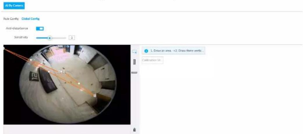
Step 4 Configure anti-disturbance and sensitivity settings.
- Click □ to enable anti-disturbance function.
- Drag to adjust sensitivity.
Step 5 Calibrate horizontal and vertical scales.
1) Click □ to draw an area.
2) Click [] to draw three vertical lines, enter the actual length, and then click Calibration Verification.
3) Click 📄 to draw a horizontal line, enter the actual length, and then click Calibration Verification.
Step 6 Click Save.
6.6.2.3 Rule Configuration
Configure IVS rules. IVS functions are different between AI by camera and AI by device.
- IVS functions with AI by camera: Crossing fence, tripwire, intrusion, abandoned object, parking detection, people gathering, object removed, and loitering. Different cameras support different functions.
- IVS functions with AI by device differ depending on the IVS model.
◇ General model: Supports only tripwire and intrusion.
Advanced model: Supports tripwire, intrusion, people gathering, parking detection, and loitering.
Table 6-19 IVS functions description
| Functions | Description | Scene |
| Tripwire | When the target crosses tripwire from the defined motion direction, an alarm is triggered, and then the system performs configured alarm linkages. | Scenes with sparse targets and no occlusion among targets, such as the perimeter protection of unattended area. |
| Intrusion | When the target enters, leaves, or appears in the detection area, an alarm is triggered, and the system performs configured alarm linkages. | |
| Abandoned Object | When an object is abandoned in the detection area over the configured time, an alarm is triggered, and then the system performs configured alarm linkages. | Scenes with sparse targets and without obvious and frequent light change.Simple scene in the detection area is recommended.Missed alarm might increase in the scenes with dense targets, frequent occlusion, and people staying.In scenes with complex foreground and background, false alarm might be triggered for abandoned or missing object. |
| Missing Object | When an object is taken out of the detection area over the defined time, an alarm is triggered, and then the system performs configured alarm linkages. | |
| Fast Moving | When the target moves fast in the detection area, an alarm is triggered, and then the system performs configured alarm linkages. | Scene with sparse targets and less occlusion. The camera should be installed right above the monitoring area. The light direction should be vertical to the motion direction. |
| Parking Detection | When the vehicle stays in the detection area longer than the configured duration, an alarm is triggered, and then the system performs configured alarm linkages. | Road monitoring and traffic management. |
| Crowd Gathering | When people gather and stay in the detection area longer than the defined duration, an alarm is triggered, and then the system performs configured alarm linkages. | Scenes with medium or long distance, such as outdoor plaza, government entrance, station entrance and exit. It is not suitable for short-distance view analysis. |
| Loitering | When the target loiters over the shortest alarm time, an alarm is triggered, and then the system performs configured alarm linkages. | Scenes such as park and hall. |
| Crossing Fence | When the target crosses the warning line toward the defined direction, an alarm is triggered and then the system performs configured alarm linkages. | Scenes with median strips such as roads, and airports. |
This section uses the configuration of tripwire as the example.
Step 1 Click ⚙, or click + on the configuration page, and then select EVENT.
Step 2 Select remote device in the device tree on the left.
Step 3 Select AI Application > IVS. Click AI by Camera or AI by Device.
Figure 6-98 AI by camera
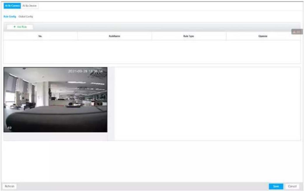
Figure 6-99 AI by device
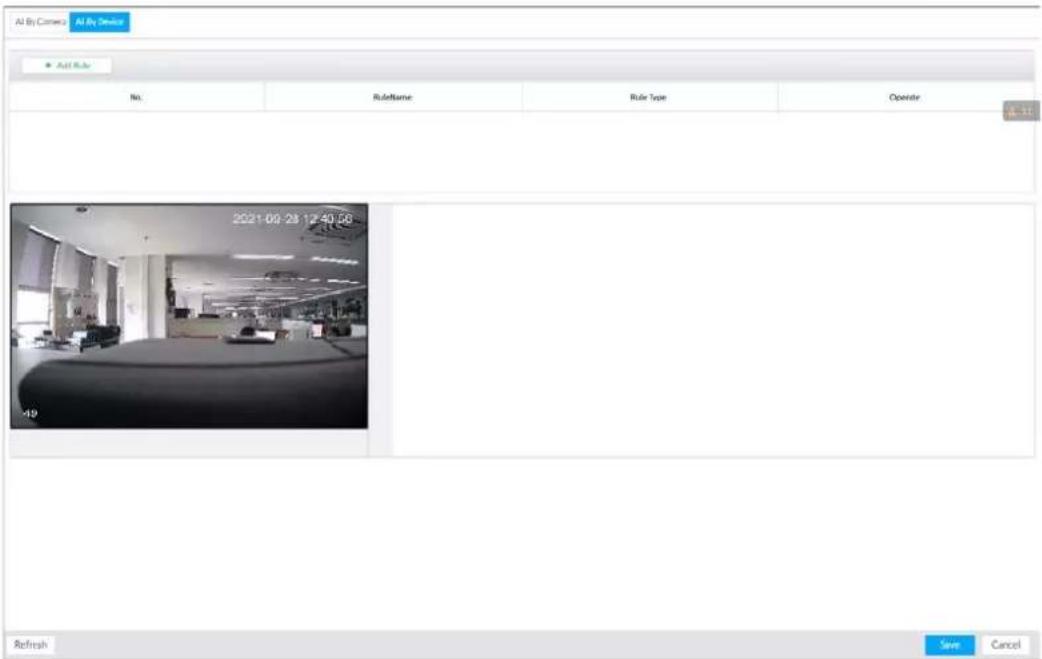
Step 4 Set tripwire rules.
1) Click Add Rule, and then select Tripwire.
2) Click □ to enable detection rule.
Click to delete detection rule.
3) Click ← to edit the tripwire line.
- Drag ✗ to adjust position or length of the line.
- Click ☐ or ☒ to set the directions. An alarm will be triggered only when the target crosses the line in the designated direction.
- Click the white dot on the line to add a turning point. Drag ✗ at the turning point to adjust position or length.
Figure 6-100 Configure tripwire detection rules
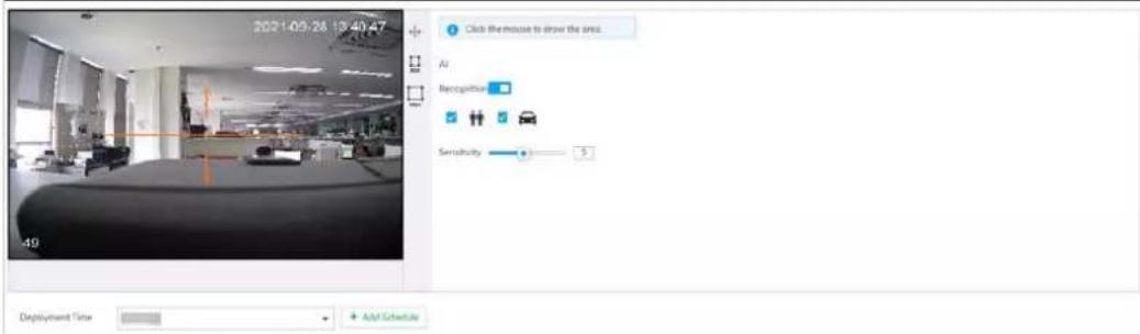
4) Click ☐ or ☐ to set minimum size or maximum size of detection target.
System triggers an alarm once the detected target size is between the maximum size and the minimum size.
Step 5 Configure AI recognition and sensitivity.
After setting AI recognition, when the system detects a person, vehicle or non-motor vehicle, a rule box will appear beside the target on the video.
1) Click □ to enable AI recognition function.
Figure 6-101 Type
2) Select a recognition type.
• is to recognize human, and 📁 is to recognize vehicle.
- After enabling AI recognition function, you need to select at least one recognition type.
3) Configure sensitivity.
The higher the sensitivity, the easier to trigger tripwire alarm, but meanwhile the higher probability of false alarm.

Sensitivity is available when AI by device is used or when AI by camera is used and the camera supports this function.
Step 6 Click Deployment Time to select schedule from the drop-down list.
After setting deployment period, system triggers corresponding operations when there is a motion detection alarm in the specified period.

If the schedule is not added or the added schedule does not meet actual needs, click Add Schedule.
Step 7 Click Actions to set alarm action. See "8.4.1 Alarm Actions" for detailed information.
Step 8 Click Save.

Repeat Step 4 through Step 8 to add multiple detection rules. You can add max. 10 detection rules at the same time.
6.6.3 Live View of IVS
On the LIVE page, view real-time IVS results.
6.6.3.1 Setting AI Display
Set the display rules of detection results.

Make sure that view is created before setting AI display. To create view, see "7.1.1 View Management".
Step 1 Select a view from LIVE > View > View Group.
Step 2 Click ☑, and then select the Human, Vehicle or Non-Motor Vehicle tab.
Figure 6-102 Human
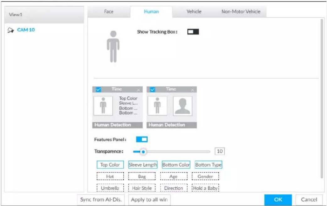
Figure 6-103 Vehicle
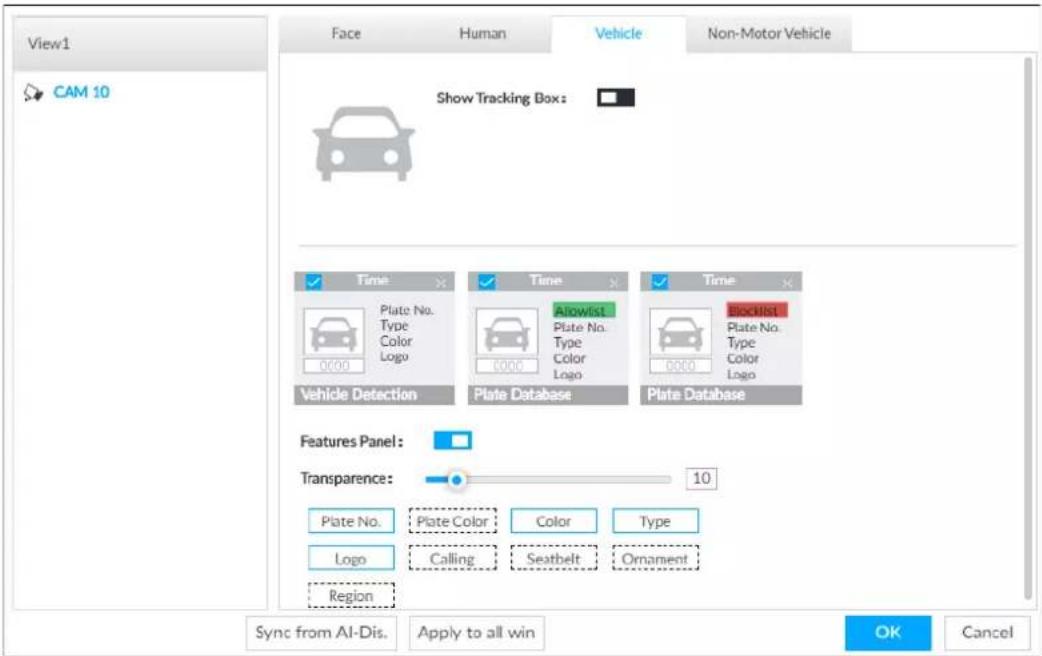
Figure 6-104 Non-motor vehicle
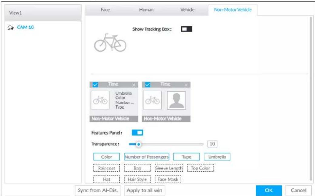
Step 3 Configure feature panel.
1) Click □ next to Features Panel to enable feature panel.
2) A features panel is displayed on the right side of the video when a target that meets the conditions is detected.
3) Click ☐ to select the panel type, for example, the Human Detection tab.
4) (Optional) Drag ☐ to adjust the transparency of panel. The higher the value, the more transparent the panel.
5) (Optional) Select the features to be displayed in the panel.
- Up to 4 features can be displayed.
- 4 features are selected by default. To select another feature, click the selected feature to cancel it, and then click the feature to be displayed.
Step 4 Click OK.
6.6.3.2 Live View
Go to the LIVE page, enable view, and then the Device displays view video.
- When a target triggers cross line or cross region rule, the line or region frame in the view flickers in red.
- After setting AI recognition, when the system detects a person or vehicle, a rule frame will appear beside the person and vehicle in the view.
- There is a feature panel on the right side of the video window.
Figure 6-105 Live
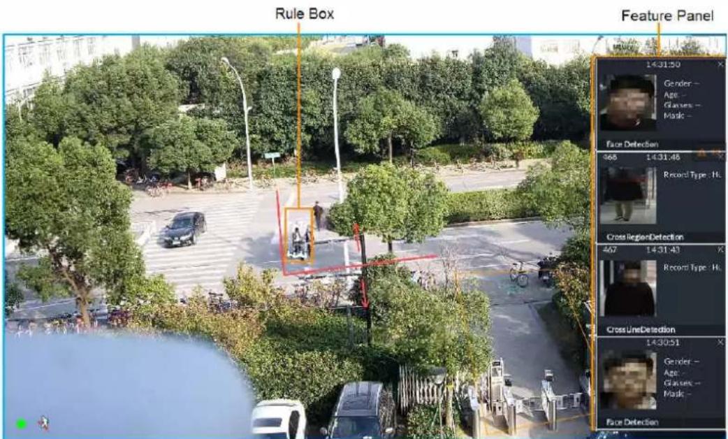
Point to features panel, and the operation icons are displayed.
- Click 📋 or double-click the detected image, so the system starts to play back the recorded videos (10 s before and after the snapshot).
- Click to search for similar faces.
6.6.3.3 Detection Statistics
On the LIVE page, click 🎯. The PEOPLE TOTAL window is displayed. Click 🔒, and then select IVS.
Figure 6-106 People total
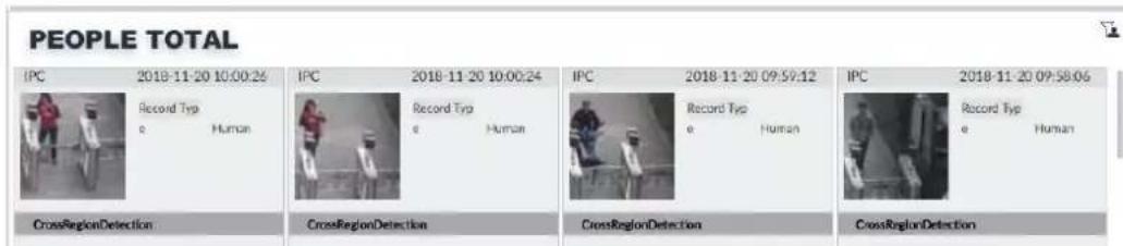
Click 📄. Click 🔒, and then select IVS. The detected vehicles are displayed.
Figure 6-107 Vehicle total
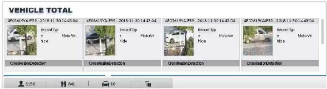
- Point to a picture and click 📋, or double-click the picture, so the system starts playing back video (10 s before and after the snapshot moment).
- Point to a picture and click 📋 to export video and picture.

Make sure that USB storage device is connected during local operation.
On the LIVE page, click 📄. The NON-MOTOR VEHICLE TOTAL window is displayed. Click 📋, and then select IVS. The detected non-motor vehicles are displayed.
- Point to a picture and click 📋, or double-click the picture, so the system starts playing back video (10 s before and after the snapshot moment).
- Point to a picture and click 📋 to export video and picture.
6.6.4 IVS Search
Search for IVS records.
Step 1 On the LIVE page, click + and then select AI SEARCH > IVS.
Step 2 Select the remote device, and set event type, effective target and time.
Step 3 Click Query.
Figure 6-108 Search result
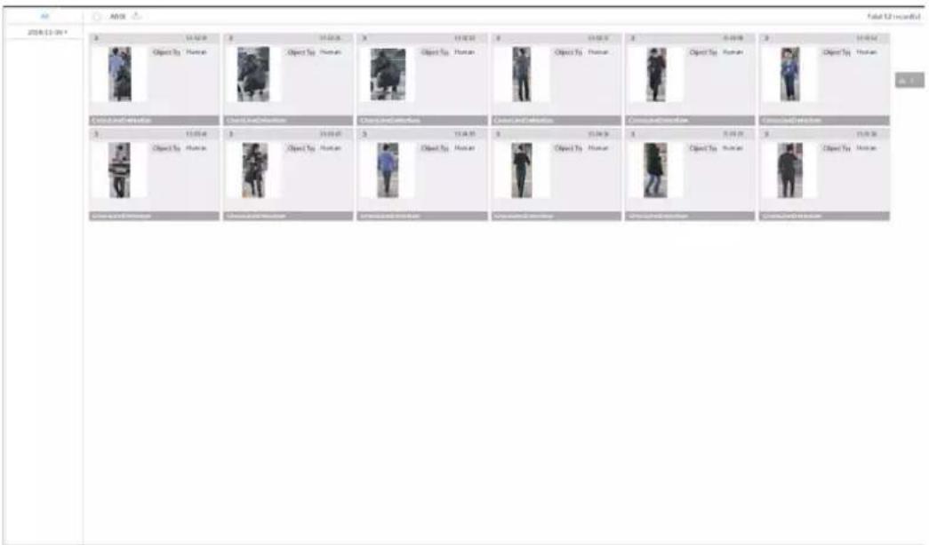
Click the panel. The following operation icons are displayed.
Table 6-20 More operations
| Name | Operation |
| Select a panel | Select one by one: Move the mouse pointer onto the panel. Click to select the panel.√ means it is selected.Click ALL to select all the panels. |
| Playback | Click the panel, and click 📋 or double-click the panel. The system starts to play back the recorded videos (10 s before and after the snapshot). |
| Export file | Export one by one: Click 🔔 to export picture, video and video player. For details, see "6.2.4.3 Exporting Face Records".Export in batches: Select the panel and click 🔊 to export picture, video or excel. For details, see "6.2.4.3 Exporting Face Records". |
6.7 Vehicle Recognition
Alarm is triggered when vehicle property that meets detection rule is detected.

The Device supports only vehicle recognition through AI by camera. Make sure that the vehicle recognition parameters of camera are configured. For details, see the user's manual of the camera.
6.7.1 Enabling AI Plan
Before using AI by camera, AI plan needs to be enabled first. For details, see "6.2.1 Enabling AI Plan".
6.7.2 Setting Vehicle Recognition
Set the deployment time of vehicle recognition and alarm linkage event.
Step 1 Click 🎨 or +, and then select EVENT.
Step 2 Select device from the device tree at the left side.
Step 3 Select AI Application > Vehicle Recognition.

AI by camera is enabled by default and cannot be disabled.
Figure 6-109 Vehicle recognition
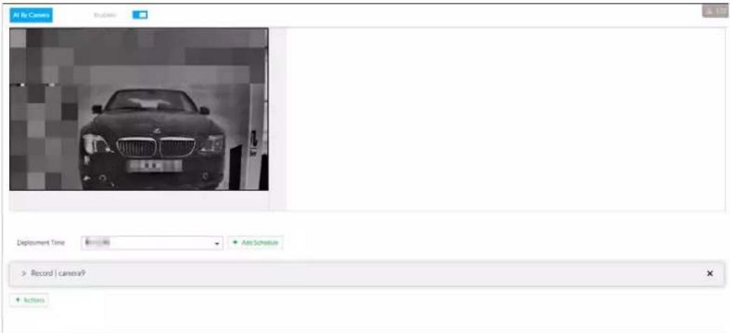
Step 4 Click the Deployment Time drop-down list to select schedule.
IVSS links alarm event when alarm is triggered within the defined schedule.
- Click View Schedule to view detailed schedule settings.
- If the schedule is not added or the added schedule does not meet actual needs, click Add Schedule. For details, see "8.8.4 Schedule".
Step 5 Click Actions to set alarm action. For details, see "8.4.1 Alarm Actions".
Step 6 Click Save.
6.7.3 Live View of Vehicle Recognition
View vehicle recognition results on the LIVE page.
6.7.3.1 Setting AI Display
Set the display rules of detection results.

Make sure that view is created before setting AI display. To create view, see "7.1.1 View Management".
Step 1 Select a view from LIVE > View > View Group.
Step 2 Click ☐, and then select Vehicle tab.
Figure 6-110 Motor vehicle
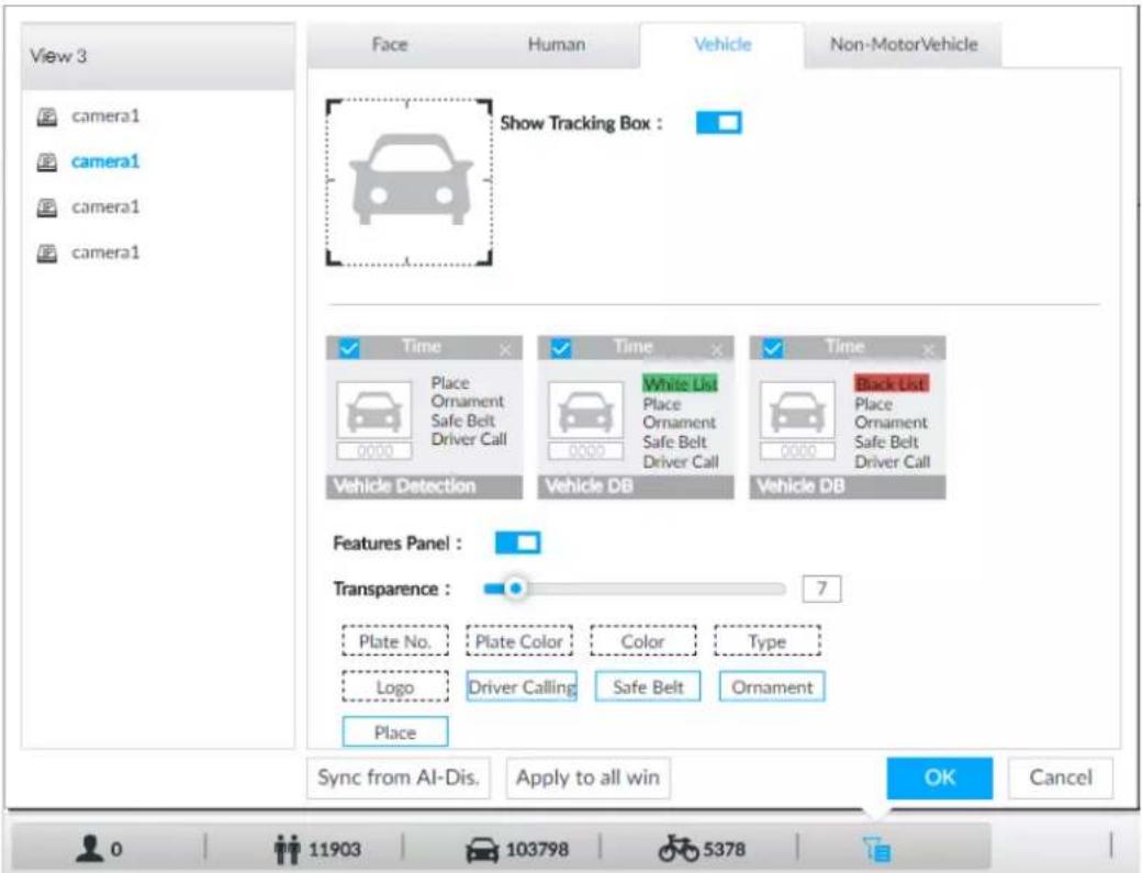
Step 3 Click □ next to Show Tracking Box to enable tracking box function.
A tracking box is displayed in the video image when target meeting detection rule is detected.
Step 4 Set features panel.
1) Click □ next to Features Panel to enable features panel function.
2) Features panel will be displayed at the right side of video image when target with selected features is detected.
3) Select the Vehicle Detection panel type by clicking ☐. √ means the panel is selected.
4) (Optional) Drag ☐ to adjust the transparency of panel. The higher the value, the more transparent the panel.
5) (Optional) Select the features to be displayed in the panel.
- Up to 4 features can be displayed.
- 4 features are selected by default. To select another feature, click the selected feature to cancel it, and then click the feature to be displayed.
Step 5 Click OK.
6.7.3.2 Live View
On the LIVE page, select a view, and the video image of the view is displayed.
- Tracking box is displayed in the video image.
- Features panel is displayed at the right side of the video image.
Figure 6-111 Live
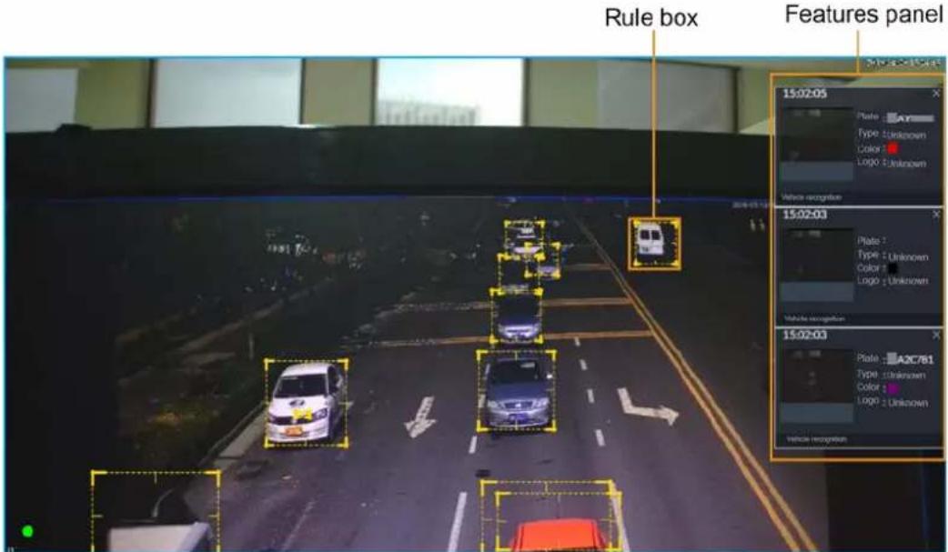
Point to the features panel, and the operation icons are displayed.
- Click ☑ to add license plate information to the plate database. For details, see "6.8.3.2.3 Adding from Detection Results".
- Click 📋 or double-click the vehicle image to play back the video image (10 s before and after the snapshot).
6.7.3.3 Detection Statistics
On the LIVE page, select a view and then click 📄. The VEHICLE TOTAL page is displayed.
Click 📋, and then select Vehicle Detection. The information of detected vehicles is displayed.
Figure 6-112 Vehicle detection
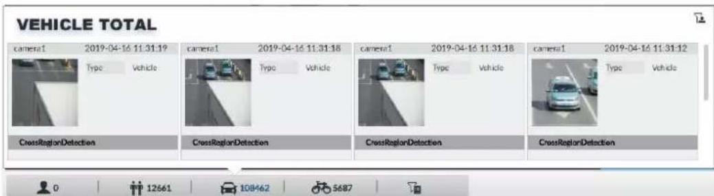
- Point to the information panel, and then click 📄 to add license plate information to plate database. For details, see "6.8.3.2.3 Adding from Detection Results".
- Point to the information panel, and then click 📋 or double-click the picture to play back the video image (10 s before and after the snapshot).
- Point to the information panel, and then click 🔒 to export the video and picture to specified saving path.

Make sure that USB storage device is connected during local operation.
6.7.4 Searching for Detection Information
Set event type and vehicle properties, and then search for vehicle detection information. For details, see "6.5.4.2 Vehicle Search".
6.8 ANPR
The system detects number plates using video metadata or vehicle recognition, and then compares the detected number plates with the ones in the database. When the system detects a match, an alarm is triggered.

Video metadata is only applicable to ANPR for low-speed vehicles at daytime checkpoints. Do not use video metadata for ANPR at entrances and exits, high-speed checkpoints or night scenes.
6.8.1 Procedure
Figure 6-113 Configure ANPR

flowchart
graph LR
    A["Start"] --> B["Set vehicle detection"]
    B --> C["Create plate database"]
    C --> D["Add vehicle plate"]
    D --> E["Configure plate comparison"]
    E --> F["Live view/AI search"]
    F --> G["End"]
6.8.2 Setting Vehicle Detection
To use the ANPR function, make sure that the system detects vehicles using video metadata or vehicle recognition. For details on configuring video metadata, see "6.5 Video Metadata". For details on configuring vehicle recognition, see "6.7 Vehicle Recognition".
6.8.3 Configuring Vehicle Database
Set vehicle database, and then the Device can compare vehicle plates with information in the database.
6.8.3.1 Creating Vehicle Database
Create vehicle database, and then classify and manage the database. Database of safe trusted vehicle list and blocked vehicle list can be created.
Procedure
Step 1 On the LIVE page, click +, and then select FILE > Vehicle Management > Vehicle Database.
Step 2 Click Create Vehicle DB.
Step 3 Set Vehicle DB Name, and select Type of vehicle database.
Step 4 Click Register Vehicle or Save and close. For details, see "6.8.3.2 Registering Vehicle Information".
Figure 6-114 Register vehicle info
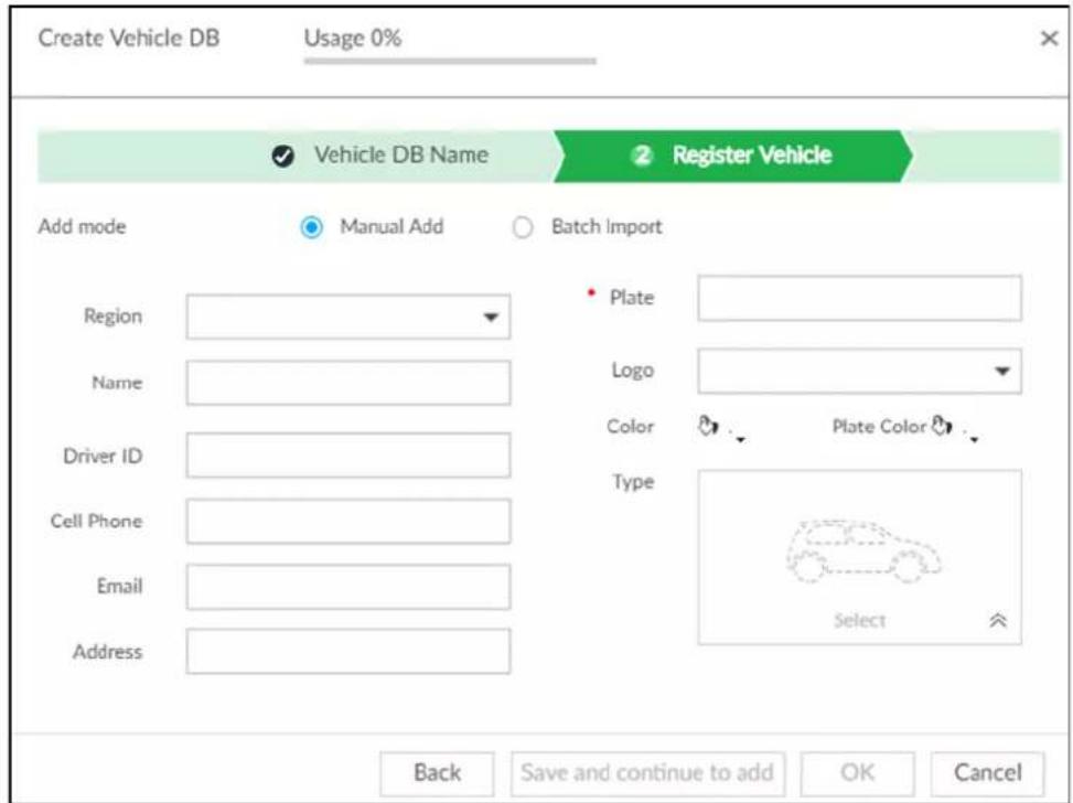
- Click Save and close to create database without editing its information.
The newly-created database can be viewed on the Vehicle Database page.
Related Operations
After creating a database, you can modify the database name, register plate information, arm the database, and delete the database.
Table 6-21 Related Operations
| View database information and status | : Database name.: Number of vehicle plates in the database.Allowlist/Blocklist: The database is in the allowlist or blocklist.: The database is not linked to channel for vehicle plate comparison. If armed, the linked device channel will be displayed. |
| Modify database name | Click next to the database name to modify its name. |
| Manage database | Double-click the database, and you can manage the vehicle plate information in the database. For details, see "6.8.3.3 Managing Vehicle Information". |
| Arm database | Link the database to camera channel for vehicle plate comparison. For details, see "6.8.4 Configuring Number Plate Comparison". |
| Delete database | Delete one by one: Point to the database, and click at the upper-right corner to delete it.Delete in batch: Point to a database, and check to select the database. Select multiple databases in this way, and then click Delete to delete the selected databases.Delete all: Select All, and then click Delete to delete all databases. |
6.8.3.2 Registering Vehicle Information
Add vehicle information to the created database. You can add vehicles one by one, in batches or directly add from the detection results.
6.8.3.2.1 Manual Add
Step 1 On the LIVE page, click + and then select FILE > Vehicle Management > Vehicle Database.
Step 2 Double-click the database.
Figure 6-115 Database
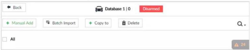
Step 3 Click Manual Add.
Figure 6-116 Vehicle register
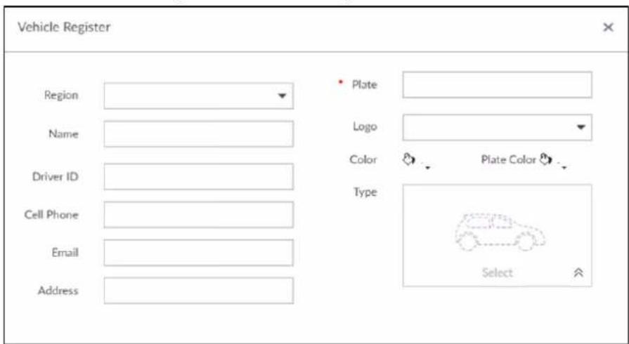
Step 4 Set the parameters.
Table 6-22 Vehicle register parameters
| Parameters | Description |
| Country or Region | The country or region that the vehicle belongs to. |
| Name Driver name. | |
| Driver ID Driver license number. | |
| Cell Phone Driver phone number. | |
| Email Driver email. | |
| Address Driver address. | |
| Plate Vehicle plate number. | |
| Logo Vehicle logo. | |
| Color | Click ↙, to select the color of vehicle. |
| Plate Color | Click ◊, to select the color of vehicle plate. |
| Type | Click , and you can select the vehicle type. Blue means already selected. |
Figure 6-117 Vehicle type
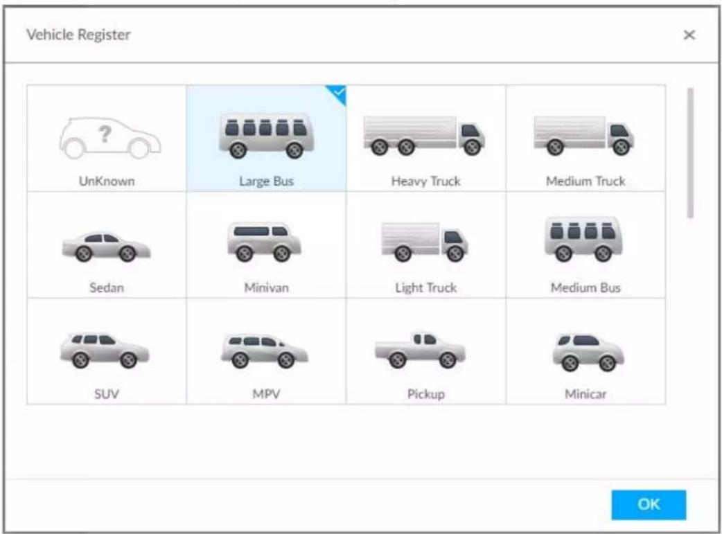
Step 5 Click Save and continue to add or OK.
- Click Save and continue to add: Save the current vehicle information, and then Continue to add next vehicle.
- Click OK: Save the current vehicle information.
6.8.3.2.2 Batch Import
Import vehicle information in batches.
Step 1 On the LIVE page, click +, and then select FILE > Vehicle Management > Vehicle Database.
Step 2 Double-click the database.
Step 3 Click Batch Import.
Figure 6-118 Batch import
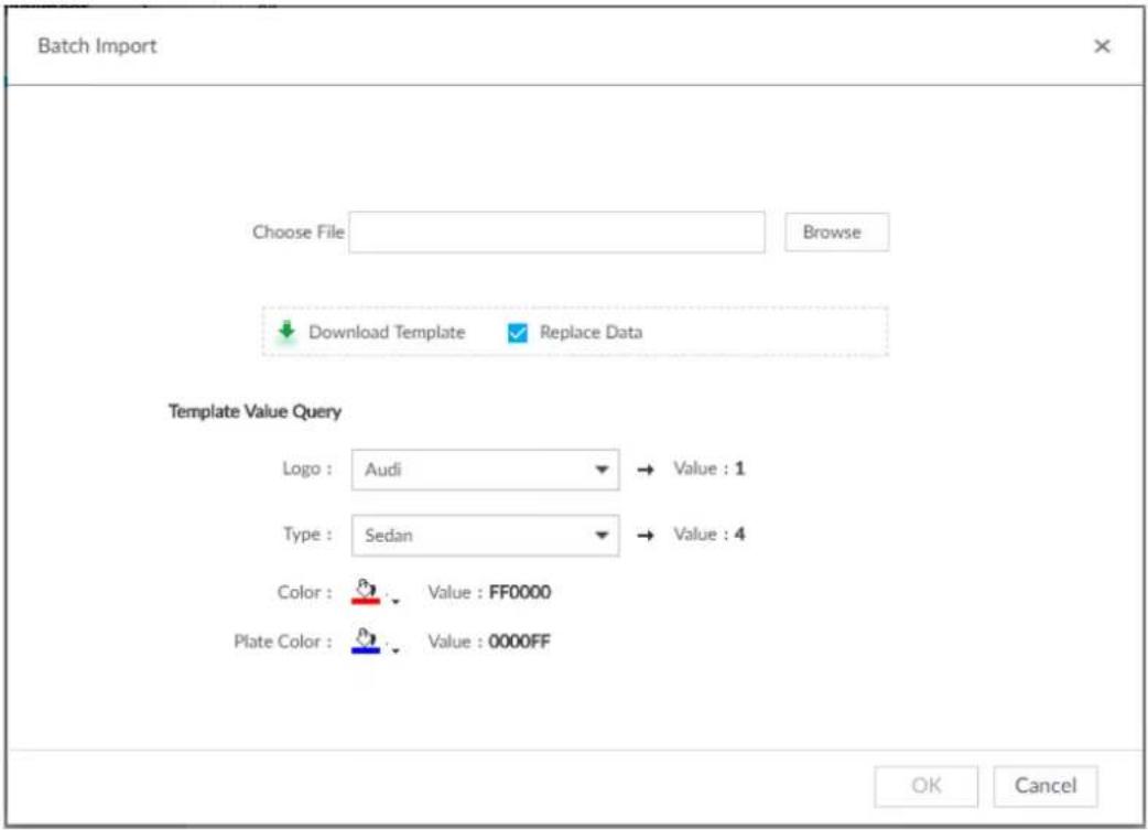
Step 4 Acquire and fill in the template file.
1) Click Download Template to download the template to local PC or USB storage device. The saving path might vary when operating on client or local interface.
- On client: Click ≡ on the upper right side, and then select ⏻ Download to view the saving path of template file.
- On local interface: Select the saving path of template file.
- On web interface: Template file is saved in the default download path of browser.
2) Fill in the template according to your actual needs.
Fill in the vehicle information according to the instructions. For logo, type, color, and plate color, fill in the corresponding code or value. Search the code or value on the Batch Import interface.
Step 5 On the Batch Import page, click Browse to import template file.
If the plate number in the template is the same as the number in the database, select
Replace Data to overlap the information in the database.
Step 6 Click OK.
Step 7 Click Add More or OK.
- Click Add More: Import vehicle information, and Continue to add vehicle information.
- Click OK: Import vehicle information.
The added vehicle information can be viewed on the Vehicle Database page.
Figure 6-119 Vehicle information
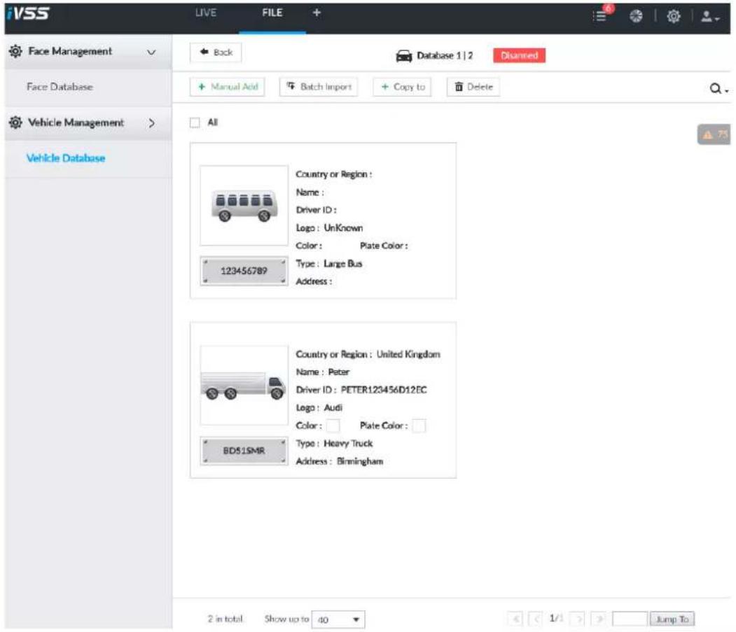
6.8.3.2.3 Adding from Detection Results
Add plate information from vehicle recognition or detection results to the database.
Step 1 On the LIVE page, select the vehicle information to be added.
- Click move the mouse pointer to the information panel, and then click
- On the Vehicle Recognition or Video Metadata page, move the mouse pointer to the vehicle recognition or vehicle detection panel, and then click 📄
The Vehicle Register page is displayed.
Step 2 Select a vehicle database from Vehicle DB, and enter the plate number atPlate. Other information can be filled in according to actual conditions.
Step 3 Click OK.
6.8.3.3 Managing Vehicle Information
After registering vehicle information, the information needs to be properly managed and maintained to keep it accurate and complete.
On the LIVE page, click +, and then select FILE > Vehicle Management > Vehicle Database. The database page is displayed.
On the page, the information can be edited, copied, or deleted.
6.8.3.3.1 Editing Vehicle Information
Step 1 Point to the database, and then click ☑.
Step 2 Modify vehicle information according to actual needs.
Step 3 Click OK.
6.8.3.3.2 Copying Vehicle Information
Copy the vehicle information in a database to another database. You can only copy and apply the vehicle information to a database of the same type. For example, vehicle information in a blocklist database can only be copied to another blocklist database.
Step 1 Point to the database, and then click □.

- Multiple vehicle information can be selected at a time.
- Select All to select information of all vehicles on the page.
Step 2 Click . + Copy to The Copy to page is displayed.
Figure 6-120 Copy to
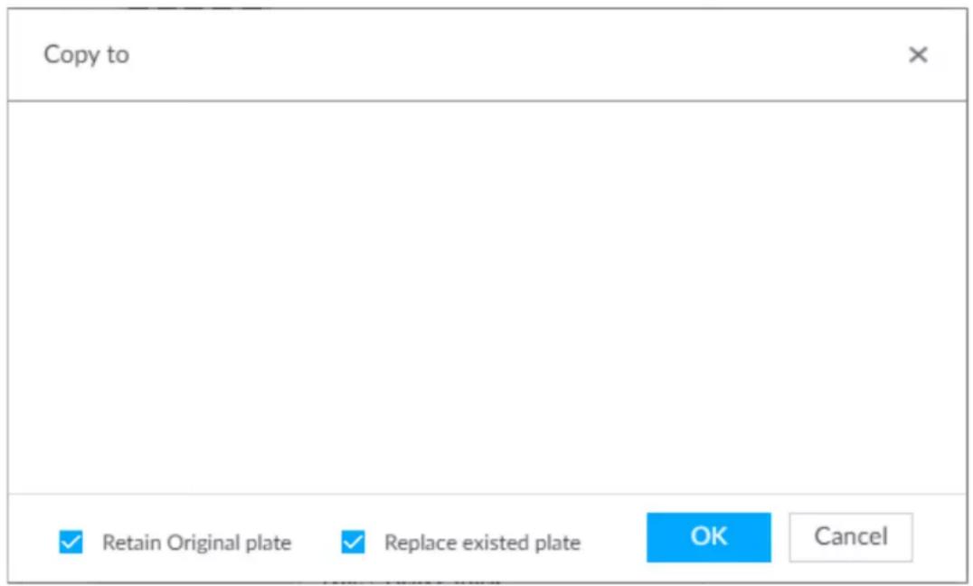
Step 3 Select the target database.

- Multiple databases can be selected at a time. Blue means already selected.
- Select Retain Original plate: When the same plate is detected, the vehicle information in the target database will not be replaced.
- Select Replace existed plate: When the same plate is detected, the vehicle information in the target database will be replaced.
Step 4 Click OK.
6.8.3.3.3 Deleting Vehicle Information
- Delete one by one: Point to the database, and then click ☑ at the upper right corner to delete the database.
- Delete in batch
Point to the database, and then click □ at the upper left corner to select the database. Select multiple databases in this way, and then click □ Delete to delete selected databases.
Select All, and then click Delete to delete all the databases on the page.
6.8.4 Configuring Number Plate Comparison
Set the alarm triggering rules after plate comparison.

The section uses AI by device for example, and might differ from the actual interface.
Step 1 Click 🎨 or + on the configuration page, and then select EVENT.
Step 2 Select device from the device tree on the left side.
Step 3 Select AI Application > Plate Comparison.
Figure 6-121 Plate comparison
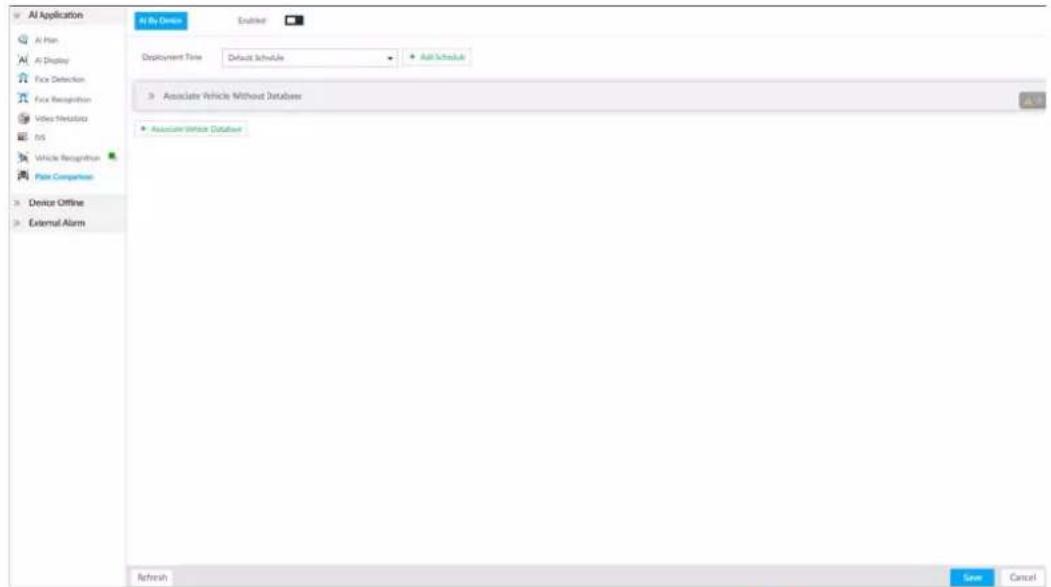
Step 4 Click □ to enable plate comparison. The icon changes to □.
Step 5 Click Deployment Time drop-down list to select schedule.
The Device links alarm event when an alarm is triggered within the schedule configured.
- Click Add Schedule to add new schedule if no schedule is added or the existing schedule does not meet requirements. For details, see "8.8.4 Schedule".
- Click View Schedule to view details of schedule.
Step 6 Link vehicle without database.
Enable linkage of vehicle without database. Alarm is triggered when vehicle not in the database is detected.
1) Click .»
Figure 6-122 Associate vehicle without database
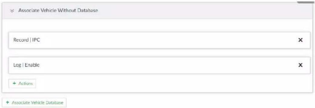
Step 7 Link database.

Repeat the following steps to link multiple databases.
1) Click Associate Vehicle Database, and select the database to be linked.
Figure 6-123 Database linkage
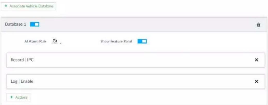
Table 6-23 Database linkage parameters
| Parameters | Description |
| AI Alarm Rule | Click 📄 to set the color of alarm rule box. |
| Show Feature Panel | Click 📄 and when alarm is triggered, the plate comparison information is displayed in the feature panel of video image. |
Step 8 Click Save.
6.8.5 Live View of ANPR
View vehicle comparison results on the LIVE page.
6.8.5.1 Setting AI Display
Set the display rules of detection results.

Make sure that view is created before setting AI display. To create view, see "7.1.1 View Management".
Step 1 Select a view from LIVE > View > View Group.
Step 2 Click ☐, and then select Vehicle tab.
Figure 6-124 Vehicle
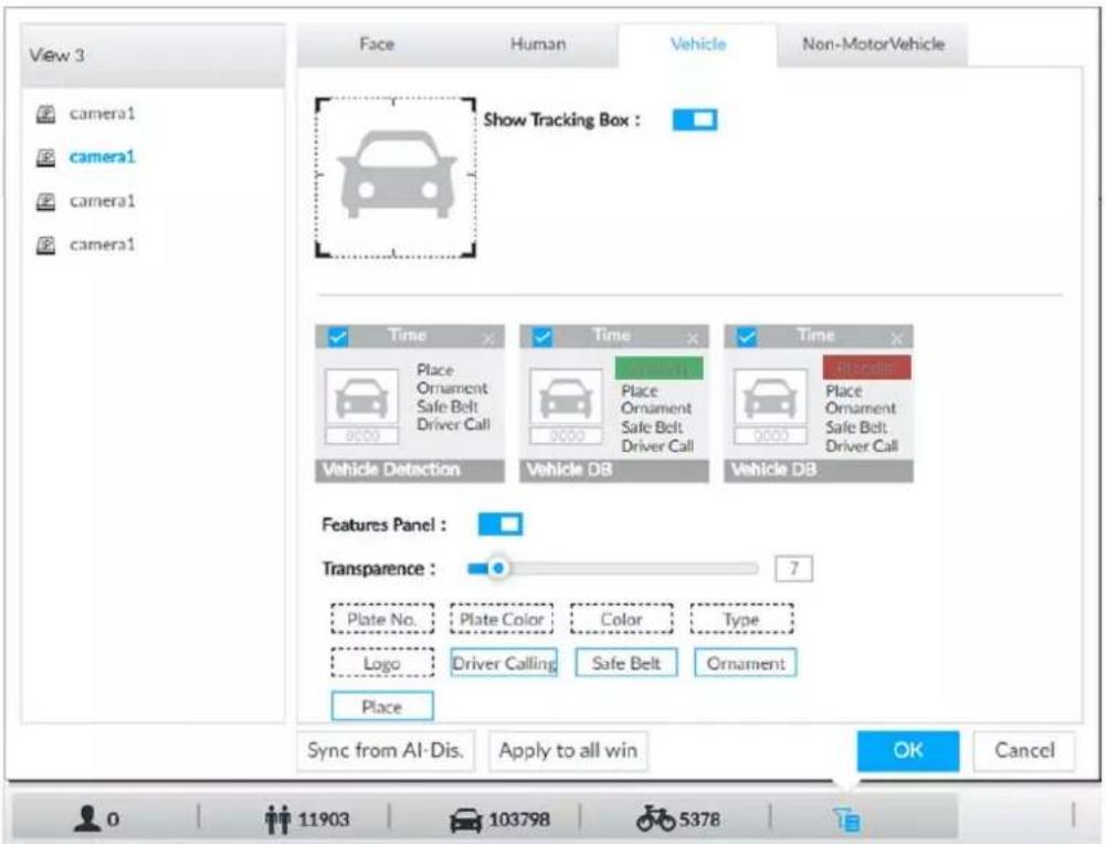
Step 3 Click □ next to Show Tracking Box to enable tracking box function.
A tracking box is displayed in the video image when target meeting detection rule is detected.
Step 4 Set features panel.
1) Click □ next to Features Panel to enable features panel function.
2) Features panel will be displayed at the right side of video image when target with selected features is detected.
3) Click □ to select the Vehicle DB panel. √ means the panel is selected.
4) (Optional) Drag ☐ to adjust the transparency of panel. The higher the value, the more transparent the panel.
5) (Optional) Select the features to be displayed in the panel.
- Up to 4 features can be displayed.
- 4 features are selected by default. To select another feature, click the selected feature to cancel it, and then click the feature to be displayed.
Step 5 Click OK.
6.8.5.2 Live View
On the LIVE page, select a view, and the video image of the view is displayed.
- Tracking box is displayed in the video image.
- Features panel is displayed at the right side of the video image.
Figure 6-125 Live
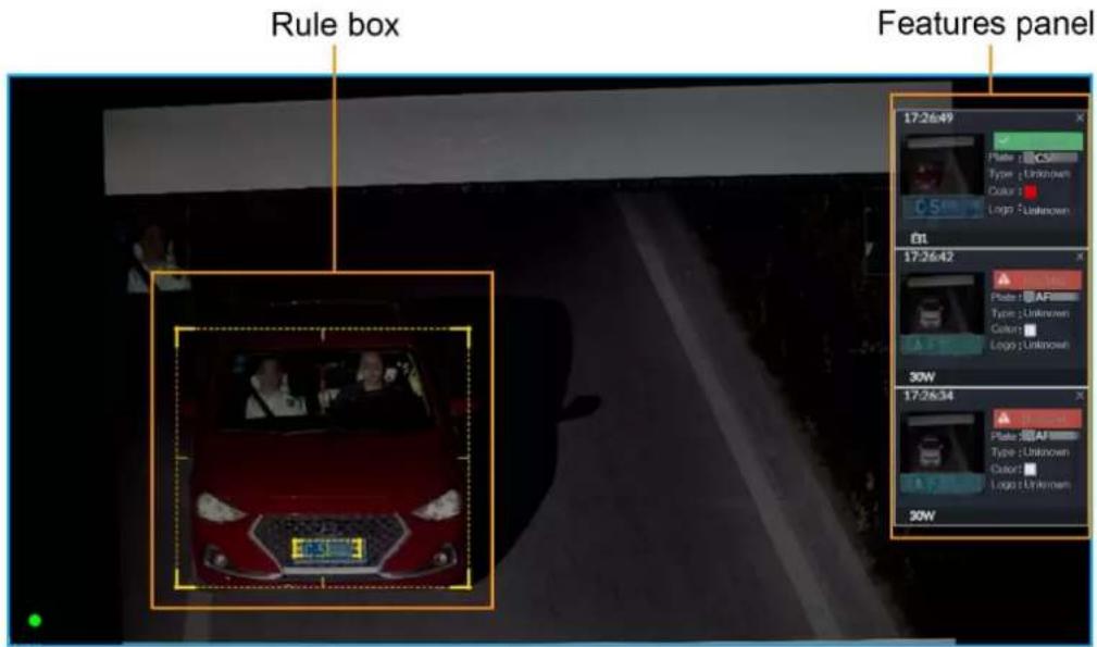
Point to the features panel, and the operation icons are displayed.
Figure 6-126 Icons
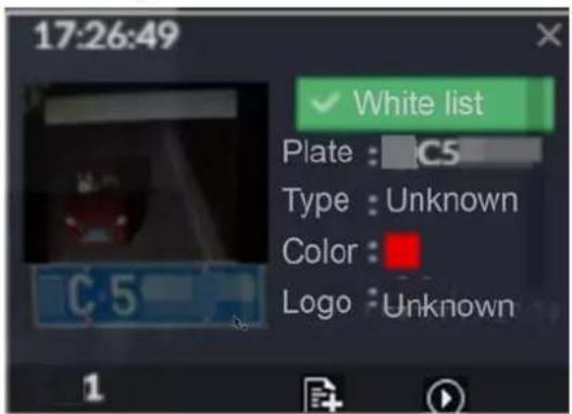
- Click ☐ to add license plate information to the plate database. For details, see "6.8.3.2.3 Adding from Detection Results".
- Click 📋 or double-click the vehicle image to play back the video image (10 s before and after the snapshot).
6.8.5.3 Detection Statistics
On the LIVE page, select a view and then click 📄. The VEHICLE TOTAL page is displayed.
Click ,and then select Vehicle Comparison (Blocklist) and Vehicle Comparison (Allowist). The vehicle comparison result is displayed.
Figure 6-127 Vehicle comparison
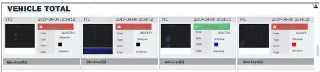
- Point to the information panel, and then click 📋 to add license plate information to plate
database. For details, see "6.8.3.2.3 Adding from Detection Results".
- Point to the information panel, and then click 📋 or double-click the picture to play back the video image (10 s before and after the snapshot).
- Point to the information panel, and then click 🔒 to export the video and picture to specified saving path.

Make sure that USB storage device is connected during local operation.
6.8.6 AI Search
Set search conditions such as device and properties, and then search information that meets the conditions. The Device supports searching by property and searching by database.
6.8.6.1 Searching by Property
Set search conditions such as device and properties, and then search vehicle recognition information that meets the conditions.
Step 1 On the LIVE page, click +, and then select AI SEARCH > Search by Vehicle.
Step 2 Select device, and then click Property tab.
Figure 6-128 Search by property
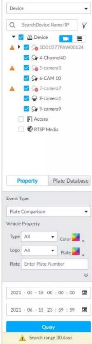
Step 3 Select Plate Comparison as the Event Type.
Step 4 Set vehicle properties and time period.
Step 5 Click or to set the color. means more than one color.
Step 6 Click Query.
The search result is displayed.
If license plate is detected, both the scenario and the license plate will be displayed.
Figure 6-129 Search result
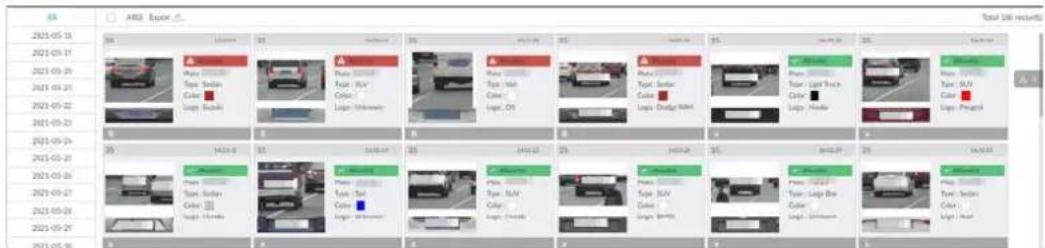
Click one displayed panel, and the icons are displayed.
Figure 6-130 Icons
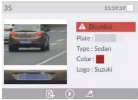
Table 6-24 Operations
| Icon | Operation |
| Select one by one: Point to the panel, and then click at the upper right side to select the panel.means the panel is selected.Select in batches: Select All to select all the panels on the page. | |
| Point to the panel, and then click or double-click the panel to play back the video record (10 s before and after the snapshot). | |
| Point to the panel, and then click to add picture to database. See "6.8.3.2.3 Adding from Detection Results". | |
| Export one by one: Click to export picture, video and video player. For details, see "6.2.4.3 Exporting Face Records".Export in batches: Select the panel and click to export picture, video or excel. For details, see "6.2.4.3 Exporting Face Records".After setting alarm linkage snapshot, during exporting images, the system exports detected images and panoramic images at the time of snapshot. |
6.8.6.2 Searching by Database
Search vehicle recognition information according to database.
Step 1 On the LIVE page, click +, and then select AISEARCH > Search by Vehicle.
Step 2 Select device from the device tree, and then click Plate Database tab.
Figure 6-131 Search by vehicle database
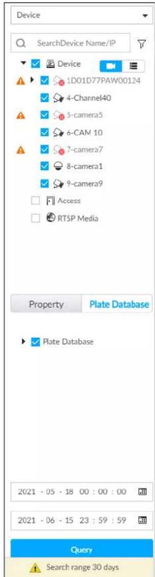
Step 3 Select the database to be searched.
Step 4 Click Query.
Step 5 The search result is displayed. If license plate is detected, both the scenario and the license plate will be displayed.
Click one displayed panel, and the icons are displayed. For operations of icons, see "6.8.6.1 Searching by Property".
6.9 Crowd Distribution Map
View and monitor people crowd to avoid crowd incidents, for example, stampede.

This function is only available with AI by camera.
6.9.1 Enabling AI Plan
Enable the corresponding AI plan before using AI by camera functions. For details, see "6.2.1 Enabling AI Plan".
6.9.2 Configuring Crowd Distribution Map
Set crowd distribution alarm rules.
6.9.2.1 Global Configuration
Draw lines on the image to determine the geographical scale of the image.
Step 1 Click 🎨 or click + on the configuration page, and then select EVENT.
Step 2 In the device tree, select a camera.
Step 3 Select AI Application > Crowd Distribution Map > Global Config.
Figure 6-132 Global config
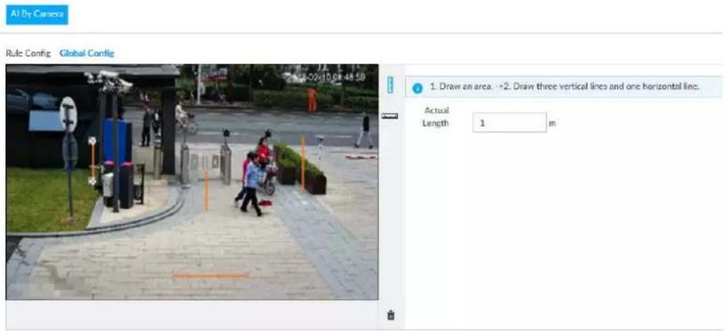
Step 4 Draw lines. Draw one horizontal line and three vertical lines.
- Click [] , draw vertical lines, and then enter their geographical distance values.
- Click , draw a horizontal line, and then enter the geographical distance value.
Step 5 Click Save.
6.9.2.2 Rule Configuration
Configure the alarm threshold for crowd monitoring. For example, when the crowd density reaches 8, an alarm is triggered.
Step 1 Click 🎨 or click + on the configuration page, and then select EVENT.
Step 2 In the device tree, select a camera.
Step 3 Select AI Application > Crowd Distribution Map > Rule Config.
Step 4 Click □ next to Enabled to enable rule configuration.
Step 5 Set detection rules.
- Set regional detection rules.
1) Click Add Rule.
Figure 6-133 Add Rules
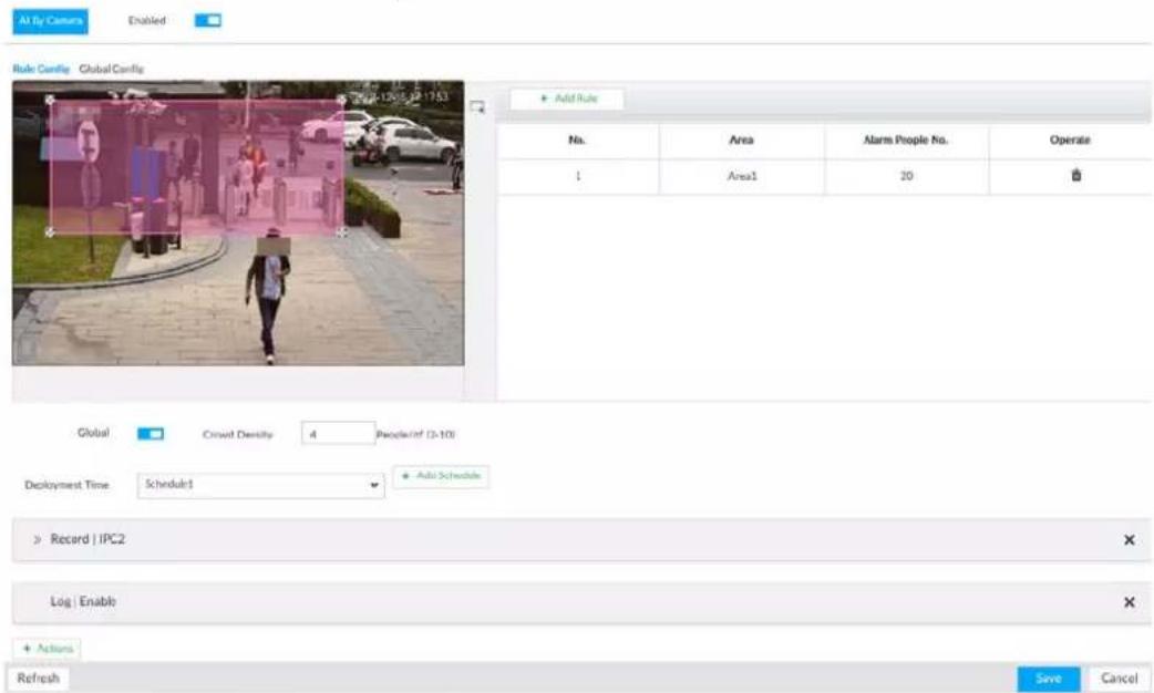
2) Drag ✗ to adjust the size.
3) Configure alarm threshold. Alarm is triggered when the detected people number reaches the threshold.
- Set global alarm.
1) Click ☐, and then drag ✗ to adjust the size of the yellow area.
2) Click □ to enable global detection.
3) Set crowd density. Alarm is triggered when the detected crowd density reaches the threshold.
Step 6 Select a schedule from the Deployment Time drop-down list.
The alarm linkage action is triggered only during the scheduled period.

To modify the schedule, click Add Schedule.
Step 7 Click Actions, and then select an action to be associated to the alarm.
Step 8 Click Save.
6.9.3 Live View of Crowd Distribution
On the LIVE page, open a view that contains the crowd distribution detection camera.
The video shows people numbers and distribution status in the detection areas in real time. The area frame flashes red when there is an alarm in the area.
Figure 6-134 Live view of crowd distribution
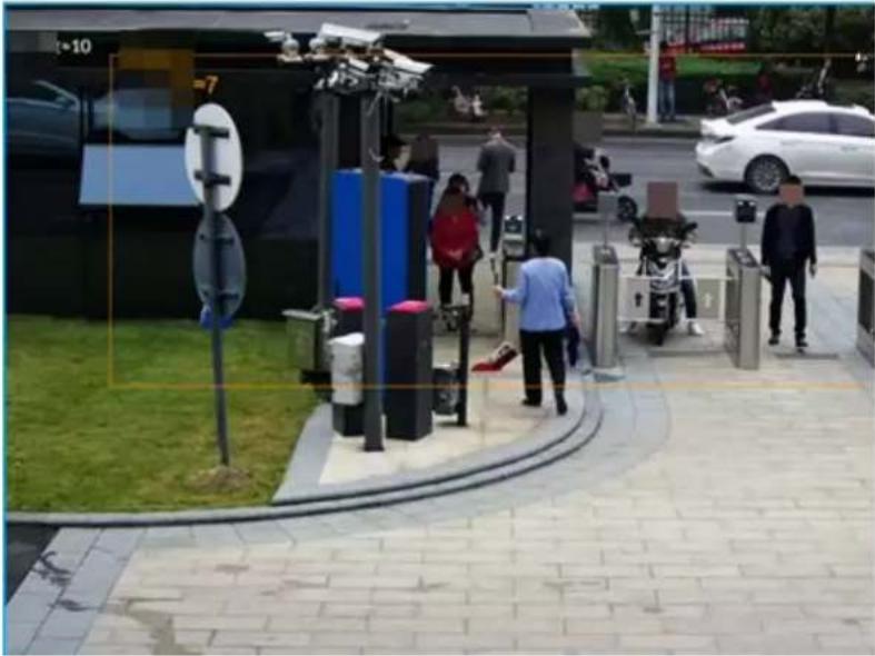
natural_image
Street scene with pedestrians near a modern public space featuring outdoor fitness equipment and a bus stop (no visible text or symbols)- Right-click on the live video, and then select Crowd Distribution Map > PIP. A blue section is displayed, and it shows the crowd distribution status inside the current view.
- Right-click on the live video, and then select Crowd Distribution Map > Global to switch to the distribution view. The view indicates crowd density and people heads in different colors.
6.10 Call Alarm
An alarm is triggered when the system detects a person calling. To configure call alarm, set call detection rules for the visible light channel of a thermal camera.

Call alarm is only available with AI by Camera.
6.10.1 Enabling AI Plan
Enable the corresponding AI plan before using AI by camera functions. For details, see "6.2.1 Enabling AI Plan".
6.10.2 Configuring Call Alarm
Configure call alarm rules.

The call alarm is only available with thermal cameras.
Step 1 Click 🎨 or click + on the configuration page, and then select EVENT.
Step 2 In the device tree, select the visible light channel of a thermal camera.
Step 3 Select AI Application > Call Alarm.
Step 4 Click □ next to Enabled to enable rule configuration.
Figure 6-135 Configure call alarm
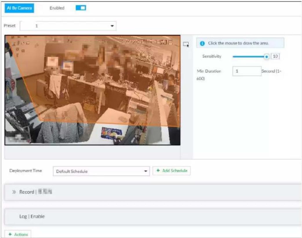
Step 5 Click and drag ✗ to adjust the size of the detection area (yellow area).
Step 6 Set Sensitivity and Min Duration.
- Sensitivity: The higher the Sensitivity is, the easier the call action is detected.
- Min Duration: The minimum duration the call action lasts. If the call action still lasts after the Min Duration, the system will trigger an alarm.
Step 7 Click Deployment Time to select a schedule from the drop-down list.
System triggers corresponding alarm actions only during the alarm deployment period.

You can select an existing schedule from the Deployment Time drop-down list. You can also add a new schedule. For details, see "8.8.4 Schedule".
Step 8 Click Action to set alarm action. See "8.4.1 Alarm Actions" for detailed information.
6.10.3 Live View of Call Alarm
Log in to PCAPP. On the LIVE page, open a view that contains the call alarm detection channel. The call action is highlighted in red when the alarm is triggered.
Figure 6-136 Live view of call alarm
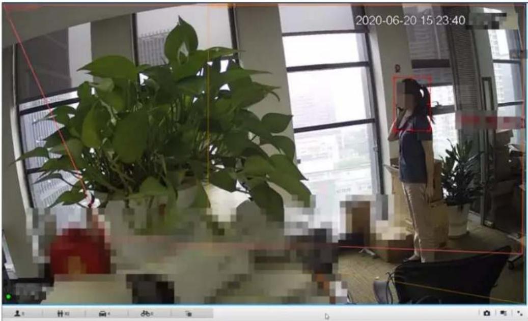
6.10.4 Call Alarm Search
Search for videos or images of call alarm.
Step 1 On the LIVE page, click +, and then click Search.
Figure 6-137 Search
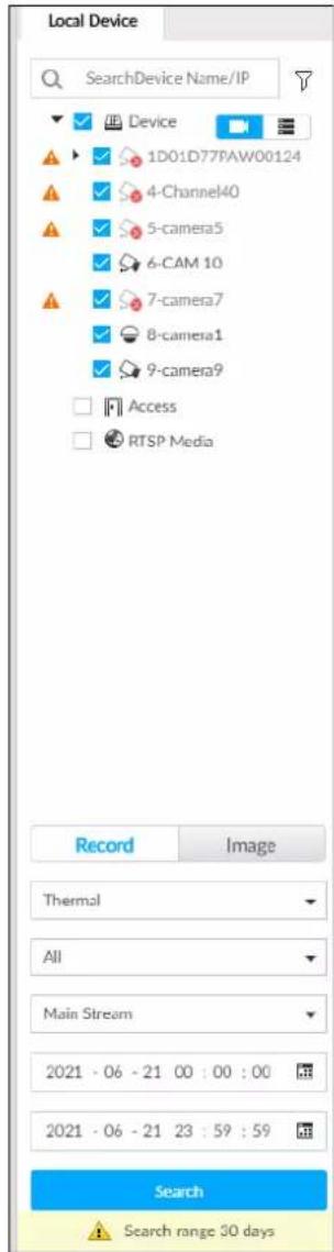
Step 2 Select one or more devices.
Step 3 Set search parameters.
- Record
1) Select Thermal as record type.
2) Select Call Detection as detection type.
3) Select a stream type.
4) Set time period. - Image
1) Select Thermal as record type.
2) Select Call Detection as detection type.
3) Set time period.
Step 4 Click Search.
6.11 Smoking Alarm
An alarm is triggered when the system detects a person smoking. To configure smoking alarm, set
smoking detection rules for the visible light channel of a thermal camera.

Smoking alarm is only available with AI by Camera.
6.11.1 Enabling AI Plan
Enable the corresponding AI plan before using AI by camera functions. For details, see "6.2.1 Enabling AI Plan".
6.11.2 Configuring Smoking Alarm
Configure smoking alarm rules.
Step 1 Click 🎨 or click + on the configuration page, and then select EVENT.
Step 2 In the device tree, select the thermal channel of a thermal camera.
Step 3 Select AI Application > Smoking Alarm.
Step 4 Click □ next to Enabled to enable rule configuration.
Figure 6-138 Configure smoking alarm
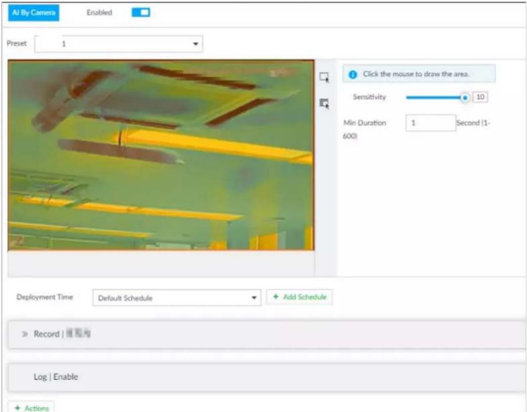
Step 5 Set Sensitivity and Min Duration.
- Sensitivity: The higher the Sensitivity is, the easier the call action is detected.
- Min Duration: The minimum duration the call action lasts. If the call action still lasts after the Min Duration, the system will trigger an alarm.
Step 6 Click Deployment Time to select a schedule from the drop-down list.
System triggers corresponding alarm actions only during the alarm deployment period.

You can select an existing schedule from the Deployment Time drop-down list. You can also add a new schedule. For details, see "8.8.4 Schedule".
Step 7 Click Action to set alarm action. See "8.4.1 Alarm Actions" for detailed information.
Step 8 Click Save.
6.11.3 Live View of Smoking Alarm
Log in to PCAPP. On the LIVE page, open a view that contains the smoking alarm detection channel. The smoking action is highlighted in red when the alarm is triggered.
7 General Operations
This chapter introduces general operations such as live view, playback, alarm, AI functions, and IVS.
7.1 Live and Monitor
After you have logged in, the LIVE page is displayed.

Point to the middle of video window and the left column. | is displayed. Click the icon if you need to hide the left column.
Figure 7-1 Live (1)
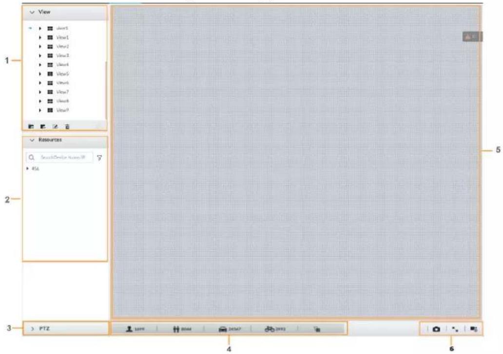
Figure 7-2 Live (2)
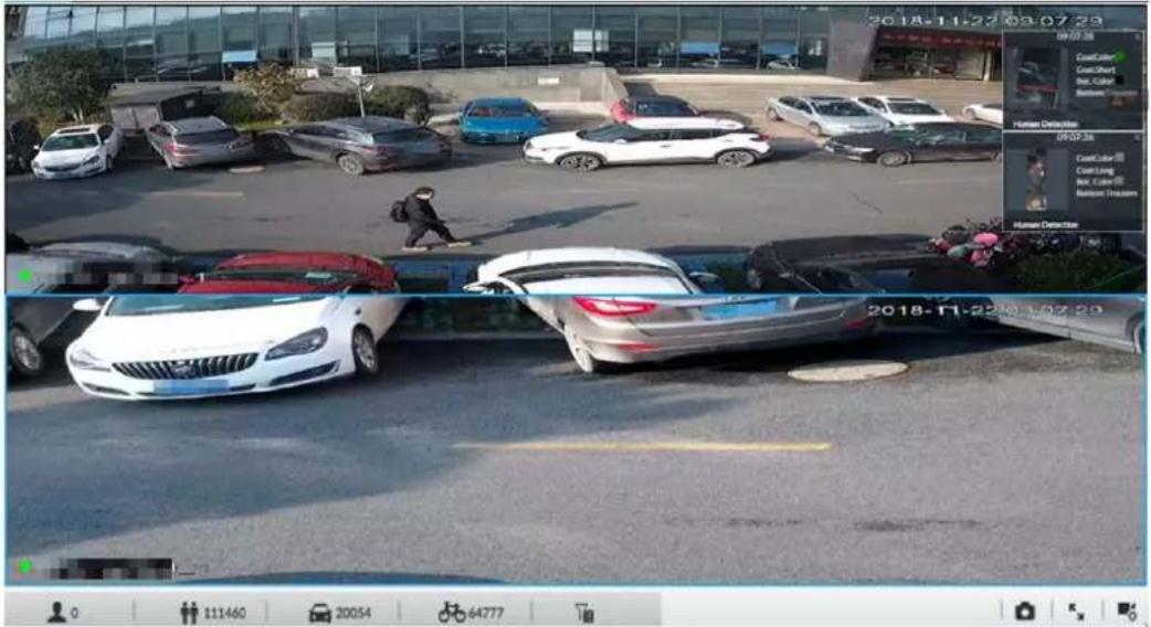
Table 7-1 Live page description
| No. | Description |
| 1 | View zone. Displays the created view and view group. See "7.1.1 View Management" for detailed information. |
| 2 Resource pool. | Displays the added remote device list. |
| 3 | PTZ zone. It is to control the PTZ. See "7.1.3 PTZ" for detailed information. |
| 4 | Smart preview icons. View face statistics, person statistics, IVS statistics and AI display. |
| 5 | Video play window. See "7.1.1.2 View" window for detailed information. |
| 6 | Click take snapshot.Click for full-screen view.Click go to the VIDEO RECORDING page for recording configuration. |
7.1.1 View Management
View is composed of video images of several remote devices. Go to the view panel at the top left corner of the LIVE page to view or call the view.
- System has created views group by default. Create view or view group under the View.
- Double-click the view or drag the view to the play panel on the right side. Device begins playing the real-time video from the remote device.
- Click □ to select views and its sub-node.
Figure 7-3 View
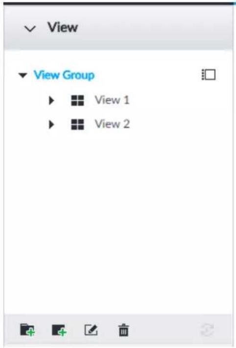
7.1.1.1 View Group
View group is a group of views. The view group allows you to categorize and manage view. It is easy for you to search and find the view. Create view or view group under the View.

- Device supports maximum 100 view groups.
- The views hierarchy shall not be more than 2. For example, after you create View Group 1 under View, you can create a sub-level View Group 2 under View Group 1. However, you cannot create sub-level group under View Group 2.
7.1.1.1.1 Creating View Group
Step 1 Follow the steps listed below to create a view group.
- Click View Group or a created view group, and then click 📄.
- Right-click View Group or a created view group, and then select Add View Group.
System creates one view group.
Figure 7-4 Create view group
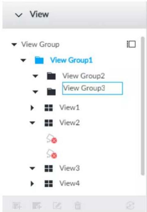
Step 2 Set view group name.
- The view group name ranges from 1 to 64 characters. It can contain English letters, numbers and special characters.
- View group is to classify or category different view groups. We recommend the view group name shall be easy to recognize.
Step 3 Click any black space on the page.
7.1.1.1.2 Operation
After creating view group, view group can be renamed or deleted.
Figure 7-5 Rename
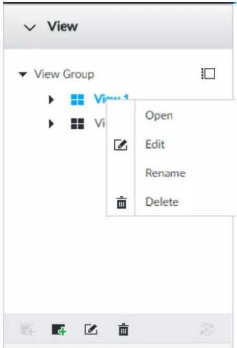
Table 7-2 View group
| Name | Operation |
| Rename view group | Select a view group and then click. Set view group name and click any spare panel.Right-click view group and select Rename. Set view group name and click any spare panel. |
| Delete View group | Please be advised that once you delete view group, all views under current view group will be deleted at the same time.Select view group and click .Right-click view group and then select Delete. |
7.1.1.2 View
View is a video component of several remote devices. You can drag several remote devices to the same view and when view function is enabled, you can view the real-time video from several remote devices at the same time.
7.1.1.2.1 Creating View
Create view is to add several associated remote devices to the same View. It is easy to view the real-time video from several remote devices at the same time.
Prerequisites
Remote device has been added. See "5.4.2 Adding Remote Device" for detailed information.
Procedure
Step 1 Follow the steps listed below to create view.
- Select a view group and then click, select Add view.
• Right-click a view group, select Add view.
Figure 7-6 Edit view (1)
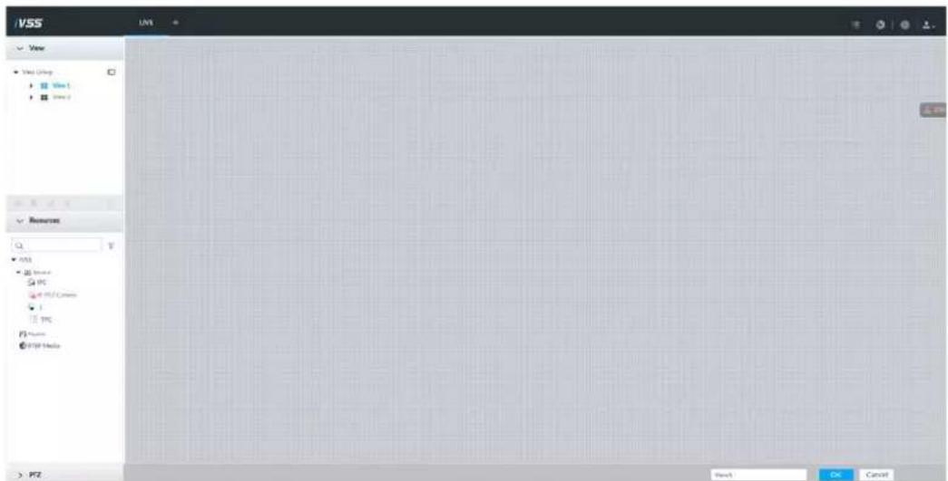
Step 2 Double-click a remote device in resource pool, or drag the remote device to the right panel.
After one remote device is added, layout grid is displayed.
- Each layout grid supports one remote device. If you want to add several remote devices, drag the rest remote device to other idle layout grid.
- If the layout grid has added the remote device, drag another remote device to current grid is to replace the original one.
- Point to the orange panel (such as 📄) of the view window, click the view window and then drag after you see the arrow icon. It is to adjust view window size.

- Device automatically creates the view grids amount according to the selected remote device amount. Device supports maximum 36 view windows.
- The view window fills in the whole layout grid by default. Right-click to select Original Scale > ON, and turn on the Original Scale. The device automatically adjusts view window size according to resolution of remote device.
- When adjusting view window position, drag the view window to the layout grid of the green background color. You cannot drag the view window to the grid of red background color.
Figure 7-7 Edit view (2)
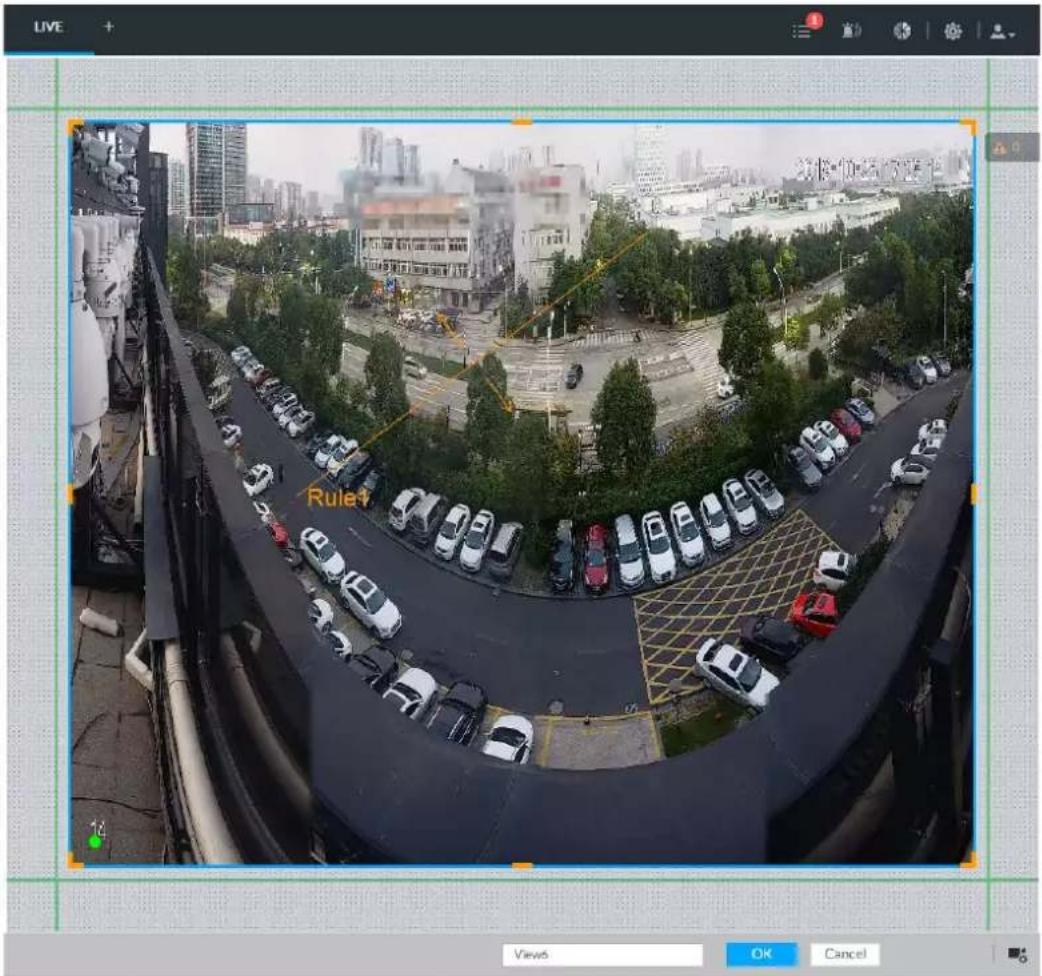
Step 3 Set view name.
The view name ranges from 1 to 64 characters. It can contain English letters, number and special character.
Step 4 Click OK to save the configuration.
Device pops up a prompt of Successfully operated.
Related Operations
After creating view, view can be edited, enabled, renamed or deleted.
Table 7-3 View
| Name | Operation |
| Edit View | Edit remote device in the view, window layout and view name. See "7.1.1.2.2 Editing View" for detailed information. |
| Enable view | After enabling view, view real-time image of remote device in the view. See "7.1.1.2.3 Enabling view" for detailed information. |
| Rename view | Select a view group and then click ☑. Set view group name and click any spare panel.Right-click view and select Rename. Set view name and click any spare panel. |
| Delete view | Delete: Select a view and then click ☑, or right-click view and then select Delete.Batch delete: Click ,select views you want to delete and then click .☐ |
Figure 7-8 Menu
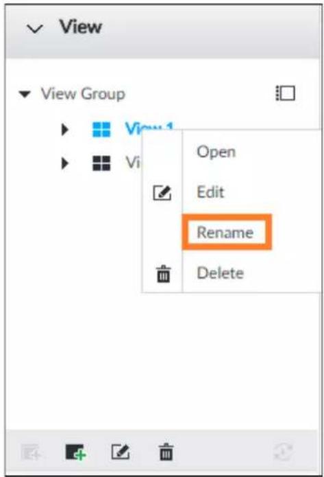
7.1.1.2.2 Editing View
In edit view mode, you can perform the following functions:
- Add, or delete the remote device on the view.
- Adjust the view grid display.
- Modify view name.
Step 1 Right-click a view and then select Edit.
Figure 7-9 Edit view
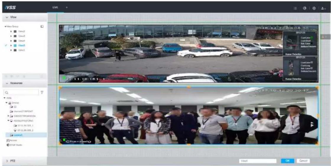
Step 2 Edit view as you require.
- Add remote device: Double-click remote device in the resource pool, or drag the remote device to the free layout grid on the right panel.
- Delete remote device: Point to window on the right, and click ✗ at the top right corner.
- Move window position: Select and hold on a view window, move it to the proper position and release mouse.
- Change window position: Select and hold on one view window and then drag to another view window.
- Change window size: Move your mouse to the orange panel on the window (such as ☐). Hold and drag the view window after you see the arrow icon.
- Modify view name: Set view name on . View1

When adjusting view window position, drag the view window to the layout grid of the green background color. You cannot drag the view window to the grid of red background color.
Step 3 Click OK to save the configuration.
7.1.1.2.3 Enabling view
Right-click the view and select Open, or double-click view to open the view window.
Figure 7-10 View window
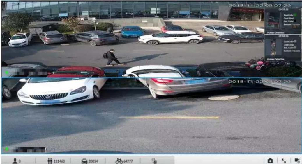
When enabling the view, you can change video position, zoom video window.

- When adjusting view window position, drag the view window to the layout grid of the green background color. You cannot drag the view window to the grid of red background color.
- Point to view window. Window task column is displayed to snapshot, enable record and turn off view window. See "7.1.1.3.1 Task Column" for detailed information.
- Right-click view window, you can switch bit streams, set digital zoom. See "7.1.1.3.2 Shortcut Menu" for detailed information.
Table 7-4 View function
| Name | Description |
| Exchange window position | Press one view window and drag it to another view window, it is to exchange these view window position. The exchanging window position operation is valid only once.Disable and then enable view again, the view window restores original position. If you want to change view window position permanently, go to the view edit mode to set. See "7.1.1.2.2 Editing View" for detailed information. The exchanging window position operation is valid only once.Disable and then enable view again, the view window restores original position. If you want to change view window position permanently, go to the view edit mode to set. See "7.1.1.2.2 Editing View" for detailed information. |
| Zoom in video window | Once current view window amount is too much (more than 9), click one view window, device displays current view window at the center of the window in the zoom in mode. Click any other blank position, you can view window restores original size.Double-click a view window, device displays view window at one window. Double-click view window again or click any blank position, the view window restores original size. |
| Add view window | In the resource pool, double-click the remote device or drag the remote device to the right panel, you can add remote device to current view.Drag the remote device to the view window to replace the original remote device.The modified view layout is valid only for once if you do not click OK button. Close and enable view again, the view layout restores original layout. |
| Close view window | Point to one view window, click × to close the view window.Close view window, device automatically adjusts view layout according to the rest remote device amount and play panel free space. |
7.1.1.3 View Window
Right-click the view, select Open, or double-click view to open the view window.
Figure 7-11 View window
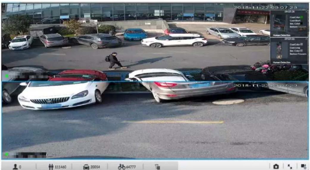
7.1.1.3.1 Task Column
Point to view window. The icons are displayed.
Figure 7-12 View window
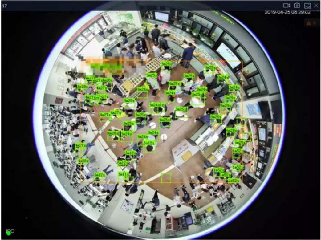
Table 7-5 Window task column
| Name | Description |
| Start Instant Video Recording | Clickto start recording manually. Now the icon becomesClickto stop recording.System stops recording according to the instant record length settings if you do not clickagain to stop.On different interfaces, recording storage path varies.LocalWhen USB storage device is connected, recordings are saved in USB storage device.Otherwise, the recordings are saved in the device. Query or export manual recording by playback control.PCAPPDefault storage path of recording is C:/Program Files (x86)/iVSS/video. Set storage path. |
| Snapshot | Click snapshot.At different interfaces, snapshot storage path varies.LocalWhen USB storage device is connected, snapshots are saved in USB storage device.Otherwise, the snapshots are saved in the device. Query or export the snapshots by playback control.PCAPPDefault storage path of snapshot is C:/Program Files (x86)/iVSS/pictures. Set storage path. |
| Search by image | Take snapshots of face or human during live view, and use the snapshot to search for similar targets. |
| Close view window | Click to close view window. |
7.1.1.3.2 Shortcut Menu
Right-click the view window. The shortcut menu is displayed.
Figure 7-13 Shortcut menu
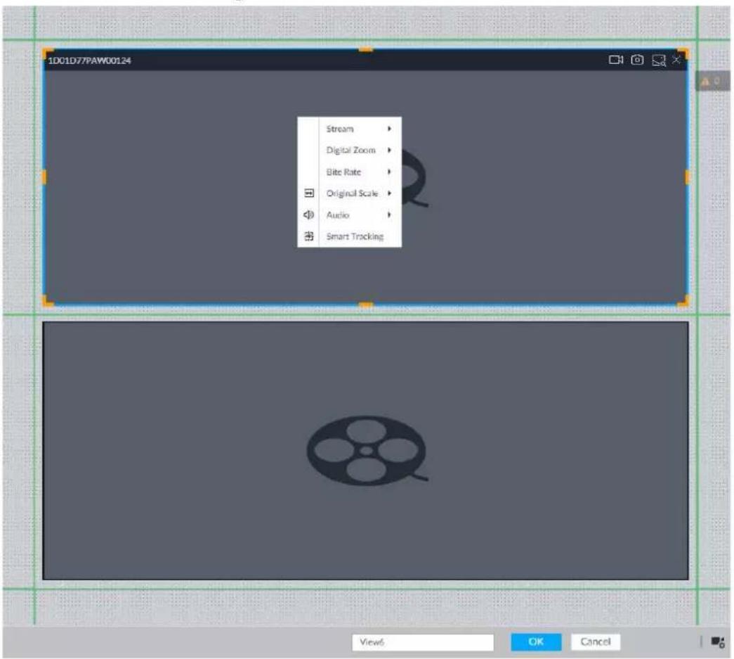
Table 7-6 Shortcut menu
| Parameters | Description |
| Stream | Set current window stream. It includes main stream/sub stream 1/sub stream 2. |
| Digital Zoom | Set digital zoom. Zoom in one part of live image to view details. |
| Bit Rate | Displays real-time bit rate on the window or not. |
| Original Scale | Set video window scale.ON: System automatically adjusts video window scale according to the resolution.OFF: System automatically adjusts video window scale according to the remote device amount and the free space on the playback panel. |
| Audio | Set audio output. It includes audio 1, audio 2, mixing and off. |
| Fisheye Dewarp | Set installation methods and display modes of fisheye cameras.[8068]This function is only available on fisheye camera. |
| Smart Tracking | Intelligently track targets.This function is only available on the multi-sensor panoramic camera + PTZ camera. |
Figure 7-14 View window
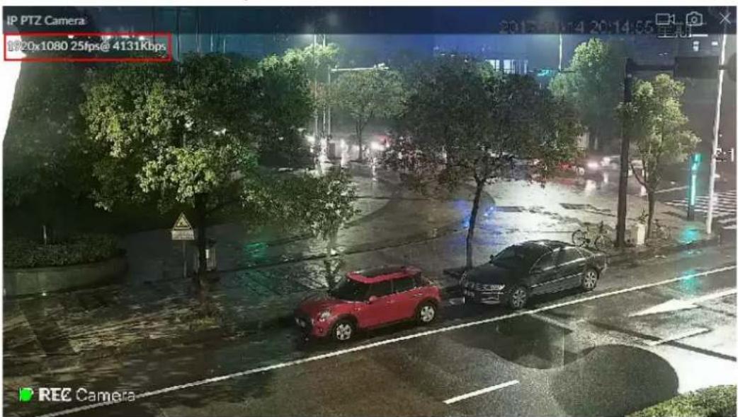
7.1.1.3.3 Digital Zoom
The digital zoom function allows you to zoom in a specified zone to view the video details.
After enabling view, right-click Digital Zoom > ON. Select a zone in view window, and the selected zone will be zoomed in.
- In zoom in status, press any position on the video window and then drag, you can view the zoom in effect of other zones.
- Select a zone you want to zoom in on the video window again, system zooms in the zone at the larger rate.
- Right-click and then select Digital Zoom > OFF, it is to cancel zoom in effect. The video restores original effect.
Figure 7-15 Digital zoom
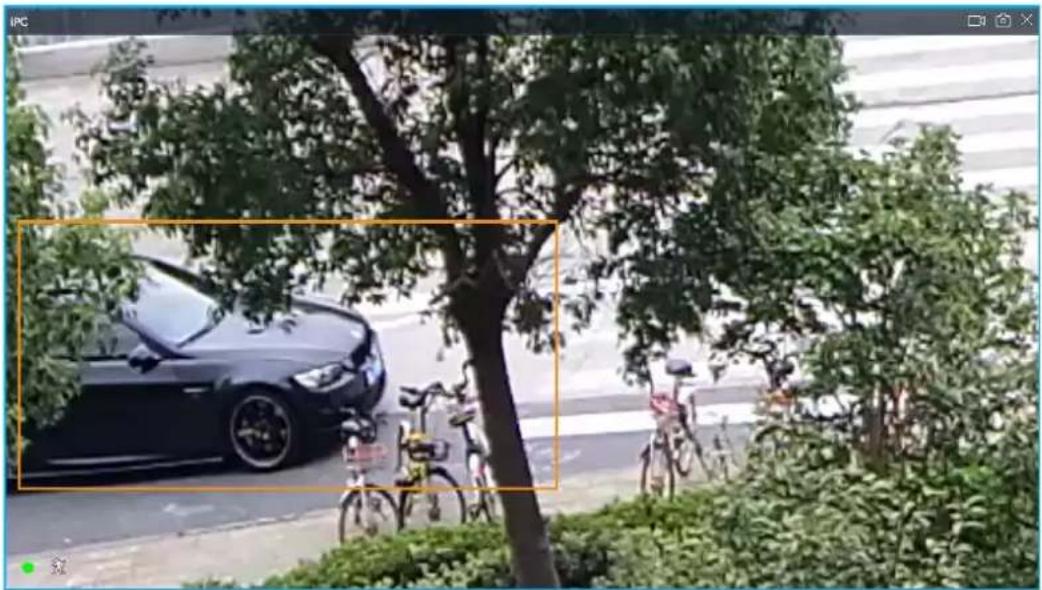
natural_image
Street scene with a black car parked under trees, bicycles, and greenery in the foreground (no visible text or symbols)7.1.1.3.4 Searching by Image
Draw a frame on the video to select an image than contains targets, and then use the images to search for similar faces or human bodies.
Step 1 Click at the upper-right corner of the video.
Step 2 Draw a frame on the video to select an image than contains target faces or humans.
- Point to the frame, and then you can move its position.
- Drag to adjust the size.
Step 3 Click Search by Picture.
You are prompted to select a type of target.
Step 4 Select a target type.
Step 5 Click OK. The system starts searching all the cameras for records within a week.
7.1.1.3.5 Fisheye Dewarp
Set the installation method and display mode of fisheye cameras.

This function is available on select models.
• Installation method: Select the installation method according to the actual situation.
- Display mode: Select the display mode of live view.
Figure 7-16 Fisheye dewarp
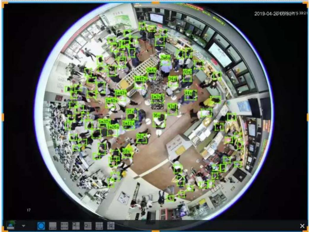
Step 1 Right-click on the live video, and then select Fisheye Dewarp.
Step 2 Select an installation method.
- Click to select ceiling mount.
- Click to select wall mount.
- Click to select ground mount.
Step 3 Select a display mode.
Table 7-7 Display mode
| Installation Method | Display Mode | Description |
| Ceiling/wall/ground mount | The original fisheye image. | |
| Ceiling/ ground mount | 360° panoramic image + section images. | |
| 2 corrected 180° images, which consist the 360° panoramic image. | ||
| 1+3 Original image + 3 section images. | ||
| 1+4 Original image + 4 section images. | ||
| Corrected 360° panoramic image + section images. | ||
| 1+8 Original image + 8 section images. | ||
| Wall mount | Corrected 180° image from left to right. | |
| Corrected 180° image + 3 section images. | ||
| Corrected 180° image + 4 section images. | ||
| Corrected 180° image + 8 section images. |
Step 4 Click OK.
7.1.1.3.6 Smart Tracking
Track targets manually or automatically. This function is only available on the multi-sensor panoramic camera + PTZ camera.

Make sure that the linked tracking function has been enabled.
Step 1 Right-click on the live video, and then select Smart Tracking > ON.
Figure 7-17 Smart tracking
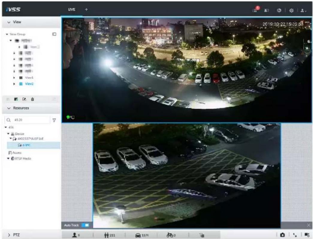
Step 2 Select the tracking method.
- Manual positioning: Click a spot or select a zone on the bullet camera video, and then the PTZ camera will automatically rotates there and zoom in.
- Manual tracking: Click or select a target on the bullet camera video, and then the PTZ camera automatically rotates and tracks it.
- Automatic tracking: The tracking action is automatically triggered by alarms in according to the pre-defined rules.
7.1.1.3.7 Thermal
On the LIVE page, a thermal camera has 2 channels: Visible light channel and thermal channel. Select the thermal channel, point to any position on the live video, and then you can view the real-time temperature of the position.
Figure 7-18 Thermal
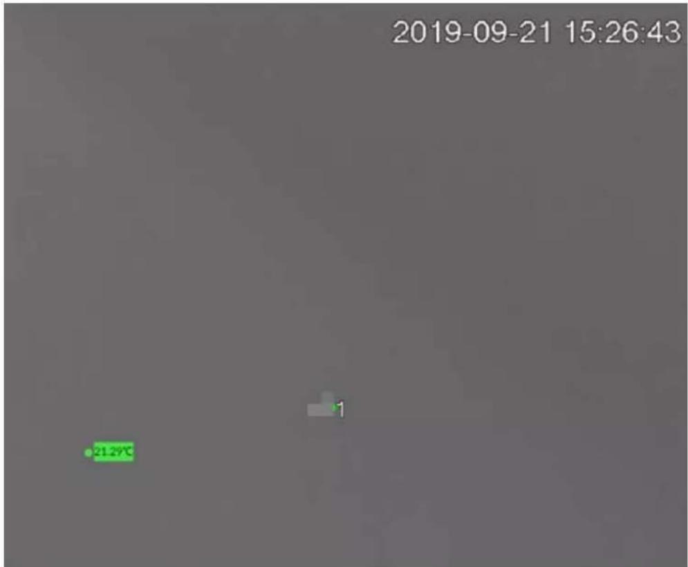
7.1.1.3.8 Talk
The Talk function enables voice interaction between the Device and remote devices, improving the efficiency in handling emergency events.
Step 1 Log in to PCAPP.
Step 2 Open a view on the Live page.
Figure 7-19 Talk
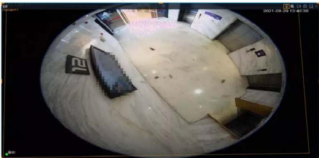
natural_image
Interior view of a modern building with large windows and minimal furniture, captured in a fisheye lens (no visible text or symbols)Step 3 Click ☐ at the upper-right corner of the view window to enable the Talk function. Click again to disable the function.
7.1.2 Resources Pool
The resource pool displays the added remote device list. The system automatically divides into groups according to device type.
Figure 7-20 Resources pool
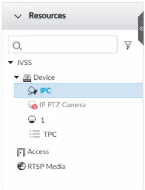
Table 7-8 Resources pool description
| Operation | Description |
| Search device | Input key words at, device displays the corresponding remote devices.Support fuzzy search. |
| Filter device | Click and then select all, online, offline. It is to filter the disqualified remote device. |
| View device status | Display remote device status on the resources pool.If the remote device name and icon is black, it means the remote device is online. For example, IPPTZ CameraIf the remote device name and icon is gray, it means the remote device is offline. For example, IPCIf there is an icon before the remote device, it means remote device is abnormal, alarming, and so on. Point to view the detailed information. |
| Mouse Operations | Point to the remote device name, you can view remote device IP address and port number.On the device list, click one remote device and then press Ctrl, click other remote device, you can select several remote devices at the same time.On the device list, select one remote device and then press Shift, click other remote device, select current two remote devices and all remote devices listed between them.Right-click a remote device to connect to disconnect it.Double-click remote device or drag the remote device to the view window on the right panel, you can enter edit the view interface. See "7.1.1.2.2 Editing View" for detailed information. |
7.1.3 PTZ
Set PTZ functions and perform PTZ control so the PTZ camera can rotate accordingly to monitor all directions.

The PTZ functions might vary depending on the device models.
Log in to PCAPP. On the LIVE page, PTZ is displayed at the lower-left corner.

The following figure for reference only. The grey button means current function is null.
Figure 7-21 PTZ
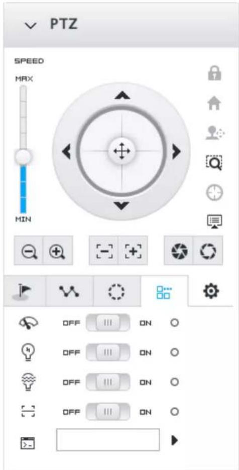
Table 7-9 PTZ Icons
| Icons | Description | |
 | Press and hold on , and drag it up and down. It is to set PTZ speed. The higher the value is, the faster the PTZ speed is. | |
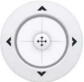 | Control PTZ movement in the following ways.Press and hold on to control PTZtop/bottom/left/right/top left/top right/lower-left/lower-right direction.Click the arrows to control PTZ direction. | |
| Click to enable 3D positioning function. | ||
| Click to enable auto focus, and then the camera image becomes focused automatically. | ||
| Click to enter the PTZ menu mode. For details, see "7.1.3.1 PTZ Menu Settings". | ||
 | Zoom. Click to adjust lens zoom rate of the remote device. | |
 | Focus. Click to adjust lens focus of the remote device. | |
 | Iris. Click it to adjust iris size of the remote device. | |
| Click to use windshield wiper, light, IR and linear scan, auxiliary commands.: Drag the on/off slider to the left or right to enable or disable windshield wiper.: Drag the on/off slider to the left or right to enable or disable the light.: Drag the on/off slider to the left or right to enable or disable the IR.: Drag the on/off slider to the left or right to enable or disable linear scan.: Set the No. of auxiliary functions. Click to enable the corresponding auxiliary function. | ||
| Click to enter PTZ calling page.Go to the remote device to set corresponding PTZ function before you call it.Click to enter the preset page.Click to enter the cruise page. For details, see "7.1.3.2.2 Setting a Cruise".Click to enter the pattern page. For details, see "7.1.3.2.2 Setting a Cruise". | ||
7.1.3.1 PTZ Menu Settings
Device displays PTZ main menu on the view window. The PTZ main menu enables you to perform camera settings, PTZ settings, system management, and more. You can use the direction and confirm buttons to set the remote device.
Step 1 Log in to PCAPP.
Step 2 Enable view and then select a remote device on the view.
Step 3 On PTZ panel, click ☐ to open the OSD menu.
Figure 7-22 PTZ menu
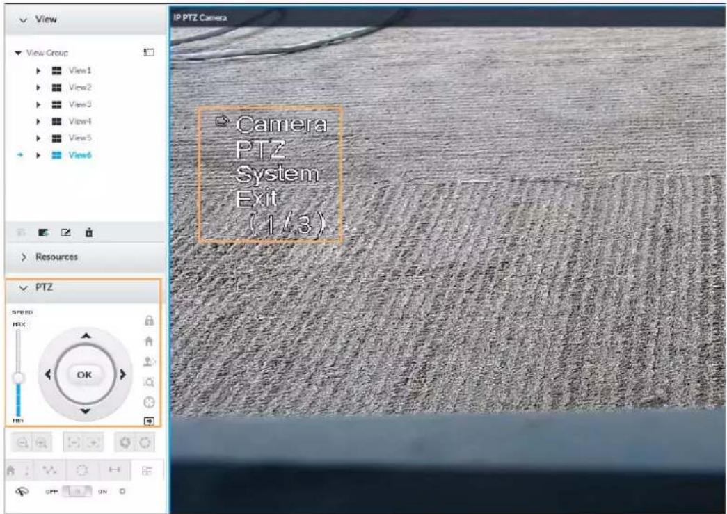
Table 7-10 PTZ menu description
| Parameters | Description |
| Camera | Set remote device image parameters involving picture, exposure, backlight, WB, day and night, focus and zoom, defog, and default. |
| PTZ | Set remote device PTZ functions such as preset, cruise, scan, pattern, rotation, and PTZ restart. |
| System | Set remote device PTZ simulator, restore default, manage remote device peripheral device, view remote device software version, PTZ version and more. |
| Exit Exit PTZ menu. |
Step 4 Set PTZ menu parameters.
- Click ▲ or ▼ to select options.
- Click ▶ or ◀ to set parameters.
- Click to confirm.
Step 5 Click ☐ to exit PTZ menu mode.
7.1.3.2 Configuring PTZ Functions
Control PTZ device to implement corresponding operations.

The PTZ functions might vary depending on the device models.
7.1.3.2.1 Setting a Preset
A preset is the saved information of a specific position, angle, and focal length of the PTZ camera. You can set a preset so that you can quickly adjust the PTZ to the desired position in the future.
Procedure
Step 1 Log in to PCAPP.
Step 2 Select a PTZ camera from the views.
Step 3 On the PTZ panel, click .

Figure 7-23 Call a preset
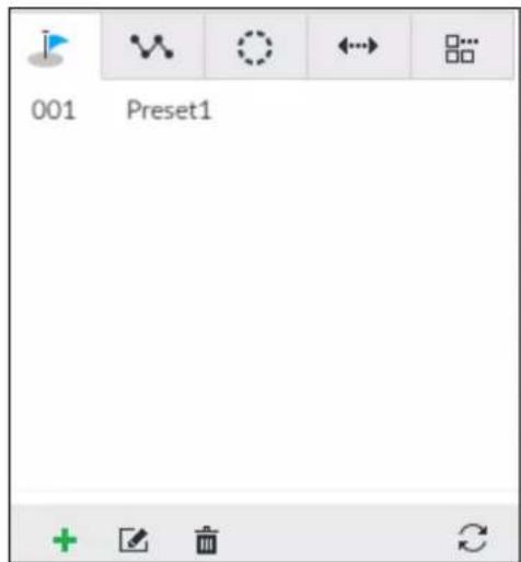
Step 4 Click the direction icons to rotate the camera to a specific position.
Step 5 Click +, enter the name of the new preset, and then click √ to save the preset.
Figure 7-24 Add a preset
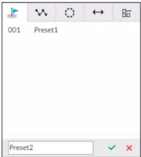
Step 6 To call the preset, hover over the preset name, and then click ▶.
Related Operations
- Edit a preset:
To edit preset name, double-click the name. The camera rotates to the preset after the double-click.
To modify the preset position, select the preset, and then click rotate the camera to the desired position, and then click √
◇ To quit, click .×
- To delete a preset, select it and then click.
- To refresh presets list, click .
7.1.3.2.2 Setting a Cruise
A cruise is a sequential set of presets. After you call a cruise, the PTZ camera automatically rotates to the presets one by one at the pre-defined interval.
Procedure
Step 1 Log in to PCAPP.
Step 2 Select a PTZ camera from the views.
Step 3 On the PTZ panel, click .
Step 4 Click +, enter the name of the new cruise, and then click √ to save.
Step 5 Click Add, select a cruise, and then click √.
Repeat this step to add multiple presets into the cruise.
Figure 7-25 Add a cruise
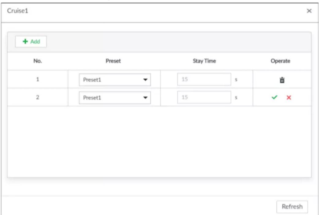
Step 6 To call the cruise, hover over the cruise name, and then click ▶. To stop the cruise, click

Related Operations
- Edit a cruise:
To edit cruise name, double-click the name. To quit, click ✗.
To modify the cruise, select the cruise, and then click ☑, modify the settings, and then click

- To delete a cruise, select it and then click .
- To refresh cruises list, click .
7.1.3.2.3 Setting a Pattern
A pattern is a recorded series of PTZ operations such as pan, tilt, zoom and focusing. You call a pattern to let the camera repeat the corresponding operations.
Step 1 Log in to PCAPP.
Step 2 Select a PTZ camera from the views.
Step 3 On the PTZ panel, click.
Step 4 To start recording a pattern, double-click on a pattern name, click Start Record, perform a series of PTZ actions as desired, and then click Stop Record.

The maximum number of patterns depends on the camera capability. If not limited on the camera, you can config up to 5 patterns by default.
Figure 7-26 Call a pattern
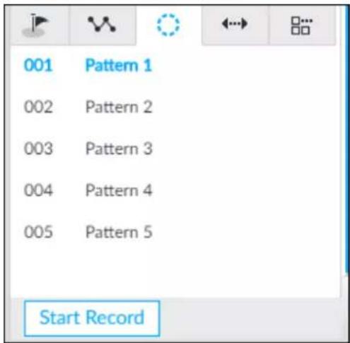
Step 5 To call the pattern, hover over the pattern name, and then click ▶. To stop, click ■.
- Edit a pattern:
- To modify the pattern, select the pattern, and then click ☑. Click Start Record and record a new pattern, and then click Stop Record. - To quit, click the pattern name.
- To delete a pattern, select it and then click.
• To refresh patterns list, click .
7.1.3.2.4 Setting Linear Scanning
In the linear scanning mode, the camera scans repeatedly to the pre-defined left and then right limit.
Step 1 Log in to PCAPP.
Step 2 Select a PTZ camera from the views.
Step 3 On the PTZ panel, click .
Step 4 Select a linear scanning, and then double-click it or click ⚙. Rotate the PTZ to the left until you think it can be the left limit, and then click ◀ to save; rotate the PTZ to the right limit, and then click ▶

The maximum number of linear scannings depends on the camera capability. If not limited on the camera, you can config up to 5 scannings by default.
Figure 7-27 Set a linear scanning
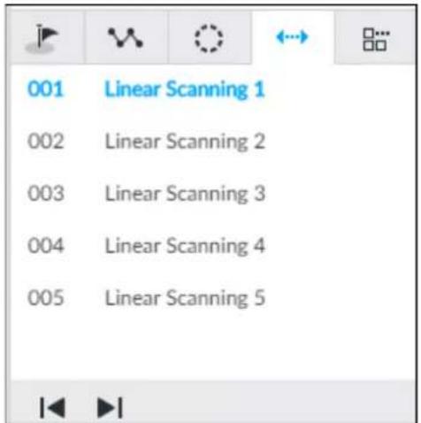
Step 5 To call the linear scanning, hover over the name, and then click ▶. To stop, click ■.
7.1.3.2.5 Enabling Auxiliary Functions
Enable PTZ windshield wiper, light and IR.
Step 1 Log in to PCAPP.
Step 2 Select a PTZ camera from the views.
Step 3 On the PTZ panel, click ☐.
Figure 7-28 Auxiliary functions
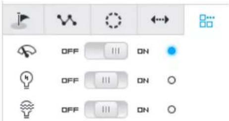
Step 4 Drag the slider to ON or OFF to enable or disable the function.
- : Windshield wiper. It is available on select models.
• : Light. It is available on select models. - : IR. It is available on select models.
7.2 Recorded Files
Search or play back the record file or image on the device. At the same time, you can export record file or image to designated storage path.
7.2.1 Playing Back Recorded Video
Search and playback record file according to remote device, record type, and record time.
Step 1 On the LIVE page, click + and then select SEARCH.
Figure 7-29 Search
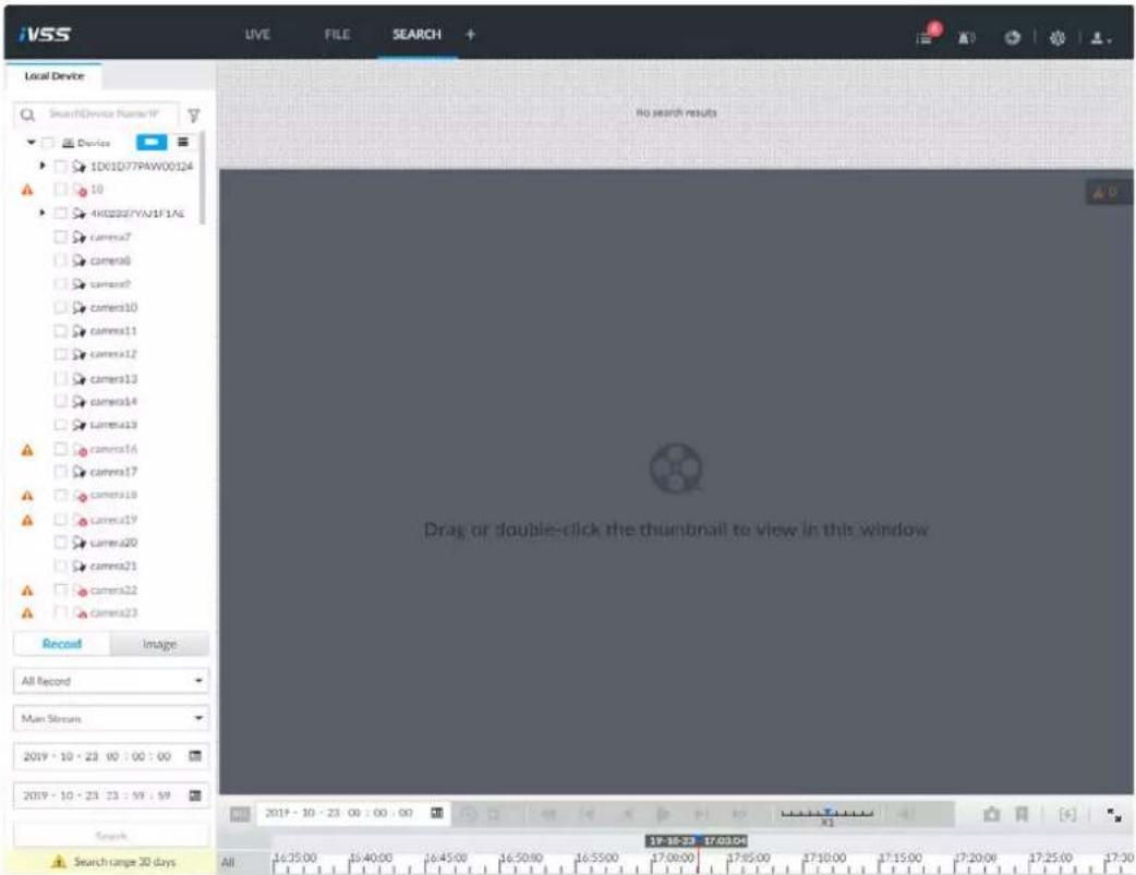
Step 2 Select a remote device, and then click Record tab.

Click ≡ to display only channels. Click ≡ to display channels and devices.
Step 3 Select a record type from among All Record, Manual Record, Video Detect, and IO Alarm and Thermal.
- All record: Search for all records.
- Instant record: Search for instant records.
- Video detect: Search for records of video detection.
• IO alarm: Search for local alarm linkage records.
• Thermal: Search for videos of thermal alarms.
Step 4 Set search time.
- Method 1: Click the date or time on the time column, change time or date value.
- Method 2: Click the date or time on the time column, use the mouse middle button to adjust time or date value.
- Method 3: Click, set date or time on the schedule, click OK.
Figure 7-30 Schedule
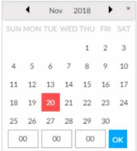
Step 5 Click Search.
The record thumbnail is at the top of the remote device, and the time bar displays the record period (green color means there is a record).

- The selected remote device is on the left panel. Click a remote device, and the record file thumbnail is on the right panel.
- Click or to move thumbnail list or hide/display the thumbnail.
- Point to the thumbnail, you can view remote device name, record start time, and end time of the corresponding record.
- Point to the thumbnail list. The system displays ↗. Click the icon to hide the thumbnail list. If the thumbnail list is hidden, click ↗ to display the thumbnail list.
Figure 7-31 Search result
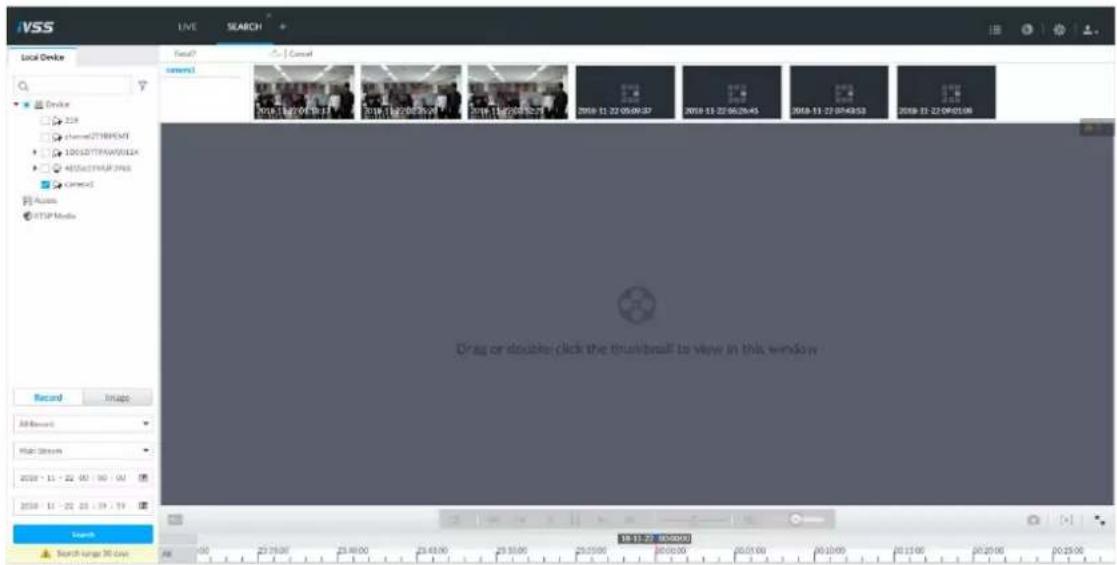
Step 6 Drag the thumbnail to the playback window or double-click the thumbnail.
Device begins playing the record.

- The playback window amount depends on the thumbnail amount you can drag or
select. System supports maximum 16 windows. System automatically adjusts each window size according to the original scale of playback file.
- The thumbnail with ▶ means system is playing record file of current thumbnail.
Figure 7-32 Search
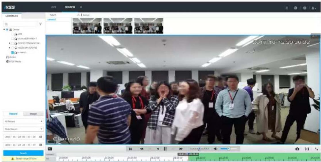
Table 7-11 Search icons description
| Signal Words | Description | |
 | Click to synchronize playback mode. You can use the playback control icon to control several windows, such as fast forward/backward at the same time.Click all to cancel synchronization operation. | |
 | Set a time period. Click to start playing the videos in the set time period. | |
| [27X8] | Play back several record files at the same time. Click the icon to switch to time synchronization mode. All other windows play the video file of the same time of current window.Click to cancel time synchronization.Click , system enables synchronization operation function. If you want to cancel synchronization, click . | |
| [TAST] | Click to play back video file at slow speed.The slow speed includes 1/2, 1/4, 1/8, and 1/16. Click the icon once, the playback speed degrades one level. | |
 | Click to switch to frame by frame backward playback.It is only valid in pause mode. | |
 | Click to play backward. Now the icon becomes II. Click II to stop backward play. | |
| [6XXT] | Click to start playback. Now the icon becomes II. Click II to pause playback video. | |
| Click to switch to frame by frame playback.[CATT]It is only valid in pause mode. | ||
| Click to play back at fast speed.The fast speed includes1, 2, 4, 8, and 16. Click the icon once, the playback speed upgrades one level. | ||
| Displays playback speed. Dragto the left or right, it is to playback at fast forward or fast backward. | ||
| Click to capture an image. | ||
| Click this icon to tag the current video. | ||
| Click to obtain one part of record, and save it in designated storage path. | ||
| Clickto mute. The icon becomes. Clickto unmute. | ||
| Click to play back at full screen. | ||
| Time bar. Displays record type and record file period.There are two record file bars on the time bar. The top bar is to display record time of selected window. The bottom bar is to display record time of all selected remote devices.The time bar adopts color to categorize record type. Green=Regular record. Red=Alarm record. Blank=No record.Time scale is to display record file date and time.System automatically adjusts time scale according to the record playback process.On the time bar, you can:Click the time bar and rotate the mouse wheel button to adjust the time accuracy.Press the time bar and then drag to the left or right. It is to move the time bar to view the hidden record time.Drag time scale to adjust start time of record playback.Click or drag the time scale to position where there is a record, system starts playing from the selected time.Click or drag the time scale to position where there is no record, system stops playing record. | ||
| Shortcut menu: Right-click on the playback window, you can view the shortcut menu. Zoom: It is to zoom in a specified zone and view the details. Original scale: It is to set view window scale. ON: System automatically adjusts video window scale according to the video resolution. OFF: System automatically adjusts video window scale according to the remote device amount and the free space on the playback panel. Audio: Set audio output. Fisheye: Set the installation method and display mode of fisheye camera. | ||
| DigitalOriginalAudio | ||
| ZoomOriginalAudioFisheye | ||
 | Select faces or humans on the video to search for similar targets. | |
 | Point to the playback window, system pops up task column. Click the icon to close the playback window. | |
7.2.2 Clipping Recorded Video
Clip one part of the recorded video, and save it in designated storage path.

Connect USB device to the system if you are on the local menu to operate.
Step 1 On the LIVE page, click + and then select SEARCH.
Step 2 Play video file.
Figure 7-33 Playback
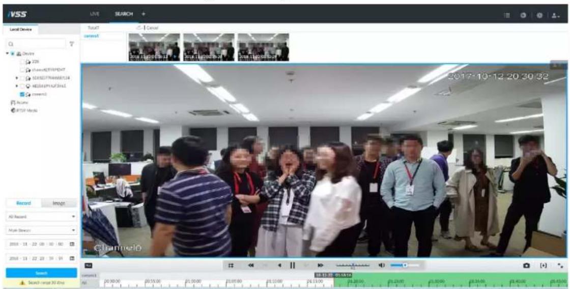
Step 3 Click. [+]
Figure 7-34 Video clipping frame

Step 4 Click the record edit column (the blue column) and drag to the left or right, to select start time and end time of clipping.
Step 5 Click Save Immediately.
Figure 7-35 Save
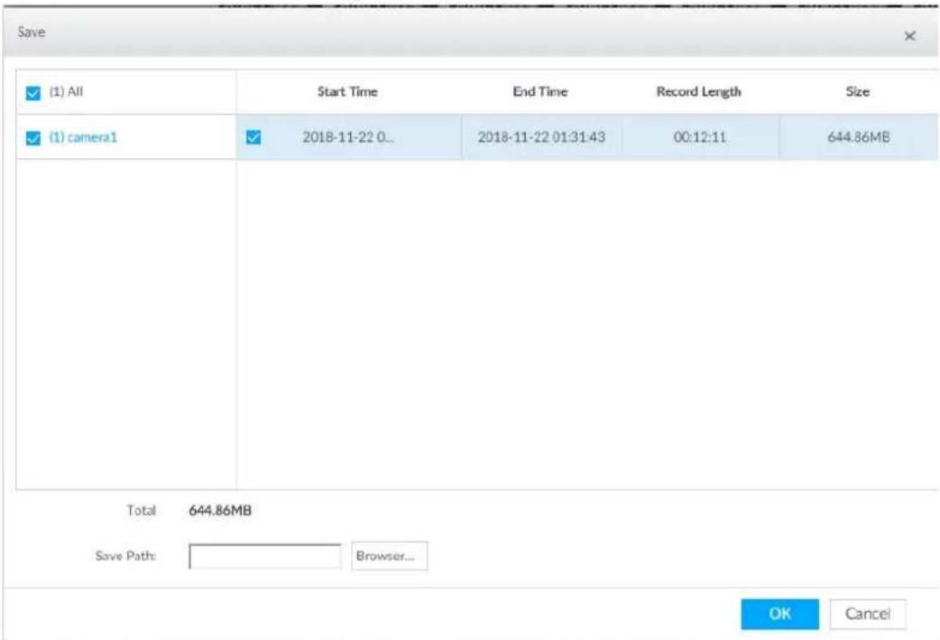
Step 6 Click Browser to select saving path.
Step 7 Click OK.
7.2.3 Playing Back Snapshots
Search and play back image according to remote device, image type, and snapshot time.
Step 1 On the LIVE page, click + and then select SEARCH.
Step 2 Select a remote device, and then click Image.

System supports maximum 1 remote device.
Figure 7-36 Image playback (1)
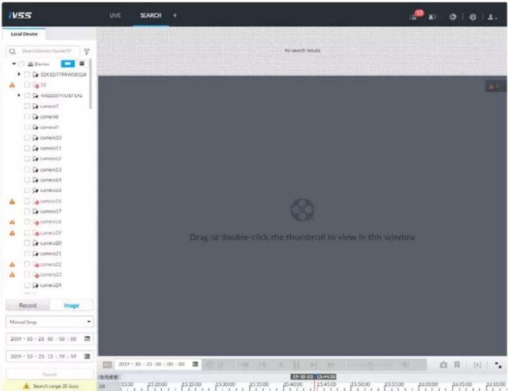
Step 3 Select image type, including Manual Snap, Video Detect, IO Alarm and Thermal.
Step 4 Set search time.
- Method 1: Click the date or time on the time column, change time or date value.
- Method 2: Click the date or time on the time column, use the mouse wheel to adjust time or date value.
- Method 3: Click, set date or time on the schedule, click OK.
Figure 7-37 Schedule
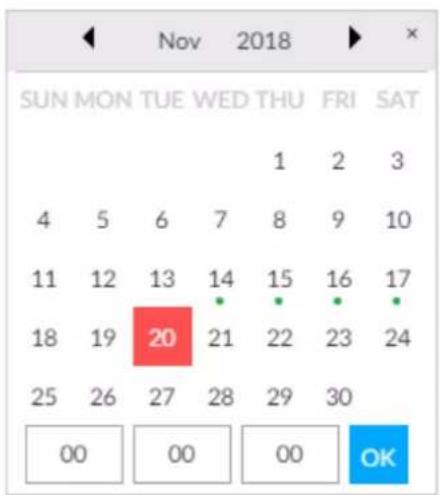
Step 5 Click Search.
Figure 7-38 Image thumbnail
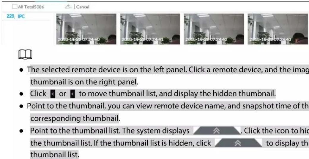
Step 6 Drag the thumbnail to the playback window or double-click the thumbnail. Device begins playing the image.
Figure 7-39 Image playback (2)
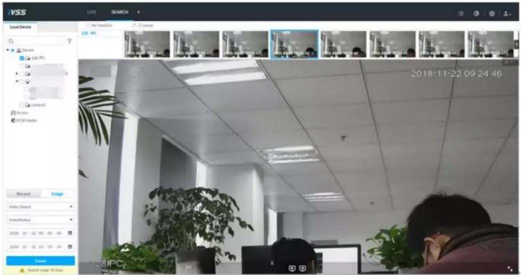

Point to the playback window, you can see the following icons.
Table 7-12 Icons
| Icon | Description |
| Click to switch to the previous image or the next image. | |
| To play one image, click to go to the previous image or the next image.To play several images at the same time, click to go to the previous group or the next group. | |
| Click to display at full screen. Click again to cancel full screen. |
7.2.4 Exporting File
Export record file or image to the designated storage path.

- The default record file mode is .dav and the image file mode is .jpg.
- Connect USB device to the system if you are on the local menu to operate.
Step 1 On the LIVE page, click + and then select SEARCH.
Figure 7-40 Search (1)
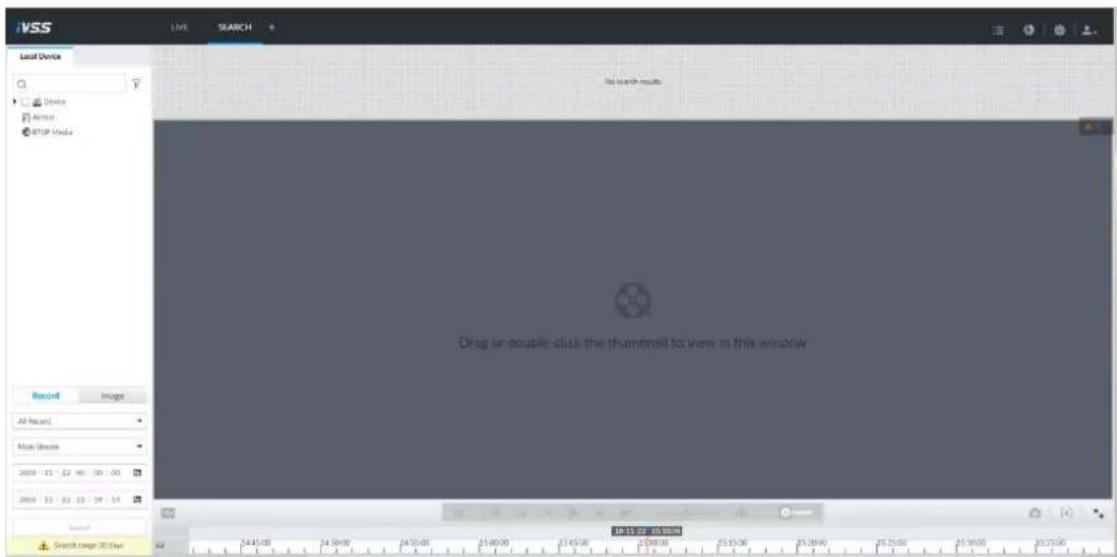
Step 2 Search record file or image.
1) Click Record or Image tab.
2) Select a remote device and then set search criteria.
3) Click Query.
Figure 7-41 Thumbnail

Step 3 Select the record file or image you want to export.
- Point to the thumbnail and then click □ to select the thumbnail. √ means checked.
- Click Cancel, it is to cancel all record files or images.
Step 4 Select file storage path.
1) Click 🔒 and then select Export record or Export image.

The following steps are to export video file. See the actual page for detailed information.
2) Click OK.
Figure 7-42 Save
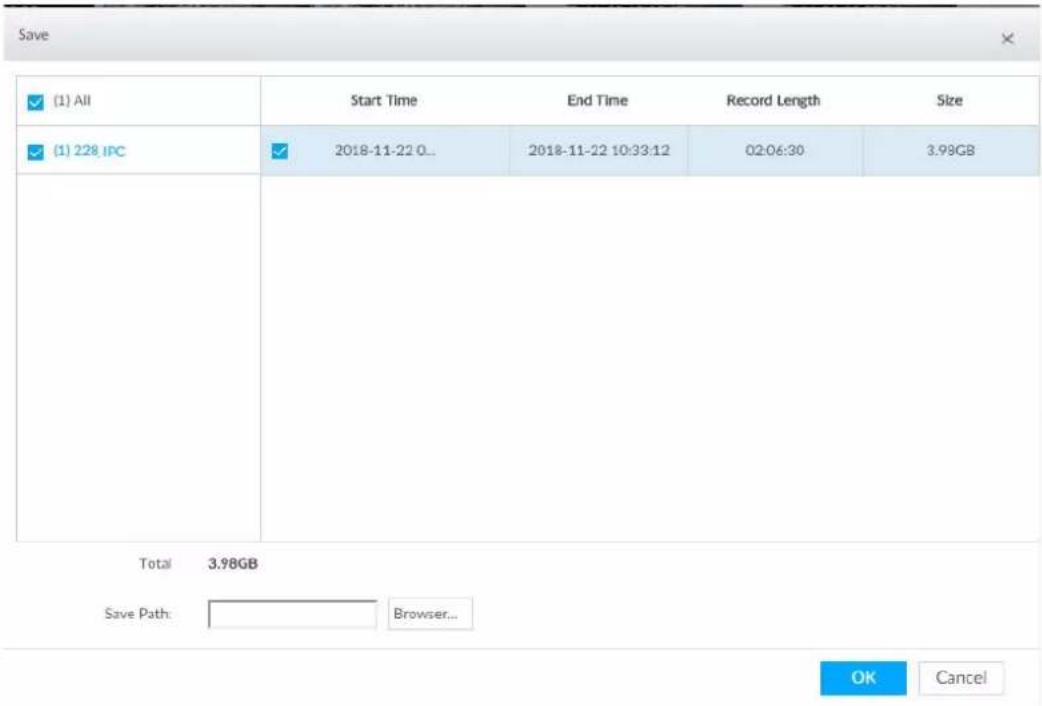
3) Click Browser to select saving path.

For local operation, after you set storage path, the Save page displays the Format button. Click the Format button to clear all data on the USB storage device. The formatting operation will clear all data. Be cautious.
4) Click OK.
Device goes back to Save page.
Step 5 Click OK.
The system starts to export files.
Figure 7-43 Download
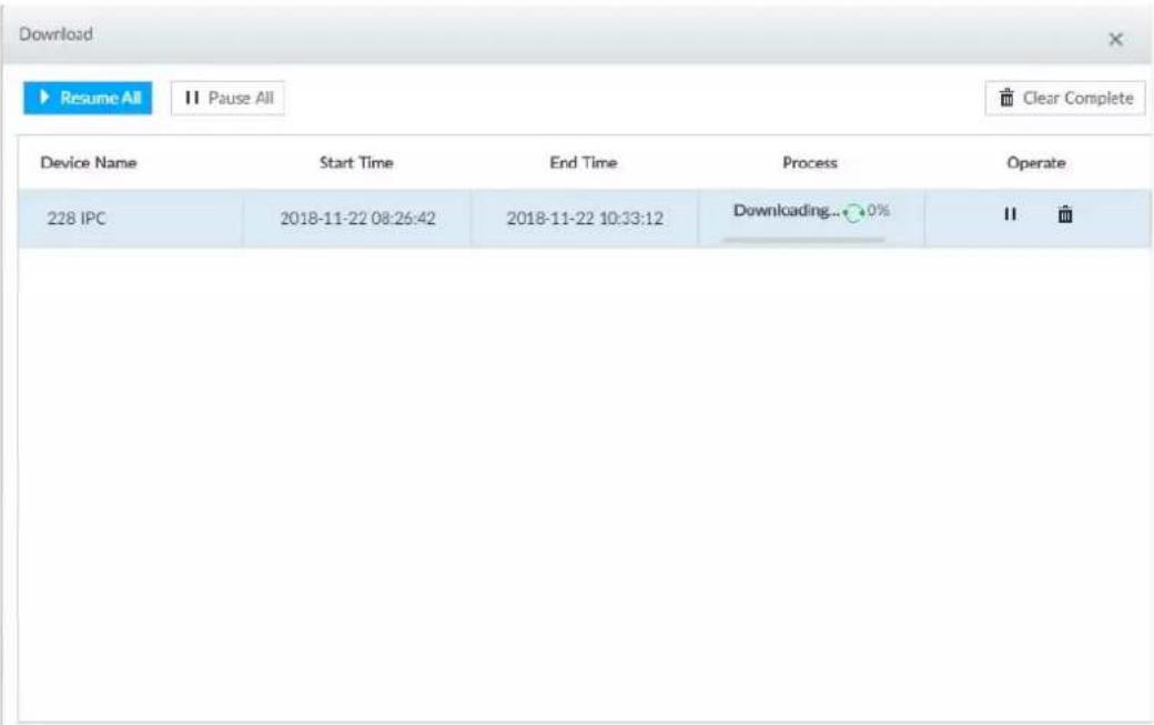
- Click Pause all to pause all download tasks. Click Start all to resume download tasks.
- Click Clear completed columns to delete all downloaded tasks.
- Click " of the corresponding task to pause download task. Click ▶ to resume download.
- Click ☐ of the corresponding task to delete download task.
7.2.5 Video Tag
Tag specific video segments or pictures for the ease of search.
Step 1 On the LIVE page, click +, and then select SEARCH.
Step 2 Search for pictures or videos.
1) Click the Record or Image tab.
2) Select a camera, and then set search conditions.
3) Click Search.
Step 3 Click ▶ at the lower-right corner of the playback window.
Figure 7-44 Tag
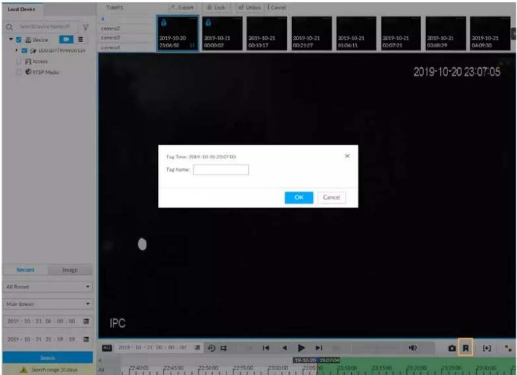
Step 4 Enter tag name, and then click OK.
7.2.6 Locking Files
Lock specific videos or pictures so they cannot be viewed. An locked file can only be viewed after being unlocked.
Step 1 On the LIVE page, click +, and then select SEARCH.
Step 2 Search for pictures or videos.
1) Click the Record or Image tab.
2) Select a camera, and then set search conditions.
3) Click Search.
Step 3 Select the video files to be locked.
- Point to the thumbnail, and then click □ to select the video.
- You can click Cancel to cancel the selected videos.
Step 4 Click Lock.
Step 5 (Optional) Click Unlock to unlock the locked videos.
7.3 File Management
7.3.1 Face Management
See "6.3.3.4 Configuring Device Face Database".
7.3.2 Vehicle Management
See "6.8.3 Configuring Vehicle Database".
7.3.3 Tag Management
Step 1 On the LIVE page, click + and then select FILE > Tag Management > Tag Management.
Figure 7-45 Tag management
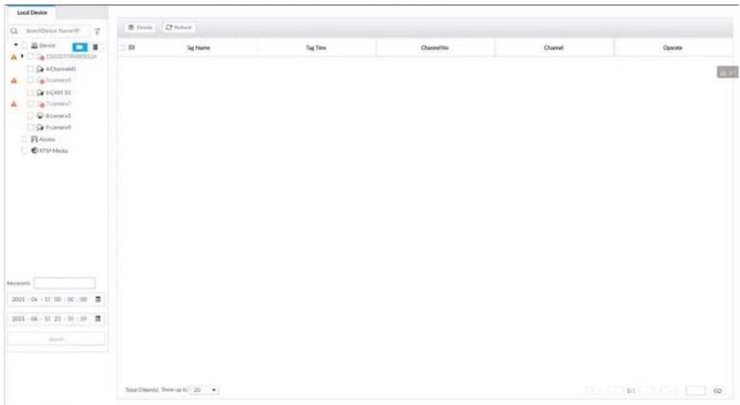
Step 2 Select a channel, set start time and end time, and then click Search.
The tags during the set time period are displayed.
- Click to view the corresponding video.
- Click to edit the tag.
- Click to delete the tag.
- Select multiple tags and click Delete to delete the tags in batches.
- Click Refresh to video the latest tags.
7.3.4 File Lock
View the locked video files, and you can unlock them.
Step 1 On the LIVE page, click +, and then select FILE > File Lock > File Lock.
Figure 7-46 File lock
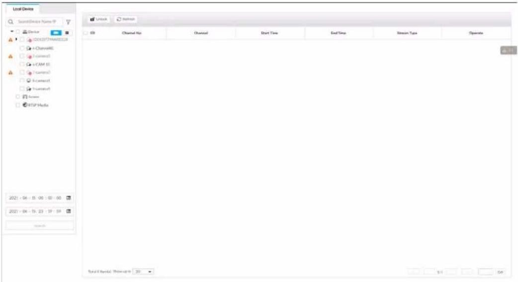
Step 2 Select a channel, set start time and end time, and then click Search.
The locked files are displayed.
- Click ⓘ to view the video of the locked file.
- Click Refresh to view the latest locked files.
- Click to unlock a file.
- Select multiple files and click Unlock to unlock the files in batches.
7.3.5 Voice Management
Upload and manage audio files, so the device plays audios in case of events.

- You can upload .pcm, .mp3, .wav,and .aac files.
- A single audio file shall not be less than 2 KB and shall not exceed 10 MB.
- Total size of imported audio files shall not exceed 200 MB.
Step 1 On the LIVE page, click + and then select FILE > Voice Manage > Voice Manage.
Figure 7-47 Audio management
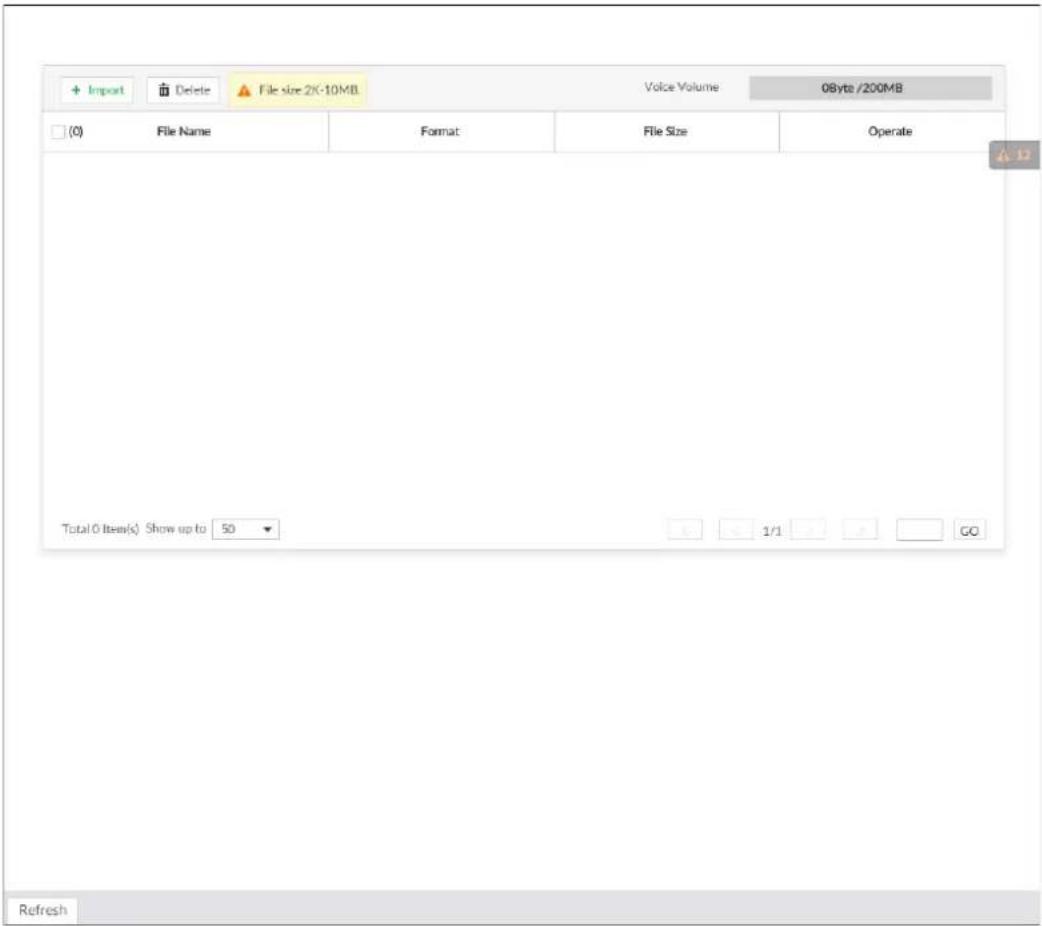
Step 2 Click Import to select the audio files that you want to import.
Step 3 Click OK.
The uploaded audio file is displayed.
After the audio file is uploaded, it can be renamed or deleted.
Table 7-13 Audio file operation
| Name | Operation |
| Rename audio file | Click ☑ to rename the audio file. |
| Delete audio file | Delete: Click beside the audio file.Batch delete: Select multiple audio files, and click Delete. |
7.3.6 Watermark Verification
Verify whether a video filed is tempered.
Step 1 On the LIVE page, click +, and then select FILE > Watermark > Watermark.
Figure 7-48 Watermark
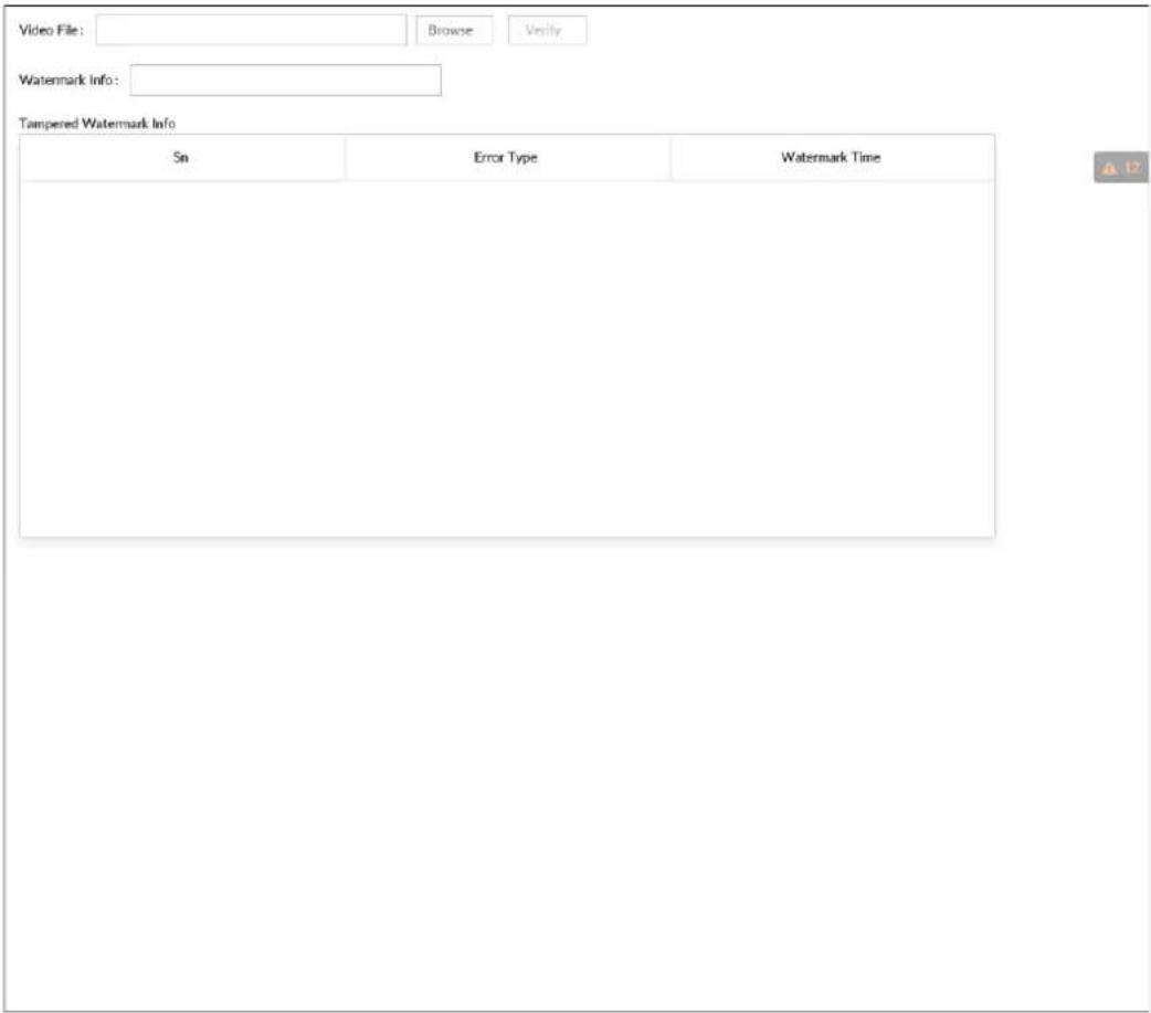
Step 2 Click Browse to select a video file.
Step 3 Click Verify.
- Normal: If the verification result is normal, the correct watermark is displayed.
- Exception: If the verification result is abnormal, the abnormal watermark and its type are displayed.
7.4 Task Management
7.4.1 AI Analysis Task
Configure AI analysis tasks for metadata of recorded videos. After the intelligent analysis task is completed, you can view the metadata video on the playback page.
7.4.1.1 Configuration Procedure
Figure 7-49 Analyze files imported from USB storage device
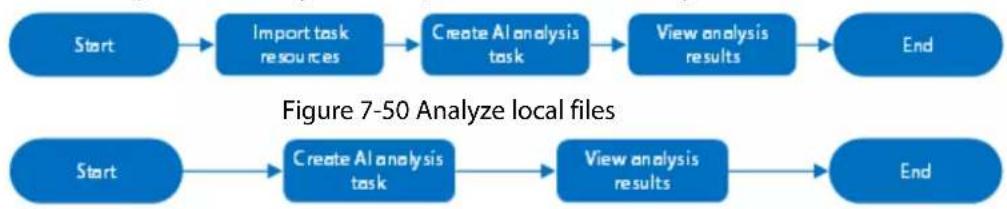
flowchart
graph LR
    A["Start"] --> B["Import task resources"]
    B --> C["Create AI analysis task"]
    C --> D["View analysis results"]
    D --> E["End"]
    F["Start"] --> G["Create AI analysis task"]
    G --> H["View analysis results"]
    H --> I["End"]
7.4.1.2 Importing Task Resources
Import task resources from PC or USB storage device for AI analysis.
Procedure
Step 1 On the LIVE page, click +, and then select TASK > Resource Management.
Figure 7-51 Resource management
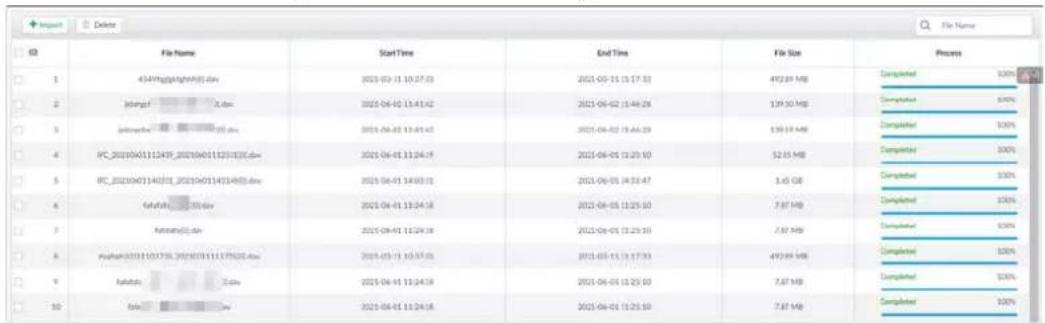
Step 2 Click Import to import .dav file from PC or USB storage device.
Related Operations
- : Delete task resources.
• : Search for task resources by file name.
7.4.1.3 Creating AI Analysis Task
Step 1 On the LIVE page, click +, and then select TASK > AI Analysis Task.
Step 2 Click Create.
Step 3 Select the files or channels to be analyzed.
- In the Video File tab, select the video files to be analyzed. The files are imported from PC or USB storage device.
- In the Local File tab, select the channels whose videos you want to analyze.

In the device tree, indicates that the camera has been configured with intelligent analysis task.
Figure 7-52 Create AI analysis task
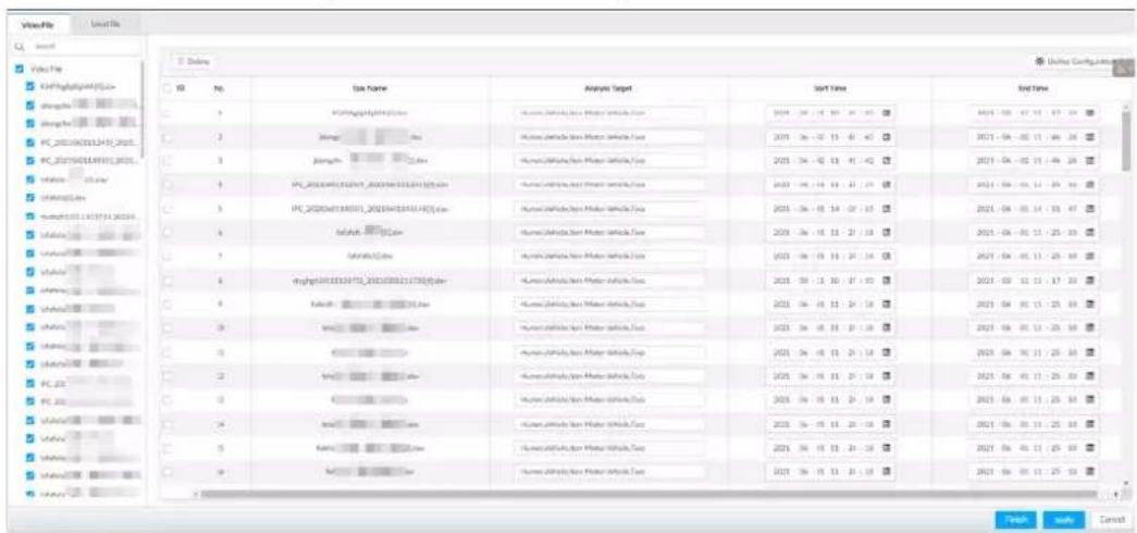
Step 4 Select a task type from Analysis Target.
1) Click the analysis target cell.
Figure 7-53 Analysis target
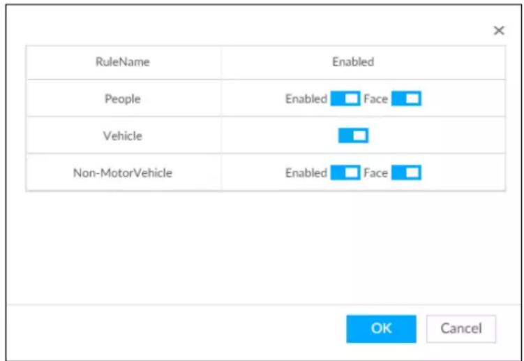
2) Select a task type.
Table 7-14 Task type description
| Rule Name | Operations |
| People | Click next to Enabled to enable human detection as well as face detection.Click next to Face to disable face detection.[HGSG]You can only enable face detection after human detection has been enabled. |
| Vehicle | Click to enable vehicle detection. |
| Non-Motor Vehicle | Click next to Enabled to enable non-motor vehicle detection as well as face detection.Click next to Face to disable face detection. You can only enable face detection after non-motor vehicle detection has been enabled. You can only enable face detection after non-motor vehicle detection has been enabled. |
3) Click OK.

Select multiple channels or video files, click Unified Configuration, and then you can configure tasks in batches.
Step 5 Select start time and end time.
Step 6 Click Finish to go back to the AI Analysis Task page.
Click apply to create more tasks on the current page.
Figure 7-54 AI analysis task
| 63 | Executive Order | Task Name | Task Type | Device Name | Channel No. | State | Process | Remaining Time | Executed Time | Analysis Target | Creation Time | Operate |
| 1 | 22.2050727141749_1 | Video File | - | - | Completed | 100% | Oms. | 2min:Sec. | 2021/09-07 18:33:03 | |||
| 2 | 1 | Local File | 1 | 30 | Completed | 100% | Oms. | 3hr 25min:48sec. | 2021/09-07 21:05:59 | |||
| 3 | Local File | 40 | Completed | 100% | Oms. | 3hr 35min:14sec. | 2021/09-07 25:06:42 | |||||
| 4 | 17 | Local File | 17 | 1 | Completed | 100% | Oms. | 3hr 3 min:1 sec. | 2021/09-06 14:33:29 | |||
| 5 | 113 | Local File | 113 | 5 | Completed | 100% | Oms. | 3hr 25min:34sec. | 2021/09-08 18:26:24 |

After an AI analysis task is created, the Device automatically runs analysis within the defined execution period. During the period, real-time AI analysis is suspended.
On the AI Analysis Task page, you can perform the following operations.
Table 7-15 Task operations
| Function | Operation |
| Click to start a task. | |
| Click to delete a task. | |
| Click to download the task video. | |
| Click to play back video of the task. | |
| Click to increase the priority of the task. | |
| Click to lower the priority of the task. | |
| Start Select tasks, and then click Start to start the tasks in batches. | |
| Pause Select tasks, and then click Pause to pause the tasks in batches. | |
| Delete Select tasks, and then click Delete to delete the tasks in batches. | |
| Execution Period | Select one or more tasks, click Execution Period, and then select a time period. Tasks automatically run during this time period. |
7.4.1.4 Viewing Analysis Results
On the LIVE page, click + and then select AI SEARCH. On the AI Search page, you can view analysis results.
- If the analysis target is Human, see "6.5.4.1 Human Search".
- If the analysis target is Vehicle, see "6.5.4.2 Vehicle Search".
- If the analysis target is Non-motor Vehicle, see "6.5.4.3 Non-motor Vehicle Search".
- If the analysis target is Face, see "6.3.2.6 Face Search".
7.4.2 Extracting Eigenvector Again
Re-extract Eigenvector of images with unmatched versions, to improve AI analysis accuracy.

The Extract Eigenvector Again function is triggered automatically after Eigenvector model is updated. After the model version update, the system re-extracts face databases and passerby databases first and then hot data. The hot data includes history capture data.
Step 1 Log in to PCAPP.
Step 2 On the LIVE page, click + and then select TASK > Extract Eigenvector Again.
Step 3 Click □ to enable the function.
Figure 7-55 Extract Eigenvector Again

Step 4 Specify the start time and end time of the day.
- The system automatically creates tasks to re-extract Eigenvector of history images with unmatched model versions during the period.
- During the re-extraction period, the AI functions are not available.
7.5 Backup
Step 1 On the LIVE page, click +, and then select BACKUP.
Figure 7-56 Backup
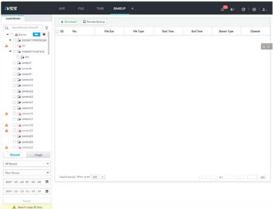
Step 2 Select a channel from the resource tree on the left.
Step 3 Select a file type.
- Record
1) Select a record type from All Record, Instant Record, Video Detect and IO Alarm.
2) Select a stream type from Main Stream and Sub Stream.
3) Set the time period. - Image
1) Select an image type from Manual Snap, Video Detect, and IO Alarm.
2) Select a stream type from Main Stream and Sub Stream.
3) Set the time period.
Step 4 Click Search.
Step 5 Back up files by downloading or remote backup.
- Download
1) In the search results, select one or more files, and then click Download.
Figure 7-57 Save
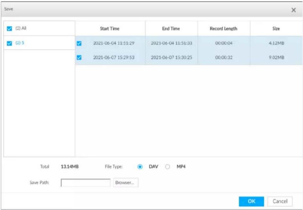
2) Select a file type.
3) Click Browse to set saving path. You can download files to PC or USB storage device.

When downloading to USB storage device, making sure that the USB device has already been connected to the Device.
4) Click OK.
- Remote backup
1) In the search results, select one or more files, and then click Remote Backup.
Figure 7-58 Remote device
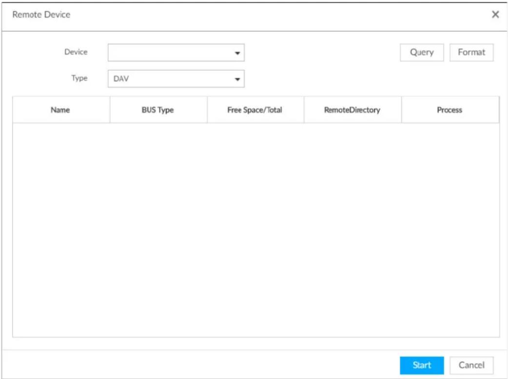
2) Click Query to search for connected third-party storage devices.
3) Select a storage device, and then in the Type box, select a target format for the file.
4) Click Format to format the selected storage device. The formatting operation will clear all data of the storage device. Be cautious.
5) Click Start.

Make sure that external HDD or disk array enclosure has been connected to the eSATA port of the Device.
7.6 Alarm List
Click 🔒 to display alarm list. You can view alarm device name, alarm time and alarm type.
Figure 7-59 Alarm list
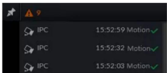
- Number 9 is the number of alarm event to be processed. The value changes according to alarm amount. It displays maximum 200 unprocessed alarm events.
-
Click 📋 to lock alarm list. The alarm list is open and cannot hide. Click the icon again to cancel lock function. Point to other position, and the alarm list displays for a period of time and then automatically hides.
-
Click √ to confirm alarm event. The confirmed event will be removed from the alarm list.
- Click the alarm event on the alarm list. The device displays the 20 seconds video before and after the alarm event occurred.
◇ Click III to pause play. Now the icon becomes ▶. Click ▶ again to continue to play.
◇ Click OK and close, confirm the alarm event and then exit the page.
Figure 7-60 Alarm video
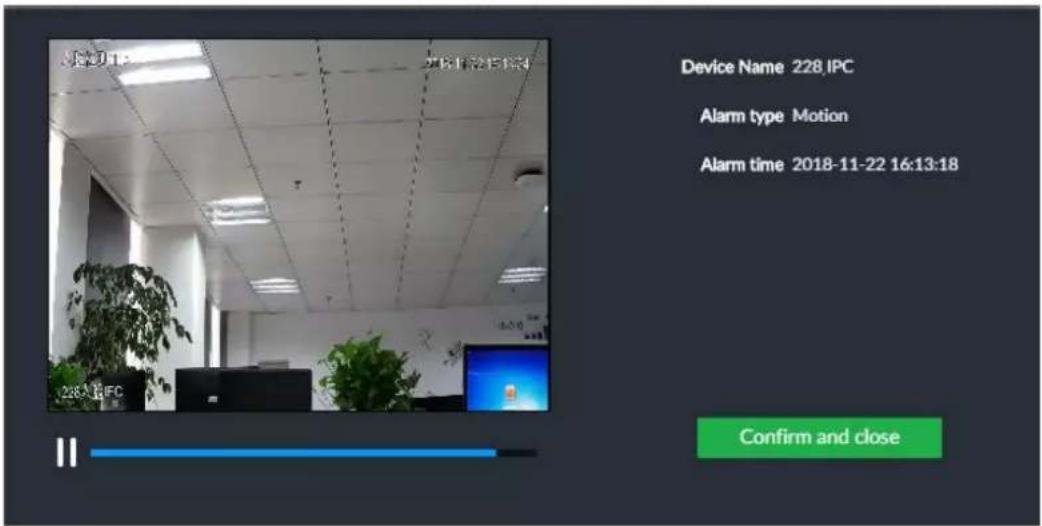
7.7 Display Management
Enable connected display or lock the screen.
7.7.1 Multiple-screen Control
Device can connect to multiple displays at the same time. You can select a display you want to use.

- The multiple-screen control function is for local menu only.
- Enter Display Output page, you can enable a display or set its resolution. See "8.8.3 Display" for detailed information.
- The page might vary since the connected display amount is not the same.
Click
- SN 1–3 represent displays connected to HDMI 1–HDMI 3. The main screen refers to the device connected to VGA and HDMI 1 port. The displays connected to the HDMI 2 and HDMI 3 are the sub screens. The output interfaces of main screen and the sub screen are not the same and the supported functions are different.
- VGA and HDMI 1 are outputting the same video source. Three HDMI ports can output different video sources.
- means connected and enabled display. - means connected but not enabled display.
- Click ☐ or ☐ to disable or enable display. Device adopts main screen by default and the main screen cannot be disabled.
Figure 7-61 Display
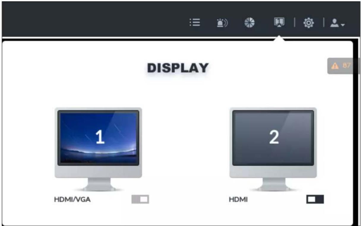
Table 7-16 Difference between main screen and sub screen
| Name | Main screen | Sub screen | |
| Function Operations | User operation (Login, log out, change password, lock) | Yes Yes | |
| Preview and Monitor Yes Yes | |||
| Search Yes Yes | |||
| Confirm alarm | Yes | No | |
| File Management Yes Yes | |||
| Intelligent Analytics Yes Yes | |||
| Multiple-screen control | Yes No | ||
| System Info Yes Yes | |||
| Background Task Yes Yes | |||
| Operation and Maintenance Management | Yes Yes | ||
| Device Operation (Reboot, shut down) | Yes No | ||
| System Configuration | Device, network, event, storage, account, security strategy, and system management, and cluster. | Yes No | |
7.7.2 Locking Screen
Click 📁 and then select Lock to lock the screen. The screen stops at current page and cannot operate other functions.
If you want to unlock the screen, click any position on the screen, enter password or user other account to login.
Figure 7-62 Unlock screen
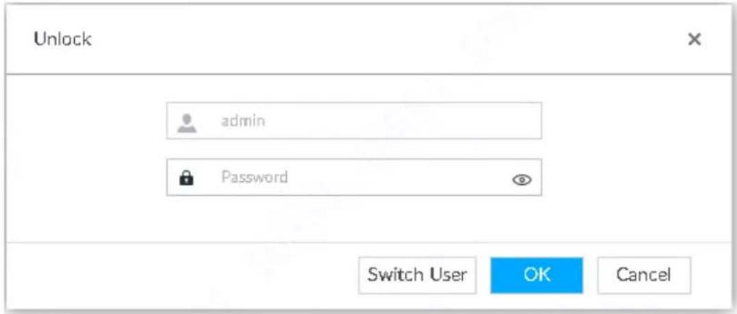
7.8 System Info
View system information including system error, system alarm and system notification.
Click ☐ to display background task list.
Figure 7-63 System info
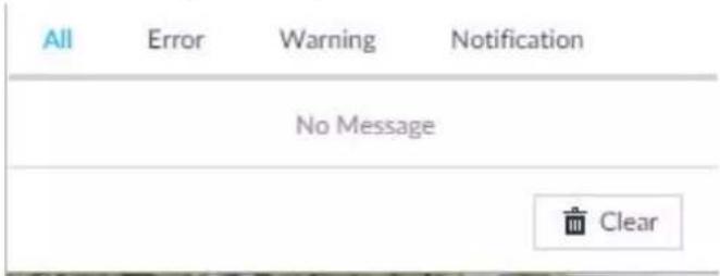
- Click All, Error, Warning, or Notification tab to view the corresponding system information list.
- Click ☐ to clear the corresponding system information.
- Click Clear to clear system information under current tab.
For example, click All tab and then click Clear button to clear all system information. Click Error tab and then click Clear button to clear all system error information.
7.9 Background Task
View background task running status.
Click 📄, device displays background task list. Click All, Running, or Waiting to view the corresponding background task list.
Figure 7-64 Background task
7.10 Buzzer
View buzzer alarm messages.
Click The alarm messages are displayed.
Figure 7-65 Buzzer
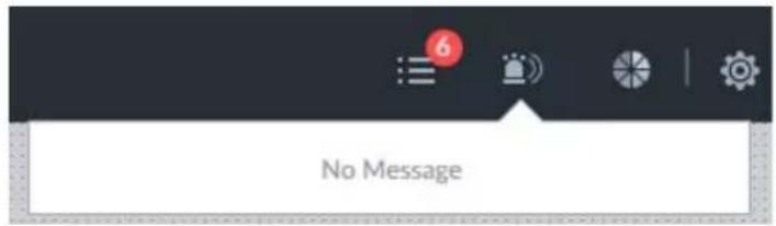
8 System Configuration
This chapter introduces system configuration functions such as managing remote device, setting network, setting alarm event, setting HDD storage, managing user information, setting device security strategy, and setting system parameters.
8.1 Configuration Window
Click 📍 to open the configuration window.
Figure 8-1 Configuration window
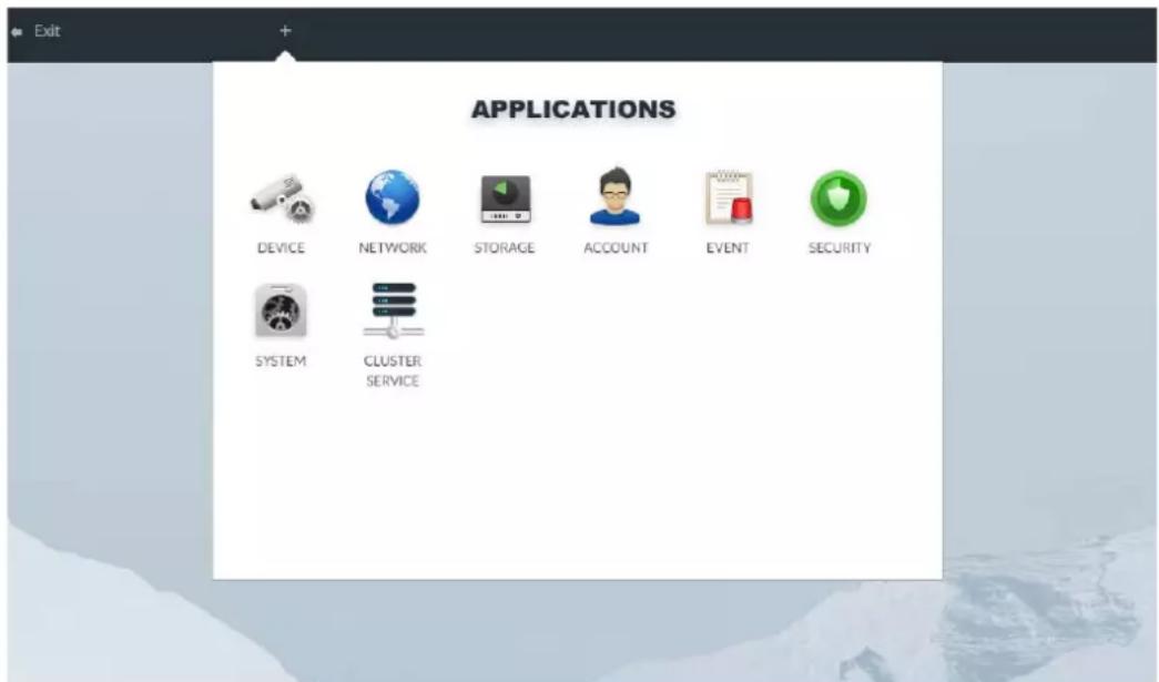
On this window, you can:
- Click the corresponding app icon to go to the corresponding page. The task column displays current running app name. Point to the app name and then click ✗ to close the app.
- Click Exit to exit the page.
8.2 Device Management
Click 📍 or click + on the configuration page, and then select DEVICE. The DEVICE page is displayed. You can set the Device or remote devices.
- Select the root node ▼ 456 in the resource tree to set IVSS name and storage plan.
- Select a remote device in the device list. Set its property, connection, video, OSD, and storage plan.
Figure 8-2 Device management
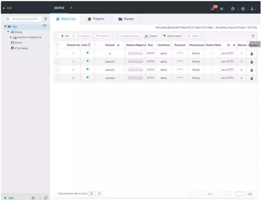

Click + or click Add to add remote device to the system.
8.2.1 Viewing Device Information
View information of the Device.
Step 1 Click 📋, and then select DEVICE.
Step 2 Select the root node ▼ 456 in the resource tree, and then click the Device Info tab.
Step 3 Set parameters.
Figure 8-3 Device information
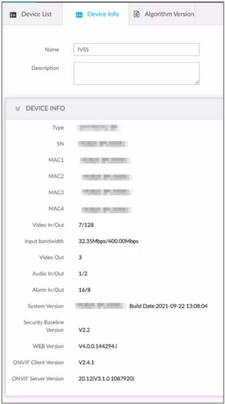
Table 8-1 Device info
| Parameters | Description |
| Name Set device name. | |
| Description | Device description. |
| Device info | Displays device info, including type, SN, MAC, number of video, audio and alarm in/out channels, video input bandwidth, system version, security baseline version, web version, and algorithm version. |
Step 4 Click Save.
8.2.2 Remote Device
The Device supports to add remote device, modify its IP address and configurations, and export its information.
8.2.2.1 Viewing Remote Devices
View connected remote devices. For details about adding devices, see "8.2.2.3 Configuring Remote Devices".
Step 1 Click 🎨, or click + on the configuration page, and then select DEVICE.
Step 2 Select the root node ▼ in the resource tree, and then click the Device List tab.
Figure 8-4 Device list
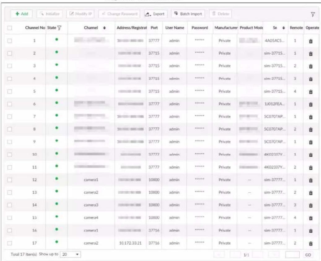
Step 3 View details of connected devices, including IP address and serial number.
- In the Status column, ● indicates that the device is offline.
- In the Status column, ● indicates that the device is online.
- In the Status column, ⚠ indicates that the device is in exception. Point to ⚠, and then you are prompted about the details of the exception, such as being uninitialized, device mismatch, and wrong password.
Step 4 (Optional) Click to set filtering conditions for search.
8.2.2.2 Changing IP Address
Modify IP address of the remote device connected or not connected to the Device.
8.2.2.2.1 Modifying IP of Unconnected Devices

- You can only modify the IP address of initialized devices.
- You can only modify the IP address of remote devices connected with private protocol.
Step 1 Click 🎨 or click + on the configuration page, and then select DEVICE.
Step 2 Click + or click Add, and then select Smart Add.
Step 3 Click Start Search. System starts to search and displays result.
Figure 8-5 Remote device
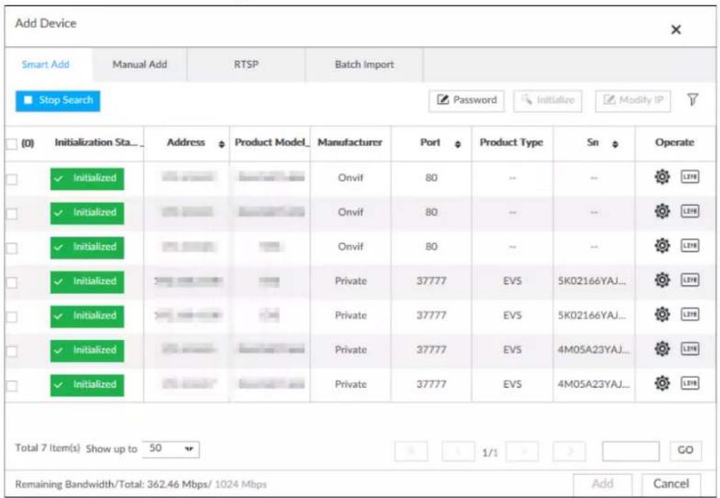
Step 4 Select a remote device and then click Modify IP.
Figure 8-6 Modify IP (1)
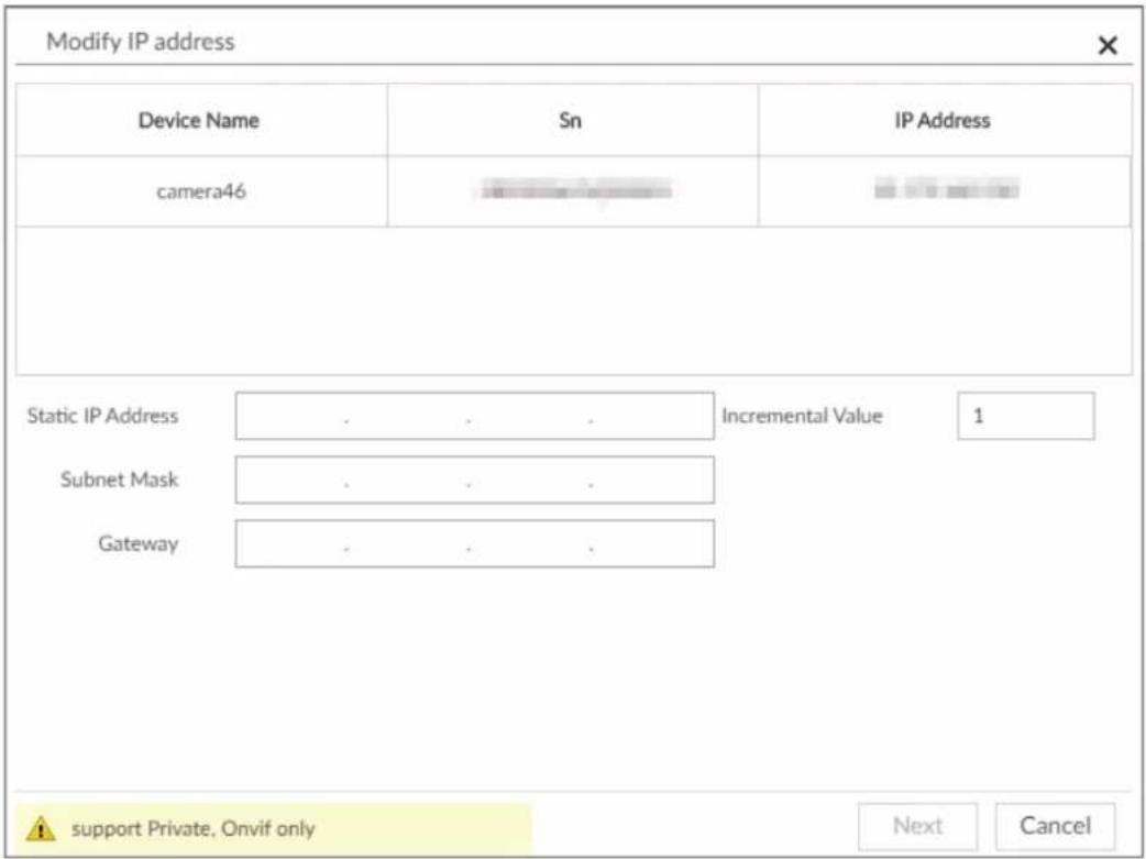
Step 5 Enter the static IP address, subnet mask, gateway, and incremental value.

- Enter incremental value only when multiple remote devices are modified. If you want to change IP addresses of several devices at the same time, system allocates IP address one by one according to your setting at the fourth bit of the IP address. - If there is IP conflict when changing static IP address, device pops up IP conflict dialogue box. To change IP addresses in batches, system automatically skips the conflicted IP and begins the allocation according to the incremental value.
Step 6 Enter the username and password of remote device.

When you are changing several device IP addresses, make sure that the username and password of these remote devices are the same.
Step 7 Click Next.
The modification result is displayed.
Step 8 Click OK to complete the modification.
8.2.2.2.2 Modifying IP of Connected Devices

- You can only modify the IP address of initialized devices. For remote device initialization, see "5.4.1 Initializing Remote Device" for detailed information.
- You can only modify the IP address of remote devices connected through Private, Onvif or Onvifs protocol.
- To modify the IP address of connected devices one by one, see "8.2.2.3.2 Configuring Connection
Information".
Step 1 Click 🎨, or click + on the configuration page, and then select DEVICE.
Step 2 Select a remote device and then click Modify IP.
Figure 8-7 Modify IP (1)
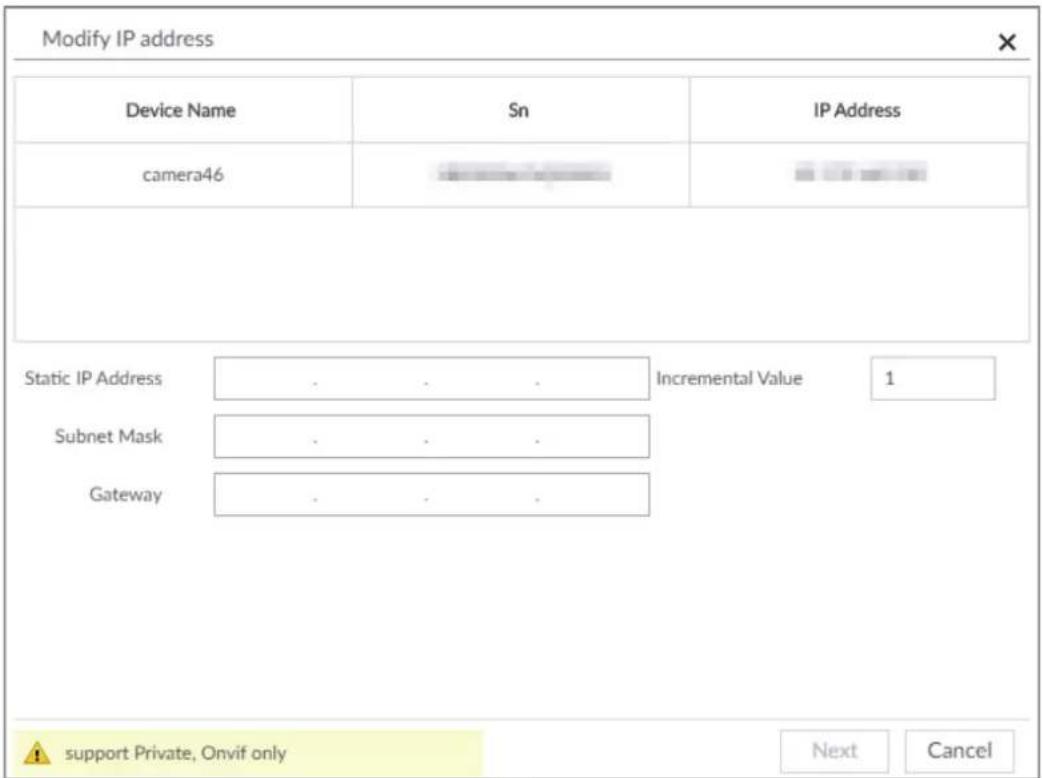
Step 3 Enter the IP address, subnet mask, gateway, and incremental value.

- Enter incremental value only when multiple remote devices are modified. If you want to change IP addresses of several devices at the same time, system allocates IP address one by one according to your setting at the fourth bit of the IP address.
- If there is IP conflict when changing static IP address, device pops up IP conflict dialogue box. To change IP addresses in batches, system automatically skips the conflicted IP and begins the allocation according to the incremental value.
Step 4 Enter the username and password of remote device.

When you are changing several device IP addresses, make sure that the username and password of these remote devices are the same.
Step 5 Click Next.
The result of IP modification is displayed.
Step 6 Click OK.
8.2.2.3 Configuring Remote Devices
Set remote device property, connection information, and video parameters.

The page displayed might vary with remote devices. See the actual page for detailed information.
8.2.2.3.1 Configuring Device Property
Set remote device name, and view device information.
Step 1 Click ⚙, or click + on the configuration page, and then select DEVICE.
Step 2 Select a remote device on the left panel and then click Property tab.
Figure 8-8 Property
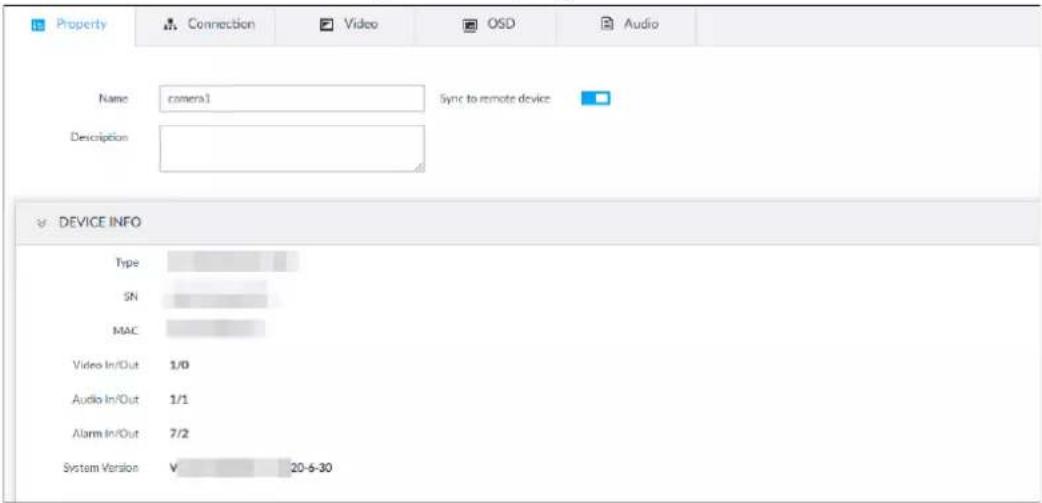
Step 3 Set parameters.
Table 8-2 Property parameters description
| Parameters | Description |
| Name | Set remote device name.Enable Sync to remote device and save the settings to synchronize new name to the remote device. |
| Description | Input remote device description. |
| Device info | Displays remote device information. It includes remote device type, SN, MAC address, video in/out, audio in/out, alarm in/out, and system version. |
Step 4 Click Save.
8.2.2.3.2 Configuring Connection Information
Set connection information of remote device, such as IP address and port number.
Step 1 Click 🎨, or click + on the configuration page, and then select DEVICE.
Step 2 Select a remote device on the left panel and then click the Connection tab.
Step 3 Change IP address.
1) Click ☑ of the corresponding address.
2) Enter IP address, subnet mask and gateway.
3) Click Test to test whether the IP address is valid.
Figure 8-9 Modify IP
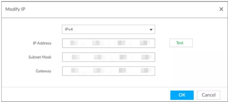
4) Click OK to save setting.
Step 4 Change port number.
1) Click ☑ of the corresponding port.
Figure 8-10 Port
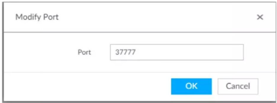
2) Change port number.
3) Click OK to save setting.
Step 5 Set other parameters.
Table 8-3 Connection parameters description
| Parameters | Description |
| Manufacturer | Displays the connection protocol of the remote device. |
| Username | Enter username and password of remote device. |
| Password | |
| Link type | Displays link type of the system and remote device. It is self-adaptive. |
| Cache strategy | Set cache strategy of remote device video stream.Self-adaptive: System automatically adjusts video stream cache status according to the network bandwidth.Realtime: Guarantee video real-timeness. When the network bandwidth is not sufficient, the video might not be fluent.Fluency: Guarantee video fluency. When the network bandwidth is not sufficient, the video might not be clear. |
Step 6 Click Save.
Step 7 (Optional) Click e, and then you can go to the web interface of the remote device.

On the local interface of the Device, you cannot click 📔 to go to the web interface of the remote device.
8.2.2.3.3 Configuring Video Parameters
Set different video parameters according to different bit stream types based on the bandwidth.
Step 1 Click 🎨, or click + on the configuration page, and then select DEVICE.
Step 2 Select a remote device on the left panel and then click Video tab.
Figure 8-11 Video
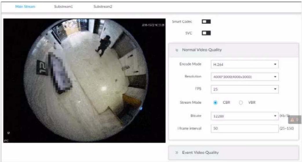
Step 3 Set main stream, sub stream 1, or sub stream 2.
Step 4 Set general video quality parameters.
Table 8-4 Video parameters description
| Parameters | Description |
| Smart Codec | Enable this function to enhance performance of video compression and thus reduce storage space requirement.This function is only available for main stream. |
| SVC | Select the checkbox to enable SVC function. Select 1 or 2 from the drop-down list on the right. The default setup is 1, there is no scaled encoding.SVC refers to the scaled video coding. It can split the video stream to basic stream and enhanced scale. |
| Encode mode | Set video encode mode.H.264: It is a highly compressed video encoding or encoding standard. At the same video quality, it has increased the compression rate by 2X compared with the MPEG-2.H.265: It is a new video encode standard coming after H.264. It has improved the complicated relationship among bit stream, encode quality, latch and algorithm on the previous standard. It can get the best encoding. |
| Resolution | Set video resolution. The higher the resolution is, the better the video quality is.[W7X2]Different series products support different resolutions. See the actual page for detailed information. |
| FPS | It is to set the frame amount displayed at each second. The higher the frame rate is, the more vivid and fluent the video is. |
| Stream mode | Set video bit stream control mode.CBR: The bit stream changes slightly. The bit stream is near the value you set here.VBR: The bit stream might change according to the environment. |
| Quality | Set video quality. It includes low, middle, high. It is null when the stream mode is CBR. It is null when the stream mode is CBR. |
| Bitrate | Set video bitrate.Main stream: In the Bit Rate list, select a value or enter a customized value to change the image quality. The bigger the value is, the better the image will become.Sub stream: In CBR mode, the bit stream changes around the value you set. In VBR mode, it changes according to the bit stream value, but its max value is near the specified value. |
| I frame interval | Set the P frame amount between two I frames. Usually we recommend it is the 2X of the frame rate. |
Step 5 Enable Event Video Quality and set FPS and stream mode.

Event video quality is for main stream only.
Step 6 Click Save.
8.2.2.3.4 Configuring OSD
Set time and channel information overlay on the video.
Step 1 Click ⚙, or click + on the configuration page, and then select DEVICE.
Step 2 Select a remote device on the left panel and then click OSD tab.
Figure 8-12 OSD
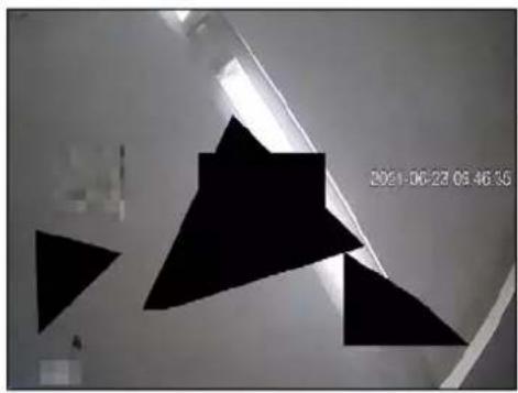
natural_image
Abstract black geometric shapes on a white wall, no text or symbols visible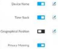
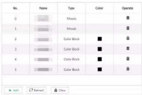
Step 3 Enable OSD information according to actual requirements.
- Set device name
- Click □ to enable OSD of device name.
- Click .
- Enter device name.
Figure 8-13 Device name
IP PTZ Camera
- Drag the text box to the proper position.
- Click ☐ to save the OSD information.
- Set device name
- Click □ to enable OSD of time.
- Click .
Figure 8-14 Time
2018-11-20 14:25:34
- Drag the text box to the proper position.
- Click ☐ to save the OSD information.
- Set geographical position
- Click □ to enable OSD of geographical position.
- Click .
- Enter the geographical position information.

Click to adjust the alignment of text boxes.
◇ Click 曾 or 甲 to create a text box.
◇ Click to delete a text box.
Figure 8-15 Geographical position
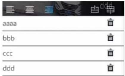
- Drag the text box to the proper position.
- Click ☐ to save the OSD information.
- Set privacy masking

This function is available only when the camera supports privacy masking.
- Click □ to enable privacy masking.
- Click Add, select the masking type and color, and then draw mosaic or color blocks in the image as needed.
- Drag blocks to the proper position.
- Click to save the OSD information.
Step 4 Click Save.
8.2.2.3.5 Configuring Audio Parameters
Step 1 Click 🎨, or click + on the configuration page, and then select DEVICE.
Step 2 Select a remote device on the left panel and then click Audio tab.
Figure 8-16 Audio
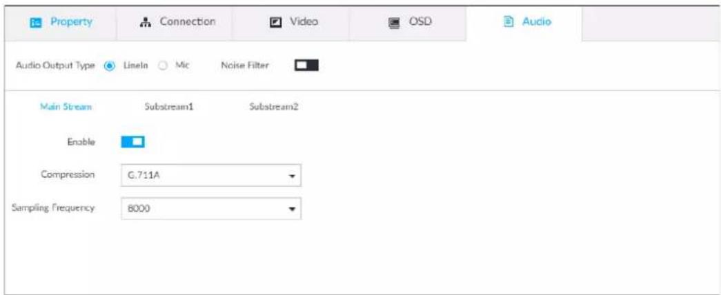
Step 3 Select an audio output type.
• Lineln: The Device acquires audio signals through external audio device.
- Mic: The Device acquires audio signals through internal mic.
Step 4 Click □ to enable Noise Filter.
Step 5 Click the Main Stream, Substream1 or Substream2 tab, and then configure the parameters.
Table 8-5 Audio parameters
| Parameter | Description |
| Compression | The audio encoding mode set here applies to both audio streams and voice talks. We recommend leaving it as default. |
| Sampling Frequency | The number of samples of a sound that are taken per second. The higher the value, the more accurate the digital representation of the sound can be. |
Step 6 Click Save.
8.2.2.4 Exporting Remote Devices in Batches
Export the added remote device. When the device restores factory default settings or information of remote device is lost, export information of remote device to recover quickly.

See "5.4.2 Adding Remote Device" for detailed information.
Step 1 Click 🎨 or click + on the configuration page, and then select DEVICE.
Step 2 Click ↗ at the lower-left corner.

Click Download Template to download template file of the remote device, and add remote device through the template.
Figure 8-17 Export
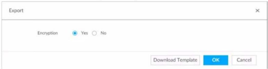
Step 3 Select encryption or not.
- If you select Yes, the system exports encrypted .backup file.
- If you select No, the system exports .csv file, which can be opened with Excel. The exported .csv file contains IP address, port number, channel number, channel name, manufacturer and username (excluding password) of the remote device.

When unencrypted file is exported, keep the file properly to avoid data leakage.
Step 4 Click OK.
Step 5 Click Save.
File path might be different depending on your operations.
- On PCAPP, click, select Download to view file saving path.
- Select file saving path during local operation.
- During web operations, files are saved under default downloading path of the browser.
8.2.2.5 Importing Remote Devices in Batches
Import devices in batches by using the template.
On the Device List page, click Batch Import to go to the Add Device page. On the Add Device page, click the Import CSV File tab.
8.2.2.6 Connecting Remote Devices
On the Device page, view connection status of remote device in the device list.
When the remote device name and icon is black, SDT5A403 for example, it means the remote device is online. When they are gray, C2 8249 for example, it means the remote device is offline.
- Right-click the offline device, and then select Connect to connect the device.
- Right-click the online device, and then select Disconnect to disconnect the device.
- Right-click the online device, and then select Open WEB to go to the web interface of the device.
Figure 8-18 Device list
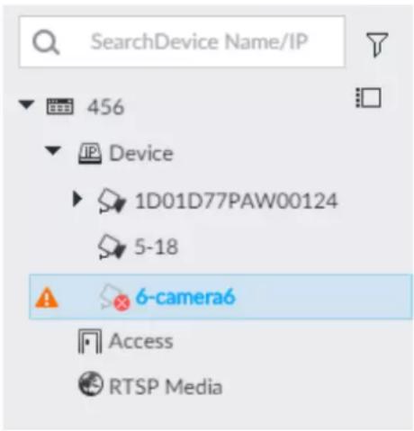
8.2.2.7 Deleting Remote Devices
On the Device page, delete the registered remote device.
- Delete one by one:
◇ Select a remote device and then click 🔒 to delete.
On the Device List page, right-click a remote device and then click Delete.
On the Device List page, select a remote device, and then click ☐.
On the Device List page, select a remote device, and then click Delete.
- Batch delete:
Click ☐, device list displays checkbox for you to select multiple remote devices. Click ☑ to delete the selected devices.
On the device list, click one remote device, press Ctrl to select other remote devices and then click to delete them.
On the device list, click one remote device, press Shift and then click another remote device, it is to select all remote devices between these two, and then click ☐ to delete them.
On the Device List page, select multiple remote devices, and then click Delete.
8.2.2.8 Changing Device Password
Change passwords of connected devices.

You can only modify devices successfully connected to IVSS via private protocol.
Step 1 Click 🎨, or click + on the configuration page, and then select DEVICE.
Step 2 Select a remote device and then click Change Password.
Figure 8-19 Modify password
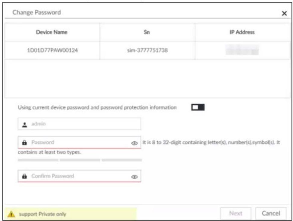
Step 3 Keep Using current device password and password protection information disabled. means that the function is disabled.
Step 4 Enter the new password, and then confirm it as required.
Step 5 Click Next button. The result of password modification is displayed.
Step 6 Click OK.
Step 7 (Optional) On the Device List page, double-click the device name, and then you can modify device name.
8.3 Network Management
Click 📍 or click + on the configuration page, select NETWORK. You can set basic network parameters and application.
Figure 8-20 Network management
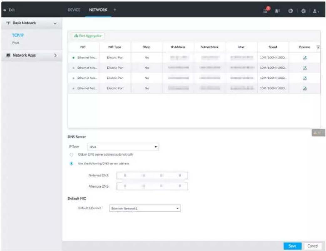
8.3.1 Basic Network
Set basic network parameters of the device, such as IP address, port aggregation and port number, to connect with other devices in the network.
8.3.1.1 Configuring IP Address
Set device IP address, DNS server information and other information according to network planning.

Device has 4 Ethernet ports by default. Make sure that at least one Ethernet port has connected to the network before you set IP address.
Step 1 Click 📍 or click + on the configuration page, and then select NETWORK > Basic Network > TCP/IP.

Click ↩ to view the NIC parameter information.
Figure 8-21 TCP/IP
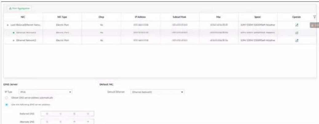
Step 2 Click √ of the corresponding NIC to edit network parameters.
Figure 8-22 Edit Ethernet network
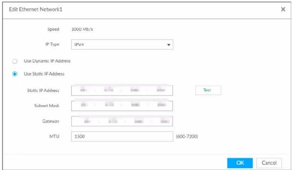
Step 3 Set parameters.
Table 8-6 TCP/IP parameters description
| Parameters | Description |
| Speed | Current NIC max network transmission speed. |
| IP Type | Select IPv4 or IPv6. |
| Use Dynamic IP Address | When there is a DHCP server on the network, check the box to use dynamic IP address, system can allocate a dynamic IP address to the device. There is no need to set IP address manually. |
| Use Static IP Address | Check the box to use static IP address. Set static IP address, subnet mask and gateway. Set a static IP address for the device. |
| Test | Test whether the IP address is valid. |
| MTU | Set NIC MTU value. The default setup is 1500 Byte.We recommend you to check the MTU value of the gateway first and then set the device MTU value equal to or smaller than the gateway value. It is to reduce the packets slightly and enhance network transmission efficiency. Please be advised that changing MTU value might result in NIC reboot, network offline and affect current running operation. Please be advised that changing MTU value might result in NIC reboot, network offline and affect current running operation. |
Step 4 Click OK.
Go back to TCP/IP page.
Step 5 Set DNS server information.
You can select to get DNS server manually or input DNS server information.

This step is compulsive if you want to use domain service.
- Check the box to auto get DNS server address, device can automatically get the DNS server IP address on the network.
- Check the box to use the following DNS server addresses, and then input primary DNS and alternate DNS IP address.
Step 6 Set default NIC.
Select default NIC from the drop-down list.

Make sure that the default NIC is online.
Step 7 Click Save.
8.3.1.2 Port Aggregation
Bind multiple NIC to create one logic NIC and use one IP address for peripheral device. The bonded NIC can work as the specified aggregation mode to work. It enhances network bandwidth and network reliability.
System supports configuring load balance, fault tolerance, and link aggregation.
Table 8-7 Aggregation mode description
| Aggregation mode | Description |
| Load balance | Device has bonded several NICs at the same time and use one IP address to communicate with the external device. The bonded NICs are working together to bear the network load.The load balance mode adds the network throughput data amount and enhances network flexibility and availability. In this mode, the network is offline once all NICs break down. |
| Fault-tolerance | In this mode, device has bonded several NICs and set one NIC as the main card and the rest NICs are the alternative NICs. Usually, only the main NIC card is working. System can automatically enable other alternate cards to work when the main card breaks down.Fault-tolerance is a network mode to enhance NIC reliability. In this mode, the network is offline once all NICs break down. |
| Link aggregation | Device has bonded several NICs and all NICs are working together to share the network load. System allocates data to each NIC according to your allocated strategy. Once the system detects that one NIC breaks down, it stops sending data with this NIC, and then system transmits the data among the rest NICs. System calculates transmission data again after malfunctioning NIC resumes work.In this mode, the network is offline once all bonded NICs are malfunctioning.Make sure that the switch supports link aggregation and you have set the link aggregation mode. |
8.3.1.2.1 Binding NIC
System supports load balance, fault-tolerance, and link aggregation. Select bind mode according to your actual requirements.
Step 1 Click 📍 or click + on the configuration page, and then select NETWORK > Basic Network > TCP/IP.
Step 2 Bind NICs.
1) Click Port Aggregation.
2) Select the NICs you want to bind.
3) Select an aggregation mode.
4) Click Port Aggregation.

The setting page varies depending on the aggregation mode you have selected. The following figure is the load balance setting page.
Figure 8-23 Edit load balance
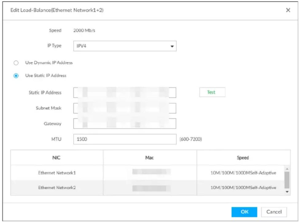
5) Set parameters.
Table 8-8 TCP/IP parameters description
| Parameters | Description |
| Speed | Maximum network transmission speed of current NIC. |
| IP Type Select IPv4 or IPv6. | |
| Use Dynamic IP Address | When there is a DHCP server on the network, check the box to use dynamic IP address. System can allocate a dynamic IP address to the device. There is no need to set IP address manually. |
| Use Static IP Address | Check the box to use static IP address. Set static IP address, subnet mask and gateway. It is to set a static IP address for the device. |
| Test | Test whether the IP address is valid. |
| MTU | Set NIC MTU value. The default setup is 1500 Byte.We recommend you to check the MTU value of the gateway first and then set the device MTU value equal to or smaller than the gateway value. It is to reduce the packets slightly and enhance network transmission efficiency. Please be advised that changing MTU value might result in NIC reboot, network offline and affect current running operation. Please be advised that changing MTU value might result in NIC reboot, network offline and affect current running operation. |
6) Click OK.
Go back to TCP/IP page.
Step 3 Click Save.
System pops up a confirmation box.
Step 4 Click OK.
The binding card information becomes activated after reboot operation.
8.3.1.2.2 Cancelling Binding NIC
Cancel port aggregation and allow the bonded NICs to work as independent card.
Step 1 Click 🎨 or click + on the configuration page, and then select NETWORK > Basic Network > TCP/IP.
Step 2 Select a bonded NIC.
Step 3 Click OK.
System splits the bonded NIC.

After splitting NIC binding, the first NIC reserves the IP address configured during binding, while the rest NICs restore default IP addresses.
8.3.1.3 Setting Port Number
Set device port number.
Step 1 Click 🎨 or click + on the configuration page, and then select NETWORK > Basic Network > Port.
Figure 8-24 Port
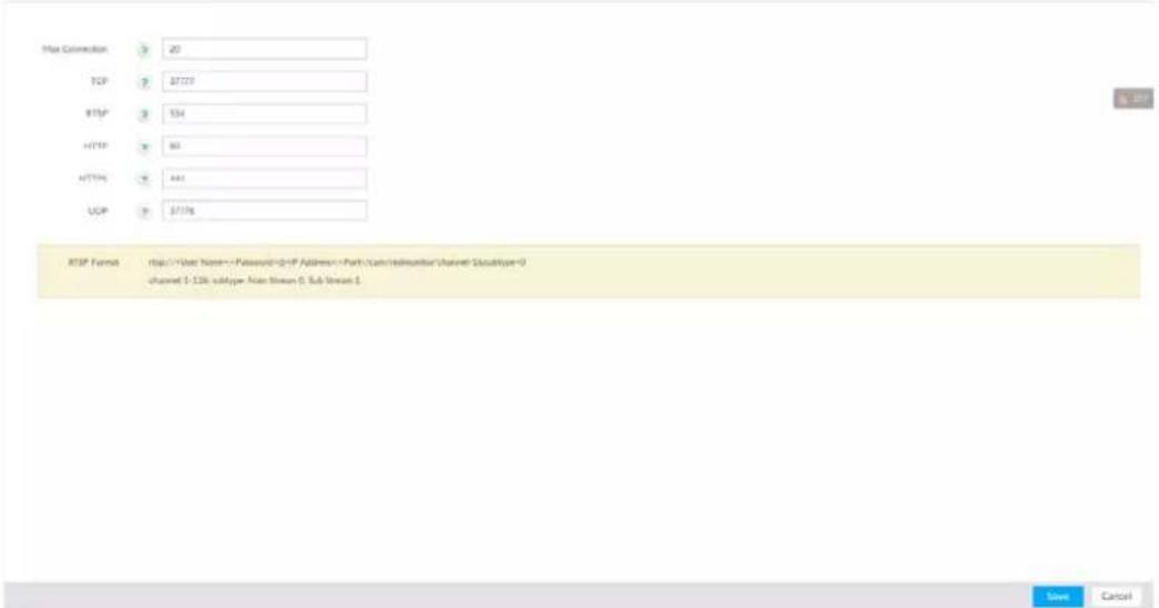
Step 2 Set parameters.

Log in again after modifying parameters except Max Connection.
Table 8-9 Connection setting parameters description
| Parameters | Description |
| Max Connection | The allowable maximum clients accessing the Device at the same time, such as web, PCAPP, and Platform. Select a value between 1 and 128. The default value setting is 20. |
| TCP Port | Set according to the actual requirements. The default value is 37777. The value ranges from 1025 to 65535. |
| RTSP Port | Set according to the actual requirements. The default value is 554. The value ranges from 1 to 65535. |
| HTTP Port | Set according to the actual requirements. The default value is 80. The value ranges from 1 to 65535.If the value you set is not 80, please add the port number after the IP address when you are using browser to login the device. |
| HTTPS Port | Set according to the actual requirements. The default value is 443. The value ranges from 1 to 65535. |
| UDP Port | Set according to the actual requirements. The default value is 37778. The value ranges from 1025 to 65535. |
Step 3 Click Save.
System reboots corresponding service of the port.
8.3.2 Network Apps
Set device network parameters, so that system can connect to other devices.
8.3.2.1 P2P
P2P is a peer to peer technology. You can scan the QR code to download cellphone APP without DDNS service or the port mapping or installing the transmission server. After register the device to the APP, you can view the remote video, playback record file and so on.

- Make sure that the system has connected to the network. Otherwise, the P2P function is null.
- When using the P2P function, we will collect device information such as IP address, MAC address, name and serial number. The collected information is only used for remote access.
Step 1 Click ⚙, or click + on the configuration page, and then select NETWORK > Network Apps > P2P.
Figure 8-25 P2P
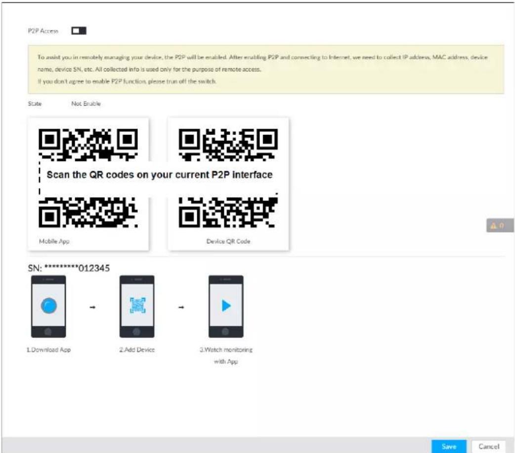
Step 2 Click □ to enable P2P function.
Step 3 Click Save.
After the configuration, you can register a device to the APP to view remote video, playback record file, and so on. See corresponding cellphone APP for detailed information.

After successfully connected to the P2P, the status displayed as Success.
8.3.2.2 DDNS
After setting DDNS parameters, when IP address of the Device changes frequently, the system dynamically updates the relation between domain name and IP address on DNS server. You can use domain name to remotely access the Device, without need to note down IP address.
8.3.2.2.1 Preparation
Confirm whether IVSS supports the DDNS Type and log in the website provided by the DDNS service provider to register the information such as domain from PC located in the WAN.

After you have registered and logged in the DDNS website successfully, you can view the information of all the connected devices under this username.
8.3.2.2.2 Procedure
Step 1 Click 📍 or click + on the configuration page, and then selectNETWORK > Basic Network > DDNS.
Figure 8-26 DDNS
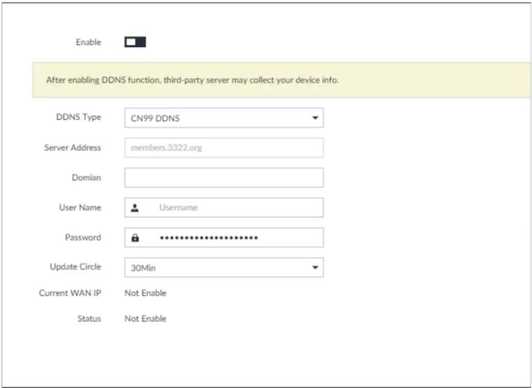
Step 2 Click □ to enable DDNS function.

After enabling DDNS function, the third-party server might collect your device information. Pay attention to privacy security.
Step 3 Set the corresponding parameters.
Table 8-10 DDNS setting parameters description
| Parameters | Description |
| DDNS Type | Name and address of DDNS service provider.Dyndns DDNS: members.dyndns.orgNO-IP DDNS: dynupdate.no-ip.comCN99 DDNS: members.3322.org |
| Server Address | Name and address of DDNS service provider.Dyndns DDNS: members.dyndns.orgNO-IP DDNS: dynupdate.no-ip.comCN99 DDNS: members.3322.org |
| Domain | The domain name for registering on the website of DDNS service provider. |
| User Name | Enter the username and password obtained from DDNS service provider.You need to register (including username and password) on the website of DDNS service provider. |
| Password | |
| Update Circle | Enter the amount of time that you want to update the DDNS. |
| Current WAN IP | Displays the WAN IP address of IVSS. |
| Status | Displays DDNS registration result or update status. |
Step 4 Click Save.
After successful configuration, enter domain name in address bar of the browser or PCAPP, and press Enter key to access the IVSS.
8.3.2.3 Email
Configure email information, and enable alarm linked email. When NVR has alarm events, the system automatically sends emails to the user.

Device data will be sent to specific servers after the email function is enabled. Be cautious.
Step 1 Click 🎨, or click + on the configuration page, and then select NETWORK > Network Apps > Email.
Figure 8-27 Configuring Email
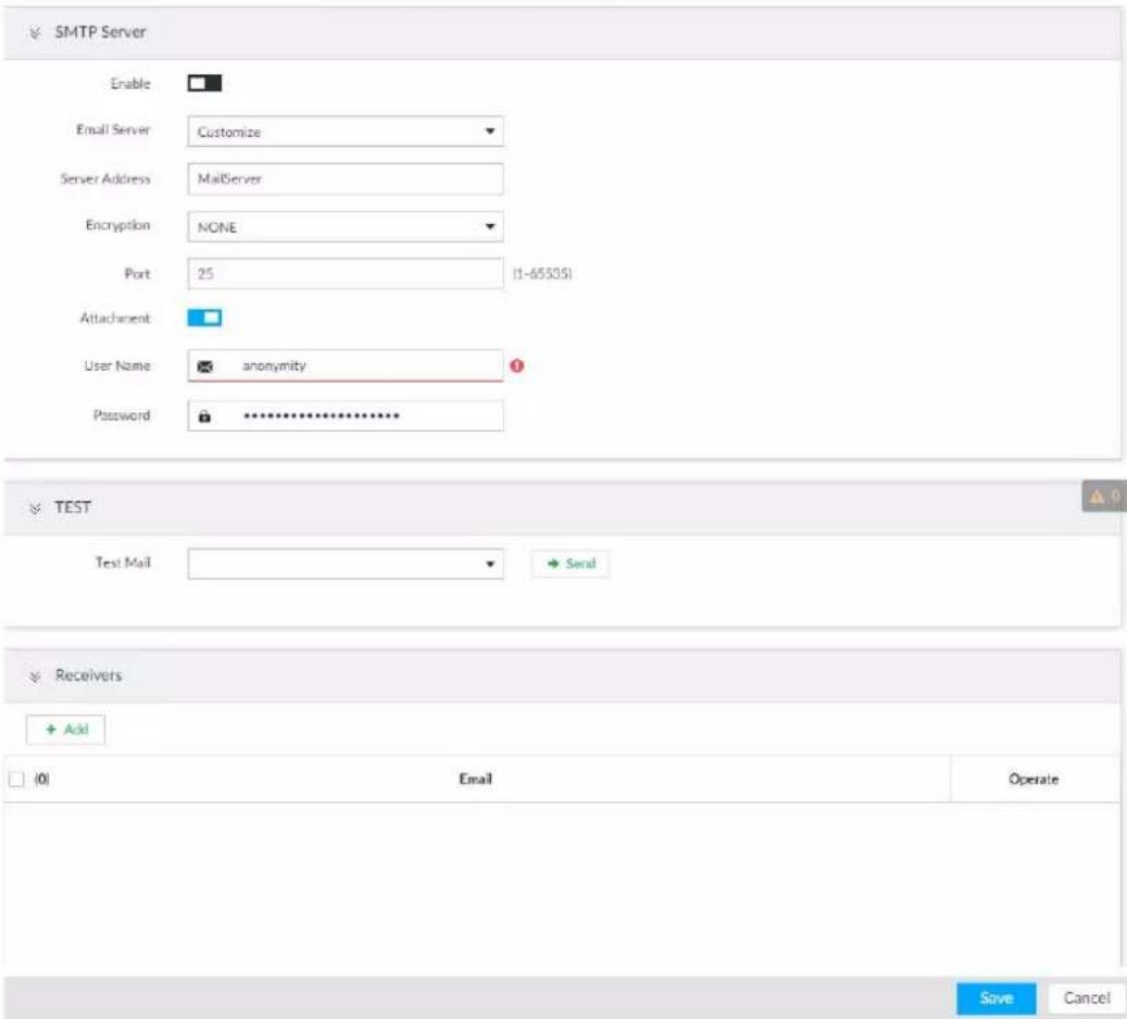
Step 2 Click □ to enable the email function.
Step 3 Set parameters.
Table 8-11 EMAIL parameter description
| Parameters | Description |
| Email Server | Select email server type, including Customize, Gmail, Hotmail, and Yahoo. |
| Server Address | Enter email server address. |
| Encryption | Set the encryption type of email server, such as NONE, SSL, and TLS.You are recommended to select TLS. Other encryption methods might not be safe. |
| Port | Enter the port number of email server. |
| Username and password | Enter the configured username and password of Email server. |
Step 4 Add the information of mail receiver.
1) Click Add.
2) Enter a receiver email address.
3) Click Add or + to add other receiver email address.
- Click 📋 to delete the added receiver.
- Select a receiver. The Delete button is displayed. Click Delete button to delete the selected receiver.
Step 5 Click Save.
Step 6 (Optional) Test the email sending function.
1) In Test Mail, select or enter a receiver email address.
2) Click Send.
- When the configuration is correct, the system pops up a message of success, and the receiver will receive the test mail.
- Otherwise, the system pops up a message of failure, and the receiver will not receive the test mail.
8.3.2.4 SNMP
After setting SNMP (Simple Network Management Protocol) and successfully connecting devices through relevant software tools such as MIB Builder, and MG-SOFT MIB Browser, you can directly manage and monitor devices on software tools.

- Install SNMP device monitoring and management tools, such as MIB Builder and MG-SOFT MIB Browser.
- Obtain the MIB file corresponding to the current version from technical support.
Step 1 Click ⚙, or click + on the configuration page, and then select NETWORK > Network Apps > SNMP.
Figure 8-28 SNMP (1)
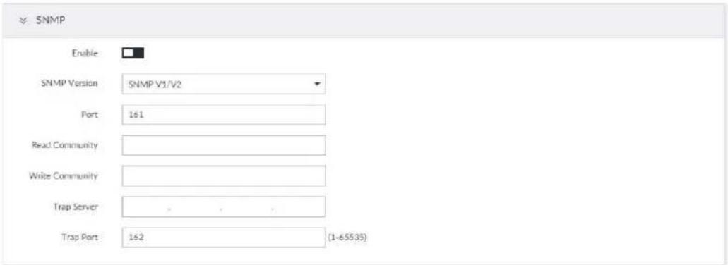

Step 2 Click □ to enable the function.
Step 3 Select SNMP version.
- If you have selected SNMP V1/V2, see the previous figure.
- If you have selected SNMP V3, see the following figure.
Figure 8-29 SNMP(2)
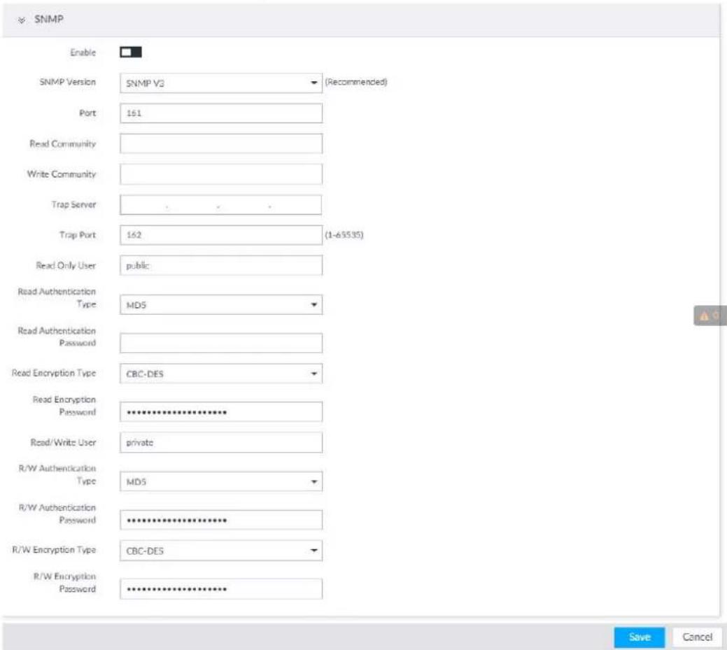
Step 4 Set parameters. For Trap server address, enter the IP address of the PC that has MG-SOFT MIB Browser. Keep the other parameters as default.
Table 8-12 SNMP parameters
| Parameters | Description |
| Port | Listening port of agent programs on the device. |
| Read Community, Write Community | Read or Write Community supported by the agent programs. The name can only contain numbers, letters, underscores, and middle lines. The name can only contain numbers, letters, underscores, and middle lines. |
| Trap Server | The destination address of Trap information sent by the agent program. |
| Trap Port | The destination port of Trap information sent by the agent program. |
| Read Only User | Set the username the read-only user. The read-only user can only have the read-only permission. The name can only contain numbers, letters, and underscores. The name can only contain numbers, letters, and underscores. |
| Read Authentication Type | You can select MD5 or SHA. It is MD5 by default. |
| Read Authentication Password | The password must contain at least 8 digits. |
| Read Encryption Type | CFB-AES by default. |
| Read Encryption Password | The password must contain at least 8 digits. |
| Read/Write User | The username is private by default. If you log in using this username, you have the read-and-write permission. The name can only contain numbers, letters, and underscores. The name can only contain numbers, letters, and underscores. |
| R/W Authentication Type | You can select MD5 or SHA. It is MD5 by default. |
| R/W Authentication Password | The password must contain at least 8 digits. |
| R/W Encryption Type CFB-AES by default. | |
| R/W Encryption Password | The password must contain at least 8 digits. |
Step 5 Click Save.
8.3.2.5 Register
Register the device on designated proxy server, and client software visits the device through the proxy server.
Step 1 Click ⚙, or click + on the configuration page, and then select NETWORK > Network Apps > Register.
Figure 8-30 Register
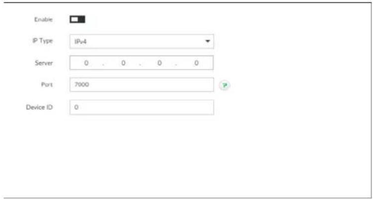
Step 2 Click □ to enable the function.
Step 3 Set parameters.
Table 8-13 Register
| Parameters | Description |
| IP Type | Select IP address of server for registration. |
| Server | In the Server box, enter the IP address of server for registration. |
| Port | Enter the port number of the server for registration. |
| Device ID | Enter Device ID to identify IVSS uniquely. Device ID shall be consistent with server configuration. |
Step 4 Click Save.
8.3.2.6 UPnP
Through the UPnP (Universal Plug and Play) protocol, you can establish a mapping relationship between the LAN and the WAN, the WAN user can use the WAN IP address to directly access the Device in the LAN.

Device services and ports will be mapped to the public network after UPnP is enabled. Be cautious.

- Make sure that your PC has UPnP network services installed.
- Log in to the router and set the WAN port IP address of router.
- Enables the UPnP function on the router.
- Connect the Device to the router LAN (Local Area Network, LAN) port.
- Select NETWORK > Basic Network > TCP/IP, and then set the IP address to be the private-network IP of the router, or select DHCP to automatically obtain the IP address.
Step 1 Click 🎨, or click + on the configuration page, and then select NETWORK > Network Apps > UPnP.
Figure 8-31 UPnP
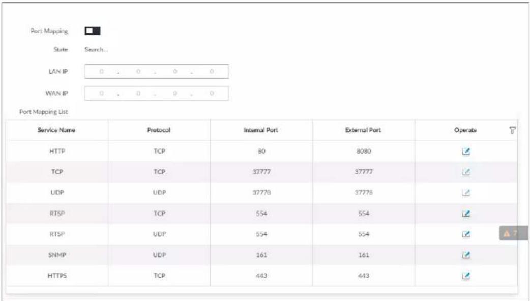
Step 2 Set parameters.
Table 8-14 UPnP parameters
| Parameters | Description |
| Port Mapping | Click □ to enable UPnP. |
| State The status of port mapping. | |
| LAN IP | The LAN IP address of the router. The IP address is automatically obtained after the mapping succeeds. The IP address is automatically obtained after the mapping succeeds. |
| WAN IP | The WAN IP address of router.[V7YY]The IP address is automatically obtained after the mapping succeeds. |
| Port Mapping List | The list is consistent with the UPnP port mapping list on the router.• Internal Port: The IVSS port to be mapped on the router.• External Port: The WAN port of the internal port.[3KYS]• When setting the external port, use the ports between 1024 and 5000, and do not use the well-known ports 1 to 255 and the system ports 256 to 1023, so as to avoid conflicts.• When there are multiple devices within the LAN, properly plan the port mapping to avoid conflicts of WAN ports.• When making a port mapping, make sure that the port you are mapping is not occupied or restricted.• The TCP/UDP WAN and LAN ports must be consistent and cannot be modified. |
| Modification | Click , and then you can modify the external port. |
Step 3 Click Save.
Enter http://WAN IP: WAN port number in the browser to access the Device with the
corresponding port number in the router network.
8.3.2.7 Multicast
When multiple users are viewing live video of the same device at the same time, it might cause failure due to limited bandwidth. To solve this problem, you can set a multicast IP address (224.0.0.0-239.255.255.255) for the Device.
Step 1 Click ⚙, or click + on the configuration page, and then select NETWORK > Network Apps > Multicast.
Figure 8-32 Multicast
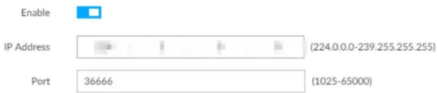
bar
| Category | Value | | ---------- | ----------- | | IP Address | 224.0.0.0-239.255.255.255 | | Port | 36666 |Step 2 Click □ to enable multicast.
Step 3 Set parameters.
Table 8-15 Parameters
| Parameters | Description |
| IP Address | Set the multicast IP address of the device (224.0.1.0–239.255.255.255). |
| Port | Set the multicast port (1025–65000). |
Step 4 Click Save.
After configuring the multicast address and port, you can log in to the web or PCAPP client through the multicast protocol.
Take PCAPP for example. On the login page of PCAPP, select Multicast as the login type.
PCAPP client will automatically obtain the multicast address and join the multicast group.
After login, you can view live videos through multicast protocol.
Figure 8-33 Log in through multicast
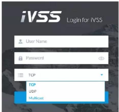
8.3.2.8 Alarm Center
You can configure the alarm center server to receive the uploaded alarm information.

Make sure that alarm center server is deployed.
Step 1 Click ⚙, or click + on the configuration page, and then select NETWORK > Network Apps > Alarm Center.
Figure 8-34 Alarm center
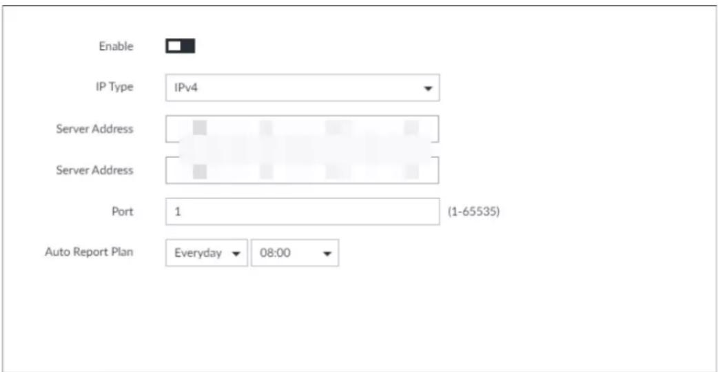
Step 2 Click □ to enable alarm center.
Step 3 Configure the parameters.
Table 8-16 Alarm center parameters
| Parameter | Description |
| IP Type | Select the IP type of the alarm center server. |
| Server Address | The IP address and communication port of the alarm center server. |
| Port | |
| Auto Report Plan | Select time cycle and specific time for uploading alarm. |
Step 4 Click Save.
8.3.2.9 Route Table
Configure the route table so that the system can automatically calculate the best path for data transmission.
Step 1 Click 🎨, or click + on the configuration page, and then select NETWORK > Network Apps > Route Table.
Step 2 Click Add.
Figure 8-35 Add route table
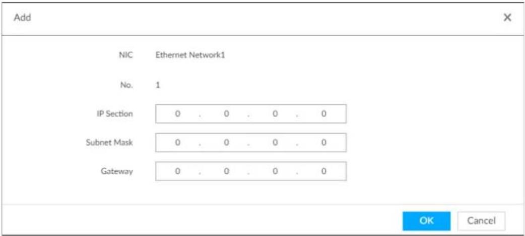
Step 3 Enter the information.
Step 4 Click OK.
8.4 Event Management
Click 🎨 or click + on the configuration page, select EVENT.
On the page, configure alarm event, including alarm event of the Device and remote device.
- Select the root node in the resource tree on the left to set alarm event of the Device.
- Select remote device in the device tree on the left, to set alarm event of this remote device.

- The alarm event might be different depending on the model you purchased.
- means that the corresponding alarm event has been enabled.
- means that AI by camera has been enabled; - means that AI by device has been enabled;
means that both have been enabled.
Figure 8-36 Event management
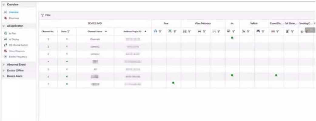
8.4.1 Alarm Actions
System can trigger the corresponding actions when an alarm occurs.

The supported actions might be different depending on the model you purchased.
On the alarm configuration page, click Actions to display actions. Configure actions according to your actual need.
- After setting actions, click Save on the page.
• After enabling actions, click × to disable the corresponding actions.
Table 8-17 Actions description
| Actions | Description | Preparation |
| Record | The system links the selected remote device to record when there is a corresponding alarm event. | Remote device, such as IPC, has been added. See "5.4.2 Adding Remote Device" for detailed information. |
| Buzzer | The system activates a buzzer alarm when there is a corresponding alarm event. | - |
| Log | The system notes down the alarm information in the log when there is a corresponding alarm event. | |
| The system sends alarm email to all added receivers when there is corresponding an alarm event. | Email configuration has been completed. See "8.3.2.3 Email" for detailed information. | |
| Snapshot | The system takes snapshots of the linked channel when there is an alarm event. | - |
| Preset | The system links the selected remote device to rotate to the designated preset point when there is a corresponding alarm event. | PTZ device has been added, and preset point has been added. See "5.4.2 Adding Remote Device" for detailed information. |
| Local Alarm Output | When there is an alarm, system can trigger the corresponding device to generate alarm. | The Device is connected with alarm output device. See "3.4.1.4 Alarm Output". |
| Remote Device Alarm Output | The remote device has been added, and the remote device is connected with alarm output device. See "5.4.2 Adding Remote Device" for detailed information. | |
| Access | When there is an alarm, system can trigger the corresponding access control device to open door and close door. | See "5.4.2 Adding Remote Device" for detailed information. |
| Voice Prompt | When there is an alarm, system can play the selected audio file. | Audio function has been configured. See "7.3.5 Voice Management" for detailed information. |
| Smart Tracking | Alarm is triggered when a tripwire or intrusion behavior is detected. If smart tracking action is configured, the PTZ camera automatically rotates to the target view to track it. | See "7.1.1.3.6 Smart Tracking". |
| Report Alarm | When an alarm occurs, the system reports the alarm to alarm center. | Alarm center has been enabled. For details, see "8.3.2.8 Alarm Center". |
| Audio and Light Alarm | When an alarm occurs, the system associates with the remote device to perform audio and light actions. | The camera that supports this function has been connected. For details, see "8.4.1.13 Audio and Light Alarm". |
8.4.1.1 Record
Enable record control function. The system links the selected remote device to record when there is corresponding alarm event.

Make sure that the remote device, such as IPC, has been added. See "5.4.2 Adding Remote Device" for detailed information.
Step 1 Click Actions, and then select Record.
Figure 8-37 Record

Step 2 Set the time length of recording after the event moment.
Step 3 (Optional) Repeat Step 1–Step 2 to link multiple remote devices to record.
8.4.1.2 Buzzer
The system activates a buzzer alarm when there is corresponding alarm event.
Click Actions and select Buzzer to enable this function.
Figure 8-38 Buzzer

8.4.1.3 Log
Enable the log function. The system notes down the alarm information in the log when there is corresponding alarm event.
Click Actions and select Log to enable this function.
Figure 8-39 Log


When log function is enabled, after an alarm is triggered, click + on LIVE page, select MAINTAIN > Log > Event.
8.4.1.4 Email
Enable Email function. The system sends alarm email to all added receivers when there is corresponding alarm event.

Make sure that the email configuration has been completed. See "8.3.2.3 Email" for detailed information.
Click Actions and select Email to enable this function.
Figure 8-40 Email

8.4.1.5 Preset
Set preset function. The system links the selected remote device to rotate to the designated preset point when there is corresponding alarm event.

Make sure that the PTZ device has been added, and preset has been added. See "5.4.2 Adding Remote Device" for detailed information.
Step 1 Click Actions and select Preset.
Figure 8-41 Preset

Step 2 Select PTZ device, and enter preset number.
Step 3 (Optional) Repeat Step 1–Step 2, and link multiple PTZ devices to turn to designated presets.
8.4.1.6 Snapshot
Set the snapshot linkage action for alarms, so that once an alarm happens, it will trigger a snapshot of the alarm.
Click Actions, and then select Snapshot.
Figure 8-42 Snapshot action

8.4.1.7 Local Alarm Out
Set local alarm output. System can trigger the corresponding alarm event when an alarm occurs.

Make sure that the Device is connected with alarm output device.
Step 1 Click Actions and select Local Alarm Out.
Figure 8-43 Local alarm out

Step 2 Select alarm output port.
You can select multiple alarm output ports.
Step 3 Set delay time.
Set a delay time. After alarm event is ended, alarm will end after the delay time. You can configure from 0 seconds through 300 seconds, and the default value is 10 seconds.
8.4.1.8 Remote Device Alarm Output
Set remote device alarm output. The system can link the corresponding alarm output device to output alarm when an alarm occurs.

Make sure that the remote device has been added, and the remote device is connected with alarm output device. See "5.4.2 Adding Remote Device" for detailed information.
Step 1 Click Actions and select Remote Device Alarm Output.
Figure 8-44 Remote device alarm output settings
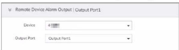
Step 2 Select a remote device and alarm output port.
You can select multiple alarm output ports.
Step 3 (Optional) Repeat Step 1–Step 2, and link multiple remote alarm output devices.
8.4.1.9 Access
Set access control function. When there is an alarm, system can trigger the corresponding access control device to open door and close door.

Make sure that access control device has been added. See "5.4.2 Adding Remote Device" for detailed information.
Step 1 Click Actions and select Access.
Figure 8-45 Access

Step 2 Select access control device.

Not all models support this function.
Step 3 (Optional) Repeat Step 1–Step 2, and link multiple access control devices.
8.4.1.10 Voice Prompt
Set voice prompt function. When there is an alarm, system can play the selected audio file.

Make sure that the voice function has been configured. For details, see "7.3.5 Voice Management". Step 1 Click Actions and select Voice Prompt.
Figure 8-46 Voice prompt

Step 2 In the File Name list, select the audio file that you want to play for this configured period. Step 3 Set delay time.
- Play times: Select Play Times and enter the times to play the file. After the alarm event is ended, system will continue to play the voice file according to the play times.
- Duration: Select Duration and enter the delayed play duration. After the alarm event is ended, system will continue to play the voice file according to the duration.
8.4.1.11 Smart Tracking
Alarm is triggered when a tripwire or intrusion behavior is detected. If smart tracking action is configured, the PTZ camera automatically rotates to the target view to track it.

- Smart tracking is only available for AI by camera.
- Smart tracking is only available on the multi-sensor panoramic camera + PTZ camera.
On the event configuration page, select Actions > Smart Tracking to enable the action.
8.4.1.12 Report Alarm
Click Actions and then select Report Alarm to enable this function. Where there is an alarm, the system reports the alarm to alarm center.

Make sure that alarm center has been enabled. For details, see "8.3.2.8 Alarm Center".
8.4.1.13 Audio and Light Alarm
Set audio and light alarm for IVS detection. When there is an alarm, the system associates with the remote device to perform audio and light actions.

Audio and light alarm is available when AI by camera is used for IVS detection and the camera supports this function.
Step 1 Click Actions and select Camera Audio and Remote Warning Light.
Figure 8-47 Camera audio
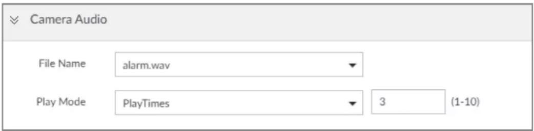
Figure 8-48 Remote warning light
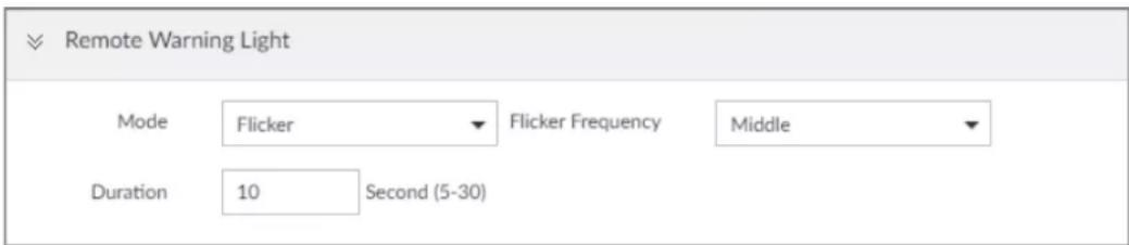
Step 2 Configure the parameters.
Table 8-18 Audio and light alarm parameters
| Parameter | Description | |
| Camera Audio | File Name | Select the audio file to be played when an alarm is triggered. |
| Play Mode | Set the play times of audio file. | |
| Remote Warning Light | Mode Select | Flicker or Always on. |
| Flicker Frequency | When Flicker is selected as Mode, set the flicker frequency. | |
| Duration | Set how long the warning light flickers or keeps on after an alarm is triggered. | |
8.4.2 Local Device
Set IVSS alarm event, including abnormal event, device offline alarm, AI application, and local device alarm.
8.4.2.1 One-click Disarming
Disarm alarm linkage actions as needed to avoid interference caused by alarms.
Step 1 Click 🎨, or click + on the configuration page, and then select EVENT.
Step 2 Select the root node in the device tree.
Step 3 Select Overview > Disarming.
Figure 8-49 Disarming
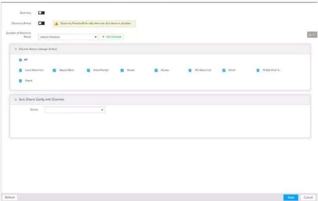
Step 4 Click □ to enable disarming.
Step 5 Cancel selecting alarm linkage actions as needed. The actions are selected by default.
Step 6 (Optional) Configure disarming by period.
1) Click □ to enable disarming by period.
2) Click Add Schedule to specify disarming schedule. The alarm linkage actions remain armed during unscheduled periods.
3) Click Apply.

After disarming by period is enabled, one-click disarming is disabled automatically.
Step 7 Configure sync disarming configuration with channels.
1) Click the drop-down list in the Sync Disarm Config with Channels section. The devices that support one-click disarming or disarming by period are displayed.
2) Select the device that you want to synchronize the disarming configuration with.
Step 8 Click Save.
8.4.2.2 Abnormal Event
Set the alarm mode when an abnormal event occurs.
The Device supports HDD, storage error, network, AI module, fan and power fault alarm.
Table 8-19 Abnormal event description
| Name | Description |
| No HDD | System triggers an alarm when there is no HDD. It is enabled by default. |
| Storage error | System triggers an alarm in case of HDD error. It is enabled by default. |
| Storage full | System triggers an alarm when the used storage space reaches the pre-defined threshold. It is disabled by default. The alarm is valid only when the storage mode is set asStop on the STORAGE >VIDEO RECORDING >Basic page. The alarm is valid only when the storage mode is set asStop on the STORAGE >VIDEO RECORDING >Basic page. |
| RAID exception | System triggers an alarm in case of RAID degrade, RAID broken or other RAID exceptions. |
| IP conflict | System triggers an alarm when its IP address conflicts with IP address of other device in the same LAN. It is enabled by default. |
| MAC conflict | System triggers an alarm when its MAC address conflicts with MAC address of other device in the same LAN. It is enabled by default. |
| Lock in | System triggers an alarm when an account login error has reached the threshold. At the same time, system locks current account. It is disabled by default. Go to the Security page to set account error threshold. See "8.6.3 Safety Protection" for detailed information. Go to the Security page to set account error threshold. See "8.6.3 Safety Protection" for detailed information. |
| AI module temp | When AI module temperature is higher than the specified value, system triggers an alarm. It is enabled by default. |
| AI module offline | When AI module and system is disconnected, system triggers an alarm. It is enabled by default. |
| Fan speed alarm | When fan speed is abnormal, system triggers an alarm. It is enabled by default. |
| Power fault | When power supply is abnormal, system triggers an alarm. It is disabled by default. |
Here we take AI module temp for example. For other events, the setting steps are similar. See the actual page for detailed information.
Step 1 Click 🎨, or click + on the configuration page, and then select EVENT.
Step 2 Select the root node in the device tree.
Step 3 Select Abnormal Event > AI Module TEMP.
Figure 8-50 AI module temp
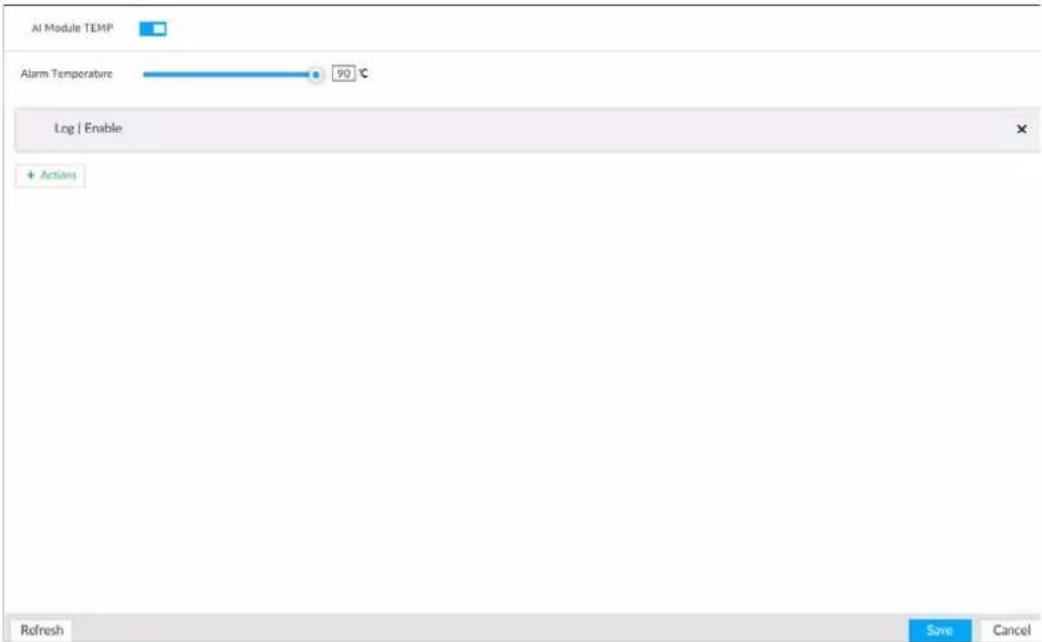
Step 4 Click □ to enable AI module temperature alarm function.
Step 5 Drag to set alarm temperature threshold.

The above step is for AI module temperature alarm only.
Step 6 Click Actions to set alarm actions. See "8.4.1 Alarm Actions" for detailed information.
Step 7 Click Save.
8.4.2.3 Offline Alarm
Set IVSS network offline alarm. If you have not set offline alarm for a specified remote device, once the remote device is disconnected from the system, system adopts IVSS alarm strategy to trigger an alarm.
Step 1 Click 🎨, or click + on the configuration page, and then select EVENT.
Step 2 Select the root node in the device tree on the left.
Step 3 Select Device Offline > Device Offline.
Figure 8-51 Offline alarm
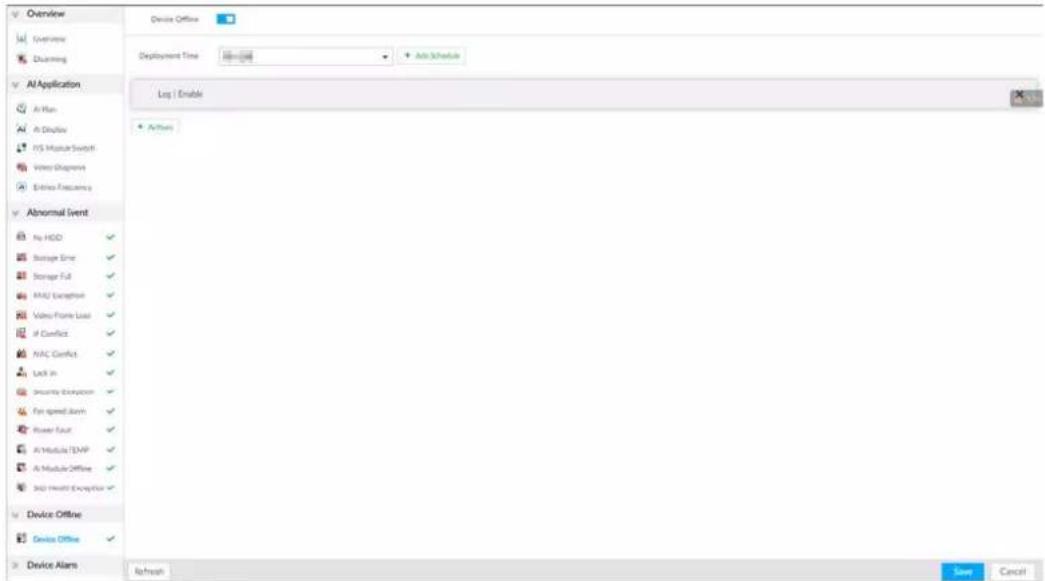
Step 4 Click □ to enable device offline alarm.
Step 5 Click Deployment Time to select schedule from the drop-down list.
After setting deployment period, system triggers corresponding operations when there is a motion detection alarm in the specified period.
- Click View Schedule to view detailed schedule settings.
- If the schedule is not added or the added schedule does not meet actual needs, click Add Schedule. See "8.8.4 Schedule" for detailed information.
Step 6 Click Actions to set alarm actions. See "8.4.1 Alarm Actions" for detailed information.
Step 7 Click Save.
8.4.2.4 Configuring AI Application
Configure AI detection result display strategy of the Device. If you have not set AI display settings for current remote device, the remote device inherits AI display mode of the Device.
8.4.2.4.1 Viewing AI Plan
After adding remote device, on IVSS, obtain AI detection type and status of the remote device.
On the EVENT page, select the root node in the device tree on the left. Select AI Application > AI Plan > AI Plan.
After installing the AI module, and the remote device supports AI detection, and you have enabled the AI detection function, you can view channel name of the remote device on the corresponding AI detection panel.

indicates that AI by camera is enabled; indicates that AI by device is enabled.
Figure 8-52 AI plan
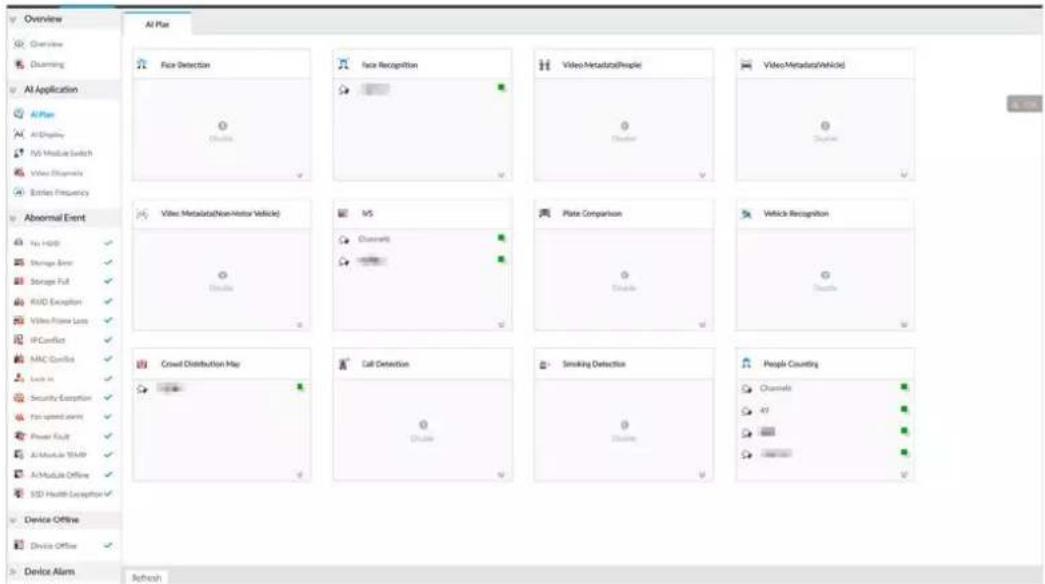
8.4.2.4.2 Setting AI Display
Set the property to be displayed in rule box and feature property panel. View AI detection result through smart preview, and support to display face, human and vehicle.

Take the procedure of configuring face detection AI display as an example. For other AI detection functions, the procedures are similar.
Step 1 Click 🎨, or click + on the configuration page, and then select EVENT.
Step 2 Select the root node in the device tree on the left.
Step 3 Select AI Application > AI Display > Face.
Figure 8-53 Face
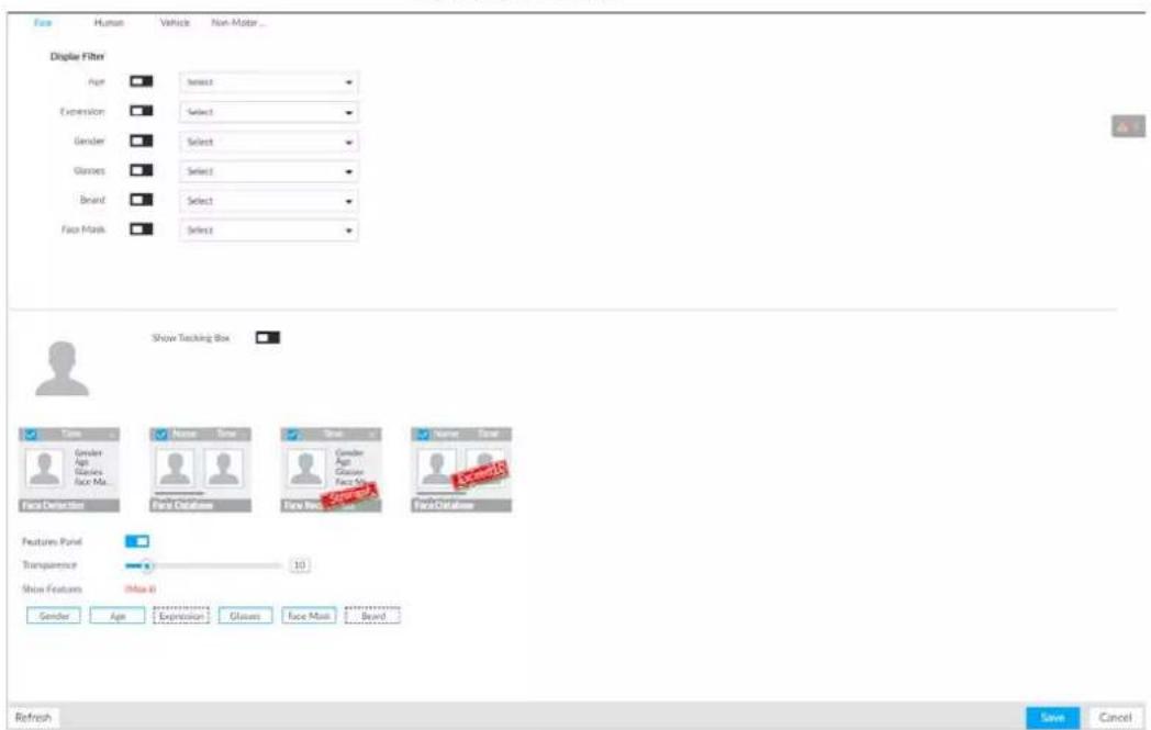
Step 4 Configure display filter information.
After setting filter criteria, only the qualified detection result will be displayed. For example, enable Age, and then select youth from the drop-down list. The tracking box and the features panel only display the human face of the youth age.
1) Click □ to enable corresponding filter type.
2) Set display filter criteria. Click ♦, to set the filter color.
Step 5 Click □ in the right of Show Tracking Box to enable.
After enabled, when the system detects face or human, tracking box will be shown beside the face or human in the view window.
Figure 8-54 Tracking box
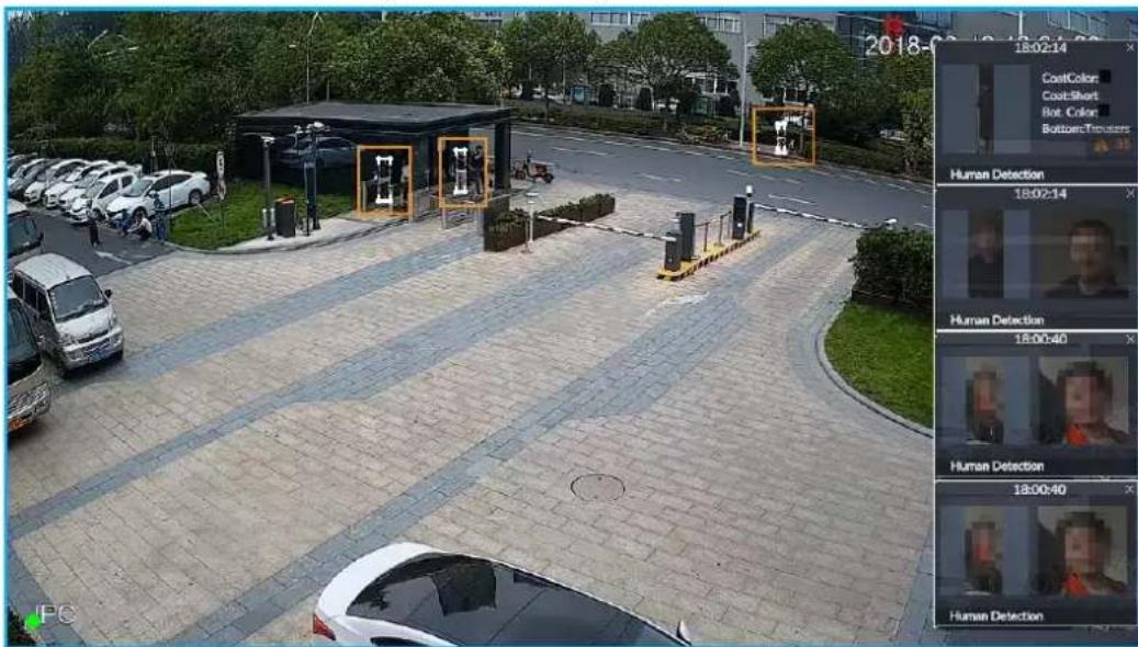
Step 6 Click □ in the right of Features Panel to enable, and select the features to be displayed on the LIVE page.
After enabled, there is a features panel on the right side of the view window.
- Drag ☐ to adjust features panel transparency. The higher the value, the more transparent the features panel.
- System supports maximum 4 features. System has checked four features by default. To select other features, cancel the selected features, and then select the ones you need.
- Click √ to display the features panel on the LIVE page, including face detection panel, stranger panel and face DB panel.
Figure 8-55 Features panel
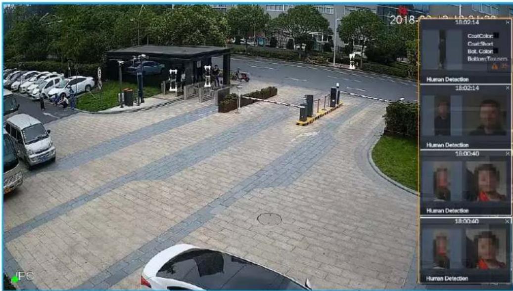
Step 7 Click Save.
8.4.2.4.3 Setting Entries Frequency
Step 1 Click 🎨, or click + on the configuration page, and then select EVENT.
Step 2 Select the root node in the device tree on the left.
Step 3 Select AI Application > Entries Frequency.
Figure 8-56 Entries frequency
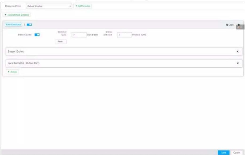
Step 4 Click Associate Face Database, and then select the database to be linked.
Step 5 Configure the parameters.
Table 8-20 Entries frequency parameters
| Parameter | Description |
| Entries Counter | Click ☐ to enable entries counter. Entries will be counted. |
| Statistical Cycle | Set the statistical cycle as needed.The statistical cycle is 7 days by default. |
| Entries Detected | Set the threshold of entries frequency as needed. When the entries detected reaches or exceeds the threshold, an alarm is triggered.The value is 1 by default. |
| Reset Clear all entry counts. | |
Step 6 Click the Deployment Time drop-down list to select or add a schedule as needed. After setting the deployment time, only an alarm occurring within the schedule triggers linkage actions.
Step 7 Click Actions to set alarm linkage actions.
Step 8 Click Save.
After setting entries frequency, when the entries detected of a person reach or exceed the threshold, the features panel on the right side of the view window displays a high frequency tag. You can find the tag using live view or AI search.
- For details about live view, see "6.2.3 Live View of Face Detection".
- For details about face search, see "6.2.4 Face Search".
Figure 8-57 High frequency tag
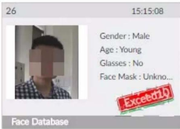
8.4.2.4.4 Video Diagnosis
The Device can analyze and trigger alarm against blurry image, tampering, color cast and more, and then generate statistics reports.
Configuring Video Diagnosis
After enabling video diagnosis, the Device triggers an alarm when the video quality is affected by blurry image, tampering, color cast and more.
Step 1 Log in to PCAPP.
Step 2 Click 🎨, or click + on the configuration page, and then select EVENT.
Step 3 Select the root node in the device tree on the left.
Step 4 Select AI Application > Video Diagnosis.
Figure 8-58 Video diagnosis
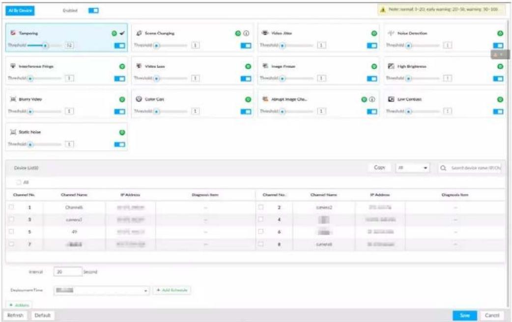
Step 5 Click □ to enable video quality analysis.
Step 6 Configure the parameters
1) Click □ to enable a type of video quality analysis, for example, tampering.
2) Set the threshold.
3) On the device list, select one or more devices.
4) Set the interval.
Step 7 Click the Deployment Time drop-down list to select a schedule.
After setting the deployment time, only an alarm occurring within the schedule triggers linkage actions.

If no schedule is added or the added schedule does not meet actual needs, click Add Schedule.
Step 8 Click Actions to set alarm linkage actions.
Step 9 Click Save.
Viewing AI Report
You can view the daily, monthly, or yearly video diagnosis statistics report of specific devices.
Step 1 On the Live page, click +, and then select AI Report > Video Diagnosis.
Step 2 Select a device and diagnosis type.
Step 3 Select Daily, Monthly, Yearly and then set a specific date, month or year.
Step 4 Click OK.
The diagnosis statistics are displayed in a statistical chart. You can view the channel name and diagnosis time on the list below the chart.

- Click 📂 to display the statistics in a bar chart.
- Click to display the statistics in a pie chart.
Figure 8-59 AI report
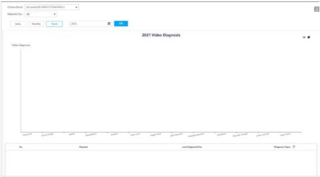
8.4.2.5 Configuring Device Alarm
Set device alarm. When alarm input device sends an alarm signal to the Device, an alarm is triggered.

- Make sure that the Device is connected with alarm input device.
- The Device supports 16-channel alarm input. Configure according to actual port of alarm input device. Take ALARM1 port connection for example.
Step 1 Click 🎨 or click + on the configuration page, and then select EVENT.
Step 2 Select the root node in the device tree on the left.
Step 3 Select Device Alarm > IO1.
Figure 8-60 IO1
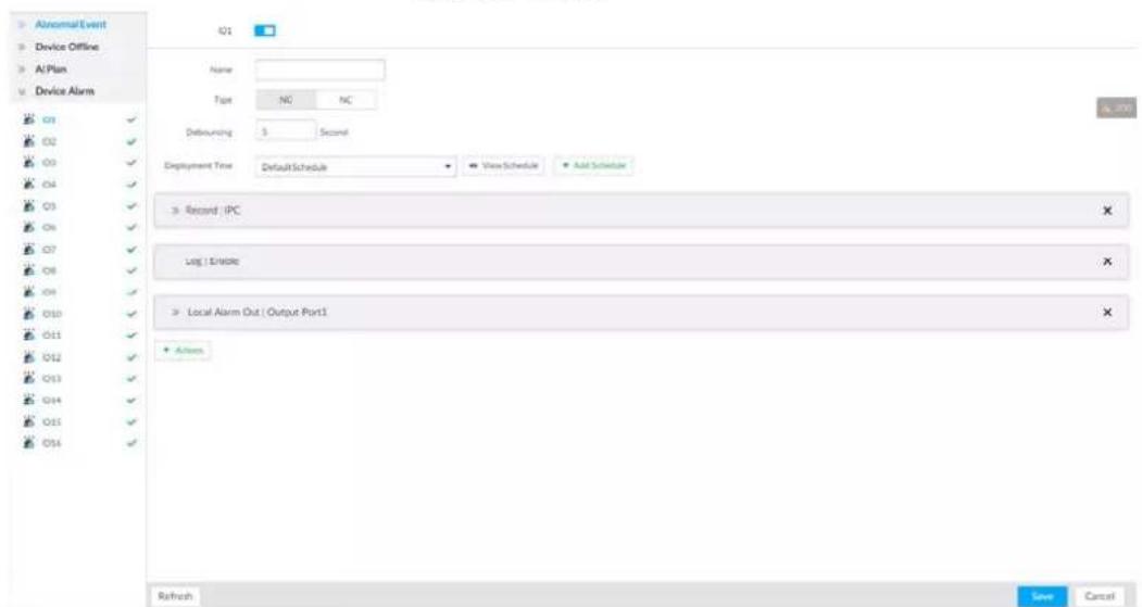
Step 4 Click □ to enable local alarm.
Step 5 Set parameters.
Table 8-21 Local alarm parameters description
| Parameters | Description |
| Name In the Alarm name box, enter a name for the alarm. | |
| Type | Select alarm input device type. Both NO and NC are supported. |
| Debouncing | The system records only one event during this period. |
Step 6 Click Deployment Time to select schedule from the drop-down list.
After setting deployment period, system triggers corresponding operations when there is a motion detection alarm in the specified period.
- Click View Schedule to view detailed schedule settings.
- If the schedule is not added or the added schedule does not meet actual needs, click Add Schedule. See "8.8.4 Schedule" for detailed information.
Step 7 Click Actions to set alarm actions. See "8.4.1 Alarm Actions" for detailed information.
Step 8 Click Save.
8.4.3 Remote Device
Set alarm actions of remote device, including video detection alarm, offline alarm and AI plan of remote device.

The parameters might be different depending on the model you purchased.
8.4.3.1 Video Detection
Video detection function adopts the PC visual, image and graphical processing technology to analyze the video image and check there is considerable changes on the video. Once there are considerable video changes (such as there is any moving object, or the video is blurred), system triggers corresponding alarm event.
8.4.3.1.1 Configuring Video Motion
After analyzing video, system can generate a video motion alarm when the detected moving target reaches the sensitivity you set here.
Step 1 Click 🎨, or click + on the configuration page, and then select EVENT.
Step 2 Select remote device in the device tree on the left.
Step 3 Select Video Detect > Video Motion.
Figure 8-61 Video motion
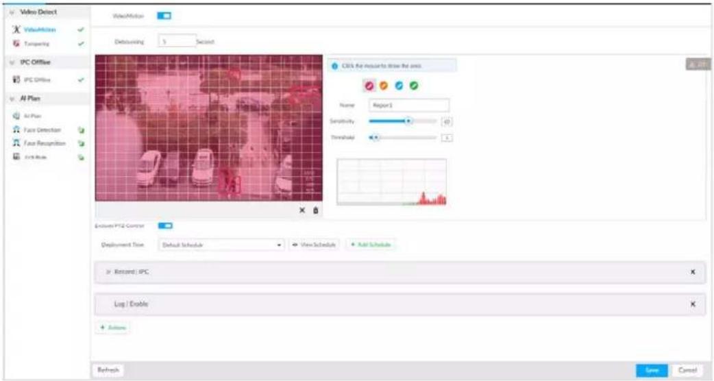
Step 4 Click □ to enable video motion detection.
Step 5 Set parameters.
Table 8-22 Motion detect parameters description
| Parameters | Description |
| Debouncing | System only records one alarm event during the debouncing period. |
| Exclude PTZ control | After enabling exclude PTZ control, system does not trigger an alarm when you are manually control the PTZ. It is for PTZ camera only. It is for PTZ camera only. |
Step 6 Set motion detection region.
System supports maximum four detection zones. After setting, once there is an alarm from any of these four zones, the remote device triggers an alarm.
1) Click motion detection zone icon
2) On the surveillance video, press and hold on the left button of mouse to select detection zone.
- Select the motion detect zone you have drawn. Click × to delete the zone.
- Click 📁 to clear the zone you have drawn.
3) Set parameters.
Table 8-23 Description of zone parameters
| Parameters | Description |
| Name | Set detection zone name to distinguish different zones. |
| Sensitivity | Drag to set sensitivity.The higher the sensitivity is, the easier it is to trigger an alarm. At the same time, the false alarm rate increases as well. Usually we recommend the default value. |
| Threshold | Drag to adjust threshold.Once the detected percentage (the percentage of target to detection zone) is equivalent to or larger than the specified threshold, system triggers alarm. For example, the threshold is 10. Once the detected target occupies the 10% of the detection zone, system triggers an alarm. |
Step 7 Click Deployment Time to select schedule from the drop-down list.
After setting deployment period, system triggers corresponding operations when there is a motion detection alarm in the specified period.
- Click View Schedule to view detailed schedule settings.
- If the schedule is not added or the added schedule does not meet actual needs, click Add Schedule. See "8.8.4 Schedule" for detailed information.
Step 8 Click Actions to set alarm actions. See "8.4.1 Alarm Actions" for detailed information.
Step 9 Click Save.
8.4.3.1.2 Tampering
Once something tampers the surveillance video, and the output video is in one color, the system can generate an alarm.
Step 1 Click 🎨, or click + on the configuration page, and then select EVENT.
Step 2 Select remote device in the device tree on the left.
Step 3 Select Video Detect >Tampering.
Figure 8-62 Tampering
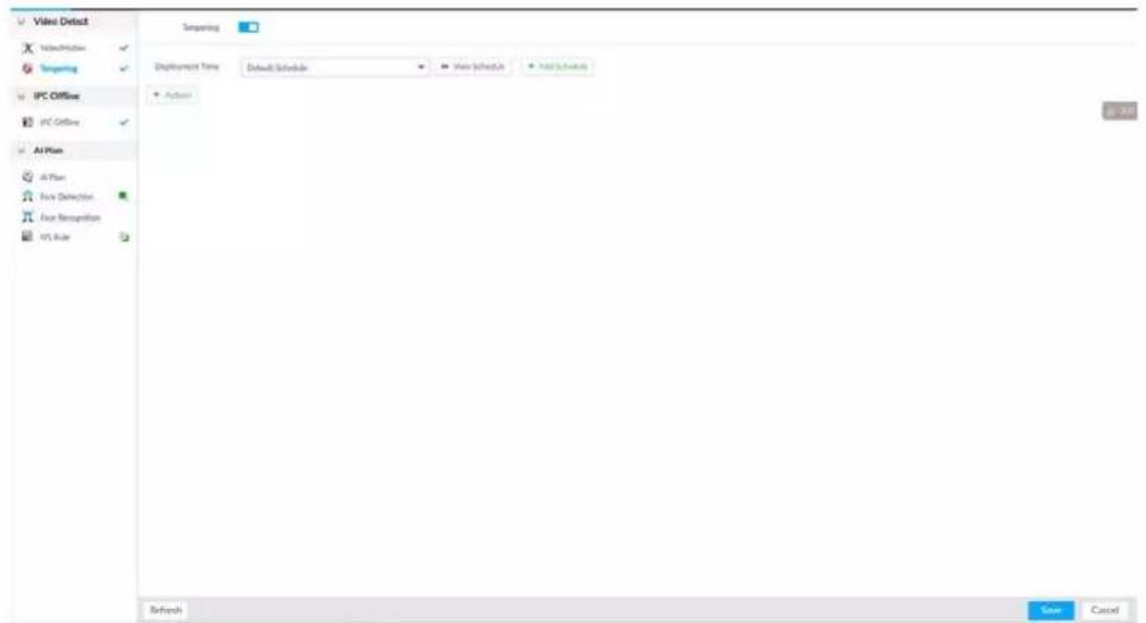
Step 4 Click □ to enable tampering alarm.
Step 5 Click Deployment Time to select schedule from the drop-down list.
After setting deployment period, system triggers corresponding operations when there is a motion detection alarm in the specified period.
- Click View Schedule to view detailed schedule settings.
- If the schedule is not added or the added schedule does not meet actual needs, click Add Schedule. See "8.8.4 Schedule" for detailed information.
Step 6 Click Actions to set alarm actions. See "8.4.1 Alarm Actions" for detailed information.
Step 7 Click Save.
8.4.3.2 Offline Alarm
When the remote device and the IVSS are disconnected, system can trigger an alarm.
Step 1 Click 🎨, or click + on the configuration page, and then select EVENT.
Step 2 Select a remote device in the device tree on the left.
Step 3 Select Device Offline > Device Offline.
Figure 8-63 IPC offline
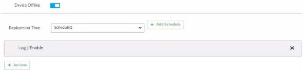
Step 4 Click □ to enable offline alarm.

The device offline alarm is enabled by default. You can skip this step.
Step 5 Click Deployment Time to select schedule from the drop-down list.
After setting deployment period, system triggers corresponding operations when there is a device offline alarm in the specified period.
- Click View Schedule to view detailed schedule settings.
- If the schedule is not added or the added schedule does not meet actual needs, click Add Schedule. See "8.8.4 Schedule" for detailed information.
Step 6 Click Actions to set alarm actions. See "8.4.1 Alarm Actions" for detailed information.
Step 7 Click Save.
8.4.3.3 IPC External Alarm
Set IPC alarm input event, so that when there is an alarm input to the IPC, IPC uploads the alarm to the Device. If the camera has multiple IO channels, you can set the alarm input event for each of them as you might need.
Step 1 Click ⚙, or click + on the configuration page, and then select EVENT.
Step 2 Select a remote device in the device tree on the left.
Step 3 Select External Alarm > IO1.
Figure 8-64 IO1
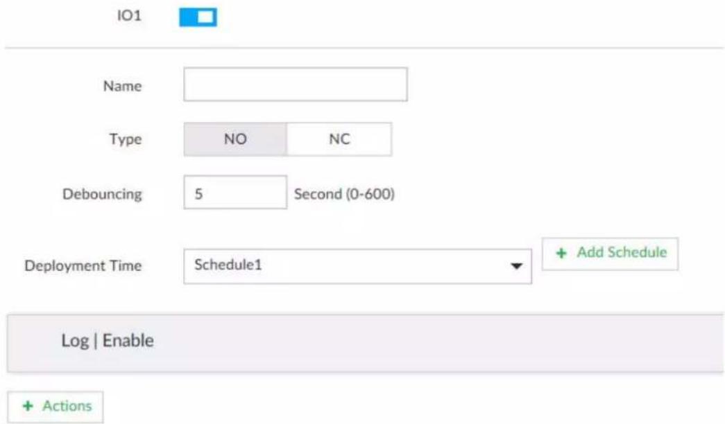
Step 4 Click □ to enable the alarm.
Step 5 Set parameters.
Table 8-24 Local alarm parameters description
| Parameters | Description |
| Name In the Alarm name box, enter a name for the alarm. | |
| Type | Select alarm input device type. Both NO and NC are supported. |
| Debouncing | The system records only one event during this period. |
Step 6 Click Deployment Time to select schedule from the drop-down list.
After setting deployment period, system triggers corresponding operations when there is a motion detection alarm in the specified period.
- Click View Schedule to view detailed schedule settings.
- If the schedule is not added or the added schedule does not meet actual needs, click Add Schedule. See "8.8.4 Schedule" for detailed information.
Step 7 Click Actions to set alarm actions. See "8.4.1 Alarm Actions" for detailed information.
Step 8 Click Save.
8.4.3.4 Thermal Alarm

- Alarm types vary depending on the models of thermal cameras.
- Make sure that configurations of thermal detections such as fire detection and temperature detection have been done on the thermal camera.
Support the following thermal camera alarms.
Table 8-25 Thermal alarms
| Function | Description |
| Fire alarm | When the thermal camera detects a fire, the alarm signal is transmitted to the Device, which performs an alarm linkage action. |
| Temperature alarm | When the thermal camera detects that the temperature is above or below the threshold value, the alarm signal is transmitted to the Device, which performs an alarm linkage action. |
| Temperature difference alarm | When the thermal camera detects a temperature difference greater than the set value, the alarm signal is transmitted to the Device, and the Device will perform an alarm linkage action. |
| Hot spot alarm | When the maximum temperature detected by the thermal camera is higher than the set value, the alarm signal is transmitted to the Device, and the Device will perform an alarm linkage action. |
| Cold spot alarm | When the lowest temperature detected by the thermal camera is below the set value, the alarm signal is transmitted to the Device, and the Device will perform an alarm linkage action. |
This section uses the procedure of configuring fire alarm as an example.
Step 1 Click 🎨 or click + on the configuration page, and then select EVENT.
Step 2 Select the root node in the device tree on the left.
Step 3 Select Thermal Alarm > Fire Alarm.
Step 4 Click Deployment Time to select schedule from the drop-down list.
After setting deployment period, system triggers corresponding operations when there is a motion detection alarm in the specified period.
- Click View Schedule to view detailed schedule settings.
- If the schedule is not added or the added schedule does not meet actual needs, click Add Schedule. See "8.8.4 Schedule" for detailed information.
Step 5 Click Actions to set alarm actions. See "8.4.1 Alarm Actions" for detailed information.
Step 6 Click Save.
8.5 Storage Management
Click 🎨 or click + on the configuration page, select STORAGE. The Local Hard Disk page is displayed. Manage storage resources (such as recording file) and space, so you can use and improve utilization ratio of storage space.

The system supports pre-check and routine inspection, and displays health status, so you can obtain real-time status of device and avoid data loss.
- Pre-check: During device operation, the system automatically detects disk status in case of change (reboot, insert and pull the disk).
- Routine inspection: the system carries out routine inspection of the disk continuously. During device operation, the disk might go wrong due to service life, environment and other factors. Find out any problems during routine inspection.
8.5.1 Storage Resource
8.5.1.1 Local Hard Disk
The local hard disk refers to the HDD installed on the system. You can view HDD space (free space/total space), temperature (centigrade/Fahrenheit), HDD information and so on.
Click 📋, or click + on the configuration page, and then select STORAGE > Storage Resource > Local Hard Disk. There is a corresponding icon near the HDD name after you create the RAID and hot spare HDD.
- : RAID HDD.
• : Global hot spare HDD. - : Invalid HDD of RAID group.

Slight difference might be found on the user interface.
Figure 8-65 HDD
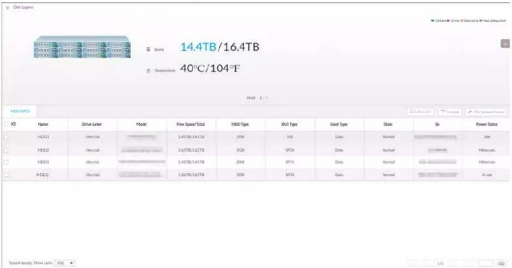
8.5.1.1.1 Viewing S.M.A.R.T
S.M.A.R.T is Self-Monitoring Analysis and Reporting Technology. It is a technical standard to check HDD drive status and report potential problems. System monitors the HDD running status and compares with the specified safety value. Once the monitor status is higher than the specified value, system displays alarm information to guarantee HDD data security.

Check one HDD to view S.M.A.R.T information at one time.
On the Local Hard Disk page, select a HDD, and then click S.M.A.R.T. The S.M.A.R.T page is displayed. Check whether the HDD status is OK or not. If there is any problem, fix it in time.
Figure 8-66 S.M.A.R.T
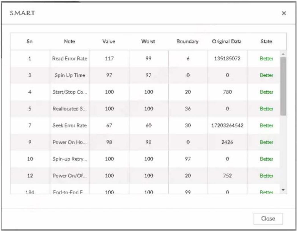
8.5.1.1.2 Format

- Formatting HDD will clear all data on the HDD. Be careful!
- Hot spare HDD cannot be formatted.
Enter the Local Hard Disk page, select HDD, and click Format. It is to format the selected HDD.
8.5.1.1.3 File System Repair
Once you cannot mount the HDD or you cannot properly use the HDD, you can try to use the File System Repair function to fix the problem.
Enter the Local Hard Disk page, select one or more HDD(s) you cannot mount, and click File System Repair, you can repair the selected file system of the corresponding HDD(s). The repaired HDD can work properly or to be mounted.
8.5.1.2 RAID
RAID (Redundant Array of Independent Disks) is a data storage virtualization technology that combines multiple physical HDD components into a single logical unit for the purposes of data redundancy, performance improvement, or both.

- The Device supports RAID0, RAID1, RAID5, RAID6, RAID10, RAID50 and RAID60. See "Appendix 3 RAID" for detailed information.
- You are recommended to use enterprise HDD when you are creating RAID, and use surveillance
HDD for single-HDD mode.
8.5.1.2.1 Creating RAID
RAID has different levels such as RAID5, RAID6 and so on. Different RAID levels have different data protection, data availability and performance levels. Create RAID according to your actual requirements.

Creating RAID operation is going to clear all data on these HDD. Be careful!
Procedure
Step 1 Click ⚙, or click + on the configuration page, and then select STORAGE > Storage Resource > RAID > RAID.
Figure 8-67 RAID (1)

Step 2 Click Add.
Figure 8-68 Create RAID (1)
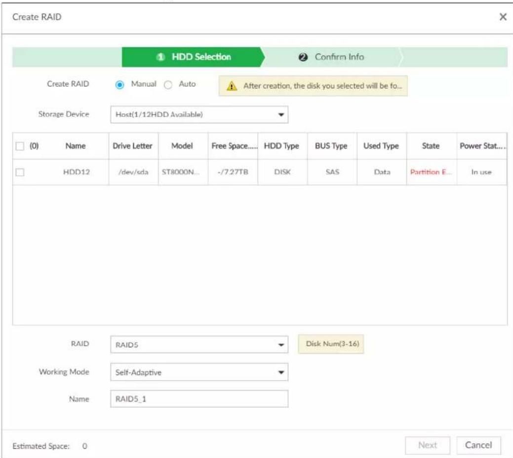
Step 3 Set RAID parameters.
Select RAID creation type according to actual situation. It includes Manual RAID and Auto
RAID.
- Manual RAID: System creates a specified RAID type according to the selected HDD amount.
1) Select Manual RAID.
2) Select HDD you want to use.
3) Set parameters.
Table 8-26 Manual creation parameters description
| Parameters | Description |
| Storage Device | Select storage device of the HDD and select the HDD you want to add to the RAID.Different RAID types need different HDD amounts. |
| RAID | Select a RAID type you want to create. |
| Working mode | Set RAID resources allocation mode. The default setup is self-adaptive.Self-adaptive means the system can automatically adjust RAID synchronization speed according to current business load. When there is no external business, the synchronization speed is at high speed. When there is external business, the synchronization speed is at low speed.Sync first: Allocate resources to RAID synchronization first.Business first: Allocate resources to business first.Load-Balance: Allocate resources to business and RAID synchronization equally. |
| Name Set RAID name. |
- Auto: System creates RAID5 according to the HDD amount.
1) Select Auto.
Figure 8-69 Create RAID (2)
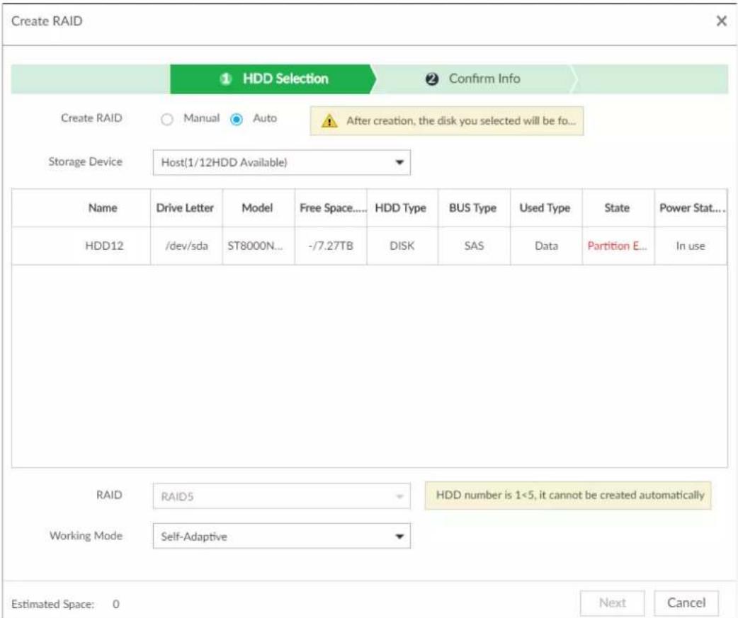
2) Set parameters.
Table 8-27 Auto parameters description
| Parameters | Description |
| Storage Device | Select storage device of the HDD. |
| Working Mode | Set RAID resources allocation mode. The default setup is self-adaptive.Self-adaptive means the system can automatically adjust RAID synchronization speed according to current business load.When there is no external business, the synchronization speed is at high speed. When there is external business, the synchronization speed is at low speed.Sync first: Allocate resources to RAID synchronization first.Business first: Allocate resources to business first.Load-Balance: Allocate resources to business and RAID synchronization equally. |
Step 4 Click Next.
Figure 8-70 Confirm info (manual)
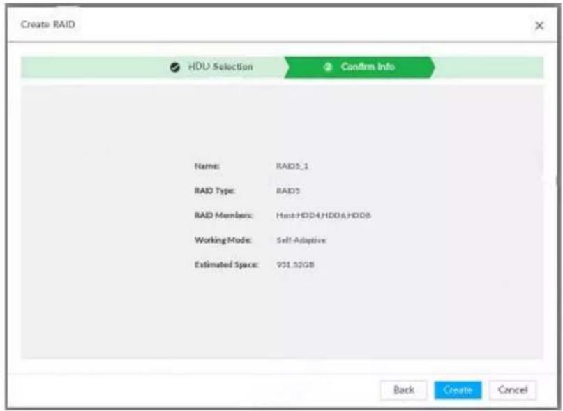
Figure 8-71 Confirm info (Auto)
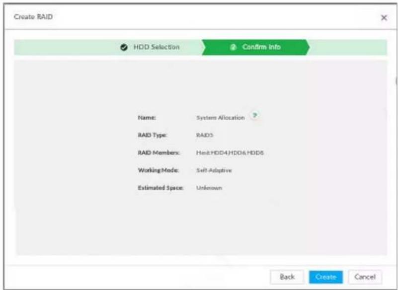
Step 5 Confirm information.

If the input information is wrong, click Back to set RAID parameters again.
Step 6 Click Create.
System begins to create RAID. It displays RAID information after creation.
Figure 8-72 RAID (2)

Related Operations
After creating RAID, view RAID disk status and details, clear up RAID, and repair file system.
Table 8-28 RAID operation
| Name | Operation |
| View RAID HDD status | Click ▶ at the right side of the RAID name to open the RAID HDD list. It is to view RAID HDD space, status and so on. |
| View RAID details | Click Ⓐ to view RAID detailed information. |
| File System Repair | Once you cannot mount the RAID or you cannot properly use the RAID, you can try to use repair file system function to fix.Enter RAID page, select one or more RAID(s) you cannot mount, click File System Repair, you can repair the selected file system of the corresponding RAID(s). The repaired RAID can work properly or to be mounted. |
| Modify Working Mode | Select one or more RAIDs, and then clickWorking Mode to modify the working mode. |
| Format RAID | Enter RAID page, select one and more RAID groups. ClickFormat to format the selected RAID.[RANTH]Formatting RAID is to clear all data on the RAID and cancel the RAID group. Please be careful. |
| Delete RAID | Enter RAID page, select one and more RAID groups. ClickDelete to delete the selected RAID.[IMAGE]Deleting RAID is to clear all data on the RAID and cancel the RAID group. Please be careful. |
8.5.1.2.2 Creating Hot Spare HDD
When a HDD of the RAID group is malfunctioning or has a problem, the hot spare HDD can replace the malfunctioning HDD. There is no risk of data loss and it can guarantee storage system reliability.
Step 1 Click 🎨, or click + on the configuration page, and then select STORAGE > RAID > Hot spare.
Figure 8-73 Hot spare (1)
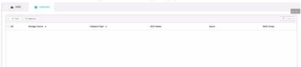
Step 2 Click Add.
Figure 8-74 Global hot spare
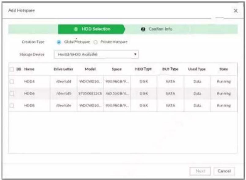
Figure 8-75 Private hot spare
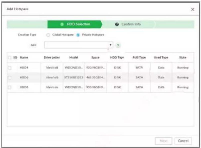
Step 3 Select hot spare creation type.
- Global hot spare: Create hot spare for all RAID. It is not a hot spare HDD for a specified RAID group.
- Private hot spare: Select Private Hot spare and Add it to a RAID group. The private hot spare HDD is for a specified RAID group.
Step 4 Select one or more HDD(s) and then click Next.
Figure 8-76 Confirm info
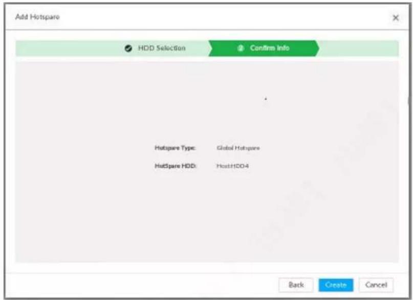
Step 5 Confirm information.

Click Back to select hot spare HDD(s) again if you want to change settings.
Step 6 Click Create to save settings.
System displays the added hot spare HDD information.
Figure 8-77 Hot spare (2)


Select a hot spare HDD and then click Delete, it is to delete hot spare HDD.
8.5.1.3 Network Hard Disk
Network hard disk is a network-based online storage service that stores device information in the network hard disk through the iSCSI protocol.
8.5.1.3.1 iSCSI Application
View network hard disk usage, including remaining capacity, and hard disk status.
Click 📷 or click + on the configuration page, and then select STORAGE > Storage Resource > Network Hard Disk > iSCSI Application.
Figure 8-78 ISCSI application
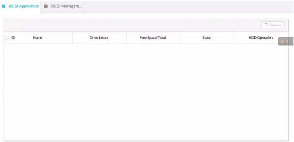
- Select a network hard disk, and then click Format to format the disk. Formatting your hard disk will erase all data from your hard disk, so do it carefully.
- Click the HDD Operation column, and then you can select an HDD operation permission type.
Read/Write: One can read, edit, add, and delete data of this disk.
Read Only: One can only read data of this disk.
8.5.1.3.2 iSCSI Management
Set up the network disk through iSCSI and map the network disk to the device so that the device can use the network disk for storage.

Make sure that service has been enabled on the iSCSI server and the server has provided the shared file directory.
Step 1 Click 🎨, or click + on the configuration page, and then select STORAGE > Network Hard Disk > iSCSI Management.
Figure 8-79 Network hard disk
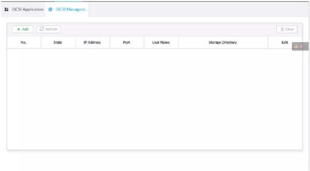
Step 2 Click. +
Figure 8-80 Add iSCSI
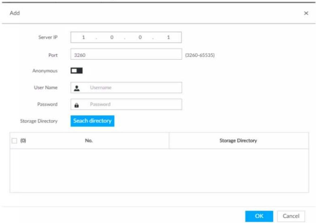
Step 3 Set parameters.
Table 8-29 Network hard disk parameters
| Parameters | Description |
| Server IP Enter iSCSI server IP address. | |
| Port | Enter iSCSI server port number. It is 3260 by default. |
| Anonymous | If iSCSI server has no permission limitation, you can select anonymous login.indicates that anonymous login is enabled and there is no need to set username and password.indicates that anonymous login is disabled. |
| User Name | If access permission has been limited when creating the shared file directory on the iSCSI server, you need to enter username and password. |
| Password | |
| Storage Directory | Click Search Directory to select the storage directory. The storage directory is generated when the shared file directory is being created on the iSCSI server. Each directory is an iSCSI disk. The storage directory is generated when the shared file directory is being created on the iSCSI server. Each directory is an iSCSI disk. |
Step 4 Click OK.
The added network disk is displayed.

- Click to delete a disk; click Refresh to refresh the disk list.
- On the Disk Group page, you can configure network disk groups. For details, see "8.5.2.1.1 Setting Disk Group".
8.5.2 Video Recording
8.5.2.1 Storage Mode
Allocate disks or RAID groups to different disk groups, and store video and image to specified disk group.
8.5.2.1.1 Setting Disk Group
Disk and created RAID group are allocated to group 1 by default. You can allocate disk and RAID group to other groups according to your actual needs.
The default number of disk group is the same as the maximum number of HDD that IVSS supports.
Fox example, the Device supports a maximum number of 16 HDDs, and then the default number of disk group is 16.
Step 1 Click ⚙, or click + on the configuration page, and then select STORAGE >VIDEO RECORDING >Storage Mode >Disk Group.

- The value (such as 1) next to the group name refers to the number of HDD and RAID group in the disk group. If instead, 1 is displayed, it means no available HDD or RAID group in the disk group, but there is video or image stored in the disk group.
• indicates picture storage. indicates video storage
Step 2 Click a disk group.
Figure 8-81 Disk group
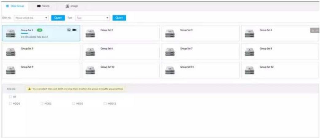
Step 3 Select HDD or RAID group from Disks, and then drag the HDD or the RAID group to another disk group.
Disk grouping takes effect immediately.

Select All to select all the HDDs and RAID groups of the disk group.
After configuring disk groups, you can also view which disk group the selected disk, video or picture belongs to.
Table 8-30 Disk group functions
| Function | Description |
| View the disk group of a disk, video or picture | Click , select a disk or RAID group, and then click Query to search for the disk group that the selected disk or RAID group belongs to. |
| View disk groups of video or image | Select Video or Image from , and then-click Query to search for disk groups of the selected type. |
8.5.2.1.2 Setting Video/Image Storage
Videos/images of all channels are stored in disk group 1 by default. You can store the videos/images in different disk groups according to actual needs. Two methods are available to set video/image storage.

This section uses storing video for example. To store images, the procedure is similar.
Method 1: Selecting Disk Group
Step 1 Click 🎨, or click + on the configuration page, and then select STORAGE >VIDEO RECORDING >Storage Mode >Video.
Figure 8-82 Video
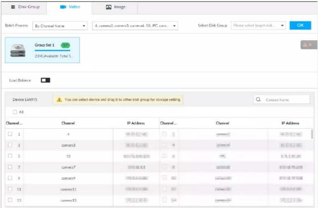
Step 2 Select filtering way from the Batch Process drop-down list.
- By Channel Name: Select channel according to the channel name.
- By Logical Channel No.: Select channel that is connected to the Device. In this case, Start Channel No. and End Channel No. need to be configured.
Step 3 In the Select Disk Group drop-down list, select target disk group.

In the drop-down list, only disk group with available HDD or RAID group is displayed.
Step 4 Click OK.
Step 5 Disk grouping takes effect immediately.
Method 2: Dragging Channel
Step 1 Click 🎨 or click + on the configuration page, and then select VIDEO RECORDING > Storage Mode > Video.
Step 2 Click a disk group.
The linked channels of the disk group are displayed in Device List.

- Only disk group with available HDD or RAID group or linked channel is displayed.
- The value (such as 1) next to the group name refers to the number of HDD and RAID group in the disk group. If instead, 9 is displayed, it means no available HDD or RAID group in the disk group, but there is video or image stored in the disk group.
Figure 8-83 Device list
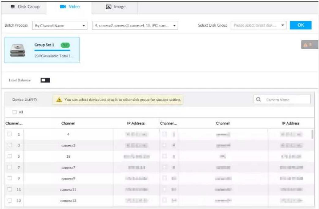
Step 3 (Optional) Click □ to enable load balance, and then the icon turns into blue. To disable it, click it again, and then the icon turns into gray.
- After load balance is enabled, if one disk group has no usable disk, the video of all channels that belong to this disk group will be stored into all the usable disk groups.
- When load balance is not enabled, if one disk group has no usable disk, the video of all channels that belong to this disk group will be stored in another usable disk group.
Step 4 Select a channel from the device list, and drag the channel to the target disk group.
Step 5 Disk grouping takes effect immediately.
8.5.2.2 Recording Schedule
Configure recording modes and schedules for channels.
8.5.2.2.1 Recording Mode
Configure recording modes for channels.
Step 1 Click ⚙, or click + on the configuration page, and then select STORAGE > VIDEO RECORDING > Schedule.
Step 2 Find the camera for which you want to configure a recording schedule, select the recording methods for the stream types.
• means that the type is selected.
- Substream1 and Substream2 cannot be enabled at the same time.
- Auto: Records automatically according to the schedule.
- Manual: Records around the clock and does not respond to the recording schedule.
- Close: No recording and does not respond to the recording schedule.
Step 3 Select a recording method.
Step 4 (Optional) click □ to disabled the recording schedule configuration of the selected channel
Step 5 Click Save.
Figure 8-84 Recording Mode
| DEVICE INFO | Record Mode | |||||||||||
| Main Stream | Substream1 | Substream2 | ||||||||||
| Channel No | Channel | Auto | Man... | Close | ○ Auto | ○ Man... | ○ Close | ○ Auto | ○ Man... | ○ Close | ||
| 1 | camera1 | ● | ○ | ○ | ○ | ● | ○ | ○ | ○ | ● | ||
| 2 | camera2 | ● | ○ | ○ | ○ | ○ | ● | ○ | ○ | ● | ||
8.5.2.2.2 Recording Schedule
Configure video and picture recording schedules so the Device records and captures pictures as configured in the specified period.
Step 1 Click 🎨 or click + on the configuration page, and then select STORAGE >VIDEO RECORDING > Schedule.
Step 2 Click 📋 and then set a recording schedule.
Figure 8-85 Set a recording schedule
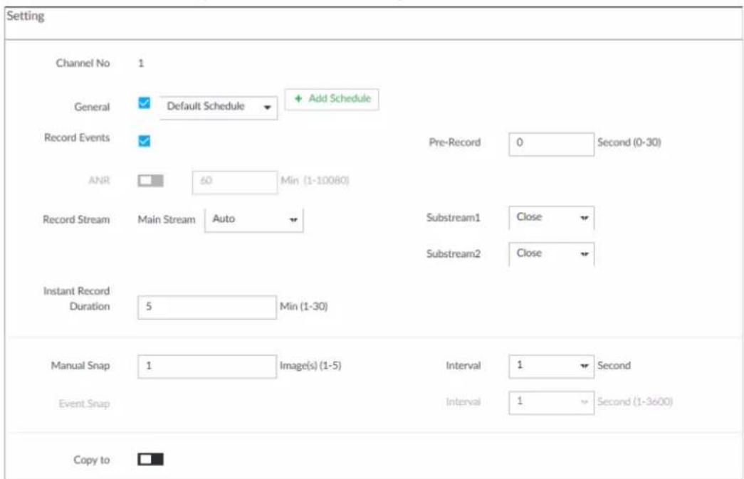
- Set General recoding schedule.
- Select the General checkbox to enable the function.
- Click Add Schedule.
- Click +, name the schedule, select a type and then click OK.
- Specify recording hours by dragging the sliders on the day bars.
• Always Effective: Records according to the schedule. - Customize: Select this option, click + to define the validity periods of the schedule.
Figure 8-86 Add a schedule
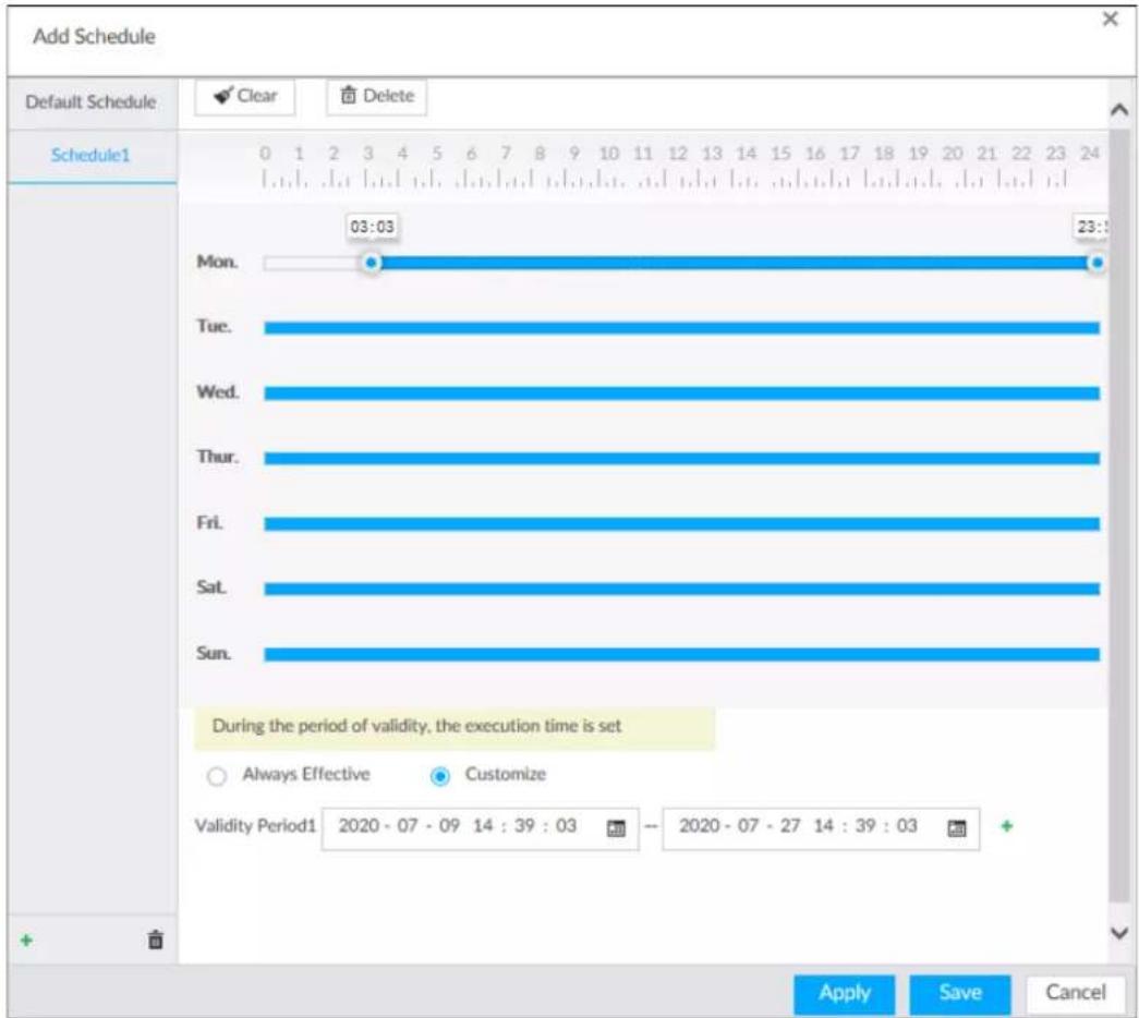
6. Click Save.
Step 3 Set other parameters and then click OK.
- Record Events: Record event videos.
- Pre-record: The recording duration prior to the event.
- ANR: Automatic Network Replenishment. When ANR is enabled (by clicking ), the Device will download videos recorded by IPC and stored on camera SD card during network disconnection. Enter the time length of the video to be downloaded from IPC. The Device will download only the defined length of video even if the disconnection is longer.

Make sure that the IPC has an SD card and is recording.
- Record Stream: Select stream types and recording modes.
- Instant Record Duration: The duration of instant recording. After starting instant recording on the LIVE page, if you do not stop recording, it will automatically stops after the defined duration.
- Manual Snap: The number of images for each manual capture action. Enter a value to specify the number of seconds between each image.
- Event Snap: The number of images captured for each event.
- Copy to: Copy the current settings to other channels.
8.5.2.3 Basic
Configure the storage mode when the disk space is used up and the automatic deletion of expired files.
8.5.2.3.1 Setting Storage Mode
Configure the storage mode when there is no more disk space available.
Step 1 Log in to PCAPP.
Step 2 Click 🎨, or click + on the configuration page, and then select STORAGE >VIDEO RECORDING >Storage Mode.
Step 3 Set storage mode.
- Overwrite: When HDD free space is less than 100 GB or 2% of the total space (the larger of the two values prevails), the Device deletes 100 GB of the earliest record files and continues to record.

Data will be overwritten in the Overwrite mode. Back up in time.
- Stop: When HDD free space is less than the defined free space alarm rate of the total space, an alarm is triggered and the Device continues recording until HDD free space is used up.
Figure 8-87 Storage mode
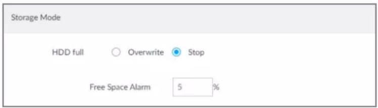
Step 4 Click Save.
8.5.2.3.2 Setting Automatic File Deletion
You can enable the Device to automatically delete files older than a certain number of days.
Step 1 Log in to PCAPP.
Step 2 Click 🎨, or click + on the configuration page, and then select STORAGE >VIDEO RECORDING >Storage Mode.
Step 3 Set automatic file deletion.
- Never: The Device does not delete files automatically.
- Customize: The Device automatically deletes files older than the configured number of days.

The deleted files cannot be recovered.
Figure 8-88 Delete expired files

Step 4 Click Save.
8.5.2.4 Record Transfer
When the device and an IPC are disconnected, the IPC continues to record and stores the recording in the SD card. After the network is recovered, the device will download the recording during the disconnection from the IPC.
Two ways for record transfer after the network recovers.
- Automatic download: After the network recovers, the device automatically downloads the recording in the set time period.
- Manual download: If ANR is not enabled when you set the recording schedule, after the network recovers, the device can not automatically download the recording during the disconnection, but the user can manually create the download task.
Step 1 Click 🎨 or click + on the configuration page, and then select STORAGE >VIDEO RECORDING >Record Transfer.
Step 2 Click Add.
Figure 8-89 Add
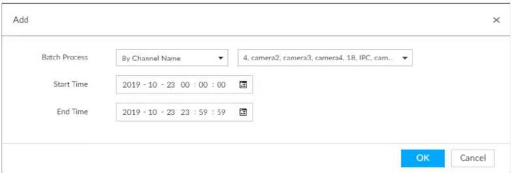
Step 3 Select By Channel Name or By Channel No. in the Batch Process drop-down list. Step 4 Set time period of the video to be searched.
Step 5 Click OK. The transfer progress is displayed.

Select a transfer task, click Delete to delete it. A task in progress cannot be deleted.
8.6 Security Strategy
Click 📍 or click + on the configuration page, select SECURITY. The SECURITY page is displayed. Set security strategy to guarantee device network and data safety. It includes HTTPS, set host IP access rights, enable network security protection.
8.6.1 HTTPS
HTTPS can use the reliable and stable technological means to guarantee user information and device security and communication data security. After installing the certificate, you can use the HTTPS on the PC to access the device.

- HTTPS function is for web interface and PCAPP only.
- You are recommended to enable HTTPS service. Otherwise, you might risk data leakage.
8.6.1.1 Installing Certificate
There are two ways to install the certificate.
- Manually create a certificate and then install.
- Upload a signature certificate and then install.
8.6.1.1.1 Installing the Created Certificate
Install the created certificate manually. It includes creating the certificate on the device, downloading and installing the certificate on the PC.

- Create and install root certificate if it is your first time to use HTTPS or you have changed device IP address.
- After creating server certificate and installing root certificate, download and install root certificate on the new PC, or download the certificate and then copy to the new PC.
Step 1 Click 🎨, or click + on the configuration page, and then select SECURITY > Credential.
Step 2 Create certificate on the device.
1) Click Create certificate.
2) Set parameters as required.

IP/domain shall be the device IP or the domain.
3) Click OK. System begins to install certificate, and then displays certificate information after the installation.
Step 3 Download certificate.
1) Click . Download
The Opening ca.crt page is displayed.
2) Click Save File to select file saving path.
3) Click Save.
System begins downloading certificate file.
Step 4 Install root certificate on the PC.
1) Double-click the certificate.
System displays Open file-security warning page.
2) Click Open.
3) Click Install Certificate.
4) Follow the prompts to import the certificate.
System goes back to Certificate page.
Step 5 Click OK to complete certificate installation.
Figure 8-90 Installed certificate
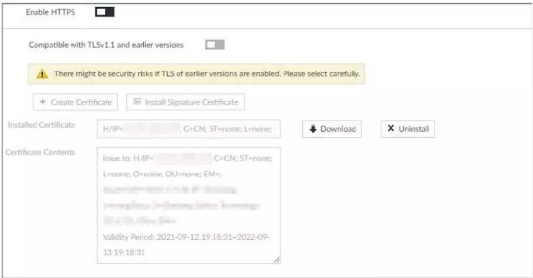
8.6.1.1.2 Installing Signature Certificate
Upload signature certificate to install.
Prerequisites
Before installation, make sure that you have obtained safe and valid signature certificate.
Procedure
Step 1 Click 🎨 or click + on the configuration page, and then select SECURITY > Credential.
Step 2 Click Install Signature Certificate.
Figure 8-91 Install signature certificate
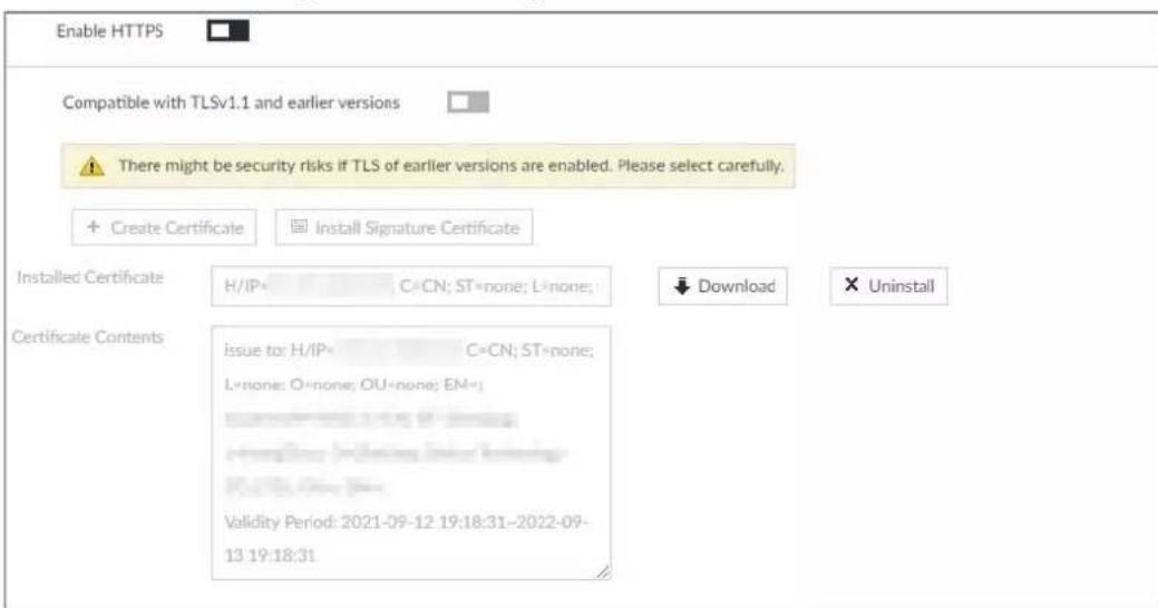
Step 3 Click Browse and then select certificate and credential file.
Step 4 Click Install.
System begins to install certificate, and then displays certificate information after the
installation.
Step 5 Install the root certificate on the PC. See "8.6.1.1.1 Installing the Created Certificate" for detailed information.

This root certificate is the one obtained with signed certificate.
8.6.1.2 Enabling HTTPS
After you install the certificate and enable HTTPS function, you can use the HTTPS on the PC to access the device.
Step 1 Click 🎨, or click + on the configuration page, and then select SECURITY > Credential.
Step 2 Click □ to enable HTTPS function.
Step 3 Click □ to enable Compatible with TLSv1.1 and earlier versions.

TLS (Transport Layer Security) provides privacy and data integrity between two communications application programs.
Figure 8-92 Credential
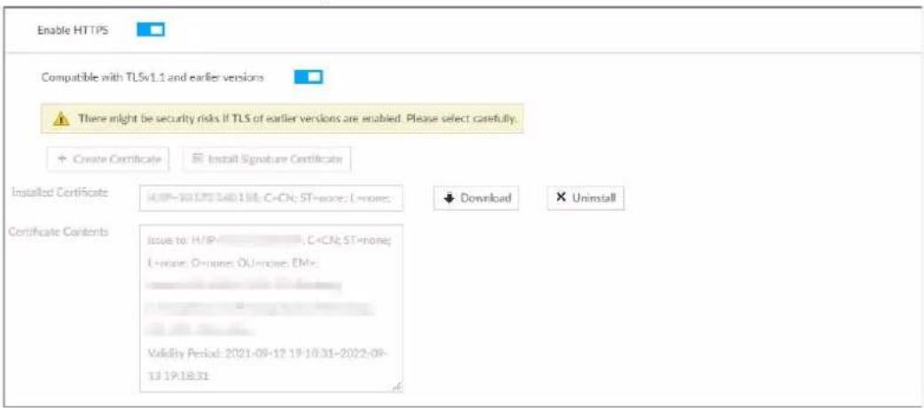
Step 4 Click Save.
After you successfully save the settings, you can use HTTPS to access the web interface. Open the browser, enter https://IP address:port in the address bar, and then press Enter, and the login page is displayed.

- IP address is device IP or the domain name.
- Port refers to device HTTPS port number. If the HTTPS port is the default value 443, just use https://IP address to access.
8.6.1.3 Uninstalling the Certificate
Uninstall the certificate.

- You cannot use the HTTPS function after you uninstall the certificate.
- The certificate cannot be restored after being uninstalled. Be cautious.
Step 1 Click 🎨 or click + on the configuration page, and then select SECURITY > Credential.
Figure 8-93 Uninstall
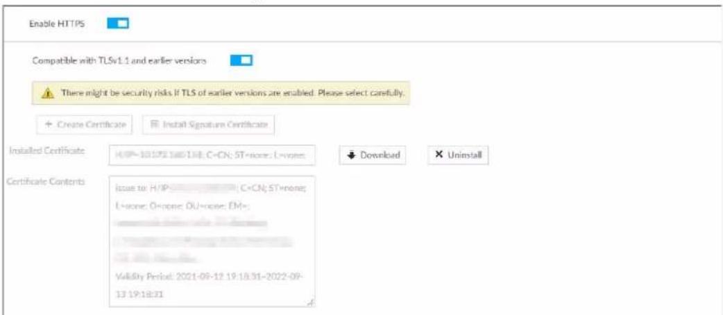
Step 2 Click Uninstall.
System pops up a confirmation box.
Step 3 Click OK to uninstall the certificate.
8.6.2 Configuring Access Permission
Set the specified IP addresses to access the device, to enhance device network and data security.
Step 1 Click 🎨, or click + on the configuration page, and then select SECURITY > IP Filter.
Figure 8-94 IP Filter
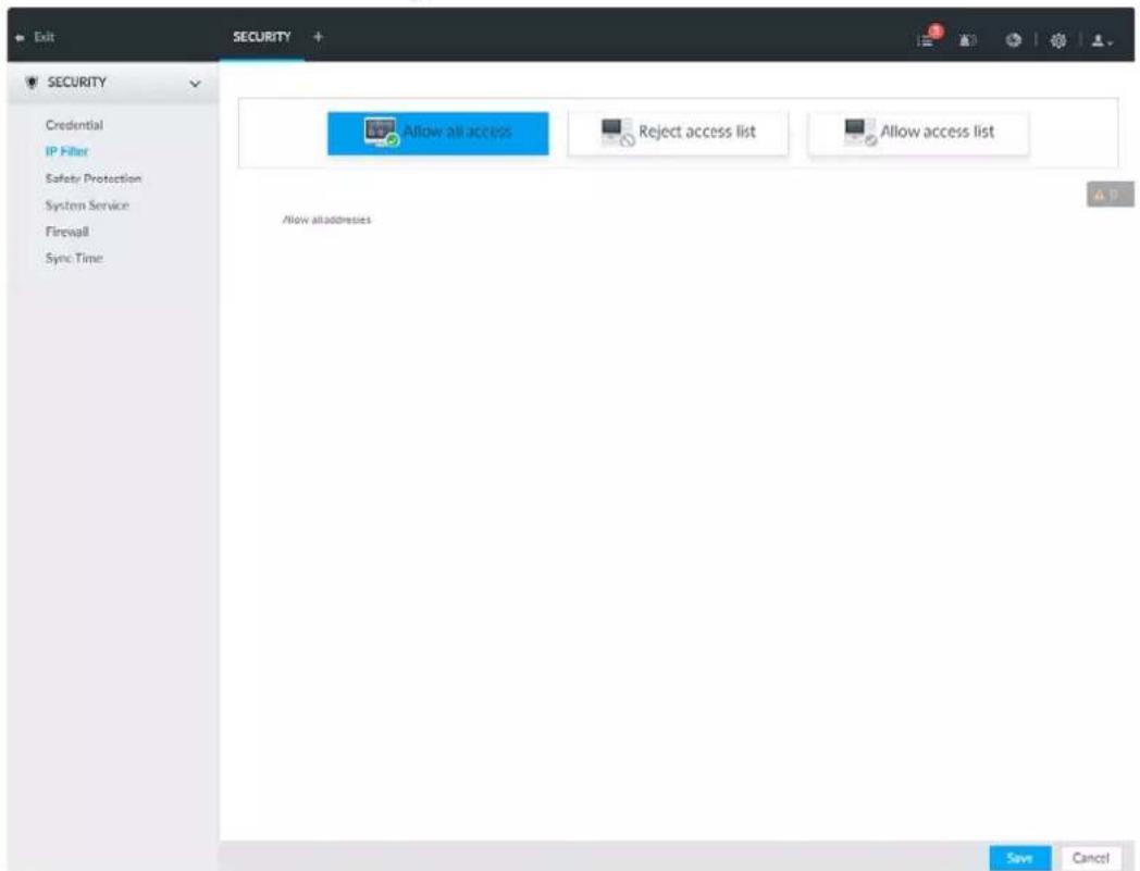
Step 2 Select IP access rights.
- Allow all access: It is to allow all IP addresses in the same IP segment to access the device.
- Reject access list: It means the IP address in the list cannot access the device.
- Allow access list: It means the IP address in the list can access the device.
Step 3 Add IP host.

The following steps are to set reject access list or allow access list.
1) Click Add.
2) Select Add Type, and set IP address or MAC address of IP host.
- Single IP: Enter host IP address.
- IP segment: Enter IP segment. It can add multiple IP addresses in current IP segment.
• MAC: Enter MAC address of IP host.
3) Click OK to add the IP host.
System displays added IP host list.

- Click Add to add more IP hosts.
- Click to edit the IP host.
- Select an IP host and then click Delete to delete.
Step 4 Click Save.
8.6.3 Safety Protection
Set the login password lock strategy once the login password error has exceeded the specified threshold within the defined time period. System can lock current IP host for a period of time.
Step 1 Click 📍, or click + on the configuration page, and then select SECURITY > Safety Protection.
Figure 8-95 Safety protection (1)
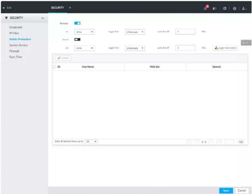
Step 2 Click □ to enable security protection function.
- Remote: When you are using web interface, PCAPP to access the device remotely, once the login password error has exceeded the threshold within the defined time period, system locks the IP host for a period of time.
- Local: When you are accessing local menu of the device, once the login password error has exceeded the threshold within the defined time period, system locks the account for a period of time.
Step 3 Set lock strategy according to the actual situation.
Step 4 Click Save.
Once the IP host has been locked, you can view the locked IP host on the list. Select an IP host and then click Unlock, or click the ☐ of the corresponding IP host to unlock.
Step 5 (Optional) Click Login lock event to go to the Event page where you can select Abnormal Event > Lock in to configure a Lock in event.
8.6.4 Enabling System Service
Enable system services for third-party access.
Step 1 Click 🎨, or click + on the configuration page, and then select SECURITY > System Service.
Figure 8-96 System service
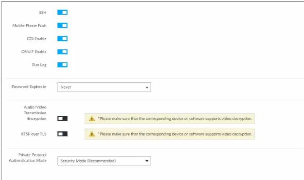
Step 2 Enable or disable system service according to your actual situation.
Table 8-31 System service
| System service | Description |
| SSH | After enabling this function, you can access the Device through SSH protocol to carry out system debugging and IP configuration. This function is disabled by default. You are recommended to disable this function. Otherwise there might be security risks. You are recommended to disable this function. Otherwise there might be security risks. |
| Mobile Phone Push | After enabling this function, you can access the Device with mobile phone client to receive information from the Device. You are recommended to disable this function. Otherwise there might be security risks. You are recommended to disable this function. Otherwise there might be security risks. |
| CGI Enable | After this function is enabled, third-party platform can connect the Device through CGI protocol. You are recommended to disable this function. Otherwise there might be security risks. You are recommended to disable this function. Otherwise there might be security risks. |
| ONVIF Enable | After this function is enabled, other devices can connect the Device through ONVIF protocol. You are recommended to disable this function. Otherwise there might be security risks. You are recommended to disable this function. Otherwise there might be security risks. |
| Run Log | After enabling it, you can view system running logs in Intelligent Diagnosis > Run Log. |
| Password Expires in | Configure the password expiration interval. The Device prompts you to change the password when the password expires. |
| Audio/Video Transmission Encryption | When this function is enabled, stream transmission will be encrypted.We recommend you enable this function. Otherwise you might risk data leakage. |
| RTSP over TLS | Enable this function to encrypt stream transmission.You are recommended to enable this function. Otherwise you might risk data leakage. |
| Private Protocol Authentication Mode | Select a private protocol authentication mode between security mode and compatible mode. Security mode is recommended. |
Step 3 Click Save.
8.6.5 Configuring Firewall
Enhance network and data security by prohibiting Ping and half-connection.
- PING Prohibited: When PING Prohibited is enabled, the device does not respond to Ping requests.
- Anti Half Connection: When Anti Half Connection is enabled, and the device can provide service normally under half-connection attack.
Step 1 Click 🎨 or click + on the configuration page, and then select SECURITY > Firewall.
Figure 8-97 Firewall
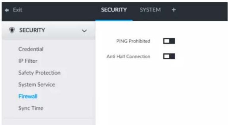
Step 2 Click □ to enable PING Prohibited or Anti Hal Connection.
Step 3 Click Save.
8.6.6 Configuring Time Synchronization Permission
Configure permissions of time synchronization actions from other devices or servers.
Step 1 Click 🎨, or click + on the configuration page, and then select SECURITY > Synch Time.
Step 2 Click □ to enable time synchronization restriction.
Step 3 Select Allowlist or Blocklist.
- Hosts in the allowlist have the permission to synchronize time of the Device.
- Hosts in the blocklist cannot synchronize time of the Device.
Step 4 On the Allowlist page or the Blocklist page, add hosts.
1) Click Add.
Figure 8-98 Add a host
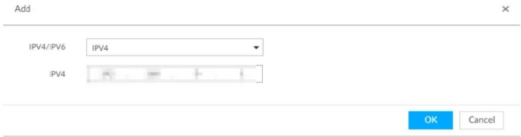
2) Select an IP version, and then enter an IP address.
3) Click OK.
Step 5 Click Save.
You can also perform the following functions after configuring the allowlist or blocklist.
Table 8-32 Other functions
| Function | Description |
| Edit IP address | Click ☑ to edit IP address. |
| Delete IP address | Click ☑ to delete a host from the list. |
| Configure IP address permission | Click the corresponding ☐ each host, so as to enable the allowlist or blocklist configuration for the host.Click ☐ to disable the allowlist or blocklist configuration for the host. |
8.7 Account Management
Device account adopts two-level management mode: user and user group. You can manage their basic information. To conveniently manage the user, we recommend the general user authorities shall be lower than high-level user authorities.

- To ensure device safety, enter correct login password to operate the ACCOUNT page (for example, add or delete user).
- After a correct login password is entered on the ACCOUNT page, if you do not close the ACCOUNT page, you can do other operations directly. If you close the page and enter it again, you shall enter the correct login password again.
8.7.1 User Group
Different users might have different authorities to access the device. You can divide the users to different groups. It is easy for you to maintain and manage the user information.
- System supports maximum 64 user groups. User group name supports maximum 64 characters.
- System has two default user groups (read-only): admin and ONVIF.
- Create new user group under the root.
8.7.1.1 Adding User Group
Step 1 Click 🎨, or click + on the configuration page, and then select ACCOUNT.
Step 2 Select the root node in the device tree on the left and then click 🏠 at the lower-left corner.
Step 3 Enter current user's login password, and then click OK. System creates one user group and displays the Property page.
Figure 8-99 User group property
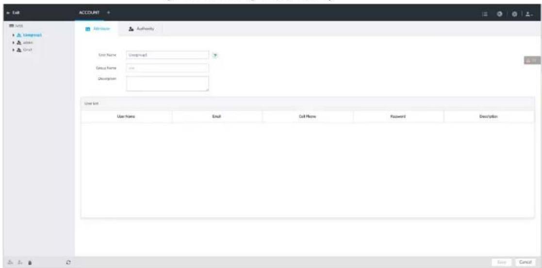
Step 4 Set parameters.
Table 8-33 User group
| Parameters | Description |
| Name | Set user group name.The name ranges from 1 to 64 characters. It can contain English letters, number and special character ("_ ", "@", "."). |
| Group name | Displays user group organization node. System automatically recognizes the group name. |
| Description | Enter user group description information. |
| User list Displays user information of current group. | |
Step 5 Select user authority.
1) Click Authority tab.
Figure 8-100 Authority
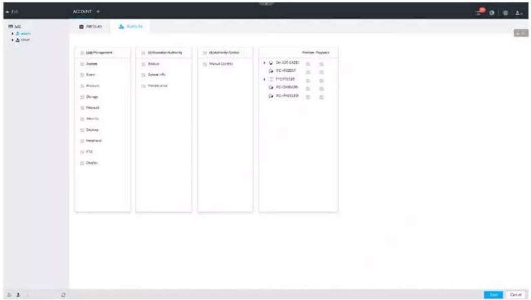
2) Set user group authorities according to actual situation.
• : means it has the corresponding authority.
- Check the box at the top of the authority list (such as (0) Authority Control) to select all authorities of current category.
Step 6 Click Save.
8.7.1.2 Deleting User Group

- Before you delete a user group, delete all users of current group first. User group cannot be restored after being deleted. Be cautious.
- Admin and ONVIF user cannot be deleted.
Step 1 Click 🎨, or click + on the configuration page, and then select ACCOUNT.
Step 2 Select user group and click .
Step 3 Enter current user's login password, and then click OK.
Step 4 Click OK on the prompt page.
8.7.2 Device User
The device user is to access and manage the device. System default administrator is admin. It is to add a user and then set corresponding authorities, so that the user can access the resources within its own rights range only.

User authorities adopt the user group authorities settings. It is read-only.
8.7.2.1 Adding a User
Step 1 Click 🎨, or click + on the configuration page, and then select ACCOUNT.
Step 2 Select admin user group or other newly added user group, and then click 🙏 at the lower-
left corner.
Step 3 Enter current user's login password, and then click OK.
Figure 8-101 Property
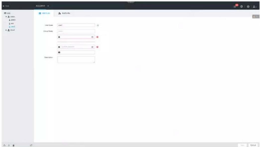
Step 4 Set parameters.
Table 8-34 User management
| Parameters | Description |
| Name | Set username.The name ranges from 1 to 31 characters. It can contain English letters, number and special character ("_", "@", "."). |
| Group name | Displays user organization node. System automatically identifies it. |
| Password | In the new password box, enter the new password and enter it again in the Confirm Password box.The password ranges from 8 to 32 non-empty characters. It can contain letters, numbers and special characters (excluding "";& and space).The password shall contain at least two categories. Usually we recommend the strong password. |
| Confirm Password | |
| Description | Enter user description information. |
Step 5 (Optional) Click Authority tab to view user authority.
Figure 8-102 Authority
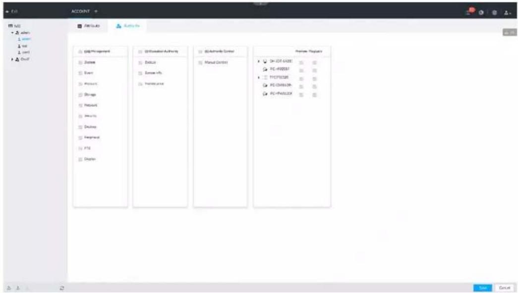
Step 6 Click Save.
8.7.2.2 Operation
After adding a user, you can modify user information or delete the user.

The user with account management authority can change its own and other users' information.
Table 8-35 User operation
| Name | Operation |
| Edit user information | Select a user from user list. The Property page of the user is displayed, and the user's login password and description information can be modified. |
| Delete User | Select a user from user list, and then click to delete. Before deleting an online user, block the user first. For details, see "9.6.1 Online User".User information cannot be restored after being deleted. Be cautious. Before deleting an online user, block the user first. For details, see "9.6.1 Online User".User information cannot be restored after being deleted. Be cautious. |
8.7.3 Password Maintenance
Maintain and manage user's login password.
8.7.3.1 Changing Password
Change user's login password.
8.7.3.1.1 Changing Password of the Current User
Step 1 Click 📁 at the top right corner, and then select Modify Password.
Step 2 Enter the old password, the new password and then confirm.
Step 3 Click OK.
8.7.3.1.2 Changing Password of Other User

Only Admin account supports this function.
Step 1 Click 🎨, or click + on the configuration page, and then select ACCOUNT.
Step 2 Select a user.
Figure 8-103 Property
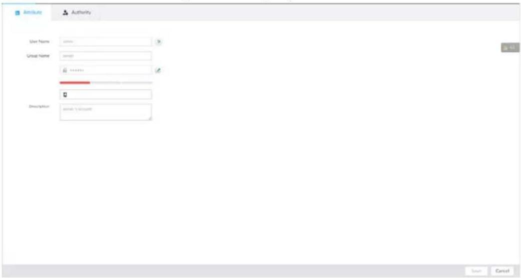
Step 3 Click.
Step 4 Enter current user's login password, and then click OK.
The Change Password page is displayed.
Figure 8-104 Change password
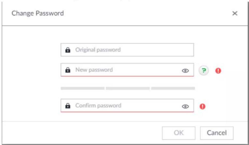
Step 5 In the New Password box, enter the new password and enter it again in the Confirm Password box.
Step 6 Click OK.
8.7.3.2 Resetting Password
You can use email address or answer the security questions to reset password once you forgot it. You can only reset password on the local interface of the Device.

When password resetting function is not enabled, the password cannot be reset if the security questions are not set.
8.7.3.2.1 Leaving Email Address and Security Questions
Enable the password reset function, leave an email address and set security questions. You can only use the local interface to set security questions.
Step 1 Click 🎨, or click + on the configuration page, and then select ACCOUNT.
Step 2 Select the root node in the device tree on the left.
Step 3 Click □ to enable the password reset function.
Step 4 Enter an email address for resetting password.
Step 5 Set security questions. Only available on the local interface of the Device.
Step 6 Click Save.
8.7.3.2.2 Resetting Password on Local Interface
Step 1 Connect a display to the Device, and then go to the Login page of the Device.
Figure 8-105 Login
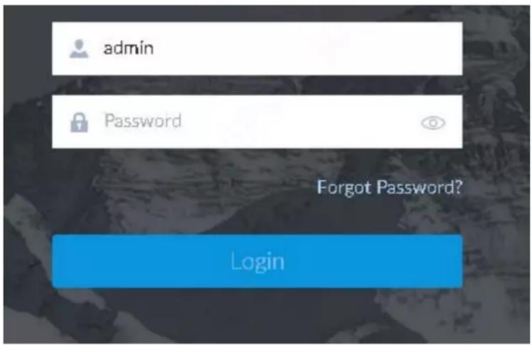
Step 2 Click Forgot Password?.
Step 3 Click OK.
- If you have set the email address information, the QR code is displayed.
- If you have not set the email address information, the email address interface is displayed. After you set the email address information and clickNext, the QR code is displayed.
Figure 8-106 Enter email address
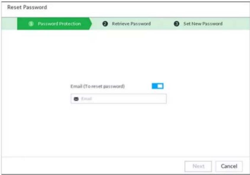
Figure 8-107 Scan QR code
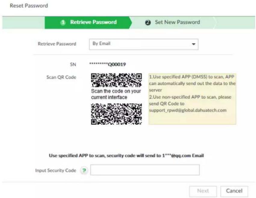
Step 4 Reset the password.
Figure 8-108 Security questions
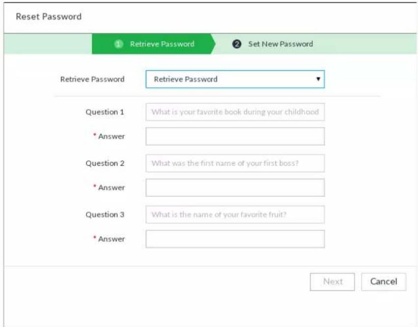
Step 5 Click Next.
Figure 8-109 New password setting
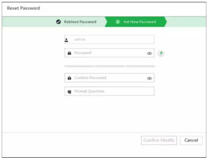
Step 6 Set parameters.
Table 8-36 Description of password parameters
| Parameters | Description |
| User The default username | is admin. |
| Password | In the New Password box, enter the new password and enter it |
| Confirm Password | again in the Confirm Password box.The password must consist of 8–32 non-blank characters and contain at least two types of the following characters: Uppercase, lowercase, numbers, and special characters (excluding '"; : &). Enter a strong password according to the password strength indication. |
| Prompt question | After setting the prompt, when you point to on the login page, the system pops up a prompt to help you remember the password.The prompt question function is for local login page only. See the actual page for detailed information. |
Step 7 Click Confirm Modify.
You can log in with the new password.
8.7.3.2.3 Resetting Password on the Web
Prerequisites
Make sure that you have configured the linked email address.
Procedure
Step 1 Enter the IP address of the Device in the address bar of the browser, and then press Enter.
Figure 8-110 Login
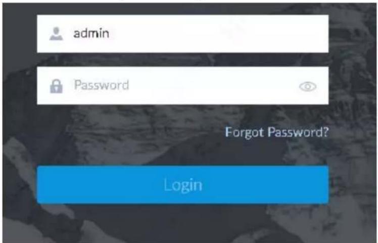
Step 2 Click Forgot Password?
Step 3 Click OK.
Step 4 Follow on-screen instructions to get security code and then enter the security code.
Figure 8-111 Security questions
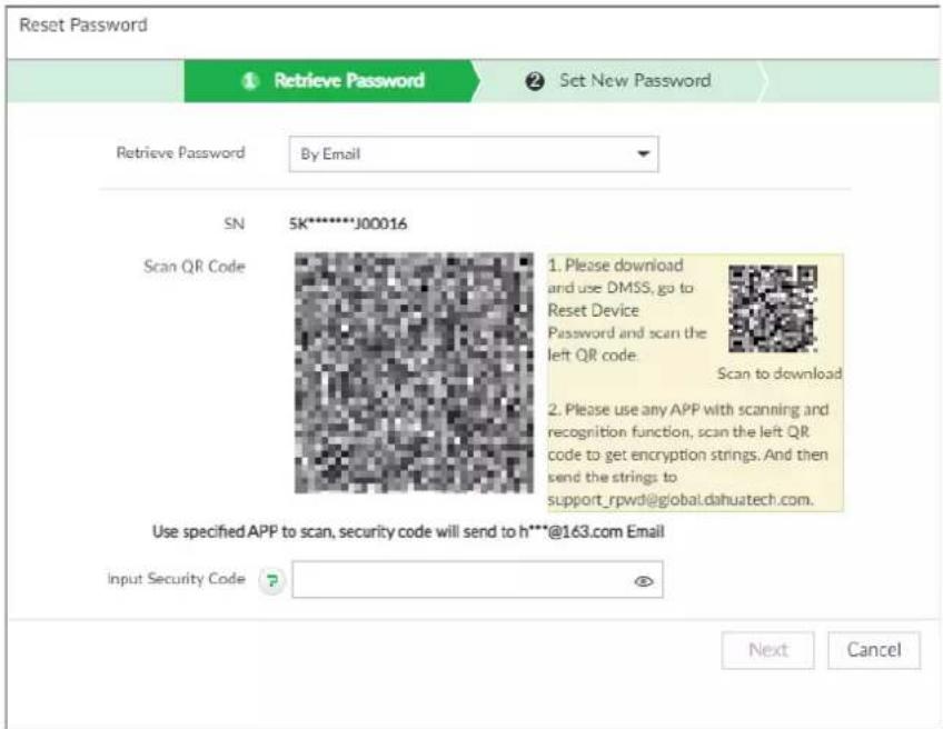
Step 5 Click Next.
Step 6 Set a new password.
Figure 8-112 New password setting
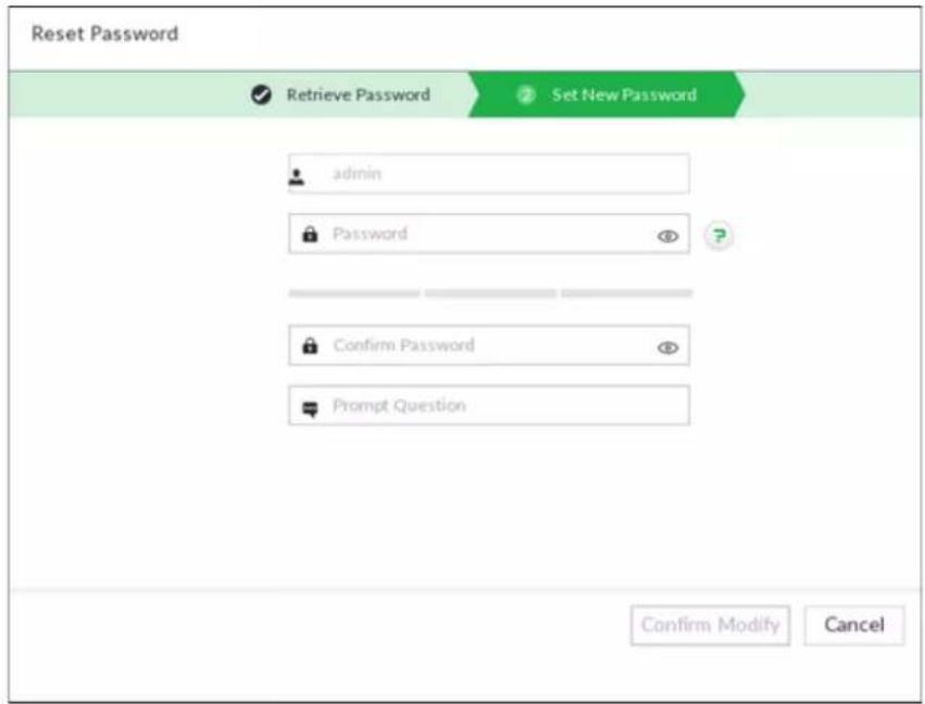
Table 8-37 Description of password parameters
| Parameters | Description |
| User The default username | is admin. |
| Password In the | New Password box, enter the new password and enter it again in the Confirm Password box.The password must consist of 8–32 non-blank characters and contain at least two types of the following characters: Uppercase, lowercase, numbers, and special characters (excluding '"; : &). Enter a strong password according to the password strength indication. |
| Confirm Password | |
| Prompt question | After setting the prompt, when you point to ☑ the login page, the system pops up a prompt to help you remember the password.The prompt question function is for local login only. See the actual page for detailed information. |
Step 7 Click Confirm Modify.
You can log in with the new password.
8.7.4 ONVIF
When the remote device is connecting with the device through ONVIF protocol, use the verified ONVIF account.

- System adopts three ONVIF user groups (admin, user and operator). You cannot add ONVIF user group manually.
- You cannot add user under ONVIF group directly.
8.7.4.1 Adding ONVIF User
Step 1 Click 🎨, or click + on the configuration page, and then select ACCOUNT.
Step 2 Select user group under ONVIF.
Figure 8-113 ONVIF
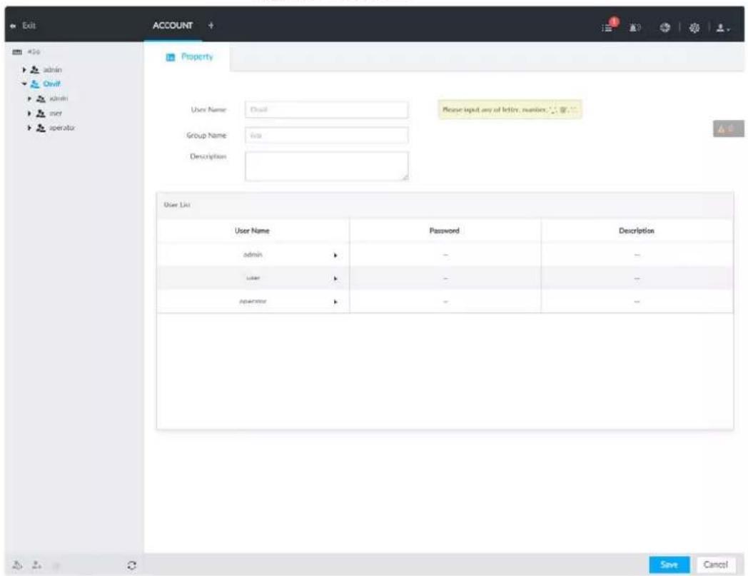
Step 3 Click 🙏 at the lower-left corner of the Property page.
Step 4 Enter the login password of current user, and then click OK.
Figure 8-114 ONVIF property
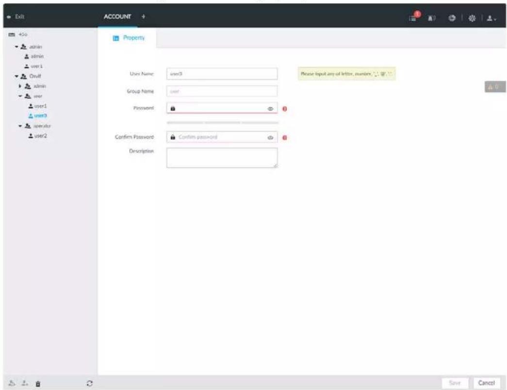
Step 5 Set parameters.
Table 8-38 ONVIF parameters description
| Parameters | Description |
| username | Set ONVIF username.The name ranges from 1 to 31 characters. It can contain English letters, number and special character (_ @ .). |
| Group name | Displays user organization node. System automatically identifies it. |
| Password | Set ONVIF user password.The password ranges from 8 to 32 non-empty characters. It can contain letters, numbers and special characters (excluding "";& and space) .The password shall contain at least two categories. Usually we recommend the strong password. |
| Confirm Password | |
| Description | Enter ONVIF user description information. |
Step 6 Click Save.
8.7.4.2 Deleting ONVIF User

Deleting the admin account is not supported.
Step 1 Click 🎨 or click + on the configuration page, and then select ACCOUNT.
Step 2 Select ONVIF and click .
Step 3 Enter current user's login password, and then click OK.
Step 4 Click OK.
8.8 System Configuration
Click 📍 or click + on the configuration page, select SYSTEM. The SYSTEM page is displayed. Set system basic settings, such as general parameters, time, display parameter, schedule, and voice.
Figure 8-115 System management

8.8.1 Setting System Parameters
Set system language, standard, user logout time, virtual keyboard, and mouse moving speed. Step 1 Click 🎨, or click + on the configuration page, and then select SYSTEM > General > System.
Figure 8-116 Configuring system settings
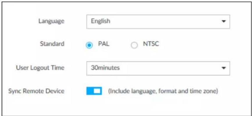
Step 2 Set parameters.
Table 8-39 System parameters description
| Parameters | Description |
| Language Set system language. | |
| Standard | Select video standard.PAL is mainly used in China, Middle East and Europe.NTSC is mainly used in Japan, United States of America, Canada and Mexico.[xxc8]As a technical standard of processing video and audio signals, PAL and NTSC mainly differ in encoding, decoding mode and field scanning frequency. |
| User Logout Time | Set auto logout interval once you remain inactive for a specified period or the device exceeds the set value. After auto logout, the user needs to login again to operate.If you select No Logout, system does not automatically log out. |
| Sync Remote Device | Click □ to enable the function. If enabled, the language, standard and time settings configured here will be synchronized to all the connected remote devices. |
| Virtual Keyboard | Enable virtual keyboard function on the local menu. See "Appendix 2.2 Virtual Keyboard" for detailed information. This function is for local menu only. This function is for local menu only. |
| Mouse Moving Speed | Set mouse moving speed on the local interface. This function is for local menu only. This function is for local menu only. |
Step 3 Click Save.
8.8.2 System Time
Set system time, and enable NTP function according to your need. After enabling NTP function, device can automatically synchronize time with the NTP server.
Step 1 Click 🎨 or click + on the configuration page, and then select SYSTEM > General > Time.
Figure 8-117 Time
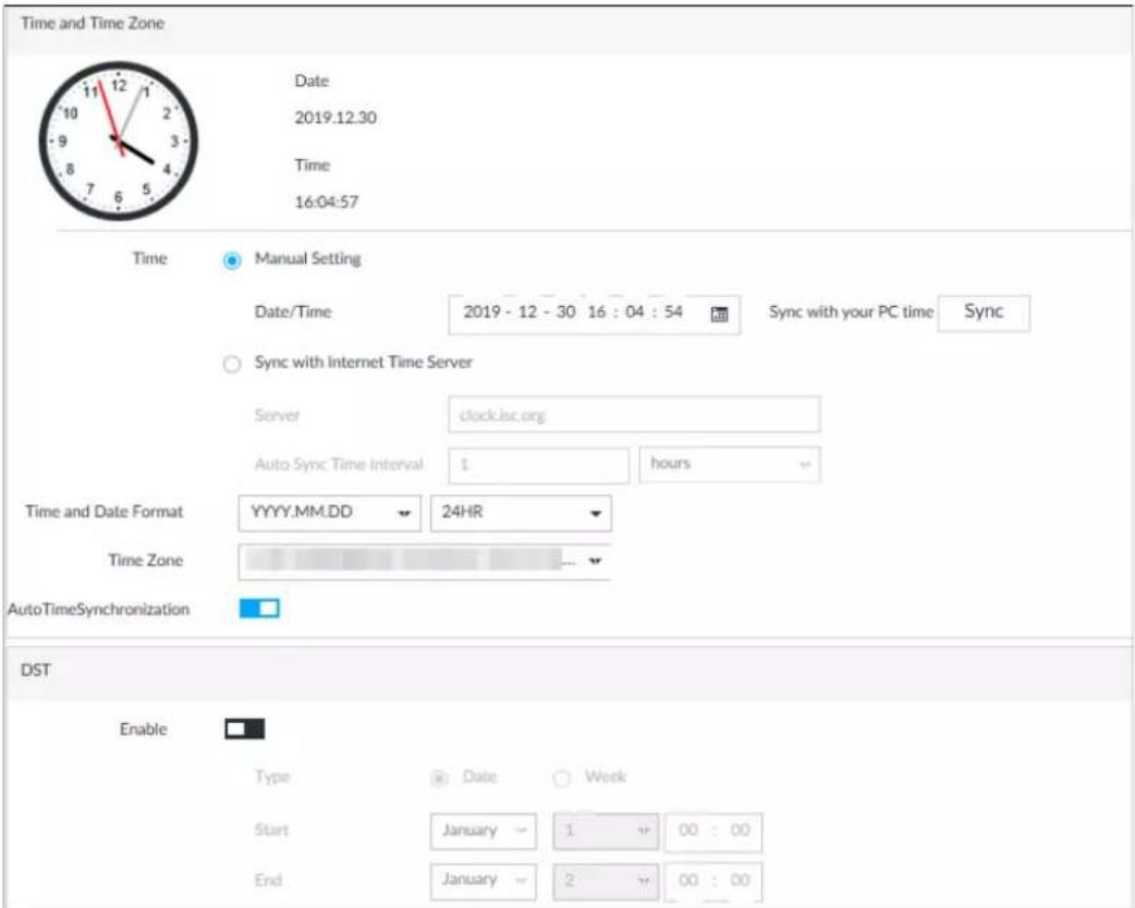
Step 2 Set parameters.
Table 8-40 System parameters description
| Parameters | Description |
| Time | Set system date and time. You can set manually or set device to synchronize time with the NTP server.Manual Setting: Select Manual Setting and then set the actual date and time in the following two ways.Click and then set the time and date in the calendar.Click Sync to synchronize device time with your PC.Sync with the Internet Time Server: Select the checkbox, enter NTP server IP address or domain, and then setAuto Sync Time Interval. |
| Time and Date Format | Set time and date display format. |
| Time Zone Set device time zone. | |
| Auto Time Synchronization | After enabling this function, IVSS detects system time of remote device once in every interval. When time of remote device is inconsistent with IVSS time, IVSS will calibrate the time of remote device automatically. |
Step 3 (Optional) Set DST.

DST is a system to stipulate local time, in order to save energy. If the country or region where the device is located follows DST, you can enable DST to ensure that system time is correct.
1) Click □ to enable DST.
2) Select DST mode. It includes Date and Week.
3) Set DST start time and end time.
Step 4 Click Save.
8.8.3 Display
Set connected display resolution and refresh rate.
Step 1 Click 🎨 or click + on the configuration page, and then select SYSTEM > General > Display.
Figure 8-118 Display
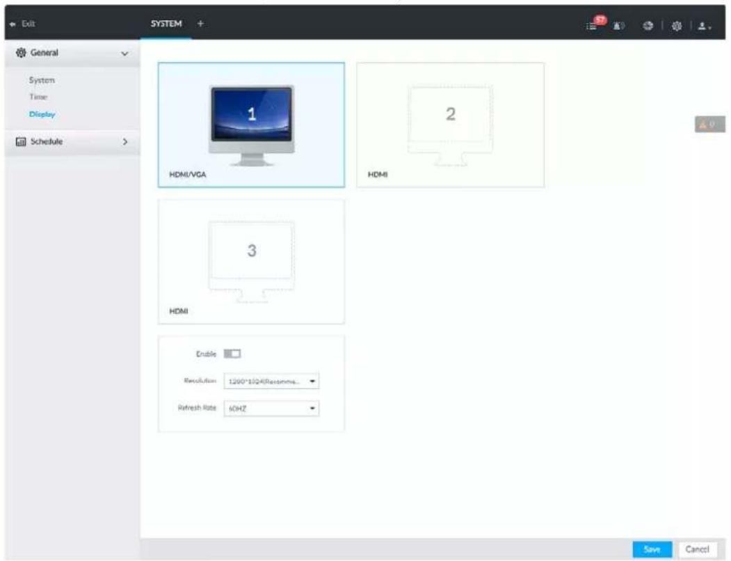

- SN 1–3 refers HDMI 1–HDMI 3. Among which, HDMI/VGA is the main display, while the VGA and HDMI 1 outputs the same video.
- VGA and HDMI 1 are outputting the same video source. Three HDMI ports can output different video sources.
- means display is connected and enabled. means display is connected but has not enabled. means display is disconnected.
Step 2 Select a display.
Step 3 Click □ to enable the selected display.
Step 4 Set parameters.
Table 8-41 Display parameters description
| Parameters | Description |
| Resolution | Set display resolution. Different displays support different resolutions. See your actual interface for detailed information. |
| Refresh rate | Set refresh rate of the display. |
Step 5 Click Save.
8.8.4 Schedule
Set schedule. When you are configuring alarm, record arm/disarm period, system can call the schedule directly. System only triggers the corresponding operations during the specified schedule.

Default schedule has been created by default. Default schedule is Always Effective, and cannot be modified or deleted.
Step 1 Click 🎨, or click + on the configuration page, and then select SYSTEM > Schedule > Schedule.
Figure 8-119 Schedule
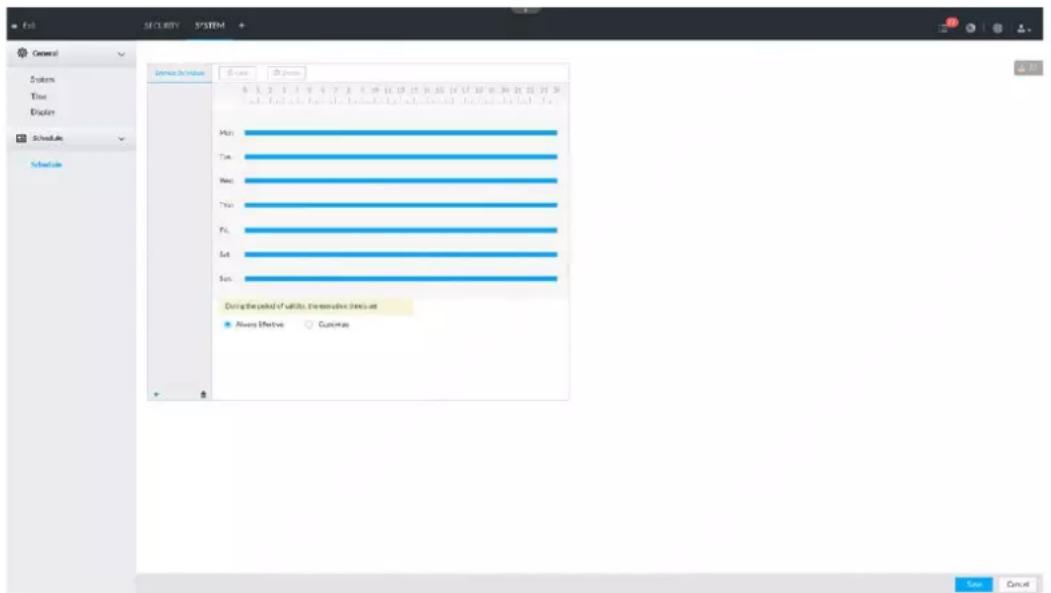
Step 2 Add schedule.
1) Click .+
2) Set schedule name.
3) Click OK to save the configuration.
Step 3 Set valid time period. It includes Always Effective and Customize.
Step 4 Set validity period of schedule.

- The step is for customized mode only.
• Each calendar supports maximum 50 validity periods. - The blue area on the time bar means the validity period.
On the time bar, you can:
- Click the blue area, and is displayed. Drag to adjust the start time and end time of validity period.
- Press the any blank space on the time bar, and drag to the right to add a validity period.
- Click Clear to clear all validity periods of current schedule.
- Select a validity period, and then click Delete to delete the period.
Step 5 Click Save.

Select an added schedule, and then click 🔒 to delete.
8.9 Cluster Service
The cluster function, also known as cluster redundancy, is a kind of deployment method that can improve the reliability of device. In the cluster system, there is a number of main devices and another number of sub devices (the N+M mode), and they have a virtual IP address (the cluster IP) for unified login and management. Under normal circumstances, the main devices are in the working state. When the main device fails, the corresponding sub device will take over the job automatically. When the main device recovers, the sub device will transmit the configuration data, cluster IP address and videos recorded during the failure to the main device which then takes over the job again.
In the N+M cluster system, there is a management server, the DCS (Dispatching Console) server, which is responsible for timely and correct scheduling management of the main and sub devices. When you create a cluster, the current IVSS is used as the first sub device and the DCS server by default.
8.9.1 Configuring Cluster
Create cluster, view cluster details, recover main devices and configure the arbitration IP address.
8.9.1.1 Creating a Cluster
Creating a cluster is to add multiple devices into a cluster that requires the addition of main and sub devices and the configuration of cluster IP.
When you create a cluster, the current Device is taken as the first sub device and the DCS server by default, and the priority of the other sub devices is determined by the order in which they are added, with the first sub device being the highest priority.
Figure 8-120 Procedure of creating a cluster
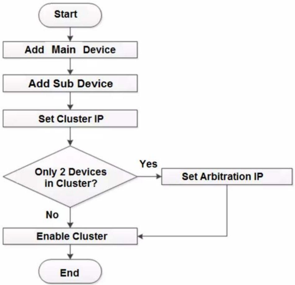
flowchart
graph TD
    A["Start"] --> B["Add Main Device"]
    B --> C["Add Sub Device"]
    C --> D["Set Cluster IP"]
    D --> E{Only 2 Devices in Cluster?}
    E -->|Yes| F["Set Arbitration IP"]
    F --> G["Enable Cluster"]
    G --> H["End"]
    E -->|No| I["End"]
Step 1 Click 📍 or click + on the configuration page, and then select CLUSTER SERVICE > CLUSTER.
Step 2 Add a main device or sub device.
1) Click Add.
Figure 8-121 Add cluster
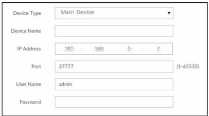
2) Set parameters.
Table 8-42 Parameters description
| Parameters | Description |
| Device Type | Select main device, or sub device as needed. |
| Device Name Name the device. | |
| IP Address | Enter the IP address of the main device or sub device.When adding the first sub device, you need not enter the IP address, because the first sub device is the current device by default. |
| Port 37777 by default. | |
| User Name | Username and password of the device, which are also used to log in to the web interface or PCAPP. |
| Password | |
3) Click OK.
Step 3 Click Start Cluster.

For a cluster of only 2 devices, you must set the arbitration IP address. For details. See "8.9.1.3 Configuring Arbitration IP".
Step 4 Set cluster IP address.

Cluster IP is a virtual IP that is used to access and manage the main devices and sub devices in the cluster. After logging in with the virtual IP, when the main device fails and the system is switched to the sub device, you can still view live video.
1) Click Cluster Setting.
Figure 8-122 Set cluster IP
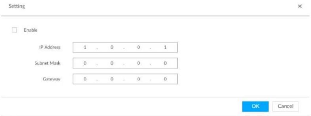
2) Select the Enable checkbox, and then set the other parameters as required.
3) Click OK.
8.9.1.2 Viewing Details
Click 🔒 that corresponds to a main or sub device to view device event logs including event time, name and details.
Figure 8-123 Event log
| Time | Name | Reason |
| 2019-10-23 09:19:30 | Connection failed. | Main connection failed. |
8.9.1.3 Configuring Arbitration IP
When there are only 2 devices in the cluster, a third-party device is required to determine whether the main device is faulty, so arbitration IP must be set for the cluster to perform a normal replacement operation. The arbitration IP can be the IP address of another device, PC or gateway that is connected to the device.
Step 1 Click ⚙, or click + on the configuration page, and then select CLUSTER SERVICE > CLUSTER.
Figure 8-124 Set arbitration IP
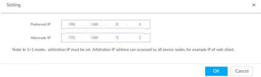
Step 3 Set the preferred IP and alternate IP.
Step 4 Click OK.
8.9.2 Record Synchronization
After the main device has recovered, the recordings on the sub device during the failure period need to be transmitted back to the main device.
Step 1 Click ⚙, or click + on the configuration page, and then select CLUSTER SERVICE > Record Transfer.
Step 2 Click Add.
Figure 8-125 Add
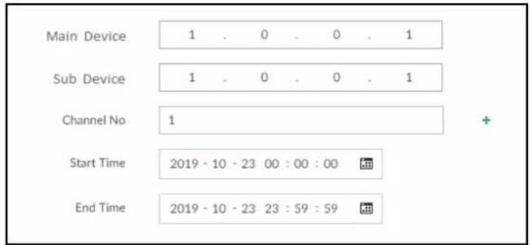
Step 3 Set parameters.
Table 8-43 Parameters
| Parameters | Description |
| Main Device Main device IP. | |
| Sub Device | Sub device IP. |
| Channel No. | Select the channel of which the video is to be transferred.Click to set the channel range. |
| Start Time | The start and end time of the video. |
| End Time | |
Step 4 Click OK.
8.9.3 Viewing Cluster Log
Step 1 Click ⚙, or click + on the configuration page, and then select CLUSTER SERVICE > Cluster Log.
Figure 8-126 Cluster log
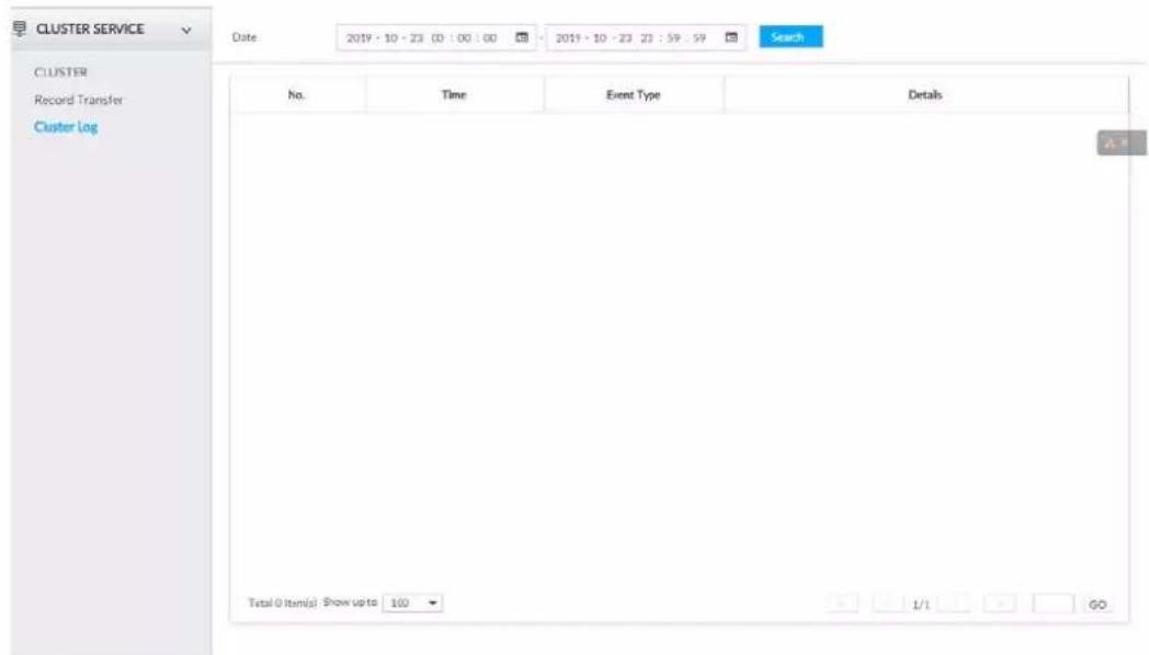
Step 2 Set search time, and then click Search.
The logs during the set time period are displayed.
9 System Maintenance
Click + on the LIVE page, and select MAINTAIN.
You can operate and maintain the device working environment to guarantee proper operation.
Figure 9-1 Maintain
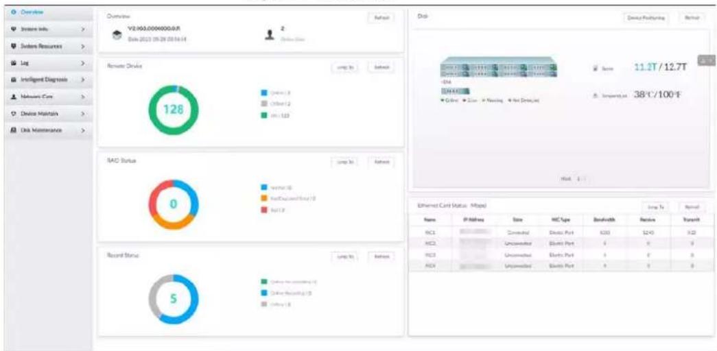
pie
| Category | Value | | :--- | :--- | | Remote Device | 128 | | BAD Status | 0 | | Record Status | 5 |9.1 Overview
Click + on the LIVE page, and select MAINTAIN > Overview.
Figure 9-2 Overview
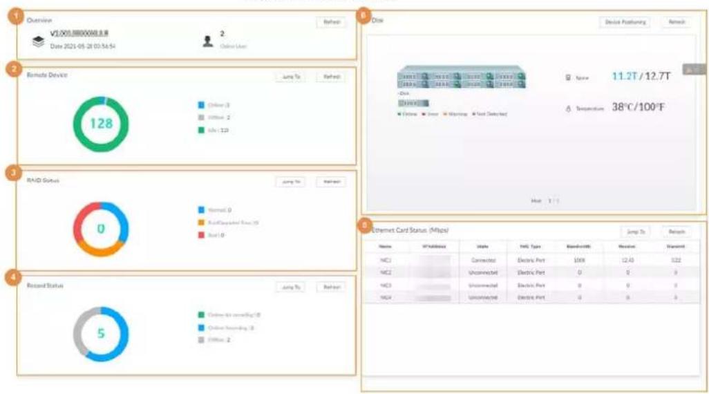
Table 9-1 Overview
| No. | Function | Description |
| 1 Overview | View device version details and online users.Click Refresh to refresh the data. | |
| 2 Remote Device | View the connection and idle status of remote devicesClick Jump To to go to the DEVICE page for detailed information.Click Refresh to refresh the data. | |
| 3 RAID Status | View RAID status.Click Jump To to go to the STORAGE page for detailed information.Click Refresh to refresh the data. | |
| 4 Record Status | View recording status of remote devices.Click Jump To to go to the VIDEO RECORDING page for detailed information.Click Refresh to refresh the data. | |
| 5 | Ethernet Card Status (Mbps) | View NIC status.Click Jump To to go to the TCP/IP page for detailed information.Click Refresh to refresh the data. |
| 6 Disk | View disk status, device temperature and storage usage.Click Device Positioning, and then the device positioning indicator flashes. In this way, you can quickly find the device.Click Refresh to refresh the data.indicates that the disk is online.indicates that the disk is in exception.indicates that the slot has no disk. |
9.2 System Information
9.2.1 Viewing Device Information
View device information such as input bandwidth, system version, and web version.
Click + on the LIVE page, and select MAINTAIN > System Info > Device Info.
Figure 9-3 Device info
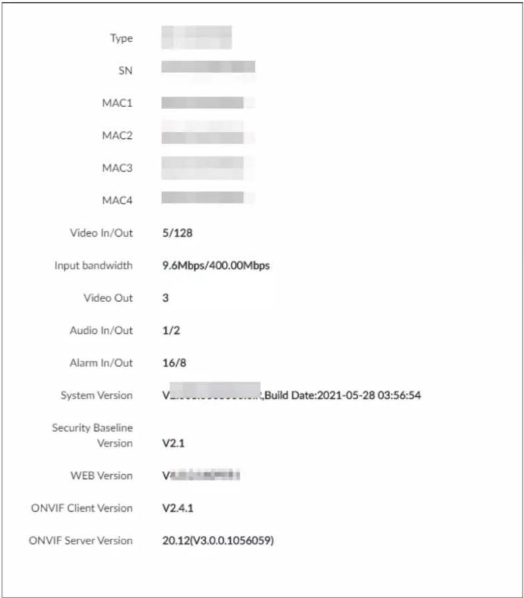
bar
| Category | Value | | :--- | :--- | | Type | 5/128 | | SN | 9.6Mbps/400.00Mbps | | MAC1 | 5/128 | | MAC2 | 5/128 | | MAC3 | 5/128 | | MAC4 | 5/128 | | Video In/Out | 5/128 | | Input bandwidth | 9.6Mbps/400.00Mbps | | Video Out | 3 | | Audio In/Out | 1/2 | | Alarm In/Out | 16/8 | | System Version | 20.00-27.00-33.00-34.00 (Build Date:2021-05-28 03:56:54) | | Security Baseline Version | V2.1 | | WEB Version | V2.1 | | ONVIF Client Version | V2.4.1 | | ONVIF Server Version | 20.12(V3.0.0.1056059) |9.2.2 Viewing Legal Information
View device software license, privacy policy, and open-source software note. Click + on the LIVE page, and select MAINTAIN > System Info > Legal Info.
9.2.3 Viewing Algorithm Version
View device algorithm license status and AI version information. Click 📄 in the LIVE page, and select MAINTAIN > System Info > Algorithm Version.
Figure 9-4 Algorithm version
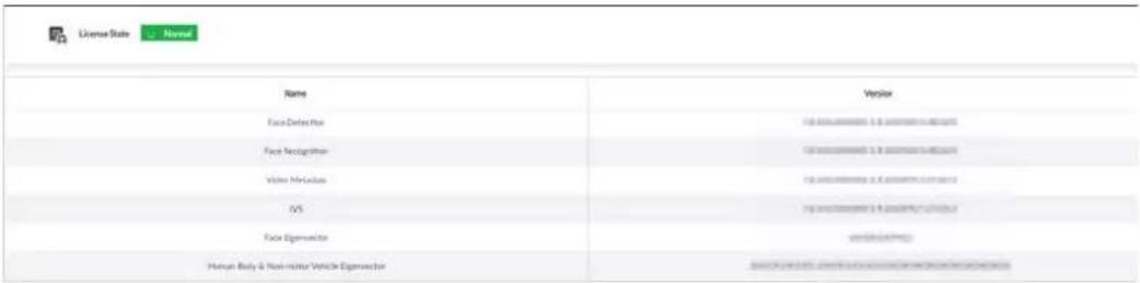
9.3 System Resources
View device and AI module information.
9.3.1 Viewing Device Resource
Click + on the LIVE page, and select MAINTAIN > System Resources > DEIVCE INFO.
The System Resources page is displayed. You can view resource status including CPU and memory usage, panel temperature and fan speed.
Figure 9-5 System resources
| Detection Item | Type | Value |
| Memory | Used Space/Total Space | 2.35GB/7.67GB |
| CPU | CPU Usage | 7% |
| MainboardFan1 | Fast Speed | 1090/Min |
| MainboardFan2 | Fast Speed | 18.2%/Min |
| Mainboard1 | Temperature | 42°C |
| Mainboard2 | Temperature | 333°C |
| Mainboard3 | Temperature | 22.75°C |
| Mainboard4 | Temperature | 34.19°C |
| CPU | Temperature | 20°C |
- Click ↗ to filter the search conditions.
- Click Refresh to refresh the data.
9.3.2 Viewing AI Module Information
Click + on the LIVE page, and select MAINTAIN > System Resources > AI Module Info. You can view status of the AI modules.
Figure 9-6 AI module information
9.4 Logs
The logs record all kinds of system running information. Check the log periodically and fix the problems in time to guarantee system proper operation.
9.4.1 Log Classification
Search system log, user log, event log, and link log.
Table 9-2 Log description
| Log | Type |
| System log | Search system log.It includes logs of system running status, file management, hot spare, hardware detect and scheduled task. |
| User operation log | Search user operation log.It includes user operation and user configuration log. |
| Event log | Search alarm event log.It includes logs of cross line detection, storage error, storage full, lock in, power fault, video motion, fan speed alarm, face detection, face recognition, human detect, device offline, tampering, no HDD, IPC offline, AI module offline, AI module temp, IO alarm, IP conflict, MAC conflict, and cross region detection. |
| Link log | Search device link log.You can search or export link log including user login/logout, session hijack, session blast and remote device. |
9.4.2 Log Search
The following steps are to search system log. See the actual page for detailed information.
Procedure
Step 1 On the LIVE page, click +, and select MAINTAIN > Log > System.
Step 2 Set search criteria such as system log level, type and date.
Step 3 Click Search.
Figure 9-7 System log
| Type | All | Level | All | Date | 2019 - 12 - 31 00:00 | 2019 - 12 - 31 00:00 | # |
| Description | |||||||
| Task Time | Notable | 2019-12-30 16:00:05 | OffTime (2019-12-30 13:39) / New Time (2019-12-30 16:00:00 P Address(75.35.5A): | ||||
| Task SystemTime | Notable | 2019-12-30 13:43:49 | OffTime (2019-12-30 15:46) / New Time (2019-12-30 15:46 P Address(75.35.5A): | ||||
| Task SystemTime | Notable | 2019-12-30 15:45:43 | OffTime (2019-12-30 15:46) / New Time (2019-12-30 15:46 P Address(75.35.5A): | ||||
| Task is posted | Notable | 2019-12-30 13:48:45 | Task Memorytime, 11 | ||||
| Task is posted | Notable | 2019-12-30 13:56:45 | Task Memorytime, 11 | ||||
| Task is posted | Notable | 2019-12-30 13:56:47 | Task Memorytime, 11 | ||||
| Task is posted | Notable | 2019-12-30 13:59:45 | Task Memorytime, 11 | ||||
| Task is posted | Notable | 2019-12-30 13:59:48 | Task Memorytime, 11 | ||||
| Task is posted | Notable | 2019-12-30 13:59:52 | Task Memorytime, 11 | ||||
| Task SystemTime | Notable | 2019-12-30 12:57:48 | OffTime (2019-12-30 12:57:48) / New Time (2019-12-30 12:57:48 P Address(75.35.5A): | ||||
| Starts | Error | 2019-12-30 12:55:33 | FlagSetPower all | ||||
| Absent | Error | 2019-12-30 12:55:33 | Tire (2019-0-30 12:56:35 | ||||
| Task SystemTime | Notable | 2019-12-30 12:47:48 | OffTime (2019-12-30 12:47:48) / New Time (2019-12-30 12:47:48 P Address(75.35.5A): | ||||
| Starts | Error | 2019-12-30 13:44:49 | FlagSetPower all | ||||
| Absent | Error | 2019-12-30 12:46:38 | Tire (2019-0-30 12:46:38) / New Time (2019-12-30 12:46:38 P Address(75.35.5A): | ||||
| Task SystemTime | Notable | 2019-12-30 09:53:39 | OffTime (2019-12-30 09:53:39) / New Time (2019-12-30 09:53:39 P Address(75.35.5A): | ||||
| Task SystemTime | Notable | 2019-12-30 14:00:55 | OffTime (2019-12-30 13:48:47) / New Time (2019-12-30 14:00:48) | ||||
Related Operations
Export and clear log.
Table 9-3 Log operation
| Name | Operation |
| Export log | Click and then the Export window appears. You can select whether to encrypt the exported log information.You need to set a password for export encryption. The password is required to unzip the exported file.If you export log in a non-encrypted way, log information will be exported to local PC or USB storage device without encryption. The log information might be overwritten when the disk space runs out.Back up in time. The log information might be overwritten when the disk space runs out.Back up in time. |
| Clear log | Click Clear all to clear all system logs.You will be unable to track the system error reason if you clear log. |
9.5 Intelligent Diagnosis
9.5.1 Run Log
View system running logs for troubleshooting.

Make sure that you have enabled Run Log in SECURITY > System Service. Otherwise there is no log data.
On the LIVE page, click + and select MAINTAIN > Intelligent Diagnosis > Run Log.
Figure 9-8 Logs
| ☐ (0) No. | Type | File Name | Operate |
| ☐ 1 | core | coredump/core-20191021142751@_IVSS2.000.0000002.0.R_172.12.1.101_123456789012345.gz | ↓ |
| ☐ 2 | core | coredump/core-20191021001805@_IVSS2.000.0000002.0.R_172.12.1.101_123456789012345.gz | ↓ |
| ☐ 3 | core | coredump/core-20191019220041@_IVSS2.000.0000002.0.R_172.12.1.101_123456789012345.gz | ↓ |
- Click to export a log.
- After selecting multiple logs, click Export to export them in batches.
9.5.2 One-click Export
Export the diagnosis data for troubleshooting when the device is in exception.
Step 1 On the LIVE page, click +, and select MAINTAIN > Intelligent Diagnosis > One-click Export.
Step 2 Click Generate Diagnosis Data to generate diagnosis data.
Step 3 Click Export to export the diagnosis result.
9.6 Network Care
9.6.1 Online User
Search for remote access network user information or you can block a user from access for a period of time. During the block period, the selected user cannot access the Device.

Cannot block yourself or block admin.
Step 1 On the LIVE page, click + and select MAINTAIN > Network Care > Online User. The Online User page is displayed.

The list displays the connected user information.
Step 2 Block user.
- Block: Click ⬤ corresponding to the user.
- Batch block: Select multiple users you want to block and then click Block.
The Block page is displayed.
Figure 9-9 Block
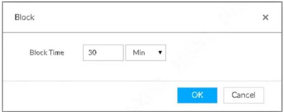
Step 3 Set block period. The default period is 30 minutes.
Step 4 Click OK to save the configuration.
9.6.2 Packet Capture
Packet capture is the practice of intercepting a data packet that is crossing or moving over a specific computer network. The captured packet is stored temporarily for analysis. The packet is inspected to help diagnose and solve network problems and determine whether its structure follows network security policies.
Step 1 On the LIVE page, click +, and select MAINTAIN > Network Care > Packet Capture.
Figure 9-10 Packet capture
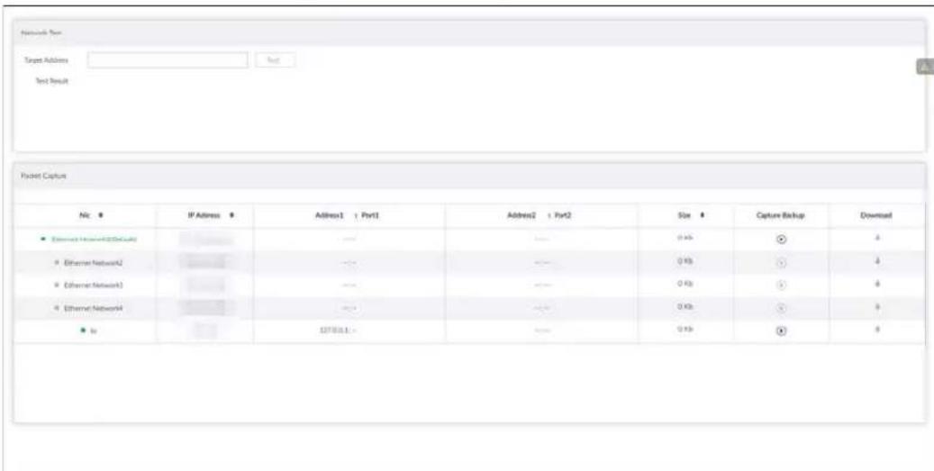
Step 2 In the Network Test section, enter the target address, and then click Test.
After testing is completed, the test result is displayed. You can check the evaluation for average delay, packet loss, and network status.
Step 3 (Optional) When operating on the local interface, connect a USB storage device to the Device, select the USB device, and then click Browse to select the saving path.
Step 4 In the Packet Capture section, click to start capturing the packets of the corresponding NIC, and then click no stop.

- You cannot capture packets of several NICs at the same time.
- During packet capturing, you can go to other pages for operation and go back to the
Packet Capture page later to stop packet capturing.
Step 5 (Optional) When operating on the web or PCAPP, click ↓ to download the captured packet.
9.7 Device Maintenance
Device maintenance is to reboot device, restore factory default setup, or upgrade system and so on. It is to clear the malfunction or error during the system operation and enhance device running performance.
9.7.1 Updating Device
Update device or the AI module version.
9.7.1.1 Updating the Device
You can import the update file to update device version. The update file extension name shall be .bin.

- During update, do not disconnect from power and network, and reboot or shut down the Device.
- Make sure that the update file is correct. Improper update file might result in device error!
You need to obtain the correct update file and save it in the corresponding path. - When operating on the local interface, save the update file in the USB storage device and then connect the USB storage device to the IVSS.
- When operating on the web or PCAPP interface, save the update file on the PC in which the web or PCAPP is located.
Step 1 On the LIVE page, click +, and select MAINTAIN > Device Maintain > Update > Host.
Step 2 Click Browse to select an update file.
Step 3 Click Upgrade Now.
Step 4 Click OK.
The system starts updating. Device automatically restarts after successfully updated.
9.7.1.2 Updating AI Module
You can import the update file to update AI module. The update file extension name shall be .bin.

- During update, do not disconnect from power and network, and reboot or shut down the Device.
- Make sure that the update file is correct. Improper update file might result in device error!
You need to obtain the correct update file and save it in the corresponding path.
- When operating on the local interface, save the update file in the USB storage device and then connect the USB storage device to the IVSS.
- When operating on the web or PCAPP interface, save the update file on the PC in which the Web or PCAPP is located.
Step 1 On the LIVE page, click + and select MAINTAIN > Device Maintain > Update > AI Module.
Step 2 Click File upgrade.
Step 3 Click Browse to select an update file.
Step 4 Click Upgrade Now.
Step 5 Click OK.
The system starts updating. Device automatically restarts after successfully updated.
9.7.1.3 Updating Cameras
You can import the update file to update cameras. The update file extension name shall be .bin.

- During update, do not disconnect from power and network, and reboot or shut down the Device.
- Make sure that the update file is correct. Improper update file might result in device error!
You need to obtain the correct update file and save it in the corresponding path.
- When operating on the local interface, save the update file in the USB storage device and then connect the USB storage device to the IVSS.
- When operating on the web or PCAPP interface, save the update file on the PC in which the Web or PCAPP is located.
Step 1 On the LIVE page, click +, and select MAINTAIN > Device Maintain > Update > Camera Update.
Step 2 Select one or more cameras and then click File upgrade.

Stop recording before update. If you are updating a camera that is recording, the following prompt will pop up.
Figure 9-11 Prompt
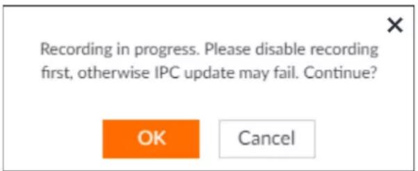
Step 3 Click Browse to select an update file.
Step 4 Click Upgrade Now.
Step 5 Click OK.
9.7.2 Default
When the system runs slowly and has configuration errors, try to solve the problems by restoring the default settings.

All configurations are lost after factory default operation.
Step 1 On the LIVE page, click +, and then select MAINTAIN > Device Maintain > Default.
Figure 9-12 Default
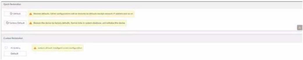
Step 2 Select a method between Quick Restoration and Custom Restoration.
Step 3 Click OK.
System begins to restore default settings. After successfully restored default settings, system prompts to restart the device.
9.7.3 Automatic Maintenance
If the device has run for a long time, you can set to automatically reboot the device at idle time.
Step 1 On the LIVE page, click +, and then select MAINTAIN > Device Maintain > Auto Maintain.
Figure 9-13 Auto Maintain

Step 2 Set auto reboot time.
Step 3 Click Save.
Step 4 Enable Emergency Maintenance.
When the Device has an upgrade power outage, running error and other problems, and you cannot log in, you can enable Emergency Maintenance to restart, clear configuration, and upgrade.
Figure 9-14 Emergency Maintenance

9.7.4 IMP/EXP
Export device configuration file to local PC or USB storage device, to backup it. When the configuration is lost due to abnormal operation, import the backup configuration file to restore system configurations quickly.
On the LIVE page, click +, and then select MAINTAIN > Device Maintain > IMP/EXP. The IMP/EXP page is displayed.
Figure 9-15 IMP/EXP

Exporting Configuration File
Click Export to export configuration file to local PC or USB storage device. File path might vary depending on your operations.
- On PCAPP, click, select Download to view file saving path.
- Select file saving path during local operation.

Connect USB device to the system if you are on the local menu to operate.
- During web operations, files are saved under default downloading path of the browser.
Importing Configuration File
Click Browse to select the configuration file, and then click Import. After the configuration file is imported successfully, the device will reboot automatically.
9.8 Disk Maintenance
Check the HDD status to handle exceptions in time.
9.8.1 S.M.A.R.T Detection
Run S.M.A.R.T detection to check HDD status.
Step 1 On the LIVE page, click + and select MAINTAIN > Disk Maintain > S.M.A.R.T Detection.
Figure 9-16 S.M.A.R.T detection
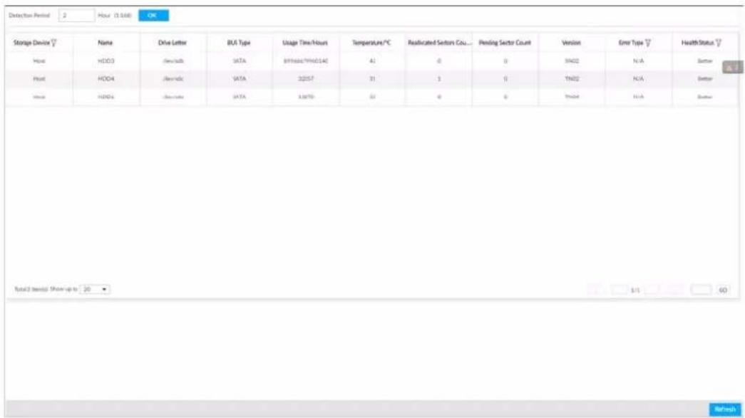
Step 2 Set the detection period.
Step 3 Click OK.
9.8.2 SSD Health Detection
On the LIVE page, click +, and select MAINTAIN > Disk Maintain > SSD Health Detection, and then you can view the storage allocation and remaining P/E cycle of SSD.
Figure 9-17 SSD health detection
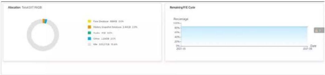
pie
| Category | Percentage (%) | |---|---| | Pure Database | 100 | | History Snapshot Database | 244GB | | Apache HCP | 80 | | Other | 134GB | | Kmr | 1037GB | | Remaining P/E Cycle (Date) | 6.7 |9.8.3 Firmware Update
Import update file to update HDD information.
Step 1 On the LIVE page, click +, and select MAINTAIN > Disk Maintain > Firmware Update.
Figure 9-18 Firmware update
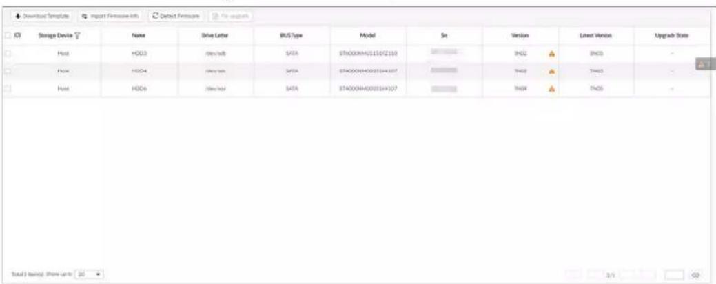
Step 2 Click Download Template to download update template
Step 3 Click ≡, select Download, and then open and fill in the downloaded template.
Step 4 Select an HDD, click Import Firmware Info, click Browse to choose the template to be imported, and then click Import.
Step 5 Click Firmware Update to update firmware information.
Step 6 Click Detect Firmware to refresh firmware information displayed on the page.
10 PCAPP Introduction
After installing PCAPP, system supports to access the Device remotely to carry out system configuration, function operations and system maintenance.

For details about installing PCAPP, see "5.3.1 Logging in to PCAPP Client".
10.1 Page Description
Double-click on the PC desktop.
Figure 10-1 Task column

Table 10-1 Icons
| Icons | Description |
| PCAPP Please Enter URL | Address bar: Enter the IP address of remote device. |
| → | Enter device IP address and then click the button to go to the login page.Now the icon turns intoClick to refresh the page. |
| ≡ | Click to view history login record, view downloads, set compatibility mode and view device version information. |
| - | Click to minimize PCAPP. |
| ☐ | Click to maximize PCAPP. |
| ### | Click to display PCAPP at full screen. |
| × | Click to close PCAPP. |
10.2 History Record
Click ≡, and then select History.
You can view history access record and clear buffer.
- Click Clear History to clear all history records.
- Click Clear Buffer to clear buffer data, and reboot PCAPP.
10.3 Viewing Downloads
To view and clear history downloads, click ≡, and then select Download. The Downloads page is displayed.
- Double-click file name to open it.
- Click Displayed in Folder to open the folder where the file is located.
- Click Clear Downloads to clear history download records.
10.4 Configuring PCAPP
When PC theme is not Areo, video of PCAPP might not be displayed normally. It is suggested that PC theme should be switched to Areo, or compatibility mode of PCAPP should be enabled.
Switching PC Theme

This section uses Windows 7 as an example.
Right-click any blank position on PC desktop, select Personalize, and then switch to Aero theme. Restart PCAPP before the Aero theme takes effect.
Figure 10-2 PC theme
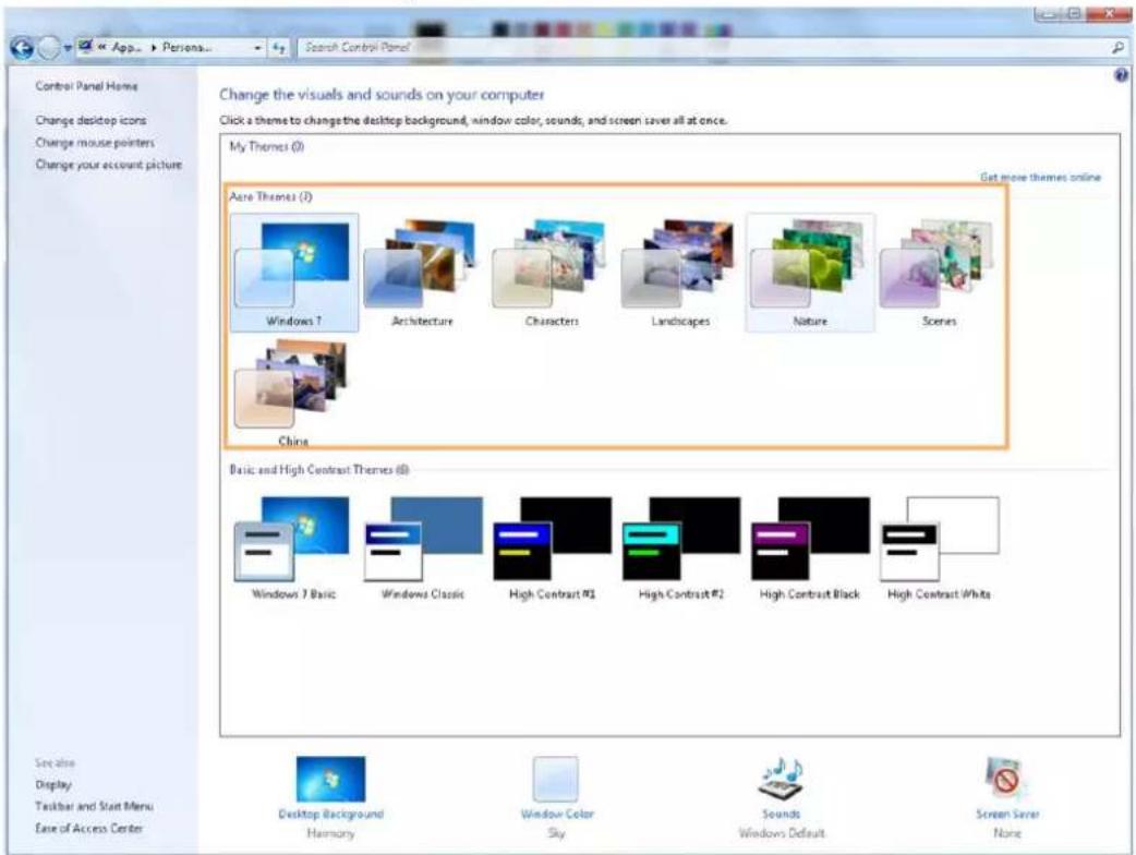
Setting Video and Picture Storage Path
Click Browse to specify the paths for saving videos and pictures. Only PCAPP supports this function.
Enabling Compatibility Mode
Click ≡, and select Settings. The Settings page is displayed. Select compatibility mode. Restart PCAPP before the compatibility mode takes effect.
Figure 10-3 Setting
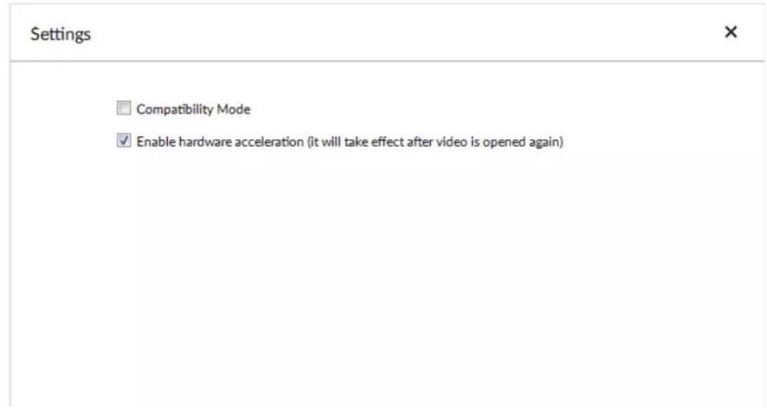
Enabling Hardware Acceleration
Click ≡, and select Settings. Select Enable hardware acceleration (it will take effect after video is opened again).
The live view becomes much more fluent when this function is enabled.
10.5 Viewing Version Details
Click ≡ and then select About to view PCAPP version information.
11 Log Out, Reboot, Shut Down, Lock
Log out, reboot, shut down and lock out the Device.
Figure 11-1 User operation
| Hi, admin | |
| ← | Change Password |
| 💡 | Lock |
| → | Log Out |
| ☀️ | Reboot |
| 💡 | Shut Down |
Logging Out
Click 📁 and then select Log Out.
Rebooting
Click 📁, and then select Reboot. System pops up confirm dialogue box. Click OK to reboot.
Shutting Down

To unplug the power cable might result in data (record and image) loss.
- Mode 1 (recommended): Click, and then select Shutdown. System pops up confirm dialogue box and then click OK to shut down.
- Mode 2: Use power on-off button on the device.
◇ 8-HDD series product: Press power on-off button on rear panel.
- Other series products: Press the power on-off button on the device for at least 4 seconds.
- Mode 3: Unplug the power cable.
Locking
Click 📁 and then select Lock to lock the client. The locked client cannot be operated.
To unlock the client, click anywhere on the client, and then the Unlock dialogue box is displayed. Enter the username and password, and then click OK. You can also click Switch User to switch to another user account.
Figure 11-2 Unlock the client
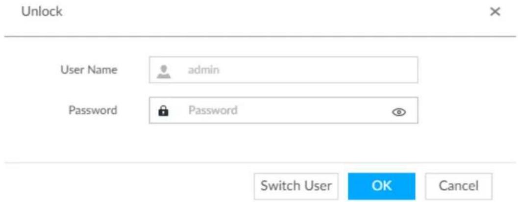
12 FAQ
| Problem | Possibilities and Solutions |
| After enabling AI by device function, there is no human face recognition event. | The AI module is offline.Click on the LIVE page, and select MAINTAIN > System Resources > AI Module Info. You can view status of the AI modules.There are too many filter criteria on the AI display page.The registered remote device does not support face detection function.Enable AI by device function. See "6.2.2 Configuring Face Detection" for detailed information.It is not in the deployment period.There is no linked face database or the face database has no data.The human face similarity setting is too high. |
| After enabling AI by camera function, there is no human face recognition event. | The human face recognition function has not been enabled on the AI plan.There is no human face database on the web interface of the remote device.It is not in the deployment period. |
| There are no human face search results. | The human face similarity setting is too high.The selected remote device does not trigger the human face recognition.There is no human face recognition on the search period.The specified human face image is not on the human face database. |
Appendix 1 Glossary
| Name | Description |
| CGI | Common Gateway Interface (CGI) is an important Internet technology. With CGI, client can ask data from program running on network server. CGI describes data transmission standard between server and asking processing program. |
| DDNS | Dynamic Domain Name System (DDNS) is to map the user dynamic IP address to a specified domain analysis service. Each time, when the user connects to the network, the client can transmit the host dynamic address to the server application on the host of the service provider. The server applications are to provide the DNS service and realize dynamic domain analysis. That is to say, the user does not need to remember the changeable IP address, just uses the domain name to login the device or the address. |
| DHCP | Dynamic Host Configuration Protocol (DHCP) is a network protocol in the LAN. It is to automatically allocate IP address for the internal network or the ISP (Internet service provider).It is to manage the computer IP address by the unified means of management. |
| DNS | Domain Name System (DNS) is to save the all host domain name and corresponding IP address in the network. It has the ability to change the domain to the IP address. |
| DVR Digital Video Recorder. | |
| FTP | File Transfer Protocol (FTP) is used to control bilateral transmission of file on the Internet. |
| HDMI | High Definition Multimedia Interface (HDMI) is a special digital interface suitable for audio/video transmission. It can transmit audio signal and video signal at the same time. |
| HTTPS | Hyper Text Transfer Protocol over Secure Socket Layer (HTTPS) is a HTTP channel for security purpose. The HTTPS has defined the browser the world wide web service safety communication rule. It adopts encryption technology to guaranty safety access to the webpage. |
| IP Internet Protocol. | |
| IPC IP Camera. | |
| NTP | Network Time Protocol (NTP) is a protocol to synchronize computer time. It adopts wireless network protocol UDP, so that the computer time synchronizes with the server or the time source. It is to provide time correction of high accuracy. |
| NTSC | National Television Standards Committee, American national standard television and broadcast transmission and receiving protocol. This is a television standard that television scanning beam is 525 beams, 30 frames per second, interlaced scanning, odd field first and then it is followed by even field. NTSC is used in the United States of America, Japan, and so on. |
| NVR Network Video Recorder | |
| MTU | Maximum Transmission Unit (MTU) refers to the maximum data packet amount (byte) on one layer of the communication protocol. |
| ONVIF | Open Network Video Interface Forum (ONVIF) is the defined general protocol for information exchange among the network video devices. It includes search device, real-time audio/video, metadata, information control, and so on. |
| PAL | Phase Alteration Line, this is a television standard that television scanning beam is 625 beams, 25 frames per second, phase alteration, odd field first and then it is followed by even field. PAL color encoding is used. PAL is used in China, Europe, and so on. |
| PTZ | Pan Tilt Zoom (PTZ) refers to the PTZ all-direction movement, lens zoom, and focus control. |
| RAID | RAID is an abbreviation for Redundant Array of Independent Disks. It is to combine several independent HDDs (physical HDD) to form a HDD group (logic HDD), to provide higher storage performance and data redundancy. |
| S.M.A.R.T | Self-Monitoring Analysis and Reporting Technology (S.M.A.R.T) is a technical standard to detect HDD drive status and report potential problems. |
| SSH | Secure Shell (SSH) is a security protocol formulated by IETF network group on the basis of application layer. SSH protocol can effectively prevent information leakage problem during remote management. |
| SVC | Scalable Video Coding (SVC) is a video encoding technology. It can split the video streams to one basic layer and several enhanced layers according to the requirements. The basic layer provides the general video quality, frame rate and resolution, and the enhanced layer is to perfect the video quality. |
| VGA | Video Graphics Array (VGA) is a video transmission standard. It has high resolution, high display speed and abundant colors. |
| WLAN | Wireless Local Area Networks (WLAN) adopts radio frequency to realize data transmission. |
Appendix 2 Mouse and Keyboard Operations
This section introduces mouse and keyboard operations.
Appendix 2.1 Mouse Operations
Connect mouse to the USB port, you can use the mouse to control the local menu. For details, see the following table.
Appendix Table 2-1 Mouse operations
| Operation | Description |
| Click (click the left mouse button) | Click to select a function menu, to enter the corresponding menu page.Implement the operation indicated on the control.Change checkbox and option button status.Click the checkbox to display drop-down list.On virtual keyboard, select letter, symbol, English upper letter and lower letter, and Chinese characters. |
| Double-click (click the left mouse button twice) | On the LIVE page, double-click one video window to zoom in the window. Click any position out of the window, so the video window restores original size.On the LIVE page, double-click the remote device in the device tree. Switch to video edit status, and add remote device.Double-click the image or record file thumbnail, to playback record file or view the image. |
| Right-click (click the right mouse button) | On the LIVE or SEARCH page, right-click one video window to display the shortcut menu.On the LIVE page, right-click the view in the list or the remote device in the device tree, to display the shortcut menu. |
| Wheel button | On the SEARCH page, mpoint to the time bar, and then click the mouse wheel, to adjust the accurate time on the time bar.Click the control that needs to input number (such as input date or time). Roll the mouse wheel to adjust the number value. |
| Drag the mouse | Drag the mouse pointer to select the motion detect zone.On the LIVE page, drag the remote device in the device tree to the play window, switch to the view status. It is to add the remote device.On the SEARCH page, drag the record file or the image thumbnail to the playback window. It is to play back the corresponding record file or image. |
Appendix 2.2 Virtual Keyboard
The local menu supports virtual keyboard.
Click the text box to display virtual keyboard. For details, see the following pictures and table.

If the device has connected to the peripheral keyboard, click the text column. Virtual keyboard will disappear.
Appendix Figure 2-1 Virtual keyboard (global keyboard)
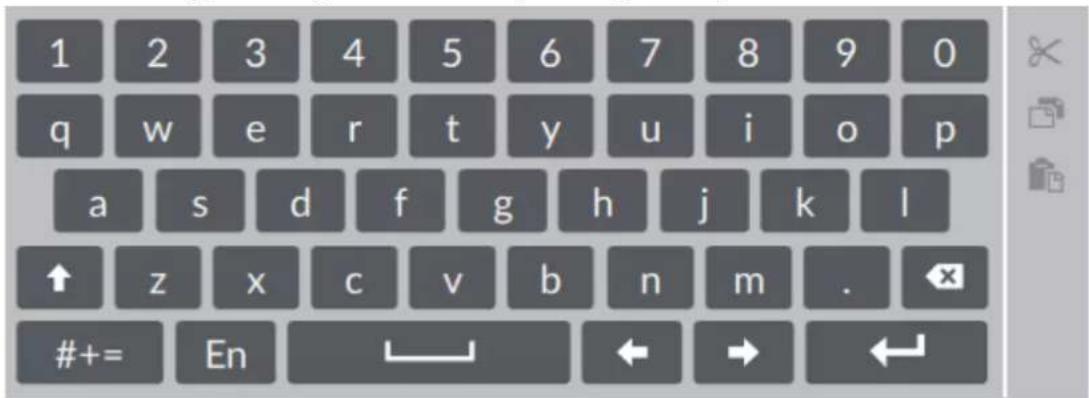
Appendix Figure 2-2 Virtual keyboard (digital keyboard)
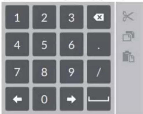
Appendix Figure 2-3 Virtual keyboard (input letter)
![[ ] { } # % ^ * + = _ \ | ~ < > @ $ & rtsp ` " ; / : - ( ) // com . , ? ! ' abc En ← → ←](/content/2026/05/1061580/images/3e3fe3e6158c4a44f66ac1d21cbd2aae9b407083caebcbd9615655b08b2cc20d.jpg)
Appendix Table 2-2 Virtual keyboard icon
| Signal Words | Description |
| Click the icon to switch to upper case. The icon becomes ↑. Click ↑ to switch to lower case. | |
| [300T] | Click to delete letter. |
 | Click to input letter. Now the icon turns intoabc. Clickabcto restore previous input mode. |
| [Model] | Click to input space. |
| [Model]click to control cursor position. | |
| [Model] | Click to switch to the next line. |
| [Model] | Select text and click the icon to cut the selected contents. |
| [Model] | Select text and click the icon to copy the selected contents. |
| [Model] | Cut or copy the contents, click the text box and click the icon to paste the contents. |
Appendix 3 RAID
RAID is an abbreviation for Redundant Array of Independent Disks. It is to combine several independent HDDs (physical HDD) to form a HDD group (logic HDD).
Comparing with one HDD, RAID provides more storage capacity and data redundancy. The different redundant arrays have different RAID level. Each RAID level has its own data protection, data availability and performance degree.
RAID Level
| RAID Level | Description | Min. HDD Needed |
| RAID0 | RAID 0 is called striping.RAID 0 is to save the continued data fragmentation on several HDDs. It can process the read and write at the same time, so its read/write speed is N (N refers to the HDD amount of the RAID 0) times as many as one HDD. RAID 0 does not have data redundant, so one HDD damage might result in data loss that cannot be restored. | 2 |
| RAID1 | It is also called mirror or mirroring.RAID 1 data is written to two HDDs equally, which guarantee the system reliability and can be repaired. RAID 1 read speed is almost close to the total volume of all HDDs. The write speed is limited by the slowest HDD. At the same time, the RAID 1 has the lowest HDD usage rate. It is only 50%. | |
| RAID5 | RAID5 is to save the data and the corresponding odd/even verification information to each HDD of the RAID5 group and save the verification information and corresponding data to different HDDs. When one HDD of the RAID5 is damaged, system can use the rest data and corresponding verification information to restore the damaged data. It does not affect data integrity. | 3 |
| RAID6 | Based on the RAID5, RAID6 adds one odd/even verification HDD. The two independent odd/even systems adopt different algorithm, the data reliability is very high. Even two HDDs are broken at the same time, there is no data loss risk.Comparing to RAID5, the RAID6 needs to allocate larger HDD space for odd/even verification information, so its read/write is even worse. | 4 |
| RAID10 | RAID 10 is a combination of the RAID 1 and RAID 0. It uses the extra high speed efficient of the RAID 0 and high data protection and restores capability of the RAID 1. It has high read/write performance and security. However, the RAID 10 HDD usage efficiency is as low as RAID 1. | |
| RAID50 | RAID50 is a combination of the RAID5 and RAID0. It has higher fault-tolerance. There is no data loss even one HDD in the set malfunctions. | 6 |
| RAID60 | RAID60 is a combination of the RAID6 and RAID0. It has higher fault-tolerance and read performance. There is no data loss even two HDDs in one set malfunctions. | 8 |
RAID Capacity
See the sheet for RAID space information.
Capacity N refers to the mini HDD amount to create the corresponding RAID.
| RAID Level | Total Space of the N HDD |
| RAID0 The total amount of current RAID group | |
| RAID1 Min (capacity N) | |
| RAID5 (N-1) ×min (capacity N) | |
| RAID6 (N-2) ×min (capacityN) | |
| RAID10 (N/2)×min (capacityN) | |
| RAID50 (N-2) ×min (capacity N) | |
| RAID60 (N-4) ×min (capacity N) | |
Appendix 4 HDD Capacity Calculation
HDD capacity calculation formula:
Total capacity (M) = Channel number × Demand time length (hour) × HDD capacity occupied per hour (M/hour)
According to the above formula, get recording time calculation formula.
Recording time (hour) =
Total capacity (M)
HDD capacity occupied per hour (M/hour)×Channelnumbner
For example, for single-channel recording, HDD capacity occupied per hour is 200 M/hour. Use 4-channel device to make 24-hour continuous recording in every day of one month (30 days), the required HDD space is: 4 channels×30 days×24 hours×200 M/hour = 576 G. Therefore, five 120 G HDD or four 160 G HDD shall be installed.
According to the above formula, at different stream values, recording file size of 1 channel in 1 hour is shown as follows (for your reference):
Appendix Table 4-1 HDD capacity calculation
| Bit stream Size (max.) | File Size | Bit Stream Size (max.) | File Size |
| ≤ 96 K | 42 M | 128 K | 56 M |
| 160 K | 70 M | 192 K | 84 M |
| 224 K | 98 M | 256 K | 112 M |
| 320 K | 140 M | 384 K | 168 M |
| 448 K | 196 M | 512 K | 225 M |
| 640 K | 281 M | 768 K | 337 M |
| 896 K | 393 M | 1024 K | 450 M |
| 1280 K | 562 M | 1536 K | 675 M |
| 1792 K | 787 M | 2048 K | 900 M |
Appendix 5 Particulate and Gaseous Contamination Specifications
Appendix 5.1 Particulate Contamination Specifications
The following table defines the limitations of the particulate contamination in the operating environment of the device. If the level of particulate contamination exceeds the specified limitations and result in device damage or failure, you need to rectify the environmental conditions.
Appendix Table 5-1 Particulate contamination specifications
| Particulate contamination | Specifications |
| Air filtration | Class 8 as defined by ISO 14644-1. |
| Conductive dust | Air must be free of conductive dust, zinc whiskers, or other conductive particles. |
| Corrosive dust | Air must be free of corrosive dust. Residual dust present in the air must have a deliquescent point less than 60% relative humidity. |
Appendix Table 5-2 ISO 14644-1 cleanroom classification
| Class | Maximum particles/ m^3 | |||||
| — | ≥0.1 μm | ≥0.2 μm | ≥0.3 μm | ≥0.5 μm | ≥1 μm | ≥5 μm |
| Class 1 10 2 | — — — — | |||||
| Class 2 | 100 | 24 | 10 | 4 | — | — |
| Class 3 | 1000 | 237 | 102 | 35 | 8 | -7 |
| Class 4 | 10000 | 2370 | 1020 | 352 | 83 | — |
| Class 5 | 100000 | 23700 | 10200 | 3520 | 832 | 29 |
| Class 6 | 1000000 | 237000 | 102000 | 35200 | 8320 | 293 |
| Class 7 | — | — | — | 352000 | 83200 | 2930 |
| Class 8 | — | — | — | 3520000 | 832000 | 29300 |
| Class 9 | — | — | — | — | 8320000 | 293000 |
Appendix 5.2 Gaseous Contamination Specifications
Usually indoor and outdoor atmospheric environments contain a small amount of common corrosive gas pollutants. When these mixed or single corrosive gas pollutants react with other environmental factors such as temperature or relative humidity in the long term, the device might suffer from a risk of corrosion and failure. The following table defines the limitations of the gaseous contamination in the operating environment of the device.
Appendix Table 5-3 Gaseous contamination specifications
| Gaseous contamination | Specifications |
| Copper coupon corrosion rate | < 300 Å/month per Class G1 as defined by ANSI/ISA71.04-2013 |
| Silver coupon corrosion rate | < 200 Å/month per Class G1 as defined by ANSI/ISA71.04-2013 |
Appendix Table 5-4 ANSI/ISA-71.04-2013 classification of reactive environments
| Class | Copper Reactivity | Silver Reactivity | Description |
| G1 (mild) | < 300 Å/month | < 200 Å/month | Corrosion is not a factor in determining equipment reliability. |
| G2 (moderate) | < 1000 Å/month | < 1000 Å/month | Corrosion effects are measurable and corrosion might be a factor. |
| G3 (harsh) | < 2000 Å/month | < 2000 Å/month | High probability that corrosive attack will occur. |
| GX (severe) | ≥ 2000 Å/month | ≥ 2000 Å/month | Only specially designed and packaged devices are expected to survive. |
Appendix 6 Cybersecurity Recommendations
Cybersecurity is more than just a buzzword: it's something that pertains to every device that is connected to the internet. IP video surveillance is not immune to cyber risks, but taking basic steps toward protecting and strengthening networks and networked appliances will make them less susceptible to attacks. Below are some tips and recommendations from Dahua on how to create a more secured security system.
Mandatory actions to be taken for basic device network security:
1. Use Strong Passwords
Please refer to the following suggestions to set passwords:
- The length should not be less than 8 characters.
- Include at least two types of characters; character types include upper and lower case letters, numbers and symbols.
- Do not contain the account name or the account name in reverse order.
- Do not use continuous characters, such as 123, abc, etc.
- Do not use overlapped characters, such as 111, aaa, etc.
2. Update Firmware and Client Software in Time
- According to the standard procedure in Tech-industry, we recommend to keep your device (such as NVR, DVR, IP camera, etc.) firmware up-to-date to ensure the system is equipped with the latest security patches and fixes. When the device is connected to the public network, it is recommended to enable the "auto-check for updates" function to obtain timely information of firmware updates released by the manufacturer.
- We suggest that you download and use the latest version of client software.
"Nice to have" recommendations to improve your device network security:
1. Physical Protection
We suggest that you perform physical protection to device, especially storage devices. For example, place the device in a special computer room and cabinet, and implement well-done access control permission and key management to prevent unauthorized personnel from carrying out physical contacts such as damaging hardware, unauthorized connection of removable device (such as USB flash disk, serial port), etc.
2. Change Passwords Regularly
We suggest that you change passwords regularly to reduce the risk of being guessed or cracked.
3. Set and Update Passwords Reset Information Timely
The device supports password reset function. Please set up related information for password reset in time, including the end user's mailbox and password protection questions. If the information changes, please modify it in time. When setting password protection questions, it is suggested not to use those that can be easily guessed.
4. Enable Account Lock
The account lock feature is enabled by default, and we recommend you to keep it on to guarantee the account security. If an attacker attempts to log in with the wrong password several times, the corresponding account and the source IP address will be locked.
5. Change Default HTTP and Other Service Ports
We suggest you to change default HTTP and other service ports into any set of numbers between 1024–65535, reducing the risk of outsiders being able to guess which ports you are using.
6. Enable HTTPS
We suggest you to enable HTTPS, so that you visit Web service through a secure communication channel.
7. MAC Address Binding
We recommend you to bind the IP and MAC address of the gateway to the device, thus reducing the risk of ARP spoofing.
8. Assign Accounts and Privileges Reasonably
According to business and management requirements, reasonably add users and assign a minimum set of permissions to them.
9. Disable Unnecessary Services and Choose Secure Modes
If not needed, it is recommended to turn off some services such as SNMP, SMTP, UPnP, etc., to reduce risks.
If necessary, it is highly recommended that you use safe modes, including but not limited to the following services:
- SNMP: Choose SNMP v3, and set up strong encryption passwords and authentication passwords.
- SMTP: Choose TLS to access mailbox server.
- FTP: Choose SFTP, and set up strong passwords.
- AP hotspot: Choose WPA2-PSK encryption mode, and set up strong passwords.
10. Audio and Video Encrypted Transmission
If your audio and video data contents are very important or sensitive, we recommend that you use encrypted transmission function, to reduce the risk of audio and video data being stolen during transmission.
Reminder: encrypted transmission will cause some loss in transmission efficiency.
11. Secure Auditing
- Check online users: we suggest that you check online users regularly to see if the device is logged in without authorization.
- Check device log: By viewing the logs, you can know the IP addresses that were used to log in to your devices and their key operations.
12. Network Log
Due to the limited storage capacity of the device, the stored log is limited. If you need to save the log for a long time, it is recommended that you enable the network log function to ensure that the critical logs are synchronized to the network log server for tracing.
13. Construct a Safe Network Environment
In order to better ensure the safety of device and reduce potential cyber risks, we recommend:
- Disable the port mapping function of the router to avoid direct access to the intranet devices from external network.
- The network should be partitioned and isolated according to the actual network needs. If there are no communication requirements between two sub networks, it is suggested to use VLAN, network GAP and other technologies to partition the network, so as to achieve the network isolation effect.
- Establish the 802.1x access authentication system to reduce the risk of unauthorized access to private networks.
- Enable IP/MAC address filtering function to limit the range of hosts allowed to access the device.
More information
Please visit Dahua official website security emergency response center for security announcements and the latest security recommendations.
ENABLING A SAFER SOCIETY AND SMARTER LIVING
- Foreword
- General
- Models
- Safety Instruction
- Revision History
- Privacy Protection Notice
- About the Manual
- Icons and Buttons
- Important Safeguards and Warnings
- Operation Requirements
- WARNING
- Installation Requirements
- !
- Maintenance Requirements
- Transportation Requirements
- Storage Requirements
- Table of Contents
- Foreword....
- Important Safeguards and Warnings....V
- Overview .... 1
- The Grand Tour .... 2
- Hardware Installation ....23
- Cable Connection....28
- Face Recognition by Camera....73
- Face Detection by Camera + Face Recognition by Device 85
- Face Recognition by Camera + Face Recognition by Device....100
- Crowd Distribution Map 156
- Call Alarm 159
- Smoking Alarm 162
- General Operations....165
- Live and Monitor 165
- View 169
- View Window 175
- Resources Pool....183
- PTZ 184
- Alarm Actions....251
- Local Device 258
- Remote Device 268
- Storage Management 273
- Storage Resource 274
- Overview
- Introduction
- Login Mode
- The Grand Tour
- 8-HDD Series
- Front Panel
- Rear Panel
- Dimensions
- 12-HDD Series
- Front Panel
- Rear Panel
- Dimensions
- 16-HDD Series
- Front Panel
- Rear Panel
- Dimensions
- 24-HDD Series
- Front Panel
- Rear Panel
- Dimensions
- Hardware Installation
- Installation Flow
- Unpacking the Box
- HDD Installation
- 8-HDD Series
- 12-HDD Series
- Installing HDD
- Removing HDD
- 16/24-HDD Series
- Cable Connection
- Alarm Connection
- Connection
- Alarm Input
- Alarm Output
- PTZ Decoder Connection
- Notes to Grounding
- Alarm Port
- Alarm Input
- Alarm Output
- Connection Diagram
- Starting the Device
- Initial Settings
- Initializing Device
- Quick Settings
- Configuring IP Address
- Step 1 On the completion page of initialization, click Enter Quick Setting.
- Step 2 Configure IP address.
- 3) Click OK.
- Configuring P2P Settings
- Login
- Logging in to PCAPP Client
- Step 3 Log in to PCAPP.
- Logging in to Local Interface
- Preparation
- Operation Steps
- Logging in to Web Interface
- Configuring Remote Device
- Initializing Remote Device
- Step 7 Set camera IP address.
- Step 8 Click Next.
- Step 9 Click Confirm and Add, or click OK.
- Adding Remote Device
- Smart Add
- Step 5 Click Add.
- Step 6 Click Continue to add or Finish.
- Manual Add
- Step 4 Set parameters and then click OK.
- RTSP
- Batch Add
- AI Operations
- Overview
- Viewing Event Enabling Status
- AI Events by Device or Camera
- Face Detection
- Enabling AI Plan
- Configuring Face Detection
- Live View of Face Detection
- Setting AI Display
- Step 2 Enable Show Tracking Boxby clicking □.
- Live View
- Face Records
- Face Search
- Searching by Property
- Searching by Image
- Searching Devices
- Searching Face Database
- Searching Task Lists
- Step 7 Click Query.
- Exporting Face Records
- Face Recognition
- Configuration Modes
- Face Recognition by Camera
- Configuration Procedure
- Enabling AI Plan
- Configuring Remote Face Database
- Creating Face Database for Remote Devices
- Procedure
- Step 4 Enter Face database name.
- Step 5 Click Register Face or Save and close.
- Related Operations
- Adding Face Images for Remote Devices
- Manual Add
- Batch Import
- Bin Import
- Configuring Face Recognition (by Camera)
- Live View of Face Recognition
- Setting AI Display
- Step 3 Enable Show Tracking Box.
- Step 4 Enable features panel.
- Step 5 Click OK to save the configuration.
- Live View
- Face Total
- Face Search
- Searching by Property
- Searching by Property
- Searching by Image
- Exporting Face Records
- 1:1 Face Recognition
- Face Detection by Camera + Face Recognition by Device
- Configuration Procedure
- Enabling AI Plan
- Configuring Face Detection (by Camera)
- Configuring Device Face Database
- Creating Human Face Database
- Exporting Face Database
- Adding Face Image
- Adding from Detection Snapshots
- Creating Passerby Database
- Human Face Abstract
- Managing Face Pictures
- Editing Face Pictures
- Copying Face Pictures
- Deleting Face Pictures
- Configuring Face Recognition (by Device)
- Live View
- Face Search
- Face Recognition by Camera + Face Recognition by Device
- Configuration procedure
- Enabling AI Plan
- Configuring Face Recognition (by Camera)
- Configuring Device Face Database
- Configuring Face Recognition (by Device)
- Live View
- Face Search
- Face Detection by Device + Face Recognition by Device
- Configuration Procedure
- Configuring Face Detection (by Device)
- Configuring Device Face Database
- Configuring Face Recognition (by Device)
- Live View
- Face Search
- Video Metadata + Face Recognition by Device
- Configuration Procedure
- Enabling AI Plan
- Configuring Video Metadata
- Configuring Face Recognition (by Device)
- Live View
- Face Search
- People Counting
- Enabling AI Plan
- Configuring People Counting
- Configuring In Area No.
- Configuring Queuing Detection
- Live View
- Viewing AI Report
- Video Metadata
- Enabling AI Plan
- Configuring Video Metadata
- Live View of Video Metadata
- Setting AI Display
- Live View
- Detection Statistics
- Human
- Motor Vehicle
- Non-motor Vehicle
- AI Search
- Human Search
- Searching by Property
- Searching by Image
- Searching Devices
- Searching Task List
- Managing Search Results
- Vehicle Search
- Non-motor Vehicle Search
- IVS
- Enabling AI Plan
- Configuring IVS
- Switching IVS Model
- Global Configuration
- Rule Configuration
- Step 4 Set tripwire rules.
- Live View of IVS
- Setting AI Display
- Step 3 Configure feature panel.
- Step 4 Click OK.
- Live View
- Detection Statistics
- IVS Search
- Vehicle Recognition
- Enabling AI Plan
- Setting Vehicle Recognition
- Live View of Vehicle Recognition
- Setting AI Display
- Live View
- Detection Statistics
- Searching for Detection Information
- ANPR
- Procedure
- Setting Vehicle Detection
- Configuring Vehicle Database
- Creating Vehicle Database
- Registering Vehicle Information
- Manual Add
- Batch Import
- Adding from Detection Results
- Managing Vehicle Information
- Editing Vehicle Information
- Copying Vehicle Information
- Deleting Vehicle Information
- Configuring Number Plate Comparison
- Live View of ANPR
- Setting AI Display
- Live View
- Detection Statistics
- AI Search
- Searching by Property
- Searching by Database
- Crowd Distribution Map
- Enabling AI Plan
- Configuring Crowd Distribution Map
- Global Configuration
- Rule Configuration
- Live View of Crowd Distribution
- Call Alarm
- Enabling AI Plan
- Configuring Call Alarm
- Live View of Call Alarm
- Call Alarm Search
- Smoking Alarm
- Enabling AI Plan
- Configuring Smoking Alarm
- Live View of Smoking Alarm
- General Operations
- Live and Monitor
- View Management
- View Group
- Creating View Group
- Operation
- View
- Creating View
- Prerequisites
- Editing View
- Step 2 Edit view as you require.
- Enabling view
- View Window
- Task Column
- Shortcut Menu
- Digital Zoom
- Searching by Image
- Fisheye Dewarp
- Smart Tracking
- Thermal
- Talk
- Resources Pool
- PTZ
- PTZ Menu Settings
- Configuring PTZ Functions
- Setting a Preset
- Setting a Cruise
- Setting a Pattern
- Setting Linear Scanning
- Enabling Auxiliary Functions
- Recorded Files
- Playing Back Recorded Video
- Step 5 Click Search.
- Clipping Recorded Video
- Playing Back Snapshots
- Step 4 Set search time.
- Exporting File
- Video Tag
- Locking Files
- File Management
- Face Management
- Vehicle Management
- Tag Management
- File Lock
- Voice Management
- Watermark Verification
- Task Management
- AI Analysis Task
- Configuration Procedure
- Importing Task Resources
- Creating AI Analysis Task
- Step 4 Select a task type from Analysis Target.
- 1) Click the analysis target cell.
- 2) Select a task type.
- Step 5 Select start time and end time.
- Viewing Analysis Results
- Extracting Eigenvector Again
- Backup
- Alarm List
- Display Management
- Multiple-screen Control
- Click
- Locking Screen
- System Info
- Background Task
- Buzzer
- System Configuration
- Configuration Window
- Device Management
- Viewing Device Information
- Remote Device
- Viewing Remote Devices
- Changing IP Address
- Modifying IP of Unconnected Devices
- Modifying IP of Connected Devices
- Configuring Remote Devices
- Configuring Device Property
- Configuring Connection Information
- Configuring Video Parameters
- Configuring OSD
- Step 3 Enable OSD information according to actual requirements.
- - Set device name
- - Set geographical position
- Configuring Audio Parameters
- Exporting Remote Devices in Batches
- Importing Remote Devices in Batches
- Connecting Remote Devices
- Deleting Remote Devices
- Changing Device Password
- Network Management
- Basic Network
- Configuring IP Address
- Port Aggregation
- Binding NIC
- Cancelling Binding NIC
- Setting Port Number
- Network Apps
- P2P
- DDNS
- Preparation
- Procedure
- SNMP
- Step 2 Click □ to enable the function.
- Step 3 Select SNMP version.
- Register
- UPnP
- Multicast
- Alarm Center
- Route Table
- Event Management
- Alarm Actions
- Record
- Buzzer
- Log
- Preset
- Snapshot
- Local Alarm Out
- Remote Device Alarm Output
- Access
- Voice Prompt
- Smart Tracking
- Report Alarm
- Audio and Light Alarm
- Local Device
- One-click Disarming
- Abnormal Event
- Offline Alarm
- Configuring AI Application
- Viewing AI Plan
- Setting AI Display
- Step 5 Click □ in the right of Show Tracking Box to enable.
- Step 6 Click □ in the right of Features Panel to enable, and select the features to be displayed on the LIVE page.
- Setting Entries Frequency
- Video Diagnosis
- Configuring Video Diagnosis
- Viewing AI Report
- Configuring Device Alarm
- Remote Device
- Video Detection
- Configuring Video Motion
- Tampering
- Offline Alarm
- IPC External Alarm
- Thermal Alarm
- Storage Management
- Storage Resource
- Local Hard Disk
- Viewing S.M.A.R.T
- Format
- File System Repair
- RAID
- Creating RAID
- RAID.
- Creating Hot Spare HDD
- Network Hard Disk
- iSCSI Application
- iSCSI Management
- Video Recording
- Storage Mode
- Setting Disk Group
- Setting Video/Image Storage
- Method 1: Selecting Disk Group
- Method 2: Dragging Channel
- Recording Schedule
- Recording Mode
- Recording Schedule
- Click Save.
- Basic
- Setting Storage Mode
- Setting Automatic File Deletion
- Record Transfer
- Security Strategy
- HTTPS
- Installing Certificate
- Installing the Created Certificate
- Installing Signature Certificate
- Enabling HTTPS
- Uninstalling the Certificate
- Configuring Access Permission
- Safety Protection
- Enabling System Service
- Configuring Firewall
- Configuring Time Synchronization Permission
- Account Management
- User Group
- Adding User Group
- Deleting User Group
- Device User
- Adding a User
- Operation
- Password Maintenance
- Changing Password
- Changing Password of the Current User
- Changing Password of Other User
- Resetting Password
- Leaving Email Address and Security Questions
- Resetting Password on Local Interface
- Resetting Password on the Web
- ONVIF
- Adding ONVIF User
- Deleting ONVIF User
- System Configuration
- Setting System Parameters
- System Time
- Display
- Schedule
- Cluster Service
- Configuring Cluster
- Creating a Cluster
- Viewing Details
- Configuring Arbitration IP
- Record Synchronization
- Viewing Cluster Log
- System Maintenance
- Overview
- System Information
- Viewing Device Information
- Viewing Legal Information
- Viewing Algorithm Version
- System Resources
- Viewing Device Resource
- Viewing AI Module Information
- Logs
- Log Classification
- Log Search
- Intelligent Diagnosis
- Run Log
- One-click Export
- Network Care
- Online User
- Packet Capture
- Device Maintenance
- Updating Device
- Updating the Device
- Updating AI Module
- Updating Cameras
- Default
- Automatic Maintenance
- IMP/EXP
- Importing Configuration File
- Disk Maintenance
- S.M.A.R.T Detection
- SSD Health Detection
- Firmware Update
- PCAPP Introduction
- Page Description
- History Record
- Viewing Downloads
- Configuring PCAPP
- Switching PC Theme
- Setting Video and Picture Storage Path
- Enabling Compatibility Mode
- Enabling Hardware Acceleration
- Viewing Version Details
- Log Out, Reboot, Shut Down, Lock
- Logging Out
- Rebooting
- Shutting Down
- Locking
- FAQ
- Appendix 2 Mouse and Keyboard Operations
- Appendix 2.1 Mouse Operations
- Appendix 2.2 Virtual Keyboard
- Appendix 3 RAID
- RAID Capacity
- Appendix 4 HDD Capacity Calculation
- Total capacity (M)
- HDD capacity occupied per hour (M/hour)×Channelnumbner
- Appendix 5 Particulate and Gaseous Contamination Specifications
- Appendix 5.1 Particulate Contamination Specifications
- Appendix 5.2 Gaseous Contamination Specifications
- Appendix 6 Cybersecurity Recommendations
- Use Strong Passwords
- Update Firmware and Client Software in Time
- Physical Protection
- Change Passwords Regularly
- Set and Update Passwords Reset Information Timely
- Enable Account Lock
- Change Default HTTP and Other Service Ports
- Enable HTTPS
- MAC Address Binding
- Assign Accounts and Privileges Reasonably
- Disable Unnecessary Services and Choose Secure Modes
- Audio and Video Encrypted Transmission
- Secure Auditing
- Network Log
- Construct a Safe Network Environment
- More information
Brand : Dahua Technology
Model : IVSS7024-16M
Category : Video recorder