MW155R - Router MERCUSYS - Free user manual and instructions
Find the device manual for free MW155R MERCUSYS in PDF.

User questions about MW155R MERCUSYS
0 question about this device. Answer the ones you know or ask your own.
Ask a new question about this device
Download the instructions for your Router in PDF format for free! Find your manual MW155R - MERCUSYS and take your electronic device back in hand. On this page are published all the documents necessary for the use of your device. MW155R by MERCUSYS.
USER MANUAL MW155R MERCUSYS
natural_image
White wireless router device labeled 'MERCUS' with ports marked as 1, 2, 3, 4, and 5 (no additional text or symbols visible)REV1.0.0
1910080030
COPYRIGHT & TRADEMARK
Specifications are subject to change without notice. MERCUSYS ^® is a registered trademark of MERCUSYS TECHNOLOGIES CO., LTD. Other brands and product names are trademarks or registered trademarks of their respective holders.
No part of the specifications may be reproduced in any form or by any means or used to make any derivative such as translation, transformation, or adaptation without permission from MERCUSYS TECHNOLOGIES CO., LIMITED. Copyright © 2016 MERCUSYS TECHNOLOGIES CO., LIMITED. All rights reserved.
http://www.mercusys.com
CONTENTS
Conventions 1
Chapter 1. Introduction....2
1.1 Product Overview....2
1.2 Product Appearance....2
1.2.1 The Front Panel....2
1.2.2 The Rear Panel 3
Chapter 2. Connecting the Router ....4
2.1 System Requirements 4
2.2 Installation Environment Requirements....4
2.3 Connecting the Router....4
Chapter 3. Quick Installation Guide....6
Chapter 4. Configuring the Router....9
4.1 Status....9
4.2 WPS....10
4.3 Network 12
4.3.1 WAN....13
4.3.2 WAN Rate Settings 17
4.3.3 LAN 17
4.3.4 MAC Clone....18
4.4 Wireless 18
4.4.1 Basic Settings 19
4.4.2 Wireless Security 20
4.4.3 Wireless MAC Filtering....23
4.4.4 Wireless Advanced 25
4.4.5 Wireless Statistics....25
4.5 DHCP 26
4.5.1 DHCP Settings 26
4.5.2 DHCP Client List....27
4.5.3 Address Reservation....28
4.6 Forwarding 29
4.6.1 Virtual Servers....29
4.6.2 DMZ 31
4.6.3 UPnP 31
4.7 Security 32
4.7.1 Local Management 33
4.7.2 Remote Management.... 33
4.8 Parental Controls 34
4.9 Access Control....36
4.9.1 Rule 36
4.9.2 Host....37
4.9.3 Target 38
4.9.4 Schedule....40
4.10 Advanced Routing 41
4.10.1 Static Routing List....41
4.10.2 System Routing Table 42
4.11 Bandwidth Control 43
4.12 IP & MAC Binding 44
4.12.1 Binding Settings.... 44
4.12.2 ARP List....46
4.13 Dynamic DNS 46
4.14 System Tools 48
4.14.1 Time Settings 48
4.14.2 Diagnostic 49
4.14.3 Firmware Upgrade 50
4.14.4 Factory Defaults 51
4.14.5 Backup & Restore....51
4.14.6 Reboot 52
4.14.7 Password 53
4.14.8 System Log....53
4.14.9 Statistics 55
Appendix A: FAQ 56
Appendix B: Configuring the PC....59
Conventions
The router or MW155R, or device mentioned in this User Guide stands for MW155R 150Mbps Wireless N Router without any explanations.
Parameters provided in the pictures are just references for setting up the product, which may differ from the actual situation.
You can set the parameters according to your demand.
More Info
Specifications and the latest software can be found at the product page at the official website http://www.mercusys.com
The Quick Installation Guide can be found where you find this guide or inside the package of the router.

Use only power supplies which are provided by manufacturer and in the original packing
of this product.
Explanation of the symbols on the product label
| Symbol Explanation | |
 | DC voltage |
 | RECYCLINGThis product bears the selective sorting symbol for Waste electrical and electronic equipment (WEEE). This means that this product must be handled pursuant to European directive 2012/19/EU in order to be recycled or dismantled to minimise its impact on the environment.User has the choice to give his product to a competent recycling organization or to the retailer when he buys a new electrical or electronic equipment. |
Chapter 1. Introduction
1.1 Product Overview
The router integrates 4-port Switch, Firewall, NAT-Router and Wireless AP. The 150 Mbps Wireless N Router delivers exceptional range and speed, which can fully meet the need of Small Office/Home Office (SOHO) networks and the users demanding higher networking performance.
1.2 Product Appearance
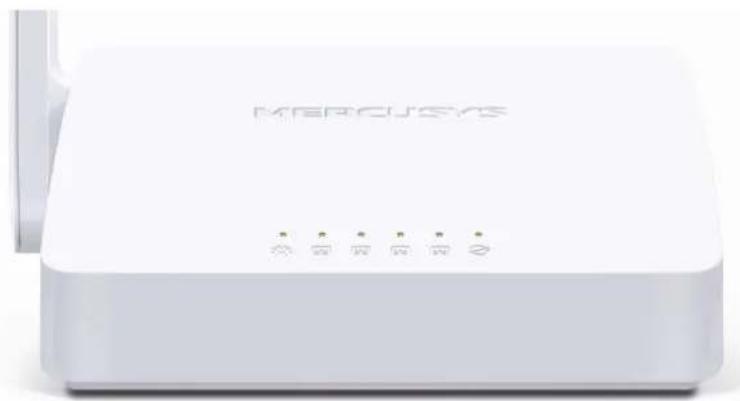
1.2.1 The Front Panel
natural_image
White wireless router device labeled 'MERCUSYS' with ports and indicator lights (no additional text or symbols visible)The router's LEDs are located on the front panel (View from left to right).
| Name | Status | Indication |
| (Power) | Off | Power is off. |
| On | Power is on. | |
| Flashing Slowly | Connection via WPS is in process. | |
| Flashing Quickly | Connection via WPS is failed | |
| (LAN) | Off | The corresponding port is not connected. |
| On | The corresponding port is connected. | |
| Flashing | The corresponding port is transmitting/receiving data. | |
| (WAN) | Off | The WAN port is not connected. |
| On | The WAN port is connected. | |
| Flashing | The WAN port is transmitting/receiving data. |
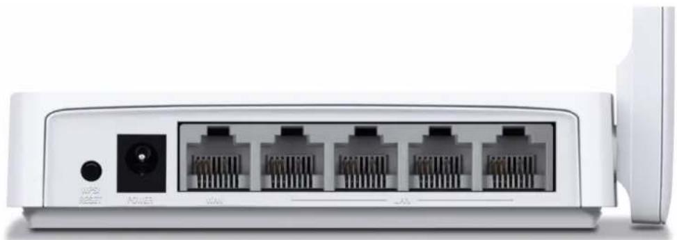
1.2.2 The Rear Panel
natural_image
Front view of a white networking device showing four Ethernet ports and a power outlet (no text or symbols visible)The following ports are located on the rear panel (View from left to right).
| Port Description | |
| WPS/RESET | The switch for the WPS function.Press for about one second to establish connection via WPS. For details, refer toWPS.Press and hold for more than 5 seconds to reset the router. |
| POWER | The power socket is where you will connect the power adapter. Please use the power adapter provided with this router. |
| WAN | This port is where you will connect the DSL/cable Modem, or Ethernet. |
| LAN | These ports connect the router to the local PC(s). |
| Wireless antenna | To receive and transmit the wireless data. |
Chapter 2. Connecting the Router
2.1 System Requirements
Broadband Internet Access Service (DSL/Cable/Ethernet)
One DSL/Cable Modem that has an RJ45 connector (which is not necessary if the router is connected directly to the Ethernet.)
PCs with a working Ethernet Adapter and an Ethernet cable with RJ45 connectors
▶ TCP/IP protocol on each PC
Web browser, such as Microsoft Internet Explorer, Mozilla Firefox or Apple Safari
2.2 Installation Environment Requirements
Place the router in a well-ventilated place far from any heater or heating vent
Avoid direct irradiation of any strong light (such as sunlight)
Keep at least 2 inches (5 cm) of clear space around the router
Operating Temperature: 0°C\~40°C (32°F\~104°F)
Operating Humidity: 10%\~90%RH, Non-condensing
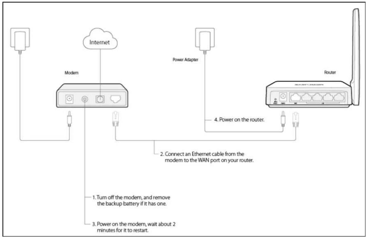
2.3 Connecting the Router
If your Internet connection is through an Ethernet cable from the wall instead of through a DSL/Cable/Satellite modem, connect the Ethernet cable directly to the router's Internet port, then follow steps 4 and 5 to complete the hardware connection.
- Turn off the modem and remove the backup battery if it has one.
- Connect the modem to the Internet port on your router with an Ethernet cable.
- Turn on the modem, and then wait about 2 minutes for it to restart.
- Turn on the router.
flowchart
graph TD
    A["Internet"] --> B["Modern"]
    B --> C["Power Adapter"]
    C --> D["Router"]
    B --> E["2. Connect an Ethernet cable from the modem to the WAN port on your router."]
    B --> F["1. Turn off the modem, and remove the backup battery if it has one."]
    B --> G["3. Power on the modem, wait about 2 minutes for it to restart."]
- Verify that the hardware connection is correct by checking these LEDs.

Power
On

WAN
On/Flashing
Chapter 3. Quick Installation Guide
This chapter will show you how to configure the basic functions of your router using Quick Setup Wizard within minutes.
NOTE:
Before configuring the router, you need to set up the TCP/IP Protocol in Obtain an IP address automatically mode on your PC. For detailed instructions, please refer to Appendix B: Configuring the PC.
- To access the web management page, open a web browser and enter http://mwlogin.net in the address field.

- A login window will appear. Create a login password when prompted, then click OK. For subsequent login, use the password you have set.
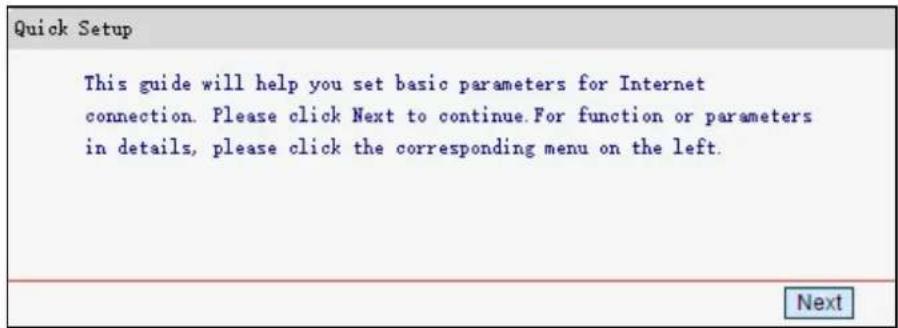
- After your successful login, you will see Quick Setup screen to shown as below. Click Next to continue.
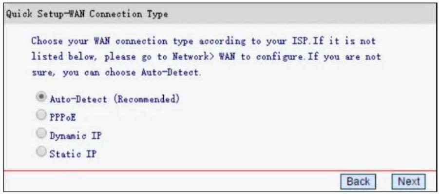
- Select Auto-Detect (Recommended), and the router will automatically detect your connection type. Then click Next.
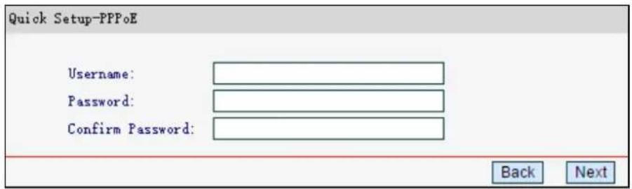
- Enter the Internet parameters provided by your ISP, then click Next. Here we use PPPoE as an example.
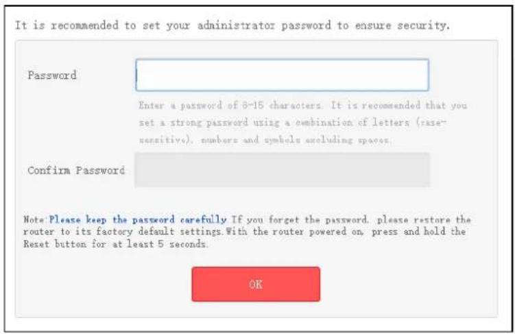
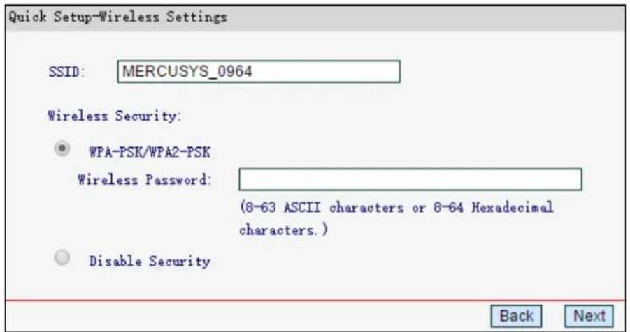
- Customize your SSID (wireless network name) and password, then click Next. It is strongly recommended to set a strong password to ensure security.
7. Click Finish to complete the Quick Setup.

Chapter 4. Configuring the Router
This chapter will show each web page's key functions and the configuration way.
After your successful login, you will see the main menus on the left of the web management page. On the right, there are the corresponding explanations and instructions.
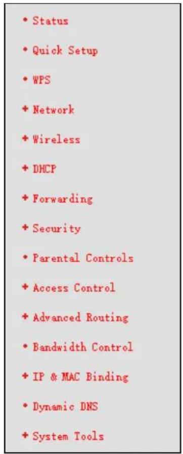
The detailed explanations for each web page's key function are listed below.
4.1 Status
The Status page provides the current status information about the router. All information is read-only.
| Version Info | ||
| Firmware Version: | ||
| Hardware Version: | ||
| LAN | ||
| MAC Address: | BC-5F-F6-10-09-64 | |
| IP Address: | 192.168.1.1 | |
| Subnet Mask: | 255.255.255.0 | |
| Wireless | ||
| Wireless Radio: | Enabled | |
| SSID: | MERCUSYS_0964 | |
| Channel: | Auto(Current channel 6) | |
| Mode: | 11bgn mixed | |
| Channel Width: | Auto | |
| MAC Address: | BC-5F-F6-10-09-64 | |
| WDS Status: | Disabled | |
| WAN | ||
| MAC Address: | BC-5F-F6-10-09-65 | |
| IP Address: | 0.0.0.0 | Dynamic IP |
| Subnet Mask: | 0.0.0.0 | |
| Default Gateway: | 0.0.0.0 | WAN port is disconnected. |
| DRS Server: | 0.0.0.0, 0.0.0.0 | |
| Traffic Statistics | ||
| Received | Sent | |
| Bytes: | 0 | 176 |
| Packets: | 0 | 4 |
| System Up Time: | 0 Day(s) 01:00:03 | Refresh |
4.2 WPS
This section guides you to add a new wireless device to an existing network quickly via WPS (Wi-Fi Protected Setup).
Choose WPS, and you will see the next screen.
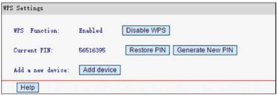
WPS Function – Displays the status of the WPS function. You can enable or disable the function here.
Current PIN – Displays the current value of the router's PIN. The default PIN of the router can be found in the label attached on the router.
Restore PIN - Restore the PIN of the router to its default.
Generate New PIN - Click to get a new random value for this device's PIN. You can ensure the network security by generating a new PIN.
- Add device - Click to add a new device to the existing network manually.
To add a new device:
If the wireless adapter supports WPS, you can establish a wireless connection between wireless adapter and router using either Push Button Configuration (PBC) method or PIN method.
NOTE:
To build a successful connection by WPS, you should also do the corresponding configuration the new device for WPS function meanwhile.
I. Use the Wi-Fi Protected Setup Button
Use this method if your client device has a Wi-Fi Protected Setup button.
Step 1: Press the WPS/RESET button on the back panel of the router for one second.
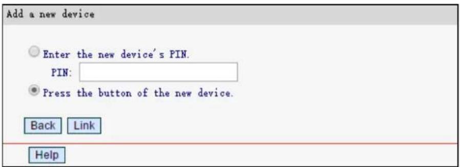
You can also keep the default WPS Status as Enabled and click Add Device, then choose Press the button of the new device and click Link.
Step 2: Press and hold the WPS button of the client device directly.
Step 3: The Power LED flashes during the Wi-Fi Protected Setup process.
Step 4: When the Power LED is on, the client device has successfully connected to the router.
Refer back to your client device or its documentation for further instructions.
II. Enter the client device's PIN on the router
Use this method if your client device has a WPS PIN number.
Step 1: Keep the WPS Function as Enabled and click Add Device, then the following screen will appear.
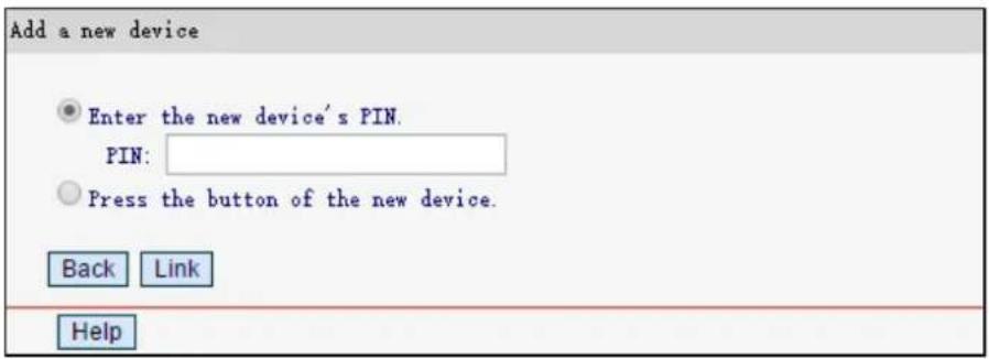
Step 2: Enter the PIN number of the client device, then click Link.
Step 3: Success! will appear on the screen, which means the client device has successfully connected to the router.
III. Enter the router's PIN on your client device
Use this method if your client device asks for the router's PIN number.
Step 1: On the client device, enter the PIN number listed on the router's Wi-Fi Protected Setup screen. (It is also labeled on the bottom of the router.)
Step 2: The Power LED flashes for two minutes during the Wi-Fi Protected Setup process.
Step 3: When the Power LED is on, the client device has successfully connected to the router. Refer back to your client device or its documentation for further instructions.
NOTE:
The WPS function cannot be configured if the Wireless Function of the router is disabled. Please make sure the Wireless Function is enabled before configuring the WPS.
4.3 Network
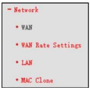
There are four submenus under the Network menu: WAN, WAN Rate Settings, LAN, and MAC Clone. Click any of them, and you can configure the corresponding function.
4.3.1 WAN
Go to Network → WAN, you can configure the IP parameters of the WAN.
- If your ISP provides the DHCP service, select Dynamic IP, and the router will automatically get IP parameters from your ISP.
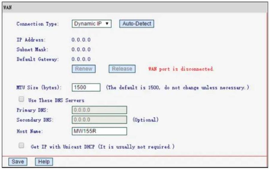
This page displays the WAN IP parameters assigned dynamically by your ISP, including IP address, subnet mask, default gateway, etc. Click Renew to renew the IP parameters from your ISP. Click Release to release the IP parameters.
MTU Size - The normal MTU (Maximum Transmission Unit) value for most Ethernet networks is 1500 Bytes. It is not recommended that you change the default MTU Size unless required by your ISP.
Use These DNS Servers - If your ISP gives you one or two DNS addresses, select Use These DNS Servers and enter the primary and secondary addresses into the correct fields. Otherwise, the DNS servers will be assigned dynamically from your ISP.
Get IP with Unicast DHCP - A few ISPs' DHCP servers do not support the broadcast applications. If you cannot get the IP Address normally, you can choose this option. (It is rarely required.)
Click Save to make your settings effective.
- If your ISP provides a static or fixed IP Address, Subnet Mask, Gateway and DNS setting, select Static IP.
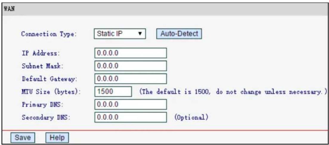
IP Address - Enter the IP address in dotted-decimal notation provided by your ISP.
Subnet Mask - Enter the subnet Mask in dotted-decimal notation provided by your ISP, usually is 255.255.255.0.
Default Gateway - (Optional) Enter the gateway IP address in dotted-decimal notation provided by your ISP.
MTU Size - The normal MTU (Maximum Transmission Unit) value for most Ethernet networks is 1500 Bytes. It is not recommended that you change the default MTU Size unless required by your ISP.
Primary/Secondary DNS - (Optional) Enter one or two DNS addresses in dotted-decimal notation provided by your ISP.
Click Save to save your settings.
- If your ISP provides a PPPoE connection, select PPPoE, then enter the following parameters.
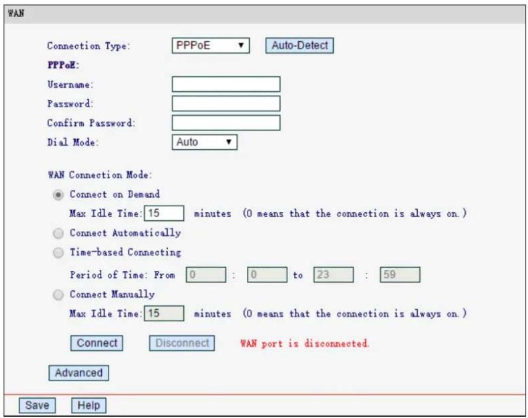
Username/Password - Enter the username and password provided by your ISP. These fields are case-sensitive.
Connect on Demand - In this mode, the Internet connection can be terminated automatically after a specified inactivity period (Max Idle Time) and be re-established when you attempt to access the Internet again. If you want your Internet connection keeps active all the time, please enter 0 in the Max Idle Time field. Otherwise, enter the number of minutes you want to have elapsed before your Internet access disconnects.
Connect Automatically - The connection can be re-established automatically when it is down.
Time-based Connecting - The connection will only be established in the period from the start time to the end time (in HH:MM format).
Connect Manually - You can click Connect/Disconnect to connect/disconnect immediately. This mode also supports the Max Idle Time function as Connect on Demand mode. The Internet connection can be disconnected automatically after a specified inactivity period and re-established when you attempt to access the Internet again.
Click Connect to connect immediately.
Click Disconnect to disconnect immediately.
NOTE:
Caution: Sometimes the connection cannot be terminated although you specify a time to Ma Idle Time, since some applications are visiting the Internet continually in the background.
If you want to do some advanced configurations, click Advanced, and you can see the page shown below.
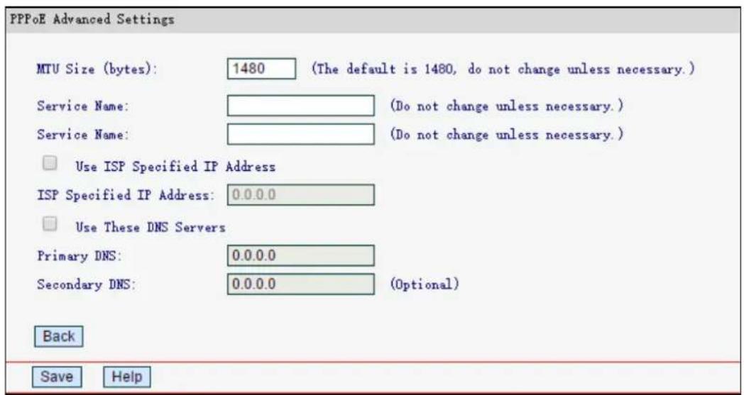
MTU Size - The default MTU size is 1480 bytes. It is NOT recommended that you change the default MTU Size unless required by your ISP.
Service Name - The service and server name, which should not be configured unless you are sure it is necessary for your ISP. In most cases, leaving these fields blank will work.
ISP Specified IP Address - If your ISP does not automatically assign IP addresses to the router during login, select Use IP address specified by ISP and enter the IP address provided by your ISP in dotted-decimal notation.
Primary/Secondary DNS - If your ISP does not automatically assign DNS addresses to the router during login, select Use the following DNS servers and enter the IP address in dotted-decimal notation of your ISP's primary DNS server. If a secondary DNS server address is available, enter it as well.
Click Save to make your settings effective.
4.3.2 WAN Rate Settings
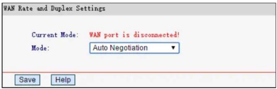
Current Mode - Displays the current WAN rate and duplex mode.
Mode - Select the rate and duplex mode for the WAN port from the drop-down list (100 Mbps Full Duplex, 100 Mbps Half Duplex, 10 Mbps Full Duplex or 10 Mbps Half Duplex).
4.3.3 LAN
Go to Network → LAN, you can configure the IP parameters of the LAN on the screen as below.
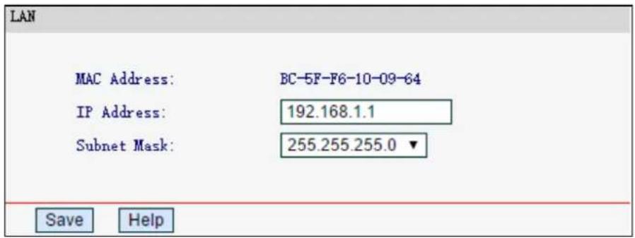
MAC Address - The physical address of the router, as seen from the LAN. The value can't be changed.
IP Address - Enter the IP address of your router in dotted-decimal notation (factory default: 192.168.1.1).
Subnet Mask - An address code that determines the size of the network. Normally use 255.255.255.0 as the subnet mask.
Click Save to make the settings effective. And the router will reboot automatically.
NOTE:
If you change the LAN IP address, you must use the new IP address to log in to the router.
4.3.4 MAC Clone
Go to Network → MAC Clone, you can configure the MAC address of the WAN on the screen below.
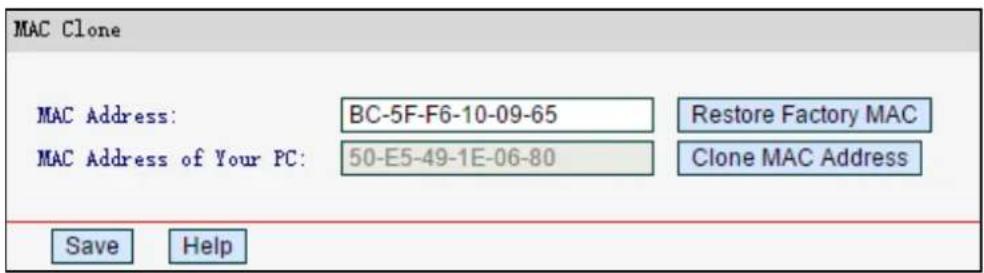
Some ISPs require that you register the MAC Address of your adapter. Changes are rarely needed here.
MAC Address - Displays the current MAC address of the WAN port. If your ISP requires you to register the MAC address, please enter the correct MAC address into this field in XX-XX-XX-XX-XX-XX format(X is any hexadecimal digit).
MAC Address of your PC - Displays the MAC address of the PC that is managing the router. If the MAC address is required, you can click Clone MAC Address and this MAC address will fill in the MAC Address field.
Click Save to make your settings effective.
NOTE:
Only the PC on your LAN can use the MAC Clone function
4.4 Wireless
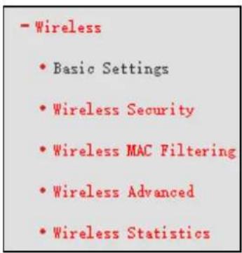
There are five submenus under the Wireless menu: Basic Settings, Wireless Security, Wireless MAC Filtering, Wireless Advanced and Wireless Statistics. Click any of them, and you will be able to configure the corresponding function.
4.4.1 Basic Settings
Go to Wireless→Wireless Setting, you can configure the basic settings for the wireless network on this page.
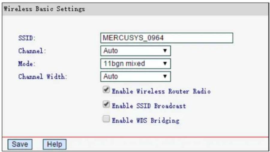
SSID - Wireless Network Name. The default SSID is set to be MERCUSYS_XXXX (XXXX indicates the last unique four numbers of each router's MAC address). This value is case-sensitive.
Channel - This field determines which operating frequency will be used. The default channel is set to Auto, so the AP will choose the best channel automatically. It is not necessary to change the wireless channel unless you notice interference problems with another nearby access point.
➢ Mode - Select the desired mode. The default setting is 11bgn mixed.
11b only - Select if you are using 802.11b wireless clients only.
11g only - Select if you are using 802.11g wireless clients only.
11n only - Select if you are using 802.11n wireless clients only.
11bg mixed - Select if you are using both 802.11b and 802.11g wireless clients.
11bgn mixed - Select if you are using a mix of 802.11b, 11g, and 11n wireless clients.
Select the desired wireless mode. It is strongly recommended that you set the mode to 802.11bgn mixed, and all of 802.11b, 802.11g, and 802.11n wireless stations can connect to the router.
Channel width - Select any channel width from the drop-down list. The default setting is Auto, which can adjust the channel width for your clients automatically.
NOTE:
If 11b only, 11g only, or 11bg mixed is selected, the Channel Width field will turn grey and the value will become 20M, which is unable to be changed.
Enable Wireless Router Radio - The wireless radio of this router can be enabled or disabled to allow wireless stations access.
Enable SSID Broadcast - When wireless clients survey the local area for wireless networks to associate with, they will detect the SSID broadcast by the router. If you select the Enable SSID Broadcast, the wireless router will broadcast its name (SSID) on the air.
Enable WDS Bridging - Select to enable WDS. With this function, the router can bridge two or more WLANs. If this checkbox is selected, you will have to set the following parameters as shown below. Make sure the following settings are correct
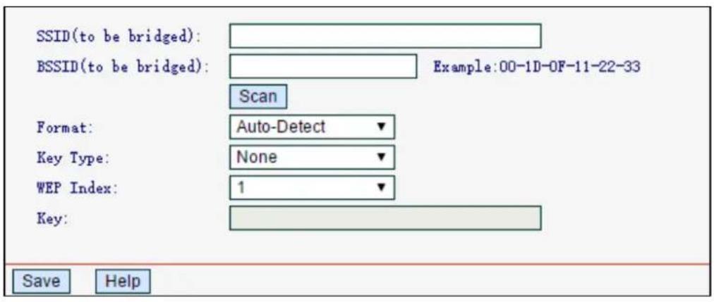
SSID (to be bridged) - The SSID of the AP your router is going to connect to as a client. You can also use the scan function to select the SSID to join.
BSSID (to be bridged) - The BSSID of the AP your router is going to connect to as a client. You can also use the scan function to select the BSSID to join.
➢ Scan - Click to search the AP which runs in the current channel.
Format - Select Auto-Detect, Triple Address or Quadruple Address. It is recommended you keep the default Auto-Detect.
Key type - This option should be chosen according to the AP's security configuration. It is recommended that the security type is the same as your AP's security type.
WEP Index - This option should be chosen if the key type is WEP. It indicates the index of the WEP key.
Key - If the AP your router is going to connect needs password, you need to enter the password in this filed.
4.4.2 Wireless Security
Go to Wireless Wireless Security, you can configure the security settings of your wireless network.
There are five wireless security modes supported by the router: WEP (Wired Equivalent Privacy), WPA (Wi-Fi Protected Access), WPA2 (Wi-Fi Protected Access 2), WPA-PSK (Pre-Shared Key), WPA2-PSK (Pre-Shared Key).
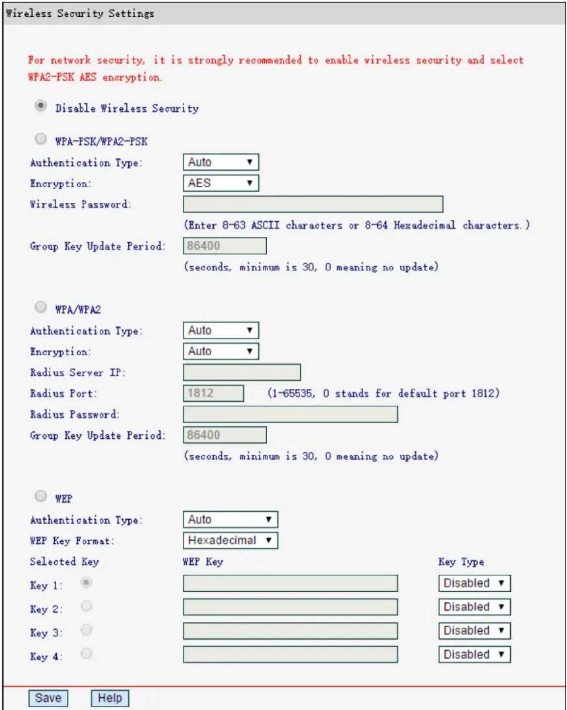
Disable Wireless Security - If you do not want to use wireless security, select this option, but it's strongly recommended to choose one of the following modes to enable security.
WPA-PSK/WPA2-PSK - The WPA/WPA2 authentication type based on pre-shared passphrase.
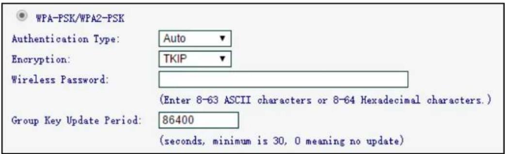
- Encryption - you can choose the version of the WPA-PSK security from the drop-down list. The default setting is Auto, which can select WPA-PSK or WPA2-PSK automatically based on the wireless station's capability and request.
- Encryption - When WPA-PSK or WPA is set as the Authentication Type, you can select either Auto, TKIP or AES as Encryption.
- Wireless Password - You can enter 8-63 ASCII characters or 8-64 Hexadecimal characters.
- Group Key Update Period - Specify the group key update interval in seconds. The value should be 30 or above. Enter 0 to disable the update.
Click Save to make your settings effective.
WPA /WPA2 - The WPA/WPA2 authentication type based on based on Radius Server.
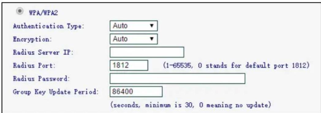
- Authentication Type - you can choose the version of the WPA security on the drop-down list. The default setting is Automatic, which can select WPA (Wi-Fi Protected Access) or WPA2 (WPA version 2) automatically based on the wireless station's capability and request.
- Encryption - You can select either Automatic, or TKIP or AES.
- Radius Server IP - Enter the IP address of the Radius Server.
- Radius Port - Enter the port that radius service used.
- Radius Password - Enter the password for the Radius Server.
- Group Key Update Period - Specify the group key update interval in seconds. The value should be 30 or above. Enter 0 to disable the update.
WEP - It is based on the IEEE 802.11 standard. If you select this check box, you will find a notice in red as show below.
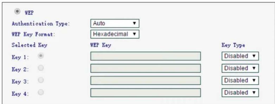
- Authentication Type - You can choose the type for the WEP security on the pull-down list. The default setting is Auto, which can select Open System or Shared Key authentication type automatically based on the wireless station's capability and request.
- WEP Key Format - Hexadecimal and ASCII formats are provided. Hexadecimal format stands for any combination of hexadecimal digits (0-9, a-f, A-F) in the specified length. ASCII format stands for any combination of keyboard characters in the specified length.
- Selected Key - Select which of the four keys will be used and enter the matching WEP key that you create.
- Key Type - You can select the WEP key length (64-bit, or 128-bit) for encryption. Disabled means this WEP key entry is invalid.
64-bit - You can enter 10 hexadecimal digits (any combination of 0-9, a-f, A-F, zero key is not promoted) or 5 ASCII characters.
128-bit - You can enter 26 hexadecimal digits (any combination of 0-9, a-f, A-F, zero key is not promoted) or 13 ASCII characters.
4.4.3 Wireless MAC Filtering
Go to Wire less → Wireless MAC Filtering, you can control the wireless access by configuring the Wireless MAC Address Filtering function.
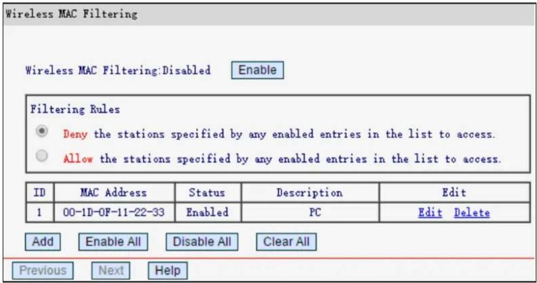
To filter wireless users by MAC Address, click Enable. The default setting is Disabled.
MAC Address - The wireless station's MAC address that you want to filter.
➢ Status - The status of this entry either Enabled or Disabled.
➢ Description - A simple description of the wireless station.
Click Enable All/ Disable All to make all entries enabled/disabled.
Click Clear All to delete all entries
Click Next to go to the next page or click Previous to return to the previous page.
To add or modify a MAC Address Filtering entry, follow these instructions:
- Click Add, The following page will appear.
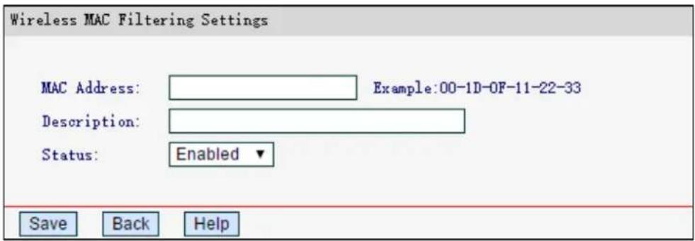
- Enter the appropriate MAC Address into the MAC Address field. The format of the MAC Address is XX-XX-XX-XX-XX-XX (X is any hexadecimal digit).
- Enter a simple description of the wireless station in the Description field.
- Status - Select Enabled or Disabled for this entry on the Status pull-down list.
- Click Save .
To modify or delete an existing entry:
- Click Edit in the entry you want to modify. If you want to delete the entry, click the Delete.
- Modify the information.
- Click Save.
4.4.4 Wireless Advanced
Go to Wireless-Wireless Advanced, you can configure the advanced settings of your wireless network.
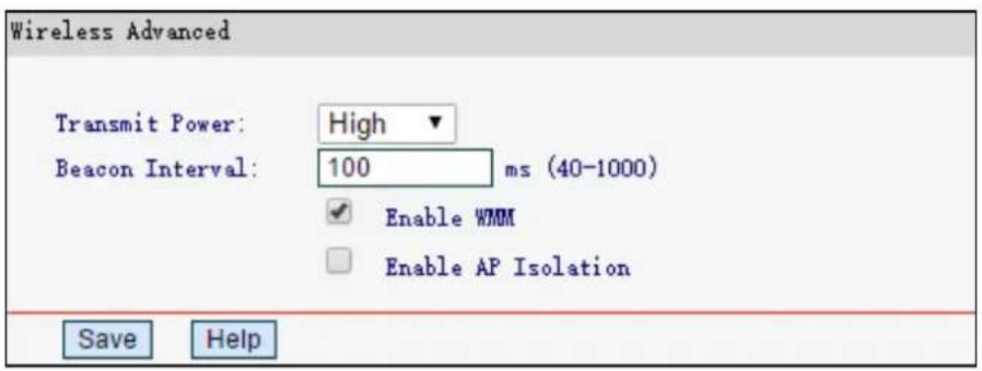
➢ Transmit Power - You can specify the transmit power of router. Select High, Middle or Low according to your needs. High is the default setting and is recommended.
Beacon Interval - Enter a value between 40-1000 milliseconds for Beacon Interval here. The beacons are the packets sent by the router to synchronize a wireless network. Beacon Interval value determines the time interval of the beacons. The default value is 100.
Enable WMM - WMM function can guarantee the packets with high-priority messages being transmitted preferentially. It is strongly recommended enabled.
Enabled AP Isolation - This function can isolate wireless stations on your network from each other. Wireless devices will be able to communicate with the router but not with each other. To use this function, check this box. AP Isolation is disabled by default.
NOTE:
If you are not familiar with the setting items in this page, it's strongly recommended to keep the provided default values; otherwise it may result in lower wireless network performance.
4.4.5 Wireless Statistics
Go to Wire less→Wireless Statistics, you can see the MAC Address, Current Status, Received Packets and Sent Packets for each connected wireless station.
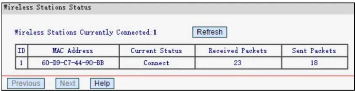
MAC Address - The connected wireless station's MAC address.
Current Status - The connected wireless station's running status.
Received Packets - Packets received by the station.
Sent Packets - Packets sent by the station.
You cannot change any of the values on this page. To update this page and to show the current connected wireless stations, click Refresh.
If the numbers of connected wireless stations go beyond one page, click Next to go to the next page and click Previous to return the previous page.
NOTE:
This page will be refreshed automatically every 10 seconds.
4.5 DHCP
There are three submenus under the DHCP menu: DHCP Settings, DHCP Clients List and Address Reservation. Click any of them, and you will be able to configure the corresponding function.
4.5.1 DHCP Settings
Go to DHCP→DHCP Settings, you can configure the DHCP Server on the page. The router is set up by default as a DHCP (Dynamic Host Configuration Protocol) server, which provides the TCP/IP configuration for all the PC(s) that are connected to the router on the LAN.
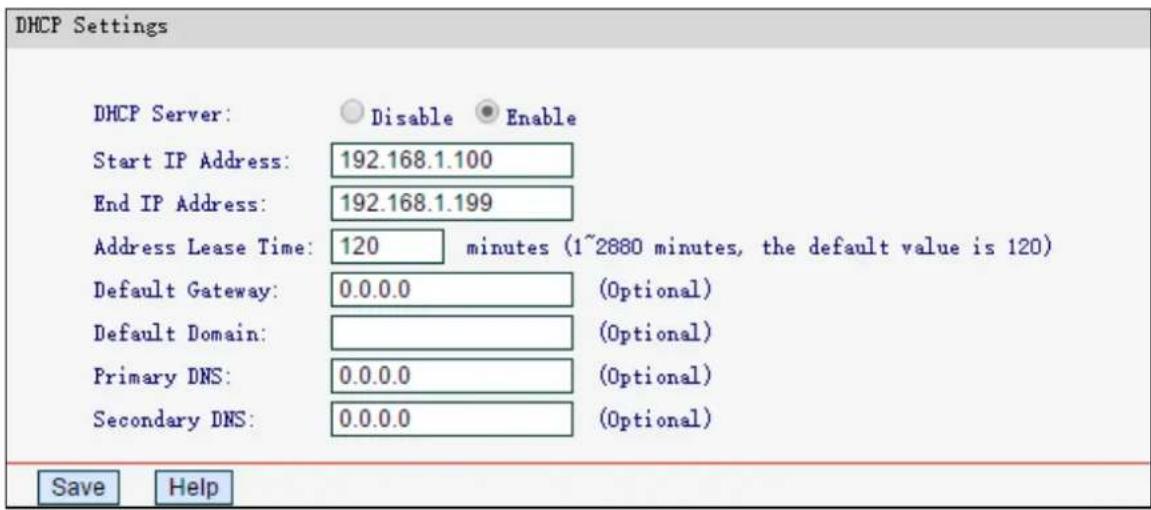
DHCP Server - Enable or Disable the DHCP server. If you disable the Server, you must have another DHCP server within your network or else you must configure the computer manually.
Start IP Address - Specify an IP address for the DHCP server to start with when assigning IP addresses. 192.168.1.100 is the default start address.
End IP Address - Specify an IP address for the DHCP Server to end with when assigning IP addresses. 192.168.1.199 is the default end address.
Address Lease Time - The Address Lease Time is the amount of time a network user will be allowed connection to the router with their current dynamic IP Address. Enter the amount of time in minutes and the user will be "leased" this dynamic IP Address. After the time is up, the user will be automatically assigned a new dynamic IP address. The range of the time is 1 \~ 2880 minutes. The default value is 120 minutes.
Default Gateway - (Optional.) It is suggested to enter the IP address of the LAN port of the router, default value is 192.168.1.1
Default Domain - (Optional.) Enter the domain name of your network.
Primary DNS - (Optional.) Enter the DNS IP address provided by your ISP.
Secondary DNS - (Optional.) Enter the IP address of another DNS server if your ISP provides two DNS servers.
NOTE:
To use the DHCP server function of the router, you must configure all computers on the LAN as Obtain an IP Address automatically mode.
4.5.2 DHCP Client List
Go to DHCP→DHCP Client List, you can view the information about the clients attached to the router in the next screen.
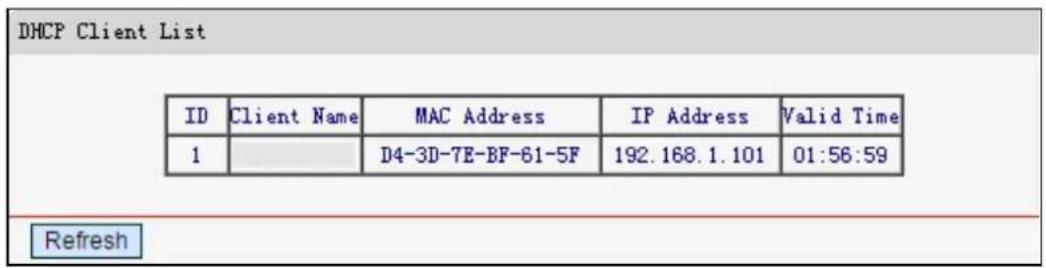
ID - The index of the DHCP Client.
Client Name - The name of the DHCP client.
MAC Address - The MAC address of the DHCP client.
IP Address - The IP address that the router has allocated to the DHCP client.
Valid Time - The time of the DHCP client leased. After the dynamic IP address has expired, a new dynamic IP address will be automatically assigned to the user.
You cannot change any of the values on this page. Click Refresh to update this page and to show the current attached devices.
4.5.3 Address Reservation
Go to DHCP→Address Reservation, you can view and add a reserved addresses for clients via the next screen. When you specify a reserved IP address for a PC on the LAN, the PC will always receive the same IP address each time it accesses the DHCP server.

MAC Address - The MAC address of the PC for which you want to reserve IP address.
IP Address - The IP address of the router reserved.
Status - The status of this entry, either Enabled or Disabled.
To Reserve IP addresses:
- Click Add.
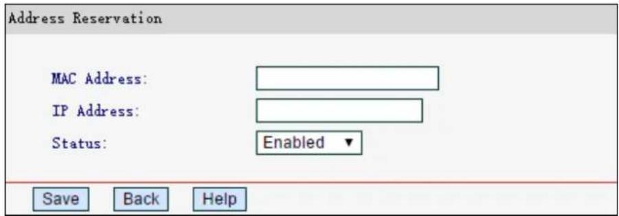
- Enter the MAC address (in XX-XX-XX-XX-XX-XX format.) and IP address in dotted-decimal notation of the computer you wish to add.
- Click Save.
To modify or delete an existing entry:
- Click Edit in the entry you want to modify. If you want to delete the entry, click Delete.
- Modify the information.
- Click Save.
Click Enable All/Disable All to make all entries enabled/disabled.
Click Delete All to delete all entries.
Click Next to go to the next page and click Previous to return the previous page.
4.6 Forwarding
There are three submenus under the Forwarding menu: Virtual Servers, DMZ and UPnP. Click any of them, and you will be able to configure the corresponding function.
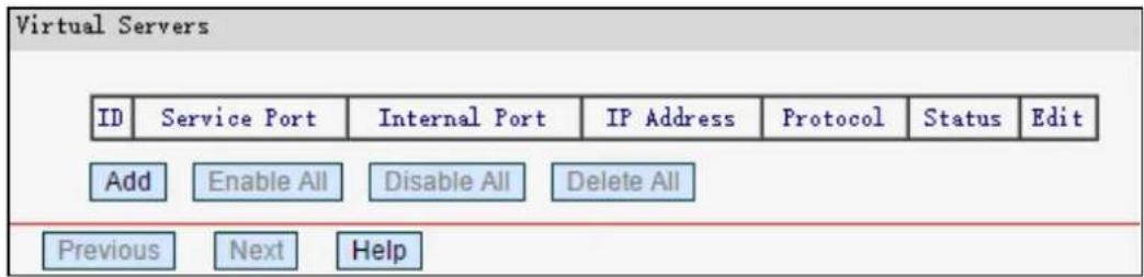
4.6.1 Virtual Servers
Go to Forwarding→Virtual Servers, you can view and add virtual servers. Virtual servers can be used for setting up public services on your LAN, such as DNS, Email and FTP. A virtual server is defined as a service port, and all requests from the Internet to this service port will be redirected to the computer specified by the server IP. Any PC that was used for a virtual server must have a static or reserved IP Address because its IP Address may be changed when using the DHCP function.
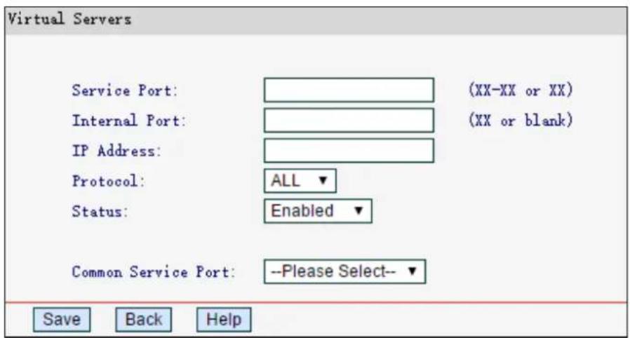
Service Port - The numbers of external ports. You can type a service port or a range of service ports (in XX – YY format, XX is the start port number, YY is the end port number).
Internal Port - The internal service port number of the PC running the service application. You can leave it blank if the Internal Port is the same as the Service Port, or enter a specific port number when Service Port is a single one.
IP Address - The IP address of the PC providing the service application.
Protocol - The protocol used for this application, either TCP, UDP, or AII (all protocols supported by the router).
Status - The status of this entry either Enabled or Disabled.
To set up a virtual server entry:
- Click Add.
- Enter the service port or select the service you want to use from the Common Service Port list.
- Enter the IP address of the computer in the IP Address field.
- Select the protocol used for this application, either All, TCP or UDP.
- Select Enable to enable the virtual server.
- Click Save.
To modify or delete an existing entry:
- Click Edit in the entry you want to modify. If you want to delete the entry, click Delete.
- Modify the information.
- Click Save.
Click Enable All/Disabled All to make all entries enabled/disabled.
Click Delete All to delete all entries.
Click Next to go to the next page and click Previous to return the previous page.
NOTE:
The port number of virtual servers cannot be the same as the remote management podn Security→Remote Management page.
4.6.2 DMZ
Go to Forwarding DMZ, you can view and configure DMZ host in the screen. The DMZ host feature allows one local host to be exposed to the Internet for a special-purpose service such as Internet gaming or videoconferencing. DMZ host forwards all the ports at the same time. Any PC whose port is being forwarded must have its DHCP client function disabled and should have a new static IP Address assigned to it because its IP Address may be changed when using the DHCP function.
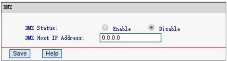
To assign a computer or server to be a DMZ server:
- Select Enable.
- Enter the local host IP Address in the DMZ Host IP Address field.
- Click Save.
4.6.3 UPnP
Go to Forwarding→UPnP, you can view the information about UPnP (Universal Plug and Play) in the screen. The UPnP feature allows the devices, such as Internet computers, to access the local host resources or devices as needed. UPnP devices can be automatically discovered by the UPnP service application on the LAN.
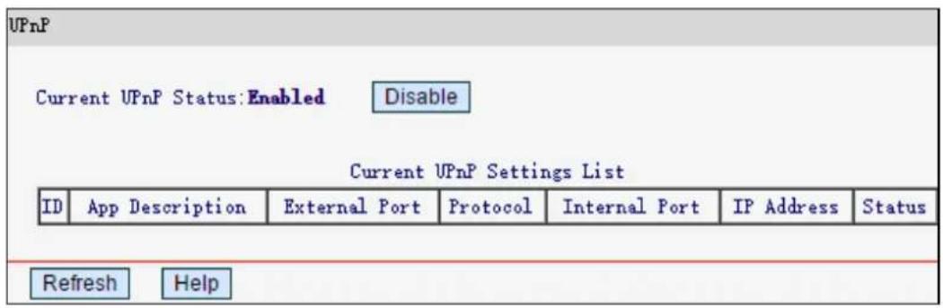
Current UPnP Status - UPnP can be enabled or disabled by clicking Enable or Disable. The feature is enabled by default.
Current UPnP Settings List - Displays the current UPnP information.
- App Description -The description provided by the application in the UPnP request
- External Port – The external port which the router opened for the application.
• Protocol - Displays the type of protocol opened. - Internal Port – The internal port which the router opened for local host.
• IP Address - The IP address of the local host which initiates the UPnP request.
- Status - Either Enabled or Disabled. Enabled means that the port is still active; otherwise, the port is inactive.
Click Refresh to update the Current UPnP Settings List.
4.7 Security
There are two submenus under the Security menu: Local Management and Remote Management. Click any of them, and you will be able to configure the corresponding function.
4.7.1 Local Management
Go to Security→Local Management, you can configure the management rule. The management feature allows you to deny computers in LAN from accessing the router.
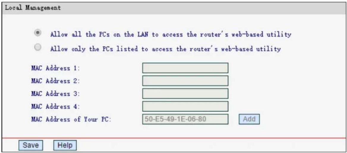
By default, Allow all the PCs on the LAN to access the router's web-based utility is selected. If you want to allow PCs with specific MAC addresses to access the router, select Allow only the PCs listed to access the router's web-based utility, and then enter each MAC Address in a separate field (in XX-XX-XX-XX-XX-XX format). Then only the PCs with MAC address listed can access the router to perform administrator tasks while other devices will be blocked.
Click Add to place your PC's MAC address in the list above.
Click Save to save your settings.
4.7.2 Remote Management
Go to Security→Remote Management, you can configure the remote management function. This feature allows you to manage your router from a remote location via the Internet.
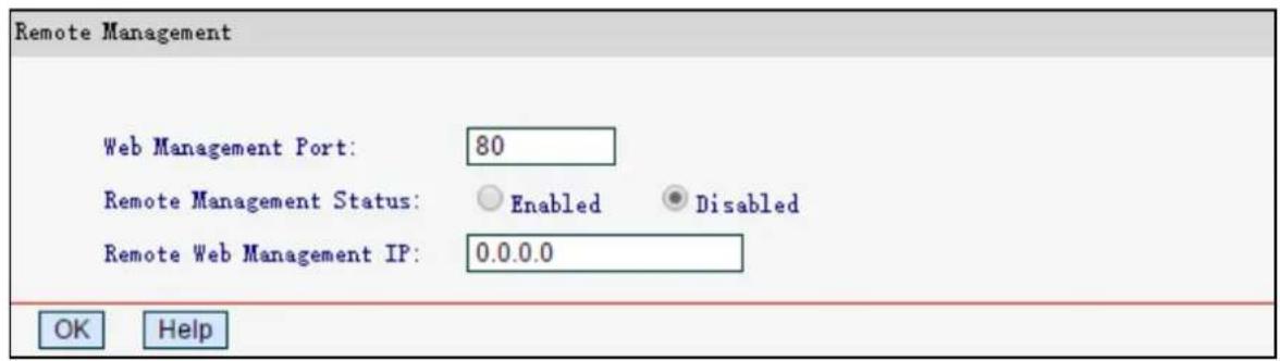
Web Management Port - Web browser access normally uses the standard HTTP service port 80. This router's default remote management web port number is 80. For better security, you can change the port to a custom port.
Remote Management IP Address - The current address you will use when accessing your router from the Internet. This function is disabled when the IP address is set to the default
value of 0.0.0.0. To enable this function change 0.0.0.0 to a valid IP address. If set to 255.255.255.255, then all the hosts can access the router from internet.
NOTE:
1) To access the router, you should type your router's WAN IP address into your browser address filed, followed by a colon and the custom port number. For example, if your router's WAN address is 202.96.12.8, and the port number used is 8080, please enter http://202.96.12.8:8080 in your browser. After successfully entering the password, you will be able to access the router's web management page.
2) Be sure to set a secure password for the router.
4.8 Parental Controls
Choose Parental Controls, and you can configure the parental control in the screen as shown below. The function can be used to control the internet activities of the child, limit the child to access certain websites and restrict the time of surfing.
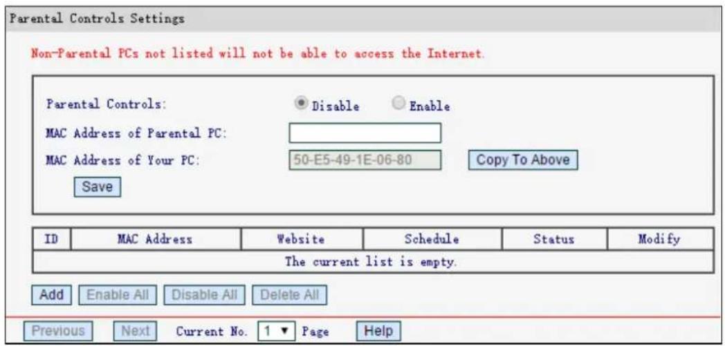
Parental Controls - Select Enable if you want this function to take effect, otherwise select Disable.
MAC Address of Parental PC - Enter the MAC address of the controlling PC, or you can make use of the Copy To Above button below.
MAC Address of Your PC - Displays the MAC address of the PC that is managing this router. If the MAC address of your adapter is registered, you can click Copy To Above to fill this address to the MAC Address of Parental PC field above.
MAC Address - Displays the MAC addresses of the PCs under control.
Website - Description of the allowed website for the PC under control.
Schedule - The time period allowed for the PC controlled to access the Internet.
Modify - Here you can edit or delete an existing entry.
Click Enable All/Disable All to enable/disable all the rules in the list.
Click Delete All to delete all the entries in the table.
Click Next to go to the next page, or click Previous return to the previous page.
To add a new entry, please follow the steps below.
1. Click Ad d.
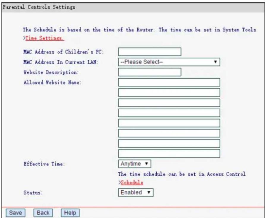
- Enter the MAC address of the PC in the MAC Address of Children's PC field. Or you can choose the MAC address from the MAC Address In Current LAN drop-down list.
- Give a description for the website allowed to be accessed in the Website Description field.
- Enter the allowed domain name of the website, either the full name or the keywords in the Allowed Website Name field. Any domain name with keywords in it will be allowed.
- Select from the Effective Time drop-down list the schedule you want the entry to take effect. If there are not suitable schedules for you, click the Schedule in red below to go to the schedule settings page and create the schedule you need.
- In the Status field, select Enabled or Disabled to enable or disable the entry.
- Click Save.
4.9 Access Control
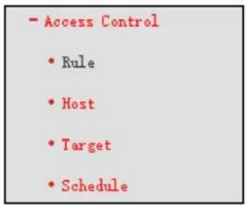
There are four submenus under the Access Control menu as shown below. Rule, Host, Target and Schedule. Click any of them, and you will be able to configure the corresponding function.
4.9.1 Rule
Go to Access Control→Rule, you can view and set access control rules.
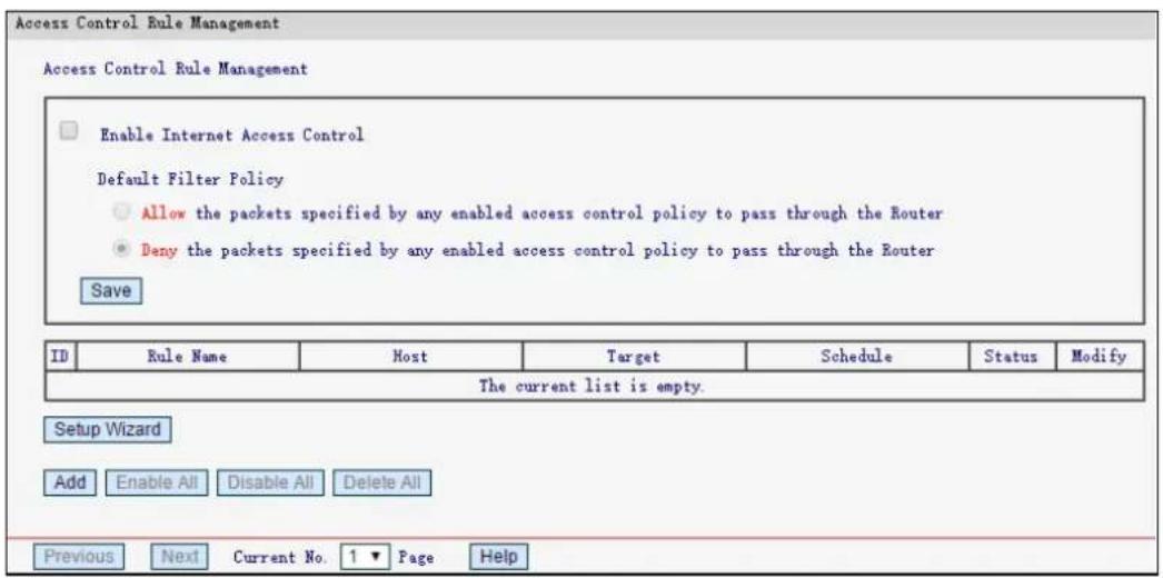
Enable Internet Access Control - Select to enable the Internet Access Control function, so the Default Filter Policy can take effect.
Rule Name - Here displays the name of the rule and this name is unique.
Host - Displays the host selected in the corresponding rule.
Target - Displays the target selected in the corresponding rule.
➢ Schedule - Displays the schedule selected in the corresponding rule.
Status - Displays the status of the rule. Enabled means the rule will take effect, Disabled means the rule will not take effect.
Modify - Here you can edit or delete an existing rule.
Click Enable All to enable all the rules in the list.
Click Disable All to disable all the rules in the list.
Click Delete All to delete all the entries in the table.
Click Next to go to the next page, or click Previous to return to the previous page.
To add a new rule, please follow the steps below.
1. Click Ad d.
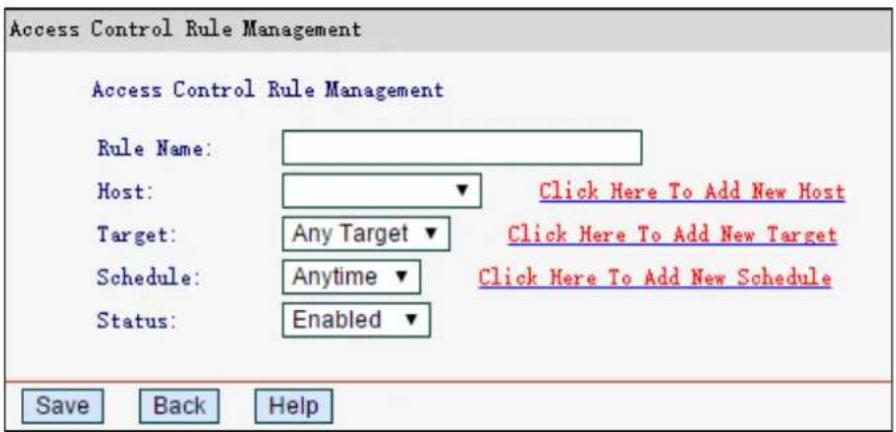
- Give a name for the rule in the Rule Name field.
- Select a host from the Host drop-down list or select Click Here To Add New Host to create one.
- Select a target from the Target drop-sown list or select Click Here To Add New Target to create one.
- Select a schedule from the Schedule drop-down list or select Click Here To Add New Schedule to create one.
- In the Status field, select Enabled or Disabled to enable or disable your entry.
- Click Save.
4.9.2 Host
Go to Access Control→Host, you can view and set a host list. The host list is necessary for the access control rule.

Host Name - Displays the description of the host and this description is unique.
Information - Displays the information about the host. It can be IP or MAC.
Modify - To edit or delete an existing entry.
To add a new entry, follow the steps below.
1. Click Add.
- In the Mode field, select IP Address or MAC Address.
- If you select IP Address:
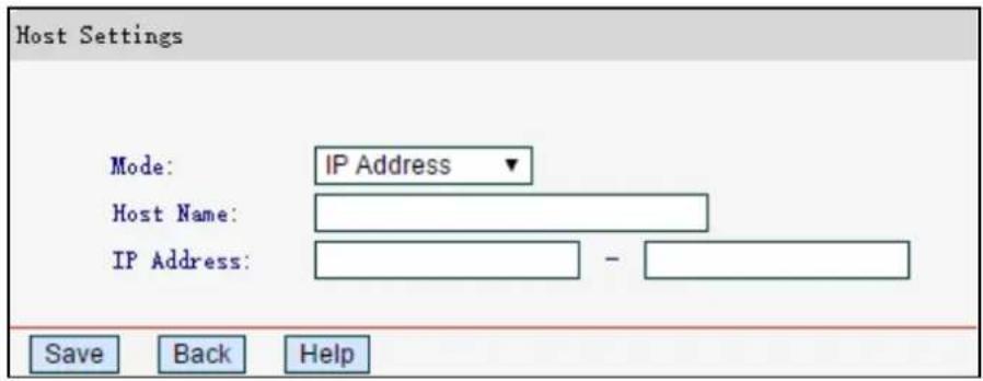
1) In Host Name field, create a unique description for the host (e.g. Host_1).
2) In IP Address field, enter the IP address.
- If you select MAC Address:
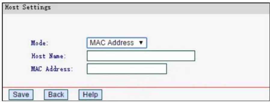
1) In Host Name field, create a unique description for the host (e.g. Host_1).
2) In MAC Address field, enter the MAC address.
3. Click Save.
Click Delete All to delete all the entries in the table.
Click Next to go to the next page, or click Previous to return to the previous page.
4.9.3 Target
Go to Access Control→Target, you can view and set a Target list. The target list is necessary for the Access Control Rule.
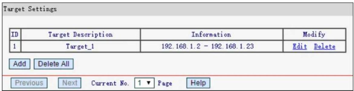
Target Description - Displays the description about the target and this description is unique.
Information - The target can be IP address, port or domain name.
Modify - To edit or delete an existing entry.
To add a new entry, follow the steps below.
- Click Ad d.
- In Mode field, select IP Address or Domain Name.
- If you select IP Address:
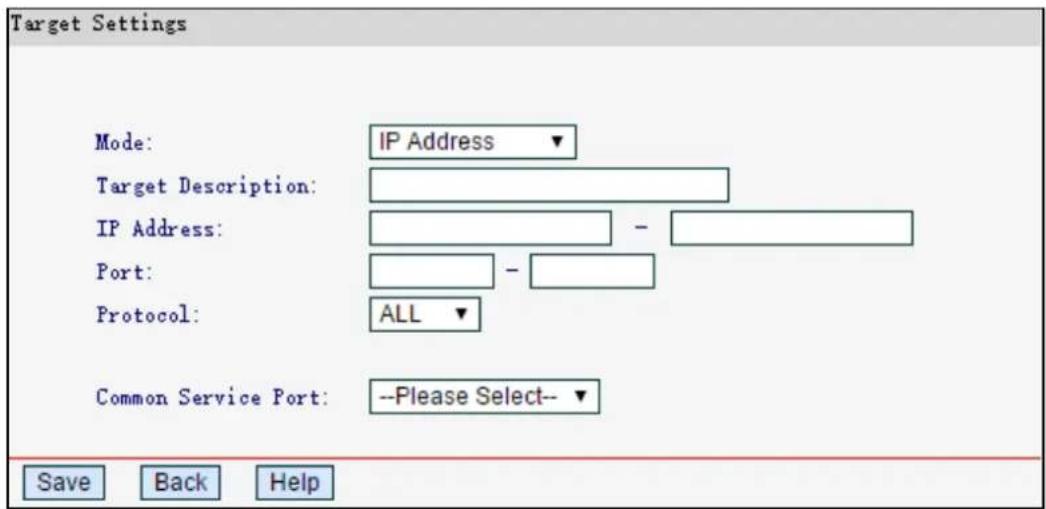
1) In Target Description field, create a unique description for the target (e.g. Target_1).
2) In IP Address field, enter the IP address of the target.
3) Select a common service from Common Service Port drop-down list, so that the Target Port will be automatically filled. If the Common Service Port drop-down list doesn't have the service you want, specify the Target Port manually.
4) In Protocol field, select ALL, TCP, UDP, or ICMP.
- If you select Domain Name:
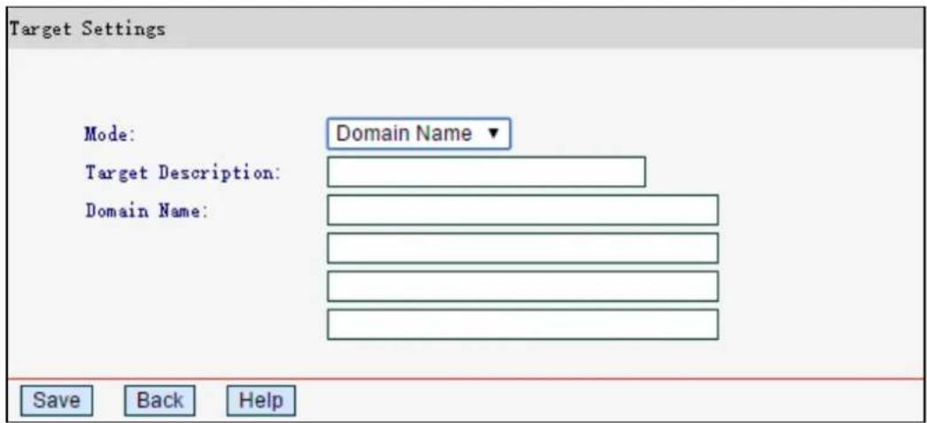
1) In Target Description field, create a unique description for the target (e.g. Target_1).
2) In Domain Name field, enter the domain name, either the full name or the keywords in the blank. Any domain name with keywords in it will be blocked or allowed. You can enter 4 domain names.
3. Click Save.
Click Delete All to delete all the entries in the table.
Click Next to go to the next page, or click Previous to return to the previous page.
4.9.4 Schedule
Go to Access Control → Schedule, you can view and set a schedule list. The schedule list is necessary for the Access Control Rule.
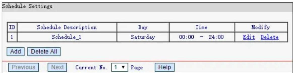
Schedule Description - Displays the description of the schedule and it is unique.
Day - Displays the day(s) in a week.
Time - Displays the time period in a day.
Modify - Here you can edit or delete an existing schedule.
Click Delete All to delete all the entries in the table.
Click Next to go to the next page, or click Previous to return to the previous page.
To add a new schedule, the steps below.
- Click Add.
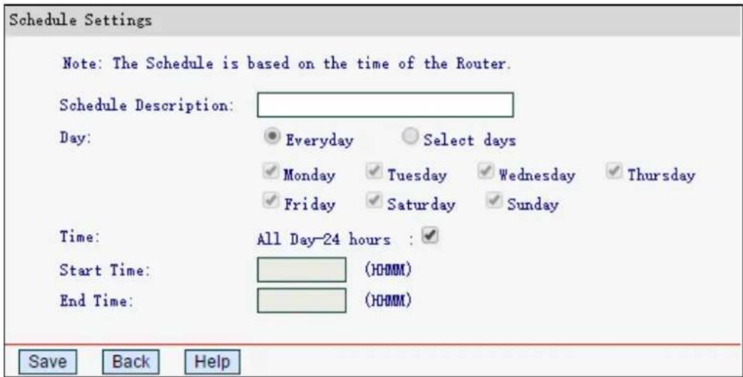
- In Schedule Description field, create a unique description for the schedule (e.g. Schedule_1).
- In Day field, select the day or days you need.
- In Time field, you can select all day-24 hours or you may enter the Start Time and End Time in the corresponding field.
- Click Save to complete the settings.
4.10 Advanced Routing
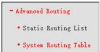
There are two submenus under the Advanced Routing menu: Static Routing List and System Routing Table. Click any of them, and you will be able to configure the corresponding function.
4.10.1 Static Routing List
Go to Advanced Routing→Static Routing List, and then you can configure the static route. A static route is a pre-determined path that network information must travel to reach a specific host or network.
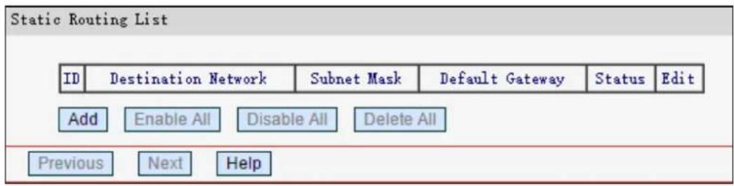
Destination Network - The address of the network or host that you want to assign to a static route.
Subnet Mask - The subnet mask determines which portion of an IP address is the network portion, and which portion is the host portion.
Default Gateway - This is the IP Address of the gateway device that allows for contact between the router and the network or host.
Click Enable All to enable all the entries.
Click Disable All to disable all the entries.
Click Delete All to delete all the entries.
Click Next to view the information in the next screen, or click Previous to view the information in the previous screen,
To add static routing entries:
1. Click Add.
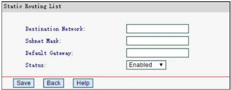
- Enter the destination network, subnet mask and default gateway in the corresponding field.
- Select Enabled or Disabled for this entry on the Status drop-down list.
- Click Save to make the entry take effect.
4.10.2 System Routing Table
Go to Advanced Routing→System Routing Table, and then you can view the system routing table. System routing table views all of the valid route entries in use. The Destination IP address, Subnet Mask, Gateway, and Interface will be displayed for each entry.
| ID | Destination Network | Subnet Mask | Default Gateway | Interface |
| 1 | 192.168.1.0 | 255.255.255.0 | 192.168.1.1 | LAN&WLAN |
| Refresh Help | ||||
Destination Network - The address of the network or host to which the static route is assigned.
Subnet Mask - The subnet mask determines which portion of an IP address is the network portion, and which portion is the host portion.
Default Gateway - This is the IP address of the gateway device that allows for contact between the router and the network or host.
Interface - This interface tells you either the Destination IP Address is on the LAN&WLAN (internal wired and wireless networks), or on the WAN (Internet).
4.11 Bandwidth Control
Choose Bandwidth Control, you can configure the upstream bandwidth and downstream bandwidth.
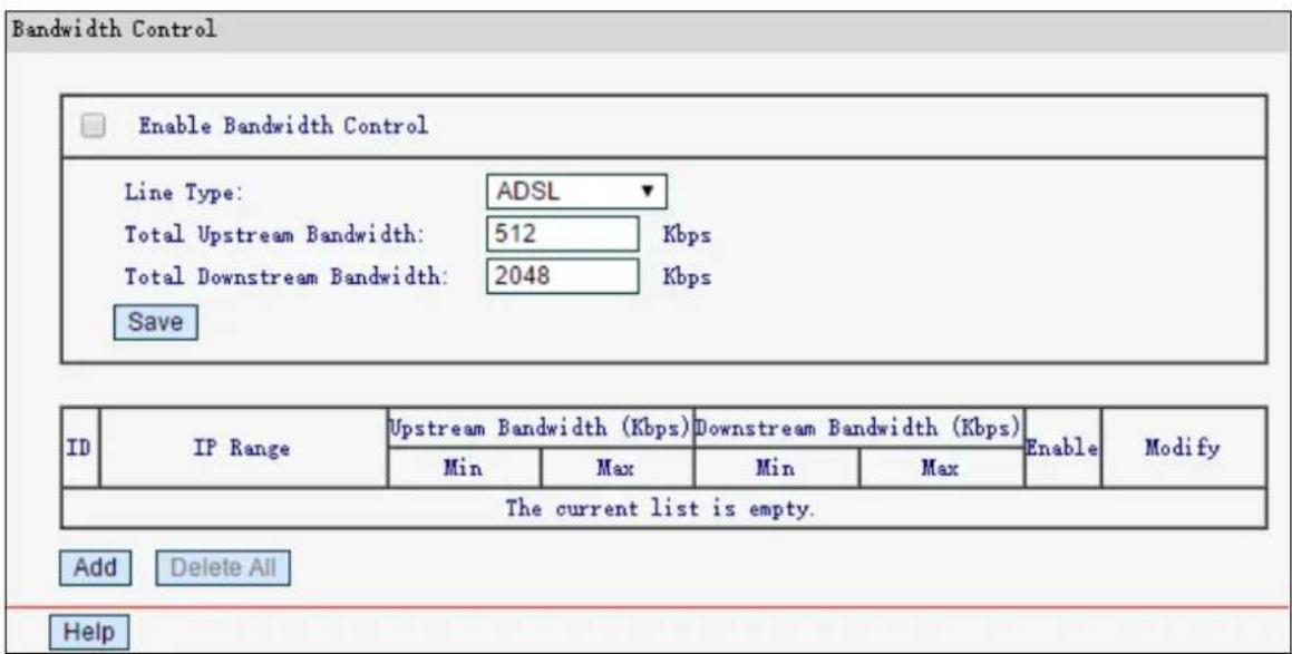
➢ Enable Bandwidth Control - Select this box so that the bandwidth control settings can take effect.
Line Type - Select the right type for you network connection. If you don't know how to choose, please ask your ISP for the information.
Total Upstream Bandwidth - The upload speed through the WAN port.
Total Downstream Bandwidth - The download speed through the WAN port.
IP Range - The information about the rules such as address range.
Upstream Bandwidth - Displays the min and max upload bandwidth through the WAN port.
➢ Downstream Bandwidth - Displays the min and max download bandwidth through the WAN port.
➢ Enable - Displays the status of the rule.
Modify- Here you can edit or delete the rule.
To add/modify a bandwidth control rule, follow the steps below.
Step 1: Click Add.
Step 2: Enter the information like the screen shown below.
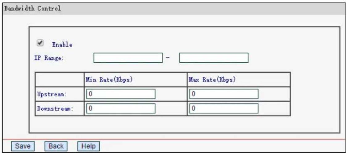
Step 3: Click Save.
4.12 IP & MAC Binding
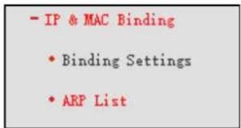
There are two submenus under the IP &MAC Binding menu: Binding Settings and ARP List. Click any of them, and you will be able to scan or configure the corresponding function.
4.12.1 Binding Settings
Go to IP & MAC Binding → Binding Settings, you can view and set the IP & MAC Binding table.
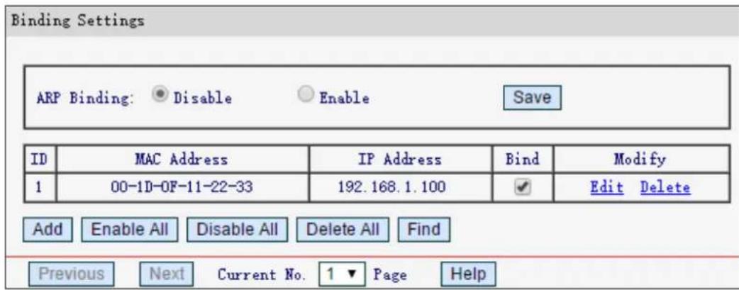
MAC Address - The MAC address of the controlled computer in the LAN.
IP Address - The assigned IP address of the controlled computer in the LAN.
Bind - Check this option to enable ARP binding for a specific device.
Modify - To edit or delete an existing entry.
Click Enable All to make all entries enabled.
Click Delete All to delete all entries
To add IP & MAC Binding entries, follow the steps below.
- Click Add.
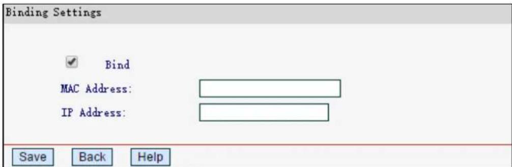
- Enter the MAC Address and IP Address and click Save.
- Select the Bind checkbox.
- Click Save.
To modify or delete an existing entry, follow the steps below.
- Find the desired entry in the table.
- Click Edit or Delete as desired on the Modify column.
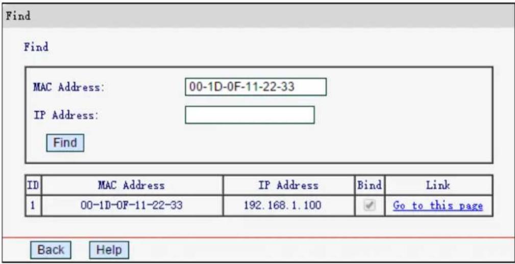
To find an existing entry, follow the steps below.
- Click Find.
- Enter the MAC Address or IP Address.
- Click Find, and the result will be displayed in the table below.
4.12.2 ARP List
Go to IP & MAC Binding→ARP List, you can view and set the IP & MAC Binding entries.
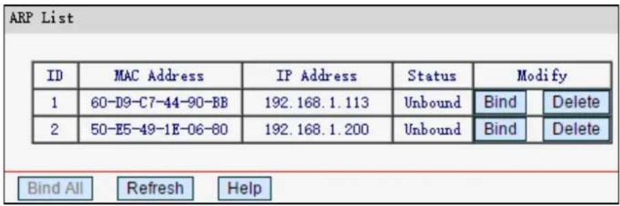
MAC Address - The MAC address of the controlled computer in the LAN.
IP Address - The assigned IP address of the controlled computer in the LAN.
➢ Status - Indicates whether or not the MAC and IP addresses are bound.
Configure - Load or delete an item.
- Bind - Load the item to the IP & MAC Binding list.
- Delete - Delete the item.
Click Bind All to bind all the current items, available after enable.
Click Refresh to refresh all items.
4.13 Dynamic DNS
Choose Dynamic DNS, and you can configure the Dynamic DNS function.
The router offers the DDNS (Dynamic Domain Name System) feature, which allows the hosting of a website, FTP server, or e-mail server with a fixed domain name (named by yourself) and a
dynamic IP address, and then your friends can connect to your server by entering your domain name no matter what your IP address is.
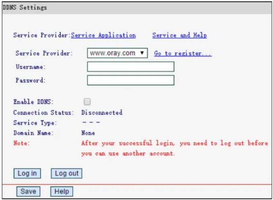
Service Provider - Dynamic DNS service providers.
Username - The username for your DDNS account.
➢ Password - The Password for your DDNS account.
Enable DDNS - Select if you want to enable this feature.
➢ Connection Status - Displays the status of the DDNS service connection.
➢ Domain Name - The domain name you received from dynamic DNS service provider.
Click Log in to log in to the DDNS service.
Click Log out to log out of the DDNS service.
4.14 System Tools
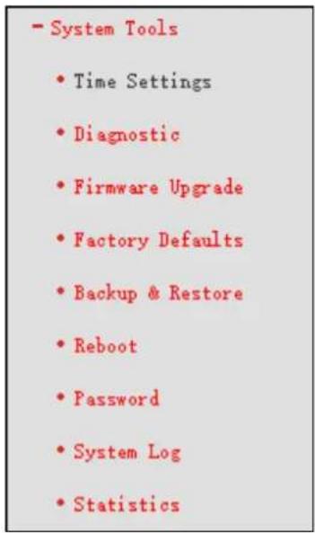
Choose System Tools, and you can see the submenus under the main menu: Time Settings, Diagnostic, Firmware Upgrade, Factory Defaults, Backup & Restore, Reboot, Password, System Log and Statistics. Click any of them, and you will be able to configure the corresponding function. The detailed explanations for each submenu are provided below.
4.14.1 Time Settings
Go to System Tools→Time Settings, you can configure the time according to your needs.
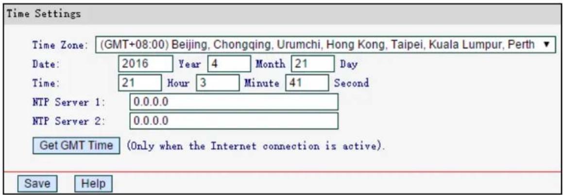
Time Zone - Select your local time zone from this drop-down list.
Date - Enter your local date in MM/DD/YY into the right blanks.
Time - Enter your local time in HH/MM/SS into the right blanks.
NTP Server 1/NTP Server 2 - Enter the address or domain of the NTP Server 1 or NTP Server 2, and then the router will get the time from the NTP Server preferentially.
Click Get GMT Time to get system time from Internet if you have connected to the Internet.
To set time manually:
- Select your local time zone.
- Enter the Date in Month/Day/Year format.
- Enter the Time in Hour/Minute/Second format.
- Click Save.
NOTE:
1) This setting will be used for some time-based functions such as firewall. You must specify your time zone once you login to the router successfully, otherwise these functions will not take effect.
2) The time will be lost if the router is turned off.
3) The router will automatically obtain GMT from the Internet if it is configured accordingly.
4.14.2 Diagnostic
Go to System Tools→Diagnostic, you can use Ping or Tracert to check connectivity of your network.
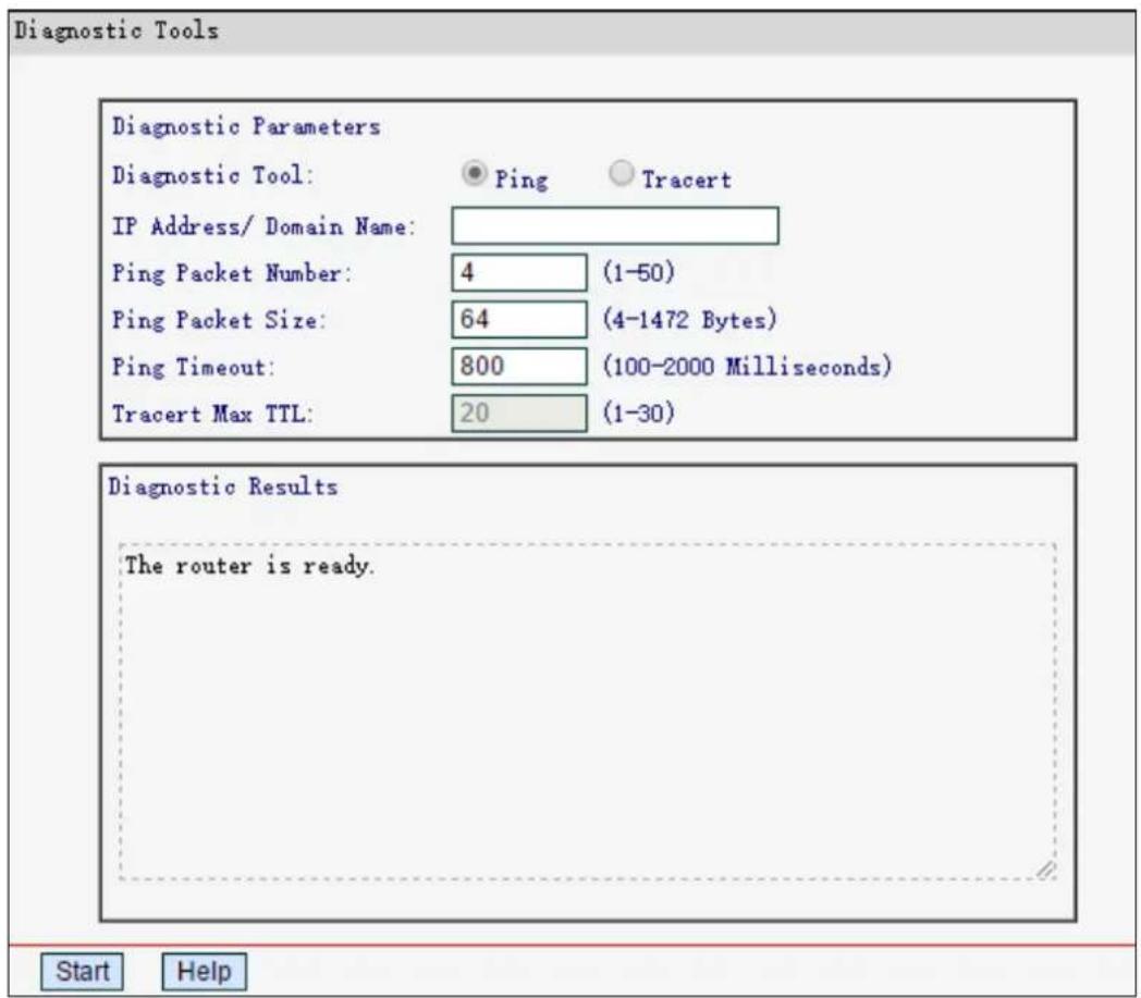
Diagnostic Tool - Select one diagnostic tool.
- Ping - This diagnostic tool troubleshoots connectivity, reachability, and name resolution to a given host or gateway.
- Tracert - This diagnostic tool tests the performance of a connection.
IP Address/Domain Name - Enter the destination IP address or domain name used for network connection test.
Pings Packet Number - The number of Ping packets for a Ping connection.
➢ Ping Packet Size - The size of Ping packet.
Ping Timeout - Set the waiting time for the reply of each Ping packet. If there is no reply in the specified time, the connection is overtime.
Tracert Max TTL - The max number of hops for a Tracert connection.
Click Start to check the connectivity of the Internet.
The Diagnostic Results page displays the result of diagnosis.
NOTE:
Only one user can usethis tool at one time. Options Ping Packet Number, Ping Packet Size a Ping Timeout are used for Ping function. Option Tracert Max TTL is used for Tracert function
4.14.3 Firmware Upgrade
Go to System Tools→Firmware Upgrade, you can update the latest version of firmware for the router.
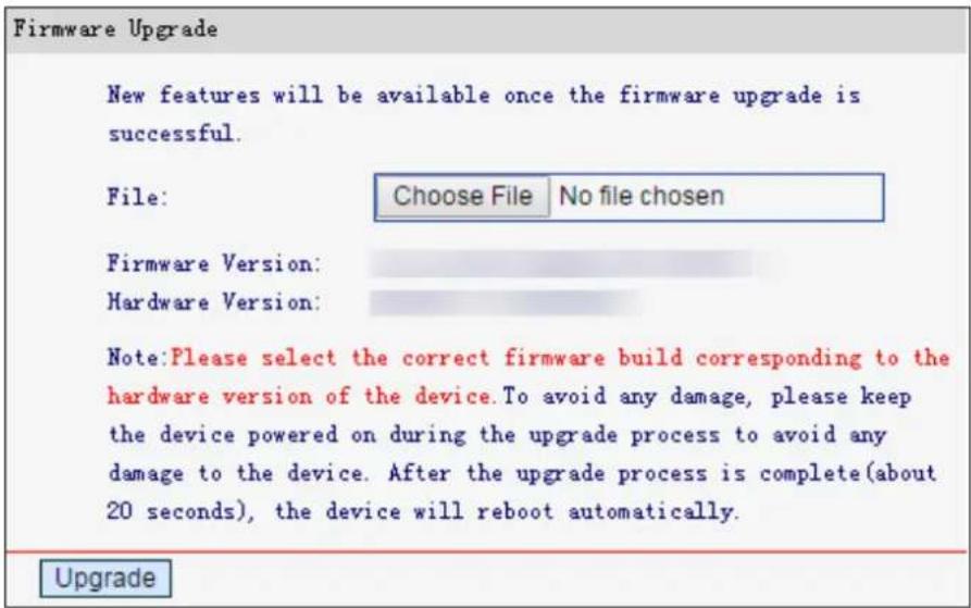
Firmware Version - This displays the current firmware version.
Hardware Version - This displays the current hardware version. The hardware version of the upgrade file must accord with the router's current hardware version.
To upgrade the router's firmware, follow the steps below:
- Download a more recent firmware upgrade file from the official website (http://www.mercusys.com).
- Click Choose File to locate and open the update file.
- Click Upgrade.
- The router will reboot after the upgrading has been finished.
NOTE:
1) When you upgrade the router's firmware, you may lose its current configurations. So befe upgrading the firmware, please backup your current settings to the local computer.
2) To avoid any damage, keep the router powered on during the upgrade process.
4.14.4 Factory Defaults
Go to System Tools Factory Defaults, and you can restore the configurations of the router to factory defaults on the following screen

Click Restore to reset all configuration settings to their default values.
• The default IP Address: 192.168.1.1
• The default Subnet Mask: 255.255.255.0
NOTE:
Any settings you have saved will be lost when the default settings are restored.
4.14.5 Backup & Restore
Go to System Tools-Backup & Restore" you can save the current configuration of the router as a backup file and restore the configuration via a backup file as shown below.
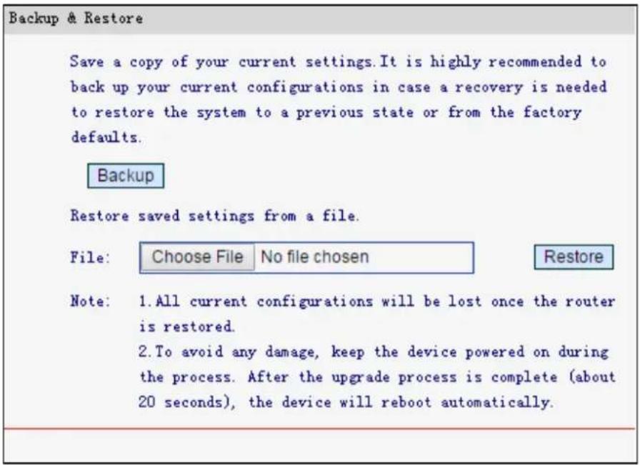
Click Backup to save all configuration settings as a backup file in your local computer.
To upgrade the router's configuration, follow these instructions.
- Click Choose File to locate and open the update file for the router.
- Click Restore.
NOTE:
The current configuration will be covered by the uploading configuration file. Eupgrade process lasts for 20 seconds and the router will reboot automatically. Keep the router powered on during the process to prevent any damage.
4.14.6 Reboot
Go to System Tools→Reboot, you can click Reboot to reboot the router via the next screen.

Some settings of the router will take effect only after rebooting, which include
- Change the LAN IP Address (system will reboot automatically).
• Change the DHCP Settings.
• Change the wireless configurations.
• Change the web management port. -
Upgrade the firmware of the router (system will reboot automatically).
-
Restore the router's settings to factory defaults (system will reboot automatically).
- Update the configuration with the file (system will reboot automatically.
4.14.7 Password
Go to System Tools→Password, you can change the password of the web management page.
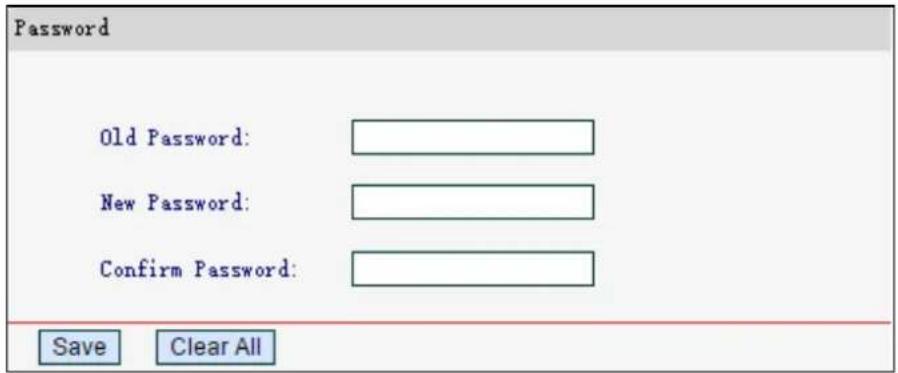
Click Save to make the settings effective.
Click Clear All to clear all information you have entered.
4.14.8 System Log
Go to System Tools→System Log, you can view the logs of the router.
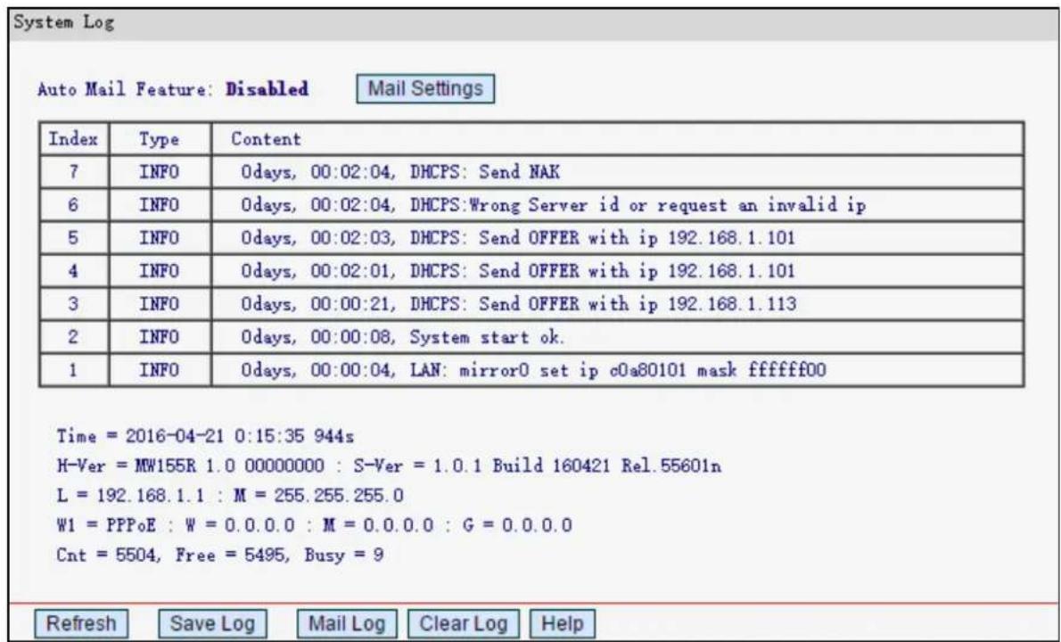
Auto Mail Feature - Indicates whether auto mail feature is enabled or not.
Mail Settings - Set the receiving and sending mailbox address, server address, and the timetable for Auto Mail Feature, as shown below.
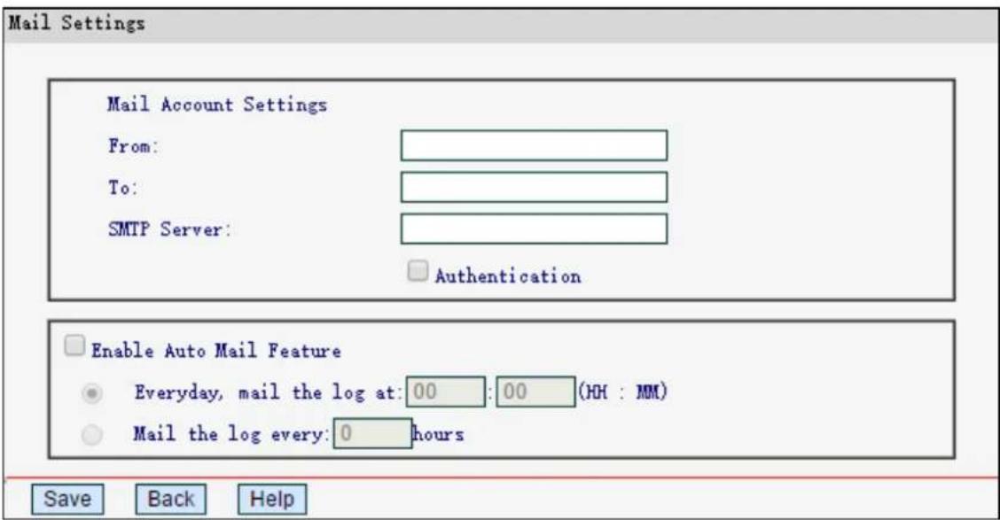
- From - Your mail box address. The router would connect it to send logs.
- To - Recipient's address. The destination mailbox where the logs would be received.
- SMTP Server - Your smtp server. It corresponds with the mailbox filled in the From field. You can log on the relevant website for Help if you are not clear with the address.
- Authentication - Most SMTP Server requires Authentication. It is required by most mailboxes that need User Name and Password to log in.
NOTE:
Only when you select Authentication, do you have to enter the Username and Password in the following fields.
- Username - Your mail account name filled in the From field.
- Password - Your mail account password.
- Confirm Password - Enter the password again to confirm.
- Enable Auto Mail Feature - Select to mail logs automatically. You could mail the current logs either at a specified time everyday or by intervals, but only one could be the current effective rule. Enter the desired time or intervals in the corresponding field.
Click Save to make your settings effective.
Click Back to return to the previous page.
Click Refresh to show the latest log list.
Click Save Log to save all the logs in a txt file.
Click Mail Log to send an email of current logs manually according to your Mail settings.
Click Clear Log to delete all logs from the router permanently, not just from the page.
4.14.9 Statistics
Go to System Tools → Statistics, you can view the network traffic of each PC on the LAN.
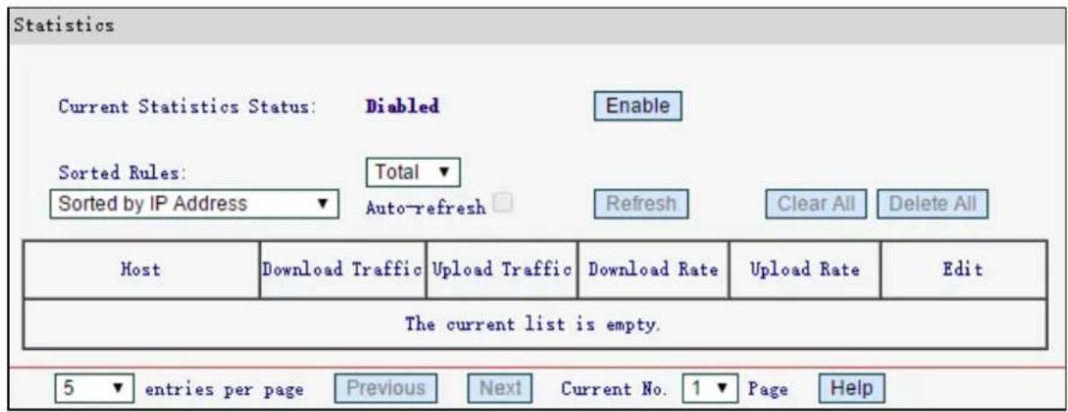
Current Statistics Status - Enabled or Disabled. The default value is disabled. You can click Enable to enable the feature.
Sorted Rules - Choose how displayed statistics are sorted
Select Auto-refresh to refresh automatically.
Click Refresh to refresh the page manually.
Click Clear All to reset the values of all the entries to zero.
Click Delete All to delete all entries in the table.
Host - Displays the IP Address/ MAC Address of the host.
Download Traffic - The total number of bytes received by the router.
Upload Traffic - The total number of bytes sent by the router.
➢ Download Rate - The number of bytes received per second by the router.
Upload Rate - The number of bytes sent per second by the router.
Click Next to go to the next page or click Previous to return to the previous page.
Appendix A: FAQ
T1. What can I do if I forget my password?
1) For wireless password: By default, the wireless network has no password. If you have set password for the network, log in to the router's web management page, go to Wireless→Basic Settings to obtain or reset your password.
2) For the web management page password: Restore the router to its factory default settings and then create a new password when prompted.
T2. How do I restore my modem router's configuration to its factory default settings?
There are two ways to reset the modem router.
Method one: With the router powered on, press and hold the WPS/RESET button for at least 5 seconds until all LEDs turn on momentarily. And then release the button and wait the router to reboot to its factory default settings.
Method two: Restore the default setting from System Tools→ Factory Defaults of the router's web management page.
NOTE:
Once the modem router is reset, the current configuration settings will be lost and you will need to re-configure the router.
T3. What can I do if I cannot log in to the router's web management page?
This can happen for a variety of reasons, please try the methods below.
1) Make sure the router connects to the computer correctly and the corresponding LED indicator(s) light up.
2) Make sure the IP address of your computer is configured as Obtain an IP address automatically and Obtain DNS server address automatically.
3) Make sure http://mwlogin.net is correctly entered.
4) Check your computer's settings:
1) Go to Start→Control Panel→Network and Internet, and click View network status and tasks;
2) Click Internet Options on the bottom left;
3) Click Connections, and select Never dial a connection;
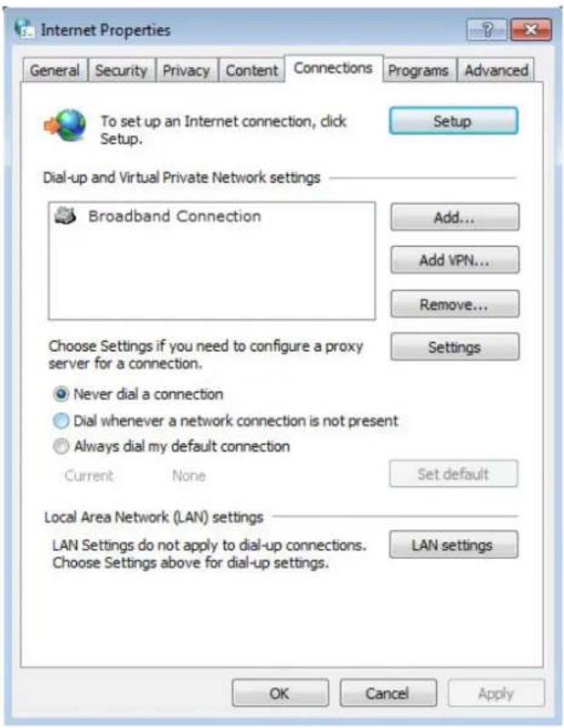
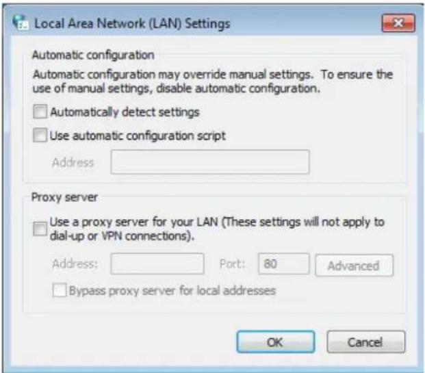
4) Click LAN settings, deselect the following three options and click OK;
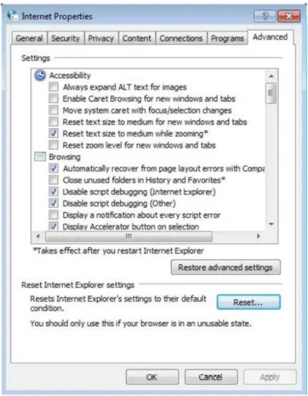
5) Go to Advanced→Restore advanced settings, and click OK to save the settings.
Change a web browser or computer and log in again.
➢ Reset the modem router to factory default settings.
Note: You'll need to reconfigure the router to surf the Internet once the router is reset.
T4. What can I do if I cannot access the Internet?
1) Make sure the router connects to the computer correctly and the corresponding LED indicator(s) light up.
2) Check to see if you can log in to the web management page of the router. If you can, try the following steps. If you cannot, please set your computer by referring to T3 and then try to see if you can access the Internet. If the problem persists, please go to the next step.
3) Make sure you have selected the proper WAN Connection Type and entered the parameters correctly.
4) Go to Network→MAC Clone to clone the MAC address.
5) If you still cannot access the Internet, please restore your router to its factory default settings and reconfigure your modem router by following the instructions in Chapter 3 Quick Installation Guide.
6) Please feel free to contact our Technical Support if the problem still exists.
Appendix B: Configuring the PC
In this section, we'll introduce how to install and configure the TCP/IP correctly in Windows 7. First make sure your Ethernet Adapter is working, refer to the adapter's manual if needed.
1. Install TCP/IP component
1) On the Windows taskbar, click the Start button, and then click Control Panel.
2) Click the Network and Internet, and click the Network and Sharing Center, then click Change adapter settings.
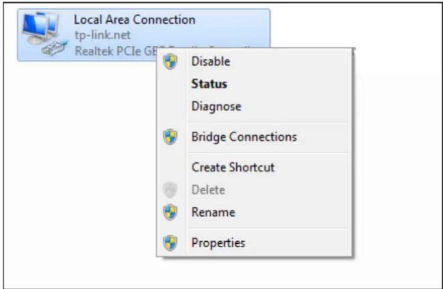
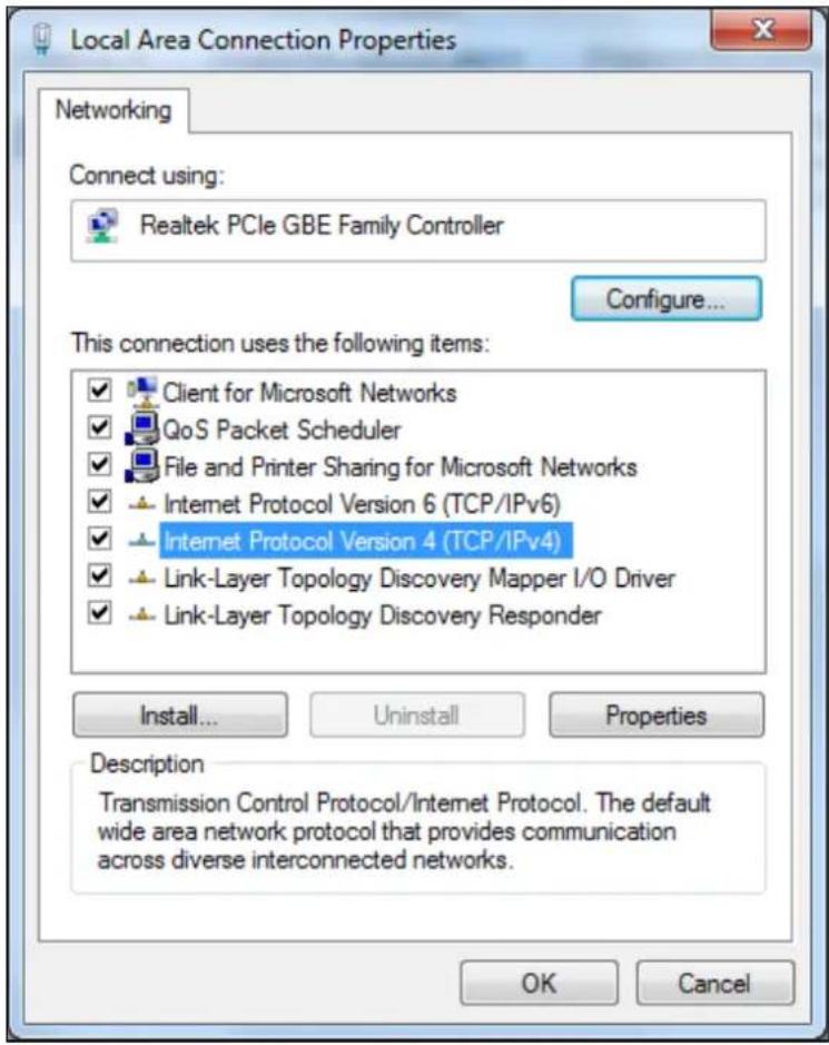
3) Right click the icon that showed below, select Properties on the prompt page.
4) In the prompt page that showed below, double click on the Internet Protocol Version 4 (TCP/IPv4).
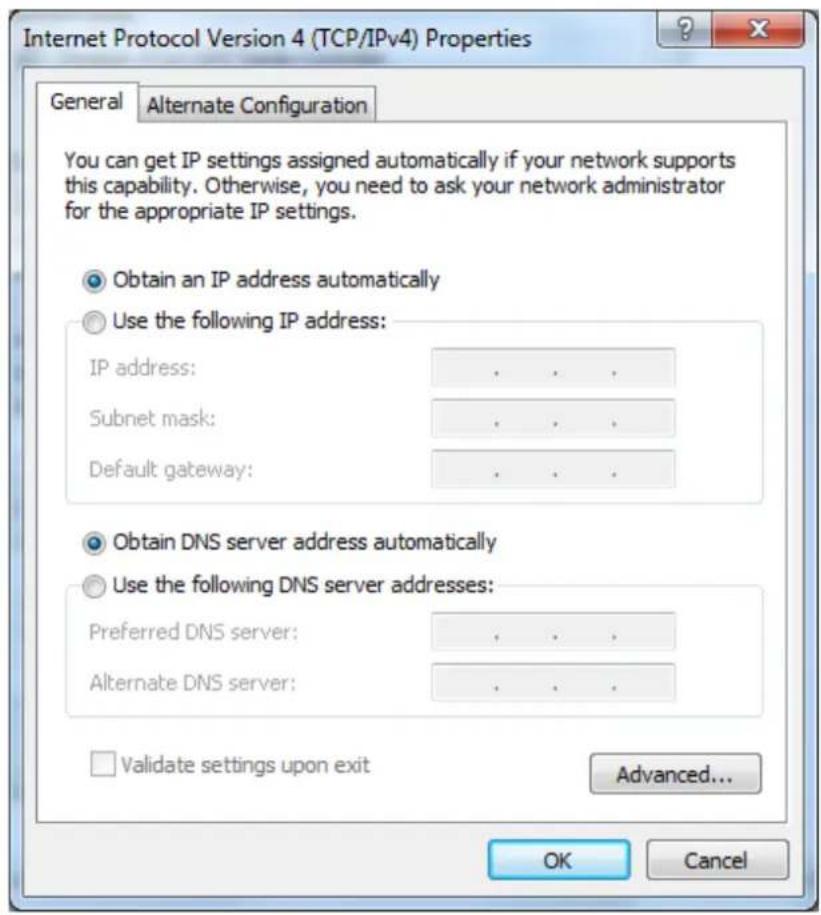
5) The following TCP/IP Properties window will display and the IP Address tab is open on this window by default.
Now you have two ways to configure the TCP/IP protocol below:
Setting IP address automatically
Select Obtain an IP address automatically, Choose Obtain DNS server automatically, as shown in the figure below:
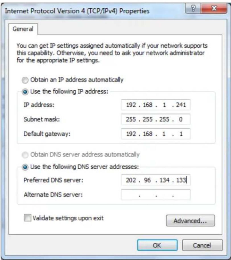
Setting IP address manually
1 Select Use the following IP address radio button. And the following items are available
2 If the router's LAN IP address is 192.168.1.1, specify the IP address as 192.168.1.x (x is from 2 to 254), and Subnet mask is 255.255.255.0.
3 Type the router's LAN IP address (the default IP is 192.168.1.1) into the Default gateway field.
4 Select Use the following DNS server addresses radio button. In the Preferred DNS Server field you can type the DNS server IP address, which has been provided by your ISP.