
SCv320 - Disk array DELL - Free user manual and instructions
Find the device manual for free SCv320 DELL in PDF.


| Product Type | Dell SCv320 Disk Array |
| Form Factor | 2U rackmount |
| Drive Bays | 12 x 2.5" hot-swappable |
| Supported Drives | SAS/SATA SSD or HDD |
| Max Raw Capacity | Up to 96 TB (12 x 8 TB HDD) |
| Controllers | Dual active-active, hot-swappable |
| Host Interfaces | 4 x 10Gb iSCSI or 4 x 16Gb FC |
| Power Supplies | Dual redundant, hot-swappable, 580W each |
| Cooling | Dual fan modules |
| Dimensions (HxWxD) | 3.44 x 17.98 x 20.75 in (87.3 x 456.5 x 527 mm) |
| Weight | 52.4 lbs (23.8 kg) fully loaded |
| Power Consumption | 500W typical |
| RAID Levels | 0, 1, 5, 6, 10, 50, 60 |
| Management | Dell Storage Manager |
| Expansion | Supports SCv320 expansion enclosures |
| Operating Temperature | 10°C to 35°C (50°F to 95°F) |
| Operating Humidity | 10% to 90% non-condensing |
| Certifications | FCC, CE, UL, VCCI |
| Maintenance | Clean with dry cloth; avoid liquids |
| Safety | Use grounded outlets; do not block vents |
Frequently Asked Questions - SCv320 DELL
User questions about SCv320 DELL
0 question about this device. Answer the ones you know or ask your own.
Ask a new question about this device
Download the instructions for your Disk array in PDF format for free! Find your manual SCv320 - DELL and take your electronic device back in hand. On this page are published all the documents necessary for the use of your device. SCv320 by DELL.
USER MANUAL SCv320 DELL
Dell SCv300 and SCv320 Expansion Enclosure Owner's Manual
Notes, Cautions, and Warnings

NOTE: A NOTE indicates important information that helps you make better use of your product.

CAUTION: A CAUTION indicates either potential damage to hardware or loss of data and tells you how to avoid the problem.

WARNING: A WARNING indicates a potential for property damage, personal injury, or death.
Copyright © 2017 Dell Inc. or its subsidiaries. All rights reserved. Dell, EMC, and other trademarks are trademarks of Dell Inc. or its subsidiaries. Other trademarks may be trademarks of their respective owners.
2017 - 10
Rev. A
Contents
About this Guide....4
Revision History....4
Audience....4
Contacting Dell....4
Related Publications....4
1 About the SCv300 and SCv320 Expansion Enclosure.... 5
SCv300 and SCv320 Expansion Enclosure Overview....5
SCv300 and SCv320 Expansion Enclosure Monitoring and Diagnostics.... 5
SCv300 and SCv320 Expansion Enclosure Front-Panel Features and Indicators....5
SCv300 and SCv320 Expansion Enclosure Back-Panel Features and Indicators....6
SCv300 and SCv320 Expansion Enclosure EMM Features and Indicators....7
EMM Failover 7
SCv300 and SCv320 Expansion Enclosure Drives....8
2 Replacing SCv300 and SCv320 Expansion Enclosure Components.... 9
Safety Precautions....9
Installation Safety Precautions....9
Electrical Safety Precautions....9
Electrostatic Discharge Precautions....10
General Safety Precautions....10
Pre-Replacement Procedures....10
Send Diagnostic Data Using Dell SupportAssist....10
Change the Operation Mode of the Storage Center to Maintenance....10
Replacing the Front Bezel....11
Replacing Hard Drives 11
SCv300 and SCv320 Expansion Enclosure Drive Numbering....11
Identify the Failed Hard Drive....12
Replace a Hard Drive....13
Replacing Rack Rails....15
Post-Replacement Procedures....16
Send Diagnostic Data Using Dell SupportAssist.... 16
Change the Operation Mode of the Storage Center to Normal....16
3 Troubleshooting SCv300 and SCv320 Components.... 17
Troubleshooting Power Supply/Cooling Fan Modules....17
Troubleshooting Hard Drives....17
Troubleshooting Enclosure Management Modules....17
Troubleshooting the Control Panel....18
4 SCv300 and SCv320 Expansion Enclosure Technical Specifications.... 19
Technical Specifications....19
About this Guide
This guide describes how to perform service and maintenance on the SCv300 and SCv320 expansion enclosure.
Revision History
Document Number: 680-142-001
Revision Date Description
A October 2017 Initial release
Audience
The information provided in this guide is intended for use by Dell end users.
Contacting Dell
Dell provides several online and telephone-based support and service options. Availability varies by country and product, and some services might not be available in your area.
To contact Dell for sales, technical support, or customer service issues, go to www.dell.com/support.
• For customized support, type your system service tag on the support page and click Submit.
- For general support, browse the product list on the support page and select your product.
Related Publications
The following documentation is available for the SCv300 and SCv320 expansion enclosure.
- Dell Storage Center SCv300 and SCv320 Expansion Enclosure Getting Started Guide Provides information about an SCv300/SCv320 expansion enclosure, such as installation instructions and technical specifications.
- Dell Storage Center Software Update Guide Describes how to update Storage Center software from an earlier version to the current version.
- Dell Storage Center Command Utility Reference Guide Provides instructions for using the Storage Center Command Utility. The Command Utility provides a command-line interface (CLI) to enable management of Storage Center functionality on Windows, Linux, Solaris, and AIX platforms.
- Dell Storage Center Command Set for Windows PowerShell Provides instructions for getting started with Windows PowerShell cmdlets and scripting objects that interact with the Storage Center using the PowerShell interactive shell, scripts, and PowerShell hosting applications. Help for individual cmdlets is available online.
- Dell Storage Manager Administrator's Guide Provides instructions for using the Data Collector Manager and the Dell Storage Manager Client.
- Dell TechCenter Provides technical white papers, best practice guides, and frequently asked questions about Dell Storage products. Go to http://en.community.dell.com/techcenter/storage/.
About the SCv300 and SCv320 Expansion Enclosure
An SCv300 and SCv320 expansion enclosure provides expansion storage for a Dell Storage Center.
The SCv300 and SCv320 expansion enclosure connects directly to the SAS ports on the back of the storage system.
SCv300 and SCv320 Expansion Enclosure Overview
The SCv300 is a 2U expansion enclosure that supports up to 12 3.5-inch hard drives installed in a four-column, three-row configuration. The SCv320 is a 2U expansion enclosure that supports up to 24 2.5-inch hard drives installed vertically side by side. An SCv300 and SCv320 expansion enclosure ships with two redundant power supply/cooling fan modules and two redundant enclosure management modules (EMMs).
SCv300 and SCv320 Expansion Enclosure Monitoring and Diagnostics
The Storage Center OS generates alert messages for temperature, I/O module, fan module, disk, and power conditions for Storage Center components. Use the Dell Storage Manager to view these alerts.
LED indicators on the expansion enclosure also notify you of possible problems.
SCv300 and SCv320 Expansion Enclosure Front-Panel Features and Indicators
The front panel shows the expansion enclosure status and power supply status.
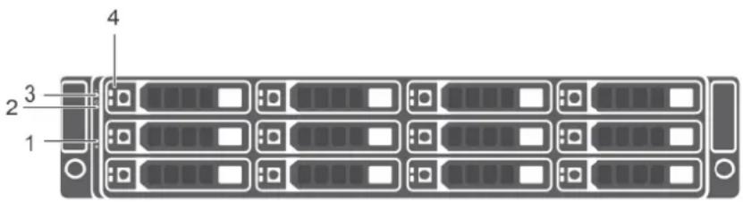
Figure 1. SCv300 Front-Panel Features and Indicators
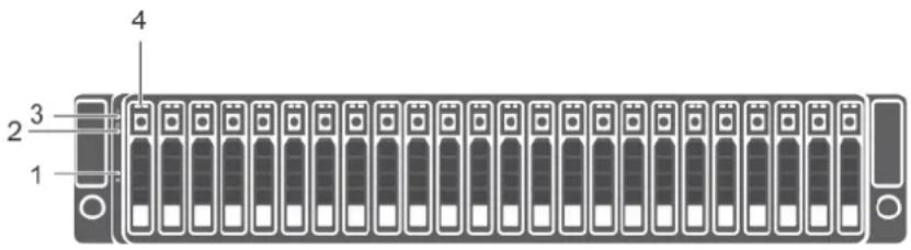
Figure 2. SCv320 Front-Panel Features and Indicators
Item Name Icon Description
| 1 System identification button | i | The system identification button on the front control panel can be used to locate a particular expansion enclosure within a rack. When the button is pressed, the system status indicators on the control panel and the Enclosure Management Module (EMM) blink blue until the button is pressed again. |
| 2 Power LED The power LED lights when at least one power supply unit is supplying power to the expansion enclosure. | ||
| 3 Expansion enclosure status LED | - | The expansion enclosure status LED lights when the expansion enclosure power is on.Solid blue during normal operation.Blinks blue when a host server is identifying the expansion enclosure or when the system identification button is pressed.Blinks amber or remains solid amber for a few seconds and then turns off when the EMMs are starting or resetting.Blinks amber for an extended time when the expansion enclosure is in a warning state.Remains solid amber when the expansion enclosure is in the fault state. |
| 4 Hard disk drives | SCv300 – Up to 12 3.5-inch SAS hot-swappable hard disk drives.SCv320 – Up to 24 2.5-inch SAS hot-swappable hard disk drives. | |
SCv300 and SCv320 Expansion Enclosure Back-Panel Features and Indicators
The back panel provides controls to power up and reset the expansion enclosure, indicators to show the expansion enclosure status, and connections for back-end cabling.
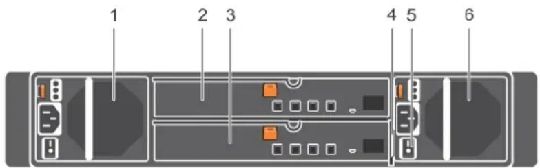
Figure 3. SCv300 and SCv320 Expansion Enclosure Back Panel Features and Indicators
| Item | Name Description | |
| 1 | Power supply unit and cooling fan module (PS1) | 600 W power supply |
| 2 | Enclosure management module (EMM 0) | The EMM provides a data path between the expansion enclosure and the storage controllers. The EMM also provides the management functions for the expansion enclosure. |
| 3 | Enclosure management module (EMM 1) | The EMM provides a data path between the expansion enclosure and the storage controllers. The EMM also provides the management functions for the expansion enclosure. |
| 4 | Information tag A slide-out label panel that records system information such as the Service Tag | |
Item Name Description
5 Power switches (2) Controls power for the expansion enclosure. There is one switch for each power supply.
6 Power supply unit and cooling fan module (PS2) 600 W power supply
SCv300 and SCv320 Expansion Enclosure EMM Features and Indicators
The SCv300 and SCv320 includes two enclosure management modules (EMMs) in two interface slots.
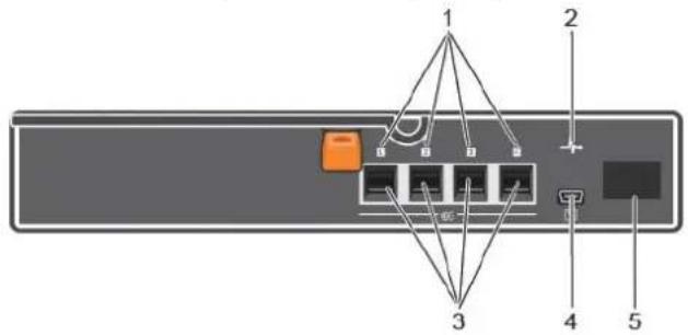
Figure 4. SCv300 and SCv320 Expansion Enclosure EMM Features and Indicators
| Item | Name Icon Description | |
| 1 SAS port status(1-4) | · Green: All the links to the port are connected· Amber: One or more links are not connected· Off: Expansion enclosure is not connected | |
| 2 EMM status indicator | · On steady green: Normal operation· Amber: Expansion enclosure did not boot or is not properly configured· Blinking green: Automatic update in progress· Blinking amber (two times per sequence): Expansion enclosure is unable to communicate with other expansion enclosures· Blinking amber (four times per sequence): Firmware update failed· Blinking amber (five times per sequence): Firmware versions are different between the two EMMs | |
| 3 SAS ports 1-4 (Input or Output) | Provides SAS connections for cabling the storage controller to the next expansion enclosure in the chain. (Single Port, Redundant, and Multi-chain Configuration). | |
| 4 USB Mini-B (serial debug port) | Not for customer use. | |
| 5 Unit ID display Displays the enclosure ID. | ||
EMM Failover
Control and monitoring of the expansion enclosure elements can be transferred from one EMM to another in the event of an EMM failure.
In the event of an EMM failure, the functioning EMM activates the amber status LED of the failed EMM. The functioning EMM then manages all aspects of the expansion enclosure, including monitoring and controlling the expansion enclosure LEDs, power supply units, and fans.
SCv300 and SCv320 Expansion Enclosure Drives
Dell Enterprise Plus hard disk drives (HDDs) and Dell Enterprise Plus solid-state drives (SSDs) are the only drives that can be installed in SCv300 and SCv320 expansion enclosures. If a non-Dell Enterprise Plus drive is installed, the Storage Center prevents the drive from being managed.
The drives in an SCv300 expansion enclosure are installed horizontally. The drives in an SCv320 expansion enclosure are installed vertically. The indicators on the drives provide status and activity information.
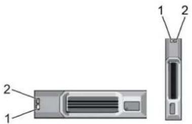
Figure 5. SCv300 and SCv320 Expansion Enclosure Drive Indicators
Item Name Indicator Code
1 Drive activity indicator
- Blinking green: Drive activity
- Steady green: Drive is detected and there are no faults
2 Drive status indicator
- Steady green: Normal operation
- Blinking green (two times per second): Drive identification is enabled
- Blinking amber (three times per second): Hard disk drive failure
- Off: No power to the drive
Replacing SCv300 and SCv320 Expansion Enclosure Components
This chapter describes how to remove and install components of the SCv300 and SCv320 expansion enclosure.
This information assumes that you have received the replacement component and are ready to install it.
Safety Precautions
Always follow these safety precautions to avoid injury and damage to Storage Center equipment.
If equipment described in this guide is used in a manner not specified by Dell, the protection provided by the equipment could be impaired. For your safety and protection, observe the rules described in the following sections.

NOTE: See the safety and regulatory information that shipped with each Storage Center component. Warranty information is included as a separate document.
Installation Safety Precautions
Follow these safety precautions when installing an SCv300 and SCv320 expansion enclosure:
- Dell recommends that only individuals with rack-mounting experience install an SCv300 and SCv320 expansion enclosure in a rack.
- The rack construction must support the total weight of the installed expansion enclosures. The design should incorporate stabilizing features suitable to prevent the rack from tipping or being pushed over during installation or in normal use.
- To prevent the rack from tipping, slide only one expansion enclosure out of the rack at a time.
- Make sure that the expansion enclosure is always fully grounded to prevent damage from electrostatic discharge.
- When handling the expansion enclosure components, use an electrostatic wrist guard or a similar form of protection.
Electrical Safety Precautions
Always follow electrical safety precautions to avoid injury and damage to Storage Center equipment.

WARNING: Disconnect power from the expansion enclosure when removing or installing components that are not hot-swappable. When disconnecting power, first power down the storage system using the storage client and then unplug the power cords from the power supplies in the storage system and expansion enclosure.
- Provide a suitable power source with electrical overload protection. All Storage Center components must be grounded before applying power. Make sure that a safe electrical earth connection can be made to power supply cords. Check the grounding before applying power.
- The plugs on the power supply cords are used as the main disconnect device. Make sure that the socket outlets are located near the equipment and are easily accessible.
- Know the locations of the equipment power switches and the room's emergency power-off switch, disconnection switch, or electrical outlet.
- Do not work alone when working with high-voltage components.
- Use rubber mats specifically designed as electrical insulators.
- Do not remove covers from the power supply unit. Disconnect the power connection before removing a power supply from the expansion enclosure.
- Do not remove a faulty power supply unless you have a replacement model of the correct type ready for insertion.
- Unplug the expansion enclosure chassis before you move it or if you think it has become damaged in any way. When powered by multiple AC sources, disconnect all power sources for complete isolation.
Electrostatic Discharge Precautions
Always follow electrostatic discharge (ESD) precautions to avoid injury and damage to Storage Center equipment.
Electrostatic discharge (ESD) is generated by two objects with different electrical charges coming into contact with each other. The resulting electrical discharge can damage electronic components and printed circuit boards. Follow these guidelines to protect your equipment from ESD:
• Dell recommends that you always use a static mat and static strap while working on components in the interior of the chassis.
- Observe all conventional ESD precautions when handling plug-in modules and components.
- Use a suitable ESD wrist or ankle strap.
- Avoid contact with backplane components and module connectors.
- Keep all components and printed circuit boards (PCBs) in their antistatic bags until ready for use.
General Safety Precautions
Always follow general safety precautions to avoid injury and damage to Storage Center equipment.
- Keep the area around the expansion enclosure chassis clean and free of clutter.
- Place any system components that have been removed away from the expansion enclosure chassis or on a table so that they are not in the way of other people.
- While working on the expansion enclosure chassis, do not wear loose clothing such as neckties and unbuttoned shirt sleeves. These items can come into contact with electrical circuits or be pulled into a cooling fan.
- Remove any jewelry or metal objects from your body. These items are excellent metal conductors that can create short circuits and harm you if they come into contact with printed circuit boards or areas where power is present.
- Do not lift the expansion enclosure chassis by the handles of the power supply units (PSUs). They are not designed to hold the weight of the entire chassis, and the chassis cover could become bent.
- Before moving the expansion enclosure chassis, remove the PSUs to minimize weight.
- Do not remove drives until you are ready to replace them.

NOTE: To ensure proper expansion enclosure cooling, hard drive blanks must be installed in any hard drive slot that is not occupied.
Pre-Replacement Procedures
Perform the procedures described in this chapter before replacing a component of the SCv300 and SCv320 expansion enclosure.
Send Diagnostic Data Using Dell SupportAssist
Before replacing components, use Dell SupportAssist to send diagnostic data to Dell Technical Support Services.
- Use Dell Storage Manager to connect to the Storage Center.
-
In the Summary tab, click Send SupportAssist Information Now, which is located under SupportAssist Actions in the Status pane.
The Send SupportAssist Information Now dialog box opens. -
Select Storage Center Configuration and Detailed Logs.
-
Click OK.
Change the Operation Mode of the Storage Center to Maintenance
Change the operation mode of the Storage Center to Maintenance before replacing components.
- Use Dell Storage Manager to connect to the Storage Center.
-
In the Summary tab, click Edit Settings. The Edit Storage Center Settings dialog box opens.
-
Click the General tab.
- In the Operation Mode field select Maintenance. Selecting Maintenance isolates alerts from those that would occur during normal operation.
- Click OK.
Replacing the Front Bezel
The front bezel is a cover for the front panel of the expansion enclosure.
About this task
The front bezel must be removed from the front panel when replacing hard drives.
Steps
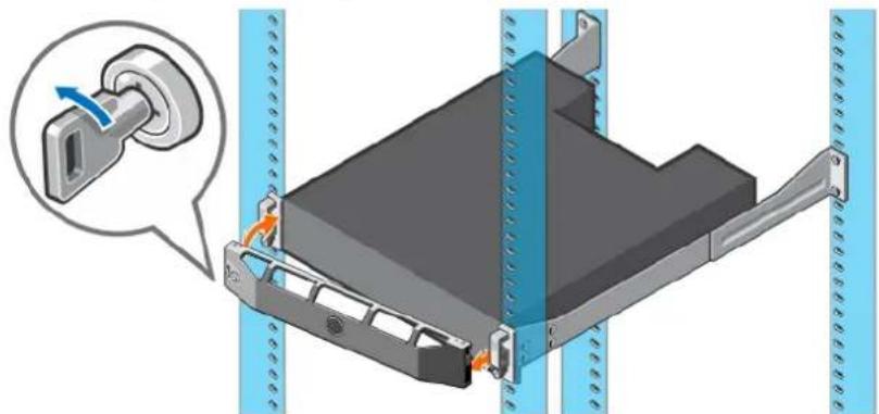
- Use the system key to unlock the keylock at the left end of the bezel.
- Lift the release latch next to the keylock.
- Rotate the left end of the bezel away from the front panel.
- Unhook the right end of the bezel and pull the bezel away from the expansion enclosure.
natural_image
3D diagram of a mechanical assembly with a knob inserted, showing internal components and alignment lines (no text or symbols)Figure 6. Replacing the Front Bezel
- Hook the right end of the replacement bezel onto the front panel of the expansion enclosure.
- Insert the left end of the bezel into the securing slot until the release latch locks into place.
- Secure the bezel with the keylock.
Replacing Hard Drives
The SCv300 and SCv320 expansion enclosures supports hot-swappable hard drives.
The SCv300 expansion enclosure supports up to 12 3.5-inch hard drives installed in a four-column, three-row configuration. The SCv320 expansion enclosure supports up to 24 2.5-inch hard drives installed vertically side-by-side. . Hard drives are connected to a backplane through hard drive carriers. Hard drive blanks are installed in the hard drive bays that are not occupied.

NOTE: One spare drive is allocated for every 20 drives in the expansion enclosure.
SCv300 and SCv320 Expansion Enclosure Drive Numbering
Drives are numbered from left to right in the SCv300 and SCv320 expansion enclosure.
The Storage Center identifies drives as XX-YY, where XX is the unit ID of the expansion enclosure, and YY is the drive position inside the expansion enclosure.
- The SCv300 holds up to 12 drives, which are numbered from left to right in rows starting from 0 at the top-left drive.


Figure 7. SCv300 Drive Numbering
- The SCv320 holds up to 24 drives, which are numbered from left to right starting from 0.

Figure 8. SCv320 Drive Numbering
Identify the Failed Hard Drive
To determine which hard drive failed, use the Dell Storage Manager Client.
- Use the Dell Storage Manager Client to connect to the Storage Center.
- Click the Hardware tab.
- In the Hardware tab navigation pane, select the Storage Center.
- In the Hardware Alerts area, find the hardware alert that identifies the expansion enclosure with the failed hard drive.
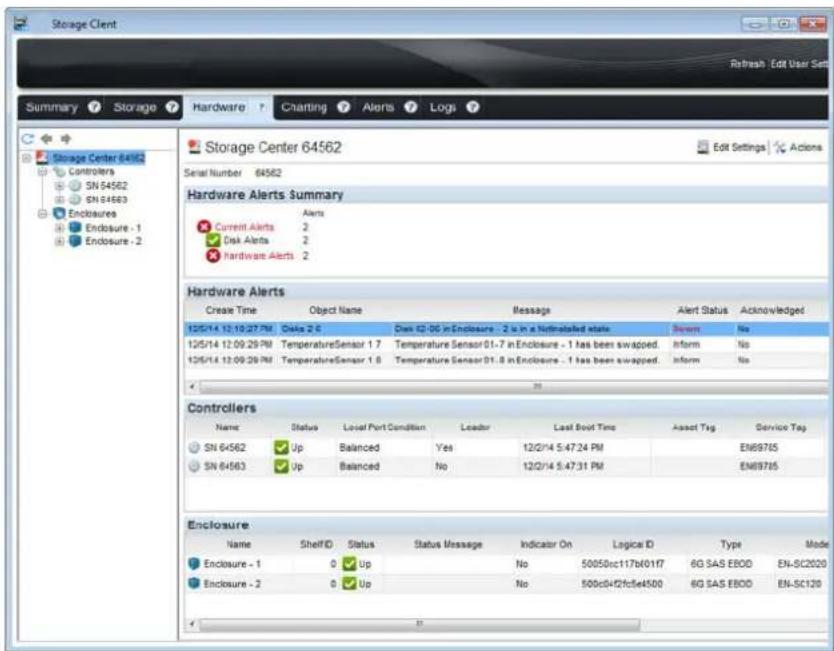
Figure 9. Hardware Alert Identifying the Expansion Enclosure with the Failed Hard Drive
- In the Hardware tab navigation pane, expand the expansion enclosure identified in the previous step.
- Select Disks. The status of each hard drive is displayed in the Disks tab.
- Select the failed hard drive. The location of the failed hard drive is displayed in the Disk View tab.
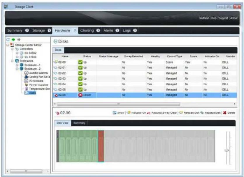
Figure 10. Front View of the Expansion Enclosure Showing the Failed Hard Drive
Replace a Hard Drive
Use this procedure to replace a failed hard drive.
Prerequisite
Use SupportAssist to send diagnostic data to Dell Technical Support Services.
About this task
Hard drives can be replaced without shutting down the expansion enclosure.

CAUTION: To prevent a storage system reset, at least one powered drive must remain installed in the primary chassis when multiple drives are replaced.
Steps
- Remove the front bezel.
A solid amber LED is lit on the failed hard drive. - Press the release button to open the hard drive carrier release handle.
- Slide the hard drive out until it is free of the hard drive slot.
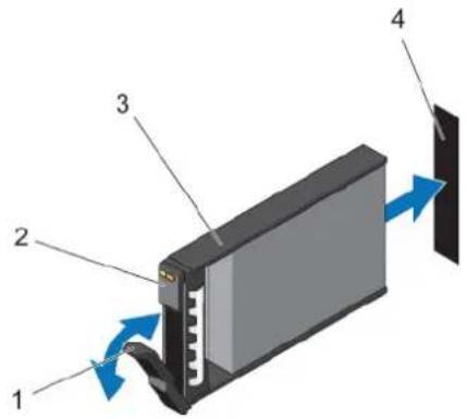
Figure 11. Replacing a Hard Drive
-
Hard drive carrier release handle 2. Hard drive indicators
-
Hard drive carrier 4. Hard drive slot
-
Press the release button on the replacement hard drive to open the hard drive carrier release handle.

NOTE: Hold the hard drive by the plastic part of the hard drive carrier or the handle.
- Insert the hard drive carrier into the hard drive slot until the carrier make contact with the backplane.

CAUTION: Do not remove the hard drive blanks that are installed in hard drive slots that are not occupied. The hard drive blanks ensure proper cooling of the expansion enclosure.
- Close the hard drive carrier handle to lock the hard drive in place.

NOTE: Allow several seconds for the expansion enclosure to recognize the hard drive and determine its status.
-
Replace the front bezel.
-
In Storage Manager, make sure that the replacement hard drive is recognized and shown as up and healthy.
Next step
Use SupportAssist to send diagnostic data to Dell Technical Support Services.
Installing Hard Drives in an SCv300 and SCv320 Expansion Enclosure
An SCv300 and SCv320 expansion enclosure is shipped with drives installed and empty drive blanks are inserted in the unused slots.
About this task
The following instructions describe the installation of Dell Enterprise hard drives for reference only.
Steps
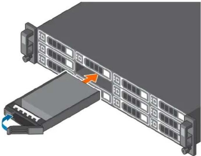
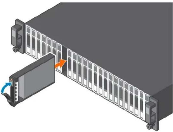
- Open the hard drive carrier handle and insert the hard drive carrier into the hard drive slot.
Start on the left side of the expansion enclosure with slot 0 and install drives from left to right.
- Slide the drive into the slot until the hard drive carrier contacts the backplane.
natural_image
3D illustration of a server rack with an open drive and a blue cable outlet, showing internal grid structure (no text or symbols)Figure 12. Installing Dell Enterprise Hard Drives in an SCv300
natural_image
3D illustration of a server rack with an open panel and a cable outlet, showing no text or symbols.Figure 13. Installing Dell Enterprise Hard Drives in an SCv320
- Close the hard drive carrier handle to lock the hard drive in place.
- Continue to push firmly until you hear a click and the hard drive carrier handle fully engages.
- Insert drive blanks into any open slots in the expansion enclosure.
All the drive slots in the expansion enclosure must be filled with a drive or drive blank.
Replacing Rack Rails
Rack rails are used to install SCv300 and SCv320 expansion enclosures into a rack.
Prerequisites
- Use SupportAssist to send diagnostic data to .
- Change the operation mode of the Storage Center to Maintenance.
About this task

NOTE: Replacing rack rails must be performed during a scheduled maintenance window when the Storage Center is unavailable to the network.
Steps
- Shut down the storage system and the expansion enclosure.
- Disconnect the power cables and SAS cables from the expansion enclosure.
- Remove the expansion enclosure from the rack rails.
- Remove the rack rails from the rack.
- Install the replacement rack rails in the rack.
- Install the expansion enclosure in the rack rails.
- Reconnect the power cables and SAS cables to the expansion enclosure.
- Start up the storage system and the expansion enclosure.
Next steps
- Change the operation mode of the Storage Center to Normal.
- Use SupportAssist to send diagnostic data to Dell Technical Support Services.

Post-Replacement Procedures
Perform the procedures described in this section after replacing a component of an SCv300 and SCv320 expansion enclosure.
Send Diagnostic Data Using Dell SupportAssist
After replacing components, use Dell SupportAssist to send diagnostic data to Dell Technical Support Services.
-
Use Dell Storage Manager to connect to the Storage Center.
-
In the Summary tab, click Send SupportAssist Information Now, which is located under SupportAssist Actions in the Status pane.
The Send SupportAssist Information Now dialog box opens.
-
Select Storage Center Configuration and Detailed Logs.
-
Click OK.
Change the Operation Mode of the Storage Center to Normal
Change the operation mode of the Storage Center to Normal after replacing components.
- Use Dell Storage Manager to connect to the Storage Center.
- In the Summary tab, click Edit Settings. The Edit Storage Center Settings dialog box opens.
- Click the General tab.
- In the Operation Mode field select Normal.
- Click OK.
Troubleshooting SCv300 and SCv320 Components
This section contains basic troubleshooting steps for components inside the SCv300 and SCv320 expansion enclosures.
Troubleshooting Power Supply/Cooling Fan Modules
Use these steps to troubleshoot power supply/cooling fan modules.
- Check the status of the power supply/cooling fan module using the Dell Storage Manager.
-
Determine the status of the power supply/cooling fan module LEDs.
-
If the power supply/cooling fan module fault indicator is lit, the power supply/cooling fan has failed.
-
If the AC power LED is not lit, check the power cord and power source into which the power supply is plugged:
-
Connect another device to the power source and check whether the device works.
- Connect the power cord to a different power source.
-
Replace the power cord.
-
Reseat the power supply/cooling fan module by removing and reinstalling it.

NOTE: Allow several seconds for the expansion enclosure to recognize the power supply/cooling fan module and determine its status.
Troubleshooting Hard Drives
Use these steps to troubleshoot hard drives.
- Check the status of the hard drive using the Dell Storage Manager.
-
Determine the status of the hard drive LEDs.
-
If the hard drive status LED blinks amber four times per second, the hard drive has failed.
-
If the hard drive status LED is not lit, proceed to the next step.
-
Check the connectors and reseat the hard drive.
a. Remove the hard drive.
b. Check the hard drive and the backplane to ensure that the connectors are not damaged.
c. Reinstall the hard drive. Make sure the hard drive contacts the backplane.
Troubleshooting Enclosure Management Modules
Use these steps to troubleshoot EMMs.
- Check the status of the EMM using the Dell Storage Manager.
- Check the pins and reseat the EMM.
a. Remove the EMM.
b. Verify that the pins on the backplane and the EMM are not bent.
c. Reinstall the EMM.
- Determine the status of the EMM link status LEDs. If the LEDs are not green, check the cables.
a. Reseat the cables on the expansion enclosure and the storage system.
b. Recheck the link status LEDs. If the link status LEDs are not green, replace the cables.
Troubleshooting the Control Panel
Use these steps to troubleshoot the control panel.
- Determine the status of the control panel LEDs. If the LEDs are not lit, and the enclosure is powered on, the control panel has failed.
- Reseat the control panel by removing and reinstalling it.

CAUTION: The storage system and expansion enclosures must be shut down before reseating the control panel.
SCv300 and SCv320 Expansion Enclosure Technical Specifications
Technical Specifications
The technical specifications of the SCv300 and SCv320 expansion enclosures are displayed in the following tables.
| Drives | |
| SAS hard drives | SCv300: Up to 12 hot-swappable 3.5-inch 12 Gbps SAS hard drives or SAS solid state drives (SSDs) |
| SCv320: Up to 24 hot-swappable 2.5-inch 12 Gbps SAS hard drives or SAS solid state drives (SSDs) | |
| NOTE: SCv300 and SCv320 expansion enclosures support self-encrypting drives (SEDs). | |
| Enclosure Management Modules (EMMs) |
| EMMs Two hot-swappable IO modules |
| Redundant Array of Independent Disks (RAID) |
| Controller Two hot-swappable storage controllers |
| Management RAID management using Dell Storage Manager |
| Back-Panel Connectors (per EMM) |
| SAS connectors Four mini-SAS HD connectors for connecting an expansion enclosure to a storage system. |
| NOTE: SAS connectors are SFF-8086/SFF-8088 compliant. |
| LED Indicators | |
| Front panel | One two-color LED indicator for system statusOne single-color LED indicator for power status |
| Hard-drive carrier | One single-color activity LEDOne two-color LED status indicator per drive |
| Power supply/cooling fan | Three LED status indicators for power supply status, power supply module status, and AC status |
| Power Supplies |
| AC power supply (per power supply) |
| Wattage 600 W |
| Voltage 100–240 VAC (8.6–4.3 A), autoranging, 50/60 Hz |
Power Supplies
Heat dissipation AC - 2047 BTU/hr
Available Hard Drive Power (per Slot)
| Supported hard drive power consumption (continuous) | Up to 1.2 A at +5 V, up to 0.5 A at +12 V |
Physical
| Height 8.7 cm (3.43 in.) | |
| Width 48.2 cm (18.98 in.) | |
| Depth | SCv300: 59.4 cm (23.39 in.) |
| SCv320: 54.1 cm (21.3 in.) | |
| Weight (maximum configuration) | SCv300: 28.59 kg (63.03 lb) |
| SCv320: 24.2 kg (53.35 lb) | |
| Weight without drives | SCv300: 9.0 kg (19.84 lb) |
| SCv320: 8.8 kg (19.4 lb) | |
Environmental

NOTE: For additional information about environmental measurements for specific configurations, see the Product Safety, EMC and Environmental Datasheets website.
Temperature
Operating SCv300: 5° to 35°C (41° to 95°F) with a maximum temperature gradation of 10°C (18°F) per hour SCv320: 10° to 35°C (50° to 95°F) with a maximum temperature gradation of 10°C (18°F) per hour

NOTE: For altitudes above 900 m (2950 ft), the maximum operating temperature is derated 0.56^ C ( 1^ F) per 168 m (550 ft).
Storage -40^ to 65^ (-40^ to 149^) with a maximum temperature gradation of 20^ (36°F) per hour
Relative humidity
Operating 8% to 85% (noncondensing) with a maximum humidity gradation of 10% per hour
Storage 5% to 95% (noncondensing)
Altitude
Operating -16 to 3048 m (-50 to 10,000 ft)

NOTE: For altitudes above 900 m (2950 ft), the maximum operating temperature is derated 0.56^ C ( 1^ F) per 168 m (550 ft).
Storage -16 to 10,600 m (-50 to 35,000 ft)
- Dell SCv300 and SCv320 Expansion Enclosure Owner's Manual
- Notes, Cautions, and Warnings
- Contents
- About this Guide....4
- About the SCv300 and SCv320 Expansion Enclosure.... 5
- Replacing SCv300 and SCv320 Expansion Enclosure Components.... 9
- Troubleshooting SCv300 and SCv320 Components.... 17
- SCv300 and SCv320 Expansion Enclosure Technical Specifications.... 19
- About this Guide
- Revision History
- Revision Date Description
- Audience
- Contacting Dell
- Related Publications
- About the SCv300 and SCv320 Expansion Enclosure
- SCv300 and SCv320 Expansion Enclosure Overview
- SCv300 and SCv320 Expansion Enclosure Monitoring and Diagnostics
- SCv300 and SCv320 Expansion Enclosure Front-Panel Features and Indicators
- SCv300 and SCv320 Expansion Enclosure Back-Panel Features and Indicators
- Item Name Description
- SCv300 and SCv320 Expansion Enclosure EMM Features and Indicators
- EMM Failover
- SCv300 and SCv320 Expansion Enclosure Drives
- Item Name Indicator Code
- Replacing SCv300 and SCv320 Expansion Enclosure Components
- Safety Precautions
- Installation Safety Precautions
- Electrical Safety Precautions
- Electrostatic Discharge Precautions
- General Safety Precautions
- Pre-Replacement Procedures
- Send Diagnostic Data Using Dell SupportAssist
- Change the Operation Mode of the Storage Center to Maintenance
- Replacing the Front Bezel
- About this task
- Steps
- Replacing Hard Drives
- SCv300 and SCv320 Expansion Enclosure Drive Numbering
- Identify the Failed Hard Drive
- Replace a Hard Drive
- Prerequisite
- Next step
- Installing Hard Drives in an SCv300 and SCv320 Expansion Enclosure
- Replacing Rack Rails
- Prerequisites
- Next steps
- Post-Replacement Procedures
- Change the Operation Mode of the Storage Center to Normal
- Troubleshooting SCv300 and SCv320 Components
- Troubleshooting Power Supply/Cooling Fan Modules
- Troubleshooting Hard Drives
- Troubleshooting Enclosure Management Modules
- Troubleshooting the Control Panel
- SCv300 and SCv320 Expansion Enclosure Technical Specifications
- Technical Specifications
- Power Supplies
- Environmental
- Temperature
- Relative humidity
- Altitude
Brand : DELL
Model : SCv320
Category : Disk array