AHC60H18 - Air conditioner Daizuki - Free user manual and instructions
Find the device manual for free AHC60H18 Daizuki in PDF.


| Type of Product | Split Air Conditioner |
| Brand | Daizuki |
| Model | AHC60H18 |
| Cooling Capacity (BTU) | 6,000 |
| Heating Capacity (BTU) | 5,500 |
| Power Supply | 220-240V, 50Hz |
| Indoor Unit Dimensions (W x H x D) | 800 x 290 x 200 mm |
| Outdoor Unit Dimensions (W x H x D) | 700 x 550 x 300 mm |
| Indoor Unit Weight | 10 kg |
| Outdoor Unit Weight | 28 kg |
| Refrigerant Type | R32 |
| Noise Level (Indoor) | 30-45 dB(A) |
| Noise Level (Outdoor) | 50-55 dB(A) |
| Energy Efficiency Class | A+ |
| Modes | Cool, Heat, Fan, Dehumidify, Auto |
| Special Features | Sleep Mode, Timer, Auto Swing, Remote Control |
| Filter Type | Washable Anti-Bacterial Filter |
| Installation Requirements | Professional Installation Recommended |
| Warranty | 2 Years |
Frequently Asked Questions - AHC60H18 Daizuki
User questions about AHC60H18 Daizuki
0 question about this device. Answer the ones you know or ask your own.
Ask a new question about this device
Download the instructions for your Air conditioner in PDF format for free! Find your manual AHC60H18 - Daizuki and take your electronic device back in hand. On this page are published all the documents necessary for the use of your device. AHC60H18 by Daizuki.
USER MANUAL AHC60H18 Daizuki
INSTALLATION and OWNER'S MANUAL FOR
HIGH EFFICIENCY
AIR-HANDLER

RECOGNIZE THIS SYMBOL AS AN INDICATION OF IMPORTANT SAFETY INFORMATION

WARNING
These instructions are intended as an aid to qualified licensed service personnel for proper installation, adjustment and operation of this unit. Read these instructions thoroughly before attempting installation or operation. Failure to follow these instruction may result in improper installation, adjustment, service or maintenance possibly resulting in fire, electrical shock, property damage, personal injury or death.


DO NOT DESTROY THIS MANUAL
Please read carefully and keep in a safe place for future reference by a serviceman.
INSTALLATION and OWNER'S MANUAL
INDOOR SPLIT-SYSTEM UNIT
MODELS:UP TO 18 SEER
1.5 TO 5 TONS
CONTENTS
1.0 SAFETY 2
2.0 GENERAL 4
2.1 UNIT DIMENSIONS. 5
3.0 APPLICATIONS 6
VERTICAL UPFLOW 6
4.0 ELECTRICAL WIRING 6
4.1 POWER WIRING 7
4.2 CONTROL WIRING 7
4.3 GROUNDING 7
4.4 ELECTRICAL DATA 8
5.0 REFRIGERANT CONNECTIONS 9
5.1 CONDENSATE DRAIN TUBING....9
6.0 AIR FILTER (not factory-installed) 10
7.0 FILTER INSTALLATION DIMENSIONS 11
8.0 WIRING DIAGRAM 12
9.0 ELECTRIC WIRING GAUGE....15
This document is customer property and is to remain with this unit.
These instructions do not cover all the different variations systems nor does it provide
for every possible contingency to be met in connection with installation.
All phases of this installation must comply with NATIONAL STATE AND LOCAL
CODES. If additional information is required please contact your local distributor.
1.0 SAFETY

This is a safety alert symbol. When you see this symbol on labels or in manuals, be alert to the potential for personal injury.

This is an attention alert symbol. When you see this symbol on labels or in manuals, be alert to the potential for personal injury.

WARNING
Disconnect all power to unit before installing or servicing. More than one disconnect switch may be required to de-energize the equipment. Hazardous voltage can cause server personal injury or death.

WARNING
If removal of the blower assembly is required, all disconnect switches supply-ing power to the equipment must be de-energized and locked (if not in sight of unit) so the field power wires can be safely removed from the blower assembly. Failure to do so can cause electrical shock resulting in personal injuring or death.

WARNING
Because of possible damage to equipment or personal injury, installation, service, and maintenance should be performed by a trained, qualified service personnel. Consumer service is recommended only for filter cleaning/ replacement. Never operate the unit with the acess panels removed.

WARNING
These instructions are intended as an aid to qualified, licensed service personnel for proper installation, adjustment and operation of this unit. Read these instructions thoroughly before attempting installation or operation, failure to follow these instructions may result in improper installation, adjust-ment, service or maintenance possibly resulting in fire, electrical shock, property damage, personal injury or death.

WARNING
The unit must be permanently grounded. Failure to do so can result in electrical shock causing personal injury or death.

WARNING
PROPOSITION 65: This appliance contains fiberglass insulation. Respirable particles of fiberglass are known to State of California to cause cancer.
All manufacturer products meet current federal OSHA Guidelines for safety. California Proposition 65 warnings are required for certain products, which are not covered by the OSHA standards.
California's Proposition 65 requires warnings for products sold in California that contain or produce any of over 600 listed chemicals known to the State of California to cause cancer or birth defects such as fiberglass insulation, lead in brass, and combustion products from natural gas.
All "new equipment" shipped for sale in California will have labels stating that the product contains and/or produces Proposition 65 chemicals. Although we have not changed our processes, having the same label on all our product facilitates manufacturing and shipping. We cannot always know "when, or if" products will be sold in the California market.
You may receive inquiries from customers about chemicals found in, or produced by, some of our heating and air-conditioning equipment, or found in natural gas used with some of our products. Listed below are those chemicals and substances commonly associated with similar equipment in our industry and other manufacturers.
Glass Wool (Fiberglass) Insulation
Carbon Monoxide (CO).
Formaldehyde
Benzene
More details are available at the websites for OSHA (Occupational Safety and Health Administration), at www.osha.gov and the State of California's OEHHA (Office of Environmental Health Hazard Assessment), at www.oehha.org. Consumer education is important since the chemicals and substances on the list are found in our daily lives. Most consumers are aware that products present safety and health risks, when improperly used, handled and maintained.

WARNING
natural_image
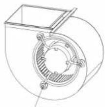
Technical line drawing of a mechanical component with a circular housing and internal structure (no text or symbols)Make sure the blower motor support is tight (3-motor mount bolts) then check to see if wheel is secured to motor shaft before operating unit.
BLOWER MOTOR SHIPPING BOLT

WARNING
The first 36 inches of supply air plenum and ductwork must be constructed of sheet metal as required by NFPA 90B. The supply air plenum or duct must have a solid sheet metal bottom directly under the unit with no openings, registers or flexible air ducts located in it. If flexible supply air ducts are used they may be located only in the vertical walls of rectangular plenum, a minimum of 6 inches from the solid bottom. Metal plenum of duct may be connected to the combustible floor base, if not, it must be connected to the unit supply duct exposed to the supply air opening from the downflow unit. Exposing combustible (non-metal) material to the supply opening of a down-flow unit can cause a fire resulting in property damage, personal injury or death.
Exception warning to downflow: Installations on concrete floor slab with supply air plenum and ductwork completely encased must be not less than 2 inches of concrete (See NFPA 90A).
2.0 GENERAL
The unit can be positioned for bottom return air in the upflow position, left and right return in the horizontal position, top return in downflow position.
This Air Handler provides the flexibility for installation in any upflow or downflow horizontal application. The direct drive motors provides a selection of air volume to match any application. 3-Speed motors provide selections of air flow to meet desired applications.
Top and side power and control wiring, accessible screw terminals for control wiring all combine to make the installation easy, and minimize installation cost. Please contact your local distributor. See Fig.1.
The appliance is only intended to supply conditioned air to one room.
2.1 UNIT DIMENSIONS
NOTE: 25" CLEARANCE IS REQUIRED IN THE FRONT OF THE UNIT FOR FILTER AND COIL MAINTENANCE.
ELECTRICAL CONNECTIOS MAY EXIT TOP OR EITHER SIDE
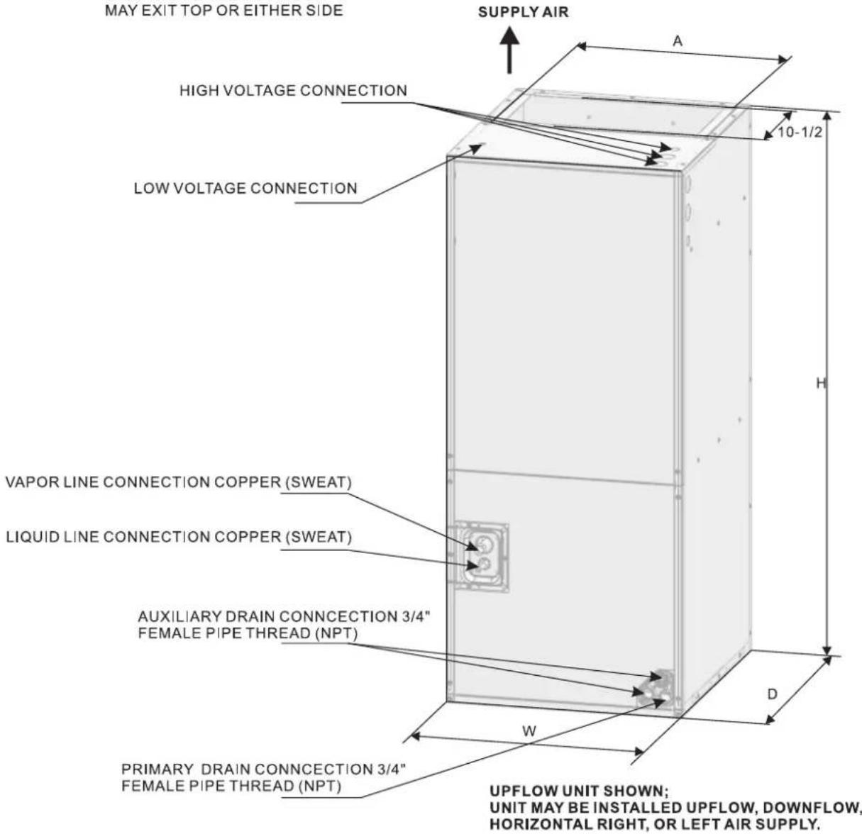
Fig.1 DIMENSIONS
DIMENSIONAL DATA
| MODEL SIZE | Dimensions inch[mm] | ||||
| UNIT HEIGHT "H" IN. [mm] | UNIT WIDTH "W" IN.[mm] | UNIT LENGTH "D" IN. [mm] | SUPPLYDUCT "A" IN[mm] | LIQUID LINE/ VAPOR LINE IN | |
| 18K | 45-3/4"[1162] | 19-5/8"[500] | 22"[560] | 17-7/8"[454] | 3/8" / 3/4" |
| 24K | 45-3/4"[1162] | 19-5/8"[500] | 22"[560] | 17-7/8"[454] | 3/8" / 3/4" |
| 30K | 45-3/4"[1162] | 19-5/8"[500] | 22"[560] | 17-7/8"[454] | 3/8" / 3/4" |
| 36K | 45-3/4"[1162] | 19-5/8"[500] | 22"[560] | 17-7/8"[454] | 3/8" / 3/4" |
| 42K | 45-3/4"[1162] | 19-5/8"[500] | 22"[560] | 17-7/8"[454] | 3/8" / 3/4" |
| 48K | 53-1/8"[1350] | 22"[560] | 24-1/2"[623] | 19-1/2"[496] | 3/8" / 7/8" |
| 60K | 53-1/8"[1350] | 22"[560] | 24-1/2"[623] | 19-1/2"[496] | 3/8" / 7/8" |
3.0 APPLICATIONS
VERTICAL UPFLOW
1) Vertical Upflow configuration is the factory set on all models (see Fig 1)
2) If a side return air opening is required, field fabricate a return air plenum with an opening large enough to supply unit and strong enough to support unit weight.
3) If return air is to be ducted, install duct flush with floor. Use fireproof resilient gasket 1/8 to 1/4 in. thick between the ducts, unit and floor. Set unit on floor over opening.
IMPORTANT NOTE
Torque applied to drain connections should not exceed 15.ft.Ibs. (see Fig.1&2)
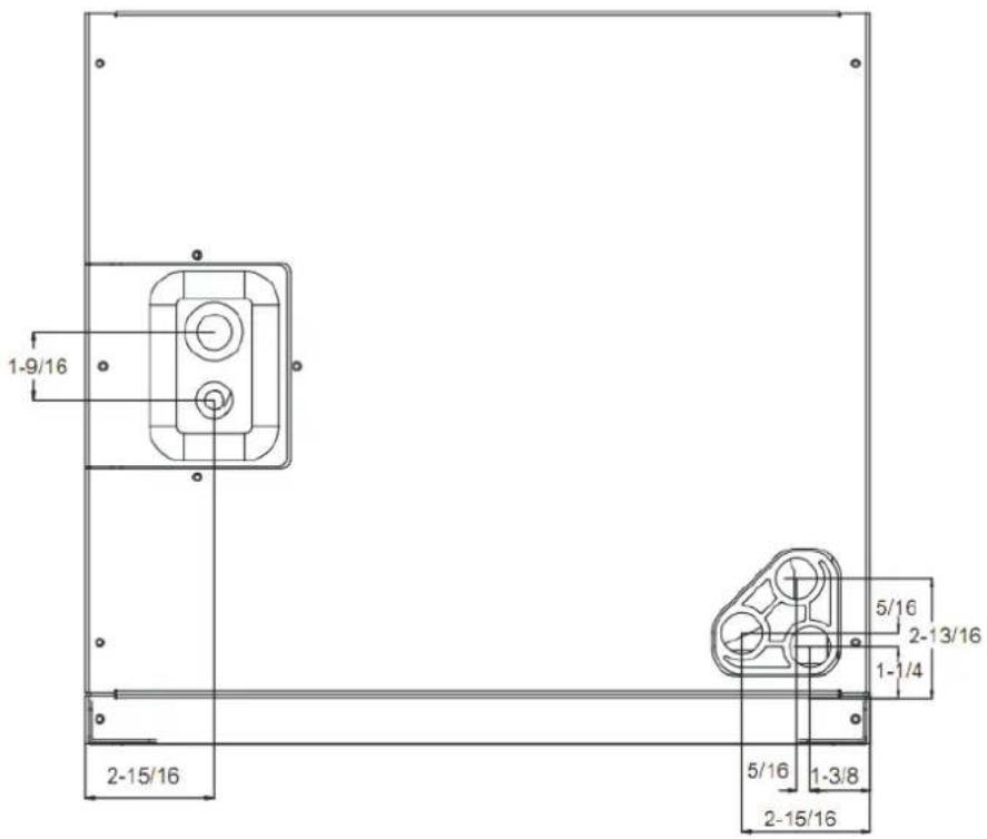
Fig.2 DIMENSIONS FOR FRONT CONNECT COIL
4.0 ELECTRICAL WIRING
Field wiring must comply with the National Electric Code and any applicable local ordinance.

WARNING
Disconnect all power to unit before installing or servicing. More than one disconnect switch may be required to de-energize the equipment. Hazardous voltage can cause severe personal injury or death.
4.1 POWER WIRING
It is important that proper electrical power is available for connection to the unit model being installed. See the unit nameplate, wiring diagram and electrical data in the installation instructions.
- If required, install a branch circuit disconnect of adequate size, located within sight of, and readily accessible to the unit.
- IMPORTANT: After the Electric Heater is installed, units may be equipped with one, two, or three 30/60 amp. circuit breakers. These breaker(s) protect the internal wiring in the event of a short circuit and serve as a disconnect. Circuit breakers installed within the unit do not provide over-current protection of the supply wiring and therefore may be sized larger than the branch circuit protection.
● Supply circuit power wiring must be 75°C minimum copper conductors only. See Electrical Data In this section for ampacity, wire size and circuit protector requirement. Supply circuit protective devices may be either fuses or "HACR" type circuit breakers.
● Power wiring may be connected to either the right, left side or top. concentric knockouts are provided for connection of power wiring to unit.
● Power wiring is connected to the power terminal block in unit electric cabinet.
4.2 CONTROL WIRING
IMPORTANT: Class 2 low voltage control wiring should not be run in conduit with main power wiring and must be separated from power wiring, unless class 1 wire of proper voltage rating is used.
● Low voltage control wiring should be 18 Awg. color-coded. For lengths longer than 100 ft., 16 Awg. wire should be used.
● See wiring diagrams attached to indoor and outdoor sections to be connected.
● Make sure, after installation, separation of control wiring and power wiring has been maintained.
4.3 GROUNDING
!
WARNING
The unit must be permanently grounded. Failure to do so can result in electrical shock causing personal injury or death.
● Grounding may be accomplished by grounding metal conduit when installed in accordance with electrical codes to the unit cabinet.
● Grounding may also be accomplished by attaching ground wire(s) to ground lug(s) provided in the unit wiring compartment.
● Ground lug(s) are located close to wire entrance on left side of unit (up-flow). Lug(s) may be moved to marked locations near wire entrance on right side of unit (upflow). If alternate location is more convenient.
- Use of multiple supply circuits require grounding of each circuit to lug(s) provided in unit.
4.4 ELECTRICAL DATA
| MODEL | VOLTAGE | HERTS | HP | RPM | SPEEDS | CIRCUIT AMPS. | MAXIMUM CIRCUIT PROTECTOR |
| 18K | 208/230 | 60 | 1/7 | 470 | 3 | 0.73 | 5(A) |
| 24K | 208/230 | 60 | 1/6 | 530 | 3 | 0.8 | 5(A) |
| 30K | 208/230 | 60 | 1/4 | 640 | 3 | 1.21 | 5(A) |
| 36K | 208/230 | 60 | 2/7 | 730 | 3 | 1.53 | 5(A) |
| 42K | 208/230 | 60 | 3/8 | 840 | 3 | 1.95 | 5(A) |
| 48K | 208/230 | 60 | 2/5 | 820 | 3 | 1.92 | 5(A) |
| 60K | 208/230 | 60 | 2/5 | 920 | 3 | 2.55 | 15(A) |
Applicable to 13-14SEER
| MODEL | VOLTAGE | HERTS | HP | SPEEDS | CIRCUIT AMPS. | MAXIMUM CIRCUIT PROTECTOR |
| 24K | 208/230 | 60 | 1/3 | 3 | 1.1 | 5(A) |
| 36K | 208/230 | 60 | 1/2 | 3 | 1.3 | 5(A) |
| 48K | 208/230 | 60 | 3/4 | 3 | 3.5 | 5(A) |
| 60K | 208/230 | 60 | 3/4 | 3 | 4.3 | 15(A) |
Applicable to 18SEER
The air distribution system has the greatest effect on airflow. The duct system is totally controlled by the contractor. For this reason, the contractor should use only industry-recognized procedures.
Heat pump systems require a specified airflow. Each ton of cooling requires between 350 and 450 cubic feet of air per minute (CFM), or 400 CFM nominally.
Duct design and construction should be carefully done. System performance can be lowered dramatically through bad planning or workmanship.
Air supply diffusers must be selected and located carefully. They must be sized and positoined to deliver treated air along the perimeter of the space. If they are too small for their intended airflow, they become noisy. If they are not located properly, they cause drafts. Reture air grilles must be properly sized to carry air back to the blower. If they are too small, they also cause noise.
The installers should balance the air distribution system to ensure proper quiet airflow to all rooms in the home. This ensures a comfortable living space.
An air velocity meter or airflow hood can give a reading of system CFM.
5.0 REFRIGERANT CONNECTIONS
Keep the coil connections sealed until refrigerant connections are made. See the Installation Instructions for the outdoor unit for details on line sizing, tubing installation, and charging information.
Coil is shipped with "No charge". Evacuate the system before charging with refrigerant.
Install refrigerant tubing so that it does not block service access to the front of the unit.
Nitrogen should flow through the refrigerant lines while brazing.
Use a brazing shield to protect the cabinet's paint and a wet rag to protect the rubber grommet from being damaged by torch flames. After the refrigerant connections are made, seal the gap around the connections with pressure sensitive gasket.
5.1 CONDENSATE DRAIN TUBING
Consult local codes for specific requirements.
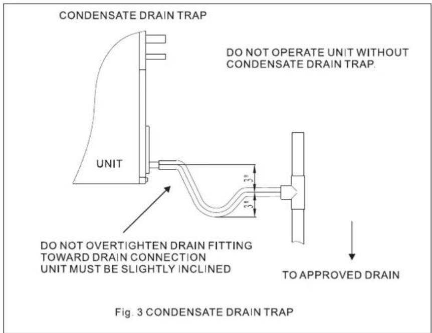
IMPORTANT:
- When making drain fitting connections to the drain pan, use a thin layer of Teflon paste, silicone or Teflon tape and install, hand tighten.
- When making drain fitting connections to drain pan, do not overtighten. Over tightening fittings can split pipe connetions on the drain pan.
● Install drain lines so they do not block service access to front of the unit. Minimum clearance of 24 inches is required for filter, coil or blower removal and service access.
● Make sure unit is level or pitched slightly toward primary drain connection so that water will drain completely from the pan. (See Fig. 3)
- Do not reduce drain line size less than connection size provided on condensate drain pan.
- All drain lines must be pitched downward away from the unit a minimum of 1/8"per foot of line to ensure proper drainage.
- Do not connect condensate drain line to a closed or open sewer pipe. Run condensate to an open drain or run line to a safe outdoor area.
● The drain line should be insulated where necessary to prevent sweating and damage due to condensate forming on the outside surface of the line.
● Make provisions for disconnecting and cleaning of the primary drain line should it become necessary. Install a 3 inch trap in the primary drain line as close to the unit as possible. Make sure that the top of the trap is below connection to the drain pan to allow complete drainage of pan (See Fig. 3).
● Auxiliary drain line should be run to a place where it will be noticeable if it becomes operational. Homeowner should be warned that a problem exists if water should begin running from the auxiliary drain line.
● Plug the unused drain connection with the plugs provided in the parts bag, using a thin layer of teflon paste, silicone or teflon tape to form a water tight seal.
● Test condensate drain pan and drain line after installation is complete. Pour water into drain pan, enough to fill drain trap and line. Check to make sure drain pan is draining completely, no leaks are found in drain line fittings, and water is draining from the termination of the primary drain line.
6.0 AIR FILTER (not factory-installed)
● External filter or other means of filtration is required. Units should be sized for a maximum of 300 feet/min. air velocity or what is recommended for the type filter installed.
Filter application and placement are critical to airflow, which may affect the heating and cooling system performance. Reduced airflow can shorten the life of the system's major components, such as motor, limits, elements, heat relays, evaporator coil or compressor. Consequently, we recommend that the return air duct system have only one filter location. For systems with a return air filter grill or multiple filter grills, can have a filter installed at each of the return air openings.
If adding high efficiency filters or electronic air filtration systems, it is very important that the air flow is not reduced. If air flow is reduced the overall performance and efficiency of the unit will be reduced. It is strongly recommended that a professional installation technician is contacted to ensure installation of these such filtration systems are installed correctly.
IMPORTANT: DO NOT DOUBLE FILTER THE RETURN AIR DUCT SYSTEM. DO NOT FILTER THE SUPPLY AIR DUCT SYSTEM. THIS WILL CHANGE THE PERFORMANCE OF THE UNIT AND REDUCE AIRFLOW.

WARNING
Do not operate the system without filters. A portion of the dust entrained in the air may temporarily lodge In the duct runs and at the supply registers. Any circulated dust particles could be heated and charred by contact with the air handler elements. This residue could soil ceilings, walls, drapes, carpets and other articles in the house. Soot damage may occur with filters in place, when certain types of candles, oil lamps or standing pilots are burned.
7.0 FILTER INSTALLATION DIMENSIONS
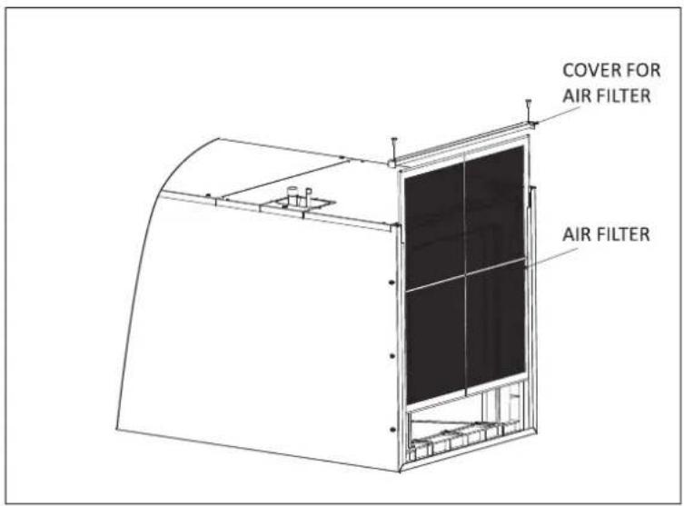
Fig. 4 EXTERNAL FILTER BASE
DIMENSIONAL DATA
| MODEL | FILTER SIZE IN[mm] |
| 18/24/30/36/42 | 18.1×21.4[460×544] |
| 48/60 | 20.5×23.8[521×605] |
NOTE: The thickness of the filter should within 1"[25mm].
AIR FILTER REMOVAL
- Tear down the two bolts signed A and B, take down the cover for air filter, see in Figure 4.
- Hold the edge of the air filter and extract out.
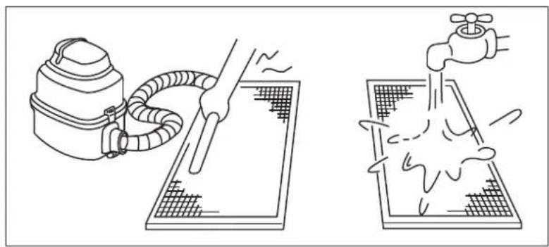
- Clean the air filter (Vacuum cleaner or pure water may be used to clean the air filter. If the dust accumulation is too heavy, use soft brush and mild detergent to clean it and dry out in cool place).
natural_image
Illustration of two different methods: a vacuum cleaner and a faucet, both performing a cleaning or cleaning process (no text or symbols present)8.0 WIRING DIAGRAM
- To avoid the electrical shock, please connect the air conditioner with the ground lug. The main power plug in the air conditioner has been joined with the ground wiring, please don't change it freely.
- The power socket is used as the air conditioner specially.
- Don't pull the power wiring hard.
- When connecting the air conditioner with the ground, observe the local codes.
- If necessary, use the power fuse or the circuit, breaker or the corresponding scale ampere.
flowchart
graph TD
    subgraph THERMOSTAT
        W2["W2"] --> A["INDOOR UNIT"]
        B["B"] --> A
        C["C"] --> A
        R["R"] --> A
        Y["Y"] --> A
        G["G"] --> A
    end

    subgraph OUTDOOR UNIT
        G["G"] --> A
        R["R"] --> A
        C["C"] --> A
        w1["w1"] --> A
        w2["w2"] --> A
        Black["BLACK"] --> A
        White["WHITE"] --> A
        Black/White["BLACK/WHITE"] --> A
    end

    A --> B
    A --> C
    A --> Y
    A --> G
    style THERMOSTAT fill:#f9f,stroke:#333
    style OUTDOOR UNIT fill:#bbf,stroke:#333
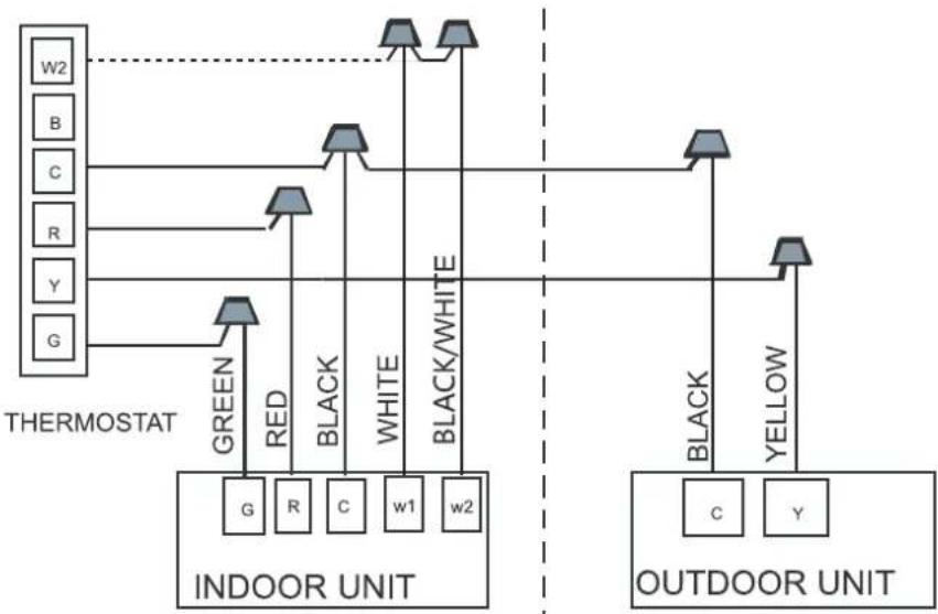
Wiring connection for A/C Systems.
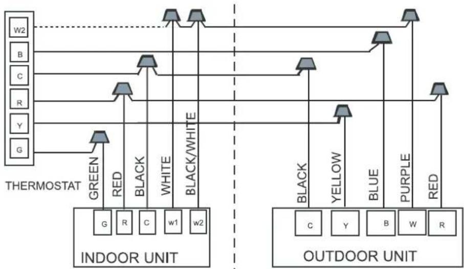
flowchart
graph TD
    subgraph THERMOSTAT
        A["Green"] --> B["INDOOR UNIT"]
        C["RED"] --> B
        D["BLACK"] --> B
        E["WHITE"] --> B
        F["Black/WHITE"] --> B
        G["W1"] --> B
        H["W2"] --> B
    end

    subgraph OUTDOOR UNIT
        I["BLACK"] --> J["INDOOR UNIT"]
        K["YELLOW"] --> J
        L["BLUE"] --> J
        M["PURPLE"] --> J
        N["W"] --> J
        O["R"] --> J
    end

    style THERMOSTAT fill:#f9f,stroke:#333
    style OUTDOOR UNIT fill:#bbf,stroke:#333
Wiring connection for 14EER H/P Systems.
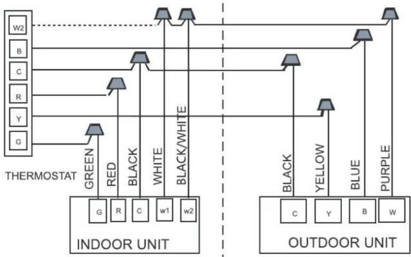
flowchart
graph TD
    subgraph THERMOSTAT
        W2["W2"] --> IND["INDOOR UNIT"]
        B["B"] --> IND
        C["C"] --> IND
        R["R"] --> IND
        Y["Y"] --> IND
        G["G"] --> IND
        GREEN["GREEN"] --> IND
        RED["RED"] --> IND
        BLACK["BLACK"] --> IND
        WHITE["WHITE"] --> IND
        BLACK/WHITE["BLACK/WHITE"] --> IND
    end

    subgraph OUTDOOR UNIT
        G["G"] --> IND
        R["R"] --> IND
        C["C"] --> IND
        w1["w1"] --> IND
        w2["w2"] --> IND
        BLACK["BLACK"] --> OUTDOORUNIT
        YELLOW["Y"] --> OUTDOORUNIT
        BLUE["B"] --> OUTDOORUNIT
        Purple["W"] --> OUTDOORUNIT
    end

    IND --> OUTDOORUNIT
    OUTDOORUNIT --> OUTDOORUNIT
Wiring connection for 18EER H/P Systems.
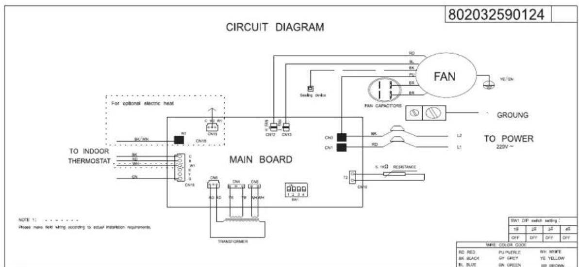
Applicable to 18k, 24k, 30k, 36k, 42k of 13-14SEER
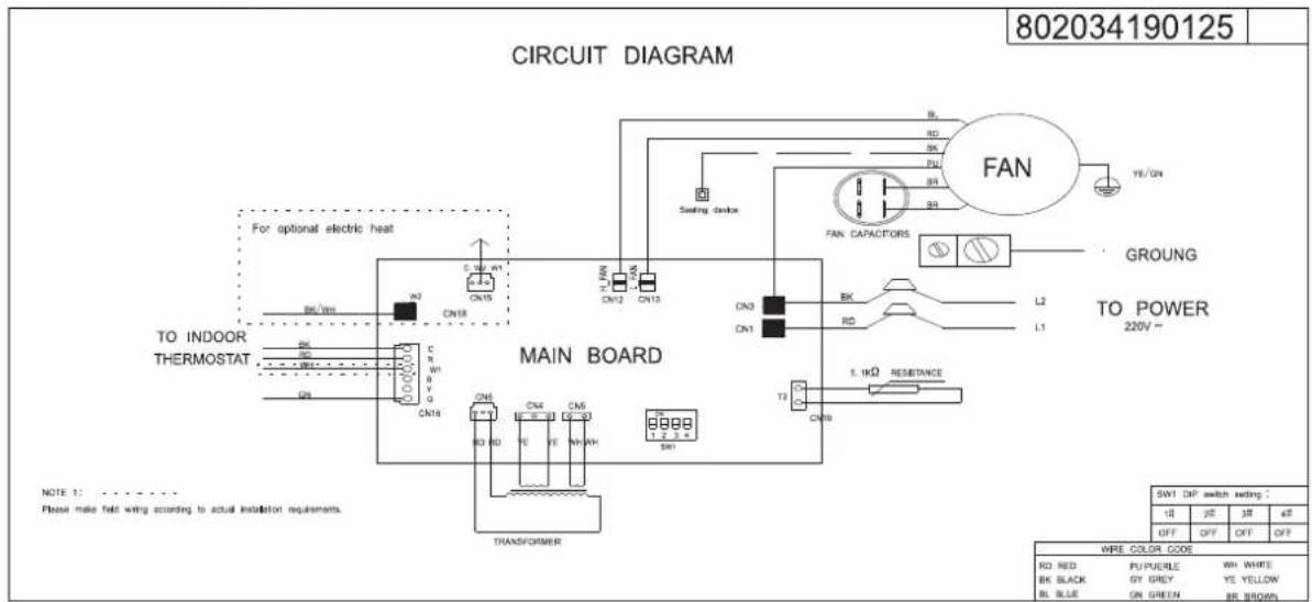
Applicable to 48K of 13-14SEER
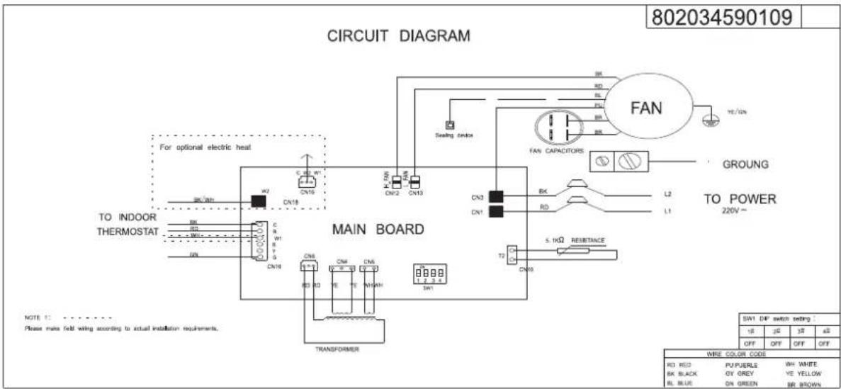
Applicable to 60K of 13-14SEER
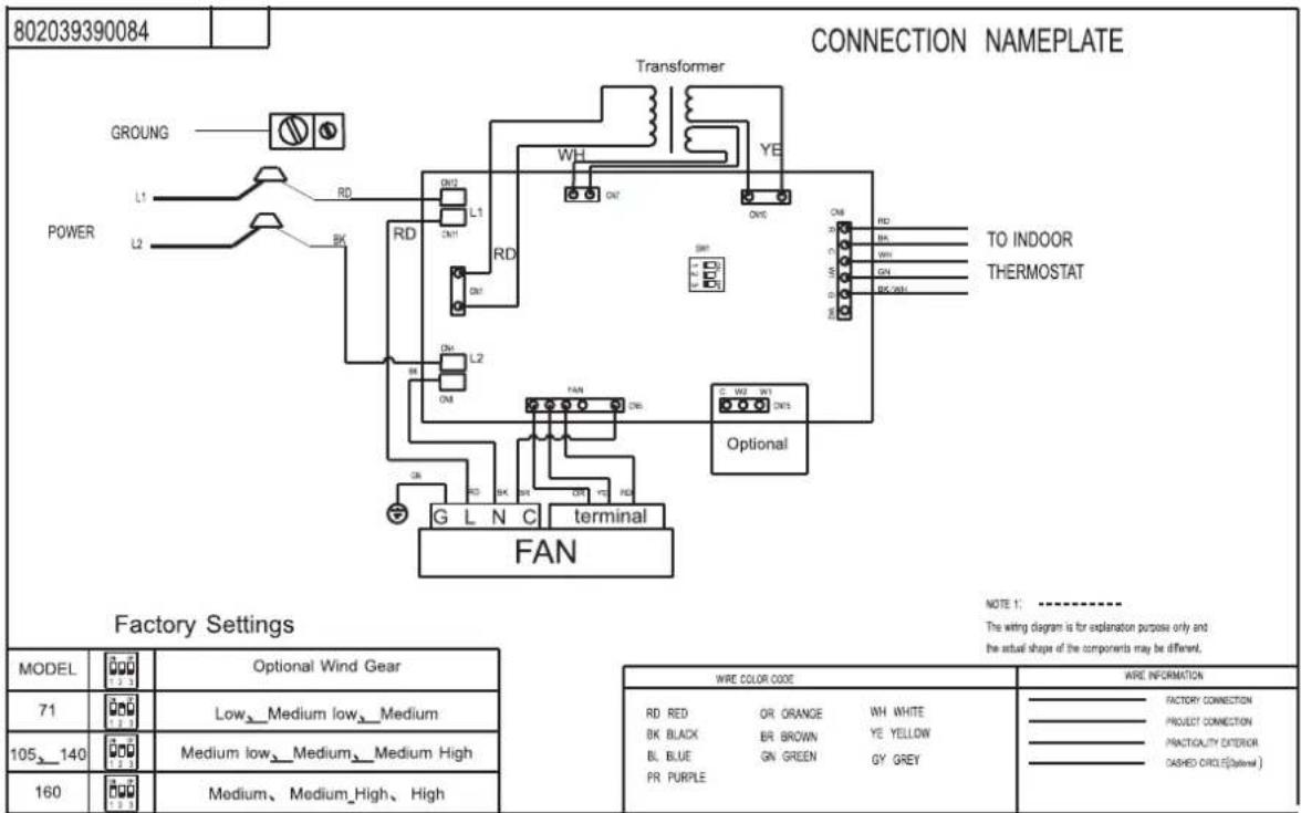
Applicable to 24k, 36k, 48k, 60k of 18SEER
9.0 ELECTRIC WIRING GAUGE
Note:
The cross-section areas of wires or lines should not be less than the corresponding ones listed in the table below; Besides, if the power wires is quite long from the unit, please choose the windings with larger cross-section area to guarantee the normal power supply.
| Model (cooling only type) | 18K | 24K | 30K | 36K | 42K | 48K | 60K | ||
| Line Gauge | Indoor Unit Power Line | Line Quantity | 3 | 3 | 3 | 3 | 3 | 3 | 3 |
| Line Diameter(AWG) | 16 | 16 | 16 | 16 | 16 | 16 | 16 | ||
| Outdoor Unit Power Line | Line Quantity | 3 | 3 | 3 | 3 | 3 | 3 | 3 | |
| Line Diameter(AWG) | 14 | 14 | 12 | 12 | 10 | 10 | 10 | ||
| Outdoor-Indoor Singal Line | Line Quantity | 2 | 2 | 2 | 2 | 2 | 2 | 2 | |
| Line Diameter(AWG) | 18 | 18 | 18 | 18 | 18 | 18 | 18 | ||
| Thermostat Singal Line | Line Quantity | 4 | 4 | 4 | 4 | 4 | 4 | 4 | |
| Line Diameter(AWG) | 18 | 18 | 18 | 18 | 18 | 18 | 18 | ||
| Model (cooling & heating type) | 18K | 24K | 30K | 36K | 42K | 48K | 60K | ||
| Line Gauge | Indoor Unit Power Line | Line Quantity | 3 | 3 | 3 | 3 | 3 | 3 | 3 |
| Line Diameter(AWG) | 16 | 16 | 16 | 16 | 16 | 16 | 16 | ||
| Outdoor Unit Power Line | Line Quantity | 3 | 3 | 3 | 3 | 3 | 3 | 3 | |
| Line Diameter(AWG) | 14 | 14 | 12 | 12 | 10 | 10 | 10 | ||
| Outdoor-Indoor Singal Line | Line Quantity | 2 | 2 | 2 | 2 | 2 | 2 | 2 | |
| Line Diameter(AWG) | 18 | 18 | 18 | 18 | 18 | 18 | 18 | ||
| Thermostat Singal Line | Line Quantity | 6 | 6 | 6 | 6 | 6 | 6 | 6 | |
| Line Diameter(AWG) | 18 | 18 | 18 | 18 | 18 | 18 | 18 | ||

natural_image
Abstract grayscale gradient background with radial lines, no text or symbols present- INSTALLATION and OWNER'S MANUAL FOR
- RECOGNIZE THIS SYMBOL AS AN INDICATION OF IMPORTANT SAFETY INFORMATION
- WARNING
- INSTALLATION and OWNER'S MANUAL
- INDOOR SPLIT-SYSTEM UNIT
- MODELS:UP TO 18 SEER
- TO 5 TONS
- CONTENTS
- SAFETY
- GENERAL
- UNIT DIMENSIONS
- APPLICATIONS
- VERTICAL UPFLOW
- IMPORTANT NOTE
- ELECTRICAL WIRING
- POWER WIRING
- CONTROL WIRING
- GROUNDING
- !
- ELECTRICAL DATA
- REFRIGERANT CONNECTIONS
- CONDENSATE DRAIN TUBING
- IMPORTANT:
- AIR FILTER (not factory-installed)
- FILTER INSTALLATION DIMENSIONS
- AIR FILTER REMOVAL
- WIRING DIAGRAM
- ELECTRIC WIRING GAUGE
- Note:
Brand : Daizuki
Model : AHC60H18
Category : Air conditioner