HYB-1000 - Toilets Sloan - Free user manual and instructions
Find the device manual for free HYB-1000 Sloan in PDF.


| Product Type | Commercial Flushometer Toilet |
| Brand | Sloan |
| Model | HYB-1000 |
| Flushing System | Dual-Flush with Sensor Operation |
| Water Consumption | 1.0 or 1.6 GPF (selectable) |
| Bowl Shape | Elongated |
| Rough-In | 12 inches (standard) |
| Dimensions (L x W x H) | 28.5 x 20.5 x 30 inches |
| Weight | 80 lbs |
| Power Supply | 4 AA batteries (6V DC) |
| Battery Life | Up to 300,000 flushes |
| Sensor Range | Programmable, 20-30 inches |
| Material | Vitreous China with Sleek Design |
| Seat Included | Yes, with Soft-Close Mechanism |
| Flush Valve | Piston-operated, Dual Flush |
| Installation | Floor-mount, Standard Rough-In |
| Warranty | 10 years (limited) |
| Maintenance | Clean with mild soap; avoid abrasive cleaners |
| Spare Parts | Replacement piston kit, sensor lens, battery pack |
| Safety | Meets ANSI/ASME A112.19.2 standards |
Frequently Asked Questions - HYB-1000 Sloan
User questions about HYB-1000 Sloan
0 question about this device. Answer the ones you know or ask your own.
Ask a new question about this device
Download the instructions for your Toilets in PDF format for free! Find your manual HYB-1000 - Sloan and take your electronic device back in hand. On this page are published all the documents necessary for the use of your device. HYB-1000 by Sloan.
USER MANUAL HYB-1000 Sloan
with Jetrinse™ Solution
Technology NEW CONSTRUCTION
INSTALLATION INSTRUCTIONS
BEFORE STARTING INSTALLATION:
IMPORTANT Do not install on copper DWV due to copper's susceptibility to corrosion.
- ADA requires a lip height of 17" or lower. To allow for variances and assure compliance Sloan recommends roughing the drain line to achieve a 16- 12 " lip height
- Check slope. Downhill slope, per code, is essential because waterfree urinals depend on gravity flow.
- Check DWV material. Suitable materials include cast iron, PVC, ABS and galvanized steel.
TUBE CUTTING CHART
- Measure drain nipple depth (inches) to find trim length (inches)
• 13 7/8" or more DO NOT CUT - 3 3/4" or less DO NOT USE TUBE
| OR LESS TRIM |
| 1334" 14" |
| 1312 12 |
| 1314 34 |
| 131 |
| 1234 14 |
| 1212 12 |
| 1214 14 |
| 122 |
| 1134 24 |
| 1112 22 |
| 1114 24 |
| 113 |
| 1034 34 |
| 1012 32 |
| OR LESS TRIN | |
| 1012" | 334" |
| 10 | 4 |
| 912 | 414 |
| 912 4 | 1/2 |
| 914 4 | 3/4 |
| 9 | 5 |
| 812 | 514 |
| 812 5 | 1/2 |
| 814 5 | 3/4 |
| 8 | 6 |
| 734 6 | 1/4 |
| 712 6 | 1/2 |
| 714 6 | 3/4 |
| 77 | |
| OR LESS | TRIM |
| 634" | 714" |
| 612 | 712 |
| 614 | 714 |
| 6 | 8 |
| 514 | 814 |
| 512 | 812 |
| 514 | 814 |
| 5 | 9 |
| 434 | 914 |
| 412 | 912 |
| 414 | 934 |
| 4 | 10 |
CUSTOMER CARE
1-800-982-5839
customer.service@sloanvalve.com

CAUTION After removing any urine from the drum line. It's normal for certain naturally occurring but potentially hazardous sewer gases to escape through the opening until the wireless cartridge is installed properly into the waterless urine. If you should have a clean, so much as
need to leave an open drain line unbroken error removing the urnel from the well-tempered wedge vapor lowers or a reg into the drain hole to reduce any out-of-sweer gases, and remove the paper to wear or drag prior to completing the urne or cartridge installation. Never smoke, have an open flame, or place your nose or mouth near open drain lines or waterless urnal housings into which a cartridge is not yet properly installed. You also can wear a breathing mask when removing or installing any waterless urnal or cartridge to reduce patential exposure to any such gases.
Slapa.com
The information in this document is subject to change without notice. ©2018 Sloan valve Company All rights reserved.
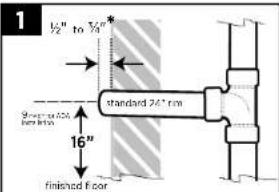
Set drain line height 16" from finished floor (standard 24" rim) or 9" Max. for ADA installation. Threaded nipple should extend 1/2 to 3/4" from wall * IMPORTANT Nipple must not extend more than 3/4" past the finished wall
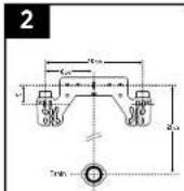
Carrier stud placement if using in-wall carrier set bearing as shown above.
natural_image
Illustration of a mechanical tool interacting with a threaded component (no text or symbols)C
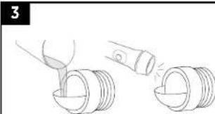
A. Clean Face of drain nipple
B. Install the clear inspection disc with the compression nut
C. Slowly pour water into the drain.
D. Use a flashlight to check the pitch/slope no water should be present in the inspection disc or nipple.
E. Remove disc and nut after inspection.
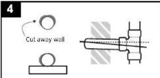
Lift drain line & brace with mending plate
Adjust drain to achieve pitch only if standing water is present (code requires 1/4" drop per foot of drain line for proper pitch). Seal wall according to code.
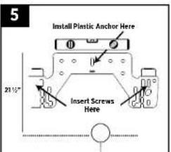
Measure and mark rough in. If in-wall carrier is not used. Use a 5/16" masonry bit to drill hole, then install the hanger bracket with one plastic anchor and screw.
Install 1/2" x 3/8" compression straight stop with the handle facing floor.
A
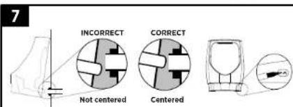
A. Hang bowl on the bracket and check tail pipe alignment, then remove the bowl and adjust the bracket as needed. Re-hang and re-check bowl alignment with the drain line. Tail pipe should align with center of drain line. B. Mark anchor holes then remove bowl without moving hanger bracket.
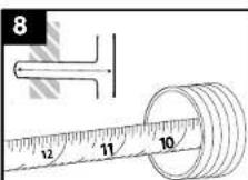
Determine the drain nipple length by measuring the distance between the back of the sanitary tee (or elbow) to the front edge of the nipple
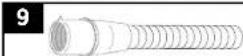
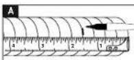
A. Find the drain nipple depth on the Tube Cutting Chart (left). Measure and mark the specified trim length on the insert tube at the nearest 1/4" groove.
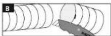
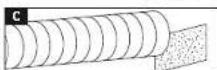
B. Cut the tube at the groove using a sharp utility knife to ensure a square, flat cut. C. Clean burrs from the cut end by using emery paper.
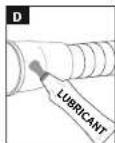
D. Apply lubricant to the outside of the rubber bushing and ribbed inside area. E. Insert tube and bushing. IMPORTANT Be sure arrow tab is at the 12:00 position.
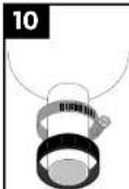
Apply lubricant to tailpipe of housing. Place hose clamp and compression nut onto the housing tailpipe.
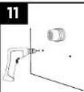
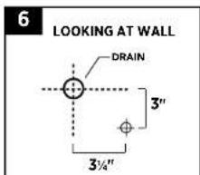
Drill holes with 3/16" masonry bit for the lower anchor screws and insert plastic anchors.
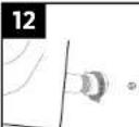
Hang the bowl inserting tailpipe into bushing, and tighten coupling and base clamp. Install anchor screws with washers.
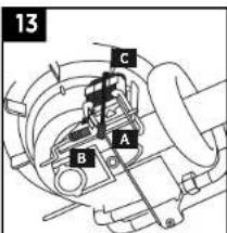
Connect battery A to wire B. Wait 1 minute for system to start up. Note system will allow 2 manual fushing before causing 30 seconds.
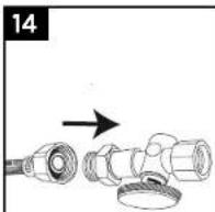
Put adaptor onto stop then attach supply line to adapter. Turn water on and assure there are no connection leaks.
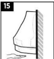
Wave hand under IR switch to activate test rinse and ensure there is no standing water in housing. System will operate automatically every 48 hours from battery plug in
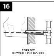
If standing water exists, there is clogged or there is improper slopes installed in housing. See step 4 correct and reinstall urine
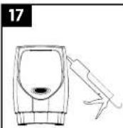
Caulk the bowl to the wall if there is good flow and no leaks or standing water in housing.
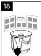
Install cartridge as per the cartridge instruction sheet.
Brand : Sloan
Model : HYB-1000
Category : Toilets