
RB1270X4A - Battery CyberPower - Free user manual and instructions
Find the device manual for free RB1270X4A CyberPower in PDF.


| Product Type | Sealed Lead-Acid Battery (VRLA) |
| Model | RB1270X4A |
| Nominal Voltage | 12V |
| Capacity (20hr rate) | 7.2Ah |
| Dimensions (L x W x H) | 5.94 x 2.56 x 3.70 inches (151 x 65 x 94 mm) |
| Weight | 4.85 lbs (2.2 kg) |
| Terminal Type | F1 (0.187 inch) and F2 (0.250 inch) compatible |
| Chemistry | Lead-Acid, Absorbent Glass Mat (AGM) |
| Maintenance | Valve-regulated, maintenance-free |
| Operating Temperature | Charge: 32°F to 104°F (0°C to 40°C); Discharge: -4°F to 122°F (-20°C to 50°C) |
| Storage Temperature | 32°F to 86°F (0°C to 30°C) |
| Max Charging Current | 2.16A (0.3C) |
| Float Charging Voltage | 13.5V to 13.8V at 77°F (25°C) |
| Cycle Charging Voltage | 14.4V to 15.0V at 77°F (25°C) |
| Safety Features | Overcharge protection, flame-retardant casing |
| Spare Parts & Repairability | Battery is sealed and non-repairable; replace entire unit |
| Compliance | UL, CE, RoHS certified |
| Typical Application | UPS (Uninterruptible Power Supply) backup, emergency lighting, alarm systems |
| Expected Lifespan | 3-5 years typical (depends on usage and environment) |
| Disposal | Recycle at designated lead-acid battery recycling center |
Frequently Asked Questions - RB1270X4A CyberPower
User questions about RB1270X4A CyberPower
0 question about this device. Answer the ones you know or ask your own.
Ask a new question about this device
Download the instructions for your Battery in PDF format for free! Find your manual RB1270X4A - CyberPower and take your electronic device back in hand. On this page are published all the documents necessary for the use of your device. RB1270X4A by CyberPower.
USER MANUAL RB1270X4A CyberPower
Intelligent LCD Series, AVR Series
MODEL: CP600LCD, CP825LCD, CP800AVR, CP685AVR-G, CP825AVR-G, CP685AVRLCD-G, CP825AVRLCD-G, AVRG750U, AVRG900U, AVRG750LCD, AVRG900LCD
natural_image
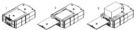
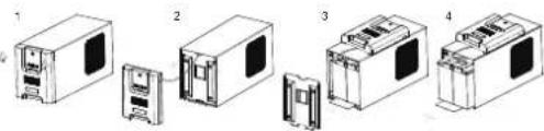
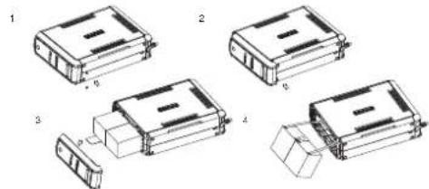
Three technical line drawings of a mechanical assembly or housing component, showing front, side, and top views with no visible text or symbols.- Place the UPS on its top and remove the retaining screw (figure 1).
- Slide the battery compartment cover completely off of the unit (figure 2).
- Remove the battery from the compartment and disconnect the battery wires from the battery. Install the replacement battery by connecting the red wire to the positive (+) terminal and the black wire to the negative (-) terminal of the battery. (figure 3)
- Slide the battery compartment cover over the battery and tighten the retaining screw.
- Charge the unit for 4–8 hours to ensure the UPS performs expected runtimes.
MODEL: CP850AVRLCD, CP1000AVRLCD
natural_image
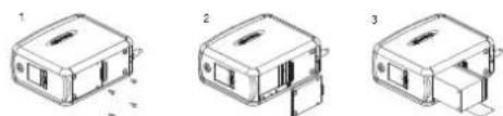
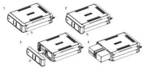
Three technical line drawings of a 3D mechanical component with no visible text or symbols- Place the UPS on its side and locate the battery compartment cover on the bottom of the UPS. Remove the four (4) retaining screws and pull the battery compartment cover off the UPS (figure 1 & 2).
- Remove the battery from the compartment and disconnect the battery wires from the batteries. Install the replacement batteries by connecting the red wire and black wire to the same color wires from the battery pack. Put the battery pack into the compartment (figure 3).
- Slide the battery compartment cover over the battery and tighten the retaining screw. Charge the unit for 4 - 8 hours to ensure the UPS performs expected runtimes.
1
AVR Series
MODEL: CP900AVR, CP1200AVR, CP1500AVRT, CP1285AVRLCD, CP1350AVRLCD, CP1500AVRLCD
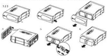
- Place the UPS on its side to locate and remove the front panel retaining screws from the bottom of the UPS.
- Slide the cover (front panel) towards the bottom of the UPS.
- Remove it from the unit.
- Disconnect the cable located at the top of the cover.
- Disconnect the battery wires from the batteries.
- Remove the batteries from the compartment.
- Install the replacement batteries by connecting the red and black wires to the same color wires from the battery pack. Put the battery pack back into the compartment.
- Replace the battery compartment cover and tighten the retaining screw. Charge the unit for 4-8 hours to ensure the UPS performs expected runtimes.
Smart APP Intelligent LCD Series
MODEL: OR500LCDRM1U, OR700LCDRM1U, OR1000LCDRM1U, OR1500LCDRM1U
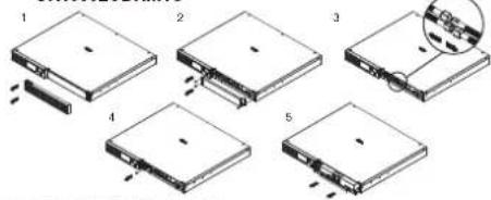
- Remove the right side front panel.
- Remove the three retaining screws for the cable protection cover and remove the cover.
- Disconnect the black and red cable.
- Remove the one retaining screw holding the battery pack in place.
- Remove the battery pack.
- Install the new battery pack. Assemble the screws, cover, cable and front panel in the reverse order of the previous steps. Charge the unit for 4-8 hours to ensure the UPS performs expected runtimes.
●
MODEL: OR1500LCDRM2U, OR2200LCDRM2U, OR1500LCDRTXL2U, OR2200LCDRTXL2U
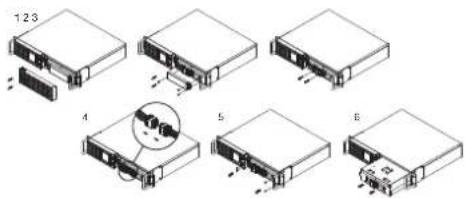
- Remove the right side front panel.
- Remove the three retaining screws for the cable protection cover and remove the cover.
- Remove the two retaining screws from the cable connectors.
- Disconnect the black and red cable.
- Remove the four retaining screws holding the battery pack in place.
- Remove the battery pack.
- Install the new battery pack. Assemble the screws, cover, cable and front panel in the reverse order of the previous steps. Charge the unit for 4-8 hours to ensure the UPS performs expected runtimes.
MODEL: CPS1500AVR
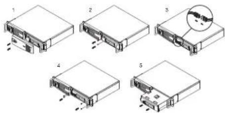
- Remove the right side front panel.
- Remove the two retaining screws for the cable protection cover and remove the cover.
- Disconnect the black and red cable.
- Remove the four retaining screws holding the battery pack in place.
- Remove the battery pack.
- Install the new battery pack. Assemble the screws, cover, cable and front panel in the reverse order of the previous steps. Charge the unit for 4-8 hours to ensure the UPS performs expected runtimes.
●
Smart APP SINEWAVE Series
MODEL: PR750LCD
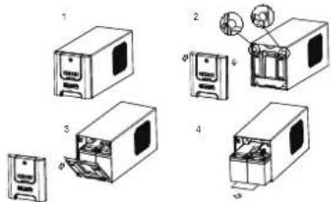
- Remove the front panel of the UPS.
- Pull out both round knobs and remove the battery compartment cover completely off of the unit.
- Remove the batteries from the compartment.
- Disconnect the battery wires from the batteries.
- Install the replacement batteries by connecting the wire bundle (composed of one red wire and one black wire) to the connector from the battery pack. Put the batteries back into the compartment.
- Re-install the battery compartment cover and push both round knobs back into place. Put the front panel back on the UPS.
- Connect to AC power and charge the new batteries for up to 16 hours to insure a full charge.
MODEL: PR1000LCD
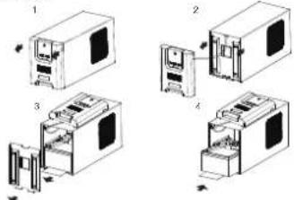
- Remove the front panel of the UPS.
- Remove two screws from the battery compartment cover and slide the cover completely off of the unit.
- Remove the batteries from the compartment. Disconnect the battery wires from the batteries.
- Install the replacement batteries by connecting the wire bundle (composed of one red wire and one black wire) to the connector from the battery pack.
- Put the batteries back into the compartment. Re-install the battery compartment cover and tighten the retaining screws. Put the front panel back on the UPS.
- Connect to AC power and charge the new batteries for up to 16 hours to insure a full charge.
4
MODEL: PR1500LCD
natural_image
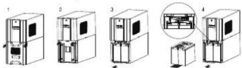
Exploded view diagram of four electronic devices with internal components (no text or labels)- Remove the front panel of the UPS.
- Remove two screws from the battery compartment cover and slide the cover completely off of the unit.
- Remove the batteries from the compartment. Disconnect the battery wires from the batteries.
- Install the replacement batteries by connecting the wire bundle (composed of one red wire and one black wire) to the connector from the battery pack.
- Put the batteries back into the compartment. Re-install the battery compartment cover and tighten the retaining screws. Put the front panel back on the UPS.
- Connect to AC power and charge the new batteries for up to 16 hours to insure a full charge.
MODEL: PR2200LCD, PR3000LCD
- Remove the front panel of the UPS and two screws from the battery compartment cover and slide the cover completely off of the unit.
- Pull out the battery pack on the outside from the compartment. Disconnect the battery connector from the batteries.
- Before removing the battery pack on the inside, unlock the cable tie and pull out the battery wires. Disconnect the battery connector from the batteries.
- Install the replacement battery pack on the inside by connecting the wire bundle connector (composed of one red wire and one black wire) to the connector from the battery pack. Lock the battery wires back with the cable tie.
- Install the replacement batteries on the outside by connecting the wire bundle connector (composed of one red wire and one black wire) to the connector from the battery pack. Put the battery pack on the outside back into the compartment.
- Re-install the battery compartment cover and tighten the retaining screws and put the front panel back on the UPS.
- Connect to AC power and charge the new batteries for up to 16 hours to insure a full charge. Note: The battery pack on the outside has a fuse, while the battery pack on the inside does not.
5
MODEL: PR750LCDRM1U, PR1000LCDRM1U
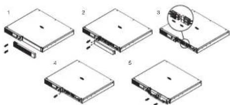
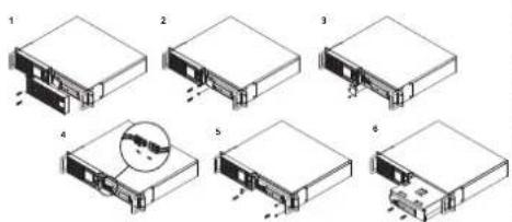
- Remove the right side front panel.
- Remove the two retaining screws for the cable protection cover and remove the cover.
- Disconnect the black and red cable.
- Remove the one retaining screw holding the battery pack in place.
- Remove the battery pack.
- Install the new battery pack. Assemble the screws, cover, cable and front panel in the reverse sequence of the above steps. Charge the unit for 4-8 hours to ensure the UPS performs expected runtimes.
MODEL: PR1500SWRM2U, PR2200SWRM2U
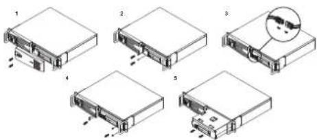
- Remove the right side front panel.
- Remove the two retaining screws for the cable protection cover and remove the cover.
- Disconnect the black and red cable.
- Remove the four retaining screws holding the battery pack in place.
- Remove the battery pack.
- Install the new battery pack. Assemble the screws, cover, cable and front panel in the reverse order of the previous steps. Charge the unit for 4-8 hours to ensure the UPS performs expected runtimes.
6
MODEL: PR1000LCDRT2U, PR1000LCDRTXL2U, PR1500LCDRT2U, PR2200LCDRT2U, PR3000SWRM2U
- Remove the right side front panel.
- Remove the three retaining screws for the cable protection cover and remove the cover.
- Remove the two retaining screws from the cable connectors.
- Disconnect the black and red cable.
- Remove the four retaining screws holding the battery pack in place.
- Remove the battery pack.
- Install the new battery pack. Assemble the screws, cover, cable and front panel in the reverse order of the previous steps. Charge the unit for 4-8 hours to ensure the UPS performs expected runtimes.
MODEL: PR1000LCDRTXL2Ua, PR1500LCDRTXL2U, PR2200LCDRTXL2U, PR3000LCDRT2U, PR3000LCDRTXL2U
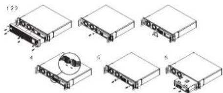
- Remove the six retaining screws, and remove the front panel from the UPS.
- Remove the two retaining screws for the cable protection cover and remove the cover.
- Remove the two retaining screws from the cable connectors.
- Disconnect the black and red cable.
- Remove the three retaining screws holding the battery pack in place.
- Remove the battery pack.
- Install the new battery pack. Assemble the screws, cover, cable and front panel in the reverse order of the previous steps. Charge the unit for 4-8 hours to ensure the UPS performs expected runtimes.

PFC SINEWAVE Series
MODEL: PR5000LCDRTXL5U, PR6000LCDRTXL5U
flowchart
graph TD
    A["Raw Material Input"] --> B["Material Release"]
    B --> C{Material Breakout}
    C -->|Yes| D["Process Unit"]
    C -->|No| E["Product Output"]
    D --> F["Final Assembly"]
    E --> F
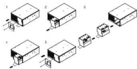
- Remove the front panel.
- Remove the two retaining screws of the cable protection cover and remove the cover.
- Pull the plastic sticker out slowly to remove the battery module.
- Put the new battery modules back into the compartment
- Tighten the screws and replace the cable protection cover and the front panel.
MODEL: CP850PFCLCD, CP1000PFCLCD
natural_image
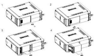
Four technical line drawings of a device housing with internal components and mounting points (no text or symbols)- Turn the UPS on its side. Remove the retaining screw located on the bottom of the UPS.
- Slide the battery compartment cover completely off of the unit.
- Remove the batteries from the compartment.
- Disconnect the battery wires from the batteries.
- Install the replacement batteries by connecting the red wire (+) and black wire (-) to the same color connectors from the battery pack. Put the batteries back into the compartment.
- Slide back the battery compartment cover and tighten the retaining screw. Recharge the UPS for 8-16 hours to fully charge the battery

MODEL: CP1350PFCLCD
- Turn the UPS on its side. Remove the front panel retaining screws located on the bottom of the UPS.
- Slide the battery compartment cover (front panel) completely off of the unit.
- Remove the batteries from the compartment.
- Disconnect the battery wires from the batteries.
- Install the replacement batteries by connecting the red wire (+) and black wire (-) to the same color connectors from the battery pack. Put the batteries back into the compartment.
- Slide back the battery compartment cover and tighten the retaining screws. Recharge the UPS for 8-16 hours to fully charge the battery.
MODEL: CP1500PFCLCD
natural_image
Technical line drawings of four different electronic component assemblies (no text or symbols)- Turn the UPS on its side. Remove the front panel retaining screws located on the bottom of the UPS.
- Slide the battery compartment cover (front panel) completely off of the unit.
- Remove the batteries from the compartment.
- Disconnect the battery wires from the batteries.
- Install the replacement batteries by connecting the wire bundle (composed of one red wire and one black wire) to the connector from the battery pack. Put the batteries back into the compartment.
- Slide back the battery compartment cover and tighten the retaining screws. Recharge the UPS for 8-16 hours to fully charge the battery.

FTTx Series
MODEL: OR1500PFCRT2U, OR2200PFCRT2U
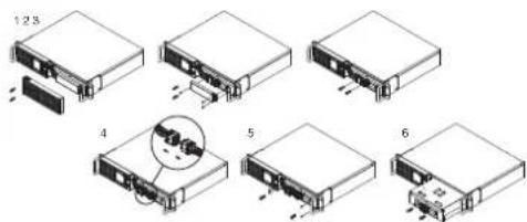
- Remove the right side front panel.
- Remove the three retaining screws for the cable protection cover and remove the cover.
- Remove the two retaining screws from the cable connectors.
- Disconnect the black and red cable.
- Remove the four retaining screws holding the battery pack in place.
- Remove the battery pack.
- Install the new battery pack. Assemble the screws, cover, cable and front panel in the reverse order of the previous steps. Charge the unit for 4-8 hours to ensure the UPS performs expected runtimes.
MODEL: CSN27U12V-NA2, CSN27U12V-NA3, CSN27U12V-NA3-G, CSN27U12V-XL
natural_image
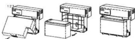
Technical line drawings of three different electronic devices or enclosures (no text or symbols visible)- Remove the battery cover.
- Disconnect battery cable connector to remove battery.
- Replace with new battery and re-connect the battery connector.
- Make sure battery is fixed properly in the compartment and close the battery cover.
MODEL: DTC36U12V-NA3-G
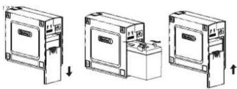
natural_image
Three-step diagram showing a device with labeled components and directional arrows (no text or symbols)- Slide off the battery cover at the back of the DTC36U12V unit.
- Remove the battery from the enclosure.
- Disconnect both battery cable connectors.
- Install the new battery by connecting the red lead to the positive
terminal and the black lead to the negative terminal. - Slide the battery back into the normal operation.
- Replace battery cover to resume normal operation.
MODEL: CS24C12V2-E
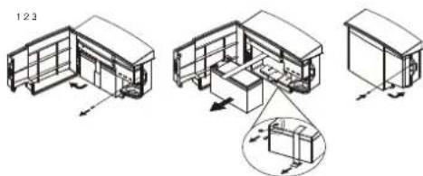
- Remove the case screw.
- Open the battery cover.
- Loosen the battery strap.
- Disconnect battery cable connector to remove battery.
- Replace with new battery and re-connect the battery connector
- Tighten the battery strip
- Close the battery cover and lock the case screw.
CyberPower®
Cyber Power Systems, Inc.
www.cyberpower.com
For USA and Canada:
4241 12th Ave East, Suite 400
Shakopee, MN 55379
Toll-free: (877) 297-6937
For all other regions:
Please visit our website for local contact information.


Brand : CyberPower
Model : RB1270X4A
Category : Battery