Pit Fire 400 X 800 - Heating Real Flame - Free user manual and instructions
Find the device manual for free Pit Fire 400 X 800 Real Flame in PDF.


| Product Type | Outdoor Gel Fuel Fire Pit |
| Brand | Real Flame |
| Model | Pit Fire 400 X 800 |
| Dimensions (W x D x H) | 400 mm x 800 mm x 200 mm (approx.) |
| Weight | 15 kg (approx.) |
| Fuel Type | Gel fuel canisters |
| Heat Output | 30,000 BTU (approx.) |
| Material | Steel body with powder coating |
| Ignition Type | Manual (use long lighter) |
| Safety Features | Stable base, heat-resistant handles, flame guard |
| Cleaning | Wipe with damp cloth; avoid abrasives |
| Maintenance | Remove ash after each use; inspect for damage |
| Spare Parts | Gel fuel canisters (12 oz size) |
| Repairability | Contact Real Flame support for replacement parts |
| Warranty | 1 year limited warranty |
| Assembly Required | Minimal assembly (attach legs if applicable) |
| Recommended Use | Outdoor patio or garden |
Frequently Asked Questions - Pit Fire 400 X 800 Real Flame
User questions about Pit Fire 400 X 800 Real Flame
0 question about this device. Answer the ones you know or ask your own.
Ask a new question about this device
Download the instructions for your Heating in PDF format for free! Find your manual Pit Fire 400 X 800 - Real Flame and take your electronic device back in hand. On this page are published all the documents necessary for the use of your device. Pit Fire 400 X 800 by Real Flame.
USER MANUAL Pit Fire 400 X 800 Real Flame
natural_image
Simple line drawing of a mechanical lifting device with a hook and lever (no text or symbols)PIT FIRE SERIES
INSTALLATION & OPERATING MANUAL
The Pit Fire series is suitable to be installed into a masonry or fireproof base, in outdoor installations only. Designed to operate on Natural or LPG gases only. Approval no.GMK10130
Installed primarily as a decorative appliance. Not certified as a Space Heater.
VERSION 20
WARRANTY INFORMATION
The benefits provided to you under the following warranty are in addition to any other rights and remedies available to you under the law.
1. Warranty
If:
(a) during the first 15 years from the date of purchase (Firebox Warranty Period), there is a defect in the firebox of the Gas Burner; or
(b) during the first 2 years from the date of purchase (Parts Warranty Period), there is a defect in the gas valves or other parts of the Gas Burner.
due to improper workmanship or material, Glen Dimplex will replace or repair the Gas Burner without charge. Any replacement product is warranted only for the time remaining on the original Firebox Warranty Period or the Parts Warranty Period as relevant.
2. Registration
You must register to receive the benefit of this warranty by completing the warranty registration on our website (www.realflame.com.au) or completing and mailing the attached registration card within 30 days of purchase of your Gas Burner (or, if the Gas Burner is fitted to a new home, within 30 days of the date of settlement of purchase of such new home).
3. Exclusions
Glen Dimplex is not obliged to replace or repair the Gas Burner under clause 1 if:
(a) it has been improperly stored, installed, connected, used, operated or repaired, or damaged, abused, tampered with, altered (without our written approval), or not maintained in strict accordance with our installation and operating instructions; or
(b) it has been installed in an outdoor setting.
4. Limit of Liability
The warranty provided under this warranty is limited to replacement or repair of the Gas Burner only, at our option. To the extent permitted by law, Glen Dimplex excludes liability for consequential loss or any other loss or damage caused to property or persons arising from any cause whatsoever, and damage arising from normal wear and tear.
5. Claiming under the Warranty
In order to claim under this warranty you must, within the Firebox Warranty Period or the Parts Warranty Period (as relevant), contact Glen Dimplex, providing the original proof of purchase and the details below:
Supplier Name
Date Of Purchase / settlement of property if new home ____
Model / Serial Number
This warranty does not cover the cost of claiming under the warranty or transporting the Gas Burner to and from the supplier.
Our goods come with guarantees that cannot be excluded under the Australian Consumer Law. You are entitled to a replacement or refund for a major failure and for compensation for any other reasonably foreseeable loss or damage. You are also entitled to have the goods repaired or replaced if the goods fail to be of acceptable quality and the failure does not amount to a major failure.
If you would like to speak to someone about your Gas Burner or claiming under this warranty, please contact the Service Warranty Desk on 1300 554 155.
Glen Dimplex Australia Pty Ltd ACN 69 118 275 460
Head Office: 1340 Ferntree Gully Road, Scoresby 3179
Telephone: (03) 8706 2000 Facsimile: (03) 876 2001
INSTALLATION NOTICE
The installation of this appliance is only to be carried out by an authorised person in accordance with the Manufacturers Instructions, local gas fitting regulations, AS/NZS5601.1-2013 installation code for gas burning appliances and any other relevant statutory regulations.
In all cases the installation of this appliance shall meet the requirements as set out in AS/NZS5601.1-2013.
NOTE: A slight smell may be apparent for the first few hours of use. This is due to the heat resistant paint curing. In some instances a slight discolouration may occur inside the firebox. This is a normal condition and is not covered by warranty.
IMPORTANT SAFETY NOTICES
■ DO NOT PLACE ARTICLES ON OR AGAINST THIS APPLIANCE.
■ DO NOT USE OR STORE FLAMMABLE MATERIAL NEAR THE APPLIANCE.
■ DO NOT SPRAY AEROSOLS IN THE VICINITY OF THIS APPLIANCE WHILST IT IS IN OPERATION.
■ DO NOT MODIFY THIS APPLIANCE.
THIS APPLIANCE IS DESIGNED TO OPERATE WITH LUMINOUS FLAMES. THIS MAY EXHIBIT SLIGHT CARBON DEPOSITS. THIS IS A NORMAL CONDITION AND IS NOT COVERED BY WARRANTY.
WARNING
This pit fire has a naked flame, care should be taken when it is operating if children or the infirm are in close proximity. A safety screen is recommended if constant supervision is not possible. It is recommended that a secondary guard complying with AS-NZS2286 be installed.
The appliance is not intended for use by persons (including children) with reduced physical, sensory or mental capabilities, or lack of experience and knowledge, unless they have been given supervision or instruction concerning use of the appliance by a person responsible for their safety. Children should be supervised to ensure that they do not play with the appliance.
THIS IS PRIMARILY A DECORATIVE APPLIANCE AND IS NOT CERTIFIED AS A SPACE HEATER.
CONTENTS
Contents 4
Dataplate ....5
Dimensions....6
Installation instructions ....7
Wiring Diagrams ....14
Commissioning procedure ....16
Media Installation....17
Operation - User Instructions....20
Troubleshooting ....20
Conversion details ......21
Parts List....22
Glen Dimplex contact information....24
DATA PLATE (Affixed to the gas valve controller cover of the appliance.)
OFRT800x400
| Gas Injector Size (mm) TPP N.G.C. (Mj/Hr) |
| Natural Gas 4.00mm 0.85kPa 75 |
| LPG 2.40mm 2.40kPa 75 |
OFSQ600
| Gas Injector Size (mm) TPP N.G.C. (Mj/Hr) |
| Natural Gas 4.00mm 0.95kPa 80 |
| LPG 2.40mm 2.60kPa 80 |
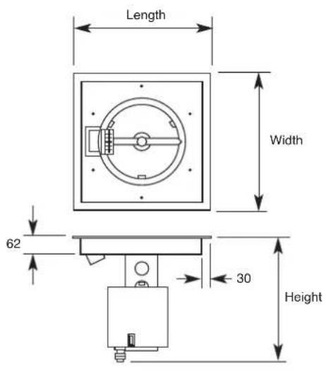
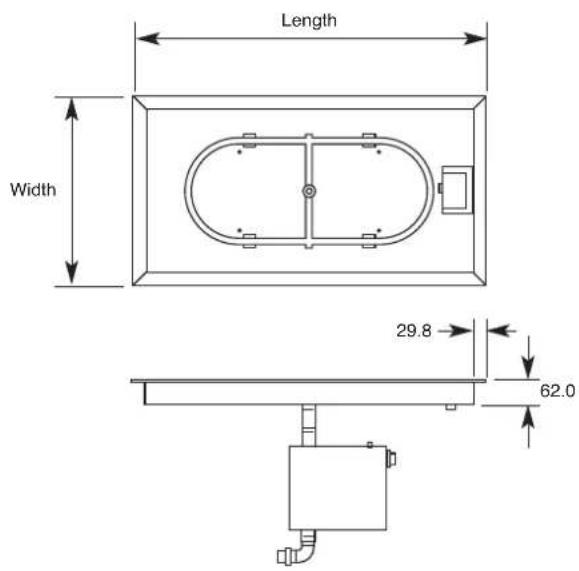
DIMENSIONS
| MODEL FLANGE DIM FLANGE DIAMETER HEIGHT |
| OFRT800 X 400 860 460 450 |
| OFSQ600 660 660 450 |

INSTALLATION INSTRUCTIONS
Location
Select a location where the outdoor fire can be supervised during operation.
The outdoor fire is suitable for outdoor use only and must not be used indoors.
An isolation switch must be fitted at the appliance or on an adjacent wall to allow for emergency shutdown and maintenance.
Installation must meet Australian gas codes AS/NZS5601.1-2013.
Do not install under trees or overhanging branches.
Do not install under eaves, overhang or ceilings.
Ensure adequate space around the fire to enjoy the flame from a safe distance from the heat and flame.
Appliance should be covered or protected in wet weather. Not suitable for use in wet or windy weather.
CLEARANCES FROM COMBUSTIBLES - ALL MODELS
Above1500 mm
Sides200 mm
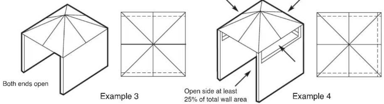
This appliance shall only be used in an above ground open air situation with natural ventilation, without stagnant areas, where gas leakage and products of combustion are rapidly dispersed by wind and natural convection.
Any enclosure in which the appliance is used shall comply with the following:
- An enclosure with walls on all sides, but at least one permanent opening at ground level and no overhead cover.
- Within a partial enclosure that includes an overhead cover and no more than two walls.
- Within a partial enclosure that includes an overhead cover and more than two walls the following shall apply.
* at least 25% of the total wall area is completely open, and
* at least 30% of the remaining wall area is open and unrestricted
- In the case of balconies, at least 20% of the total wall area shall be and remain open and unrestricted.
This appliance shall not be used or installed indoors.
The following figures are diagrammatical representations of outdoor areas.

natural_image
Four technical line drawings of geometric and architectural components: a 3D box, a rectangular frame, a 3D umbrella with diagonal bracing, and a 2D grid (no text or symbols)Example 1 Example 2
INSTALLATION INSTRUCTIONS (continued)

Construction of Enclosure
- Enclosure must be stable and be constructed of non combustible materials.
- Enclosure and fire must be installed above ground level and have adequate drainage.
- The enclosure must have a minimum of 2 vents with each vent having a total open area of 11000mm^2 . Vents are to be located at the upper and lower sections of the enclosure. (EG 73mm × 150mm ) or larger. Ventilation allows for residual heat and unburnt gases to escape the enclosure.
An access panel / door must be fitted to allow access/ servicing of the gas valve and controller. Recommended access door size 300 x 400mm or larger.
Where valve assembly cannot be reached a manhole access panel may be required.
All appliances must have an isolation gas valve fitted, accessible and external to the appliance enclosure.
Lighting Instructions

Rotate gas knob to pilot position.
Push knob in and hold to spark.
Once pilot is alight, hold knob in for a further 10 seconds.
Release knob and rotate to the on position.
To turn the appliance off, rotate the knob to the off position.
INSTALLATION INSTRUCTIONS (continued)
Optional Ignition Methods
For 240 volt and 24 volt options, an electrical isolation switch must be fitted at the appliance or on an adjacent wall to allow for emergency shutdown and maintenance.
An on/off burner switch is located on the front face of the control box below the burner. An auxiliary switch can be located as follows – supplied and wired by installer.
- Weatherproof 240V switch accessible at appliance enclosure.
- Weatherproof 24V switch accessible at appliance enclosure.
- 240V or 24V switch located in residence or nearby switch enclosure wired to appliance (must be installed where appliance can be viewed).
- (Wet areas) Air pressure switch located near enclosure with air line back to controller. (Must be specified at time of ordering)
Drainage holes at base of enclosure are required for water runoff.
150mm clearance underneath valve box is required for ventilation.
The gas control must not be located lower than the ventilation opening.
The gas control must not be lower than ground level, or installed where a buildup of gas may occur. Failure to adequately vent around the controller and enclosure may cause an explosion.
Gas fire pits must be assessed and certified to AS 5263.0 Gas appliances and the below additional requirements.
- Gas fire pits must be constructed such that the burner is at a minimum height of 0.7m above the ground.
- A gas fire pit with a burner less than 1m above the ground must be guarded to the full height of the flame such that a child aged between 0 and 2 years of age cannot gain access to the flame when assessed in accordance with IEC Guide 117.
- A guard incorporated into an appliance to comply with requirement 2 (above) must be an integral part of the appliance.
All necessary information concerning the touchable surfaces of the equipment, including the following, shall be gathered:
* Classification of surface temperatures as hot, moderate or cold;
- Material and texture of the surface;
- All normal operating conditions of the equipment including the setting that results in maximum temperatures of the touchable surfaces;
- The probability of contact, taking into account the arm's reach of a person shown in Figure 1 and Table 1.
| Age (Years) | Arm's reach in the vertical direction (see (a) of Figure 1) measured from the floor (m) |
| Children less than 2 years | 1.00 |
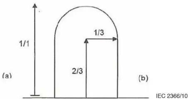
Figure 1 - Arm's reach
The distance is interpreted as either a fully stretched person (a) or a person reaching for an item (b)
The worst case of either (a) or (b) shall be used
Table 1 - Gives guidance on arm's reach
INSTALLATION INSTRUCTIONS (continued)
Examples of enclosures

INSTALLATION INSTRUCTIONS (continued)
Optional Glass Surrounds
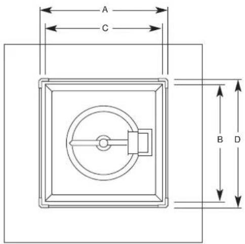
Note: When installing the optional glass surrounds to your pit fire, use the B and C dimensions for centre to centre measurements for 5mm pilot hole.

natural_image
Pure structural diagram of a beam supported at both ends, no text or symbols present| MODEL ABCD |
| OFSQ600 670 670 710 710 |
| OFRT800 X 400 520 870 560 910 |
INSTALLATION INSTRUCTIONS (continued)
Examples of enclosures

INSTALLATION INSTRUCTIONS (continued)
APPLIANCES INCORPORATING INTEGRAL LPG SUPPLY SYSTEMS
Cylinder retention
Lateral movement shall not exceed 25mm at the retention means. Any movement shall not transmit strain to rigid tubing or pipe connections.
ENCLOSURES FOR INTEGRAL LPG SUPPLY SYSTEMS
Ventilation of cylinder enclosure
Ventilation openings shall:
(a) be provided at high and low levels; and
(b) have a total free area at high level of not less than 10,000mm ^2 ; and
(c) have a total free area at low level of not less than 6,000mm ^2 ; or
(d) consist of perforations with a total free area of not less than 25% of the sidewall area.
The bottom of the low level (set of) opening(s) shall be at the enclosure base with the upper edge no more than 125mm above the base.
Accessibility of cylinder valve
The cylinder valve shall be readily accessible for manual operation. A door in the enclosure to gain access to the cylinder valve is acceptable provided it is non-locking and can be opened without the use of tools. An easily removable cover is also acceptable.
Installing cylinders
(a) Cylinders should be installed on a firm, level, non-combustible base, and not resting on soil. The floor or base should be constructed so that water cannot accumulate within any enclosure or recess.
(b) Cylinders should not be stacked on top of each other.
(c) Any cylinder that is liable to accidental dislodgment should be prevented from falling.
(d) Cylinders should not be installed below ground level unless there is sufficient ventilation to prevent the accumulation of any leaking gas.
(e) A cylinder should be installed so that the pressure-relief valve is in contact with the vapour space and, where practicable, any discharge from this valve is directed away from any adjacent cylinders or combustible structures.
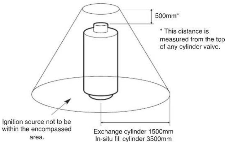
Clearances around cylinders
INSTALLATION INSTRUCTIONS (continued)
Construction of Enclosure (continued)
TYPICAL MASONRY / BRICKWORK SURROUND
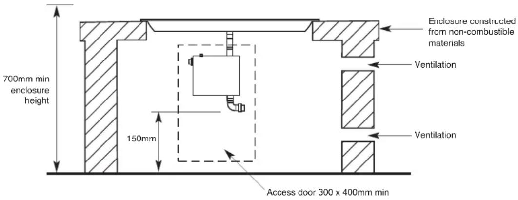
TYPICAL FIXED TABLE / FABRICATED ENCLOSURE
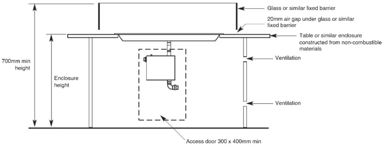
NOTE - The enclosure must have 2 vents of at least 11000mm2 per vent. (EG 73mm x 150mm) or larger.
Warranty requirement – The enclosure must be constructed on a stable surface.
The weight of the appliance must be supported by the pan, not by the control box.
The appliance must be installed level.
The interior of the enclosure must not be filled with any media. Keep all area around tray and valve enclosure free and well ventilated.
LPG gas cylinders must not be stored in the enclosure.
LPG storage enclosures must meet the requirements of AS/NZS5601.1-2013.
It is recommended that reconstituted stone be kept away from the heat and flame, due to the risk of cracking. The manufacturer is not responsible for damage.
Note – Radiant heat from the appliance may effect certain materials or items stored near or under the appliance and may be seriously damaged.
INSTALLATION INSTRUCTIONS (continued)
- Note appliance gas type – Natural gas or LPG. Should the appliance be the incorrect gas type please contact the supplier.
• Gas isolation valve is to be accessible and located outside the enclosure.
- Ensure wiring to the appliance is protected and not creating a hazard.
• Installers – Please ensure the installation and instruction manuals supplied with this appliance are supplied to the customer and the customer is trained on how to operate the appliance correctly.
- Do not modify the appliance.
- Do not exceed maximum rated pressures.
- Appliance must be installed with gas installation code (AS/NZS5601.1-2013) and applicable electrical installation code (AS3000).
- Test for gas leaks prior to operating appliance.
- Check gas pressures and adjust if incorrect.
- Auxiliary switch locations. – Auxiliary on/off switches must located to enable viewing of the fireplace operation.
- Appliance must be supervised at all times during operation.
WIRING DIAGRAMS
Optional 240v Directly wired
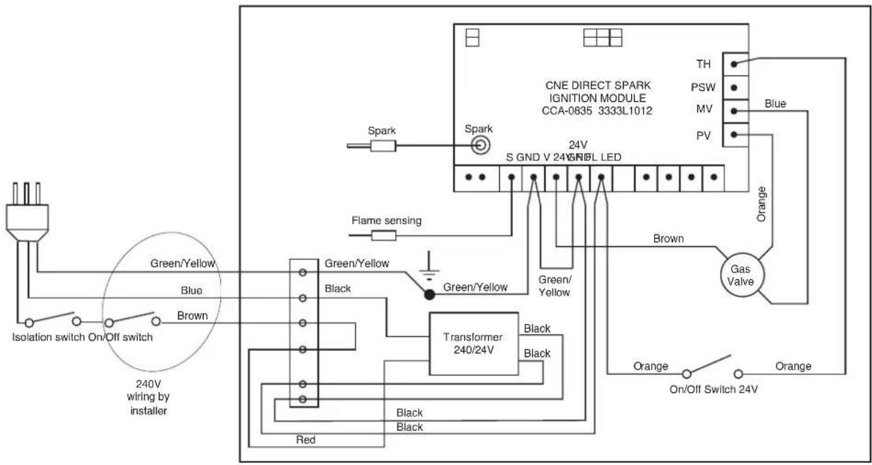
flowchart
graph TD
    A["Power Supply"] --> B["Isolation switch On/Off switch"]
    B --> C["Green/Yellow"]
    B --> D["Blue"]
    B --> E["Brown"]
    B --> F["240V wiring by installer"]
    C --> G["Green/Yellow"]
    C --> H["Black"]
    C --> I["Transformer 240/24V"]
    I --> J["Red"]
    I --> K["Black"]
    I --> L["Black"]
    G --> M["Spark"]
    H --> N["Flame sensing"]
    I --> O["Green/Yellow"]
    I --> P["Black"]
    M --> Q["CNE DIRECT SPARK IGNITION MODULE CCA-0835 3333L1012"]
    N --> Q
    Q --> R["TH"]
    Q --> S["PSW"]
    Q --> T["MV"]
    Q --> U["PV"]
    Q --> V["Blue"]
    Q --> W["Orange"]
    Q --> X["Gas Valve"]
    X --> Y["Orange"]
    X --> Z["On/Off Switch 24V"]
    style A fill:#f9f,stroke:#333
    style Q fill:#ccf,stroke:#333
    style R fill:#fff,stroke:#333
    style S fill:#fff,stroke:#333
    style T fill:#fff,stroke:#333
    style U fill:#fff,stroke:#333
    style V fill:#fff,stroke:#333
    style W fill:#fff,stroke:#333
    style X fill:#fff,stroke:#333
    style Y fill:#fff,stroke:#333
    style Z fill:#fff,stroke:#333
Optional 24v Wall mounted transformer kit

Warning – Improper installation, adjustment, alteration or lack of maintenance and servicing can result in personal injury and or property damage. Read all installation, operating and maintenance instructions thoroughly before installing, servicing or operating the appliance.
COMMISSIONING PROCEDURE (prior to installing media)
Once the outdoor fire is installed.
- Check for gas leaks.
- Carry out the lighting procedure.
- Check burner pressures and adjust as per Dataplate.
- Turn appliance off.
• Install media as per media installation instructions.
- Turn on appliance.
- Allow appliance to run for 45 minutes to dry out and burn off the media. - A safe distance of 5 metres should be observed during this period. The media may emit steam, crack and spit during this time.
- Once the media has been burnt off, turn off the appliance.
MEDIA INSTALLATION
Volcanic Rock
Fill tray with media or until all burners tubes are covered by one layer of media. Spread evenly around tray.
Do not cover pilot area.
Do not overfill with media above the pilot cover level.
Warning – new or wet media may cause spitting of hot material from the fire and may present a burns risk.
Warning - New rock media or wet media should be fired for approx 45 minutes prior to normal use to prevent unwanted spitting. A safe distance of 5 metres should be observed during this period.
Do not overload with media and smother flame.
Do not use any other media than as supplied and recommended by the manufacturer. Use of other media may result in explosive media which may cause injury or damage.
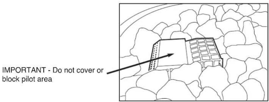
IMPORTANT - Do not cover or block pilot area
MEDIA INSTALLATION (continued)
Glass media
Fill tray with volcanic rock the rock level reaches the bottom of the burner tubes.
Lay glass media on top of volcanic rock until burner tubes are covered by one layer of glass media. Spread evenly around tray.
Do not cover pilot area.
Do not overfill with media above the pilot cover level.
Do not overload with media and smother flame.
Do not use any other media than as supplied and recommended by the manufacturer. Use of other media may result in explosive media which may cause injury or damage.
Glazed pebbles
Fill tray with glazed pebbles until all burners tubes are covered by one layer of media. Spread evenly around tray.
Do not cover pilot area.
Do not overfill with media above the pilot cover level.
Warning – new or wet media may cause spitting of hot material from the fire and may present a burns risk.
Warning - New media or wet media should be fired for approx 45 minutes prior to normal use to prevent unwanted spitting. A safe distance of 5 metres should be observed during this period.
Do not overload with media and smother flame.
Do not use any other media than as supplied and recommended by the manufacturer. Use of other media may result in explosive media which may cause injury or damage.
Do not cover or block pilot cap ventilation holes.
MEDIA INSTALLATION (continued)
Volcanic Rock with ceramic logs
Appliance must be fitted with Ceramic log kit.
Fill tray with volcanic rock as per above instructions.
Do not cover pilot area.
Do not overfill with rock above the pilot cover level.
Place logs on top of volcanic rock in a random stacking arrangement.
Warning – new or wet media may cause spitting of hot material from the fire and may present a burns risk.
Warning - New rock media or wet media should be fired for approx 45 minutes prior to normal use to prevent unwanted spitting. A safe distance of 5 metres should be observed during this period.
Do not overload with media and smother flame.
Do not use any other media than as supplied and recommended by the manufacturer. Use of other media may result in explosive media which may cause injury or damage.
NOTE – Appliance incorporates a live fuel effect, and is designed to operate with luminous flames, slight carbon deposits may be exhibited.
The use of ceramic logs may require regular cleaning to remove carbon buildup.
OPERATION – USER INSTRUCTIONS
Do not operate if you smell gas. Turn appliance off, extinguish any open flame. Contact your installer or a licensed gasfitter.
When fire is not in use turn off gas and power to appliance.
Fire must be covered when not in use.
Do not use if any part of this appliance has been submerged in water. Contact your installer or a qualified service technician.
Solid fuels must not be burnt in the fire. Leaves, sticks, wood, paper food or material must be kept away from the fire.
Do not use as a starter for solid fuels.
Before lighting check for gas leaks.
- Ensure gas supply is turned on.
- Ensure electrical supply is turned on. If 240v or 24v option fitted.
- Switch appliance on at on/off isolation switch. If 240v or 24v option fitted.
- Wait for pilot to ignite. (Upto 45 seconds)
- Main burner will ignite automatically.
Should burner fail to ignite. Wait 5 minutes and reattempt.
Should reattempts fail to ignite burner please contact your installer or licensed gasfitter for service.
Warning – New or wet rock media may cause spitting of hot material and steam from the fire and may present a burns risk or personal injury risk. Maintain a safe distance of 5 metres minimum until media is adequately dried or burnt off. This may take up to 45 minutes of operation.
Note – Both children and adults should be alerted to the hazards of high temperature surfaces and open flames. A safe distance should be maintained to prevent burns and ignition of clothing.
It is recommended that a secondary guard complying with AS/NZS 2286 be installed.
The appliance should be inspected and serviced every 24 months by an authorised technician.
Appliance operates with luminous flames, carbon deposits may need to be cleaned regularly.
TROUBLESHOOTING
| Symptom | Possible Cause |
| Pilot won’t light | Check gas is turned on.Check electrical is turned on.Check for spark at electrode, check lead connection. |
| Pilot lights but main burner does not ignite | Check rocks not blocking pilot flame.Faulty thermogenerater. – contact service. |
| Main flame is very little or very large | Check gas pressure – contact installer or licensed gas fitter.Blocked or dirty injector – contact service technician.Incorrect or low gas supply. |
| Main flame is very yellow and tall | Aeration blocked – Clean appliance, contact service technician. |
CONVERSION DETAILS
Natural gas to propane.
- Turn appliance off.
- Turn gas supply off.
- Disconnect gas from valve inlet connection.
- Remove fire assembly from enclosure.
- Unscrew pilot assembly from valve.
- Remove ignition wires from pilot.
- Unscrew valve assembly from burner and tray.
- Unscrew and remove aeration - injector fitting.
- Replace aeration – injector fitting with correct gas type. Ensure connections are tight with no gas leaks.
- Remove pilot assembly and replace with correct gas type.
- Reattach valve assembly. Ensure connections are tight with no gas leaks.
- Reattach pilot assembly tubes and wires.
- Remove Natural gas regulator spring from valve.
- Replace regulator spring with correct gas type spring.
- Refit assembly to enclosure.
- Connect gas to inlet connection.
- Check for gas leaks.
- Fill tray with rock media.
- Start appliance and adjust burner pressure to correct pressure.
- Remove manometer and tighten gas test point.
- Check for gas leaks.
- Turn appliance off.
PARTS LIST
| 1 Valve | |
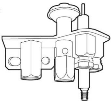
| 2 | SIT Pilot assembly Natural gas |
| SIT Pilot assembly Propane | |
| 3 Injector Natural gas | |
| Injector ULPG | |
| 4 Gas controller CNE CCA-0835 | |
1

natural_image
Technical line drawing of a mechanical assembly (no text or symbols)2
natural_image
Technical line drawing of a mechanical component with threaded shaft and housing (no text or symbols)3

natural_image
Technical line drawing of a threaded pipe fitting (no text or symbols)4

natural_image
Technical line drawing of an electronic device front panel with no visible text or symbols
www.realflame.com.au
1300 554 155
- PIT FIRE SERIES
- INSTALLATION & OPERATING MANUAL
- WARRANTY INFORMATION
- Warranty
- Registration
- Exclusions
- Limit of Liability
- Claiming under the Warranty
- INSTALLATION NOTICE
- IMPORTANT SAFETY NOTICES
- WARNING
- CONTENTS
- DATA PLATE (Affixed to the gas valve controller cover of the appliance.)
- DIMENSIONS
- INSTALLATION INSTRUCTIONS
- Location
- CLEARANCES FROM COMBUSTIBLES - ALL MODELS
- Construction of Enclosure
- INSTALLATION INSTRUCTIONS (continued)
- Optional Ignition Methods
- Examples of enclosures
- APPLIANCES INCORPORATING INTEGRAL LPG SUPPLY SYSTEMS
- Cylinder retention
- ENCLOSURES FOR INTEGRAL LPG SUPPLY SYSTEMS
- Ventilation of cylinder enclosure
- Accessibility of cylinder valve
- Installing cylinders
- Clearances around cylinders
- WIRING DIAGRAMS
- COMMISSIONING PROCEDURE (prior to installing media)
- MEDIA INSTALLATION
- Volcanic Rock
- MEDIA INSTALLATION (continued)
- Glass media
- Glazed pebbles
- Volcanic Rock with ceramic logs
- OPERATION – USER INSTRUCTIONS
- CONVERSION DETAILS
- Natural gas to propane.
- PARTS LIST
Brand : Real Flame
Model : Pit Fire 400 X 800
Category : Heating