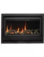
Inspire 700 - Heating Real Flame - Free user manual and instructions
Find the device manual for free Inspire 700 Real Flame in PDF.


| Product Type | Electric Fireplace Heater |
| Model | Inspire 700 |
| Brand | Real Flame |
| Heating Power | 1500 W (5100 BTU/h) |
| Voltage | 120 V AC, 60 Hz |
| Heating Area | Up to 400 sq. ft. |
| Dimensions (W x H x D) | 36.2 x 20.5 x 11.8 inches (92 x 52 x 30 cm) |
| Weight | 35.3 lbs (16 kg) |
| Flame Effect | LED flame with adjustable brightness and color |
| Heating Modes | High heat, low heat, fan only |
| Thermostat | Adjustable thermostat (60-82°F / 15-28°C) |
| Remote Control | Yes, includes battery |
| Timer | 1-9 hours auto shut-off |
| Installation | Freestanding or wall-mounted |
| Safety Features | Overheat protection, tip-over switch, cool-touch glass |
| Material | Steel body with glass front |
| Color | Black (or as available) |
| Power Cord Length | 6 ft (1.8 m) |
| Certifications | UL Listed, ETL |
| Warranty | 1 year limited warranty |
Frequently Asked Questions - Inspire 700 Real Flame
User questions about Inspire 700 Real Flame
0 question about this device. Answer the ones you know or ask your own.
Ask a new question about this device
Download the instructions for your Heating in PDF format for free! Find your manual Inspire 700 - Real Flame and take your electronic device back in hand. On this page are published all the documents necessary for the use of your device. Inspire 700 by Real Flame.
USER MANUAL Inspire 700 Real Flame
natural_image
3D CAD model of a rectangular enclosure or enclosure frame with mounting holes and a flat panel (no text or symbols)INSPIRE FLAME EFFECT SPACE HEATER
MODELS 700/900/1100
INSTALLATION & OPERATING MANUAL
The Inspire space heater is suitable to be installed into a frame out installation.
Designed to operate on Natural gas and LPG gas. Approval no.GMK 10528
WARRANTY INFORMATION
The benefits provided to you under the following warranty are in addition to any other rights and remedies available to you under the law.
1. Warranty
If:
(a) During the first 15 years from the date of purchase (Firebox Warranty Period), there is a defect in the firebox of the Gas Burner; or
(b) During the first 2 years from the date of purchase (Parts Warranty Period), there is a defect in the gas valves or other parts of the Gas Burner, due to improper workmanship or material, Glen Dimplex will replace or repair the Gas Burner without charge. Any replacement product is warranted only for the time remaining on the original Firebox Warranty Period or the Parts Warranty Period as relevant.
2. Registration
You must register to receive the benefit of this warranty by completing the warranty registration on our website (www.realflame.com.au) or completing and mailing the attached registration card within 30 days of purchase of your Gas Burner (or, if the Gas Burner is fitted to a new home, within 30 days of the date of settlement of purchase of such new home).
3. Exclusions
Glen Dimplex is not obliged to replace or repair the Gas Burner under clause 1 if:
(a) It has been improperly stored, installed, connected, used, operated or repaired, or damaged, abused, tampered with, altered (without our written approval), or not maintained in strict accordance with our installation and operating instructions; or
(b) It has been installed in an outdoor setting.
4. Limit of Liability
The warranty provided under this warranty is limited to replacement or repair of the Gas Burner only, at our option. To the extent permitted by law, Glen Dimplex excludes liability for consequential loss or any other loss or damage caused to property or persons arising from any cause whatsoever, and damage arising from normal wear and tear.
5. Claiming under the Warranty
In order to claim under this warranty, you must, within the Firebox Warranty Period or the Parts Warranty Period (as relevant), contact Glen Dimplex, providing the original proof of purchase and the details below:
Supplier Name
Date of Purchase / settlement of property if new home ____
Model / Serial Number
This warranty does not cover the cost of claiming under the warranty or transporting the Real Flame Gas Burner to and from the supplier
Our goods come with guarantees that cannot be excluded under the Australian Consumer Law. You are entitled to a replacement or refund for a major failure and for compensation for any other reasonably foreseeable loss or damage. You are also entitled to have the goods repaired or replaced if the goods fail to be of acceptable quality and the failure does not amount to a major failure.
If you would like to speak to someone about your Gas Burner or claiming under this warranty, please contact the
Service Warranty Desk on 1300 554 155.
Glen Dimplex Australia Pty Ltd ACN 69 118 275 460
Head Office: 1340 Ferntree Gully Road, Scoresby 3179
Telephone: (03) 8706 2000 Facsimile: (03) 8706 2001
WARNING
The Inspire space heater has a primary safety glass fitted in front of the glass door. This safety glass is fitted to this appliance to reduce the risk of injury from burns and at no time should this glass be permanently removed.
For protection of young children or the infirm, a secondary guard is required.
The appliance is not intended for use by persons (including children) with reduced physical, sensory or mental capabilities, or lack of experience and knowledge, unless they have been given supervision or instruction concerning use of the appliance by a person responsible for their safety. Children should be supervised to ensure that they do not play with the appliance.
WARNING
The outer glass panel gets extremely hot! Precaution should be taken and young children supervised at all times when heater is operating
INSTALLATION NOTICE
- The installation of this appliance is only to be carried out by an authorized person in accordance with the Manufacturer's Instructions, local gas fitting regulations, AS/NZS5601.1-2013 installation code for gas burning appliances and any other relevant statutory regulations.
- Do not modify this appliance
- In all cases the installation of this appliance shall meet the requirements as set out in AS/NZS5601.1-2013.
- Do not install in a fireplace as a Type 1 installation.
NOTE: A slight smell may be apparent for the first few hours of use. This is due to the heat resistant paint curing. It is recommended to open windows in the room for the first lighting of the fire. In some instances, a slight discolouration may occur inside the firebox. This is a normal condition and is not covered by warranty.
IMPORTANT SAFETY NOTICE
• DO NOT PLACE ARTICLES ON OR AGAINST THIS APPLIANCE.
• DO NOT USE OR STORE FLAMMABLE MATERIALS IN OR NEAR THIS APPLIANCE
• DO NOT SPRAY AEROSOLS IN THE VICINITY OF THIS APPLIANCE WHILST IT IS IN OPERATION
- CARE MUST BE TAKEN TO ENSURE THAT ANY RETURN AIR REGISTER OR EXHAUST SYSTEM DOES NOT ADVERSLEY AFFECT THE OPERATION OF THE APPLIANCE OR DRAUGHT OF CHIMNEY OR FLUE.
- APPLIANCE IS DESIGNED TO OPERATE WITH LUMINOUS FLAMES. MAY EXHIBIT SLIGHT CARBON DEPOSIT
SERVICING
It is recommended you service your gas fire every 2 years as a minimum.
CORD REPLACEMENT
Electrical cord replacement must be undertaken by qualified and trained personnel only
Table of Contents
WARRANTY INFORMATION 0
DATA PLATE 4
Inspire 700....4
Inspire 900....4
Inspire 1100....4
DIMENSIONS....4
Inspire 700....5
Inspire 900....5
Inspire 1100....6
Power Flue 6
LOCATION....7
INSTALLATION CLEARANCES....7
INSTALLATION CODES....7
FLUE CONFIGURATIONS .... 7
FLUE TERMINATION LOCATION....8
SETUP WITH EXTERNAL WALL MOUNTED FAN TERMINAL 10
ROOFTOP POWERFLUE TERMINATION 14
Insulation requirements for flue runs 14
TIMBER FRAME INSTALLATION 20
MEDIA INSTALLATION 22
MEDIA TYPES 22
COMMISSIONING PROCEDURE 36
OPERATION – USER INSTRUCTIONS 36
DATA PLATE (Affixed to the base of the unit for reference to gas pressure & consumption)
Inspire 700
| GAS TYPE | INJECTOR SIZE | TPP | N.G.C. (MJ/hr) |
| Natural Gas | 1 X 2.30mm | 0.88kPa High0.40kPaLow | 22.0 High/16.0 Low |
| LPG | 1 X 1.35mm | 2.48kPa High1.58kPaLow | 22.0 High/17.0 Low |
Inspire 900
| GAS TYPE | INJECTOR SIZE | TPP | N.G.C. (MJ/hr) |
| Natural Gas | 1 X 2.45mm | 0.89kPa high0.42kPa Low | 24.0 High/16.0 Low |
| LPG | 1 X 1.45mm | 2.49kPa High1.58kPaLow | 24.0 High/19.0 Low |
Inspire 1100
| GAS TYPE | INJECTOR SIZE | TPP | N.G.C. (MJ/hr) |
| Natural Gas | 1 X 2.65mm | 0.88kPa High0.41kPaLow | 29.0 High/20.0 Low |
| LPG | 1 X 1.50mm | 2.45kPa High1.51kPaLow | 27.0 High/21.0 Low |
Max - Min inlet pressure range
Natural gas: 1.13kPa - 5.00 kPa
LPG: 2.75kPa - 5.00 kPa
Note: Gas pressures are not adjustable on the Inspire models.
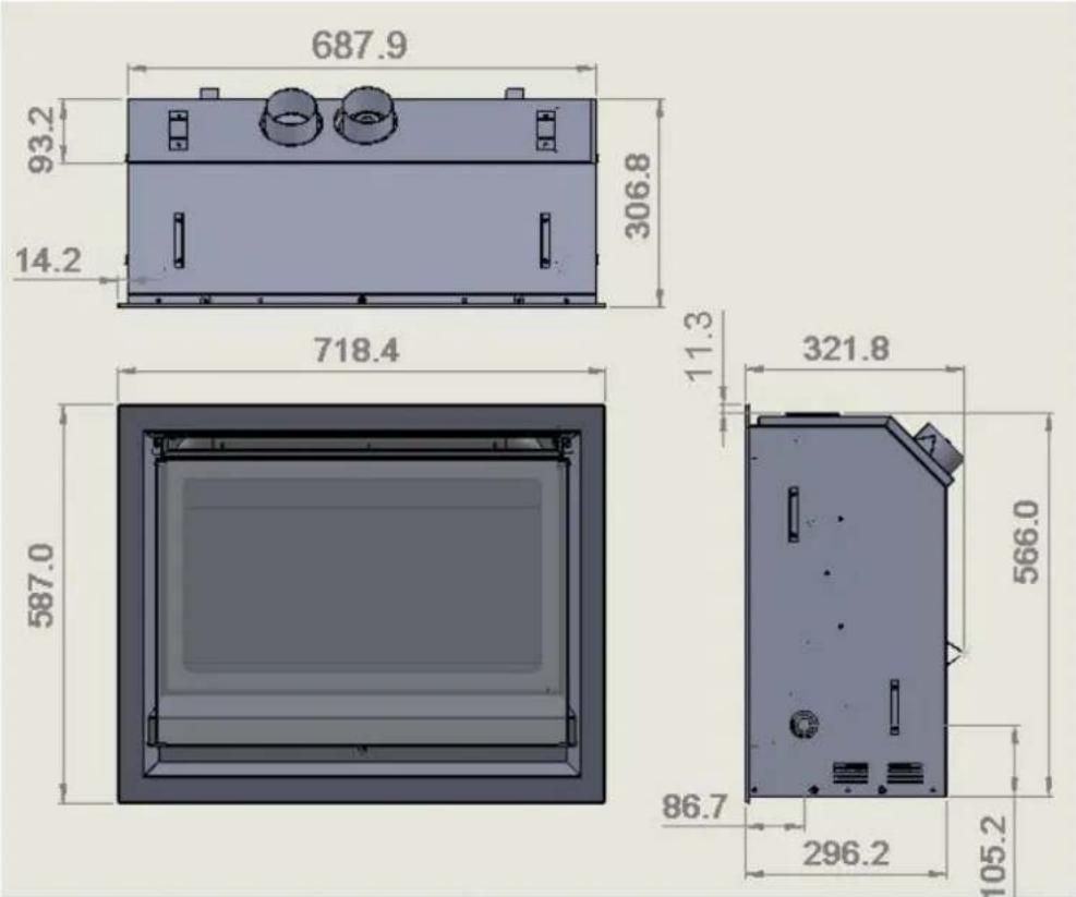
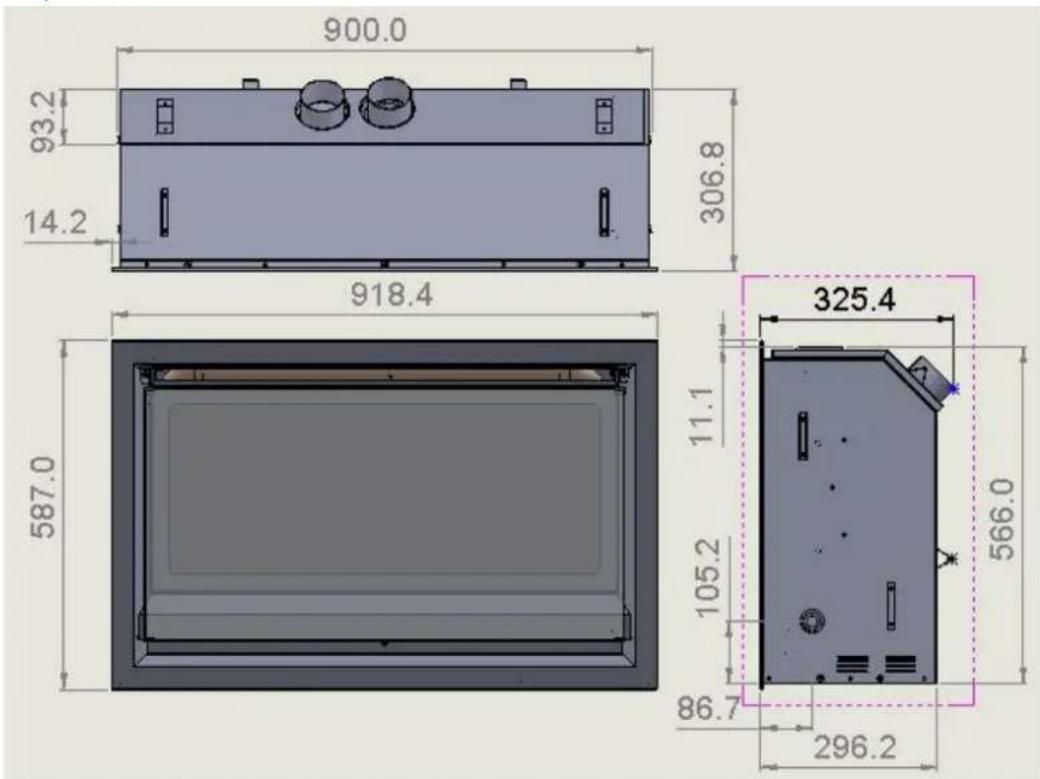
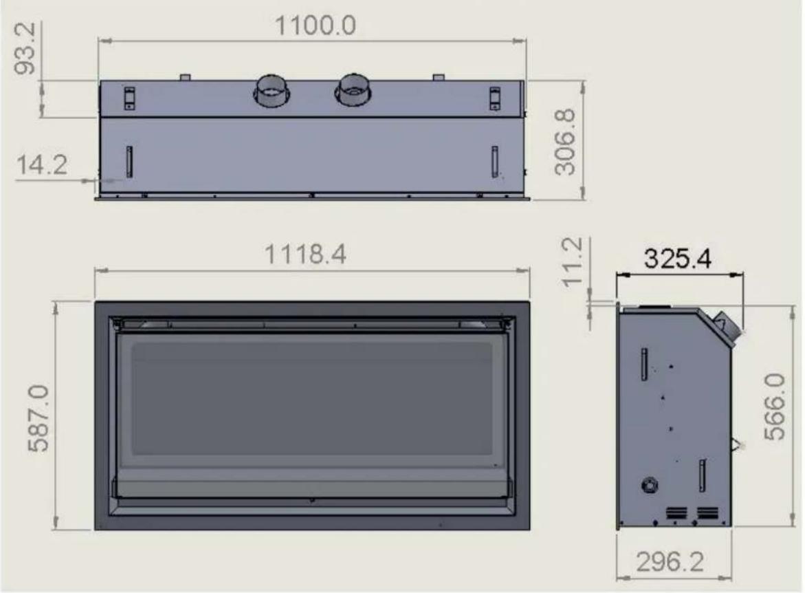
DIMENSIONS
Gas and electrical connection cut-out dimensions for all models

Inspire 700
Inspire 900
Inspire 1100
Power Flue

LOCATION
Select a location where the fire can be supervised during operation.
An electrical isolation switch must be fitted at the appliance or on an adjacent wall to allow for emergency shutdown and maintenance.
Installation must meet Australian gas codes AS/NZS 5601.
INSTALLATION CLEARANCES – Clearances from combustible materials
Floor - 0mm Sides - 5mm Top - 5mm
Flue outer - 25mm Front - 250mm Back - 25mm
INSTALLATION CODES
Installers – Please ensure the installation and instruction manuals supplied with this appliance are supplied to the customer and the customer is trained on how to operate the appliance correctly.
Do not modify the appliance.
Do not exceed maximum rated pressures.
Appliance must be installed as per gas installation code (AS/NZS 5601) and applicable electrical installation code (AS3000).
Test for gas leaks prior to operating appliance. Check gas pressures and adjust if incorrect.
WARNING - Transit material such as cardboard packaging, pallet, plastic wrap, glass packaging warning labels and burner media protection must be removed prior to use.
FLUE CONFIGURATIONS
-
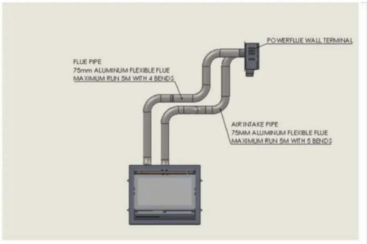
Wall mount powerflue module: Flue configurations are a maximum of 5m, flue runs less than 5m are permitted.
-
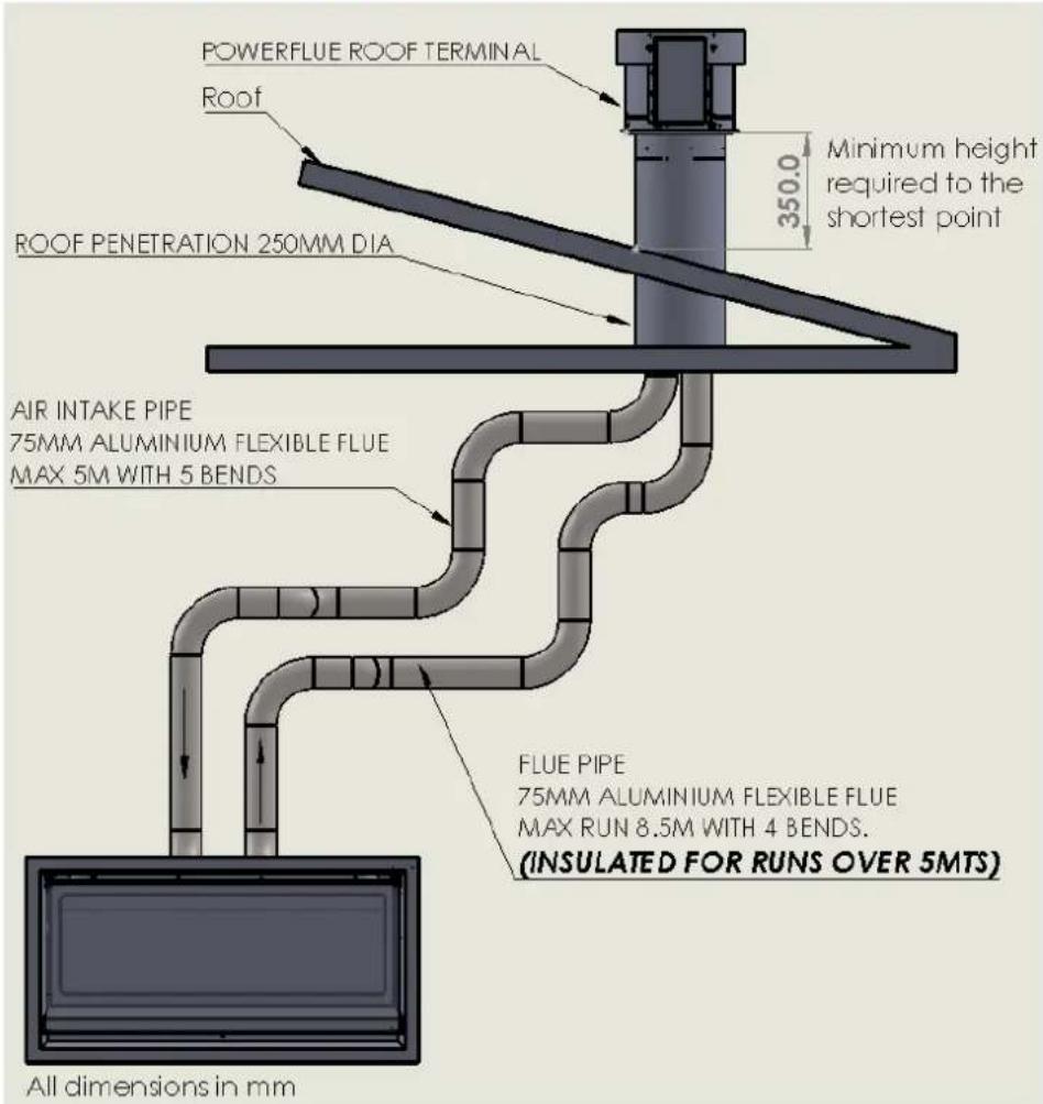
Rooftop powerflue termination: Flue configurations are a maximum of 8.5m, flue runs less than 8.5m are permitted. Refer Rooftop termination section for more details and installation instructions.
Aluminium flexible flue is used for both the inlet and outlet.
Flue runs 5m or 8.5m or less (75mm diameter Aluminium flexi flue)
Inlet pipe - Maximum flue run 5m or 8.5m total length including 5 x 90 bends
Outlet pipe - Maximum flue run 5m or 8.5m total length including 4 x 90 bends
Appliance is supplied with a 2 x 5m or 2 x 8.5m flexible flue lengths. Flue can be cut to length as required.
Recommended bend radius 150mm or larger. Bends must not form a P Trap.
Flue must be clipped and supported support. Connections must be sealed with silicon and clamped where advised.
Recommended Silicon – Non acetic, neutral cure 200degrees or higher temperature rated. Bostik RTV 926 or similar.

natural_image
Pure electrical circuit lines without any symbolsU style flue runs must not be installed
- Flue terminations shall not be recessed in walls or sidings.
- EXTREMELY IMPORTANT: In heavy snow areas take extra care to prevent blocking flue termination with snow removal equipment.
- Flue gases exiting flue terminals are very hot and must not be restricted to assure fireplace combustion is not affected.
- Do not place, build any obstruction, plant any bushes or for any reason attempt to conceal the flue termination. To do so will affect the operation of the fireplace and may be hazardous
- This unit must always vent directly to outdoors.
GAS CONNECTION –
15mm (1/2") Compression union
ELECTRICAL CONNECTION – 3 Pin 10 Amp GPO plug
POWER RATING OF APPLIANCE - 230V 50Hz 0.8Amp
INSPIRE FLUE TERMINAL LOCATION

LEGEND:
T = Flue terminal
I = Mechanical air inlet
M = Gas meter
P = Electricity meter or fuse box
Shading indicates prohibited areas for flue terminals
| Ref. | Item | Minimum clearances (mm) | |
| Natural draft | Fan assisted | ||
| a | Below eaves, balconies and other projections: | ||
| • Appliances up to 50 MJ/h input | 300 | 200 | |
| • Appliances over 50 MJ/h input | 500 | 300 | |
| b | From the ground, above a balcony or other surface † | 300 | 300 |
| c | From a return wall or external corner † | 500 | 300 |
| d | From a gas meter (M) (see 4.7.11 for vent terminal location of regulator) | 1000 | 1000 |
| e | From an electricity meter or fuse box (P) | 500 | 500 |
| f | From a drain pipe or soil pipe | 150 | 75 |
| g | Horizontally from any building structure † or obstruction facing a terminal | 500 | 500 |
| h | From any other flue terminal, cowl, or combustion air intake † | 500 | 300 |
| j | Horizontally from an openable window, door, non-mechanical air inlet, or any other opening into a building with the exception of sub-floor ventilation: | ||
| • Appliances up to 150 MJ/h input | 500 | 300 | |
| • Appliances over 150 MJ/h input up to 200 MJ/h input | 1500 | 300 | |
| • Appliances over 200 MJ/h input up to 250 MJ/h input † | 1500 | 500 | |
| • Appliances over 250 MJ/h input † | 1500 | 1500 | |
| • All fan-assisted flue appliances, in the direction of discharge | - | 1500 | |
| k | From a mechanical air inlet, including a spa blower | 1500 | 1000 |
| n | Vertically below an openable window, non-mechanical air inlet, or any other opening into a building with the exception of sub-floor ventilation: | ||
| • Space heaters up to 50 MJ/h input | 150 | 150 | |
| • Other appliances up to 50 MJ/h input | 500 | 500 | |
| • Appliances over 50 MJ/h input and up to 150 MJ/h input | 1000 | 1000 | |
| • Appliances over 150 MJ/h input | 1500 | 1500 | |
† Unless appliance is certified for closer installation
NOTES:
1 All distances are measured to the nearest part of the terminal.
2 Prohibited area below electricity meter or fuse box extends to ground level.
3 See Clause 5.13.6.6 for restrictions on a flue terminal under a covered area.
4 See Appendix J, Figures J2(a) and J3(a), for clearances required from a flue terminal to an LP Gas cylinder. A flue terminal is considered to be a source of ignition.
5 For appliances not addressed above acceptance should be obtained from the technical regulator
SETUP WITH EXTERNAL WALL MOUNTED FAN TERMINAL
natural_image
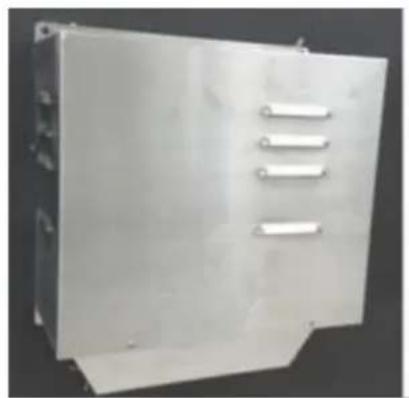
Exterior view of a metallic industrial enclosure with three horizontal slots (no text or symbols visible)Wall mounted fan module – terminal must be installed with clearances as specified by AS/NZS 5601.1 Clause 6.9.3
Run exhaust flue and air intake flue as required
Maximum run 5mts. Flues can be run next to each other. Maintain the required clearances to combustibles.

natural_image
Close-up of a transparent cylindrical object with concentric rings, held by a hand (no text or symbols visible)Connection to appliance Cut tube to length where required. Ensure ends are burr free and round, test fit flue will slide over connection.
natural_image
Close-up of a black cylindrical container with a white adhesive tape applied to its side (no text or symbols visible)
natural_image
Close-up of a coiled metallic pipe with a white tool inserted, placed on a wooden surface (no text or symbols visible)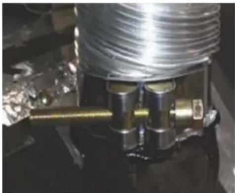
natural_image
Close-up of a mechanical component with coiled spring and brass fitting (no visible text or symbols)
natural_image
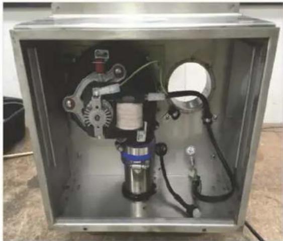
Interior view of an open industrial enclosure with visible internal components and wiring (no text or symbols)Recommended Silicon – Non-acetic, neutral cure 150deg or higher temperature rated. Bostik RTV 926 or similar.
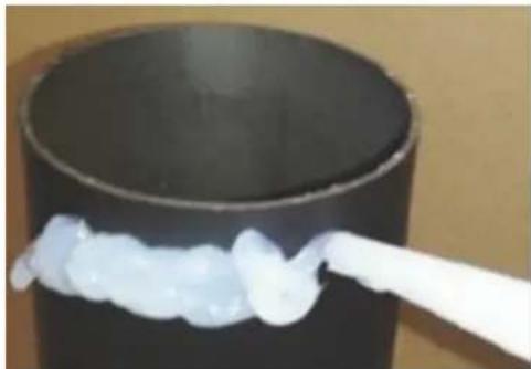
Apply an 8mm thick silicon bead fully around heater connection approx. 10mm from the top.
Apply an 8mm thick silicon bead fully around the lower fan connection spigot approx. 10mm from the end.
Apply an 8mm silicon bead fully around the inside of the flue end (heater connection end) Fit flue clamp over flue (loosely).
Slide flue onto connection spigot fully. Tighten clamp fully. Wipe excess silicon, visually check connection to ensure connection is fully sealed.
Repeat above with air intake flue pipe to heater connection.
Clip flues as required to provide adequate support.
Connection to wall mounted fan terminal
Predrill mounting holes into wall.
Remove cover from fan terminal
 | Cut flue exhaust tube (hot tube) to length (approximately flush with wall exit). Wall termination will sit against wall.Pull flue tube through approx. 100mm further (will be pushed back once terminal fitted). |
 | Feed power cable through wall and into wall terminal. |
 | Slide flue onto connection spigot fully. Tighten clamp fully. Wipe excess silicon, visually check connection to ensure connection is fully sealed. |
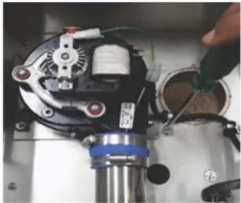
 | Feed air intake flue pipe through location spigot and fit retaining screw. |
natural_image
Close-up of a mechanical assembly with a hand holding a green tool, no visible text or symbolsPush fan terminal into position. And affix to wall. Uneven or rough surfaces may require sealant along top and side gaps.
Connect power cable connector. Fit cable clamp to cable.

natural_image
Exterior view of a metallic industrial enclosure with three vertical slots (no text or symbols visible)Fit front cover
ROOFTOP POWERFLUE TERMINATION
Insulation requirements for flue runs
NOTE:
• Insulation is used for rooftop termination installations only
• The insulation supplied is in lengths of 1000mm
- The termination must be installed at a minimum height of 350mm from the lowest point of the termination to closest point on the roof (Refer image above)
- The termination's spigot and the roof penetration pipe is 250mm in diameter.
| Flue length | Insulation Requirement |
| 0 - 5 mts | Uninsulated flue run |
| 5 – 8.5 mts | Insulated flue run * |
* For 5 - 8.5-meter flue runs, only the supplied insulation must be used and only the exhaust pipe is to be insulated. The initial 300mm from the appliance exit and the last 700mm from the rooftop termination may remain uninsulated. However, it is recommended to insulate as much of the total length as possible.
Example: For a flue run of 8.5mts
Flue run length N = 8.5mts
Minimum insulation required X = N - 1 mts
$$ = 8. 5 - 1 = 7. 5 \mathrm{mts} $$
Insulation is supplied in lengths of 1000mm.
Initial 300mm from appliance exit may remain uninsulated (Refer image below) Last 700mm from rooftop termination down may remain uninsulated.
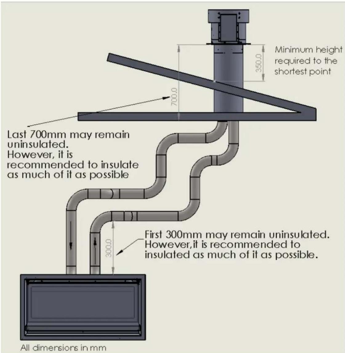
Note: The insulation can be cut to shorter lengths to allow for bends.
Instructions:
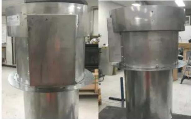 | Rooftop fan module – Terminal must be installed with clearances as specified by AS/NZS 5601.1 Clause 6.9.3Run exhaust flue and air intake flue as requiredMaximum run 8.5mts. Flues can be run next to each other. Maintain the required clearances to combustibles.Insulate flue for runs over 5mts as required. |
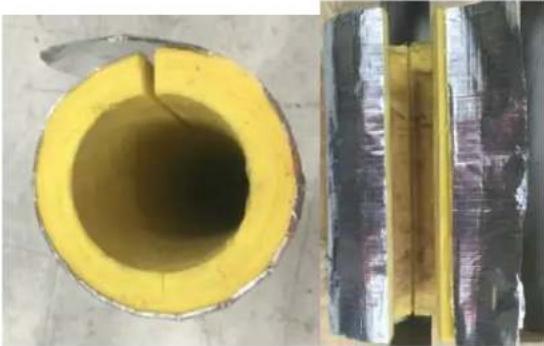 | Rigid glass wool insulation with 25mm wall thickness.The insulation is pre-slit and can be fitted around the flue pipe like a collarIt can also be cut to required size to fit around sharp bends |
 | Run both flexi pipes from the appliance to the roof spaceFit insulation on the flexi pipe as shown.Use aluminium tape to seal the insulation and ensure its fit snug to the pipe.Cut insulation to required sizes to fit around corners. |
 | Insulation cut pattern for 90° bend |
 | For 90° and 45° bends the corners must be insulated.For a 90°bend with a minimum bend radius is 150mm. Cut the insulation diagonally into 3 pieces in a cone shape. |
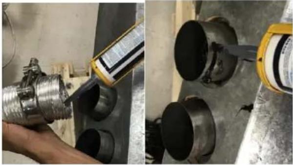 | On the heater connection end - Fit clamp loosely & apply silicon inside the pipes. Apply an 8mm silicon bead fully around the inside of the flue and on the heater spigot. Smear the silicon around the spigot and pipe.Recommended Silicon – Non-acetic, neutral cure 200°C or higher temperature rated. Bostik RTV 922 or similar |
 | Slide flue onto connection spigot fully. Tighten clamp fully. Wipe excess silicon, visually check connection to ensure connection is fully sealed.Repeat above with air intake flue pipe to heater connection.Clip flues as required to provide adequate support. |
 | Insert the roof penetration and fix firmly to the roof structure using appropriate supports.The roof penetration flue is a 250mm rigid flue. | |
 | Fit the access panel to the roof penetrationUse the screw holes fix the access panel to the roof penetration. | |
 | Run flue pipes through the access cut outs before fitting the termination on for ease of installation.(The picture is a reference only. Take care not to flex/bend the pipe too sharply and risk slitting the pipe)If possible to insulate the flue pipe through the roof penetration, then fit insulation to the exhaust pipe. | |
 | Fit the termination on to the access panel and match the rivet holes to rivet the termination to the access panel.Use only the rivets provided | |
 | On the termination end - Fit clamp loosely & apply silicon inside the pipes. Apply an 8mm silicon bead fully around the inside of the flue and on the flue spigot. Smear smoothly around the surfaces.Recommended Silicon – Non-acetic, neutral cure 200°C or higher temperature rated. Bostik RTV 922 or similar | |
 | Slide flue onto connection spigot fully. Tighten clamp fully. Wipe excess silicon, visually check connection to ensure connection is fully sealed.Ensure that the pipes are connected correctly and are not inverted.Use the labels to identify exhaust and intake spigots | |
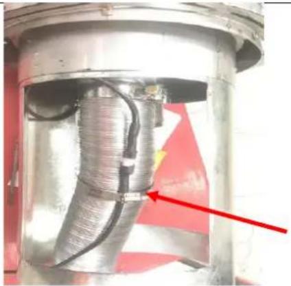 | Connect the fan power cable from the appliance to the termination.Ensure the cable is clamped only to the intake pipe to secure the cable from hanging loose & touching the hot flue gases pipe.Use the clamp provided. The clamp can be opened like a collar and fitted around on the flue. | |
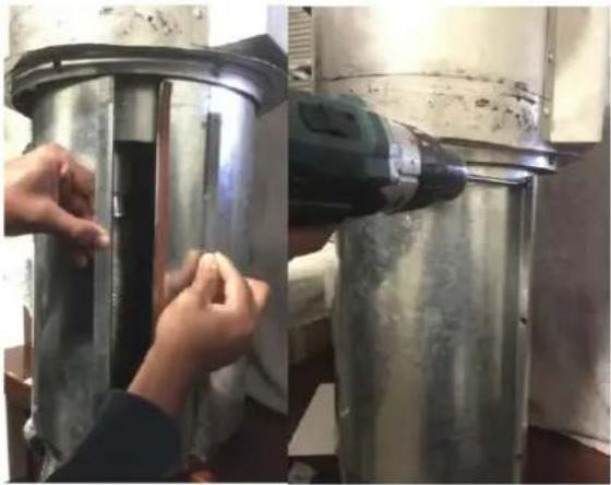 | Flex collar and fit around the access panel. Socket the collar all the way up close to the air intake slots Ensure there is a rubber seal top and bottom of the collar.Use only the screws provided to tightly fit the collar to seal the access panel. | |
TIMBER FRAME INSTALLATION

Frame out Dimensions (in mm)
| A | B | C | D* |
| 580 | 710 | 400 | 1500 |
| 910 | |||
| 1110 |
* Indication only. Can be smaller or larger.
Notes:
- At frame stage the builder shall provide a 10amp GPO to the rear back corner of the frame out with an isolation switch fitted at the appliance or on an adjacent wall within the room where the fire can be seen. An adequate gas line should be run down the front right hand side of the frame out terminating approximately 1m from the base, this should be run down the inside face of the timber.
TIMBER FRAME INSTALLATION - PRE HANDOVER OPTION (continued)
Notes (continued):
-
Pre plastering, the installer shall install the termination (vertical or horizontal) run the twin 75mm ID flues from the termination to inside the frame out (label them exhaust and intake) and terminate 500mm from the base. (Do not fix). A 15mm (1/2") copper connection should then be fixed to the gas line with 90 deg elbow and tail that will be able to be pulled into the front right hand corner of the appliance at pre hand over stage. The control loom should be fitted at the fan motor and run into the frame out and terminate to the front left hand side of the base. Coil any excess at this point. The frame out can now be plastered and finished.
-
For pre hand over final install, the plaster should be cut out using the template supplied. Then sit the appliance in position on the base. Push the left hand side of the appliance back allowing room to plug the 3 pin lead into the GPO provided and to connect the control loom. Then return appliance to square and push the right side back to retrieve the 15mm gas connection, feed it into the hole provided. Now pull the 2 x 75mm ID flues onto the spigots at the rear of the fire, fix and tighten. (Ensure you connect the intake and exhaust to the correct spigot). Pull the appliance back to square and fit off the gas connection.
Follow the commissioning procedures noted on page 31 and fit off the front glass and trim set.
MEDIA INSTALLATION
Media must be setup as per instructions
- The media is designed and shaped to correctly locate and remain in the correct position.
- Do not add extra media, or combine media types.
- Only the approved supplied media is to be used.
- Do not use any other media than as supplied and recommended by the manufacturer.
NOTE: Use of other media may result in explosive media which may cause injury or damage.
MEDIA TYPES
- Driftwood
- Pebbles
Refer to correct section for media set up.
Driftwood Media – Inspire 700 Model
a) Place branch log 1 supports as shown.

natural_image
Interior view of a dark, empty enclosure with a small white animal figurine on the floor (no visible text or symbols)b) Place No 2. Long log across branch log, using location grooves to locate.

natural_image
Two white, elongated objects placed on a dark rectangular frame (no visible text or symbols)c) Place No 3 log short crossover log over the long log, use location groove to locate.
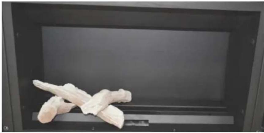
natural_image
Two white food items placed inside a black appliance frame (no visible text or symbols)d) Place log No 4 over log 3, use groove to locate.
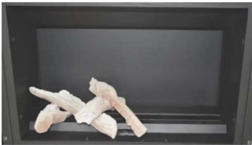
natural_image
Close-up of white, elongated food items on a dark surface (no text or symbols visible)e) Place the second branch log 1 onto support.

natural_image
Close-up of white, elongated food items on a dark surface (no text or symbols visible)f) Place 2nd log No. 2 log onto branch log, use location grooves to locate.

natural_image
Close-up of several white, elongated food items arranged in a triangular pattern inside a black container (no text or symbols visible)g) Place 2 log No 3 onto long log, use location groove to locate.

natural_image
Close-up of white, elongated, organic food items arranged in a pattern on a dark surface (no text or symbols visible)Place mixed coals around logs along front section, DO NOT PLACE ON BURNER.
Pebbles Media - INSPIRE 700 Model

natural_image
Pure electrical circuit lines without any symbolsLocate side trays on either side of the firebox. Ensure that they are sitting flush against the side walls and screw them in from the front (if the trays do not sit flat then use the rear screw holes to screw them down).


Randomly arrange pebbles around the media trays front and back. One medium size pebble to sit on each of the side trays. DO NOT PLACE ANY MEDIA ON THE BURNER
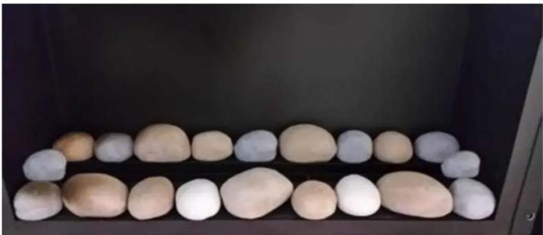
natural_image
Interior view of a dark appliance with multiple small white and beige stone or ceramic pieces arranged in rows (no text or symbols visible)Driftwood media - Inspire 900 Model
a) 900 MODEL - Place Log 5 as shown in the image below. Near LH end.

natural_image
Interior view of a dark, empty storage unit with a small white object on the left side (no visible text or symbols)b) Place log 6 across log 5 using location grooves to locate.

natural_image
Blackboard with two white food items placed on the left side of it (no text or symbols visible)c) Place log 1 as shown in the image below.
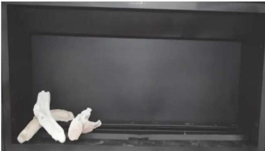
natural_image
Blackboard with three white food items placed on the left (no text or symbols visible)d) Place log 2 across log 1, using location grooves to locate.
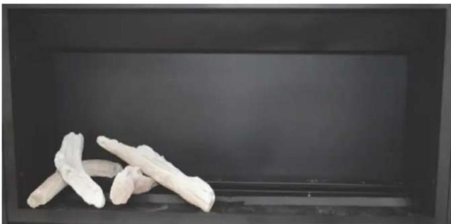
natural_image
Black tray with several white food items, possibly dried mushrooms or meat pieces, placed on a dark surface against a plain black background.e) Place log 3 (short crossover) across log 2, using location groove to locate.
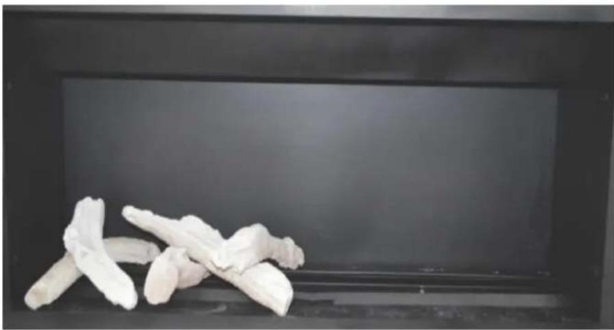
natural_image
Close-up of white ginger root pieces placed on a dark surface against a black background (no text or symbols visible)f) Place log 4 over log 3, using groove to locate.
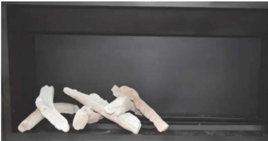
natural_image
Close-up of several white, aged food items placed on a dark surface against a black background (no text or symbols visible)g) Place Log 1 as shown in the image below.

natural_image
Black tray holding several white, irregularly shaped food items (no text or symbols visible)h) Place Log 2 across Log 1, using location grooves to locate.

natural_image
Close-up of several white, elongated food items arranged on a dark surface against a black background (no text or symbols visible)i) Place Log 3 (short crossover) over log 2, using location groove to locate.

natural_image
Close-up of several white, irregularly shaped objects arranged in a row against a dark background (no text or symbols visible)j) Place Log 4 over log 3, use groove to locate.

natural_image
Black tray holding several white meat pieces, possibly pork ribs or mushrooms, arranged on a dark surface (no text or symbols visible)Place mixed coals around logs along front section, DO NOT PLACE ON BURNER.
Driftwood media - Inspire 1100 model
a) Place Log 5 as shown in the image below
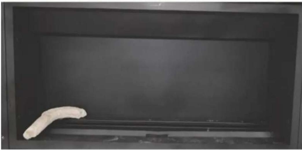
natural_image
Interior view of a dark, empty storage unit with a small white object on the left side (no visible text or symbols)b) Place log 6 across log 5 using location grooves to locate.
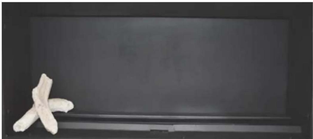
natural_image
Blackboard with two white food items on the left side, no visible text or symbolsc) Place log 1 as shown in the image below.

natural_image
Blackboard with two white banana-shaped objects on a flat surface (no text or symbols visible)d) Place log 2 across log 1, using location grooves to locate.
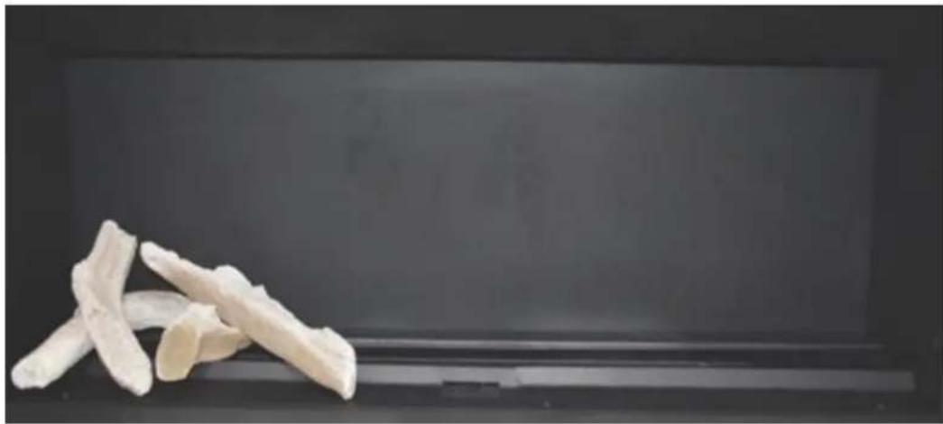
natural_image
Close-up of white food items on a dark surface with a blackboard in the background (no text or symbols visible)e) Place log 3 (short crossover) across log 2, using location groove to locate.

natural_image
Close-up of white banana-shaped objects on a dark surface, no text or symbols visiblef) Place log 4 over log 3, using groove to locate.
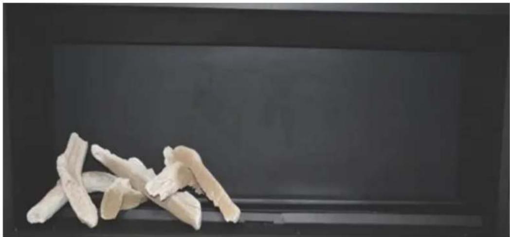
natural_image
Close-up of dried, light-colored food items on a dark surface against a black background (no text or symbols visible)g) Place Log 1 as shown in the image below.
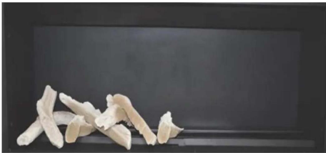
natural_image
Close-up of sliced white food items on a dark surface, no text or symbols visibleh) Place Log 2 across Log 1, using location grooves to locate.

natural_image
Close-up of several white, elongated food items arranged on a dark surface against a black background (no text or symbols visible)i) Place Log 3 (short crossover) over log 2, using location groove to locate.

natural_image
Close-up of sliced white root vegetables on a dark surface against a black background (no text or symbols visible)j) Place Log 4 over log 3, use groove to locate.

natural_image
Close-up of several white, irregularly shaped objects arranged on a dark surface against a black background (no text or symbols visible)k) Place Log 8 as shown in the image below.

natural_image
Close-up of white, irregularly shaped objects arranged on a dark surface against a black background (no text or symbols visible)I) Place log 9 across log 8 as shown

natural_image
Close-up of dried, sliced white root pieces arranged in a row against a dark background (no text or symbols visible)m) Place Log 3 over log 9, use locating groove to locate.

natural_image
Close-up of dried, sliced white root pieces arranged in a row against a dark background (no text or symbols visible)n) Place assorted coals (random placing) on the front plate as shown in the image below.
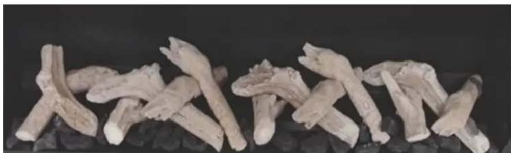
natural_image
Close-up of dried, sliced herbal root pieces arranged on dark stones (no text or symbols visible)Pebble media
a) Ensure the rear media support is firmly located in position

natural_image
Dark rectangular screen with no visible text, symbols, or markingsb) Place pebbles in random colors / size along back support.

natural_image
Row of small round objects on a dark shelf, no visible text or symbolsc) Place front pebbles in random colors / size along front - DO NOT PLACE ANY MEDIA ON BURNER

natural_image
Row of smooth, rounded stones arranged in two rows on a dark surface (no text or symbols visible)COMMISSIONING PROCEDURE
Once the fire is installed.
- Install media.
- Connect to gas and power.
- Fit firebox door.
- Check for gas leaks.
- Connect powerflue module loom to fan control unit.
- Carry out the lighting procedure.
- Check burner pressures and inlet supply pressure (Valve is non-adjustable).
- Check appliance for combustion (CO) leakage.
- Turn off
- Fit trim.
- Handover instructions to owner.
- Instruct owner on how to operate the fireplace safely.
- Instruct owner how to isolate the appliance in an emergency.
OPERATION – USER INSTRUCTIONS
- Do not operate if you smell gas. Turn appliance off, extinguish any open flame.
- Contact your installer or a licensed gasfitter.
- Do not use if any part of this appliance has been submerged in water. Contact your installer or a qualified service technician.
- Solid fuels must not be burnt in the fire. Leaves, sticks, wood, paper food or material must be kept away from the fire.
- Appliance operates with luminous flames; carbon deposits may occur during operation.
Should the appliance fail to ignite or was recently turned off, allow 2 minutes before attempting to reignite appliance.
In the event of abnormal operation please contact your licensed gas installer, gas service personnel or Real Flame Pty Ltd. Abnormal operation may consist of the following, noisy fan, excessive or small flame, unusual flame appearance or colour, excessive sooting or other.
-
Press power button on the remote.
-
Press Temperature button until ON is displayed.
- Set the desired temperature - it must be above the room temperature for the appliance to operate.
- Appliance will start once the flame symbol appears on the remote.
- Appliance will perform a 60 seconds pre-purge, then sparking will occur.
NOTE: Appliance takes up to 60 sec to pre-purge prior to sparking.
• Not all remote control functions are available.
- In the event of loss of power, the appliance will shut down safely. The appliance may automatically resume operation once power is restored, pending the operation mode of the remote control.

Transmitter LCD display
TECHNICAL DATA
Remote Control
| Supply Voltage | 4.5V (three 1.5 V AAA batteries) Ambient |
| Temperature settings | 0 - 50°C |
| Radio frequency | 315 MHz |
WARNING
THE TRANSMITTER AND RECEIVER ARE RADIO FREQUENCY DEVICES. PLACING THE RECEIVER IN OR NEAR METAL MAY SEVERELY REDUCE THE SIGNAL RANGE.
ATTENTION:
- TURN OFF THE MAIN GAS SUPPLY OF THE APPLIANCE DURING INSTALLATION OR MAINTENANCE OF THE RECEIVER DEVICE.
- TURN OFF MAIN GAS SUPPLY TO THE APPLIANCE PRIOR TO REMOVING OR REINSERTING THE BATTERIES.
• IN CASE OF REMOTE CONTROL MALFUNCTION TURN OFF THE IFC DEVICE USING THE ON/OFF SWITCH. - FOR INSTALLATION/MAINTENANCE SWITCH OFF THE IFC DEVICE REMOVING MAIN POWER SUPPLY PLUG.
Temperature indication display
With the system in the OFF position, press the thermostat key and the mode key at the same time. Look at the LCD screen on the transmitter to verify that a C or F is visible to the right of the room temperature display.

Remote control display in Farenheit

Remote control display in Celsius
Turn on the appliance
With the system OFF, press the ON/OFF key on the transmitter. The transmitter display will show some other active icons on the screen. At the same time the receiver will activate the appliance. A single “beep” from the receiver will confirm reception of the command.
Turn off the appliance
With the system ON, press the ON/OFF key on the transmitter. The transmitter LCD display will only show the room temperature. At the same time the receiver will turn off the appliance. A single "beep" from the receiver confirms reception of the command.

Remote control display
Remote flame control
The proflame has six (6) flame levels. With the system ON, and the flame level at the maximum in the appliance, pressing the down arrow key once will reduce the flame height by one step until the flame is turned off.
The up arrow key will increase the flame height each time it is pressed. If the up arrow key is pressed while the system is on but the flame is off, the flame will come on in the high position. A single “beep” will confirm reception of the command.
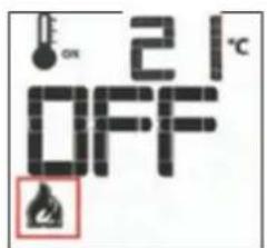
Flame off

Flame Level 1 Flame Level 5 Flame Level Maximum
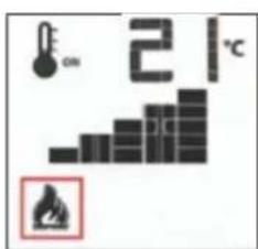

Room thermostat (Transmitter Operation)
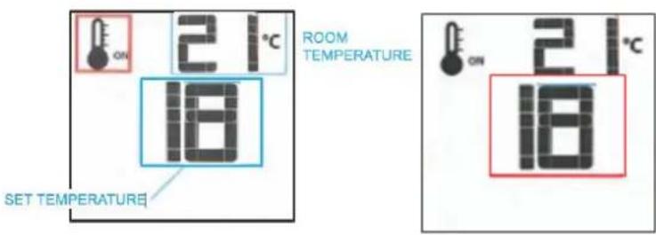
The remote control can operate as a room thermostat. The thermostat can be set to a desired temperature to control the comfort level in a room.
To activate this function, press the thermostat key. The LCD display on the transmitter will change to show that the room thermostat is "ON" and the set temperature is now displayed. To adjust the set temperature, press the up or down arrow keys until the desired set temperature is displayed on the LCD screen of the transmitter.
Smart thermostat (Transmitter Operation)
The smart thermostat function adjusts the flame height in accordance with the difference between the set point temperature and the actual room temperatures. As the room temperature gets closer to the set point the smart function will modulate the flame down. To activate this function, press the thermostat key until the word “SMART” appears to the right of the temperature bulb graphic.
To adjust the set temperature, press the up or down arrow keys until the desired set temperature is displayed on the LCD screen of the transmitter.
Note: When the smart thermostat is activated, manual flame height adjustment is disabled.

Smart flame function
Fan speed control - this function is not supported on this fire.
Remote dimmer control (Light) - this function is not supported on this fire.
Split flow control - this function is not supported on this fire.
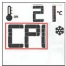
Continuous pilot/intermittent pilot (CPI/IPI) selection
With the system in “OFF” position, press the mode key to index to the CPI mode icon. Pressing the Up arrow key will activate the Continuous Pilot Ignition mode (CPI). Pressing the
Down arrow key will return to IPI. A single "beep" will confirm reception of the command.
NOTE: This fire is designed to run in IPI mode (Intermittent Pilot). The fire is factory preset to operate in this mode.
Should the fire or remote need factory resetting, the IPI mode must be re-selected. Should the remote be in CPI mode or the pilot remains constantly on, please contact Glen Dimplex or your installer to correct the settings.

Key Lock
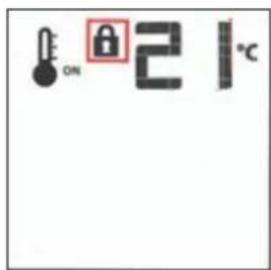
This function will lock the keys to avoid unsupervised operation. To activate this function, press the Mode and Up keys at the same time. To de-activate this function, press the Mode and Up keys at the same time.
Low battery power detection - transmitter
The life span of the remote control batteries depends on various factors: quality of the batteries used, the number of ignitions of the appliance, the number of changes to the room thermostat set point, etc.
When the transmitter batteries are low, a battery icon will appear on the LCD display of the transmitter before all battery power is lost. When the batteries are replaced this icon will disappear.

Remote auxiliary relay control - this function is not supported on this fire.
Changes to the remote settings will not affect or change the appliance operation.


TROUBLESHOOTING
| Problem | Possible Cause | Remedy |
| When remote is activated nothing happens | Remote not talking to receiver | Listen for beep for signal being receivedCheck power to appliance is onCheck batteries in remoteReprogram remote to receiver |
| Fire cuts off and will not relight | Over temperature safety has tripped | Allow fire to cool and reattempt ignition.Check room fan is not blocked.Check fire airflow is not restricted |
| Flame appears low or excessively high | Incorrect gas or pressure | Check test point pressure and supply pressure to appliance.Check gas typeReplace valve if requiredCheck injector for blockage and size |
| Smell in room while operating | Paint curing or firebox door leak | If new appliance - run for several hours, open all room ventilation and allow paint to cure.Turn off appliance and the have door seal inspected by service personnel or Real Flame agent. |
| Room air fan is noisy or not working | Faulty or dirty fan | Fan to be inspected and cleanedReplace fan |
| Appliance operates correctly but pilot remains constantly on. | Remote IPI/CPI incorrectly set | Correct remote control mode to IPI setting. |
TEACHING RF CODE – Reprogramming remote to heater
- Electrical tray must be slid forward to reprogram a remote control.
- Turn the remote to off mode
- Turn mains power to heater on.
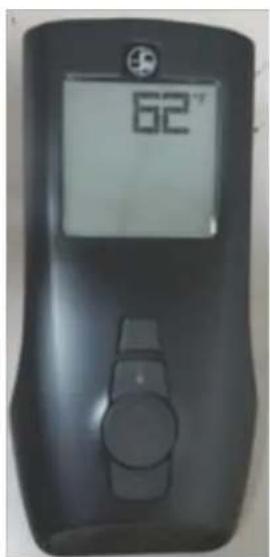
- Press the red button on the receiver once – three beeps should be heard.

- Press the on button on the remote – four beeps should be heard.
- Remote is now connected.
FAULT CODES
Gas Valve controller – no fault codes available. Remote – no faults codes available.
If your fireplace still does not operate correctly consult your dealer, installer or gas service technician. All service and repairs should be performed by an authorised agency All spare parts are available from Glen Dimplex Australia Pty Ltd.
WIRING DIAGRAM

AERATION ADJUSTMENTS and BURNER SIZES
- The primary air is entrained through the aeration cap located at the end of the burner. The aeration cap is factory preset to Natural Gas Driftwood media. Note – for LPG conversion the burner will change - refer table below
| MODEL | NAT GAS | LPG |
| 800 | 26.5 diameter open area | 26.5 diameter open area |
| Inspire 700 Driftwood | 22.0 | 22 |
| Inspire 700 Pebbles | 20.0 | NA |
| Inspire 900 Driftwood | 16.0 | 20.0 |
| Inspire 900 Pebbles | 12.0 | NA |
| Inspire 1100 Driftwood | 22.0 | 26.0 |
| Inspire 1100 Pebbles | 16.0 | NA |
-
Fan restrictor (mounted in outlet tube of power flue fan) - 31.8mm diameter
-
Burner sizes - models for appliance
| Inspire 700 Nat GasInspire 700 LPG | BEKEART Furigas- 0346 | 440mm long | 50mm diameter |
| Inspire 900 Nat Gas | KEEGAS BURNERBE- SS555-527WF-N5 | 555mm long | 50mm diameter |
| Inspire 900 LPGInspire 1100 LPG | BEKAERT- 1647 | 555mm long | 50mm diameter |
| Inspire 1100 Nat Gas | KEEGAS burnerBE-SS800-770WF-N5 | 800mm long | 50mm diameter |
CONVERSION DETAILS - Natural gas /LPG
INSPIRE 700 MODEL
Valve, pilot injector, main burner injector and burner aeration cap must be changed to suit gas type.
VALVE CHANGE
- Turn appliance off.
- Turn gas supply off.
- Remove trim.
- Disconnect gas pipe from isolation valve to burner.
- Remove retaining nuts from electrical tray and slide tray forward.
- Disconnect gas pipe from valve outlet.
- Disconnect valve wires from ignition pack.
- Remove valve from electrical tray (3 retaining screws)
- Remove gas pipe connections from valve and fit to correct gas type valve.
- Reattach valve to mounting plate.
- Reconnect valve wires from ignition pack.
- Reconnect gas pipe to the valve outlet and the inlet pipe.
- Slide electrical tray into position and attach / tighten retaining nuts.
- Connect gas pipe to isolation valve.
- Ensure all connections are tight.
- Connect gas and leak test connections up to the gas valve.
PILOT AND INJECTOR CHANGE
- Remove firebox door (6 screws)
- Remove media from firebox.
- Remove rear media support.
- Remove front media support (2 screws accessed from electrical area)
- Lift out front media support
- Loosen retaining nut from end of burner and lift burner out.
- Remove injector and replace with correct gas type injector, ensure injector is tightened into holder.
- Unclip pilot head and lift off.
- Undo pilot spud using Allen key from above
- Refit correct pilot spud, fully tighten
- Refit fit pilot head and clip into place
- Remove aeration cap from burner and replace with correct model.
- Refit burner – try to rotate burner to ensure burner is in its location slot. Replace holding nut at end of burner and tighten to secure the burner.
- Refit front media support and the side trays
- Refit media as per media setup (refer previous section in instructions)
- Refit firebox door.
- Fit manometer to TPP
- Set pilot adjustment screw as recommended in PILOT ADJUSTMENT SECTION.
- Start appliance and check for gas leaks.
- Start appliance and check burner pressure.
- Check appliance for correct flame operation
- Remove manometer and tighten gas test point.
- Check for gas leaks.
- Check door and appliance for spillage or CO leakage.
- Turn appliance off.
- Refit front trim.
INSPIRE 900 MODEL
Valve, pilot injector, burner, main burner injector and burner aeration cap must be changed to suit gas type.
VALVE CHANGE
- Turn appliance off.
- Turn gas supply off.
- Remove trim.
- Disconnect gas pipe from isolation valve to burner.
- Remove retaining nuts from electrical tray and slide tray forward.
- Disconnect gas pipe from valve outlet.
- Disconnect valve wires from ignition pack.
- Remove valve from electrical tray (3 retaining screws)
- Remove gas pipe connections from valve and fit to correct gas type valve.
- Reattach valve to mounting plate.
- Reconnect valve wires from ignition pack.
- Reconnect gas pipe to the valve outlet and the inlet pipe.
- Slide electrical tray into position and attach / tighten retaining nuts.
- Connect gas pipe to isolation valve.
- Ensure all connections are tight.
- Connect gas and leak test connections up to the gas valve.
PILOT AND INJECTOR CHANGE
- Remove firebox door (6 screws)
- Remove media from firebox.
- Remove rear media support.
- Remove front media support (2 screws accessed from electrical area)
- Lift out front media support
- Loosen retaining nut from end of burner and lift burner out.
- Remove injector and replace with correct gas type injector, ensure injector is tightened into holder.
- Unclip pilot head and lift off.
- Undo pilot spud using Allen key from above
- Refit correct pilot spud, fully tighten
- Refit fit pilot head and clip into place
- Fit correct aeration cap to the correct burner.
- Refit burner – try to rotate burner to ensure burner is in its location slot. Replace holding nut at end of burner and tighten to secure the burner.
- Refit front media support
- Refit media as per media setup (refer previous section in instructions)
- Refit firebox door.
- Fit manometer to TPP.
- Set pilot adjustment screw as recommended in PILOT ADJUSTMENT SECTION.
- Start appliance and check for gas leaks.
- Start appliance and check burner pressure.
- Check appliance for correct flame operation
- Remove manometer and tighten gas test point.
- Check for gas leaks.
- Check door and appliance for spillage or CO leakage.
- Turn appliance off.
- Refit front trim.
INSPIRE 1100 MODEL
Valve, pilot injector, burner, main burner injector, burner aeration cap and rear burner shield must be changed to suit gas type.
VALVE CHANGE
- Turn appliance off.
- Turn gas supply off.
- Remove trim.
- Disconnect gas pipe from isolation valve to burner.
- Remove retaining nuts from electrical tray and slide tray forward.
- Disconnect gas pipe from valve outlet.
- Disconnect valve wires from ignition pack.
- Remove valve from electrical tray (3 retaining screws)
- Remove gas pipe connections from valve and fit to correct gas type valve.
- Reattach valve to mounting plate.
- Reconnect valve wires from ignition pack.
- Reconnect gas pipe to the valve outlet and the inlet pipe.
- Slide electrical tray into position and attach / tighten retaining nuts.
- Connect gas pipe to isolation valve.
- Ensure all connections are tight.
- Connect gas and leak test connections up to the gas valve.
PILOT AND INJECTOR CHANGE
- Remove firebox door (6 screws)
- Remove media from firebox.
- Remove rear media support.
- Remove front media support (2 screws accessed from electrical area)
- Lift out front media support
- Loosen retaining nut from end of burner and lift burner out.
- Remove rear media support plate from rear burner shield.
- Remove rear burner shield from appliance.
- Remove air director and refit screws to plug holes.
- Fit new correct model rear burner shield.
- Fit existing rear media supports back into place.
- Remove injector and replace with correct gas type injector, ensure injector is tightened into holder.
- Unclip pilot head and lift off.
- Undo pilot spud using Allen key from above
- Refit correct pilot spud, fully tighten
- Refit fit pilot head and clip into place
- Fit correct aeration cap to the correct burner.
- Refit burner – try to rotate burner to ensure burner is in its location slot. Replace holding nut at end of burner and tighten to secure the burner.
- Refit front media support
- Refit media as per media setup (refer previous section in instructions)
- Refit firebox door.
- Fit manometer to TPP.
- Set pilot adjustment screw as recommended in PILOT ADJUSTMENT SECTION.
- Start appliance and check for gas leaks.
- Start appliance and check burner pressure.
- Check appliance for correct flame operation
- Remove manometer and tighten gas test point.
- Check for gas leaks.
- Check door and appliance for spillage or CO leakage.
- Turn appliance off & refit the trim.
PARTS LIST
| 1 | Valve |  | ||
| 2 | SIT Pilot assembly | 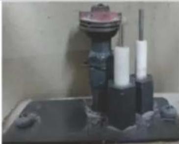 | ||
| 3 | Injector | 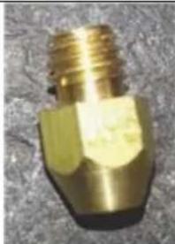 | ||
| 4 | Burner |  | ||
| 5 | Remote control | 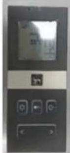 | ||
| 6 | Sit Ignition pack / gas control | 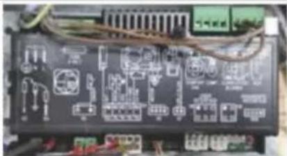 | ||
GLEN DIMPLEX AUSTRALIA PTY LTD
ABN 69 118 275 460
| Head Office/Factory/Showroom1340 Ferntree Gully Rd.Scoresby Vic 3179Ph: (03) 8706 2000 Fax: (03) 8706 2001E-mail: info@realflame.com.au | Richmond - VIC Showroom300 Swan St. Richmond Vic 3121Ph: (03) 9428 4443 Fax: (03) 9428 4445 |
| Dandenong - VIC Showroom3/328 South Gippsland Highway, Dandenong SouthVic 3164Ph: (03) 9702 7853E-mail: sales@realflamedandenong.com.au | Geelong - VIC Showroom1/2A Gordon Avenue. Geelong West Vic 3218Ph/Fax: 5229 0844E-mail: realflamegeelong@hotmail.com.au |
| Sydney - NSW Showroom546 Pacific Highway. Chatswood NSW 2067Ph: (02) 8905 0189 Fax: (02) 8905 0192E-mail: info@realflame.com.au | Miranda - NSW Showroom36 Kareena RdMiranda NSW 2228Ph: (02) 8513 6202 Fax: (02) 9520 1974E-mail: fireplace@realflamesouth.com.au |
| Adelaide - SA Showroom173 -175 Magill Rd. Norwood SA 5067Ph: (08) 8132 0371 Fax: (08) 8132 1687E-mail: realflamesa@iprimus.com.au | Milton - QLD Showroom46 Douglas St, Milton QLD 4064Ph: (07) 3368 2011 |
| Perth – WA Showroom47-53 McDonald St East, Osborne Park WA 6017Ph: (08) 9444 9900 Fax: (08) 9444 9800 | Fyshwick – ACT Showroom88 Wollongong St, Fyshwick ACT 2609Ph: (02) 6280 5522 |
| Ulverstone – TAS Showroom31A Victoria St, Ulverstone TAS 7315Ph: (03) 6425 4440 |
- INSPIRE FLAME EFFECT SPACE HEATER
- MODELS 700/900/1100
- WARRANTY INFORMATION
- Warranty
- Registration
- Exclusions
- Limit of Liability
- Claiming under the Warranty
- WARNING
- INSTALLATION NOTICE
- IMPORTANT SAFETY NOTICE
- SERVICING
- CORD REPLACEMENT
- Table of Contents
- DIMENSIONS
- LOCATION
- INSTALLATION CODES
- FLUE CONFIGURATIONS
- INSPIRE FLUE TERMINAL LOCATION
- NOTES:
- SETUP WITH EXTERNAL WALL MOUNTED FAN TERMINAL
- ROOFTOP POWERFLUE TERMINATION
- Insulation requirements for flue runs
- NOTE:
- Example: For a flue run of 8.5mts
- Instructions:
- TIMBER FRAME INSTALLATION
- TIMBER FRAME INSTALLATION - PRE HANDOVER OPTION (continued)
- Notes (continued):
- MEDIA INSTALLATION
- MEDIA TYPES
- Pebbles Media - INSPIRE 700 Model
- Driftwood media - Inspire 900 Model
- Driftwood media - Inspire 1100 model
- Pebble media
- COMMISSIONING PROCEDURE
- OPERATION – USER INSTRUCTIONS
- TECHNICAL DATA
- Remote Control
- ATTENTION:
- Temperature indication display
- Turn on the appliance
- Turn off the appliance
- Remote flame control
- Room thermostat (Transmitter Operation)
- Smart thermostat (Transmitter Operation)
- Continuous pilot/intermittent pilot (CPI/IPI) selection
- Key Lock
- Low battery power detection - transmitter
- TROUBLESHOOTING
- TEACHING RF CODE – Reprogramming remote to heater
- FAULT CODES
- WIRING DIAGRAM
- AERATION ADJUSTMENTS and BURNER SIZES
- CONVERSION DETAILS - Natural gas /LPG
- INSPIRE 700 MODEL
- VALVE CHANGE
- PILOT AND INJECTOR CHANGE
- INSPIRE 900 MODEL
- INSPIRE 1100 MODEL
- GLEN DIMPLEX AUSTRALIA PTY LTD
- ABN 69 118 275 460
Brand : Real Flame
Model : Inspire 700
Category : Heating