
G4 ThermoPro - Coffee maker Wilbur Curtis - Free user manual and instructions
Find the device manual for free G4 ThermoPro Wilbur Curtis in PDF.


| Product Type | Commercial Coffee Brewer |
| Model | G4 ThermoPro |
| Brand | Wilbur Curtis |
| Dimensions (W x D x H) | 17.5 x 12.5 x 24 inches (approx.) |
| Weight | 28 lbs (approx.) |
| Power Supply | 120V AC, 60Hz, 1500W |
| Brewing Capacity | 1.5 gallons per batch |
| Carafe Type | Triple-insulated stainless steel thermal carafe |
| Brewing System | Advanced aeration system for optimal extraction |
| Water Reservoir | Integrated with sight glass |
| Control Panel | Digital programmable interface with timer |
| Functions | Brew, pause & serve, automatic shutoff, ready-to-serve indicator |
| Maintenance | Daily cleaning of carafe and brew basket; periodic descaling |
| Safety Features | Automatic shutoff, boil-dry protection, cool-touch handle |
| Spare Parts Available | Carafes, brew baskets, water filters, heating elements |
| Warranty | 2 years limited parts and labor |
Frequently Asked Questions - G4 ThermoPro Wilbur Curtis
User questions about G4 ThermoPro Wilbur Curtis
0 question about this device. Answer the ones you know or ask your own.
Ask a new question about this device
Download the instructions for your Coffee maker in PDF format for free! Find your manual G4 ThermoPro - Wilbur Curtis and take your electronic device back in hand. On this page are published all the documents necessary for the use of your device. G4 ThermoPro by Wilbur Curtis.
USER MANUAL G4 ThermoPro Wilbur Curtis
G4 ThermoPro® Series 1.5 Gallon Coffee Brewing System


READ AND SAVE THESE INSTRUCTIONS
NOTICE TO INSTALLER: Please leave this booklet with the machine.
CONTENTS CL24
Key Features/Specifications/System Requirements....FS24
Important Safeguards....IS2
Installation Instructions (General)....II2
Installation Instructions (Leveling, Water Supply, Electrical) ......II9
Operating Instructions ...... Ol11
Cleaning Instructions....CI1
Cleaning Instructions....CI5
Cleaning Instructions....CI9
Programming Guide ...... PG1
Rough-In Drawing....RD30
Illustrated Parts/Recommended Parts IP42
Illustrated Parts/Recommended Parts (Tank Assembly, Single) IP43
Illustrated Parts/Recommended Parts (Tank Assembly, Single, Dual Voltage) IP44
Illustrated Parts/Recommended Parts (Tank Assembly, Twin) IP45
Electrical Schematic (G4TP2S10A3500)......ES49
Electrical Schematic (G4TP2S63A3100, G4TP2S63A3500) ES41
Electrical Schematic (G4TP2S30A3100)......ES50
Electrical Schematic (G4TP2T10A3100, G4TP2T10A3500)......ES42
Electrical Schematic (G4TP2T30A3100)......ES52
Troubleshooting Guide....TG3
Troubleshooting Guide....TG7
Troubleshooting Guide....TG11
Error Codes....EC1
Product Warranty....PW1
Contact Information
Wilbur Curtis Co., Inc.
6913 Acco Street | Montebello, CA 90640 US
Phone: 323-837-2300 | Toll Free: 800-421-6150
Email: csrassistance@wilburcurtis.com | Web: www.wilburcurtis.com
For the latest specifications and information go to www.wilburcurtis.com
Toll Free: 800-995-0417 | Monday - Friday 5:30 A.M. - 4:00 P.M. PT
Email: techsupport@wilburcurtis.com
Due to continued product improvement, the products illustrated/photographed in this guide may vary slightly from the actual product.
Key Features
- Gold Cup ® Series – digital control module provides precise control over all aspects of brewing: time, temperature, volume plus specialty coffee needs from pre-infusion to pulse-brewing to water bypass.
- Generation Four (G4) Digital Control Module – Large, 4.3" touch screen. Icon-driven interface streamlines operation. On-Screen Instructions – Provides fast, intuitive training; reduces service calls.
- Built-in Self Diagnostic System – Includes real-time feedback of the brewing process and energy saving mode.
- Stainless steel ThermoPro vacuum-sealed servers keep coffee fresh, hot and flavorful.
- Pre-Set, One-Touch Global Recipes – Based on coffee type, grind and weight.
- Single unit is field selectable for one, two or three batch brewing.
- Centrally located hot water spout for instant hot beverages and other hot water needs.
- Industry's most effective mineral tolerant design.
Specifications (Selected Models)
Electrical Supply Requirements
| MODEL # | DESCRIPTION PHASE VOLTS AMPS HEATING | AETING | CONFIG WIRE | WATTS | HERTZ GAL/HR | ||||
| G4TP2S10A3500 | Single brewer with shelf | 1 PH | 220 V | 19.5 A | 2 x 2000 W | 3W + G | 4300 W | 50/60 Hz | 12.0 |
| G4TP2S63A3100 | Single brewer, dual voltage | 1 PH | 110/220 V | 15.0/12.7 A | 2 x 1600 W | 2/W3W + G | 1800/2800 W | 50/60 Hz | 4.5/12.0 |
| G4TP2S63A3500 | Single brewer with shelf, dual voltage | 1 PH | 110/220 V | 15.0/12.7 A | 2 x 1600 W | 2/W3W + G | 1800/2800 W | 50/60 Hz | 4.5/12.0 |
| G4TP2T10A3500 | Twin brewer with shelf | 1 PH | 220 V | 23.0/34.5 A | 3 x 2500 W | 3W + G | 5100/7600 W | 50/60 Hz | 15.0/21.0 |
| G4TP2T10A3100 | Twin brewer | 1 PH | 220 V | 23.0/34.5 A | 3 x 2500 W | 3W + G | 5100/7600 W | 50/60 Hz | 15.0/21.0 |
Export
| G4TP2S30A3100 | Single brewer, export | 1 PH | 230 V | 20.0 A | 2 x 2000 W | 2W + G | 4600 W | 50/60 Hz | 12.0 |
| G4TP2T30A3100 | Twin brewer, export | 1 PH | 230 V | 24.2 A | 2 x 2500 W | 2W + G | 5574 W | 50/60 Hz | 21.0 |
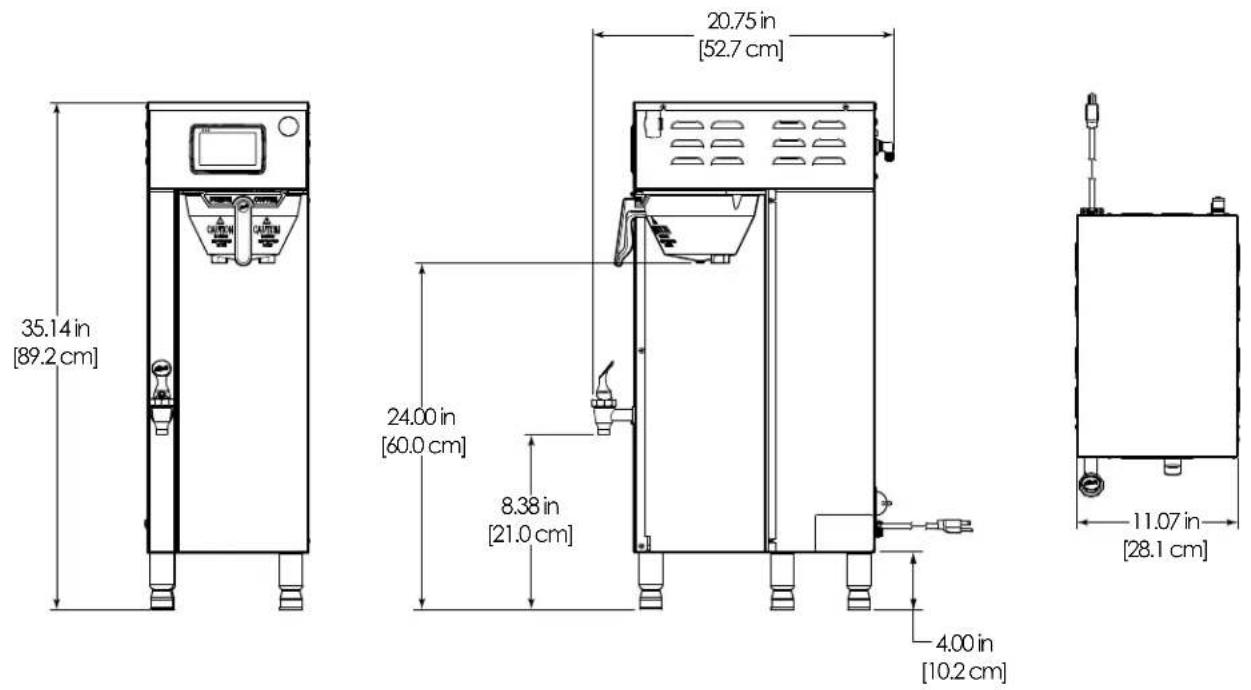
Dimensions
Water Supply Requirements
| MODEL # | HEIGHT | WIDTH | DEPTH | SHIP WEIGHT | SHIP CUBE | WATER CONNECTOR | WATER PRESSURE | MIN. FLOW RATE |
| G4TP2S10A3500 | 35.14" | 11.07" | 20.75" | 53.0 lbs | 9.6 cu ft | 3/8" flare | 20 - 90 psi | 1.0 gpm |
| G4TP2S63A3100 | 35.14" | 11.07" | 20.75" | 53.0 lbs | 9.6 cu ft | 3/8" flare | 20 - 90 psi | 1.0 gpm |
| G4TP2S63A3500 | 35.14" | 11.07" | 20.75" | 53.0 lbs | 9.6 cu ft | 3/8" flare | 20 - 90 psi | 1.0 gpm |
| G4TP2T10A3500 | 35.42" | 20.07" | 20.75" | 75.0 lbs | 14.1 cu ft | 3/8" flare | 20 - 90 psi | 2.0 gpm |
| G4TP2T10A3100 | 35.42" 20.07" | 20.75" | 75.0 lbs 14.1 cu ft | 3/8" flare | 20 - 90 psi | 2.0 gpm | ||
Export
| G4TP2S30A3100 | 35.14" | 11.07" | 20.75" | 53.0 lbs | 9.6 cu ft | 3/8" flare | 20 - 90 psi | 1.0 gpm |
| G4TP2T30A3100 | 35.42" | 20.07" | 20.75" | 75.0 lbs | 14.1 cu ft | 3/8" flare | 20 - 90 psi | 2.0 gpm |
Following are the factory default settings for the ThermoPro brewer:
• Brew Temperature = 200°F
• Water Bypass = On LARGE and MEDIUM brew only
- Brew Volume = Large-Medium-Small
• Energy Save Mode = Off
Symbols

This is the safety alert symbol. It is used to alert you to potential physical injury hazards. Obey all safety messages that follow this symbol to avoid possible injury or death.

DANGER - Indicates a hazardous situation which, if not avoided, will result in death or serious injury.

WARNING - Indicates a hazardous situation which, if not avoided, could result in death or serious injury.

CAUTION - Indicates a hazardous situation which, if not avoided, could result in minor or moderate injury.

NOTICE - Indicates a situation which, if not avoided, could result in property damage.

IMPORTANT - Provides information and tips for proper operation.

SANITATION REQUIREMENTS
Important Safeguards/Conventions

WARNING:
- Make sure that this appliance is installed and grounded according to the INSTALLATION INSTRUCTIONS by qualified personnel before attempting to use it. Failure to follow the INSTALLATION INSTRUCTIONS could result in personal injury or void the warranty.
- This appliance is designed for commercial use. Any service other than cleaning and preventive maintenance should be performed by an authorized Wilbur Curtis service technician.
- To reduce the risk of fire or electric shock, DO NOT open the service panels. There are no user serviceable parts inside.
- Keep hands, arms and other items away from hot surfaces of the unit during operation.
- Clean the appliance and any dispensers completely before using them for the first time as according to the CLEANING INSTRUCTIONS. Clean them regularly as instructed in the CLEANING INSTRUCTIONS.
- Use this appliance only for its intended use, brewing/dispensing hot and/or cold beverages/water.
- This appliance is not intended for use by persons (including children) with reduced physical, sensory or mental capabilities or lack of experience and knowledge, unless they have been given supervision or instruction concerning use of the appliance by a person responsible for their safety.
- Children should be supervised to ensure that they do not play with the appliance.
- Avoid spillage onto the power (mains) connector.
CE Requirements
- This appliance must be installed in locations where it can be overseen by trained personnel.
- For proper operation, this appliance must be installed where the temperature is between 5°C to 35°C.
- Appliance shall not be tilted more than 10° for safe operation.
- An electrician must provide electrical service as specified in conformance with all local and national codes. For safe use, an all-pole disconnection must be incorporated into the fixed wiring in accordance with the wiring rules outlined in clause 7.12.2 of IEC 6.335-1 for meeting the minimum electrical safety of this standard.
- This appliance must not be cleaned by water jet.
- This appliance can be used by persons aged from 18 years and above if they have been given supervision or instruction concerning use of the appliance in a safe way and if they understand the hazards involved.
- Keep the appliance and its cord out of reach of children aged less than 18 years.
- Appliances can be used by persons 18 years and above with reduced physical, sensory or mental capabilities or lack of experience and knowledge if they have been given supervision or instruction concerning use of the appliance in a safe way and understand the hazards involved.
• Children under the age of 18 years should be supervised to ensure they do not play with the appliance.
- If the power cord is ever damaged, it must be replaced by the manufacturer or authorized service personnel with a special cord available from the manufacturer or its authorized service personnel in order to avoid a hazard.
• Machine must not be immersed for cleaning.
- Cleaning and user maintenance shall not be made by children unless they are older than 18 years and supervised.
- This appliance is intended to be used in household and similar applications such as:
– staff kitchen areas in shops, offices and other working environments;
– by clients in hotels, motels and other residential type environments;
– bed and breakfast type environments.
- This appliance not intended to be used in applications such as:
- farm houses
- Access to the service areas permitted by Authorized Service personnel only.
• The A-Weighted sound pressure level is below 70 dBA.

WARNING: Installation is to be performed only by a qualified installer.

WARNING: Improper electrical connection may result in an electric shock hazard. This brewer must be properly grounded.

NOTICE: DO NOT connect this brewer to a hot water supply. The water inlet valve is not rated for hot water. Do not exceed the maximum water pressure stated in the SPECIFICATIONS section.

IMPORTANT: Observe all governing codes and ordinances.
Installation Instructions
Installation Requirements
- A secure surface capable of supporting the weight of the appliance.
- For units without an attached cord set: Appropriately sized, UL listed, grounding type power cable to meet the electrical specifications for the appliance. If you have questions about the correct cable size and length, consult a qualified installer. If the appliance will be hard wired to a junction box, the power cable must be long enough so that the unit can be moved for cleaning underneath.
- A grounded electrical connection to an electrical circuit that meets the electrical specifications of the appliance (see SPECIFICATIONS). The circuit must be protected by the appropriate sized circuit breaker. If you are not certain that the existing circuit meets the requirements for your unit, consult a licensed electrician.
- A water filtration system is required to maintain trouble-free operation. Wilbur Curtis Co., Inc. recommends a Wilbur Curtis approved water filter. Visit www.wilburcurtis.com to see the full line of Wilbur Curtis approved water filters.
- Potable water supply line connection from the water filter capable of supplying the minimum flow rate required by the specifications. The water supply line must be able to connect to the flare fitting on the back of the unit. See the SPECIFICATIONS section for the correct size. The water line should also be capable of being controlled by a shut off valve. Do not connect the water line to a saddle valve.

NSF International requires the following water connection:
1 A quick disconnect or additional coiled tubing (at least two times the depth of the appliance) is required so that it can be moved for cleaning underneath.
2 This equipment is to be installed with adequate back-flow protection to comply with applicable federal, state and local codes.
3 Water pipe connections and fixtures directly connected to a potable water supply shall be sized, installed and maintained in accordance with federal, state and local codes.
The International Plumbing Code of the International Code Council and the Food and Drug Administration (FDA) Food Code manual, direct that this equipment must be installed with adequate back-flow prevention in compliance with federal, state and local codes. For units installed outside of the U.S.A., make sure that the installation is in compliance with the applicable plumbing/sanitation code for your area.
Installation
Leveling

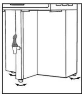
WARNING: Use the leveling legs to level the brewer only. Do not use them to adjust brewer height. Do not extend them higher than necessary.
1 Position the brewer on the counter top. Level it left to right and front to back by turning the bottom of the legs.
Connect the Water Supply
2 Flush the water supply line prior to installation to purge air and debris from the water filter and tubing.
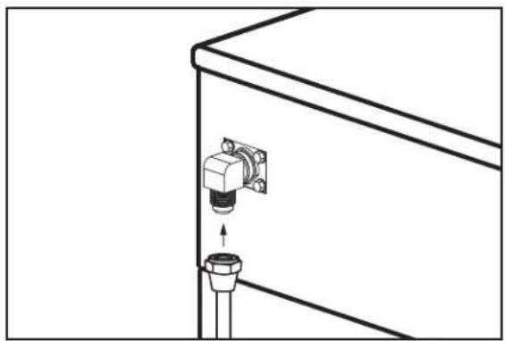
3 Connect the water supply line to the flare fitting on the back of the brewer. Leave the water supply valve closed until the power is connected.
Connect the Brewer Wiring
Brewers Without A Cord Set Attached and Dual Voltage Brewers to be Operated 220 Volts

WARNING: Turn off power to the junction box at the circuit breaker panel before connecting the power cable to the brewer.
4 Remove the screws that hold the front panel in place and remove.
5 On dual voltage units being operated at 220 Volts, disconnect and cap the jumper wire between the "C" and "N" terminals on the terminal block.
6 Loosen the strain relief on the back of the brewer.
7 Feed the 220 Volt power cable into the brewer.
8 Connect the wires on the power cable to the terminal block inside the brewer.
9 Tighten the strain relief and replace the front panel.
10 Connect the power cable wires to the terminals in the junction box. See the ELECTRICAL SCHEMATIC for the power supply requirements.


Connect the Brewer Wiring (cont.)
Brewers With A Cord Set Attached

WARNING: Connect the power cord to the appropriate type and size electrical outlet. If the electrical outlet is not compatible with the power cord, have it upgraded by a licensed electrician. Do not modify the power plug. Do not use an extension cord. Do not use a power cord/plug that is damaged.
11 Connect the power cord to the appropriate type of electrical outlet.
Power Up the Brewer
12 Turn on the water supply valve.
13 Make sure that the circuit breaker supplying power to the unit is on.
14 Turn the toggle switch on the back of the brewer to the ON position. The water tank will start to fill. While the tank is filling, inspect the water supply line for leaks.
15 Go to the PROGRAMMING GUIDE section and program the brewer for the correct model and batch number.

IMPORTANT: When operating the brewer at higher elevations, reduce the operating temperature by 2° F for each 1000 feet of elevation. See PROGRAMMING GUIDE.
16 When the water level in the tank rises to the correct volume, the heating elements will turn on automatically. Depending on the incoming water temperature and the electrical specifications, the water tank typically requires 20 to 30 minutes to reach the factory set operating temperature. When the water has heated, "Ready to Brew" should be on the display.
17 Before brewing for the first time, dispense 12 ounces of hot water through the hot water faucet to help purge air from the tubing inside the brewer.
18 Brew a cycle of at least 12 ounces, to purge any remaining air from the tubing. See OPERATING INSTRUCTIONS. During the initial brew cycle and whenever the filter is replaced, you may hear the sounds of air being purged from the filter, tubing and water tank.


Brewing Instructions

WARNING - TO AVOID SCALDING, AVOID SPLASHING. Keep body parts clear of the brewer during brewing. Do not remove the brew basket while "Brewing" appears on the display.
The G4 ThermoPro Brewer is factory preset for optimal performance.
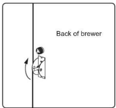
1 The brewer should be ON. Confirm this at the rear toggle switch. "Ready to brew" should be on the display. If the brewer is connected to an inter-lock grinder, the grinder should be on. When inter-lock connection is made, grind coffee at this time.
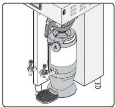
2 Center an empty dispenser under the brew basket.
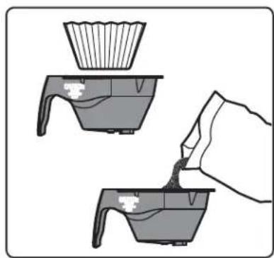
3 Insert a clean paper filter into the brew basket. Fill with the proper amount of ground coffee. Level the coffee in the filter.
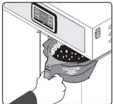
4 Slide the filled brew basket into the brew rails under the control panel. Slide it all the way back until it stops.

5 Hold your finger on the appropriate brew icon. As soon as you hear the click of the brew valve, lift your finger. Brewing will begin.
| 1 | 2 | 3 |
| 4 | 5 | 6 |
| 7 | 8 | 9 |
| Del | 0 | OK |
6 If a keypad appears on the display, the brew code feature is enabled (default is off). Brewing will start immediately after you enter the brew code. See the PROGRAMMING GUIDE to set up/disable the brew code.
The brewer will brew coffee based on the settings programmed into the universal control module (UCM). To change the settings, see the PROGRAMMING GUIDE section.

WARNING: HOT SURFACES - To avoid injury, allow the brewer and dispenser(s) to cool before cleaning.

NOTICE - Do not use cleaning liquids, compounds or powders containing chlorine (bleach) or corrosives. These products promote corrosion and will damage the finishes. USE OF THESE PRODUCTS WILL VOID THE WARRANTY.
Cleaning The Brewer - Daily

WARNING: DO NOT immerse the brewer in water or any other liquid.
The brewer should be OFF. Turn the brewer off by flipping the rear toggle switch to the OFF position.
1 Remove the dispenser(s). Wipe exterior brewer surfaces with a damp cloth to remove spills and debris.
2 Remove the brew basket(s) and clean them in a mild detergent solution. Use a soft bristled brush for hard to clean areas. Rinse with clean water, then dry.
3 Wipe the spray head area with a cloth soaked in a mild detergent solution. Rinse with a cloth soaked with clean water removing any residual detergent. Use a clean, soft cloth to dry.
4 Dump out the drip tray(s) (if applicable). Rinse with clean water, then dry with a soft, clean cloth.
Cleaning The Brewer - Weekly
The brewer should be OFF. Turn the brewer off by flipping the rear toggle switch to the OFF position.
1 Remove the spray head(s), unscrewing counterclockwise from the dome plate.
2 Thoroughly clean and rinse the dome plate area.
3 Clean the brew basket rails with a brush soaked with a mild detergent solution. Rinse the area with a cloth soaked with clean water, removing any residual detergent.
4 Dry the area with a soft, clean cloth.
5 Reattach the spray head(s).
Cleaning the 1.0 Gallon or 1.5 Gallon Thermal Dispensers (Daily)

WARNING: DO NOT immerse the thermal server or its lid assembly in water or any other liquid. Do not place the thermal server or lid in a dishwasher. Placing a thermal server in a dishwasher will void the warranty. To avoid damage, DO NOT use a brush to clean the faucet or the inside of the faucet shank (outlet).
Cleaning the Container
1 Prepare a mild solution of detergent and warm water. Remove the server from the brewer and remove the lid. Rinse.
2 Wash - Wipe the exterior surfaces of the container with a sponge soaked with the detergent solution to remove spills and debris. Remove the lid and fill the liner with the detergent solution. Take a sponge brush and scrub out the stainless steel liner and the lid.
3 Rinse - Rinse with clean, warm water.
4 Sanitize - Sanitize the interior of the server and the lid, using a commercial sanitizer suitable for food grade applications. Sanitize according to the directions on the package.
5 Disassemble the faucet - Unscrew the handle/bonnet assembly from the top of the faucet and remove it. Inspect the seat cup for wear. Replace the seat cup if it is damaged.
Disassemble the sight gauge (some versions). If the sight gauge has a cover, pull it up and off to remove. Remove the cap to disassemble the gauge (both versions). Some versions are equipped with a guard that must be unscrewed to access the lower washer and float. Remove the glass tube. Inspect it for cracks or chips. If broken, replace the glass with a new one.
6 Air Dry - Turn the container and lid upside down and allow to air dry.
Cleaning the Faucet Parts and Site Gauge
7 Wash - Wash all faucet and gauge glass parts with the detergent solution. Using the supplied brush, clean inside the fill tube on the lid. Clean the inside of the gauge glass with a gauge brush soaked with detergent solution.
8 Rinse - Thoroughly rinse all parts with clean, warm water.
continued....


CLEANING INSTRUCTIONS CI5
Cleaning the Faucet Parts and Gauge Glass (cont.)
9 Sanitize - After rinsing, place all faucet and gauge parts in a sink to be sanitized. Immerse them in a commercial sanitizer suitable for food grade applications. Sanitize according to the directions on the package.
10 Air Dry - Allow all parts to thoroughly air dry.
11 Reassemble - When dry, reassemble the handle/bonnet. Hand tighten the handle/bonnet onto the top of the faucet assembly, reinstall the site gauge and cover. If replacing a broken gauge glass, carefully remove any traces of glass from the silicone parts before inserting the new gauge glass tube. Reinstall the lid.

Cleaning the Airport/Pour Pot (Daily)

WARNING: DO NOT immerse the airport/pour pot or lid assembly in water or any other liquid. Do not place the airport/pour pot or lid in a dishwasher. Placing a airport or pour pot in a dishwasher will void the warranty.
Start by preparing a mild solution of detergent and warm water. Remove the airport/pour pot from the brewer and remove/open the lid. On airpots, remove the nozzle assembly. Rinse.
Cleaning Airpots
1 Wash - Wipe the exterior surfaces of the airport and lid with a sponge soaked with the detergent solution to remove spills and debris. Fill the liner with the detergent solution. Use a sponge cleaning brush to clean inside. Clean the spout/siphon tube with the detergent solution.
2 Rinse - Rinse the airport and the spout/siphon tube with clean, warm water.
3 Sanitize - Sanitize the interior of the airport, the spout/siphon tube and the lid, using a commercial sanitizer suitable for food grade applications. Swab, brush or pressure spray the sanitizing solution according to the directions on the package.
4 Air Dry - Turn the airport and lid upside down. Allow all parts to air dry.
Cleaning Pour Pots
1 Wash - Wipe the exterior surfaces of the pour pot and lid with a sponge soaked with the detergent solution to remove spills and debris. Fill the liner with the detergent solution. Use a sponge cleaning brush to clean inside.
2 Rinse - Rinse the pour pot and the lid with clean, warm water.
3 Sanitize - Sanitize the interior of the pour pot and the lid, using a commercial sanitizer suitable for food grade applications. Swab, brush or pressure spray the sanitizing solution according to the directions on the package.
4 Air Dry - Turn the pour pot and lid upside down and allow to air dry.
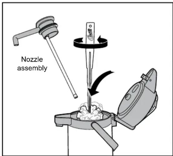
TLXA2201G000 shown. Appearance and size varies with model number.

CLXP6401S100 shown. Appearance and size varies with model number.

NOTE: The stem on the bottom of TFT series pour pot lids have a built-in sensor used for the FreshTrac feature. Keep this stem free from coffee oil build-up for proper operation. After cleaning, inverting the lid for 30 seconds resets the FreshTrac timer.
Touchscreen Control Module
The touchscreen turns on whenever power is provided to the brewer and the rear toggle switch is on. The symbol buttons on the screen control operation and programming. Pressing the on-screen symbols and buttons with your finger tip activates the various functions. The default screen, as well as additional control buttons are shown below. The configuration of the default screen varies depending on the brewer model.

Entering Programming Mode
1 Tap the (white) Curtis logo on the touchscreen five (5) times to enter programming mode (see diagram above).
| ENTER ACCESS CODE | ||
| 1234 | ||
| 1 | 2 | 3 |
| 4 | 5 | 6 |
| 7 | 8 | 9 |
| Del | 0 | OK |
2 The ACCESS CODE screen will appear. The default pass code is 1 2 3 4. Once the code is entered, press OK. The MAIN MENU screen will appear. The access code can be reset in the Control Settings sub-menu, under Passwords.

3 The MAIN MENU screen contains a series of sub-menu icons. The icons vary based on the model selected under the Model Select sub-menu. For the brewer to operate properly, the model selected must match the model series on the brewer model number label affixed to the outside of the machine.
Programming
Shown below are the various programming options available in the programming MAIN MENU. The icons that appear vary based on the brewer model selected under Model Select.
![graph TD A["Model Select"] --> B["Selections for COFFEE BREWER MODELS"] B --> C["Recipes"] C --> D["Control Settings: Brew Settings"] D --> E["Settings Summary"] E --> F["Exit"] G["Coffee"] --> H["Gemini\nGemini IF\nThermoPro\nMilano\nOmega"] H --> I["Single Twin"] I --> J["One Batch\nTwo Batch\nThr…](/content/2026/05/1060457/images/646349707ede65d67291e8686a412f2fcf654de8c6705d3c08fae6a2710a7391.jpg)
![graph TD A["Model Select"] --> B["TEA"] B --> C["Tea/IC-1Bach\nTea/IC-2Bach\nTea/IC-3Bach\nTea/IC-4Bach\nTea-Sweet\nDual-Dilution\nDual-Sweet"] C --> D["Tea/Brewer Models"] D --> E["Recipes"] E --> F["Control Settings Brew Settings"] F --> G["Settings Summary"] G --> H["Exit"] E --> I["Standard-Purp…](/content/2026/05/1060457/images/12bb0e273542d9fe33426d36fe9e1c65ea262524fc8c6ac586b99e982b06c192.jpg)
![graph TD A["Model Select"] --> B["Selections for COMBO BREWER MODELS"] B --> C["Tea Recipes"] C --> D["Coffee Recipes"] D --> E["Control Settings"] E --> F["Tea Brew Settings"] F --> G["Coffee Brew Settings"] G --> H["Settings Summary"] H --> I["Exit"] J["Combo"] --> K["Combo Combo/IC Combo-Sweet"]…](/content/2026/05/1060457/images/8612618c2f4f15e24370b7b5061f1b7bec9029edf16b2fc805f07c57813eae42.jpg)
* Feature not available on some models
USB - Easy Programming
There are two methods for changing the default settings on G4 brewers. The settings can be programmed manually using the brewer touch screen, or automatically using the USB (Universal Serial Bus) data port on the side of the brewer. Using the USB connection and a flash drive easily reprograms the settings by simply copying data.

A flash drive can copy all of the settings from one identical G4 brewer to another. Doing so eliminates the need to program each step individually using the touchscreen. This process also makes it easy to quickly standardize the program settings on multiple G4 brewers.
Use a flash drive that supports USB 2.0 or above and has a type-A USB connection. The storage capacity must be 2 GB minimum.

IMPORTANT: The flash drive must be completely blank. Erase any existing files on the drive before starting the following process.
Uploading the Software to the Flash Drive
1 Make sure the brewer is on. Check to make sure that the brewer you are copying settings from is programmed as desired.
2 Open the cover on the USB port and insert the connector on the empty flash drive. The port is located on the right side panel of the brewer, near the top. The universal control module (UCM) will upload all of the setup data onto the flash drive. The yellow LED icon on the top left of the touchscreen will light indicating that data is transferring. This process will only take a second to complete.
Downloading the Software to the Brewer from the Flash Drive
1 Select the (identical) brewer you wish to make program changes to. The brewer must be on.
2 Plug the loaded flash drive into the USB port on the brewer. The data copied from the first brewer will automatically download, overwriting all the settings that were on the second brewer.
3 The red LED on the top left of the touchscreen will indicate that the download is in process. This will only take a second.
4 Once the download is complete, the UCM will reboot so that the changes take effect.
5 Remove the flash drive. The download is complete. The data on the flash drive can continue to be downloaded into as many identical brewers as needed.
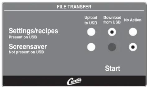
USB File Transfer
This screen will be present whenever the USB flash drive is inserted, provided the brewer is not currently brewing.
The default action is "No Action". The UCM will always create a backup on the flash drive before downloading settings/recipes or a screen-saver.
If a firmware update is present on the flash drive, the firmware update procedure will be started before the screen is shown.
G4TP2S - Single Coffee Brewer
G4TP2T - Twin Coffee Brewer

Supplies and Accessories - All Models


CAB-1 - Cleaning BrushWC-29050 - Spray Head
G4TP2S - Main Chassis - Exploded View
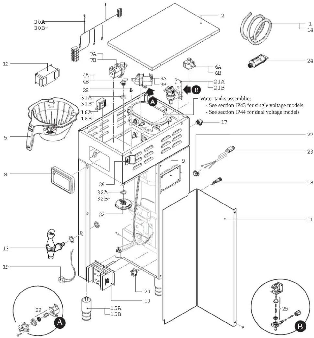
G4TP2S - Main Chassis - Parts List
| ITEM # | PART # | DESCRIPTION |
| 1 WC | -5350 TUBE, 1/2 ID | x 1/8W SILICONE GEN USE |
| 2 WC | -61509 COVER, TOP | TP2S |
| 3A WC | -37122 1 | KIT, DUMP VALVE RIGHT |
| 3B WC | -854 2 | VALVE, BREW DUMP RIGHT 240V 12W GEM12D/TP/TPC |
| 4A WC | -2977K a | KIT, SPRAYHEAD FITTING METAL |
| 4B WC | -2977-101K b | KIT, SPRAYHEAD FITTING PLASTIC |
| 5 WC | -3417 | BREW CONE, ASSY W/SPLASH POCKET BRWNSTYLIZED GEMIN HOT COFFEE |
| 6A WC | -442 1 | SOLENOID, LOCK BREW CONE RIGHT/LEFT120V TP2T/TP2S/GEMSS/GEM |
| 6B WC | -446 2 | SOLENOID, LOCK BREW CONE RIGHT 220VTHERMOPRO/GEMTS |
| 7A WC | -844-101 1 | VALVE, BY-PASS. NON-ADJUSTABLE WITHRESTRICTOR (WC-2945) |
| 7B WC | -844-102 2 | VALVE, BY-PASS. 240V NON-ADJUSTABLE W/RESTRICTOR (WC-2945) |
| 8 WC | -10000 CONTROL MODULE, TOUCH SCREEN G4 | |
| 9 WC | -10001 CONTROL MODULE, UPM 120/220V G4 | |
| 10 WC | -8559 | RELAY, SOLID STATE 280V/40A W/HEATSINKAND QUICK DISCONNECTS |
| 11 WC | -58037-101 COVER, CENTER WRAP TP 90 DEG | |
| 12 WC | -596 2 | FILTER, NOISE EMI 250VAC/30A 1PH |
| 13 WC | -1825 FAUCET, ASSY HOT WATER TP2S | |
| 14 WC | -5310 TUBE, 5/16 ID x 1/8W SILICONE | |
| 15A WC | -3528 1 | LEG, 4" ADJUSTABLE 3/8-16 THRD ITALIANSTYLE |
| 15B WC | -3500T 2 | LEG, 4" ADJUSTABLE W/TIE DOWNS 3/8-16THRD |
| 16A WC | -589-101 1 | TRANSFORMER,120VAC-24V 4.8A W/ LEADS &MOLEX CONNECTOR |
| 16B WC | -589-102 2 | TRANSFORMER,240VAC- 24V 4.8VA W/LEADS &MOLEX CONNECTOR |
1 G4TP2S10A3500, G4TP2S63A3100, G4TP2S63A3500, 2 G4TP2S30A3100
a Units built 05/15/17 and later. Stainless steel fitting kit (4A) is compatible with older units.
b Units built before 05/15/17.
G4TP2S - Recommended Parts to Stock
| ITEM # | PART # DESCRIPTION |
| 1 WC | -5350 TUBE, 1/2 ID x 1/8W SILICONE GEN USE |
| 3A WC | -37122 KIT, DUMP VALVE RIGHT |
| 6A WC | -442 SOLENOID, LOCK BREW CONE RIGHT/LEFT 120V TP2T/TP2S/GEMSS/GEM |
| 7A WC | -844-101 VALVE, BY-PASS, NON-ADJUSTABLE WITH RESTRICTOR (WC-2945) |
| 9 WC | -10001 CONTROL MODULE, UPM 120/220V G4 |
| ITEM # | PART # | DESCRIPTION |
| 17 WC-2402P ELBOW, 3/8"FL x 3/8" NPT PLATED | ||
| 18 WC-1501 FUSE, HOLDER ASSY W/5A FUSE | ||
| 19 WC-14045-101 CURRENT SENSOR ASSY G4 | ||
| 20 WC-103 | SWITCH, TOGGLE NON-LIT DPST 25A125/250VAC RESISTIVE | |
| 21A WC-847 1 | VALVE, INLET 2 GPM 120V 10W GEN USEBROWN BODY | |
| 21B WC-883 2 | VALVE, INLET 2 GPM 240V 6W | |
| 22 WC-29050 SPRAYHEAD, AMBER ADVANCED FLOW | ||
| 23 WC-1200 CORD, 14/3 $JTO 6' BLK W/PLUG | ||
| 24 WC-5231 COMPOUND. SILICONE 5OZ | ||
| 25 WC-3765L | KIT, INLET VALVE REPAIR USE ON WC-826/WC-826L/WC-847 (OLDER UNITS) | |
| 26 WC-10008 UNIVERSAL HOST ADAPTER USB | ||
| 27 WC-1412 CORD GRIP, 3/4" FOR METAL CORD TO .81"OD | ||
| 28 WC-29044 SLEEVE, OVERFLOW ASSY GEN USE | ||
| 29 WC-37132 | KIT, VALVE REPAIR FOR INVENSYS WC-820WDR,WC-821WDR, WC-844WDR (OLDERUNITS) | |
| 30A WC-13462 1 | HARNESS ASSY G4TP2S | |
| 30B WC-13462-101 2 | HARNESS, COMPLETE G4TP2S30'S EXPORTVERSION (INCLUDES TERMINAL BLOCK) | |
| 31A WC-4320 a | O'RING, 0.487I.D.x 0.693OD x0.103CS BUNA-N#112 | |
| 31B WC-43089 b | GASKET, 1.00OD X .625 I.D. X .030 THK WHITEEPDM 70 SHORE | |
| 32A WC-4213 a | NUT, 5/8 LOCK PLATED | |
| 32B WC-4212-02 b | NUT, 5/8-18 JAM PLASTIC | |
| ITEM # | PART # | DESCRIPTION |
| 14 | WC-5310 TUBE, 5/16 ID x 1/8W SILICONE | |
| 19 | WC-14045-101 CURRENT SENSOR ASSY G4 | |
| 21A | WC-847 | VALVE, INLET 2 GPM 120V 10W GEN USE BROWN BODY |
| 22 | WC-29050 SPRAYHEAD, AMBER ADVANCED FLOW | |
G4TP2T - Main Chassis - Exploded View
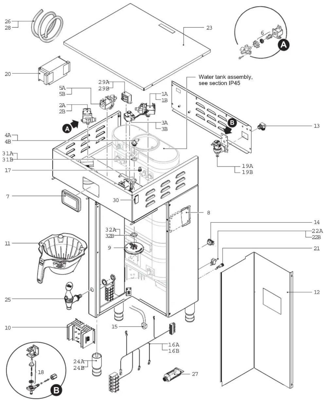
G4TP2T - Main Chassis - Parts List
| ITEM # PART # DESCRIPTION | ||
| 1A WC-37122 | 1 | KIT, DUMP VALVE RIGHT |
| 1B WC-854 | 2 | VALVE, BREW DUMP RIGHT 240V 12W GEM12D/TP/TPC |
| 2A WC-37121 | 1 | KIT, DUMP VALVE LEFT |
| 2B WC-853 | 2 | VALVE, BREW DUMP LEFT 240V 12W GEM12D/TP/TPC |
| 3A WC-442 | 1 | SOLENOID, LOCK BREW CONE RIGHT/LEFT 120V TP2T/TP2S/GEMSS/GEM |
| 3B WC-446 | 2 | SOLENOID, LOCK BREW CONE RIGHT 220V THERMOPRO/GEMTS |
| 4A WC-2977K | a | KIT, SPRAYHEAD FITTING METAL |
| 4B WC-2977-101K | b | KIT, SPRAYHEAD FITTING PLASTIC |
| 5A WC-844-101 | 1 | VALVE, BY-PASS, NON-ADJUSTABLE WITH RESTRICTOR (WC-2945) |
| 5B WC-844-102 | 2 | VALVE, BY-PASS, 240V NON-ADJUSTABLE W/RESTRICTOR (WC-2945) |
| 6 WC-37132 | KIT, VALVE REPAIR FOR INVENSYS WC-820WDR,WC-821WDR, WC-844WDR | |
| 7 WC-10000 CONTROL M | DULE, TOUCH SCREEN G4 | |
| 8 WC-10001 CONTROL M | DULE, UPM 120/220V G4 | |
| 9 WC-29050 SPRAYHEAD, | AMBER ADVANCED FLOW | |
| 10 WC-8559 | RELAY, SOLID STATE 280V/40A W/ HEATSINK AND QUICK DISCONNECTS | |
| 11 WC-3417 | BREW CONE, ASSY W/SPLASH POCKET BRWN STYLIZED GEMIN HOT COFFEE | |
| 12 WC-58037-101 COVER, | CENTER WRAP TP 90 DEG | |
| 13 WC-2402P ELBOW, 3/8" | L x 3/8" NPT PLATED | |
| 14 WC-1412 CORD GRIP, 3/4" FOR METAL CORD TO .81"OD | ||
| 15 WC-14045-101 CURRENT | SENSOR ASSY G4 | |
| 16A WC-13450 | 1 | HARNESS ASSY, COMPLETE G4TP2T (INCLUDES TERMINAL BLOCK) |
| 16B WC-13450-101 | 2 | HARNESS ASSY COMPLETE G4TP2T G4TPC2T/G4GEMT/G4TP1T-30'S (INCLUDES TERMINAL BLOCK) |
1 G4TP2T10A3100, G4TP2T10A3500, 2 G4TP2T30A3100
a Units built 05/15/17 and later. Stainless steel fitting kit (4A) is compatible with older units.
b Units built before 05/15/17.
G4TP2T - Recommended Parts to Stock
| ITEM # PART # DESCRIPTION | ||
| 1A WC- | 37122 KIT, DUMP VALVE RIGHT | |
| 2A WC- | 37121 KIT, DUMP VALVE LEFT | |
| 3A WC- | 442 | SOLENOID, LOCK BREW CONE RIGHT/LEFT 120V TP2T/TP2S/GEMSS/GEM |
| 5A WC- | 844-101 | VALVE, BY-PASS, NON-ADJUSTABLE WITH RESTRICTOR (WC-2945) |
| 8 WC-1 | 10001 CONTROL MODULE, UPM 120/220V G4 | |
| ITEM # PART # DESCRIPTION | ||
| 17 WC-29044 SLEEVE, OVERFLOW ASSY GEN USE | ||
| 18 WC-3765L | KIT, INLET VALVE REPAIR USE ON WC-826/WC-826L/WC-847 (OLDER UNITS) | |
| 19A WC-847 1 | VALVE, INLET 2 GPM 120V 10W GEN USE BROWN BODY | |
| 19B WC-883 2 | VALVE, INLET 2 GPM 240V 6W | |
| 20 WC-596 2 | FILTER, NOISE EMI 250VAC/30A 1PH | |
| 21 WC-1501 FUSE, HOLDER ASSY W/5A FUSE | ||
| 22A WC-102 1 | SWITCH, TOGGLE NON-LIT SPST 15A 125/6A 250VAC RESISTIVE | |
| 22B WC-103 2 | SWITCH, TOGGLE NON-LIT DPST 25A 125/250VAC RESISTIVE | |
| 23 WC-5459 COVER, TOP SS THERMOPRO | ||
| 24A WC-3528 1 | LEG, 4" ADJUSTABLE 3/8-16 THRD ITALIAN STYLE | |
| 24B WC-3500T 2 | LEG, 4" ADJUSTABLE W/TIE DOWNS 3/8-16 THRD | |
| 25 WC-1825 FAUCET, ASSY HOT WATER TP2S | ||
| 26 WC-5310 TUBE, 5/16 ID x 1/8W SILICONE GEN USE | ||
| 27 WC-5231 COMPOUND, SILICONE 5 OZ | ||
| 28 WC-5350 TUBE, 1/2 ID x 1/8W SILICONE GEN USE | ||
| 29A 1 | WC-589-101 | TRANSFORMER,120VAC-24V 4.8A W/ LEADS & MOLEX CONNECTOR |
| 29B 2 | WC-589-102 | TRANSFORMER,240VAC- 24V 4.8VA W/LEADS & MOLEX CONNECTOR |
| 30 WC-10008 UNIVERSAL HOST ADAPTER USB | ||
| 31A WC-4320 a | O'RING, 0.487I.D.x 0.693OD x0.103CS BUNA-N #112 | |
| 31B WC-43089 b | GASKET, 1.00OD X .625 I.D. X .030 THK WHITE EPDM 70 SHORE | |
| 32A WC-4213 a | NUT, 5/8 LOCK PLATED | |
| 32B WC-4212-02 b | NUT, 5/8-18 JAM PLASTIC | |
| ITEM # PART # DESCRIPTION | |
| 9 WC-29050 SPRAYHEAD, AMBER ADVANCED FLOW | |
| 15 WC-14045-101 | CURRENT SENSOR ASSY G4 |
| 19A WC-847 | VALVE, INLET 2 GPM 120V 10W GEN USE BROWN BODY |
| 26 WC-5310 | TUBE, 5/16 ID x 1/8W SILICONE GEN USE |
| 28 WC-5350 | TUBE, 1/2 ID x 1/8W SILICONE GEN USE |
WC-62032 - Tank Assembly
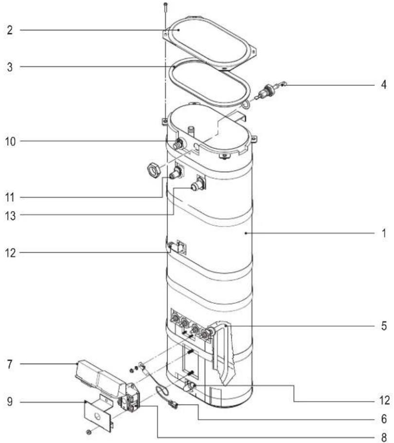
WC-62032 - Tank Assembly - Parts List
| ITEM # PART # DESCRIPTION | |
| 1 WC-62032 TANK, COMPLETE TP2S ULTEM FITTINGS | |
| 2 WC-5853-102 COVER, TOP HEATING TANK GEN USE | |
| 3 WC-43062 GASKET, TANK LID | |
| 4 WC-5527K KIT, PROBE WATER LEVEL O-RING & NUT | |
| 5 WC-906-04 | KIT, ELEMENT, HEATING 2KW 220V W/ JAM NUT& SILICONE O-RING |
| 6 WC-1438-101 SENSOR, TEMPERATURE TANK | |
| 7 WC-4394 | GUARD, SHOCK/HEATING ELEMENT FOR SINGLE HEATING ELEMENT |
| ITEM # PART # DESCRIPTION | |
| 8 WC-522 | THERMOSTAT, HI LIMIT HEATER CONTROL DPST 277V 40A |
| 9 WC-43055 GUARD, SHOCK RESET THERMOSTAT (WC-522) | |
| 10 WC-37266 KIT, FITTING TANK OVERFLOW | |
| 11 WC-37317 | KIT, STRAIGHT FITTING & BUSHING 8mm GEN USE |
| 12 WC-37365 KIT, FITTING TANK INLET | |
| 13 WC-37357 | KIT, STRAIGHT PLASTIC FITTING AND BUSHING 12MM |
WC-62032 - Recommended Parts to Stock
| ITEM # PART # DESCRIPTION | |
| 3 WC-43062 GASKET, TANK LID | |
| 4 WC-5527K KIT, PROBE | WATER LEVEL O-RING & NUT |
| 6 WC-1438-101 SENSOR | TEMPERATURE TANK |
| 7 WC-4394 | GUARD, SHOCK/HEATING ELEMENT FOR SIN-GLE HEATING ELEMENT |
| 8 WC-522 | THERMOSTAT, HI LIMIT HEATER CONTROL DPST 277V 40A |
| ITEM # PART # DESCRIPTION | |
| 9 WC-43055 GUARD, SHOCK RESET THERMOSTAT (WC-522) | |
| 10 WC-37266 KIT, FITTING TANK OVERFLOW | |
| 11 WC-37317 | KIT, STRAIGHT FITTING & BUSHNG 8mm GEN USE |
| 12 WC-37365 KIT, FITTING TANK INLET | |
| 13 WC-37357 | KIT, STRAIGHT PLASTIC FITTING AND BUSHING 12MM |
WC-62031 - Tank Assembly
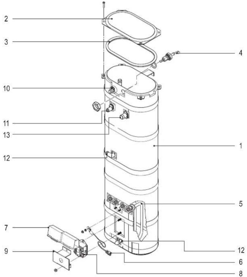
WC-62031 - Tank Assembly - Parts List
| ITEM # PART # DESCRIPTION | |
| 1 WC-62032 TANK, COMPLETE TP2S ULTEM FITTINGS | |
| 2 WC-5853-102 COVER, TOP HEATING TANK GEN USE | |
| 3 WC-43062 GASKET, TANK LID | |
| 4 WC-5527K KIT, PROBE WATER LEVEL O-RING & NUT | |
| 5 WC-904-04 | KIT, ELEMENT, HEATING 1.6KW120V W/ JAM NUT & SILICONE O-RING |
| 6 WC-1438-101 SENSOR, TEMPERATURE TANK | |
| 7 WC-4394 | GUARD, SHOCK/HEATING ELEMENT FOR SINGLE HEATING ELEMENT |
WC-62031 - Recommended Parts to Stock
| ITEM # PART # DESCRIPTION | |
| 3 WC-43062 GASKET, TANK LID | |
| 4 WC-5527K KIT, PROBE | WATER LEVEL O-RING & NUT |
| 6 WC-1438-101 SENSOR | TEMPERATURE TANK |
| 7 WC-4394 | GUARD, SHOCK/HEATING ELEMENT FOR SIN-GLE HEATING ELEMENT |
| 8 WC-522 | THERMOSTAT, HI LIMIT HEATER CONTROL DPST 277V 40A |
| ITEM # PART # DESCRIPTION | ||
| 8 WC-522 | THERMOSTAT, HI LIMIT HEATER CONTROL DPST 277V 40A | |
| 9 WC-43055 GUARD, SHOCK RESET THERMOSTAT (WC-522) | ||
| 10 WC-37266 KIT, FITTING TANK OVERFLOW | ||
| 11 WC-37317 | KIT, STRAIGHT FITTING & BUSHING 8mm GEN USE | |
| 12 WC-37365 KIT, FITTING TANK INLET | ||
| 13 WC-37357 | KIT, STRAIGHT PLASTIC FITTING AND BUSHING 12MM | |
| ITEM # PART # DESCRIPTION | |
| 9 WC-43055 GUARD, SHOCK RESET THERMOSTAT (WC-522) | |
| 10 WC-37266 KIT, FITTING TANK OVERFLOW | |
| 11 WC-37317 | KIT, STRAIGHT FITTING & BUSHNG 8mm GEN USE |
| 12 WC-37365 KIT, FITTING TANK INLET | |
| 13 WC-37357 | KIT, STRAIGHT PLASTIC FITTING AND BUSHING 12MM |
WC-62030 - Tank Assembly

WC-62030 - Tank Assembly - Parts List
| ITEM # PART # DESCRIPTION | |
| 1 WC-62030 TANK, COMPLETE TP2T ULTEM FITTINGS | |
| 2 WC-37008 KIT, TANK LID ROUND (INCLUDES GASKET) | |
| 3 WC-37357 | KIT, STRAIGHT PLASTIC FITTING AND BUSHING 12MM |
| 4 WC-5527K KIT, PROBE WATER LEVEL O-RING & NUT | |
| 5 WC-934-04 | KIT,ELEMENT HEATING 2.5KW 220V W/ JAM NUT & SILICONE WASHERS |
| 6 WC-1438-101 SENSOR, TEMPERATURE TANK | |
WC-62030 - Recommended Parts to Stock
| ITEM # PART # DESCRIPTION | |
| 2 WC-37008 KIT, TANK L | D ROUND (INCLUDES GASKET) |
| 3 WC-37357 | KIT, STRAIGHT PLASTIC FITTING AND BUSHING 12MM |
| 4 WC-5527K KIT, PROBE | WATER LEVEL O-RING & NUT |
| 5 WC-934-04 | KIT, ELEMENT HEATING 2.5KW 220V W/ JAM NUT & SILICONE WASHERS |
| 6 WC-1438-101 SENSOR | TEMPERATURE TANK |
| ITEM # PART # DESCRIPTION | |
| 7 WC-4382 GUARD, SHOCK HTNG ELMNT DOUBLE | |
| 8 WC-522 | THERMOSTAT, HI LIMIT HEATER CONTROL DPST 277V 40A |
| 9 WC-37365 KIT, FITTING TANK INLET | |
| 10 WC-37266 KIT, FITTING TANK OVERFLOW | |
| 11 WC-37317 KIT, STRAIGHT FITTING & BUSHNG 8MM GEN USE | |
| 12 WC-43055 GUARD, SHOCK RESET THERMOSTAT (WC-522) | |
| ITEM # PART # DESCRIPTION | |
| 8 WC-522 | THERMOSTAT, HI LIMIT HEATER CONTROL DPST 277V 40A |
| 9 WC-37365 KIT, FITTING TANK INLET | |
| 10 WC-37266 KIT, FITTING TANK OVERFLOW | |
| 11 WC-37317 KIT, STRAIGHT FITTING & BUSHNG 8MM GEN USE | |
| 12 WC-43055 GUARD, SHOCK RESET THERMOSTAT (WC-522) | |
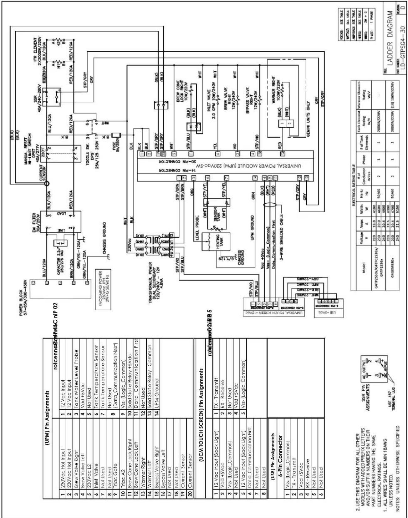
G4TP2S10A3500

G4GEMS63A1000, G4TP1S63A3100, G4TP2S63A3100, G4TP2S63A3500

| (UPM) Pin Assignments | |||
| rotcen | |||
| 1 | 12Vac Hot Input | 1 | 12 Vac Input |
| 2 | 120Vac Hot Input | 2 | 12 Vac Input |
| 3 | Brew Valve Right | 3 | Tank Water Level Probs |
| 4 | Brew Valve Left | 4 | Vad +5Vac |
| 5 | 120Vac Neutral | 5 | Not Used |
| 6 | Inlet Valve | 6 | Tank Temperature Sensor |
| 7 | Not Used | 7 | Tank Temperature Sensor |
| 8 | Not Used | 8 | [Not Used]Data_Communication Next |
| 9 | Triac Gate | ||
| 10 | Triac A2 | 9 | Vas- [Logic Common] |
| 11 | Brew Cone Lock Right | 10 | Solid State Relay +5Vac |
| 12 | Brew Cone Lock Left | 11 | Data Communication First |
| 13 | Warmer Right | 12 | Not Used |
| 14 | Warmer Left | 13 | Solid State Relay - Common |
| 15 | Bypass Valve Right | 14 | UPM Ground |
| 16 | Bypass Valve Left | ||
| 17 | Not Used | ||
| 18 | Not Used | ||
| 19 | Current Sensor | ||
| 20 | Current Sensor | ||
| (UCM TOUCH SCREEN) Pin Assignments | |||
| rotcen | |||
| 1 | 12 Vac Inout [Back Light] | 1 | TX - Transmit |
| 2 | Vdo +5Vac | 2 | RX -Receive |
| 3 | Vis- [Logic_Common] | 3 | Not Used |
| 4 | Not Used | 4 | Vad +5Vac |
| 5 | 12 Vac Input [Back Light] | 5 | Vas- [Logic Common] |
| 6 | Data_Communication First | ||
| 7 | Not Used | ||
| 8 | Not Used | ||
| (USB) Pin Assignments | |||
| 6-Pin Connector | |||
| 1 | Vss- [Logic_Common] | ||
| 2 | TX Transmit | ||
| 3 | Vdo +5Vac | ||
| 4 | RX -Receive | ||
| 5 | Not Used | ||
| 6 | Not Used | ||
| ELECTRICAL RATING TABLE | |||||||||
| Model | Voltage V | Amps A | Watts W | Hertz Hz | α /2 of Cunductor Wires | Phase | α /2 of Tank Elements | Tank Element Rating W/V | Warmer Element Rating W/V |
| (G4)GEM552 | 120 9.2 | 100 | (2) 50/60-3 (2) | 1/1 | 2 | 1150V/120V | (1X) 100W/120V | ||
| 110/220 | 9.5 2100 | ||||||||
| 120 9.2 | 100 | ||||||||
| 120/240 | 10 | 2400 | 3 | ||||||
| (G4)GEM563 | 120 | 15 | 1800 | 50/60 | (2) | 1 | 2 | 1600W/120V | (1X) 100W/120V |
| 110/220 | 12.7 | 3300 | 3 | ||||||
| 120 | 15 | 1800 | (2) | 1 | |||||
| 120/240 | 15 | 3600 | 3 | ||||||
| (G4)TP2552(G4)TPC2552 | 120 12.5 | 1300 | (2) 50/60-2 (2) | 1/1 | 2 | 1450W/120V | - | ||
| 110/220 | 13.2 | 2900 | 3 | ||||||
| 120 12.5 | 1500 | ||||||||
| 120/240 | 12.9 | 3100 | 3 | ||||||
| (G4)TP2563(G4)TPC2563 | 120 | 15 | 1800 | 50/60 | (2) | 1 | 2 | 1000W/120V | - |
| 110/220 | 12.7 | 2800 | 3 | ||||||
| 120 | 15 | 1800 | (2) | 1 | |||||
| 120/240 | 13.8 | 3300 | 3 | ||||||
| (G4)IP1552 | 120 12.5 | 1500 | (2) 50/60-2 (2) | 1/1 | 2 | 1450W/120V | - | ||
| 110/220 | 13.2 | 2900 | 3 | ||||||
| 120 12.5 | 1500 | ||||||||
| 120/240 | 12.9 | 3100 | 3 | ||||||
| (G4)TP1563 | 120 13.8 | 1650 | (2) 50/60-2 (2) | 1/1 | 2 | 1600W/120V | - | ||
| 110/220 | 12.2 | 2700 | 3 | ||||||
| 120 13.8 | 1650 | ||||||||
| 120/240 | 12.1 | 2900 | 3 | ||||||
| VOLUME | SET TABLE | TITLE: LADDER DIAGRAM | |
| WIND | SET TABLE | ||
| APPROVED | SET TABLE | ||
| RISK | SET TABLE | PART NUMBER: LD-GTPSG4-63 | REVISION: L |
| RISK | 20/3M + 0 | ||
| PAGE | 1 PAGE | ||
③ 12GA WHITE WIRE IS ONLY USED WHEN UNIT IS TO BE WIRED IN THE 120Vac
② USE THIS DIAGRAM FOR ALL OTHER MODELS WITH ADDED PREFIX LETTERS AND/OR SUFFIX NUMBERS ON THEIR PART NUMBERS HAVING
THE SAME ELECTRICAL RATINGS.
1. ALL WIRES SHALL BE 18AWG UNLES NOTES: UNLESS OTHERWISE SPECIFIED
G4GEMT10A1000, G4TP1T10A3100, G4TP2T10A3100, G4TP2T10A3500
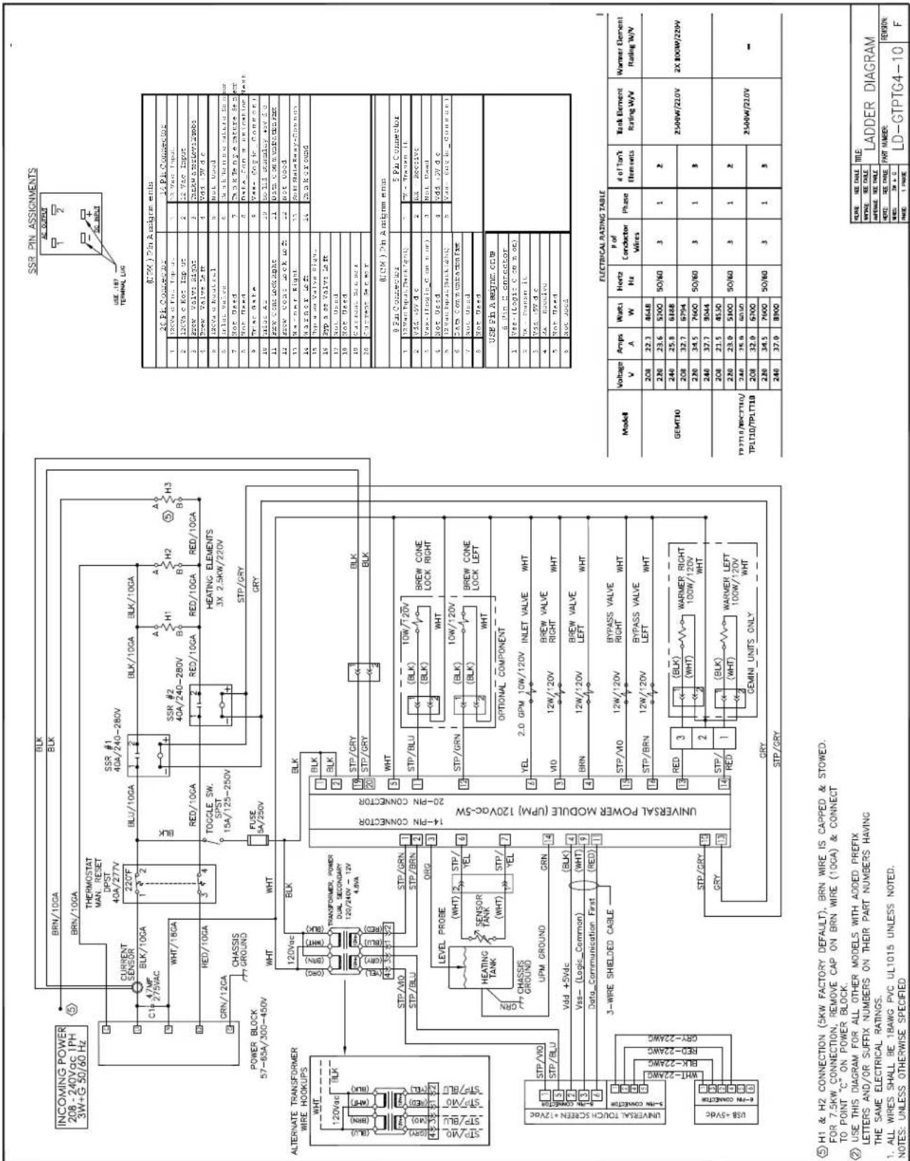
| ELECTRICAL RATING TABLE | |||||||||
| Model | Voltage V | Amps A | Watts W | Hertz Hz | P of Conductor Wires | Phase | # of Tank Elements | Tank Element Rating W/V | Warner Element Rating W/V |
| GEMT10 | 208 | 22.3 | 4648 | 50/60 | 3 | 1 | 2 | 2500W/220V | 2X 800W/220V |
| 220 | 23.6 | 5200 | |||||||
| 240 | 25.8 | 6188 | |||||||
| 208 | 32.7 | 6794 | 50/60 | 3 | 1 | 3 | |||
| 220 | 34.5 | 7600 | |||||||
| 240 | 37.7 | 8044 | |||||||
| TPLT10/TBC7T10/TPLT10/TPLTT10 | 208 | 21.5 | 4530 | 50/60 | 3 | 1 | 2 | 2500W/220V | - |
| 220 | 23.0 | 5100 | |||||||
| 240 | 25.0 | 6050 | |||||||
| 208 | 32.0 | 5700 | 50/60 | 3 | 1 | 3 | |||
| 220 | 34.5 | 7600 | |||||||
| 240 | 37.0 | 8000 | |||||||
| NOTE: | SEE DAILY | TITLE:LADDER DIAGRAM | |
| NOTE: | SEE DAILY | ||
| APPERME: | SEE DAILY | ||
| PART NUMBER:LD-GTPTG4-10 | REVISION:F | ||
| WHES: | 3W + 0 | ||
| PAGE: | 1 PAGE | ||
⑤ H1 & H2 CONNECTION (5KW FACTORY DEFAULT), BRN WIRE IS CAPPED & STOWED. FOR 7.5KW CONNECTION, REMOVE CAP ON BRN WIRE (10GA) & CONNECT
TO POINT "C" ON POWER BLOCK.
(2) USE THIS DIAGRAM FOR ALL OTHER MODELS WITH ADDED PREFIX LETTERS AND/OR SUFFIX NUMBERS ON THEIR PART NUMBERS HAVING
THE SAME ELECTRICAL RATINGS.
1. ALL WIRES SHALL BE 18AWG PVC UL1015 UNLESS NOTED.
G4TP1T30A3100, G4TP2T30A3100

| (UPM) Pin Assignments | |||
| 20 Pin Connector | 14 Pin Connector | ||
| 1 | 230V a c Hot Input | 1 | 12 Vac Input |
| 2 | 230V a c Hot Input | 2 | 12 Vac Input |
| 3 | Erow Valve Right | 3 | Tank Waterinevelamps |
| 4 | Erow Valve Left | 4 | Vdd +5Vdc |
| 5 | 230V a c L2 | 5 | Not Used |
| 6 | Inlet Valve | 6 | Tank Temperature Sensor |
| 7 | Not Used | 7 | Tank Temperature Sensor |
| 8 | Not Used | 8 | Not Used(Data_C on m urication |
| 9 | Triac Gate | ||
| 10 | Triac A2 | 9 | Vac Logr Comm onl |
| 11 | Bew Cone Lock Right | 10 | Solid State Rokey+5Vdc |
| 12 | Bew Cone Lock Left | 11 | Data Comm unibatic Plet |
| 13 | Warmer Right | 12 | Not Used |
| 14 | Warmoz Left | 13 | Solid State Rokey Comm on |
| 15 | Bypass Valve Right | 14 | Tank Ground |
| 16 | Bypass Valve Left | ||
| 17 | Not Used | ||
| 18 | Not Used | ||
| 19 | Current Sensor | ||
| 20 | Current Sensor | ||
| ECM / Pin Assignments | |||
| 8 Pin Connector | 5 Pin Connector | ||
| 1 | 12Vac Input Backlight | 1 | TX - Transm it |
| 2 | Vdd +5V d o | 2 | RX - Receive |
| 3 | Vac-Logr Comm onl | 3 | Not Used |
| 4 | Not Used | 4 | Vdd +5Vdc |
| 5 | 12Vac Input (Back Light) | 5 | Vee Logr Comm onl |
| 6 | Data Comm unibatic Plet | ||
| 7 | Not Used | ||
| 8 | Not Used | ||
| USB Pin Assignments | |||
| 6-Pin Connector | |||
| 1 | Vac-Logr Comm onl | ||
| 2 | TX - Transm it | ||
| 3 | Vdd +5V d o | ||
| 4 | RX - Receive | ||
| 5 | Not Used | ||
| 6 | Not Used | ||
| ELECTRICAL RATING TABLE | |||||||||
| Model | Voltage V | Amps A | Watts W | Heirs Hz | * of Conductor Wires | Phase | F/σf Tank Elements | Tank Element Rating W/V | Warmer Element Rating W/V |
| GAGEMT30 | 220 | 28.6 | 5000 | 50/60 | 2 | 1 | 2 | 1500W/220V | 2K 100W/220V |
| 230 | 24.7 | 5683 | |||||||
| 240 | 25.8 | 6388 | |||||||
| G4TP2T30 | 220 | 28.2 | 5000 | 50/60 | 2 | 1 | 2 | 1500W/220V | = |
| 230 | 24.2 | 5574 | |||||||
| 240 | 25.0 | 6050 | |||||||
| G4TPC2T30 | 220 | 28.2 | 5000 | 50/60 | 2 | 1 | 2 | 1500W/220V | = |
| 230 | 24.2 | 5574 | |||||||
| 240 | 25.0 | 6050 | |||||||
| G4TP1T30 | 220 | 28.2 | 5000 | 50/60 | 2 | 1 | 2 | 1500W/220V | = |
| 230 | 24.2 | 5574 | |||||||
| 240 | 25.0 | 6050 | |||||||

③ HEATING ELEMENT H3 ONLY USED AS SHAPE, NO WIRE CONNECTION
2. USE THIS DIAGRAM FOR ALL OTHER
MODELS WITH ADDED PREFIX LETTERS
AND/OR SUFFIX NUMBERS ON THEIR
PART NUMBERS HAVING THE SAME ELECTRON RATINGS
ELECTRICAL RATINGS.
ALL WIRES SHALL BE MIN 18AWG
PER UL1015, UNLESS NOTED.
NOTES: UNLESS OTHERWISE SPECIFIED

WARNING:
Electric Shock Hazard - the following procedures are to be performed only by a qualified service technician. Turn off power when replacing components. Neither Wilbur Curtis Co., Inc. nor the seller can be held responsible for the interpretation of this information, or any liability in connection with its use.
Scald and Burn Hazard - keep body parts clear of hot surfaces during troubleshooting.

IMPORTANT: If it is necessary to replace the G4 universal power module (UPM), always check all inlet, dump (brew), bypass* and dilution* valve coils for a short and replace the valve as necessary, before replacing the module. See the Valve Test Procedure, below to test for defective valves. *Some units do not have this function, see the ELECTRICAL SCHEMATIC.
Troubleshooting Guidelines
- If an error message appears on the display, consult the ERROR CODES section before troubleshooting.
- A brewer that is not level may not function properly. Make sure the brewer is properly leveled before proceeding.
- This troubleshooting guide identifies some, but not all, of the possible causes for common problems that can occur.
- Use this troubleshooting guide along with the appropriate ELECTRICAL SCHEMATIC.
Valve Test Procedure
Use a digital multi-meter to measure the resistance of valve coils.
Measure the resistance across the valve coil terminals with the wiring harness disconnected. Reverse the meter leads on the terminals and measure the resistance in the opposite direction. A resistance of less than 100 ohms, in either direction, indicates a shorted coil. The valve must be replaced.
If a shorted coil is not detected, test for an open coil:
1 Reconnect the valve terminals to the wiring harness.
2 Power up the brewer and test the valve using the diagnostics in section TG11.
Water Not Hot Enough
1 If the water heats, but is not hot enough, first check for the correct temperature setting on the control panel. Reprogram as necessary.
2 If the temperature setting is OK, and the actual water temperature does not match setting on the control panel, replace the temperature sensor.
Water Heats More Slowly Than Usual
1 Check for power across the terminals of the heating element(s). If power is being supplied, disconnect the heating element(s) and check for continuity. Replace a heating element if the resistance is too high (nominal resistance is 13 Ohms).
2 If there is no power to the heating element(s), check the wiring to any element that does not have the proper voltage across it. Also check for corroded connections anywhere between the power cord and the heating element(s).
Dispenser Overflows During Brewing
1 Check to make sure the control module (UCM) brew, bypass* and dilution* levels are set properly.
2 Check for a missing spray head. Replace as needed.
3 Make sure the dispenser is empty before starting the brew cycle. If not, empty it before brewing.
*Some units do not have this function, see the ELECTRICAL SCHEMATIC.
No Power - Display Not Lit
1 Make sure the circuit breaker to the circuit supplying power to the brewer is not tripped and is turned on.
2 On brewers with a power plug, make sure it is connected to the power receptacle.
3 Make sure that the main power toggle switch on the back panel is turned ON.
4 Verify that all wires from the power cord are properly connected inside the unit. Check to make sure the wires are not burned/overheated. Check chassis ground.
5 Check the low voltage input to the universal control module (UCM) from the transformer (see the ELECTRICAL SCHEMATIC). If there is power into the UCM, but the display is blank, the UCM is probably bad.
6 If there is no power into the UCM, trace the circuit back (using the wiring diagram) to the power cord to find out where power is lost. If there is power into the thermostat reset switch, but not out, see step 7.
7 If there is power into the thermostat reset switch, but not out, check to make sure that the water tank is not empty. If the tank is empty, the reset switch has probably opened up due to a low water level, go to Water Tank Does Not Fill. If there is water in the tank, but no power out, push in on the reset switch button to see if it restores power. If power is restored, check to make sure that the switch is not opening up at the wrong temperature (the switch should not open up at normal water temperatures). If there is still no power through the switch after pushing the button, replace the thermostat reset switch.
Brewer Does Not Start When Brew Button is Pressed
1 If Brewing appears on the display, check for faulty wiring and connections between the universal power module (UPM) and the valves.
2 If Brewing does not appear on the display, check for a faulty universal control module (UCM) or universal power module (UPM).
Water Too Hot (Boiling or Excessive Steaming)

IMPORTANT: Before proceeding, make sure that the control panel temperature is adjusted to compensate for higher elevations. Check the factory default temperature in the SPECIFICATIONS section. Reduce the temperature setting two degrees for every 1000 feet of elevation.
1 If Over Temp Sensor or Ready to Brew appears on the display and the water is too hot, go to Over Temp Sensor Error Message.
2 If the display reads Heating constantly, check the resistance across the leads of the temperature sensor. If the resistance is 10 k or more when the water is hot, check the sensor wire for corroded/poor connections at the universal power module (UPM). Also check the sensor for proper mounting to the tank. If the display still reads Heating when the water is hot, replace the temperature sensor.
Sensor Error Message
This error indicates a malfunction (open circuit) in the temperature sensor system. Once the malfunction is corrected, the error message must be cleared. To reset the brewer and return to normal operation, turn the toggle switch on the back of the brewer to the OFF position for 5 seconds, then back ON.
1 Check the resistance across the leads of the temperature sensor while it is disconnected from the universal power module (UPM). If an open circuit is measured (resistance above 200 k), replace the sensor.
2 If the sensor resistance is less than 200 k check the sensor wires for corrosion and reconnect them to the UPM. Afterward, if the error message comes back after resetting the control and power modules, replace the UPM.
Water Tank Overfills
1 Turn the toggle switch on the back of the brewer ON and OFF. If water continues to flow when the switch is in both positions, replace the inlet valve.
2 If water stop flowing to the water tank when the toggle switch is turned OFF and continues when the switch is turned back ON, remove the orange wire from the water probe on the tank. While power is ON, short the end of the orange wire to the metal surface on the outside of the tank. If the water tank stops filling when the orange wire is shorted to the tank, check for a corroded connection at the water probe.
3 If water does not stop flowing when the orange wire is shorted to the tank, check the tank ground connection and the continuity of the orange wire connecting to the universal power module (UPM). If both are OK, replace the UPM.
Water Tank Does Not Fill

IMPORTANT: No water or low water in the tank can cause the tank to overheat, resulting in the thermostat reset switch opening. If after correcting a tank fill problem there is no power to the control panel, push the reset switch button to reset.
1 Check to make sure the water supply is turned on. Check for a plugged water supply line or plugged inlet valve.
2 If there are no plugs in the water supply line, check for power across the inlet valve terminals. If power is being supplied, but there is no water flow, replace the inlet valve.
3 If power is not being supplied to the inlet valve, check the wires between the universal power module (UPM) and the inlet valve. Check for corroded connections.
4 If the wiring between the UPM and the inlet valve is OK, but there is no power to the inlet valve, remove the orange wire from the water tank probe. If the water tank starts to fill, replace the water probe. If the water tank does not start to fill, replace the UPM.
Coffee/Tea Too Strong
See Dispenser Not Filled To Normal Level During Brewing.
Dispenser Not Filled To Normal Level During Brewing
1 Check to make sure that the universal control module (UCM) brew, bypass* and dilution* levels are set properly.
2 Check to make sure that the flow rate and water pressure from the water supply line meet the minimum specifications for the brewer. See the SPECIFICATIONS section.
3 Check to make sure that the spray head is clean and free of debris. Clean or replace as needed. Also make sure that the spray head is correctly aligned and that the tubing is routed properly to allow for maximum water flow (no kinks).
4 Remove the brew basket and place a large container under the dump (brew) and dilution outlet points. Run a brew cycle and confirm that the dump (brew) valve, bypass* valve and dilution* valve open during the brew cycle. Check for flow through any exit point that is slow or non-existent. Not all valves open at the same time. If flow is restricted, check for obstructions in the related tubing or valve. If there are no obstructions, but flow through one particular valve is slow, it can be assumed that the particular valve is not opening all the way and should be replaced. If water does not flow at all through a particular valve during the brew cycle, check to make sure that power is being supplied to the valve in question. Replace any valve that is not opening when power is applied to the terminals. If power is not being supplied to the valve, check the wiring between the valve and the universal power module (UPM). If the wiring is OK, replace the UPM.
*Some units do not have this function, see the ELECTRICAL SCHEMATIC.
Dispenser Overflows All Of The Time
1 ?Check to see if water continues to flow from the spray head, the bypass* outlet or the dilution* spout when the toggle switch is turned OFF. Replace any valve that is stuck open.
*Some units do not have this function, see the ELECTRICAL SCHEMATIC.
2 If one or more of the valves mentioned in step 1 turns on when the toggle switch on the back is ON and turns off when the switch is OFF, replace the universal power module (UPM).
No Water/Tea Flows From Brewer During Brewing
1 ?Make sure that the water supply is turned on.
2 Check to see if the water in the tank is level with the water tank probe? If not, see Water Tank Does Not Fill.
3 ?If the water tank is full, the water is hot and power is on, but NO water flows during a brew cycle, the problem is usually a bad universal power module (UPM). Run a brew cycle and check for power from the UPM to the dump (brew), bypass* and dilution* valves. If there is no power output, replace the UPM.
*Some units do not have this function, see the ELECTRICAL SCHEMATIC.
Low Water Flow Warning
See Water Level Error Message.
Water Level Error Message
Water level fill error or overflow. This error message occurs when the inlet valve solenoid has been on too long during initial fill or tank refill. See the ERROR CODES section for the maximum times allowed. Once the malfunction is corrected, the error message must be cleared. To reset the unit and return to normal operation, turn the toggle switch on the back of the brewer to the OFF position for 5 seconds, then back ON.
1 ?Check to make sure that the flow rate from the water supply line meets the minimum flow rate specifications for the brewer. Also check the water pressure. See the SPECIFICATIONS section.
2 Check for blockage at the inlet valve inlet or outlet. Check for blockage in the tubing between the inlet valve and the water tank.
3 ?Check the water probe wire for an open condition or corroded connections.
4 ?If the probe connections are OK, cycle power to the unit by turning the rear toggle switch OFF, then ON. Check to see if power is applied to the inlet valve terminals. If power is applied to the terminals, but there is not water flow, replace the inlet valve.
5 ?Check for power from the universal power module (UPM) to the inlet valve. If the wiring is OK, replace the UPM.
"Internal Error 1" Message on Display
Check the wiring harness that connects from pins 4, 9 and 11 of the 14-pin connector on the universal power module (UPM) to pins 2, 3 and 6 of the 8-pin connector on the universal control module (UCM).
"Internal Error 2" Message on Display
The universal power module (UPM) and universal control module (UCM) have a mismatch in their settings. A firmware update is needed. See PROGRAMMING GUIDE.
Water Does Not Heat At All
- Check to see if the water level in the tank is in contact with the water level probe. If not, see Tank Does Not Fill. The water will not heat unless it is in contact with the probe.
• If the water heats, but is not hot enough, see Water Not Hot Enough. - If Ready to brew appears on the display, but the water is not hot, check the resistance across the leads of the temperature sensor. If the resistance is less than 10 k and the water is not hot, replace the temperature sensor. If the sensor resistance is above 10 k when the water is cool, replace the universal power module (UPM).
If Heating... appears on the display, but the water is not hot, follow the steps below. The following steps are performed with the rear toggle switch in the ON position.
1 Check for power across the terminals of the heating element(s). If power is being supplied, remove the wires and check for an open heating element.
2 If there is no power to the element(s), trace the circuit back (using the ELECTRICAL SCHEMATIC) to the power cord to find out where power is lost. If there is power into the solid state relay(s) (SSRs) but not out, see the following step. On units having two SSRs, be sure to check both.
3 If there is power into a SSR, but not out, check for 5 Vdc (nominal*) across the + and - pins of the SSR(s). If there is 5 Vdc across the + and - pins of the SSR(s), but no (or low) output voltage at a SSR output terminal, replace the SSR. If 5 Vdc is not being supplied from the UPM, but Heating... appears on the display, check the wiring from the UPM to the SSR(s). If the wiring is OK, replace the UPM.
Water Too Hot (Boiling or Excessive Steaming)

IMPORTANT: Before proceeding, make sure that the control panel temperature is adjusted to compensate for higher elevations. The factory setting is 200° F. Reduce the temperature setting two degrees for every 1000 feet of elevation.
1 If Over Temp Sensor or Ready to Brew appears on the display and the water is too hot, go to Over Temp Sensor Error Message.
2 If the display reads Heating constantly, first check to make sure that the temperature senor is attached tightly to the tank and that heat sink compound was used. A properly mounted sensor should have a resistance of around 7 k when the water is hot. If not, replace the sensor.
3 Check to see if the universal power module (UPM) constantly has +5 Vdc (nominal) output to the solid state relay (SSR), regardless of the resistance of the temperature sensor. If so, the UPM is probably bad.
4 If the UPM is working properly, check for a shorted SSR.
Over Temp Sensor Error Message
This error message indicates that the universal control module (UCM) has detected a water overheating problem. The universal power module (UPM) is reading a water temperature in the tank above 210° F. If the water temperature is too hot, but Heating... appears on the display, see Water Too Hot. Once the malfunction causing the error is corrected, the error message must be cleared. To reset the brewer and return to normal operation, turn the toggle switch on the back of the brewer to the OFF position for 5 seconds, then back on.
1 Check for 5 Vdc (nominal) across the + and - pins of the solid state relay (SSRs). If no power is applied to the SSR and the heating elements are always on, replace the SSR. On units having two SSRs, check both.
2 Turn off power to the brewer and allow the water tank to cool. Once cool, turn power back on while monitoring the voltage across the + and - pins of the SSR(s). During normal operation, the voltage should be 5 Vdc, until the water is hot, then drop to below 1 Vdc. The universal power module (UPM) should be replaced if the voltage reads 5 Vdc constantly even though Ready to brew or Over Temp Sensor appears on the display.
3 If the UPM is operating normally, check for a false over-temp error caused by the temperature sensor. Check the resistance across the leads of the temperature sensor. If the resistance is less than 10 k when the water is cool, replace the temperature sensor.
Overview
The G4 control module diagnostics can be used to detect electrical circuit failures in the brewer. When a circuit failure is identified, the individual components and wiring in the circuit must be checked to determine the exact cause of the failure using the ELECTRICAL SCHEMATIC. If a failure is not detected using the diagnostics, troubleshoot the problem according to the symptoms listed in other sections of this TROUBLESHOOTING GUIDE.
The diagnostics can also be used to help diagnose certain mechanical failures. See the following steps.
Using the Diagnostics
1 Enter programming mode by tapping the (white) Curtis logo on the touchscreen five (5) times.
2 Enter the access code, then press OK (the default code is 1 2 3 4).
3 The MAIN MENU screen will appear. Press Control Settings.
4 Press Diagnostics. When prompted, place an empty container under the brew basket, then press OK.
5 Press a button to test the desired circuit or Auto Test to test all circuits. If a button is highlighted green the circuit has passed the (electrical) test. If the button is highlighted red, the circuit has failed the test.
If the circuit tested fails, check to make sure that power is being supplied to the component during normal operation. If power is supplied, and it does not operate, replace the component. If power is not being supplied, check the wiring and the UPM.
If a valve circuit passes the test, check for a mechanical failure by listening for the valve to "click" when the test button is pressed. To check for a failed pump run a brew cycle and check for fluid flow through the pump.
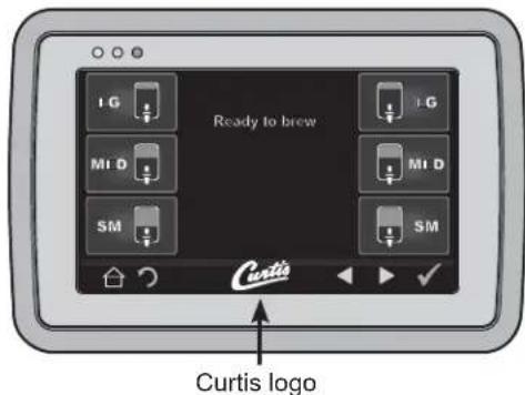

Diagnostics Screen
Button layout varies based model
Warning Messages - Allows Brewer to Continue Brewing
| MESSAGE DISPLAY WARNING DESCRIPTION CAUSE | ||
| Maintenance Required Maintenance Required | Brew count “Gallons Since Reset” exceeds programmed preventative maintenance period. | |
| Low Water Flow Warning | Low Water Flow | If the Inlet valve remains on longer than XX seconds (during the brew cycle only) and repeats TWICE during that brew cycle. It shall clear upon the next brew and if the same low flow exists again, it will re-appear. XX = Alpha 20 secs; Gem/TP Twin 40 secs; Gem/TP Single 30 secs. |
| Internal Error 2 | UPM-UCM have a mismatch in their settings. | UPM-UCM have a mismatch in their settings, firmware update needed. |
Error Messages - Brewer Will Stop Brewing
| MESSAGE DISPLAY ERROR DESCRIPTION CAUSE | ||
| Water Level Error Fill run error/Overflow | The water inlet valve has either been open for more than 10 minutes on the initial tank fill or has been open for 120 seconds on large brewers and 30 seconds on CGC, tea brewers in normal operation. | |
| Sensor Error Open Sensor | Break in the temperature thermistor circuit or short circuit. | |
| Over Temp. Error* Excess Temperature | The sensor is reading that temperature in the heating tank has risen above 210°F, or sensor has shorted to ground. | |
| Internal Error 1 UPM-UCM Communication | Break in the UPM-UCM communication circuit. | |
* This error is disabled on CGC and Seraphim models.
Wilbur Curtis Co., Inc. certifies that its products are free from defects in material and workmanship under normal use. The following limited warranties and conditions apply:
3 years, parts and labor, from original date of purchase on digital control boards
2 years, parts, from original date of purchase on all other electrical components, fittings and tubing
1 year, labor, from original date of purchase on all other electrical components, fittings and tubing
Additionally, Wilbur Curtis Co., Inc. warrants its grinding burrs for forty (40) months from the date of purchase or 40,000 pounds of coffee, whichever comes first. Stainless steel components are warranted for two (2) years from the date of purchase against leaking or pitting. Replacement parts are warranted for ninety (90) days from the date of purchase or for the remainder of the limited warranty period of the equipment in which the component is installed.
All in-warranty service calls must have prior authorization. For authorization, call the Technical Support Department at 800-995-0417.
Additional conditions may apply. Go to www.wilburcurtis.com to view the full product warranty information.
CONDITIONS & EXCEPTIONS
The warranty covers original equipment at time of purchase only. Wilbur Curtis Co., Inc., assumes no responsibility for substitute replacement parts installed on Curtis equipment that have not been purchased from Wilbur Curtis Co., Inc. Wilbur Curtis Co., Inc. will not accept any responsibility if the following conditions are not met. The warranty does not cover:
- Adjustments and cleaning: The resetting of safety thermostats and circuit breakers, programming and temperature adjustments are the responsibility of the equipment owner. The owner is responsible for proper cleaning and regular maintenance of this equipment.
- Replacement of items subject to normal use and wear: This shall include, but is not limited to, spray heads, faucets, light bulbs, shear disks, "O" rings, gaskets, silicone tubing, silicone elbows, canister assemblies, whipper chambers and plates, mixing bowls, agitation assemblies and whipper propellers.
The warranty is void under the following circumstances:
• Improper operation of equipment: The equipment must be used for its designed and intended purpose and function.
- Improper installation of equipment: This equipment must be installed by a professional technician and must comply with all local electrical, mechanical and plumbing codes.
• Improper voltage: Equipment must be installed at the voltage stated on the serial plate supplied with this equipment.
• Improper water supply: This includes, but is not limited to, excessive or low water pressure and inadequate or fluctuating water flow rate.
• Damaged in transit: Equipment damaged in transit is the responsibility of the freight company and a claim should be made with the carrier.
- Abuse or neglect (including failure to periodically clean or remove lime accumulations): The manufacturer is not responsible for variation in equipment operation due to excessive lime or local water conditions. The equipment must be maintained according to the manufacturer's recommendations.
Repairs and/or Replacements are subject to Curtis' decision that the workmanship or parts were faulty and the defects showed up under normal use. All labor shall be performed during regular working hours. Overtime charges are the responsibility of the owner. Charges incurred by delays, waiting time, or operating restrictions that hinder the service technician's ability to perform service is the responsibility of the owner of the equipment. This includes institutional and correctional facilities. Wilbur Curtis Co., Inc. will allow up to 100 miles, round trip, per in-warranty service call.
Return Merchandise Authorization (RMA): All claims under this warranty must be submitted to the Wilbur Curtis Technical Support Department prior to performing any repair work or return of this equipment to the factory. All returned equipment must be properly re-packaged in the original carton and received by Curtis within 45 days following the issuance of a RMA. No units will be accepted if they are damaged in transit due to improper packaging. NO UNITS OR PARTS WILL BE ACCEPTED WITHOUT A RETURN MERCHANDISE AUTHORIZATION (RMA). THE RMA NUMBER MUST BE MARKED ON THE CARTON OR SHIPPING LABEL. All warranty claims must be submitted within 60 days of service. Invoices will not be processed or accepted without a RMA number. Any defective parts must be returned in order for warranty invoices to be processed and approved. All in-warranty service calls must be performed by an authorized service agent. Call the Wilbur Curtis Technical Support Department to find an agent near you.
- G4 THERMOPRO® SERIES 1.5 GALLON COFFEE BREWING SYSTEM
- CONTENTS CL24
- CONTACT INFORMATION
- KEY FEATURES
- SPECIFICATIONS (SELECTED MODELS)
- SYMBOLS
- SANITATION REQUIREMENTS
- IMPORTANT SAFEGUARDS/CONVENTIONS
- WARNING
- CE REQUIREMENTS
- INSTALLATION INSTRUCTIONS
- INSTALLATION REQUIREMENTS
- INSTALLATION
- LEVELING
- CONNECT THE WATER SUPPLY
- CONNECT THE BREWER WIRING
- CONNECT THE BREWER WIRING (CONT.)
- POWER UP THE BREWER
- BREWING INSTRUCTIONS
- CLEANING THE BREWER - DAILY
- CLEANING THE BREWER - WEEKLY
- CLEANING THE 1.0 GALLON OR 1.5 GALLON THERMAL DISPENSERS (DAILY)
- CLEANING THE CONTAINER
- CLEANING THE FAUCET PARTS AND SITE GAUGE
- CLEANING INSTRUCTIONS CI5
- CLEANING THE FAUCET PARTS AND GAUGE GLASS (CONT.)
- CLEANING THE AIRPORT/POUR POT (DAILY)
- CLEANING AIRPOTS
- CLEANING POUR POTS
- TOUCHSCREEN CONTROL MODULE
- ENTERING PROGRAMMING MODE
- PROGRAMMING
- USB - EASY PROGRAMMING
- UPLOADING THE SOFTWARE TO THE FLASH DRIVE
- DOWNLOADING THE SOFTWARE TO THE BREWER FROM THE FLASH DRIVE
- USB FILE TRANSFER
- SUPPLIES AND ACCESSORIES - ALL MODELS
- TROUBLESHOOTING GUIDELINES
- VALVE TEST PROCEDURE
- WATER NOT HOT ENOUGH
- WATER HEATS MORE SLOWLY THAN USUAL
- DISPENSER OVERFLOWS DURING BREWING
- NO POWER - DISPLAY NOT LIT
- BREWER DOES NOT START WHEN BREW BUTTON IS PRESSED
- WATER TOO HOT (BOILING OR EXCESSIVE STEAMING)
- SENSOR ERROR MESSAGE
- WATER TANK OVERFILLS
- WATER TANK DOES NOT FILL
- COFFEE/TEA TOO STRONG
- DISPENSER NOT FILLED TO NORMAL LEVEL DURING BREWING
- DISPENSER OVERFLOWS ALL OF THE TIME
- NO WATER/TEA FLOWS FROM BREWER DURING BREWING
- LOW WATER FLOW WARNING
- WATER LEVEL ERROR MESSAGE
- INTERNAL ERROR 1" MESSAGE ON DISPLAY
- INTERNAL ERROR 2" MESSAGE ON DISPLAY
- WATER DOES NOT HEAT AT ALL
- OVER TEMP SENSOR ERROR MESSAGE
- OVERVIEW
- USING THE DIAGNOSTICS
- CONDITIONS & EXCEPTIONS
Brand : Wilbur Curtis
Model : G4 ThermoPro
Category : Coffee maker