
Mansfield L850B ST - Heating Regency - Free user manual and instructions
Find the device manual for free Mansfield L850B ST Regency in PDF.


| Product Type | See-Through Wood Fireplace (Inbuilt) |
| Brand | Regency |
| Model | Mansfield L850B ST |
| Overall Dimensions (Width x Depth x Height) | 1073 mm x 499 mm x 927 mm (without base frame; with optional base frame add 300 mm height) |
| Weight | Approx. 300 kg (unit only; base must support at least 332 kg) |
| Fuel Type | Natural hardwood only (seasoned air-dried, moisture <20%) |
| Maximum Heat Output (Hardwood) | 13 kW |
| Overall Efficiency (Hardwood) | 63% |
| Particulate Emission Factor | 1.3 g/kg |
| Flue System | Regency triple skin approved flue kit; minimum 4.6 m above floor protector; 50 mm clearance to combustibles |
| Minimum Enclosure Dimensions (Width x Depth x Height) | 1580 mm x 569 mm (finish dependent) x 2400 mm |
| Floor Protector Requirements | 9 mm thick non-combustible material, 1220 mm wide, 300 mm deep (recommended 900 mm in front) |
| Base Frame Height | Minimum 300 mm (non-combustible, hollow center for outside air) |
| Ventilation Grilles | Two grilles (one above, one below doors), minimum 8000 mm² open area each |
| Optional Fan Kit | Up to 2 fan kits, max 9 m duct run, 150 mm diameter flexible duct |
| Optional Outside Air Kit | Recommended for airtight homes; install before fireplace placement |
| Firebrick Material | Ceramic firebricks (sides, bottom) and baffle bricks (top) |
| Glass Type | Neoceram ceramic glass (replacement part #2510221) |
| Door Seal | 16 mm door rope seal (part #3720101A) |
| Controls | Single air slide control (primary and air wash); pull right to open, left to close |
| Warranty | 15 years on welded firebox steel (labor coverage varies); see manual for full details |
Frequently Asked Questions - Mansfield L850B ST Regency
User questions about Mansfield L850B ST Regency
0 question about this device. Answer the ones you know or ask your own.
Ask a new question about this device
Download the instructions for your Heating in PDF format for free! Find your manual Mansfield L850B ST - Regency and take your electronic device back in hand. On this page are published all the documents necessary for the use of your device. Mansfield L850B ST by Regency.
USER MANUAL Mansfield L850B ST Regency
Owners & Installation

REGENCY®
FIREPLACE PRODUCTS
SEE-THRU WOOD FIREPLACE
Model: MANSFIELD L850B ST
Manual

natural_image
Modern living room interior featuring a single fire extinguisher with visible flames, surrounded by wall-mounted wood and a large window (no text or symbols)PLEASE KEEP THESE INSTRUCTIONS FOR FUTURE REFERENCE
WARNING:
Improper installation, adjustment, alteration, service or maintenance can cause injury or property damage. Refer to this manual. For assistance or additional information consult an authorised installer, service agency or the distributor.
It is highly recommended for protection of infants and infirm to place a secure safety guard in front of this appliance when in operation.
Thank you for purchasing a REGENCY FIREPLACE PRODUCT
The pride of workmanship that goes into each of our products will give you years of trouble-free enjoyment. Should you have any questions about your product that are not covered in this manual, please contact the REGENCY DEALER in your area.
Keep those REGENCY FIRES burning.
SAFETY NOTE: If this wood fire is not properly installed, a house fire may result. For your safety, follow the installation instructions, contact local building, fire officials, or authority having jurisdiction about restrictions and installation inspection requirements in your area.
The authority having jurisdiction should be consulted before installation to determine the need to obtain a permit.
CAUTION: BURN UNTREATED WOOD ONLY. OTHER MATERIALS SUCH AS WOOD PRESERVATIVES, METAL FOILS, COAL, PLASTIC, GARBAGE, SULPHUR OR OIL WILL DAMAGE THE FIRE AND ATMOSPHERE.
"This wood heater is designed to burn natural wood only. Higher efficiencies and lower emissions generally result when burning air dried seasoned hardwoods, as compared to green or freshly cut hardwoods."
DO NOT BURN (WILL VOID WARRANTY):
- Treated wood
- Tea Tree
- Oil Based woods
- Coal
- Cardboard
- Solvents
- Colored Paper
- Household Waste

WARNING!

natural_image
Illustration of two hands reaching toward a red circular object with wavy lines, enclosed in a partial square frame (no text or symbols)HOT GLASS WILL CAUSE BURNS
DO NOT TOUCH GLASS UNTIL COOLED
ONLY CLEAN APPLIANCE WITH A DAMP CLOTH (NEVER WHEN UNIT IS HOT) DO NOT USE ANY ABRASIVE CLEANERS
table of contents
Copy of Data Badge 4
Unit Dimensions....5
Before Installing Your Fireplace....6
INSTALLATION ....7
Safety Guidelines and Warnings/Cautions......7
Unit Dimensions....8
Reduced Clearance Box Dimensions....8
Wood Fireplace Specifics and Minimum Clearances .....9
Flue Clearances to Combustibles ....10
Optional Base Frame 11
Flue Requirements ....12
Installation Instructions - Unit Preparation/Framing ...14
Installation Instructions -Unit Preparation/Framing and
Wall Finishing....17
Flue & Chimney Requirements....18
Optional Fan Kit Installation 20
Fan Duct Extension Kit....22
Wiring Diagram....22
Optional Outside Air Kit Installation 23
Firebrick Installation 24
MAINTENANCE 25
Appliance Maintenance....25
Creosote....25
Ash Removal....25
Glass Installation....25
Maintenance 25
Glass Maintenance 25
Door Latch Adjustment....25
OPERATING INSTRUCTIONS......26
Operating Instructions....26
Air Slide Control 26
Wood Storage 26
Lighting the Appliance & the First Few Fires ......27
Troubleshooting 28
PARTS LIST......29
WARRANTY....31
Installation of Appliance Checklist....31
Warranty 32
This is a copy of the data badge that accompanies each L850B ST Fireplace. We have included a copy of the contents here for your review.
NOTE: Regency units are constantly being improved. Check the data badge on the unit and if there is a difference, the data badge on the unit is the correct one.
COPY OF DATA BADGE
| MAKE: REGENCYTYPE: FIREPLACE INBUILT | |
| Model: MANSFIELD L850B ST | Serial Number 444 |
| TESTED BY: AUSTRALIA SOLID FUEL TEST REPORT NUMBER: ASFT16012-1 TESTING PTY LTD.3 GARDEN STREET, MORWELL VIC 3870WHEN TESTED IN ACCORDANCE WITH AS/NZS 4012:2014 & AS/NZS 4013:2014MAXIMUM AVERAGE HEAT OUTPUT BURNING HARDWOOD: 13 kWOVERALL AVERAGE EFFICIENCY BURNING HARDWOOD: 63%PARTICULATE EMISSION FACTOR: 1.3 g/kgCATALYTIC COMBUSTOR: NOMANUFACTURER/DISTRIBUTOR: FIREPLACE PRODUCTS AUSTRALIA PTY. LTD.99 COLEMANS ROAD, DANDENONG SOUTH VIC. 3175 | |
| Date of Manufacture:JAN FEB MAR APR MAY JUN JUL AUG SEP OCT NOV DEC 2021 2022 2023 2024 2025□ □ □ □ □ □ □ □ □ □ □ □ □ □ □ □ □ □ □ □ □ □ □ □ □ □ □ □ □ □ □ □ □ □ □ □ □ □ □ □ □ □ □ □ □ □ □ □ □ □ □ ▢ 919-639b | |
UNIT DIMENSIONS

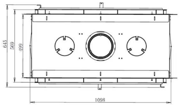

Note: All dimensions in millimetres.
installation
Regency Fireplaces are constructed with the highest quality materials and assembled under strict quality control procedures that ensure years of trouble free and reliable performance.
It is important that you read this manual thoroughly and fully understand the safe installation and operating procedures. The more you understand the way your Regency Fireplace operates, the more enjoyment you will experience from knowing that your unit is operating at peak performance.
BEFORE INSTALLING YOUR FIREPLACE
1) Please read this entire manual before you install and use your new wood fireplace. Failure to follow instructions may result in property damage, bodily injury or even death. Install and use only in accordance with manufacturer's installation and operating instructions.
2) Check your local building codes - Building Inspection Department. You may require a permit before installing your fireplace. Be aware that local codes and regulations may override some items in the manual.
3) Notify your home insurance company that you plan to install a wood heater.
4) THE FIREPLACE CAN GET VERY HOT. DO NOT INSTALL, PLACE OR POSITION TV'S, PAINTINGS, PICTURES, CANDLES, FURNITURE, DRAPES OR ANY OTHER COMBUSTIBLE ITEMS ON THE WALL OR NEAR THE FIREPLACE.
5) ENSURE THERE ARE NO EXHAUST FANS WITHIN THE VICINITY OF THE FIREPLACE AS THIS CAN CAUSE THE FIREPLACE TO EMIT FUMES BACK INTO THE ROOM.
6) ENSURE THERE IS ADEQUATE AIR SUPPLY WITHIN THE ROOM/AREA THE FIREPLACE IS BEING INSTALLED IN TO ENSURE PROPER OPERATION OF THE FIREPLACE. INSTALL OPTIONAL OUTSIDE AIR KIT IF IN DOUBT.
7) EVALUATE THE LOCATION OF YOUR FIREPLACE AND OPTIONAL COMPONENTS. IT IS VERY IMPORTANT TO DETERMINE HOW THE FIREPLACE IS GOING TO BE FINISHED. THE FEATURES YOU WOULD LIKE TO INCORPORATE SUCH AS FINISH TRIM, OUTSIDE AIR AND FAN KIT NEED TO BE EVALUATED BEFORE COMMENCING INSTALLATION.
8) DETERMINE WHAT THE THICKNESS OF YOUR DESIRED NON-COMBUSTIBLE FINISHING MATERIALS WILL BE INCLUDING THE NON-COMBUSTIBLE BOARD. THIS PREDETERMINED THICKNESS WILL DICTATE THE POSITION OF THE NAILING STRIPS, FRAMING AND OVERALL FINAL LOOK OF YOUR FIREPLACE.
9) Your fireplace is heavy and requires two or more people to move it safely. The fireplace can be badly damaged by mishandling and or injury can occur.
10) Do not connect the fireplace to a flue system servicing another appliance or an air distribution duct.
WARNING: CARELESS INSTALLATION IS THE MAJOR CAUSE OF SAFETY HAZARDS. CHECK ALL LOCAL BUILDING AND SAFETY CODES BEFORE INSTALLATION OF UNIT.
THE APPLIANCE, WHEN INSTALLED, MUST BE ELECTRICALLY GROUNDED IN ACCORDANCE WITH LOCAL CODES.
SAFETY GUIDELINES AND WARNINGS/CAUTIONS
1) Never use petrol, petrol type lantern fuels, kerosene, charcoal lighter fuel, or similar liquids to start or 'freshen up' a fire in your heater. Keep all such liquids well away from the heater while it is in use.
2) Keep the door closed during operation and maintain all seals in good condition.
3) Do not burn any quantities of paper, garbage, and never burn flammable fluids such as petrol, naptha or engine oil in your heater.
4) If you have smoke detectors, prevent smoke spillage as this may set off a false alarm.
5) Do not overfire heater. If the flue, flue baffle or the heater top begin to glow, you are overfiring. Stop adding fuel and close the air slide control and both doors. Overfiring can cause extensive damage to your heater including warpage and premature steel corrosion. Overfiring will void your warranty.
6) Do not permit creosote or soot build-up in the flue system. Check and clean flue at regular intervals. Failure to do so can result in a serious flue fire.
7) Your Regency heater can be very hot. You may be seriously burned if you touch the heater while it is operating, keep children, clothing and furniture away. Warn children of the burn hazard. For safety reasons a guard around the fire is recommended.
8) The heater consumes air while operating, provide adequate ventilation with an air duct or open a window while the heater is in use or use optional outside air kit.
9) Do not use grates or andirons or other methods for supporting fuel. Burn directly on the base or bricks where supplied.
10) Open the air slide control fully for 10 to 15 seconds prior to slowly opening the door when refuelling the fire.
11) Your wood fire should burn dry, hardwood, firewood only. The use of cut timber, plywood, "mill ends", etc. is not allowed as this fuel can easily overheat your wood fire. Evidence of excessive overheating will void your warranty. As well, a large portion of sawmill waste is chemically treated timber, which is illegal to burn in many areas. Salt drift wood and chemically treated fire logs also must not be burned in your wood fire.
WARNING
Ensure that curtains, blinds and drapes cannot extend to or anywhere near the fire as this could cause an extremely dangerous operating condition.
These must be secured by any means possible.
Examples not limited to :
If a window or door is opened, the wind/breeze could cause them to move.
Physical movement by an adolescent child.
WARNING: THE APPLIANCE AND FLUE-SYSTEM SHALL BE INSTALLED IN ACCORDANCE WITH AS/NZS 2918 AND THE APPROPRIATE REQUIREMENTS OF THE RELEVANT BUILDING CODE OR CODES. UNIT FLUEING REQUIRES A MINIMUM OF 50 MM CLEARANCE TO COMBUSTIBLES.
WARNING: APPLIANCES INSTALLED IN ACCORDANCE WITH THIS STANDARD SHALL COMPLY WITH THE REQUIREMENTS OF AS/NZS 4013 WHERE REQUIRED BY THE REGULATORY AUTHORITY. I.E. THE APPLIANCE SHALL BE IDENTIFIABLE BY A COMPLIANCE PLATE WITH THE MARKING 'TESTED TO AS/NZS 4013'.
ANY MODIFICATION OF THE APPLIANCE THAT HAS NOT BEEN APPROVED IN WRITING BY THE TESTING AUTHORITY IS CONSIDERED TO BE IN BREACH OF THE APPROVAL GRANTED FOR COMPLIANCE WITH AS/NZS 4013.
CAUTION: MIXING OF APPLIANCE OR FLUE-SYSTEM COMPONENTS FROM DIFFERENT SOURCES OR MODIFYING THE DIMENSIONAL SPECIFICATION OF COMPONENTS MAY RESULT IN HAZARDOUS CONDITIONS. WHERE SUCH ACTION IS CONSIDERED, THE MANUFACTURER SHOULD BE CONSULTED IN THE FIRST INSTANCE.
CAUTION: CRACKED AND BROKEN COMPONENTS, e.g. GLASS PANELS OR FIREBRICKS & BAFFLE BRICKS, ETC. MAY RENDER THE INSTALLATION UNSAFE.
WARNING: ANY MODIFICATION OF THE APPLIANCE THAT HAS NOT BEEN APPROVED IN WRITING BY THE TESTING AUTHORITY IS CONSIDERED AS BREACHING AS/NZS 4013.
WARNING: DO NOT USE FLAMMABLE LIQUIDS OR AEROSOLS TO START OR REKINDLE THE FIRE.
WARNING DO NOT USE FLAMMABLE LIQUIDS OR AEROSOLS IN THE VICINITY OF THIS APPLIANCE WHEN IT IS OPERATING.
WARNING: DO NOT STORE FUEL WITHIN HEATER INSTALLATION CLEARANCES.
WARNING: DO NOT USE AS AN OPEN FIRE OR OPERATE WITH THE DOOR OPEN.
WARNING: OPEN AIR SLIDE CONTROL BEFORE OPENING FIRE DOOR.
CAUTION: THIS APPLIANCE SHOULD BE MAINTAINED AND OPERATED AT ALL TIMES IN ACCORDANCE WITH THESE INSTRUCTIONS
CAUTION: THE USE OF SOME TYPES PRESERVATIVE-TREATED WOOD AS A FUEL CAN BE HAZARDOUS
CAUTION: THIS APPLIANCE SHOULD NOT BE OPERATED WITH CRACKED GLASS
installation
UNIT DIMENSIONS
Dimensions
The outside dimensions of the Mansfield L850B ST including the Reduced Clearance Box is as follows:
- Width = 1073 mm
- Depth = 499 mm
- Height = 927 mm
Height of optional Base Framing Kit = 300mm
Note: Base is non-combustible and needs assembly
Height of reduced clearance box off the ground should be a minimum of 300mm and supported by a non-combustible stand able to support 332kg.
Note: Depth is determined by the position of the nailing strips and thickness of non-combustible finished wall material.
Flue
The flue must be a Regency triple skin type with approved cowl and must extend a minimum of 4.6 metres above the top of the floor protector.
Optional Ducting
2 x Optional fan forced ducting kit are available, using 150 mm ducting to a max run of 9 metres to channel warm air to another location.
REDUCED CLEARANCE BOX DIMENSIONS


WOOD FIREPLACE SPECIFICS AND MINIMUM CLEARANCES
Framing and Finishing Guide
Finishing material must be flush with the outer edge of Clean Edge Finish – see page on Installation Instructions.
Finishing material must not protrude past the outer edge of Clean Edge Finish – see on Installation Instructions.
All walls of the enclosure must be a minimum of 9 mm non-combustible material compliant with AS1530-1 and AS1530-3.
Please note: when selecting non-combustible material, wall temperatures can exceed 250°C. Clean edge trim standoffs top and both sides are set at 22mm. Leave a minimum 10mm gap from bottom of clean edge trim to non combustible material to allow for expansion and contraction.
*Enclosure Depth = 569 mm – total thickness of finishing material on each side of the heater.
*Maximum finishing material thickness is 15 mm on the front & back face of the enclosure to ensure a minimum air gap of 20 mm between the face of the reduced clearance box and the back face of the finishing material on each side of the heater.
Enclosure depth is noted with nailing strips (top & sides) set for the correct total thickness of non-combustible finished wall material.
Ceiling inside of the cavity is to be 2.4 metres minimum.
Ceiling in the room is to be 2.4 metres minimum.
Ceiling can be of combustible materials.
Enclosure Width = 1580 mm minimum
Enclosure volume is critical and must not be reduced.
The enclosure must be fitted with an air ventilation grill centrally located below one of the door openings and centrally located above one of the door openings, as high as possible. Minimum 1080mm above top of fuel loading door. Both grills must be installed as per diagram below.
Floor Protector Requirements
Floor protector needs to be 9mm thick non-combustible material, 1220mm wide and 300mm deep extending out from door on both sides. We do recommend that your non-combustible floor protector extends 900mm in front of the unit. This allows the floor to be protected when the door is fully open in case of ember drop.
The appliance must be installed on a non-combustible stand 300mm above the floor protector.
Framing
When constructing the framework for the enclosure :
- All framing must be non-combustible material
- There must be a 25 mm clearance between any vertical or horizontal stud and the body of the reduced clearance box, to the sides and above the reduced clearance box.


NON COMBUSTIBLE FACING
MATERIAL & NON COMBUSTIBLE FRAME
MUST BE USED ON ENTIRE ENCLOSURE

FLUE CLEARANCE TO COMBUSTIBLES

- Ventilation grills = 2 grills, 1 below & 1 above fuel loading doors. Grills can be on the same or opposite sides of the enclosure. Require minimum 8000mm² of open area for each grill.
- Require unit to be raised minimum of 300mm from floor protector.
- Non-combustible board and steel framing is required for the entire enclosure however the ceiling may be of combustible material - see page 9 for minimum ceiling height.
- Clearances to combustibles for triple skin flue as it passes through ceiling, living spaces = 50mm.
- Non-combustible with walls of enclosure to be 9mm thick minimum.
OPTIONAL BASE FRAME


natural_image
Empty rectangular frame with dashed border and corner handles, no text or symbols present
CONSTRUCTING YOUR OWN BASE FRAME
WHEN BUILDING YOUR OWN BASE FRAME OR PEDESTAL BASE PLEASE ENSURE THE FOLLOWING CONDITIONS ARE MET:
- MINIMUM HEIGHT OF THE BASE FRAME IS 300MM FROM THE FLOOR PROTECTOR TO THE UNDERSIDE OF THE REDUCED CLEARANCE BOX. IF BASE FRAME DOES NOT SIT ON THE SAME LEVEL OF THE FLOOR PROTECTOR, THEN THE FRAME NEEDS TO BE MADE TALLER TO ENSURE THE 300MM CLEARANCE IS MET. (SEE PAGE 9).
- ENSURE THE CENTRE OF THE BASE IS HOLLOW TO ALLOW THE HOOK-UP OF THE OPTIONAL OUTSIDE AIR KIT.
- ENSURE THE BASE IS CONSTRUCTED OF NON-COMBUSTIBLE MATERIALS
- ENSURE THE BASE CAN WITHSTAND THE WEIGHT OF AT LEAST 332KG PLUS.
- ENSURE THE FLOOR BENEATH THE BASE CAN WITHSTAND AT LEAST 332KG PLUS.
- THE BASE CANNOT BE OF SOLID CONSTRUCTION. COOLING AIR MUST BE ALLOWED TO FLOW UNOBSTRUCTED ACROSS THE BOTTOM OF THE REDUCED CLEARANCE BOX.
FLUE REQUIREMENTS

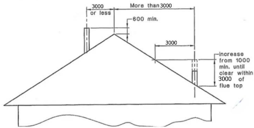
THE FLUE PIPE SHALL EXTEND NOT LESS THAN 4.6 M ABOVE THE TOP OF THE FLOOR PROTECTOR.
NOTE: INSTALLATION MUST BE CARRIED OUT BY A LICENSED INSTALLER IN ACCORDANCE WITH AS/NZS 2918:2018
FLUE REQUIREMENTS

Typical Example of a Sloped Ceiling Penetration
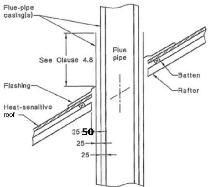
Example of Roof Penetration
installation
INSTALLATION INSTRUCTIONS UNIT PREPARATION/FRAMING
BEFORE INSTALLING ENSURE THE FOLLOWING:
READ THE ENTIRE MANUAL
EVALUATE THE LOCATION OF YOUR FIREPLACE AND LOCATION OF OPTIONAL COMPONENTS SUCH AS FAN, OUTSIDE AIR AND FINISH TRIMS.
DETERMINE THE THICKNESS OF YOUR DESIRED NON-COMBUSTIBLE FINISHING MATERIALS INCLUDING THE REQUIRED NON-COMBUSTIBLE BOARD. THIS PREDETERMINED THICKNESS WILL DICTATETHE ENCLOSURE DEPTH, POSITION OF THE NAILING STRIPS, FRAMING AND OVERALL FINAL LOOK OF YOUR FIREPLACE.
The unit comes standard with nailing strips and clean edge frame installed on both sides. The clean edge frame comes with 20 mm standoff brackets on the top edge plus left & right hand sides (not on bottom) to ensure clearance to finished wall material.
Clean edge frame: MAXIMUM THICKNESS OF FINISHING MATERIAL: 15MM
- Determine the location of the fireplace, flueing location and locations of the options such as the Fan Kit and outside air.
- Construct your base frame. Please see BASE FRAME instructions on page 11. The base frame is required TO RAISE THE UNIT in order to meet the 300mm clearance to the floor protector.

-
Install the floor protector (see page on Installation instructions).
-
Frame out side walls only of the fireplace enclosure. DO NOT FRAME FRONT OR BACK WALL. All framing for the walls of the enclosure need to be constructed using steel studs. Please refer to page on clearances for clearances and enclosure depth.
-
Install the base frame and secure to the floor / floor protector ensuring the frame is level.
-
Due to the large capacity of the firebox, most homes (especially 'air tight' 5 or 6 Energy Star Rates homes) will require an external air supply to ensure that the fire receives sufficient combustion air. If using optional outside air kit please refer to the outside air kit in this manual. The optional air kit adapter must be installed prior to the unit being positioned on to the base frame. Install flexible duct from air kit adapter to external air source.
-
Install the fireplace on the base frame. Secure fireplace to the base frame
INSTALLATION INSTRUCTIONS UNIT PREPARATION/FRAMING
- Frame out the front & back walls of the enclosure using steel studs - refer to pages of this manual for clearances. Leave a 5 mm gap from the side of the Reduced Clearance Bos to any horizontal or vertical steel stud to allow for expansion.
- You are now ready to install the flueing.
Please refer to Flue requirements in this manual then install your flue system.
- After the flue has been installed, complete the install of your optional kits such as fan/heat distribution kit(s) and/or outside air kit.
When cutting a rectangular opening in the finishing material to fit around the clean edge :
Width
The width of the opening must include the actual width of the clean edge finish (outside edge to outside edge) plus allow for the 20 mm stand-offs on the left & right sides
Height
The height of the opening must include the actual height of the clean edge finish (outside edge to outside edge) plus allow for the 20 mm stand-offs on the top edge plus a 5 mm air gap along the bottom edge
The actual position of the opening in the facing material will depend on site conditions, finished floor level, the height of the reduced clearance box off floor protector level, etc. We suggest, to avoid errors, that these measurements be taken when the heater is actually installed in its final location.
Framing Width = Fireplace Width (569mm) less 2 x Cladding Thickness

INSTALLATION INSTRUCTIONS UNIT PREPARATION/FRAMING
- Install the nailing strips. The unit comes with eight nailing strips. The top, left and right side are all the same and the bottom one is the smaller piece. Install the top and side nailing strips with the slotted side on the unit. The left and right nailing strips should NOT be touching the floor. Secure with the screws provided. Install the bottom small nailing strip and secure to the left and right vertical ones. DO NOT TIGHTEN SCREWS on the top, left and right nailing strips.

natural_image
Metal panel with circular features and a red arrow pointing to a small circular feature (no text or symbols visible)Nailing strip installed with slotted side on unit. The slot allows the movement of the nailing strip to be adjusted depending upon thickness of finish material.

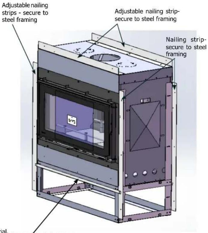
Bottom nailing strip-secure to left and right vertical nailing flanges
Note: Keep left and right nailing strips off the floor to allow for adjust ability
INSTALLATION INSTRUCTIONS UNIT PREPARATION / FRAMING & WALL FINISHING
IMPORTANT: DO NOT BEGIN FRAMING UNTIL THIS STEP HAS BEEN COMPLETED.
- Set the Adjustable Nailing Strips in position by using a piece of the non-combustible cladding and finishing material as a gauge.
- Hold the piece of cladding and finishing material flush with the front edge of the clean edge finish.
- Slide the Adjustable Nailing Strips so they are tight against the back of the non-combustible cladding material and tighten the screws to lock the angles in place.
- Repeat on the other side of the Mansfield fireplace.

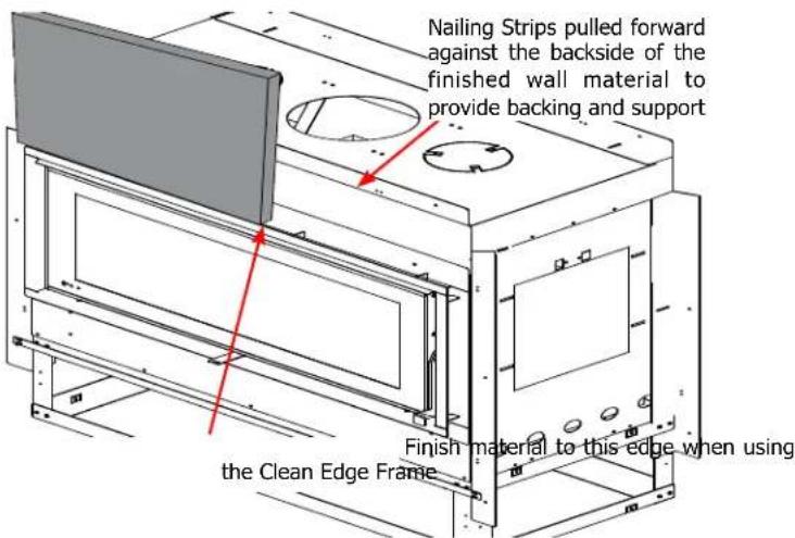
- Install the steel framing: Both walls require construction of non-combustible materials including the framing. Steel stud framing must be used. Install the left and right vertical steel frame and secure to the nailing strips. Position the steel frame behind the nailing strip. Install the top horizontal steel frame and secure to the top nailing strip.

- Finish constructing the remainder of the front wall using steel framing. Ensure the framing is level and plumb and there is enough framing to secure the required non-combustible finishing material.
- Install the non-combustible finishing material. Ensure there are no seams on the top and sides as these areas get extremely hot. Having no seams on the top and side will prevent cracking. Use only high heat non-combustible finishing material.
- ENSURE ALL ADHESIVES / GLUES ETC. ARE HIGH HEAT RESISTANT. ALLOW BONDING AGENTS TO CURE PROPERLY BEFORE FIRING UNIT.
FLUE AND CHIMNEY REQUIREMENTS
PLEASE READ AND REFER TO INSTALLATION INSTRUCTIONS UNIT PREPARATION ON PAGE 16
Top of Unit prior to installation of the flue.
NOTE: INSTALL REGENCY APPROVED FLUE KIT ONLY
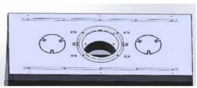
natural_image
Technical diagram of a mechanical component with three circular features and mounting brackets (no text or symbols)- Insert the 7" stainless steel starter piece. Note the crimped end is down (into unit).

natural_image
Top-down view of a ceiling-mounted cylindrical device with a circular opening, mounted on a white platform (no visible text or symbols)- Insert the 7" stainless steel active flue. Note: crimped end is down. Must connect active pipe using stainless steel rivets or self drilling screws. 2 for each join.

natural_image
Exterior view of a modern office building (no signage)- The first length of 9" / 11" galvanised flue is fitted with air cooling brackets.
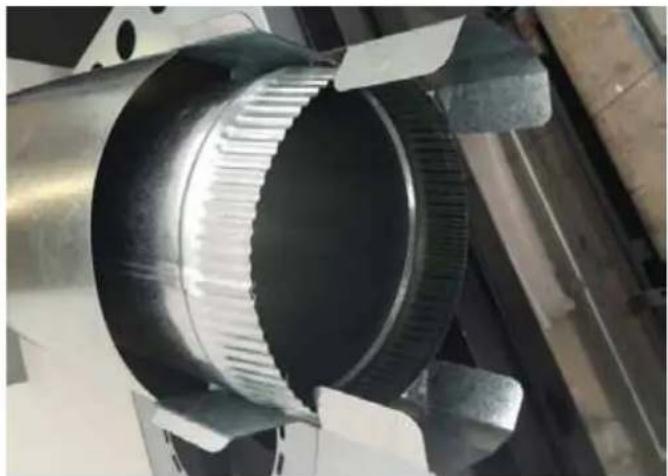
natural_image
Close-up of a metallic mechanical component with ribbed texture and metal brackets, no visible text or symbols- Insert the 9" & 11" galvanized flue skin fitted with aircooling bracket. Note: Crimped end of outer flue faces upwards.

natural_image
Close-up of a metallic cylindrical device with a reflective top, mounted on a workbench (no visible text or symbols)- Air cooled bracket and pipe fitted to unit

natural_image
Close-up of a metallic cylindrical component pressing into a circular opening, with no visible text or symbols.- The final length of 9" / 11" galvanized flue pipe has ventilation slots at the top where it meets the cowl - to allow heat to escape.
Note: Ventilation at top of outer flue where it meets cowl – must be vented to allow heat escape.
Note: 9" skin will be shorter than 11" at top – this is fine as allows 9" to vent into outer and cowl.
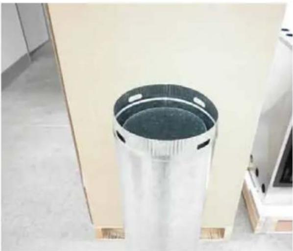
natural_image
Exterior view of a modern office building (no signage)At this stage of the installation the unit is installed with the flue system and any optional kits. The next step is to install and set the nailing strips in the correct position to accommodate the front wall framing and finishing.
OPTIONAL FAN KIT INSTALLATION
LISTINGS AND CODE APPROVALS
This Fan Kit has been approved for use with Mansfield L850B ST.
Check with your local building code agency before you begin your installation to ensure compliance with local codes, including the need for "permits" and follow-up inspections. If any problems are encountered regarding code approvals, or if you wish clarification on any of the instructions contained here, contact your local dealer.

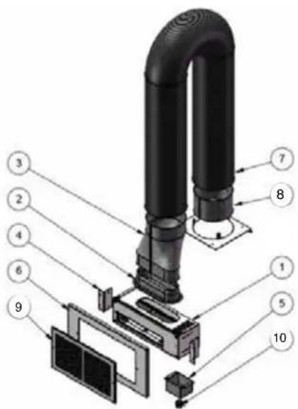
Diagram 1: Guide for possible air duct runs and locations. Keep duct length and number of bends to a minimum. Maximum duct length is 9.0m. The Fan Kit 946-591 does not contain any flexible duct. A separate Flex Kit is required 946-596. This Flex Kit contains one length of 4.5 metres of flex duct. If 9.0 metres of flex ducting is required you will need to purchase an additional Flex Kit.
| Item No. | Description No Description | |
| 1 240V | Fan Assembly | 7 Aluminum Flex 4.5m Long x 150 mm Round Diameter |
| 2 | Duct Flange-Fan End | |
| 3 | Adapter Round to Oval | 8 Duct Flange -Heater End |
| 4 Angle | Bracket 9 | Sidewall Grill |
| 5 | Junction Box | 10 Cable Clamp |
| 6 | Wall Adapter Plate |
GENERAL INFORMATION
The Fan Kit increases the effectiveness of your fireplace by dispersing warm air from the fireplace to remote locations in the same room or other rooms in your home.
Up to two kits may be installed on the fireplace.
Important Installation Notes
1) The appliance installation must conform with local codes and installation codes.
2) The appliance when installed, must be electrically grounded in accordance with local codes.
3) This kit is tested and safe when installed in accordance with this installation manual. Please read all instructions before starting installation and follow all instructions carefully during installation.
4) Installation of this kit must be performed by a qualified person.
5) The Fan Kit must be installed only as specified. Any modifications of the kit or components will void the warranty and may cause a fire hazard.
6) Plan the location of the fireplace and the warm air duct runs, see diagram 1 as a guide for possible duct runs and locations.
NOTE: Airflow through the duct system is affected by the duct length and number of bends. Keep the length and bends to a minimum to maximize performance.
MINIMUM FRAMING CLEARANCES
* Wall studs must be 407mm on centre for mounting fan housing.
* Fan Housing: Maintain a (6mm minimum) clearance from fan housing to combustible material.
* Wall Registers must be 102mm above floor and / or 102mm below ceiling.
1) Determine the location of the air register/fan housing assembly. Cut a 121mm x 406mm hole between framing members (wall studs or floor joists). Maintain a 6mm clearance from fan housing to combustible material. See Framing Clearances section.
Minimum Fan Duct Clearances
The fan ducting requires a minimum of 25 mm clearance to combustibles.

Minimum 102 mm from floor
NOTE: Installation of Fan Kit should be done prior to installation of the wall.
2) Mount and secure the fan housing assembly to framing. The mounting brackets are preset so that the front of the fan housing will protrude 12.7 mm out of the wall so that the front face will be flush with finished wall etc. See Diagram 2.
3) Install the flexible duct. Secure the duct to the duct collar on the unit and the fan housing with 3 screws per end.


Diagram 2: Side View - Secure fan housing to minimum 45mm framing.
Flexible Air Duct: Attach the 152.4 mm round air duct (supplied) to the fireplace collar and run the duct to the fan housing. Attach the round-to-oval adapter to the fan housing and the flex duct to the adapter.

4) Install the On/Off switch in a convenient location. This switch controls the fan operation.
NOTE: Variable speed or Rotary 3 speed switch (not supplied) can be fitted.
5) Wire up the fan, wall switch and power supply per local codes. See wiring diagram as reference.
*Electrician to supply wiring
6) Screw fan junction box to the fan housing.
7) Screw the Wall Adapter Plate and Grill to the Fan Housing. See Diagram 4.

8) Remove the knockout on the top of the unit.

natural_image
Close-up of a metallic mechanical component with a circular opening and an arrow pointing to a feature (no visible text or symbols)9) On the top of the unit, bend the 3 tabs so that they are pointed upwards. Insert the Duct collar. Secure the collar to the 3 tabs with screws.

10) The fan duct is now ready to be attached to the unit. Slide the ducting over the collar and secure with screws.

natural_image
Close-up of a metal coiled component being adjusted by a tool, no visible text or symbols11) Final step is to double check the fan ducting connections at both the unit and fan. Next ensure there is a minimum of 25mm clearance to combustibles, Strap and secure the fan duct. Double check the operation of the fan and all electrical work is completed.
FAN DUCT EXTENSION KIT
- Attach the connecting collar to the duct that came with the duct kit. Use the screws provided.

natural_image
Close-up of a hand operating a large metallic industrial hose with coiled tubing (no visible text or symbols)- Attach the 4.5m duct within this kit to the connecting collar on the opposite end with the screws provided. Extend the flex to the desired length.

natural_image
Close-up of a hand operating a metallic cylindrical tool with threaded end (no visible text or symbols)WIRING DIAGRAM

Alternate Switches: May use the following. Check with local authorities and electrician.
CLIPSAL 203 2E45 OUD - Dimmer
CLIPSAL 2031 VF3CSF - 3 Speed
Installation of wiring and switching must be carried out by a qualified electrician
Note: When using the supplied On / Off Switch or Dimmer (not supplied) remove the Red wire at the motor terminal or insulate the bare end of the Red wire (this connection is not used).
OPTIONAL OUTSIDE AIR KIT INSTALLATION
Due to the large capacity of the firebox, most homes (especially 'air tight' 5 or 6 Energy Star Rated homes) will require an external air supply to ensure that the fire receives enough combustion air. The Outside Air Kit cannot be fitted after the fireplace has been installed.
Provision will need to be made to extend the flex ducting for the Outside Air Kit to an external vent located through a wall, eaves or roof flume (not supplied).
When installing the outside air kit please ensure your pedestal base the unit sits on is hollow in the centre. The outside adapter attaches to the bottom of the unit. It is recommended not to down-size the outside air ducting.
- Evaluate your base frame. Ensure there is adequate space to allow the hook up of the adapter beneath the reduced clearance box.
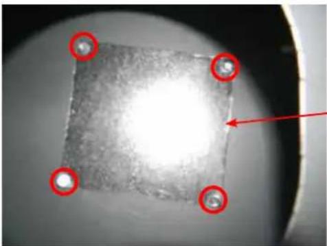
- Gently lay the unit on its back to access the bottom. Remove the cover plate located on the bottom of the reduced clearance box accessing the primary air control.
natural_image
Close-up of a square metallic object with red circular markers and a bright central spot, no visible text or symbols.Remove screws and Cover Plate
natural_image
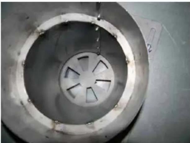
Close-up of a metallic circular component with a central radial feature and evenly spaced slots, no visible text or symbols.View with Cover Plate removed and unit adapter installed - primary air control now visible.
- Install the adapter ensuring it is centred on the primary air opening. Secure in place with the provided screws.
NOTE: The larger diameter end requires to be sitting below the unit. Small diameter end will insert into the bottom of the Reduced Clearance Box.

natural_image
Close-up of a black cylindrical mechanical part with a red arrow pointing to it, placed on a surface (no text or symbols visible)Large Diameter End to be Below Unit
- Stretch the 150 mm diameter flex duct out to the distance required. Attach the 150 mm diameter flex duct to the large diameter part that is protruding below the bottom of the unit. Use the screws provided.

natural_image
Close-up of a metal pipe wrapped in coiled black plastic, with tiled wall background (no visible text or symbols)- Cut a hole on your pre-determined outside wall to allow the fresh outside air hood to be installed. Install and secure the outside air hood. Seal around the flange to ensure tight seal against exterior of home. Join the 150 mm diameter flex duct from the unit adapter to the fresh air hood on the inside of the wall.

natural_image
Close-up of a hand using a power tool to cut a metallic cylindrical pipe (no visible text or symbols)installation
FIREBRICK INSTALLATION
Some firebricks are not in place at time of delivery to prevent damage.
Place 2 right and 2 left vertical bricks at sides of fireplace first.
Then place 2 bottom bricks in position.
3 x Baffle Bricks need to be placed in position at top of firebox.
Firebricks are included as an integral part of the unit and not only enhance operating performance hence compliance of the unit but also to extend the life of your firebox.
Bricks must be replaced if damaged in any way in order not to Void the Warranty

natural_image
3D rendering of a U-shaped mechanical component with two rectangular bases and a central slot (no text or symbols)APPLIANCE MAINTENANCE
CREOSOTE
When wood is burned slowly, it produces tar and other organic vapours, which when combined with moisture, form creosote. The creosote vapours condense in the relatively cool flue of a slow burning fire. As a result, creosote residue accumulates on the flue lining. When ignited, this creosote can result in an extremely hot fire.
WARNING: Things to remember in case of a flue fire:
-
Close both door & the air slide.
-
CALL THE FIRE BRIGADE.
Ways to Prevent and Keep Unit Free of Creosote
1) Burn heater with the air slide wide open for about 10-15 minutes every morning during burning season.
2) Burn heater with air slide control wide open for about 10 - 15 minutes every time you apply fresh wood. This allows the wood to achieve the charcoal stage faster and burns up any unburned gas vapours which might otherwise be deposited within the system.
3) Only burn seasoned hardwood! Avoid burning wet or green wood. Seasoned wood has been dried at least one year.
4) A small hot fire is preferable to a large smouldering one that can deposit creosote within the system.
5) The flue should be inspected at least once every two months during the heating season to determine if a creosote buildup has occurred.
6) Have flue system and unit cleaned by competent flue sweeps twice a year during the first year of use and at least once a year thereafter or when a significant layer of creosote has accumulated (3 mm) it should be removed to reduce the risk of a flue fire.
ASH REMOVAL
During constant use, ash should be removed every few days.
Safety Precautions
1) Do not allow ash to build up to the loading doors.
Only remove ash when the fire has died down.
Even then, expect to find a few hot embers.
2) The firebricks are brittle and can be damaged if logs that are too large or forced/thrown in.
3) Shovel out the ash into an appropriate container for removing ashes. The ash can still have hot embers so dispose of carefully. A large metal bucket designed for ash removal is recommended. It should come with a tight fitting lid and wire handle for carrying.
4) Leave about 25mm of ash in the firebox. It will make it easier to build and maintain a fire. The hot coals tend to nestle into the ash and glow, adding more heat to the fuel and reflecting the heat back into the fire.
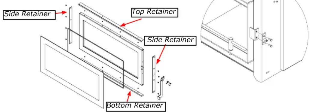
GLASS INSTALLATION
ALWAYS ENSURE APPROVED PERSONAL PROTECTIVE EQUIPMENT IS USED WHEN HANDLING DAMAGED GLASS
- Remove the door from the heater by lifting it up off hinge pins.
- Remove the top glass retainer.
- Loosen the bolts on the bottom retainer.
- Loosen screws on the left and right side retainers.
- Remove the glass carefully and keep it aside.
- Install a new glass seal onto the window frame.
- Install the new glass.
- Reverse steps 1-4 to reassemble the unit.
Replacement Glass Part Number: 2510221
MAINTENANCE
It is very important to carefully maintain your heater, including burning seasoned wood and maintaining a clean heater and flue system. Have the flue cleaned before the burning season and as necessary during the season, as creosote deposits may build up rapidly. Moving parts of your heater require no lubrication. The integrity of all heater parts including fire bricks, air tubes, door rope seals, and door glass seal is imperative for the correct operation and longevity of your Regency Wood heater. They should be inspected on a regular basis and replaced if they show any signs of undue wear or damage. Failure of any of these components can damage the heater and void warranty.
GLASS MAINTENANCE
Your Regency heater is supplied with Neoceram ceramic glass that will withstand the highest heat that your unit will produce. In the event that you break your glass by impact, purchase your replacement from an authorized Regency dealer only, and follow our step-by-step instructions for replacement.
Allow the heater to cool down before cleaning the glass, do not clean the glass when it is hot and do not use abrasive cleaners as both will damage the glass.
DOOR LATCH ADJUSTMENT
The door latch may require adjustment as the door rope seal material compresses over time.
Follow the steps below to allow the latch to be moved closer to the door frame, causing a tighter seal.
1) Loosen Door Latch securing bolts.
2) Move door latch back towards the firebox by a few millimetres to create a firmer door seal.
3) Retighten latch bolts.
operating instructions
OPERATING INSTRUCTIONS
With your unit now correctly installed and safety inspected by your local authority, you are now ready to start a fire. Before establishing your first fire, it is important that you fully understand the operation of your air slide control.
WARNING: ANY MODIFICATION OF THE APPLIANCE THAT HAS NOT BEEN APPROVED IN WRITING BY THE TESTING AUTHORITY IS CONSIDERED AS BREACHING AS/NZS 4013.
WARNING: DO NOT USE FLAMMABLE LIQUIDS OR AEROSOLS TO START OR REKINDLE THE FIRE.
WARNING: DO NOT USE FLAMMABLE LIQUIDS OR AEROSOLS IN THE VICINITY OF THIS APPLIANCE WHEN IT IS OPERATING.
WARNING: DO NOT STORE FUEL WITHIN HEATER INSTALLATION CLEARANCES. CAUTION: THIS APPLIANCE MUST BE MAINTAINED AND OPERATED AT ALL TIMES IN ACCORDANCE WITH THESE INSTRUCTIONS.
WARNING: OPEN AIR CONTROL (AND DAMPER WHEN FITTED) BEFORE OPENING FIRING DOOR.
CAUTION: THIS APPLIANCE SHOULD NOT BE OPERATED WITH A CRACKED GLASS.
CAUTION: THIS APPLIANCE SHOULD BE MAINTAINED AND OPERATED AT ALL TIMES IN ACCORDANCE WITH THESE INSTRUCTIONS.
CAUTION: THE USE OF SOME TYPES OF PRESERVATIVE-TREATED WOOD AS A FUEL CAN BE HAZARDOUS.
WARNING: OPEN THE AIR SLIDE BEFORE OPENING THE DOOR.
For safety reasons and in order to avoid over firing of your unit do not burn your fire with the door open or ajar.
AIR SLIDE CONTROL
Both the primary and air wash drafts are controlled by the air slide control located below the glass door. To increase your draft - pull right to open, and to decrease - push left. All units have a secondary draft system that continually allows combustion air to the induction ports at the top of the firebox.

natural_image
Technical line drawing of a right-open mechanical assembly with diagonal braces and a cylindrical component (no text or symbols)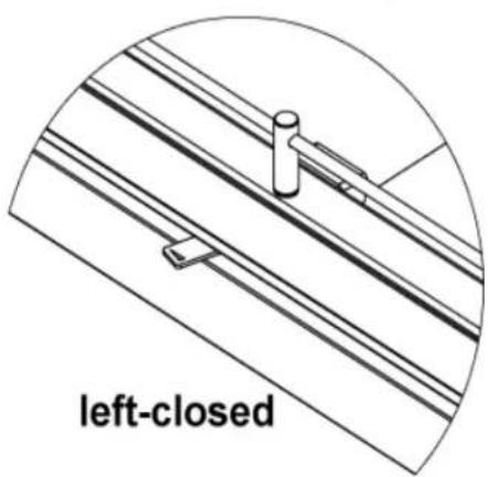
WARNING: To build a fire in ignorance or to disregard the information contained in this section can cause serious permanent damage to the unit and void your warranty!!
FUEL REQUIREMENTS
BURN ONLY HARDWOOD TIMBER THAT HAS BEEN SEASONED AND THE MOISTURE CONTENT OF THE LESS THAN 20%.
FRESHLY CUT WOOD REQUIRES AT LEAST 12-18 MONTHS TO BE READY FOR USE.
USING SEASONED TIMBER WITH PROPER MOISTURE CONTENT WILL ENSURE DRAFT, CLEAN GLASS, EFFICIENCY AND HEAT OUTPUTS.
CAUTION: BURN UNTREATED AIR DRIED SEASONED HARDWOODS ONLY. OTHER MATERIALS SUCH AS WOOD PRESERVATIVES, METAL FOILS, COAL, PLASTIC, GARBAGE, SULPHUR COAL, BRIQUETTES OR OIL WILL DAMAGE THE FIRE AND ATMOSPHERE AND VOID THE WARRANTY.
"This wood heater is designed to burn natural hardwood only. Higher efficiencies and lower emissions generally result when burning air dried seasoned hardwoods, as compared to green or freshly cut hardwoods."
DO NOT BURN
(WILL VOID WARRANTY)
- Treated wood
- Tea Tree
- Oil based woods
- Coal
- Cardboard
- Solvents
- Colored Paper
• Household Waste
SAVE THESE INSTRUCTIONS
WOOD STORAGE
Store wood under cover, such as in a shed, or covered with a tarp, plastic, tar paper, sheets of scrap plywood, etc., as uncovered wood can absorb water from rain or snow, delaying the seasoning process.
WARNING: Do not over-fire this unit and always open the door slowly when reloading
LIGHTING THE APPLIANCE AND THE FIRST FEW FIRES
operating instructions
When your installation is completed and inspected you are ready for your first fire.
1) Split wood into 3 stacks: Kindling, Start Up, (larger pieces than kindling) and firewood.
2) Open air slide control fully.
3) Open firebox door and build a small fire using paper and dry kindling on the firebrick base. Secure door on the firebox and wait a few minutes for a good updraft in the flue to establish the fire.
Add start up wood and spread across the unit. It is important to create airspaces within the pieces of start up wood for proper ignition and clean combustion. (Leaving the door slightly open will help your fire start more rapidly.
CAUTION: Never leave unit unattended if door is left open. This procedure is for fire start-up only, as unit may overheat if door is left open for too long.
4) With the air slide still in the fully open position add two or three seasoned logs to your fire. Form a trench in the ash bed to allow air to reach the rear of the firebox prior to closing the door.
5) After about 45 minutes, when your wood has begun to burn strongly, adjust your air slide control down to keep the fire at a moderate level.
WARNING: Never build a roaring fire in a cold heater. Always warm your heater up slowly!
6) Once a bed of coals has been established on the base of the firebox, you may adjust the air slide control to a lower setting to operate the unit at its most efficient mode.
7) During the first few fires, keep the combustion rate at a moderate level and avoid a large fire. Only after 5 or 6 such fires can you operate the heater at its maximum setting, and only after the metal has been warmed.
8) For the first few days, the heater will give off an odour from the paint. This is to be expected as the high temperature paint cures. Windows and/or doors should be left open to provide adequate ventilation while this temporary condition exists. Burning the heater at a very high temperature the first few times may damage the paint. Burn fires at a moderate level the first few days.
9) Do not place anything on the heater top during the curing process. This may result in damage to your paint finish.
10) During the first few days it may be more difficult to start the fire. As you dry out the firebrick and your masonry flue, the draft will increase.
(4.1) For those units installed at higher elevations or into sub-standard masonry fireplaces, drafting problems may occur. Consult an experienced dealer or mason on methods of increasing your draft.
12) Some cracking and popping noises may be experienced during the heating up process. These noises will be minimal when your unit reaches temperature.
13) Before opening your door to reload, open air slide fully for approximately 10 to 15 seconds until fire has been re-established. This will minimize any smoking. Open door slowly.
14) All fuel burning appliances consume oxygen during operation. It is important that you supply a source of fresh air to your unit while burning. A slightly opened window is sufficient for the purpose. If you also have an open fireplace in your home, a downdraft may be created by your Regency Heater causing a draft down your flue. If this occurs, slightly open a window near your unit.
CAUTION: If the body of your unit, flue baffle or any part of the flue starts to glow, you are over firing. Stop loading fuel immediately and close the draft control until the glow has completely subsided.
15) If you have been burning your heater on a low draft, use caution when opening the door. After opening the air slide, open the door a crack, and allow the fire to adjust before fully opening the door.
16) The controls of your unit or the air supply passages should not be altered to increase firing for any reason.
17) If you burn the unit too slowly or at too low a setting your unit will not be operating as efficiently as it can. An easy rule of thumb says that if your glass is clean, then your flue is clean and your exhaust is clean. Burn the heater hot enough to keep your glass clean and you won't need to clean your flue as often.
DO NOT OVERLOAD FIREPLACE OR COVER THE SECONDARY TUBES. ENSURE COALS / FUEL ARE BEHIND LOG RETAINER DO NOT OPEN DOOR WITH A ROARING FIRE OR WITH AIR CONTROL IN LOW POSITION. WHEN REFUELING ALWAYS ENSURE AIR CONTROL IS IN OPEN POSITION.
operating instructions TROUBLESHOOTING
| Symptom | Possible Cause | Solution |
| Fire will not start or starts slowly | The combustion air control is closed, or insufficient combustion air is reaching the fire. | Ensure that the air control is open and that the air inlet is free from debris. If necessary crack open the fireplace door until the fire is started. |
| Wet or insufficient kindling was used to try to start the fire | Use drier kindling and paper if necessary to start the fire. The initial burn helps to warm the flue and establish a proper draft. | |
| Trying to burn wet “fuel” wood will slow down the start | Use drier “fuel” wood for the fire, and allow more air space to start the fire. Wood should have a moisture content of 15-20% for best results. Use more kindling to dry the “fuel” wood. | |
| A negative air pressure in the home which can reverse or impede the natural flow of flue gasses. | Crack open a door or window, and turn off all exhaust devices. Typically increasing flue height will help to increase fireplace draw. | |
| A dirty or blocked flue or blocked air inlets can reverse or impede the natural flow of flue gasses. | Inspect the flue and fireplace for buildup or blockage and as necessary have the flue and fireplace cleaned. | |
| Dirty Glass | The air control may have been closed to soon, slowing down the burn of the fire, which will allow deposits to stick to the glass | Leave the air control open longer, at least 10-15 minutes every time you insert fresh wood, to ensure the fire has reached optimum temperature and properly established a draft. |
| Burning wet wood will slow the burn of the fire, produce more smoke, and allow unburned fuel to stick to the glass. | Use drier wood for the fire. Wood should have a moisture content of 15-20% for best results. | |
| A dirty flue, or an improperly sized or installed vent, will impede the flow of flue gasses slowing down the fire and allowing unburned fuel to stick to the glass. | Inspect the flue for buildup or blockage and to ensure that the proper size and configuration of venting was installed (refer to the Unit's manual) and as necessary have the flue cleaned, repaired, or replaced. | |
| An inadequate supply of combustion air will slow the burn and allow deposits to stick to the glass. | Ensure that air intakes are clean and clear of any debris. It may be necessary to install an outside air kit to provide adequate air supply. | |
| Worn seals will change the airflow of the fireplace and can allow deposits to stick to the glass. | Inspect and replace any worn seals to ensure proper airflow patterns within the unit. |
| Symptom | Possible Cause | Solution |
| Fire burning too fast | The door may have been left open, or the door latch may need adjustment. | Ensure that the door is properly closed and that when latched that the latch holds the door closed. If necessary adjust the latch (refer to the manual). |
| Worn seals will change the airflow of the fireplace and can increase the speed of the burn by bypassing the air control system. | Inspect and replace any worn seals to ensure proper airflow patterns within the unit. | |
| The air slide control may have been left open, allowing the fire to burn faster | Once the fireplace has reached optimum temperature, adjust the primary air control to maintain optimum burn. | |
| An overly tall flue may create an excessive draft, which will increase the speed of the burn. | Although heater pipe dampers are not recommended in today's EPA Certified units, it is possible to install a flue damper in the pipe at a height of 18" above the flue of the unit. This will restrict the flue gasses and help decrease the speed of the burn. | |
| CAUTIONIf the body of your unit starts to glow, you are overfiring the unit. STOP loading fuel immediately and close the air slide control & both doors until the glow has completely subsided. | ||
MAIN ASSEMBLY
| 1 251022 | Ceramic Glass (glass only) |
| 2 371020 | A Bottom Bricks (2pcs) |
| 3 371020 | B Side Bricks (2pcs) |
| 4 371020 | C Top Bricks (left top & right top) |
| 5 371020 | D Top Brick (middle top) |
| N/S 1560021 | Top, Left & Right Nailing Strips (6pcs) |
| N/S 1560022 | Bottom Nailing Strip (2pcs) |
| N/S 1638000 | Base Frame Kit* |
| N/S 1564007 | Deflector Hood |
| N/S 3720301 | P10 Glass Seal (2.3m) |
| N/S 1560110 | 50mm Finishing Trim with Box* |
| N/S = Not Shown * = optional accessory—not a spare part | |
| 1634200 30mm Finishing Trim with Box* | |
| 6 1639000 | Log Bar Support Assembly |
| 3720101A 16mm Door Rope Seal | |
| 7 1562100 | Door Frame Assembly (no glass) |
| 8 1562500 | Door Handle Assembly |
| 9 1566000 | Door Hinge |
| 10 1569000 | Adjustable Door Latch |
| 11 1563200 | Air Slide Assembly |
| N/S 1560019 | Door Opening Tool |
| 12 1633600 | Secondary Air Tube |
| 13 1562400 | Glass Retaining Set |
| 14 1634100 | Clean Edge Frame (with 20 mm standoffs) |

parts list
| # Part Description | |
| 1 910-169/P Replacement Fan Motor | |
| 2 946-001 Duct Flange | |
| 3 946-002 Round to Oval Adapter | |
| 4 946-007 Angle Bracket | |
| 5 946-004 Junction Box | |
| 6 946-005-AWT Wall Adapter Plate White | |
| 7 948-357 Adapter Round | |
| 8 946-093F Duct Mounting Plate | |
| 9 946-000 Duct Flange Collar | |
| 10 946-006 Side Grill White | |
| 11 904-687 Connector Clamp | |

INSTALLATION OF APPLIANCE CHECKLIST
For future reference and to assist in any warranty claim please complete the following information.
In the unlikely event of a problem, contact your installer or dealer for assistance:
APPLIANCE WAS PURCHASED FROM
Name: ____
Address:
Telephone Number: ____
MODEL DETAILS
Date Installed: ____
Model Description: ____
Serial Number:
INSTALLED BY
Company Name: ____
License Number: ____
Plumber Name: ____
Address:
Telephone Number:
COMMISSIONING CHECKS (TO BE COMPLETED AND SIGNED)
Is flue system set up in accordance with AS2918
YES NO
Smoke and Spillage test completed
YES NO
Use of appliance and operation of controls explained
YES NO
Clearance to combustible materials checked
YES NO
Installers Signature: ____
Print Name: ____
Date:
Limited Warranty
FPI Fireplace Products International Ltd. ("the manufacturer") through its wholly owned subsidiary, Fireplace Products Australia Pty Ltd (for Australia and New Zealand customers) and sold under the Regency® brand of fireplace products (collectively referred to herein as "FPI"), extends this Limited Warranty to the original purchaser of this appliance provided the product remains in the original place of installation. The items covered by this limited warranty and the period of such coverage is set forth in the table below.
Some conditions apply (see below).
The policy is not transferable, amendable or negotiable under any circumstances.
| Wood Products | Component Coverage | Labor Coverage | |||
| Components Covered | 15 years | 2 years | 1 year | Warranty | (Years) |
| Welded Firebox Steel | √ | 5 | |||
| All Stainless Steel Components, Smoke Deflectors, Heat Shields etc. | √ | 1 | |||
| Air Tubes | √ | 1 | |||
| Airmate | √ | 1 | |||
| Door handle and latch assembly, all hardware | √ | 1 | |||
| Glass Thermal Breakage Only | √ | 1 | |||
| Steel Faceplates, Accessory Housings | √ | 1 | |||
| All Plating | √ | 1 | |||
| Ash Drawer, Heatshields, Pedestal | √ | 1 | |||
| All Baffles-Steel, Ceramic, Vermiculite | √ | 1 | |||
| All castings, firebox, surrounds, doors, panels etc. | √ | 1 | |||
| All Electrical, Fans, wiring, switches etc. | √(Fan only) | √ | 1 | ||
| Glass - Crazing | √ | 1 | |||
| Catalyst Assembly (see below for specific details) | 6 Years Prorated | 3 | |||
| Flue components | √ | 1 | |||
| Firebricks | Nil | Nil | |||
After the original warranty coverage for any of the parts above have expired, any repair and/or replacement parts purchased by the consumer from FPI or through an accredited distributor or dealer will carry a ninety (90) day warranty (valid only with an original copy of the tax invoice). No labor coverage is included with any repair and/or replacement part.
Replacement parts are limited to one per warranty term. Airtube and baffle replacements are limited to one replacement per term.
Catalyst Assembly
IMPORTANT WARRANTY INFORMATION FOR UNITS WITH A CATALYTIC CONVERTER
FPI will replace, at no charge to the consumer, 'one' catalytic converter that ceases to function within three (3) years from the date of purchase by the original consumer, provided that the following conditions are met:
(1) The catalytic converter must not have been mechanically abused
(2) Only recommended fuels have been used in the appliance
If after three (3) years the catalytic converter fails to function, a prorated warranty will provide for replacement at the following fee schedule to be paid by the consumer*:
Year 4....\$90*
Year 5......\$100*
Year 6......\$110*
* Prices subject to change without notice. Conditions (1) and (2) above also apply for prorated warranty periods.
AFTER YEAR SIX (6), THE CONSUMER MUST PURCHASE ANY CATALYTIC CONVERTERS THAT NEED REPLACEMENT AT THE CURRENT RETAIL PRICE, AND WILL BE RESPONSIBLE FOR ANY LABOUR COSTS TO REMOVE AND/OR SERVICE. LABOR WILL ONLY BE COVERED ON THE CATALYTIC CONVERTER FOR THE FIRST THREE (3) YEARS.
Conditions:
Warranty protects against defect in manufacture or FPI factory assembled components only, unless herein specified otherwise. This warranty will only apply to those products which are acquired at the time of this warranty being effective. FPI will not be liable for any damage or loss that falls outside the scope of the warranty.
Any part(s) found to be defective during the warranty period as outlined above will be repaired or replaced at FPI's option through an accredited distributor, dealer or pre-approved and assigned agent provided that the defective part is returned to the distributor, dealer or agent for inspection if requested by FPI. Alternatively, FPI may at its own discretion fully discharge all of its obligations under the warranty by refunding the verified purchase price of the product to the original purchaser. The purchase price must be confirmed by an original copy of the tax invoice.
The authorised selling dealer, or an alternative authorised FPI dealer if pre-approved by FPI, is responsible for all in-field diagnosis and service work related to all warranty claims. This warranty does not cover dealer travel costs for diagnostic or service work. Dealers may charge homeowner for travel and additional time. Check with your selling dealer in advance for any costs to you when arranging a warranty call. FPI is not responsible for results or costs of workmanship of unauthorised FPI dealers or agents in the negligence of their service work. Additional service fees may apply if you are seeking warranty service from a dealer other than the dealer from whom you originally purchased the product.
At all times FPI reserves the right to inspect reported complaints on location in the field claimed to be defective and determine whether the warranty will apply prior to processing or authorising of any claim. Failure to allow this upon request will void the warranty.
All warranty claims must be submitted by the dealer servicing the claim, including an original copy of the tax invoice (proof of purchase by you). All claims must be complete and provide full details as requested by FPI to receive consideration for evaluation, including proof of maintenance records. Incomplete claims may be rejected. FPI has absolute discretion to assess and determine any warranty claim and may accept or reject a claim as it considers appropriate. Any part or parts of the unit found to be defective will be repaired or replaced at FPI's option, through an accredited distributor or service agent provided that the defective part be returned to the distributor or agent, Transportation Prepaid, if requested. It is the general practice of FPI to charge for larger, higher priced replacement parts and issue credit once the replaced component has been returned to FPI and evaluated for manufacturer defect.
If a consumer has a unit installed outside an accredited distributor, dealer or pre-approved service agent's service area, or the closest approved service agent is situated more than thirty (30) kilometres from the installation, FPI is not obliged to arrange warranty repairs or shipping/transportation costs. In these cases, the consumer must arrange warranty service with its selling dealer, and shipping, travel and/or additional labor charges will apply.
Unit must be installed according to all manufacturers' instructions as per the manual.
All Local and National required codes must be met.
The installer is responsible to ensure the unit is operating as designed at the time of installation.
The original purchaser is responsible for annual maintenance of the unit, as outlined in the owner's manual. As outlined below, the warranty may be voided due to problems caused by lack of maintenance. Annual maintenance records should be retained.
Exclusions:
This Limited Warranty does not extend to paint, rust or corrosion of any kind due to a lack of maintenance or improper venting, combustion air provision, corrosive chemicals (i.e. chlorine, salt, air, etc.), firebrick (rear, sides or bottom), door or glass gasket, or any other additional factory fitted gasket.
Malfunction, damage or performance based issues as a result of environmental conditions, location, chemical damages, downdrafts, installation error, installation by an unqualified installer, incorrect chimney components (including but not limited to cap size or type), operator error, abuse, misuse, use of improper fuels (such as unseasoned timber, mill-ends, construction timber or debris, off-cuts, treated or painted timber, tea tree, metal or foil, plastics, garbage, solvents, cardboard, coal or coal products, oil based products, waxed cartons, compressed pre-manufactured logs), accidents, lack of regular maintenance and upkeep, acts of God, weather related problems from hurricanes, tornadoes, earthquakes, floods, lightning strikes/bolts or acts of terrorism or war, which result in malfunction of the appliance are not covered under the terms of this Limited Warranty.
FPI has no obligation to enhance or modify any unit once manufactured (i.e. as products evolve, field modifications or upgrades will not be performed on existing appliances).
Any unit showing signs of neglect or misuse will not be covered under the terms of this warranty policy and may void this warranty. This includes units with rusted or corroded fireboxes which have not been reported as rusted or corroded within three (3) months of installation/purchase. Any alteration to the unit which causes sooting or carboning that results in damage to the exterior fascia or over firing that can cause component or firebox/heat exchanger failure will not be covered by this warranty.
Units which show evidence of being operated while damaged, or with problems known to the purchaser and causing further damages will void this warranty.
Units where the serial no. has been altered, deleted, removed or made illegible will void this warranty.
Minor movement, expansion and contraction of the steel is normal and is not covered under the terms of this warranty.
Freight damages for products or parts are not covered under the terms of the warranty.
Porcelain/Enamel: Absolute perfection is neither guaranteed nor commercially possible. Any chips must be reported and inspected by the authorised selling dealer within three (3) days of installation. Any damage of this type not reported after this time period will be subject to rejection and any related warranty will not apply.
Special Finishes: Expect some changes in color as the product "ages" with constant heating and cooling. The manufacturer warranty does not cover tarnishing, changing colors and/or marks (i.e. finger prints, etc.) after the purchase of the product. Damage from the use of abrasive cleaners is not covered by warranty.
Products made or provided by other manufacturers and used in conjunction with the FPI appliance without prior authorisation from FPI may void this warranty.
INCORRECT INSTALLATION IS NOT COVERED BY WARRANTY. A SERVICE OR CALLOUT FEE WILL BE CHARGED IN THESE CIRCUMSTANCES.
Limitations of Liability:
1. Exclusion of implied terms
The customer may have the benefit of consumer guarantees under the Australian Consumer Law. To the maximum extent permitted by law, all terms, conditions or warranties that would be implied into this Warranty or in connection with the supply of any goods or services by the supplier under law or statute or custom or international conventions are excluded.
2. Limitation of liability
(a) To the maximum extent permitted by law and subject to clauses 1 and 3, the supplier's total liability arising out of or in connection with its performance or its obligations pursuant to this Warranty, or arising out of or in connection with the supply of specific goods or services (including pursuant to or for breach of this Warranty, under statute, in equity or for tort, including negligent acts or omissions) is limited as follows: (i) the supplier shall have no liability to the customer for any Consequential Loss; (ii) without limiting the effect of clause 2(a)(i), the supplier's total aggregate liability for Loss, however arising, shall not exceed the GST exclusive aggregate price paid by the customer to the supplier for the specific goods or services that gave rise to the Loss in question.
(b) The limitations and exclusions in this sub-clause do not apply to the extent that any Loss is directly attributable to: (i) the personal injury or death caused by the supplier's default, breach of this Warranty or negligence; or (ii) fraud by the supplier.
(c) Each party must take reasonable steps to mitigate any Loss it suffers or incurs.
3. Limitation of liability under Australian Consumer Law Guarantees
(a) To the extent that goods supplied by the supplier are not goods of a kind ordinarily acquired for personal, domestic or household use and the customer is deemed to be a consumer for the purposes of section 64A of the Australian Consumer Law, the customer agrees that the supplier's liability for a failure to comply with a consumer guarantee that the customer may have a benefit under the Australian Consumer Law (other than a guarantee under sections 51 (title), 52 (undisturbed possession) and 53 (undisclosed securities)), is limited to, at the option of the supplier, one or more of the following: (i) replacement of the goods or the supply of equivalent goods; (ii) the repair of the goods; (iii) the payment of the cost of replacing the goods or of acquiring equivalent goods; or (iv) equivalent goods; or (v) the payment of the cost of having the goods repaired.
(b) To the extent that services supplied by the supplier are services other than services of a kind ordinarily acquired for personal, domestic or household use or consumption, the supplier's liability for failure to comply with a consumer guarantee that the customer may have the benefit of is limited to, at the option of the supplier: (i) the supply of the services again; or (ii) the payment of the cost of having the services supplied again.
4. Subject to Change
This Limited Warranty is given at the time of sale and purchase of the relevant fireplace product. The terms of this Limited Warranty may be amended from time to time by FPI in accordance with changes to business practices, consumer laws or other legal requirements. The rights and protections granted under the Limited Warranty are those in force in relation to a fireplace product at the time and in the place of sale of that product, and only those terms will be applicable in respect of that product.
5. Severability
Any term of this Limited Warranty that is invalid or unenforceable in any jurisdiction is to be read down for the purposes of that jurisdiction, if possible, so as to be valid and enforceable, and is otherwise capable of being severed to the extent of the invalidity or unenforceability, without affecting the remaining provisions of this Limited Warranty or affecting the validity or enforceability of that provision in any other jurisdiction.
6. Definitions
For purposes of clauses 1, 2 and 3:
(a) Consequential Loss means loss of expected savings, loss of use, loss of opportunity, loss of profit, loss of revenue, increased financing costs, loss arising from delay, or any consequential, special or indirect loss or damage, whether or not the possibility or potential extent of the loss or damage was known or foreseeable, and whether arising from a claim under indemnity, contract, tort (including negligence), statute or otherwise.
(b) Loss means any expense, cost or damage of any kind and includes Consequential Loss and a fine or penalty imposed by a statutory or other authority.
How to Obtain Warranty Service:
Customers should contact the authorised selling dealer to obtain warranty service. In the event the authorised selling dealer is unable to provide warranty service, please contact FPI by mail at the address listed below. Please include your name, address, purchase date, selling dealer, serial #, type of unit, a brief description of the problem, email and telephone contact information, and a copy of your original tax invoice. A representative will contact you to make arrangements for an inspection and/or warranty service. (See below for Western Australia and/or New Zealand)
Please note Fireplace Products Australia Pty Ltd does not provide installation services.
Fireplace Products Australia Pty Ltd
99 Colemans Road
Dandenong South, VIC
Australia, 3175
Phone: +61 3 9799 7277
Fax: +61 3 9799 7822
To obtain warranty service in Western Australia and/or New Zealand, please contact one of our authorised distributors in those areas:
Western Australia:
New Zealand:
Air Group Australia
131 Bannister Rd
Canning Vale WA
Australia, 6155
Phone: (08) 9350 2200
Fax: (08) 9353 4225
Aber Holdings Ltd
PO Box 10095
Te Rapa, Hamilton
New Zealand, 3241
Freephone: 0800 161 161
Product Registration and Customer Support:
Thank you for choosing a Regency Fireplace. Regency strives to be a world leader in the design, manufacture, and marketing of hearth products. To provide the best support for your product, we request that you complete a product registration form at http://www.regency-fire.com.au/Customer-Care/Warranty-Registration.aspx within ninety (90) days of purchase.
Product Registration and Customer Support:
Thank you for choosing a Regency Fireplace. Regency strives to be a world leader in the design, manufacture, and marketing of hearth products. To provide the best support for your product, we request that you complete a product registration form found on our Web Site under Customer Care within ninety (90) days of purchase.
For purchases made in CANADA or the UNITED STATES:
http://www.regency-fire.com/Customer-Care/Warranty-Registration.aspx
For purchases made in AUSTRALIA:
http://www.regency-fire.com.au/Customer-Care/Warranty-Registration.aspx
You may also complete the warranty registration form below to register your Regency Fireplace Product and mail and/or fax it back to us, and we will register the warranty for you. It is important you provide us with all the information below in order for us to serve you better.
Warranty Registration Form (or Register online immediately at the above Web Site):
| Warranty Details | |
| Serial Number (required): | |
| Purchase Date (required) (mm/dd/yyyy): | |
| Product Details | |
| Product Model (required): | |
| Dealer Details | |
| Dealer Name (required): | |
| Dealer Address: | |
| Dealer Phone #: | |
| Installer: | |
| Date Installed (mm/dd/yyyy): | |
| Your Contact Details (required) | |
| Name: | |
| Address: | |
| Phone: | |
| Email: | |
For purchases made in CANADA:
For purchases made in the UNITED STATES:
For purchases made in AUSTRALIA:
FPI Fireplace Products
International Ltd.
6988 Venture St.
Delta, British Columbia
Canada, V4G 1H4
Fireplace Products US, Inc.
PO Box 2189 PMB 125
Blaine, WA
United States, 98231
Fireplace Products Australia Pty Ltd
99 Colemans Road
Dandenong South, Vic. 3175
Australia
Phone: 604-946-5155
Fax: 1-866-393-2806
Phone: 604-946-5155
Fax: 1-866-393-2806
Phone: +61 3 9799 7277
Fax: +61 3 9799 7822
warranty
Installer: Please complete the following information
Dealer Name & Address: ____
Installer:
Phone #: ____
Date Installed: ____
Serial #: ____
- Owners & Installation
- REGENCY®
- FIREPLACE PRODUCTS
- SEE-THRU WOOD FIREPLACE
- Manual
- PLEASE KEEP THESE INSTRUCTIONS FOR FUTURE REFERENCE
- WARNING:
- Thank you for purchasing a REGENCY FIREPLACE PRODUCT
- DO NOT BURN (WILL VOID WARRANTY):
- WARNING!
- table of contents
- INSTALLATION ....7
- MAINTENANCE 25
- OPERATING INSTRUCTIONS......26
- PARTS LIST......29
- WARRANTY....31
- COPY OF DATA BADGE
- UNIT DIMENSIONS
- installation
- BEFORE INSTALLING YOUR FIREPLACE
- SAFETY GUIDELINES AND WARNINGS/CAUTIONS
- WARNING
- Dimensions
- Flue
- Optional Ducting
- WOOD FIREPLACE SPECIFICS AND MINIMUM CLEARANCES
- Framing and Finishing Guide
- Floor Protector Requirements
- Framing
- FLUE CLEARANCE TO COMBUSTIBLES
- OPTIONAL BASE FRAME
- CONSTRUCTING YOUR OWN BASE FRAME
- WHEN BUILDING YOUR OWN BASE FRAME OR PEDESTAL BASE PLEASE ENSURE THE FOLLOWING CONDITIONS ARE MET:
- FLUE REQUIREMENTS
- INSTALLATION INSTRUCTIONS UNIT PREPARATION/FRAMING
- When cutting a rectangular opening in the finishing material to fit around the clean edge :
- Width
- Height
- INSTALLATION INSTRUCTIONS UNIT PREPARATION / FRAMING & WALL FINISHING
- IMPORTANT: DO NOT BEGIN FRAMING UNTIL THIS STEP HAS BEEN COMPLETED.
- FLUE AND CHIMNEY REQUIREMENTS
- PLEASE READ AND REFER TO INSTALLATION INSTRUCTIONS UNIT PREPARATION ON PAGE 16
- OPTIONAL FAN KIT INSTALLATION
- LISTINGS AND CODE APPROVALS
- GENERAL INFORMATION
- Important Installation Notes
- MINIMUM FRAMING CLEARANCES
- Minimum Fan Duct Clearances
- FAN DUCT EXTENSION KIT
- WIRING DIAGRAM
- OPTIONAL OUTSIDE AIR KIT INSTALLATION
- FIREBRICK INSTALLATION
- APPLIANCE MAINTENANCE
- CREOSOTE
- WARNING: Things to remember in case of a flue fire:
- Ways to Prevent and Keep Unit Free of Creosote
- ASH REMOVAL
- Safety Precautions
- GLASS INSTALLATION
- ALWAYS ENSURE APPROVED PERSONAL PROTECTIVE EQUIPMENT IS USED WHEN HANDLING DAMAGED GLASS
- MAINTENANCE
- GLASS MAINTENANCE
- DOOR LATCH ADJUSTMENT
- operating instructions
- AIR SLIDE CONTROL
- FUEL REQUIREMENTS
- (WILL VOID WARRANTY)
- SAVE THESE INSTRUCTIONS
- WOOD STORAGE
- LIGHTING THE APPLIANCE AND THE FIRST FEW FIRES
- CAUTION: If the body of your unit, flue baffle or any part of the flue starts to glow, you are over firing. Stop loading fuel immediately and close the draft control until the glow has completely subsided.
- DO NOT OVERLOAD FIREPLACE OR COVER THE SECONDARY TUBES. ENSURE COALS / FUEL ARE BEHIND LOG RETAINER DO NOT OPEN DOOR WITH A ROARING FIRE OR WITH AIR CONTROL IN LOW POSITION. WHEN REFUELING ALWAYS ENSURE AIR CONTROL IS IN OPEN POSITION.
- operating instructions TROUBLESHOOTING
- INSTALLATION OF APPLIANCE CHECKLIST
- APPLIANCE WAS PURCHASED FROM
- MODEL DETAILS
- INSTALLED BY
- COMMISSIONING CHECKS (TO BE COMPLETED AND SIGNED)
- Limited Warranty
- Catalyst Assembly
- Conditions:
- Exclusions:
- Limitations of Liability:
- Exclusion of implied terms
- Limitation of liability
- Limitation of liability under Australian Consumer Law Guarantees
- Subject to Change
- Severability
- Definitions
- How to Obtain Warranty Service:
- Fireplace Products Australia Pty Ltd
- Air Group Australia
- Aber Holdings Ltd
- Product Registration and Customer Support:
- warranty
Brand : Regency
Model : Mansfield L850B ST
Category : Heating