N227P - Freezer Delfield - Free user manual and instructions
Find the device manual for free N227P Delfield in PDF.

| Product Type | Freezer |
| Brand | Delfield |
| Model | N227P |
| Width | 27 inches |
| Depth | 30 inches |
| Height | 74 inches |
| Weight | 250 lbs |
| Electrical Supply | 115V, 60Hz, 1 Phase |
| Amperage | 5.5 Amps |
| Plug Type | NEMA 5-15P |
| Temperature Range | -10°F to 0°F (-23°C to -18°C) |
| Capacity | 20 cubic feet |
| Number of Shelves | 4 adjustable wire shelves |
| Door Type | Solid door with lock |
| Refrigerant | R404A |
| Defrost Type | Automatic electric defrost |
| Interior Material | Stainless steel |
| Exterior Material | Stainless steel front, Galvanized sides |
| Insulation Type | High-density polyurethane foam |
| Castors | 4 adjustable castors with brakes |
| Warranty | 3 years parts and labor |
Frequently Asked Questions - N227P Delfield
User questions about N227P Delfield
0 question about this device. Answer the ones you know or ask your own.
Ask a new question about this device
Download the instructions for your Freezer in PDF format for free! Find your manual N227P - Delfield and take your electronic device back in hand. On this page are published all the documents necessary for the use of your device. N227P by Delfield.
USER MANUAL N227P Delfield
Original Instructions Installation, Operation and Maintenance Manual
This manual is updated as new information and models are released. Visit our website for the latest manual.
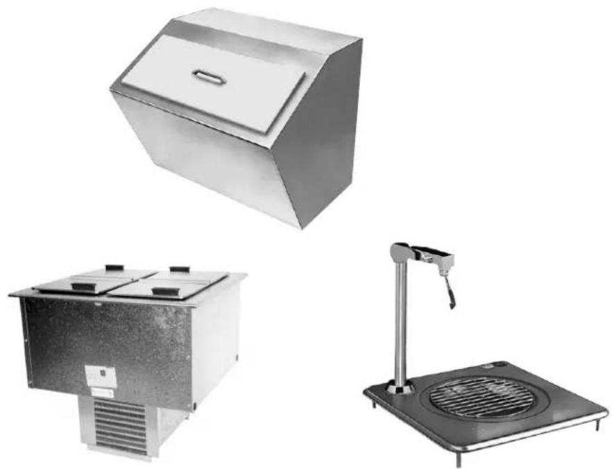
natural_image
Three industrial appliances: a large rectangular box, a two-tiered control unit with heat sinks, and a standard heating scale with a lever (no visible text or symbols)Safety Notices
▲Warning
Read this manual thoroughly before operating, installing or performing maintenance on the equipment. Failure to follow instructions in this manual can cause property damage, injury or death.
DANGER
Do not lift the condensing unit by the refrigerant tubing or other components. These features will not support the condensing unit weight. Injury and unit damage may occur!
DANGER
Do not install or operate equipment that has been misused, abused, neglected, damaged, or altered/modified from that of original manufactured specifications.
DANGER
All utility connections and fixtures must be maintained in accordance with Local and national codes.
DANGER
Keep power cord AWAY from HEATED surfaces. DO NOT immerse power cord or plug in water. DO NOT let power cord hang over edge of table or counter.
▲Warning
Authorized Service Representatives are obligated to follow industry standard safety procedures, including, but not limited to, local/national regulations for disconnection / lock out / tag out procedures for all utilities including electric, gas, water and steam.
▲Warning
This appliance is not intended for use by persons (including children) with reduced physical, sensory or mental capabilities, or lack of experience and knowledge, unless they have been given supervision concerning use of the appliance by a person responsible for their safety. Do not allow children to play with this appliance.
▲Warning
Do not store or use gasoline or other flammable vapors or liquids in the vicinity of this or any other appliance. Never use flammable oil soaked cloths or combustible cleaning solutions, for cleaning.
▲Warning
This product contains chemicals known to the State of California to cause cancer and/or birth defects or other reproductive harm. Operation, installation, and servicing of this product could expose you to airborne particles of glasswool or ceramic fibers, crystalline silica, and/or carbon monoxide. Inhalation of airborne particles of glasswool or ceramic fibers is known to the State of California to cause cancer. Inhalation of carbon monoxide is known to the State of California to cause birth defects or other reproductive harm.
▲Warning
Do not use electrical appliances or accessories other than those supplied by the manufacturer.
▲Warning
Use caution when handling metal surface edges of all equipment.
▲Warning
DO NOT touch refrigeration lines inside units; some may exceed temperatures of 200^ F ( 93.3^ C).
! Caution
Use caution handling, moving and use of the R290 refrigerators to avoid either damaging the refrigerant tubing or increasing the risk of a leak. Components shall be replaced with like components. Servicing shall be done by a factory authorized service personnel to minimize the risk of possible ignition due to incorrect parts or improper service.
Note
Proper installation, care and maintenance are essential for maximum performance and trouble-free operation of your equipment. Visit our website www.mtwkitchencare.com for manual updates, translations, or contact information for service agents in your area.
Table of Contents
Section 1 General Information
Model Numbers......4
Serial Number Location 4
Warranty Information 4
Regulatory Certifications 4
Domestic Models....4
Export Models 4
Section 2 Installation
Location 5
Clearance Requirements....6
Weight Of Equipment 6
Dimensions 6
Cutout Installation Dimension....7
N225 & N227 Standard Installation Details....8
N225 & N227 Alternate Installation Details 9
Electrical Service 10
Voltage 10
Ground Fault Circuit Interrupter 10
Rated Amperages, Horsepower, Voltage & Power Cord Chart.... 10
Refrigeration 11
Drain Connections....11
Section 3 Operation
115Volt N225P & N227P Operation 13
Temperature Control & Display 14
Changing Display from Fahrenheit to Celsius on ERC112 Control....15
230-240V Export N225-E & N227-E Operation....16
Section 4 Maintenance
Cleaning and Sanitizing Procedures....17
Interior & Exterior 17
N225 & N227 Cleaning the Condenser Coil 18
Section 1
General Information
Model Numbers
| Model Description | |
| 203 Drop-in ice chest with cover | |
| 204 | Drop-in water and ice station |
| 204P | |
| 240 Drop-in ice chest with cover | |
| 305 Drop-in ice chest with cover | |
| 307 Drop-in glass filler | |
| N225-E Drop-In Freezer with Export Voltage | |
| N225P Drop-In Freezer | |
| N227-E Drop-In Freezer with Export Voltage | |
| N227P Drop-In Freezers | |
Serial Number Location
Always have the serial number of your unit available when calling for parts or service.
| Model Serial Tag Location | |
| 203 | Bottom of the ice chest204 |
| 204P | |
| 240 On the back | |
| 305 Bottom of the ice chest | |
| 307 Underneath the top | |
| N225-E | Outside the freezer tank on the louver side |
| N225P | |
| N227-E | |
| N227P | |
Warranty Information
- Register your product for warranty,
- Verify warranty information,
• View and download a copy of your warranty, at www.delfield.com/warranty
Regulatory Certifications
DOMESTIC MODELS
All domestic models are certified by:
National Sanitation Foundation (NSF)
All domestic electrical models are certified by:

Underwriters Laboratories (UL)

• cUL Underwriters Laboratories of Canada (cUL)
EXPORT MODELS
All export models are certified by:
National Sanitation Foundation (NSF)
Export electrical models are certified by:

European Conformity

Section 2 Installation
! DANGER
Installation must comply with all applicable fire and health codes in your jurisdiction.
! DANGER
Use appropriate safety equipment during installation and servicing.
▲Warning
Remove all removable panels before lifting and installing.
▲Warning
Do not damage the refrigeration circuit when installing, maintaining or servicing the unit.
Location
▲Warning
This equipment must be positioned so that the plug is accessible unless other means for disconnection from the power supply (e.g., circuit breaker or disconnect switch) is provided.
▲Warning
Adequate means must be provided to limit the movement of this appliance without depending on or transmitting stress to the electrical conduit.
▲Warning
To avoid instability the installation area must be capable of supporting the combined weight of the equipment and product. Additionally the equipment must be level side to side and front to back.
▲Warning
This equipment is intended for indoor use only. Do not install or operate this equipment in outdoor areas.
Caution
Do not position the air intake vent near steam or heat exhaust of another appliance.
The location selected for the equipment must meet the following criteria. If any of these criteria are not met, select another location.
- Units are intended for indoor use only.
- The location MUST be level, stable and capable of supporting the weight of the equipment.
- The location MUST be free from and clear of combustible materials.
- Equipment MUST be level both front to back and side to side.
- Position the equipment so it will not tip or slide.
- Recommended air temperature is 41^ - 86^ ( 5^ - 30^ ).
- Proper air supply for ventilation is REQUIRED AND CRITICAL for safe and efficient operation. Refer to Clearance Requirements chart on page 6.
- Do not obstruct the flow of ventilation air. Make sure the air vents of the equipment are not blocked.
- Do not install the equipment directly over a drain. Steam rising up out of the drain will adversely affect operation, air circulation, and damage electrical / electronic components.
Clearance Requirements
! DANGER
Minimum clearance requirements are the same for noncombustible locations as for combustible locations. The flooring under the appliance must be made of a noncombustible material.
! DANGER
Risk of fire/shock. All minimum clearances must be maintained. Do not obstruct vents or openings.
| Condensing Unit Bottom & Sides |
| 0" (0cm) |
- Keep the vents clean and free of obstruction.
Weight Of Equipment
| Model Ship Weight | |
| 203 52lbs (24kg) | |
| 204 47.5lbs (22kg) | |
| 204P 47.5lbs (22kg) | |
| 240 36lbs (16kg) | |
| 305 18lbs (8kg) | |
| 307 7lbs (3kg) | |
| N225-EN225P | 115lbs (52kg) |
| N227-EN227P | 191lbs (87kg) |
Dimensions
| Model L D H Cabinet | Capacity | |||
| 203 20.25" (51cm) | 20.25" (51cm) | 23.25" (59cm) | 90lbs (41kg) | |
| 204 | 24" (61cm) | 21" (53cm) | 22.6" (57cm) | 45lbs (20kg) |
| 204P | 24" (61cm) | 21" (53cm) | 26.35" (67cm) | 45lbs (20kg) |
| 240 | 21" (53cm) | 17.5" (45cm) | 17" (43cm) | 75lbs (34kg) |
| 305 21.25" (54cm) | 15.25" (39cm) | 13" (33cm) | 45lbs (20kg) | |
| 307 | 12" (31cm) | 12" (31cm) | 9.5" (24cm) | — |
| N225-E | 17.06" (43cm) | 27.50" (70cm) | 26.58" (68cm) | 6 gal. |
| N225P | ||||
| N227-E | 30.58" (78cm) | 27.50" (70cm) | 26.58" (68cm) | 12 gal. |
| N227P | ||||
Cutout Installation Dimension
| Model Cutout Size | Mounting Studs | |
| 203 | 19.25" x 19.25"(49cm x 49cm) | NA |
| 204 | 21" x 17.75"(53cm x 45cm) | 4 |
| 204P | 21" x 17.75"(53cm x 45cm) | 4 |
| 240 NA NA | ||
| 305 | 12.5" x 17.75"(32cm x 45cm) | 4 |
| 307 | 9.00" x 9.00"(23cm x 23cm) | 4 |
| N225-EN225P | 16.12" x 26.62"(41cm x 68cm) | Installation details on page 8 |
| N227-EN227P | 29.62" x 26.62"(75cm x 68cm) | |
Mounting Studs
Mark the stud locations according to the measurements or place the equipment in the cutout to mark the stud locations. Drill 0.37" (1cm) diameter holes through the counter for the studs.
203 Details
When mounting a 203 ice chest into a wood counter secure it with provided clips. When mounting into a stainless steel counter, use silicone.
204 & 204P Cutout Details
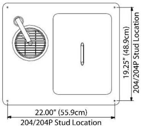
text_image
22.00" (55.9cm) 204/204P Stud Location 19.25" (48.9cm) 204/204P Stud Location240 Details
Ice chest with cover, model 240 can be set on a counter or plate shelf. Select the desired location. Mark the drain location and drill a 1.50" (4cm) diameter hole.

text_image
1.25" (3cm) Dia. OD 20.68" (55cm) 10.34" (26cm) 5.13" (73cm) 11.19" (28cm)305 Cutout Details

text_image
13.25" (33.7cm) 305 Stud Location 19.375" (49.2cm) 305 Stud Location307 Cutout Details

text_image
10.12" (25.7cm) 307 Stud Location 10.12" (25.7cm) 307 Stud LocationN225 & N227 STANDARD INSTALLATION DETAILS
For any non-standard installation consult the factory.
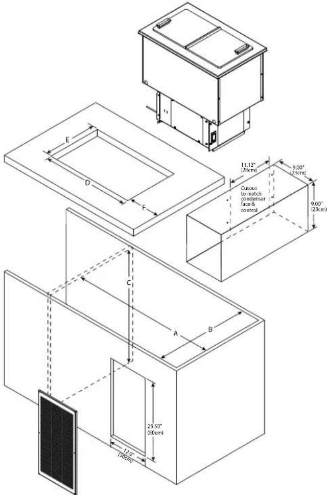
- Install a GFCI receptacle a minimum of 14" (36cm) up from the cabinet bottom inside the partitions.
- Cabinet interior minimum dimensions:
| Dimensions | N225-E, N225P | N227-E, N227P |
| A 21.50" | (55cm) 29.62" (75cm) | |
| B 29.38" | (75cm) 29.38" (75cm) | |
| C 26.00" | (66cm) 26.00" (66cm) | |
| D 16.12" | (41cm) 29.62" (75cm) | |
| E 26.62" | (68cm) 26.62" (68cm) | |
| F Minimum | 2.75" (7cm), Maximum | 7.0" (18cm) |
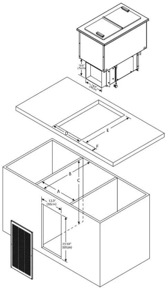
text_image
10.0° (25cm) 14.0° (30cm) D E F B C A 12.0° (30cm) 23.50° (60cm)- Place the condensing unit through the counter cutout.
- Extend the telescoping duct from the front of the condensing unit to the back of the louver. Export models do not have a telescoping duct, skip to step 6.
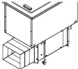
natural_image
Technical line drawing of a mechanical assembly with no visible text or symbols- Put eight provided screws through the telescoping duct side walls to hold it at the desired depth.

natural_image
Technical line drawing of a mechanical assembly with no visible text or symbolsUse Screws to Secure Desired Depth 3 of 8 Screws Shown
- Partitions must fully extend front to back and top to bottom.
- Louver cutout must extend to bottom of cabinet and align with condenser face.
NOTE: The louver provided must be installed in front of the condensing unit's finned coil. Any restriction to the proper air flow will void the compressor warranty.
- Louver measures 13.00" x 25.00" (33cm x 64cm).
- Louver Cutout Size is 12.00" x 23.50" (30cm x 60cm) (typical installation).
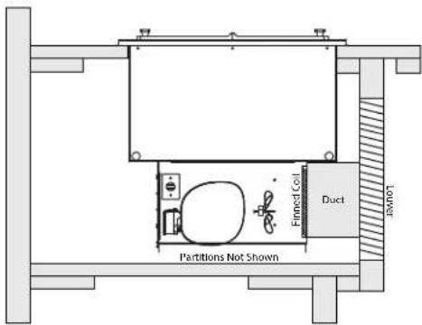
text_image
Finned Col Duct Lower Partitions Not ShownTypical Counter Cabinet
N225 & N227 ALTERNATE INSTALLATION DETAILS
NOTE: This installation is not recommended as it will limit access to the control.
| Cabinet Interior Minimum Dimensions | ||
| Dimension N | 225-E, N225P N227-E, N227P | |
| A 31.62" | (80cm) 31.62" (80cm) | |
| B 21.50" | (55cm) 29.62" (75cm) | |
| C 26.00" | (66cm) 26.00" (66cm) | |
| D 26.62" | (68cm) 26.62" (68cm) | |
| E 16.12" | (41cm) 29.62" (75cm) | |
| F Minimum 5" (13cm), Maximum 7.0" (18cm) | ||
text_image
E D F C A B 12.0" (30cm) 23.50" (60cm) Cutout to match condenser face & control 9.00" (23cm) 11.12" (28cm) 9.00" (25cm)-
Install partitions between drop-in freezer and other electrical appliances if they are located in the same cabinet. Partitions must fully extend front to back and top to bottom.
-
Install a GFCI receptacle a minimum of 14" (36cm) up from the cabinet bottom inside the partitions. Run the outlet to a switch. With limited access to the control, a switch will make it easy to turn the unit off for defrost.
-
Louver cutout must extend to bottom of cabinet.
NOTE: Any restriction to the proper air flow will void the compressor warranty.
- Louver measures 13.00" x 25.00" (33cm x 64cm).
- Louver Cutout Size is 12.00" x 23.50" (30cm x 60cm) (typical installation).
- An additional opening in cabinet to permit removal of heated air is recommended. Cut opening 8"x11", a total of 88 square inches (20cm x 28cm, a total of 568 square centimeters).
- Remove the telescoping duct from the condensing unit.
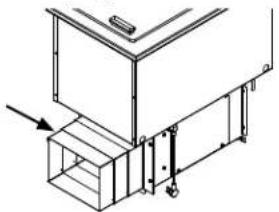
natural_image
Technical line drawing of a mechanical assembly with no visible text or symbols-
Place the condensing unit through the counter cutout.
-
Construct a 9"x9" air duct (not provided) connecting the condenser face to the louver.
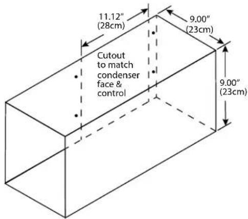
text_image
11.12" (28cm) 9.00" (23cm) Cutout to match condenser face & control 9.00" (23cm)
text_image
4 X Ø0.125" (3mm) Condenser Face 2.00" (5cm) 6.00" (15cm) 10.00" (25cm) 2.00" (5cm) 0.50" (13mm) 0.91" (23mm) 3.00" (8cm) 9.00" (23cm) 2.00" (5cm)Electrical Service
DANGER
Check all wiring connections, including factory terminals, before operation. Connections can become loose during shipment and installation.
▲Warning
This appliance must be grounded and all field wiring must conform to all applicable local and national codes. Refer to rating plate for proper voltage. It is the responsibility of the end user to provide the disconnect means to satisfy the authority having jurisdiction.
VOLTAGE
All electrical work, including wire routing and grounding, must conform to local, state and national electrical codes.
The following precautions must be observed:
• The equipment must be grounded.
- A separate fuse/circuit breaker must be provided for each unit.
- The maximum allowable voltage variation is ± 10% of the rated voltage at equipment start-up (when the electrical load is highest).
- Check all green ground screws, cables and wire connections to verify they are tight before start-up.
GROUND FAULT CIRCUIT INTERRUPTER
Ground Fault Circuit Interrupter (GFCI/GFI) protection is a system that shuts down the electric circuit (opens it) when it senses an unexpected loss of power, presumably to ground. Welbilt does not recommend the use of GFCI/GFI circuit protection to energize our equipment. If code requires the use of a GFCI/GFI then you must follow the local code. The circuit must be dedicated, sized properly and there must be a panel GFCI/GFI breaker. We do not recommend the use of GFCI/GFI outlets to energize our equipment as they are known for more intermittent nuisance trips than panel breakers.
RATED AMPERAGES, HORSEPOWER, VOLTAGE & POWER CORD CHART
| Model V/Hz/Ph Amp H.P. Plug | ||||
| 203 | N/A N/A N/A N/A | |||
| 204 | ||||
| 204P | ||||
| 240 | ||||
| 305 | ||||
| 307 | ||||
| N225-E 230 | -240/50/1 | 1.1 | 1/5 | CEE 7/7 |
| N225P 115 | /60/1 | 1.8 | 0.20 | NEMA 5-15P |
| N227-E 230 | -240/50/1 | 1.7 | 1/4 | CEE 7/7 |
| N227P 115 | /60/1 | 2.9 | 0.25 | NEMA 5-15P |
Refrigeration
| Model | Design Load BTU | System Cap. BTU | Evap BTU/ TD/Temp | Charge |
| 203 | N/A N/A | N/A | ||
| 204 | ||||
| 204P | ||||
| 240 | ||||
| 305 | ||||
| 307 | ||||
| N225-E 292 411 20/20°/-23° 6.0oz R404A | ||||
| N225P 292 411 20/20°/-23° 3.7oz R290 | ||||
| N227-E 473 532 28/19°/-22 9.0oz R404A | ||||
| N227P 473 532 28/19°/-22 4.2oz R290 | ||||
Export models are temperature class N.
Drain Connections
▲Warning
If a mechanically cooled refrigerated base does not have a condensate evaporator supplied, you must connect the condensate line to a suitable drain. Otherwise, water will collect on the floor, causing a potentially hazardous situation.
▲Warning
Moisture collecting from improper drainage can create a slippery surface on the floor and a hazard to employees. It is the owner's responsibility to provide a container or outlet for drainage.
| Model | Drain | 1/2” IPS Water Hookup |
| 203 | (1) 1” | NA |
| 204 | (2) 1” | 1 |
| 204P | (2) 1” | 1 |
| 240 | (1) 1” | NA |
| 305 | (1) 1” | NA |
| 307 | (1) 1” | 1 |
| N225-E | NA | NA |
| N225P | ||
| N227-E | ||
| N227P |
Water Connection
▲Warning
Connect to a potable water supply only.
All 1/2" (13mm) IPS water inlets must be field connected following local code requirements.
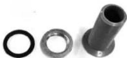
Drain
Provided 1" (25mm) drain, nut and washer must be field installed to an appropriate container or floor drain following local code requirements. Sinks come standard with 1-1/2" basket strainer assemblies.
Drain Installation Instructions
- Drain kit should include a drain, washer and nut.
- Remove/drill foam out of drain hole.
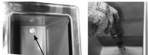
natural_image
Two black-and-white photos showing a metallic container with a small circular object and an arrow pointing to it, alongside a hand holding a tool (no visible text or symbols)-
Apply thin ring of plumbers putty around the drain.
-
From the inside drop the drain into the drain hole.
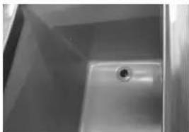
natural_image
Interior view of a simple kitchen sink with a circular drain (no text or symbols visible)- From the outside secure the drain with the washer and nut.

-
Tighten the nut with channel locks, use a fork to hold the drain in place if necessary.
-
Clean up excess plumbers putty.
THIS PAGE INTENTIONALLY LEFT BLANK
Section 3
Operation
! DANGER
The on-site supervisor is responsible for ensuring that operators are made aware of the inherent dangers of operating this equipment.
! DANGER
Do not operate any appliance with a damaged cord or plug. All repairs must be performed by a qualified service company.
! DANGER
Never stand on the unit! They are not designed to hold the weight of an adult, and may collapse or tip if misused in this manner.
▲Warning
Do not contact moving parts.
▲Warning
All covers and access panels must be in place and properly secured, before operating this equipment.
▲Warning
Damp or wet hands may stick to cold surfaces.
▲Warning
Never use sharp objects or tools to remove ice or frost. Do not use mechanical devices or other means to accelerate the defrosting process.
▲Warning
The operator of this equipment is solely responsible for ensuring safe holding temperature levels for all food items. Failure to do so could result in unsafe food products for customers.
▲Warning
Do not block the supply and return air grills or the air space around the air grills. Keep plastic wrappings, paper, labels, etc. from being airborne and lodging in the grills. Failure to keep the air grills clear will result in unsatisfactory operation of the system.
115Volt N225P & N227P Operation
The models N225P and N227P are designed to hold refrigerated or frozen product. They are set at the factory at a temperature range of -5^ F to 5^ F ( -21^ C to -15^ C). Available temperature range is -5^ F to 40^ F ( -21^ C to 4^ C).
The temperature control is located on the condensing housing.

natural_image
Technical line drawing of a mechanical enclosure or enclosure with no visible text, numbers, or symbols.Temperature Control
- At initial start-up or anytime power is disconnected, then reconnected to the unit, the control will go into normal cooling mode.
- The temperature control will cycle the compressor and condenser fan motor to maintain proper temperature.
Note
Temperature displayed is for refrigeration set point purposes only. Display does not reflect air or product temps in unit.
Defrost
Mechanically cooled freezers should be defrosted after 3/8" of ice accumulation. To defrost disconnect power to the equipment or put into stand-by mode. Never use sharp objects or tools to clean or scrape ice/frost build up from the refrigerated cold pans. A puncture could cause irreparable damage to the refrigeration system.
TEMPERATURE CONTROL & DISPLAY
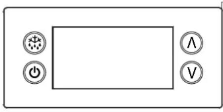
natural_image
Front view of a control panel with four labeled buttons (power, star, triangle, and voltage) arranged around a blank rectangular area (no text or symbols beyond icons)| Status Displayed Comments | |||
| Normal (°C) Temp. [°C] Unit depends on | setting (parameters in control) | ||
| Normal (°F) Temp. [°F] | |||
| Show set-point Temp. | |||
| Sensor 1 defect | E01 | X Air sensor | |
| Sensor 2 defect | E02 | X Coil sensor | |
| Sensor 3 defect | E03 | X Open | |
| Sensor 4 defect | E04 | X Open | |
| High temperature alarm | Hi | X A | Automatically switching at 2 sec rate |
| Low temperature alarm | Lo | X | |
| Line voltage too high | uHi | X | |
| Line voltage too low | uLi | X | |
| Control calls for cooling for more than 24 hours straight | LEA | X Time includes defrost. Error will go away if the control cycles off the compressor or if the power is shut off. If error is on a cold pan it could be related to a high ambient temperature or not shutting the rail off nightly. | |
Press upper or lower right button.
• Display show actual set-point (blinking).
- If buttons untouched for 3 seconds returns to normal.
- Increase set-point by pressing upper button. Max value depends on parameters in control.
- Decrease set-point by pressing lower button. Min value depends on parameters in control.
- If buttons untouched for 3 seconds returns to normal and stores new set-point.
Press lower left button for 5 seconds.
• Unit goes into stand-by mode.
• The display will read Off, then a period.
- Press the lower left button again for 5 seconds.
• The display will read On.
- The unit will then start up in normal cooling mode.
Temperature Alarm
The alarm will sound and flash HI or LO 90 minutes after the unit has reached its alarm temperature point or after any power interruption if the temperature is above or below the alarm set points.
CHANGING DISPLAY FROM FAHRENHEIT TO CELSIUS ON ERC112 CONTROL
- Simultaneously hold the up and down arrows for 5 seconds to access menu for password protected parameters.

text_image
6.01 A- Screen should temporarily flash PAS and then move to a numeric screen.
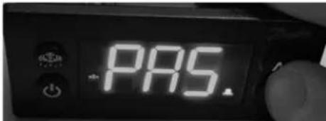
text_image
PAS.- Scroll to 187 using the up/down arrows and push the stand-by button (lower left button) to enter.

text_image
187- Scroll to dis using the up/down arrows and push the stand-by button (lower left button) to enter into the display menu.
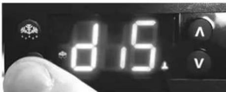
text_image
8.5- Scroll to CFu using the up/down arrows and push the stand-by button (lower left button) to enter the display unit menu.
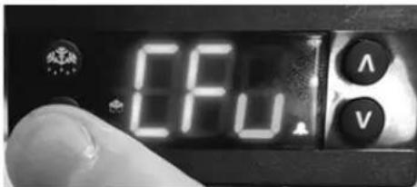
text_image
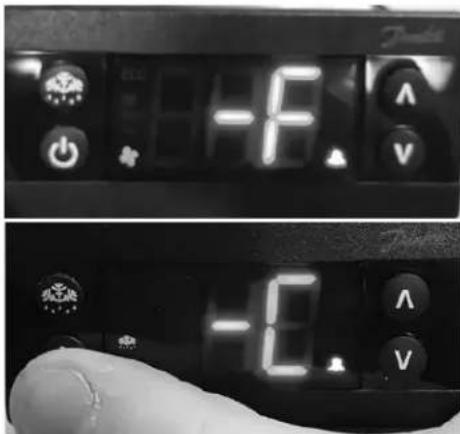
CFU A V- -F should be displayed indicating Fahrenheit. Use the down arrow to change it to -C for Celsius and hit the stand-by button (lower left button) to enter the change.
text_image
TOMATO -1.0V -1.0V- Push the defrost button (upper left button) to move out of the display unit menu.
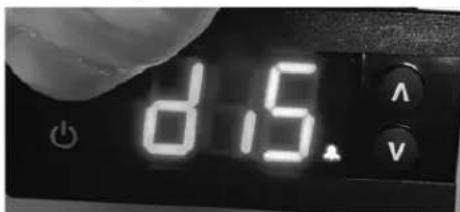
text_image
d.5. A V- Push the defrost button (upper left button) to move out of the display menu and back to the normal display.
NOTE: For steps 7 and 8, display will return back to normal display after 30 seconds of inactivity.

text_image
84.1°C V230-240V Export N225-E & N227-E Operation
The models N225-E and N227-E are designed to hold frozen products at a temperature range of 5^ F to -5^ F ( -15^ C to -21^ C). After installation, the unit will begin operating simply by plugging it into the proper outlet. If the unit does not operate after being plugged in, check to see if the thermostat is in the OFF position.
Export Defrosting
Mechanically cooled freezers should be defrosted after 3/8" of ice accumulation. To defrost disconnect power to the equipment or turn the thermostat knob to the OFF position. Never use sharp objects or tools to clean or scrape ice/frost build up from the refrigerated cold pans. A puncture could cause irreparable damage to the refrigeration system.
Section 4
Maintenance
! DANGER
It is the responsibility of the equipment owner to perform a Personal Protective Equipment Hazard Assessment to ensure adequate protection during maintenance procedures.
! DANGER
Disconnect electric power at the main power disconnect for all equipment being serviced. Observe correct polarity of incoming line voltage. Incorrect polarity can lead to erratic operation.
! DANGER
Failure to disconnect the power at the main power supply disconnect could result in serious injury or death. The power switch DOES NOT disconnect all incoming power.
▲Warning
Never use sharp objects or tools to remove ice or frost. Do not use mechanical devices or other means to accelerate the defrosting process.
| Maintenance Daily Weekly Monthly | After Prolonged Shutdown | At Start-Up | ||
| Interior & Exterior X X X | ||||
| Lid and/or Gasket X X X X | ||||
| N225 & N227 Condenser Coil | X X X |
Cleaning and Sanitizing Procedures
▲Warning
When using cleaning fluids or chemicals, rubber gloves and eye protection (and/or face shield) must be worn.
Note
Never use an acid based cleaning solution! Many food products have an acidic content, which can deteriorate the finish. Be sure to clean the stainless steel surfaces of ALL food products.
Caution
Maintenance and servicing work other than cleaning as described in this manual must be done by an authorized service personnel.
Note
When cleaning the unit, care should be taken to avoid the power cord. Keep water and/or cleaning solutions away from these parts.
Note
Never use a high-pressure water jet for cleaning or hose down or flood the units with water. Do not use power cleaning equipment, steel wool, scrapers or wire brushes on stainless steel or painted surfaces.
INTERIOR & EXTERIOR
You are responsible for maintaining the equipment in accordance with the instructions in this manual. Maintenance procedures are not covered by the warranty.
Clean the lid and the unit daily or more often to maintain cleanliness and efficient operation.
Gaskets require daily cleaning to prevent mold and mildew build up and also to retain the elasticity of the gasket. Gasket cleaning can be done with the use of warm soapy water (not citrus based cleaner). Avoid full strength cleaning products on gaskets as this can cause them to become brittle and crack. Never use sharp tools or knives to scrape or clean the gasket.
Wipe surfaces with a damp cloth rinsed in water to remove dust and dirt from the unit. Always rub with the "grain" of the stainless steel to avoid marring the finish. If a greasy residue persists, use a damp cloth rinsed in a mild dish soap and water solution. Wipe dry with a clean, soft cloth.
Never use steel wool or abrasive pads for cleaning. Never use chlorinated, citrus based or abrasive cleaners.
Stainless steel has a clear coating that is stain resistant and easy to clean. Products containing abrasives will damage the coating and scratch the panels. Daily cleaning may be followed by an application of stainless steel cleaner which will eliminate water spotting and fingerprints. Early signs of stainless steel breakdown are small pits and cracks. If this has begun, clean thoroughly and start to apply stainless steel cleaners in attempt to restore the steel.
N225 & N227 CLEANING THE CONDENSER COIL
In order to maintain proper refrigeration performance, the condenser fins must be cleaned of dust, dirt and grease regularly. It is recommended that this be done monthly. If conditions are such that the condenser is totally blocked in a month, the frequency of cleaning should be increased. Clean the condenser with a vacuum cleaner or stiff brush. If extremely dirty, a commercially available condenser cleaner may be required.
Failure to maintain a clean condenser coil can initially cause high temperatures and excessive run times. Continuous operation with a dirty or clogged condenser coil can result in compressor failure. Neglecting the condenser coil cleaning procedures will void any warranties associated with the compressor and cost to replace the compressor.

WELBILT®
Bringing innovation to the table
WWW.WELBILT.COM
Welbilt provides the world's top chefs, and premier chain operators or growing independents with industry leading equipment and solutions. Our cutting-edge designs and lean manufacturing tactics are powered by deep knowledge, operator insights, and culinary expertise.
All of our products are backed by KitchenCare ^® – our aftermarket, repair, and parts service.
▶ CLEVELAND
▶ CONVOTHERM®
DELFIELD®
▶ FITKITCHEN™
▶ FRYMASTER®
▶ GARLAND
▶ KOLPAK®
▶ LINCOLN
MANITOWOC®
▶ MERCO®
▶ MERRYCHEF®
▶ MULTIPLEX®