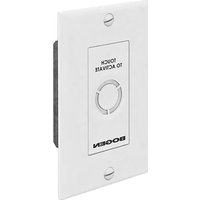
Nyquist NQ-E7020 - Intercom Bogen - Free user manual and instructions
Find the device manual for free Nyquist NQ-E7020 Bogen in PDF.


| Product Type | Digital Call Switch |
| Brand | Bogen |
| Model | Nyquist NQ-E7020 |
| Mounting | Single gang outlet box, decora wall plate |
| Interface | Capacitive touch button |
| Indicator | Multi-color LED ring (solid, blinking) |
| Power Supply | 5V DC via CAN Bus from master device |
| Communication | CAN Bus protocol |
| Connections | Screw terminals: GND, CL, CH, 5V |
| Cabling | Standard CAT5 (24 AWG solid copper recommended) |
| Max Cable Length | 600 ft (using 3-pair) for up to 24 switches |
| Daisy-Chain Capacity | Up to 68 switches (depending on cable length and pairs) |
| End-of-Line Termination | Requires load resistance on last DCS |
| Call Types | Normal, Urgent, Emergency |
| Application | Staff call initiation via Nyquist intercom system |
| Configuration | Via Nyquist system administrator (System Parameters, Class of Service) |
| LED Status Indications | Call initiation, call termination, queue cleared, individual clear |
| Compliance | Refer to administrator manual for regulatory info |
| Dimensions (approx.) | Standard decora switch size (4.5 x 2.75 x 1.5 in) |
| Operating Environment | Indoor, dry location (typical) |
Frequently Asked Questions - Nyquist NQ-E7020 Bogen
User questions about Nyquist NQ-E7020 Bogen
0 question about this device. Answer the ones you know or ask your own.
Ask a new question about this device
Download the instructions for your Intercom in PDF format for free! Find your manual Nyquist NQ-E7020 - Bogen and take your electronic device back in hand. On this page are published all the documents necessary for the use of your device. Nyquist NQ-E7020 by Bogen.
USER MANUAL Nyquist NQ-E7020 Bogen
NQ-E7020 Digital Call Switch Application Manual
The NQ-E7020 is a single gang-box style wall mounted push-button switch that allows users to initiate a normal, urgent, or emergency call from staff locations via an associated Nyquist intercom speaker.
The switch uses a capacitive touch button interface. A color LED ring is used to confirm user actions and to indicate status (for example, changing color and/or state from solid color to blinking) or to acknowledge a button press when a user initiates a call or when a call has been terminated. The LED status ring is also used to indicate when Nyquist system's call queue containing the station's call request is cleared or if the station's call request is individually cleared by the administrative station without responding.

Installation
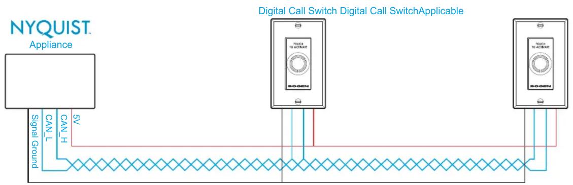
The NQ-E7020 mounts into a standard single gang outlet box and is outfitted with a standard decora plate (color based on the switch's specific application and/or customer need). The back has four screw-terminal connections (GND, CL, CH, 5V). These get connected to the matching terminals on the CAN Bus source/master device using standard CAT5 cabling. Load resistance needs to be set on the end-of-line DCS. Refer to Figure 1.
flowchart
graph LR
    A["NYQUIST Appliance"] -->|Signal Ground| B["SOGEN"]
    A -->|CAN_L| C["Digital Call Switch"]
    A -->|CAN_H| C
    A -->|5V| C
    D["Digital Call Switch Applicable"] -->|TOXIC TO ACINATE| E["SOGEN"]
    D -->|TOXIC TO ACINATE| F["SOGEN"]
    D -->|TOXIC TO ACINATE| G["SOGEN"]
    style A fill:#f9f,stroke:#333
    style D fill:#ccf,stroke:#333
    style B fill:#cfc,stroke:#333
    style F fill:#cfc,stroke:#333
    style G fill:#cfc,stroke:#333
CAN_H and CAN_L must be a twisted pair like CAT5 cabling.
CAN wiring can be daisy-chained.
All devices are internally terminated and the last switch on the bus must have the termination switch in the "ON" position.
5V and Signal Ground can be either twisted or not.
Figure 1
Recommended CAT5 Cable Lengths
CAT5 cable lengths and the number of CAT5 wire pairs determine the number of digital call switches that can be daisy-chained. (See Figure 2.)
Length limits are due to voltage drop across the power conductors. For 2-pair or 3-pair, it is best to tie the solids together and to tie the stripes together at each end of a long run. This will make it easier to keep up with which wires are V+ and V-.
| Number of CAT5 Wires to Carry 5V to Parallel Switches | |||
| 1 Pair | 2 Pair (Twisted) | 3 Pair (Twisted) | |
| CAT 5 Length (in feet) | Number of Digital Call Switches That Can Be Deployed | ||
| 600 | 8 | 16 | 24 |
| 500 | 9 | 18 | 29 |
| 400 | 12 | 24 | 35 |
| 300 | 16 | 30 | 48 |
| 200 | 24 | 48 | 68 |
Figure 2
CAUTION:
These calculations are based on standard 24 AWG solid copper wire. Calculations will not be accurate for copper-plated aluminum wire or wire guage less than 24 AWG.
Configuring
NOTE: Refer to the System Administrator Manual for detailed instructions on how to configure the DCS. DCS configuration is part of setting System Parameters and Class of Service parameters.

Brand : Bogen
Model : Nyquist NQ-E7020
Category : Intercom