
350D - Vacuum packaging Berkel - Free user manual and instructions
Find the device manual for free 350D Berkel in PDF.

| Product Type | Vacuum Packaging Machine |
| Brand | Berkel |
| Model | 350D |
| Dimensions (L x W x H) | 15.7 x 11.8 x 8.7 inches |
| Weight | 11 lbs |
| Power Supply | 120V, 60Hz, 150W |
| Sealing Bar Length | 12 inches |
| Vacuum Pump Type | Oil-free piston pump |
| Max Vacuum Pressure | -29.5 inHg |
| Functions | Vacuum sealing, marinate mode, pulse control, dry/moist food modes |
| Sealing Modes | Single seal, double seal, manual seal |
| Construction Material | Stainless steel housing with plastic controls |
| Maintenance | Wipe exterior with damp cloth; clean sealing strip with soft brush |
| Safety Features | Automatic shut-off, overheat protection, transparent lid for monitoring |
| Accessories Included | 3 vacuum bags, 1 roll bag, 1 vacuum hose, user manual |
| Spare Parts Available | Sealing strips, vacuum bags and rolls, drip tray |
| Repairability | Modular design; replaceable sealing bar and pump |
| Warranty | 2 years limited warranty |
Frequently Asked Questions - 350D Berkel
User questions about 350D Berkel
0 question about this device. Answer the ones you know or ask your own.
Ask a new question about this device
Download the instructions for your Vacuum packaging in PDF format for free! Find your manual 350D - Berkel and take your electronic device back in hand. On this page are published all the documents necessary for the use of your device. 350D by Berkel.
USER MANUAL 350D Berkel
(Models with New Vacuum Sensor and 19" Seal Bars)

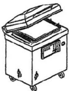
natural_image
Line drawing of a portable electronic device with open lid and control panel (no text or symbols)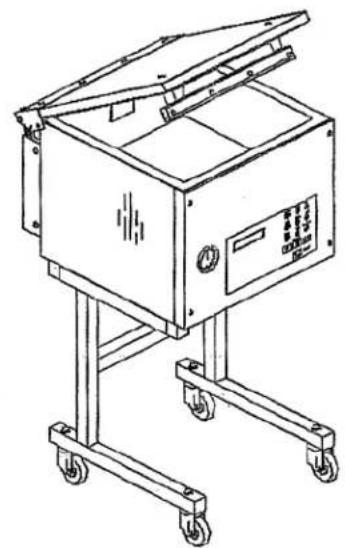
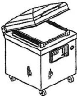
natural_image
Line drawing of a mechanical device with wheels and open lid (no text or symbols)OWNERS MANUAL
IMPORTANT SAFETY INSTRUCTIONS SAVE THESE INSTRUCTIONS

This symbol points out important safety instructions which, if not followed, could endanger the personal safety and/or property of yourself and others. Read and follow all instructions in this manual before attempting to operate your machine. Failure to comply with these instructions may result in personal injury.
General Operation
- Read, understand, and follow all instructions in the manual and on the machine before starting. Keep this manual in a safe place for further and regular reference and for ordering replacement parts.
- Only allow responsible individuals familiar with the instructions to operate the machine. Be sure to know controls and how to stop the machine quickly.
• Never put your hands near moving parts.
• Only allow qualified individuals for the maintenance of your machine.
- Remove all obstacles, which may interfere with the machine functions.
• Clear the work area such as electrical wires, buckets, knives etc.
- Be sure that everyone else is clear of your work area before operating the machine.
• Do not sit nor stand on the machine.
- Always turn off the machine after your work is done. Never leave a running machine unattended.
• Always disconnect and wait till the machine has cooled before attempting any maintenance.
- Do not wear loose fitting clothes or jewelry as they may get caught in moving parts of the machine.
- Always wear security shoes, to prevent injury caused by moving the machine or objects falling from the machine.
- Never exceed the time limit to seal, which is recommended by the manufacturer. This is to avoid any damage that may be caused to the sealing bars and to eliminate the risk of fire in the machine. Thus avoiding corporal burns.
- Never touch the sealing bars after they have been used, this will avoid corporal burns. Wait a few minutes to let the machine cool down before touching.
- Always make sure that the sealing bars are well installed in their "Guide Blocks" before starting a cycle.
- Never incline the machine more than 30 degrees, it may tip over and hurt someone seriously.
• Work only in daylight or good artificial light.
- Do not operate any appliance with a damaged cord or plug, or after the appliance malfunctions or is dropped or damaged in any manner. Return appliance to the nearest authorized service facility for examination, repair, or electrical or mechanical adjustment.
Do not operate the machine while under the influence of alcohol or drugs!
Service
- Use proper containers when draining the oil. Do not use food or beverage containers that may mislead someone into drinking from them. Properly dispose of the containers, or store in a safe place immediately following the draining of the oil.
- Prior to disposal, determine the proper method to dispose of waste from your local office of Environmental Protection Agency. Recycling centers are established to properly dispose of materials in an environmentally safe fashion.
Do not pour oil or other fluids into the ground, down a drain or into a body of water.

Warning-Your responsibility:
This machine should only be operated by personal who can read, understand and respect warnings and instructions regarding this machine in the owners manual. Save these instructions for future reference.
INSTALLATION NOTICE FOR MODELS:
250, 300, 350, 350D, 380 & 450T
IN ORDER TO RESPECT NSF REGULATIONS:
The table on which the machine has to be installed, should be of open frame type, to avoid dirt accumulation, and to allow easy cleaning under the machine.
VACUUM PACKAGING MACHINE
MODEL 350, 350D
(MC-40)
GENERAL TABLE OF CONTENTS
I OPERATION INSTRUCTIONS
II MECHANICAL
A- 350: front view assembly drawing.
B- 350: rear view assembly drawing
C- 350D: front view assembly drawing
D- 350D: rear view assembly drawing
E- 350 & 350D: front panel assembly
F- Seal bar assembly drawings (twin seal)
G- Seal bar assembly drawings (electrical bag cut option)
H-350: cover assembly drawing
I- 350D: cover assembly drawing
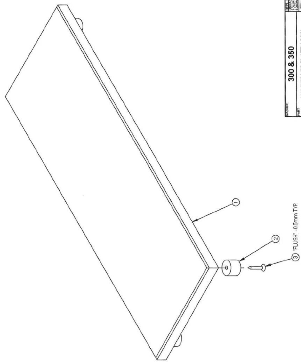
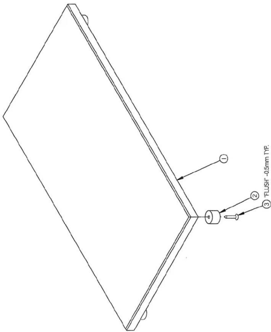
J- 350 & 350D: upper seal bar assembly drawing
K-350: gas injection kit installation drawing
L- 350D: gas injection kit installation drawing
III ELECTRICAL
A- Electrical drawings
IV PNEUMATIC
A- Pneumatic drawing
VACUUM PACKAGING MACHINES-OPERATION INSTRUCTIONS
TABLE OF CONTENTS
-
Setting up the machine
-
Electrical connection
-
Operation
3.1 Working principles
3.2 Special packaging
3.2.1 Gas flushing
3.2.2 Electrical bag cut (optional)
3.3 Vacuum packaging operation
3.3.1 Basics
3.3.2 Functions menu
3.3.2.1 Create a program
3.3.2.2 Delete a program
3.3.2.3 Select operating mode
3.3.3 Programs menu
3.3.3.1 Program identification
3.3.3.2 Vacuum time setting (sensor disabled)
3.3.3.3 Vacuum level setting (sensor enabled)
3.3.3.4 Vacuum plus time setting (sensor enabled)
3.3.3.5 Gas time setting (sensor disabled)
3.3.3.6 Gas flush level setting (sensor enabled)
3.3.3.7 Sealing time setting
3.3.4 Vacuum cycle execution
3.3.5 System monitor
3.4 Daily cleaning
- Trouble shooting
4.1 Failure during a packaging cycle
4.2 Insufficient vacuum
4.2.1 Leakage in the bag
4.2.2 No leakage in the bag
4.2.3 Insufficient vacuum in the chamber
4.3 Faulty seal
4.3.1 Insufficient seal
4.3.2 No seal
4.3.3 Permanent sealing current
4.3.4 Seal does not stick
4.4 Fault in the valves
4.5 Control board failure
- Regular maintenance
2010-08-30
VACUUM PACKAGING MACHINES
1. SETTING UP THE MACHINE:
Before choosing the site for the machine, please consider that you will also need room for packaged and non-packaged products apart from the space needed for the machine itself.
Keep in mind that the machine must not be set up upon uneven ground. Especially with mobile models, the weight of the pump might then cause warping of the machine. Then the lid will not fit correctly.
Before starting to work, check the oil view glass on the pump, if there is a sufficient quantity of oil in the pump. Never use oil other than recommended by the producer. Never exceed maximum quantity of oil indicated, when adding or changing oil. Verify weekly.
Normal ambient temperature for the vacuum pump is between 10 to 70°C. For temperature below 10°C; it is recommended to use synthetic oil. Please consult factory and pump manufacturer manual for more information or when ambient temperature are outside normal limits.
2. ELECTRICAL CONNECTION:
Electrical connections must be made by qualified personnel. This person must make sure that the electrical entries correspond to the proper voltage and amperage of the machine. GROUNDING INSTRUCTIONS: This appliance must be grounded. In the event of malfunction or breakdown, grounding provides a path of least resistance for electric current to reduce the risk of electric shock. This appliance is equipped with a cord having an equipment-grounding conductor and a grounding plug. The plug must be plugged into an appropriate outlet that is properly installed and grounded in accordance with all local codes and ordinances.
DANGER Improper connection of the equipment-grounding conductor can result in a risk of electric shock. The conductor with insulation having an outer surface that is green with or without yellow stripes is the equipment-grounding conductor. If repair or replacement of the cord or plug is necessary, do not connect the equipment-grounding conductor to a live terminal. Check with a qualified electrician or serviceman if the grounding instructions are not completely understood, or if in doubt as to whether the appliance is properly grounded. Do not modify the plug provided with the appliance if it will not fit the outlet; have a proper outlet installed by a qualified electrician.
All vacuum machines are supplied with an electrical schematic drawing. An important step in connecting the machine is to make sure that the pump turns in its correct rotation.

The pump should not rotate more than 3 to 4 seconds in the wrong rotation or it may cause serious damage. The proper rotation is indicated by an arrow on the pump motor.
3. OPERATION:
3.1 Working principles:
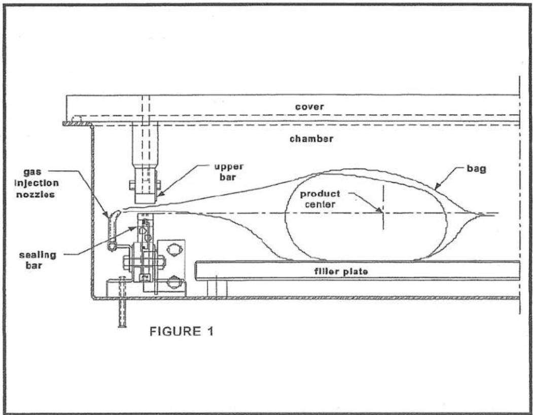
A vacuum packaging cycle is made of 3 stages. First the vacuum is made, the air is completely taken out of the chamber and from bag containing the product. (See figure 1). Then it is possible to inject neutral gas from the nozzles, if the product is delicate. Finally, a mechanism pushes the sealing bar to the rubber support to seal the bag.
To obtain nice packages, the products and the bags have to be of proportional sizes. The bag's opening should never exceed 50 cm(2") past the seal bars. The product should be centered in height in relation to the seal bar by adjusting the spacers provided.
To obtain a good seal, make sure that no residue of fat is left between the bag's inner sides where sealing is done.
3.2 Special packaging:
3.2.1 Gas flushing (option):
There is an atmospheric pressure of 1 kg/sq. cm (14 lbs/sq. inch) upon products when fully evacuated. Products which can be damaged by high pressure must be packaged with a partial vacuum, or the pressure must be counterbalance by inflating the bag with gas (nitrogen or carbon dioxide) before sealing after evacuation.
For gas flushing, the bags are placed on the sealing bars, the open end placed over the gas nozzles mounted alongside the sealing bar. After evacuation, the vacuum valve closes and the gas valve opens. Gas time (sec.) can be set in the program menu.
The necessary gas tank and pressure valve mounted on tank is not supplied, The pressure of the gas regulator should be set at approximately 1/3 kg/sq. cm (5 lbs/sq.inch.). Each machine has an adaptor for gas connection when gas flush option is ordered.
3.2.2 Electrical bag cut (optional):
This option is used to obtain a package that the excess bagtail is cut off close to the seal (cannot be used with top and bottom sealing).
3.3 Vacuum packaging operation:
Note: Refer to the menus structure on page 13 and the keyboard detail on page 14.
3.3.1 Basics:
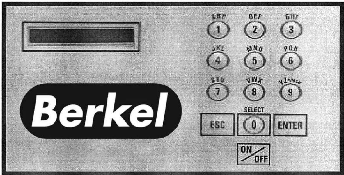
Use key "POWER" to power ON / OFF the vacuum packaging machine. When the unit is energized, the identification of the last executed program is displayed on LCD screen. To disconnect, use the "POWER" key to turn off the machine, then remove plug from outlet. Do not unplug by pulling on cord. To unplug, grasp the plug, not the cord. Unplug from outlet when not in use and before servicing or cleaning.
Use the "ESC" key to change over from the programs menu to the functions menu and from the functions menu to the programs menu.
In functions menu, use key "SELECT" to select a function and key "ENTER" to accede and executed the selection.
In programs menu, use key "SELECT" to select a program and key "ENTER" to accede and modify the selection.
In programs submenu, use key "ENTER" to pass over the parameters and point to the following one; the parameters are blinking to point out the acquisition mode. A return to programs menu is performed automatically following the last parameter acquisition.
In program submenu, use key "ESC" to get back to the programs menu. Strike any key
to clear the error messages which may be displayed on LCD screen.
3.3.2 Functions menu:
3.3.2.1 Create a program:
When executing the "create a program" function, the program submenu is acceded, starting with the identification. The initial identification "Pxx NO NAME" is given to the program and all parameters are established to zero; the program number is allocated automatically.
3.3.2.2 Delete a program:
When executing the "delete a program" function, the programs menu is acceded and the number of the first program in memory is blinking to point out the deletion mode. Use key "SELECT" to select a program and key "ENTER" to accede and confirm deletion of the selection. Use key "ESC" to unconfirm a deletion and to leave the function. When leaving the function, the number of the actual program on LCD screen cease to blink.
3.3.2.3 Select operating mode:
When executing the "select operating mode" function, which is available only for the automatic units, the actual selection is blinking to point out the acquisition mode. Use key "SELECT" to get through the operating modes, which are automatic, semi-automatic and manual; the validation of the selected operating mode is performed automatically. Use key "ESC" or "ENTER" to leave the function and get back to the program menu.
3.3.3 Programs menu:
3.3.3.1 Program identification:
For a selected program, set the identification, using the numeric keyboard characters chart; press numeric key until the desired character is selected (4 times for the numeric value). Use key "ENTER" to validate the character and to validate the characters string at the end (the new characters string is blinking). In a middle of an acquisition, use key "ESC" to come backward and erase one or several characters.
| Example: EXAMPLE 1(9 characters) | → | keys 2, 2, ENTER | → | E |
| keys 8, 8, 8, ENTER | → | X | ||
| keys 1, ENTER | → | A | ||
| keys 5, ENTER | → | M | ||
| keys 6, ENTER | → | P | ||
| keys 4, 4, 4, ENTER | → | L | ||
| keys 2, 2, ENTER | → | E | ||
| keys 9, 9, 9, ENTER | → | space | ||
| keys 1, 1, 1, 1, ENTER | → | 1 | ||
| key ENTER to validate the characters string | ||||
3.3.3.2 Vacuum time setting (sensor disabled):
For a selected program set the vacuum time, in seconds; the validation is automatically performed following the second digit entry (the new vacuum time is blinking). In a middle of an acquisition, use key "ENTER" to validate the vacuum time and key "ESC" to come backward and start over with a new acquisition (the old vacuum time is blinking).
Examples: 1s → keys 0, 1 or 1, ENTER 15s → keys 1, 5
3.3.3.3 Vacuum level setting (sensor enabled)
For a selected program set the vacuum level, starting with the values; the decimal point is automatically inserted following the second digit entry and the validation is automatically performed following the third digit entry (the new vacuum level is blinking). The vacuum level is rounded off to the nearest half value. In the middle of an acquisition, use key "ENTER" to validate the vacuum level and key "ESC" to come backward and start over with a new acquisition (the old vacuum level is blinking). Set vacuum level to zero to bypass the pressure transducer and proceed only using the vacuum plus time.
Examples: 90.0% → keys 9, 0, 0 or 9, 0, ENTER or keys 9, 0, 1 or 9, 0, 2 or 9, 0, 3 or 9, 0, 4 97.5% → keys 9, 7, 5 or keys 9, 7, 6 or 9, 0, 7 or 9, 0, 8 or 9, 0, 9 0.0% → keys 0, 0, 0 or 0, ENTER
3.3.3.4 Vacuum plus time setting (sensor enabled)
For a selected program set the vacuum plus time, in seconds; the validation is automatically performed following the second digit entry (the new vacuum plus time is blinking). In a middle of an acquisition, use key "ENTER" to validate the vacuum plus time and key "ESC" to come backward and start over with a new acquisition (the old vacuum plus time is blinking).
Examples: 1s → keys 0, 1 or 1, ENTER 15s → keys 1, 5
3.3.3.5 Gas time setting (sensor disabled)
For a selected program set the gas time setting following the same procedure as for the vacuum time. Keep in mind that increasing gas time decrease sealing pressure. Some vacuum must be kept inside to assure proper functioning.
3.3.3.6 Gas flush level setting: (sensor enabled)
For a selected program set the gas flush level following the same procedure as for the vacuum level; the maximum gas flush level setting is 10% below the vacuum setting.
3.3.3.7 Sealing time setting:
For a selected program set the sealing, starting with the seconds; the decimal point is automatically inserted following the first digit entry and the validation is automatically performed following the third digit entry (the new sealing time is blinking). The sealing time is truncated to the nearest half hundredth. In a middle of an acquisition, use key "ENTER" to validate the sealing time and key "ESC" to come backward and start over with a new acquisition (the old sealing time is blinking).
Examples: 4.50s → keys 4, 5, 0 or 4, 5, ENTER or keys 4, 5, 1 or 4, 5, 2 or 4, 5, 3 or 4, 5, 4 2.35s → keys 2, 3, 5 or keys 2, 3, 6 or 2, 3, 7 or 2, 3, 8 or 2, 3, 9 0.00s → keys 0, 0, 0 or 0, ENTER
3.3.4 Vacuum cycle execution:
For the manual units and the automatic units set on manual, close the cover to initiate a vacuum cycle. For the automatic units set on semi-automatic or on automatic, use push button "STOP / START" to initiate or interrupt a vacuum cycle. A selected program can be initiated only in the programs menu, when no modifications are in progress, and the access to the other programs and functions is denied. During cycle execution the operation status is sequentially displayed on LCD screen, except for the parameters established to zero, which are not displayed:
- Vacuum time or vacuum % status during vacuum sequence,
- Gas time or gas % status during gas flush sequence,
- Sealing time status during sealing sequence,
- ATM message during atmosphere sequence.
During cycle execution, use key "1" to abort the vacuum sequence and execute the following sequence, which is gas flush or sealing, and key "ENTER" to accede and modify the program; the parameters become valid only for the following vacuum cycles.
3.3.5 System monitor:
To accede the diagnostics menu, power up the vacuum packaging machine while keeping pushed in the "ESC" key. Use key "SELECT" to select the system monitor function and key "ENTER" to accede and visualize the monitored parameters. Use key "SELECT" to change over from the software revision, the amount of working hours done and the amount of complete cycles performed since first initialization.
-MENUS STRUCTURE-
- Functions menu:
"F1 CREATE A PRGM"
"F2 DELETE A PRGM"
"F3 SELECT OPMODE" (automatic units only)
- Programs menu:
"Pxx NAME"
Program submenu:
| "VACUUM: xx.x%" | (10.0% - 99.5%) |
| "VACUUM PLUS: xxs" | (0s - 99s) |
| "VACUUM: xx.xs" | (10 - 199s) (sensor disabled in D8 menu) |
| "GAS FLUSH: xx.xs" | (0 - 99s) (units with gas option) (sensor disabled in D8) |
| "GAS FLUSH: xx.x%" | (0.0% - 10% below the vacuum level) (units with gas option) |
| "SEAL TIME: x.xxs" | (0.00s - maximum unit allocated setting) |
| "Pxx NAME" | (12 characters) |
• Diagnostics menu (keys "ESC" & "POWER" for access):
"DIAGNOSTICS MENU" (access code required)
"D1 INPUTS TEST"
"D2 OUTPUTS TEST"
"D3 MODEL SELECT"
"D4 GAS OPTION"
"D5 SEALING TIME"
"D6 COOLING TIME"
"D7 OFFSET CALIB"
"D8 VACUUM SENSOR"
"D9 SIPROMAC PUB"
"D10 LOADING TIME" (automatic units only)
"D11 UNLOADNG TIME" (automatic units only)
"SYSTEM MONITOR" (no access code required)
"SOFTWARE: R x.xx"
"WORK HRS: xxxxx"
"CYCLES: xxxxxxx"
-KEYBOARD DETAILS-
MC-40 CONTROLS

WARNING: All electrical work described in this brochure should be done by a QUALIFIED and AUTHORIZED technician.
3.4 Daily cleaning
For hygienic cleanliness, it is imperative to clean chamber and spacers daily. Also clean the lid rubber to assure tight seat of the lid.
Cleaning instructions for gas injection nozzles: Periodically on a regular basis the gas injection nozzles must be removed with the connection tube an soaked in a food grade soap and water solution, then dried and re-installed.
4. TROUBLE SHOOTING:
4.1 Failure during packaging cycle:
4.1.1 "COVER DOWN ERROR" message is displayed on LCD(manual units):
The input signal of the down position switch has been lost during cycle execution. - Check limit switch adjustment.
4.2 Insufficient vacuum:
4.2.1 Leakage in the bag:
Most frequently, insufficient vacuum in bags is due to leakage in bag and not due to any fault of the machine.
Pin-hole leak for which there is no obvious explanation is due to faulty bag material.
Pin-hole leak caused by sharp edge of the product (bone, etc.). Use bone-guard or thicker film.
Tear in bag by careless handling (sharp edge on filling table, damage made by retailer or customer).
Leakage in lateral or bottom seal, complain to supplier of bags or film.
4.2.2 No leakage in the bag:
Bag is too large, therefore the surplus of air remains visible (there is surplus of air in 0.4% of the bag volume in each bag). Use bags of suitable size.
Vacuum time is too short:
Pressure bar is jammed and closes opening of bag during evacuation.
4.2.3 Insufficient vacuum in chamber:
If troubles described under 4.2.1 and 4.2.2 do not apply, there is something wrong with the evacuation. To find the leakage quickly, check for leaks with a precision
vacuumeter, going back step by step from the chamber to the pump.
At the chamber (measuring point at base of valve) at maximum time of evacuation. If more than 6 torr, proceed directly to the pump, if more than 3 torr: have pump service by pump supplier. If pressure at pump is good, reconnect hoses to pump and measure again.
Verify at vacuum hose connections and valve connections.
When proceeding this way, starting from pump, loss of pressure per step must not exceed 0.5 to 1 torr.
Warning: Verify connections of measuring equipment before verifying machine.
Most frequent points of leakage: lid gasket, damaged vacuum hose or loose hose clamps.
4.3 Faulty seal:
4.3.1 Insufficient seal:
Damaged teflon or silicone rubber.
Sealing pressure too low, bellows leaking or pressure bar jammed.
Leakers in seal: heating wire mechanically damaged (knicked) or silicone rubber uneven.
4.3.2 No seal:
Sealing wire burnt.
Faulty contact in sealing circuit.
Sealing transformer burnt through.
Contactor does not work.
4.3.3 Permanent sealing current:
Contactor is jammed check sealing transformer for damage through overload.
4.3.4 Seal does not stick:
Insufficient layer of polyethylene (inferior quality of bags).
Seal area extremely contaminated by fat or meat juice. Use filling aid.
Sealing temperature is too low (when using very thick films).
Warning: Do not increase sealing time more than really necessary; higher temperature will reduce working life of teflon and silicone rubber.
4.4 Fault in the valve:
Vacuum or air valve does not open.
Check whether there is voltage on the magnetic valves during their period of operation. If there is no voltage a wire is broken or the PC board is damaged.
Lid does not open at the end of the cycle; air enters, but there is still 20 - 40% vacuum in chamber. Vacuum valve does not close.
4.5 MC40 Control board failure
NOTE: Refer to menu structure on page 13.
This board software is allowing access to a "Diagnostics Menu". Only qualified service technicians are authorized to access this menu by entering a security password.
By acceding either the "D1 input test" feature or the "D2 output test" feature, a trained technician will be able to quickly know the origin of the problem: pump, sealing system, pneumatic problem, security switches problem, etc...
Keep in mind that in most cases trouble is due to a leakage, loose electrical Keynesian or evident damage to the main component: vacuum pump, valves..., electrical contactors, thermal overload, fuses holder or transformer.
For assistance do not hesitate to contact your local service technicians.
5. Regular maintenance:
Routine controls to be made at regular intervals:
Check teflon for wear.
Check silicone rubber for burnt spots and smooth even position.
Check pressure bar for jamming.
Check lid sealing for damage and hardened spots.
Check switch-point of micro switch, adjust if necessary.
Check evacuation hose for damage (contraction of diameter, or abrasions).
Check vacuum connections for tightness.
Check oil in pump (oil level in view glass; add if necessary. Regular change of oil - necessity indicated by change of color).
Check vacuum in chamber with precision vacuummeter.
Check function of cycle with various settings of timers.
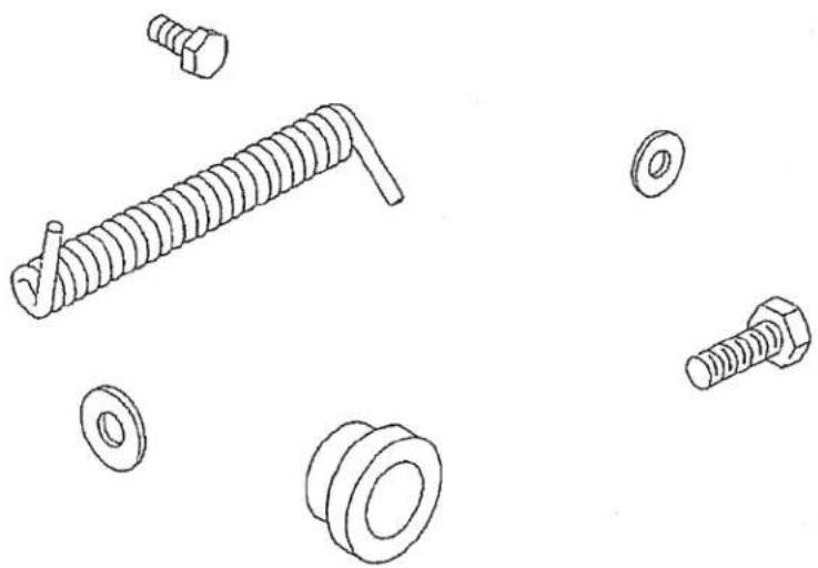
natural_image
Illustration of various bolt and nut components (no text or labels)MECHANICAL DRAWING

natural_image
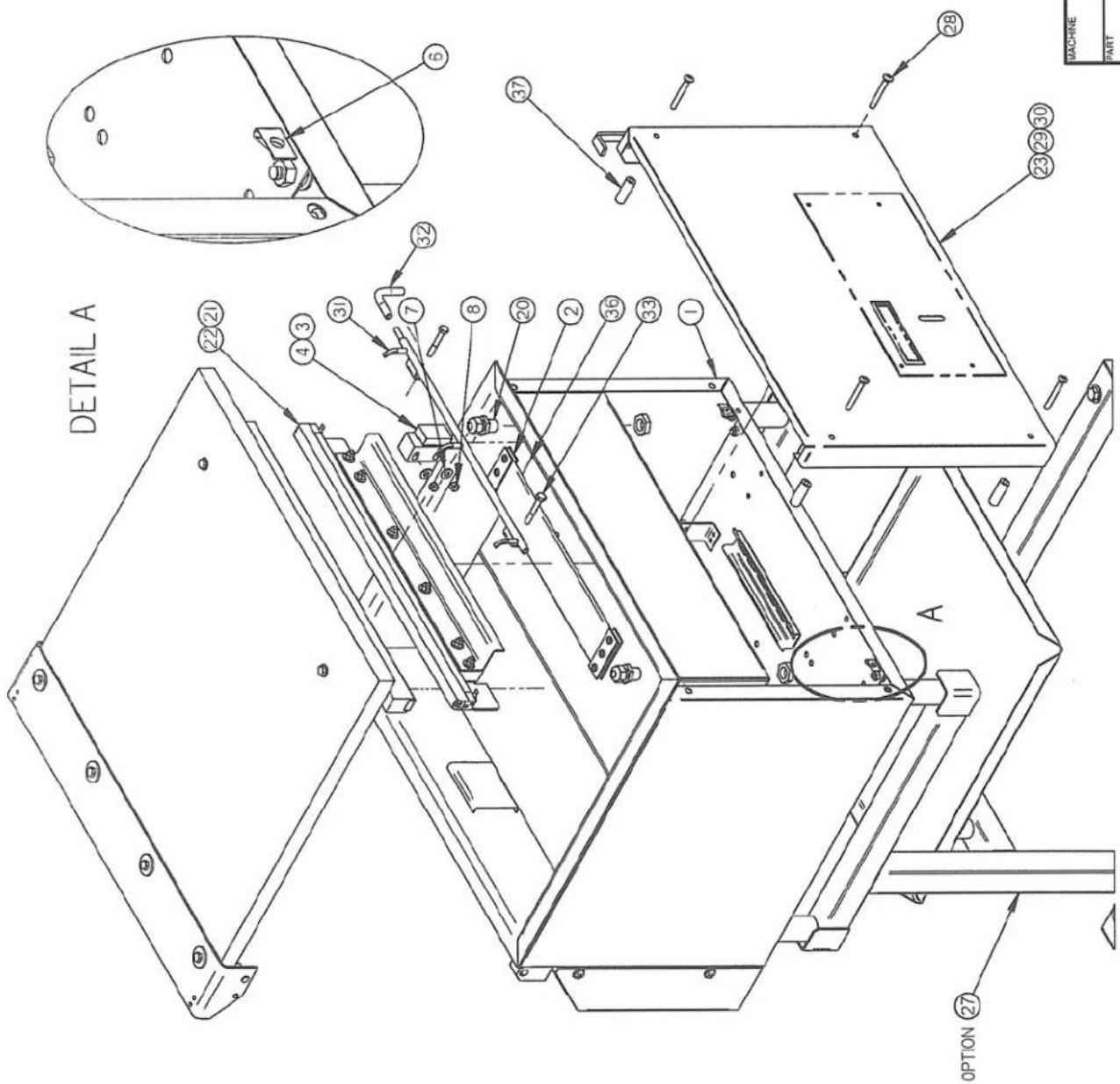
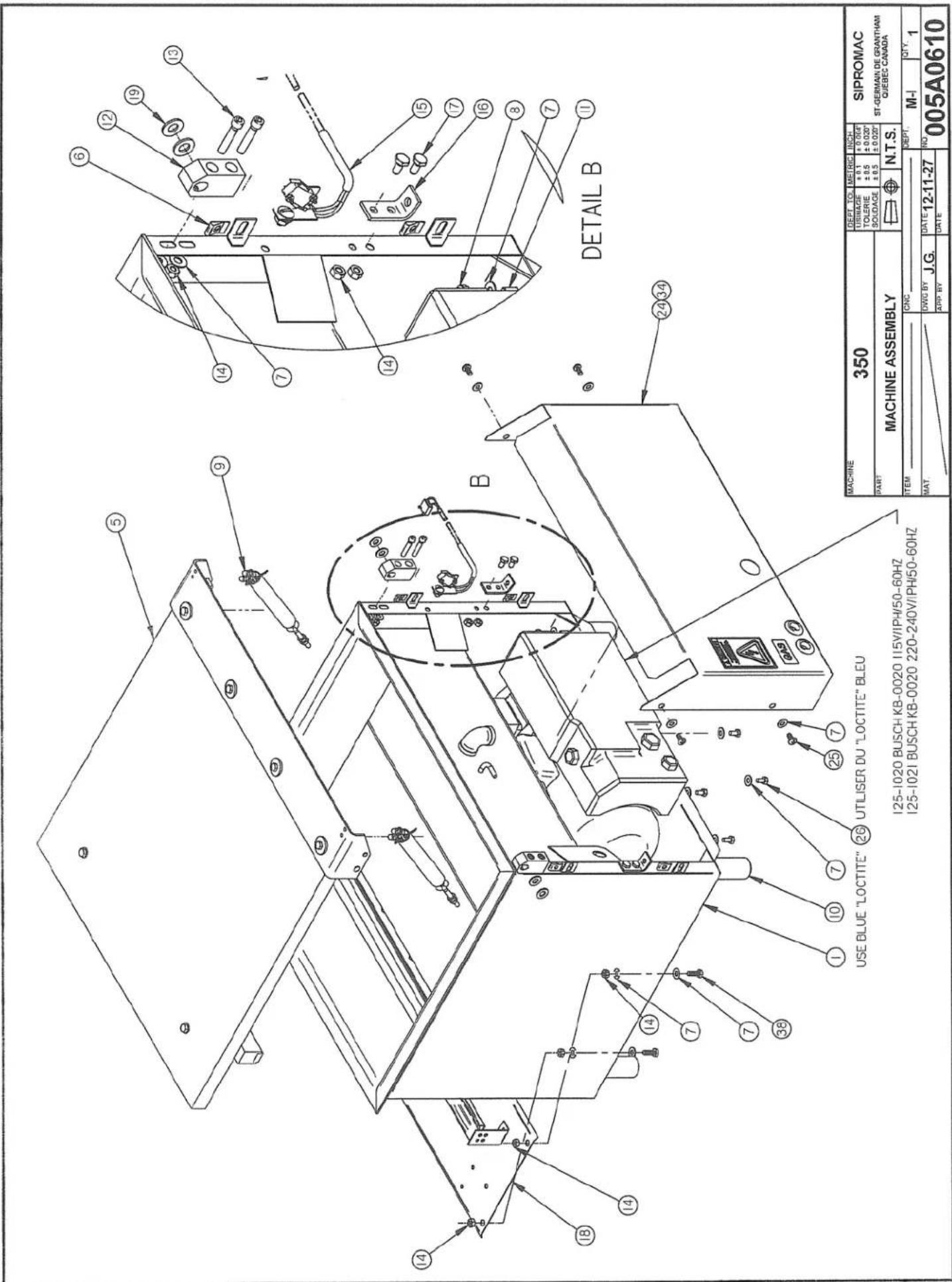
Technical line drawing of a bolt and nut assembly (no text or symbols)| ITEM | PART # | DESCRIPTION | QT. |
| 1 | 004A0229 | VACUUM PRE-ASSEMBLY | 1 |
| 2 | 005-0532 | BELLOWS ASSEMBLY | 1 |
| 3 | 002-0029 | LEFT SEAL BAR GUIDE BLOCK | 1 |
| 4 | 002-0030 | RIGHT SEAL BAR GUIDE BLOCK | 1 |
| 5 | 005A0266 | COVER ASSEMBLY | 1 |
| 6 | 056-0020 | SPRING NUT 1/4"-20 STEEL | 8 |
| 7 | 051-0740 | WASHER 1/4" FLAT S/S | 28 |
| 8 | 051-0581 | NUT 1/4"-20 NYLON LOCK S/S | 8 |
| 9 | 004A1224 | SPRING PRE-ASSEMBLY | 2 |
| 10 | 002A3528 | NSF FOOT | 4 |
| 11 | 051-0288 | BOLT 1/4-20 x 3 1/2" S/S | 4 |
| 12 | 002-0024 | HINGE BLOCK | 2 |
| 13 | 051-0232 | SCREW 1/4-20x 1-1/4"SKT CAP SS | 4 |
| 14 | 051-0580 | NUT 1/4"-20 S/S | 16 |
| 15 | 004A3374 | LIMIT SWITCH ASS'Y | 1 |
| 16 | 001-1337 | REAR SPRING SUPPORT | 2 |
| 17 | 051-0180 | BOLT. HEX. 1/4"-20 NC. x 1/2" S/S | 4 |
| 18 | 004-0042 | ELEC. SUPPORT PRE-ASS'Y | 1 |
| 19 | 058-0030 | NYLON SPACER 3/8IDx3/4ODx1/16 | 4 |
| 20 | 036-0400 | WIRE CONNECT. 3/8" NPT CD09/O-RING/NUT | 2 |
| 21 | 005A1356 | SEAL BAR ASSEMBLY W/SUPP. BAG CUT | 1 |
| 22 | 005A1355 | SEAL BAR ASSEMBLY W/SUPP. TWIN SEAL | 1 |
| 23 | 005C0832 | FRONT PANEL ASS'Y W/VAC SEN (SI) | 1 |
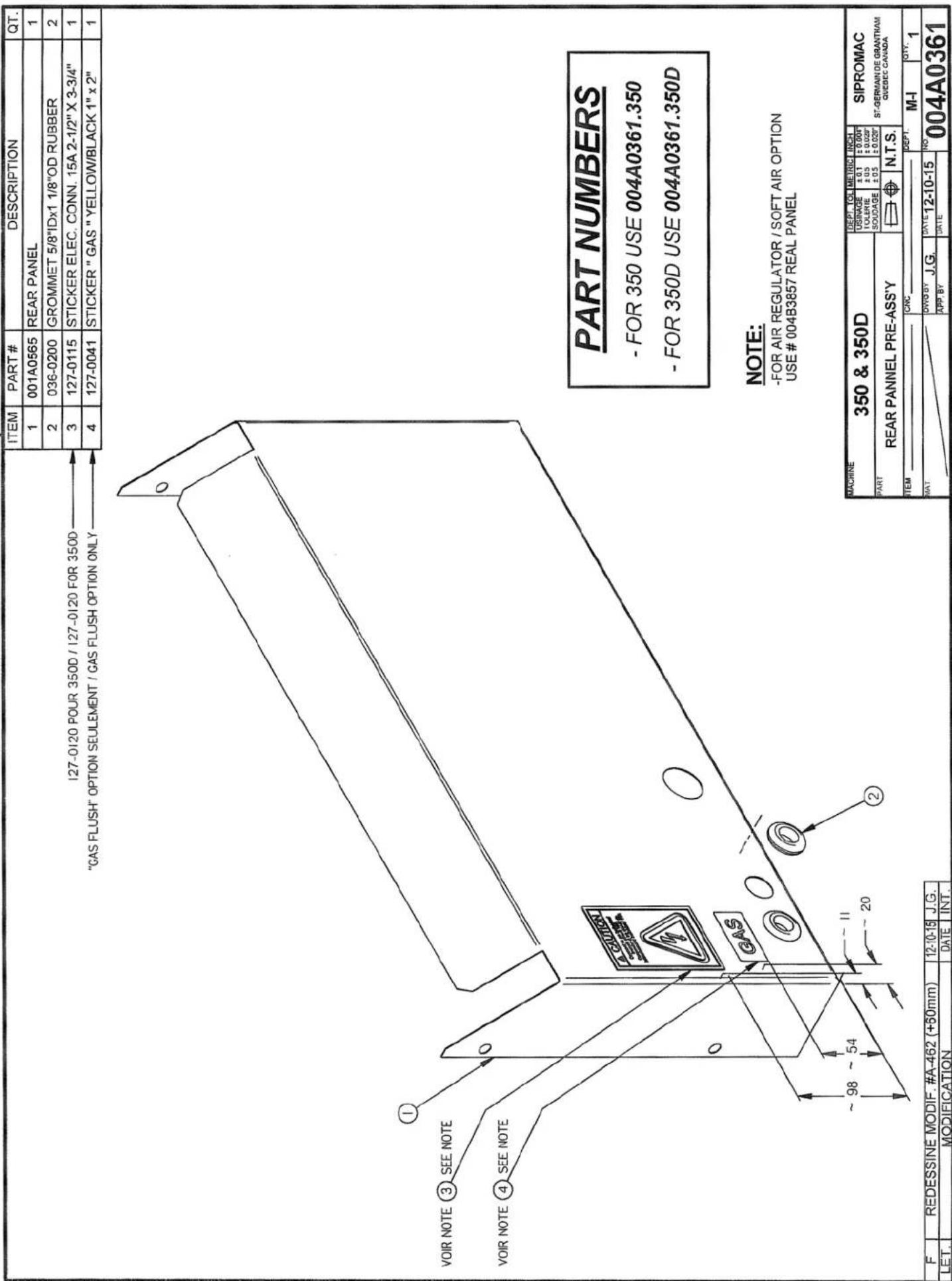
| 24 | 004A0361 | REAR PANNEL PRE-ASS'Y | 1 |
| 25 | 051-0185 | SCREW 1/4-20x 1/2"PAN PHIL S/S | 4 |
| 26 | 051-0930 | BOLT M6 x 10 S/S | 4 |
| 27 | 005B1031 | STAND ASSEMBLY (OPTION) | 1 |
| 28 | 051-0264 | SCREW 1/4-20x 2"PAN PHIL SS | 4 |
| 29 | 005B1341 | FRONT PANEL ASS'Y W/VAC SEN (BK) | 1 |
| 30 | 005B1339 | FRONT PANEL ASS'Y W/VAC SEN (BSA) | 1 |
| 31 | 005A0533 | LEFT GAS INJECTION BAR ASSEMBLY | 1 |
| 32 | 104-0064 | SURGERY TUBE 3/8"OD x 3/16"ID x 90 | 2 |
| 33 | 051-0255 | BOLT 1/4-20 x 1-3/4" HEX SS | 2 |
| 34 | 004B3857 | REAR PANNEL PRE-ASS'Y | 1 |
| 35 | 005A0278 | FILLER PLATE ASS'Y | 1 |
| 36 | 005A0364 | HALF FILLER PLATE ASS'Y | 2 |
| 37 | 003A0370 | PANEL SPACER | 4 |
| 38 | 051-0190 | BOLT 1/4-20 x 3/4" HEX S/S | 4 |
| MACHINE 350 | DEPT. TOL METRIC | INCH | SIPROMAC ST-GERMAIN DE GRANTHAM QUEBEG CANADA | ||||
| USINAGE TOLERIE SOUDAGE | ±0.1 ±0.5 ±0.5 | ±0.004 ±0.020° | |||||
| PART MACHINE ASSEMBLY | ±0.020° | ||||||
| N.T.S. | |||||||
| ITEM | CNC | DEPT. | M-I | QTY. | |||
| MAT. | DWG BY J.G. | DATE 12-11-27 | NO 005A0610 | ||||
| APP BY | DATE | ||||||
| MACHINE 350 | DEPT. TO. | METRIC | INCH | SIPROMAC ST-GERMAIN DE GRANTHAM QUEBEC CANADA | ||
| USIAGE TOLERIE SOLIDAGE | ±0.1 ±0.5 ±0.5 | ±0.004° ±0.020° ±0.020° | ||||
| PART MACHINE ASSEMBLY | ||||||
| N.T.S. | ||||||
| ITEM | CNC | DEPT. M-I | QTY. 1 | |||
| MAT. | DWG BY J.G. | DATE 12-11-27 | NO. 005A0610 | |||
| APP BY | DATE | |||||
125-1020 BUSCH KB-0020 115V/IPH/50-60HZ 125-1021 BUSCH KB-0020 220-240V/IPH/50-60HZ
| ITEM | PART # | DESCRIPTION | QT. |
| 1 | 004A0230 | VACUUM PRE-ASSEMBLY | 1 |
| 2 | 005-0532 | BELLOWS ASSEMBLY | 1 |
| 3 | 002-0029 | LEFT SEAL BAR GUIDE BLOCK | 2 |
| 4 | 002-0030 | RIGHT SEAL BAR GUIDE BLOCK | 2 |
| 5 | 005A0481 | COVER ASSEMBLY | 1 |
| 6 | 056-0020 | SPRING NUT 1/4"-20 STEEL | 8 |
| 7 | 051-0740 | WASHER 1/4" FLAT S/S | 32 |
| 8 | 051-0581 | NUT 1/4"-20 NYLON LOCK S/S | 12 |
| 9 | 004A1224 | SPRING PRE-ASSEMBLY | 2 |
| 10 | 002A3528 | NSF FOOT | 4 |
| 11 | 051-0288 | BOLT 1/4-20 x 3 1/2" S/S | 4 |
| 12 | 002-0024 | HINGE BLOCK | 2 |
| 13 | 051-0232 | SCREW 1/4-20x 1-1/4"SKT CAP SS | 4 |
| 14 | 051-0580 | NUT 1/4"-20 S/S | 16 |
| 15 | 004A3374 | LIMIT SWITCH ASS'Y | 1 |
| 16 | 001-1337 | REAR SPRING SUPPORT | 2 |
| 17 | 051-0180 | BOLT. HEX. 1/4"-20 NC. x 1/2" S/S | 4 |
| 18 | 004-0042 | ELEC. SUPPORT PRE-ASS'Y | 1 |
| 19 | 058-0030 | NYLON SPACER 3/8IDx3/4ODx1/16 | 4 |
| 20 | 036-0400 | WIRE CONNECT. 3/8" NPT CD09/O-RING/NUT | 4 |
| 21 | 005A1356 | SEAL BAR ASSEMBLY W/SUPP. BAG CUT | 2 |
| 22 | 005A1355 | SEAL BAR ASSEMBLY W/SUPP. TWIN SEAL | 2 |
| 23 | 005C0832 | FRONT PANEL ASS'Y W/VAC SEN (SI) | 1 |
| 24 | 004A0361 | REAR PANNEL PRE-ASS'Y | 1 |
| 25 | 051-0185 | SCREW 1/4-20x 1/2"PAN PHIL S/S | 4 |
| 26 | 051-0930 | BOLT M6 x 10 S/S | 4 |
| 27 | 005B1031 | STAND ASSEMBLY (OPTION) | 1 |
| 28 | 051-0264 | SCREW 1/4-20x 2"PAN PHIL SS | 4 |
| 29 | 005A0365 | FILLER PLATE ASS'Y | 2 |
| 30 | 005B1341 | FRONT PANEL ASS'Y W/VAC SEN (BK) | 1 |
| 31 | 005B1339 | FRONT PANEL ASS'Y W/VAC SEN (BSA) | 1 |
| 32 | 005A0533 | LEFT GAS INJECTION BAR ASSEMBLY | 1 |
| 33 | 005A0808 | RIGHT GAS INJECTION BAR ASSEMBLY | 1 |
| 34 | 104-0064 | SURGERY TUBE 3/8"OD x 3/16"ID x 90 | 2 |
| 35 | 051-0255 | BOLT 1/4-20 x 1-3/4" HEX SS | 4 |
| 36 | 004B3857 | REAR PANNEL PRE-ASS'Y | 1 |
| 37 | 003A0370 | PANEL SPACER | 4 |
| 38 | 051-0190 | BOLT 1/4-20 x 3/4" HEX S/S | 4 |
| MACHINE 350D | DEPT. TOL | METRIC | INCH. | SIPROMAC ST-GERMAIN DE GRANTHAM QUEBEC CANADA | |||
| USINAGE | ±0.1 | ±0.00" | |||||
| TOLERIE | ±0.05 | ±0.020" | |||||
| SOUDAGE | ±0.05 | ±0.026" | |||||
| PART MACHINE ASSEMBLY | N.T.S. | ||||||
| ITEM | CNC | DEPT. | M-I | QTY. | |||
| MAT. | DWG BY J.G. | DATE 12-11-27 | NO 005A0611 | ||||
| APP. BY | DATE | ||||||


| MACHINE 350D | DEPT. TOL. METRIC INCH | SIPROMAC ST-GERMAIN DE GRANTHAM QUEBEG CANADA | ||||
| USINAGE ±0.1 TOLERIE ±0.5 SOUDAGE ±0.5 | ±0.064 ±0.020' ±0.020' | |||||
| PART MACHINE ASSEMBLY | ||||||
| N.T.S. | ||||||
| ITEM | CNC | DEPT. M-I QTY. 1 | ||||
| MAT. | DWG BY J.G. | DATE 12-11-27 | NO 005A0611 | |||
| APP. BY | DATE | |||||
| ITEM | PART # | DESCRIPTION | QT. |
| 1 | 001-0944 | SUPPORT SWITCH | 1 |
| 2 | 051-01865 | SCREW 1/4"-20 NC. X 1/2" TRUSS SLOT S/S | 1 |
| 3 | 051-0740 | FLAT WASHER 1/4"∅ S/S | 1 |
| 4 | 051-0580 | HEX. NUT 1/4"-20 NC. S/S | 1 |
| 5 | 051-0080 | SCREW #4-40 X 5/8" PAN SLOT S/S | 2 |
| 6 | 051-0715 | WASHER #4 LOCK S/S | 2 |
| 7 | 051-0540 | NUT #4-40 S/S | 2 |

| G | A&R 300 & 300D SEE 004A3374 / 030-0631 WAS 030-0610 | 10-11-16 | D.A. | MACHINE250, 350, 350D, 380 & 380T | METRIC TOLERANCEQ. ± .5.0 ± .05.00 ± .005.000 ± .0005°N.T.S. | INCH TOLERANCE.0 ± .015".00 ± .005".000 ± .0005" | SIPROMACST-GERMAIN DE GRANTHAM, QUEBEC CANADA | |||
| F | #2 051-01865 TRUSS SLOT WAS 051-0180 HEX | 10-11-10 | D.A. | |||||||
| E | AJOUTER 300D | 06-05-24 | M.A.L. | PARTLIMIT SWITCH ASSEMBLY | ||||||
| D | AJOUTER 380T | 06-01-26 | M.A.L. | |||||||
| C | AJOUTER 380 | 03-02-12 | Y.C. | ITEM: ____ | CNC: ____ | DEPT. M-I | QT. 1 | |||
| B | ADDED 300 | 98-05-22 | D.A. | |||||||
| A | REDRAWN | 97-11-11 | M.L. | MAT:____/____ | DWC BY M.LAVIGNEAPP. | DATE 97-11-11 | NO.004-0261 | |||
| LET. | MODIFICATION | DATE | INT. | DATE | ||||||
|004A1224
| ITEM | PART # | DESCRIPTION | QT. |
| 1 | 009A0152 | SPRING BLACK | 1 |
| 2 | 056-0150 | EYE BOLT 1/4"-20 x 3" ZINC | 1 |
| 3 | 051-0580 | NUT 1/4"-20 S/S | 2 |
| 4 | 056-2500 | U-BOLT CABLE CLAMP THRD #10-24 | 1 |
| 5 | 051-0570 | NUT #10-24 ACORN SS | 2 |
| 6 | 008A1603 | SPRING PROTECTION TUBE | 1 |
| 7 | 056-0118 | COTTER PIN 3/32" x 1" S/S | 1 |

| E | AJOUTER ITEM 008A1603 & 056-0118 (NSF) | 10-11-09 | J.G. |
| D | ADDED ITEM #3 051-0580 QTY : 2 | 05-05-05 | M.A. |
| C | ADDED 380T | 05-02-03 | M.A. |
| B | 009A0152 WAS 077-0002 | 04-12-07 | M.A. |
| A | AJOUTER 380 DANS CARTOUCHE | 03-09-04 | J.P. |
| LET. | MODIFICATION | DATE | INT. |
| 380T | 4 |
| 380 | 2 |
| 350D | 2 |
| 350 | 2 |
| 300 | 2 |
| MACHINE | QTY |
| MACHINE 300, 350, 350D 380 & 380T | DEPT. TOI METRIC INCH | SIPROMAC ST-GERMAIN DE GRANTHAM QUEBEC CANADA | ||||
| USINAGE TOLERIE SOLDAGE | ±0.1 ±0.5 ±0.5 | ±0.004' ±0.020' ±0.020' | ||||
| PART SPRING PRE-ASSEMBLY | N.T.S. | |||||
| ITEM | CNC | DEPY. M-(M) | QTY LISTE | |||
| MAT. | DWG BY L.T. | DATE 03-02-17 | NO. 004A1224 | |||
| APP. BY | DATE 16-11-U | |||||

| ITEM | PART # | DESCRIPTION | QT. |
| 1 | 033-0015 | MC-40 KEYBOARD "SIPROMAC" | 1 |
| 2 | 001C3123 | FRONT FLAT PANEL | 1 |
| 3 | 051-0092 | SCREW #4-40 x 1 1/4" FLAT SLT S/S | 4 |
| 4 | 051-0720 | WASHER #8 FLAT S/S | 4 |
| 5 | 058-0120 | CPVC SPACER 0.120" x 1/4" x 5/8" | 4 |
| 6 | 051-0540 | NUT #4-40 HEX S/S | 8 |
| 7 | 033-0038 | MC-40 SENSOR VACUUM | 1 |
| 8 | 051-0715 | WASHER #4 LOCK SS | 4 |
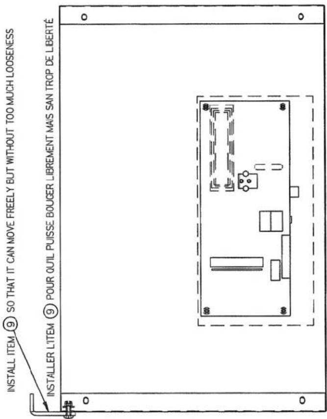
| 9 | 004A1651 | COVER HOLD DOWN PRE-ASS'Y | 1 |

natural_image
Line drawing of a rectangular metal frame with two recessed panels and mounting brackets (no text or symbols)-VACUUM SENSOR OPTION-
-SIPROMAC OPTION -
| MACHINE 350 & 350D | DEPT. TOL METRIC | INCH | SIPROMAC ST-GERMAIN DE GRANTHAM QUEBEC CANADA | |||
| USIAGE ±0.1 TOLERIE ±0.5 Soudage ±0.5 | ±0.004' ±0.020' ±0.020' | |||||
| PART FRONT PANEL ASS'Y W/VAC SEN (SI) | N.T.S. | |||||
| ITEM | CNC | DEPT. M-(I) | QTY. 1 | |||
| MAT. | DWG BY J.G. | DATE 12-10-15 | NO 005C0832 | |||
| APP BY | DATE | |||||

| ITEM | PART # | DESCRIPTION | QT. |
| 1 | 033-0018 | MC-40 KEYBOARD "BERKEL" | 1 |
| 2 | 001C3123 | FRONT FLAT PANEL | 1 |
| 3 | 051-0092 | SCREW #4-40 x 1 1/4" FLAT SLT S/S | 4 |
| 4 | 051-0720 | WASHER #8 FLAT S/S | 4 |
| 5 | 058-0120 | CPVC SPACER 0.120" x 1/4" x 5/8" | 4 |
| 6 | 051-0540 | NUT #4-40 HEX S/S | 8 |
| 7 | 033-0038 | MC-40 SENSOR VACUUM | 1 |
| 8 | 051-0715 | WASHER #4 LOCK SS | 4 |
| 9 | 004A1651 | COVER HOLD DOWN PRE-ASS'Y | 1 |
natural_image
Technical line drawing of a rectangular frame with two internal compartments and mounting holes (no text or symbols)-VACUUM SENSOR OPTION-
-BERKEL OPTION -
| MACHINE350 & 350D | DEPT. TCL METRIC INCH | SIPROMACST-GERMAIN DE GRANTHAMQUEBEC CANADA | |||
| USNAGE TOLERIESOUDAGE ±0.1±0.5±0.5 ±0.020° | |||||
| PARTFRONT PANEL ASS'Y W/VAC SEN (BK) | N.T.S. | ||||
| ITEM | CNC | DEPT.M-(M)-I CTV.1 | |||
| MAT | DWG BY J.G. | DATE 12-10-15 | NO.005B1341 | ||
| APP BY | DATE | ||||

| ITEM | PART # | DESCRIPTION | QT. |
| 1 | 033-0019 | MC-40 KEYBOARD "BSA" | 1 |
| 2 | 001C3123 | FRONT FLAT PANEL | 1 |
| 3 | 051-0092 | SCREW #4-40 x 1 1/4" FLAT SLT S/S | 4 |
| 4 | 051-0720 | WASHER #8 FLAT S/S | 4 |
| 5 | 058-0120 | CPVC SPACER 0.120" x 1/4" x 5/8" | 4 |
| 6 | 051-0540 | NUT #4-40 HEX S/S | 8 |
| 7 | 033-0038 | MC-40 SENSOR VACUUM | 1 |
| 8 | 051-0715 | WASHER #4 LOCK SS | 4 |
| 9 | 004A1651 | COVER HOLD DOWN PRE-ASS'Y | 1 |

natural_image
Line drawing of a rectangular metal frame with a recessed door and mounting bracket (no text or symbols)-VACUUM SENSOR OPTION-
-BSA OPTION -
| MACHINE 350 & 350D | DEPT. TOL METRIC | INCH | SIPROMAC ST-GERMAIN DE GRANTHAM QUEBEC CANADA | ||||
| USINAGE TOLERIE SOUAGE | ±0.1 ±0.5 ±0.5 | ±0.00" ±0.020" | |||||
| PART FRONT PANEL ASS'Y W/VAC SEN (BSA) | N.T.S. | ||||||
| ITEM | CNC | DEPT. M-(M)-I | QTY. 1 | ||||
| MAT. | DWG BY J.G. | DATE 12-10-15 | NO. 005B1339 | ||||
| APP BY | DATE | ||||||

004-0346
| ITEM | PART # | DESCRIPTION | QT. |
| 1 | 125-1020 | BUSH PUMP KB-20 /115V/1PH/60HZ | 1 |
| 2 | 101-0220 | STRAIGHT 1⁄2"MNPTx3/4" HOSE BARB BRASS | 1 |
| 3 | 051-0740 | WASHER 1/4" FLAT S/S | 4 |
| 4 | 051-0950 | BOLT M6 x 16 SS | 4 |

| MACHINE 350, 350D, 380 & 380T | DEPT. TOL | METRIC | INCH | SIPROMAC ST-GERMAIN DE GRANTHAN QUEBEC CANADA | |
| UBINAGE | ±0.1 | ±0.004" | |||
| TOLERIE | ±0.5 | ±0.020" | |||
| PART "BUSCH" PUMP INSTALATION | SOUDAGE | ±0.5 | ±0.020" | ||
| N.T.S. | |||||
| ITEM | CNC | DEPT. M | QTY. 1 | ||
| MAT. | DWG BY L.T. | DATE 02-03-11 | NO. 004-0346 | ||
| APP. BY | DATE 06-01-30 | ||||
A ADDED 380T 05-01-26 M.A. LET. MODIFICATION DATE INT.
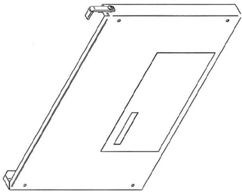
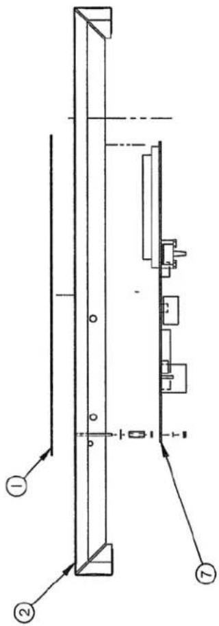
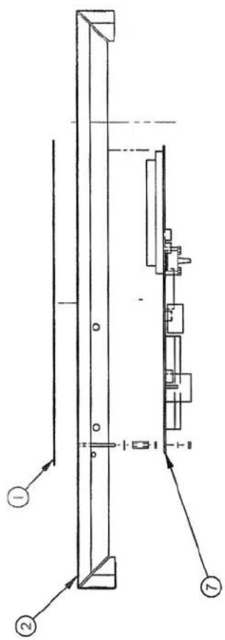
| ITEM | PART # | DESCRIPTION | QT. |
| 1 | 004-0352 | SEAL BAR PRE-ASSEMBLY | 1 |
| 2 | 002-0512 | SEAL BAR SUPPORT | 1 |
| 3 | 051-0256 | BOLT 1/4"-20nc. X 1 3/4" CAP SKT S/S | 3 |
| 4 | 001-1960 | EXTERIOR BELLOWS COVER | 1 |
| 5 | 001-1856 | EXTERIOR BELLOWS COVER | 1 |
| 6 | 001A6229 | SEAL BAR GUIDE | 2 |
| 7 | 051-0740 | WASHER 1/4" FLAT S/S | 10 |
| 8 | 051-0250 | BOLT 1⁄4"-20nc. X 11⁄2" S/S | 4 |
| 9 | 051-0581 | NUT 1/4"-20 NYLON LOCK S/S | 6 |
| 10 | 051-0230 | HEX BOLT 1/4-20 x 1 1/4" SS | 2 |
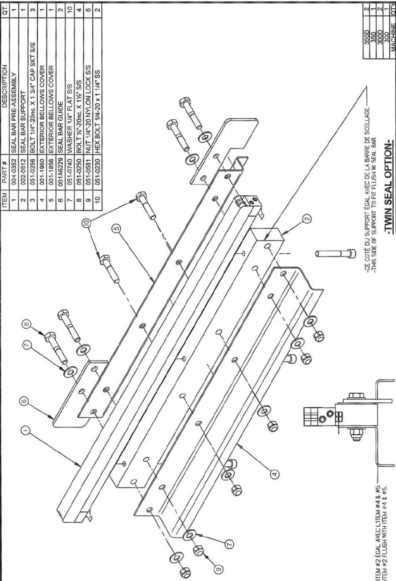
-END VIEW-
-CE COTÉ DU SUPPORT ÉGAL AVEC DE LA BARRE DE SCELLAGE
-THIS SIDE OF SUPPORT TO FIT FLUSH W/ SEAL BAR.
| MACHINE300, 300D, 350 & 350D | DEPT. TOL METRIC INCH | SIPROMACST-GERMAIN DE GRANTHAMQUEBEC CANADA | ||||
| USINAGETOLERIE SOUDAGE ±0.1±0.5±0.5±0.207±0.207 | ||||||
| PARTSEAL BAR ASSEMBLY W/SUPPORT | N.T.S. | |||||
| ITEM | CNC | DEPT.M-I-(M) QTY LIST | ||||
| MAT. | DWG BY J.G. | DATE 12-09-24 | NO005A1355 | |||
| APP BY | DATE | |||||
A REDESSINE ETAIT 005B0046 12-09-24 J.G. LET. MODIFICATION DATE INT.
| ITEM | #PART | DESCRIPTION | QT. |
| 1 | 002-0481 | SEAL BAR (TABLE) | 1 |
| 2 | 002-0031 | CONNECTOR | 2 |
| 3 | 039-0200 | SEALING ELEM. STD TWIN (2x626mm EA.) | 4.31 |
| 4 | 052-0395 | SCREW 1/4"-20 NC. X 5/16" SET HEX SKT OVAL PT | 4 |
| 5 | 052-0250 | SCREW #8-32 X 1 1/2" RND SLOT BRASS | 2 |
| 6 | 051-0550 | NUT #8-32 S/S | 4 |
| 7 | 176-0200 | TEFLON TAPE 5S ADHESIVE X 2" X (496mm EA.) | 0.063 |
| 8 | 027-0400 | CONNECTOR ADAPTOR 1/4" X #10 STUD | 2 |
| 450T | 2 |
| 450A | 2 |
| 400 | 2 |
| 3500 | 2 |
| 350 | 1 |
| 3000 | 2 |
| 300 | 1 |
| MACHINE | QTÉ. |
| MACHINE VOIR LISTE | TOLERANCE RETERG INCH | SIPROMAC ST-GERMAIN DE GRANTHAM QUEBEC CANADA | ||||
| USINAGE ± 0.1 TOLERE ± 0.5 SoudAGE ± 0.5 N.T.S. | ||||||
| PART: SEAL BAR PRE-ASSEMBLY | ||||||
| ITEM: | CNC: | DEPT.M-1 | OT.2 | |||
| MAT: | DWG A.P. APP. | DATE 98-02-10 | NO. 004-0352 | |||
| F | ADDED 300, 300D, 350 & 350D WAS 005-0267 | 12-09-24 | J.G. |
| E | ADDED 450T WAS 005-0377 | 08-05-26 | D.A. |
| D | MODIFICATION #A-0398 (CONNECTEUR) | 04-04-19 | J.G. |
| C | ADDED 400 | 99-05-06 | S.L. |
| B | REDRAWN | 98-02-10 | A.P. |
| LET. | MODIFICATION | DATE | INT. |
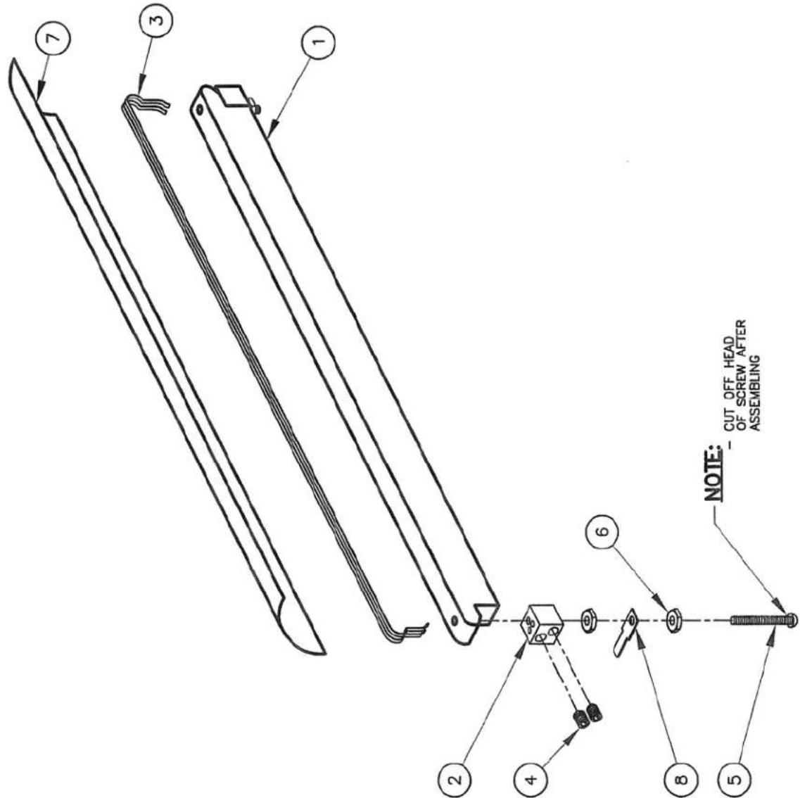
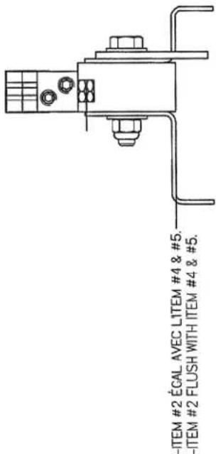
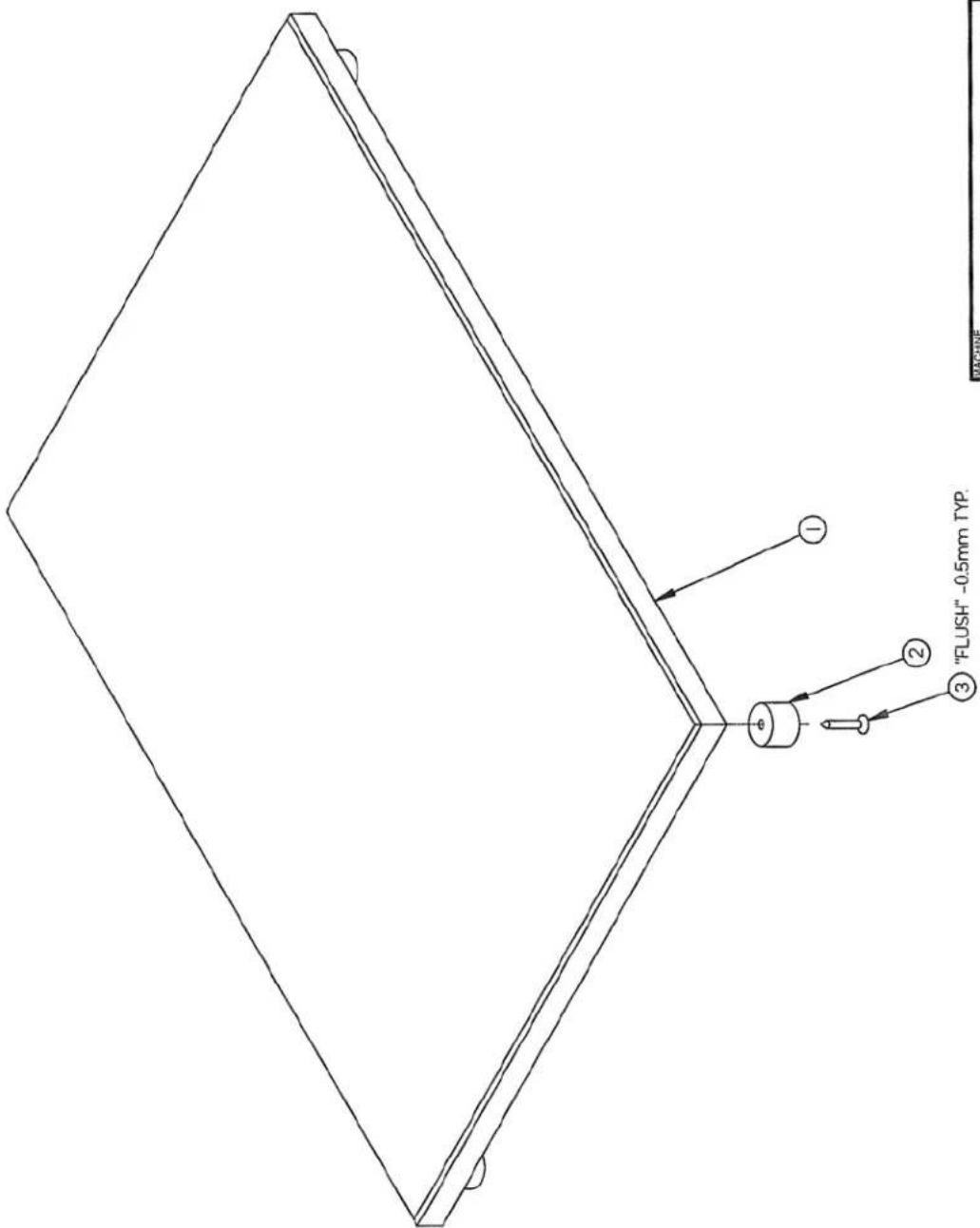
| ITEM | PART # | DESCRIPTION | QT. |
| 1 | 004-0355 | BAG CUT SEAL BAR PRE-ASSEMBLY | 1 |
| 2 | 002-0512 | SEAL BAR SUPPORT | 1 |
| 3 | 051-0256 | BOLT 1/4"-20nc. X 1 3/4" CAP SKT S/S | 3 |
| 4 | 001-1960 | EXTERIOR BELLOWS COVER | 1 |
| 5 | 001-1856 | EXTERIOR BELLOWS COVER | 1 |
| 6 | 001A6229 | SEAL BAR GUIDE | 2 |
| 7 | 051-0740 | WASHER 1/4" FLAT S/S | 10 |
| 8 | 051-0250 | BOLT 1⁄4"-20nc. X 11⁄2" S/S | 4 |
| 9 | 051-0581 | NUT 1/4"-20 NYLON LOCK S/S | 6 |
| 10 | 051-0230 | HEX BOLT 1/4-20 x 1 1/4" SS | 2 |
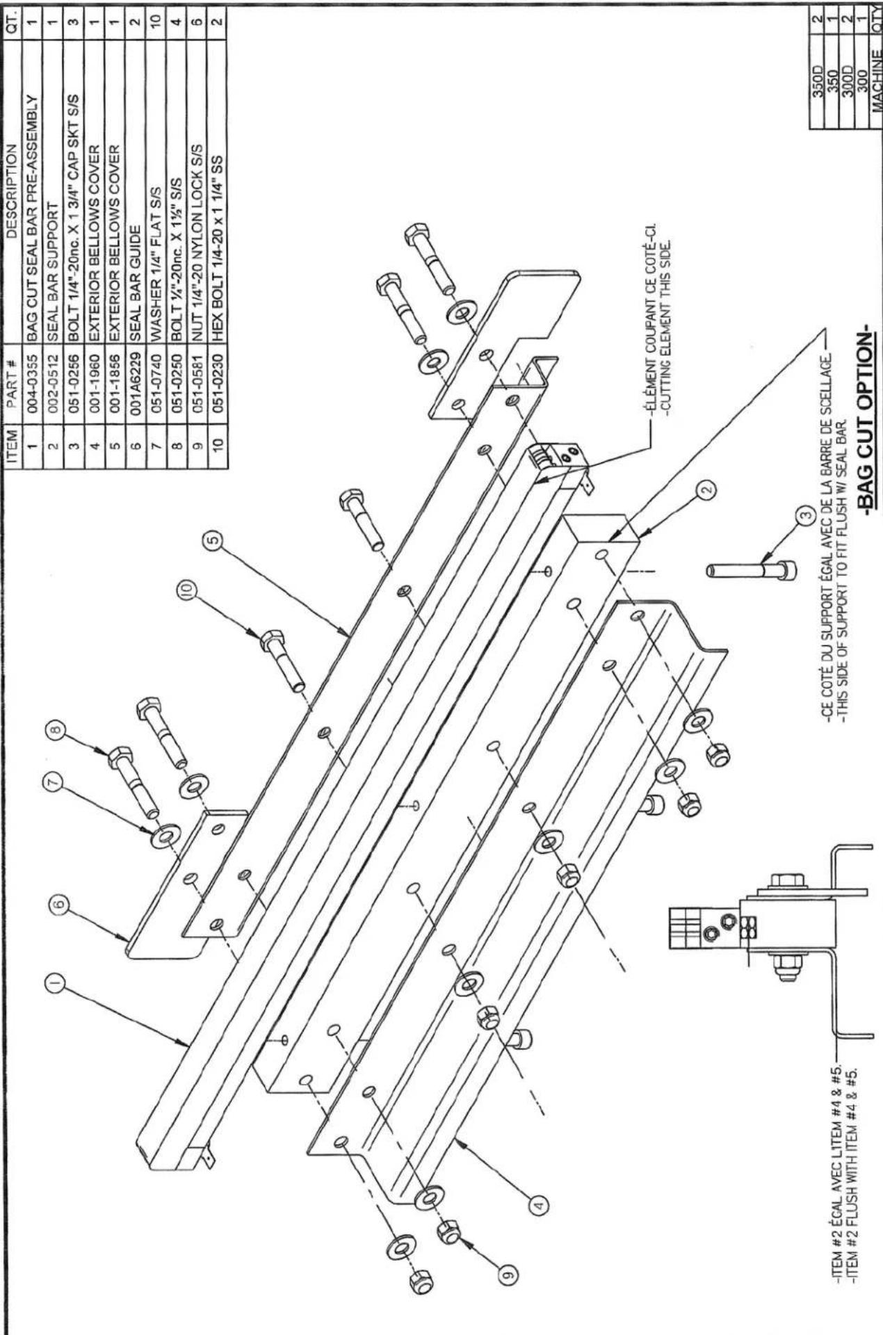
-END VIEW-
| 350D | 2 |
| 350 | 1 |
| 300D | 2 |
| 300 | 1 |
| MACHINE | QTY |
| MACHINE 300, 300D, 350 & 350D | DEPT. TOL. METRIC INCH | SIPROMAC ST-GERMAIN DE GRANTHAM QUEBEC CANADA | ||||
| USINAGE TOLERIE SOUDAGE | ±0.1 ±0.5 ±0.5 | ±0.004' ±0.020' ±0.020' | ||||
| PART SEAL BAR ASSEMBLY W/SUPPORT | N.T.S. | |||||
| ITEM | CNC | DEPT. M-I-(M) QTY. LIST | ||||
| MAT. | DWG BY J.G. | DATE 12-09-24 | NO. 005A1356 | |||
| APP BY | DATE | |||||
-BAG CUT OPTION-
-CE COTÉ DU SUPPORT ÉGAL AVEC DE LA BARRE DE SCELLAGE -THIS SIDE OF SUPPORT TO FIT FLUSH W/ SEAL BAR.
| A | REDESSINE ETAIT 005B0558 | 12-09-24 | J.G. |
| LET. | MODIFICATION | DATE | INT. |
| ITEM | #PART | DESCRIPTION | QT. |
| 1 | 002-0481 | SEAL BAR | 1 |
| 2 | 002-0031 | CONNECTOR | 2 |
| 3 | 039-0230 | REFLEX BAND 2.5MM (626mm EA.) | 0.063 |
| 4 | 039-0270 | "T" PROFILE CUT. ELEM. (626mm EA.) | 0.063 |
| 5 | 052-0395 | SCREW 1/4"-20 NC. X 5/16" SET HEX SKT OVAL PT | 4 |
| 6 | 052-0250 | SCREW #8-32 X 1 1/2" RND SLOT BRASS | 2 |
| 7 | 051-0550 | NUT #8-32 S/S | 4 |
| 8 | 176-0200 | TEFLON TAPE 5S ADHESIVE X 2" X (496mm EA.) | 0.063 |
| 9 | 027-0400 | CONNECTOR ADAPTOR 1/4" X #10 STUD | 2 |

| 450T | 2 |
| 450A | 2 |
| 400 | 2 |
| 350D | 2 |
| 350 | 1 |
| 300D | 2 |
| 300 | 1 |
| MACHINE | QTÉ. |
| MACHINE VOIR LISTE | TOLERANCE METRIC | INCH | SIPROMAC ST-GERMAIN DE GRANTHAM QUEBEC CANADA | |||
| USINAGE ± 0.1 TOLERER ± 0.5 SoudAGE ± 0.5 | ± 0.004" ± 0.020" | N.T.S. | ||||
| PART SEAL BAR PRE-ASSEMBLY | ||||||
| ITEM: | DNC: | M-I | QT. LISTE | |||
| MAT: | DWG A.P. APP. | DATE 98-02-10 | NO. 004-0355 | |||
-BAG CUT OPTION-
| F | ADDED 300, 300D, 350 & 350D WAS 005-0267 | 12-09-24 | J.G. |
| E | ADDED 450T WAS 005-0383 | 08-05-26 | D.A. |
| D | MODIFICATION #A-0398 (CONNECTEUR) | 04-04-19 | J.G. |
| C | ADDED 400 | 99-05-06 | S.L. |
| B | REDRAWN | 98-02-10 | A.P. |
| LET. | MODIFICATION | DATE | INT. |
005A0266
| ITEM | PART # | DESCRIPTION | QT. |
| 1 | 002A0025 | PLEXI COVER | 1 |
| 2 | 004A0021 | COVER HINGE ASSEMBLY | 1 |
| 3 | 051-0740 | WASHER 1/4" FLAT S/S | 6 |
| 4 | 051-0255 | BOLT 1/4-20 x 1-3/4" HEX SS | 4 |
| 5 | 051-0581 | NUT 1/4"-20 NYLON LOCK S/S | 4 |
| 6 | 051-0288 | BOLT 1/4-20 x 3 1/2" S/S | 2 |
| 7 | 076-0010 | "O" RING 1/4" x 3/8" x 1/16" | 2 |
| 8 | 002-0026 | UPPER SEAL BAR SPACER | 2 |
| 9 | 004B0173 | UPPER SEAL BAR PRE-ASS'Y | 1 |
| 10 | 179-0005 | NEOPRENE SPONGE 3/8" O.D. 2042mm (6.7") | 1 |
| 11 | 001A2919 | WASHER 0.381"ID X 1.062"OD X 3 | 4 |

| MACHINE 300 & 350 | DEPT. TOL METRIC INCH | SIPROMACST-GERMAIN DE GRANTHAMQUEBEG CANADA | ||||
| USINAGE ±0.1 ±0.020TOLERIE ±0.5 ±0.020SOUDAGE ±0.5 ±0.020 | ||||||
| PART COVER ASSEMBLY | ||||||
| N.T.S. | ||||||
| ITEM | CNC | DEPT.M-(M) QTY.1 | ||||
| MAT. | DWG BY J.G. | DATE 12-10-15NO005A0266 | ||||
| APP. BY | DATE | |||||
005A0481
| ITEM | PART # | DESCRIPTION | QT. |
| 1 | 002A0392 | PLEXI COVER | 1 |
| 2 | 004A0021 | COVER HINGE ASSEMBLY | 1 |
| 3 | 051-0740 | WASHER 1/4" FLAT S/S | 8 |
| 4 | 051-0255 | BOLT 1/4-20 x 1-3/4" HEX SS | 4 |
| 5 | 001A2919 | WASHER 0.381''ID X 1.062''OD X 3 | 4 |
| 6 | 051-0581 | NUT 1/4"-20 NYLON LOCK S/S | 4 |
| 7 | 051-0288 | BOLT 1/4-20 x 3 1/2" S/S | 4 |
| 8 | 076-0010 | "O" RING 1/4" x 3/8" x 1/16" | 4 |
| 9 | 002-0026 | UPPER SEAL BAR SPACER | 4 |
| 10 | 004B0173 | UPPER SEAL BAR PRE-ASS'Y | 2 |
| 11 | 179-0005 | NEOPRENE SPONGE 3/8" O.D. 2042mm (6.7') | 1 |

| MACHINE 300D & 350D | DEPT. TOL | METRIC | INCH | SIPROMAC ST-GERMAIN DE GRANTHAM QUEBEC CANADA | ||
| USINAGE | ±01 | ±0.004" | ||||
| TOLERIE | ±05 | ±0.020" | ||||
| SOUDAGE | ±05 | ±0.020" | ||||
| PART COVER ASSEMBLY | N.T.S. | |||||
| ITEM | CNC | DEPT. M-(M) | QTY. 1 | |||
| MAT. | DWG BY J.G. | DATE 12-10-15 | NO. 005A0481 | |||
| APP BY | DATE | |||||
| ITEM | PART # | DESCRIPTION | QT. |
| 1 | 002B0377 | UPPER SEAL BAR SUPPORT | 1 |
| 2 | 008A0291 | UPPER SEAL BAR RUBBER | 1 |

| 350D | 2 |
| 350 | 1 |
| 300D | 2 |
| 300 | 1 |
| MACHINE | QTY |
| MACHINE 300, 300D, 350 & 350D | DEPT. TOL | METRIC | INCH | SIPROMAC ST-GERMAIN DE GRANTHAM QUEBEC CANADA | ||
| USIAGETOLERIE Soudage | ±0.1 ±0.5 ±0.5 | ±0.00" ±0.020" | ||||
| PART UPPER SEAL BAR PRE-ASS'Y | N.T.S. | |||||
| ITEM | CNC | DEPT. M-(M) | OYLISTE | |||
| MAT. | DWGBY J.G. | DATE 12-10-15 | NO 004B0173 | |||
| APP BY | DATE | |||||
| ITEM | PART # | DESCRIPTION | QT. |
| 1 | 008A0270 | FILLER PLATE | 1 |
| 2 | 003-0080 | FILLER PLATE FOOT | 4 |
| 3 | 054-0019 | METAL SCREW #10x1"FLAT PHIL S/S | 4 |
| MACHINE 300 & 350 | DEPT. TOL. IMETRIC INCH | ||||
| USINAGE ±0.1 TOLERIE ±0.5 SOUDAGE ±0.5 | ±0.004° ±0.020° ±0.020° | SIPROMAC ST-GERMAIN DE GRANTHAM QUEBEC CANADA | |||
| PART FILLER PLATE ASS'Y | N.T.S. | ||||
| ITEM | CNC | DEPT.M | QTY.1 | ||
| MAT. | DWG BY J.G. | DATE 12-10-15 | NO 005A0278 | ||
| APP. BY | DATE | ||||
C REDESSINE MODIF. A-462 12-10-15 J.G. LET. MODIFICATION DATE INT.
| ITEM | PART # | DESCRIPTION | QT. |
| 1 | 008A0337 | HALF FILLER PLATE | 1 |
| 2 | 003-0080 | FILLER PLATE FOOT | 4 |
| 3 | 054-0019 | METAL SCREW #10x1"FLAT PHIL S/S | 4 |
| MACHINE 300 & 350 | DEPT. TOL. METRIC INCH | SIPROMAC ST-GERMAIN DE GRANTHAM QUEBEG CANADA | ||||
| USINAGE ±0.1 ±0.027 TOLERIE ±0.9 ±0.227 SOLDAGE ±0.5 ±0.027 | ||||||
| PART HALF FILLER PLATE ASS'Y | N.T.S. | |||||
| ITEM | CNC | DEPT. M QTY. 2 | ||||
| MAT | DWG BY J.G. | DATE 12-10-15 NO.005A0364 | ||||
| APP.BY | DATE | |||||
C REDESSINE MODIF. A-462 12-10-15 J.G. LET. MODIFICATION DATE INT.
005A0365
| ITEM | PART # | DESCRIPTION | QT. |
| 1 | 008A0338 | FILLER PLATE | 1 |
| 2 | 003-0080 | FILLER PLATE FOOT | 4 |
| 3 | 054-0019 | METAL SCREW #10x1"FLAT PHIL S/S | 4 |
| MACHINE 300D & 350D | DEPT. TOL METRIC INCH | SIPROMAC ST-GERMAIN DE GRANTHAM QUEBEC CANADA | ||||
| USINAGE ±0.1 ±0.04TOLERIE ±0.207SOU DAGE ±0.5 ±0.207 | ||||||
| PART FILLER PLATE ASS'Y | N.T.S. | |||||
| ITEM | CNC | DEPT. M QTY. 2 | ||||
| MAT. | DWG BY J.G. | DATE 12-10-15 | NO. 005A0365 | |||
| APP. BY | DATE | |||||
C REDESSINE MODIF. A-462 12-10-15 J.G. LET. MODIFICATION DATE INT.
| ITEM | PART # | DESCRIPTION | QT. |
| 1 | 005B1347 | STAND PRE-ASS'Y (SHELF) | 1 |
| 2 | 051-0780 | WASHER 3/8" FLAT S/S | 4 |
| 3 | 051-0410 | BOLT 3/8"-nc. X 2.75" S/S | 4 |
| 4 | 130-0190 | PL. CASTER SWIVEL W/OUT BRAKE | 2 |
| 5 | 051-0620 | NUT 3/8"-16 NC S/S | 4 |
| 6 | 130-0195 | PL. CASTER SWIVEL W/BRAKE | 2 |
| 7 | 075-0040 | BUSHING 3/8" x 1/2" x 5/8" PLAIN | 4 |

| MACHINE 300, 300D, 350 & 350D | DEPT. TOI | METRIC | INCH. | SIPROMAC ST-GERMAIN DE GRANTHAM QUEBEC CANADA | ||
| USNAGE | ±0.1 | ±0.00" | ||||
| TOLERIE | ±0.5 | ±0.020" | ||||
| Soudage | ±0.5 | ±0.020" | ||||
| PART STAND ASSEMBLY | N.T.S. | |||||
| ITEM | CNC | DEPT. | M-(I) | QTY.1 | ||
| MAT. | DWG BY J.G. | DATE 12-10-15 | NO 005B1031 | |||
| APP BY | DATE | |||||

natural_image
Technical line drawings of three electrical components: a grid circuit, a mechanical device with wires, and a coiled inductor (no text or symbols)ELECTRICAL DRAWING
natural_image
Pure electrical circuit lines without any symbols
natural_image
Simple line drawing of a rectangular plate with a central oval and two circular holes (no text or symbols)
| category VACUUM PACK | model 350 | volt 120V/1PH/60HZ | SIPROMACSt-Germain de GranthamQUEBEC,CANADA | ||||
| systemMC-40 | circuit power | year 10 | month 07 | day 08 | block | ||
| usualfonctions | conceptXX | drawPP | appDL | 006-0220 PAGE 1 de 1 | |||
| options | |||||||

All unmarked wires are caliber #14 AWG. (006-0200 page 1)
| category VACUUM PACK | model 350 | volt 220V 1Ph 60Hz | SIPROMACSt-Germain de GranthanQUEBEC,CANADA | ||||
| system MC-40 | circuit power | year month day | block | ||||
| 05 | 04 | 25 | |||||
| usual fonctions | concept PP | draw PP | app DL | 006-0200 PAGE 1 de 1 | |||
| options | |||||||
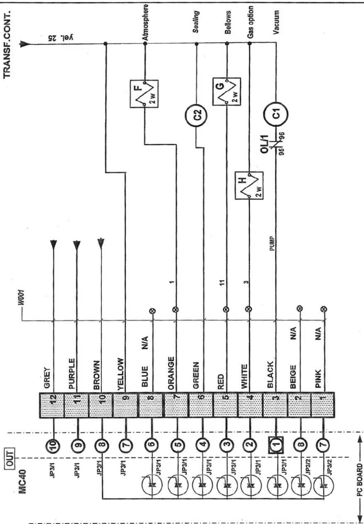
flowchart
graph TD
    A["MC40 OUT"] --> B["JP3/1 10"]
    A --> C["JP3/1 9"]
    A --> D["JP3/1 8"]
    A --> E["JP3/1 7"]
    A --> F["JP3/1 6"]
    A --> G["JP3/1 5"]
    A --> H["JP3/1 4"]
    A --> I["JP3/1 3"]
    A --> J["JP3/1 2"]
    A --> K["JP3/1 1"]
    A --> L["JP3/2 8"]
    A --> M["JP3/2 7"]

    B --> N["12 GREY"]
    C --> O["11 PURPLE"]
    D --> P["10 BROWN"]
    E --> Q["9 YELLOW"]
    F --> R["8 BLUE N/A"]
    G --> S["7 ORANGE"]
    H --> T["6 GREEN"]
    I --> U["5 RED"]
    J --> V["4 WHITE"]
    K --> W["3 BLACK"]
    L --> X["2 BEIGE N/A"]
    M --> Y["1 PINK N/A"]

    N --> Z["W001"]
    O --> AA["F 2 w Atmosphere"]
    P --> AB["ORANGE 1"]
    Q --> AC["C2"]
    R --> AD["RED 11"]
    S --> AE["H 2 w Gas option"]
    T --> AF["PUMP 95 OL/1 96 Vacuum"]

    U --> AG["G 2 w Bellows"]

    style A fill:#f9f,stroke:#333
    style B fill:#ccf,stroke:#333
    style C fill:#ccf,stroke:#333
    style D fill:#ccf,stroke:#333
    style E fill:#ccf,stroke:#333
    style F fill:#ccf,stroke:#333
    style G fill:#ccf,stroke:#333
    style H fill:#ccf,stroke:#333
    style I fill:#ccf,stroke:#333
    style J fill:#ccf,stroke:#333
    style K fill:#ccf,stroke:#333
    style L fill:#ccf,stroke:#333
    style M fill:#ccf,stroke:#333
    style N fill:#cfc,stroke:#333
    style O fill:#cfc,stroke:#333
    style P fill:#cfc,stroke:#333
    style Q fill:#cfc,stroke:#333
    style R fill:#cfc,stroke:#333
    style S fill:#cfc,stroke:#333
    style T fill:#cfc,stroke:#333
    style U fill:#cfc,stroke:#333
    style V fill:#cfc,stroke:#333
    style W fill:#cfc,stroke:#333
    style X fill:#cfc,stroke:#333
    style Y fill:#cfc,stroke:#333
    style Z fill:#cfc,stroke:#333

    subgraph PC BOARD
        direction LR
        direction LR
        OUT
        yel.25
        PC BOARD
        PC BOARD
        PC BOARD
        PC BOARD
        PC BOARD
        PC BOARD
        PC BOARD
        PC BOARD
        PC BOARD
        PC BOARD
        PC BOARD
        PC BOARD
        PC BOARD
        PC BOARD
        PC BOARD
        PC BOARD
        PC BOARD
        PC BOARD
        PC BOARD
        PC BOARD
        PC BOARD
        PC BOARD
        PC BOARD
        PC BOARD
        PC BOARD
        PC Board
        PC Board
        PC Board
        PC Board
        PC Board
        PC Board
        PC Board
        PC Board
        PC Board
        PC Board
        PC Board
        PC Board
        PC Board
        PC Board
        PC Board
        PC Board
        PC Board
        PC Board
        PC Board
        PC Board
        PC Board
        PC Board
        PC Board
        PC Board
        PC Board
        PCBoard
    end
| category VACUUM PACK | model 350 | volt. ALL | SIPROMACSt-Germain de GranthamQUEBEC,CANADA | ||||
| system MC-40 | circuit control | year month day | block | ||||
| 10 | 07 | 08 | |||||
| usual fonctions | concept | draw | app | 006-0237 PAGE 1 de 2 | |||
| options | XX | PP | DL | ||||

flowchart
graph TD
    A["IN"] --> B["MC40"]
    B --> C["JP4 1"]
    B --> D["JP4 2"]
    B --> E["JP4 3"]
    B --> F["JP4 4"]
    C --> G["1"]
    D --> H["2"]
    E --> I["3"]
    F --> J["4"]
    G --> K["BLACK"]
    H --> L["WHITE N/A"]
    I --> M["RED N/A"]
    J --> N["GREEN"]
    K --> O["WCV"]
    L --> P["CV"]
    M --> Q["shield"]
    N --> R["PC BOARD"]
| category | VACUUM PACK | model 350 | voll. ALL | SIPROMACSI-Germain de GranthanQUEBEC,CANADA | ||||
| system | MC-40 | dircuit control | year 10 | month 07 | day 08 | block | ||
| usual functions | concept XX | draw PP | app DL | 006-0237 PAGE 2 de 2 | ||||
| options | ||||||||
| #SIPRO | PARTDESCRIPTION | PARTAPPLICATION | MACHINEVOLTAGE | MACHINE | REF. | OPT. | QTY |
| 036-1500 | MALE PLUG 15 AMP./ 125 V. | SUPPLY | 120V/1PH/60HZ | 350 | GND-L1-N | 1 | |
| 030-0120 | CAB TIRE | SUPPLY | 120V/1PH/60HZ | 350 | GND-L1-N | 3 M. | |
| 028-0105 | GROUND BARRIER (5 HOLES) | SUPPLY | ALL | 350 | GND | 1 | |
| 034-0755 | FUSE HOLDER 30A 1 PÓLE | VACUUM KB-20 | 120V/1PH/60HZ | 350 | F1 | 1 | |
| 034-0530 | FUSE MIDGET 20A/250V TIME-DELAY | VACUUM KB-20 | 120V/1PH/60HZ | 350 | F1 | 1 | |
| 025-0030 | MOTOR CONTACTOR 1HP IN 120V-CSA,UL | VACUUM KB-20 | 120V/1PH/60HZ | 350 | C1 | 1 | |
| 025-0190 | THERMAL OVERLOAD 12 TO 18A CSA,UL | VACUUM KB-20 | 120V/1PH/60HZ | 350 | O/L | 1 | |
| 030-0430 | TEW #14/41 BLACK | VACUUM KB-20 | 120V/1PH/60HZ | 350 | WM1 | 1M. | |
| 030-0440 | TEW #14/41 GREEN | VACUUM KB-20 | 120V/1PH/60HZ | 350 | WM1 | 0.5M. | |
| 125-1020 | VACUUM PUMP 110-120V/1PH/60HZ 0.75KW/ 13A | VACUUM KB-20 | 120V/1PH/60HZ | 350 | M1 | 1 | |
| 034-0755 | FUSE HOLDER 30A 1 PÓLE | SEALING | 120V/1PH/60HZ | 350 | F2 | 1 | |
| 034-0450 | FUSE MIDGET 7A/250V TIME-DELAY | SEALING | 120V/1PH/60HZ | 350 | F2 | 1 | |
| 025-0020 | CONTACTOR ITH=25A-CSA,UL | SEALING | 120V/1PH/60HZ | 350 | C2 | 1 | |
| 029-0014 | TRANSFO 250VA, 120V/24V 60HZ | SEALING | 120V/1PH/60HZ | 350 | TR2 | 1 | |
| 027-0220 | TERMINAL ROUND STUD #10 600v 75°C | SEALING | ALL | 350 | WEL | 2 | |
| 030-0410 | TEW #10/104 BLACK | SEALING | ALL | 350 | WEL | 1.5M. | |
| 027-0065 | TERMINAL FLAG FEMALE YELLOW .250" | SEALING | ALL | 350 | WEL | 2 | |
| 005A0046 | SEAL BAR ASSEMBLY W/SUPPORT | SEALING TWIN SEAL | ALL | 350 | A1 | 1 | |
| 005A0558 | SEAL BAR ASSEMBLY W/SUPPORT | SEALING BAG CUT | ALL | 350 | A2 | 1 | |
| 034-0740 | FUSE HOLDER M4/8SF | CONTROL TRANSFO | 120V/1PH/60HZ | 350 | F5 | 1 | |
| 034-0200 | FUSE 5X20MM 3/4A 250V T-DELAY | CONTROL TRANSFO | 120V/1PH/60HZ | 350 | F5 | 1 | |
| 029-0008 | TRANSFO 65VA/120V/24-9V | CONTROL TRANSFO | 120V/1PH/60HZ | 350 | TR1 | 1 | |
| 034-0740 | FUSE HOLDER M4/8SF | CONTROL 9VAC+24VAC | ALL | 350 | F3+F4 | 2 | |
| 034-0210 | FUSE 5X20MM 2A/250V TIME DELAY | CONTROL 9VAC | ALL | 350 | F3 | 1 | |
| 034-0240 | FUSE 5X20MM 4A/250V TIME DELAY | CONTROL 24VAC | ALL | 350 | F4 | 1 | |
| 030-0590 | 20AWG/12COND.PVC,UNSHIELD.300V | OUTPUT CONTROL | ALL | 350 | W001 | 1M. | |
| 036-0740 | 12 CONTACTS CONNECTOR | OUTPUT CONTROL | ALL | 350 | JP3/1-2 | 1 | |
| 030-0631 | 22AWG/4COND.PVC,SHIELDED,300V. | INPUT CONTROL | ALL | 350 | WCV | 2M. | |
| 036-0820 | 0.156" CENTERLINE CRIMP HOUSING | INPUT CONTROL | ALL | 350 | JP4 | 1 | |
| 036-0850 | 0.156" CENTERLINE CRIMP TERMINAL | INPUT CONTROL | ALL | 350 | JP4 | 2 | |
| 033-0038 | MICROPROCESSOR MC-40 SENSOR VACUUM | CONTROL WITH SENSOR | ALL | 350 | MC-40 | B1 | 1 |
| 033-00385 | MICROPROCESSOR MC-40 NO SENSOR VAC. | CONTROL W/O SENSOR | ALL | 350 | MC-40 | B2 | 1 |
| 033-0015 | MEMBRANE MC-40 SIPROMAC | CONTROL SIPROMAC | ALL | 350 | C1 | 1 | |
| 033-0018 | MEMBRANE MC-40 BERKEL | CONTROL BERKEL | ALL | 350 | C2 | 1 | |
| 106-0020 | VALVE 2WAY 24V 1/2 NPT(G94) 60HZ | ATMOSPHERE | ALL | 350 | F | 1 | |
| 106-0070 | VALVE 3WAY 24V 1/4 NPT(G176) 60HZ | BELLows | ALL | 350 | G | 1 | |
| 106-0010 | VALVE 2WAY 24V 1/4 NPT(G22) 60HZ | OPTION GAS | ALL | 350 | H | D | 1 |
| 004-0261 | LIMIT SWITCH ASSY 15A 250V | COVER POSITION | ALL | 350 | CV | 1 | |
| 036-1512 | MALE PLUG 15 AMP./ 250 V. | SUPPLY | 220V/1PH/60HZ | 350 | GND-L1-L2 | 1 | |
| 030-0160 | CAB TIRE | SUPPLY | 220V/1PH/60HZ | 350 | GND-L1-L2 | 3 M. | |
| 028-0105 | GROUND BARRIER (6 HOLES) | SUPPLY | ALL | 350 | GND | 1 | |
| 034-0755 | FUSE HOLDER 30A 1 PÔLE | VACUUM KB-20 | 220V/1PH/60HZ | 350 | F1 | 2 | |
| 034-0500 | FUSE MIDGET 15A/250V TIME-DELAY | VACUUM KB-20 | 220V/1PH/60HZ | 350 | F1 | 2 | |
| 025-0010 | MOTOR CONTACTOR 1HP IN 220V MONO-CSA UL | VACUUM KB-20 | 220V/1PH/60HZ | 350 | C1 | 1 | |
| 025-0160 | THERMAL OVERLOAD 6.6 TO 8A-CSA UL | VACUUM KB-20 | 220V/1PH/60HZ | 350 | C/L1 | 1 | |
| 030-0430 | TEW #14/41 BLACK | VACUUM KB-20 | 220V/1PH/60HZ | 350 | WM1 | 1M | |
| 030-0440 | TEW #14/41 GREEN | VACUUM KB-20 | 220V/1PH/60HZ | 350 | WM1 | 0.5M | |
| 125-1021 | BUSCH KB-0020 220-240V/1PH/60HZ 0.75KW 8.5A | VACUUM KB-20 | 220V/1PH/60HZ | 350 | M1 | 1 | |
| 034-0755 | FUSE HOLDER 30A 1 PÔLE | SEALING | 220V/1PH/60HZ | 350 | F2 | 2 | |
| 034-0445 | FUSE MIDGET 5A/250V TIME-DELAY | SEALING | 220V/1PH/60HZ | 350 | F2 | 2 | |
| 025-0020 | CONTACTOR ITH=25A-CSA,UL | SEALING | 220V/1PH/60HZ | 350 | C2 | 1 | |
| 029-0018 | TRANSFO 250VA 220V/24V 50/60HZ | SEALING | 220V/1PH/60HZ | 350 | TR2 | 1 | |
| 027-0220 | TERMINAL ROUND STUD #10 600V 75°C | SEALING | ALL | 350 | WEL | 2 | |
| 030-0410 | TEW #10/104 BLACK | SEALING | ALL | 350 | WEL | 1.5M. | |
| 027-0065 | TERMINAL FLAG FEMALE YELLOW .250" | SEALING | ALL | 350 | WEL | 2 | |
| 005A0046 | SEAL BAR ASSEMBLY W/SUPPORT | SEALING TWIN SEAL | ALL | 350 | A1 | 1 | |
| 005A0558 | SEAL BAR ASSEMBLY W/SUPPORT | SEALING BAG CUT | ALL | 350 | A2 | 1 | |
| 034-0740 | FUSE HOLDER M4/8SF | CONTROL TRANSFO | 220V/1PH/60HZ | 350 | F5 | 2 | |
| 034-0200 | FUSE 5X20MM 3/4A 250V/T-DELAY | CONTROL TRANSFO | 220V/1PH/60HZ | 350 | F5 | 2 | |
| 029-0007 | TRANSFO 65VA/220-230-460V/24-9 | CONTROL TRANSFO | 220V/1PH/60HZ | 350 | TR1 | 1 | |
| 034-0740 | FUSE HOLDER M4/8SF | CONTROL 9VAC+24VAC | ALL | 350 | F3+F4 | 2 | |
| 034-0210 | FUSE 5X20MM 2A/250V TIME-DELAY | CONTROL 9VAC | ALL | 350 | F3 | 1 | |
| 034-0240 | FUSE 5X20MM 4A/250V TIME-DELAY | CONTROL 24VAC | ALL | 350 | F4 | 1 | |
| 030-0590 | 20AWG/12COND.PVC,UNSHIELD.300V | OUTPUT CONTROL | ALL | 350 | W001 | 1M. | |
| 036-0740 | 12 CONTACTS CONNECTOR | OUTPUT CONTROL | ALL | 350 | JP3/1-2 | 1 | |
| 030-0631 | 22AWG/4COND.PVC,SHIELDED,300V. | INPUT CONTROL | ALL | 350 | WCV | 2M. | |
| 036-0820 | 0.156" CENTERLINE CRIMP HOUSING | INPUT CONTROL | ALL | 350 | JP4 | 1 | |
| 036-0850 | 0.156" CENTERLINE CRIMP TERMINAL | INPUT CONTROL | ALL | 350 | JP4 | 2 | |
| 033-0038 | MICROPROCESSOR MC-40 SENSOR VACUUM | CONTROL WITH SENSOR | ALL | 350 | MC-40 | B1 | 1 |
| 033-00385 | MICROPROCESSOR MC-40 NO SENSOR VAC. | CONTROL W/O SENSOR | ALL | 350 | MC-40 | B2 | 1 |
| 033-0015 | MEMBRANE MC-40 SIPROMAC | CONTROL SIPROMAC | ALL | 350 | C1 | 1 | |
| 033-0018 | MEMBRANE MC-40 BERKEL | CONTROL BERKEL | ALL | 350 | C2 | 1 | |
| 106-0020 | VALVE 2WAY 24V 1/2 NPT(G94) 60HZ | ATMOSPHERE | ALL | 350 | F | 1 | |
| 106-0070 | VALVE 3WAY 24V 1/4 NPT(G176)60HZ | BELLOWS | ALL | 350 | G | 1 | |
| 106-0010 | VALVE 2WAY 24V 1/4 NPT(G22) 60HZ | OPTION GAS | ALL | 350 | H | D | 1 |
| 004-0261 | LIMIT SWITCH ASSY 16A 250V | COVER POSITION | ALL | 350 | CV | 1 | |
natural_image
Simple line drawing of a circular gauge or dial with a central pointer (no text or symbols)PNEUMATIC DRAWING

| 007-0022
| ITEM | PART # | DESCRIPTION | QT. |
| 1 | 106-0010 | GAS VALVE | 1* |
| 2 | 114-0260 | VACUUM GAUGE | 1 |
| 3 | 106-0070 | BELLOWS VALVE | 1 |
| 4 | 106-0020 | ATMOSPHERE VALVE | 1 |
| 5 | 114-0147 | PRESSURE REGULATOR | 1* |
| 6 | 114-0245 | PRESSURE GAUGE | 1* |
| 7 | 114-0170 | PRESSURE REGULATOR SUPPORT | 1* |
| *: OPTION | |||

flowchart
graph TD
    A["INERT GAS"] --> B["IN"]
    B --> C["OUT"]
    C --> D["GAS OPTION"]
    D --> E["②"]
    E --> F["BELLows"]
    F --> G["③"]
    G --> H["GAS INJECTOR"]
    H --> I["①"]
    I --> J["④"]
    J --> K["PUMP"]
    L["AIR REGULATOR OPTION"] --> M["NOTE: SET TO A MAXIMUM OF 45 PSI"]
    M --> N["⑤ ⑥ ⑦"]
    N --> O["AIR INLET"]
    P["NOTE: FOR GAS INJECTION KIT INSTALLATION SEE DRAWING #: 350: #010-0015 350D: #010-0026"] --> Q["-NOTE"]
| MACHINE 350 & 350D | SIPROMAC | |||||
| PART PNEUMATIC | N.T.S. | ST-GERMAIN DE GRANTHAM QUEBEC CANADA | ||||
| ITEM: ____ | CNQ: ____ | SCALE ____ | QT. 1 | |||
| MAT: ____ | DWG BY M.LAVIGNE APP. | DATE 97-03-11 | NO. 007-0022 | |||
| DATE | ||||||
| A | RE-DRAWN | 97-03-11 | M.L. |
| LET. | MODIFICATION | DATE | INT. |
| ITEM | PART # | DESCRIPTION | QT. |
| 1 | 005-0426 | MACHINE ASSEMBLY REAR VIEW | 1 |
| 2 | 004-0361 | REAR PANNEL PRE-ASSEMBLY | 1 |
| 3 | 005-0323 | GAS INLET ASSEMBLY | 1 |
| 4 | 051-0180 | BOLT 1/4"-20 NC X 1/2" S/S | 1 |
| 5 | 051-0740 | FLAT WASHER 1/4" S/S | 1 |
| 6 | 051-0581 | NYLON NUT 1/4"-20 NC S/S | 1 |
| 7 | 114-0245 | PRESSURE GAUGE 0-60 PSI. 1/8" NPT. | 1 |
| 8 | 101-0608 | ELBOW 90° 1/8" NPT. BR. | 1 |
| 9 | 101-0302 | HEX. NIPPLE 1/8" NPT. BR. | 1 |
| 10 | 114-0147 | PRESSURE REGULATOR 0-60 PSI. 1/4" NPT. | 1 |
| 11 | 114-0170 | PRESSURE REGULATOR SUPPORT W/ LOCKING COLLAR | 1 |
| 12 | 051-0108 | SCREW #8-32 NC. X 1/2" (PAN PHIL.) S/S | 2 |
| 13 | 051-0560 | NUT #8-32 NC. S/S NYLON | 2 |
| 14 | 101-0058 | ELBOW 90° 1/4" MNPT X 3/8" T.P. COMP. | 1 |
| 15 | 101-0036 | STRAIGHT 1/4" MNPT X 3/8" T.P. COMP. | 1 |
| 16 | 105-0200 | 1 EAR CLAMP 3/8"∅ ZINC | 1 |
| 17 | 104-0060 | TUBE 3/6" O.D. X 1/4" LD. X MM. LG. POLYETYLENE | 4 |
| 18 | 104-0060 | TUBE 3/6" O.D. X 1/4" LD. X MM. LG. POLYETYLENE | 1 |

DRILL 7/32" 2 HOLES
-AIR PRESSURE REGULATOR OPTION-
| MACHINE 350 & 350D | METRO TOLERANCE ± .2 .3 ± .05" .00 ± .000" .000 ± .000" N.T.S. | SIPROMAC ST-GERMAIN DE GRANTHAM QUEBEC CANADA | |||
| PART AIR REGULATOR OPTION KIT INSTALLATION | |||||
| ITEM: | CNQ: | M-I | QT. 1 | ||
| MATR | BY A. PROVENCHER APP. | DATE:97-01-28 DATE:07-02-19 | NO. 010-0030 | ||
| B | DRILLED HOLES LEFT SIDE WAS RIGHT SIDE 152 WAS 61 / 50 WAS 64 | 07-02-15 | D.A. |
| A | MODIFICATION NO: A--0196 | 97-04-08 | A.P. |
| LET. | MODIFICATION | DATE | INT. |
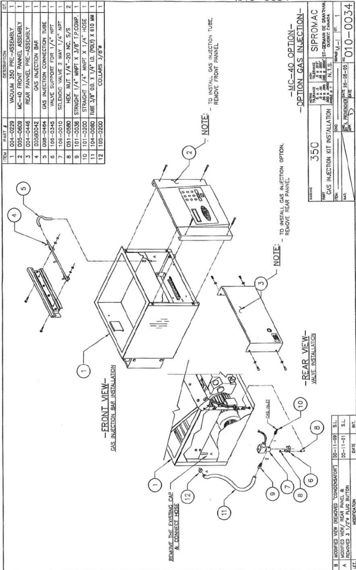
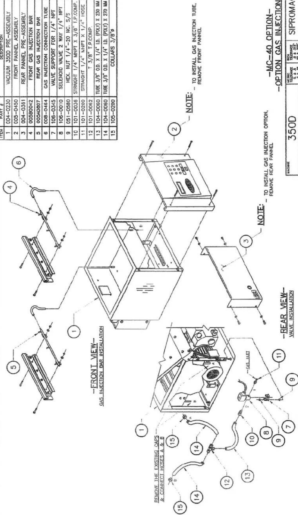
| ITEM | PART # | DESCRIPTION | QT. |
| 1 | 004-0230 | VACUUM 350D PRE-ASSEMBLY | 1 |
| 2 | 005-0450 | FRONT PANNEL ASSEMBLY | 1 |
| 3 | 004-0361 | REAR PANNEL PRE-ASSEMBLY | 1 |
| 4 | 005B0042 | FRONT GAS INJECTION BAR | 1 |
| 5 | 005A0807 | REAR GAS INJECTION BAR | 1 |
| 6 | 008-0464 | GAS INJECTION CONNECTION TUBE | 2 |
| 7 | 106-0345 | VALVE SUPPORT FOR 1/4" NPT | 1 |
| 8 | 106-0010 | SELENOID VALVE 2 WAY 1/4" NPT | 1 |
| 9 | 051-0580 | HEX. NUT 1/4"-20 NC. S/S | 2 |
| 10 | 101-0036 | STRAIGHT 1/4" MNPT X 3/8" T.P.COMP. | 1 |
| 11 | 101-0200 | STRAIGHT 1/4" MNPT X 1/4" HOSE | 1 |
| 12 | 101-0062 | T 3/8" T.P.COMP. | 1 |
| 13 | 104-0060 | TUBE 3/8" O.D. X 1/4" I.D. (POLY) X 230 MM | 1 |
| 14 | 104-0060 | TUBE 3/8" O.D. X 1/4" I.D. (POLY) X 270 MM | 2 |
| 15 | 105-0200 | COLLARS 3/8"∅ | 2 |
| C | MODIF. fA-358 | 03-02-21 | J.G. |
| B | MODIFIED VIEW (REMOVED "CONDENSATOR") | 00-11-09 | S.L. |
| A | MODIFIED VIEW/ REAR PANEL & REMOVED 3 1/2"ø PLUG BUTTON | 00-11-01 | S.L |
| LET. | MODIFICATION | DATE | INT. |
| MACHINE 350D | MERIC TOLERANCE 0.±.5 .0±.05 .00±.015 .000±.000 ANGLE ±.° | INCH TOLERANCE .0±.015" .00±.005" .000±.000" | SIPROMAC ST-GERMAIN DE GRANTHAU QUEBEC CANADA | |
| PART GAS INJECTION KIT INSTALLATION | ||||
| ITEM: | CNQ | GENIE-M-HP CT. 1 | ||
| DATE: | DWG BY A. PROVENCHER APP. LT. | NO. 010-0035 | ||
TO INSTALL GAS INJECTION OPTION, REMOVE REAR PANNEL
-REAR VIEW- VALVE INSTALLATION
-MC-40 OPTION- -OPTION GAS INJECTION-

| ITEM | PART # | DESCRIPTION | OT. |
| 1 | 005-0611 | MC-40 FRONT VIEW ASSEMBLY | 1 |
| 2 | 106-0070 | SOLENCIDE VALVE 3 WAYS 24V 60Hz 1/4 NPT | 1 |
| 3 | 101-0850 | T 1/4" FNPT X 1/4" MNPT X 1/4" FNPT BR. | 1 |
| 4 | 114-2020 | DRYER FILTER | 1 |
| 5 | 179-0008 | SILICONE TUBING 1/8" ID X 3/8" OD X 533 mm CREY 80 DURO | 1 |
| 6 | 052-0214 | SCREW #8-32 NC. X 3/8" PAN PHIL. TYPE F ZC | 2 |
| 7 | 101-0191 | ELBOW 90° 1/8" MNPT X 1/4" HOSE BR. | 1 |
| 8 | 101-0036 | STRAIGHT 1/4" MNPT X 3/8" T.P.COMP. | 2 |
| 9 | 101-0660 | ELBOW STREET 90° 1/4" NPT BR. | 1 |
| MACHINE 350 | METRIC TOLERANCE .0 ± .5 .00 ± .05 .00 ± .005 .000 ± .0005 ANGLE = 1° | INCH TOLERANCE .0 ± .015" .00 ± .005" .000 ± .0005" | SIPROMAC | ||
| PART DRYER FILTER INSTALLATION | ST-GERMAIN DE GRANTHAM, QUEBEC CANADA | ||||
| N.T.S. | |||||
| ITEM: | CNC: | SCALE M-1 | QT. 1 | ||
| MAT: | DWG BY A. PROVONCHER APP: | DATE: 98-08-19 | NO. 010-0037 | ||
| A | MODIFIED VIEW/ REAR PANELREMOVED 3 1/2"φ PLUG BUTTON | 00-11-01 | S.L. |
| LET. | MODIFICATION | DATE | INT. |

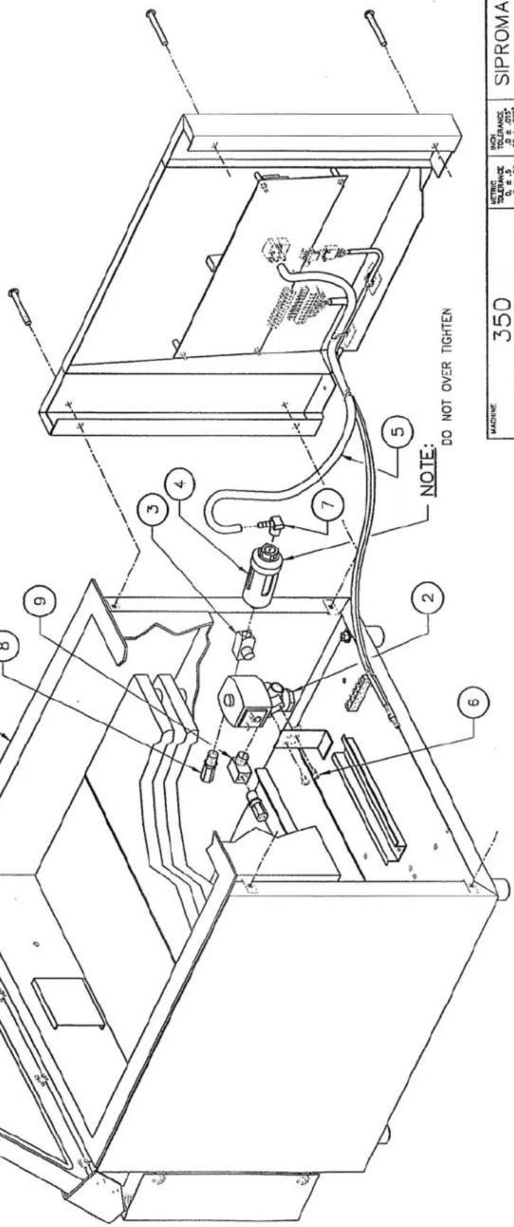
| ITEM | PART # | DESCRIPTION | GT. |
| 1 | 005-0611 | MC-40 FRONT VIEW ASSEMBLY | 1 |
| 2 | 106-0070 | SOLENOIDE VALVE 3 WAYS 24V 60Hz 1/4 NPT | 1 |
| 3 | 101-0850 | T 1/4" FNPT X 1/4" MNPT X 1/4" FNPT BR. | 2 |
| 4 | 114-2020 | DRYER FILTER | 1 |
| 5 | 179-0008 | SILUCONE TUBING 1/8" ID X 3/8" OD X 533 mm GREY 60 DURO | 1 |
| 6 | 052-0214 | SCREW #8-32 NC. X 3/8" PAN PHIL. TYPE F ZC | 2 |
| 7 | 101-0191 | ELBOW 90° 1/8" MNPT X 1/4" HOSE BR. | 2 |
| 8 | 101-0036 | STRAIGHT 1/4" MNPT X 3/8" T.P.COMP. | 2 |

| A | MODIFIED VIEW/ REAR PANEL & REMOVED 3 1/2" PLUG BUTTON | 00-11-01 | S.L. |
| LET. | MODIFICATION | DATE | NT. |
VACUUM PACKAGING MACHINES
250

350/350D
natural_image
Line drawing of a portable electronic device with open lid and wheels (no text or symbols)450A
natural_image
Line drawing of a portable electronic device with open lid and wheels (no text or symbols)550A


- OWNERS MANUAL
- IMPORTANT SAFETY INSTRUCTIONS SAVE THESE INSTRUCTIONS
- General Operation
- Service
- VACUUM PACKAGING MACHINE
- MODEL 350, 350D
- VACUUM PACKAGING MACHINES-OPERATION INSTRUCTIONS
- TABLE OF CONTENTS
- VACUUM PACKAGING MACHINES
- SETTING UP THE MACHINE:
- ELECTRICAL CONNECTION:
- OPERATION:
- Working principles:
- Special packaging:
- Gas flushing (option):
- Electrical bag cut (optional):
- Vacuum packaging operation:
- Basics:
- Functions menu:
- Create a program:
- Delete a program:
- Select operating mode:
- Programs menu:
- Program identification:
- Vacuum time setting (sensor disabled):
- Vacuum level setting (sensor enabled)
- Vacuum plus time setting (sensor enabled)
- Gas time setting (sensor disabled)
- Gas flush level setting: (sensor enabled)
- Sealing time setting:
- Vacuum cycle execution:
- System monitor:
- -MENUS STRUCTURE-
- - Functions menu:
- - Programs menu:
- • Diagnostics menu (keys "ESC" & "POWER" for access):
- -KEYBOARD DETAILS-
- MC-40 CONTROLS
- WARNING: All electrical work described in this brochure should be done by a QUALIFIED and AUTHORIZED technician.
- Daily cleaning
- TROUBLE SHOOTING:
- Failure during packaging cycle:
- "COVER DOWN ERROR" message is displayed on LCD(manual units):
- Insufficient vacuum:
- Leakage in the bag:
- No leakage in the bag:
- Insufficient vacuum in chamber:
- Faulty seal:
- Insufficient seal:
- No seal:
- Permanent sealing current:
- Seal does not stick:
- Fault in the valve:
- MC40 Control board failure
- Regular maintenance:
- 004A0361
- -BAG CUT OPTION-
- PNEUMATIC DRAWING
Brand : Berkel
Model : 350D
Category : Vacuum packaging