
M2000 - Kitchen machine Berkel - Free user manual and instructions
Find the device manual for free M2000 Berkel in PDF.

| Product Type | Continuous Feed Food Processor |
| Model | M2000 |
| Motor Power | 1/2 HP (115V, 7.5 Amps) |
| Voltage | 115V, 60Hz, 1-phase |
| Slicing Capacity | 600-650 lbs/hr |
| Dicing Capacity | 650-800 lbs/hr |
| Dimensions (W x H x D) | 20.375" x 18.25" x 8.5" (520 x 465 x 216 mm) |
| Weight | 41 lbs (18 kg) |
| Construction Material | Cast aluminum and stainless steel |
| Transmission | Poly V-Belt |
| Safety Features | Magnetic interlock, safety pushers |
| Certifications | UL Listed, NSF |
| Warranty | 1 year parts, labor, and travel (cutting edges and dicing grids excluded) |
| Cleaning | Hand wash only; do not use dishwasher |
| Maintenance | No lubrication required; sealed ball bearings |
| Accessories Included | Storage rack, small and large pushers |
| Feed Hopper | Two tubes (small and large), removable lid with magnetic lock |
| Country of Origin | USA |
| Attachment System | Interchangeable without tools |
| Application | Commercial kitchen, vegetables, cheese, etc. |
Frequently Asked Questions - M2000 Berkel
User questions about M2000 Berkel
0 question about this device. Answer the ones you know or ask your own.
Ask a new question about this device
Download the instructions for your Kitchen machine in PDF format for free! Find your manual M2000 - Berkel and take your electronic device back in hand. On this page are published all the documents necessary for the use of your device. M2000 by Berkel.
USER MANUAL M2000 Berkel
Continuous Feed Food Processors
natural_image
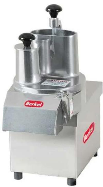
Exterior view of a stainless steel coffee maker with no visible text or symbols on the device itself.Model M2000 - 115V - 1/2 HP Model M3000 - 115V - 3/4 HP


Designed and Assembled in U.S.A.
COMPLETE RANGE OF SLICERS, DICING GRIDS AND SHREDDERS AVAILABLE.

BERKEL
2006 Northwestern Parkway
Louisville, KY 40203
800-348-0251
www.berkelequipment.com
Berkel
◆□■▼■◆□◆▲◆✿✿✿◆□□☆□□✿✿▲□□▲
(Cruise Ship and Navy Vessel Mounting)
TECHNICAL DATA AND PARTS LIST
PAGE 14 OVERALL SIDE VIEW
PAGE 15 FEED HOPPER LID
PAGE 16-17 INTERNAL VIEWS
PAGE 18 ELECTRICAL WIRING DIAGRAM
PAGE 19 ELECTRICAL WIRING DIAGRAM WITH TRIAC ASSEMBLY
PARTS LIST
PAGE 20-23 PARTS LIST
ACCESSORIES AND ACCESSORIES PARTS LIST
PAGE 26 SLICERS & SHREDDERS
PAGE27DICINGACCESSORIES
SPECIAL SLICERS FOR JULIENNE CUTS
PAGE 28 REPLACEMENT CUTTING EDGES & SHREDDER PLATES
PAGE 29 REPLACEMENT CUTTING EDGES & JULIENNE BARS
PAGE30EJECTORS
STORAGE RACK
PAGE 31-32 ACCESSORIES AND PARTS LIST FOR M2000/M3000
PAGE 33 REPAIR PARTS/REPAIR SERVICE
PAGE 34 WARRANTY
Berkel

natural_image
Row of black geometric shapes including squares, triangles, stars, and stars (no text or symbols)
• COMPACT AND STURDY DESIGN
ALL CAST ALUMINUM AND STAINLESS STEEL
• ATTACHMENTS ARE FULLY INTERCHANGEABLE WITHOUT TOOLS
• HIGH OUTPUT, SAVES TIME AND LABOR COST
• SIMPLE TO OPERATE AND EASY TO CLEAN
• SAFE - UL LISTED, NSF
• MADE IN U.S.A.
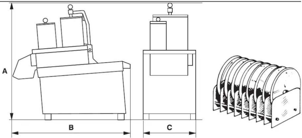
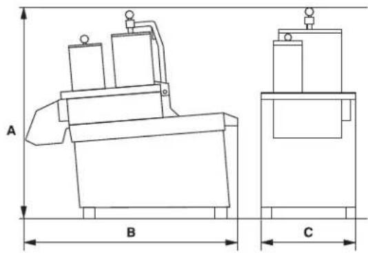
| MODEL | CAPACITYSLICINGlbs/hr | DICING | MOTOR | DIMENSIONS | WEIGHT | TRANSMISSION | ||
| M2000 | 600-650 | 1/2650-800 | HP115/60/17.5 AMPS | A 20.375"B 18.25"(465mm)C 8.5"(216mm) | (520mm)41 lbs.(18kg) | Poly V-Belt | ||
| M3000 | 800-900 | 3/41400-1500 | HP115/60/110.8 AMPS | A 23.25"(590mm)B 18.25"(465mm)C 8.5"(216mm) | 56 lbs.(25.5kg) | Poly V-Belt | ||
WARRANTY: One Year, Parts, Labor, and Travel. (Cutting edges and dicing grids not included.)
Berkel

natural_image
Row of black geometric symbols on white background, no text or labels present
| TYPE DESIGNATION SOME APPLICATIONS SIZE OF CUT | |||
 | SLICER S22 mm (1/16") | ColeslawRadishesOnionsCucumbers |  |
 | SLICER S33 mm (1/8") | Carrots, CeleryCucumbersZucchini, MushroomsLettuce for Tacos |  |
 | SLICER S55 mm (3/16") | Scalloped PotatoesCucumbers, CarrotsZucchini/SquashTomatoes |  |
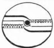 | SLICER S5CCRINKLE CUT5 mm (1/4") | CarrotsPotatoesCucumbers |  |
 | SHREDDER SH2Extra Fine2 mm (1/32") | Carrot Salad RawRoot Celery SaladParmesan Cheese |  |
 | SHREDDER SH33 mm (1/8") | Carrots JulienneCheese for Tacosand Salads |  |
 | SHREDDER SH44 mm (3/16") | CarrotsCheeseHash Browns |  |
 | SHREDDER SH77 mm (7/32") | CarrotsCheese for PizzaHash Browns |  |
 | SHREDDER SHPFine | Parmesan CheeseBread Crumbs |  |
Berkel
◆□■▼■◆□◆▲◆✿✿✿◆□□☆☆□✿✿▲▲□▲
| DICING GRID ALWAYSUSED WITH CORRESPONDING SLICER | DICING GRIDD 81/4" | DICING GRIDD 113/8" | DICING GRIDD 141/2" | DICING GRIDD 227/8" | MOST COMMONAPPLICATIONS | ||
| TYPE OFACCESSORY | DESIGNATION | 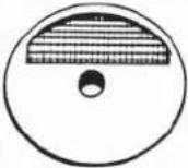 | 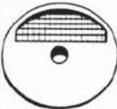 | 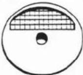 | 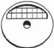 | MOSTOFTENUSEDVEGETABLES | USEDFOR |
 | SLICERS 53/16" |  3/16" x 1/4" 3/16" x 1/4" |  3/16" x 3/8"" 3/16" x 3/8"" |  3/16" x 1/2" 3/16" x 1/2" |  3/16" x 7/8" 3/16" x 7/8" | OnionsCeleryCarrotsPotatoes | MinestroneSoup |
 | SLICERS 81/4" |  1/4" x 1/4" 1/4" x 1/4" |  1/4" x 3/8" 1/4" x 3/8" |  1/4" x 1/2" 1/4" x 1/2" |  1/4" x 7/8" 1/4" x 7/8" | OnionsCeleryCarrotsPotatoesZucchini | SaladsSoupsSauteing |
 | SLICERS 113/8" |  3/8" x 1/4" 3/8" x 1/4" |  3/8" x 3/8" 3/8" x 3/8" |  3/8" x 1/2" 3/8" x 1/2" |  3/8" x 7/8" 3/8" x 7/8" | ApplesTomatoesOnionsCucumbersZucchiniPotatoesCarrots | Waldorf SaladMexican DishesSaladsChowderSteamedVegetables |
 | SLICERS 141/2" |  1/2" x 1/4" 1/2" x 1/4" |  1/2" x 3/8" 1/2" x 3/8" | 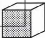 1/2" x 1/2" 1/2" x 1/2" |  1/2" x 7/8" 1/2" x 7/8" | TomatoesCucumbersPotatoesCarrotsCenteloupe | SaladsStewPotato SaladFruit Cups |
| Special Slicers for Julienne Cuts Dicing Grids are not NSF listed | |||||||
| TYPE | DESIGNATION | APPLICATION | SIZE OF CUT | ||||
 | SLICERJ 2x23/32" x 3/32" | STRAW POTATOESCARROTSCUCUMBERSRED BEETSZUCCHINI | 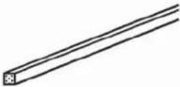 | ||||
 | SLICERJ 4x43/16" x 3/16" | CARROTS SHOE STRING POTATOESRED BEETSZUCCHINI YAMS (Sweet Potatoes) | 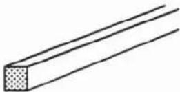 | ||||
 | SLICERJ 6x61/4" x 1/4" | FRENCH FRIES CUCUMBERSZUCCHINI YELLOW SQUASH | 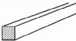 | ||||
OPERATING INSTRUCTIONS
- SAFETY NOTES
• INSTALLING OF SLICERS & SHREDDERS
• INSTALLING OF DICING GRIDS WITH CORRESPONDING SLICERS
•CLEANING
• PREVENTATIVE MAINTENANCE OF MACHINE AND ACCESSORIES
•WORKSTATIONRECOMMENDATIONS (Cruise Ship and Navy Vessel mounting)
OPERATING INSTRUCTIONS
SAFETY
WARNING: Injury to the operator and damage to the machine can result from incorrect use of this food processor. Read these instructions carefully and be sure that all users of the Berkel Food Processors are trained before being allowed to use the food processor.
CAUTION: Always use large and small SAFETY PUSHERS when operating the Berkel Continuous Feed Processor. Do not insert hands or fingers into the feed hopper openings while machine is operating.
The Berkel Continuous Feed Processor is equipped with a magnetic interlock between the feed hopper lid and the power base. The interlock prevents the machine from operating unless the feed hopper lid is in the proper position.
ALWAYS unplug the power cord before CLEANING the machine or at any time while the machine is not in use.
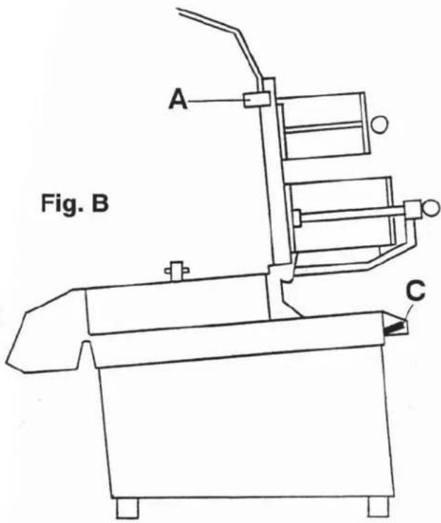
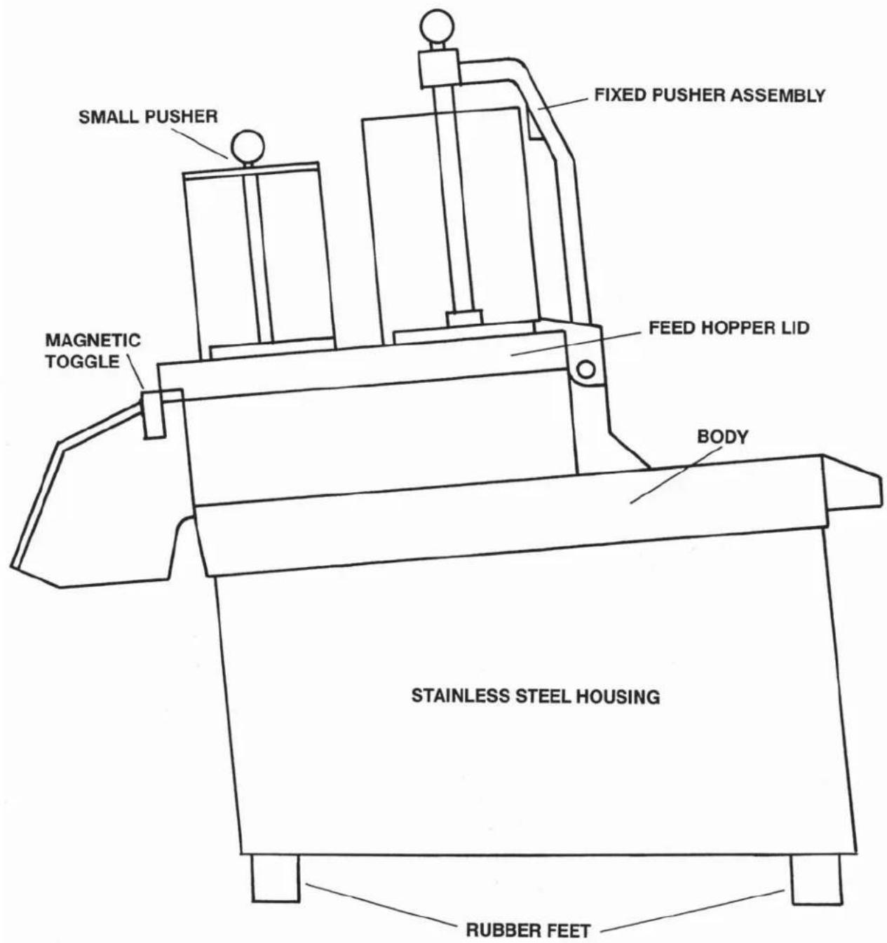
INSTALLING & REMOVING FEED HOPPER LID
WARNING: Always ensure that the ON/OFF switch (C) is in the OFF POSITION prior to installing or removing accessories.
REMOVING THE FEED HOPPER LID
Disengage the magnetic toggle lock (A) and open the feed hopper lid to the upright position (B). Slide feed hopper lid away from the food processor body.
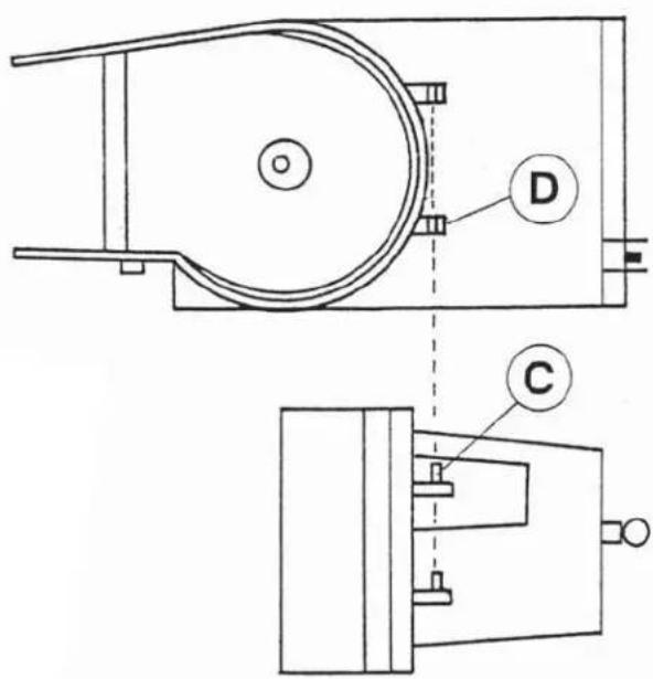
INSTALLING THE FEED HOPPER LID
To install the feed hopper lid, hold the feed hopper lid in the upright position and line up the long hinge pin (C) with the pin hole (D). Slide feed hopper lid towards the food processor base until both hinge pins are fully engaged. Close feed hopper lid.
INSTALLING & REMOVING SLICERS & SHREDDERS
OPERATING INSTRUCTIONS
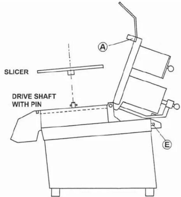
INSTALLING OF SLICERS, JULIENNE SLICERS AND SHREDDERS
Disengage the magnetic toggle lock (A) and open the feed hopper lid until it rests on the back of the base.
Select the desired SLICER and place it onto the drive shaft until the top of the slicer is flush with the top end of the drive shaft. Close the feed hopper lid and engage the magnetic toggle switch.
Turn the ON/OFF SWITCH into the ON POSITION and start slicing your vegetables, either using the small or large feed hopper tube.
REMOVING OF SLICING ACCESSORIES
Turn ON/OFF SWITCH to OFF POSITION (E). Disengage magnetic toggle lock (A) and open feed hopper lid until it rests on the back of the base.
Hold SLICER with both hands and rotate counter clockwise until the slicer bushing is disengaged from the drive shaft pin. Lift SLICER off the drive shaft, clean it and place the SLICER back into the storage rack which is automatically supplied with your new Berkel Food Processor.
Clean your Berkel Food Processor - SEE CLEANING - and close feed hopper lid. Unplug the power supply cord while the Berkel Food Processor is not in use.
INSTALLING & REMOVING DICING GRIDS & CORRESPONDING SLICERS
PRIOR TO USING YOUR NEW BERKEL FOOD PROCESSOR, READ THE OPERATING INSTRUCTIONS CAREFULLY.
WARNING: Always ensure that the ON/OFF switch is in the OFF position prior to installing or removing accessories.
INSTALLING OF DICING GRIDS WITH DICING SLICERS
Disengage the magnetic toggle lock (A) and open the feed hopper lid until it rests on the back of the base.
Select the desired DICING GRID and install it INTO THE TOP SEAT of the cutting compartment (B), top surface of DICING GRID facing up. (Size mark is located on top surface of grid - D8, D11, D14, D22). DICING GRID MUST BE FLUSH with the top rim of the cutting compartment.
Install the corresponding DICING SLICER (S8 with D8, S11 with D11, S14 with D14 or D22) by placing the SLICER onto the drive shaft above the DICING GRID. Top surface of slicer must be flush with top of drive shaft.
Close the feed hopper lid and engage the magnetic toggle lock. Turn the ON/OFF switch to the ON position.
IMPORTANT: Dice vegetables through the large feed hopper tube only!
REMOVING OF SLICING AND DICING ACCESSORIES
Turn ON/OFF SWITCH to OFF POSITION (E). Disengage magnetic toggle lock (A) and open feed hopper lid until it rests on the back of the base.
Hold SLICER with both hands and rotate counter clockwise until the slicer bushing is disengaged from the drive shaft pin. Lift SLICER off the drive shaft, clean it and place the SLICER back into the storage rack which is automatically supplied with your new Berkel Food Processor.
CLEAN THE DICING GRID WITH A CARROT WHILE THE GRID IS STILL LOCATED in the cutting compartment. We recommend the use of a carrot to push the remaining vegetables through the grid.
Place DICING GRID into the storage rack and CLEAN your Berkel Food Processor - SEE CLEANING - and close feed hopper lid. Unplug the power supply cord while storing the Berkel Food Processor in between uses.
INSTALLING & REMOVING DICING GRIDS & CORRESPONDING SLICERS

Berkel

CLEANING
WARNING: Unplug unit from power supply prior to cleaning. REMOVE FEED HOPPER LID and rinse thoroughly under running water. NEVER USE DISHWASHER. Feed hopper lid may be soaked in sanitizing lotion if desired.
HAND WIPING or RINSING of the cutting compartment of the Berkel Food Processor is recommended. Do not use pressure washer inside the cutting compartment.
WARNING: The SLICING AND DICING ACCESSORIES are equipped with SHARP KNIVES. Use caution when rinsing the accessories or when sanitizing. NEVER PLACE ACCESSORIES INTO THE DISH-WASHER and NEVER LEAVE ACCESSORIES submerged in sanitizing lotion unless attended by operator. IMMEDIATELY REMOVE accessories from sanitizing lotion after soaking and store in accessories storage rack in safe and visible place.
PREVENTATIVE MAINTENANCE
WARNING: The power cord must be disconnected prior to the start of any inspection or check-up.
ALWAYS REMOVE ANY ACCESSORIES from the Berkel Food Processor prior to any maintenance or inspection.
The Berkel Food Processor does not require periodic maintenance. All moving internal parts are quipped with DOUBLE SEALED BALL BEARINGS which are maintenance free. NO LUBRICATION REQUIRED.
DO NOT DIRECT water pressure or steam directly to the housing or bottom of the food processor.
TROUBLE SHOOTING GUIDE
MACHINE DOES NOT START
— Check power supply cord and outlet.
— Check whether feed hopper is properly installed and locked in place.
— Check whether magnet in toggle lock is intact. (Part #2110)
VEGETABLES WHEN DICING ARE NOT CONSISTENTLY DICED
— Ensure, when dicing, that you use large feed opening only. (See operating instructions)
— Place vegetables in hopper while machine is in OFF position. Place pusher on vegetables and exert sufficient pressure so that vegetables are in contact with slicer.
— When dicing celery and onions, while machine is running, feed one onion at a time and use pusher to hold onion or celery onto knife.
— Cutting edges on slicer or dicing grid are not sharp.
NOTE: It is important that constant pressure be applied on the vegetables.
FOOD PROCESSOR STALLS WHEN DICING OR SHREDDING CHEESE
— Check tension of Poly-V-Belt. (Consult parts manual and authorized service technician)
WORK STATION - MACHINE DIMENSIONS
(Cruise Ship and Navy Vessel Mounting)
TABLE TOP (Freestanding)
| MODEL | MOTOR | DIMENSIONS | WEIGHT |
| BERKEL 1/22000 115/60/ | HP A 20.31 B 18.25" | 75" (520mm) 41 lbs.(465mm) (17.5 kg)C 8.5" | (216mm) |
| BERKEL 3/4M3000 | HP A 23.2115/60/1 | 5" (533mm) 56 lbs.B 18.25" (465mm)C 8.5" | (25.5kg)(216mm) |
TABLE TOP (Permanent Installation) - Cruise Ship and Navy
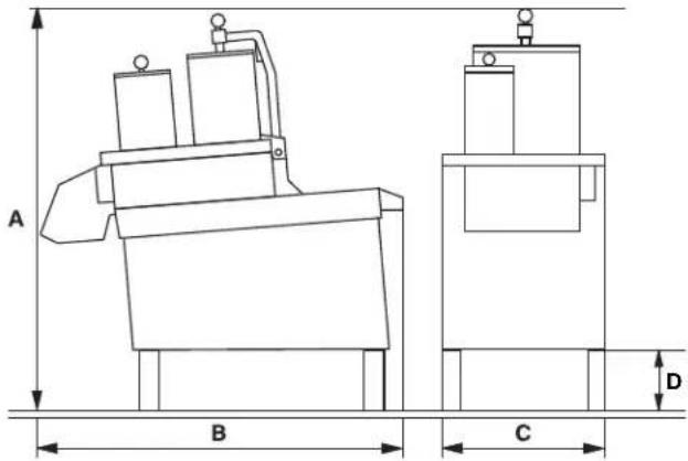
| MODEL | MOTOR | DIMENSIONS | WEIGHT |
| BERKEL 1/22000 115/60/Navy Legs Extension | HP A 24.3"1 B 18.25" | 75" (572mm) 41 lbs.(465mm) (17.5 kg)C 8.5"D 4.0" (102mm) | (216mm) |
| BERKEL 3/4M3000Navy Legs Extension | HP A 27.25"115/60/1 | 5" (635mm) 58 lbs.B 18.25" (465mm)C 8.5"D 4.0" (102mm) | (26kg)(216mm) |
MOUNTING DIMENSIONS FOR PERMANENT TABLE TOP INSTALLATION
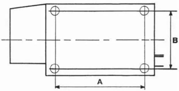
| MODEL | MOTOR | DIMENSIONS | WEIGHT |
| BERKEL 1/22000 115/60/ | HP A 10.31 B 7.2”7.5 | 75” (260mm) 41 lbs.(183mm) (18.5 kg)Amps | |
| BERKEL 3/4M3000 | HP A 10.3115/60/110.8 | 75” (260mm) 58 lbs.B 7.2” (183mm)Amps | (26kg) |
TECHNICAL DATA
AND
PARTS LIST
OVERALL SIDE VIEW
Berkel


Berkel

natural_image
Row of abstract geometric symbols including squares, triangles, stars, and dots (no text or labels)Berkel

natural_image
Row of abstract geometric symbols including squares, triangles, stars, and dots (no text or labels)MODEL M2000 and M3000
REED SWITCH ASSEMBLY WITH WIRES FOR M2000 (PART #2322-B)
REED SWITCH ASSEMBLY WITH WIRES FOR M3000 (PART #2322-C)
NOTE: The Reed Switch is a magnetically operated safety switch. It is not a fuse.
The contact closes when the Magnet in the toggle lock locates above the Reed Switch.
ELECTRICAL WIRING DIAGRAM

flowchart
graph TD
    A["TRIAC"] --> B["4 RELAY 3"]
    B --> C["A"]
    C --> D["REED SWITCH"]
    D --> E["White"]
    E --> F["ON/OFF SWITCH"]
    G["MOTOR PUSHER SAFETY REED SWITCH"] --> H["Ground"]
    I["CONTACT NORMALLY OPEN"] --> J["Black"]
    K["Black"] --> L["WHITE"]
    M["Ground"] --> N["Black"]
MODEL M2000 and M3000
REED SWITCH / TRIAC ASSEMBLY FOR MAGNETIC SAFETY PUSHER (PART #2322-A)
NOTE: The Reed Switch is a magnetically operated safety switch. It is not a fuse.
The contact closes when the Magnet in the toggle lock locates above the Reed Switch.
QUANTITY
PART# DESCRIPTION PER MACHINE
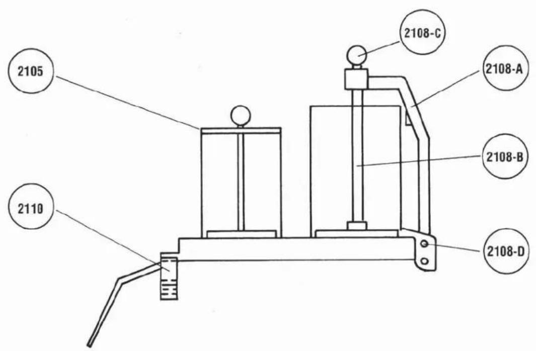
2100 FEED HOPPER LID (STANDARD) WITH MOUNTING 1 PINS BUT WITHOUT TOGGLE LOCK AND FIXED PUSHER ASSEMBLY
2100-A FEED HOPPER LID COMPLETE WITH MOUNTING 1 PINS, TOGGLE LOCK AND FIXED PUSHER ASSEMBLY
2105 PUSHER, SMALL 1
2106 PUSHER, LARGE (LOOSE) 1
2107 KNOB FOR PUSHERS #2105 & 2106 1
2108 FIXED PUSHER ASSEMBLY, COMPLETE 1 WITH MOUNTING PIN
2108-A FIXED PUSHER ARM WITH NYLON BUSHING 1
2108-B PUSHER PLATE WITH HEXAGON ROD 1
2108-C KNOB ASSEMBLY FOR FIXED PUSHER ONLY 1
2108-D MOUNTING PUSHER PIN 1
2108-H FIXED PUSHER ARM WITH NYLON BUSHING 1 AND MAGNET FOR SAFETY PUSHER
2108-MP FIXED PUSHER ASSEMBLY COMPLETE WITH 1 2 MAGNETS AND MOUNTING PIN
2110 TOGGLE LOCK WITH MAGNET 1
2110-A MAGNET ONLY FOR TOGGLE LOCK #2110 1
2110-B MAGNET ONLY FOR MAGNETIC SAFETY PUSHER 1
2111 SHOULDER BOLT FOR TOGGLE 1
3317-D ACORN NUT SS FOR UL ROD 1
2318 MIDTEX RELAY - 115V/60/1 FOR M2000 / M3000 1
2318-A MIDTEX RELAY - 115V/60/1 FOR M2000 1/2 HP 1
2318-E MIDTEX RELAY - 230/50/1 FOR EXPORT 1
2319 MOUNTING BAR FOR UL ROD AND RELAY 1
2320 RELAY MOUNTING SCREW WITH LOCKWASHER 2
2322-A REED SWITCH / TRIAC ASSEMBLY FOR MAGNETIC SAFETY PUSHER 1
2322-B REED SWITCH ASSEMBLY WITH WIRES FOR M2000 1
2322-C REED SWITCH ASSEMBLY WITH WIRES FOR M3000 1
2323 REED SWITCH MOUNTING BRACKET WITH 1 SCREW AND LOCKWASHER
2325 PULLEY LARGE 1
2325-E PULLEY LARGE, EXPORT 1
2326 POLY-V-BELT 240J6 1
2327 MOTOR PULLEY FOR M2000 1
2327-A HEXAGON BOLTS M5 WITH WASHERS FOR M2000 MOTOR PULLEY 1
Berkel
◆□■▼◆□◆▲◆✿✿✿◆□□☆□□✿▲▲□▲
2328 BELT TENSION BOLT WITH LOCKWASHER FOR M2000
3328 BELT TENSION BOLT WITH LOCKWASHER FOR M3000
2331 MOTOR MOUNTING FLANGE FOR M2000 1
2333 FASTENING BOLT WITH WASHERS FOR MOTOR FLANGE TO M2000 BODY 2
2334 SPLIT LOCKWASHER FOR MOTOR FLANGE BOLTS 1 M2000
2335 WASHER FOR MOTOR FLANGE BOLTS FOR M2000 1
3332 MOTOR MOUNTING FLANGE FOR M3000 1
3332-E MOTOR MOUNTING FLANGE FOR M3000 EXPORT 1
3333 FASTENING BOLT WITH WASHERS FOR MOTOR FLANGE TO M3000 BODY 4
3334 SPLIT LOCKWASHER FOR MOTOR FLANGE BOLTS 1 M3000 1
3335 WASHER FOR MOTOR FLANGE BOLTS FOR M3000 1
2349 HOUSING SS FOR M2000 1
3350 HOUSING SS FOR M3000 1
SPECIAL ACCESSORIES
2500 DIAMOND FILE TO SHARPEN CUTTING EDGES AND DICING GRIDS 1
Berkel

natural_image
Row of black geometric symbols on white background, no text or labels presentnatural_image
Row of black geometric symbols on white background, no text or labels presentnatural_image
Row of abstract geometric symbols including squares, triangles, stars, and dots (no text or labels)Special Slicers for Julienne Cuts
| TYPE | DESIGNATION | PART NUMBER | SIZE OF CUT |
 | SLICERJ 2x23/32" x 3/32" | Part # 2407 | 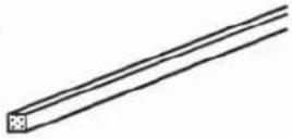 |
 | SLICERJ 4x43/16" x 3/16" | Part # 2408 |  |
 | SLICERJ 6x61/4" x 1/4" | Part # 2409 | 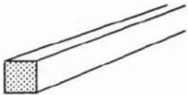 |
Berkel

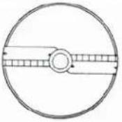
natural_image
Row of black geometric symbols on white background, no text or labels presentFor Slicers S2, S3, S5, S8, S11
Part # 2431
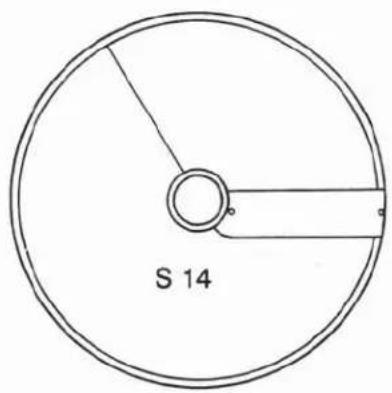
For Slicer S14 only
Part # 2432

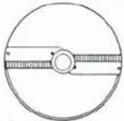
natural_image
Circular diagram with radial dots and a central hole, labeled '7' at the center (no text or symbols within the diagram itself)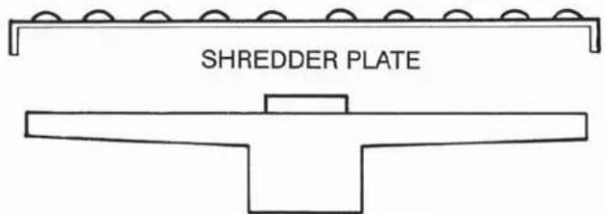
SHREDDER FRAME
SHREDDER FRAME
SHREDDER FRAME
SHREDDER PLATES
Part # 2422 for SH2, SH3
Part # 2423 for SH4, SH7, SHP
Part # 2475 for SH2
Part # 2476 for SH3
Part # 2477 for SH4
Part # 2478 for SH7
Part # 2479 for SHP
SCREWS
FOR SHREDDER PLATES
Part # 2435A
Berkel

natural_image
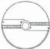
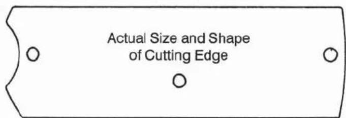
Row of black-and-white geometric symbols including squares, triangles, stars, and dots (no text or labels)REPLACEMENT CUTTING EDGES & JULIENNE BARS
Actual Size and Shape of Cutting Edge
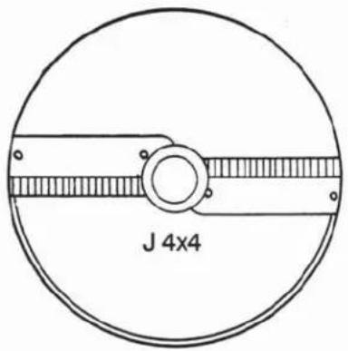
Cutting Edge for Julienne Slicers
Part # 2433
for J 2x2, J 4x4, J 6x6

Actual Size and Shape

natural_image
Simple line drawing of a ruler with three circular holes at the base (no text or markings)Cutting Bar
Part # 2436
for J 2x2
Actual Size and Shape

natural_image
Simple line drawing of a ruler with three circular end points (no text or symbols)Cutting Bar
Part # 2437
for J 4x4

Actual Size and Shape

natural_image
Simple line drawing of a ruler with three circular end points and vertical lines (no text or symbols)Cutting Bar
Part # 2438
for J 6x6
EJECTORS
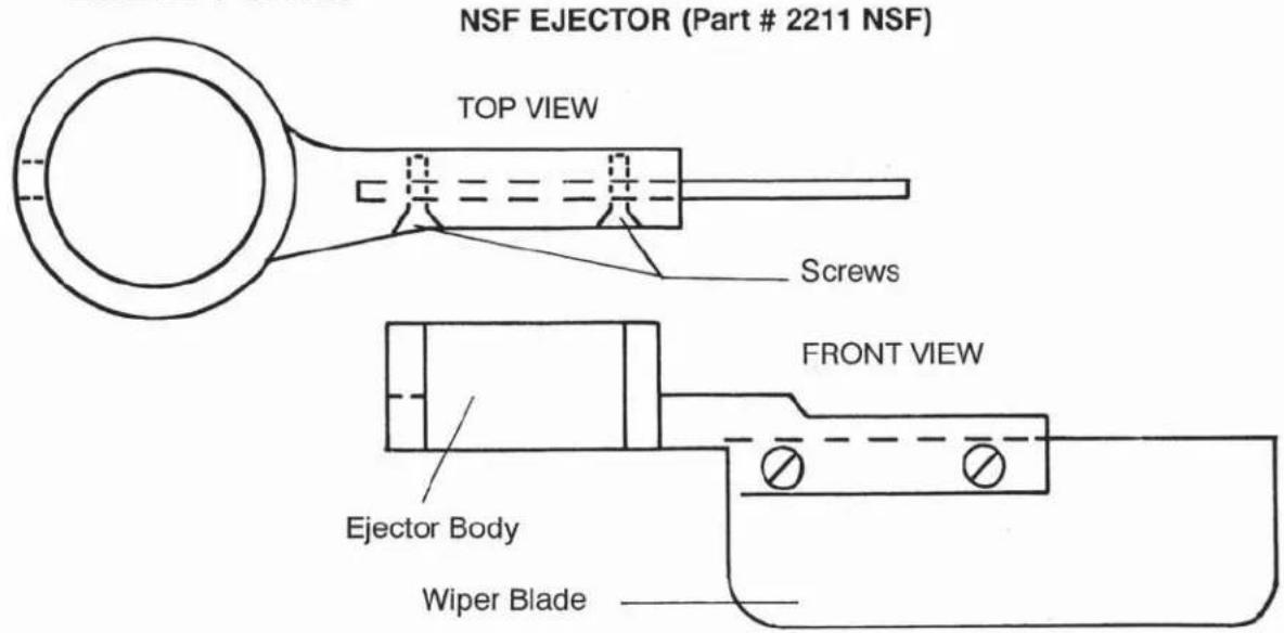
REPLACEMENT WIPER BLADE
REPLACEMENT SCREWS
Part # 2210
Part # 2210A
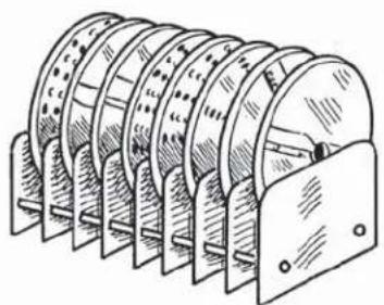
STORAGE RACK
natural_image
Technical line drawing of a multi-tiered mechanical component with mounting brackets (no text or symbols)2 SECTIONS (holds 2 Accessories)
3 SECTIONS (holds 3 Accessories)
4 SECTIONS (holds 4 Accessories)
5 SECTIONS (holds 5 Accessories)
6 SECTIONS (holds 6 Accessories)
7 SECTIONS (holds 7 Accessories)
8 SECTIONS (holds 8 Accessories)
9 SECTIONS (holds 9 Accessories)
10 SECTIONS (holds 10 Accessories)
Part # 2466
Part # 2467
Part # 2468
Part # 2469
Part # 2470
Part # 2471
Part # 2472
Part # 2473
Part # 2474
STORAGE RACK EXTENSION (per section)
Part # 2481
Berkel
BERKEL
PHONE: 800-348-0251
FAX: 800-444-0602
www.berkelequipment.com
ACCESSORIES AND PARTS LIST FOR M2000 / M3000
Slicers, Julienne Slicers, Shredders & Dicing Grids
Part # Description
| 2400 | SLICER | S1 |
| 2401 | SLICER | S2 |
| 2402 | SLICER | S3 |
2403 SLICER S5
2403-CC SLICER S5C (Crinkle Cut)
| 2404 | SLICER | S8 |
| 2405 | SLICER | S11 |
| 2406 | SLICER | S14 |
2407 JULIENNE SLICER J2X2
2408 JULIENNE SLICER J4X4
2409 JULIENNE SLICER J6X6
2410 SHREDDER SH2
2411 SHREDDER SH3
2412 SHREDDER SH4
2413 SHREDDER SH7
2415 SHREDDER SHP
2416 DICING GRID D8
2417 DICING GRID D11
2418 DICING GRID D14
2419 DICING GRID D22
2421 SPECIAL GRIDS
Berkel

natural_image
Row of black geometric symbols on white background, no text or labels presentShredder Frames and Plates only (unassembled)
Part # Description
2422 SHREDDER FRAME FOR SH2, SH3
2423 SHREDDER FRAME FOR SH4, SH7, SHP
2475 SHREDDER PLATE ONLY FOR SH2
2476 SHREDDER PLATE ONLY FOR SH3
2477 SHREDDER PLATE ONLY FOR SH4
2478 SHREDDER PLATE ONLY FOR SH7
2479 SHREDDER PLATE ONLY FOR SHP
Cutting Edges and Cutting Bars for Slicers and Julienne Slicers
Part # Description
2431 CUTTING EDGE FOR SLICERS S2, S3, S5, S8, S11
2432 CUTTING EDGE FOR SLICER S14
2433 CUTTING EDGE FOR JULIENNE SLICERS J2X2, J4X4, J6X6
2434 SCREWS FOR CUTTING EDGES
2435 SCREWS FOR CUTTING BARS
2435-A SCREWS FOR SHREDDER PLATES
2436 CUTTING BAR FOR JULIENNE SLICER J2X2
2437 CUTTING BAR FOR JULIENNE SLICER J4X4
2438 CUTTING BAR FOR JULIENNE SLICER J6X6
REPAIR PARTS/REPAIR SERVICE
Please contact a local Hobart Service branch or Authorized Berkel Service Contractor for any repair parts and/or repair service required on your Berkel food processor. Authorized locations can be found at www.berkelequipment.com or www.hobartservice.com. Then click on the SERVICE TAB and enter your ZIP CODE to find all of the Authorized Service Providers for your area. For warranty service only use a Hobart Service Branch or Authorized Berkel Warranty Contractor. Only use genuine Berkel parts.
Additional information may be obtained from:
ITW Berkel Company
2006 Northwestern Parkway
Louisville, KY 40203
800-348-0251

Get more done.
WARRANTY
Berkel Company (“Berkel”) warrants to the Buyer of new equipment that said equipment, when installed in accordance with our instructions and subjected to normal use, is free from defects in material or workmanship for a period of one (1) year from the date of sale ^1 .
BERKEL SPECIFICALLY DISCLAIMS ANY IMPLIED WARRANTY OF MERCHANTABILITY OR EXPRESS OR IMPLIED WARRANTY OF FITNESS FOR A PARTICULAR PURPOSE.
Berkel's obligation and liability under this warranty is expressly limited to repairing or replacing equipment that proves to be defective in material or workmanship within the applicable warranty period. Berkel or a Designated Berkel Service Location will perform all repairs pursuant to this warranty. Berkel expressly excludes responsibility for incidental or consequential damages to buyer or third party, including, without limitation, damages arising from personal injuries, lost profits, loss of business opportunity, loss of property, economic losses, or statutory or exemplary damages, whether in negligence, warranty, strict liability or otherwise.
This warranty does not apply to: periodic maintenance of equipment including but not limited to lubrication, replacement of worn blades, knives, stones, knobs, accessories, and miscellaneous expendable supply items, and other adjustments required due to installation set-up or normal wear.
These warranties are given only to the first purchaser from a Berkel Authorized Channel of Distribution. No warranty is given to subsequent transferees.
The foregoing warranty provisions are a complete and exclusive statement of the warranty between the buyer and the seller. Berkel neither assumes nor authorizes and persons to assume any other obligation or liability connection with said equipment.
This warranty supersedes any and all prior warranties to the subject hereof.

BERKEL
2006 NORTHWESTERN PARKWAY
LOUISVILLE, KY 40203
PHONE: 800-348-0251
FAX: 800-444-0602
www.berkelequipment.com


- Continuous Feed Food Processors
- Berkel
- ◆□■▼■◆□◆▲◆✿✿✿◆□□☆□□✿✿▲□□▲
- TECHNICAL DATA AND PARTS LIST
- PARTS LIST
- ACCESSORIES AND ACCESSORIES PARTS LIST
- ◆□■▼■◆□◆▲◆✿✿✿◆□□☆☆□✿✿▲▲□▲
- OPERATING INSTRUCTIONS
- SAFETY
- INSTALLING & REMOVING FEED HOPPER LID
- REMOVING THE FEED HOPPER LID
- INSTALLING THE FEED HOPPER LID
- INSTALLING & REMOVING SLICERS & SHREDDERS
- REMOVING OF SLICING ACCESSORIES
- INSTALLING & REMOVING DICING GRIDS & CORRESPONDING SLICERS
- INSTALLING OF DICING GRIDS WITH DICING SLICERS
- REMOVING OF SLICING AND DICING ACCESSORIES
- CLEANING
- PREVENTATIVE MAINTENANCE
- TROUBLE SHOOTING GUIDE
- MACHINE DOES NOT START
- VEGETABLES WHEN DICING ARE NOT CONSISTENTLY DICED
- FOOD PROCESSOR STALLS WHEN DICING OR SHREDDING CHEESE
- WORK STATION - MACHINE DIMENSIONS
- (Cruise Ship and Navy Vessel Mounting)
- MOUNTING DIMENSIONS FOR PERMANENT TABLE TOP INSTALLATION
- TECHNICAL DATA
- AND
- QUANTITY
- PART# DESCRIPTION PER MACHINE
- ◆□■▼◆□◆▲◆✿✿✿◆□□☆□□✿▲▲□▲
- SPECIAL ACCESSORIES
- REPLACEMENT CUTTING EDGES & JULIENNE BARS
- ACCESSORIES AND PARTS LIST FOR M2000 / M3000
- Part # Description
- REPAIR PARTS/REPAIR SERVICE
- WARRANTY
- BERKEL SPECIFICALLY DISCLAIMS ANY IMPLIED WARRANTY OF MERCHANTABILITY OR EXPRESS OR IMPLIED WARRANTY OF FITNESS FOR A PARTICULAR PURPOSE.
Brand : Berkel
Model : M2000
Category : Kitchen machine