RAZOR CUT 40 Air - Welding machine UNIMIG - Free user manual and instructions
Find the device manual for free RAZOR CUT 40 Air UNIMIG in PDF.

| Product Type | Plasma Cutter (Inverter) |
| Model | RAZOR CUT 40 Air |
| Brand | UNIMIG |
| Input Power | 230V AC, 50/60 Hz, Single Phase |
| Rated Output Current | 40 Amps |
| Cutting Thickness (Mild Steel) | Up to 12 mm (Maximum 20 mm at reduced quality) |
| Plasma Gas | Compressed Air (60-80 PSI) |
| Duty Cycle | 60% @ 40A / 100% @ 30A |
| Weight | Approx. 8.5 kg |
| Dimensions (L x W x H) | 400 x 180 x 280 mm |
| Pilot Arc | IFT (Inverter Frequency Technology) - Contact start with pilot arc capability |
| Key Features | Overload protection, thermal overload protection, air pressure regulation, LED indicators |
| Safety Features | Over-current protection, over-voltage protection, thermal shutdown, torch safety switch |
| Maintenance | Regular cleaning of torch and air filter; check cables and hoses for wear; replace consumables (electrode, nozzle, shield) |
| Spare Parts & Repairability | Consumables (electrode, nozzle, swirl ring, shield) and internal PCBs available through UNIMIG service centers |
| Included Accessories | Plasma torch, work clamp, air hose with regulator, spare consumable set |
Frequently Asked Questions - RAZOR CUT 40 Air UNIMIG
User questions about RAZOR CUT 40 Air UNIMIG
0 question about this device. Answer the ones you know or ask your own.
Ask a new question about this device
Download the instructions for your Welding machine in PDF format for free! Find your manual RAZOR CUT 40 Air - UNIMIG and take your electronic device back in hand. On this page are published all the documents necessary for the use of your device. RAZOR CUT 40 Air by UNIMIG.
USER MANUAL RAZOR CUT 40 Air UNIMIG
3YEAR PRODUCT WARRANTY
Unimig®
RAZOR CUT 40 AIR
U14001K | Operating Manual
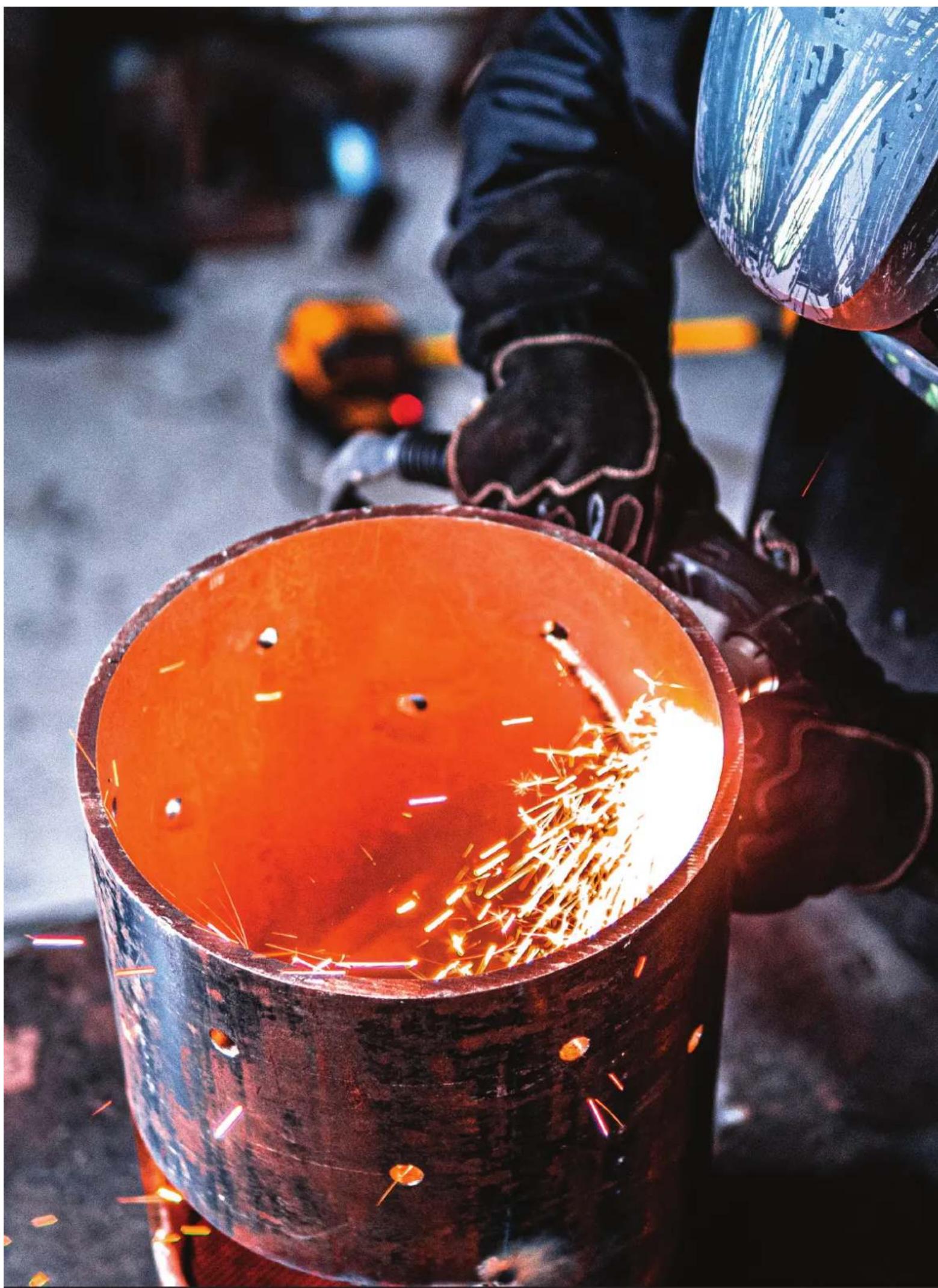
natural_image
Close-up of a worker welding metal with sparks flying, wearing protective gear (no visible text or symbols)
natural_image
Close-up of a car's front wheel and dashboard with green and black stripes (no visible text or symbols)CONTENTS
SAFETY 4
TECHNICAL DATA 7
MACHINE LAYOUT 8
WHAT'S IN THE BOX 10
GENERAL OPERATING TIPS 11
SETUP FOR INTERNAL AIR PLASMA CUTTING 12
SETUP FOR EXTERNAL AIR PLASMA CUTTING 15
PLASMA CUTTING TECHNOLOGY 19
PLASMA CUTTING TIPS & TECHNIQUES 20
TORCH BREAKDOWN & SPARES 22
Welding and cutting equipment can be dangerous to both the operator and people in or near the surrounding working area if the equipment is not correctly operated. Equipment must only be used under the strict and comprehensive observance of all relevant safety regulations.
Read and understand this instruction manual carefully before the installation and operation of this equipment.
WARNING: USE COMPRESSED AIR ONLY WITH THIS MACHINE
Machine Operating Safety
- Do not switch the function modes while the machine is operating. Switching of the function modes during welding can damage the machine. Damage caused in this manner will not be covered under warranty.
- Disconnect the electrode-holder cable from the machine before switching on the machine, to avoid arcing should the electrode be in contact with the workpiece.
- Operators should be trained and or qualified.
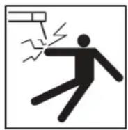
Electric shock: It can kill. Touching live electrical parts can cause fatal shocks or severe burns. The electrode and work circuit is electrically live whenever the output is on. The input power circuit and internal machine circuits are also live when power is on. In MIG/MAG welding, the wire, drive rollers, wire feed housing, and all metal parts touching the welding wire are electrically live. Incorrectly installed or improperly grounded equipment is dangerous.
- Connect the primary input cable, according to Australian and New Zealand standards and regulations.
- Avoid all contact with live electrical parts of the welding/cutting circuit, electrodes and wires with bare hands.
- The operator must wear dry welding gloves while he/she performs the welding/cutting task.
- The operator should keep the workpiece insulated from himself/herself.
- Keep cords dry, free of oil and grease, and protected from hot metal and sparks.
- Frequently inspect input power cable for wear and tear, replace the cable immediately if damaged, bare wiring is dangerous and can kill.
- Do not use damaged, undersized, or badly joined cables.
- Do not drape cables over your body.
• We recommend (RCD) safety switch is used with this equipment to detect any leakage of current to earth.
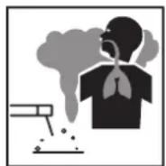
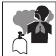
Fumes and gases are dangerous. Smoke and gas generated while welding or cutting can be harmful to people's health. Welding produces fumes and gases. Breathing these fumes and gases can be hazardous to your health.
- Do not breathe the smoke and gas generated while welding or cutting, keep your head out of the fumes.
- Keep the working area well ventilated, use fume extraction or ventilation to remove welding/cutting fumes and gases.
- In confined or heavy fume environments always wear an approved air-supplied respirator.
- Welding/cutting fumes and gases can displace air and lower the oxygen level, causing injury or death. Be sure the breathing air is safe.
- Do not weld/cut in locations near degreasing, cleaning, or spraying operations. The heat and rays of the arc can react with vapours to form highly toxic and irritating gases.
- Materials such as galvanised, lead, or cadmium plated steel, containing elements that can give off toxic fumes when welded/cut. Do not weld/cut these materials unless the area is very well ventilated, and or wearing an air-supplied respirator.
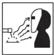
Arc rays: harmful to people's eyes and skin. Arc rays from the welding/cutting process produce intense visible and invisible ultraviolet and infrared rays that can burn eyes and skin.
- Always wear a welding helmet with the correct shade of filter lens and suitable protective clothing, including welding gloves while the welding/cutting operation is performed.
- Measures should be taken to protect people in or near the surrounding working area. Use protective screens or barriers to protect others from flash, glare and sparks; warn others not to watch the arc.
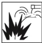
Fire hazard. Welding/cutting on closed containers, such as tanks, drums, or pipes, can cause them to explode.
Flying sparks from the welding/cutting arc, hot workpiece, and hot equipment can cause fires and burns.
Accidental contact of the electrode to metal objects can cause sparks, explosion, overheating, or fire. Check and be sure the area is safe before doing any welding/cutting.
- The welding/cutting sparks & spatter may cause fire, therefore remove any flammable materials well away from the working area. Cover flammable materials and containers with approved covers if unable to be moved from the welding/cutting area.
- Do not weld/cut on closed containers such as tanks, drums, or pipes, unless they are correctly prepared according to the required Safety Standards to ensure that flammable or toxic vapours and substances are totally removed, these can cause an explosion even though the vessel has been “cleaned”. Vent hollow castings or containers before heating, cutting or welding. They may explode.
- Do not weld/cut where the atmosphere may contain flammable dust, gas, or liquid vapours (such as petrol)
- Have a fire extinguisher nearby and know how to use it. Be alert that welding/cutting sparks and hot materials from welding/cutting can easily go through small cracks and openings to adjacent areas. Be aware that welding/cutting on a ceiling, floor, bulkhead, or partition can cause a fire on the hidden side.
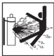
Gas Cylinders. Shielding gas cylinders contain gas under high pressure. If damaged, a cylinder can explode.
Because gas cylinders usually are part of the welding/cutting process, be sure to treat them carefully. CYLINDERS can explode if damaged.
- Protect gas cylinders from excessive heat, mechanical shocks, physical damage, slag, open flames, sparks, and arcs.
- Ensure cylinders are held secure and upright to prevent tipping or falling over.
- Never allow the welding/cutting electrode or earth clamp to touch the gas cylinder, do not drape welding cables over the cylinder.
- Never weld/cut on a pressurised gas cylinder, it will explode and kill you.
- Open the cylinder valve slowly and turn your face away from the cylinder outlet valve and gas regulator.
Gas build-up. The build-up of gas can cause a toxic environment, deplete the oxygen content in the air resulting in death or injury. Many gases use in welding/cutting are invisible and odourless.
- Shut off shielding gas supply when not in use.
• Always ventilate confined spaces or use approved air-supplied respirator.
Electronic magnetic fields. MAGNETIC FIELDS can affect Implanted Medical Devices.
- Wearers of Pacemakers and other Implanted Medical Devices should keep away.
- Implanted Medical Device wearers should consult their doctor and the device manufacturer before going near any electric welding, cutting or heating operation.

Noise can damage hearing. Noise from some processes or equipment can damage hearing.
- Wear approved ear protection if noise level is high.

Hot parts. Items being welded/cut generate and hold high heat and can cause severe burns.
- Do not touch hot parts with bare hands. Allow a cooling period before working on the welding/cutting gun. Use insulated welding gloves and clothing to handle hot parts and prevent burns.
CAUTION
1. Working Environment.
i. The environment in which this welding/cutting equipment is installed must be free of grinding dust, corrosive chemicals, flammable gas or materials etc., and at no more than a maximum of 80% humidity.
ii. When using the machine outdoors, protect the machine from direct sunlight, rainwater and snow, etc.; the temperature of the working environment should be maintained within -10^ to +40^ .
iii. Keep this equipment 30cm distant from the wall.
iv. Ensure the working environment is well ventilated.
2. Safety Tips.
i. Ventilation: This equipment is small-sized, compact in structure, and of excellent performance in amperage output. The fan is used to dissipate heat generated by this equipment during the welding/cutting operation. Important: Maintain good ventilation of the louvres of this equipment. The minimum distance between this equipment and any other objects in or near the working area should be 30 cm. Good ventilation is of critical importance for the normal performance and service life of this equipment.
ii. Thermal Overload Protection: Should the machine be used to an excessive level, or in a high-temperature environment, poorly ventilated area or if the fan malfunctions the Thermal Overload Switch will be activated, and the machine will cease to operate. Under this circumstance, leave the machine switched on to keep the built-in fan working to bring down the temperature inside the equipment. The machine will be ready for use again when the internal temperature reaches a safe level.
iii. Over-Voltage Supply: Regarding the power supply voltage range of the machine, please refer to the "Main parameter" table. This equipment is of automatic voltage compensation, which enables the maintaining of the voltage range within the given range. In case that the voltage of input power supply amperage exceeds the stipulated value, it is possible to cause damage to the components of this equipment. Please ensure your primary power supply is correct.
iv. Do not come into contact with the output terminals while the machine is in operation. An electric shock may occur.
MAINTENANCE
Exposure to extremely dusty, damp, or corrosive air is damaging to the welding/cutting machine. To prevent any possible failure or fault of this welding/cutting equipment, clean the dust at regular intervals with clean and dry compressed air of required pressure.
Please note that: lack of maintenance can result in the cancellation of the guarantee; the guarantee of this welding/cutting equipment will be void if the machine has been modified, attempt to take apart the machine or open the factory-made sealing of the machine without the consent of an authorized representative of the manufacturer.
TROUBLESHOOTING
Caution: Only qualified technicians are authorized to undertake the repair of this welding/cutting equipment. For your safety and to avoid Electrical Shock, please observe all safety notes and precautions detailed in this manual.
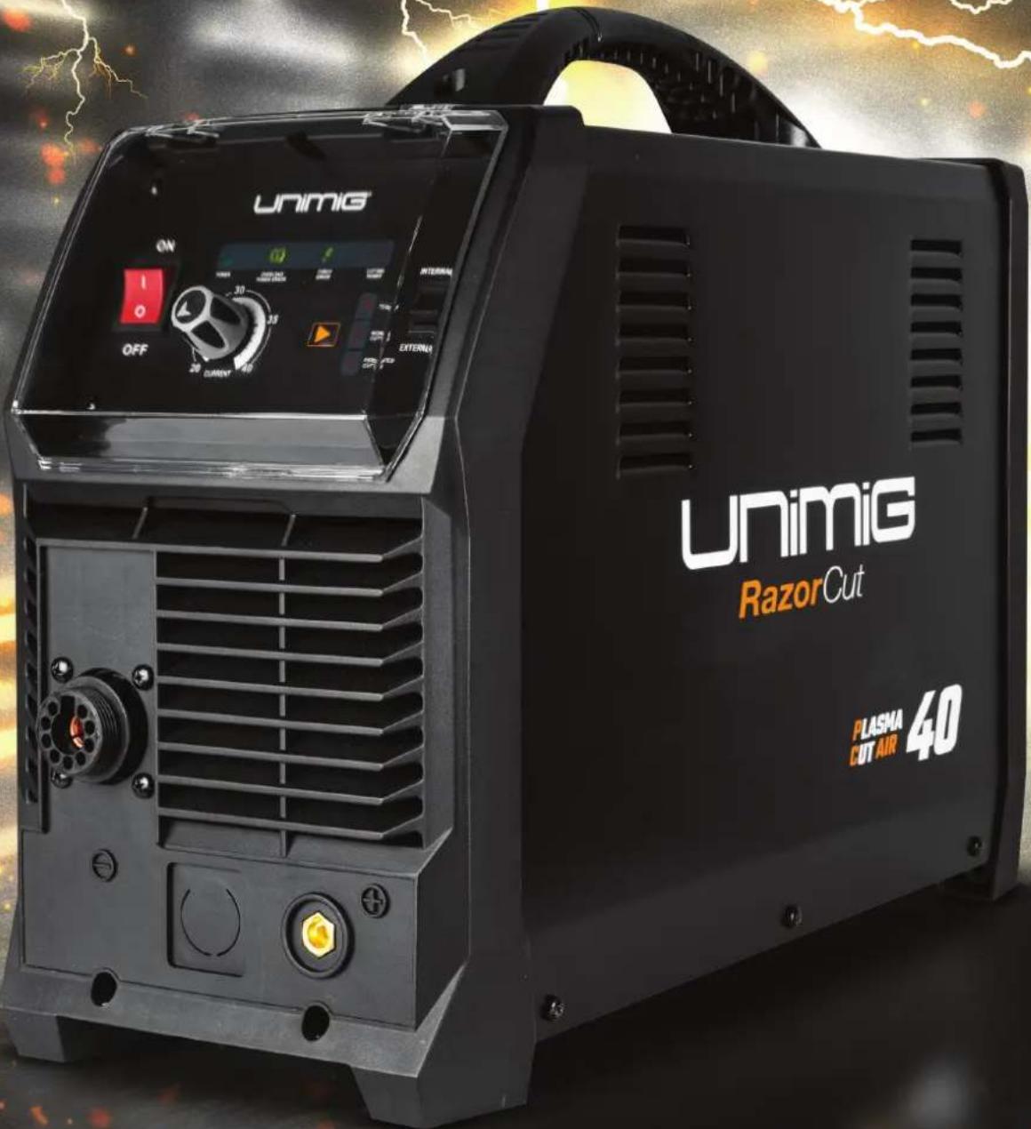
RAZOR™ CUT 40 AIR Plasma Cutter
Key Features:
• Built-in Air Compressor
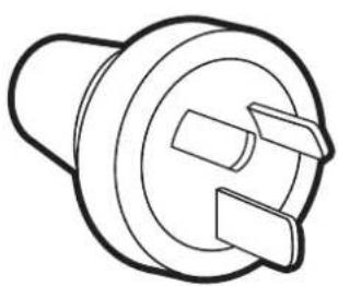
• 15 AMP Plug
- Pilot Arc Start
- 10mm Clean Cut
- 12mm Severance

natural_image
Exterior view of a UNiG RazorOut electric welding torch kit (no signage or text in focus)3YEAR PRODUCT WARRANTY
TECHNICAL DATA
| SKU U14001K |
| PRIMARY INPUT VOLTAGE 240V Single Phase |
| SUPPLY PLUG 15A |
| RATED INPUT POWER (kVA) 72 |
| RATED OUTPUT VOLTAGE (V) 96 |
| NO LOAD VOLTAGE (V) 210 |
| AIR FLOW DRAW OFF (L/min) 120 L/min |
| AIR FLOW PRESSURE (Bar) 5.17 (75 psi) |
| PROTECTION CLASS IP21 |
| INSULATION CLASS H |
| MINIMUM GENERATOR (kVA) 10.0 |
| DINSE CONNECTOR 10/25 |
| STANDARD AS/NZ60974-1 |
| WARRANTY (Years) 3 |
PLASMA CUT SPECIFICATIONS
| INTERNAL AIR EXTERNAL AIR | ||
| PLASMA CUT CURRENT RANGE 20-40A 20-40A | ||
| 25% @ 40A | 25% @ 40A | |
| PLASMA CUT DUTY CYCLE @ 40°C | 60% @ 26A | 60% @ 26A |
| 100% @ 20A | 100% @ 20A | |
| MILD STEEL CUT THICKNESS 10mm 16mm | ||
| MILD STEEL SEVERANCE THICKNESS 12mm 20mm | ||
| ALUMINIUM CUT THICKNESS 6mm 10mm | ||
| ALUMINIUM SEVERANCE THICKNESS 8mm 12mm | ||
| STAINLESS STEEL CUT THICKNESS 6mm 10mm | ||
| STAINLESS STEEL SEVERANCE THICKNESS 8mm 12mm | ||
SIZE & WEIGHT
| DIMENSIONS (mm) 610x215x420mm |
| WEIGHT (kg) 18.0kg |
MACHINE FEATURES
| PLASMA ARC START Pilot Arc |
| THERMAL OVERLOAD PROTECTION Over Temperature Warning |
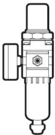
Recommended Accessories
natural_image
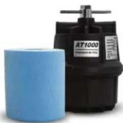
Two industrial equipment units, one blue and one black, with no visible text or symbols on the main components.Plasma Cutter Air Filter
50500
See page 21
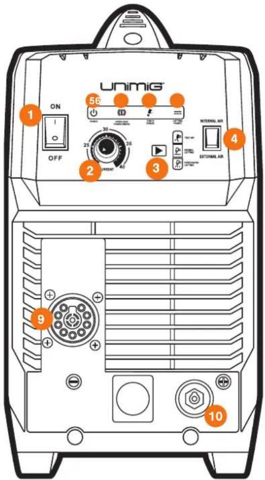
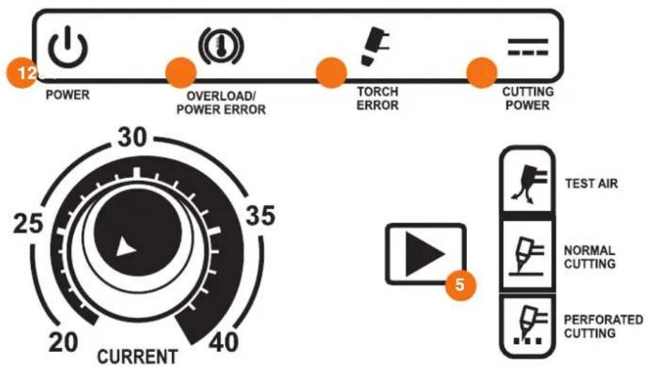
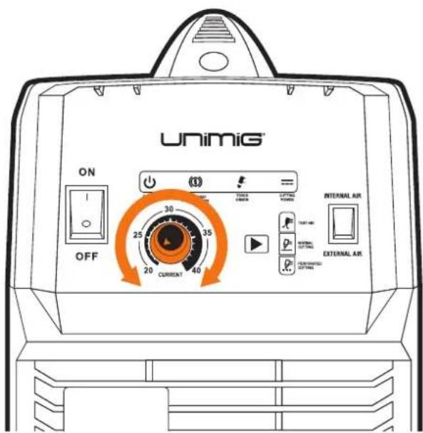
Front Panel Layout
- On/Off Power Switch
- Current Control Knob
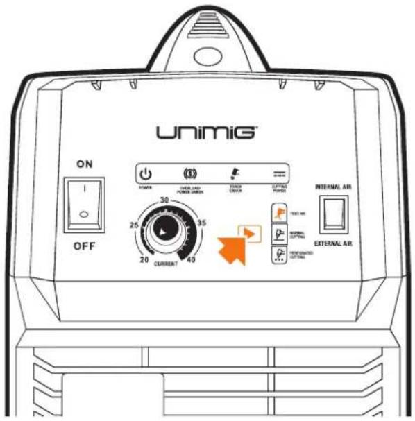
- Cut Mode Switch
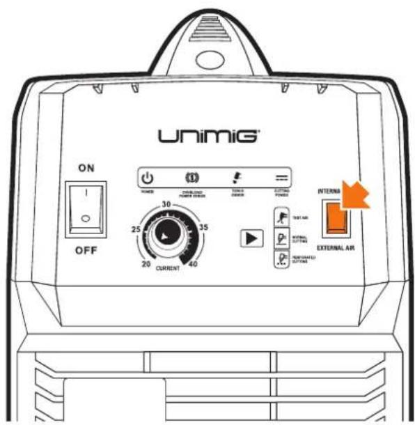
- Internal/External Air Switch
- Power LED
- Overload/Power Error LED
- Torch Error LED
- Cutting Power LED
- Plasma Torch Connection
- Earth Clamp Connection (10/25 Dinse)
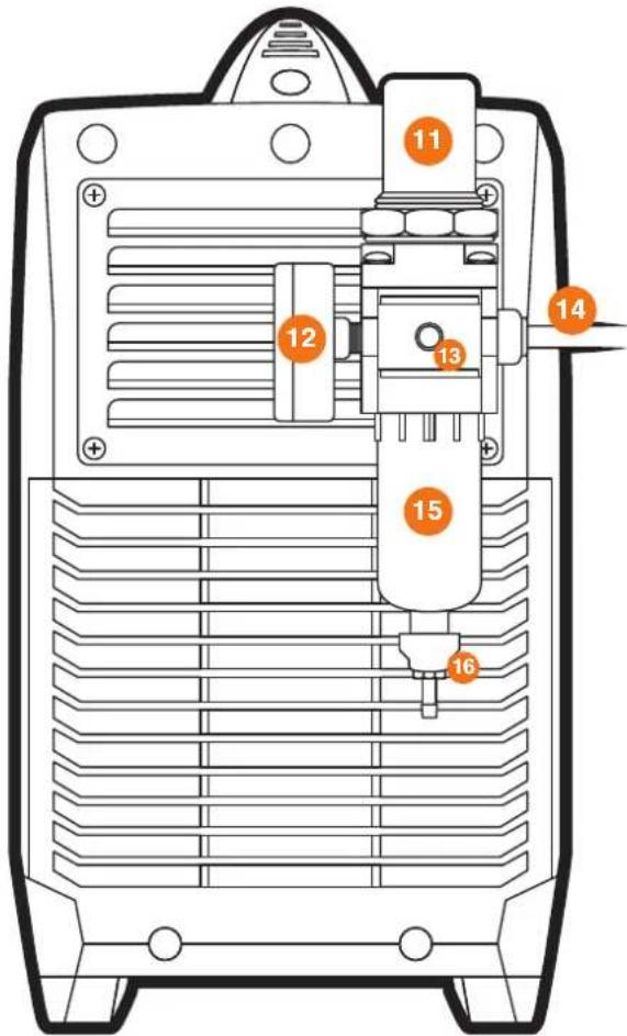
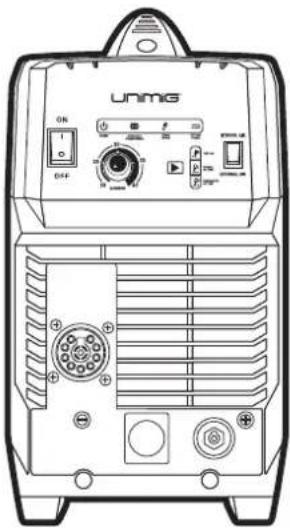
Rear Panel Layout
- Air Pressure Regulator Knob
- Air Pressure Regulator Outles Pressure Gauge
- Compressed Air Inlet / Gas Inlet Connector
- Mains Power Cable
- Air Condensate Filter / Trap
- Air Condensate Filter Drain Tube
Additional Machine Control Information
1. Power LED
- Lights up when input power connected and the machine switched on.
2. Overload / Power Error LED
- Lights up when over-voltage, over-current or electrical overheating (due to exceeding duty cycle) is detected and protection is activated. When protection is activated, cutting output will be disabled until the safety system senses the overload has reduced sufficiently, and the indicator LED goes out. May also trigger if the machine experiences an internal power circuit failure.
3. Torch Error LED
- Lights up when an issue with the torch system or air supply detected and cutting output is disabled as a result. Flashing light means that the torch shield cap is not installed. Continuous light means likely damaged or missing torch consumables or insufficient air pressure supply to the torch.
4. Cutting Power LED
- Lights up when cutting power circuit activated.
5. Cut Mode Switch
- When positioned as "Test Air", the compressed air control valve is open continuously. This is useful for testing and setting the air pressure without having to activate the trigger circuit.
- "Normal Cutting" is the standard cutting mode, for use with solid workpieces.
- “Perforated Cutting” is the cutting mode when cutting a perforated workpiece.
RAZOR CUT 40 AIR Plasma Cutter
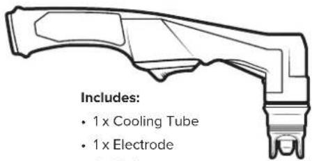
- 1x Cooling Tube
- 1x Electrode
- 1 x O ring
- 1x Cutting Tip
- 1x Retaining Cap
- 1 x Stand Off Guide
6m SC80 Plasma Torch

natural_image
Line drawing of a pair of pliers with metal fasteners (no text or symbols)4m 300 AMP Earth Clamp
natural_image
Technical line drawing of a mechanical pressure relief device (no text or symbols)Air Regulator
natural_image
Line drawing of a mechanical component with no text or symbols15 AMP Plug (Fitted)

Operating Manual
Additional Machine Control Information
Compressed Air Requirements
A reliable and consistent supply of clean, dry compressed air is essential for proper operation. Although the machine contains its own internal air supply filtration system it is recommended the compressed air supply should have external filtration in the line feeding the machine, both a standard water trap (sintered bronze filter) and also a coalescing filter (for oil in the air). The air requirement is a minimum of 120 L/min (4.5cfm) Free Air Delivery (FAD) at 75psi pressure. This usually means the compressor must be a belt-drive model or if a direct drive, it must have a motor power of 2.5HP or higher.
The air must be dry and free of oil and moisture (usually a symptom of older, worn-out compressors). The air hose must also be of sufficient size (3/8"/10mm minimum) to supply the machine.
Operation environment
• Height above sea level ≤1000 M
• Operation temperature range -10 to +40°C
• Air relative humidity is below 90 % (20°C)
- Preferably sit the machine some angles above the floor level, the maximum angle does not exceed 15.
- Protect the machine against heavy rain AND against direct sunshine.
- The content of dust, acid, corrosive gas in the surrounding air or substance cannot exceed the normal standard.
• Take care that there is sufficient ventilation during plasma cutting. There must be at least 30cm free distance between the machine and wall.
Operation Notices
- Read this manual carefully before starting to use this equipment.
- Connect the ground wire with the machine directly.
- Ensure that the input is single-phase: 50/60Hz, 240V ±10%.
- Before operation, clear all unnecessary personal from the work area.
- Do not watch the arc in unprotected eyes.
- Ensure proper ventilation of the machine to improve the Duty Cycle.
- Turn off the machine when the operation finished for energy consumption efficiency.
- When the power switch shuts off protectively because of failure, don't restart it until the problem is resolved. Otherwise, the range of the problem will be extended.
• In case of problems, contact your local dealer if no authorized maintenance staff is available
SETUP FOR INTERNAL AIR PLASMA CUTTING
1 Connect the plasma torch to the plasma torch connection. Tighten the nut once connected to ensure a secure connection.
2 Connect the earth clamp to the positive (+) dinse connection, twist to lock in place

natural_image
Line drawing of a UNiG Razor Cut electric shock absorber with attached probe and cable (no text or symbols on device body)3 Connect the plug into a 15 AMP socket, then switch the machine ON.
4 Select INTERNAL air supply.

5 Select Test Air by pressing the Cut Mode Mode button until the Test Air icon lights up, to check that air is feeding correctly.
6 Connect the earth clamp to the work piece.
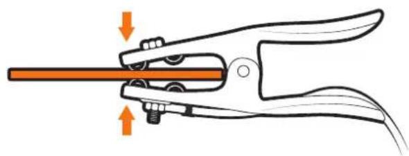
natural_image
Illustration of a pliers gripping a tool with orange arrows indicating force or movement (no text or symbols)7 Select desired cutting mode by pressing the Cut Mode Mode button until the desired cutting mode up.
8 Set the current to turning the Current Control Knob.
SETUP FOR INTERNAL AIR PLASMA CUTTING
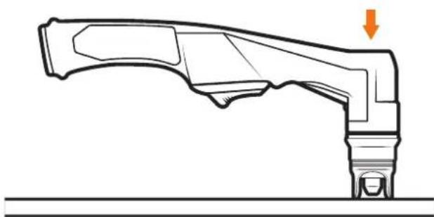
9 Place and hold the torch vertical at the edge of the plate.
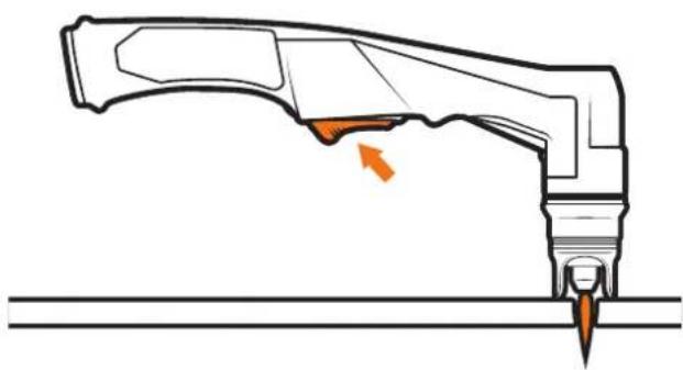
10 Pull the trigger to energise the arc. When the cutting arc has cut through the edge of the plate start moving evenly in the direction you wish to cut.

natural_image
Technical line drawing of a mechanical component with an arrow indicating direction (no text or symbols present)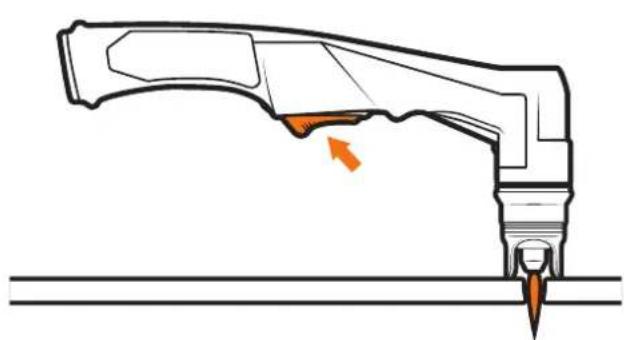
natural_image
Technical line drawing of a mechanical component with an arrow indicating a specific feature (no text or symbols present)11 To finish the cutting release the torch switch. The air flow will continue for 30 seconds to cool the torch head. Do not disconnect air until this cooling period has been completed. Failure to do this will result in torch head damage.
natural_image
Technical line drawing of a mechanical component with orange arrows indicating motion or force direction (no text or symbols)SETUP FOR EXTERNAL AIR PLASMA CUTTING
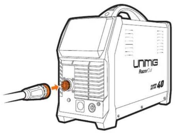
1 Connect the plasma torch to the plasma torch connection. Tighten the nut once connected to ensure a secure connection.
2 Connect the earth clamp to the positive (+) dinse connection, twist to lock in place

natural_image
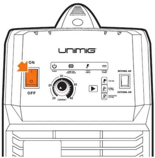
Line drawing of a UNiG Razor Cut electric shock absorber with attached probe and cable (no text or symbols on device body)3 Connect the plug into a 15 AMP socket, then switch the machine ON.
4 Select EXTERNAL air supply.

WARNING: USE COMPRESSED AIR ONLY WITH THIS MACHINE
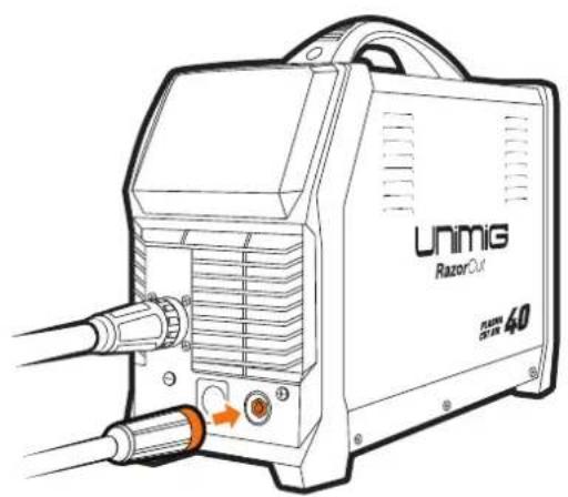
5 Connect air supply to the Air Filter.
natural_image
Technical line drawing of a mechanical device with ventilation grilles and a tool inserted (no text or symbols)6 Select Test Air by pressing the Cut Mode Mode button until the Test Air icon lights up.
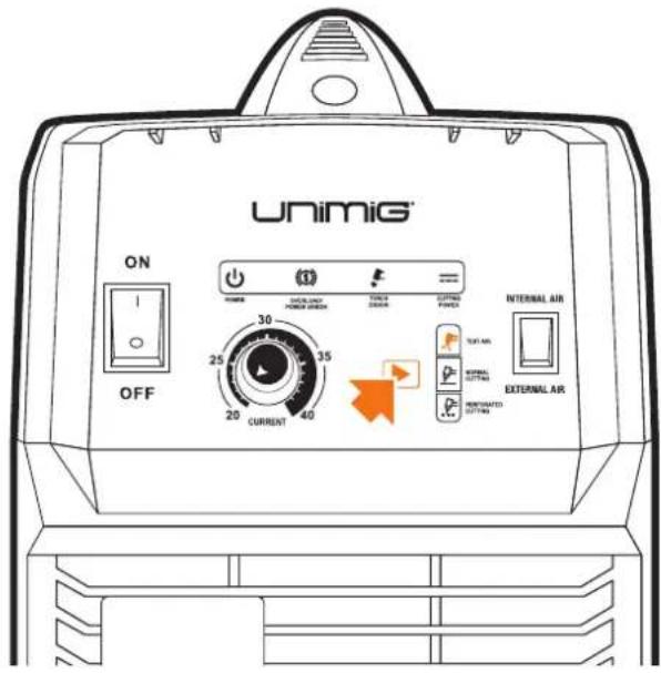
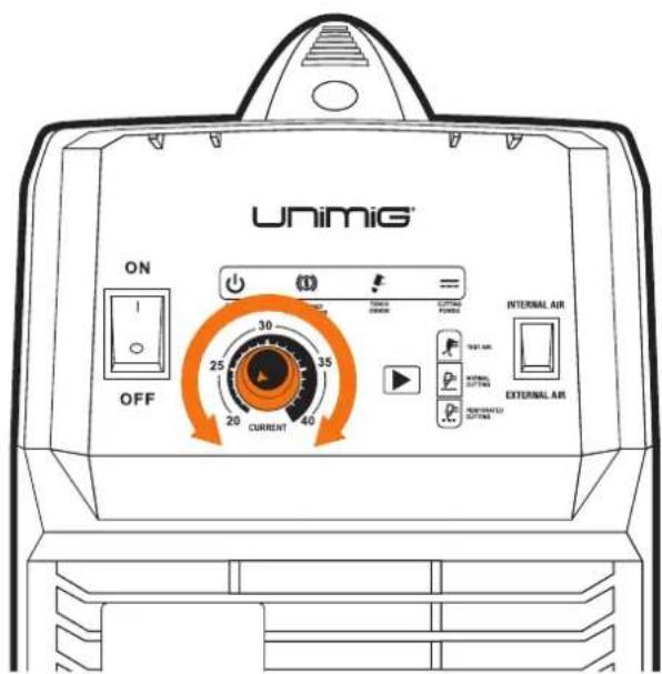
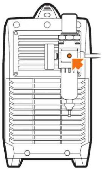
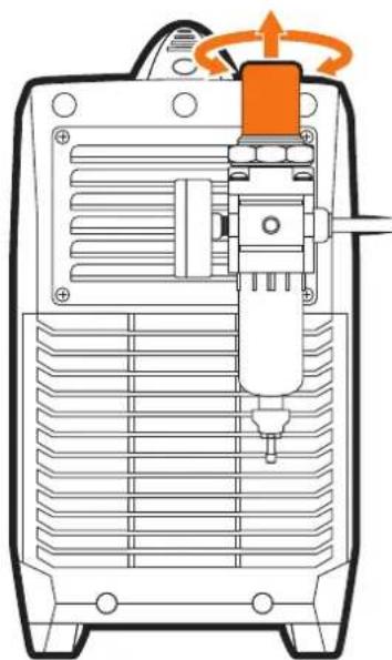
7 Lift the Air Pressure Regulator Knob, then turn the knob until you reach an ideal reading of 0.5MPa (75psi).
natural_image
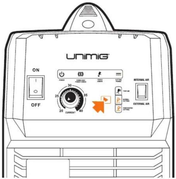
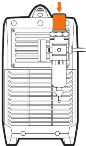
Technical line drawing of a mechanical device with internal components and a rotating knob (no text or symbols)8 Push the Air Pressure Regulator Knob downwards to lock the reading in place.
natural_image
Technical diagram of a mechanical device with a highlighted component and orange arrow indicating direction (no text or symbols)SETUP FOR EXTERNAL AIR PLASMA CUTTING
9 Connect the earth clamp to the work piece.

natural_image
Illustration of a pliers gripping a tool with orange arrows indicating force or movement (no text or symbols)10 Select desired cutting mode by pressing the Cut Mode button until the desired cutting mode up.
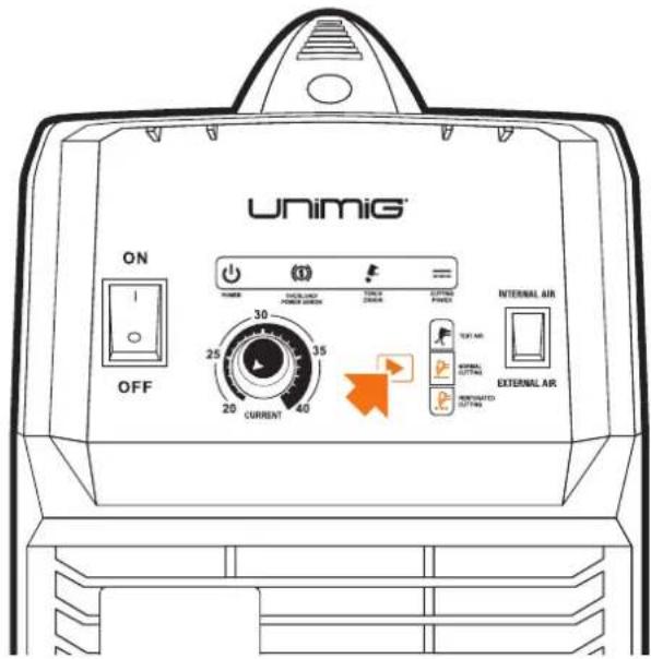
11 Set the current to turning the Current Control Knob.
12 Place and hold the torch vertical at the edge of the plate.
natural_image
Technical line drawing of a mechanical component with an arrow indicating direction (no text or symbols present)SETUP FOR EXTERNAL AIR PLASMA CUTTING

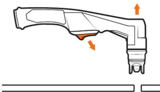
Pull the trigger to energise the arc. When the cutting arc has cut through the edge of the plate start moving evenly in the direction you wish to cut.

To finish the cutting release the torch switch. The air flow will continue for 30 seconds to cool the torch head. Do not disconnect air until this cooling period has been completed. Failure to do this will result in torch head damage.
natural_image
Technical line drawing of a mechanical component with an arrow indicating a specific feature (no text or symbols present)
natural_image
Technical line drawing of a mechanical component with orange arrows indicating features (no text or symbols)Plasma cutters work by passing an electric arc through a gas that is passing through a constricted opening. The electric arc elevates the temperature of the gas to the point that it enters a 4th state of matter. We all are familiar with the first three: i.e., Solid, liquid, and gas. Scientists call this additional state plasma. As the metal being cut is part of the circuit, the electrical conductivity of the plasma causes the arc to transfer to the work. The restricted opening (Tip) the gas passes through causes it to squeeze by at high speed, like air passing through a venturi in a carburettor. This high-speed gas cuts through the molten metal. Plasma cutting was invented as a result of trying to develop a better welding process. Many improvements then led to making this technology what it is today. Plasma cutters provide the best combination of accuracy, speed, and affordability for producing a variety of flat metal shapes. They can cut much finer and faster than oxy-acetylene torches.
How a plasma cutter works:
Basic plasma cutters use electricity to superheat air into plasma (the 4th state of matter), which is then blown through the metal to be cut. Plasma cutters require a compressed air supply and AC power to operate.
Operation:
- When the trigger is squeezed, DC current flows through the torch lead into the tip.
- Next, compressed air flows through the torch head, through the air diffuser that spirals the airflow around the electrode and through the hole of the cutting tip.
- A fixed gap is established between the electrode and the tip. (The power supply increases voltage in order to maintain a constant current through the joint.) Electrons arc across the gap, ionizing and superheating the air creating a plasma stream.
- Finally, the regulated DC current is switched so that it no longer flows to the tip but instead flows from the electrode to the workpiece. Current and airflow continue until cutting is stopped.
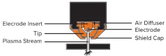
The nozzle and electrode require periodic replacement. The electrode has an insert of a tough high conductive material such as hafnium and cerium. This insert erodes with use; also, the tip orifice will erode with use. Quality of the air used is paramount to longer life of electrodes and tips, in short, clean dry air gives more extended parts life, the cleaner and dryer the better. We recommend the use of a Plasma Air Filter.
What kinds of materials can the plasma cut?
Virtually any metal can be plasma cut including steel, stainless steel, aluminium, brass, copper, etc. Any thickness from 30 gauge through 30mm can be cut, depending on the power of the plasma cutter used.
How Does Plasma Cutting Compare to Oxy-fuel (gas) cutting?
Plasma cutting can be performed on any conductive metal - mild steel, aluminium and stainless are some examples. With mild steel, operators will experience faster, thicker cuts than with alloys.
Oxy-fuel cuts by burning, or oxidizing the metal it is severanceing. It is therefore limited to steel and other ferrous metals which support the oxidizing process. Metals like aluminium and stainless steel form an oxide that inhibits further oxidization, making conventional oxy-fuel cutting impossible. Plasma cutting, however, does not rely on oxidation to work and thus it can cut aluminium, stainless and any other conductive material. While different gasses can be used for plasma cutting, most people today use compressed air for the plasma gas. In most shops, compressed air is readily available, and thus plasma does not require fuel gas and compressed oxygen for operation.
Plasma cutting is typically more accessible for the novice to master, and on thinner materials, plasma cutting is much faster than oxy-fuel cutting. However, for heavy sections of steel (25mm and greater), oxy-fuel is still preferred since oxy-fuel is typically faster and, for heavier plate applications, high powered plasma machines are required for plasma cutting applications.
What are the limitations to Plasma Cutting? Where is Oxy-fuel preferred?
The plasma cutting machines are typically more expensive than oxy/acetylene. Also, oxy/acetylene does not require access to electrical power or compressed air which may make it a more convenient method for some users. Oxy-fuel can generally cut thicker sections (>25mm) of steel more quickly than plasma.
Amperage
The standard rule of thumb is the thicker the material, the more amperage required. On thick material, set the machine to full output and vary your travel speed. On thinner material, you need to turn down the amperage and change to a lower-amperage tip to maintain a narrow kerf. The kerf is the width of the cut material that is removed during cutting.
Speed
Amperage and speed are critical to producing a good quality cut. The faster you move (especially on aluminium), the cleaner your cut will be. To determine if you're going too fast or too slow, visually follow the arc that is coming from the bottom of the cut. The arc should exit the material at a slight angle away from the direction of travel. If it's going straight down, that means you're going too slow, and you'll have an unnecessary build-up of dross or slag. If you go too fast, it will start spraying back onto the surface of the material without cutting all the way through. Because the arc trails at an angle, at the end of a cut, slow your cutting speed and angle the torch in to cut through the last bit of metal.
Direction
It is easier to pull the torch towards you than push it. The plasma stream swirls as it exits the tip, biting one side and finishing off on the other, leaving a bevelled edge and a straight edge. The bevel cut effect is more noticeable on thicker material and needs to be taken into consideration before starting your cut as you want the straight side of the cut to be on the finished piece you keep.
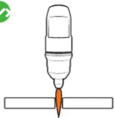
Torch tip height & position
The distance and position of the plasma torch cutting tip affect the quality of the cut and the extent of the bevel of the cut. The easiest way to reduce bevel is by cutting at the proper speed and height for the material and amperage that is being cut.

natural_image
Simple line drawing of a pen tip pressing into a rectangular block (no text or symbols)Correct torch height and square to the material. Minimum bevel & equal bevel Longest consumable life.

natural_image
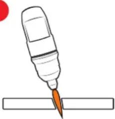
Simple line drawing of a pen tip cutting into a rectangular block (no text or symbols)Torch angled to the material. Unequal bevel, one side may be excessively bevelled.

natural_image
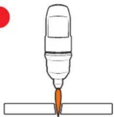
Simple line drawing of a pen tip inserted into a rectangular base, with no text or symbols present.Torch height too high. Excessive bevel, plasma stream may not cut all the way through the material.

natural_image
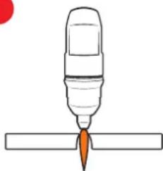
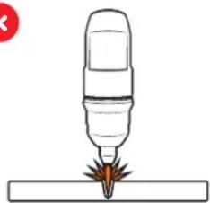
Simple line drawing of a pen tip with a flame, placed above a horizontal surface (no text or symbols)Torch height too low. Reverse bevel. The tip may contact the work and short out or damage the tip.

natural_image
Illustration of a precision tool tip emitting sparks onto a surface (no text or symbols)If sparks are spraying up from the work piece, you are moving the torch too fast, or you don't have enough amps set.
Tip size and condition
The tip orifices focus the plasma stream to the workpiece. It is essential to use the correct size tip for the amperage being used, for example, a tip with a 1.0mm orifice is suitable for 0-40 amps whereas a 1.3mm orifice is better for 40-80 amps. The low-amp tip has a smaller orifice which maintains a narrow plasma stream at lower settings for use on thin-gauge material. Using a 25 amp tip at a 60 amp setting will blow out and distort the tip orifice and require replacement. Conversely, using an 80-amp tip on the lower settings will not allow you to focus the plasma stream as well and creates a wide kerf. The condition of the tip orifice is critical to the quality of the cut result, a worn or damaged tip orifice will produce a distorted plasma stream resulting in poor cut quality.
Electrode condition
A fixed gap is established between the electrode and the inside of the cutting tip — electrons arc across the gap, ionizing and superheating the air creating the plasma stream. The electrode contains an insert at the end made of a highly conductive material called hafnium. This insert erodes with use and develops a pit at the end of the electrode when the pit becomes too much poor-quality cuts will result and necessitate replacement of the electrode.
Air pressure and volume
Air pressure, flow rate and air quality are critical to quality plasma cutting and consumable life span. The required air pressure and volume can vary from model to model, and the manufacturer will provide the specs.
The RAZOR CUT 40 AIR air pressure must be adjusted and set to 0.5MPA (75psi) and requires a flow rate of 120 L/min. The volume capacity of your compressor is important. If you have a small compressor with precisely the same L/min rating as the plasma, then the compressor will run continuously when you are plasma cutting. A compressor with a L/min rating slightly higher than the plasma would be more than adequate.
If you are doing a lot of cutting, cutting thick plate (same air consumption but slower cut speeds = longer cut time), then choose a compressor at 1.5 to 2 times the plasma system requirement.
Air quality
Good, dry air is essential to quality plasma cutting and consumable life span.
Compressors take in air at atmospheric pressure and increase the pressure and store it in a tank. Humidity in the air is condensed in the tank and the airlines producing water, more so in humid environments. Moisture that forms in airlines tends to condense into larger drops when the air pressure decreases as it is entering the plasma torch. When these droplets enter into the high temperatures (as much as 11,000°C) in the plenum of the torch, they immediately break down into oxygen and hydrogen, which alters the regular chemical content of the air in the torch. These elements will then dramatically change the plasma arc which causes the torch consumable parts to wear very quickly, alters the shape of the nozzle orifice, dramatically affecting cut quality in terms of edge squareness, dross formation, and edge smoothness.
Minimising the moisture in the air supply is absolutely critical to quality plasma cuts and longevity of consumable parts. As a minimum be sure to drain the receiver (tank) on the air compressor at least daily.
Most air plasma systems from reputable manufacturers have an onboard particulate filter and or a coalescing filter with an auto drain that will remove some moisture from the air supply. For home workshop and light industrial users, the onboard air filter is adequate. Most situations, however, will require additional filtration to prevent moisture from affecting the quality of the plasma cutter and in most cases, it is recommended to install a submicronic particulate filter that is designed to trap water through absorption. This style of filter has a replaceable filter cartridge that absorbs water and must be changed after it is near saturation; it should be installed close as possible to the air intake of the plasma cutter.
General Tips
- It is easier to pull the torch through the cut than to push it.
- To cut thin material, reduce the amperage until you get the best quality cut.
- Use the correct size tip orifice for the amperage being used.
- For straight cuts use a straight edge or cutting buggy as a guide. For circles, use a template or circle cutting attachment.
- Check that the front end consumable parts of the plasma cutting torch are in good condition.

natural_image
Exterior view of a black AT1000 air filter unit and a blue cylindrical component (no visible text or symbols on the device itself)Plasma Cutter Air Filter
SKU: 50500
Most situations, however, will require additional filtration to prevent moisture from affecting the quality of the plasma cutter and in most cases, it is recommended to install a submicronic particulate filter that is designed to trap water through absorption.
SC80 Plasma Torch
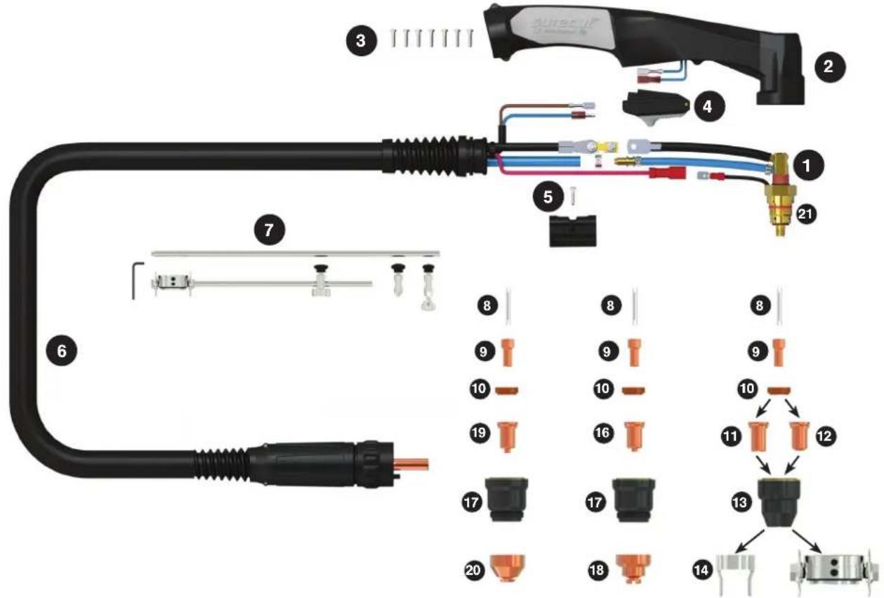
Contact CuttingGouging Stand Off Cutting
Length 6m
SKU WG-SC80-60-CC1
TORCH SPARES
| 1 SC8001 SC80 70 Torch Head Kit | ||
| 2 SC8014 Plasma Handle Kit | ||
| 3 SCSP1 Screw Pack | ||
| 4 SC2516 Plasma Safety Trigger | ||
| 5 SC8015 Location Block | ||
| 6 SC8019-60-CF4 Cable Assembly Complete X 6mt | ||
| 7 SC8050 | Circle Cutting Attachment Kit | |
| 8 SC8002 | Cooling Tube | |
| 9 PSC8004 | Electrode | |
| 10 SC8006 | Swirl Ring | |
| 11 PSC8020-09 | Cutting Tip 0.9mm | |
| 12 PSC8020-10 | Cutting Tip 1.0mm 40-50A | |
| PSC8020-13 | Cutting Tip 1.3mm 70-80A | |
| 13 SC8030 | Retaining Cup | |
| 14 SC8040 | Stand Off Guide | |
| 15 SC8051 Cutting Buggy | ||
| 16 PSC8026-10 | Cutting Tip Contact 1.0mm | |
| PSC8026-11 | Cutting Tip Contact 1.1mm | |
| PSC8026-12 | Cutting Tip Contact 1.2mm | |
| PSC8026-13 | Cutting Tip Contact 1.3mm | |
| 17 SC8031 Shield Cap Body | ||
| 18 SC8041 Shield Cap | ||
| 19 PSC8028-16 | Gouging Tip 1.6mm | |
| 20 SC8043 | Shield Cap Gouging | |
| 21 SC2508 | O Ring | |
TECHNICAL DATA
| COOLING METHOD | Air Cooled |
| DUTY CYCLE | 60% @ 80A |
| CUTTING THICKNESS | 20-25mm |
| GAS | Air/N2 |
| GAS PRESSURE | 4.5-5.0 Bar / 65-75 psl |
| GAS FLOW | 110L/min |
| IGNITION | Pilot Arc |
| POST FLOW | 90s |
| LENGTHS (m) | 6 |
| STANDARD | EN60974-7 |
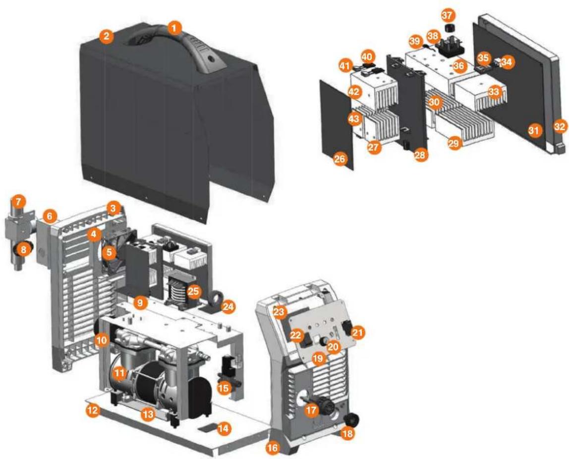
MACHINE SPARES
| 17.2530.004 Handle |
| 2 7.3010.0705 machine cabinet |
| 3 7.0680.921 rear plastic panel |
| 4 7.1220.0705 fixing plate for fan |
| 5 6.7200.006-A fan |
| 6 7.3070.0705 fixing sealing plate for rear panel |
| 7 6.2530.201 Oil water separator |
| 8 6.1550.003 fixing clamp for power cable |
| 9 3.0628.7011 EMC PCB |
| 10 7.1230.067 Holder for power block |
| 11 6.7210.001 pump |
| 12 7.0550.0705 bottom plate |
| 13 7.1230.066 fixing plate for pump |
| 14 3.0628.7025 Switch PCB for pump |
| 15 6.2530.101 Two position three-way solenoid valve |
| 16 7.0690.921 front plastic panel |
| 17 6.6670.002 control socket |
| 18 6.1520.001-A socket |
| 19 7.3060.0705 fixing plate for front control pcb |
| 20 6.4580.001 knob |
| 21 6.2320.201 Switch |
| 22 6.2320.001 Switch |
MACHINE SPARES
| 23 | 3.P628.4026-E | Digital display PCB |
| 3.0628.1038-C | Control PCB | |
| 24 | 3.0628.7003 | Inductance output PCB |
| 25 | 5.1850.0705 | main transformer |
| 26 | 3.0628.6002 | FRD PCB |
| 27 | 7.4230.031 | Heat sink for FRD |
| 28 | 7.7130.907 | Middle block plate |
| 29 | 7.4220.089 heat sink | |
| 30 | 7.4220.088 heat sink | |
| 31 | 3.0628.2004 | main PCB |
| 32 | 7.1230.932 sealing box for main PCB | |
| 33 | 7.4220.087 heat sink | |
| 34 | 7.7130.001 | Insulation sheet |
| 35 | 6.4250.004 IGBT | |
| 36 | 7.4220.086 heat sink | |
| 37 | 6.6620.001 Screw cover buckle | |
| 38 | 6.4110.003 | rectifier bridge |
| 39 | 6.2310.002-A | thermo resistor |
| 40 | 6.4010.001 | fast recovery diode |
| 41 | 7.7130.007 | insulation plate |
| 42 | 7.4230.029 heat sink for FRD | |
| 43 | 7.4230.030 heat sink for FRD | |
WARNING: There are extremely dangerous voltage and power levels present inside this unit. Do not attempt to diagnose or repair unit by removing external cover unless you are an authorised repair agent for UNIMIG.
1. Power lamp and temperature lamp on.
- Airflow blocked, check for blocked airflow around the unit and correct condition.
• Fan blocked, check and correct condition. - Unit is overheated, let the unit cool down for at least 5 minutes. Make sure the unit has not been operated beyond Duty Cycle limit.
- Faulty components in the unit, return for repair or have qualified technician repair per Service Manual.
2. Torch fails to ignite the arc when the torch switch is activated
- The system is in SET mode, change to RUN mode.
- Faulty torch parts, inspect torch parts and replace if necessary.
- Gas pressure too high or too low, adjust to the proper pressure.
- Faulty components in the unit, return for repair or have qualified technician repair per Service Manual.
3. No cutting output; Torch activated, power source on; Gas flows; Fan operates
- Torch not correctly connected to the machine, check that torch leads are correctly connected to the machine.
- Work cable not connected to the workpiece, or connection is weak, make sure that work cable has a proper connection to a clean, dry area of the workpiece.
- Faulty components in the unit, return for repair or have qualified technician repair per Service Manual.
- Faulty torch, return for repair or have qualified technician repair.
4. Low cutting output
- Incorrect setting of CURRENT (A) control, check and adjust to the proper setting.
- Faulty components in the unit, return for repair or have qualified technician repair.
5. Difficult Starting
- Worn torch parts (consumables), shut off input power. Remove and inspect torch shield cup, tip and electrode. Replace electrode or tip if worn; replace shield cup if excessive spatter adheres to it.
6. Arc shuts off during operation; arc will not restart when the torch switch is activated.
- Power Supply is overheated, let the unit cool down for at least 5 minutes. Make sure the unit has not been operated beyond Duty Cycle limit. Refer to Section 2 for duty cycle specifications.
- Gas pressure too low, check the source for at least 4bar/60psi; adjust as needed. It is needed to open the machine cover.
- Torch consumables worn, check torch shield cup, tip, starter element, and electrode; replace as needed.
- Faulty components in the unit, return for repair or have qualified technician repair per Service Manual.
7. No gas flow; the power lamp on; Fan operates
- Gas not connected or pressure too low, check gas connections. Adjust gas pressure to the proper setting
8. Torch cuts but low quality
- Current (A) control set too low, increase the current setting.
- The torch is being moved too fast across the workpiece, reduce cutting speed.
- Excessive oil or moisture in torch, hold torch 1/8 inch (3 mm) from a clean surface while purging and observe oil or moisture build-up (do not activate torch). If there are contaminants in the gas, additional filtering may be needed.
NOTES
unimig®
BUILT FOR WELDERS
HEAD OFFICE:
112 Christina Rd,
Villawood NSW 2163
PH: (02) 9780 4200
FAX: (02) 9780 4210
EMAIL: sales@unimig.com.au
QLD OFFICE:
180 Kerry Rd,
Archerfield QLD 4108
PH: (07) 3333 2855
FAX: (07) 3274 5829
EMAIL: qld@unimig.com.au
VIC OFFICE:
91 Yellowbox Drive,
Craigieburn VIC 3064
PH: (03) 8682 9911
FAX: (03) 9333 7867
EMAIL: vicsales@unimig.com.au
WA OFFICE:
Unit 2/29 Biscayne Way,
Jandakot WA 6164
PH: (08) 6363 5111
FAX: (08) 9417 4781
EMAIL: wasales@unimig.com.au
- 3YEAR PRODUCT WARRANTY
- Unimig®
- RAZOR CUT 40 AIR
- CONTENTS
- WARNING: USE COMPRESSED AIR ONLY WITH THIS MACHINE
- Machine Operating Safety
- CAUTION
- Working Environment.
- Safety Tips.
- MAINTENANCE
- TROUBLESHOOTING
- RAZOR™ CUT 40 AIR Plasma Cutter
- Key Features:
- Recommended Accessories
- Front Panel Layout
- Rear Panel Layout
- Additional Machine Control Information
- Power LED
- Overload / Power Error LED
- Torch Error LED
- Cutting Power LED
- Cut Mode Switch
- Compressed Air Requirements
- Operation environment
- Operation Notices
- SETUP FOR INTERNAL AIR PLASMA CUTTING
- SETUP FOR EXTERNAL AIR PLASMA CUTTING
- How a plasma cutter works:
- Operation:
- What kinds of materials can the plasma cut?
- How Does Plasma Cutting Compare to Oxy-fuel (gas) cutting?
- What are the limitations to Plasma Cutting? Where is Oxy-fuel preferred?
- Amperage
- Speed
- Direction
- Torch tip height & position
- Tip size and condition
- Electrode condition
- Air pressure and volume
- Air quality
- General Tips
- Plasma Cutter Air Filter
- Power lamp and temperature lamp on.
- Torch fails to ignite the arc when the torch switch is activated
- No cutting output; Torch activated, power source on; Gas flows; Fan operates
- Low cutting output
- Difficult Starting
- Arc shuts off during operation; arc will not restart when the torch switch is activated.
- No gas flow; the power lamp on; Fan operates
- Torch cuts but low quality
- NOTES
Brand : UNIMIG
Model : RAZOR CUT 40 Air
Category : Welding machine