SL-2 - Audio recorder Sound Devices - Free user manual and instructions
Find the device manual for free SL-2 Sound Devices in PDF.

| Product Type | 2-Channel Audio Recorder |
| Brand | Sound Devices |
| Model | SL-2 |
| Dimensions (W x H x D) | 5.7 x 3.3 x 2.2 in (145 x 84 x 56 mm) |
| Weight | 1.2 lb (544 g) without batteries |
| Power Source | 4 AA batteries (NiMH or alkaline) or USB-C DC input |
| Battery Life | Up to 5 hours with alkaline, up to 8 hours with NiMH |
| Recording Media | SD, SDHC, SDXC up to 512 GB |
| Audio Inputs | 2 x XLR-1/4" combo jacks |
| Analog Inputs | 2 x XLR-1/4" combo, +48V phantom power |
| Audio Outputs | 1 x 1/4" headphone output |
| Recording Format | WAV, MP3, 16/24-bit, 44.1/48/96 kHz |
| Maximum Input Level | +20 dBu |
| Frequency Response | 20 Hz – 20 kHz (±0.5 dB) |
| Preamp Equivalent Input Noise | -127 dBu, A-weighted |
| Dynamic Range | 108 dB (A-weighted) |
| Controls | Volume knob, record button, menu navigation |
| Display | OLED screen with waveform display |
| Mounting | 1/4"-20 tripod mount |
| Maintenance | Clean with a soft, dry cloth; avoid solvents |
| Safety | Do not expose to rain or moisture; use only specified power |
| Spare Parts | Contact authorized Sound Devices dealer for replacement parts |
| Repairability | Repairs should be carried out by qualified service personnel |
| Warranty | 2 years limited warranty |
| Included Accessories | Quick start guide, warranty card, USB cable |
Frequently Asked Questions - SL-2 Sound Devices
User questions about SL-2 Sound Devices
0 question about this device. Answer the ones you know or ask your own.
Ask a new question about this device
Download the instructions for your Audio recorder in PDF format for free! Find your manual SL-2 - Sound Devices and take your electronic device back in hand. On this page are published all the documents necessary for the use of your device. SL-2 by Sound Devices.
USER MANUAL SL-2 Sound Devices
natural_image
Close-up of a black audio recording device with external instruments and control knobs, placed on a reflective fabric background (no readable text or symbols)SL-2
Product specifications and features are subject to change without prior notification.
Copyright ^® 2022 Sound Devices, LLC. All rights reserved. This product is subject to the terms and conditions of a software license agreement provided with the product, and may be used in accordance with the license agreement. This document is protected under copyright law. An authorized licensee of this product may reproduce this publication for the licensee's own personal use. This document may not be reproduced or distributed, in whole or in part, for commercial purposes, such as selling copies or providing educational services or support. This document is supplied as a technical guide. Special care has been taken in preparing the information for publication; however, since product specifications are subject to change, this document might contain omissions and technical or typographical inaccuracies. Sound Devices, LLC does not accept responsibility for any losses due to the user of this guide.
Trademarks
The “wave” logo is a registered trademarks; SuperSlot, and Wave Agent are trademarks of Sound Devices, LLC. Dante is a registered trademark of Audinate. Windows and Microsoft Excel are registered trademarks of Microsoft Corporation in the U.S. and other countries. All other trademarks herein are the property of their respective owners.

WEEE Statement
If you wish to discard a Sound Devices product in Europe, contact Sound Devices UK Service Center: +44 (0)1494 511711 for further information.
Read and fully understand this manual before operation.
SOUND DEVICES
Post Office Box 576
E7556 State Rd. 23 and 33
Reedsburg, Wisconsin 53959 USA
www.sounddevices.com
+1 608.524.0625 main
+1 608.524.0655 fax
800.505.0625 toll free
support@sounddevices.com
Manual Conventions
| SYMBOL SYMBOL DESCRIPTION | |
| > | This symbol is used to show the order in which you select menu commands and sub-options, such as: Main Menu > Outputs indicates you press the Menu button for the Main Menu, then scroll to and select Outputs by pushing the Knob. |
| [ ] This symbol is used to convey selectable menu items. | |
| * This symbol is used to convey factory default settings. | |
| + | A plus sign is used to show button or keystroke combinations. For instance, Ctrl+V means to hold the Control key down and press the V key simultaneously. This also applies to other controls, such as switches and knobs. For instance, MIC+HP turn means to slide and hold the MIC/TONE switch left while turning the Headphone (HP) knob. METERS+SELECT means to hold the METERS button down as you press the SELECT knob. |
| Note | A note provides recommendations and important related information. The text for notes appears italicized. |
| * | A cautionary warning about a specific action that could cause harm to you, the device, or cause you to lose data. Follow the guidelines in this document or on the unit itself when handling electrical equipment. The text for cautionary notes also appears italicized and bold in a different color. |
SL-2 User Guide | Rev 07/2022
This document is distributed by Sound Devices, LLC in online electronic (PDF) format only. Published in the USA.
This table provides the revision history and cross-reference links to “what’s new” in this guide.
| DATE DESCRIPTION | |
| 7/20 | Initial Release |
| 9/20 | Additional Disassembly instructions |
| 12/21 | RF Overload LED change, Shure and Sony added to supported SuperSlot receivers. |
| 7/22 | Support of Sound Devices A20-RX. RF Filtering up to 1525 MHz. |
Parts List
| SL-2 Dual SuperSlot Wireless Module |
| SL-2 Product Sheet with DOC |
| Sound Devices Product Catalog |
| Promo Sticker (Black) |
| Promo Sticker (White) |
| 2x Black Rubber Slot Protectors |
| 2x Rear Keyhole Pegs |
| 6x Screw 6mm STEEL M3 low-profile (only needed for Scorpio) |
| SL-2 Front Bracket for Scorpio (only needed for Scorpio) |
| SL-2 Rear Bracket for Scorpio (only needed for Scorpio) |
| 2 mm Allen Wrench Hex 2-1/16”L |
Welcome to the SL-2
Streamline your bag with the SL-2 Dual SuperSlot Wireless Module. This two slot-in wireless receiver integration system easily mounts to the top panel of any 8-Series mixer-recorder. UniSlot and SuperSlot™ wireless receivers from a variety of manufacturers are accepted, including Sound Devices, Audio Ltd, Lectrosonics, Wisycom, and Sennheiser. The SuperSlot protocol supports up to four channels of wireless audio per slot.
An 8-Series mixer-recorder supplies power to the SL-2 and slotted-in receivers - no external DC connector needed. Analog or digital audio is sent from the receivers into the mixer-recorder via the expansion port, reducing messy cabling for power and audio connectivity. The SL-2 offers antenna distribution to slot-in receivers, spreading out the placement of antennas for better RF performance. The rear panel of the SL-2 is equipped with two TA3 connectors for an additional four inputs of AES3 audio and two 4-pin Hirose DC Outputs, each supplying up to 500 mA for powering additional equipment.
• Compatible with the 833, 888, and the Scorpio.
• Accepts two UniSlot or SuperSlot wireless receivers from Sound Devices, Audio Ltd, Lectrosonics, Sennheiser, Shure, Sony, and Wisycom.
• Built-in antenna distribution with antenna powering for active antennas or boosters.
• Supports remote control of third party smart antennas.
• Two auxiliary MCX antenna ports for connecting other receivers or RF distribution.
- Two TA3 AES3 inputs for an additional 4 channels of digital audio.
- Two DC Outputs via Hirose 4-pin connectors, each supplying up to 500 mA.
- Powers via an 8-Series mixer-recorder.
- Accepts either analog or digital audio from slot-in receivers.
• Ability to set and monitor multiple functions of a SuperSlot-compatible receiver from the 8-Series mixer-recorder.
• RF Scan with visual representation of the RF spectrum.
• Monitor transmitter battery, receiver audio, and RF levels.
• Rugged, lightweight, and compact design.
- Mounts to the top of any 8-Series mixer-recorder.
• Same width as the 833.
We are honored to be part of your kit.
Sincerely,
Sound Devices
About this User Guide
This SL-2 User Guide covers hardware explanations, device specifications, instructions for attaching the SL-2 to your 8-Series Mixer-Recorder, and the SL-2 Declaration of Conformity. Functionality, supported receivers, and details of using the 8-Series user interface to control SuperSlot receivers is covered in your respective 8-Series Mixer-Recorder's User Guide.
Table of Contents
| PANEL | VIEWS | 3 |
| ATTACHING THE SL-2 | ||
| 833 & 888 | 4 | |
| SCORPIO | 6 | |
| REMOVING THE SL-2 | 8 | |
| 833 & 888 | 8 | |
| SCORPIO | 10 | |
| INSERTING RECEIVERS IN THE SL-2 | 11 | |
| REMOVING RECEIVERS FROM THE SL-2 | 11 | |
| SPECIFICATIONS | 12 | |
| DECLARATION | 13 | |
Panel Views
FRONT
REAR
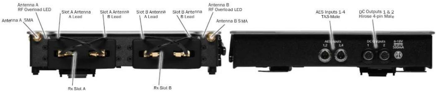
ANTENNA A & B SMA CONNECTORS Connects antenna to the SL-2. Both SMA antenna connectors can provide 12 V bias power up to 500 mA via a menu option. RF frequency range covers 470 - 1525 MHz. RF Filtering is available in the menus.
RX SLOT A & B Accepts Slot-in Unislot or SuperSlot receivers. Connects via DB-25 connector. SL-2 automatically locks the receiver in place. No screws are necessary to secure the receiver in the SL-2 slots. Cover empty slots with the included Rubber Slot Protector when not in use.
SLOT A & B ANTENNA A LEAD Distributes Antenna A to the left SMA connector of your receiver.
SLOT A & B ANTENNA B LEAD Distributes Antenna B to the right SMA connector of your receiver.
LEFT
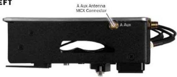
A & B AUX ANTENNA MCX CONNECTORS Distributes Antenna A and B to external receivers.
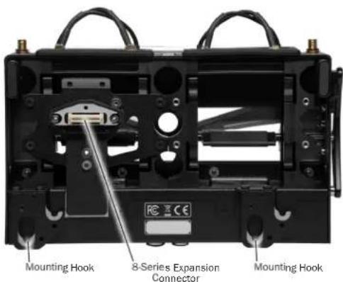
BOTTOM
SL-2 User Guide
AES INPUTS 1 - 4 Accepts up to four AES3 signals via the TA3-M input connectors. Each connector accepts two channels of AES3. Incoming signal can be routed to 8-Series Mixer-Recorder channels via the menus. Input type: AES3, balanced, TA3F connectors, Impedance: 110 ohms, Sensitivity: 200 mV or higher accepted Wiring: pin 1 = ground; pin 2 = +; pin 3 = -.
DC OUTPUTS 1 & 2 Each Hirose 4-pin male connector provides 6-18 V DC at 500 mA [pin-4=+, pin-1=-]. Useful for providing power to other peripherals such as RF equipment. Power can be defeated in the menus.
ANTENNA A & B RF OVERLOAD LEDS Each antenna input on the front panel of the SL-2 has an associated LED that displays incoming RF level status.
Red = approaching RF overload threshold of the SL-2 Orange = approaching overload threshold of digital wireless systems Off = no overload
To disable the LEDs go to SL-2 Options>Antenna LEDs and set to Off.
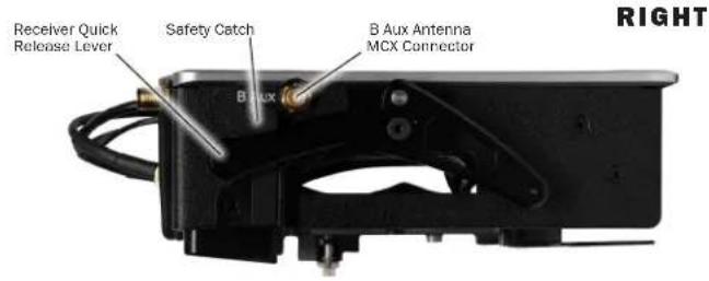
RECEIVER QUICK RELEASE LEVER & SAFETY CATCH To eject slotted in receivers, press in on the Safety Catch with one finger then push the lever down. Continue holding the lever down, then pull the receivers out of the slot with your other hand.
8-SERIES EXPANSION CONNECTOR Proprietary connector for attaching the SL-2 to the 8-Series. Provides all power, data, and audio signal needed for SL-2 and 8-Series functionality.
MOUNTING HOOKS These hooks are used to attach your 8-Series Mixer-Recorder. See Attaching the SL-2 for more details.
Attaching the SL-2
Power down the mixer-recorder and remove all power sources. Proper and complete assembly of the SL-2 is required for optimal RF emission performance. After removing the SL-2, it is important that you replace all original screws on the 8-Series mixer-recorder. See assembly instructions for the 8-Series model for which you will be attaching the SL-2.
833 & 888
The following instructions describe attaching the SL-2 to the 833 and 888. For this assembly you will need:
• 833 or 888 Mixer-Recorder (not included)
- SL-2
• 2x Rear Keyhole Pegs
• 2 mm Allen Wrench Hex 2-1/16"L
• #4 Phillips Screwdriver (not included)
STEP 1 Remove the magnetic expansion port cover on the top of the 833/888 by prying up gently to break the magnetic connection. Attach the connector cover to the bottom of the 833/888 for safekeeping.

natural_image
Hand placing a black electronic device labeled 'EEB' into a white electronic device (no visible text or symbols on the device itself)STEP 2 Using a #4 Phillips Screwdriver, remove the two black phillips screws from the Scorpio top panel as shown in the image below. Keep these screws in a safe place as they need to be re-installed if the SL-2 is removed from the 833/888.
natural_image
Person using a handheld device to adjust a black and white EEB (no visible text or symbols)STEP 3 Using the provided 2 mm Allen Wrench, screw in two Rear Keyhole Pegs into the threads where you removed the screws in Step 2.
natural_image
Close-up of a hand placing a black and white electronic device labeled 'EEB' on a white surface, with another device partially visible in the background (no readable text or symbols)STEP 4 Align the SL-2's bottom panel hooks with the Rear Keyhole Pegs on the 833/888. The SL-2 should be tilted with the front panel slightly higher than the rear. Take care not to bump the SL-2 expansion connector against the 833/888 top panel. Once the SL-2's Bottom Panel hooks and Rear Keyhole Peg's machined grooves are aligned, slide the SL-2 towards the front panel.
On an 833, the back of the silver mount screws will rest against this indent.
natural_image
Close-up of hands assembling a robotic device with visible wiring and a red circular mark on the mechanical component (no text or symbols)On an 888, the silver mount screws will fit inside this hole.
natural_image
Person installing or adjusting a device component with a red circular mark on the cover (no visible text or symbols)STEP 5 Make sure that the SL-2 Expansion Connector mates with the 833/888 Expansion Port. Then gently press down on the SL-2 to fully seat the pins of the connector.

natural_image
Person assembling a robotic device with visible EBB and 2.76 markings (no readable text or symbols)STEP 6 Using the supplied 2 mm Allen Wrench, secure the SL-2 to the 833/888 top panel with the two captive screws as shown in the image below.
natural_image
Close-up of a robotic device with a hand adjusting its internal components, showing no visible text or symbols.
natural_image
Hand placing a device into a black electronic device with visible E3E branding (no text or symbols on the device itself)SCORPIO
The following instructions describe attaching the SL-2 to the Scorpio. For this assembly you will need:
• Scorpio Mixer-Recorder (not included)
• SL-2
• 2x Rear Keyhole Pegs
- 6x Screw 6 mm STEEL M3 low-profile
- Scorpio Front Bracket
• SL-2 Rear Bracket
• 2 mm Allen Wrench Hex 2-1/16"L
• #4 Phillips Screwdriver (not included)
STEP 1 Remove the magnetic expansion port cover on the top of the Scorpio by prying up gently to break the magnetic connection. Attach the connector cover to the bottom of the Scorpio for safekeeping.
natural_image
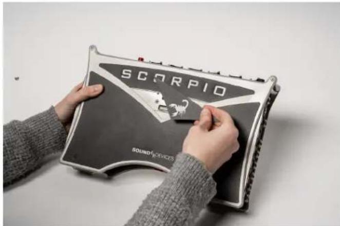
Person holding a device labeled 'SCORPIO' with a sound device logo, no visible text or symbols on the device itself.STEP 2 Using a #4 Phillips Screwdriver, remove the black phillips screw from the Scorpio top panel as shown in the image below. Keep these screws in a safe place as they need to be re-installed if the SL-2 is removed from the Scorpio.
STEP 3 Using the provided 2 mm Allen Wrench, screw in two Rear Keyhole Pegs into the threads where you removed the screws in Step 2.

natural_image
Close-up of a black and silver electronic device with a metallic grille and a 'Soundidge' logo on the cover (no readable text beyond branding)STEP 4 Position the Scorpio Front Bracket on the top panel of the Scorpio as shown in the image below. Secure the Scorpio Front Bracket with two 6 mm screws using the supplied 2 mm Allen Wrench.
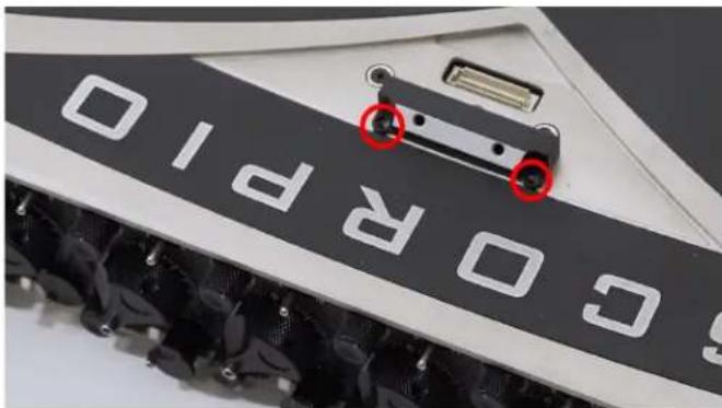
STEP 5 Position the SL-2 Rear Bracket on the rear panel of the SL-2 as shown in the image below. Secure the SL-2 Rear Bracket with two 6 mm screws using the supplied 2 mm Allen Wrench.
natural_image
Person assembling a black electronic device casing with visible wiring and components (no text or symbols)STEP 6 Align the SL-2 Rear Bracket and the Rear Keyhole Peg on the Scorpio. The SL-2 should be tilted with the front panel slightly higher than the rear. Take care not to bump the SL-2 Expansion Connector against the Scorpio top panel. Lower the rear of the SL-2 Rear Bracket onto the Rear Keyhole Peg on the Scorpio. Once the SL-2 Rear Bracket and Rear Keyhole Peg's machined grooves are aligned, slide the SL-2 towards the front panel.
natural_image
Close-up of a computer RAM module with a hand adjusting its cable (no visible text or symbols)STEP 7 Make sure that the SL-2 Expansion Connector mates with the Scorpio Expansion Port. Then gently press down on the SL-2 to fully seat the pins of the connector.
STEP 8 Secure the SL-2 to the Scorpio Front Bracket with two 6 mm screws using the supplied 2 mm Allen Wrench.
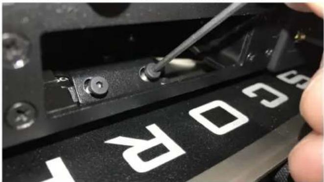
natural_image
Close-up of a hand using a screwdriver to adjust a black electronic device with white 'SC03' branding (no readable text beyond label)Removing the SL-2
Power down the mixer-recorder and remove all power sources. Proper and complete disassembly of the SL-2 is required for optimal performance. After removing the SL-2, it is important that you replace all original screws on the 8-Series mixer-recorder.
833 & 888
The following instructions describe removing the SL-2 from the 833 and 888. For this assembly you will need:
• 833 or 888 Mixer-Recorder (not included)
• SL-2
• 2x Rear Keyhole Pegs
• 2 mm Allen Wrench Hex 2-1/16"L
• #4 Phillips Screwdriver (not included)
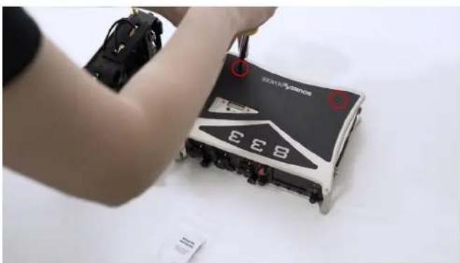
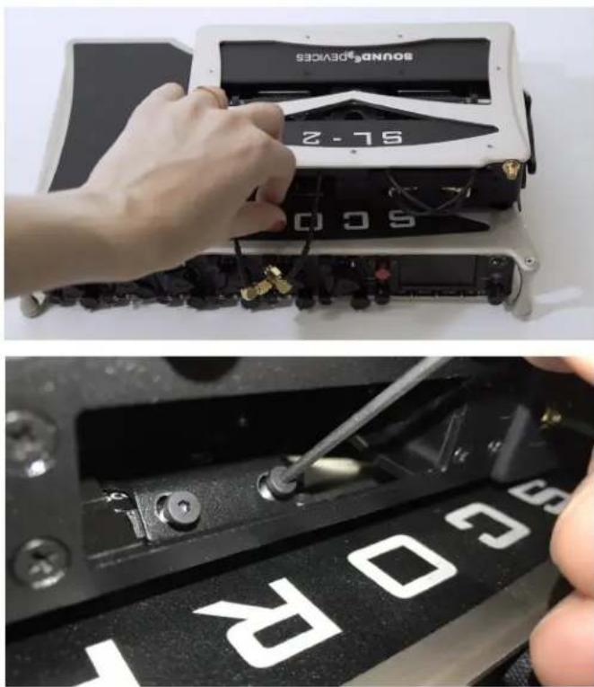
STEP 1 Remove any receivers, antennas and cables connected to the SL-2. Locate the two holes shown in the photo above.
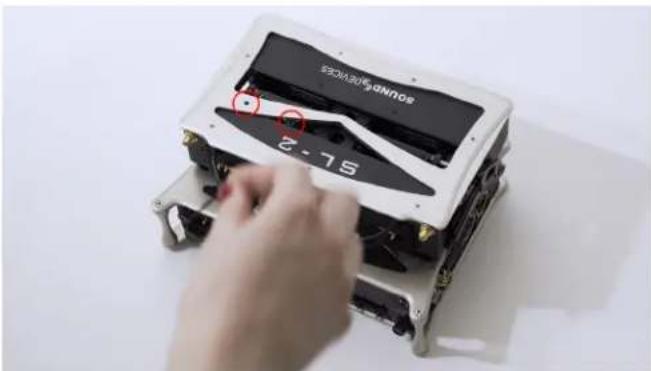
STEP 2 Insert the allen wrench into these holes, visually confirming that the wrench is in contact with the safety screws inside the SL-2. Turn the wrench counterclockwise to loosen the screws. Remove the screws and set aside.

natural_image
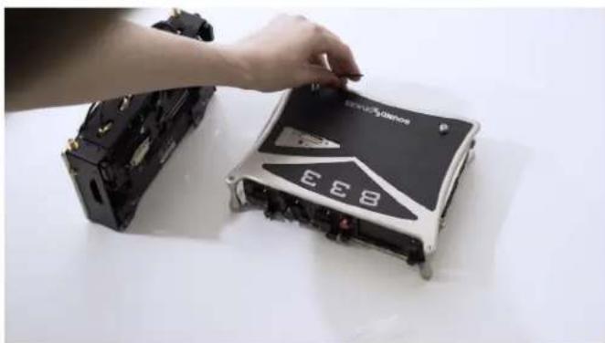
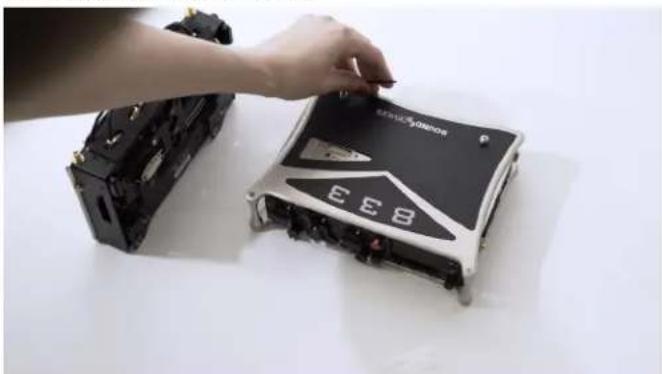
Hand placing a device into a black-and-white electronic device labeled '2-75' (no readable text or symbols beyond branding)STEP 3 Gently raise the SL-2 and slide slightly forward to disconnect from the mixer-recorder.

natural_image
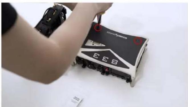
Person assembling a device with visible internal components and numbers (no readable text or symbols)STEP 4 Remove the two silver mount screws using the provided allen wrench.
natural_image
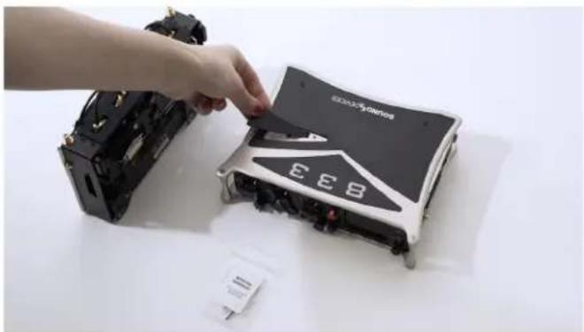
Close-up of a hand placing a black electronic device labeled 'EEB' into a white case, with another device partially visible (no readable text or symbols)STEP 5 Replace the originally provided rear black screws near the Sound Devices logo using #4 Phillips head screwdriver.
natural_image
Person assembling a small EEB device with a tool, no visible text or symbols on the device itselfSTEP 6 Replace the top plate.
natural_image
Hand placing a component labeled 'EEB' into a damaged electronic device (no readable text or symbols beyond branding)SCORPIO
The following instructions describe removing the SL-2 from the Scorpio. For this assembly you will need:
• Scorpio Mixer-Recorder (not included)
• SL-2
• 2x Rear Keyhole Pegs
- 6x Screw 6 mm STEEL M3 low-profile
- Scorpio Front Bracket
- SL-2 Rear Bracket
• 2 mm Allen Wrench Hex 2-1/16"L
• #4 Phillips Screwdriver (not included)
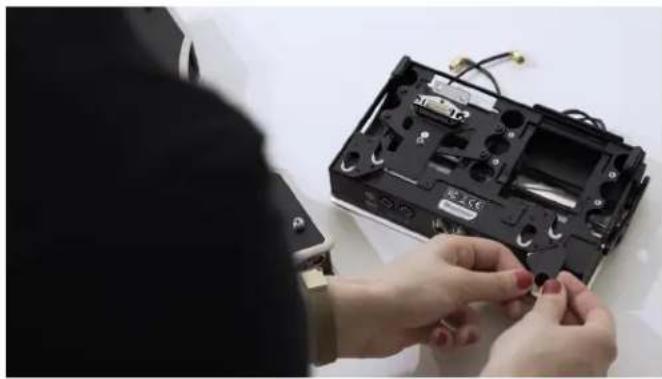
STEP 1 Remove any receivers, antennas and cables connected to the SL-2. Remove the two small black screws securing the SL-2 to the safety mount.
natural_image
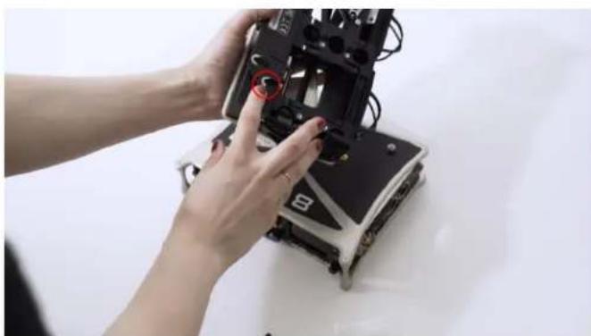
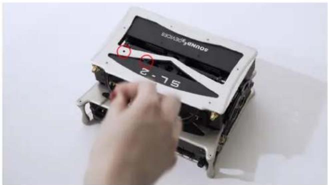
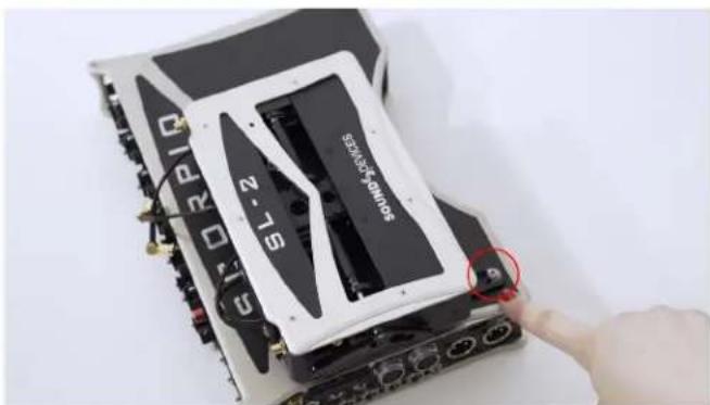
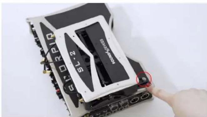
Two-panel image showing a hand adjusting a soundproof device with a tool, and a close-up of a black electronic device labeled '60R' (no readable text or symbols beyond labels)STEP 2 Gently raise the SL-2 and slide towards the rear of the unit. Lift up and over the silver mounting screw circled in red.
natural_image
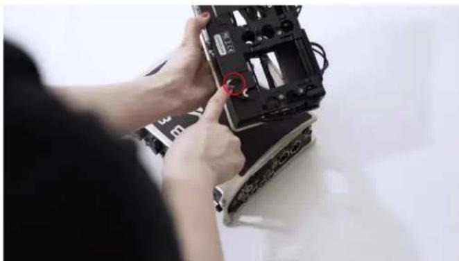
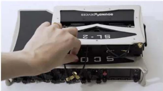
Close-up of a computer motherboard with a hand pointing to a component labeled 'SL-2' and 'COMPOSEROS', showing ports and wiring (no readable text beyond labels)STEP 3 Remove the two small black screws.
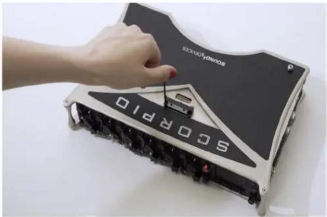
natural_image
Hand placing a component into a SoCOPRO10 electronic device (no visible text or symbols on the device itself)STEP 4 Remove the safety mount from the top panel of Scorpio.

natural_image
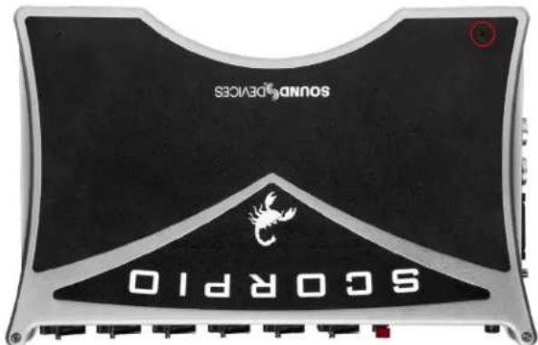
Top-down view of a black and silver electronic device labeled 'SCORPIO' with a red car on top (no readable text beyond branding)STEP 5 If desired, remove the additional Scorpio mounting hardware from the SL-2.
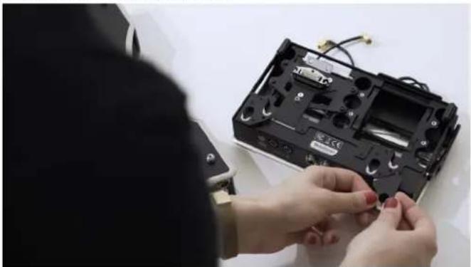
natural_image
Person assembling a black electronic device with visible wiring and components (no text or symbols)STEP 6 Perform steps 4-6 of 833/888 disassembly on Scorpio.
Inserting Receivers in the SL-2
It is important to turn off power to the SL-2 slot prior to removing and inserting receivers to avoid potential hardware damage. Slot power can be turned off in the Menu>System>Expansion Port menu, Menu>SuperSlot>Options>Slot Power, or by turning the 8-Series Mixer-Recorder Off.
STEP 1 Remove the Uni Slot adapter plate from your receiver. This part can be called different things depending on the manufacturer of your wireless receiver. Wisycom refers to this part as a Flange and Lectrosonics refers to it as blue bezel. The SL-2 was designed with a locking mechanism that negates the use of a plate. This also reduces overall weight and allows for quick installation or removal of receivers.
STEP 2 Remove the Rubber Slot Protector from the SL-2 slot and keep it in a safe place for future use. Reinsert the Rubber Slot Protector when removing the receiver.
STEP 3 Insert the receiver with the DSub connector down to mate with the SL-2 DSub connector.
STEP 4 Press in on the Saftey Catch and push the Receiver Quick Release Lever down. Continue to hold down the lever while firmly pushing the Rx into the slot. Then release the lever.
Removing Receivers from the SL-2
Press in on the SL-2 Safety Catch and push the Receiver Quick Release Lever down. Continue to hold down the lever while sliding the receiver out of the slot. Release the lever. Replace the Rubber Slot Protector to prevent against dust and debris.
Specifications
Specifications are subject to change without prior notice.
For the latest information available on all Sound Devices products, visit our website: www.sounddevices.com.
POWERING
All power supplied by host 8-Series machine
SL-2 idle power draw 1.3 W (without receivers or antenna)
ANTENNA IMPEDANCE
50 ohms
ANTENNA POWERING
12 V at 200 mA, menu selectable on/off
Serial remote control, Wisycom-compatible for ADFA and LFA powered antenna etc.
ANTENNA PRE-SELECT FILTERS
Menu selectable:
Wideband/bypass (low pass filter, 1.7 GHz upper cut-off)
470-614 MHz
542-694 MHz
606-770 MHz
770-960 MHz
1240-1525 MHz
INPUT RF ATTENUATORS
0 to -18 dB, in 6 dB steps, menu selectable
RF OUTPUTS
Auxiliary Antenna Outputs for additional receiver
DC OUTPUTS 1-2
500 mA max (each), 6-18 VDC passed through from host 8-series machine, depending on power source.
Hirose 4-pin connector: pin 4 = +, pin 1 = ground.
AES INPUTS
Two pairs for a total of four channels, AES-3 balanced, 110 ohms, TA-3 connectors
DIMENSIONS
H×W×D
4.5 cm × 21.3 cm × 13.1 cm;
(1.8 in x 8.4 in 5.1 in)
WEIGHT
1.35 lbs (unpackaged)
0.61 kg (unpackaged)
Declaration of Conformity
Manufacturer's Name: Sound Devices, LLC
Manufacturer's Address: E7556 State Road 23 and 33
Reedsburg, WI 53959 USA

Declares under sole responsibility that the product as delivered
Product Name: SL-2
Model Number: SL-2
Description: Dual SuperSlot Wireless Module
Product Options: This declaration covers all options of the above product.
Is in conformity with the essential requirements of the following relevant Union harmonisation legislation:
Radio Equipment Directive (RED) 2014/53/EU
Low Voltage Directive 2014/35/EU
RoHS Directive 2011/65/EU
The following harmonized standards and/or normative documents were applied:
Safety EN 62368-1:2014
EMC
This Declaration of Conformity applies to the above-listed product(s) placed on the EU market after:
June 29, 2020
Date

Matt Anderson - Sound Devices, LLC President
SOUND DEVICES
Post Office Box 576
E7556 State Rd. 23 and 33
Reedsburg, Wisconsin 53959 USA
support@sounddevices.com
+1 608.524.0625 main
+1 608.524.0655 fax
800.505.0625 toll free
www.sounddevices.com