
RMZ-955 - Controller ROTEL - Free user manual and instructions
Find the device manual for free RMZ-955 ROTEL in PDF.


| Product Type | Multi-Room Controller/Amplifier |
| Number of Zones | 4 (expandable to 16 with multiple units) |
| Power Output | Not specified; internal amplifiers for each zone (4 ohms minimum) |
| Inputs | 4 RCA line-level inputs (Tuner, CD, Tape/Sat, Video/LD) |
| Outputs | 4 preamp outputs (variable/fixed), 4 speaker outputs (screw terminals) |
| Loop-Through Outputs | 4 RCA outputs for cascading multiple RMZ-955 units |
| IR Control | Front panel IR flood emitter, 4 rear panel IR repeater jacks (3.5mm) |
| Remote Control | RR-952 hand-held remote with RSM-901 sensor/display or RKP-901 keypad |
| Data Connections | 6-pin Methode connectors (Belden 9536 cable recommended) |
| AC Power | 120V/60Hz (USA model); 2 convenience outlets (1 switched, 1 unswitched, 100W each) |
| AC Link | 3.5mm stereo mini-jack for multi-controller systems |
| Paging | RCA trigger and audio input/output for announcements |
| Dimensions (Approx.) | 17 in (432 mm) wide, 4 in (102 mm) high, 14 in (356 mm) deep |
| Weight (Approx.) | 15 lbs (6.8 kg) |
| Special Features | Alarm clock, source labeling, power toggle, system standby, RC-5 output |
| Compatible Source Components | Rotel, Sony, Pioneer, Yamaha, Denon, Panasonic, Toshiba, RCA, etc. |
| Cleaning | Dry cloth or vacuum cleaner; do not use liquids |
| Safety | Do not expose to moisture; unplug if liquid enters; refer servicing to qualified personnel |
| Warranty | Refer to Rotel warranty card or contact Rotel of America |
Frequently Asked Questions - RMZ-955 ROTEL
User questions about RMZ-955 ROTEL
0 question about this device. Answer the ones you know or ask your own.
Ask a new question about this device
Download the instructions for your Controller in PDF format for free! Find your manual RMZ-955 - ROTEL and take your electronic device back in hand. On this page are published all the documents necessary for the use of your device. RMZ-955 by ROTEL.
USER MANUAL RMZ-955 ROTEL
Installation & Operation Manual
Operating
Instructions
begin on Page 23
CAUTION
RISK OF ELECTRIC SHOCK DO NOT OPEN

CAUTION: TO REDUCE THE RISK OF ELECTRIC SHOCK, DO NOT REMOVE COVER. NO USER-SERVICEABLE PARTS INSIDE. REFER SERVICING TO QUALIFIED SERVICE PERSONNEL.
APPLICABLE FOR USA, CANADA OR WHERE APPROVED FOR THE USAGE
CAUTION: TO PREVENT ELECTRIC SHOCK, MATCH WIDE BLADE OF PLUG TO WIDE SLOT. INSERT FULLY.
ATTENTION: POUR EVITER LES CHOCS ELECTRIQUES, INTRODUIRE LA LAME LA PLUS LARGE DE LA FICHE DANS LA BORNE CORRESPONDANTE DE LA PRISE ET POUSSER JUSQU AU FOND.
This symbol is to alert the user to the presence of uninsulated dangerous voltages inside the product's enclosure that may constitute a risk of electric shock.

This symbol is to alert the user to important operating and maintenance (service) instructions in this manual and literature accompanying the product.
WARNING:
There are no user serviceable parts inside. Refer all servicing to qualified service personnel.
WARNING:
To reduce the risk of fire or electric shock, do not expose the RMZ-955 to moisture or water. Do not allow foreign objects to get into the enclosure. If the unit is exposed to moisture, or a foreign object gets into the enclosure, immediately disconnect the power cord from the wall. Take the unit to a qualified service person for inspection and necessary repairs.
Read all the instructions before connecting or operating the RMZ-955. Keep this manual so you can refer to these safety instructions.
Heed all warnings and safety information in these instructions and on the product itself. Follow all operating instructions.
Clean the RMZ-955 only with a dry cloth or a vacuum cleaner.
Keep the ventilation inlets on the unit unobstructed. For example, do not place the unit on a bed, sofa, rug, or similar surface that could block the ventilation slots. If the RMZ-955 is placed in a bookcase or cabinet, there must be sufficient clearance around the unit and ventilation of the cabinet to allow proper cooling.
Keep the RMZ-955 away from radiators, heat registers, stoves, or any other appliance that produces heat.
The RMZ-955 must be connected to a power supply only of the type and voltage specified on the rear panel of the unit.
Connect the RMZ-955 to the power outlet only with the supplied 3-pin polarized grounded power supply cable or an exact equivalent. Do not modify the supplied cable in any way. Do not attempt to defeat grounding and/or polarization provisions. The cable should be connected to a 3-pin polarized grounded wall outlet, matching the wide blade of the plug to the wide slot of the receptacle. Do not use extension cords.
Do not route the power cord where it will be crushed, pinched, bent at severe angles, exposed to heat, or damaged in any way. Pay particular attention to the power cord at the plug and where it exits the back of the unit.
The power cord should be unplugged from the wall outlet if the unit is to be left unused for a long period of time.
Immediately stop using the RMZ-955 and have it inspected and/or serviced by a qualified service agency if:
• The power supply cord or plug has been damaged.
- Objects have fallen into or liquid has been spilled into the unit.
• The unit has been exposed to rain.
• The unit shows signs of improper operation
• The unit has been dropped or damaged in any way
Place the RMZ-955 on a fixed, level surface strong enough to support its weight. Do not place the RMZ-955 on a moveable cart that could tip over.

natural_image
Silhouette of a person pushing a large cart with a flag, enclosed in a circular frame (no text or symbols)

Getting Started 4
Controlling the Remote Zones 4
System Flexibility 4
System Highlights 4
Component Description 4
RMZ-955 Controller/Amplifier 4
System Planning 4
RR-952 IR Remote Control 5
RSM-901 Sensor/Display 5
RKP-901 Keypad 5
RSM-901/RKP-901 Combination 5
Placement 6
Connections: 6
IR Flood Emitter 6
IR Repeater Jacks 6
System Wiring Considerations 6
Data Cable and Connectors 6
Speaker Cables 7
Zone Configuration 7
Basic Zone Complement 7
Loudspeakers 7
Installation: RMZ-955 Controller 8
AC Line Connections 8
AC for the RMZ-955 8
AC for Source Components 8
Rotel RLC-900 AC line conditioner/switcher 8
Special AC features 8
Source connections 9
Source inputs 9
Source outputs 9
Speaker Connections 10
Preamp outputs 11
Variable vs. Fixed Level 11
Data cable connections 12
Infrared Control System 13
Front Panel IR Flood Emitter 13
Rear Panel IR Repeaters 13
Paging Input 14
Paging Inhibit 14
Installation: Zone Control Devices 15
RSM-901 Sensor/Display 15
RSM-901 Mounting 15
RSM-901 Data Connections 16
Battery Enable 16
Zone Configuration 16
Source Component Labels 16
Master/Slave Configuration 16
System Reset 17
Source Component Set-up 17
RKP-901 Keypad 17
RKP-901 Mounting 17
RKP-901 Data Connections 17
Zone Connection Strategies 18
Installation: Multi-controller Systems 18
AC Power 20
AC Connections 20
AC Link 20
Manual AC Override 20
Source Connections 20
IR Connections 21
For 2 RMZ-955s (5 to 8 zones): 21
For 3 RMZ-955s (9-12 zones): 21
For 4 RMZ-955s (13-16 zones): 22
Exception: Multiple IR Flood Emitters 22
Paging Connections 22
Notes on multi-controller set-up 23
Power Toggle Set-up 23
Source Component Set-up 23
"Engaged" Indicator 23
System Set-up & Programming 24
Source Commands 24
Source Command Set-up 24
Power Toggle 25
Operating Instructions 26
RR-952 Hand-held Remote 26
Input Selector Buttons 26
Tuner control buttons 26
CD control buttons 27
Tape/Satellite TV control buttons 27
Video/LD control buttons 27
Mute 27
VOLUME UP/VOLUME DOWN 27
STBY 27
“X” 27
RKP-901 Keypad 28
Input Select commands 28
System commands 28
Source Control Commands 28
RSM-901 Sensor/Display 29
Controls and Displays 29
Dot Matrix Display 29
Setting Alarm, Time, and Custom Functions 30
For Assistance 31
Getting Started
The Rotel RMZ-955 Multi-Room Control System distributes audio signals from a single set of source components to as many as four separately controlled remote zones or listening areas. The centrally located RMZ-955 controller/amplifier contains source selection, microprocessor controlled communications circuitry and independent preamplifier/power amplifiers for all zones.
Controlling the Remote Zones
Users can select either of two ways to control remote zone operation. The first is the RR-952 hand held remote. This generates infrared (IR) control pulses read by the wall-mounted RSM-901 sensor/display. The RSM-901 sensor/display then transmits commands to the RMZ-955 through hard-wired connections.
The second method uses the wall-mounted RKP-901 keypad to transmit commands directly to the RMZ-955. The RKP-901 is also hard-wired to the RMZ-955 controller/amplifier.
Users can select a combination of sensor and keypad operation for any zone. The system accepts inputs from up to three sensor/displays and three keypads (for a total of six input devices) per zone.
System Flexibility
The Rotel RMZ-955 Multi-Room Control System is exceptionally flexible. In addition to the RMZ-955 controller/amplifier, a simple two zone system might include just one RR-952 hand held controller/RSM-901 IR sensor/display combination for one zone and one RKP-901 keypad in the second.
In a more elaborate configuration, a single RMZ-955 accepts commands from four separate zones via twelve IR sensor/displays and twelve keypads.
Up to four RMZ-955 controllers can be linked together for a system with as many as sixteen independent zones.
System Highlights
- Keypad or handheld remote operation of source components. No programming required – built-in codes for Rotel and other popular components.
- Single button operation for source selection and "play".
• Full user control, including system standby from any zone.
• Built-in Paging input with muting in selected zones. - Near-universal Infra-red repeating system. Remote control available even when a zone is not active.
- Alarm clock function with independent wake-up in each zone.
Component Description
RMZ-955 Controller/Amplifier

The RMZ-955 Controller/Amplifier is the heart of the RMZ-955 Multi-Room Control System, featuring:
- Four separate microprocessor-controlled stereo preamplifier/power amplifier sections, one for each remote zone
• RCA inputs for up to four sources - "Loop through" RCA outputs which allow multiple RMZ-955 controllers to be linked together for large systems up to 16 zones.
- RCA line level preamp outputs for use with external amplifier systems. These outputs can be internally configured to provide a variable level signal or a fixed level signal.
- Screw-type quick connect speaker outputs
- Control data input for each zone is via industry-standard 6 pin Methode connectors
- 3.5 mm stereo jack "AC Link" connections for full system control from any zone in large, multi-controller systems
- RCA output jack for RC-5 remote control protocol components
- High power front panel IR flood emitter to transmit remote zone commands to associated source components
- Four mini-plug IR repeater outputs
- Two polarized AC convenience outlets with 100 watts capacity each: one switched to allow easy remote control of total system power if desired, the other unswitched
- Front panel LED indicators for Power On/Off, zone status, command pulse processing
System Planning
The RMZ-955 is designed to be used as a stand-alone control center for a multi-zone distribution system using dedicated source components. It features loop-through source connec-
RR-952 IR Remote Control

natural_image
Black remote control device with keypad and buttons (no visible text or symbols)The RR-952 infrared remote control serves a dual purpose. In addition to providing dedicated pushbuttons for the most needed functions of both the RMZ-955 controller/amplifier and source components, it also serves as a quick set-up tool during initial configuration.
The RR-952 has a special high intensity IR transmitter. In conjunction with the system's sensitive receiver modules, this transmitter assures reliable operation under a wide variety of conditions.
RSM-901 Sensor/Display

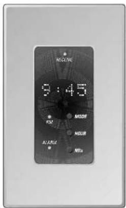
The wall-mounted RSM-901 Sensor/Display receives commands from the RR-952 hand held remote and, after processing to ensure maximum data integrity, sends these codes to the RMZ-955 controller/amplifier.
In addition, the RSM-901 provides continuous system status information (source, time, volume setting, etc.) at each remote location with a dot matrix display. Also available is a programmable alarm function.
You'll find details of the display in the Set Up and Operation sections of this manual.
NOTE: An RSM-901 connected to the Zone A data input MUST be used during initial set-up.
RKP-901 Keypad

The RKP-901 is a wall-mounted keypad for convenient remote operation of the entire system. The keypad can be used as a stand-alone control device, although it is most functional when installed with the RSM-901 sensor-display. Its 12 key design is the optimum balance between flexibility and simplicity, providing single-key control of the system and source components (selecting and starting a CD player, for example). In addition, the RKP-901 allows total system shut-down from a remote location. It mounts conveniently in a standard single width wall box or in a dual width box with a RSM-901 sensor/display. (see page 25)
RSM-901/RKP-901 Combination
Mounting both the sensor/display and keypad in one double-width wall box carries several advantages. It simplifies the installation. It also focuses the user on one location in each zone, i.e. walk to the keypad or aim the hand held remote control at the same wall-plate.

tions which allow linking additional RMZ-955 controllers for large systems. Depending on the design of the associated components, these pass-through source connections may alternatively be used to "share" source components with a separate home theater or audio system.
Placement
Place the RMZ-955 on a stable surface in an equipment rack or cabinet. Note that the RMZ-955 is slightly deeper than most source components (tuners, CD players, cassette decks, etc.) and should not generally be placed on top of these units.
Connections:
Make sure that you have enough room to run all the connecting cables and dress them appropriately behind the RMZ-955. Although we'll explain each connection fully in following sections of this manual, glance through the following list of possible connections and decide how much space you'll need.
a) Four pair of RCA interconnects - one pair from each source.
b) Eight heavy gauge speaker cables (two for each zone).
c) Four six-conductor + shield data cables, each terminated with the proper IDC strip connector.
d) One shielded RCA to RCA interconnect for RC-5 remote control code connection.
e) One pair of RCA to RCA interconnects to power amplifiers from each corresponding zone's "Pre-out" terminals.
f) Up to four mini-plug (3.5 mm) cables from the RMZ-955's "Infra Red" outputs to remote IR transmitters.
g) Four more pair of RCA to RCA interconnect cables – one each to the appropriate input of the next RMZ-955 in large multi-controller systems.
h) Additional loudspeaker connections as required for systems using more than one RMZ-955 controller/amplifier.
i) 3.5 mm to 3.5 mm cable for AC "link" connections as required for systems using more than one RMZ-955 controller/amplifier.
j) Up to six "TX-FORM" terminal block jumper wires needed when cascading multiple RMZ-955 controller/amplifiers.
We STRONGLY RECOMMEND that you attach a tag or strip to each cable and wire to identify it (e.g. "To Input 3 from tape deck."). This will help in troubleshooting as well as make future service calls or system add-ons much less frustrating.
IR Flood Emitter
The RMZ-955 has a high intensity front panel IR flood emitter designed to transmit commands from the remote zones to the appropriate source component. Although exact performance will vary, this high power transmitter has an effective operating range of approximately 40' under normal conditions.
If the RMZ-955 is on an open shelf, the emitter's signal must first travel to an IR-reflective surface (an opposing wall, for example) and then to the source component.

Keep total IR signal travel to 40' or less. Remember that it must travel to a hard reflective surface and back again.
Note: If an RSM-901 sensor display is located in the same room as the RMZ-955 controller, it is essential that the output form the front-panel IR flood emitter NOT reach the RSM-901 sensor. IR loop problems can cause intermittent operation.
IR Repeater Jacks
The RMZ-955 also has four rear panel IR output jacks for use with industry standard IR repeaters (made by Xantech and others). The use of these external repeaters on each source component is ideal in situations where output from the front panel flood IR emitter is blocked from the source components by a door, full depth shelf, etc. It is also an ideal solution when the front panel flood emitter output could reach an RSM-901. When IR repeaters are used, the front-panel flood emitter can be easily disabled.
System Wiring Considerations
Data Cable and Connectors
The data path between the RMZ-955 controller/amplifier and RSM-901 sensor/displays and RKP-901 keypads must be made with cable with six insulated conductors plus a foil and/or braided outer shield. We recommend a Belden 9536 equivalent for best results. The RMZ-955 system data connectors work only with cables using 24 gauge conductors. Make sure that all data cables conform to this requirement.
Data cable termination is via industry-standard 6 pin IDC connectors made by Methode and others. (The Methode part number is 1300-106-424.) Data cable connection instructions are found in the Installation section of this manual (see page 9).
Speaker Cables
Unshielded two conductor 18 gauge (AWG) speaker wire is the minimum acceptable standard for connections between the RMZ-955 controller/amplifier and zone loudspeakers. Particularly long runs may call for use of heavier wire.
Zone Configuration
Basic Zone Complement
Each remote zone must include at least one control device and a pair of loudspeakers. The control device may be a RR-952 hand held remote and an RSM-901 sensor/display combination. Or it can be a RKP-901 keypad, either stand-alone or with a RSM-901.
Remember that the RSM-901 sensor/display also provides useful visual clues to total system operation and additional convenience features. Most zones will use multiple control devices, with the combination of one RSM-901 sensor/display, one RKP-901 keypad, and one RR-952 being the most common.
The RSM-901 sensor/display reads infrared signals generated by the RR-952 hand held remote and, after translating them into a digital code that is highly resistant to interference, sends them to the RMZ-955 controller/amplifier. The RKP-901 simply translates key pushes into digital code before sending them to the controller/amplifier.
Loudspeakers
These will vary with installation requirements and user expectations. The RMZ-955's amplifier sections are optimized for impedance loads of four ohms or higher.

flowchart
graph TD
    A["ATTEL MAINLINE CUSTOM OWNER/CELL"] --> B["AM/FM Tuner"]
    A --> C["CD Player"]
    A --> D["Tape Deck"]
    A --> E["LD/DVD Player"]
    A --> F["Living Room"]
    A --> G["Family Room"]
    A --> H["Bedroom"]
    A --> I["Kitchen"]
    A --> J["Other Devices"]
    style A fill:#f9f,stroke:#333
    style B fill:#ccf,stroke:#333
    style C fill:#ccf,stroke:#333
    style D fill:#ccf,stroke:#333
    style E fill:#ccf,stroke:#333
    style F fill:#cfc,stroke:#333
    style G fill:#cfc,stroke:#333
    style H fill:#cfc,stroke:#333
    style I fill:#cfc,stroke:#333
    style J fill:#cfc,stroke:#333
Installation: RMZ-955 Controller
This section covers all hardware installation and configuration issues related to the RMZ-955 controller, including wiring connections for AC power, source connections, speaker connections, pre-amp connections, data cable connections to the remote zones, Infrared control connections, and special features such as the paging feature. The next section of the manual (see page 12) covers similar topics related to the installation, wiring, and hardware configuration of the zone control devices – the RSM-901 Sensor/Display and the RKP-901 Keypad.
For the sake of simplicity, these two sections cover the installation of a basic 4-zone system with a single RMZ-955 controller, since this is the most typical system configuration. There is a separate section Installation: Multi-controller Systems (page 15) that covers installation, wiring, and configuration topics related to larger, more complex systems with multiple RMZ-955 controllers.
AC Line Connections
AC for the RMZ-955
Plug the RMZ-955 controller/amplifier into an unswitched AC source only, i.e. a wall outlet. It is essential for proper system operation that the RMZ-955 be plugged into a constant source of AC power, since it has "stand-by" circuitry that must receive power for full control from any zone at any time.
We recommend a powerline filter as the RMZ-955 contains a number of microprocessor ICs that may benefit from the extra protection afforded by a quality filter/surge protector.
AC for Source Components
The RMZ-955 has two rear panel AC convenience outlets, one switched and the other unswitched. These may be used to supply power for components used with the RMZ-955. Each outlet carries a maximum load rating of 100 watts.
Unswitched AC outlet: The RMZ-955's Unswitched AC outlet supplies AC current whenever the RMZ-955 is plugged into a live AC source. This outlet is NOT controlled by the setting of the RMZ-955's front panel power switch.
Switched AC outlet: This outlet provides a mechanism for controlling AC power to other components, such as source components. When the RMZ-955's front panel switch is Off, the switched AC outlet is also off. Even when the front panel switch is turned On (i.e., when the RMZ-955 first powers up to "Standby" mode), the switched outlet remains off until the RMZ-955 receives a zone activation command from one of the remote zones. The switched AC outlet then remains on until the front panel power switch is turned Off or the RMZ-955 receives a "system shutdown" command from a remote zone.
The switched outlet provides the mechanism for "powering up" or "powering down" all of the source components from the remote zones. We recommend plugging the AC power cords from the source components into the switched outlet on the back of the RMZ-955.
Rotel RLC-900 AC line conditioner/switcher
We strongly recommend the use of the RLC-900 AC line conditioner/switcher to improve both the performance and convenient operation of all system components. The RLC-900's benefits include increased protection from AC power line surges and improved system AC power management for proper turn-on and turn-off sequences.
To incorporate the RLC-900, follow these steps:
a) Plug all system source components into the RLC-900's "Digital Equipment" or "Accessories" outlets as appropriate.
b) Plug the RMZ-955's AC power cord into the RLC-900's "UNSWITCHED" outlet.
c) Plug the RLC-900's "Control Cord" into the RMZ-955's SWITCHED outlet.
d) Plug the RLC-900's "Main Power" cord into an unswitched AC outlet such as a wall receptacle, etc.
When a system activation command is sent from a remote zone, the RLC-900 turns on all source components automatically.
Special AC features
Some source components power up in a standby mode when AC power from a switched outlet turns them on. These components require a separate command to fully activate them. The RMZ-955 has a built-in software function, called "power toggle" that can handle this "power up" sequence, if necessary. This feature is fully described in the System Set-up & Programming section of this manual on page 22.
Source connections
The RMZ-955 has four pair of RCA inputs for four source components, as well as four pair of RCA "loop-through" outputs that can send the source signals to other components.
Source inputs
Connect LINE LEVEL sources (CD player, tuner, etc.) to the RMZ-955's rear panel inputs as follows.
Using shielded RCA-RCA cables, connect the source's output to the corresponding source input on the RMZ-955. Connect analog outputs from the source components as indicated to assure clear operation with both the RR-952 hand held remote and the RKP-901 keypad:
| Tuner | → | RMZ-955 Input 1 |
| CD player | → | RMZ-955 Input 2 |
| Tape deck / DSS Satellite | → | RMZ-955 Input 3 |
| CD2 / VCR / DVD / LD | → | RMZ-955 Input 4 |
Make sure to observe correct channel continuity from source to RMZ-955. The RMZ-955's RCA inputs are labelled for easy identification with Left Channel connections on the top row and Right Channel connections on the bottom row.
Note 1: The RMZ-955 does not accept a phono cartridge's output directly. If required, use a separate phono preamp (such as Rotel's RQ-970BX) to boost phono signal to line level.
Note 2: Use only FIXED LEVEL source outputs to the RMZ-955.
Source outputs
Each source input on the RMZ-955 has a matching pair of "loop-through" output RCA jacks. The primary use of these "loop-through" outputs is to pass the signal from each source component to additional RMZ-955 controllers in large multi-zone systems (see page 15 for details on installing large systems).
In some cases, these "loop-through" outputs may alternatively be used to "share" the source components with a separate home theater or audio system. If the source is shared by another system, connect each pair of RMZ-955 source outputs to the appropriate inputs of the main system's preamplifier as shown in the hook-up illustration.
Note: The source sharing does not work with all combinations of components. Specifically, home theater and audio systems with micro-processor controlled source input switching may result in problems such as interference or "mixing" between shared sources.

Tuner connected to Source 1 input (with optional pass-through to preamp for shared use with separate system).
Speaker Connections
The RMZ-955 is supplied with eight quick-connect screw terminal plugs for speaker connections – one twin-terminal plug is used for each speaker, two for each zone. Make the wire connections from a speaker to a quick-connect plug and then insert the plug into the appropriate receptacle on the back panel of the RMZ-955, as illustrated.
Strip back each speaker wire's insulation by 1/4 inch. Insert the bare wire into one "slot" on the quick-connect plug and secure by tightening the corresponding clamping screw. Repeat for the other conductor, making sure that there are no loose strands of wire which could cause a short. Repeat for the second speaker in zone one and then continue with the other zones.
Remember to observe proper polarity when connecting all loudspeakers. The amplifier's "+" output should connect to the proper speaker's "+" terminal. "Out of phase" loudspeaker hook-ups (where one speaker in a stereo pair is inadvertently connected "+" to "-" and vice versa) may not be immediately noticeable but will not be as pleasing as a properly connected stereo pair. BE CAREFUL AND BE PATIENT.
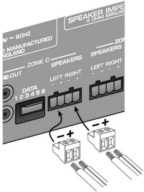

Speaker connections from Zone D of RMZ-955
Also showing Zone C preamp output connections for use with optional power amplifier
The long runs from amplifier to speaker typically found in multi-zone installations demand heavy gauge, low resistance speaker wire. Small diameter wire reduces effective amplifier power and adds substantial distortion to the audio signal. Avoid problems by following these minimum recommendations:
Under 150'
150' - 300'


18 gauge wire
16 gauge wire
Loudspeaker runs over 300' are discouraged.
Preamp outputs
Two RCA jacks (Left and Right Channel) labeled "Pre-out" provide line level outputs for each of the four zones. These are primarily used for systems with external power amplifiers driving speakers in one or all of the remote zones.
Each zone's preamp output is fully buffered and may be used either independently or along with the RMZ-955's internal amplifiers to provide additional flexibility for demanding installations.
If a zone requires additional amplification, use standard RCA-RCA shielded interconnects from these outputs to a separate power amplifier's unbalanced line inputs as shown in the hook-up illustration on the preceding page. Connect the left channel "Pre-out" jack to the left channel input on the power amplifier for that zone; then repeat for the right channel connections.
Variable vs. Fixed Level
As delivered, the preamp outputs are configured to provide a variable level output, i.e. the volume level of the signal can be adjusted with a volume control in each zone. Alternatively, the pre-amp outputs for one or more zones can be converted to provide a fixed level line drive signal, i.e. a signal that is always at a fixed gain (0.25dBV below that of the source component). This may be useful in certain custom applications.
Converting the pre-amp outputs to fixed level operation requires removing the top cover of the RMZ-955 and locating the four "line driver" plug-in modules. Looking from the front of the unit, these are small vertical circuit boards located in front of the heat sink. They are labeled Zone A through Zone D, from left to right.
Notice that the modules are printed circuit boards that plug into the main board. Each module has two rows of "pins", one on the bottom (which is plugged into a socket as delivered from the factory) and the other pointing up. To reconfigure from variable level pre-amp outputs to fixed level pre-amp outputs, simply remove the module from the socket on the main circuit board, rotate it 180 degrees, and reinsert it in the same socket using the row of pins on the opposite end.

flowchart
graph TD
    A["RMZ-955 Circuit Board"] --> B["Zone A ZONE B ZONE C ZONE D"]
    B --> C["Factory default: variable level pre-amp output"]
    C --> D["Output 1 LINE DRIVER 15"]
    C --> E["Output 2 LINE DRIVER 15"]
    D --> F["Forward to output"]
    E --> G["Forward to output"]
    style A fill:#f9f,stroke:#333
    style B fill:#ccf,stroke:#333
    style C fill:#cfc,stroke:#333
    style D fill:#fcc,stroke:#333
    style E fill:#cff,stroke:#333
    style F fill:#ffc,stroke:#333
    style G fill:#ffc,stroke:#333
Note that the side of the module with the actual electronic components remains facing to the left side of the RMZ-955, regardless of which set of header pins you use. Also note that the pins and the socket are labeled 1 — 15. Pin 1 is always inserted into Socket 1, etc.
Note You can configure each of the four zones independently, by rotating just its module. Some zones can be configured as variable outputs, while others are reconfigured as fixed outputs by reorienting some or all of the modules.
Data cable connections
Data communication to and from the RMZ-955 controller and the remote zones' RSM-901 sensor/displays and RKP-901 keypads is by 6 conductor shielded cable.
Note: One, and only one, data cable runs from the RMZ-955 to each zone. Multiple sensor/display and keypad combinations in one zone should be wired via series connections detailed in the section on Zone Connection Strategies (page 15).
We recommend the use of Belden 9536 cable or the equivalent. The Methode data connectors supplied with the RMZ-955 only accept cable with 24 gauge conductors.
Using cable with a foil and/or braided shield is absolutely essential in maintaining data integrity over the long runs between the controller/amplifier and a zone's control code generating devices. Make sure that the shield is firmly connected at both the RMZ-955 and at any command device terminal.
We recommend that you run each zone's data cable and speaker cables together to save time. There is absolutely no performance penalty for doing so.
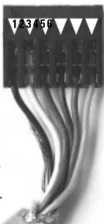
PROPER DATA CABLE TERMINATION IS CRITICAL. All connections for RMZ-955 and the remote zone's RSM-901 sensor/displays and RKP-901 keypads use the color code shown in the following illustration:
DATA CONNECTOR WIRING CODE
Pin 1· black & shield
Pin 2• white
Pin 3·red
Pin 4• brown
Pin 5· blue
Pin 6· green
Connections are made in the same order at both ends of the cables.
natural_image
Close-up of a black electronic component with multiple wires, no visible text or symbolsThe supplied Methode connectors need to be crimped to lock to the data cable's 24 gauge conductors.
Note: Do not use a screwdriver, metal ruler or knife blade to "crimp" these connections. You may think these tools will work but you will be mistaken. USE THE DEDICATED CRIMPING TOOL SPECIFICALLY DESIGNED FOR THESE CONNECTORS. This tool is available from Rotel.
- Strip about 1.5" of the outer cable insulation using a sharp knife. Separate the outer shield from the conductors and trim it off flush with the outer insulation, being careful not to trim off the shield or "drain" wire.
- DO NOT strip insulation off the six individual conductors as the connector automatically makes contact with the conductor core when crimped.
- Place the shield or "drain" wire into slot 1 of the connector. Then, place the BLACK conductor immediately on top of the drain wire in slot 1, hold them both in place and push the crimping tool handle until you hear a slight "click." Both conductors should now be locked into slot 1. The rachet action of the crimping tool ensures proper connection. The clicking sound tells you that the connector slot contacts have pierced the conductor's insulation.
- Continue the process following the color code guide above until all other conductors are locked in the appropriate connector slots. Remember that slot 1 is the ONLY ONE to get the drain wire and a conductor. All other slots receive only a conductor.
After attaching the cable conductors to the connector, insert it into the appropriate zone's 6 pin data terminal on the RMZ-955's rear panel. Be careful to center the connector over the terminal pins before inserting.
The maximum cable length for guaranteed operation is 300'. Longer lengths may be practical in some installations with low RF (radio frequency) and EMI (Electro-Magnetic Interference).
Infrared Control System
The RMZ-955's IR system provides extensive control flexibility accepting remote control codes generated by keypads and/or hand-held remotes, relaying them to the system controller, and passing them along to the source components via a front-panel flood emitter or individual remote IR emitters plugged into the rear panel. However, please note the following points:
The IR codes generated by the RR-952 hand held remote are RMZ-955 "system specific" codes and ARE NOT the same codes generated by a source component's own controller, even for functions that appear identical such as "CD play," for example. In other words, you can not use the RR-952 to directly control a Rotel CD player but must use it through an RSM-901 sensor/display from a remote zone.
The RMZ-955 IR control system does the following:
- An RSM-901 sensor/display receives the remote's code sequence and translates it into proprietary 5 bit digital code.
- This digital code travels over the data cable to the RMZ-955 controller/amplifier.
- The RMZ-955's translator card restores the code's original configuration (when required) and sends it to both the IR flood emitter and the rear panel IR outputs for use by the appropriate source component.
In addition to passing RMZ-955 system codes, the IR system will pass ALMOST any IR code sequence from an RSM-901 to a source component. (These few exceptions use a non-standard IR transmission frequency.) This allows you to control transport functions of a VCR from a remote zone, for example, with the VCR's dedicated hand held remote.
Front Panel IR Flood Emitter
The RMZ-955 features a front-panel flood emitter for sending IR codes to the source components own front-panel IR sensors.
Note: It is essential that the output of the front-panel flood emitter NOT be allowed to reach an RSM-901 sensor/display. This could result in an IR loop and unstable system operation including "lock-up"
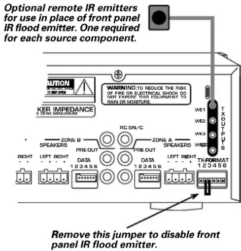
RMZ-955s are shipped with the front panel IR flood emitter engaged. However, there may be applications (system installations on open shelves in very large, bright rooms, for example) where the IR flood emitter might interfere with proper source component operation or will not be particularly effective in communicating control pulses. Or, there may be systems where an RSM-901 display/sensor located in the same room as the RMZ-955. In these cases, disable the front-panel flood emitter and use individual IR emitters connected the RMZ-955's rear panel and placed over each source components IR sensor.
To disable the IR flood emitter, remove the jumper wire between screws 2 and 3 of the TX FORMAT terminal block located on the lower right hand side of the RMZ-955's rear panel.
NOTE: There is a very low intensity red LED mounted behind the emitter's window which flashes whenever it is transmitting IR codes. Use this LED to verify the emitter's operating status.
Rear Panel IR Repeaters
In many system configurations, the most reliable, trouble-free means of passing IR control codes to the source components is with individual IR emitters, one for each source. Use these optional repeaters in situations where the RMZ-955 will be located some distance away from the source components or where the IR flood emitter may have difficulty transmitting reliable source control data. Disable the flood emitter when using the optional IR remote emitters.
The RMZ-955 rear panel has four paralleled 3.5mm mini-plug sockets labeled "TX OUTPUTS." They accept standard "stick on" IR emitter like Xantech's Video Link 282-00. Plug a repeater into one of the sockets and place it over the source component's IR sensor. Repeat for the other three sources.
Note: Some source components, such as some Rotel sources, allow a direct connection from a 3.5 mm rear panel IR emitter connection to a matching 3.5 mm connection on the source component, eliminating the need for stick-on IR emitters.
Paging Input
The paging input allows announcements to be made over the system, and, if required, for Zones to be momentarily muted, in conjunction with a doorbell or a phone system.
The paging feature needs to be activated from an external source via the "paging trigger" RCA-type input jack on the back of the RMZ-955. Any device which shorts the trigger input will cause the controller to enter its paging mode. For example, a doorbell, a phone system, or a keyed announcement microphone system could provide this control.
The "Paging Audio In" RCA jack is connected to the audio output of the announcement system (phone or microphone amplifier).
The "Paging Audio Output" jack can be connected to the Paging Audio Input on a second controller (in a large multi-controller system) or to the RCA input of an external amplifier.

flowchart
graph TD
    A["Door Bell"] --> B["Relay (if required)"]
    B --> C["Phone System"]
    B --> D["Microphone Amplifier"]
    C --> E["trigger trigger"]
    D --> F["passing audio output to paging audio input on second RMZ-955"]
    E --> G["UNIVERSITY AND 100V MAX AC/SDI/SH2"]
    F --> H["SPEAKING"]
    H --> I["4"]
    I --> J["OUT"]
    J --> K["DATA 1.2.3.4.5"]
    K --> L["4.7 MHz"]
    L --> M["OUT"]
    M --> N["OUT"]
Paging Inhibit
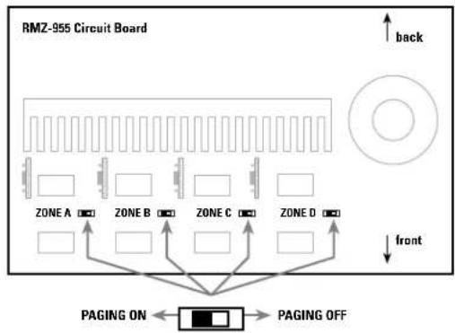
The paging function is individually configurable for each zone. The installer can select which Zones will receive or not receive an announcement when the paging is activated. Each Zone has an internal micro switch which is used to set the paging function ON/OFF for that zone. These switches are accessed by removing the top cover of the RMZ-955 by a qualified technician. Make sure that the AC power line is disconnected before removing the cover.
flowchart
graph TD
    A["Front"] --> B["Zone A"]
    A --> C["Zone B"]
    A --> D["Zone C"]
    A --> E["Zone D"]
    B --> F["PAGING ON"]
    C --> G["PAGING OFF"]
    D --> H["PAGING OFF"]
    E --> I["PAGING OFF"]
    J["Upward arrow labeled 'back'"] --> K["Top circular component"]
Notes:
If a Zone is in Standby (or is listening to Input 1, 2, or 3) and its paging switch is set to OFF, the Zone will remain in its present status when the paging is activated for the rest of the system. It will not be muted and no announcement will be heard.
If a Zone is listening to Input 4, the paging input will be heard when activated, regardless of whether its paging switch is set to ON or OFF.
Installation: Zone Control Devices
RSM-901 Sensor/Display
RSM-901 Mounting
The RSM-901 Sensor/Display mounts in a single-width wall box or in a double width box with the RKP-901 keypad.
PLACEMENT SUGGESTIONS: Exact placement will vary with each installation but we strongly recommend AGAINST placement where the RSM-901 will be exposed to direct sunlight, powerful fluorescent illumination or the output of a high intensity spotlight, etc. These light sources contain high levels of infrared energy themselves and may cause intermittent operation by saturating the RSM-901.
Note: Avoid infrared "loops" by making sure that an RSM-901 sensor/display is not placed where it might pick up signals from a source component's IR repeater or the RMZ-955's IR front panel flood emitter.
Lastly, make sure that each RSM-901 is on a relatively uninterrupted "line-of-sight" path to all likely locations from which the hand held RR-952 remote might be used. You'll find the RSM-901/RR-952 combination much less susceptible to signal interference than other IR remote control links, but planning will ensure dependable operation under an even wider variety of conditions.

RSM-901 Data Connections
Prepare the data cable with the supplied termination plug using the same color coding as previously described for the RMZ-955.
flowchart
graph TD
    A["ON"] --> B["DIP SWITCH"]
    B --> C["See instructions for configuration settings"]
    A --> D["RESET SWITCH SW1"]
    D --> E["Press after changing configuration"]
    A --> F["OFF"]
    F --> G["ON"]
    G --> H["JP1"]
    H --> I["JUMPER 1 install jumper to enable battery backup"]
    I --> J["OUTIN"]
    J --> K["INPUT DATA CONNECTOR Connect to RKP-901 Keypad or slave RSM-901 display/sensor"]
    J --> L["OUTPUT DATA CONNECTOR Connect to RMZ-955 controller/amplifier"]
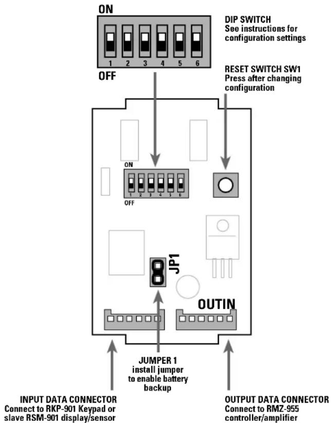
Note that each RSM-901 has two data terminals labeled "In" and "Out" respectively. Connect the remote zone end of the data cable from the RMZ-955 to the "Out" connector on the RSM-901.
The "In" connector is used to "daisy-chain" additional RSM-901 display/sensors or RKP-901 keypads in the same zone. See Zone Connection Strategies on page 15 for details.
A number of configuration settings must be made using the switches and jumpers on the back of the RSM-901. These are detailed below.
Battery Enable
Each RSM-901 has a rechargeable back-up battery which maintains the clock and configuration information when power to the controller is switched off. When fully charged, the battery will then maintain the configuration information for several weeks.
The battery must be enabled when the RSM-901 is installed. To enable the battery, place the jumper JP1 to link the two pins as shown in the illustration above.
Note: After initial installation, leave the RMZ-955 turned on continuously for a few days to ensure that the battery is charged.
Zone Configuration
Each RSM-901 must be configured or "addressed" as being in Zone A, Zone B, Zone C, or Zone D. You select the proper zone by setting Switches 1 & 2 on the DIP switch shown in the illustration. Use the following settings:
Zone Switch 1 Switch 2
A (default) OFF OFF
B OFF ON
C ON OFF
D O N O
Source Component Labels
Each RSM-901 must be configured to display the correct label for each source component. It always displays "Tuner" for source input 1 and "CD" for source input 2. However, source input 3 can display "Tape" or "Sat" depending on the setting of Switch 3 and source input 4 can display "CD2", "VCR", "Ld", or "DVD" depending on the setting of Switch 4 and Switch 5. Use the following settings:
Source Input 3 Switch 3
Tape (default) OFF
Sat ON
Source Input 4 Switch 4 Switch 5
CD2 ON ON
VCR ON OFF
LD OFF ON
DVD (default) OFF OFF
Note: Remember to set these switches on all RSM-901s.
Master/Slave Configuration
Each RSM-901 must be configured as a Master or Slave by setting Switch 6. Because it is possible to have more than one RSM-901 in any zone, follow the simple rules to ensure that the required functions are available:
Each zone used in a system must have a Master RSM-901. In a zone with more than one RSM-901, only one must be set as a Master and each other must be set as a Slave. The Master must be the first device on the data cable to the zone from the RMZ-955.
The Master/Slave settings for Switch 6 are:
| Master/Slave | Switch 6 |
| Master | OFF (default) |
| Slave | ON |
Note: Clock and Alarm functions can only be set from a Master.
System Reset
After changing any of the above configurations, reset the RSM-901 by pressing the RESET switch (SW1). This is essential to allow the new setting to take effect.
Source Component Set-up
After installation, refer to System Set-up and Programming (page 21) for configuring the proper data codes for source component operation.
Remember that an RSM-901 connected to the Zone A data cable terminal MUST be used for initial set-up, particularly in systems where non-Rotel source components are included.
Note: After completing the installation and component set-up, power down the system, wait approximately 30 seconds, and then power it up again. Test all functions.
RKP-901 Keypad

RKP-901 Mounting
The RKP-901 keypad mounts in a wall box in the same manner as the RSM-901 sensor/display. There are no restrictions on where the RKP-901 can be located. Common sense and user convenience should be the determining factors. Alternatively, the RKP-901 can be mounted in a double-width wall box with an RSM-901 sensor/display. This is the most sensible arrangement from an installation viewpoint (fewer cable runs) but may not be practical in all rooms.

RKP-901 Data Connections
RKP-901s do not need to be set for particular zones or configured as Master/Slaves because they do not display zone or system status information.
Data cable terminations and connections are made the same way as previously detailed. As does the RSM-901, each RKP-901 has two data terminals ("In" and "Out") located at the bottom of its circuit board. Connect the "Out" terminal, either to the "In" terminal of an RSM-901 in the zone, or to the RMZ-955 controller if the zone does not have a RSM-901.

Zone Connection Strategies
Each zone will support up to three RSM-901s and three RKP-901s. All of the command devices for one zone should connect to each other in serial fashion using their appropriate circuit board-mounted "In" and "Out" terminals.
Each RSM-901 signals when it receives and processes a command. This happens regardless of whether the command was generated by a keypad or a hand held remote. However, a keypad located "downstream" of a sensor/display will not trigger that sensor's command processing indicator.
Whenever possible, we suggest that you configure each zone so that all keypads are "upstream" from all sensor/displays. Although not always practical depending on the zone configuration, this arrangement will reduce user confusion.
Regardless of other considerations, we suggest that you always wire an RSM/RKP double wall box so that the RSM is located "downstream" from adjacent RKP (i.e., between the RKP and the RMZ-955 controller/amplifier). This assures that the sensor/display always signals the user when the adjacent keypad is used.
Installation is the first step towards enjoying an RMZ-955 system. Proper set-up ensures that the RMZ-955 will function optimally with all associated source components and provide total system control.
Installation: Multi-controller Systems
Each RMZ-955 provides independently controlled audio distribution from four sources to four separate zones. To satisfy the requirements of more elaborate systems, up to four RMZ-955s can be cascaded to build a system with as many as 16 independent zones. Under these circumstances, all RMZ-955 controller/amplifiers share one set of four source components.
When system complexity calls for more than one RMZ-955, we have no cautions about stacking controller/amplifiers on top of each other. As long as there is sufficient room to allow relatively unrestricted air flow, heat should not be a problem.
In most respects, installing a multi-controller system is no different than a single controller system. Source input connections, speaker output connections, data cable connections to the remote zones, and other configuration steps are essentially the same. Review Installation: RMZ-955 Controller(page 5) for complete information.
There are, however, some additional considerations and installation steps required for a system with multiple RMZ-955 controllers. These steps all deal with the need to link the controllers:
a) AC connections for fully-integrated system control
b) Sharing four sources among all controllers
c) Passing IR commands from one controller to the rest
d) Linking special features like system-wide paging
All hookup instructions in this section assume that Zones 1-4 will be handled by the first RMZ-955 (called "A"), Zones 5-8 by the RMZ-955 immediately above it ("B"), Zones 9-12 by third unit ("C"), and Zones 13-16 by the top unit ("D"). In most cases, we do not illustrate all four controllers, as additional controllers are merely added in the same fashion as the second or third controller.
There is no functional distinction between the first RMZ-955 and additional controllers in a system. However, for convenience and simplicity, we assume that the first controller will handle some additional responsibilities, such as source inputs and sending IR signals to the sources. This approach makes it easy on the installer, particularly when starting with a single RMZ-955 and later expanding with additional controllers. Essentially, the work done installing a single RMZ-955 remains unchanged and additional zones are handled by "add-on" RMZ-955 controllers.

For multi-controller systems, connect source sharing links (connections shown on left side), AC control links (connections shown in center), and IR repeater links (connections shown on right side).
AC Power
Multiple controller systems require handling AC connections in a way that allows any zone to "power up" or "power down" the system. In other words, there must be a provision for zones connected to additional RMZ-955 controllers to control the system's switched AC outlets.
A special feature of the RMZ-955, called "AC Link" simplifies the installation of multi-controller systems with a simple control line connection between units for AC control.
AC Connections
Plug all RMZ-955 controllers into unswitched AC outlets, providing a constant AC supply.
Plug all source components into the switched outlets located on the rear panels of the RMZ-955 controllers. As in a single-controller system, the recommended approach is to use a Rotel RLC-900 power conditioner/switcher in conjunction with the first RMZ-955's rear panel outlets. This allows the first RMZ-955 to handle all AC switching for the system.
With the "AC Linking" feature, it is also possible to plug source components into any switched outlet on the rear panel of any RMZ-955. All of these outlets are controlled in unison. When the system is "powered up" from any zone, the switched outlets on the first RMZ-955 and all other controllers are turned on. When a "power down" command is sent, all RMZ-955's go into standby and their rear panel switched outlets are turned off.
AC Link
Unified AC control in multi-controller systems is achieved by a special "AC Link" connection from the first RMZ-955 to the second and so on down the line. This connection uses standard 3.5 mm stereo mini-jacks at both ends of a 3-conductor cable.
Note: It is essential to use a stereo mini-jack for the "AC Link" connection between controllers (such as Radio Shack #274-389). Do not substitute a mono 2-conductor cable.
To make the connection, plug one end of the 3.5 mm stereo cable into the 3.5 mm jack labeled "Link Out" on the first RMZ-955. Then plug the other end of the cable into the jack labeled "Link In" on the second RMZ-955. Then link the second RMZ-955 by connecting its "Link Out" to the third RMZ-955's "Link In" jack with another cable. And, so on until there is an "AC Link" connection between all RMZ-955 controllers.
External 5V Trigger: Once you have completed all of the "AC Link" connections, the "Link Out" connector on the last RMZ-955 is still available. This jack can provide a +5V D.C. control voltage that could be used to activate external devices in an elaborate custom system. When the Rotel system is activated from any zone, this control signal goes to +5V. When the total system
"power down" command is given from any zone, the RMZ-955 controllers go into Standby mode, the rear panel switched AC outlets are shut off, and this control signal goes to 0V.
This external trigger requires the same 3.5 mm stereo mini-jack as the "AC Link" connections. The "tip" of the connector carries the +5V DC control voltage.
Manual AC Override
There is a provision to manually override the "AC Link" control of the switched outlets. While not common, there may be custom system configurations where being able to manually power up all of the switched outlets and components connected to them.
To enable the manual override, connect Pin 1 and Pin 6 of the rear panel TX FORMAT jumper block with a jumper wire. As long as these two pins are connected, the switched AC outlets on all RMZ-955's will be powered on. When the two pins are unconnected, control of the AC outlets will revert to standard control from the zones, depending on whether the system has been activated from a zone or not.
In practice, the manual override jumper described above would be replaced with a simple single-pole switch connected between Pin 1 and Pin 6 of the "TX-FORM" block. When the switch is closed, manual override is active. When the switch is open, activation of the AC outlets reverts to standard zone control.

To manually turn on all switched AC outlets, connect pins 1 & 6 with a jumper or closed switch

For automatic system control of switched AC outlets, remove jumper or open switch
Note: In multi-controller systems, Pin 6 must be connected from the first controller to the Pin 6 on the next, and so on daisy-changing all RMZ-955s to enable the manual override.
Source Connections
Multi-controller systems share the same four source components. Therefore, it is necessary to pass the signal from each source to all of the RMZ-955 controllers in a system.
Connect all sources to the first RMZ-955 per the instructions as shown Installation: RMZ-955 Controller on page 6.
Then, using standard shielded RCA-RCA audio interconnet cables, connect Source 1's "loop through" outputs on the first RMZ-955 "A" to the corresponding Source 1 inputs on the second RMZ-955 "B". Repeat this procedure for all four sources.
If a system requires a third RMZ-955, repeat this procedure but, this time, connect the "loop-though" source output on the second RMZ-955 "B" to the corresponding input on the third RMZ-955 "C" and so for a fourth controller "D".
NOTE: It is important to observe proper channel continuity when connecting source components to more than one RMZ-955.
IR Connections
Systems with multiple RMZ-955 controllers follow generally the same approach to distributing IR signals to the source components as a single RMZ-955 system. Therefore, review the section on IR installation, particularly on the choice of using the front-panel flood emitter or the back-panel "remote" emitter connections.
When 2 or more RMZ-955s are used in the same system, we suggest that you connect them so that only the first RMZ-955 distributes IR commands to the source components and that the IR emitter functions of all additional RMZ-955 controllers is disabled. This avoids potential interference leading to erratic operation, particularly when using the front panel IR flood emitters.
Note: This is a suggestion only and not a hard and fast rule. There may be some unusual system layouts which benefit from multiple RMZ-955s distributing IR to the sources. This option is covered below as an exception to the standard practice.
The general approach to configuring IR connections for multi-controller systems involves three steps:
a) Configure the first RMZ-955 "A" to distribute IR codes to the sources (either through its front-panel flood emitter or its "remote" IR emitters as described in the section on installing single controller systems.
b) Disable the flood emitter on all other RMZ-955 controllers by removing the "TX-Form" jumper connecting Pins 2 and 3.
c) Relay IR codes from additional RMZ-955 controllers to the first one by installing a series of jumper wires connected to the "TX-Form" terminal block as outlined below.
Use the following connections for multiple RMZ-955 systems:
For 2 RMZ-955s (5 to 8 zones):
- Remove the jumper between terminals 2 & 3 of the TX FORMAT block on RMZ-955 "B" to disable its IR flood emitter. Leave the jumper in place on RMZ-955 "A" if you are using its front-panel flood emitter. Remove the jumper if you are using remote IR emitters connected to the back panel of RMZ-955 "A".
- Link IR signals to the first controller by connecting terminal 3 of the RMZ-955 "B" TX FORMAT block to terminal 4 on RMZ-955 "A". This completes the IR signal link to the IR flood or "remote" emitter on RMZ-955 "A".

Use this jumper arrangement with 3 RMZ-955 controllers. Disables the IR flood emitters on all but the first controller. Remove gray jumper if using back panel IR repeaters from the first RMZ-955 instead of the flood emitter.
For 3 RMZ-955s (9-12 zones):
- Remove the jumpers between terminals 2 and 3 of the TX FOR-MAT blocks on RMZ-955 "B" and "C" to disable their flood emitters. Leave the jumper in place on the first RMZ-955 "A" to use its front-panel flood emitter. Remove this jumper as well do disable the flood emitter when using remote IR emitters.
- Connect terminal 3 of the RMZ-955 "C" TX FORMAT block to terminal 4 on RMZ-955 "B".
- Connect terminal 3 of the RMZ-955 "B" TX FORMAT block to terminal 4 on RMZ-955 "C". This completes the signal link to the IR flood emitter on RMZ-955 "A" from the other two RMZ-955s.
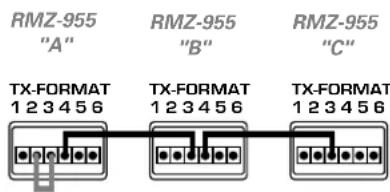
Use this jumper arrangement with 3 RMZ-955 controllers. Disables the IR flood emitters on all but the first controller. Remove gray jumper if using back panel IR repeaters from the first RMZ-955 instead of the flood emitter.
For 4 RMZ-955s (13-16 zones):
- Remove the jumpers between terminals 2 and 3 of the TX FOR-MAT blocks on RMZ-955 "B" and "C" and "D" to disable their flood emitters. Leave the jumper in place on the first RMZ-955 "A" to use its front-panel flood emitter. Remove this jumper to disable the flood emitter when using back panel IR repeaters.
- Connect terminal 3 of the RMZ-955 "D" TX FORMAT block to terminal 4 on RMZ-955 "C".
- Connect terminal 3 of the RMZ-955 "C" TX FORMAT block to terminal 4 on RMZ-955 "B".
- Connect terminal 3 of the RMZ-955 "B" TX FORMAT block to terminal 4 on RMZ-955 "C". This completes the signal link to the IR flood emitter on RMZ-955 "A" from the other two RMZ-955s.

Use this jumper arrangement with 4 RMZ-955 controllers. Disables the IR flood emitters on all but the first controller. Remove gray jumper if using back panel IR repeaters from the first RMZ-955 instead of the flood emitter.
Exception: Multiple IR Flood Emitters
As stated above, the general practice is to send IR commands to the source components from only the first RMZ-955 and to disable the flood emitters on all other RMZ-955 controllers. The purpose of this rule is to prevent IR signals from two different flood emitters interfering with each other and confusing the source component.
An exception to this general rule might arise in systems where some source components are housed in one closed cabinet and others in a different closed cabinet. In this case, you may wish to use two or more RMZ-955 controllers, one in each cabinet, to distribute the IR signals from their flood emitters to the source components.
This can be accomplished with a jumper wire from Terminal 2 of the first RMZ-955's TX-Form block to Terminal 2 on any other RMZ-955 that needs to have its front-panel flood emitter activated.
For example, the gray jumper wire in the following illustration is used to activate the front-panel flood emitter on RMZ-955 "B" in addition to "A".
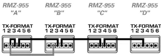
Use this jumper arrangement to enable the front panel IR flood emitters on the first two RMZ-955s.
Here, the gray jumper wire is used to activate the flood emitter on all four RMZ-955 controllers:

Use this jumper arrangement to enable the front panel IR flood emitters on all four RMZ-955s.
Paging Connections
When using the Paging feature in a multi-controller system, two additional installation steps are required. See page 11 for an overview of the paging feature.
a) To trigger the muting and/or paging function, it is necessary to connect the Paging Trigger input to all RMZ-955 controllers. This requires making multiple connections from whatever device or mechanism is used to supply a shorting input.
b) For announcements to be heard in all zones connected to all RMZ-955s, the paging audio signal must be distributed to all controllers. This can be done by connecting the Paging Audio Output on the first RMZ-955 to the Paging Audio Input on the second RMZ-955, using a standard RCA to RCA interconnect cable. Repeat this connection from the second to the third controller and from the third to the fourth, if necessary.
Notes on multi-controller set-up
Power Toggle Set-up
We recommend in systems with multiple RMZ-955 controllers (with full AC control from any Zone) that you select source components that do not require a "power toggle" command, i.e. components that fully power up when AC power is applied, instead of going into a standby mode.
If sources requiring a "power toggle" command are used, only one RMZ-955 controller should have the "power toggle" feature activated (i.e. set to "y" during setup). Make sure that the "Power Toggle" command is DEACTIVATED for all other RMZ-955(s).
Even though the default "Power Toggle" setting is OFF, verify that this has not changed by temporarily connecting an RSM-901 to the Zone A data terminal of each remaining RMZ-955, entering Set-up Mode as outlined and pressing the RLC-900 "n" (for No) key. Continue to hold the "n" key and press the other set-up key "y" to exit setup.
This is a critical step in a system using multiple RMZ-955s. If the "Power Toggle" is not deactivated for the additional RMZ-955(s), source components will not turn on and off properly — in fact, source components may actually turn off when RMZ-955s turn on.
Source Component Set-up
Programming of command code sets for source components is covered in the following section of the manual. However, keep in mind that in systems with multiple RMZ-955 controllers, it will be necessary to reprogram these codes for each RMZ-955 in the system. This must be done from an RSM-901 sensor display connected to Zone A on each controller.
"Engaged" Indicator
The "Engaged" indicator on a remote zone's RSM-901 sensor/display(s) will indicate other same-source users only in zones connected to that particular RMZ-955 controller/amplifier.
For example, in an 8-zone system using two RMZ-955s, a CD listener in Zone 7 (connected to the second RMZ-955) would have no indication that another user in Zone 2 (connected to the first RMZ-955) was listening to the same source. If a third listener in Zone 4 then selected CD, only the listeners in Zones 2 and 4 (both connected to the same RMZ-955) would know that someone else was sharing the same source.
System Set-up & Programming
Source Commands
The RMZ-955 is factory set for use with Rotel source components, including Rotel multi-disc CD players. No adjustments are necessary for these components.
In addition to Rotel source components, the RMZ-955 can be set to operate the following:
Input 1 Tuners: Rotel, Sony, Pioneer, Yamaha, Denon
Input 2 CD: Rotel, Sony, Pioneer, Yamaha, Denon, RC5
Input 3 Tape Deck: Rotel, Sony, Pioneer, Yamaha, Denon Satellite TV: RCA, Sony
Input 4 CD 2: Sony, Pioneer
Laser Disc: Pioneer
VCR: Sony, Panasonic
DVD Player: Pioneer, Toshiba
Note 1: Assign each type of component to the input specified above so that the label displayed by the RSM-901 (Tuner, CD, etc.) matches the component when each input is selected. Note 2: Two CD players of the same brand cannot be used in the same system. Chose a different brand for CD.2
Source Command Set-up
a) Locate Zone A's RSM-901 sensor/display. Source command sets cannot be changed from any other Zone or even from Zone A's keypad. If in doubt, send a command with the RR-952 hand held remote and monitor Zone A's green Code LED on the RMZ-955's front panel: it will flash when the RMZ-955 recognizes and processes a command.
Note: Remember that any RSM-901 sensor/display can be connected to the Zone A data terminal for this procedure. Even if Zone A is equipped with a wall mounted sensor/display, it is probably more convenient to temporarily disconnect the data cable from that unit and substitute another RSM-901 placed near the RMZ-955 and source components.
To avoid the possibility of an IR loop when using an RSM-901 located near the RMZ-955, temporarily remove the jumper between Terminals 2 and 3 of the TX FORMAT terminal block on the rear panel of the RMZ-955. Also make sure that any RSM-901 used in this set-up sequence has the circuit board DIP switches set for Zone A and "Master" (See page 13).
b) Select an input (Tuner, CD, Tape/Sat, or VCR/DVD) on the RR-952 so that the corresponding label shows on Zone A's RSM-901 sensor/display.
c) Place the Set-up Card over the RR-952's pushbuttons.
d) With the RR-952 pointing at the RSM-901 sensor/display, enter "Set-up" mode by pushing both Set-up buttons simultaneously for a few seconds until the RSM-901 displays "Set?", indicating that the system is awaiting further instructions.

e) Push the desired command code button for the component you want to change. The available choices for that input are grouped together on the Set Up Card. Upon receiving your selection, the RSM-901 will display one of the following characters to indicate your choice of custom command sets:
A Rotel Tuner
B Rotel CD Changer RCC-945
C Pioneer LD/DVD
D Rotel Tape Deck
E Sony Tuner
F Sony CD
G Sony CD 2
H Sony Tape Deck
I Pioneer Tuner
J Pioneer CD
K Pioneer CD 2
L Pioneer Tape Deck
M Yamaha Tuner
N Yamaha CD
O Panasonic VCR
P Yamaha Tape Deck
Q Denon CD
R Sony VCR
S Denon Tape Deck
T Denon Tuner
U Rotel CD Changer RCC-935
V RCA DSS Sat TV
W Toshiba DVD
X Sony DSS Sat TV
f) Repeat the above procedure for the other inputs. After you've selected the command codes for all the component categories you wish to change, exit "Set-up" by holding the right-hand SET-UP 2 button and pushing the left-hand SET-UP 1 button. The word "SAVE" will appear on the RSM-901 display to indicate that the new configuration has been memorized.
g) For the new command sets to take effect, the RMZ-955 must be turned OFF (using the front panel power button) and then turned ON again after 30 seconds.
All changes are stored in non-volatile memory and can not be accidentally erased, even by unplugging the RMZ-955. The only way to change command code operation is to access Set-up mode again.
Note: See Page 5 for further details on the "Power Toggle" command required when the RMZ-955 system (and associated source components) use the switched outlet or recommended RLC-900 Power Line Conditioner as an AC power source.
Power Toggle
If you choose to power source components from the RMZ-955's Switched AC outlet and your system includes components which normally power on in a standby mode, you will need to ACTIVATE the RMZ-955's software-based "Power Toggle" command.
The "Power Toggle" command fully activates these components even though they usually go into a quiescent or Standby mode when first plugged into the wall or when AC power becomes available.
Source components connected through a switched outlet or the RLC-900 are totally disconnected from AC when the outlets are switched off. Consequently, when the RMZ-955 first activates the source components, some go into a "standby" mode where a few sensors and microprocessors are powered but where major circuitry blocks are still inactive. The "Power Toggle" command tells the sensors and microprocessors to "wake up" the rest of the component.
The following steps will illustrate how the "Power Toggle" command works:
- RMZ-955 in "Standby" mode, source components OFF.
- Zone activation command received. RMZ-955 ON, Switched AC outlet activated, source components switched ON or to "Standby" mode.
- RMZ-955 sends "Power Toggle" command to source components. "Power Toggle" triggers change from "Standby" to "On".
- All source components ready for remote zone use.
The "Power Toggle" command default is OFF but it can be easily activated. "Power Toggle" is activated or deactivated depending on which of the two SET-UP bottoms is pressed first when exiting the Set-up Mode. Press the "y" (for Yes) key first to activate "Power Toggle". Continue holding the "y" key and press the "n" key to exit Set-up. This activates the RMZ-955's software-based "Power Toggle" command.
If source components are powered directly from an AC wall outlet, make sure the "Power Toggle" command is DEACTIVATED (the RMZ-955's default condition) and that any source components featuring a "Standby" mode are "ON" before using the RMZ-955. To deactivate "Power Toggle", press and hold the "n" key first. Then, press the "y" key to exit Set-up.
Operating Instructions
As detailed in above, the RMZ-955 should ALWAYS be plugged into an uninterruptable AC source. This ensures that essential RMZ-955 system benefits such as remote controlled zone activation and source selection are always available. Zone control devices (the RKP-901 keypad and RSM-901 sensor/display) are powered from the data cables and are always active as long as the RMZ-955 is connected to AC.

RR-952 Hand-held Remote
The RR-952 remote provides easy and convenient system operation from any zone equipped with a RSM-901 sensor/display. You will find that the RR-952/RSM-901's operating range is longer and the angle of acceptance is wider than with many other hand held controllers. This increased operating convenience is a direct result of a more powerful transmitter in the remote and more sensitive receiving circuitry in the sensor/displays. Enjoy the difference.
To use the RR-952 remote control, simply aim it at a wall-mounted RSM-901 sensor/display.
Input Selector Buttons
These buttons provide "one-touch" operation of the system, playing the selected source component in the requesting zone. The actual function of the buttons depends on the current system status, but the net effect is the same: activate the system (if necessary), select the desired component, put it in play mode (if necessary), and direct its signal to the local zone.
Depending on system status, pressing any of these buttons will do one of the following:
a) If the entire system is "Off" (i.e., the RMZ-955 is in "Standby" mode and all source components are either Off or in "Standby"), pressing any input selector button will activate the entire system (including source components) for distribution as requested.
b) If only the requesting zone is in "Standby" (and the rest of the system, including sources, is active), selecting an input will enable that zone's microprocessor-controlled switching circuitry and direct that source's output to the requesting zone. If the requested source is not already in use by another zone, selecting the source will also engage Play mode.
c) If the requesting zone is already playing a source, pushing another input selector button will simply choose the new source.
d) Input selector buttons for CD, TAPE and VIDEO double as "Play" command buttons for their respective sources. This is important when a source is in "Pause" mode: Simply press the proper input selector again to resume play.
Tuner control buttons
FAV STN (Favorite Station): This will select the first station (Pre-set #1) programmed into the tuner's memory.
- PRESET +: These select the next PRE-PROGRAMMED station lower or higher in frequency than the one playing.
CD control buttons
RANDOM: This instructs the CD player to play tracks (and discs for multi-disc changer) in whatever random order the CD player chooses.
DISC: This advances the CD player to the next available disc. (functional only with multi-play CD players)
◀ SKIP ▶ These advance the CD player to the next track, backward or forward, on the disc being played.
STOP: This stops the CD player. Press the CD button to resume playing.
Tape/Satellite TV control buttons
STOP: This button stops tape. Press the TAPE/SAT button to resume playing.
(Rewind): This rewinds the tape. Press the TAPE input select pushbutton to put the deck back into PLAY mode again. For Satellite TV, this changes to the next lower channel.
▶▶ (Fast forward): Same as above but in the opposite direction. For Satellite TV, this changes to the next higher channel.
Video/LD control buttons
STOP: Stops the video tape or disc. Press the VIDEO/LD button to resume playing.
PAUSE: This button momentarily stops disc play until it is pushed again.
- CHNL: If a DVD disc is playing, this button backs up to the beginning of that track and continues playing. Two quick pushes backs the player to the beginning of the PREVIOUS track or chapter. If a VCR is selected, this changes its tuner to the next lower channel. If CD2 is playing, this button selects "Random Play"
CHNL +: If a DVD is playing, this button goes forward to the beginning of the next track. If a VCR is selected, this changes its tuner to the next higher channel. If CD2 is playing, this button selects the next disc.
◀◀ (Reverse Scan): This begins a high speed reverse scan useful for returning to a desired point in a movie, etc. Press the VIDEO/LD input selector button to go back to Play mode when you've reached the desired point on the disc. If CD2 is playing, this button skips to the beginning of the current track.
▶▶ (Forward Scan): The same as above but in the opposite (i.e., forward) direction.
Mute
This temporarily reduces zone volume to very quiet levels for telephone conversations, etc. Press Mute again to restore original volume settings. You can also press Volume Up, Volume Down or any Input button to restore original levels.
VOLUME UP/VOLUME DOWN
Nothing surprising here – simply press the appropriate button to increase or decrease playback levels as desired.
STBY
This button has two functions:
a) A brief push will put the Zone from which the command originated into Standby status. All other zones will remain unaffected. Source components will remain on.
b) A continuous push (more than 4 seconds) performs a total system-wide "power down".
This system "power down" includes deactivating all zones, shutting off AC power to all components connected to the RMZ-955's switched AC outlets, and putting all RMZ-955's in standby mode.
"X"
Reserved for future use and inoperative at the present time.
Note: Should you need more advanced IR controls for a particular source, you may be able to use the source's own dedicated IR remote control. In most cases, the RSM-901 and the IR repeater system will be able to pass IR codes directly to the source from any remote control.
RKP-901 Keypad

The RKP-901 keypad offers easy access to most RMZ-955 system functions. The major functional difference between the RKP-901 keypad and RR-952 hand held remote controller is that the wall-mounted keypad has only twelve keys.
Input Select commands
These buttons provide "one-touch" operation. If the system is currently inactive, pushing any of the four input source selection buttons will "power up" the RMZ-955's and the source components, send the play command to the selected source, and send the signal from that source to the zone from which the button is pushed. Assuming the tuner is tuned to a station, a disc in the CD player, etc., you will hear music with the push of a single button.
The function of the button changes slightly if the system is already active. For example, if the source selected is already playing in another zone, pushing the Input Select button will not send a Play command, but will simply let you hear what is already playing. If your zone is already active, pressing an Input Select button lets
you hear a different source, sending a Play command if necessary. Finally, the Input Select button can be used as a Play button to resume operation following a previous Pause command.
The details are not important. If you want to hear a source in your room, just press the Input Select button for that source and the system will worry about the details for you.
TUNER: Selects the tuner as the active source.
CD: Selects the CD player as the active source and sends the play command to begin operation, if necessary.
AUX: Selects the source component connected to Input 3 (tape deck, or satellite TV) as the active source and sends the play command to begin operation, if necessary.
VIDEO: Selects the video component (VCR, CD2, or DVD) as the active source and sends the play command, if necessary.
System commands
- VOLUME +: Press to decrease or increase volume.
MUTE: Temporarily reduces system volume to almost full attenuation. Restore preselected volume levels by pressing MUTE again, VOL+, VOL− or any input selector.
OFF: A brief push puts the Zone from which the command is sent in Standby status. All other zones are unaffected. A continuous push of more than 4 seconds will send a stop command to all source components and power down the entire system.
Source Control Commands
◀ and ▶: These buttons are "up" and "down" controls for operating source components. Their function varies depending on the type of source currently active. See chart below.
DISC: This advances a multi-disc CD player to the next available disc. This button has no function for other components.
*: This button is a multi-purpose control, depending on the currently active source component. For most source components, it will send the STOP command to the source. However, it may also be used for a special function on some components. See chart.
| ◀ | ▶ | * | DISC | |
| CD PLAYER | Track skip (back) | Track skip (forward) | Random/Shuffle Play | Next Disc |
| TUNER | Preset – | Preset – | Favorite Station | No function |
| VIDEO (LD) | Chapter Skip (back) | Chapter Skip (forward) | Stop | No function |
| VIDEO (CD2) | Track Skip (back) | Track Skip (forward) | Random/Shuffle Play | No function |
| VIDEO (VCR) | F. Rewind/Scan | F. Forward/Scan | Stop | No function |
| VIDEO (DVD) | Skip Back | Skip Forward | Stop | No function |
| AUX (TAPE) | Rewind | Fast Forward | Stop | No function |
| AUX (SAT) | Channel (down) | Channel (up) | No function | No function |
RSM-901 Sensor/Display
The RSM-901 sensor/display receives IR signals from the RR-952 hand held controller and other IR devices. It also provides feedback on system status through a dot matrix LED display and indicators. In addition, it provides convenience features including a time of day display and a "wake to music" alarm clock function.
Note: The RSM-901 passes remote control IR commands to the RMZ-955 controller at any time, regardless of whether its zone is currently active or not.

Controls and Displays
Dot Matrix Display: Shows a variety of system and zone status information, including time of day (when the zone is inactive) and source component selection (when the zone is active).
RECEIVE LED: Flashes when the RSM-901 receives an IR control code from the RR-952 handheld remote or RKP-901 keypad.
PM LED: Lights up when the 12 hour clock time is after 12 noon and before 12 midnight.
ALARM LED: Lights to show that the "wake to music" alarm has been set and will execute at the set time, activating ONLY the Zone from which is has been set, not the whole system. If this LED is not lit, no alarm is in effect.
MODE Button: Used to set and activate various RSM-901 functions, including setting the time, setting the alarm, etc.
HOUR Button: Used in conjunction with the MODE button to set up the RSM-901. It has no function when the Zone is active.
MIN Button: Used in conjunction with the MODE button to set up the RSM-901. It has no function when the Zone is active.
Dot Matrix Display
The dot matrix display shows the following status information:
Clock Display and Greeting: When the Zone is INACTIVE, the display shows the current time of day in a 4-digit 12-hour format.
When the Zone is first activated, a time-appropriate greeting will display momentarily, followed by a display of the selected source component. To check the time while the Zone is ACTIVE, press the MODE button.
Source Selected: When the Zone is ACTIVE, the display shows the selected source component:

Engaged Indicator: It is useful to know when someone in another Zone is listening to the same source component that is active in your zone. If your Zone has exclusive use of the active source, the Source indicator's first character will be a capital letter. If the source is "engaged" or being shared with another zone, the first character will change to lower case.

Exclusive use of source

Source engaged in another zone
Volume Level: When the Volume setting is changed in the Zone, the RSM-901 will momentarily display the new setting:

Minimum Volume Maximum Volume

When a MUTE signal is sent, the volume display will ramp down to zero and show the message "MUTE". When the Zone is unmuted, the display will ramp up to its previous level.
If a Paging signal is received, the display will ramp down to zero and show a “(())” message during the page. If the Zone is muted, the Paging indicator will show immediately. If the Zone is in standby, the Paging indicator will be preceded by the turn-on greeting.
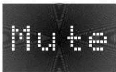
Muting Indicator Paging Indicator
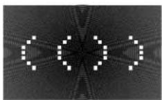
Setting Alarm, Time, and Custom Functions
The following custom functions are programmed from the RSM-901's Set-Up mode:
- Activating Wake-up Alarm
- Setting Alarm Time
- Setting default source that plays when Alarm activates
- Setting Time of Day
To enter the Set-Up mode, press the MODE button when the Zone is in stand-by mode (clock display showing). Continuing to press the MODE button will toggle through the four set-up choices above and then back to the standby mode.
After the first function has been selected, the RSM-901 will automatically exit the Set-Up mode and return to stand-by status if no button is pressed for approximately 10 seconds. Any changes made to the set-up configuration will be stored.
To set the alarm and time, press the MODE button to step through the following procedure. The diagrams show momentary indications of the functions being set prior to their status being shown.
a) Turning Alarm ON or OFF:
Press the MIN button to activate the wake-up alarm. Press the HOUR button to deactivate. The ALARM LED reminds you that the alarm has been activated. When finished, press the MODE button to record your changes and advance to the next step.

b) Setting Alarm Time:
The display will show the last alarm time set. Use the HOUR and MINUTE buttons to advance to the desired Alarm time. Make sure that the PM indicator shows the desired 12 hour period for the alarm. When finished, press the MODE button to record your changes and advance to the next step.

c) Select the Default Source:
Select the source component that you want to begin playing when the alarm goes off. Press the HOUR button to select the TUNER. Press the MINUTE button to select the CD (make sure there is a disc in the player). When finished, press the MODE button to record your changes and advance to the next step.

d) Setting Clock Time:
The display will show the current time of day. Use the HOUR and MINUTE buttons to make any changes. Make sure that the PM indicator shows the correct 12 hour period. When finished, press the MODE button to record changes and exit the Set-Up mode.
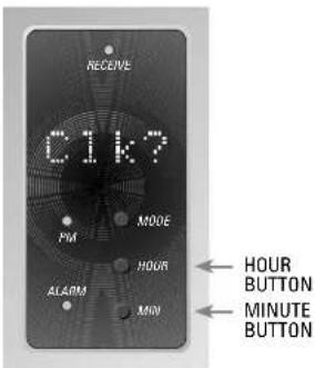
Note 1:
The clocks in different zones may be slightly out of synch due to drift or inaccurate setting. They will be re-synchronized automatically with the master system clock in Zone A at 12 noon each day.
Note 2:
If a RSM-901 is set as a SLAVE (see Page 13), only the clock can be set. Only one alarm in each zone is permitted and it must be set from the MASTER RSM-901 in each zone.
For Assistance
We hope this manual has been of assistance in planning and installing your multi-room sound distribution system. Although we've gone to great lengths to make this as complete as possible, we're sure we haven't covered every aspect of every possible system installation. Please feel free to contact our Technical Support department if you have any questions.
Rotel of America
54 Concord Street
North Reading, MA 01864-2699
Phone: 978-664-3820
Fax: 978-664-4109
In addition, your local Rotel Authorized retailer is an invaluable source of information and assistance, particularly in the area of custom audio systems.
Thank you very much for purchasing a Rotel system.
RMZ-955
MULTI-ROOM SYSTEM
The Rotel Co., Ltd.
10-10 Shinsen-Cho
Meguro-Ku
Tokyo 150, Japan
Phone: +81-3-5458-5325
Fax: +81-3-5458-5310
Rotel of America
54 Concord Street
North Reading, MA 01864-2699
Phone: 978-664-3820
Fax: 978-664-4109
Rotel Deutschland
Kleine Heide 12
D-33790 Halle/Westf., Germany
Phone: 05201-87170
Fax: 05201-73370
- Installation & Operation Manual
- CAUTION
- APPLICABLE FOR USA, CANADA OR WHERE APPROVED FOR THE USAGE
- WARNING:
- The RMZ-955 must be connected to a power supply only of the type and voltage specified on the rear panel of the unit.
- Getting Started 4
- Installation: RMZ-955 Controller 8
- Installation: Zone Control Devices 15
- Installation: Multi-controller Systems 18
- System Set-up & Programming 24
- Operating Instructions 26
- Getting Started
- Controlling the Remote Zones
- System Flexibility
- System Highlights
- Component Description
- System Planning
- RSM-901/RKP-901 Combination
- Placement
- Connections:
- IR Flood Emitter
- IR Repeater Jacks
- System Wiring Considerations
- Data Cable and Connectors
- Speaker Cables
- Zone Configuration
- Basic Zone Complement
- Loudspeakers
- Installation: RMZ-955 Controller
- AC Line Connections
- AC for the RMZ-955
- AC for Source Components
- Rotel RLC-900 AC line conditioner/switcher
- Special AC features
- Source connections
- Source inputs
- Source outputs
- Speaker Connections
- Preamp outputs
- Variable vs. Fixed Level
- Data cable connections
- DATA CONNECTOR WIRING CODE
- Infrared Control System
- Front Panel IR Flood Emitter
- Rear Panel IR Repeaters
- Paging Input
- Paging Inhibit
- Notes:
- Installation: Zone Control Devices
- RSM-901 Sensor/Display
- RSM-901 Mounting
- RSM-901 Data Connections
- Battery Enable
- Zone Switch 1 Switch 2
- Source Component Labels
- Source Input 3 Switch 3
- Source Input 4 Switch 4 Switch 5
- Master/Slave Configuration
- System Reset
- Source Component Set-up
- RKP-901 Keypad
- RKP-901 Mounting
- RKP-901 Data Connections
- Zone Connection Strategies
- Installation: Multi-controller Systems
- AC Power
- AC Connections
- AC Link
- Manual AC Override
- IR Connections
- For 2 RMZ-955s (5 to 8 zones):
- For 3 RMZ-955s (9-12 zones):
- For 4 RMZ-955s (13-16 zones):
- Exception: Multiple IR Flood Emitters
- Paging Connections
- Notes on multi-controller set-up
- Power Toggle Set-up
- "Engaged" Indicator
- System Set-up & Programming
- Source Commands
- Source Command Set-up
- Power Toggle
- Operating Instructions
- RR-952 Hand-held Remote
- Input Selector Buttons
- Tuner control buttons
- CD control buttons
- Tape/Satellite TV control buttons
- Video/LD control buttons
- Mute
- VOLUME UP/VOLUME DOWN
- STBY
- "X"
- Input Select commands
- System commands
- Source Control Commands
- Controls and Displays
- Dot Matrix Display
- Setting Alarm, Time, and Custom Functions
- a) Turning Alarm ON or OFF:
- b) Setting Alarm Time:
- c) Select the Default Source:
- d) Setting Clock Time:
- Note 1:
- Note 2:
- For Assistance
- Rotel of America
- RMZ-955
- MULTI-ROOM SYSTEM
Brand : ROTEL
Model : RMZ-955
Category : Controller