Energy Storm 3100iER-EFI - Generator Lifan - Free user manual and instructions
Find the device manual for free Energy Storm 3100iER-EFI Lifan in PDF.


| Product Type | Digital Inverter Generator |
| Brand | Lifan |
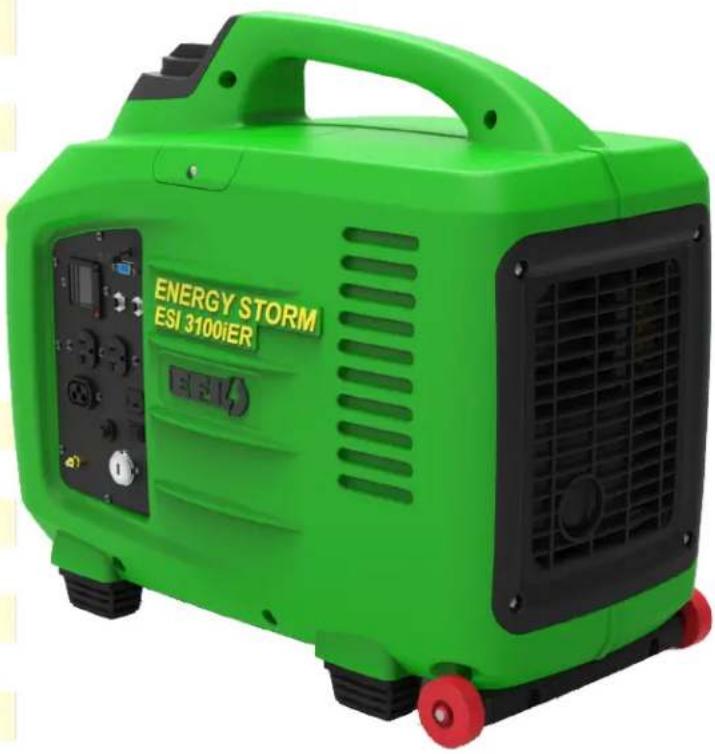
| Model | Energy Storm 3100iER-EFI |
| Dimensions (L x W x H) | 20 in. x 13 in. x 23 in. |
| Weight | 75 lbs |
| Rated AC Output | 3100 watts |
| Surge AC Output | 3200 watts |
| AC Voltage | 120V |
| AC Frequency | 60 Hz |
| DC Output | 12V, 8.3A |
| Engine Displacement | 150 cc |
| Fuel Type | Automotive unleaded gasoline (≤10% ethanol) |
| Fuel Tank Capacity | 2 gallons |
| Run Time at 50% Load | 5 hours |
| Starting System | Recoil and electric start (remote key fob) |
| Oil Type and Capacity | SAE 10W-30, 20 oz. |
| Parallel Capability | Yes (Duo Power, requires optional control box) |
| Noise Level at 7m | 61 dB |
| Safety Features | Low oil shutdown, CO warning, overload protection, spark arrestor |
| Warranty | 1 year parts and labor (residential), 12 months parts and labor (commercial) |
Frequently Asked Questions - Energy Storm 3100iER-EFI Lifan
User questions about Energy Storm 3100iER-EFI Lifan
0 question about this device. Answer the ones you know or ask your own.
Ask a new question about this device
Download the instructions for your Generator in PDF format for free! Find your manual Energy Storm 3100iER-EFI - Lifan and take your electronic device back in hand. On this page are published all the documents necessary for the use of your device. Energy Storm 3100iER-EFI by Lifan.
USER MANUAL Energy Storm 3100iER-EFI Lifan
Operating Instructions & Owners' Manual
Please read this manual carefully before operating your new inverter generator. (CA) in the model number designated California Compliant by CARB 8/31/2016
LIFAN POWER USA
OPERATING INSTRUCTIONS AND OWNER'S MANUAL
Energy Storm Series ESI-3100iER-EFI
ENGINE ID # IS STAMPED ON CRANK CASE

PLEASE KEEP AND READ THIS MANUAL CAREFULLY BEFORE OPERATING YOUR NEW LIFAN POWER USA DIGITAL INVERTER GENERATOR
RECORD PURCHASE HERE
MODEL #
ENGINE ID #
DATE OF PURCHASE
PURCHASE LOCATION
-CA INDICATES THIS UNIT IS CARB CERTIFIED
ATTENTION: Rental Companies and Private Owners who loan this equipment to others!
All persons to whom you rent/loan this inverter generator must have access to and read this manual. Keep this owner's manual with the inverter generator at all times and advise all persons who will operate the machine to read it. You must also provide personal instruction on how to safely set-up and operate the inverter generator and remain available to answer any questions a renter/borrower might have.
Only Trained Adults should set up and operate this equipment. DO NOT LET CHILDREN OPERATE THIS EQUIPMENT!
Always wear safety apparel when operating this equipment, safety glasses, ear protection, insulated waterproof gloves, and non-slip protective shoes are recommended. When using any cleaning chemicals refer to the chemical label for safety instructions concerning those chemicals for use of a respiration mask.
Never operate or let anyone operate this equipment while under the influence of any alcohol, drugs, or medication or when fatigued.
Owner's Manuals are available from Lifan Power USA at 1-866-471-7464.

WARNING
SPECIAL HAZARDS
• CO Poisoning: Exhaust from engine contains carbon monoxide, a poisonous gas that can cause carbon monoxide poisoning and possible death if inhaled.
- Injection Injury: High-pressure spray can pierce skin and underlying tissues, leading to serious injury and possible amputation. Such an injection injury can result in blood poisoning and/or severe tissue damage.
- Flying Debris: High-pressure spray can cause flying debris and possible surface damage.
- Electric shock: Operating equipment in wet conditions or near water can cause electric shock.
- Chemical Exposure: Cleaning chemical vapors or contact with skin may be hazardous.
- Fire/Explosion: Engine sparking can ignite fuel or other flammable liquids or vapors in the vicinity. Hot exhaust from engine can ignite combustible materials.
- Burns: Inverter Generator pump & engine are hot surfaces that can cause burn injuries.
EQUIPMENT PROTECTION FACTS
Inspect Upon Delivery: FIRST! Inspect for missing or damaged components. See “Initial Set-Up/Installation” section for where to report missing or damaged parts.
Add Engine Oil: Engine is shipped without oil. See the “Engine Manual” section of this manual for instructions on capacity and viscosity recommendations.
Maintenance Schedule: Engine requires periodic inspection and servicing to keep generator functioning efficiently. See “Maintenance Schedule Summary” for frequency of servicing.
TABLE OF CONTENTS
Preface 6
Product Specifications 7
Safety Instructions 8
Controls and Features 12
PRE-OPERATING INSTRUCTIONS ..... 17
Assembly 18
Auto Idle Control Switch / Duo Power ..... 19
Setup 20
Understanding Your Battery 24
Battery Assembly & Maintenance 23
Safety 26
Starting Your Generator 28
Operation of Generator 29
Storing The Unit 32
Maintenance 33
Transporting The Unit 38
Long-Term Storage 38
Short-Term Storage 39
Exercising The Generator 40
Troubleshooting 40
Powering 12V DC Devices 42
Jump-Starting The Generator 43
Digital Display 44
Error & Fault Codes 45
Wattage Chart 46
Limited Warranty Policy 50
Appendix: Exploded View / Parts List ..... 53
Appendix: Wiring Diagram 59
PLEASE READ THE FOLLOWING INSTRUCTIONS!
- Unit Shipped without engine oil. See Preoperating Instructions for further information.
- For repair under Warranty or questions concerning Warranty, DO NOT RETURN this product to the Store where purchased. Follow the procedures as outlined in the “WARRANTY POLICY” and “WARRANTY REGISTRATION” in the Owner’s Manual. For any questions visit www.lifanpowerusa.com or call 1-866-471-7464, Option 2 (Warranty and Service).
- Read the "Owner's Manual" prior to operating any equipment and familiarize yourself with the Proper and safe operation of the equipment. If you have any questions, visit www.lifanpowerusa.com or call 1-866-471-7464, Option 2 (Warranty and Service).
PREFACE
Thank you for choosing LIFAN Power USA for your Power Equipment needs. LIFAN Power USA prides itself on providing quality products at affordable pricing, creating the “Best Equipment Value on Today’s Market!”
Your Digital Inverter Generator utilizes our Industrial Grade Gasoline Engines and is intended for OUTDOOR USE ONLY.
All LIFAN Power USA products are manufactured utilizing the latest technology. Built with quality components, your new Power Equipment Product will give you years of dependable service. Your unit, along with all of LIFAN Power USA products are designed, engineered, and manufactured with LIFAN's Industrial Grade Gasoline Engine.
This Owner's Manual will provide you with all of your needed information for your new Power Equipment Product, including Safe Operation and Maintenance of your unit. Please keep and read this Owner's Manual completely and carefully prior to operation. Keep this Owner's Manual for assistance in the future, such as proper maintenance schedules and tips to prolong the life and effective use of your unit. If you require assistance, please visit our website (www.lifanpowerusa.com) or call toll free 866-471-7464 Option 2, Warranty and Service.
This Owner's Manual contains information with respect to the newest products at the time of publication. Due to revision and modifications, the information noted in the Owner's Manual might vary from the actual status. This Owner's Manual is subject to change without notice. The copyright of the Owner's Manual belongs to EquipSource, LLC. Any group or individual is forbidden to reprint or copy any of this Owner's Manual without the written consent of EquipSource, LLC.
FOR ALL WARRANTY AND SERVICE RELATED ISSUES/QUESTIONS DO NOT RETURN YOUR UNIT TO THE STORE OR DEALER WHERE THE ITEM WAS PURCHASED. FOR SERVICE VISIT LIFAN POWER USA'S WEBSITE (WWW.LIFAN-POWERUSA.COM) OR CALL 1-866-471-7464 Option 2, Warranty and Service. WE WILL BE HAPPY TO HANDLE YOUR WARRANTY ISSUE OR DIRECT YOU TO THE NEAREST "AUTHORIZED SERVICE CENTER."
PRODUCT SPECIFICATIONS
| Voltage | 120V AC & 12V DC |
| AC Surge Output 1 | 3200 watts |
| Rated AC Output 2 | 3100 watts |
| Maximum AC Amperage | 22 amps |
| AC Cycle | 60Hz |
| 12V 8.3amp DC Receptacle | 1 ea. (T-type) |
| 120V 20a AC Receptacles | 2 ea. with ground |
| 120V 30a RV Receptacles | N/A |
| 120V 30a 3-prong Twist Lock | N/A |
| Sine Wave Distortion | 2% or Less |
| Auto Idle Feature | Power On Demand |
| AC Overload | Yes |
| Exhaust Spark Arrestor 3 | Yes |
| Parallel "Dup-Power" Ready | Yes |
| Manufacturer | FME |
| Model | 168 |
| Engine Displacement | 150cc |
| Starting System | Remote Recoil / Electric |
| Remote Start | Yes |
| Fuel Tank Capacity | 2 gallons |
| Fuel Gauge | Yes |
| Run Time (@ 50% load) | 5 hours |
| Sound Level (@ 7m / 23ft.) | 61db |
| Engine Type | 4-Stroke OHV |
| Fuel Type | Automotive Grade Unleaded Gasoline |
| Fuel Compliance | 10% Ethanol Mix or less |
| Oil Type & Amount | SAE 10W30 20 oz. |
| Low Oil Shutoff Protection | Yes |
CARB Certified 50 State & Canada Compliant
| Length x Width x Height Weight (Lbs.) | 20 in. x 13 in. x 23 in.75 Lbs. |
| Battery Charger/Maintainer | Not Included |
| 12V Cord, Plug & Clips | 1 ea. |
| Mobility / Wheel Kit | Suitcase Style |
POWERED BY

SAFETY INSTRUCTIONS

This is the safety alert symbol. It is used to alert you to potential personal injury hazards. Obey all safety messages that follow this symbol to avoid possible injury or death.
For your safety, read this manual carefully. Become familiar with the proper operation, care, and maintenance of your LIFAN Power Equipment.
The safety and alert symbol ( ! ) is used with a signal word (CAUTION, DANGER, WARNING), a pictorial and/or safety message to alert you to hazards.
CAUTION indicates a hazard which, if not avoided, could be harmful, or might result in minor or moderate injury.
DANGER indicates a hazard which, if not avoided, will result in death or serious injury.
WARNING indicates a hazard which, if not avoided, could result in death or serious injury.
HAZARD SYMBOLS AND MEANINGS
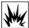
EXPLOSION
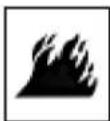
FIRE

ELECTRIC SHOCK

TOXIC FUMES

HOT SURFACE

KICKBACK
! DANGER
Using a generator inside CAN KILL YOU IN MINUTES
Generator exhaust contains carbon monoxide. This is a poison that you cannot see or smell.

NEVER use inside a home or garage, EVEN IF doors and windows are open.
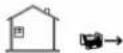
Only us OUTSIDE and far away from windows, doors, and vents
Avoid other generator hazards, READ MANUAL BEFORE USE
! DANGER
Fuel and its vapors are extremely flammable and explosive. Fire or explosion can cause severe burns or death.
WARNING
Running generator emits carbon monoxide: an odorless, colorless, poisonous gas. Breathing carbon monoxide can cause nausea or death!

ONLY operate generators outdoors.
Exhaust gas must be prevented from entering confined areas.
Direct exhaust gas away from windows, doors, ventilation, and other openings.
Do not operate this generator inside or under any buildings.
! WARNING
The engine exhaust from this generator contains chemicals known to the state of California to cause birth defects, reproductive harm, and cancer.
WARNING
Rapid recoil of starter cord (kickback) may pull hand and arm forward toward engine at a rapid rate. Broken bones, bruises, sprains, and fractures may result.
WHEN ADDING OR DRAINING FUEL
- Turn inverter generator off and let it cool for at least three minutes before removing fuel cap. Loosen cap slowly in order to relieve pressure in the fuel tank.
- Fill or drain fuel tank outdoors. Do not excessively inhale fuel vapors.
- Keep away from open flames or sparks and other sources of ignition.
- Do NOT smoke while filling fuel tank.
- Do NOT overfill tank. Allow space for fuel expansion.
WHEN TRANSPORTING OR REPAIRING EQUIPMENT
- Transport inverter generator with the fuel valve in the off position.
- Repair inverter generator with the fuel tank empty or the fuel valve in the off position.
- Disconnect spark plug wire before transport or service.
WHEN STORING FUEL OR EQUIPMENT CONTAINING FUEL
- Store away from furnaces, stoves, water heaters, clothes dryers or other appliances that have pilot light or other ignition source because they can ignite fuel vapors.
WHEN STARTING EQUIPMENT
- Ensure spark plug, muffler, air cleaner, and fuel cap are in place.
- Do NOT crank engine with spark plug removed.
- If fuels spills, wait until it evaporates before starting engine.
WHEN OPERATING EQUIPMENT
- Do NOT choke carburetor to stop engine.
- Do NOT tip engine or equipment at an angle, which causes fuel to spill.


Unintentional sparking can result in fire or electrical shock.
CAUTION!
Improper use and care of this inverter generator will cause damage and shorten its lifespan. Failure to follow these actions will void all warranties.
- Use inverter generator only for appropriate and designated purposes.
- The dealer or customer helpline (1-866-471-7464) can instruct you on intended uses.
- Inverter generator must be placed on a level surface.
- Do NOT expose inverter generator to extreme conditions. Excessive dust, moisture, and corrosive vapors will damage unit.
• Engine cooling slots must be kept clear of debris. - Shut off inverter generator and take to a qualified service center if the unit fails to operate properly.
Automotive Type Electronic Fuel Injection System

This generator has a computer-controlled fuel and ignition system. An on-board computer, referred to in this manual as an ECU (Engine Control Unit) utilizes a series of virtual maps (lookup tables) that provide values for various aspects of engine performance. The ECU analyzes data provided through the various engine sensors to determine the best combination of values from these lookup tables to provide optimum performance. This is communicated to the generator components through the use of digital signals. This is in contrast to non-computer-controlled ignition systems that rely on mechanical feedback, and sometimes vacuum, to control the motion of the various components.
This generator is equipped with an Electronic Fuel Injection (EFI) system, which provides increased efficiency over carbureted fuel systems. In a carbureted fuel system, the fuel and air are mixed in a carburetor that relies on a mechanical choke system controlling the rate of air intake to maintain the vacuum necessary to mix the fuel with air for combustion.
In a fuel injection system, the ECU calculates and adjusts the fuel mixture directly, based on real-time feedback, allowing for greater fuel and emissions efficiency. The ECU also controls the timing for the spark plug, dynamically controlling the speed of the engine depending on requirements for power generation.
When there is a problem reported by a generator component (such as an engine sensor), the ECU stores a fault code for it. These fault codes can be read in the Wattage (P) field of the digital display, and then used to identify the issue and correct it. For more information on fault codes and how to access them, refer to the Fault codes section of this manual. For more information on the digital display and its use, refer to the Digital display section of this manual.
12 LIFAN POWER USA
CONTROLS AND FEATURES

13 LIFAN POWER USA
CONTROLS AND FEATURES
FUEL SWITCH

14 LIFAN POWER USA
CONTROLS AND FEATURES

LIFAN POWER USA
CONTROLS AND FEATURES

16
LIFAN POWER USA
CONTROLS AND FEATURES

17 LIFAN POWER USA
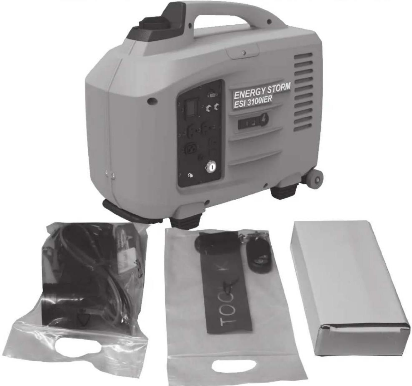
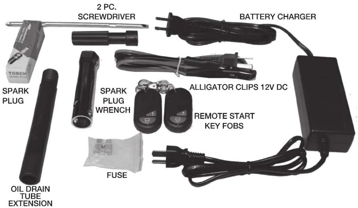
BOX CONTENTS
- Generator
- Accessory Kit
1 x Spark Plug Removal Tool
1 x Oil Drain Tube
1 x 12 Volt Power Cord with Plug & Alligator Clips
1 x Owner's Manual and Warranty Card
PRE-OPERATING INSTRUCTIONS: ASSEMBLY
Your LIFAN Power USA generator is packaged without fuel and oil. Some assembly is required before operating your LIFAN Power USA Generator.
For further assistance in assembling your generator, please visit our website (www.lifanpowerusa.com) or call 1-866-471-7464 between the hours of 9am-5pm Monday-Friday.
UNPACKING THE GENERATOR:
- Set the Carton on a Flat, Rigid Surface.
- Remove All Contents from Carton EXCEPT Inverter Generator.
- Open Box Completely by lifting box cover.
- Carefully lift the Inverter Generator off the remaining box and onto the Flat, Rigid Surface.
AUTO IDLE CONTROL SWITCH
This unit is equipped with an Auto Idle Control feature. The generator will automatically switch to "Gas-Saving" mode when there is no power or load required. Upon demand, the inverter generator will enhance engine speed automatically to provide the correct electrical power the connected device requires. The Auto Idle Control feature minimizes fuel consumption and reduces noise levels.
Turn the AUTO IDLE CONTROL feature "OFF" when:
• High Electrical Loads are connected simultaneously to reduce voltage changes.
- The Equipment connected to the inverter generator requires full power at start-up.
Example: Power Tools and other equipment with electric motors.
- Inverter Generator is working at a constant rated power output
- Your inverter generator will only run at speed required to produce power demanded.
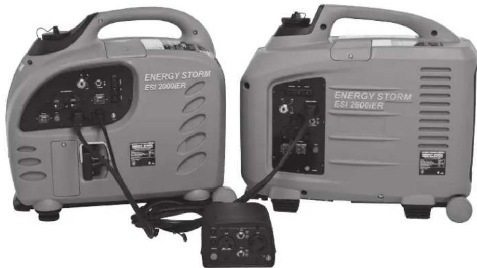
DUO POWER
PARALLEL CONNECTION FEATURE
Both the ESI 2500iER-EFI and ESI 3100iER-EFI come with Parallel connection capability as a Standard feature. With the optional Parallel Connection “Duo Power” Control Box (Part #ESPPC) sold separately, you can Parallel connect 2 Energy Storm Digital Invertors Generators together to achieve the combined wattage of both units. i.e. parallel connect 2-ESI 2500iER-EFI units and achieve 5000 watts, 2-ESI 3100iER-EFI units and achieve 6200 watts or mix and match the ESI 2500iER-EFI and ESI 3100iER-EFI together and achieve 5600 watts.
PRE-OPERATING INSTRUCTIONS: SETUP
CAUTION: Any attempt to start the generator before it has been properly serviced may result in engine failure and void warranty.
ADD ENGINE OIL: Refer to the diagrams below.
- Place generator on level surface.
- Remove the Right Access Panel (Refer to Controls and Features section).
- Clean area around Oil Hole Dipstick/Plug & Unscrew Oil Hole Dipstick/Plug.
- Use Supplied Funnel to Fill with appropriate type and amount of oil using Oil Fill Bottle. Refer to Chart below for recommended oil type based on Environmental temperature.
NOTE: Refer to "Product Specifications" section for universal recommended oil type and oil amount. - Replace Oil Hole Dipstick/Plug and tighten securely.
- Replace the Right Access Panel.

PRE-OPERATING
INSTRUCTIONS: SETUP

WARNING

Fuel and its vapors are extremely flammable and explosive. Fire or explosion can cause severe burns or death.
WHEN ADDING FUEL
- Turn generator off and let it cool for a minimum of three minutes before removing fuel cap.
- Turn and remove cap slowly in order to relieve residual tank pressure.
• Always fill the fuel tank with the unit outdoors. - DO NOT overfill tank. Allow room for fuel expansion.
- Keep fuel away from sparks, open flames, heat, pilot lights, and other ignition sources.
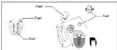
ADD FUEL: Refer to Controls and Features section for diagrams.
- Clean area around fuel cap, then remove fuel cap.
- Pour fresh, clean regular automotive grade unleaded fuel with a minimum octane rating of 85 into fuel tank. Do NOT mix fuel with oil. Fuel must have ethanol blend of 10% or less. Pay close attention to the storage requirements of these fuels. Do
NOT overfill fuel tank.
- Install the fuel cap. Rotate the fuel cap clockwise until it is in its locked position. Wipe away any spilled fuel.
CAUTION: Alcohol-blended fuels (gasohol, ethanol, or methanol) will attract moisture, which leads to separation and formation of acids during storage. Acidic gas can damage the fuel system of an engine while in storage. To avoid engine problems, the fuel system should be treated with a fuel stabilizer or drained if the generator will not be started for thirty (30) days. If using a fuel stabilizer, follow the manufacturer's recommended instructions for use.
NEVER use chemical solvents or cleaners in the fuel tank for damage may occur.
PRE-OPERATING INSTRUCTIONS: SETUP
CAUTION: Any attempt to start the generator before it has been properly serviced may result in engine failure and void warranty.
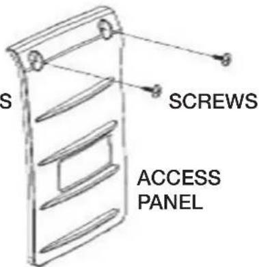
CHECK AIR CLEANER ELEMENT: Refer to diagram below.
- Remove the Left Access Cover (Refer to Controls and Features section).
- Remove the Air Cleaner Case.
- Pull out the Air Cleaner Cartridge, following the direction of the arrow.
- Check the cleanliness of the Air Cleaner Element.
- Clean/Replace if needed.
- Reinstall the Air Cleaner Element.
- Reinstall the Air Cleaner Case.
- Reinstall the Left Access Cover.
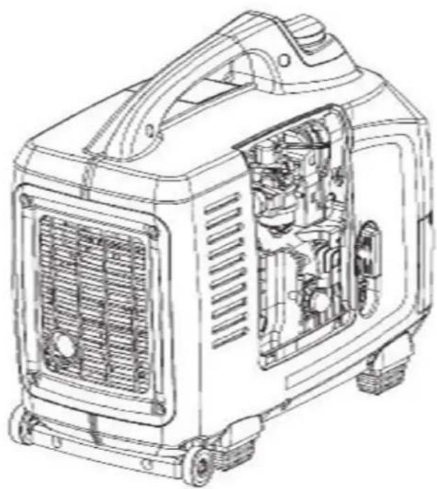

SCREWS
AIR CLEANER CARTRIDGE
AIR CLEANER ELEMENT
PRE-OPERATING INSTRUCTIONS: SETUP
GROUNDING THE GENERATOR: Refer to the diagram below.
- Connect the Ground Terminal on the generator to an acceptable source of electrical ground, such as a copper-grounding stake, using copper electrical wire with a minimum diameter of 16 gauge.

BATTERY ASSEMBLY AND MAINTENANCE:
- Remove Left Access Panel.
- Insert battery into battery tray.
- Install battery cover and tighten clamping nuts.
- Disassemble the setscrew, then connect the wires. The red terminal is anode (+) and the black terminal is cathode (-).
- Reinstall Left Access Panel.

UNDERSTANDING YOUR BATTERY
When the key is turned to the ON position the display illuminates, the ECU turns on, the fuel pump turns on long enough to bring up the fuel pressure, and the stepper motor is energized for proper throttle position for starting. Because of the power requirements of these components, the battery in this generator is considered dead at a higher voltage than it would be in other types of equipment. The battery must have a charge of at least 10.5V to be able to start the generator, even by recoil. If the battery has a charge in the range of 10-10.5V, the generator may crank very well, but the starter will be drawing most of the power, depriving the other components of the power they need to successfully start the generator. There must be a battery charge in excess of 10.5V to ensure that all of the components have the power necessary to start the generator.
During normal use, the generator engine will be shut off with either the remote fob, the ignition key, or by pressing the red STOP button on the control panel. This manual provides instructions, notes, and warnings dealing with each of those methods of stopping the generator. But the
engine may shut off for any of the following reasons:
• The generator may run out of gas.
• The generator may run low on oil.
- The ECU may shut off the engine due to an error reported by a sensor.
These shutdowns may occur when you are not present. When the generator engine shuts off, there will still be a drain on the battery due to the display, the ECU, and the stepper motor, as long as the key is in the ON position. Although the ESI-4000iER-EFI is equipped with a sleep mode that shuts down these components when the generator is not running, the sleep mode circuit will still be monitoring the generator, and over time this circuit will drain the battery below the 10.5V necessary to start the generator. You must turn the key to the OFF position, and turn off the remote switch, to shut off the electronics completely.
UNDERSTANDING YOUR BATTERY
If you are operating the generator through the remote fob and the engine is not running, the remote switch will blink red to remind you to turn the remote switch off. Whenever the remote switch is on, it is drawing current from the battery. When the engine is not running, the battery will not be charged to compensate for the load from the remote receiver, and over time the battery will be drained below the 10.5V necessary to start the generator. You must turn off the remote switch when you will not use the remote fob to start the generator.
If the generator will not start, check the battery voltage with a voltmeter. You can access the battery through the left maintenance door, or you can simply check the voltage through the battery charge receptacle on the control panel. This receptacle is connected directly to the battery, so it can be used without the generator running, or the key in the ON position, or the remote switch on.
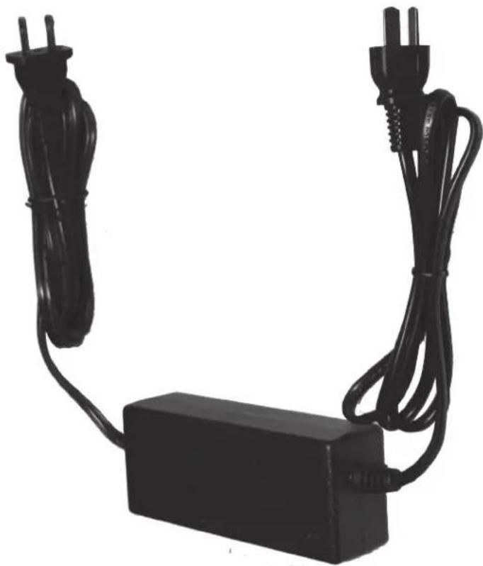
If the battery voltage is below 10.5V, you must charge the battery by connecting the included battery trickle charger to the battery charge receptacle on the control panel (“back-charging”), or directly to the battery leads. Allow the battery to charge fully before attempting to start the generator.
BATTERY ASSEMBLY AND MAINTENANCE:
- Remove Left Access Panel.
- Insert battery into battery tray.
- Install battery cover and tighten clamping nuts.
- Disassemble the setscrew, then connect the wires. The red terminal is anode (+) and the black terminal is cathode (-).
- Reinstall Left Access Panel.

Manual
Find the manual for the Lifan Energy Storm 3100iER-EFI here, totally free. This manual belongs to the generators category and has been rated by 1 users with an average score of 7.8. The manual is currently available in the following languages: English. Do you have a specific question about the Lifan Energy Storm 3100iER-EFI or do you require additional assistance with your product?
Put your question here

Got a question?
Do you have a specific query about the Lifan Energy Storm 3100iER-EFI that the manual doesn't address?
Type your question here ...
Ask a question
√ Receive updates on solutions
√ Get answers to your question
Question and answer
Number of questions: 0
WARNING
- Only operate generator outdoors.
- Prevent exhaust gas from entering, through windows doors or ventilation intakes, any confined areas.
- DO NOT operate generator inside any enclosed or roofed areas. This includes the generator compartment of any recreational vehicle (RV).
- Keep the generator away from other electric cables or wires such as commercial power supply lines.
- The DC receptacle (in the Battery Charge section of the control panel) can be used while the AC power is in use. If you use both at the same time, be sure not to exceed the total power for AC and DC.
- Most appliance motors require more than their rated wattage for start-up.
- It is normal for the run time indicator to have 1-2 hours on the meter from the factory for testing and quality assurance inspections.
- This generator uses a system ground which connects the ground terminals in the AC receptacles on the control panel to the unit frame. The AC neutral wire is not connected to the system ground. If you check the receptacles on this generator with a receptacle tester, the ground circuit condition will appear different than it would for a receptacle in your home.

CAUTION
Never start or shutoff the generator with electrical loads connected and in the operational mode (on switch activated).
- Unplug all electrical loads from the generator.
- Make sure the generator is in a level position.
- Open the Fuel Valve by turning the Fuel Valve to the "ON" position.
28 LIFAN POWER USA
PULL-START (RECOIL) MODELS
Your ESI 3100iER-EFI is Recoil Start.
- Place the ignition switch in the "ON" (I) position using the provided key.
- Grasp starter handle and pull slowly until resistance is felt. Then pull the cord rapidly with a full arm stroke. Allow the rope to return slowly. Do NOT allow the rope to snap back against housing.

REMOTE START MODELS
- Place the remote start switch on the control panel in the "ON" position. CAUTION: Leaving the remote start switch in the "ON" position for more than six hours without operation will result in a dead battery and the inability to start the unit with the key switch or the remote start.
- Double-click and hold the "ON" button (marked with a lightning bolt) on the remote start until the engine starts.
NOTE (all models): If generator does not start within three pulls, check the crankcase oil level. The engine's “Low Oil Shutdown Protection” circuit may be activated and preventing the engine from starting.
NOTE (all models): Unit is equipped with an Automatic Choke.

- Ensure engine is started and Green power Indicator Light illuminates before plugging in any electrical appliance.
- Plug in desired 120 Volt load to the 120 Volt U-Ground receptacles. Always plug appliances into the generator with appliance in its "OFF" position.
- Plug in 12V DC load to the DC receptacle. DC and AC power may be used simultaneously. Circuit Breaker may need to be re-set before using 12V receptacle. When charging 12V batteries insert the charging plug into the DC socket and then connect the terminals to the battery. After charging is complete, remove battery terminal first, then un-plug charging plug from generator. Remove the ground wire of Car Batteries prior to charging and re-connects after charging is complete to avoid short circuit or spark.
- Do NOT connect 240 Volt loads to the 120 Volt receptacles.
- Only connects single-phase 60 Hertz loads.
- DO NOT OVERLOAD THE GENERATOR. FOLLOW THE PROVIDED "GENERATOR WATTAGE REFERENCE WORKSHEET" TO DETERMINE THE RUNNING AND STARTING WATTAGE OF YOUR EQUIPMENT, REFER TO THE PRODUCT SPECIFICATIONS TO ENSURE YOUR GENERATOR WILL OPERATE THE DESIRED EQUIPMENT.

Repeated, substantial overloading that reports an overload condition to the digital display may damage the generator. Marginal overloading that temporarily reports an overload may shorten the service life of the generator.
- Remove all electrical loads from the generator and investigate the cause of the overload.
- Press the (green) overload reset button or reset the circuit protector.
The digital display will remain illuminated and returning data during normal operating conditions.
If the generator is overloaded (in excess of 4000 W), or if there is a short in the connected appliance, the values in the digital display will become zero, the message OVER will appear in the wattage (P) field of the display, and the power output will stop.
OPERATION OF GENERATOR HOW TO USE YOUR GENERATOR

NOTE
Before connecting or reconnecting an appliance to the generator, check that it is in good order, and that its electrical rating does not exceed that of the generator.
This generator has been designed to prevent the engine from "overspeed" revving. Overspeed revving occurs when a generator's on-board monitoring systems detect a drop in voltage from the
inverter, and the generator attempts to compensate by revving the engine higher to generate more electricity. In the rare event of an inverter failure, there will be no voltage output from the inverter, and the engine will remain revving at or close to its top speed. Overspeed revving fora prolonged period can damage internal components due to increased heat from the engine. With an inverter failure, each of the following three symptoms will be present:
- The ECU will draw the engine down to idling speed.
- The digital display will indicate zero (0) Volts.
- The 120 V receptacles will not supply voltage, regardless of breaker settings.
If your generator exhibits this behavior (it only idles, producing no voltage), take the generator to an authorized Lifan Power USA service center for servicing.
NOTE: Use the running and starting wattage provided by the equipment manufacturer if available. If not available, use provided “Generator Wattage Reference Worksheet.”
OUTPUT AND OVERLOAD INDICATOR:
The GREEN Output Indicator Light will illuminate at normal operating conditions.
The RED Output Indicator Light will illuminate when the generator is overloaded, if there is a short circuit in a connected appliance, or if Low Oil Alarm System has been tripped.
OPERATION OF GENERATOR HOW TO USE YOUR GENERATOR
If the RED Output Indicator Light illuminates, STOP the engine and determine the cause of overload by:
- Checking the appliance(s) for proper operation, electrical shorts, and malfunctions. Also ensure the generator has the ability to provide the required starting and running watts of the connected appliance(s).
- Ensuring all appliances is in the "OFF" position upon starting the generator. Only start the connected appliance(s) when the GREEN Output Indicator Light is illuminated and the generator is providing the necessary power to run the connected appliance(s).
Before connecting or reconnecting an appliance to the generator, check that it is in good order, and that its electrical rating does not exceed that of the generator.
LOW OIL ALARM SYSTEM:
This model is equipped with a Low Oil Alert System designed to avoid engine damage from insufficient oil in the crankcase. The Low Oil Alarm System will stop the engine automatically before the oil level in the crankcase drops below safe operating levels. This will cause the RED Output Indicator Light to illuminate. Though the engine will stop running, the ignition switch will remain in the “START” position. Turn to the “STOP” position.
STOPPING THE GENERATOR
Refer to Controls and Features section for diagram.
EMERGENCY SHUTDOWN
- Push the on/off switch to the "off" position.
NORMAL SHUTDOWN
- Unplug all electrical loads or turn the main breaker to the "OFF" position.
- In order to stabilize internal equipment temperatures, allow the engine to run for 3-5 minutes under no load.
- If the generator will not be in use for more than 7 days, turn the fuel valve to the "OFF" position and allow the unit to run until the fuel in the carburetor is used and the engine shuts itself off.
- Turn the ignition switch to the "STOP" position.
- Allow unit to cool to ambient temperature before storage or transportation.
- Always transport the generator with the fuel valve in the "OFF" position. Failure to do so will result in damage to the engine.
REMOTE SHUTDOWN
- Press and hold the "OFF" button (marked with a padlock) on the remote start.
At high altitude, performance will decrease. Engine horsepower will decrease approximately 3.5% for each 1000 feet (305 meters) increase in altitude. At higher altitudes, the density of the atmosphere decreases, so there is less oxygen volume to draw into the cylinder. This means there will be less energy for every power stroke.
STORING THE UNIT
Before long term storage of your power equipment product, typically 30 days or more, perform the following:
- Set the Fuel Valve to the "OFF" position.
- Let the unit continue to run until it stops itself, burning all of the fuel in the fuel system.
- Turn the ignition switch to the "STOP" position.
- Drain the engine oil in accordance with the "Oil Change Procedures" in this Owner's Manual's Maintenance section. Do NOT re-fill with oil until ready to use again.
- Remove the Spark Plug in accordance with the "Spark Plug Maintenance" in the Owner's Manual's Maintenance section. Spray a lubricant, such as WD40®, into the Spark Plug hole to lubricate the top of the piston and walls of the cylinder. Replace the Spark Plug.
- Pull starter rope until resistance is felt. This will place the valves in the closed position.
- Add the recommended amount of fuel stabilizer, in accordance with the amount recommended by the manufacturer of the fuel stabilizer, to the unused gasoline left in the fuel tank.
- Place the unit in a clean, dry, and secure location.
- Cover with "LIFAN Water Proof Generator Cover," Item Number LF100-69600 not included) or canvas/vinyl tarpaulin. Do NOT operate unit with cover installed.
MAINTENANCE
NOTE: Refer to Following Procedures for Proper Method to Perform Maintenance
MAINTENANCE SCHEDULE
| Item | Maintenance Procedure | Regular Service period (1). Perform at every indicated month or operating hour interval, whichever occurs first. | ||||
| Each Use | 1st Month or 4 to 6 Hours | Every 3 Months or 50 Hours | Every 6 Months or 100 Hours | 1x per Year or 300 Hours | ||
| Engine Oil | Check | O | ||||
| Change | O | O | ||||
| Air cleaner | Check | O | ||||
| Clean | O (2) | |||||
| Spark Plug | Clean / Adjust | O | ||||
| Spark Arrester | Clean | O | ||||
| Fuel Filter | Check | O | ||||
| Replace | O (2, 3) | |||||
| Valve clearance | Check / Adjust | O (4) | ||||
| Fuel tank & strainer | Clean | O (2) | ||||
| Fuel line | Check | Every 2-years (Replace as necessary) (3) | ||||
| Battery | Clean / Charge | Charge monthly during long term storage.Check terminals for corrosion monthly, clean as needed.Expected battery life is 2 years, but can be affected by operating environment. | ||||
| Notes:(1) Log hours of operation to determine proper maintenance.(2) Service more frequently when used in dusty areas.(3) This fuel filter allows access to the fuel injector, so maintenance must be done in sanitary conditions. Allowing dust or dirt during maintenance may create problems. After checking or replacing, verify that the fuel filter is not leaking.(4) These items should be serviced by an authorized dealer unless the owner has the proper tools and is mechanically proficient. See the Service Manual. | ||||||
| Service Period for Oil Changes | Normal Operating Temperature |
| Normal –100 hr | 77°F (25°C) |
| 95 hr | 86°F (30°C) |
| 85 hr | 95°F (35°C) |
| 70 hr | 104°F (40°C) |
MAINTENANCE
OIL CHANGE PROCEDURES:
Periodic Maintenance of your engine oil should be performed after each 40 hours of use of you Power Equipment Product. Check your engine oil level prior to each use.
-
Start your engine and let it warm up to get the oil warm and thinner. Turn the ignition switch to the "STOP" position.
-
Remove the Right Access Cover.
-
Remove the oil cap/dipstick by turning counter clockwise. USE CAUTION: THE OIL MAY BE HOT.
-
Drain the engine oil using the provided Oil Drain Tube Extension by screwing the tube extension onto the oil fill socket. Tip the unit to the oil drain side to drain the used oil into an approved receptacle and discard in accordance with all Federal and State Regulations. Never dump the used engine oil on the ground or into drains, only discard in an approved manner. Check with your local authorities to determine the regulations in your area.
WARNING! AVOID SPLASHING OF HOT OIL; IT CAN BURN YOU AND CAUSE SEVERE INJURY.
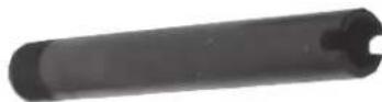

-
After oil is completely drained, replace dipstick plug and tighten with appropriate tools. Replace oil with the proper oil for your product. Refer to the Pre- Operating Instruction: Generator Setup section for exact fill requirements. Always use your dipstick to check the oil level and only fill to the full mark on the dipstick. Never overfill the engine as this can cause damage to the unit and void warranty.
-
Replace the dipstick/oil cap on the engine.
-
Replace Right Access Cover.
-
Shake generator to ensure the float in the Oil Alert System is free.
PROPER MAINTENANCE OF THE UNIT WILL INCREASE THE LIFE OF YOUR PRODUCT. THE OIL MUST BE CHANGED ON A REGULAR BASIS FOR PROPER OPERATION, AND RELIABILITY AND TO ALSO MAINTAIN THE WARRANTY ON THIS PRODUCT.
MAINTENANCE
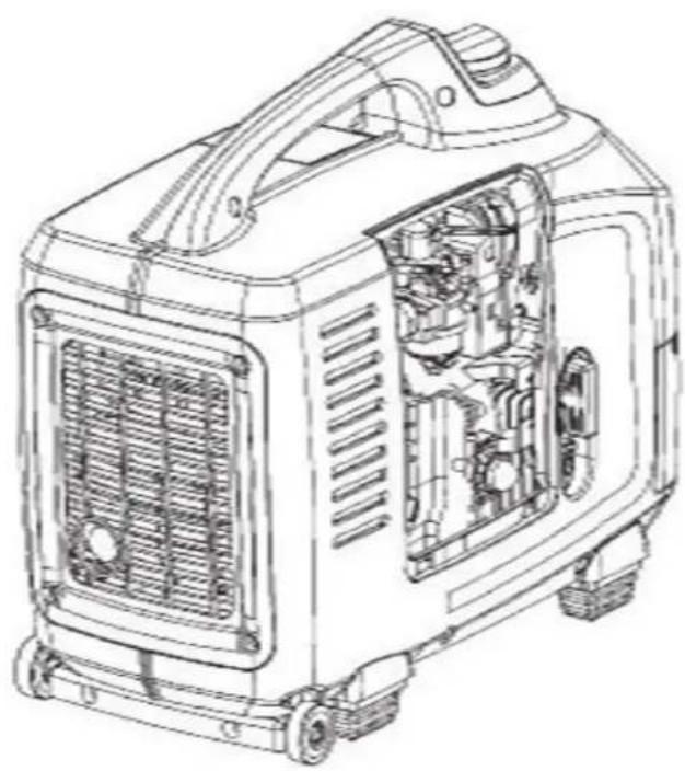
AIR CLEANER MAINTENANCE:
Refer to Controls and Features section for diagram.
- Remove Left Access Cover.
- Remove the Air Cover Case.
- Pull out the Air Cleaner cartridge following the direction of the arrow.
- Check the Air Cleaner Element for cleanliness. If needed clean/replace Air Cleaner Element.
- Reinstall Air Cleaner Element and Cartridge.
- Reinstall Air Cover Case.
- Reinstall the Left Access Cover.
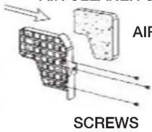
AIR CLEANER CARTRIDGE
AIR CLEANER ELEMENT

MAINTENANCE

SPARK PLUG MAINTENANCE
Recommended spark plug: F7RTC
To ensure proper engine operation, the spark plug must be properly gapped and free of deposits.
- Loosen the cover screws and remove the maintenance door.
- Remove the spark plug cap.
- Clean any dirt from around the spark plug base.
- Use the supplied wrench to remove the spark plug.
- Visually inspect the spark plug. Discard it if the insulator is cracked or chipped.
- Clean the spark plug with a wire brush if it is to be reused.
- Measure the plug gap with a feeler gauge. The gap should be 0.028-0.031 in (0.7-0.8mm).
- Correct as necessary by carefully bending the side electrode.
FUEL SYSTEM MAINTENANCE:
Refer to Controls and Features section for diagram. NOTE: Periodically you can get sediment or trash in your Carburetor Bowl. Use the following procedures to clean:
- Turn the fuel valve to the "OFF" Position.
- Remove the Left Access Panel.
- Remove the carburetor bowl by removing the mounting bolt located at the bottom of the bowl.
- Dump out the old fuel and sediment into an approved container and clean carburetor bowl thoroughly.
- Fit a new rubber washer into place and re-attach fuel bowl to the carburetor.
NOTE: Removal of the drain screw at the bottom of the bowl can drain the fuel to remove smaller debris that has collected in the bowl.
-
After bowl is securely back in place, turn the fuel Valve to the "ON" position for use.
-
Units equipped with a pre-filter for fuel will have a filter housed just below the fuel cock. Remove the fuel filter element (refer to "Fuel Filter Element Removal")
37 LIFAN POWER USA
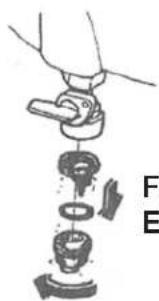
Fuel Filter Element Removal
MAINTENANCE
If the generator has been running, the muffler will be very hot. Allow it to cool before proceeding.
Fuel Filter Element Assembly
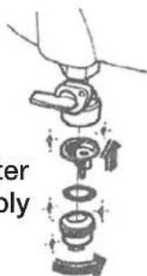
Spark Arrestor Maintenance
- The spark arrester must be serviced every 100 hours to maintain its efficiency, or a decrease in Horsepower may occur.
-
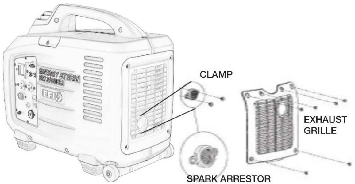
Because of the size of the spark arrester opening in the exhaust grille you may decide that you do not want to take off the grille. This will not cause an issue unless you drop the arrester or the clamp or screws behind the grille. Taking the grille off or leaving it on is a matter of your convenience, but the procedure below will include removing the grille.
-
Remove the exhaust grille to access the spark arrestor.
- Remove the screws holding the clamp and the spark arrester to the muffler.
- Clean the spark arrestor with a stiff wire brush.
- Replace if the wire mesh is perforated or torn.
- Reinstall the spark arrester and the clamp.
- Reinstall the exhaust grille.
TRANSPORTING THE GENERATOR
To prevent fuel spillage when transporting or during temporary storage, the generator should be secured upright in its normal operating position with the ignition switch "OFF" and turn the fuel cap vent to off position.

When transporting the generator:
- Do not operate the generator while it is on or in a vehicle.
- If you must transport the generator in an enclosed vehicle, drain all fuel from the generator.
During short term storage, the generator should be secured upright in its normal operating position with the on/off switch turned "OFF".
Avoid placing the generator in direct sunlight when storing.
If the generator is left in an enclosed area or vehicle, high temperatures inside could cause residual fuel to vaporize resulting in possible explosion.
LONG-TERM STORAGE OF THE GENERATOR
During long term storage, the generator should be secured upright in its normal operating position with the switch turned "OFF".
Avoid placing the generator in direct sunlight when storing.

- If the generator is left in an enclosed area or vehicle, high temperatures inside could cause residual fuel to vaporize resulting in possible explosion.
- Gasoline is extremely flammable and explosive under certain conditions.
WARNING
- Do not smoke or allow flames or sparks in the area.
- During long-term storage, or infrequent use of your equipment, it is important to add a fuel stabilizer, such as STA-BIL® Fuel Stabilizer, to help prevent fuel oxidation (breakdown) and the formation of gum and varnish, and to inhibit corrosion in the fuel system.
LONG-TERM STORAGE OF THE GENERATOR
-
Be sure the storage area is free of excessive humidity and dust, and out of direct sunlight.
-
It is best to keep the tank at least 95 % full, as condensation will be less likely to occur in the fuel tank during storage if the tank is full. Do not overfill the tank, as the fuel will need room to expand on hot days. Add an appropriate amount of fuel stabilizer (per the instructions on the bottle) and run the generator for 5 minutes to ensure that any fuel trapped in the system has the stabilizer in it. You may also opt to add the fuel stabilizer and run the unit until it is out of fuel.
If you opt to drain the fuel, then continue on with the instructions below.
-
To drain the gasoline from the fuel tank, turn the ignition switch to the "OFF" position.
-
Siphon the fuel from the tank.
-
Change the engine oil.
-
Remove the spark plug and pour about a tablespoon of clean engine oil into the cylinder.
-
Crank the engine several revolutions to distribute the oil and then reinstall the spark plug.
-
Slowly pull the starter grip until resistance is felt. At this point, the piston is coming up on its compression stroke and both the intake and exhaust valves are closed. Storing the engine in this position will help to protect it from internal corrosion.
-
Turn the remote switch to the "OFF" position to prevent unwanted, unintentional cranking and excessive battery drain.
-
Once a month, recharge the battery.
SHORT-TERM STORAGE
For Short Term storage of your power equipment product, typically 30 days or more, perform the following:
During short term storage, the generator should be secured upright in its normal operating position with the switch turned "OFF".
Avoid placing the generator in direct sunlight when storing.

WARNING
- If the generator is left in an enclosed area or vehicle, high temperatures inside could cause residual fuel to vaporize resulting in possible explosion.
- Place the unit in a clean, dry, and secure location.
- Cover with "LIFAN Water Proof Generator Cover," Item Number LF100-69600 not included) or canvas/vinyl tarpaulin. Do NOT operate unit with cover installed.
EXERCISING THE GENERATOR
It is essential that the generator be exercised on a regular basis. This will prevent the accumulation of varnish or sludge in the fuel system; remove moisture from the generator windings and help keep the battery properly charged. Additionally, the engine seals and moving components will be lubricated. Exercise the generator by running it with at least a 1/2 load (1800W) for 15 minutes per month. Gasoline fuel treatments (such as STA-BIL®) to prevent contamination of your fuel supply are available from your dealer.

NOTE: Fuel varnishing necessitating replacement of the fuel injector is not a warrantable failure.
TROUBLESHOOTING
IF THE ENGINE WILL NOT START:
- Check to ensure switches are in the "ON" position.
- Check engine oil level. Your unit possesses a Low Oil Alarm System that will not allow your engine to start if the oil is below safe operating levels. This feature is installed to increase the life of your engine and prevent engine damage. If oil level is low, fill to the full mark on dipstick. Refer to the Product Specifications for exact oil type and amounts.
- Add fuel stabilizer. Turn fuel shut-off valve to "off" position, run unit until fuel in fuel lines and carburetor has burned out of system.
- Check the fuel level to insure adequate fuel. Add fuel if necessary.
- Remove and inspect the spark plug for cleanliness and proper electrode gap. If needed, clean or replace the spark plug. Refer to Spark Plug Maintenance in the Maintenance section of the Owner's Manual for proper procedure.
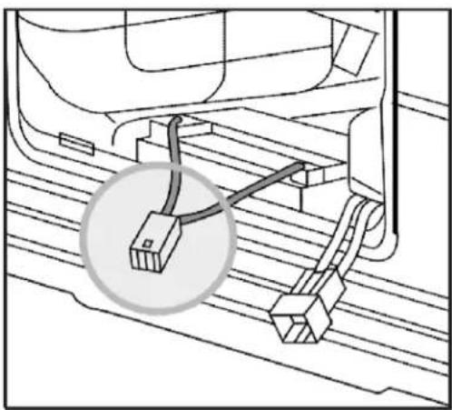
NOTE: Periodically on the initial start-up or after the unit has been stored for a long period of time, the float for the “Low Oil Alarm System” will stick to the bottom of your oil pan. Locate the two (2) wires to the Low Oil Sensor Diode (refer to figure on the right) located on the side of the engine block. Unplug these wires and, only after ensuring the engine is full of oil, start the engine and allow to run until warm (normally 20 minutes, as this will heat the oil and release the float on the Low Oil Alert System). Then re-plug the wires to the terminals on the Low Oil Alarm Sending Unit.

UNIT DOES NOT PROVIDE ELECTRICAL CURRENT:
- Plug in a small appliance or tool to test.
- Check if the AC (or DC) Circuit Breaker is in the "ON" position. If not, place in "ON" position.
- If your unit still does NOT produce electricity after performing the previous checks, call LIFAN Power USA at 1-866-471-7464, your dealer, or authorized Service Center.
AC APPLICATION
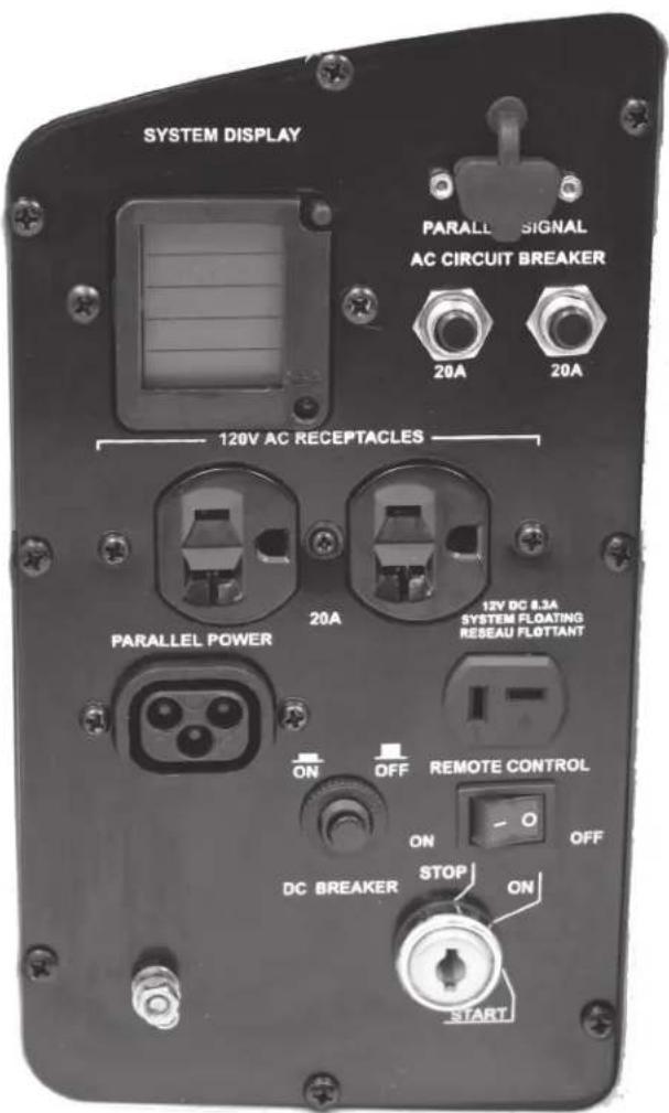
The control panel has two AC breakers: Two (2) 20 A breakers for the 5-20R split duplex receptacle. The 20A breakers each protect one of the circuits in the 5-20R split duplex receptacle; the left 20A breaker protects the top receptacle, and the right 20A breaker protects the bottom receptacle.
Ensure that the breaker is on for the receptacle you want to use.
- Start the engine.
- Make sure the digital display is illuminated and returning data.
- Confirm that the appliance to be used is switched off before plugging into the control panel.
- Plug the appliance into the control panel.
LOW OIL ALARM SYSTEM
The low oil alarm system is designed to prevent engine damage caused by an insufficient amount of oil in the crankcase. Before the oil level in the crankcase falls below a safe limit, the low oil alarm system will automatically shut down the engine (the ignition switch will remain in the “ON” position).
If the low oil sensor shuts down the engine, the low oil light (red) will come on when you operate the starter, and the engine will not run. If this occurs, add enough of the approved engine oil to raise the level to the top line on the dipstick.
POWERING 12V DC DEVICES
This generator can be used to power 12V DC devices through the DC receptacle on the control panel while the generator is running. The DC output comes directly from the battery, so powering a DC device places a load on the battery. The DC device should require no more than 12V or draw more than 10A (which is the size of the DC breaker). The voltage regulator recharging the internal battery is designed for a maximum charge amperage of 11-12A, so as long as the generator is running the internal battery should not be drained.

NOTE
- The generator does not have to be running to power a DC device, but if the generator is not running the battery will be drained, and you may have to recharge the battery before you can start the generator again.
Back-charging the generator battery
This generator battery can be back-charged through the DC receptacle by the included battery trickle charger). The generator does not have to be running to back-charge the battery, and there are no special considerations for switches to be on or off for the battery to charge, though if the generator is not running, the remote switch should be in the “OFF” position.

NOTE
- The ECU and fuel pump require the battery to retain some charge, or the generator can't be started, even by recoil. It may be necessary to charge the battery before the generator can be started at all.
- Connect the polarized connector of the battery charger to the DC receptacle.
- Charge the battery for 3 hours. If you are using the included Plug-In Trickle Charger, charge the battery until the status indicator goes from red to green.
JUMP-STARTING THE GENERATOR
This generator was not designed to be jump-started through the DC receptacle and it is not recommended to do so. If you connect an external battery to the DC receptacle before the generator is started and attempt to start the generator with the key fob or the ignition switch, a jump-start may occur, but it will likely trip the DC breaker. It is recommended to connect external batteries to the DC receptacle using the procedure given in Charging External Batteries. If however, you do trip the DC breaker, press the breaker reset button located next to the DC receptacle on the control panel.
ENGINE WILL NOT START
![graph TD A["Does the generator's internal battery have a charge of at least 10.5V?"] -->|NO| B["Charge the internal battery to at least 10.5V."] A -->|YES| C["Is the battery fuse missing or burned out?"] C -->|YES| D["Replace the fuse."] C -->|NO| E["Check all connections between the battery, contro…](/content/2026/05/1059924/images/5b4d7e714990d51e562d6d7f3e653753f4ec6f1affcc075ac6a088bece679f8b.jpg)
Engine will not crank with the key or remote start
![graph TD A["Does the battery have a full charge?*"] -->|YES| B["Is there enough oil in the engine?"] A -->|NO| C["Fully charge the battery"] B -->|YES| D["Is there a spark from the spark plug?"] B -->|NO| E["Add the recommended oil"] D -->|NO| F["Replace the spark plug."] E -->|No| G["Take the gener…](/content/2026/05/1059924/images/d8c96b72a0e8f3549437c7e1c38e7a90a67bc8d6078b5df8dcc1a8ed2c5260de.jpg)
NO OUTPUT AT THE DC RECEPTACLE
![graph TD A["Is the DC circuit breaker tripped?"] -->|YES| B["Reset the circuit breaker."] A -->|NO| C["Take the generator to an authorized Lifan Power USA service center."]](/content/2026/05/1059924/images/001369101c70e59786010f64a80b174bcf68a533e79a4bb580ee38efda9c0c1d.jpg)
DIGITAL DISPLAY
This generator is equipped with an LCD digital display that provides continuously-updated status information for the following parameters:
• (U) Voltage—Current voltage supplied
• (I) Amperage for the generator output
• (P) Wattage (power) output for the generator
• (T) Run time—Total generator run time since first start (in hours)
• (FUEL) Fuel level (bar reading)

NOTE
- It is normal for the run time indicator to have 1-2 hours on the meter from the factory for testing and quality assurance inspections. Within a few seconds of illumination, the display will begin to show new data, and at that point the generator is ready to supply power.

ERROR - FAULT CODES DIGITAL READ-OUT
The low oil alarm system is designed to prevent engine damage caused by an insufficient amount of oil in the crankcase. Before the oil level in the crankcase falls below a safe limit, the low oil alarm system will automatically shut down the engine (the ignition switch will remain in the “ON” position).
| PARTS ERROR CODE FAULT DESCRIPTION SOLUTION TO ISSUE | |||
| Injector | P0261 No voltage to injector | Replace fuel injector or wiring harness | |
| P0262 Check connection to injector | Replace fuel injector or wiring harness to injector | ||
| Manifold Air Pressure Sensor | P0107 Short circuit Replace MAP sensor | ||
| P0108 Signal line break Replace MAP sensor | |||
| Oxygen Sensor | P0130 Signal line break Replace oxygen sensor | ||
| P0131 Short circuit Replace oxygen sensor | |||
| P0132 Short circuit Replace oxygen sensor | |||
| Fuel Pump Relay | P0230 Relay shorted | Replace fuel pump relay or fuel pump | |
| Temperature Sensor | P0117 Short circuit Replace temperature sensor | ||
| P0118 Signal line break Replace temperature sensor | |||
| Step Motor | P0505 Signal line break Replace step motor | ||
WATTAGE CHART
| RUNNINGWATTAGE REQUIREMENTS | ADDITIONAL STARTING WATTAGE REQUIREMENTS | |
| HEATING/COOLING: | ||
| Furnace Fan, gasor fuel oil furnace | ||
| 1/8 horsepower | 300 | 500 |
| 1/6 horsepower | 500 | 750 |
| 1/4 horsepower | 600 | 1000 |
| 2/5 horsepower | 700 | 1400 |
| 3/5 horsepower | 875 | 2350 |
| Central Air Conditioner | ||
| 10,000 BTU | 1500 | 2200 |
| 20,000 BTU | 2500 | 3300 |
| 24,000 BTU | 3800 | 4950 |
| 32,000 BTU | 5000 | 6500 |
| 40,000 BTU | 6000 | 6700 |
| HEATING/COOLING: | SUB-TOTAL: | |
| KITCHEN | ||
| Refrigerator, Average | 600 | 2200 |
| Dish Washer - Cool Dry | 700 | 1400 |
| Dish Washer - Hot Dry | 1450 | 1400 |
| Clothes Dryer - Gas | 700 | 1800 |
| Clothes Dryer - Electric | 5750 | 1800 |
| Microwave Oven, 750W | 750 | 800 |
LIFAN POWER USA
WATTAGE CHART
| Washing Machine | 750 | 2300 |
| Coffee Maker | 850 | 0 |
| Toaster 2-slice | 1100 | 0 |
| Toaster 4-slice | 1650 | 0 |
| Electric Skillet | 1500 | 0 |
| Electric Range 6-in. element | 1500 | 0 |
| Electric Range 8-in. element | 2100 | 0 |
| KITCHEN | SUB-TOTAL: | |
| APPLIANCES | ||
| Lights- Wattage | Actual: | |
| VCR | 50 | 0 |
| Heating Pad | 65 | 0 |
| Radio | 100 | 0 |
| Television - Black & White | 100 | 0 |
| Television - Color | 300 | 0 |
| Dehumidifier | 400 | 0 |
| Electric Blanket | 400 | 0 |
| Garage Door Opener - 1/4HP | 550 | 1100 |
| Garage Door Opener - 1/3HP | 725 | 1400 |
| Well Pump - 1/3 hp | 750 | 1400 |
| Well Pump - 1/2 hp | 1000 | 2100 |
| Sump Pump - 1/3 hp | 800 | 1300 |
| Sump Pump - 1/2 hp | 1050 | 2150 |
| Vacuum Cleaner - Standard | 800 | 0 |
| Vacuum Cleaner - Deluxe | 1100 | 0 |
WATTAGE CHART
| APPLIANCES | SUB-TOTAL: | |
| COMMERCIAL PRODUCTS: | ||
| Jigsaw | 300 | 300 |
| Electric Weed Trimmer | 500 | 500 |
| Router | 1000 | 1000 |
| Belt Sander | 1000 | 1000 |
| Disc Sander | 1200 | 1200 |
| Chain Saw | 1200 | 1200 |
| Worm Drive Saw | 1560 | 3100 |
| 12" Concrete Cutter | 1800 | 3600 |
| 7 1/4" Circular Saw | 1500 | 3000 |
| Disc Grinder | 2000 | 4000 |
| Air Compressor, Average | 2000 | 4000 |
| COMMERCIAL PRODUCTS: | SUB-TOTAL: |
CONVERTING AMPS OR HORSEPOWER INTO WATTS
If necessary, use these formulas:
Watts = Amps x Volts
Running Watts* = Horsepower x 932** (for motors)
Remember, this worksheet lists average power requirements a particular manufacturer's device may use more or less than the listed wattage.
- Add a 10% correction factor to your totals to help overcome this uncertainty. If your customer plans to operate devices that use electric motors, list both the starting and running requirements of each.
- Starting requirements of some devices maybe significantly higher than their running requirements. This higher demand must be considered when estimating your power needs. Some small, universal motors — which do not draw a heavy starting load (drills, small saws, blenders, etc.) — require very little extra current for starting.
When listing items that use motors, take them in the order of highest-to-lowest starting requirements, as shown in the example below. Motor A, for instance, has a starting requirement of 2,600 watts, so it's listed first, followed by Motor B at 1,300 watts, and Motor C at 1,000 watts.
| MOTOR/DEVICE | STARTINGWATTS | RUNNINGWATTS |
| Motor A | 2,600 | 850 |
| Motor B | 1,300 | 600 |
| Motor C | 1,000 | 750 |
NO ELECTRIC MOTORS
If your list does not include any devices that use electric motors, simply add the power (running) requirements of all the items on your list to obtain the maximum power needed.
For example, if you intend to use only an electric skillet, a 100-watt light and a heating pad (as shown below), the maximum power requirement would be 1,655 watts. In this case, a generator like the EF2600, that can produce 2,300 watts rated output, is recommended.
LIMITED WARRANTY POLICY
This warranty is limited to the following Lifan Power and Storm Series products that are distributed by the EquipSource LLC, d/b/a LIFAN POWER USA, located at 2205 Industrial Park Road, Van Buren, AR 72956. Effective date is 4/20/2010.
LENGTH OF WARRANTY
Residential Use** Commercial/Rental**
| PRODUCTS COVERED | 1st Year 2nd Year 3rd Year | Warranty not to exceed 300 hrs. or terms listed below. | ||
| Walk Behind Mowers | Full unit parts and labor | Full unit parts only | Engine: parts only | Full unit: 3 months parts and labor |
| Water Pumps | Full unit parts and labor | Full unit parts only | Engine: parts only | Full unit: 12 months parts and labor |
| Generators/Inverter Generators | Full unit parts and labor | Full unit parts only Engine: | parts only Full unit: 12 | months parts and labor |
| Pressure Washer Engines | Full unit parts and labor | Full unit parts only | Engine: parts only | Full unit: 12 months parts and labor |
| Pressure Washer Pumps* | Full unit parts and labor | NA | NA | Full unit: 12 months parts and labor |
| Gasoline Engines | Full unit parts and labor | Full unit parts only | Engine: parts only | Full unit: 12 months parts and labor |
| Gasoline Powered Welders | Full unit parts and labor | Full unit parts only | Engine: parts only | Full unit: 6 months parts and labor |
*All Lifan Pressure Pro™ and Storm Series Pressure Storm™ pressure washers are equipped with Annovi Reverberi ™ high pressure water pumps which are covered by the manufacturer's 1 year limited warranty. Go to www.lifanpowerusa.com for details.
** Residential Use is defined as items that are for personal use.
*** Commercial/Rental use is defined as any usage for income producing or other business related uses.
In order to qualify for the limited warranty the product(s) must be purchased in North America from an authorized Equip-Source, LLF d/b/a Lifan Power USA dealer or a dealer authorized by EquipSource to sell Lifan products. This warranty is non-transferable and applies only to the original purchaser. The supplied “Warranty Registration Card” must be completed and on file with American Warranty Service (at the supplied address), at the time that any warranty claim is made. The “Warranty Registration Card” must be submitted with a receipt of purchase which clearly states the date of purchase and where the purchase was made.
During the warranty period (stated above) Equipsource, LLC and/or American Warranty Service will repair or replace, at its' option, any part that is proven to be defective in material or workmanship under normal usage. Repairs and/or replacement will be made without charge for parts or labor. All parts found to be defective must be returned to Equip-Source or American Warranty Service at our direction. Upon reception of the parts a judgment as to the validity of the warranty claim will be determined. All parts replaced under warranty or any replacement of the complete unit will be considered part of the original product and replacement of any product, and any warranty on those parts or replacement unit will coincide with the original warranty.
To obtain Warranty Service, call our Customer Service Hotline at 1-866-471-7464 and press 2 for Warranty Service at which time you will be transferred to the technicians at American Warranty Service. In lieu of this you may call directly to American Warranty Service at 866-926-4313 to be directly connected to a repair specialist. If your issue cannot be resolved through consultation with our customer service representatives, you will be directed to an Independent Service Center of your choice nearest your location. Any manufacture's Defects of your product will be repaired or replaced at no charge to you per our commitment. If the issue with your unit is not a Manufacture's Defect, you will be advised to make payment to the Service Center upon diagnosis of repairs which are not covered under the Manufacturer's Warranty Policy. In this case the end user is responsible for all shipping and handling charges associated with the exchange and as stated above the warranty will coincide with the date of the original purchased unit.
LIMITED WARRANTY POLICY
This warranty is not valid for products or parts affected or damaged by accident, collision, normal wear, fuel contamination, abuse, neglect, misuse, alteration and/or unsuitable use or unauthorized parts replacement. Mower decks and blades are specifically not warranted for impact or abrasive damage. Warranty becomes void if the customer fails to install, maintain, and/or operate the product in accordance with the instructions and recommended actions of Lifan set forth in the owner's manual. EquipSource, LLC disclaims any responsibility for time loss or loss of usage of the product, transportation, commercial loss, or any other incidental or consequential damage. Prior to any warranty service an approval code must be issued to the service center in order for the warranty claim to be valid. Any implied warranties are limited to the duration of this written limited warranty. This warranty gives you specific legal rights, and you may also have other rights, which may vary from state to state.
OWNER'S RESPONSIBILITY
To ensure trouble free warranty coverage it is important that you register your Lifan generator by phone at 1-866-471-7464, or by filling out and returning to Lifan Power USA the warranty registration card supplied with your generator.
REGISTERING YOUR PRODUCT
This confirms your warranty coverage and provides a direct link between you and Lifan Power USA if we find it necessary to contact you. Your receipt for purchase including date, model and serial number must be maintained and registered to receive service from an Authorized Service Dealer for warranty service. Proof of purchase rests solely with you, the original purchaser. You must demonstrate reasonable care and use, and follow preventive maintenance, storage, fuel and oil usage as prescribed in the operator's manual for your Lifan Power unit. For the warranty assistance from a Lifan Authorized Service Dealer nearest to you, call Lifan's automated phone at 1-866-471-4764 Option 2. Should you require assistance or have questions concerning Lifan Power USA Warranty Statement, you can contact us through the web at www.lifanpowerusa.com or call toll free 1-866-471-7464.
EXCLUSIONS
- Lifan Power Equipment that utilize non-Lifan replacement parts.
- Failure to perform "Periodic Maintenance" as required and specified in the supplied "Owner's Manual."
• Costs of normal maintenance and adjustments. - Failures caused by any contaminated fuels, oils, or lack of proper oil levels.
- Repairs or diagnostics performed by individuals other than Lifan authorized dealers not authorized in writing by Lifan.
- Failures due to normal wear and tear, accident, misuse, abuse, negligence or improper use.
- As with all mechanical devices, the Lifan engines need periodic part(s) service and replacement to perform as designed. This warranty will not cover repair when normal use has exhausted the life of a part(s) or engine.
- Failures caused by any external cause or act of God, including but not limited to, collision, theft, vandalism, riot, war, fire, freezing, lightning, earth-quake, windstorm, hail, water, flood, tornado, or hurricane or any occurrence outside of normal use and activity.
- Damage related to any animal infestation to include rodent and/or insect infestation.
- Products that are modified or altered in a manner not authorized in writing by Lifan.
- Any incidental, consequential or indirect damages caused by defects in materials or workmanship, or any delay in repair or replacement of the defective part(s).
- Failure due to misapplication.
- Telephone, cellular phone, facsimile, internet access, or other communication expenses.
- Expenses related to "customer instruction" or troubleshooting where no manufacturing defect is found.
• Overnight freight or special shipping costs for replacement part(s).
• Overtime, holiday or emergency labor. - Starting batteries, fuses, light bulbs and engine fluids.
- SPECIAL RESTRICTION ON ALL RESIDENTIAL GRADE EQUIPMENT: Any residential grade unit used in a commercial application falls under a 60-day limited warranty.
LIMITED WARRANTY POLICY
DISCLAIMER OF IMPLIED WARRANTIES
This limited warranty is in lieu of all other expressed or implied warranties, including any warranty of the unit's fitness for any particular use and any implied warranty of MERCHANTABILITY otherwise applicable to Lifan Power Equipment and its affiliated companies shall not be liable for any special, incidental or consequential damage, including lost profits. There are no warranties extended other than as provided herein. This limited warranty may be modified only by Lifan Power USA. Any implied warranties allowed by law shall be limited in duration to the terms of the express warranty provided herein. Some states do not allow limitations on how long an implied warranty lasts, so the above limitation may not apply to you. Some states do not allow the exclusion or limitation of incidental or consequential damages, so the above limitation may not apply to you. This warranty gives you specific legal rights. You also have other rights from state to state. Lifan's ONLY LIABILITY SHALL BE THE REPAIR OR REPLACEMENT AS STATED ABOVE. IN NO EVENT SHALL Lifan BE LIABLE FOR ANY INCIDENTAL OR CONSEQUENTIAL DAMAGES, EVEN IF SUCH DAMAGES ARE A DIRECT RESULT OF Lifan's NEGLIGENCE. Some states do not allow the exclusion or limitation of incidental or consequential damages, so the above limitation may not apply to you. This warranty gives you specific legal rights and you may also have other rights from state to state.
GOVERNING LAW/ CONSENT TO JURISDICTION AND FORUM SELECTION
The laws of the State of Arkansas shall govern the rights and duties of the parties under this agreement and jurisdiction and venue is fixed in Crawford County, Arkansas. The buyer/owner hereby waives any right it may have to assert the doctrine of forum non conveniens or similar doctrine or to object to venue with respect to any proceeding brought in accordance with this paragraph, and stipulates that the State and Federal courts located in the County of Crawford, State of Arkansas shall have in person jurisdiction and venue over each of them for the purpose of litigating any dispute, controversy, or proceeding arising out of or related to the sale, manufacture or warranty of products with EquipSource, LLC.
OWNER'S WARRANTY RESPONSIBILITIES
As the outdoor equipment owner, you are responsible for performance of the required maintenance listed in your owner's manual. EquipSource, LLC d/b/a Lifan Power USA recommends that you retain all receipts covering maintenance on your outdoor equipment. Lifan Power USA will not deny your warranty coverage based solely on your lack of receipts for service however, the condition of the equipment upon arrival at the service center will determine the warrantable nature of the product.
As the outdoor equipment owner, you should however be aware that Lifan Power USA may deny your warranty coverage if your outdoor equipment or a part has failed due to abuse, neglect, or improper maintenance or unapproved modifications.
If you have any questions regarding your warranty rights and responsibilities, you should contact Lifan Power USA or American Warranty Service Representative at 1-866-471-7464 Option 2 Warranty and Service or at the following address Lifan Power USA, 2205 Industrial Park Road, Van Buren, AR 72956 or by contacting us through www.lifanpowerusa.com.
This warranty specifically excludes the use of any Lifan Power Equipment or Storm Series power equipment as the "Sole Source of Power" for "off the power grid applications" and this warranty will become null and void for units used for this purpose and manner. This warranty specifically excludes the use of any Lifan Power Equipment or Storm Series power equipment for the purpose of powering Life Support devices, Life Support appliances, Medical devices, and/or Medical appliances.
EquipSource, LLC will not be held responsible for any damage due to the use of any Lifan or Storm Series power equipment for these purposes.

APPENDIX:
EXPLODED VIEW & PARTS LIST
54
[NO TEXT]
LIFAN POWER USA

LIFAN POWER USA

| S/N | Part No. | Description | Qty |
| 1 | 7502 | 157F Engine | 1 |
| 2 | 09010337 | Muffler gasket | 1 |
| 3 | 03050211 | Bolt | 2 |
| 4 | 03071421 | Sensor support | 1 |
| 5 | 03050221 | Bolt | 2 |
| 6 | 01150204 | Ignition Sensor | 1 |
| 7 | 030503897 | Screw | 2 |
| 8 | 60024 | Stator | 1 |
| 9 | 03050211 | Bolt | 2 |
| 10 | 092601004 | Flywheel | 1 |
| 11 | 03060118 | Nut | 1 |
| 12 | 6868845 | Flywheel fan | 1 |
| 13 | 09010340 | Clutch | 1 |
| 14 | 03050221 | Bolt | 2 |
| 15 | 09020246 | High voltage wire rubber sheath | 1 |
| 16 | 09010347 | Engine fan cover | 1 |
| 17 | mutual-inductor support | 1 | |
| 18 | 63053 | mutual-inductor module | 1 |
| 19 | 03050201 | Bolt | 2 |
| 20 | 03050201 | Bolt | 3 |
| 21 | 09010341 | Recoil starter | 1 |
| 22 | 03050221 | Bolt | 3 |
| 23 | 03050339 | Screw | 1 |
| 24 | 09040223 | Recoil starter baffle | 1 |
| 25 | 71010 | Inverter assembly | 1 |
| 26 | 09070172 | Battery | 1 |
| 27 | 09070329 | Battery Hold Down Bracket | 1 |
| 28 | 04170302 | Ignition coil shealth Insulator | 1 |
| 29 | 03050223 | Bolt | 2 |
| 30 | 080119003 | Ignition coil | 1 |
| 31 | 090705022 | ECU | 1 |
| 32 | 092101067 | Hose Clamp | 1 |
| 33 | 090705013 | Fuel injector inlet upper Fuel Line | 1 |
| 34 | 092101067 | Hose Clamp | 1 |
| 35 | 09010162 | Fuel filter Cannister | 1 |
| 35-1 | Fuel Filter Cartridge | 1 | |
| 36 | 092101067 | Hose Clamp | 1 |
| 37 | 090705013 | Lower Fuel Line | 1 |
| S/N | Part No. | Description | Qty |
| 38 | 092101067 | Hose Clamp | 1 |
| 39 | 090935 | Battery box | 1 |
| 40 | 090945 | Fuel tank support | 1 |
| 41 | 03050320 | Screw | 2 |
| 42 | 03050339 | Screw | 2 |
| 43 | 04170103 | Fuel tank rubber pad | 1 |
| 44 | 0936001 | Fuel tank | 1 |
| 45 | 77186 | Fuel pump assembly | 1 |
| 45-1 | 09070223 | 1 | |
| 45-2 | 090705010 | 1 | |
| 45-3 | 090705012 | 1 | |
| 45-4 | 09110269 | 1 | |
| 45-5 | 090705013 | 1 | |
| 45-6 | 090705014 | 1 | |
| 45-7 | 090705015 | 1 | |
| 45-8 | 03060112 | 1 | |
| 45-9 | 090705005 | 1 | |
| 45-10 | 090705016 | 1 | |
| 45-11 | 090705017 | 1 | |
| 45-12 | 03050185 | 1 | |
| 45-13 | 0907050011 | 1 | |
| 45-14 | 09110269 | 1 | |
| 45-15 | 090705013 | 2 | |
| 45-16 | 090705018 | 1 | |
| 46 | 090915 | Spill Guard Fuel Filler | 1 |
| 47 | 09010376 | Fuel fill Strainer Basket | 1 |
| 48 | 09040291 | Fuel cap | 1 |
| 49 | 03080204 | Stainless steel fastener | 1 |
| 50 | 09020142 | Breather Tube | 1 |
| 51 | 03080212 | Stainless steel fastener | 1 |
| 52 | 09070154 | Starter motor | 1 |
| 53 | 68640 | Oil alarm access cover | 1 |
| 54 | 090965 | Intake Air Tunnel Director | 1 |
| 55 | 03050201 | Bolt | 4 |
| 56 | 76204 | Exhaust fan | 1 |
| 57 | 09090086 | Muffler connector | 1 |
| 58 | 03050357 | Screw | 2 |
| 59 | 090925 | Left fan cover | 1 |
| 60 | 09040283 | Carbon tank support | 1 |
| 61 | 03050201 | Bolt | 2 |
| 62 | 09040282 | Carbon tank Catalytic Converter | 1 |
| 63 | 09040284 | Carbon tank support | 1 |
| 64 | 03050207 | Bolt | 2 |
| 65 | 03080204 | Stainless steel fastener | 1 |
| 66 | 09020222 | Connecting line 1 of carbon tank | 1 |
| 67 | 09070175 | Connecting line 2 of carbon tank | 1 |
| 68 | 03080212 | Stainless steel fastener | 1 |
| 69 | 03080203 | Stainless steel fastener | 2 |
| 70 | 03050357 | Screw | 2 |
| 71 | 030512002 | Screw | 1 |
| 72 | 03050201 | Bolt | 1 |
| 73 | 030512002 | Screw | 2 |
| 74 | 68160 | Right fan cover | 1 |
| 75 | 03050130 | Screw | 1 |
| 76 | 77187 | Muffler assembly | 1 |
| 76-1 | 03050347 | screws | 2 |
| 76-2 | 09010333 | muffler flange plate | 1 |
| 76-3 | 0936002 | muffler | 1 |
| 76-4 | 011502006 | oxygen sensor | 1 |
| 76-5 | 09020243 | Muffler gasket | 1 |
| 76-6 | 0936003 | Exhaust manifold | 1 |
| 76-7 | 03030125 | flat washer | 2 |
| 76-8 | 03030228 | Lock washer | 2 |
| 76-9 | 03050357 | screws | 2 |
| 77 | 090933 | Air outlet cover | 1 |
| 78 | 03050353 | Screw | 4 |
| 79 | 03060132 | Nut | 4 |
| 80 | 090929 | Right case assembly | 1 |
| 81 | 68121 | Top access cover | 1 |
| 82 | 03050339 | Screw | 1 |
| 83 | 030512002 | Screw | 7 |
| 84 | 78016 | Control panel | 1 |
| S/N | Part No. | Description | Qty |
| 84-1 | 090801001 | LCD Digital Display Gauge | 1 |
| 84-2 | 68325 | Parallel data socket | 1 |
| 84-3 | 10010109 | 120v Circuit Protector | 2 |
| 84-4 | 04130124 | 120v Duplex Receptacle | 1 |
| 84-5 | 0936004 | Control frame | 1 |
| 84-6 | 04030283 | Parallel data socket shealth | 1 |
| 84-7 | 03050318 | Screw | 2 |
| 84-8 | 03030105 | Flat washer | 5 |
| 84-9 | 03050815 | bolt | 5 |
| 84-10 | 03060112 | Nut | 4 |
| 84-11 | 03030115 | Lock washer | 4 |
| 84-12 | 03030105 | Flat washer | 4 |
| 84-13 | 68326 | Parallel outlet Receptacle | 1 |
| 84-14 | 10010102 | DC Protector | 1 |
| 84-15 | 03051601 | Grouding rod bolt | 1 |
| 84-16 | 09080093 | Engine switch | 1 |
| 84-17 | 04050135 | DC Receptacle | 1 |
| 84-18 | 09030304 | Switch | 1 |
| 85 | 09040203 | Case connector | 1 |
| 86 | 030503801 | Screw | 2 |
| 87 | 09010319 | Rubber Inlet Manifold pad | 1 |
| 88 | 09010315 | Carburetor gasket | 3 |
| 89 Assy | 77184 | Fuel injection system | 1 |
| 89-1 | 03051036 | Screw | 1 |
| 89-2 | 090705030 | Fuel inlet pipe connector | 1 |
| 89-3 | 090703042 | Bushing | 1 |
| 89-4 | 09110650 | Fuel injector | 1 |
| 89-5 | 70321 | Fuel injector base | 1 |
| 89-6 | 09070330 | Copper connector | 1 |
| 89-7 | 090105032 | Throttle valve support | 1 |
| 89-8 | 09020120 | Throttle forward | 1 |
| 89-9 | 09010323 | Step motor base | 1 |
| 89-10 | 03050128 | Screw | 2 |
| 89-11 | 09020117 | Step motor | 1 |
| 89-12 | 03050803 | Screw | 2 |
| 89-13 | 092101071 | Throttle valve | 1 |
| 89-14 | 03050803 | Screw | 2 |
| 89-15 | 03080152 | Forward spring | 1 |
| 90 | 03060133 | Nut | 2 |
| 91 | 68768 | Air filter | 1 |
| 92 | 061401009 | Air filter element | 1 |
| 93 | 68769 | Air filter cover | 1 |
| 94 | 03050319 | Screw | 1 |
| 95 | 03050384 | Screw | 2 |
| 96 | 03050353 | Screw | 2 |
| 97 | 090408001 | Pull start protect plate | 1 |
| 98 | 68124 | Battery access cover | 1 |
| 99 | 03050128 | Screw | 1 |
| 100 | 090928 | Left case | 1 |
| 101 | 03050361 | Screw | 3 |
| 102 | 68118 | Side access cover | 1 |
| 103 | 03050907 | Screw | 2 |
| 104 | 03080203 | Stainless steel fastener | 1 |
| 105 | 01150205 | Pressure sensor connect line | 1 |
| 106 | 03080203 | Stainless steel fastener | 1 |
| 107 | 011502005 | Pressure sensor | 1 |
| 108 | 03060133 | nut | 4 |
| 109 | 09070148 | Spacer | 12 |
| 110 | 090104005 | Engine Isolators | 4 |
| 111 | 03030125 | Flat washer | 4 |
| 112 | 03030228 | Lock washer | 4 |
| 113 | 03050311 | Screw | 4 |
| 114 | 090904 | Engine chasis | 1 |
| 115 | 03060132 | Nut | 2 |
| 116 | 03050230 | Bolt | 2 |
| 117 | 03060208 | Nut | 4 |
| 118 | Chassis access cover | 1 | |
| 119 | 03050320 | Screw | 4 |
| 120 | 03050138 | Screw | 1 |
| 121 | 6868846 | Stator wire fix plate | 1 |
| 122 | 03060133 | Nut | 4 |
| 123 | 09010352 | Stator wire fix board | 1 |
| 124 | 03050135 | Screw | 2 |
| 125 | 03060207 | Nut | 2 |
| 126 | 09080098 | Relay | 1 |
| S/N | Part No. | Description | Qty |
| 127 | 03060133 | Nut | 1 |
| 128 | 901018 | Voltage regulator | 1 |
| 129 | 030701424 | Spacer | 2 |
| 130 | 03060133 | Nut | 4 |
| 131 | 090920 | Chassis sleeve | 2 |
| 132 | 09020211 | Chassis | 1 |
| 133 | 03050207 | Bolt | 2 |
| 134 | 03050366 | Screw | 1 |
| 135 | 03050201 | Bolt | 2 |
| 136 | 03050320 | Screw | 2 |
| 137 | 090916 | Chassis foot pads | 4 |
| 138 | 03050223 | Bolt | 4 |
| 139 | 08011409 | Spring | 2 |
| 140 | 03070179 | Steel ball | 2 |
| 141 | 68168 | Trolley plastic part 2 | 2 |
| 142 | 090943 | Trolley outer tube | 2 |
| 143 | 68169 | Trolley plastic part 1 | 2 |
| 144 | 090944 | Trolley inner tube | 2 |
| 145 | 68637 | Trolley handle bar | 1 |
| 146 | 03050319 | Screw | 2 |
| 147 | 09070403 | Remote control module | 1 |

APPENDIX: WIRING DIAGRAM
ECU connectors function
| NO. | Function | NO. | Function |
| 1 | Ground | 10 | Fault Signal |
| 2 | Loading signal | 11 | Step Motor |
| 3 | MAP Sensor Power | 12 | Step Motor |
| 4 | MAP Sensor Signal | 13 | Step Motor |
| 5 | Oxygen Sensor Signal | 14 | Step Motor |
| 6 | Temperature Sensor Signal | 15 | Relay Control |
| 7 | Ignition Sensor | 16 | |
| 8 | Low Oil Shutdown | 17 | Injector Control |
| 9 | Ignition Sensor | 18 | POWER |
WIRING
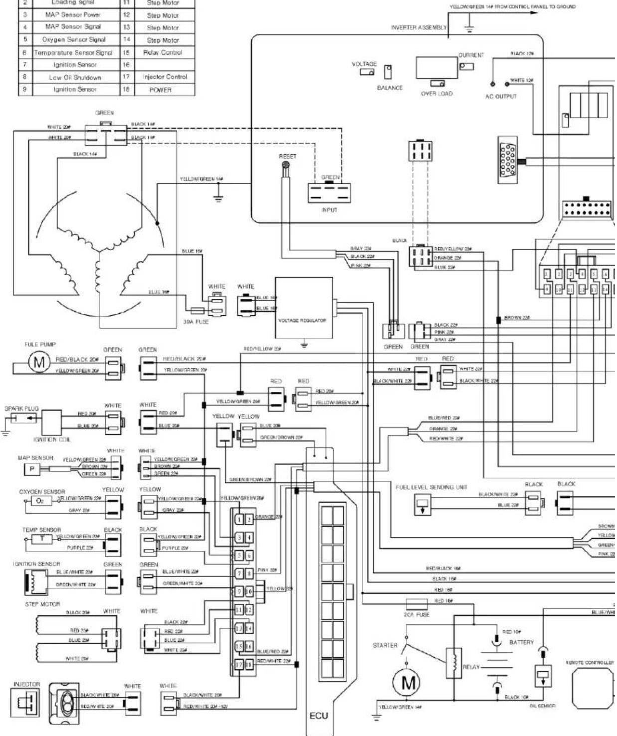
LIFAN POWER USA
DIAGRAM

Lifan Power USA is proud to offer its extensive line of Lifan power equipment.
Lifan Power USA is the sole distributor for Lifan power equipment in the United States. Lifan's unmantched investment in research & development ensures quality engines, generators, pressure washers, and water pumps at an extraordinary value. Lifan continues to be an innovator and presently holds over 4,000 international patents. Product performance has earned Lifan the reputation of dependability and value in all their international markets.
Lifan has been manufacturing and selling innovative and value driven products worldwide for over 20 years. Lifan is distributed in over 100 countries. Lifan is one of the largest publicly traded companies in China with sales over one billion dollars annually and 14,000 employees.
LIFAN POWER USA
As the largest engine manufacturer in China, Lifan builds more than five million small engines each year. This worldwide presence has been made possible by producing equipment that is durable, reliable, and rugged for any market.
Lifan Power USA prides itself in standing behind all Lifan products with our comprehensive warranty policy. Lifan Power USA continues to offer the highest level of service and support in the industry. With proven performance and unmatched value, Lifan power equipment will always keep you running.
All information in this publication is based on the latest product information available at the time of approval for printing. EquipSource, LLC reserves the right to make changes at any time without notice and without incurring any obligation. The copyright of this document belongs to EquipSource, LLC. No part of this publication may be reproduced without the written permission of EquipSource, LLC.
- OPERATING INSTRUCTIONS & OWNERS' MANUAL
- LIFAN POWER USA
- OPERATING INSTRUCTIONS AND OWNER'S MANUAL
- ENERGY STORM SERIES ESI-3100IER-EFI
- ATTENTION: RENTAL COMPANIES AND PRIVATE OWNERS WHO LOAN THIS EQUIPMENT TO OTHERS
- WARNING
- SPECIAL HAZARDS
- EQUIPMENT PROTECTION FACTS
- TABLE OF CONTENTS
- PLEASE READ THE FOLLOWING INSTRUCTIONS
- PREFACE
- SAFETY INSTRUCTIONS
- HAZARD SYMBOLS AND MEANINGS
- DANGER
- WHEN ADDING OR DRAINING FUEL
- WHEN TRANSPORTING OR REPAIRING EQUIPMENT
- WHEN STORING FUEL OR EQUIPMENT CONTAINING FUEL
- WHEN STARTING EQUIPMENT
- WHEN OPERATING EQUIPMENT
- UNINTENTIONAL SPARKING CAN RESULT IN FIRE OR ELECTRICAL SHOCK
- CAUTION
- AUTOMOTIVE TYPE ELECTRONIC FUEL INJECTION SYSTEM
- 12 LIFAN POWER USA
- CONTROLS AND FEATURES
- 13 LIFAN POWER USA
- 14 LIFAN POWER USA
- 17 LIFAN POWER USA
- BOX CONTENTS
- PRE-OPERATING INSTRUCTIONS: ASSEMBLY
- UNPACKING THE GENERATOR
- AUTO IDLE CONTROL SWITCH
- DUO POWER
- PARALLEL CONNECTION FEATURE
- PRE-OPERATING INSTRUCTIONS: SETUP
- PRE-OPERATING
- INSTRUCTIONS: SETUP
- FUEL AND ITS VAPORS ARE EXTREMELY FLAMMABLE AND EXPLOSIVE. FIRE OR EXPLOSION CAN CAUSE SEVERE BURNS OR DEATH
- WHEN ADDING FUEL
- ADD FUEL: REFER TO CONTROLS AND FEATURES SECTION FOR DIAGRAMS
- UNDERSTANDING YOUR BATTERY
- BATTERY ASSEMBLY AND MAINTENANCE
- MANUAL
- GOT A QUESTION
- ASK A QUESTION
- QUESTION AND ANSWER
- NEVER START OR SHUTOFF THE GENERATOR WITH ELECTRICAL LOADS CONNECTED AND IN THE OPERATIONAL MODE (ON SWITCH ACTIVATED)
- 28 LIFAN POWER USA
- PULL-START (RECOIL) MODELS
- YOUR ESI 3100IER-EFI IS RECOIL START
- REMOTE START MODELS
- OPERATION OF GENERATOR HOW TO USE YOUR GENERATOR
- OUTPUT AND OVERLOAD INDICATOR
- LOW OIL ALARM SYSTEM
- STOPPING THE GENERATOR
- EMERGENCY SHUTDOWN
- NORMAL SHUTDOWN
- REMOTE SHUTDOWN
- STORING THE UNIT
- MAINTENANCE
- OIL CHANGE PROCEDURES
- PROPER MAINTENANCE OF THE UNIT WILL INCREASE THE LIFE OF YOUR PRODUCT. THE OIL MUST BE CHANGED ON A REGULAR BASIS FOR PROPER OPERATION, AND RELIABILITY AND TO ALSO MAINTAIN THE WARRANTY ON THIS PRODUCT
- AIR CLEANER MAINTENANCE
- SPARK PLUG MAINTENANCE
- RECOMMENDED SPARK PLUG: F7RTC
- FUEL SYSTEM MAINTENANCE
- 37 LIFAN POWER USA
- SPARK ARRESTOR MAINTENANCE
- TRANSPORTING THE GENERATOR
- LONG-TERM STORAGE OF THE GENERATOR
- SHORT-TERM STORAGE
- EXERCISING THE GENERATOR
- TROUBLESHOOTING
- IF THE ENGINE WILL NOT START
- UNIT DOES NOT PROVIDE ELECTRICAL CURRENT
- AC APPLICATION
- POWERING 12V DC DEVICES
- BACK-CHARGING THE GENERATOR BATTERY
- JUMP-STARTING THE GENERATOR
- NO OUTPUT AT THE DC RECEPTACLE
- DIGITAL DISPLAY
- ERROR - FAULT CODES DIGITAL READ-OUT
- CONVERTING AMPS OR HORSEPOWER INTO WATTS
- NO ELECTRIC MOTORS
- LIMITED WARRANTY POLICY
- LENGTH OF WARRANTY
- OWNER'S RESPONSIBILITY
- REGISTERING YOUR PRODUCT
- EXCLUSIONS
- DISCLAIMER OF IMPLIED WARRANTIES
- GOVERNING LAW/ CONSENT TO JURISDICTION AND FORUM SELECTION
- OWNER'S WARRANTY RESPONSIBILITIES
- APPENDIX
- EXPLODED VIEW & PARTS LIST
- 54
- [NO TEXT]
- APPENDIX: WIRING DIAGRAM
- LIFAN POWER USA IS PROUD TO OFFER ITS EXTENSIVE LINE OF LIFAN POWER EQUIPMENT
Brand : Lifan
Model : Energy Storm 3100iER-EFI
Category : Generator