
EF-30i - Deep fryer APW Wyott - Free user manual and instructions
Find the device manual for free EF-30i APW Wyott in PDF.


| Product Type | Commercial Electric Deep Fryer |
| Model | EF-30i |
| Brand | APW Wyott |
| Dimensions (W x D x H) | 13.5 x 26 x 15 inches |
| Weight | 55 lbs |
| Power Supply | 208-240V, 60Hz, single phase, 9.5 kW |
| Oil Capacity | 30 lbs (approx. 4 gallons) |
| Basket Capacity | 2 baskets, each holding up to 5 lbs of food |
| Temperature Control | Adjustable thermostat, 250°F - 375°F |
| Construction | Stainless steel body and fry pot |
| Features | Twin baskets with cool-touch handles; safety shut-off; indicator lights; quick oil drain valve |
| Maintenance | Daily oil filtration recommended; removable fry pot for cleaning |
| Safety | High-limit safety thermostat; automatic shut-off in case of overheating |
| Spare Parts | Replacement baskets, thermostats, heating elements, drain valve kits available |
| General Info | Countertop design; ideal for small to medium foodservice operations |
Frequently Asked Questions - EF-30i APW Wyott
User questions about EF-30i APW Wyott
0 question about this device. Answer the ones you know or ask your own.
Ask a new question about this device
Download the instructions for your Deep fryer in PDF format for free! Find your manual EF-30i - APW Wyott and take your electronic device back in hand. On this page are published all the documents necessary for the use of your device. EF-30i by APW Wyott.
USER MANUAL EF-30i APW Wyott
DESIGNED SMART. BUILT SOLID®
INSTALLATION AND OPERATING INSTRUCTIONS
Electric Fryers
Model: EF-30i

natural_image
Exterior view of a modern kitchen appliance with dual grilles and control panels (no visible text or symbols)
WARNING: California Residents Only. This product can expose you to chemicals including chromium which is known to the State of California to cause cancer and birth defects or other reproductive harm. For more information go to www.P65Warnings.ca.gov.

FOR YOUR SAFETY: Do not store or use gasoline or other flammable vapors and liquids in the vicinity of this or any other appliance.


WARNING: Improper installation, operation, service or maintenance can cause property damage, injury or death. Read and understand these instructions thoroughly before positioning, installing, maintaining or servicing this equipment.


WARNING: Initial heating of oven may generate smoke or fumes and must be done in a well-ventilated area. Overexposure to smoke or fumes may cause nausea or dizziness.


P/N 882209 REV A 11/18
APW Wyott Food Service Equipment Company
1307 N. Watters Road, Suite 180 • Allen, TX 75013
APW Wyott Food Service Equipment Company is a wholly owned subsidiary of Standex International Corporation.
TABLE OF CONTENTS
| SECTIONITEM......PAGE | SECTION ITEM......PAGE | ||
| 1 | Safety Precautions/Safety Information......2 | 8 | Service......8 |
| 9 | Troubleshooting Guide......10 | ||
| 2 | General Information......4 | 10 | Suggested Temperature & Times......11 |
| 3 | Description......4 | ||
| 4 | Installation & Supply Connections.4 | 11 | Replacement Parts List & Exploded Views......11 |
| 5 | Thermostat Calibration......5 | ||
| 6 | Maintenance......6 | 12 | Wiring Diagram......15 |
| 7 | Cleaning......8 | 13 | Warranty......17 |
APW Wyott takes pride in the design and quality of our products. When used as intended and with proper care and maintenance, you will experience years of reliable operation from this equipment. To ensure best results, it is important that you read and follow the instructions in this manual carefully.
Installation and start-up should be performed by a qualified installer who thoroughly read, understands and follows these instructions.
If you have questions concerning the installation, operation, maintenance or service of this product, write Technical Service Department: APW Wyott Foodservice Co., Inc., 1307 N Watters Rd. Suite 180, Allen, TX 75013.
1. SAFETY PRECAUTIONS

CAUTION: These models are designed, built, and sold for commercial use. If these models are positioned so the general public can use the equipment make sure that cautions, warnings, and operating instructions are clearly posted near each unit so that anyone using the equipment will use it correctly and not injure themselves or harm the equipment.


WARNING: Check the data plate on this unit before installation. Connect the unit only to the voltage and frequency listed on the data plate. Connect only to 1 or 3 phase as listed on the data plate.


WARNING: Electrical and grounding connections must comply with the applicable portions of the national electrical code and/or other local electrical codes.


WARNING: Disconnect device from electrical power supply and place a Tag Out-Lockout on the power plug, indicating that you are working on the circuit.


WARNING: Install per the spacing requirements listed in the installation section of this manual. We strongly recommend having a competent professional install the equipment. A licensed electrician should make the electrical connections and connect power to the unit. Local codes should always be used when connecting these units to electrical power. In the absence of local codes, use the latest version of the National Electrical Code.


WARNING: This device should be safely and adequately grounded in accordance with local codes, or in the absence of local codes, with the National Electrical code, ANSI/NFPA 70, Latest Edition to protect the user from electrical shock. It requires a grounded system and a dedicated circuit, protected by a fuse or circuit breaker of proper size and rating. Canadian installation must comply with the Canadian Electrical Code, CSAC22.2, as applicable.

CAUTION: Do not set the fryer with its back flat against the wall. It will not operate properly unless there is at least 3" breathing space behind fryer.


WARNING: A factory authorized agent should handle all maintenance and repair. Before doing any maintenance or repair, contact APW Wyott.

WARNING: Never clean any electrical unit by immersing it in water. Turn off before cleaning surface.


WARNING: An earthing cable must connect the appliance to all other units in the complete installation and from there to an independent earth connection.


NOTICE: The unit when installed must be electrically grounded and comply with local codes, or in the absence of local codes, with the national electrical code ANSI/NFPA70- latest edition. Canadian installation must comply with CSA-STANDARD C.22.2 Number 0 M1982 General Requirements-Canadian Electrical Code Part II, 109-M1981- Commercial Cooking Appliances.

WARNING: SHOCK HAZARD - De-energize all power to equipment before cleaning the equipment.

NOTICE: This product is intended for commercial use only. Not for household use.


NOTICE: Local codes regarding installation vary greatly from one area to another. The National Fire Protection Association, Inc. states in its NFPA96 latest edition that local codes are “Authority Having Jurisdiction” when it comes to requirement for installation of equipment. Therefore, installation should comply with all local codes.


CAUTION: This product when stacked, has more than one power supply connection point. Disconnect all power supplies before servicing.


CAUTION: Suitable for installation on combustible floor when installed with legs or casters provided.


WARNING: SHOCK HAZARD - Do not open any panels that require the use of tools.

Immediately Inspect For Shipping Damage
All containers should be examined for damage before and during unloading. The freight carrier has assumed responsibility for its safe transit and delivery. If equipment is received damaged, either apparent or concealed, a claim must be made with the delivering carrier.
A) Apparent damage or loss must be noted on the freight bill at the time of delivery. It must then be signed by the carrier representative (Driver). If this is not done, the carrier may refuse the claim. The carrier can supply the necessary forms.
B) Concealed damage or loss if not apparent until after equipment is uncrated, a request for inspection must be made to the carrier within 15 days. The carrier should arrange an inspection. Be certain to hold all contents and packaging material.
Installation and start-up should be performed by a qualified installer who thoroughly read, understands and follows these instructions.
2. GENERAL INFORMATION
General Installation:
- Always clean equipment thoroughly before first use (see "General Cleaning Instructions").
- Check rating label for your model designation & electrical rating.
- For best results, use stainless steel countertops.
- Attach legs to unit.
General Operation Instructions:
- All food service equipment should be operated by trained personnel.
- Do not allow your customers to come in contact with any surface labeled "CAUTION HOT".
- Where applicable, never pour cold water into dry heated units.
- Where applicable, do not cook, warm or hold food directly in liner pans (well) pans. Always use steamtable pans/insets, etc.
- NEVER hold food below 140°F.
General Cleaning Instructions:
- NEVER clean any electrical unit by immersing it in water. Turn unit off and allow it to cool down before surface cleaning.
- Always clean equipment thoroughly before first use. Clean unit daily. Except where noted on charts: Use warm, soapy water. Mild cleansers & PLASTIC scouring pads may be used to remove baked-on food and water scale on metal units.
- Unplug electrical units before cleaning or servicing. All service should be performed by an APW Wyott authorized service agency.
General Troubleshooting:
Always ask and check:
- Is the unit connected to a live power source?
- Check circuit breaker.
- Is power switch "ON" and pilot light glowing?
- Check rating label. Are you operating unit on proper voltage?
If the above checks out and you still have problems, call an APW Wyott authorized service agency.
3. DESCRIPTION
Electric Fryers:
These electric units are designed for countertop operation. They are used for producing evenly cooked, perfectly fried products.
4. INSTALLATION & SUPPLY CONNECTION
Installation
- Follow General Installation Instructions on previous page.
Screw legs into the permanently fastened nuts on the four corners of the unit and tighten by hand. Level the fryer by turning the adjustment screw at the bottom of each leg. Do not slide unit with legs mounted, lift if necessary to move unit.
Supply Connection
- All units are provided with two terminal blocks for field wire connections on the rear of the unit. The large terminal block (marked X-Y-Z) is for power supply connections. The smaller auxiliary terminal block (marked 1-2-3) is for connection to a fire protection circuit, or a danger switch.
All units are provided with two knockouts: a 3/4 conduit size for power supply and a 1/2" conduit size for auxiliary terminal block wires. Both knockouts are located on the rear leg channel and are accessible by removing the rear panel. - Remove rear panel. Mount suitable 3/4" conduit fitting in power supply knockout. The knockout hole for 1/2" conduit fitting is covered with a closure plug. Remove this plug and mount a 1/2" conduit fitting for connections to auxiliary terminal block.

Caution: Do not remove closure plug covering 1/2" size knockout opening if connections to a fire protection circuit are not required. Removal of the closure plug under this condition may result in a shock hazard.

- Connect field wire to the power terminal block as indicated on wiring diagram. Wire must be of the type suitable for 90 °C service and of thickness as indicated on marking on rear panel.
Field wire connections to auxiliary terminal block must be of size indicated on marking on rear panel and suitable for 90 °C service. Lead wires to the auxiliary terminal block must be connected per instructions on the wiring diagram located on rear panel; depending on whether the fire protection circuit has a Normally Open (N.O.) or a Normally Closed (N.C.) Switch.
The auxiliary terminal block wiring must not be changed if connections to a fire protection system are not made. The fryer is factory assembled for operating without connections to a fire protection system.
For testing, the rated amperages are listed below:
| 1 Phase | |
| 208V 2 | 40V |
| 58 50 | |
| 3 Phase | ||||||
| 208V 240V | ||||||
| ||||| | ||| | |||||
| 29 50 | 29 | 25 44 | 25 | |||
NOTE: These values are nominal ratings. Field wire connections must be capable of withstanding anticipated surges.
Replace rear panel. Ensure the equipment is grounded by installing a grounding lead to ground lug located near terminal block.

Caution: Installing personnel should be guided by National Electrical Code NFPA Number 70-1978(Latest Edition), and applicable local codes.

5. THERMOSTAT CALIBRATION
Checking Thermostat Calibration:
The fryer thermostat is carefully calibrated at the factory so that dial settings match actual frying compound temperatures. Field re-calibration is seldom necessary unless the unit has been mishandled in transit or abused. Re-calibration should not be resorted to unless considerable experience with cooking results definitely proves that the control isn't maintaining the temperature to which the dial is set.
- To check compound frying temperatures when re-calibrating, use a precision test instrument, or a good grade mercury thermometer. Fill fry tank with frying compound to "FULL" mark.
- Frying compound temperature should be checked at the center of the tank, approximately 1" to 1 1/2" below surface of frying compound.
-
Turn the dial of the thermostat being checked to the 350 °F mark.
-
Allow temperature to stabilize, or until the thermostat cycles to "OFF" three times after starting with cold frying compound. With power "ON", read highest and lowest frying compound temperature, as thermostat cycles through at least two cycles. Average the reading.
- Thermostat should be re-calibrated if temperature reading is not within 10 degrees of the control knob setting (350°F +/- 10°F). If re-calibration is required, continue with steps 6, 7, 8 and 9.
- Remove control knob by grasping outer edge and pulling straight out, without twisting or turning.
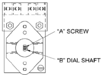
- Hold thermostat dial shaft "B" (Figure 1) stationary with pliers, and with a screwdriver, turn screw "A" clockwise to obtain a lower temperature; or counter-clockwise for higher temperature. Each 14 turn ( 90^ rotation) of screw "A" represents 18^ F.
- Replace thermostat control knob.
- Recheck thermostat as in Steps 4 and 5 above. If the fat temperature is not within 20 degrees of dial setting (350 °F +/- 20 °F), it means that the sensing element is inoperative and the thermostatic control should be replaced.
6. MAINTENANCE
FIGURE 1

Removing Fry Tanks:
a. Remove fry baskets.
b. Carefully grasp the black handle, CAUTION: may be hot, on the end post on top rear corner of the fryer with the left hand, and the element lift handle resting on fry tank front, with right hand.
c. Lift the element handle while at the same time pulling the plastic handle. This will permit lifting the elements to just above frying compound level in tank. The element can be left in this position for draining frying compound.
d. Again, lift the element handle while pulling the plastic handle, until the elements lock themselves at a higher position.
e. Firmly grasp both handles of fry tank and lift it out.
f. After replacing the fry tank, simply pull the plastic handle; and at the same time, pull down the element handle until the elements rest on fry tank bottom.
g. Both the lifting out and lowering of elements can be done in one swing, without stopping at the intermediate position.
Filling Fry Tank:
- Ensure circuit breaker is at the -ON- position. This is done by pressing the "RESET" or "ON" part of the red rocker handle on the front panel
- Set the thermostat to "OFF" and turn on the power switch marked "ON-OFF" to turn unit on. The green indicator lamp will come on. Turn the thermostat knob to the 300^ mark and a yellow cycling light marked "HEAT ON" will come on. Turn the power switch to the "off" position. The fryer control circuit has now been checked and the fryer is ready for use.
Caution: Do not leave elements on without frying compound in the tank.

a. Fill the fry tank to the "FULL" mark with approximately 30 lbs of liquid or melted frying compound.
Do not overfill.
Note: Do not use solid frying compound unless the fryer is equipped with a melt cycle option. Air holes caused when packing solid frying compound into the fryer can cause hot spots on the heating element sheath, resulting in momentary overheating of some of the frying compound and premature frying compound breakdown. It can also damage the heating elements. If it is necessary to use solid frying compound, it must be melted before adding to fry tank.
Turn the thermostat to the desired frying temperature and switch the unit “ON”. The yellow “HEAT ON” light will stay on until the temperature set on the thermostat is reached, then the light cycles off. The fryer is now ready to begin frying. After a load has been fried, do not lower the next load into the frying compound until the “HEAT ON” light cycles off.
b. Do not allow frying compound level to drop more than 1/2" below the "FULL" mark. For proper operation of the fryer and good frying results, the frying compound level should be maintained.
c. Use a quality frying compound.
d. Filter the frying compound frequently at least once a day.
e. Skim out food particles frequently with the strainer/skimmer.
f. Add at least 15% (of fry tank capacity) of fresh frying compound daily - more if possible - without overloading the tank. If 15% of the frying compound is not used during frying, remove some of the frying compound for other use (gravy, griddle frying. etc.) to permit adding fresh frying compound.
g. Do not overload the fry baskets. Approximately half-full or even less is correct. If foods are taking longer to fry than the chart shows or are not browning. Overloading is a probable cause.
h. Prepare the food properly:
i. Keep salt out of the frying compound. Do not salt foods with the basket above the kettle.
j. Assure a good thermostat operation.
k. Keep the fry tank and elements clean.
- If the fryer is equipped with the "Automatic Melt Cycle" option, the fry tank can be filled with solid frying compound. The melt cycle can also be used to melt frying compound which has solidified since its last usage.
To operate the melt cycle, push the white switch marked “MELT ON” to “ON”. The fryer may be left unattended during the melt cycle operation. It takes approximately 18 minutes to melt 30 lbs of solid frying compound. After the solid frying compound has melted, push the melt cycle switch to “OFF”. The fryer will then heat the frying compound to the temperature set on the thermostat.
7. CLEANING
- Follow General Cleaning Instructions on Page 4.
a. Before the first time use, clean the protective oil from the bright parts and interior of tank with a solution of washing soda or other grease dissolving material.
- The frequency of cleaning should depend on the load conditions. Set a definite cleaning schedule corresponding to how hard the kettle is used. Cleaning should be done at least once a week.
a. Turn the thermostat to "OFF" and allow unit to cool down.
b. Lift the elements to drain position. Wire brush or scrape elements to remove any solids adhering to the elements.
c. Raise the elements. Lift out fry tank. Strain the frying compound into a clean container. d. Replace empty fry tank, lower elements to rest inside the tank.
e. Add water to the "FULL" mark on tank.
f. Add any good grade of Cleaner, following cleaner instructions.
g. Turn the thermostat to 250^ F and let the heating unit bring the solution to a boil.
h. Boil long enough to loosen or dissolve all varnish or carbon deposits, approximately 30 minutes.
i. Turn the unit off and lift out the elements to drain position.
j. If necessary, clean the thermostat bulbs using a long-handled fiber or plastic brush and mild soap solution.
k. Rinse with clean water to remove all cleaning mixture.
I. Lift out the fry tank and drain. Repeat steps j and k with fry tank.
m. Rinse the inside of the tank with 2 cups of vinegar.
n. Rinse with clean water until the vinegar odor is gone. The fry tank must be thoroughly rinsed, since even a trace of cleaner left inside the tank will ruin frying compound.
o. Dry thoroughly. Replace the tank and lower the elements.
p. Shut the unit off and cover tank until ready for further use.
q. Thin films of oil subjected to frying temperatures quickly form into a gummy consistency. In order to avoid these gum formations, keep all other surfaces of the unit clean by polishing stainless steel surfaces with a damp cloth. To remove discolorations or oil film, a nonabrasive cleaner may be used.
8. SERVICE
- Caution:
a. Before servicing the unit, make certain the fry tank frying compound and elements are cool enough to avoid burns.
b. Before opening component access panels, ensure the electrical power supply cord to main terminal block and power supply to the auxiliary terminal block BOTH have been disconnected.
- To replace "ON-OFF" switch, yellow cycling light or circuit breaker, white "MELT ON" switch and melt cycle control assembly for melt cycle option:
a. Remove the thermostat control knob by grasping outer edge and pulling straight out, without twisting or turning.
b. Remove two screws at top of front panel. Pull top edge to open.
c. Disconnect leads to switch, light or circuit breaker and remove the damaged component. Mark
disconnected leads to identify them.
d. Mount the new circuit breaker (or melt cycle control) with fasteners provided. The new switch or light is snapped into place from the front of the panel.
e. Connect leads to corresponding terminals on new component. Check completed circuit against circuit diagram on rear panel.
f. Reverse steps a and b to close front panel.
- To replace magnetic contactor, terminal block, ground lug or auxiliary terminal block:
a. Remove four screws securing the rear panel to the unit. Let the rear panel fall down straight before pulling it out.
b. Disconnect leads to the damaged component.
c. Connect the leads to corresponding terminal on the new component.
d. Remove screws securing the damaged component to the mounting panel.
e. Remove the damaged. component .and install a new component, in the same position.
f. Check completed circuit against circuit diagram on rear panel.
g. Mount the rear panel and put unit in operation.
- To replace blown fuses or fuse block:
a. Open rear panel as in step 3a above.
b. Remove damaged fuses and replace with 40 ampere one-time fuse.
c. To replace fuse block, remove fuse and disconnect wire leads to the damaged fuse block. Mark disconnected leads to identify them.
d. Replace new fuse block in the same position.
e. Connect leads to corresponding terminal on new fuse block. Check completed circuit against circuit diagram on rear panel.
- To replace element:
a. Remove screws securing pivotal head cover to pivotal head. Remove pivotal head cover and gasket.
b. Lift up the elements to drain position.
c. Remove thermostat bulb and capillary tube clamps.
d. Remove element support assembly.
e. Disconnect leads to element and mark them for identification.
f. Remove the element retaining nuts inside the pivotal head.
g. Remove element. Mount the new element and reverse steps a through f to reassemble.
- To replace hi-limit thermostat:
a. Remove pivotal head cover and gasket as in step 5a.
b. Remove hi-limit thermostat bulb and capillary tube clamps from element.
c. Dislodge capillary bushing from hole in pivotal head.
d. Remove bushing and thread the thermostat capillary and bulb through hole in pivotal head.
e. Disconnect leads to the damaged hi-limit thermostat and transfer them to corresponding leads on the new thermostat.
f. Remove screws securing the thermostat.
g. Secure new hi-limit thermostat with screws and reverse steps a through d to reassemble.
- To replace cycling thermostat:
a. Remove front panel (steps 2a and 2b), rear panel (step 3a), pivotal head cover, and gasket (step 5a).
b. Remove cover on back of end post, located on right rear corner of the unit.
c. Remove thermostat capillary and bulb from the pivotal head as in steps 6b through 6d.
d. Disconnect nuts securing the thermostat coil to end post and to pivotal head. Both are accessible from rear of end post.
e. Disconnect leads to the damaged thermostat and mark them for identification.
f. Remove screws securing the thermostat to front panel.
g. Maneuver the thermostat to rear of the unit (through right side passage) and then into the right side end post (through opening on top panel).
h. Remove thermostat along with bulb and capillary from the opening on back of right side end post.
i. Wind the thermostat coil (supplied with new thermostat) around the capillary of new thermostat, at approximately the same position from bulb as on the damaged thermostat.

Note: The thermostat coil should cover approximately 11" to 12" of capillary length.

j. Wrap the portion of thermostat capillary which is covered by the thermostat coil, into approximately two turns of 1-1/2" to 2" diameter.
k. Reassemble the thermostat by reversing steps 7a through 7h.
- TROUBLESHOOTING GUIDE
| Possible Cause | ||||||||||||||||
| Frying temperature too high/overheating.(Check thermostat) | Frying temperature too low. (Check thermostat) | Overloading the fry tank. | Improper draining of food after frying. | High moisture content in food being fried. | Inadequate frying compound turnover. | Improper preparation of food. | Contamination of frying compound. (Due to salt or other foreign material) | Frying in foam. | Food being fried may be of poor quality. | Drip-back from exhaust stack. | Poor quality of frying compound (Either initially or after excessive use) | Cooking time too short. | Inadequate filtering of frying compound. Excessive crumbs in fry tank. | Keeping food in frying compound after cooking. | Inadequate cleaning of fry tank. | |
| Problem | ||||||||||||||||
| Excessive and premature foaming. | XXXXXXXXX | |||||||||||||||
| Greasy food/excessive frying compound absorption. | XXXXXXXXX | |||||||||||||||
| “Objectionable” odor or flavor of frying compound. | XXXXXXXXX | |||||||||||||||
| “Objectionable” flavor of fried food. | XXXXXXXXX | |||||||||||||||
| Excessive smoking of frying compound. | XXXXXXXXX | |||||||||||||||
| Excessive darkening of frying compound. | XXXXXXXXX | |||||||||||||||
| Frying compound won’t hold heat. | XXXX | |||||||||||||||
| Food crust color not brown. | XXXXXXXXX | |||||||||||||||
| Rapid breakdown of frying compound. | XXXXXXXXX | |||||||||||||||
- SUGGESTED TEMPERATURES AND TIMES
| FOOD CONTROL | SETTING (°F) | TIME(MINUTES) |
| DOUGHNUTS SEAFOOD | ||
| Cake Type 375° 1 1⁄2 - 2 Fish | Cakes 350° 2 - | 3 |
| Yeast Raised 375° 2 - 2 1⁄2 | Clams 350° 1 - 3 | |
| MEAT Fillets (Small) 350° 3 - 5 | ||
| Cutlets (Less than 1/2" thick) | 350° 5 - 8 Oysters | |
| Chicken Fried Steak | 350° 5 - 8 | Scallops |
| Chops (Very lean) 350° 5 - 8 | Shrimp | |
| MISCELLANEOUS | ||
| Chinese Noodles | 375° 1 - 2 | VEGETABLES |
| Croquettes | 350° 2 - 3 | Egg Plant |
| French Toast 350° 2 - 3 Onion Rings | 35 | |
| Glazed Cinnamon Apples | 300° | 5 - 10 |
| French Fried Sandwiches | 350° | 1 - 2 |
| POULTRY | ||
| Chicken (Large pieces) | 325° | 10 - 5 |
| Chicken (Small pieces) | 350° | 7 - 10 |
| Chicken (Pre-cooked) | 325° - 350° | 3 - 5 |
| Turkey (Small pieces) | 325° | 9 - 10 |
| FOOD CONTROL | SETTING (°F) | TIME(MINUTES) |
| 350° 2 - 5 | ||
| 350° 3 - 5 | ||
| 50° 4 - 6 | ||
| Smelts | 350° 4 - 6 | |
| 350° 5 - 7 | ||
| 3 - 5 | ||
| Potatoes (1/2" Strips,one-operation) | 350° 6 - 9 | |
| Potatoes (Blanch) | 350° | 4 - 6 |
| Potatoes (Brown) | 350° 2 - 3 | |
| Potatoes (Julienne) | 350° | 3 - 5 |
- REPLACEMENT PARTS LIST & EXPLODED VIEWS

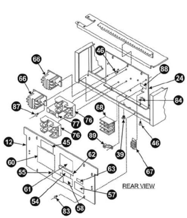
EXPLODED VIEW - EF-30i
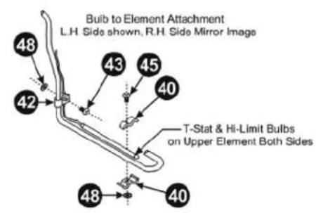

| Item P/N Description Qty | |||
| 1 218 | 100-95 CONTROL | HEAD, ELECTRIC FRYER W/A 1 | |
| 2 143 | 9729 HEATING UN | T ASSEMBLY 1 | |
| 3 138 | 01-00 SWITCH, HI | LIMIT 1 | |
| 4 813 | 0000 8-32 X 3/8 | TYPE T 2 | |
| 5 151 | 5300 IND LIGHT, | RECT, AMB, 250V,2/TABS | 1 |
| 6 148 | 7600 THERMOSTAT | 1 | |
| 7* 870 | 5504 KNOB, THER | MOSTAT | 1 |
| 8 212 | 5502 GROMMET SPLIT | 2 | |
| 9 | 64285901 | CLAMP BULB | |
| 10 | 8944100 CLIP | LEAD | 4 |
| 11 | 8837018 LABEL RESET | 1 | |
| 12 | 8108300 SCREW, PAN HEAD 6-32 X 1/2 4 | ||
| 13 | 8500600 WASHER, LOCK #6 S/S | 4 | |
| 14 | 8402900 NUT, HEX, 6-32 SS | 4 | |
| 15 | 8103400 SCREW, MACH, 6-32 X 1/4" LG. 2 | ||
| 16 | 8455700 NUT, PAL 5/8-18 | 2 | |
EXPLODED VIEW - EF-30i
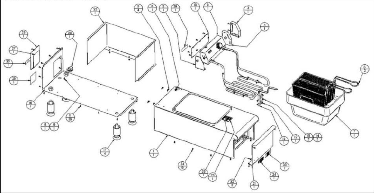
| Item P/N | Description Qty | ||
| 1 6462 | 14-01 TANK WELDMENT 1 | ||
| 2 8206 | 52-01 PIVOT HEAD WELD 1 | ||
| 3 2209 | 1315 FRONT PANEL ASSY 1 | ||
| 4 8203 | 58-11 TOP SUPPORT ASSY 1 | ||
| 5 8200 | 01-05 SIDE PANEL WELD 2 | ||
| 6 8201 | 40-01 LEG PAD WELDMENT 4 | ||
| 7 8206 | 66-01 POST THERM END 1 | ||
| 8 8206 | 60-00 POST LOCKING END | 1 | |
| 10 | 820340-10 TOP CROSS ANGLE | 1 | |
| 11 | 22091312 FRONT 6. REAR CHAN | 2 | |
| 12 | 820342-10 PANEL, REAR | 1 | |
| 13 | 820346-25 | PANEL, TOP | 1 |
| 14 | 820351-25 LINER WELD'T | 1 | |
| 15 | 217074-00 KNOB GUARD | 2 | |
| 16 8134 | 9-00 M/S 8-32 X 3/8 TRHD S/S | 4 | |
| 17 | 820354-25 BOTTOM COVER | 1 | |
| 19 | 820370-00 PIVOTAL HEAD COVER | 1 | |
| 20 | 820467-00 END POST BACK COVER | 1 | |
| 22 | 820472-01 ELEMENT SUPPORT 2 | ||
| 23 | 820474-00 ELEMENT CLAMP BAR | 1 | |
| 24 | 820373-00 CONTCTR MTG PANEL | 1 | |
| 25 | 820372-11 ELEMENT LIFT HANDLE | 1 | |
| 26 | 820368-10 PLUNGER BODY | 1 | |
| 27 | 820369-00 PLUNGER | 1 | |
| 28 | 820371-01 PLUG | 1 | |
| 29 | 820613-01 WIRE PROTECTION STRP | 2 | |
| 31 3100 | 7-23 SPRING, PLUNGER 1 | ||
| 32 3100 | 7-25 GASKET, PIVOTAL HD | 1 | |
| 33 3100 | 7-27 GASKET, END POST | 2 | |
| 34 3101 | 2-25 BASKET, L.H. FRY | 1 | |
| 35 3101 | 2-26 BASKET R.H. FRY | 1 | |
| 36 8705 | 5-04 KNOB, CONTROL | 1 | |
| 37 8705 | 3-07 KNOB, PULL | 1 | |
| 38 2125 | 5-02 GROMMET 2 | ||
| 39 3100 | 7-15 PLUG, 7/8" VENT 2 | ||
| 40 3100 | 7-13 CLAMP, THERMO, BULB 8 | ||
| 41 1604 | 4-00 HOLEPLUG, KNOB INDEX 1 | ||
| 42 3100 | 7-96 CLAMP, TUBE 6 | ||
| 43 8103 | 4-00 M/S PN HD 6-32 X 1/4" S.S 6 | ||
| 44 8105 | 8-00 M/S 6-23-X 3/8" 10 | ||
| 46 8158 | 5-00 M/S TR HD 10-24 X 3/8" S.S 23 | ||
| 47 8162 | 4-00 H.H.C.S. 10-24 X 1/2" S.S. | 8 | |
| 48 8402 | 9-00 HEX NUT 6-32 | 10 | |
| 49 | 8633700 | LEGS, HD 2" Diameter W/Foot | 4 |
| 50 8455 | 5-00 NUT, 5/S"-IS ELASTIC STOP | 1 | |
| 51 8507 | 5-00 FLAT WASHER, 1/4" | 8 | |
| 52 8326 | 6-00 POP RIVET 1/8" X 1/8" S.S | 20 | |
| 54 3100 | 7-97 MARKER, SUPPLY | 1 | |
| 55 8837 | 0-02 MARKER, DISCONNECT | 1 | |
| 58 8837 | 0-15 LABEL, GROUND WRNG 1 | ||
| 59 8837 | 0-18 LABEL, RESET | 2 | |
| 60 8837 | 0-26 WIRING DIAGRAM | 1 | |
| 61 8837 | 0-66 LABEL | 1 | |
| 62 8837 | 0-67 LABEL, FUSE WARNING | 1 | |
| 66 3100 | 7-22 CONTACTOR MAGNETIC | 2 | |
| 67 1107 | 2-02 BLOCK, TERMINAL | 1 | |
| 68 1107 | 2-03 BLOCK, TERMINAL | 1 | |
| 69 1196 | 4-02 WIRE CONNECTOR | 7 | |
| 70 | 782226 | SWITCH, ROCKER | 1 |
| 71 1301 | 6-16 SWITCH, HIGH LIMIT | 1 | |
| 72 1404 | 4-03 ELEMENT, 6000W 208V | 2 | |
| 72a | 14044-04 | ELEMENT, 240 V | 2 |
| 73 1479 | 8-04 THERMOSTAT | 1 | |
| 74 | 14798-05 | SPRING, THERMOSTAT | 1 |
| 75 | 1509600 | PILOT LIGHT, GREEN | 1 |
| 76 1503 | 0-05 FUSE BLOCK | 2 | |
| 77 1503 | 0-06 FUSE | 4 | |
| 78 1503 | 7-03 CIRCUIT BREAKER | 1 | |
| 79 | 15125-04 | INDICATOR LIGHT, AMBER | 1 |
| 80 8423 | 6-01 NUT "U" #10 ZN | 2 | |
| 83 8197 | 1-00 #10 X 3/8" SHT MET SCREW | 6 | |
| 84 8423 | 7-00 #10-24 HEX NUT S.S. | 23 | |
| 86 8413 | 1-00 TINNERMAN NUT | 2 | |
| 87 8141 | 1-00 M/S PN HD 8-32 X 1/2 S/S | 15 | |
| 88 8837 | 0-68 LABEL, CONNECTION | 1 | |
| 89 1114 | 1-00 SOLDERLESS LUG | 1 | |
| 90 | 820547-00 | CAP BULB CLAMP | 1 |
| 91 8145 | 9-00 M/S 8-32 X 1 S/S RD | 2 | |
| 92 8409 | 1-00 NUT 8-32 HEX MET LOCK | 2 | |
| 95 | 2065847 | Logo, APW Wyott Casted | 1 |
| 96 | 820351-30 | INSULATION | 1 |
| 97 8353 | 0-00 RIVET POP 1/8" X 15/64" S/S 2 |
12. WIRING DIAGRAM
WIRING DIAGRAM - EF-30i

flowchart
graph TD
    A["21"] --> B["30"]
    C["73"] --> B
    D["79"] --> E["31"]
    F["29"] --> E
    G["21"] --> H["20"]
    I["70"] --> J["32"]
    K["27"] --> L["29"]
    M["33"] --> N["34"]
    O["13"] --> P["16"]
    Q["14"] --> R["18"]
    S["Coil Shunt Trip"] --> T["33"]
    U["78"] --> V["4"]
    W["16"] --> X["71"]
    Y["18"] --> Z["NC"]
    AA["72"] --> AB["4"]
    AC["66"] --> AD["5"]
    AE["76"] --> AF["1"]
    AG["13"] --> AH["68"]
    AI["67"] --> AJ["15"]
    AK["19"] --> AL["20"]
    AM["(7) Places"] --> AN["34"]
IMPORTANT FOR FUTURE REFERENCE
Please complete this information and retain this manual for the life of the equipment. For Warranty Service and/or Parts, this information is required.
Model Number Serial Number Date Purchased
Notes
APW Wyott EQUIPMENT LIMITED WARRANTY
APW Wyatt Foodservice Equipment Company warrants its equipment against defects in materials and workmanship, subject to the following conditions:
This warranty applies to the original owner only and is not assignable.
Should any product fail to function in its intended manner under normal use within the limits defined in this warranty, at the option of APW Wyott such product will be repaired or replaced by APW Wyott or its Authorized Service Agency. APW Wyott will only be responsible for charges incurred or service performed by its Authorized Service Agencies. The use of other than APW Wyott Authorized Service Agencies will void this warranty and APW Wyott will not be responsible for such work or any charges associated with same. The closest APW Wyott Authorized Service Agent must be used.
This warranty covers products shipped into the 48 contiguous United States, Hawaii, metropolitan areas of Alaska and Canada. There will be no labor coverage for equipment located on any island not connected by roadway to the mainland.
Warranty coverage on products used outside the 48 contiguous United States, Hawaii, and metropolitan areas of Alaska and Canada may vary. Contact the international APW Wyott distributor, dealer, or service agency for details.
Time Period
One year for parts and one year for labor, effective from the date of purchase by the original owner. The Authorized Service Agency may, at their option, require proof of purchase. Parts replaced under this warranty are warranted for the un-expired portion of the original product warranty only.
Exceptions
* Gas/Electric Cookline: Models GCB, GCRB, GF, GGM, GGT, CIP-II, EF, EG, EIIP. Three (3) Year Warranty on all component parts, except switches and thermostats. (2 additional years on parts only. No labor on second or third year.)
* Broiler Briquettes, Rock Grates, Cooking Grates, Burner Shields, Fireboxes: 90 Day Material Only. No Labor.
* Heat Strips: Models FD, FDL, FDD, FDDL. Two (2) Year Warranty on element only. No labor second year.
* Glass Windows, Doors, Seals, Rubber Seals, Light Bulbs: 90 Day Material Only. No Labor
In all cases, parts covered by extended warranty will be shipped FOB the factory after the first year.
Portable Carry In Products
Equipment weighing over 70 pounds or permanently installed will be serviced on-site as per the terms of this warranty. Equipment weighing 70 pounds or under, and which is not permanently installed, i.e. with cord and plug, is considered portable and is subject to the following warranty handling limitations. If portable equipment fails to operate in its intended manner on the first day of connection, or use, at APW Wyott's option or its Authorized Service Agency, it will be serviced on site or replaced.
From day two through the conclusion of this warranty period, portable units must be taken to or sent prepaid to the APW Wyatt Authorized Service Agency for in-warranty repairs. No mileage or travel charges are allowed on portable units after the first day of use. If the customer wants on-site service, they may receive same by paying the travel and mileage charges. Exceptions to this rule: (1) countertop warmers and cookers, which are covered under the Enhanced Warranty Program, and (2) toasters or rollergrills which have in store service.
Exclusions
The following conditions are not covered by warranty:
* Equipment failure relating to improper installation, improper utility connection or supply and problems due to ventilation.
* Equipment that has not been properly maintained, calibration of controls, adjustments, damage from improper cleaning and water damage to controls.
* Equipment that has not been used in an appropriate manner, or has been subject to misuse or misapplication, neglect, abuse, accident, alteration, negligence, damage during transit, delivery or installation, fire, flood, riot or act of god.
* Equipment that has the model number or serial number removed or altered.
If the equipment has been changed, altered, modified or repaired by other than an Authorized Service Agency during or after the warranty period, then the manufacturer shall not be liable for any damages to any person or to any property, which may result from the use of the equipment thereafter.
This warranty does not cover services performed at overtime or premium labor rates. Should service be required at times which normally involve overtime or premium labor rates, the owner shall be charged for the difference between normal service rates and such premium rates. APW Wyatt does not assume any liability for extended delays in replacing or repairing any items beyond its control.
In all cases, the use of other than APW Wyott Authorized OEM Replacement Parts will void this warranty.
This equipment is intended for commercial use only. Warranty is void if equipment is installed in other than commercial application.
Water Quality Requirements
Water supply intended for a unit that has in excess of 3.0 grains of hardness per gallon (GPG) must be treated or softened before being used. Water containing over 3.0 GPG will decrease the efficiency and reduce the operation life of the unit.
Note: Product failure caused by liming or sediment buildup is not covered under warranty.
"THE FOREGOING WARRANTY IS IN LIEU OF ANY AND ALL OTHER WARRANTIES EXPRESSED OR IMPLIED INCLUDING ANY IMPLIED WARRANTY OF MERCHANTABILITY OR FITNESS FOR PARTICULAR PURPOSES AND CONSTITUTES THE ENTIRE LIABILITY OF APW WYOTT. IN NO EVENT DOES THE LIMITED WARRANTY EXTEND BEYOND THE TERMS STATED HEREIN."
9/05


- INSTALLATION AND OPERATING INSTRUCTIONS
- SAFETY PRECAUTIONS
- Immediately Inspect For Shipping Damage
- GENERAL INFORMATION
- General Installation:
- General Operation Instructions:
- General Cleaning Instructions:
- General Troubleshooting:
- DESCRIPTION
- Electric Fryers:
- INSTALLATION & SUPPLY CONNECTION
- Installation
- Supply Connection
- THERMOSTAT CALIBRATION
- Checking Thermostat Calibration:
- MAINTENANCE
- Removing Fry Tanks:
- Filling Fry Tank:
- CLEANING
- SERVICE
- WIRING DIAGRAM
- IMPORTANT FOR FUTURE REFERENCE
- APW Wyott EQUIPMENT LIMITED WARRANTY
- Time Period
- Exceptions
- Portable Carry In Products
- Exclusions
- Water Quality Requirements
Brand : APW Wyott
Model : EF-30i
Category : Deep fryer