
ECO2S KFS2415-1-2S1-ECM - Heating KING - Free user manual and instructions
Find the device manual for free ECO2S KFS2415-1-2S1-ECM KING in PDF.


| Product Type | Electric Furnace |
| Brand | KING |
| Model | ECO2S KFS2415-1-2S1-ECM |
| Series | KF / KFS |
| Installation Orientations | Vertical upflow, downflow, horizontal |
| Minimum Clearance | 1 inch |
| Power Supply | 240 V single phase (480 V optional) |
| Heating Element Type | Resistance coils, sequenced |
| Blower Motor | 1/3 HP, multi-speed (low, medium, high) |
| Maximum Airflow | 2120 CFM (at 0.1 in. static) |
| Control System | Low voltage thermostat (24 VAC) |
| Circuit Breakers | Built-in 60 A per circuit |
| Air Filter Size | 1 in. × 16 in. × 20 in. |
| Dimensions (Case) | 30.5 in. tall (width and depth vary by model) |
| Weight | Approximately 74 to 85 lbs (depending on configuration) |
| Safety Features | High limit control, circuit breakers, grounding terminal |
| Accessories | Combustible floor base, cooling coil, electronic air cleaner |
Frequently Asked Questions - ECO2S KFS2415-1-2S1-ECM KING
User questions about ECO2S KFS2415-1-2S1-ECM KING
0 question about this device. Answer the ones you know or ask your own.
Ask a new question about this device
Download the instructions for your Heating in PDF format for free! Find your manual ECO2S KFS2415-1-2S1-ECM - KING and take your electronic device back in hand. On this page are published all the documents necessary for the use of your device. ECO2S KFS2415-1-2S1-ECM by KING.
USER MANUAL ECO2S KFS2415-1-2S1-ECM KING
king Electric Furnace
Installation Instructions
KF and KFS Series
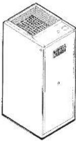
KING furnaces can be installed with a minimum of 1 inch clearance for compact, space saving installations in either vertical upflow, downflow or horizontal position.
When installed in the downtown position, the Combustible Floor Base Accessory must be used.
CHECK furnace to be sure blower wheel is free-turning, and that element assemblies are in place. Be sure titer is in proper position and not tom or damaged.
NOTE: the attached Underwriters Laboratories' label pertains to the furnace only. It does not cover any air cooler, condensing unit or air cleaner, which may be used with the furnace. The optional COU cabinets are designed for slip in addition of an evaporator coil at a later date. Approval of the complete system of air conditioning requires compliance with local ones.
UL
natural_image
Line drawing of a rectangular industrial machine with ventilation grille and control panel (no text or symbols)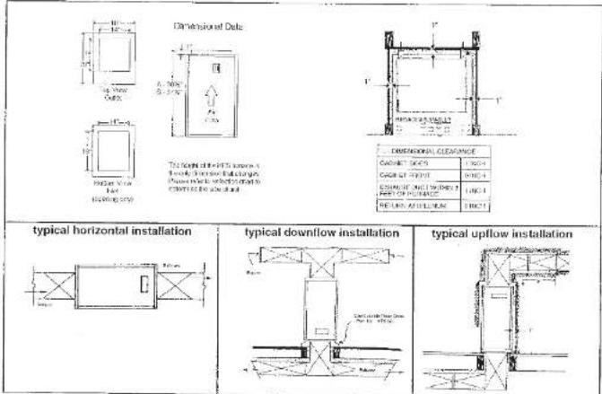
FIELD WIRING: King furnaces come equipped with 60 amp circuit breakers installed for protection of the furnace internal wiring only. They also serve as a connection means when required. A 240 volt single phase circuit must be brought to each circuit breaker in the furnace as shown in the wiring diagram. The terminals are identified as L1-L2, L3-4, L5-6 and L7-L8. The KW size of the furnace determines how many circuits are required. The furnace power and electrical rating table indicates how many circuits each model furnace requires, the size of the branch circuit protection at the distribution panel and the wire size required from distribution panel to the furnace. If there is any questions consult your local and national electric codes. All wiring used must be approved for 75°. NOTE: no wire may have more than 180 VAC potential to ground. This must be checked on installation to avoid motor damage. Unit must be grounded by connection of grounding wire from the distribution panel to the terminal provided in furnace. When the line voltage terminal block option is specified for single strike, wire wiring diagram for wire size and circuit protection requirements.
KING ELECTRIC MFG CO · 9131 10TH AVENUE SOUTH · SEATTLE, WA 98100 · PH: 206 702 0400 · FAX: 206 763 7738 · www.king-electric.com
66048 Rev. 2-7-20
KING ELECTRIC FURNACE
-
Your King electric turbines has been designed to distribute healed air to your living quarters when connected to appropriate ducting.
-
On models KFS & larger, your furnace operates under command of a low voltage wall thermostat.
-
Horials KFS5 through KFS13 enjoy one sequencer relay and thus the thermosat heat antiisperator should be set at 0.4.
-
Records KESPO, then KESSS company two thermal relays, thus the thermostat heat anticipator should be set at 0.8.
- With the thermostel set at 70°F and the temperature drops to about 69°F, the thermostel's internal switch closes its contacts. About 30
seconds later the first heating element and the blower lamp ON. After another 31 seconds the second heating element is turned ON.
continuing in 30 second intervals until at the heating elements in the surface are "ON"
-
When the thermostat is satisfied the "ON" process is reversed with the last element 6. Lower turning "OFF" simultaneously
-
The words of the means could be saline heart loss (rest wall, one max. double, etc.) are much a means comfortable with the thinnest cat in bar
or lower than 71°F. It will take some experience to find your comfort rate setting.
- Your King electric furnace may be equipped with a ceiling coil to accomplish summer cooling. It may also be
equipped with an electronic air cleaner to reduce dust, pollen and other household respiratory irritabilities.
- If your furnace does not have an electronic air cleaner you will need to replace the furnace filter, several times
sturing the year or whenever it becomes dirt clogged.
- The furnace cannot deliver warm air unless.
(a) all electric circuit breakers are turned "ON"
(b) your furnace there are clamped with dust and dust. Air is the vehicle for heat transfer, thus in order to deliver
warm air an equal amount of cold air must be draw back to the humosa
(c) your thermal heat anticipator is not wrong - see paragraph lines and four above.
(2) your cold air return registers are blocked with furniture, throw rugs, etc.
(e) your warm air registers are blocked with furniture, throw rugs, etc.
11 If your furnace is contained with a cooling unit, your "Outdoor Condensate Unit" must be turned "ON" when summer cooling is required and your
impossessed result for included in the 40th quarter, and the consensus information should be 60 at about 70% then 30% of total
(###)
(a) The heat end the model on Limacas with cooling gradients, has a HEAT/OFF & COOL position. The fan
suctico as an AUTOMATIC and ON position
Jal. For heating the suction switch must be moved to HFA7 position and the tan section should be set to AUTOMATU.
Let For continue set the session to COOL and the far section to ON. Thus, the far will run constantly with the outdoor condensing unit running
only when you the thermostat calls for cooling.
(a). You now want the fan to run continuously in either HEAT or COOLING. You will have a custom in ON.
(b) The C/C portion shots down both heat and cooling and also shuts off the lan
(4) In winter, don't leave home with the furnace heated OFF. Instead set your thermostat at about 40°F and leave the furnace return in the
HEAT requires to action the reversibility of fracture of the indoor plumbing
-
-
-
-
-
-
-
-
-
-
-
-
-
-
-
-
-
-
-
-
-
-
-
-
-
-
-
-
-
-
-
-
-
-
-
-
-
-
-
-
-
-
-
-
-
-
-
-
-
-
-
-
-
-
-
-
-
-
-
-
-
-
-
-
-
-
-
-
-
-
-
-
-
-
-
-
-
-
-
-
-
-
-
-
-
-
-
-
- 90.
-
-
-
-
-
-
-
-
-
-
-
-
-
-
-
-
-
-
-
-
-
-
-
-
-
-
-
-
-
-
-
-
-
-
-
-
-
-
-
-
-
-
-
-
-
-
-
-
-
-
-
-
-
-
-
-
-
-
-
-
-
-
-
-
-
-
-
-
-
-
-
-
-
-
-
-
-
-
-
-
-
-
-
-
-
-
-
(2017)57(2): 156-51-12, worked with the electronic wire wire.
MANUFACTURED HOUSING
DOWNFLOW INSTALLATION
-
Select a suitable centralized location of the furnace: A Noel, alone or utility room.
-
The role selection must be a key element that is an arbitrary and not in the initial department of one individual or planned institution of the share
Pecium
- Cut a 15" x 15" opening in the floor opening discharge opium for its location!
d. When the force is saturated for application into the finger corner. Suppose it is the floor with contact (at one point on each side).
-
Cut the dust connector into the base opening and marking holes for cutting where the dust connectors mark out
-
Domains the first component and act to the whole of working on place, and serve out part.
• 2017, the company was a major business center in the United States.
-
30000000000000000000000000000000000000000000000000000000000000000000
-
It necessary out the line of dual connector so that it is below the top of linear base, approximately 1.
-
The fact that the most recent 2016 data were obtained from the result of the results of the recent 2016 data and the time of death
(1) In addition, the resulting results of the _2 are not shown in particular with the present and present, respectively. The result is a negative coefficient estimate that from future
-
Attach the duct connector to floor base using four (45-48) hex head 1/2" soft tapping screws.
-
Present a black-farm house. The house alone does not be able to see the blue and of the brown house located. Decorated Star in
Wehren
-
Make sure power is off on electrical circuits
-
Dammum abses of humerus and labor stents abonded ulcers into an apicalcals, aminian annul plat and rivostatilina ac Instantine an alina
dagram.
- If needed, make sure any return air will lose a free air loss of not less than 195 square inches.

KFS Furnace Airflow Delivery Chart
| Case Size | HP Speed | CFM (Static) | |||||||||
| (0.1) | (0.2) | (0.3) | (0.4) | (0.5) | (0.6) | (0.7) | (0.8) | ||||
| Small Case 30.5" tall | 1/5 | Low | 1090 | 980 | 940 | 890 | 840 | 820 | 800 | 760 | |
| Med | 1260 | 1090 | 1040 | 980 | 930 | 890 | 810 | 780 | |||
| High | 1370 | 1260 | 1220 | 1170 | 1120 | 1090 | 1080 | 990 | |||
| 1/3 | Low | 1700 | 1680 | 1670 | 1660 | 1650 | 1640 | 1630 | 1620 | ||
| Med | 1810 | 1800 | 1790 | 1750 | 1740 | 1730 | 1720 | 1710 | |||
| High | 1960 | 1940 | 1930 | 1910 | 1870 | 1860 | 1850 | 1830 | |||
| Large Case 30.5" tall | 1/5 | Low | 1160 | 1120 | 1090 | 1050 | 1020 | 990 | 980 | 850 | |
| Med | 1310 | 1230 | 1200 | 1150 | 1120 | 1050 | 990 | 910 | |||
| High | 1480 | 1410 | 1390 | 1270 | 1240 | 1180 | 120 | 1040 | |||
| 1/3 | Low | 1860 | 1850 | 1840 | 1830 | 1820 | 1810 | 1790 | 1790 | ||
| Med | 2000 | 1980 | 1960 | 1940 | 1930 | 1920 | 1910 | 1900 | |||
| High | 2120 | 2100 | 2070 | 2050 | 2030 | 2020 | 2010 | 2000 | |||
Airflow delivery chart notes:
-
CFM = cubic feet per minute
-
Static = water column inches
- Performance based on air properties at sea level
- Includes factory provided air filter installed
- Includes electric heating coils installed, no power applied, no heat resistance
- Based on 230V, 5 speed motor.
- 480V motors are single speed only, use high speed for airflow delivery.

FES PART NUMBER DESCRIPTION
| KFP-1000 | Holding Element: 5KW / 240V | |
| KFP-1008A | Holding Element: 5KW / 230V | |
| KFP-1009D | Holding Element: 5KW / 165A | |
| KFP-1000C | Holding Element: 5.2KW / 740V | |
| KFP-1000G | Holding Element: 5.2KW / 240V | |
| KFP-1000E | Holding Element: 4KW / 740V | |
| KFP-1000F | Holding Element: 4KW / 160V | |
| 2 | KFP-1001 | Line Unit Control - 0GT1C |
| 3 | KFP-1009 | Circuit Breaker 80 Amp 10 (passing GE or SO2) |
| KFP-1009A | Circuit Breaker 9 (Pine 50 Amp 50) | |
| 4 | KFP-1002 | Javel Terminal Block 10 KPS KH-18 |
| KFP-1002A | Javel Terminal Block 10 SF20 KFS-15 | |
| KFP-1002B | Javel Terminal Block 30 | |
| 5 | KFP-1004 | Low Voltage Transformer 24024 |
| KFP-1004A | Low Voltage Transformer 20024 | |
| KFP-1004B | Low Voltage Transformer 2/7/24 | |
| KFP-1004C | Low Voltage Transformer 49024 |
Plants note to provide & necessary information for the following: on body bits in packing and carrials for or standarding.
| 6 | KFP-1005 | Sequator (R200 Series) |
| KFP-1006A | Sequator (R201 Series) | |
| KF-1006B | Faday, 28 Amp. RF/80A | |
| KF-1006C | Faday, 28 Amp. RF/80A | |
| 7 | KFP-1006 | Manual Direct Unit |
| KFP-1006A | Manual Pulse Busco | |
| 8 | KFP-1007 | Dual Speed Tin Relay, RB221F |
| 9 | KFP-1008 | Low Voltage Terminal Block |
| 10 | KFP-1009 | Ground Lug |
| 11 | KFP-1010 | 1/5 HP 240V Motor |
| KFP-1010A | 1/5 HP 450V Motor | |
| KFP-1010B | 1/5 HP 340V Motor | |
| KFP-1010C | 1/5 HP 450V Motor | |
| KFP-1010D | 1/5 HP 240V Motor | |
| 12 | KFP-1011 | Gridbox for 1/5 HP 240V/450V |
| 13 | KFP-1012 | Boxer Small (kWV - 260KW) |
| KFP-1012A | Boxer Large (350W - 350W) | |
| 14 | KFP-1013 | Al Filter 1" x 16" x 20" |
KF/KFS 1-PHASE
| CATALOG NO. | KW | DTU (W) | VOLTS | Ampa* | Onion Position | 1 V^st Well Size | Roasted of Pressure | Motor | Temperature Rise, °C | Colared Size | Wt (Wx.) | |||||||||
| L/D 12 | L/D 14 | L/D 16 | L/D 18 | L/D 12 | L/D 14 | L/D 16 | L/D 18 | Volts | HP | Low | Mod | High | ||||||||
| KRS2005-1 | 3 | 10,2 | 268 | 14,4 | 30 | 410 | 1 | 208 | 175 | 42° | 11° | 20° | Dm. A | |||||||
| KRS2405-1 | 4 | 13,6 | 240 | 16,7 | 20 | 410 | 1 | 240 | 195 | 95° | 15° | 10° | Dm. A | |||||||
| KRS2005-1 | 5 | 17,1 | 268 | 24,0 | 40 | 46 | 1 | 268 | 140 | 20° | 16° | 10° | Dm. A | |||||||
| KRS2405-1 | 240 | 23,6 | 30 | 410 | 1 | 240 | 630 | |||||||||||||
| KRS405-1 | 430 | 39,4 | 15 | 414 | ||||||||||||||||
| KFS2006-1 | 6 | 30,5 | 268 | 25 | 40 | 40 | 2 | 268 | 195 | 24° | 22° | 19° | Dm. A | |||||||
| KRS2010-1 | 268 | 48,0 | 60 | 46 | ||||||||||||||||
| KRS2405-1 | 10 | 34,1 | 240 | 41,7 | 60 | 46 | 2 | 268 | 150 | 41° | 31° | 22° | Dm. A | |||||||
| KRS485-1 | 490 | 23,8 | 30 | 410 | ||||||||||||||||
| KRS2415-1 KRS485-21 | 11,8 | 36,2 | 240 | 47,9 | 30 | 48 | 2 | 240 | 150 | 47° | 42° | 20° | Dm. A | |||||||
| 480 | 23,9 | 40 | 48 | |||||||||||||||||
| KRS2015-1 KRS2415-1 | 15 | 51,8 | 268 | 72,1 | 40 | 60 | 60 | 40 | 46 | 3 | 268 | 130 | 61° | 53° | 47° | Dm. A | ||||
| 240 | 52,9 | 50 | 60 | 60 | 410 | |||||||||||||||
| KRS485-1 | 490 | 31,2 | 50 | 46 | ||||||||||||||||
| KRS2416-1 KRS485-2 | 240 | 62,0 | 40 | 60 | 40 | 46 | ||||||||||||||
| 490 | 35,9 | 50 | 60 | 46 | ||||||||||||||||
| KRS2020-1 KRS2405-1 KRS2405-1 | 20 | 68,3 | 268 | 96,2 | 60 | 60 | 46 | 46 | 4 | 268 | 115 | 67° | 73° | 63° | Dm. B | |||||
| 268 | 83,3 | 60 | 60 | 46 | ||||||||||||||||
| KRS2020-1 KRS2405-1 | 430 | 41,7 | 50 | 46 | ||||||||||||||||
| KRS2016-1 KRS2405-1 | 20 | 68,3 | 268 | 96,2 | 60 | 60 | 46 | 46 | 4 | 268 | 130 | 57° | 51° | 47° | Dm. B | |||||
| 268 | 83,3 | 60 | 60 | 46 | ||||||||||||||||
| KRS485-1 | 490 | 41,7 | 60 | 46 | ||||||||||||||||
| KRS2425-1 KRS485-21 | 32,6 | 78,8 | 268 | 93,8 | 60 | 60 | 46 | 46 | 4 | 240 | 110 | 57° | 53° | 47° | Dm. B | |||||
| 450 | 48,5 | 60 | 46 | 46 | ||||||||||||||||
| KRS2025-1 KRS2425-1 KRS485-1 | 25 | 85,3 | 268 | 120,2 | 30 | 60 | 60 | 410 | 46 | 46 | 5 | 268 | 115 | 72° | 62° | 51° | Dm. B | |||
| 240 | 104,2 | 30 | 60 | 60 | 410 | 46 | 46 | |||||||||||||
| KRS2030-1 KRS2405-1 KRS485-1 | 430 | 52,1 | 30 | 60 | 412 | 46 | 46 | |||||||||||||
| KRS2030-1 KRS2405-1 KRS485-1 | 30 | 102,4 | 268 | 144,2 | 60 | 60 | 60 | 46 | 46 | 46 | 8 | 268 | 140 | 66° | 79° | 52° | Dm. B | |||
| 240 | 150,0 | 60 | 60 | 60 | 46 | 46 | 46 | |||||||||||||
| KRS2035-1 KRS2405-1 KRS485-1 | 34,5 | 117,7 | 268 | 149,7 | 50 | 60 | 60 | 47 | 46 | 46 | 46 | 8 | 268 | 140 | 90° | 73° | 71° | Dm. B | ||
| 490 | 71,5 | 40 | 47 | 46 | 46 | |||||||||||||||
KF/KFS 3-PHASE
| Cableing Number | KW | BTU (100) | VOLTS | Ampa | Canal Production kcal/L | Air Max Size mm/L | Number of Components | Motor | Temperature Rise | Capillary Size | Wt (lbs.) | |||
| Volts | HP | Low | Med | High | ||||||||||
| KF5203-9KF5203-9 | 8 | 30.7 | 200 | 24.9 | 4040 | #6#8 | 3 | 208 | 1#5 | 372 | 258 | 258 | Dim A | 74 |
| KF5203-9KF5203-9 | 11.25 | 30.4 | 200 | 31.2 | 4040 | #6#8 | 3 | 208 | 1#5 | 458 | 417 | 314 | Dim A | 74 |
| KF52413-9KF52413-9 | 12 | 40.9 | 240406 | 28.914.4 | 4520 | #6#10 | 3 | 240406 | 1#5 | 426 | 448 | 365 | Dim A | 74 |
| KF52013-9KF52013-9KF52013-9 | 15 | 50.2 | 200240400 | 41.636.1 | 605830 | #6#10 | 3 | 208240400 | 1#5 | 616 | 552 | 479 | Dim A | 74 |
| KF52416-9KF52416-9 | 17.25 | 58.8 | 200400 | 43.336.7 | 6840 | #6#10 | 3 | 240500 | 65 | 706 | 677 | 565 | Dim A | 74 |
| KF52026-9 | 22.5 | 75.8 | 200 | 42.5 | 66 | #6 | 6 | 208 | 65 | 647 | 552 | 468 | Dim B | 85 |
| KF52424-9KF52424-9 | 24 | 81.6 | 240400 | 57.729.8 | 7540 | #6#8 | 6 | 240400 | 1#5 | 656 | 617 | 429 | Dim B | 85 |
| KF52036-9KF52036-9KF52036-9 | 30 | 162.4 | 200240430 | 83.372.236.1 | 11059 | #6#8 | 6 | 208240490 | 1#5 | 969 | 707 | 627 | Dim B | 85 |
| KF52436-9KF52436-9 | 34.5 | 117.7 | 240450 | 82.941.5 | 14060 | #6#2 | 6 | 240150 | 1#5 | 967 | 827 | 711 | Dim B | 85 |
* Does not include motor load, refer to Air Delivery Chart
REFRS ACCESSORIES
| MAY | DESCRIPTION | W |
| 1970-019 | 24% W/ Thermal, Temperature range of 50°C to 60°C | 3 |
| 2011- | Balance to 125°C for a sample dry | 7 |
| 1975-019 | Per impeller heat exchanger (1000 mV) to 2000 mV | 8 |
| 1975-019 | Per impeller heat exchanger (1000 mV) to 2000 mV | 65 |
| 1975-020 | Moole pressure testing method | 1 |
| 1975-021 | Moole pressure testing method for the identification institution | 7 |
| 1975-022 | Control for AC cooling tool by a performance transition. The test is tests | 8 |
| 1975-023 | Control for AC cooling tool by a performance transition. The test is tests | 85 |
KPIKPS BUILT-IN OPTIONS
| Aircraft | DESCRIPTION |
| 4-5 | Engineed controls |
| 40 | Leaseless for 100 W/m 30KW, 1-Pole (Max + 5 PWR Off to 2-Pole for single power power 60kW) |
| LHP | Substrate 100 PWR Solar & Power for 30KW to 100KW Panels |
| LHP | Substrate 100 PWR Solar & Power for 30KW to 100KW Panels |
| 251 | The design of 100% PWR Power panels |
| 252 | The design of 100% PWR Power panels |
CONVERSION OF TORQUE TO HORSEPOWER
The power requirements for the Direct Drive vanies in this section are stated in torque units of ounce-inches and ounce-to-feet.
The formula listed below may be used to convert
toque 20housepoint.
TORQUE IN OZ-IN
| HP=Torque (oz-in) x RPM1006.420 | HP=Torque (oz-1) x RPM84,033 |
| These tables show horsepower as calculated from the above to male. The torque and RPM values need for the calculations are the same as those used in the curves in the catalog. |
| AIR DELIVERY CHART | |||||||
| AIRS (W) | Water tank | Lone | Melt | High | |||
| Falls | Jap. | 500 | 140 | 210 | 770 | 250 | |
| 40 | 230300/420 | 8.41.7 | 775 | 572 | 600 | 630 | 1020 |
| 13 | 330300/420 | 9.21.7 | 1100 | 742 | 1225 | 500 | 1500 |
| 12 | 330300/420 | 3.61.2 | 1250 | 520 | 1400 | 1120 | 1700 |
| New Coke | Fuel | Gas | Milk | ||||
NOCOLPHEN, PCB DIRECT OUT
| DATE | TUES (MM) | Capped Value in $MM (MM) | 426 | 407 | ||||||
| 40 | (20) | 192 | 240 | 278 | 361 | 426 | ||||
| 8 | (2) | 15 | 20 | 25 | 72 | 20 | 20 | |||
| 2016 | 0.26 | 1.97 | 1.14 | 0.21 | 3.25 | 0.28 | 0.43 | 0.50 | 1.57 | |
| 2018 | 5.02 | 1.37 | 1.11 | 0.22 | 2.26 | 9.11 | 5.23 | 3.45 | 6.71 | |
| 2020 | 2.01 | 0.26 | 0.32 | 0.18 | 3.28 | 0.2 | 0.15 | 4.42 | 0.48 | |
| 2022 | 5.02 | 0.25 | 0.11 | 0.16 | 3.22 | 2.21 | 0.22 | 2.30 | 3.44 | |
| 2024 | 0.27 | 4.83 | 2.12 | 0.14 | 8.3 | 7.36 | 9.09 | 8.71 | 1.31 | |
| 2018 | VANOS | Gross Profit (in € million) | |||||||
| Current Value (in € million) | |||||||||
| €20 | €10 | €65 | €50 | 1.90 | 1.52 | 1.23 | 1.07 | 1.452 | |
| 5.2 | 6.0 | 7.5 | 10 | 3.0 | 1.6 | 2.2 | 1.9 | 3.25 | |
| 1520 | 5.75 | 6.30 | 5.80 | 5.14 | 1.38 | 1.22 | 1.07 | 1.01 | 1.56 |
| 1.23 | 0.65 | 0.78 | 0.72 | 1.09 | 1.31 | 1.02 | 0.91 | 1.27 | 3.78 |
| 1052 | 0.59 | 0.71 | 0.67 | 0.91 | 1.23 | 1.09 | 1.33 | 2.42 | 5.5 |
| 642 | 0.54 | 0.68 | 0.55 | 0.76 | 1.07 | 1.07 | 1.42 | 1.09 | 1.53 |
| 830 | 1.45 | 0.67 | 0.67 | 0.76 | 0.92 | 1.24 | 1.36 | 1.14 | 1.24 |
CONTROL CIRCUIT WIRING DIAGRAMS:

Heat Anticipatory Setting
Model KF or XFB 5 first 18 = .4 amps
Model KFS 20 thru 35 = 8 amps

flowchart
graph TD
    A["Power Supply"] --> B["Transformer Block"]
    B --> C["Output"]
    D["Qing Supply"] --> B
    E["External Component"] --> B
    F["External Component"] --> B
    G["External Component"] --> B
    H["External Component"] --> B
    I["External Component"] --> B
    J["External Component"] --> B
    K["External Component"] --> B
    L["External Component"] --> B
    M["External Component"] --> B
    N["External Component"] --> B
    O["External Component"] --> B
    P["External Component"] --> B
    Q["External Component"] --> B
    R["External Component"] --> B
    S["External Component"] --> B
    T["External Component"] --> B
    U["External Component"] --> B
    V["External Component"] --> B
    W["External Component"] --> B
    X["External Component"] --> B
    Y["External Component"] --> B
    Z["External Component"] --> B

flowchart
graph TD
    A["20VAC"] --> B["60VAC"]
    B --> C["20VAC"]
    C --> D["60VAC"]
    D --> E["20VAC"]
    E --> F["60VAC"]
    F --> G["20VAC"]
    G --> H["60VAC"]
    H --> I["20VAC"]
    I --> J["60VAC"]
    J --> K["20VAC"]
    K --> L["60VAC"]
    L --> M["20VAC"]
    M --> N["60VAC"]
    N --> O["20VAC"]
    O --> P["60VAC"]
    P --> Q["20VAC"]
    Q --> R["60VAC"]
    R --> S["20VAC"]
    S --> T["60VAC"]
    T --> U["20VAC"]
    U --> V["60VAC"]
    V --> W["20VAC"]
    W --> X["60VAC"]
    X --> Y["20VAC"]
    Y --> Z["60VAC"]
    Z --> AA["20VAC"]
    AA --> AB["60VAC"]
    AB --> AC["20VAC"]
    AC --> AD["60VAC"]
    AD --> AE["20VAC"]
    AE --> AF["60VAC"]
    AF --> AG["20VAC"]
    AG --> AH["60VAC"]
    AH --> AI["20VAC"]
    AI --> AJ["60VAC"]
    AJ --> AK["20VAC"]
    AK --> AL["60VAC"]
    AL --> AM["20VAC"]
    AM --> AN["60VAC"]
    AN --> AO["20VAC"]
    AO --> AP["60VAC"]
    AP --> AQ["20VAC"]
    AQ --> AR["60VAC"]
    AR --> AS["20VAC"]
    AS --> AT["60VAC"]
    AT --> AU["20VAC"]
    AU --> AV["60VAC"]
    AV --> AW["20VAC"]
    AW --> AX["60VAC"]
    AX --> AY["20VAC"]
CONTROL WIRING: Connect thermostat to terminals R and W for treating, and to R and G for cool air only. This can be done with a single stage heat cool thermostat or a single stage heat only thermostat and a separate fan only switch to control the fan relay (optional) installed on furnaces. Some models of furnace have two stage operation (optional) and are provided with terminals W1 and W2. If a single stage thermostat is used if should be connected to terminals R and W1 and a fumor wire installed form terminals W1 to W2; see enclosed control circuit wiring diagram. Some models of furnace have the 24 VAC power available between terminal C and R for use with external air conditioning blower relay option.
OPERATION: When control thermostat is turned up to demand heat the blower and heating elements should be energized. Furnaces with sequences installed will have up to 30 seconds delay in start-up. Heat-cool thermostats when turned to cool position should bring on the blower only for cooling air.
TROUBLE SHOOTER
| TROUBLE | POSSRIF CAUSEL | REMEDY |
| Furne too thin, Blanche cold air | • Thermosat heat anticipator sat too low • CFM of motor sat too high • Change of motor size from original | • Replace with adheselike anticipated thermocor • Lower CFM of motor Red Wire - Low Speed Blue Wire - Medium Speed Stock Wire - High Speed • KFS6 - 18 should have 1/2HP motor, KFS16-05 should have a 1/2HP motor (2 & 3/4 HP motors are optional) |
| Furnace short oaths before Thermosat cells for oil | • Thermosat anticipator sat too low • Intermittent upswing of thermosat or its wires • Heat element burned out • Circuit breaker off • Motor overheating | • Adjust to .04 amps for each sequencer in furnace • Repair or replace Thermosat • Replace • Real • Replace |
| Furnace will not start | • Slot wire not connected • Circuit breaker off • 24 Volt transformer burned out • Tire connection off or broken wires • Reset button slipped • Wrong Voltage | • Repair • Real • Replace • Repair or Replace • Real • Check your power source |
| Motor will not stop | • Detective sequencer or contractor | • Replace |
| Furnace goes off on high limit | • Dirty ducks • Dirty air water • Detective sequencer • Detective limit control • Power failure | • Clean • Replace • Replace • Replace • Reset manual limit power button (10'320-05) |
| Furnace blower making too much air noise | • Air filter dirty • Too small of duct • Too small plasium chamber • Not enough coil air | • Replace • Enlange or replace • Replace • Replace |
| Vibration noise | • Slower assembly hose • Lack of insulation | • Secure motor and blower cage • Wrap furnace & duds with insulation |
| Furnace has a buzzing sound when not in use | • Low voltage transformer defective or flame | • Replace or lighton |
| Furnace continues to heat silks room is up to set temperature - does not cool off | • Defective sequencer • Defective thermostat • Slot wires to ground • Motor wires to ground • Thermosat accidentally shunted & molecules are walked | • Replace • Replace • Repair • Replace -- Make sure all connections are light |
NOTE: When converting from oil, gas, etc., to sputate, replace your old low voltage thermostat that has a fixed-hat inhibitor with one that has an adjustable heat inhibitor.
Brand : KING
Model : ECO2S KFS2415-1-2S1-ECM
Category : Heating