Executive SW505A - Amplifier AmpliVox - Free user manual and instructions
Find the device manual for free Executive SW505A AmpliVox in PDF.


| Product Type | Multimedia Stereo Amplifier with Internal Wireless Receiver |
| Model | Executive SW505A |
| Brand | AmpliVox |
| Dimensions (Height) | Adjustable from 39 to 45 inches (amplifier side) |
| Weight | Approximately 50 lbs (estimated based on typical lecterns) |
| Power Source | 10 D-cell alkaline batteries (up to 200 hours talk time) or optional S1460 AC adapter/recharger (110-240V, 50/60Hz) or S1465 NiCad battery pack or S1452 12V DC adapter |
| Microphone Inputs | 3: Dynamic (1/4"), Condenser (3.5mm with phantom power), Wireless (external receiver) |
| Wireless Microphone System | VHF, two selectable frequencies (A: 171.105 MHz, B: 171.845 MHz), range up to 300 ft, operates on 9V battery (transmitter and receiver) |
| Built-in Speakers | Stereo left/right |
| External Speaker Jacks | Two amplified jacks for optional speakers (e.g., S1201, S1290) |
| Line In (Auxiliary) | For CD player, MP3 player, computer, etc. |
| Line Out | For recording or connecting to house system |
| Control Panel Features | Power ON/OFF, microphone volume, tone control, auxiliary volume, frequency selection (A/B), wireless receiver LED |
| Included Accessories | Dynamic XLR microphone, 15 ft ALR mic cable, flexible gooseneck with shock mount, wireless mic and transmitter (belt clip, lapel clip), speaker grille cover, assembly knobs (4 for reading table, 4 for base) |
| Battery Life (Transmitter/Receiver) | Approximately 8 hours per 9V alkaline battery |
| Safety | No user-adjustable parts; do not open; use only specified batteries; do not recharge alkaline batteries |
| Maintenance | Remove batteries if not used for long periods; clean with dry cloth |
Frequently Asked Questions - Executive SW505A AmpliVox
User questions about Executive SW505A AmpliVox
0 question about this device. Answer the ones you know or ask your own.
Ask a new question about this device
Download the instructions for your Amplifier in PDF format for free! Find your manual Executive SW505A - AmpliVox and take your electronic device back in hand. On this page are published all the documents necessary for the use of your device. Executive SW505A by AmpliVox.
USER MANUAL Executive SW505A AmpliVox
The VHF wireless microphone system is compact, lightweight and compatible with all Ampivox VHF wireless systems. The wireless mic operates in an authorized VHF band and has a useful range of up to 300-ft. Each system operates on two crystal-controlled, switch selectable frequencies for clear clean transmission.
"A" Channel "B" Channel
T6: 171.105 MHz T7: 171.845 MHz
The frequency appears on the back of each unit. Both transmitter and receiver must have the same, and both units must be set to either "A" or "B." Note that two transmitters on the same frequency will not work with one receiver. However two or more receivers will work with the same transmitter. Before use, make certain you understand the function and operation of the system.
RF INTERFERENCE
Please note that wireless frequencies are shared with other radio services. According to the Federal Communications Commission regulations, "Wireless microphone operations are unprotected from interference from other licensed operations in the band. If any interference is received by any Government or non-Government operation, the wireless microphone must cease operation." If you need assistance with operation of frequency selection, please contact your dealer or AmpliVox. Additionally there are models available for use in Canada.
POWER SOURCE
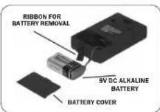
The transmitter and receiver are each operated by a 9V alkaline battery. Before use, install a battery as shown. Make certain the battery is fully seated in its compartment so the cover slides in place easily. Battery life with alkaline batteries is approximately 8 hours of operating time. The receiver also features an external jack for connecting a 9V DC power supply (not included).
If there is a "dead spot" in a room, try a slight change of position or try changing frequencies. Each unit provides two selectable transmitting frequencies.
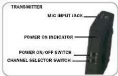
1) Switch the Frequency Selector Switch to the desired channel (A or B).
2) Belt clip on the back of the unit clips the transmitter onto a belt or the transmitter simply can be put into a pocket.
31 Plug the microphone into the Mic Input Jack.
4) The microphone can be clipped to a necktie or other clothing, using the supplied clip. The lapel mis should be placed under the chin, as close to the center of the body as possible
5) Slide the power ON/OFF switch to the ON position (the LED indicator light will illuminate).
HELPFUL HINTS
A) If the selected channel is noisy, switch both the transmitter and receiver to the other channel.
B) Low ceiling fluorescent lighting, overhead telephone lines, or close proximity to metal fences can all cause static. If this occurs, try a slight change of position and/or try changing frequencies.
C: When the battery voltage drops below 6V, the LED indicator will go out. This means you need a new battery.
D) Be sure to turn off the power whenever the units are not in use, and remove the batteries if the units will be out of service for a long time. NOTE: There are no user-adjustable parts inside the transmitter or receiver Do not attempt to open or make any adjustments. E) Cellular telephones cause interference. Ask your audience to turn off their cell phones.
BELT CLIP
A detachable belt clip is included for convenience. Slide the tapered end of the belt clip into the grooved area located on the back of the unit until it clicks into place.
PROBLEM SOLVING
FEEDBACK
Feedback is the howl or scroch often heard in sound reinforcement systems. It is caused by sound from the loudspeaker returning to the microphone. Ampivox systems utilize proven acoustical principles to minimize this; however, there is no way to completely eliminate feedback under conditions of high amplification. If feedback occurs check the following:
- User's hand covering the head of the microphone. (Hold microphone under head slots.)
- Sound can easily re-enter microphone. Keep loudspeaker turned toward audience. Note: sound can be reflected from a hard surface back through the microphone. (Tum speaker.)
- User holding microphone in a reflecting position. (Turn microphone.)
- Volume setting too high. (Reduce microphone channel volume; compensate by speaking louder or closer to the microphone.)
NO SOUND
Make sure amplifier POWER switch is turned on and rod LED is lit. If switch is on and LED is not lit, check to see that batteries are properly connected and at full charge. If using optional power adapter, check to see that front panel connector is properly seated, and verify that power source is live.
IF YOU HAVE ANY QUESTIONS OR PROBLEMS PLEASE CALL OUR CUSTOMER SERVICE DEPARTMENT AT 1-800-267-5486

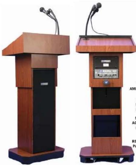
EXECUTIVE ADJUSTABLE SOUND COLUMN LECTERN S505A / SW505A
natural_image
Two wooden podiums with speakers and audio equipment, no visible text or symbols on the devices themselves.NEED HELP?
CALL 800-267-5486
OR 847-498-9000
EMAIL:
CUSTOMERSERVICE®
AMPLI.COM
NEVER RUN OUT OF POWER GUARANTEE!
AMPLIFIER POWER SOURCES (SOLD SEPARATELY)
10 D-CELL ALKALINE BATTERIES FOR UP TO 200 HOURS TALK TIME
S1460 INTERNATIONAL AC ADAPTER/RECHARGER (110/240V; 50/60HZ)
S1465 NICAD
RECHARGEABLE BATTERY
PACK (REQUIRES S1460).
Thank you for choosing the S505A and SW505A Executive Adjustable Lectern from AmpilVox Portable Sound Systems. Our system combines flexibility with functionality. Please refer to this user guide as you enjoy the unique capabilities of another quality product from AmpilVox Portable Sound Systems. As always, you can reach us at 800-267-5486, or at 847-489-9000, Monday - Friday 8am - 6pm CST.
USER GUIDE
TABLE OF CONTENTS 1
ASSEMBLY OF LECTERN (NO TOOL ASSEMBLY).2
CONTROL PANEL 3
WIRELESS MIC SETUP ....4
PROBLEM SOLVING ....4

EXTEND YOUR VOICE WITH
AMPLiVox®
PORTABLE SOUND SYSTEMS

WHAT'S IN THE BOX?
S505A
S805A Multimedia Stereo Amplifier
Dynamic XLR Microphone
15 foot ALR mic cable
Flexible Goosenheck with Shock Mount Isolated Min Helios
2 Built in Speakers
4 Neural Knobs/screws for
Reading Table 1' knob, 1' long
4 Neural Knobs for Base 2 ^st long
Speaker:Grille Cover
SW505A
SW805A Multimedia Stereo Amplifier
v/Internal Wireless Receiver Derevis XLP Microphone
Дуанию XEA Micropione
15 TDDI ALR MIC cable Flexible Capacitor
Flexible Goodschool with School Mount Isolated Mic Holter
Wireless Mic and Transmitt
2 Built in Speakers
4 Neural Knobs/screws for
Reading Table 1 Knob, 1 long
4 Neutral Risks for Base 2 long Enquest Stille Count
Speaker: Grill Cover
NO TOOL ASSEMBLY OF LECTERN
Please read all instructions first and then follow the steps below:
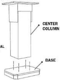
BASE ASSEMBLY
- Remove center column and shroud assembly from the shipping carton and place as shipped (face down) on the floor or on a suitable sturdy table.
- Remove and unpack the base from the shipping carton.
- Assemble the base to the column as shown in FIGURE 1 by using four of the 2 inch long neural knob screws supplied with the lectem.
TIP: Do not completely tighten each screw as you place it through the base and into the column. Wait until all four screws have been put into the proper position and then tighten them up.
FIGURE 1 FRONT VIEW
- Tum the base and column assembly upright. If assembled on a table place the unit upright on the floor.
READING TABLE ASSEMBLY
- Remove and unpack the lectern reading table.
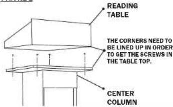
- Attach the table to the top of the column. See FIGURE 2. This is accomplished by placing the table top on the column base and lining up the corners.
TIP: the corners need to be lined up in order to get the screws in the table top. - Fasten the reading table to the column with the 4.1 inch long neural knob screws supplied. The knob screw goes up into the reading table through the 4 holes in the column (see FIGURE 2).
FIGURE 2
SPEAKER COVER / AMPLIFIER
-
Remove and unpack the speaker cover.
-
Attach the speaker cover to the front of the shroud by pushing the plastic posts in each corner of the cover into the rubber receptacles in the front of the shroud. See figure 4 and 5.
-
Flush mount amplifier is built-in.
-
For an optional speaker installation (S1201) make sure the speaker connection cable is routed through the proper notch in the back face of the amplifier pocket of the shroud so that the table will not pinch the cable when mounted. See FIGURE 3.
- (SW505A) Make sure the antenna cable is also routed through the notch in the same manner.
- SW505A ONLY - Insert the small (2.5mm) plug into the amplifier jack labeled 'Antenna.'
- See the amplifier operation manual for further instructions regarding operation of the sound system.
OPERATION OF ADJUSTABLE LECTERN
This lectern adjusts from 39 inches to 45 inches measured from the Amplifier side. To adjust the lectern height:
1. With one hand flat in the center of the table holding it down loosen the adjustable height knob with the other hand.
2. You may extend the lectern up to its maximum height of 45 inches.
3. To lower the lectern, lightly press down on the reading table until the desired height is reached and retighten the height-locking knob.
TIP: The knob locks at any height by tightening it. The lectem will adjust from 45 inches down to 39 inches when measured from the amplifier side.
ASSEMBLY OF FLEXIBLE GOOSENECK: (FIGURE 3)
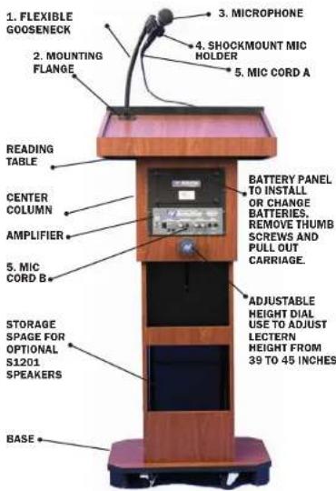
To install the 1. GOOSENECK onto the 2. MOUNTING FLANGE located by the far left corner of the desktop reading surface, first turn the neck piece clockwise onto the mount. Next install the microphone holder (U shaped piece) onto the end of the goosenck by turning it clockwise onto the top of the neck. You can then slide the 3. MICROPHONE into the 4. MICROPHONE HOLDER as shown.
The 5. MIC CORD has a plug with three small holes in one end. A for connecting with the microphone, and a 14 in. make plug on the other end, B for connecting with the unit on the control panel. Connect the end with the three holes to the base of the microphone, and plug the male 14 in. end of the microphone cord into the jack labeled DYNAMIC. The microphone has an ON/OFF switch. It should always be in the OFF position until the main power is ON and you are ready to speak.
TO INSTALL OR REPLACE BATTERIES
Remove all cables and plugs from amplifier. Unscrew the thumb screws. Pull carriage out to install new batteries. Insert 10 new Alkaline "D" cell batteries, be sure to observe polarity, or replace with S1465 NICad battery pack. Carefully replace battery carriage. Resttach battery door.
TIP: Do not mix battery types or attempt to recharge alkaline batteries - equipment damage, safety hazard or fire could result.
OPTIONAL POWER SUPPLY INSTALLATION
Optional Power Supplies may be substituted. Model S1460, International AC Adapter/Recharger (110/220V, 50/60Hz). Model S1452, 12 Volt DC adapter (automotive cigarette lighter plug-in). S1485 NICad Battery Pack.
FIGURE 3
TO OPERATE:
Plug microphone into DYNAMIC Microphone jack.
Plug straight end of 12' speaker cable into built in speaker jack and right angle end into left SPEAKER jack on amplifier.
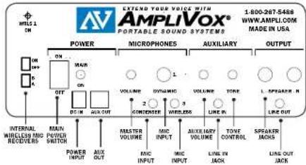
Tum Amplifier on switch is located on the front of the amplifier. The red light will go on, showing that power is available. Rotate VOLUME control knob to obtain desired loudness level throughout the coverage area.
ON-OFF
When switch is in the ON position, the red light will be on.
DC IN
Connection for optional adapter:
S1460 Universal AC Adapter (110/220V.
50/60Hz)
S1465. Nicad Battery Pack it requires S1460 AC
Adapter/recharger)
AUX OUT
Power source for 12 to 15V DC accessories.
MICROPHONE VOLUME
Controls the volume level of the microphones, including the wireless microphones.
MICROPHONE INPUTS
There are three microphone inputs, which can be used simultaneously:
DYNAMIC - for standard dynamic microphones 1/4 in.
CONDENSER - for electret or condenser microphones, which require phantom power (supplied from the amplifier) 3.5mm
WIRELESS - accepts output from an external wireless microphone receiver
AUXILIARY
The LINE IN provision is for connecting an external audio source such as a CD player, tape player, MP3 player or computer sound card. This input also serves as a provision for connecting additional wireless microphone receivers, audio mixers and other line level audio sources.
Separate VOLUME and TONE control knobs allow flexibility in controlling the sound quality as well as balancing the auxiliary source with the microphones.
OUTPUT
The LINE OUT provision may be used for connecting to an input on a recording device, such as a computer sound card, MP3 recorder, tape recorder, or similar device. The LINE OUT can also be used for a number of other applications, such as connecting to a house system, or connecting to one of our wireless speaker transmitters, for example.
INTERNAL SPEAKERS
The internal speakers are wired for stereo, LEFT and RIGHT channel information is reproduced by the appropriate speaker inside the unit.
EXTERNAL SPEAKERS
Two separately amplified speaker jacks allow you to use one or two S1201, S1290, or any of our horn speakers for additional sound power. Note: when using a stereo AUX source with a single speaker, only one of the stereo channels will be heard. However, all MIC inputs are heard equally on both channels.
INTERNAL WIRELESS MICROPHONE RECEIVER *SW Model only* Power 'ON' and 'OFF'; Frequency 'A' and 'B' switches. Frequency should match wireless transmitter. The red light above these switches will come on when the wireless microphone receiver is active.
S505A & SW505A CONTROL PANEL
- "A" Channel "B" Channel
- T6: 171.105 MHz T7: 171.845 MHz
- RF INTERFERENCE
- POWER SOURCE
- HELPFUL HINTS
- BELT CLIP
- PROBLEM SOLVING
- FEEDBACK
- NO SOUND
- USER GUIDE
- WHAT'S IN THE BOX?
- S505A
- SW505A
- NO TOOL ASSEMBLY OF LECTERN
- BASE ASSEMBLY
- READING TABLE ASSEMBLY
- SPEAKER COVER / AMPLIFIER
- OPERATION OF ADJUSTABLE LECTERN
- ASSEMBLY OF FLEXIBLE GOOSENECK: (FIGURE 3)
- TO INSTALL OR REPLACE BATTERIES
- OPTIONAL POWER SUPPLY INSTALLATION
- TO OPERATE:
- ON-OFF
- DC IN
- AUX OUT
- MICROPHONE VOLUME
- MICROPHONE INPUTS
- AUXILIARY
- OUTPUT
- INTERNAL SPEAKERS
- EXTERNAL SPEAKERS
Brand : AmpliVox
Model : Executive SW505A
Category : Amplifier