
VTA8311AB - Sound alarm Dahua Technology - Free user manual and instructions
Find the device manual for free VTA8311AB Dahua Technology in PDF.


| Brand | Dahua Technology |
| Model | VTA8311AB |
| Product Type | Sound Alarm (Siren) |
| Dimensions (W x H x D) | Approx. 120 x 120 x 50 mm |
| Weight | Approx. 250 g |
| Power Supply | DC 12V or AC 24V |
| Current Consumption | Max 500 mA |
| Sound Output | Up to 105 dB at 1 m |
| Sound Types | Continuous, pulsed, or custom patterns |
| Trigger Input | NC/NO dry contact |
| Operating Temperature | -10°C to +50°C |
| Enclosure Rating | IP65 (weatherproof) |
| Material | ABS plastic with UV protection |
| Mounting | Wall or ceiling mount (bracket included) |
| Certifications | CE, FCC, RoHS |
| Warranty | 2 years |
| Cleaning | Wipe with a dry soft cloth; avoid solvents |
| Safety | Install per local electrical codes; disconnect power before servicing |
| Spare Parts | Not user-serviceable; contact Dahua support for replacements |
Frequently Asked Questions - VTA8311AB Dahua Technology
User questions about VTA8311AB Dahua Technology
0 question about this device. Answer the ones you know or ask your own.
Ask a new question about this device
Download the instructions for your Sound alarm in PDF format for free! Find your manual VTA8311AB - Dahua Technology and take your electronic device back in hand. On this page are published all the documents necessary for the use of your device. VTA8311AB by Dahua Technology.
USER MANUAL VTA8311AB Dahua Technology
Emergency Phone Terminal
User's Manual

natural_image
Abstract geometric composition with gray and red color blocks (no text or symbols)Foreword
General
This manual introduces the installation, functions and operations of the emergency phone terminal (hereinafter referred to as "the device"). Read carefully before using the device, and keep the manual safe for future reference.
Models
The following signal words might appear in the manual.
| Signal Words Meaning | |
 DANGER DANGER | Indicates a high potential hazard which, if not avoided, will result in death or serious injury. |
 WARNING WARNING | Indicates a medium or low potential hazard which, if not avoided, could result in slight or moderate injury. |
 CAUTION CAUTION | Indicates a potential risk which, if not avoided, could result in property damage, data loss, lower performance, or unpredictable result. |
 PS PS | Provides methods to help you solve a problem or save you time. |
 | Provides additional information as the emphasis and supplement to the text. |
Revision History
| Version | Revision Content | Release Time |
| V1.0.0 | First release. | June 2022 |
Privacy Protection Notice
As the device user or data control panel, you might collect the personal data of others such as their face, fingerprints, and license plate number. You need to be in compliance with your local privacy protection laws and regulations to protect the legitimate rights and interests of other people by implementing measures which include but are not limited: Providing clear and visible identification to inform people of the existence of the surveillance area and provide required contact information.
About the Manual
- The manual is for reference only. Slight differences might be found between the manual and the product.
- We are not liable for losses incurred due to operating the product in ways that are not in compliance with the manual.
- The manual will be updated according to the latest laws and regulations of related jurisdictions.
For detailed information, see the paper user's manual, use our CD-ROM, scan the QR code or visit our official website. The manual is for reference only. Slight differences might be found between the electronic version and the paper version.
- All designs and software are subject to change without prior written notice. Product updates might result in some differences appearing between the actual product and the manual. Please contact customer service for the latest program and supplementary documentation.
- There might be errors in the print or deviations in the description of the functions, operations and technical data. If there is any doubt or dispute, we reserve the right of final explanation.
- Upgrade the reader software or try other mainstream reader software if the manual (in PDF format) cannot be opened.
- All trademarks, registered trademarks and company names in the manual are properties of their respective owners.
- Please visit our website, contact the supplier or customer service if any problems occur while using the device.
- If there is any uncertainty or controversy, we reserve the right of final explanation.
Important Safeguards and Warnings
This section introduces content covering the proper handling of the device, hazard prevention, and prevention of property damage. Read carefully before using the device, and comply with the guidelines when using it.
Transportation Requirements

- Transport the device under allowed humidity and temperature conditions.
- Pack the device with packaging provided by its manufacturer or packaging of the same quality before transporting it.
- Do not place heavy stress on the device, violently vibrate or immerse it in liquid during transportation.
Storage Requirements

- Store the device under allowed humidity and temperature conditions.
- Do not place the device in a damp, dusty or extremely hot or cold site that has strong electromagnetic radiation.
- Do not place heavy stress on the device, violently vibrate or immerse it in liquid during storage.
Operation Requirements

- Make sure that the power supply is correct before use.
- Do not unplug the power cord on the side of the device while the adapter is powered on.
- Operate the device within the rated range of power input and output.
- Transport, use and store the device under allowed humidity and temperature conditions.
- Do not drop or splash liquid onto the device, and make sure that there is no object filled with liquid on the device to prevent liquid from flowing into it.
- Do not disassemble the device.
Installation Requirements

WARNING
- Do not connect the power adapter to the device while the adapter is powered on.
- Strictly comply with the local electric safety code and standards. Make sure the ambient voltage is stable and meets the power supply requirements of the device.
- Do not connect the device to two or more kinds of power supplies, to avoid damage to the device.

- Personnel working at heights must take all necessary measures to ensure personal safety including wearing a helmet and safety belts.
- Do not place the device in a place exposed to sunlight or near heat sources.
- Keep the device away from dampness, dust, and soot.
- The power supply must conform to the requirements of ES1 in IEC 62368-1 standard and be no higher than PS2. Please note that the power supply requirements are subject to the device label.
- The device is a class I electrical appliance. Make sure that the power supply of the device is connected to a power socket with protective earthing.
- Operating temperature: -30^ to +65^ ( -22^ to +149^ ).
- When installing the device, make sure that the power plug and appliance coupler can be easily reached to cut off power.
- Prevent liquid from dripping or splashing on the device. Do not put any objects filled with liquid, such as a vase, on top of the device.
Maintenance Requirements

WARNING
Power off the device before maintenance.
Table of Contents
Foreword ....
Important Safeguards and Warnings....III
1 Overview....1
1.1 Introduction ...... 1
1.2 Functions....1
2 Unpack and Check....2
3 Structure .... 3
3.1 Mainboard Ports .... 3
3.2 Front Panel....5
3.3 Rear Panel....6
4 Networking....8
5 Installation and Wiring....9
5.1 Dimensions....9
5.2 Installation....9
5.2.1 Building the Foundation 9
5.2.2 Pole Mount....11
5.3 Wiring 13
5.3.1 External AC Power Port Connection....13
5.3.2 Network Connection ....15
5.3.3 Dot-matrix Display Connection ....17
5.3.4 Local Alarm Input Cable Connection ....17
5.3.5 Local Alarm Output Cable Connection....18
6 Web Operations....19
6.1 Starting the Device....19
6.1.1 Initializing the Device....19
6.1.2 Logging into Webpage 19
6.1.3 Resetting Password ....20
6.2 General....21
6.2.1 Call Linkage 21
6.2.2 PSTN 22
6.2.3 Zone....23
6.2.3.1 Zone Configuration....23
6.2.3.2 Protection Zone Management ....24
6.2.4 Video....24
6.2.4.1 Encode....24
6.2.4.2 Image 26
6.2.4.3 Overlay 27
6.2.4.3.1 Configuring Channel Title....27
6.2.4.3.2 Configuring Time Title....28
6.2.4.3.3 Configuring Image Information ....28
6.2.5 Audio....29
6.2.6 Advertising 30
6.2.6.1 Configuring Advertising Resources....30
6.2.6.2 Configuring Advertising Texts....31
6.2.7 Lock....32
6.3 Network 32
6.3.1 TCP/IP....32
6.3.2 Port....34
6.3.3 2G/4G....35
6.3.4 UPnP....37
6.3.5 Register....37
6.3.6 SIP Server 38
6.3.7 FTP....39
6.3.8 Basic Services....40
6.4 System 41
6.4.1 Account....41
6.4.1.1 Adding User 42
6.4.1.2 Adding User Group 43
6.4.1.3 ONVIF User....44
6.4.2 Time....46
6.4.3 Maintenance....47
6.4.3.1 Auto Maintenance....47
6.4.3.2 Configuring Backup Settings....47
6.4.3.3 Default....48
6.4.4 Update....48
6.4.5 Storage....49
6.5 System information ....49
6.5.1 Version....49
6.5.2 Legal Information....49
6.6 Logs 49
6.6.1 Viewing Call History....49
6.6.2 Viewing Logs....49
6.6.3 Viewing Remote Logs....50
6.7 Security....50
6.7.1 Security Status ....50
6.7.2 System Service....52
6.7.2.1 802.1x....52
6.7.2.2 HTTPS....53
6.7.3 Attack Defense....54
6.7.3.1 Firewall....54
6.7.3.2 Account Lockout....56
6.7.3.3 Anti-DoS Attack....56
6.7.4 CA Certificate....57
6.7.4.1 Installing Device Certificate ....57
6.7.4.1.1 Creating Certificate 57
6.7.4.1.2 Applying for and Importing CA Certificate 58
6.7.4.1.3 Installing Existing Certificate....59
6.7.4.2 Installing Trusted CA Certificate 60
6.7.5 Video Encryption....61
6.8 Record....62
6.9 Picture 62
Appendix 1 Cybersecurity Recommendations ....64
1 Overview
1.1 Introduction
Specially built for emergencies, the VTA8 Series Emergency Phone Terminal is an emergency device that contacts the alarm receiving center by just the press of a button. It has a 2-MP HD camera, high-sensitivity microphone, dual network ports and an optional 4G module integrated into its design. Highly intuitive, it features functions such as two-way audio and voice broadcast, and for select models, the device can remotely open its own compartments.
Convenient and easy to use, the device has a built-in PSTN module that connects to the telephone line and links to the alarm receiving center, allowing you to make calls directly from the device. It is also compatible with external speed domes, bullet cameras and LED displays, and is applicable for use in schools, public squares, transit stations, scenic areas, hospitals, and more.
1.2 Functions
The device can be connected to the ICC platform, and configured on the webpage.
• Supports one-press alarm.
- The platform can make videos, take snapshots and monitor the alarm terminal.
- The platform can broadcast to multiple alarm terminals simultaneously.
- Swipe card.
- Extend with IPC, speed dome and snapshot camera.
- Dot matrix display can be connected to show information.
- The 10-inch built-in LCD display can play advertisements and provide guidance information (only applicable on select models).
- Remote unlock (only applicable on select models).
2 Unpack and Check
When you receive the device, check the items in your package against the following checking list. If any of the items are missing or damaged, contact the local retailer or after-sales service immediately.
Table 2-1 Unpack and check
| No. | Item | Content | |
| 1 Whole package | Appearance No obvious damage. | ||
| Package | Whether there are signs of accidental impacts. | ||
| Accessory | Whether accessories are complete. | ||
| 2 Casing | Appearance No obvious damage. | ||
| Data cables, power cables, fan cables, and main board | No loose connections.Contact after-sales serviceimmediately if any of the cables or lines are loose. | ||
| 3 Quick start guide — | |||
3 Structure
3.1 Mainboard Ports
Figure 3-1 Mainboard ports
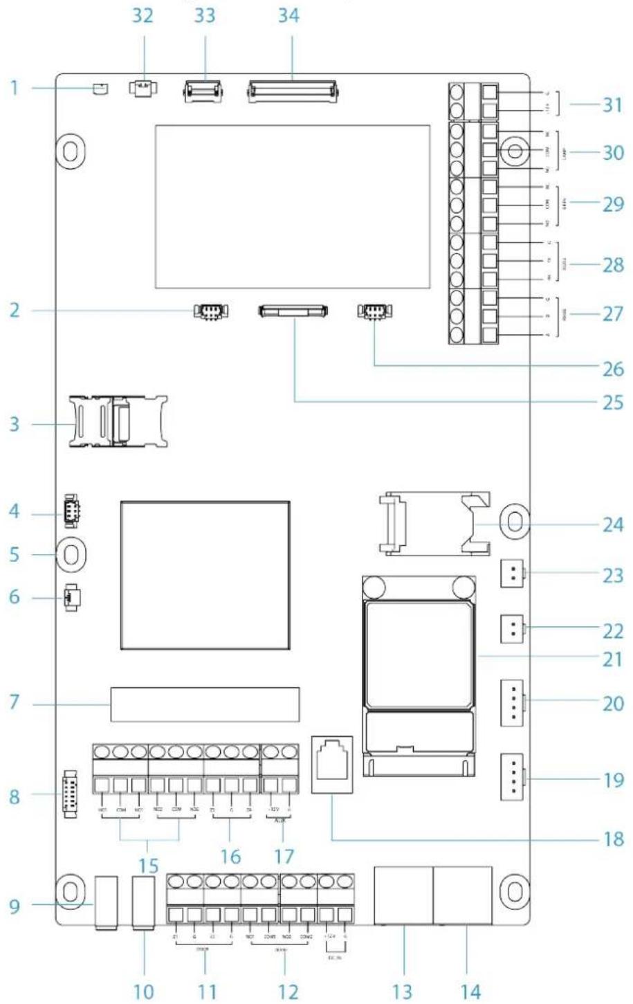
Table 3-1 Mainboard ports
| No. | Name | No. | Name | No. | Name |
| 1 | LCD temperature port | 13 | NIC2 | 25 | Sensor port |
| 2 | Illuminator module | 14 | NIC1 | 26 | Illuminator module |
| 3 | SD card slot | 15 | Alarm output | 27 | RS-485 |
| 4 | LCD heater module | 16 | Alarm input | 28 | RS-232 |
| 5 | Heater control module | 17 | Auxiliary power output port | 29 | Siren port |
| 6 | MIC port | 18 | Telephone jack | 30 | Alarm light port |
| 7 | PSTN module | 19 | Alarm button 2 | 31 | Alarm light/siren power port |
| 8 | Card swiping port | 20 | Alarm button 1 | 32 | LCD module |
| 9 | Speaker output | 21 | 4G module | 33 | Touchscreen port |
| 10 | MIC-in port | 22 | Speaker 1 | 34 | LCD display port |
| 11 | Tamper port | 23 | Speaker 2 | — | — |
| 12 | Lock control port | 24 | SIM card slot | — | — |

Alarm button 2 is currently not available.
3.2 Front Panel
Figure 3-2 Front panel
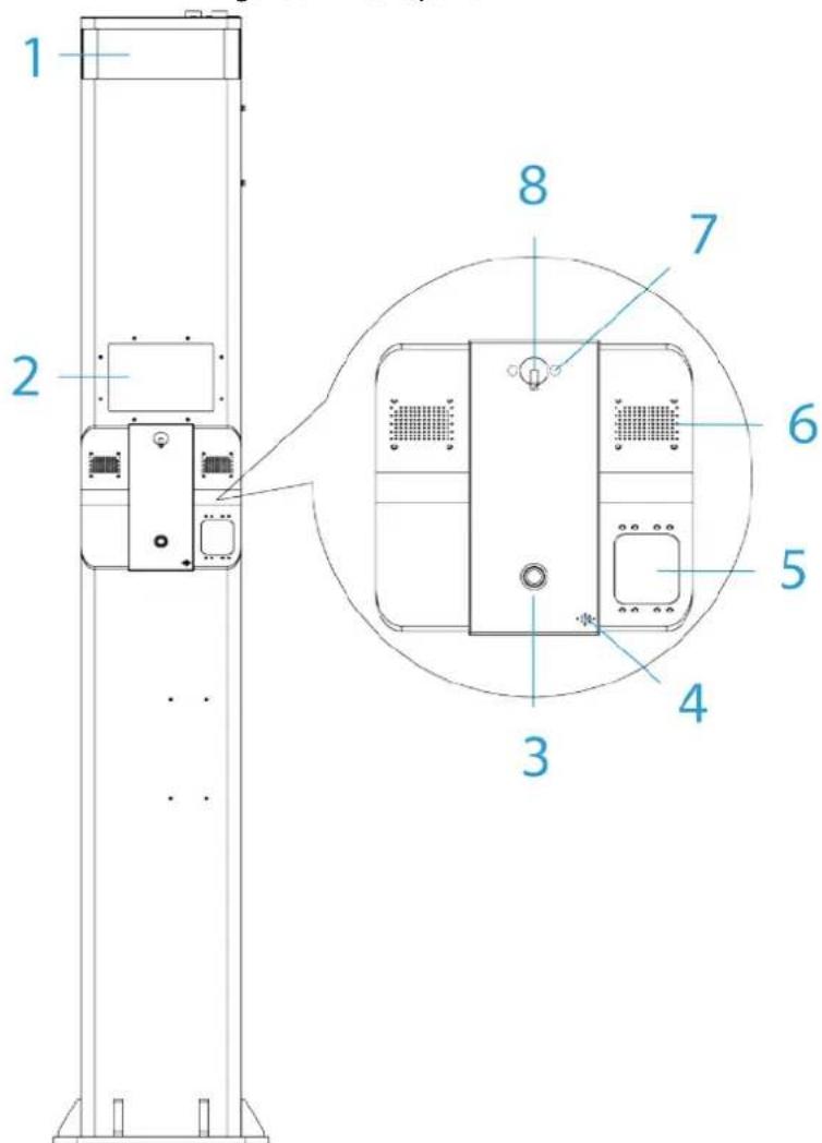
Table 3-2 Front panel description
| No. | Name Description | |
| 1 | Alarm light | Indicates an alarm was triggered.Normal: Solid on.Being called: Flashes first and then returns to the normal status. |
| 2 | LCD display screen | Plays images or videos, and shows call status. |
| 3 | Alarm button | Press the button to call the management center or the ICC platform in an emergency. |
| 4 | Microphone Audio input. | |
| 5 | Card swiping area | Supports IC card recognition. |
| 6 | Speaker Audio output. | |
| 7 | Illuminator Provides IR light for dark environments. | |
| 8 | Camera | Captures visual images in front of the alarm terminal. |
3.3 Rear Panel
There are 2 types of the device.
- Basic type: Designed with a mechanical lock.
• Electronic type: Designed with an electronic key.
Figure 3-3 Rear panel (basic)
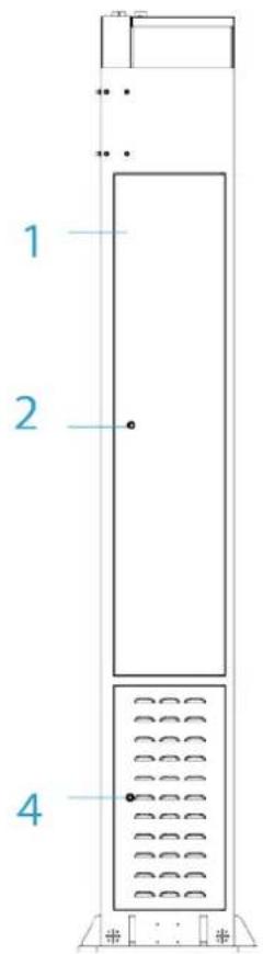
Figure 3-4 Rear panel (electronic)
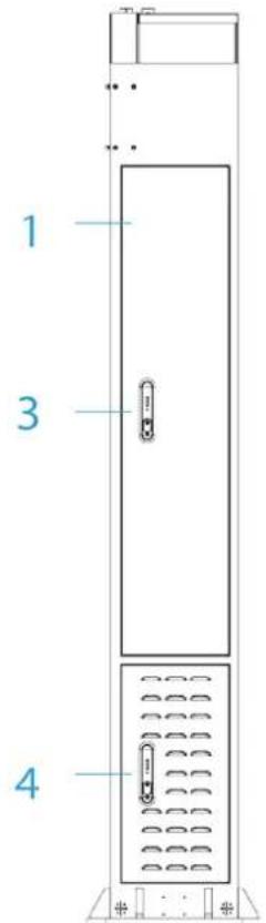
Table 3-3 Rear panel description
| No. Name Description | ||
| 1 | Maintenance compartment | Open the maintenance compartment to perform maintenance on the internal device. |
| 2 Mechanical lock Unlock with key. | ||
| 3 Electronic key | Remote unlock through the platform or web manager of the device. | |
| 4 | Tool compartment | Stores tools. |
4 Networking
Figure 4-1 Network diagram
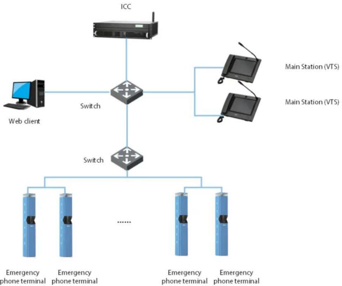
flowchart
graph TD
    A["ICC"] --> B["Switch"]
    C["Web client"] --> B
    D["Main Station (VTS)"] --> E["Switch"]
    F["Main Station (VTS)"] --> E
    B --> G["Emergency phone terminal"]
    B --> H["Emergency phone terminal"]
    E --> I["Emergency phone terminal"]
    E --> J["Emergency phone terminal"]
5 Installation and Wiring

- Do not install the device in a poor environment that has condensation, high temperatures, stains, dust, and is exposed to corrosive chemicals.
- Installation and debugging must be carried out by a professional team. Do not dismantle or repair the device without professional assistance to avoid damaging the device.
5.1 Dimensions

Before installation, make sure you know the dimensions of the pedestal and the space between the screw holes.

Each screw hole is 24 mm in diameter, so the reinforced steel bar going through the hole must be 20 mm in diameter.
![Figure 5-1 Dimensions (Unit: mm [inch]) 380.0 [14.96] Ø24.0 [Ø0.94] 450.0 [17.71] 380.0 [14.96] 460.0 [18.11]](/content/2026/05/1059530/images/c14fa14feab17f45ab010f5372a6e1fe8ecc7a15346d1b04b685be4b9504f3be.jpg)
5.2 Installation
5.2.1 Building the Foundation

We recommend you follow the industry standards when installing the device, such as digging trenches, burying pipes, laying cables, and performing insulation tests.
Step 1 Select the installation location of the device according to the construction drawings.

While you are making your selection, we recommend considering conditions such as wiring, drainage and ventilation.
Step 2 Dig a groove.
Step 3 Embed pipes.
Step 4 Build the foundation.
1) At the bottom of the foundation, pave about 100 mm high gravels.
Figure 5-2 Build the foundation
![100.0 [3.15] Nut Reinforced Steel Bar 1200.0 [47.24] Concrete (C25) Gravel 100.0 [3.94]](/content/2026/05/1059530/images/4fc19b62ca73747bdd57a40739d4aced6f162bcaf9d1c52280ace6e9091a12f0.jpg)
2) Fill it with C25 cement. The length and the height must not be lower than 800 mm, and the width must not be lower than 1200 mm.

The length, width, and depth of the foundation must be adjusted depending on the texture of the soil, and the experience of the professionals with constructions. The measurement of 800 mm and 1200 mm is only for your reference.
Figure 5-3 Size of the foundation (Unit: mm [inch])
![800.0 [31.50] 800.0 [31.50] Concrete (C25) Installation Surface](/content/2026/05/1059530/images/e7ac043499d64b29c6ab83fa930c15c1790591df5b928beb61a548403d670ec5.jpg)
3) On C25 concrete, insert four 20 mm reinforced steel bars according to screw hole spacing.
4) Lay cables.
5) Carry out the insulation test.
6) Install the device.
Guide the 20 mm reinforced steel bars through the 4 holes on the pedestal, and then tighten and attach them with the M20 bolts.
5.2.2 Pole Mount
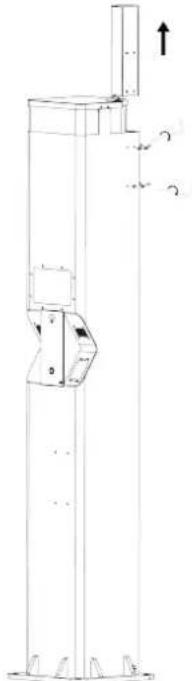
Step 1 Remove the screws with a screwdriver to take out the cylinder-shaped pole.
Figure 5-4 Take out the cylinder-shaped pole
natural_image
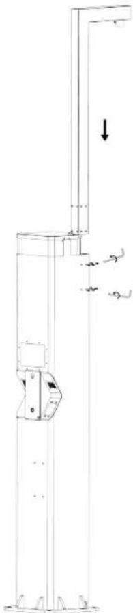
Technical line drawing of a vertical industrial structure with mounting feet and a directional arrow (no text or symbols)Step 2 Pu t in the L-shaped pole and then secure the device with the screw.
Figure 5-5 Put in the L-shaped pole
natural_image
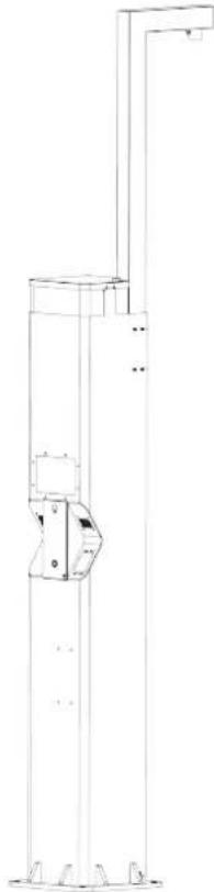
Technical line drawing of a vertical industrial structure with a downward arrow indicating force or movement (no text or symbols present)Figure 5-6 Pole mount
natural_image
Technical line drawing of a vertical industrial or mechanical device with mounting feet and a central component (no text or symbols)5.3 Wiring
Internal modules were connected to the device before it left the factory For the basic type of the device, you only need to connect external alternating current and an external network. This section uses wiring of the basic type as an example.
5.3.1 External AC Power Port Connection

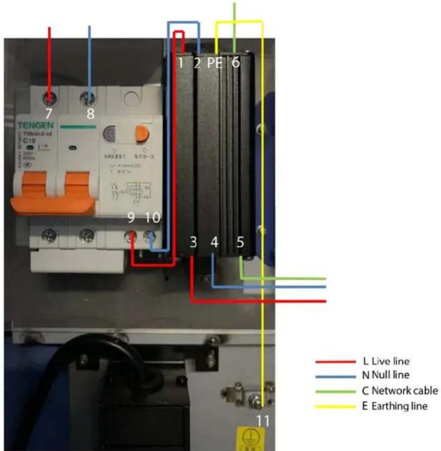
Before connecting the device, make sure that the air circuit breaker is turned off. After you finish wiring the device, turn on the air circuit breaker, and the device will be powered on.
Connect the mains electricity to the number 7 and 8. The number 11 earthing line must be connected to PE.
Figure 5-7 Connect external alternating current
5.3.2 Network Connection
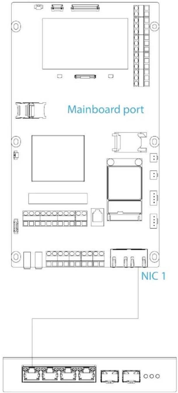
Figure 5-8 Network connection
Switch
Figure 5-9 Network input port
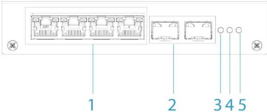
Table 5-1 Network input port description
| No. Name Description | ||
| 1 10/100/1000 | Base-T | There are four 10/100/1000 Mbps self-adaptive electrical ports. |
| 2 | 1000 Base-X | There are two 1000 Mbps optical ports. |
| 3 | Optical fiber indicator | — |
| 4 | ||
| 5 Power indicator | ||
The device supports fiber connection.
- Wired connection: Through the RJ-45 Ethernet port (number 5) in Figure 5-7, connect the external network. Then lead a network cable from the RJ-45 Ethernet port (number 6) in Figure 5-7 to gigabit port (number 1) in Figure 5-9.
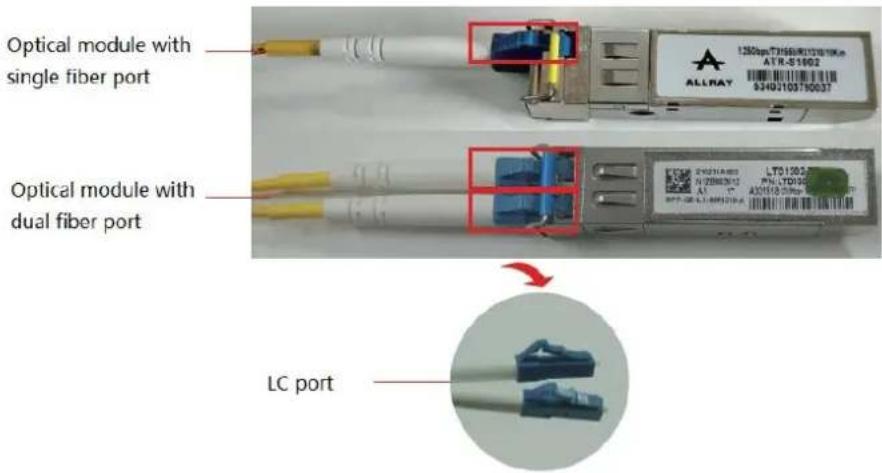
- Fiber connection: If an optical fiber is laid, connect the external network to the optical fiber port in Figure 5-10.

The receiving and sending of the working wave bands and bandwidth of optical modules at both ends of the optical fiber must be matched. Otherwise, the network will not function correctly.
Figure 5-10 Single fiber or dual fiber optical module port
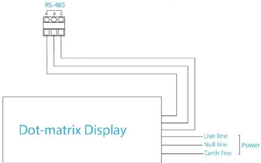
5.3.3 Dot-matrix Display Connection
Figure 5-11 Connect dot-matrix display
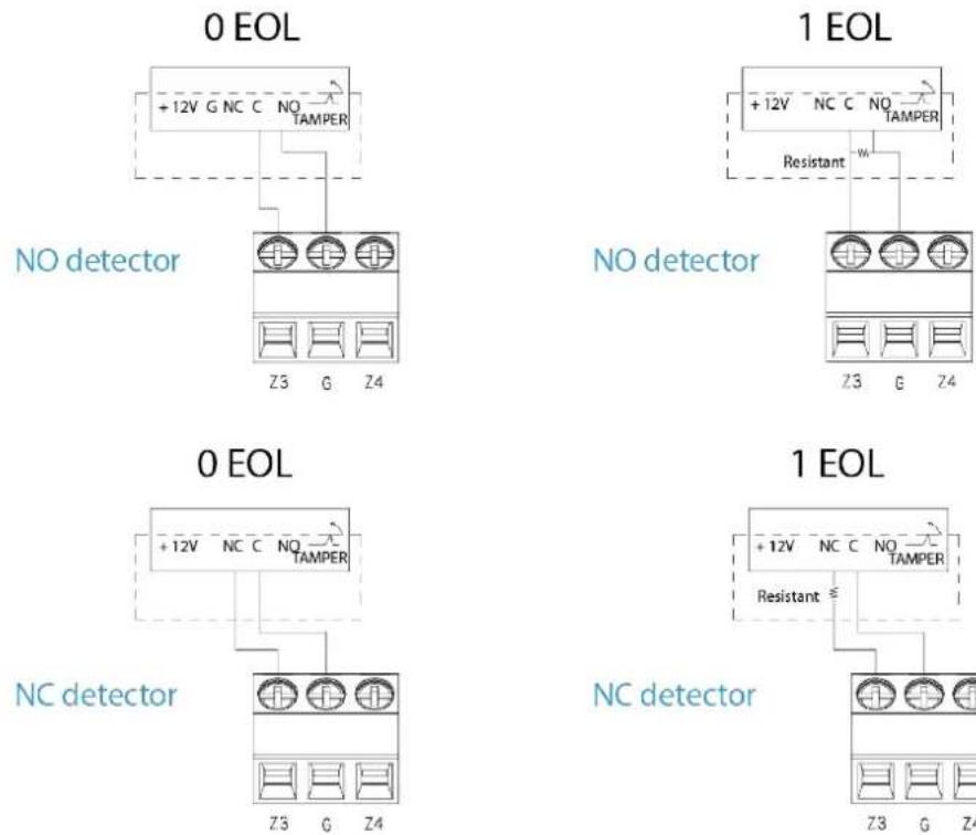
5.3.4 Local Alarm Input Cable Connection
The device supports 0 EOL and 1 EOL.
Figure 5-12 Detector wiring
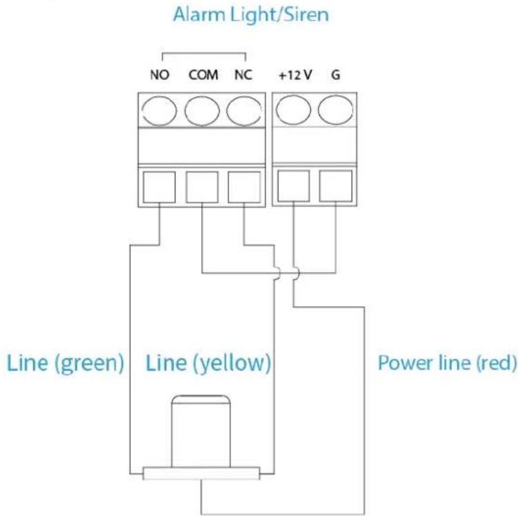
5.3.5 Local Alarm Output Cable Connection
Figure 5-13 Local alarm output cable connection
flowchart
graph TD
    A["Alarm Light/Siren"] --> B["NO"]
    A --> C["COM"]
    A --> D["NC"]
    A --> E["+12V"]
    A --> F["G"]
    B --> G["Line (green)"]
    C --> H["Line (yellow)"]
    D --> I["Power line (red)"]
    E --> J["Line (green)"]
    F --> K["Line (yellow)"]
    G --> L["Line (green)"]
    H --> M["Line (yellow)"]
    I --> N["Line (green)"]
    J --> O["Line (yellow)"]
    K --> P["Line (green)"]

• Power line: Positive (public).
- Line (yellow): Negative. When the yellow line is connected, the alarm light will be solid on.
- Line (green): Negative. When the green line is connected, the alarm light will flash.
6 Web Operations
This section introduces the parameters of the device and how to configure them on the webpage.

Some operations of the device are available on the platform. For platform operations, see the corresponding user's manual of the platform.
6.1 Starting the Device
6.1.1 Initializing the Device
Background Information
For the first-time use after the device is restored to factory defaults, you need to set the login password for admin account. You can also reserve an email address to reset password when you forget it.

- For your device safety, keep your login password of admin well after the initialization, and change the password regularly.
- The default IP address of LAN1 is 192.168.1.108, LAN2 is 192.168.2.108.
Procedure
Step 1 Open the browser, enter the default IP address of the device, and then press the Enter key.
Step 2 Read Software License Agreement and Privacy Policy, select I have read and agree to the terms of the Software License Agreement and Privacy Policy, and then click Next.
Step 3 Select language, and then click Next.
Step 4 Set date format, time zone, and system time, and then click Next.

Click Sync PC to synchronize the system time with the PC.
Step 5 Enter and confirm the new password, set email address, and then click Next.

The reserved email address is used to receive security code for resetting password.
Step 6 Click Completed.
The system will prompt you that the initialization is successful, and then login page will be displayed.
6.1.2 Logging in to Webpage
Prerequisite
Make sure that the local computer and the device are on the same network segment.
Procedure
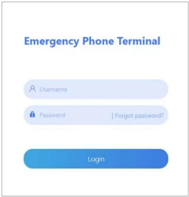
Step 1 Enter the device IP address in the address bar of the browser, and then press Enter.
Step 2 Enter username and password, and then click Login.
Figure 6-1 Login
6.1.3 Resetting Password
Prerequisites
You can set the email address for password resetting during the initialization. For details, see "6.1.1 Initializing the Device".
Procedure
Step 1 Log in to the webpage, click Forgot password?. Step 2 Click OK.
Figure 6-2 Forgot password
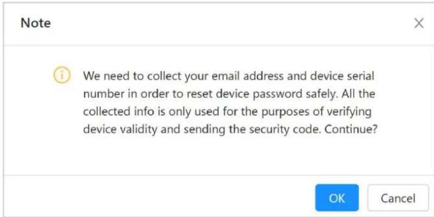
Step 3 S can the QR code according to the prompt to receive the security code.
Step 4 Enter the security code in the Security code text box, and then click Next.

Please use the security code within 24 hours after you receive it. Otherwise, it will become invalid.
Step 5 Enter and confirm the password.
The password can contain 8 to 32 non-empty characters and must have at least 2 types of the following characters: capital letters, lower-case letters, numbers, and special characters (excluding '";,: &). The confirming password should be the same as the new password. Use the password strength prompt as a guide to set a strong password.
Step 6 Click Finish.
6.2 General
On the General page, you can configure general settings, such as call linkage, PSTN, zones, videos, audios, and compartment unlock.
6.2.1 Call Linkage
Select General > Call Linkage, and then you can set call linkage actions, such as snapshot, recoding and siren.
Figure 6-3 Call linkage
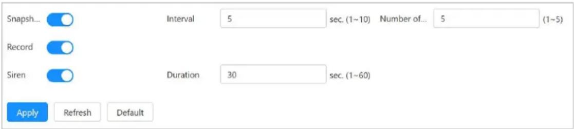
Table 6-1 Call linkage parameter descriptions
| Parameter Description | |
| Snapshot | Enabled by default.Snapshot interval ranges from 1 to 10 seconds. 5 seconds is set by default.Number of images ranges from 1 to 5. 5 is set by default. |
| Record Enabled by default. | |
| Siren | Enabled by default.Siren duration ranges from 1 to 60 seconds. 30 seconds is set by default. |
6.2.2 PSTN
Select General > PSTN, and then you can set phone number and TSD threshold, by which you can make a voice talk to the alarm receiving center or calling person.
Figure 6-4 PSTN
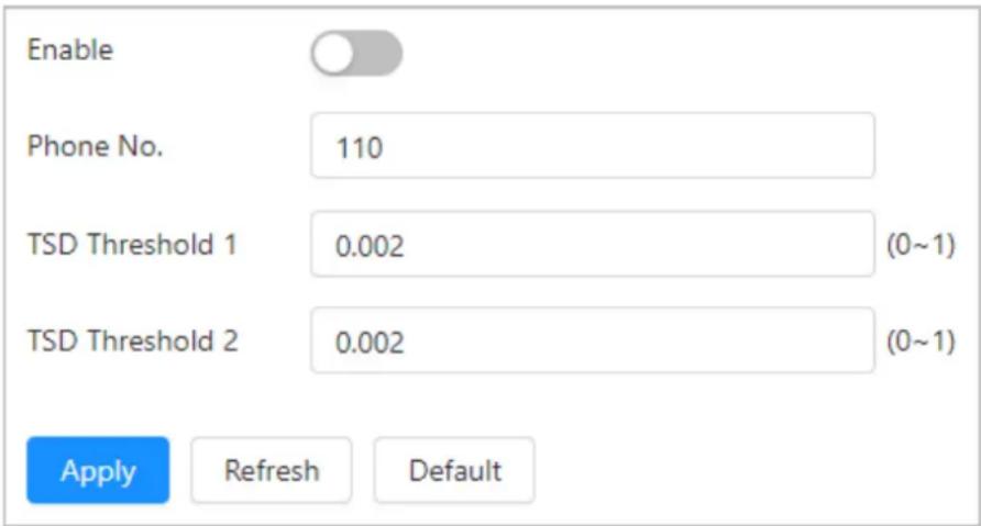
Table 6-2 Descriptions of PSTN parameters
| Parameter Description | |
| Enable Disabled by default. | |
| Phone No. | Enter alarm receiving center or personal phone number. |
| TSD threshold 1 | It is 0.002 by default, and the value ranges from 0 to 10. Configure the parameters according to the actual situation. |
| TSD threshold 2 | |
6.2.3 Zone
6.2.3.1 Zone Configuration
Select General > Zone > Zone Config, and then you can configure zone parameters and set alarm linkage actions, such as speaker, relay and siren.

Up to four zones can be configured.
Figure 6-5 Zone configuration
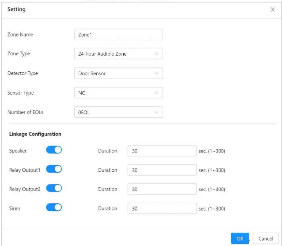
Table 6-3 Descriptions of zone parameters
| Parameter Description | |
| Zone Name Custom zone | name. |
| Zone Type | Select zone as needed.24-hour Audible Zone24-hour Silent ZoneInstant ZoneFire ZoneShielded Zone |
| Detector Type | Select detector type as needed.· Panic Button· IR· Door Detector· Water Leak Sensor· Vibration Sensor· Dual-technology (IR + Microwave) |
| Sensor Type | Select sensor type as needed.· Normally Closed· Normally Open |
| Number of EOLs | Select the number of EOL.· 0 EOL· 1 EOL |
| Speaker | Enabled by default. Speaker duration ranges from 1 to 300 seconds. 30 seconds is set by default. |
| Relay Output 1 | Enabled by default. Relay output duration ranges from 1 to 300 seconds. 30 seconds is set by default. |
| Relay Output 2 | |
| Siren | Enabled by default. Siren duration ranges from 1 to 300 seconds. 30 seconds is set by default. |
6.2.3.2 Protection Zone Management
Select General > Zone > Protection Zone Management, and then you can arm and disarm all the zones.

Up to four zones can be configured.
Figure 6-6 Protection zone management
| Arm | Disarm | ||
| Zone No. | Zone Name | Arming Status | Zone Status |
| 1 | Zone1 | Disarm | Open |
| 2 | Zone2 | Disarm | Open |
| 3 | Zone3 | Disarm | Normal |
| 4 | Zone4 | Disarm | Normal |
6.2.4 Video
6.2.4.1 Encode
Select General > Video > Encode, and then you can configure video stream parameters, such as compression, resolution, frame rate, bit rate type, bit rate, I frame interval, SVC, and watermark.
Figure 6-7 Encode
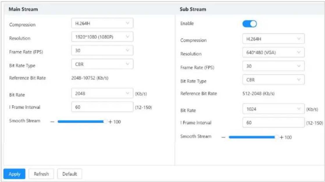
Table 6-4 Description of encode parameters
| Parameter Description | |
| Sub Stream | Click to enable sub stream, it is enabled by default. |
| Compression | Select encode mode.H.264B: Baseline profile encode mode. It requires smaller bandwidth.H.264: Main profile encode mode. Compared with H.264B, it requires smaller bandwidth.H.264H: High profile encode mode. Compared with H.264, it requires smaller bandwidth.H.265: Main profile encode mode. Compared with H.264, it requires smaller bandwidth. |
| Resolution | The resolution of the video. The higher the value is, the clearer the image will be, but the bigger the bandwidth will be required. |
| Frame Rate (FPS) | The number of frame in one second of video. The higher the value is, the clearer and smoother the video will be. |
| Bit Rate Type | The bit rate control type during video data transmission. You can select bit rate type from:CBR (Constant Bit Rate): The bit rate changes a little and keeps close to the defined bit rate value.VBR (Variable Bit Rate): The bit rate changes as monitoring scene changes.The Bit Rate Type can be only be set as CBR when Encode Mode is set as MJPEG. |
| Reference Bit Rate | The most suitable bit rate value range recommended to user according to the defined resolution and frame rate. |
| Bit Rate | This parameter can be configured only when the Bit Rate Type is set as CBR. Select bit rate value in the list according to actual condition. |
| I Frame Interval | The number of P frames between two I frames, and the I Frame Interval range changes as FPS changes. It is recommended to set I Frame Interval twice as big as FPS. |
| Smooth Stream | Drag the scroll bar or click +or - to set smooth stream value. The higher the value is, the clearer the image will be. |
6.2.4.2 Image
Select General > Video > Image, and then you can configure camera parameters according to the actual situation, including picture, exposure, backlight and white balance.
Figure 6-8 Image settings
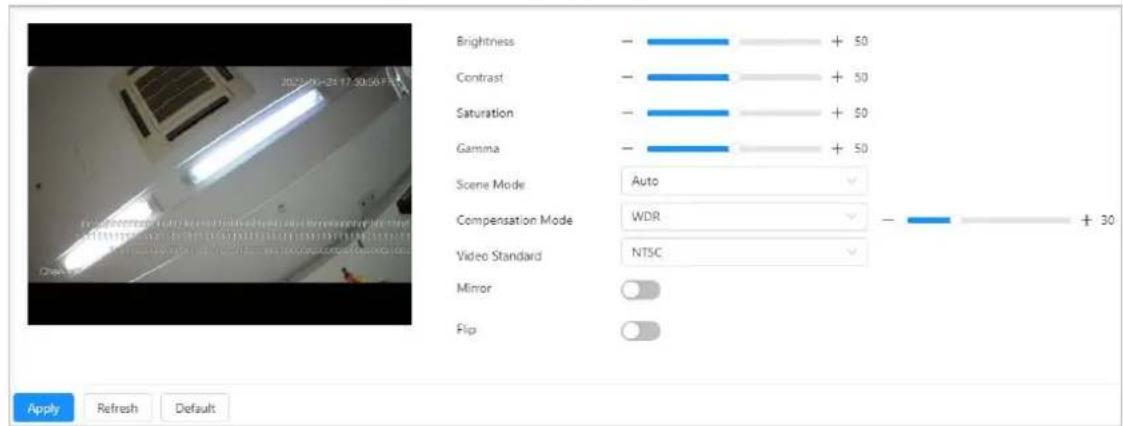
Table 6-5 Image setting parameters
| Parameters Description | |
| Brightness | Change the overall brightness of the picture. The higher the value is, the brighter the picture will be, and the smaller the darker. The picture might be hazy if the value is configured too high. |
| Contrast | Changes the contrast of the picture. The higher the value is, the more the contrast will be between bright and dark areas, and the smaller the less. If the value is set too high, the dark area would be too dark and the bright area easier to get overexposed. The picture might be gray if the value is set too small. |
| Saturation | Makes the color deeper or lighter. The higher the value is, the deeper the color will be, and the lower the lighter. This value does not affect the overall brightness of image. |
| Gamma | Changes the picture brightness and contrast in a non-linear way. The higher the value is, the brighter the picture will be, and the smaller the darker. |
| Scene Mode | Close: Close WB.Auto: The system compensates WB according to color temperature to ensure color precision.Sunny: The system compensates WB to outdoor sunny scene to ensure color precision.Night: The system compensates WB to outdoor night scene to ensure color precision. |
| Compensation Mode | Close: No backlight.BLC: Enable BLC, the camera can get clearer image of the dark areas on the target.WDR: The system dims bright areas and compensates dark areas to ensure the clarity of all the area according to the environmental lighting conditions.HLC: The system constrains bright areas and reduces halo size to dim the overall brightness. |
| Video Encoding | Select PAL or NTSC. |
| Mirror | Click , and the picture will display with left and right side reversed. |
| Flip | Click , and the picture will display with up and down side reversed. |
6.2.4.3 Overlay
Select General > Video > Overlay, and then configure overlay information, which will be displayed on the live page.
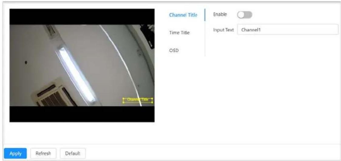
6.2.4.3.1 Configuring Channel Title
You can enable this function when you need to display channel title in the video image.
Step 1 Select General > Video > Overlay > Channel Title.
Step 2 Click to enable the channel title function.
Step 3 Configure channel title.
Step 4 Move the title box to the position that you want in the image.
Figure 6-9 Channel Title
Step 5 Click Apply.
6.2.4.3.2 Configuring Time Title
You can enable this function if you need to display time on the video image.
Step 1 Select General > Video > Overlay > Time Title.
Step 2 Click to enable time title function.
Figure 6-10 Configure time title
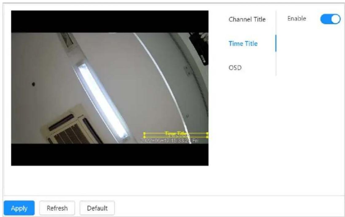
Step 3 Move the title box to the position that you want in the image.
Step 4 Click Apply.
6.2.4.3.3 Configuring Image Information
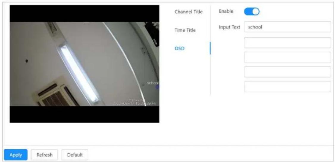
Set the OSD information content and overlay location of the captured images.
Step 1 Select General > Video > Overlay > OSD.
Step 2 Click to enable OSD function.
Step 3 Enter OSD content.
Step 4 Move the title box to the position that you want in the image.
Figure 6-11 Set OSD content
Step 5 C lick Apply.
6.2.5 Audio
Select General >Audio, and then you can configure audio parameters and alarm audio.
Figure 6-12 Audio

Table 6-6 Descriptions of audio parameters
| Parameters Description | |
| Input device | You can select audio input type from:Lineln: Requires external audio device.Mic: Not require external audio device. |
| Output device | Connect to external speaker for audio enhancement. |
| Microphone Volume | Adjusts microphone volume. |
| Speaker Volume | Adjusts speaker volume. |
6.2.6 Advertising
6.2.6.1 Configuring Advertising Resources
Built-in LCD display can show images and videos.
Step 1 Select General > Advertising > Ad Resource.
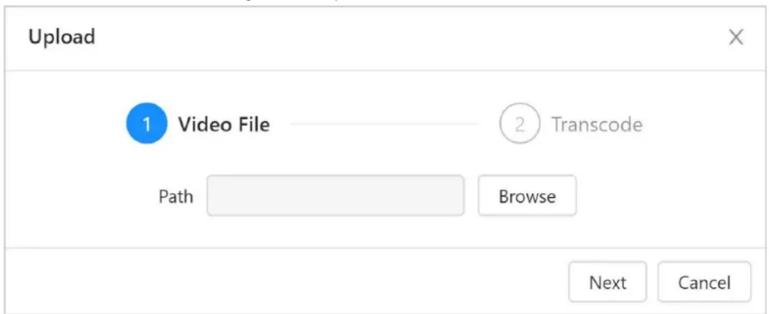
Step 2 On the Video area, click Upload to upload the video.
1) Click Browse, and then select the video file.

- You can upload video packages that are up to 20 M in size, in the avi, dav and mp4 format.
- You can upload up to 3 videos.
- Make sure that you have downloaded the plug-in to upload the video.
2) Click Next the transcode is complete.
Figure 6-13 Upload video files
Step 3 O n the Picture area, click Upload to upload the image.

- You can upload image packages that are up to 2 M in size, in the png, jpg and bmp format.
- You can upload up to 10 images.
Step 4 Set time plans for the advertising.
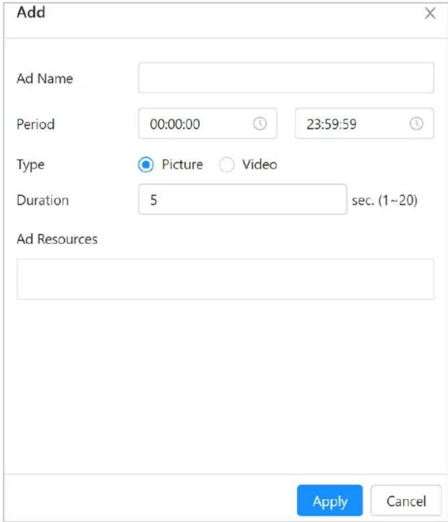
1) On the Time Plan area, click Add to add the advertising time plan.
2) Enter the advertising name.
3) Configure advertising periods.
4) Select advertising type: Picture or video.
5) Set the duration of each mage will be played.
6) Set advertising resources.
7) Click Apply.
Figure 6-14 Add time plans
Step 5 Click Apply.
6.2.6.2 Configuring Advertising Texts
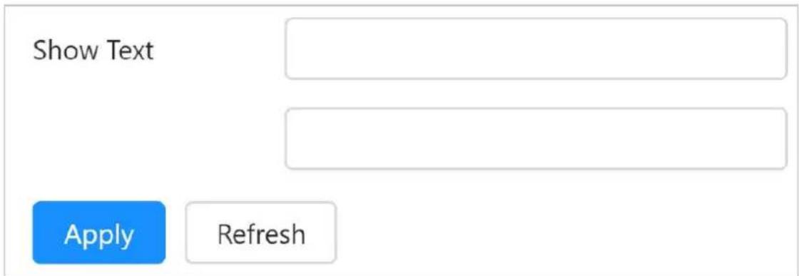
Dot-matrix screen is connected to show advertising texts from the web.
Step 1 Select General > Advertising > Dot-matrix Screen.
Step 2 Configuring advertising texts.
Figure 6-15 Configure advertising texts
Step 3 Click Apply.
6.2.7 Lock
If the device is designed with electronic lock, you can go to General >Lock to remotely unlock the upper or lower compartment.

On the webpage, you can send commands to lock or unlock the compartment, but you cannot see whether the compartment was successfully locked.
Figure 6-16 Lock settings
Upper Compartment
Unlock
Lower Compartment
Unlock
Unlock All
Table 6-7 Parameters
| Parameters Description | |
| Upper Compartment | Click Unlock to unlock the upper or lower compartment. |
| Lower Compartment | |
| Open All | Click Unlock All to unlock the upper and lower compartment at the same time. |
6.3 Network
This section introduces network configuration.
6.3.1 TCP/IP
Prerequisites
Make sure that the device is connected to the network properly.
You can configure the IP address, DNS (Domain Name System) server and more according to the network plan.
Procedure
Step 1 Select Network >TCP/IP.
Step 2 Configure the TCP/IP parameters.
Figure 6-17 TCP/IP parameters
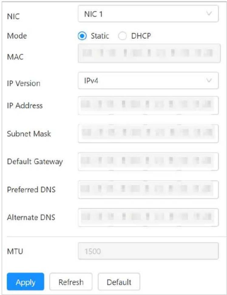
Table 6-8 Descriptions of TCP/IP parameters
| Parameters Description | |
| NIC Select | NIC1 or NIC2 according to the actual needs. |
| Mode | The mode that the device gets IP:Static: Configure IP Address, Subnet Mask, and Default Gateway manually, and then click Save, the login page with the configured IP address is displayed.DHCP (Dynamic Host Configuration Protocol): When there is DHCP server in the network, select DHCP, and the device acquires IP address automatically. |
| MAC address | Displays host MAC address. |
| IP version | Select IPv4 or IPv6. |
| IP Address | When you select Static in Mode, enter the IP address and subnet mask that you need. |
| Subnet Mask | |
| Default Gateway | IPv6 does not have subnet mask.The default gateway must be in the same network segment with the IP address. |
| Preferred DNS | IP address of the preferred and alternate DNS. |
| Alternate DNS | |
| MTU The default value is 1500. | |
Step 3 Click Apply.
6.3.2 Port
Configure the port numbers and the maximum number of users (includes web, platform client, and mobile phone client) that can access the device simultaneously.
Step 1 Select Network >Port.
Step 2 Configure port parameters.
Figure 6-18 Port
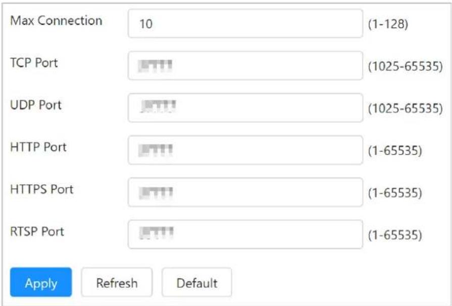
Table 6-9 Description of port parameters
| Parameters Description | |
| Max connection | The max number of users (web client, platform client or mobile phone client) that can connect to the device simultaneously, the value is 10 by default. |
| TCP port | Transmission control protocol port. The value is 37777 by default. |
| UDP port | User data packet protocol port. The value is 37778 by default. |
| HTTP port | Hyper text transfer protocol port. The value is 80 by default. |
| HTTPS port HTTPS communication port. It is 443 by default. | |
| RTSP port | Real time streaming protocol port, and the value is 554 by default. If you play live view with QuickTime, VLC or Blackberry smart phone, the following URL format is available. If you play live view with QuickTime of Safari or VLC, the following URL format is available.When the URL format requiring RTSP, you need to specify channel number and bit stream type in the URL, and also user name and password if needed.When playing live view with Blackberry smart phone, you need to turn off the audio, and then set the code mode to H.264B and resolution to CIF.URL format example:rtsp://username:@ IPAddress:port/cam/realmonitor?channel=1&subtype=0If username and password are not required for verification, the URL can be:rtsp://ip:port/cam/realmonitor?channel=1&subtype=0Username: admin, for example.Password: Your password. For example, admin.IP: Device IP. For example, 192.168.1.122.Port: Leave it if the value is 554 by default.Channel 1: Channel number, starts from 1. For example, if you are using channel 2, channel=2Subtype: The bit stream type; 0 means main stream (Subtype=0) and 1 means sub stream (Subtype=1).Example: If you require the sub stream of channel 2 from a certain device, then the URL should be:rtsp://admin:admin@192.168.1.123:554/cam/realmonitor?channel=2&subtype=1 |
Step 3 Click Apply.
6.3.3 2G/4G
Prerequisites
Make sure that 2G/4G module has been installed
Background Information
Connect the device to a 2G/4G network through the dial-up method of different operators. Then you can receive information on alarms and the status of devices on your mobile device.
Procedure
Step 1 Select Network >2G/4G.
Step 2 Click next to
Enable and Dial to enable the 2G/4G and dial function.
Figure 6-19 2G/4G setting
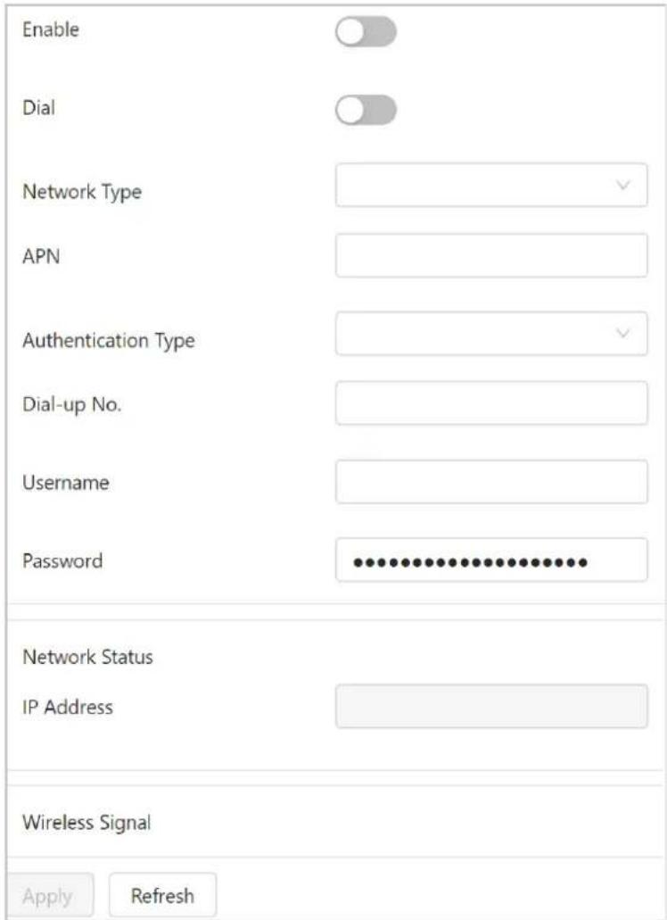
Table 6-10 Descriptions of 2G/4G parameters
| Parameters Description | |
| Network Type | Select WCDMA, Auto, EVDO, TD-SCDMA, TD-LTE and FDD-LTE. |
| APN Displays access point of communication operator. | |
| Authentication Type | When enabled, the system automatically recognize the protocol, including PAP, CHAP and NO. |
| Dial-up number | Enter the dial number provided from the communication operator. |
| User name | The device fills in the dial information automatically after recognizing 2G/4G module. |
| Password | |
| Network status | Displays network connection status. |
| IP Address | After the network connection is successful, the device will obtain and show the IP address automatically. |
| Wireless Signal | The current signal strength of the device. |
Step 3 Click Apply.
6.3.4 UPnP
Prerequisites
- Make sure the UPnP service is installed in the system.
- Log in to the router, and configure WAN IP address to set up internet connection.
- Enable UPnP in the router
- Connect your device to the LAN port of the router.
- Select Network > TCP/IP, enter the local area IP address of the router or select DHCP and acquires IP address automatically.
Background Information
UPnP (Universal Plug and Play) is a protocol that establishes mapping relation between local area and wide area networks. This function enables you to access local area device through wide area IP address.
Procedure
Step 1 Select Network > UPnP.
Step 2 Click to enable UPnP function.
Step 3 Select a service, and click to enable the service function.
Step 4 Click ☑ to modify the corresponding external port number, and then click OK.
Step 5 Click Apply.
6.3.5 Register
After you enable this function, when the device is connected into internet, it will report the current location to the specified server which acts as the transit to make it easier for the client software to access the device.
Step 1 Select Network >Register.
Step 2 Click to enable the register function.
Step 3 Enter server address, port and sub-device ID.
Figure 6-20 Register
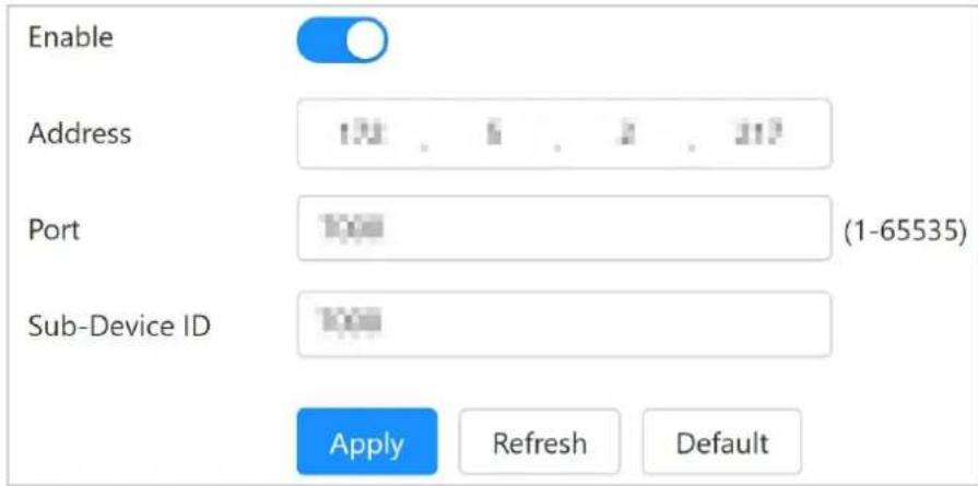
Table 6-11 Register parameters
| Parameters Description | |
| Address | The IP address or domain name of the server to be registered. |
| Port The port for registration. | |
| Sub-device ID | The custom ID for the device. |
Step 4 Click Apply.
6.3.6 SIP Server
With SIP (Session Initiation Protocol), the device can be registered to the platform. When you press the alarm button, you can have a voice talk and video to the platform.
Step 1 Select Network > SIP Server.
Step 2 Enter server IP address, port, username, password, SIP domain, and device call ID.
Figure 6-21 Configure SIP Server
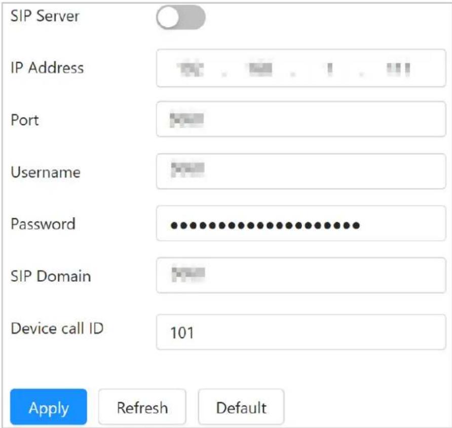
Table 6-12 Descriptions of SIP server parameters
| Parameters Description | |
| SIP Server | If the platform works as the SIP server, enter the IP address of the platform. |
| IP Address | |
| Port | If the platform works as the SIP server, enter 5080 in the SIP Sever Port. |
| User name | User name to access the SIP server. |
| Password | The password to access the SIP server. |
| SIP Domain | If the platform works as the SIP server, keep the value null. |
| Device call ID | The ID number of the device that is called. |
Step 3 Click to enable the SIP server function.
Step 4 Click Apply.
6.3.7 FTP
You can store and view the recorded videos and snapshots on the FTP server.

Select System > Storage, and then set Storage Method to FTP, after which you can store the recorded videos and snapshots
Step 1 Select Network > FTP.
Step 2 Configure the parameters.
Figure 6-22 FTP
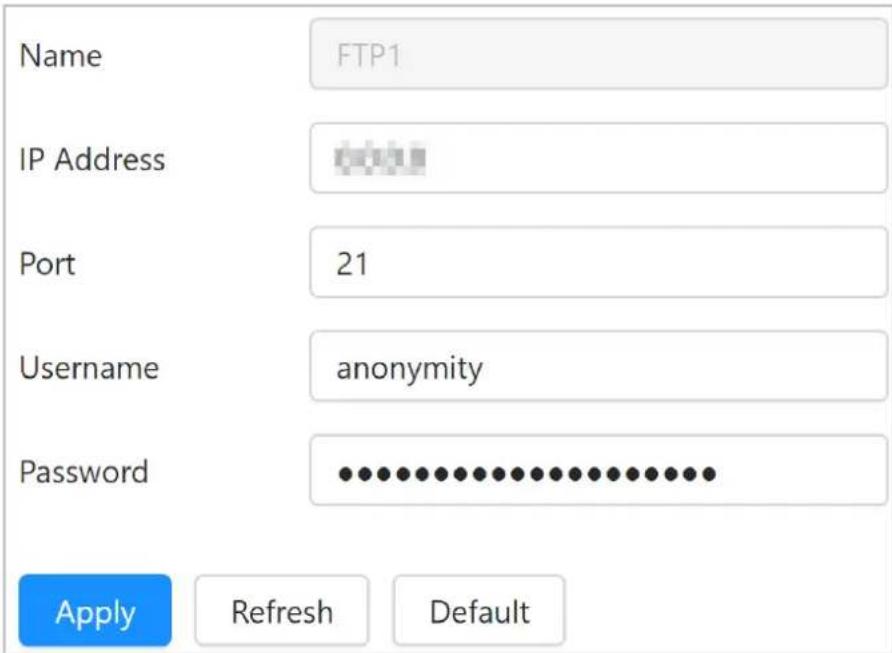
Table 6-13 Descriptions of FTP parameters
| Parameters Description | |
| IP Address | IP address of the PC that is installed with FTP server. |
| Port | The port number of the FTP server. |
| User name | User name and password to access FTP server. |
| Password |
Step 3 Click Apply.
6.3.8 Basic Services
Configure the IP hosts (devices with IP address) that are allowed to visit the device. Only the hosts in the trusted sites list can Log in to the webpagepage. This is to enhance network and data security.
Step 1 Select Network > Basic Services.
Step 2 Click to enable the basic service according to the actual needs.
Figure 6-23 Basic services
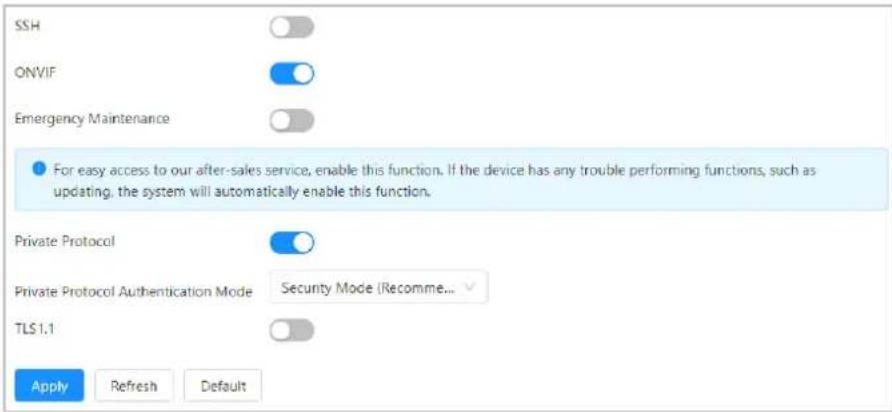
Table 6-14 Descriptions of basic service parameters
| Parameters Description | |
| SSH | You can enable SSH (Secure Shell) authentication to perform safety management. The function is disabled by default. |
| ONVIF | Enabled by default. The device can connect with other network video products through this protocol. |
| Emergency Maintenance | For easy access to our after-sales service, enable the emergency maintenance function. If the device has any trouble performing functions, such as updating, the system will automatically enable this function. If the device has any trouble performing functions, such as updating, the system will automatically enable this function. |
| Private Protocol | Enabled by default. Select the authentication mode from Security Mode and Compatible Mode. Security Mode is recommended. |
| Private Protocol Authentication Mode | |
| TSL1.1 | If enabled, TLS1.1 and TLS1.2 are supported. If disabled, only TLS1.2 is supported. |
Step 3 Click Apply.
6.4 System
This section introduces system configurations, including general, date & time, user management, maintenance and more.
6.4.1 Account
You can manage users, such as add, delete, or edit them. Users include admin, added users and ONVIF users.
Only administrators can manage users and groups.
- Up to 64 users (admin user is not included) can be added, and up to 20 user groups can be added (the group with admin user is not included).
- You can manage users through users or user groups, same user name or group name are not allowed. A user must belong to 1 group at 1 time, and users in a group only have defined
authorities associated with the group.
- Online users cannot modify their own authorities.
- There is one admin by default which has the highest authorities.
6.4.1.1 Adding User
You are admin user by default. You can add users, and configure different permissions.
Procedure
Step 1 Select System > Account > User.
Step 2 Click Add.
Step 3 Configure user parameters.
Figure 6-24 Add users
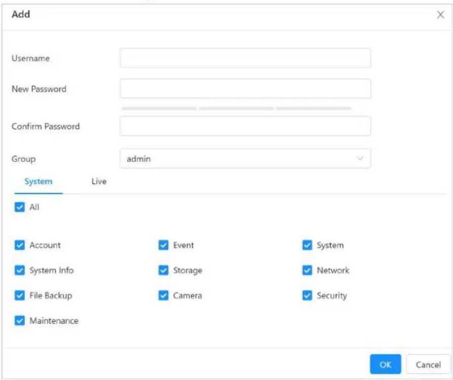
Table 6-15 Descriptions of user parameters
| Parameters Description | |
| Username | User's unique identification. You cannot use an existing user name.The username can contain 31 characters, including numbers, letters, underlines, dashes, dots, and @. |
| New Password Enter | password and confirm it again.The password must consist of 8 to 32 non-blank characters and contain at least two types of characters among upper case, lower case, number, and special character (excluding '' ; : &). |
| Confirm password | |
| Group | The group that users belong to. Each group has different authorities. |
| Parameters Description | |
| MAC | Enter MAC address.When enter the MAC address, only the computer of the MAC address can access the device. |
| System | Select authorities as needed.We recommend giving fewer permissions to normal users than premium users. |
| Live | Select the live view authority for the user to be added. |
Step 4 Click OK.
The newly added users are displayed in the user list.
Related Operations
- Modifying User Information
Click ☑ to edit password, group, memo or authorities.

For admin account, you can only change the password.
- Deleting User
Click to delete the added users.

Admin user cannot be deleted.
6.4.1.2 Adding User Group
You have two groups named admin and user by default, and you can add new group, delete added group or edit group authority and memo.
Procedure
Step 1 Select System > Account > Group.
Step 2 Click Add Group
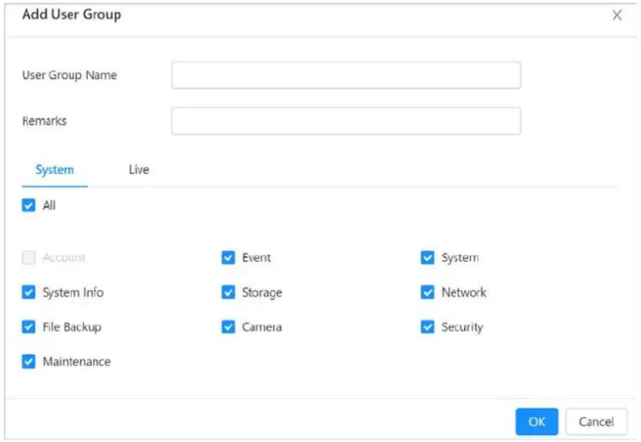
Step 3 Enter the group name and remarks, and then select group authorities.
The username can contain 31 characters, including numbers, letters, underlines, dashes, dots, and @.
Figure 6-25 Add user groups
Step 4 Click OK.
The newly added group is displayed in the group list.
Related Operations
- Modifying User Group Information
Click ✅ to edit password, group, remarks or authorities. - Deleting User Group
Click ☐ to delete the added user groups.

The admin group and user group cannot be deleted.
6.4.1.3 ONVIF User
You can add, delete ONVIF user, and modify their passwords.
Procedure
Step 1 Select System > Account > ONVIF User.
Step 2 Click Add.
Step 3 Configure parameters.
Figure 6-26 Add ONVIF users
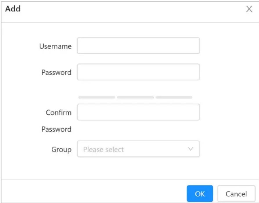
Table 6-16 Descriptions of ONVIF user parameters
| Parameters Description | |
| Username | User's unique identification. You cannot use an existing user name.The username can contain 31 characters, including numbers, letters, underlines, dashes, dots, and @. |
| Password | Enter password and confirm it again.The password must consist of 8 to 32 non-blank characters and contain at least two types of characters among upper case, lower case, number, and special character (excluding '";: &). |
| Confirm password | |
| Group | The group that users belong to. Each group has different authorities. |
Step 4 Click OK.
The newly added user is displayed in the user list.
Related Operations
- Modifying User Information
Click ✅ to edit password, group, remarks or authorities.

For admin account, you can only change the password.
- Deleting User
Click to delete the added users.

The admin account cannot be deleted.
6.4.2 Time
Configure the date and time zone, DST and other parameters of the device.
Step 1 Select System > Time.
Step 2 Configure date and time parameters.
Figure 6-27 Time settings
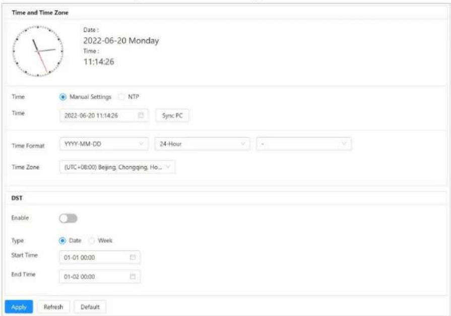
Table 6-17 Descriptions of date and time parameters
| Parameters Description | |
| Time | SelectManual Settingsor NTP.Manually Setting:Configure the parameters manually. ClickSyncPC to sync with the time of computer.NTP:When selecting NTP, the system then syncs time with the internet server in real time.You can also enter the IP address, time zone, port, and interval of a PC which installed NTP server to use NTP.Server:ClickManual Updateto sync time with the internet server in real time.Port:The system supports TCP protocol only and the default setting is 123 (1–65535).Interval:Enter the interval that you want the device to sync time from the NTP server. The maximum value is 65535 minutes. |
| Time Format | Select a date format, includingYYYY-MM-DD, MM-DD-YYYY, andDD-MM-YYYY.Select24-Houror12-Hour. |
| Time Zone | Select according to the location of the device. |
| DST | Some countries or regions implement daylight saving time. Select whether to enable the daylight saving time of the device according to actual needs.Click to enable the DST function.Select Type from Date or Week.Set DST start time and end time. |
Step 3 Click Apply.
6.4.3 Maintenance
6.4.3.1 Auto Maintenance
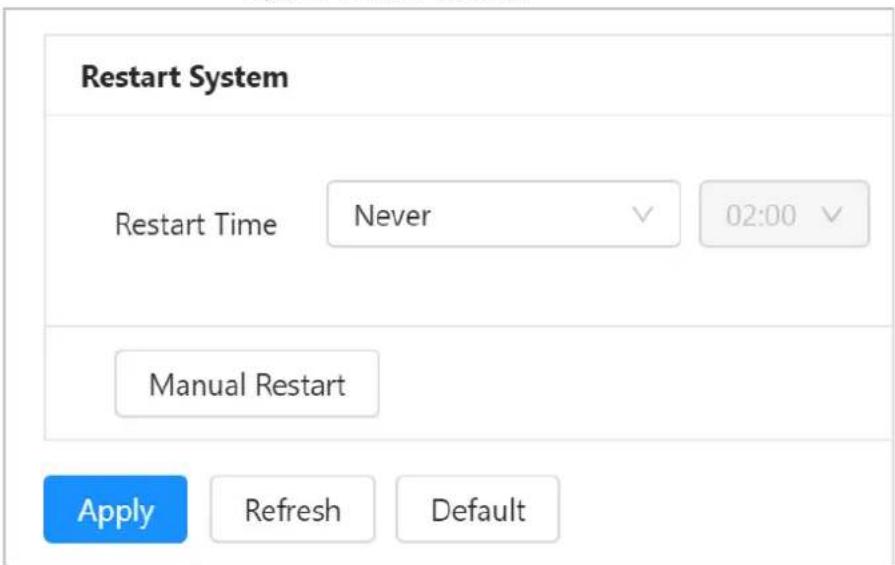
You can restart the system manually, and set the time of auto restart.
Step 1 Select System > Maintenance > Auto Maintain.
Figure 6-28 Auto maintain
Step 2 Restart the device.
- In the Restart System area, set the restart time, and then the system will automatically restart at the defined time every week.
- Click Manual Restart, and then the device restarts immediately.
Step 3 Click Apply.
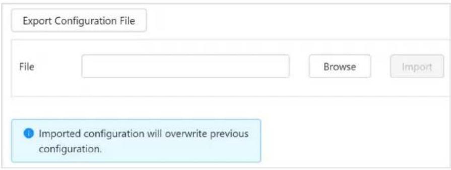
6.4.3.2 Configuring Backup Settings
Import or export system configuration files, and back them up when the configuration files are used by multiple devices.
Step 1 Select System > Maintenance > Config Backup
Step 2 Import or export the file.
- Export configuration information. Click Export Configuration File to export the system configuration file to local storage.
- Import configuration file Click Browse, select local configuration file, and click Import File to import the local system configuration file to the system.
Figure 6-29 Backup
6.4.3.3 Default
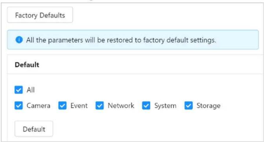
Restore the device to default configuration or factory settings.

The operation will clear the device data. Be cautious.
- Click Factory Defaults, and then all the configurations except IP address and account are reset to default.
- Click Default, and all the configurations are reset to factory settings.
Figure 6-30 Default
6.4.4 Update

- During update, do not disconnect the power supply, network, and do not restart or shut down the device.
- Select correct upgrade files; otherwise some functions might not work properly.
Step 1 Select System > Update.
Step 2 Configure parameters.
Step 3 Click Browse, and then select the upgrade file (.bin file) to be imported.
Step 4 Click Update to update the system.
The device restarts after updating is complete.
6.4.5 Storage
Select System > Storage, and then view information of the local SD card, format SD card, and set storage method for the recorded videos.
For storage methods, you can select SD or FTP.
• SD: Save the recorded videos in the internal SD card.
- FTP: Save the recorded videos in the FTP server.
6.5 System information
6.5.1 Version
Select System Info > Version to view device information such as hardware, system version, and web version.
6.5.2 Legal Information
Select System Info > Legal Info to view software license agreement, privacy policy and open source software notice.
6.6 Logs
6.6.1 Viewing Call History
Select Log > Call History to view the call history, including call types and phone number.
6.6.2 Viewing Logs
The log type includes All, System, User, Config, Event, Operation, and Security.
- System: Includes program start, abnormal close, close, program reboot, device close down, device reboot, system reboot, and system upgrade.
- User: Includes login, logout, adding user, deleting user, editing user, adding group, deleting group, and editing group.
- Config: Includes saving configuration, deleting configuration file, file access, file access error, and file search.
- Event (records events such as video detection, smart plan, alarm and abnormality): includes event start and event end.
• Operation: Includes configuring disk type, clearing data, hot swap, FTP state, and record mode.
• Security: Includes password resetting and IP filter.
Step 1 Select Log > Log.
Step 2 Set the start time and end time, and then select the log types.
Step 3 Click Search.
- Click ☐ or click a certain log, and then you can view the detailed information.
- Click Backup, and then you can back up all searching logs to local PC.

If you want to encrypt the logs, you can select Encrypt Log Backup, enter password, and then click Backup.
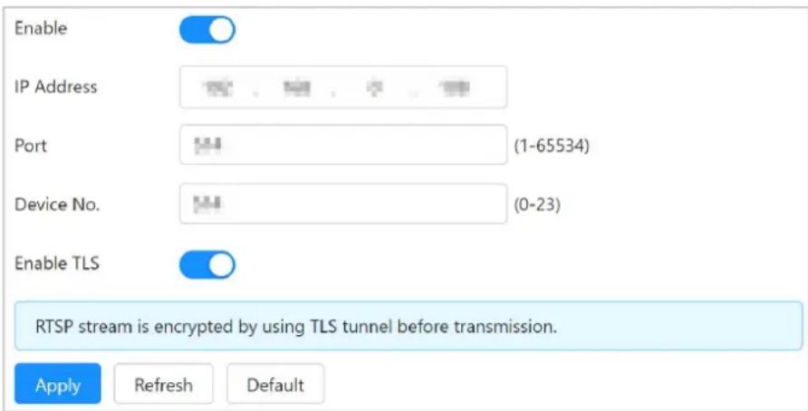
6.6.3 Viewing Remote Logs
Configure remote log, and you can get the related log by accessing the set address.
Step 1 Select Log > Remote Log.
Step 2 Click to enable Remote Log function.
Step 3 Set IP address, port and device No. of the remote server.
Step 4 Click to enable TLS function.
Step 5 Click Apply.
Figure 6-31 Remote Log
6.7 Security
6.7.1 Security Status
Background Information
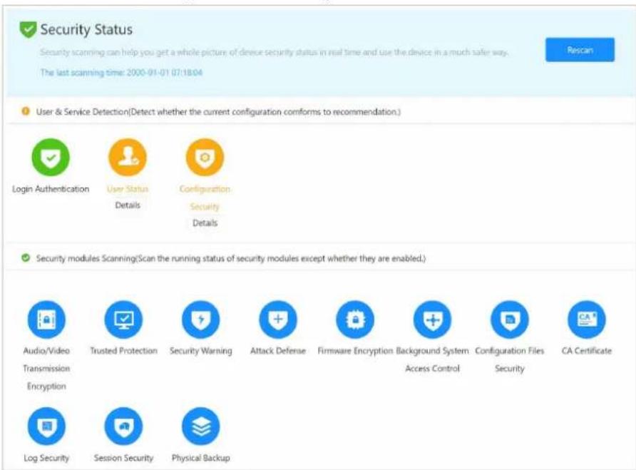
Detect the user and service, and scan the security modules to check the security status of the camera, so that when abnormality appears, you can process it timely.
- User and service detection: Detect login authentication, user status, and configuration security to check whether the current configuration conforms to recommendation.
- Security modules scanning: Scan the running status of security modules, such as audio/video transmission, trusted protection, securing warning and attack defense, not detect whether they
are enabled.
Procedure
Step 1 Select Security > Security Status.
Step 2 Click Rescan to scan the security status of the device.
During scanning, the icon becomes grey. When scanning is complete, the icon becomes blue.
Figure 12-1 Security status
Related Operations
After scanning, different results will be displayed with different colors. Yellow indicates that the security modules are abnormal, and green indicates that the security modules are normal.
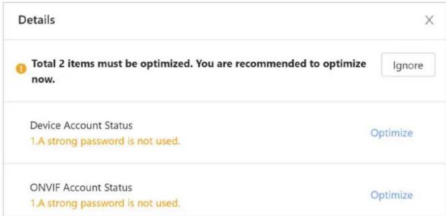
- Click Details to view the details of the scanning result.
- Click Ignore to ignore the exception, and it will not be scanned in next scanning.

Click Joint Detection, and the exception will be scanned in next scanning.
- Click Optimize, and the corresponding page is displayed, and you can edit the configuration to clear the exception
Figure 12-1 View details
6.7.2 System Service
Only when the system service function is enabled can you use the corresponding function.
6.7.2.1 802.1x
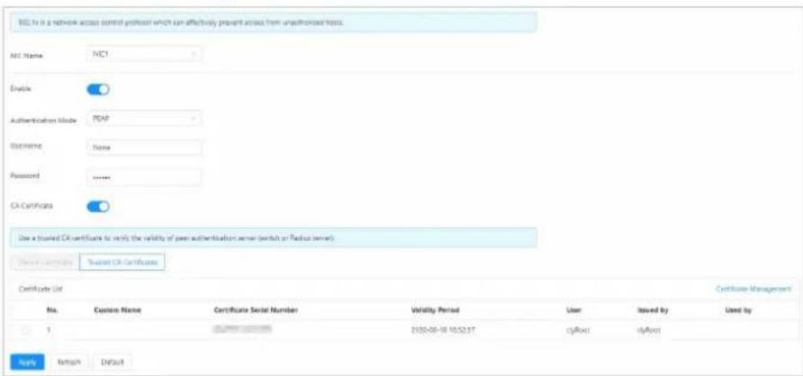
Device can connect to LAN after passing 802.1x authentication. Both switch and device need to pass 802.1x authentication, otherwise you cannot access the device through the network.
Step 1 Select Security > System Service > 802.1x.
Step 2 Select the NIC name as needed, and click to enable it.
Step 3 Select the authentication mode, and then configure parameters.
• PEAP: Protected EAP protocol.
- Select PEAP as the authentication mode.
- Enter the username and password that has been authenticated on the server.
- Click next to CA certificate, and select the trusted CA certificate in list.

If there is no certificate in the list, click Certificate Management at the left navigation bar. For details, see "6.7.4.2 Installing Trusted CA Certificate".
Figure 12-1 802.1x (PEAP)
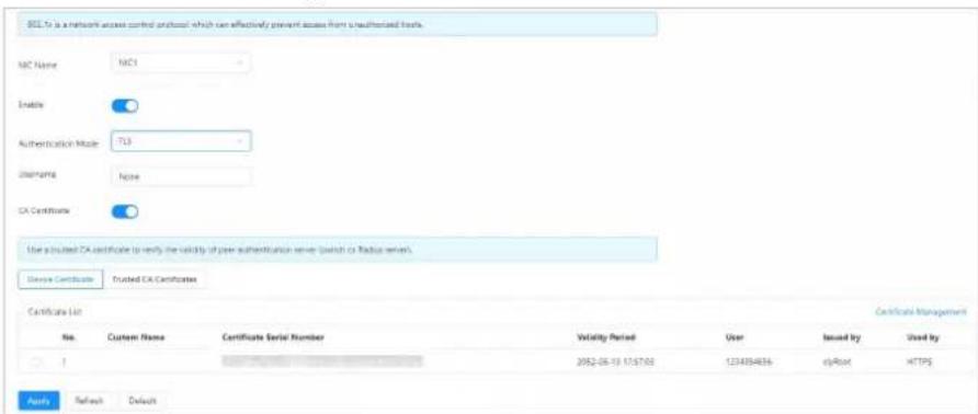
- TLS: TLS: Transport Layer Security. It is applied in two communication application programs to guarantee the security and integrity of the data.
- Select TLS as the authentication mode.
- Enter the username.
- Click next to CA certificate, and select the trusted CA certificate in list.

If there is no certificate in the list, click Certificate Management at the left navigation bar. For details, see "6.7.4.2 Installing Trusted CA Certificate".
Figure 12-1 802.1x (TLS)
Step 4 C lick Apply.
6.7.2.2 HTTPS
Create a certificate or upload an authenticated certificate, and then you can log in through HTTPS with your PC. The HTTPS can protect page authenticity on all types of websites, secure accounts, and keep user communications, identity, and web browsing private.

We recommend you enabling HTTPS service. If this service is disabled, there might be risks of communication data leakage.
Procedure
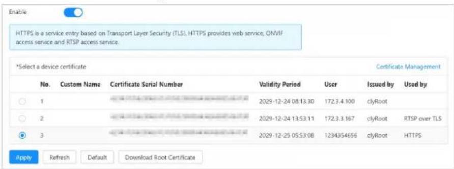
Step 1 Select Security > System Service > HTTPS.
Step 2 Click to enable HTTPS function.

After enabling HTTPS, TLSv1.1 and earlier versions are selected by default. But there is a safety risk to enable the earlier versions of TLSv1.1. Be cautious.
Step 3 Select device certificate.

If there is no certificate in the list, click Certificate Management at the left navigation bar. For details, see "6.7.4.2 Installing Trusted CA Certificate".
Figure 12-1 HTTPS
Step 4 C lick Apply.
Result
Enter http://(IP address) in the browser address bar to log in.
- If the certificate was successfully installed, the login page will be displayed.
- If the certificate has not been installed, the system prompts certificate errors.
6.7.3 Attack Defense
6.7.3.1 Firewall
Configure firewall to limit access to the device.
Step 1 Select Security >Attack Defense >Firewall.
Step 2 Click to enable the firewall function.
Step 3 Select the mode: Allowlist and Blocklist.
Step 4 Click Add.
Figure 12-1 Firewall
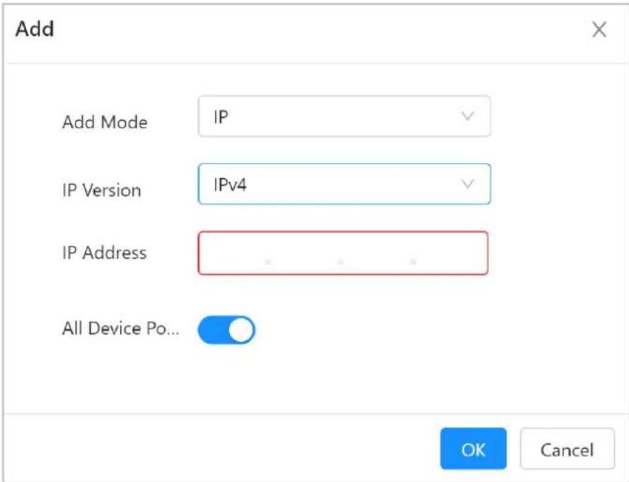
- Allowlist: Only when the IP/MAC of your computer in the allow list, can you access the device. Ports are the same.
- Blocklist: When the IP/MAC of your computer is in the block list, you cannot access the device. Ports are the same.

- IP and MAC of the device cannot be set in the allow list or block list.
- When adding MAC address, you cannot set the port.
- MAC address verification takes effect only when the IP address of the terminal and PC of the user are in the same LAN.
- When the terminal is accessed through WAN, the system can only verify the MAC address of the router.
Step 5 Configure the parameters.
Table 12-1 Descriptions of firewall parameters
| Parameter Description | |
| Add Mode | Select IP Address, IP Segment, MAC Address or All IP Addresses.IP: Select the IP version and enter the IP address of the host.IP Segment: Select the IP version, and then enter the Start Address and End Address of the segment.MAC: Enter the MAC address to be added. |
| IP Address | Set as the IP address of the devices included in the white list or black list. |
| Start Port | Set the access port. Allow terminals in the allow list or block list to access its designated port. |
| End Port |
Step 6 Click OK.
The system goes back to the Firewall page.
Step 7 Click Apply.
6.7.3.2 Account Lockout
Set the allowed times of login attempts and lock time to improve security.
Step 1 Select Security >Attack Defense >Account Lockout
Step 2 Configure the login attempt and lock time for device account.
- Login Attempt: Upper limit of login attempts. If you consecutively enter a wrong password more than the configured value, the account will be locked.
- Lock Time: The period during which you cannot login after the login attempts reaches upper limit.
Figure 12-1 Account lockout
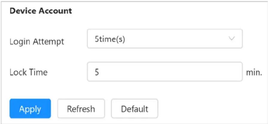
Step 3 Click Apply.
6.7.3.3 Anti-DoS Attack
You can enable SYN Flood Attack Defense and ICMP Flood Attack Defense to defend the device against Dos attack.
Step 1 Select Security >Attack Defense >Anti-DoS Attack.
Step 2 Click next to SYN Flood Attack Defense and ICMP Flood Attack Defense to defend the device against Dos attack.
Figure 12-1 Anti-DoS attack
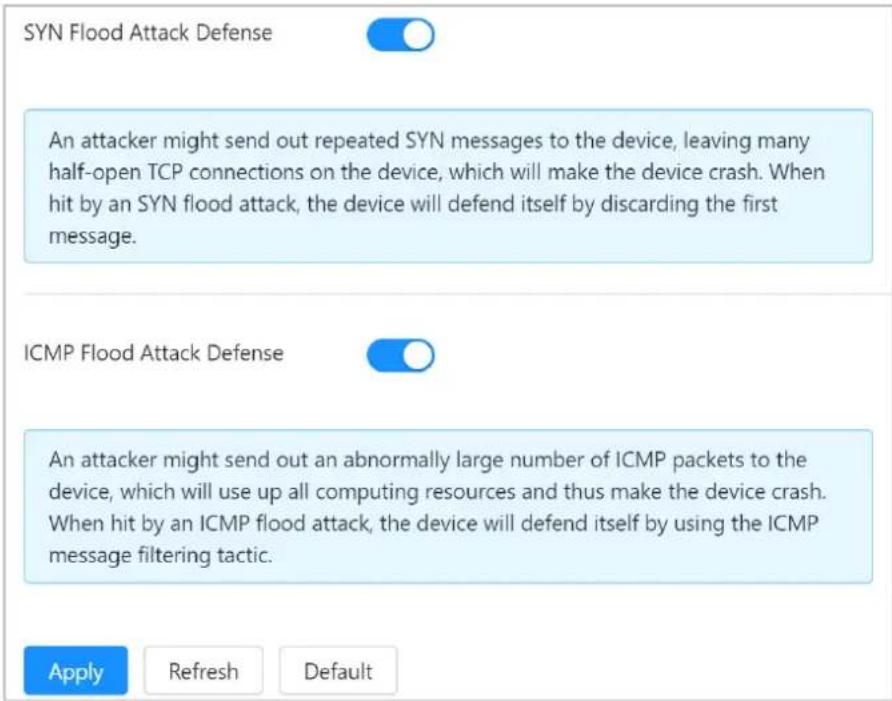
Step 3 Click Apply.
6.7.4 CA Certificate
6.7.4.1 Installing Device Certificate
Create a certificate or upload an authenticated certificate, and then you can log in through HTTPS with your PC.
6.7.4.1.1 Creating Certificate
Create certificate in the device.
Procedure
Step 1 Select Security > CA Certificate > Device Certificate.
Step 2 Click Install Device Certificate.
Step 3 Select Create Certificate, and then click Next.
Step 4 Enter the certificate information.
Figure 12-1 Certificate information (1)
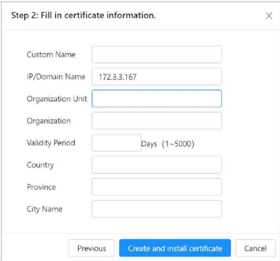
Step 5 Click Create and install certificate.
After the certificate is created successfully, you can view the created certificate on the Device Certificate page.
Related Operations
• Editing the Custom Name of the Certificate
Click Enter Edit Mode, you can edit the custom name of the certificate.
- Downloading Certificate
Click ↓ to download the certificate.
- Deleting Certificate
Click to delete the certificate.
6.7.4.1.2 Applying for and Importing CA Certificate
Import the third-party CA certificate to the device.
Procedure
Step 1 Select Security > CA Certificate > Device Certificate.
Step 2 Click Install Device Certificate.
Step 3 Select Apply for CA Certificate and Import (Recommended), and then click Next.
Step 4 Enter the certificate information.
Figure 12-1 Certificate information (2)
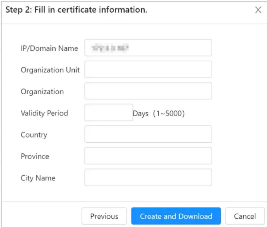
Step 5 Click Create and Download.
Save the request file to your PC.
Step 6 Apply the CA certificate from the third-party certificate authority.
Step 7 Import the signed CA certificate.
1) Save the CA certificate to the PC.
2) Do Step1 to Step3, and click Browse to select the signed CE certificate.
3) Click Install and Import.
After the certificate is created successfully, you can view the created certificate on the Device Certificate page.
- Click Recreate to create the request file again.
- Click Import Later to import the certificate next time.
Related Operations
- Editing the Custom Name of the Certificate
Click Enter Edit Mode, you can edit the custom name of the certificate. - Downloading Certificate
Click ↓ to download the certificate. - Deleting Certificate
Click to delete the certificate.
6.7.4.1.3 Installing Existing Certificate
Import the existing third-party certificate to the camera. When apply for the third-party certificate, you also need to apply for the private key file and private key password.
Procedure
Step 1 Select Security > CA Certificate > Device Certificate.
Step 2 Click Install Device Certificate.
Step 3 Select Install Existing Certificate, and click Next.
Step 4 Click Browse to select the certificate and private key file, and enter the private key password.
Figure 12-1 Certificate and private key
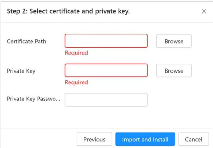
Step 5 Click Import and Install.
After the certificate is created successfully, you can view the created certificate on the Device Certificate page.
Related Operations
- Editing the Custom Name of the Certificate
Click Enter Edit Mode, you can edit the custom name of the certificate. - Downloading Certificate
Click ↓ to download the certificate. - Deleting Certificate
Click to delete the certificate.
6.7.4.2 Installing Trusted CA Certificate
CA certificate is a digital certificate for the legal identity of the device. For example, when the device accesses the LAN through 802.1x, the CA certificate is required.
Procedure
Step 1 Select Security >CA Certificate >Trusted CA Certificates.
Step 2 Select Installing Trusted Certificate.
Step 3 Click Browse to select the certificate.
After the certificate is created successfully, you can view the created certificate on the Trusted CA Certificate page.
Related Operations
• Editing the Custom Name of the Certificate
Click Enter Edit Mode, you can edit the custom name of the certificate.
- Downloading Certificate
Click ↓ to download the certificate.
- Deleting Certificate
Click to delete the certificate.
6.7.5 Video Encryption
The device supports audio and video encryption during data transmission.

We recommend you enable video encryption function. There might be safety risk if this function is disabled.
Step 1 Select Security > Video Encryption.
Step 2 Configure the parameters.
Figure 12-1 Video encryption
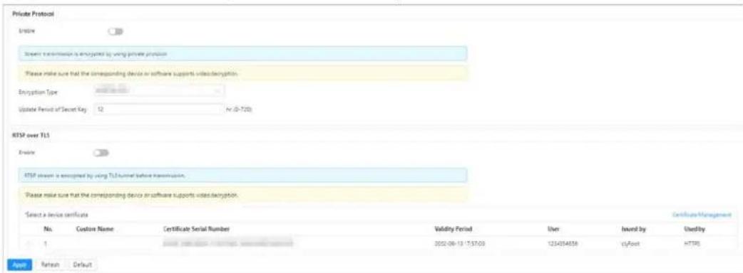
Table 12-1 Descriptions of video encryption parameters
| Area Parameter Description | ||
| Private Protocol | Enable | Enables stream frame encryption by using private protocol.There might be safety risk if this service is disabled. |
| Encryption Type | Use the default setting. | |
| Update Period of Secret Key | Secret key update period.Value range: 0–720 hours. 0 means never update the secret key.Default value: 12. | |
| RTSP over TLS Enable | Enables RTSP stream encryption by using TLS.There might be safety risk if this service is disabled. | |
| Select a device certificate | ||
Step 3 Click Apply.
6.8 Record
View and download the videos within the specified periods.

The device only has one channel.
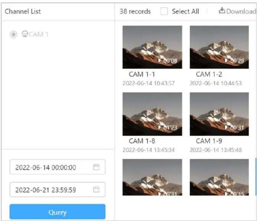
Step 1 Log in to the webpage, click Record.
Step 2 Set the start and end time, and then click Search to view the recording videos. Select one or several recording videos, and then click ↓ to download them.
Figure 6-44 View recording videos
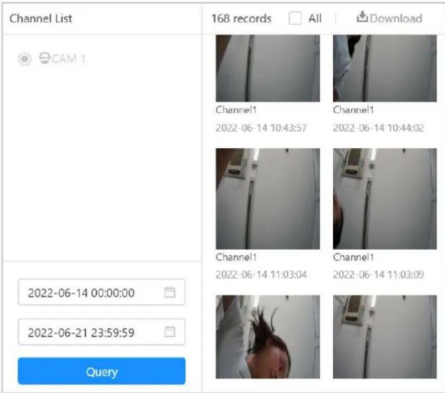
6.9 Picture
View and download the pictures within the specified periods.

The device only has one channel.
Step 1 Log in to the webpage, click Picture.
Step 2 Set the start and end time, and then click Search to view the pictures.
Select one or several pictures, and then click ↓ to download them.
Figure 6-45 View pictures
Appendix 1 Cybersecurity Recommendations
Cybersecurity is more than just a buzzword: it's something that pertains to every device that is connected to the internet. IP video surveillance is not immune to cyber risks, but taking basic steps toward protecting and strengthening networks and networked appliances will make them less susceptible to attacks. Below are some tips and recommendations from Dahua on how to create a more secured security system.
Mandatory actions to be taken for basic device network security:
1. Use Strong Passwords
Please refer to the following suggestions to set passwords:
- The length should not be less than 8 characters.
- Include at least two types of characters; character types include upper and lower case letters, numbers and symbols.
- Do not contain the account name or the account name in reverse order.
- Do not use continuous characters, such as 123, abc, etc.
- Do not use overlapped characters, such as 111, aaa, etc.
2. Update Firmware and Client Software in Time
- According to the standard procedure in Tech-industry, we recommend to keep your device (such as NVR, DVR, IP camera, etc.) firmware up-to-date to ensure the system is equipped with the latest security patches and fixes. When the device is connected to the public network, it is recommended to enable the "auto-check for updates" function to obtain timely information of firmware updates released by the manufacturer.
- We suggest that you download and use the latest version of client software.
"Nice to have" recommendations to improve your device network security:
1. Physical Protection
We suggest that you perform physical protection to device, especially storage devices. For example, place the device in a special computer room and cabinet, and implement well-done access control permission and key management to prevent unauthorized personnel from carrying out physical contacts such as damaging hardware, unauthorized connection of removable device (such as USB flash disk, serial port), etc.
2. Change Passwords Regularly
We suggest that you change passwords regularly to reduce the risk of being guessed or cracked.
3. Set and Update Passwords Reset Information Timely
The device supports password reset function. Please set up related information for password reset in time, including the end user's mailbox and password protection questions. If the information changes, please modify it in time. When setting password protection questions, it is suggested not to use those that can be easily guessed.
4. Enable Account Lock
The account lock feature is enabled by default, and we recommend you to keep it on to guarantee the account security. If an attacker attempts to log in with the wrong password several times, the corresponding account and the source IP address will be locked.
5. Change Default HTTP and Other Service Ports
We suggest you to change default HTTP and other service ports into any set of numbers between
1024–65535, reducing the risk of outsiders being able to guess which ports you are using.
6. Enable HTTPS
We suggest you to enable HTTPS, so that you visit Web service through a secure communication channel.
7. MAC Address Binding
We recommend you to bind the IP and MAC address of the gateway to the device, thus reducing the risk of ARP spoofing.
8. Assign Accounts and Privileges Reasonably
According to business and management requirements, reasonably add users and assign a minimum set of permissions to them.
9. Disable Unnecessary Services and Choose Secure Modes
If not needed, it is recommended to turn off some services such as SNMP, SMTP, UPnP, etc., to reduce risks.
If necessary, it is highly recommended that you use safe modes, including but not limited to the following services:
- SNMP: Choose SNMP v3, and set up strong encryption passwords and authentication passwords.
- SMTP: Choose TLS to access mailbox server.
- FTP: Choose SFTP, and set up strong passwords.
- AP hotspot: Choose WPA2-PSK encryption mode, and set up strong passwords.
10. Audio and Video Encrypted Transmission
If your audio and video data contents are very important or sensitive, we recommend that you use encrypted transmission function, to reduce the risk of audio and video data being stolen during transmission.
Reminder: encrypted transmission will cause some loss in transmission efficiency.
11. Secure Auditing
- Check online users: we suggest that you check online users regularly to see if the device is logged in without authorization.
- Check device log: By viewing the logs, you can know the IP addresses that were used to log in to your devices and their key operations.
12. Network Log
Due to the limited storage capacity of the device, the stored log is limited. If you need to save the log for a long time, it is recommended that you enable the network log function to ensure that the critical logs are synchronized to the network log server for tracing.
13. Construct a Safe Network Environment
In order to better ensure the safety of device and reduce potential cyber risks, we recommend:
- Disable the port mapping function of the router to avoid direct access to the intranet devices from external network.
- The network should be partitioned and isolated according to the actual network needs. If there are no communication requirements between two sub networks, it is suggested to use VLAN, network GAP and other technologies to partition the network, so as to achieve the network isolation effect.
- Establish the 802.1x access authentication system to reduce the risk of unauthorized access to private networks.
- Enable IP/MAC address filtering function to limit the range of hosts allowed to access the
device.
More information
Please visit Dahua official website security emergency response center for security announcements and the latest security recommendations.
ENABLING A SAFER SOCIETY AND SMARTER LIVING
- Emergency Phone Terminal
- User's Manual
- Foreword
- General
- Models
- Revision History
- Privacy Protection Notice
- About the Manual
- Important Safeguards and Warnings
- Transportation Requirements
- Storage Requirements
- Operation Requirements
- Installation Requirements
- WARNING
- Maintenance Requirements
- Table of Contents
- Foreword ....
- Important Safeguards and Warnings....III
- Overview....1
- Unpack and Check....2
- Structure .... 3
- Networking....8
- Installation and Wiring....9
- Wiring 13
- Web Operations....19
- Starting the Device....19
- General....21
- Video....24
- Overview
- Introduction
- Functions
- Unpack and Check
- Structure
- Mainboard Ports
- Front Panel
- Rear Panel
- Networking
- Installation and Wiring
- Dimensions
- Installation
- Building the Foundation
- Pole Mount
- Wiring
- External AC Power Port Connection
- Network Connection
- Dot-matrix Display Connection
- Local Alarm Input Cable Connection
- Local Alarm Output Cable Connection
- Web Operations
- Starting the Device
- Initializing the Device
- Background Information
- Procedure
- Logging in to Webpage
- Prerequisite
- Resetting Password
- Prerequisites
- General
- Call Linkage
- PSTN
- Zone
- Zone Configuration
- Protection Zone Management
- Video
- Encode
- Image
- Overlay
- Configuring Channel Title
- Configuring Time Title
- Configuring Image Information
- Audio
- Advertising
- Configuring Advertising Resources
- Configuring Advertising Texts
- Lock
- Network
- TCP/IP
- Port
- 2G/4G
- UPnP
- Register
- SIP Server
- FTP
- Basic Services
- System
- Account
- Adding User
- Related Operations
- Adding User Group
- ONVIF User
- Time
- Maintenance
- Auto Maintenance
- Configuring Backup Settings
- Default
- Update
- Storage
- System information
- Version
- Legal Information
- Logs
- Viewing Call History
- Viewing Logs
- Viewing Remote Logs
- Security
- Security Status
- System Service
- 802.1x
- HTTPS
- Result
- Attack Defense
- Firewall
- Account Lockout
- Anti-DoS Attack
- CA Certificate
- Installing Device Certificate
- Creating Certificate
- Applying for and Importing CA Certificate
- Step 5 Click Create and Download.
- Installing Existing Certificate
- Installing Trusted CA Certificate
- Video Encryption
- Record
- Picture
- Appendix 1 Cybersecurity Recommendations
- Mandatory actions to be taken for basic device network security:
- Use Strong Passwords
- Update Firmware and Client Software in Time
- "Nice to have" recommendations to improve your device network security:
- Physical Protection
- Change Passwords Regularly
- Set and Update Passwords Reset Information Timely
- Enable Account Lock
- Change Default HTTP and Other Service Ports
- Enable HTTPS
- MAC Address Binding
- Assign Accounts and Privileges Reasonably
- Disable Unnecessary Services and Choose Secure Modes
- Audio and Video Encrypted Transmission
- Secure Auditing
- Network Log
- Construct a Safe Network Environment
- More information
Brand : Dahua Technology
Model : VTA8311AB
Category : Sound alarm