Pressure Storm 2500 - Pressure washer Lifan - Free user manual and instructions
Find the device manual for free Pressure Storm 2500 Lifan in PDF.

User questions about Pressure Storm 2500 Lifan
0 question about this device. Answer the ones you know or ask your own.
Ask a new question about this device
Download the instructions for your Pressure washer in PDF format for free! Find your manual Pressure Storm 2500 - Lifan and take your electronic device back in hand. On this page are published all the documents necessary for the use of your device. Pressure Storm 2500 by Lifan.
USER MANUAL Pressure Storm 2500 Lifan
natural_image
Green LIFAN water purifier with attached hose and control panel, displayed against blurred bokeh background (no text or symbols visible)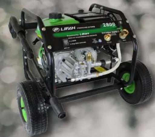
natural_image
Close-up of a green and black LIFAN water heater with visible components and branding (no readable text or symbols beyond branding)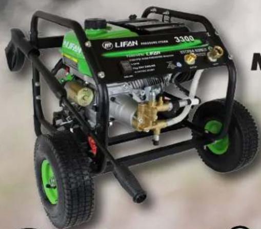
natural_image
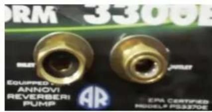
Exterior view of a green and black LIFAN 3300 pressure water heater with visible hoses and branding (no text-heavy elements)
natural_image
Stylized 3D logo design featuring a stylized 'L' within a circular frame, set against a green background (no text or symbols)Models LFQ2130 (-CA)
LFQ2565 (-CA)
LFQ2565E (-CA)
LFQ2865 (-CA)
LFQ3370 (-CA)
LFQ3370E (-CA)


Equipped with ANNOVI REVERBERI Pumps
Operating Instructions & Owners' Manual
Please read this manual carefully before operating your new pressure washer. (CA) in the model number designated Californai Compliant by CARB 3/3/2016
Operating Instructions
And
Owner's Manual
PRESSURE STORM SERIES
LFQ2130(CA)
LFQ2565(CA), LFQ2565E(CA)
LFQ2865 (CA)
LFQ3370 (CA), LFQ3370E (CA)
Record Purchase Here
Model # ____
Engine ID # ____
(Unique Identifier stamped on engine crankcase)
Date of Purchase ____
Purchase Location ____
PLEASE KEEP AND READ THIS MANUAL CAREFULLY BEFORE OPERATING YOUR NEW LIFAN Power USA Pressure Washer
(-CA) Indicates this unit is CARB Certified
(E) Indicates this unit is Electric Start
ATTENTION: Rental Companies and Private Owners who loan this equipment to others!!!!
All persons to whom you rent/loan this pressure washer to must have access to and read this manual. Keep this owner's manual with the pressure washer at all times and advise all persons who will operate the machine to read it. You must also provide personal instruction on how to safely set-up and operate the pressure washer and remain available to answer any questions a renter/borrower might have.
Only Trained Adults should set up and operate the Pressure Washer. DO NOT LET CHILDREN OPERATE THIS EQUIPMENT!!!!
Always wear safety apparel when operating this equipment, safety glasses, ear protection, insulated waterproof gloves, and non-slip protective shoes are recommended. When using any cleaning chemicals refer to the chemical label for safety instructions concerning those chemicals for use of a respiration mask.
Never operate or let anyone operate this equipment while under the influence of any alcohol, drugs, or medication or when fatigued.
Owner's Manuals are available from Lifan Power USA at 1-866-471-7464.
Pressure Washer
Deinition of Pressure Washer: A machine that cleans dirty surfaces with high pressure water. This pressure washer produces cold water high pressure spray. Cleaning chemicals may be incorporated into the spray if desired on models equipped for "chemical induction through the pump". The LFQ2565 and LFQ2565E are clear water only. The pressure pump for this equipment is powered by a gasoline internal combustion engine.
WARNING: SPECIAL HAZARDS
- CO Poisoning: Exhaust from engine contains carbon monoxide, a poisonous gas that can cause carbon monoxide poisoning and possible death if inhaled.
- Injecon Injury: High-pressure spray can pierce skin and underlying issues, leading to serious injury and possible amputon. Such aninjecon injury can result in blood poisoning and/or severe issue damage.
- Flying Debris: High-pressure spray can cause ying debris and possible surface damage.
• Electric shock: Operang equipment in wet conditions or near water can cause electric shock.
• Chemical Exposure: Cleaning chemical vapors or contact with skin may be hazardous. - Fire/Explosion: Engine sparking can ignite fuel or other ammable liquids or vapors in the vicinity. Hot exhaust from engine can ignite combustible materials.
• Burns: Pressure Washer pump and engine are hot surface that can cause burn injuries. Detailed
Equipment Protection Facts
Inspect Upon Delivery: FIRST! Inspect form missing or damaged components. See "Initial Set-Up/Installation" section for where to report missing or damaged parts.
Add Engine Oil: Engine is shipped without oil. See the "Engine Manual" section of this manual for instructions on capacity and viscosity recommendations.
Water Flow Requirements: Make sure your supply water low rate is 20% higher than the pressure washer's low rate (see "Operations", section for detail), and that your water is clean and particle free.
Do not run Pressure Washer without proper inlet water supply to high pressure pump and for more than 1 minute without depressing trigger on gun to circulate water to avoid damaging pump.
Chemical Spraying: Use only approved pressure washer chemicals designed for high-pressure use. Use so adjustment knob to regulate cleaning power (on select units).
Storage: Do not allow water to freeze in the pump, hose, or spraygun(s). See "Storage" for more information.
Maintenance Schedule: Engine and pump require periodic inspection and servicing to keep pressure washer functioning efficiently. See "Maintenance Schedule Summary" for frequency of servicing.
Battery: A battery is required for electric start feature (Denoted by in model # only). A battery is not included. Purchase a standard 12VDC, 10Ah battery, and further detail in "Specifications" section.
PLEASE READ THE
FOLLOWING INSTRUCTIONS!
-
Unit Shipped without engine oil. Axial Cam Pump shipped with correct oil and sealed. See Pre-operang Instrucons for further informaon.
-
For repair under Warranty or quesons concerning Warranty, DO NOT RETURN this product to the Store where purchased. Follow the procedures as outlined in the "WARRANTY POLICY" and "WARRANTY REGISTRATION" in the Owner's Manual. For any quesons visit www.lifanpowerusa.com or call 1-866-471-7464, Opon 2 Warranty and Service.
-
Read the "Owner's Manual" prior to operating any equipment and familiarize yourself with the proper and safe operation of the equipment. If you have any questions, visit www.lifanpowerusa.com or call 1-866-471-7464 Opon 2 Warranty and Service.
4.
This Owner's Manual is for the Following Models:
| LFQ2130(CA) | LFQ2565 (CA) | LFQ2865 (CA) | LFQ3370 (CA) |
| LFQ2565E (CA) | LFQ3370E (CA) | ||
(E) Indicates unit is Electric Start Feature (Battery not included.
(CA) Indicates this unit is CARB Certified for California

TABLE OF CONTENTS
Preface 5
Product Specifications 6
Safety Instructions 7
Controls and Features 10
PRE-OPERATING INSTRUCTIONS
Assembly 13
Engine Oil Level Check 18
Engine Fuel Level Check 19
Air Cleaner Element Check 20
Connecting Inlet/Outlet/Chemical Injection Hose 21
Connecting Nozzle 22
Battery Specifications 24
Operation of Pressure Washer 25
Transporting and Storing the Unit 29
Maintenance 30
Troubleshooting 35
Water Pump Safety 36
Safe Operations 37
Limited Warranty Policy 40
Diagrams 44

Preface
Thank you for choosing LIFAN Power USA for your Power Equipment needs. LIFAN Power USA prides itself on providing quality products at affordable pricing, creating the “Best Equipment Value on Today’s Market!”
Your High Pressure Washer utilizes our Industrial Grade Gasoline Engines combined with the premium grade. Annovi Reverberi High Pressure Pump to produce a high pressure water spray for cleaning purposes. Do not use this unit for other purposes as unforeseen hazards or equipment damage may result. This unit is intended for OUTDOOR USE ONLY.
All LIFAN Power USA products are manufactured utilizing the latest technology. Built with quality components, your new Power Equipment Product will give you years of dependable service. Your unit, along with all of LIFAN Power USA products are designed, engineered, and manufactured with LIFAN's Industrial Grade Gasoline Engine.
This Owner's Manual will provide you with all of your needed information for your new Power Equipment Product, including Safe Operation and Maintenance of your unit. Please keep and read this Owner's Manual completely and carefully prior to operation. Keep this Owner's Manual for assistance in the future, such as proper maintenance schedules and tips to prolong the life and effective use of your unit. If you require assistance, please visit our website (www.lifanpowerusa.com) or call toll free 866-471-7464 Option 2 Warranty and Service.
This Owner's Manual contains information with respect to the newest products at the time of publication. Due to revision and modifications, the information noted in the Owner's Manual might vary from the actual status. This Owner's Manual is subject to change without notice. The copyright of the Owner's Manual belongs to EquipSource, LLC. Any group or individual is forbidden to reprint or copy any of this Owner's Manual without the written consent of EquipSource, LLC.
FOR ALL WARRANTY AND SERVICE RELATED ISSUES/QUESTIONS DONOT RETURN YOUR UNIT TO THE STORE OR DEALER WHERE THE ITEM WAS PURCHASED. FOR SERVICE VISIT LIFAN POWER USA'S WEBSITE (WWW.LIFANPOWERUSA.COM) OR CALL 1-866-471-7464 Option 2 Warranty and Service. WE WILL BE HAPPY TO HANDLE YOUR WARRANTY YISSUE OR DIRECT YOU TO THE NEAREST "AUTH ORIZE D SERVICE CENTER."


PRODUCT SPECIFICATIONS
PRESSURE STORM PRESSURE WASHERS
| Model Size | LFQ2130(CA) | LFQ2565(E)(CA) | LFQ2865(CA) | LFQ3370(E)(CA) |
| Pump Manufacturer | Annovi Reverberi | Annovi Reverberi | Annovi | Annovi Reverberi |
| Pump Type | RPV Axial Cam | RPV Axial Cam | RMV | RQV Axial Cam |
| Pressure Output (psi ^1 ) | 2100 psi | 2500 psi | 2800psi | 3300 psi |
| Delivery Output (gpm ^2 ) | 2 gpm | 2 gpm | 2.5 | 3 gpm |
ENGINE
| Manufacturer | LIFAN | LIFAN | LIFAN | LIFAN |
| Model | LF152F-3Q | LF168-2FBQ | LF168F-2BQ | LF170F-BQ |
| Maximum Horsepower (MHP) | 3mph | 6.5mph | 6.5mph | 7mph |
| Engine Displacement | 97.7cc | 196cc | 196cc | 212cc |
| Starting System | Recoil | Recoil/Electric (E) | Recoil | Recoil/Electric (E) |
| Fuel Tank Capacity | .37 Gallon | 0.66 Gallons | 0.95 Gallons | 0.95 Gallons |
| Engine Type | 4 Stroke OHV | 4 Stroke OHV | 4 Stroke OHV | 4 Stroke OHV |
| Fuel Type | 87 Octane Gasoline | 87 Octane Gasoline | 87 Octane Gasoline | 87 Octane |
| Fuel Compliance | 10% Ethanol or Less | 10% Ethanol or Less | 10% Ethanol or Less | 10% Ethanol or Less |
| Oil Type & Amount | SAE10w30w 20oz | SAE10w30w 20oz | SAE10w30w 20oz | SAE10w30w 20oz |
| Low Oil Shuto Protecon | Yes | Yes | Yes | Yes |
| CARB Cered | (CA) Models Only | (CA) Models Only | (CA) Models Only |
DIMENSIONS
| Length(inch) |
| Width(inch) |
| Height (inch) |
| Weight (lbs) |
ACCESSORIES
| Adjustable Spray Lance | 1 ea. | 1 ea. | 1 ea. |
| Gun | 1 ea. | 1 ea. | 1 ea. |
| Inlet Hose | 1 ea. | 1 ea. | 1 ea. |
| Outlet Hose | 1 ea. | 1 ea. | 1 ea. |
| Chemical Injector | N/A | 1 ea. | 1 ea. |
| Adjustable spray Nozzle | |||
| Wand & Hose Bracket | 1 ea. | 1 ea. | 1 ea. |
| Mobility/Wheel Kit | 2 Wheels | 2 Wheels/T-bar | 2 Wheels/T-bar handles |
Comments
PSI ^1 = Pounds per Square Inch
GPM ^2 = Gallons per Minute


Safety Instrucons

This is the safety alert symbol. It is used to alert you to potential personal injury hazards. Obey all safety messages that follow this symbol to avoid possible injury or death.
For your safety read this manual carefully. Become familiar with the proper operation, care, and maintenance of your LIFAN PressureStorm Pressure Washer.
The safety and alert symbol ( ⚠️ ) is used with a signal word ( CAUTION, DANGER, WARNING ), a pictorial and/or safety message to alert you to hazards. CAUTION indicates a hazard that, if not avoided, could result in minor or moderate injury. DANGER indicates a hazard that, if not avoided, could result in death or serious injury. WARNING indicates a hazard that, if not avoided, could result in death or serious injury.
Hazard Symbols and Meanings


WARNING!
Running pressure washer emits carbon monoxide: an odorless, colorless, poison gas. Breathing carbon monoxide can cause nausea or death!
ONLY operate pressure washers outdoors.
Exhaust gas must be prevented from entering conined areas.
Direct exhaust gas away from windows, doors, ventilation and other openings.
Do not operate pressure washer inside or under any buildings.

WARNING!
The Engine exhaust from this pressure washer contains chemicals known to the State of California to cause birth defects, reproductive harm and cancer.

Safety Instrucons
| WARNING! | |
 | Rapid recoil of starter cord (kickback) may pull hand and arm forw toward engine at a rapid rate.Broken bones, bruises, sprains, and fractures may result. 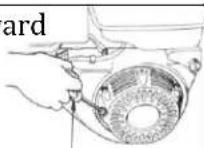 |
| When starting engine, pull cord slowly until tension is felt, then pull rapidly to avoid kickback. | |
WARNING!
| Fuel and its vapors are extremely lammable and explosive. | |
| Fire or explosion can cause severe burns or death. |
WHEN ADDING OR DRAINING FUEL
- Turn pressure washer off and let it cool for at least three minutes before removing fuel cap. Loosen cap slowly in order to relieve pressure in the fuel tank.
• Fill or drain fuel tank outdoors. Do not excessively inhale fuel vapors. - Keep away from open lames or sparks and other sources of ignition.
• Do NOT smoke while illing fuel tank. - Do NOT overill tank. Allow space for fuel expansion.
WHEN TRANSPORTING OR REPAIRING EQUIPMENT
• Transport pressure washer with the fuel valve in the off position.
• Repair pressure washer with the fuel tank empty or the fuel valve in the off position.
- Disconnect spark plug wire before transport or service.
WHEN STORING FUEL OR EQUIPMENT CONTAINING FUEL
- Store away from furnaces, stoves, water heaters, clothes dryers or other appliances that have pilot light or other ignition source because they can ignite fuel vapors.
WHEN STARTING EQUIPMENT
- Ensure spark plug, mufler, air cleaner, and fuel cap are in place.
• Do NOT crank engine with spark plug removed.
• If fuels spills, wait until it evaporates before starting engine.
WHEN OPERATING EQUIPMENT
• Do NOT choke carburetor to stop engine.
- Do NOT tip engine or equipment at an angle, which causes fuel to spill.
Safety Instrucons

WARNING!
While engine is running temperature may exceed 150^ F ( 65^ C). Server burns may occur.
Exhaust heat/gasses can ignite combustibles, structures or damage fuel tank causing a ire.
• Do NOT touch hot surfaces and do avoid exhaust gases.
- Allow pressure washer to cool before touching.
- Keep at least 7 ft. (183cm) clearance on all sides of pressure washer including overhead clear.
• Relective exhaust heat may damage fuel tank causing ire.
- Code of Federal Regulation(CFR) Title 36 Parks, Forests, and Public Property require equipment powered by an internal combustion engine to have a spark arrester, maintained in working order, complying to USDA Forestservice standard 5100 -1c or later revision. In the state of California a spark arrester is required under section 4442 of the California Public resources code.
WARNING!
Unintentional sparking can result in ire or electrical shock.

WHEN TESTING FOR ENGINE SPARK
• Do NOT check for spark with the spark plug removed.
• Use approved spark plug tester.
WHEN REPAIRING OR ADJUSTING WATER PUMP
- Disconnect the spark plug wire from the spark plug and place the wire where it cannot contact spark plug.
CAUTION!
Improper use and care of this pressure washer will cause damage and shorten its lifespan. Failure to follow these actions will void all warranties.
• Use pressure washer only for appropriate and designated purposes.
• The dealer or customer helpline (1-866-471-7464) can instruct you on intended uses.
• Pressure washer must be placed on a level surface.
• Do NOT expose pressure washer to extreme conditions. Excessive dust, moisture, and corrosive vapors will damage unit.
• Cooling slots must be kept clear of debris.
- Shut off pressure washer and take to a qualified service center if the pressure washer fails to operate properly.
NOTE: NEVER ALLOW PRESSURIZED WATER EXITING SPRAY GUN TO CONTACT SKIN OF HUMAN OR ANIMAL.

Controls and Features
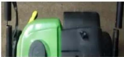
Electric Start Models Choke on Panel inlet/Outlet Connections on Panel
Panel for LFQ2865 - LFQ3370 - LFQ3370E
Legend
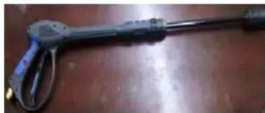
- Spray Gun – Lance and Gun screw together to form Spray Gun
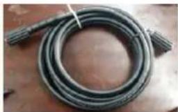
- Outlet Hose --- supplies pressurized water from pump to spray gun.
- Water Pump - Annovi Reverberi AR Direct Drive High Pressurized Water Pump.
- Frame - One Inch steel tubing for maximum protection.
- Legs - Support for Pressure Washer.
- Mobility Kit/Wheels - Pneumatic Tires and Wheels for easy mobility.
- Fuel Cap - Check/add fuel


Control Panel Features
Your LFQ2865, LFQ3370, and LFQ3370E are designed for convenient connections for the inlet and outlet hose connections on the panel and pre-plumbed from the back of the panel to the pump. With the on/off switch (Electric Start Switch on E models) and the Pull to Choke and Push to run panel mounted choke you have everything at your ingertips.
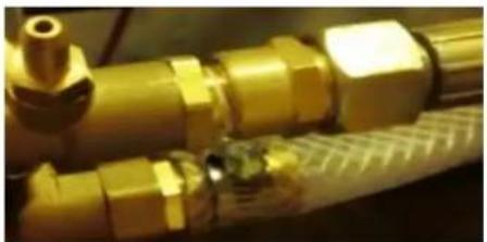
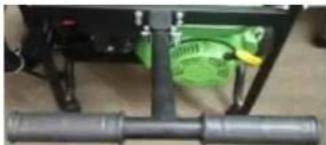
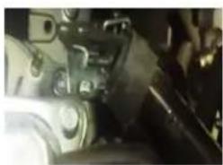
natural_image
Close-up of a yellow industrial pipe fitting with fittings and a valve (no visible text or symbols)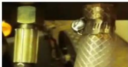
natural_image
Close-up of a metallic mechanical component with a cylindrical shaft and textured surface, possibly a valve or sensor device (no visible text or symbols)Key-on/off Switch Pull to Choke/Push to Run Inlet/Quick Connect Outlet Pre-Plumbed from High Pressure Pump to inlet/Outlet on Panel
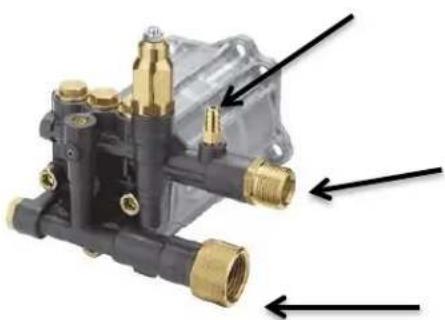
Always check the inlet and outlet connections on the pump and back of panel for leaks or wear.

Pre-Operang Instrucons: Assembly
Your LIFAN Power USA pressure washer is packaged without fuel and engine oil. Some assembly is required before operating your LIFAN Power USA Generator.
For further assistance in assembling your generator please visit our website (www.lifanpowerusa.com) or call 1-866-471-7464 during ofic ehours.
BOX CONTENT:
- Pressure Washer
- Accessory Kit
o 1 ea. ---Spark Plug Removal Tool o 1 ea. - Outlet
Hose
o 1 ea. - Lance w/adjustable spray nozzle (Combines with Gun to form
Spray Gun) o 1 ea. - Gun (Combines with Lance to form Spray Gun) o 1 ea.
- Spray Gun & Hose Bracket
- 1 ea. – Chemical Injector Hose except LFQ2565 and LFQ2565E
- Owner's Manual
• Warranty Registration Card - Warranty Policy
- Wheel Kit
2 ea. - Pneumatic Wide Tires and Wheels/LFQ2565(E) Low Proile solid 12"
2 ea. - Rubber Support Leg
1 ea. - Axle
1 ea.- T-Bar Handle LFQ2865, LF3370 (E)
Hardware Bag
6 ea. - 12mm Bolt
2 ea. - Handle Bolt (50mm Long)
2ea.-3-Point Wing Nut
2 ea. - 14mm Nut
2 ea. - 18mm Nut
2 ea. - Cotter Pin
2 ea. - 1in Washer

Pre-Operang Instrucons: Assembly
UNPACKING THE GENERATOR:
- Set the carton on a lat, rigid surface.
- Remove all loose contents from carton EXCEPT the Engine/Pump/Bottom Frame portion of pressure washer and set them beside carton.
- Open box completely by cutting each corner from top to bottom.
- Leave Pressure Washer on the remainder of the box until Wheel Kit is installed. Never attempt to put oil in engine or operate the equipment until fully assembled.
- Locate all box contents and place them beside the pressure washer. (Some Items may be packaged within the voids of the pressure washer itself.)
INSTALLATION:
The Following Tools are needed to assemble the Pressure Washer:
- Safety Glasses
• 8mm-14mm Wrench Set
• 8mm-14mm Ratchet & Socket Set
• 18mm Ratchet & Socket
HANDLE INSTALLATION: LFQ2565
Slide both ends of Handle into the two poles located behind the engine. The Handle should bend away from the water pump/engine.
natural_image
Close-up of a green and black industrial machine component (no visible text or symbols)Insert Handle Bolt through the holes of the handle and pole. Fasten with 3-point wing nut. The Wing Nut should be on the outside of the handle. The head of the Handle Bolt should it flush against inside of handle.

natural_image
Close-up of a metallic mechanical component with a hole and a flat pin on a red surface (no text or symbols visible)

Pre-Operang Instrucons: Assembly
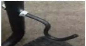
For electric Start models attach starter wire hanger to handle bolt per picture.
natural_image
Close-up of a mechanical device with green and black components, no visible text or symbols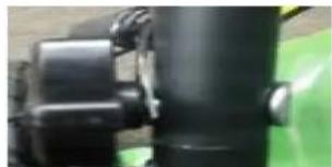
natural_image
Close-up of a black mechanical component with green base, no visible text or symbolsHandle Installation LFQ2865, LFQ3370 (E)
- These units come with a T-Bar handle. The mount bracket to the frame is pre-drilled and threaded for the 4 bolts to each the handle.
natural_image
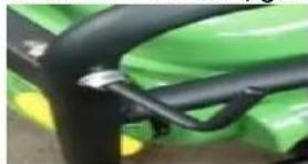
Close-up of a mechanical assembly with pipes and a green circular component (no visible text or symbols)Handle in Down Posion
natural_image
Close-up of a mechanical component with metallic pins and a green base (no visible text or symbols)Locking Pin
natural_image
Close-up of a mechanical device with black lever and green component (no visible text or symbols)Locked in up posion
natural_image
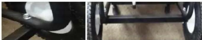
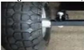
Close-up of a black mechanical component with a metallic screw and tire, next to a larger wheeled vehicle chassis (no visible text or symbols)-
Install the Axle with 2 Bolts and Nuts Pre-Drilled
-
Install the Wide Pneumac Wheels and Tires with Nyloc Locking Nut provided.
natural_image
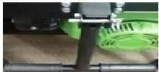
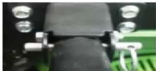
Close-up of two wheels with visible tire and wheel rim, no text or symbols present- Install the wand, gun brackets and hose bracket in the pre-drilled holes with nuts and washers provided.
natural_image
Close-up of a black cable or wire attached to a green plant stem (no visible text or symbols)Top Wand Bracket
natural_image
Close-up of a black curved object attached to a dark surface, possibly a tool or device (no visible text or symbols)Boom Wand Bracket
Hose Bracket
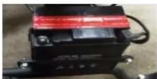
natural_image
Close-up of a black battery with red LED and mechanical components (no visible text or symbols)- Baery Installaon Electric Start Models. The Baery box is located on the frame rail. Install Red (Hot) Lead to Posive Post and Black (Ground) to Negave Post pre wired to the electric starter on the engine.


Pre-Operang Instrucons: Assembly
WHEEL KIT INSTALLATION: Wheels are installed under engine; Support feet are installed under pump end of base for LFQ 2565, for LFQ2865, LFQ3370, and LFQ3370E wheels are under pump and legs under engine.
NOTE: Install Wheel Kit BEFORE Filling the Pressure Washer with Fuel or Oil. Never Tipa Unit that contains Fuel or Oil.
- Carefully tip pressure washer so the Handle is touching the ground and the pump is facing the sky. For LFQ2865 and LFQ3370 the Handle End should be facing the sky and the pump end the ground.
- Using two 12mm Bolts, attach one Heavy-Duty Rubber Leg to the base of pressure washer. Securely
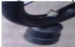
natural_image
Close-up of a black rubber plug with a metallic screw (no text or symbols visible)tighten using 12mm Ratchet and Socket or like tools.
- Repeat Step 5 to attach the second Heavy-Duty Support Leg.
- Carefully tip the pressure washer so the back of the handle is facing the sky and the pump is facing the ground. For LFQ2865 and LFQ3370 the pump end will be facing the sky, the handle end down.
- Using two 12mm Bolts, attach Axle. Securely tighten using 12mm Ratchet and Socket or like tools.
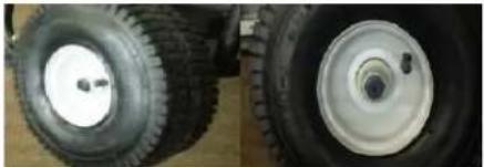
natural_image
Close-up of a tire with visible mesh texture and a black rod inserted (no text or symbols)- Slide 1in. Washer onto each end of the Axle.
- Slide Wheel onto each end of the Axle.
- Securely tighten 18mm Nut to each Axle using 18mm Ratchet and Socket or like tools. For LFQ2865
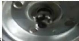
natural_image
Close-up of a metallic mechanical component with central bore and flange (no visible text or symbols)and LFQ3370 use included Nyloc wheel nut retainers
-
Slide Cotter Pin through hole on each end of Axle. Bend the ends of the Cotter Pin to ensure the Cotter Pin will not slip out.
-
Carefully stand the pressure washer up with the wheels and support legs touching the ground.


Pre-Operang Instrucons: Assembly
ADDITIONAL INSTALLATION:
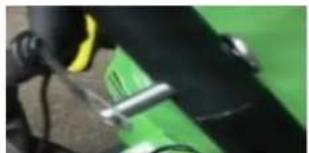
- Slide the Spray Gun & Hose Bracket through the holes on the Handle. Securely tighten using the 14mm nuts and a 14mm Ratchet and Socket or like tools.
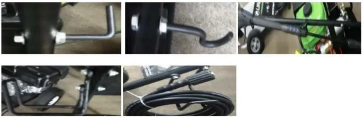
- Screw the Lance w/adjustable spray nozzle and Gun together to form Spray Gun. (Refer to picture below.)
- Place Spray Gun on the Spray Gun & Hose Bracket.
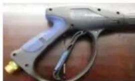
natural_image
Close-up of a gray handheld spray gun with attached cable and connector (no visible text or symbols)Gun
natural_image
Close-up of a handheld water spray gun on a wooden surface (no text or symbols visible)Assembled Gun and Wand w/Adjustable Hose Spray Nozzle Hi-Pressure
natural_image
Coiled black cable or hose with coiled ends, lying on a wooden surface (no text or symbols visible)Hose
natural_image
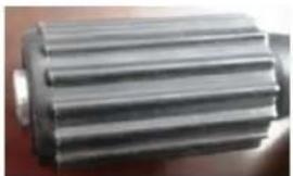
Close-up of a metallic gear or shaft component (no visible text or symbols)Connection Pump - Gun


Pre-Operating Instructions: Engine Oil Level Check

CAUTION:
• Running engine with insufficient engine oil can cause severe damage to the engine.
- The engine performance and service life is directly dependent of the quality of the engine oil. Do NOT use contaminated engine oil or vegetable oil.
- Check engine oil level only with engine stalled and with unit on level ground.
• Use 4-Stroke Gasoline Engine Oil equivalent in quality with SF, SG from API.
Oil velocity varies with average environmental temperature. Select engine oil with proper velocity using the chart to the right in accordance with you regional environmental temperature.
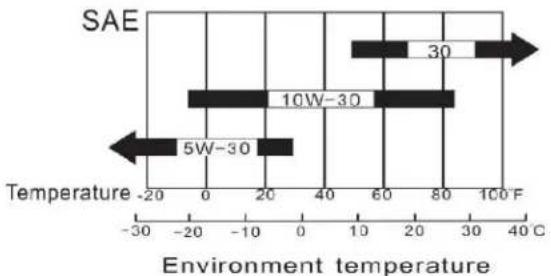
bar
SAE | Temperature Range | Value | | :--- | :--- | | 5W-30 | -20 | | 10W-30 | -10 | | 30 | 80 | | 40 | 60 | | 50 | 30 | Environment temperature Temperature -20 -30 °C Environment temperature 40°CEngine Oil Alarm System
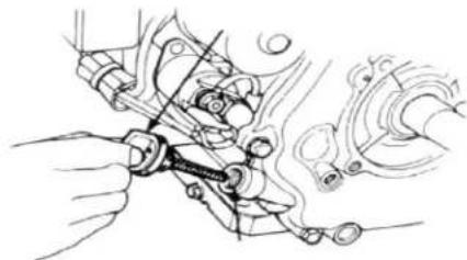
The engine oil alarm system aides in avoiding engine damage due to improper amounts of engine oil in the crankcase. Before the engine oil level in the crankcase drops below the safety line, the engine oil alarm system will automatically stall the engine (while the engine switch remains in the "ON" position).
natural_image
Technical line drawing of a mechanical assembly with hands operating a tool (no text or symbols present)If the engine stops and will not restart:
- Remove the engine oil dipstick and wipe it clean.
- Insert the dipstick into engine oil filler hole without screwing it in
- Remove dipstick and check engine oil amount.
- If engine oil is below required amount, fill specified engine oil up to the top of filler hole. Use engine oil depended on environmental temperature.
- Reinstall the engine oil dipstick.
natural_image
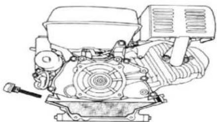
Technical line drawing of a mechanical engine assembly (no text or symbols)

Pre-Operating Instructions: Engine Fuel Level Check

CAUTION:
• Gasoline is extremely flammable. Keep away from ignition sources.
• Fuel unit only in well-ventilated areas with the engine stalled.
• Do NOT smoke near unit.
- Do NOT spill fuel out of the fuel tank. Spilled gasoline and gasoline vapor may ignite. If gasoline is spilled, wipe completely dry before starting the engine.
- Avoid repeated or sustained breathing of gasoline fumes.
- Avoid skin contact with gasoline.
- Keep out of reach of children and pets.
- Do NOT use contaminated gasoline. Keep dirt, dust, and water out of fuel tank.
• After fueling is complete, ensure fuel filler cap is securely fastened.
。
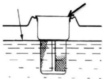
TO CHECK ENGINE FUEL LEVEL:
- Remove fuel filler cap.
- Visually check fuel level within gas tank.
- If too low, add fuel. Do NOT fill above the shoulder of the fuel strainer. Use only unleaded automotive gasoline with an Octane level of 87 or higher.
natural_image
Diagram of a container with liquid and an arrow indicating flow or movement (no text or symbols)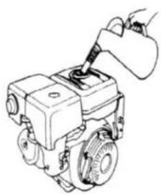
natural_image
Line drawing of a mechanical device with a hand using a tool to inspect or install a component (no text or symbols present)BLENDED FUELS
Gasoline is sometimes blended with alcohol or an ether compound to increase the octane level. If blended fuels are used, ensure the octane rating is at least equal to the recommended octane level in the product specifications. The following three blended fuels recommended:
- Ethanol (ethyl or grain alcohol) – Gasoline containing 10% ethanol by volume.
- MTBE (methyl tertiary butyl ether) – Gasoline containing no more than 10% MTBE by volume.
- Methanol (methyl or wood alcohol) – Gasoline containing no more than 5% methanol by volume.
。
NOTE: Damage caused by the use of blended fuels is NOT covered under warranty.

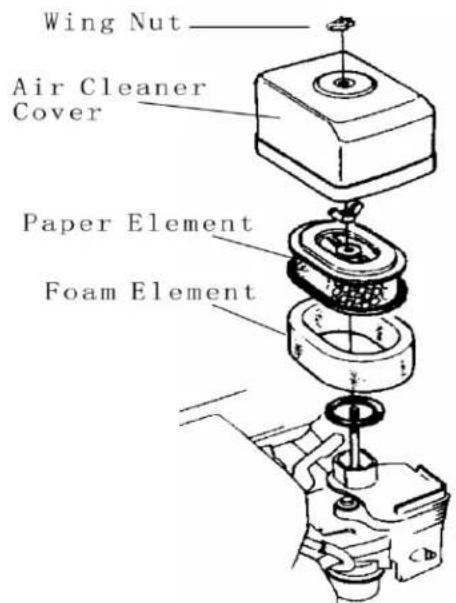
Pre-Operang Instrucons: Air Cleaner Element Check

CAUTION:
- Do NOT run the engine without air cleaner element installed. Operation of engine without air cleaner element installed will result in the inhalation of dirt, dust, and other debris into the engine and through the carburetor. This will result in premature wear of the engine.
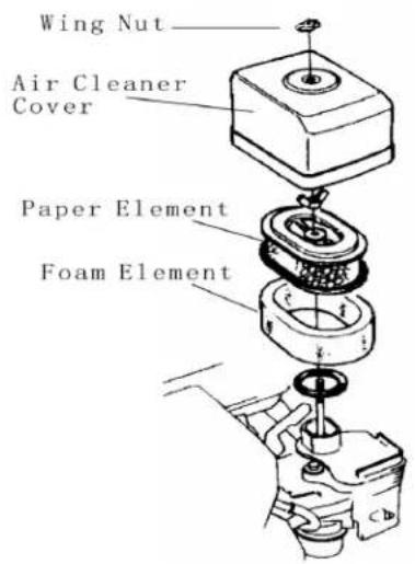
To Check Air Cleaner Element:
- Remove the wing-nut from the top of the air ilter housing and remove top.
- Remove the wing nut from the air ilter and check for debris or stoppage. If dirty replace with the correct Air Filter for your unit. They are available at your dealer or from LIFAN Power USA. Order your il ter by calling toll free 866-471-7464.
- Re-Install the air il ter element into the air il ters housing and re-attaché the air box top, tighten wing nut to irm .
Pre-Operang Instrucons: Connecng Inlet/Outlet/Chemical Injector Hose

CAUTION:
- Use only provided hoses or replacement hoses equal in quality. Use of Improper hoses may result in injury. Check hose for warn spots or leaks.
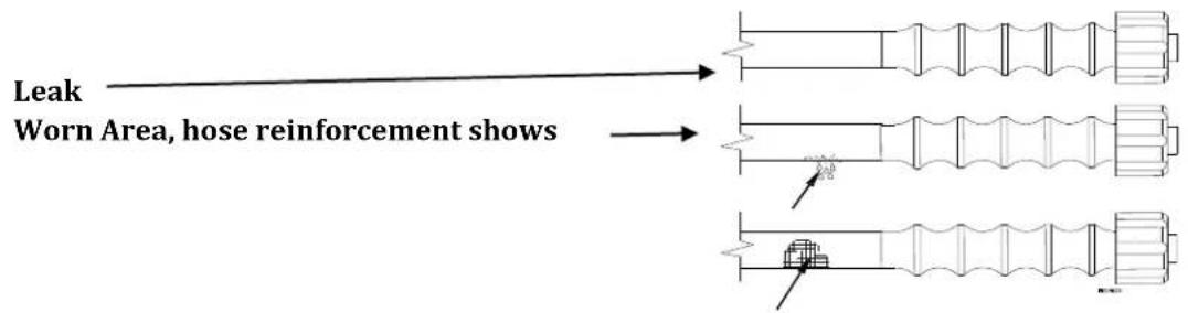
- Use of chemical hose required only if cleaning agents are applied during washing. Adjustable spray wand must be adjusted to least pressure to siphon chemicals.
- Ensure each hose connection is tightly secured. Failure to do so may result in injury or damage to the unit.
•
Chemical Injector Connection
natural_image
Mechanical component with brass fittings and black housing, no visible text or symbolsOutlet Hose Connection
Inlet Hose Connection

Pre-Operating Instructions: Connecting Inlet/Outlet/Chemical Injector Hose
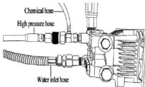
CONNECTING INLET HOSE:
- Connect Inlet Hose to Inlet Hose Connection on Pump or on panel. Tighten Securely.
- Connect alternate end of Inlet Hose to a water tap. The water tap must deliver at least 20 psi (pounds per square inch).
- An insufficient water supply will damage your pump. Make sure the water supply is steady and is 20% over the rated flow of your pump NOTE: Under NO circumstance should the pressure washer be used as a self-prime from a water vessel.
CONNECTING OUTLET HOSE: Outlet Hose must be a High Pressure Hose. NOTE: The Outlet Hose (High Pressure Hose) provided is the BLACK Hose. The outlet or high pressure hose must be checked for any wear or leakage. Replace any damaged high pressure hoses.
- Connect the Outlet Hose to Outlet Hose Connection on Pump or on panel. Tighten Securely.
- Connect alternate end of Outlet Hose to Spray Gun as shown below. Tighten Securely

natural_image
Technical line drawing of a mechanical component with arrows indicating direction (no text or symbols)
Pre-Operang Instrucons: Connecng Inlet/Outlet/Chemical Injector Hose
CONNECTING CHEMICAL INJECTOR HOSE: Water to Chemical ratio is 7:1. NOTE: The Chemical Injector Hose provided is the white/clear hose and should be used in unison with the Spray (black) Nozzle.
CAUTION: WHEN USING CHEMICALS OR CLEANING SOLUTIONS:
• Use low pressure setting only for chemicals.
• Use ONLY soaps and chemicals designed for pressure washer use.
- Do NOT use bleach.
- Ensure water to chemical ratio is 7:1.
- Ensure chemicals are NOT allowed to remain in pump after use. Failure to clean chemicals out of pump will damage unit and void warranty.
-
Connect the Chemical Injector Hose to the Chemical Injector Connection on Pump. Tighten Securely.
-
Place alternate end of Chemical Injector Hose into chemical/cleaning solution to be used. This end of the Chemical Injector Hose will have a ilter to keep foreign debris from entering pump.
-
After use of Chemicals/Cleaning Solutions, place the end with the ilter of the Chemical Injector Hose in clean water and allow to operate for three (3) minutes to clean excess chemicals from pump housing.
4.
NOTE: Chemicals will NOT siphon while Spray Wand is in High-Pressure settings.


Pre-Operang Instrucons: Baery Specicaons
(Electric Start (E) Models Only)
The Battery is NOT included with your Energy Storm Generator. These units require an Acid Cell Battery. This battery is used in many applications, such as lawnmowers, ATV's, motorcycles, etc. and can be found at many retailers and dealers including where you purchased this Power Equipment Product. Use the “Battery Specifications” chart below to attain the specifications of the necessary battery. Or, use the “Cross Reference Models” chart below to match up with the manufacturer's model number with the brand battery available at your local retailer.
| BATTERY SPECIFICATIONS | ||||
| Generator Model | Length (inch) | Width (inch) | Amp (hrs) | DC Voltage (Volts) |
| LFQ2565 | 5.25 in | 3 in | 10 | 12V |
| LFQ2865 | 5.3125 in | 3.1875 in | 12 | 12V |
| LFQ3370 | 5.3125 in | 3.1875 in | 12 | 12V |
| CROSS REFERENCE MODELS | ||
| Generator Model | Manufacturer | Model Number |
| LFQ2565 | Super Start® | CB9B |
| LFQ2865 | Excide® | 12N12A-4A-1 |
| LFQ3370 | Excide® | 12N12A-4A-1 |
Note: (-CA) or (E) Models have same Ba ery Specificaons
| Warning | |
| Follow all the baery manufactures' warnings for proper installing of your baery in order to prevent damage to personnel or equipment. | |
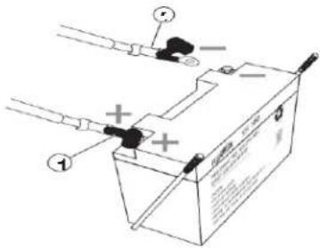
- Battery leads consist of a Red (hot) lead that connects to the (+) battery post and is connected to the (+) terminal on the starter sole noid and a Black lead which is connected to the (-) negative battery terminal and the frame mounting bolt.
- Connect the Red (hot) terminal to the battery.
- Connect the Black (negative) terminal to the battery.

Operaon of Pressure Washer
Pressure Washer Use Location:
WARNING!
Running pressure washer gives off carbon monoxide gas. It is odorless, colorless, and highly toxic.
Breathing carbon monoxide gas can leads to fainting, nausea or may result in death.
only operate pressure washer outdoors.
• Prevent exhaust gas from entering, through windows doors or ventilation intakes, any confined areas.
• DO NOT operate pressure washer inside any enclosed or roofed areas.
BEFORE OPERATING PRESSURE WASHER: Refer to Pre-Operating Instruction section for additional procedures and definitions.
- Check pressure washer condition.
a. Inspect for signs of damage, oil or fuel leaks.
b. Remove excessive dirt and/or debris from the unit.
- Check Inlet, Outlet, and Chemical Injection Hoses.
a. Inspect general condition of hoses to ensure hoses are in serviceable condition.
i. Outlet Hose must be constructed to withstand High-Pressure.
b. Ensure hoses and nozzles are securely installed.
- Check the Engine.
a. Ensure proper engine oil amount.
b. Ensure air cleaner element is clean and installed.
c. Ensure proper fuel level amount.
- Ensure pressure washer is on a level surface.
- Ensure engine switch is in the "OFF" position.
- Ensure pressure washer is at least 7ft away from building walls and other equipment during operation. Do NOT place lammable objects close to pressure washer.
- Always operate within the length of your water hose for inlet pressure.
- Do not operate with any tarps, covers, and any objects on top of the unit.
- Exhaust gas is hot and can cause combustible materials around your unit to ignite, make sure unit is not operated within 7 feet of any combustible materials and always keep a properly charged ire extinguisher and be familiar with the use of the ire extinguisher.

Operaon of Pressure Washer
STARTING THE ENGINE:
Do not run Pressure Washer without proper inlet water supply to high pressure pump and for more than 1 minute without depressing trigger on gun to circulate water to avoid damaging pump.
Refer to the Controls and Features section for additional diagrams and deinitions.
- Depress the Spray Gun trigger.
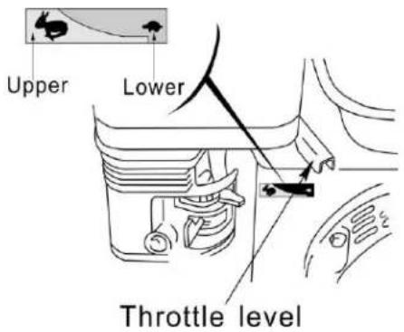
- Move the fuel cock to the "ON" position.
- To start a cold engine, place the choke lever in the "OFF" position. For LEVER mounted choke pull to choke. To restart a warm engine, leave the choke level in the "ON" position. For panel mounted choke models push to run or to start a warm engine.
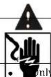
- Move the throttle valve lever away from the "LOWER" position, about 1/3 of the way toward the "UPPER" position.
- Place the throttle lever halfway between the "UPPER" and "LOWER" settings.
- Place the engine switch to the "ON" position.
- Pull the recoil starting handle lightly until resistance is felt, then pull briskly. Do NOT allow the starter handle to snap back against the engine. Return it gently to prevent damage to the starter.
- For electric start models, equipped with a key switch turn the switch to the ON position, for models with the rocker switch start, push the rocker switch to the ON position. Hold the key in the start position or the rocker arm in start position until the engine starts or for no more than 10 engine rotations. If the engine does NOT start, wait 15 seconds and repeat starting procedures.
- After starting the engine, move the throttle lever to the "UPPER" position for self-priming.


Operaon of Pressure Washer
PRESSURE WASHER OPERATION:

CAUTION:
- Avoid contact of high-pressure water exiting spray gun with humans or animals. See "Rules for Safe Operation" for medical information.
- Use proper pressure setting to avoid damage of cleaning surface. - Point tip of spray gun toward cleaning surface and depress trigger.
Do not run Pressure Washer without proper inlet water supply to high pressure pump and for more than 1 minute without depressing trigger on gun to circulate water to avoid damaging pump.
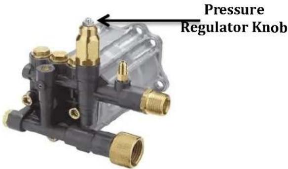
ADJUSTING PRESSURE OUTPUT: The pressure setting is preset at time of manufacturing to provide optimum pressure and cleaning.
TO LOWER PRESSURE:
- Increase the distance between the Spray Gun and the surface being cleaned.
- Reduce the speed of the engine by moving the throttle lever toward the "LOWER" setting.
- Adjust the adjustable spray tip to a wider water fan and less pressure.
- Adjust the Pressure Regulator Knob on the pump. Turn counterclockwise to lower pressure output. After use, return the Pressure Regulator Knob to its original position.


Operaon of Pressure Washer
STOPPING THE ENGINE:
Refer to the Controls and Features section for additional diagrams and definitions.
IN EMERGENCY:
- Turn the engine switch to the "OFF" posion.
- Turn the inlet water supply to the "OFF" position.
- Depress gun trigger to expel remaining pressurized water.
NORMAL PROCEDURE:
- If the chemical injection hose was used with chemicals, allow pressure washer to operate for three (3) minutes while in-taking clean water through chemical injection hose.
- Move the throttle valve lever to the "LOWER" position.
- Turn the engine switch to the "OFF" position.
- Turn the fuel cock to the "OFF" position.
- Depress the spray gun trigger.


Transporng and Storing the Unit

CAUTION:
- To avoid ire, allow unit to cool down for at least twenty (20) minutes before transporting or storing the unit.
• Always transport and store the unit with the fuel cock in the "OFF" position. - Always keep unit in horizontal position to the ground to prevent fuel from spilling. Spilled gasoline and gasoline vapor may ignite.
• Gasoline is extremely lammable and explosive.
STORING THE PRESSURE WASHER: Refer to the Controls and Features section for additional diagrams and deinitions.
- Ensure the storage site for the unit is clean and dry.
Before long term storage of your power equipment product, typically 30 days or more, perform the following:
-
Set the fuel cock (valve) to the "OFF" position.
-
Let the unit continue to run until it stops itself, burning all of the fuel in the fuel system. Keep inlet water supply to pump and continue to use the spray wand with the trigger depressed to keep water circulating in the pump and to expel pressurized water.
-
Turn the ignition switch to the "OFF" position.
-
D rain the engine oil in accordance with the "Engine Oil Change Procedures" in this Owner's Manual's Maintenance section. Do NOT re-ill with oil until ready to use again.
-
Remove the Spark Plug in accordance with the "Spark Plug Maintenance" in the Owner's Manual's Maintenance section. Spray a lubricant, such as WD40®, into the Spark Plug hole to lubricate the top of the piston and walls of the cylinder. Replace the Spark Plug.
-
Pull starter rope until resistance is felt. This will place the valves in the closed position.
-
Add the recommended amount of fuel stabilizer, in accordance with the amount recommended by the manufacturer of the fuel stabilizer, to the unused gasoline left in the unit's tank.
-
Place the unit in a clean, dry, and secure location.
-
Cover the unit to protect from dust.
-
If stored in freezing conditions you can utilize a short garden hose and a funnel to install anti-freeze into the inlet connection on the pump.


Maintenance
| MAINTENANCE SCHEDULE | |
| PROCEDURE | TIME |
| Engine Oil Check | Each Use |
| Replace Engine Oil | Aer Each 40 Hours of Use (For Inial Break in – Aer First ( 1^st 10 Hours of Use |
| Air Cleaner Filter | Check Each Use/Replace As Needed or Aer Every 100 Hours of Use |
| Impeller Check | Aer 300 Hours of Use or Aer First Year |
| Air Cleaner Wash | When Needed or Max 50 hrs run me |
| Spark Plug | When Needed or Max 100 hrs run me |
| Valve Clearance | Check & Re-adjust annually or after 300 Hours of Use |
| Fuel Tank | Replace Every 3 Years Based on Condion |
NOTE: Refer to Following Procedures for Proper Method to Perform Maintenance

Maintenance
ENGINE OIL CHANGE PROCEDURES: Do not run without proper water supply to high pressure pump to avoid damaging pump.
Periodic Maintenance of your engine oil should be performed after each 40 hours of use of you Power Equipment Product. Check your engine oil level prior to each use.
- Start your engine and let it warm up to get the oil warm and thinner. After warm up turn engine off. Be sure during warm up sufficient inlet water is supplied to unit and gun trigger is depressed to avoid damage to the pump. Remove the dipstick (Refer to Controls and Features section) by turning counter clockwise. Remove the oil drain plug (Refer to Controls and Features section) located below the dipstick utilizing the appropriate tools. During warm up on pressure washer always supply inlet water and depress spray gun to circulate water in pump to avoid damage to pump.
CAUTION: THE OIL MAY BE HOT
- Drain the engine oil into an approved receptacle and discard in accordance with all Federal and State Regulations. Never dump your used engine oil on the ground or into drains, only discard in an approved manner. Check with your local authorities to determine the regulations in your area.
WARNING! AVOID SPLASHING OF HOT OIL; IT CAN BURN YOU AND CAUSE SEVERE INJURY.
-
After oil is completely drained, replace oil drain plug and tighten with appropriate tools. Replace oil with the proper oil for your product. Refer to the Pre-Operating Instructions: Engine Oil Level Check section for exact ill requirements. Always use your dipstick to check the oil level and only ill to the full mark on the dipstick. Never overill the engine, as this can cause damage to the unit and void warranty.
-
Replace the dipstick on your engine.
PROPER MAINTENANCE OF YOUR UNIT WILL INCREASE THE LIFE OF YOUR PRODUCT. THE OIL MUST BE CHANGED ON A REGULAR BASIS FOR PROPER OPERATION, AND RELIABILITY AND TO ALSO MAINTAIN YOUR WARRANTY ON THIS PRODUCT.

Maintenance
AIR CLEANER MAINTENANCE:
-
Remove the clip (item 9 in "Air Cleaner A" below) or the wing nut (item 7 in "Air Cleaner B" below) to remove and check the air filter element.
-
For Sponge Type Air Filters, wash with soap and water when contaminated. Squeeze excess liquid from air ilter element, and allow the air ilter element to dry. For Paper Type Air Filters, replace with the correct Air Filter for your unit. They are available at your dealer or from LIFAN Power USA. Order your il ter by calling toll free 866-471-7464.
-
Re-Install the air il ter element into the air il ters housing.
Air Cleaner and Filter Cartridge (Call Lifan Power USA for replacement air ilter cartridge's or visit your retailer)


Maintenance
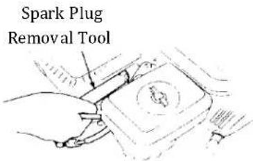
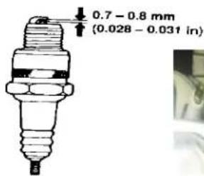
SPARK PLUG MAINTENANCE:
- Remove Spark Plug Cap.
- Remove Spark Plug with socket and handle supplied with your unit.
- Clean any carbon build-up around the Spark Plug.
- Check the Spark Plug Gap and adjust if necessary. 0.028-0.031inch gap.
- Lub ricate the threads of the spark plug with anti-seize compound or engine oil.
- Re-install the Spark Plug and Spark Plug Cap.
natural_image
Close-up of mechanical components with no visible text or symbols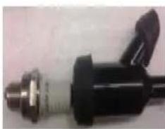
natural_image
Close-up of a black mechanical component with metallic fittings and a handle (no visible text or symbols)FUEL SYSTEM MAINTENANCE:
NOTE: Periodically you can get sediment or trash in your Carburetor Bowl. Use the following procedures to clean:
- Turn the fuel cock (valve) to the "OFF" Position.
- Remove the carburetor bowl by removing the mounting bolt located at the bottom of the bowl.
- Dump out the old fuel and sediment into an approved container
- Clean carburetor bowl thoroughly.
- Fi t a new rubber washer into place and re-attach fuel bowl to the carburetor. NOTE: Removal of the drain screw at the bottom of the bowl can drain the fuel to remove smaller debris that has collected in the bowl.
- After bowl is securely back in place, turn the fuel cock to the "ON" position for use. Units equipped with a pre-il ter for fuel will have a il ter housed just below the fuel cock. Remove the fuel il ter element and clean or replace the fuel il ter element (diagram below).
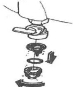
natural_image
Illustration of a hand using a tool to disassemble or attach a mechanical component (no text or symbols visible)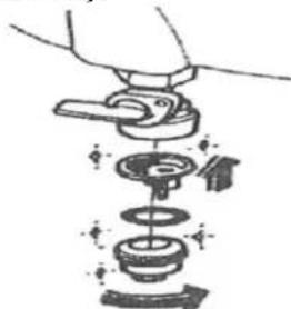
natural_image
Illustration of a hand using a tool to lift a mechanical component (no text or symbols visible)Fuel Filter Element Removal Fuel Filter Element Assembly


Maintenance
Muffler Maintenance: Every 50 hrs of operation remove the "Spark Arrestor" per the diagram below and clean or replace.
natural_image
Technical line drawing of a mechanical device with no visible text or symbols
ANNOVI REVERBERI AXIAL CAM PUMP:
Unit undergoes extensive testing at the time of manufacturing. Lifetime oil is installed in pump and pump is sealed. Pump oil will NOT have to be checked or changed. Pump under warranty by manufacturer. Refer to Warranty Policy for details.
Do not run Pressure Washer without proper inlet water supply to high pressure pump and for more than 1 minute without depressing trigger on gun to circulate water to avoid damaging pump.
USAGE IN HIGH ALTITUDE REGIONS:
In regions with high altitude, the standard carburetor produces overly dense combinations of fuel and air, which result in decreased engine performance and increased fuel consumption. To maintain high engine performance at high altitudes, install a high altitude carburetor main spray nozzle and re-adjust the adjusting screw for idle speed. For usage in regions with an altitude of over 4,527ft (1380m), contact your dealer to replace the standard carburetor and make needed adjustments in advance. Even with a proper high altitude carburetor spray nozzle installed in the engine, the power output of the engine will drop about 3.5% with every 1000ft (305m) increase in altitude. If the standard carburetor jets are not replaced and adjusted for usage in high altitude, the increased altitude effect will be even more severe.
NOTE: Usage of the water pump in regions with lower altitude than the high altitude carburetor spray nozzle is applicable, may result in decrease of engine performance. The engine may become overheated and over-lean combination of fuel and air produced, may cause severe damage to the engine.


Troubleshoong
IF THE ENGINE WILL NOT START:
- Check to ensure switches are in the "ON" position.
- Check engine oil level. The unit possesses a Low Oil Shutdown feature that will not allow your engine to start if the oil is below safe operating levels. This feature is installed to increase the life of your engine and prevent engine damage. If oil level is low, ill to the full mark on dipstick. Refer to the Pre-Operating Instructions: Engine Oil Check section for exactoil type and amounts.
- Check the fuel level to insure adequate fuel. Add fuel if necessary.
- Remove and inspect the spark plug for cleanliness and proper electrode gap. If needed, clean or replace the spark plug. Refer to Spark Plug Maintenance in the Maintenance section of the Owner's Manual for proper procedure.
- If the unit will still NOT start after performing the above checks, call our customer hotline at LIFAN Power USA Toll Free 1-866-471-7464 or take the unit to an authorized Service Center.
NOTE: Periodically on the initial start-up or after the unit has been stored for a long period of time, the location your "Low Oil Shutdown" system will stick to the bottom of the oil pan. Locate the two (2) wires to the Low Oil Sensor Diode (i gure "Low Oil Sensor Diode" to the right) located on the side of the engine block. Unplug these wires and, only after ensuring the engine is full of oil, start the engine and allow to run until warm (normally 20 minutes, as this will heat the oil and release the float on the Low Oil Shutdown System). Then re-plug the wires to the terminals on the Low Oil Shutdown Sending Unit.
IF WATER IS LEAKING:
• Ensure Outlet Hose is securely tightened.
- Ensure Inlet Hose nut is securely tightened.
- Call dealer for repair if pump housing is leaking.
IF ABNORMAL NOISE FROM PUMP HOUSING:
- No water inside pump – Ensure Inlet Hose is connected and supplying recommended supply of water to pump. Check to see if the inlet hose is kinked.
IF NO WATER EXITING FROM SPRAY WAND:
- Ensure Inlet Hose is NOT clogged or kinked.

Pressure Washer Safety
- Never operate a gasoline engine powered product in any enclosed spaces, as they product deadly Carbon Monoxide Poisonous Gases.
- Do NOT operate your power equipment in inclement weather such as rain, snow, and/or sleet.
- Do NOT operate your power equipment within seven (7) feet of any lammable materials.
- When refueling your power equipment never smoke or refuel near any flame or ignition devices. Never refuel while the unit is running. If during the refueling process some fuel is spilled, always completely clean the fuel and allow sufficient drying time prior to re-starting your unit. Gasoline vapors ignite easily and are very dangerous.
- NEVER ALLOW CHILDREN OR ANIMALS TO BE NEAR THIS EQUIPMENT DURING OPERATION. ONLY QUALIFIED PERSONS SHOULD OPERATE THIS EQUIPMENT. PLEASE FOLLOW ALL GUIDELINES CONTAINED IN THIS OWNER'S MANUAL FOR THE SAFE OPERATION OF THIS EQUIPMENT.

Safe Operaon
Follow Safety Rules for Operation
After you have checked and fueled the equipment and positioned it in a suitable worksite, it is time to start your pressure washer. The following are the procedures necessary for safe, successful operation of your pressure washer.

WARNING
Failure to follow safety rules may result in serious injury or death to the operator or bystanders.
Instruct operators. Owner must instruct all operators is safe set-up and operation. Do not allow anyone toperate the pressure washer who has not read the Owner's Manual and been instructed on safe use practices.
Safety equipment/controls. Always operate with all safety covers, guards, and barriers in place and in good working order, and all controls properly adjusted for safe operation.
Moving parts. Keep hands, feet, hair and apparel away from moving parts. Air vents may cover moving parts and should be avoided as well. Never remove an guards while the unit is operating.
Ear Protection. Hearing can be damaged from prolonged, close-range exposure to the type of noise produced by this pressure washer. The use of ear plugs or other hearing protection device is recommended for persons working within 15-20 feet of the running pressure washer for an extended period of time.
Eye Protection. Wear ANSI/OSHA required "Z87.1" safety glasses when operating or servicing the pressure washer. Pressurized spray from this unit can cause severe injury to the eyes. Small objects can become airborne as the spray contacts them
NOTE!
Before starting the pressure washer, review the following general safety rules for operation:
Conditions for Use
Know how to stop. Be thoroughly familiar with proper use of the equipment and all controls and connections. Know how to stop the pressure washer and depressurize system quickly if needed.
Instruct all operators The pressure washer's ownemust instruct all operators and potential renters in safet-up and operation. Do not allow anyone to operate the pressure washer who has not read the Owner Manual and been instructed on its safe use.


Safe Operaon
Adult control only Only trained adults should set up and operate the pressure washer. Donotletchildren operate.
Pressure washers can generate forces greater than children can control and require judgment beyond what can be expected of children.
Under the influence. Never operate, or let anyone else operate, the pressure washer while fatigued or under the influence of alcohol, drugs, or medication.
Safety equipment / controls in place Do not operate the pressure washer unless all safety covers, guards and barriers are in place and in good working order, and all controls are properly adjusted for safe operation.
Damaged. Do not operate the pressure washer with damaged, missing, or broken parts. Never attempt to repair a high pressure hose or component. Always replace it with a part that is rated at or above the pressure rating of the machine.
Modifications. Do not modify the pressure washer any way or deactivate any safety device. Do not change or add to fuel tank, fuel lines, or exhaust system.
Modifications can result in hazards related to carbon monoxide poisoning, fuel leaks, ire, explosion or other serious safety hazards, and will also void the warranty.
During Use
Stay alert. Watch what you are doing at all times.
Clear work area Clear the work area of all bystanders.
Keep children and pets away.
Keep spray away from electrical wiringpray contact with electrical wiring will likely result in severe electrical shock or electrocution.
Hot exhaust/partsStay clear of engine exhaust Never touch hot engine mufler, or other hot surfaces. All are very hot and will burn you.
Never pull by hose. Do not move this machine by pulling on the hose. Hose or connections could fail and result in catastrophic high pressure release of fluid as well as hose whipping.
Avoid sharp objects. Keep hose away from sharpobjects. Bursting hoses may cause injury.
No load bearing Do not use the pump to support other items of equipment that impose unacceptable loads or the pump. Do not attempt to use this machine as a prop.
Lock trigger safety latch when not spraying Spray gun is equipped with a built-in trigger safety latch to guard against accidental trigger release. Rotate safety latch to the locked position when not spraying.
Do not run Pressure Washer without proper inlet water supply to high pressure pump and for more than 1 minute without depressing trigger on guy to circulate water to avoid damaging pump.


Safe Operaon
Leaving unattended Always turn off the pressure washer and relieve system pressure before leaving the prayer unattended
Prompt Emergency Response
Seek medical aid for suspected injection injury injured by high-pressure luid, no matter how small the wound is, see a doctor at once. A typical injection injury may be a small puncture wound that does not looserious. However, severe infection or reaction can result if proper medical treatment is not administered immediately by a doctor who is familiar with injection injuries.
Seek medical aid for suspected carbon monoxidøpoisoning. The running engine gives off carbonmonoxide, a poisonous gas that can kill you. If you startofeelsick,dizzy,orweakwhileusingthe pressure washer,shut off the engine and get to fresh air RIGHTAWAY. See a doctor. You may have carbon monoxidøpoisoning.
Put on Personal Protective Gear
WARNING: Personal Protective Gear
Use personal protective gear to prevent:
- Eye and skin injection injury from high pressure spray
- Eye injury from flying debris
- Wear waterproof gloves, safety glasses with side andop protection, face protection, and protective clothing when operating the machine. If spraying pressure washer specific chemicals, wear a respirator mask to avoid inhalation of vapors if directed on the chemical label.
- Wear non-slip, protective footwear. Use of pressure washer can create puddles and slippery surfaces. Wear footwear capable of maintaining a good grip on wet surfaces.
- Wear footwear capable of maintaining a good grip or wet surfaces.


LIMITED WARRANTY POLICY
This warranty is limited to the following Lifan Power and Storm Series products that are distributed by the EquipSource LLC, dba LIFAN POWER USA, located at 2205 Industrial Park Road, Van Buren, AR 72956. Eecve date is 4/20/2010.
| LENGTH OF WARRANTY | ||||
| Residential Use** | Commercial/Rental*** | |||
| PRODUCTS COVERED | 1^st Year | 2^nd Year | 3^rd Year | Warranty not to exceed 300 hrs. Or terms listed below. |
| Walk Behind Mowers | Full unit parts and labor | Full unit parts only | Engine: parts only | Full unit: 3 months parts and labor |
| Water Pumps | Full unit parts and labor | Full unit parts only | Engine: parts only | Full unit: 12 months parts and labor |
| Generators/Inverter Generators | Full unit parts and labor | Full unit parts only | Engine: parts only | Full unit: 12 months parts and labor |
| Pressure Washer Engines | Full unit parts and labor | Full unit parts only | Engine: parts only | Full unit: 12 months parts and labor |
| Pressure Washer Pumps* | Full unit parts and labor | NA | NA | Full unit: 12 months parts and labor |
| Gasoline Engines | Full unit parts and labor | Full unit parts only | Engine: parts only | Full unit: 12 months parts and labor |
| Gasoline Powered Welders | Full unit parts and labor | Full unit parts only | Engine: parts only | Full unit: 6 months parts and labor |
*All Lifan Pressure Pro™ and Storm Series Pressure Storm™ pressure washers are equipped with Annovi Reverberi AR™ high pressure water pumps, which are covered by the manufactures, AR 1 year limited warranty. Go to www.lifanpowerusa.com for details.
** Residential Use is deined as items that are for personal use.
*** Commercial/Rental use is deined as any usage for income producing or other business related uses.
** Engine, pump and frame covered by warranty. Accessories such as hoses, tips and wands are covered for 1 year only.
In order to qualify for the limited warranty the product(s) must be purchased in North America from an authorized EquipSource, LLC d/b/a Lifan Power USA dealer or a dealer authorized by EquipSource to sell Lifan products. This warranty is non-transferable and applies only to the original purchaser. The supplied "Warranty Registration Card" must be completed and on file with American Warranty Service (at the supplied address), at the time that any warranty claim is made. The "Warranty Registration Card" must be submitted with a receipt of purchase which clearly states the date of purchase and where the purchase was made. The purchaser has 30 days from date of purchase to register warranty registration card.
During the warranty period (stated above) EquipSource, LLC and/or American Warranty Service will repair or replace, at its' option, any part that is proven to be defective in material or workmanship under normal usage. Repairs and/or replacement will be made without charge for parts or labor. All parts found to be defective must be returned to EquipSource or American Warranty Service at our direction. Upon reception of the parts a judgment as to the validity of the warranty claim will be determined. All parts replaced under warranty or any replacement of the complete unit will be considered part of the original product and replacement of any product, and any warranty on those parts or replacement unit will coincide with the original warranty.
To obtain Warranty Service, call our Customer Service Hotline at 1-866-471-7464 and press 2 for Warranty Service at which time you will be transferred to the technicians at American Warranty Service. In lieu of this you may call directly to American Warranty Service at 888-926-4313 to be directly connected to a repair specialist.. At Equipsource's discretion; Equipsource may elect to replace a defective unit. In this case the end user is responsible for all shipping and handling charges associated with the exchange and as stated above the warranty will coincide with the date of the original purchased unit.


LIMITED WARRANTY POLICY
This warranty is not valid for products or parts affected or damaged by accident, collision, normal wear, fuel contamination, abuse, neglect, misuse, alteration and/or unsuitable use or unauthorized parts replacement. Mower decks and blades are specifically not warranted for impact or abrasive damage. Warranty becomes void if the customer fails to install, maintain, and/or operate the product in accordance with the instructions and recommended actions of Lifan set forth in the owner's manual. EquipSource, LLC disclaims any responsibility for time loss or loss of usage of the product, transportation, commercial loss, or any other incidental or consequential damage. Prior to any warranty service an approval code must be issued to the service center in order for the warranty claim to be valid. Any implied warranties are limited to the duration of this written limited warranty. This warranty gives you specific legal rights, and you may also have other rights, which may vary from state to state.
This warranty specifically excludes the use of any Lifan Power Equipment or Storm Series power equipment as the "Sole Source of Power" for "off the power grid applications" and this warranty will become null and void for units used for this purpose and manner. This warranty specifically excludes the use of any Lifan Power Equipment or Storm Series power equipment for the purpose of powering Life Support devices, Life Support appliances, Medical devices, and/or Medical appliances. EquipSource, LLC will not be held responsible for any damage due to the use of any Lifan or Storm Series power equipment for these purposes.
Exclusions to Warranty:
- Failure to perform "Periodic Maintenance" as required and specified in the supplied "Owner's Manual."
• Improper repair of product or replacement of parts with non-oem (original equipment manufacturer) parts.
Operation in uses and methods other than those outlined in the "Owner's Manual."
• Service and/or repairs performed by anyone other than an" Authorized Lifan or Storm Series Products Service Center."
More information is also available on our website: www.Lifanpowerusa.com
EquipSource, LLC
Revised
01/15/2015
OWNER'S RESPONSIBILITY
To ensure trouble free warranty coverage it is important that you register your Lifan product by phone at 1-866-471-7464, or by illing out and returning to Lifan Power USA the warranty registration card supplied with your product. Registering your product conirms your warranty coverage and provides a direct link between you and Lifan Power USA if we ind it necessary to contact you.
Your receipt for purchase including date, model and serial number must be maintained and registered to receive service from an Authorized Service Dealer for warranty service. Proof of purchase rests solely with you, the original purchaser.
You must demonstrate reasonable care and use, and follow preventive maintenance, storage, fuel and oil usage as prescribed in the operator's manual for your Lifan Power unit. Should a product difficulty occur, you must, at your expense, deliver or ship your Lifan Power Product unit to a Lifan Authorized Service Dealer for warranty repairs (which must occur within the applicable warranty period), and arrange for pick-up or return of your unit after the repairs have been made. For the warranty assistance from a Lifan Authorized Service Dealer nearest to you, call Lifan's automated phone at 1-866-471-4764 Option 2. Should you require assistance or have questions concerning Lifan Power USA Warranty Statement, you can contact us through the web at www.lifanpowerusa.com or call toll free 1-866-471-7464.

LIMITED WARRANTY POLICY
EXCLUSIONS
- Lifan Power Equipment that utilize non-Lifan replacement parts.
• Costs of normal maintenance and adjustments. - Failures caused by any contaminated fuels, oils, or lack of proper oil levels.
- Repairs or diagnostics performed by individuals other than Lifan authorized dealers not authorized in writing by Lifan.
- Failures due to normal wear and tear, accident, misuse, abuse, negligence or improper use.
- As with all mechanical devices, the Lifan engines need periodic part(s) service and replacement to perform as designed. This warranty will not cover repair when normal use has exhausted the life of a part(s) or engine.
- Failures caused by any external cause or act of God, including but not limited to, collision, theft, vandalism, riot, war, ire, freezing, lightning, earth-quake, windstorm, hail, water, lood, tornado, or hurricane or any occurrence outside of normal use and activity.
- Damage related to any animal infestation to include rodent and/or insect infestation.
- Products that are modified or altered in a manner not authorized in writing by Lifan.
- Any incidental, consequential or indirect damages caused by defects in materials or workmanship, or any delay in repair or replacement of the defective part(s).
- Failure due to misapplication.
- Telephone, cellular phone, facsimile, internet access, or other communication expenses.
- Expenses related to "customer instruction" or troubleshooting where no manufacturing defect is found.
• Overnight freight or special shipping costs for replacement part(s). - Overtime, holiday or emergency labor.
- Starting batteries, fuses, light bulbs and engine luids.

LIMITED WARRANTY POLICY
DISCLAIMER OF IMPLIED WARRANTIES
This limited warranty is in lieu of all other expressed or implied warranties, including any warranty of the units itness for any particular use and any implied warranty of MERCHANTABILITY otherwise applicable to Lifan Power Equipment and its affiliated companies shall not be liable for any special, incidental or consequential damage, including lost proits. There are no warranties extended other thanas provided herein. This limited warranty may be modified only by Lifan Power USA. Any implied warranties allowed by law shall be limited in duration to the terms of the express warranty provided herein. Some states do not allow limitations on how long an implied warranty lasts, so the above limitation may not apply to you. Some states do not allow the exclusion or limitation of incidental or consequential damages, so the above limitation may not apply to you. This warranty gives you specific legal rights. You also have other rights from state to state. Lifan's ONLY LIABILITY SHALL BE THE REPAIR OR REPLACEMENT AS STATED ABOVE. IN NO EVENT SHALL Lifan BE LIABLE FOR ANY INCIDENTAL OR CONSEQUENTIAL DAMAGES, EVEN IF SUCH DAMAGES ARE A DIRECT RESULT OF Lifan's NEGLIGENCE. Some states do not allow the exclusion or limitation of incidental or consequential damages, so the above limitation may not apply to you. This warranty gives you specific legal rights and you may also have other rights from state to state.
OWNER'S WARRANTY RESPONSIBILITIES:
As the outdoor equipment owner, you are responsible for performance of the required maintenance listed in your owner's manual. EquipSource, LLC d/b/a Lifan Power USA recommends that you retain all receipts covering maintenance on your outdoor equipment. Lifan Power USA will not deny your warranty coverage based solely on your lack of receipts for service however. The condition of the equipment upon arrival at the service center will determine the warrantable nature of the product.
As the outdoor equipment owner, you should however be aware that Lifan Power USA may deny your warranty coverage if your outdoor equipment or a part has failed due to abuse, neglect, or improper maintenance or unapproved modifications.
You are responsible for presenting your outdoor equipment to a Lifan Power Equipment Authorized Warranty Service Dealer as soon as the problem exists. The warranty repairs should be completed in a reasonable amount of time, not to exceed 30 days.
If you have any questions regarding your warranty rights and responsibilities, you should contact Lifan Power USA or American Warranty Service Representative at 1-866-471-7464 Option 2 Warranty and Service or at the following address Lifan Power USA, 2205 Industrial Park Road, Van Buren, AR 72956 or by contacting us through www.lifanpowerusa.com.


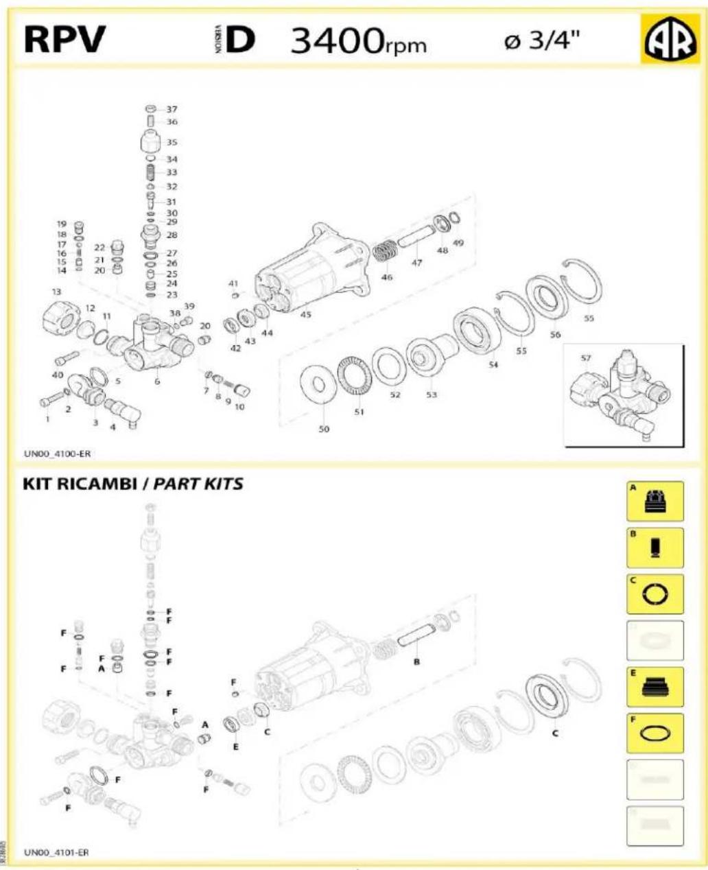
LFQ2565 and LFQ2565E with RPV Pump

| U-Rings | |||||||
| Pos. | Q.ty | Pos. | Q.ty | Pos. | Q.ty | Pos. | Q.ty |
| 2 | 1 | 26 | 1 | ||||
| 5 | 1 | 27 | 1 | ||||
| 7 | 1 | 29 | 1 | ||||
| 14 | 1 | 30 | 1 | ||||
| 18 | 1 | 38 | 1 | ||||
| 21 | 3 | 41 | 1 | ||||
| 23 | 1 | ||||||
KIT RICAMBI - PART KITS
| A=KIT 43025valvolevalves | B=KIT 43026ø12pistonipistons | C=KIT 43027tenute oliooil seals | E=KIT 43028ø12tenute acquawater seals | ||||
| Pos. | Q.ty | Pos. | Q.ty | Pos. | Q.ty | Pos. | Q.ty |
| 20 | 6 | 47 | 3 | 4456 | 31 | 42 | 3 |
| F=KIT 43029ORO-Rings | |||||||
| Pos. | Q.ty | Pos. | Q.ty | Pos. | Q.ty | Pos. | Q.ty |
| 2 | 1 | 26 | 1 | ||||
| 5 | 1 | 27 | 1 | ||||
| 7 | 1 | 29 | 1 | ||||
| 14 | 1 | 30 | 1 | ||||
| 18 | 1 | 38 | 1 | ||||
| 21 | 3 | 41 | 1 | ||||
| 23 | 1 | ||||||
SIMBOLOGIA - SYMBOLS
| Tolleranza coppia di serraggio 0+10% / Tightening torque tolerance 0+10%Avvitare con Loxeal SS-14 / Screw with Loxeal SS-14Lubrificare con grasso Molykote PG54 / Lubricate with grease Molykote PG54Lubrificare con grasso Molykote G807 / Lubricate with grease Molykote G807 | |||
| Olio - Off | |||
| Tipo / Type | Quantità / Quantity | ||
| SAE 15W40 | 0,03 Kg | ||
2

LFQ2865 with RMV Pump
RMV
VERSION D
3400rpm
∅ 3/4"

284 Series
| Pos. | Cod. | Denominazione | Description | Qt | Note | |
| 1 | 380410 | Vite | TCEI M8x40 | Screw | 3 | C=25Nm |
| 2 | 2840022 | Testa | Head | 1 | ||
| 6 | 2840830 | Vite | Screw | 1 | C=10Nm | |
| 7 | 600180 | Guarnizione OR | 7,66 × 1,78 | O-ring | 1 | |
| 8 | 2840481 | Tappo | Plug | 3 | C=15Nm | |
| 9 | 2841530 | Tappo | Plug | 3 | C=25Nm | |
| 10 | 2849051 | Valvola completa | Complete valve | 6 | ||
| 11 | 1470210 | Guarnizione OR | 9 × 1 | O-ring | 1 | |
| 12 | 2840770 | Sede | Seat | 1 | ||
| 13 | 2840760 | Otturatore | Shutter | 1 | C=3Nm | |
| 14 | 820510 | Guarnizione OR | 10,82 × 1,78 | O-ring | 1 | |
| 15 | 2840750 | Guida pistone | Piston guide | 1 | C=20Nm | |
| 16 | 2760210 | Anello | antiestrusione | Ring | 1 | |
| 17 | 660190 | Guarnizione OR | 6,07 × 1,78 | O-ring | 1 | |
| 18 | 2260100 | Guarnizione OR | 6,02 × 2,62 | O-ring | 1 | |
| 19 | 2841140 | Pistone | Piston | 1 | ||
| 20 | 1060120 | Dado | M6 | Nut | 1 | |
| 21 | 392840 | Vite | M6x16 | Screw | 1 | |
| 22 | 2760460 | Inserto | Insert | 1 | ||
| 23 | 1980220 | Piattello | Wobble plate | 2 | ||
| 24 | 2760410 | Molla | Spring | 1 | ||
| 25 | 2200141 | Tenuta acqua | Water seal | 3 | ||
| 27 | 2840561 | Boccola | Bosling | 3 | ||
| 29 | 1683500 | Tenuta olio | Oil seal | 3 | ||
| 30 | 2840230 | Corpo pompa | Pump body | 1 | ||
| 31 | 480560 | Guarnizione OR | 6,75 × 1,78 | O-ring | 1 | |
| 32 | 2840710 | Tappo | Plug | 1 | ||
| 33 | 480480 | Guarnizione OR | 4,48 × 1,78 | O-ring | 1 | |
| 34 | 1982520 | Portagomma | 8 | Hose tail | 1 | C=4Nm |
| 35 | 1250280 | Sfera | Ball | 1 | ||
| 36 | 1560520 | Molla | Spring | 1 | ||
| 37 | 1460431 | Guarnizione OR | 4 × 2,5 | O-ring | 1 | |
| 38 | 2841150 | Otturatore | Shutter | 1 | ||
| 39 | 1343580 | Molla | Spring | 1 | ||
| 40 | 800560 | Guarnizione OR | 8,73 × 1,78 | O-ring | 2 | |
| 41 | 2840340 | Inlettore | Injector | 1 | ||
| 42 | 2840270 | Raccordo | Fitting | 1 | 3/4" NH | |
| 43 | 2841230 | Raccordo | alluminio | Fitting | 1 | C=25Nm |
| 2840390 | Raccordo | ottone | Fitting | 1 | C=25Nm | |
| 44 | 1266330 | Filtro | Filter | 1 | ||
RMV 3400 rpm D version e 3/4"- Alluminium
| Pos. | Cod. | Denominazione | Description | Qt | Note | |
| 46 | 2840400 | Raccordo | 3/8"(M)-M22x1,5(M) | Fitting | 1 | C=25Nm |
| 2841380 | Raccordo | Fitting | 1 | C=25Nm | ||
| 48 | 2840060 | Molla | Spring | 3 | ||
| 49 | 2840040 | Pistone | 12 | Piston | 3 | |
| 50 | 2840050 | Piattello | Wobble plate | 3 | ||
| 51 | 1980130 | Ralla | Fifth wheel | 1 | ||
| 52 | 1980250 | Ralla | Fifth wheel | 1 | ||
| 53 | 1980240 | Ralla | Fifth wheel | 1 | ||
| 54 | 2840900 | Piattello | 11" marcato 7 | Wobble plate | 1 | C |
| 2840720 | Piattello | 12" marcato 5 | Wobble plate | 1 | ■ | |
| 55 | 161060 | Cuscinetto | Bearing | 1 | ||
| 56 | 161050 | Anello | seeger 72 | Ring | 1 | |
| 57 | 2841050 | Anello | tenuta | Ring | 1 | |
| 58 | 2840890 | Guarnizione OR | 14 × 2 | O-ring | 2 | |
| 59 | 2840840 | Lappo | Plug | 1 | C=4Nm | |
| 60 | 480650 | Rondella | Washer | 1 | ||
| 61 | 1060100 | Sfera | Ball | 1 | ■ | |
| 62 | 2840440 | Sede | Seat | 1 | ■ | |
| 63 | 2840450 | Molla | Spring | 1 | ■ | |
| 65 | 2841520 | Guarnizione OR | 13,5 × 1,8 | O-ring | 3 | |
| 66 | 2849284 | Premontaggio testa | Head assembly | 1 | ■ | |
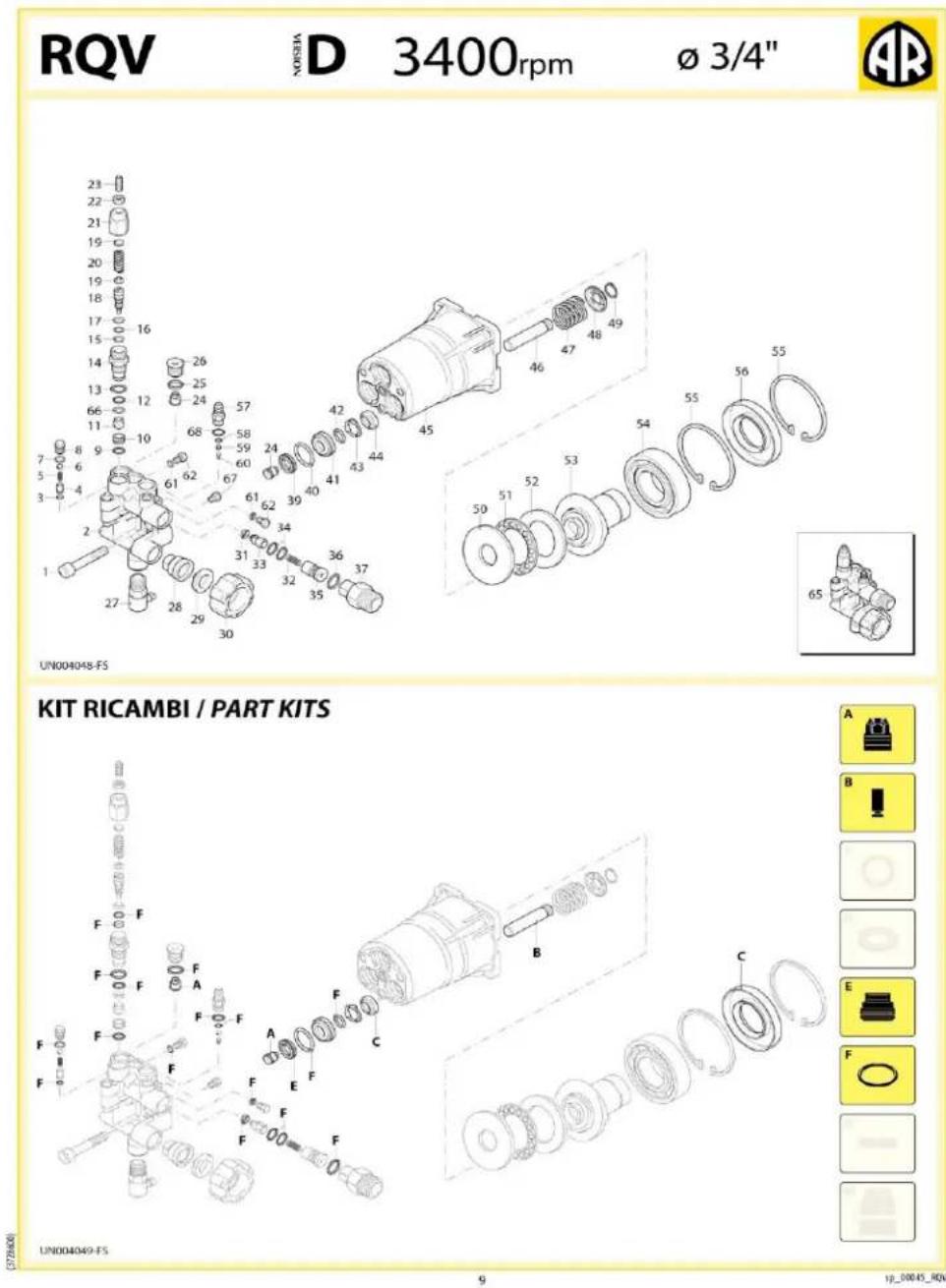
KIT RICAMBI - PART KITS
| A=KIT 2233valvolevalves | B=KIT 2234ø12pistonipitrons | C=KIT 42127tenute ollooil seals | E=KIT 42122ø12tenute acquawater seals | ||||
| Pos. | Q.ty | Pos. | Q.ty | Pos. | Q.ty | Pos. | Q.ty |
| 10 | 6 | 49 | 3 | 2957 | 31 | 25 | 3 |
| F=KIT 2237ORO-Rings | |||||||
| Pos. | Q.ty | Pos. | Q.ty | Pos. | Q.ty | Pos. | Q.ty |
| 7 | 1 | 37 | 1 | ||||
| 9 | 1 | 40 | 2 | ||||
| 11 | 1 | 58 | 2 | ||||
| 14 | 1 | 65 | 3 | ||||
| 17 | 1 | ||||||
| 18 | 1 | ||||||
| 33 | 1 | ||||||
SIMBOLOGIA - SYMBOLS
| Per / For RMV 2 G20 D | Per / For RMV 2.2 G24 D | ||
| Tolleranza coppia di serraggio 0+10% / Tightening torque tolerance 0+10%Avviltare con Loveal 55-14 / Screw with Loveal 55-14Lubrificare con grasso Molykote PG54 / Lubricate with grease Molykote PG54Lubrificare con grasso Molykote GB07 / Lubricate with grease Molykote GB07Avviltare con Loveal 83-55 / Screw with Loveal 83-55 | |||
| Olio - Oil | |||
| Tipo / Type | Quantità / Quantity | ||
| SAE 15W40 | 0,65 Kg | ||
MI 91607
2
sp_0001D_RMV_D_A
(1) 保留误差

1

LFQ3370(E) with RQV Pump

| POS. | Cod. | Denominazione | Description | Qt | Note | Pos. | Cod. | Denominazione | Description | Qt | Note | ||
| 1 | 380410 | Vite | TCEI M8x40 | Screw | 3 | C=20Nm | 44 | 1683500 | Tenuta olio | Oil seal | 3 | ||
| 2 | 3720770 | Testa | ottone | Head | 1 | 45 | 3720790 | Corpo pompa | Pump body | 1 | |||
| 3 | 3720750 | Guamizione OR | ∅ 4x1 | O-ring | 1 | 46 | 3720340 | Pistone | ∅ 12 | Piston | 3 | ||
| 4 | 3720740 | Sede | Seat | 1 | 47 | 3720380 | Molla | Spring | 3 | ||||
| 5 | 3720760 | Molla | Spring | 1 | 48 | 3720360 | Fermo | Lock | 3 | ||||
| 6 | 1250280 | Sfera | Ball | 2 | 49 | 3720390 | Anello | Ring | 3 | ||||
| 7 | 1682800 | Guamizione OR | ∅ 6x1,5 | O-ring | 1 | 50 | 1980130 | Ralla | Fifth wheel | 1 | |||
| 8 | 3720730 | Tappo | Plug | 1 | C=4Nm | 51 | 1980250 | Ralla | Fifth wheel | 1 | |||
| 9 | 1470210 | Guamizione OR | ∅ 9x1 | O-ring | 1 | 52 | 1980240 | Ralla | Fifth wheel | 1 | |||
| 10 | 3720500 | Sede | Seat | 1 | 53 | 2841190 | Piattello | 13" marcato 3 | Wobble plate | 1 | |||
| 11 | 3720520 | Otturatore | Shutter | 1 | C=3Nm | 54 | 161060 | Cuscinetto | Bearing | 1 | |||
| 12 | 3720560 | Guamizione OR | ∅ 4,5x1,5 | O-ring | 1 | 55 | 161050 | Anello | seeger ∅i 72 | Ring | 2 | ||
| 13 | 394280 | Guamizione OR | ∅ 12,42x1,78 | O-ring | 1 | 56 | 2841050 | Anello | tenuta | Ring | 1 | ||
| 14 | 3720620 | Guida pistone | Piston guide | 1 | C=20Nm | 57 | 3700240 | Portagomma | ∅ 8 | Hose tail | 1 | C=4Nm | |
| 15 | 3720570 | Guamizione OR | ∅ 9x1,5 | O-ring | 1 | 58 | 480480 | Guarnizione OR | ∅ 4,48x1,78 | O-ring | 1 | ||
| 16 | 660190 | Guamizione OR | ∅ 6,07x1,78 | O-ring | 1 | 60 | 1560520 | Spring | 1 | ||||
| 17 | 3720600 | Anello | antiestrusione | Ring | 1 | 61 | 3201760 | Guarnizione OR | ∅ 4x1,5 | O-ring | 2 | C=4Nm | |
| 18 | 3720540 | Otturatore | Shutter | 1 | 62 | 3720720 | Tappo | Plug | 2 | ||||
| 19 | 3720660 | Piattello | Wobble plate | 2 | 65 | 3729200 | Premontaggio testa | Head assembly | 1 | ||||
| 20 | 3720640 | Molla | Spring | 1 | 66 | 3720580 | Anello | antiestrusione | Ring | 1 | |||
| 21 | 3720681 | Guida | Guide | 1 | 67 | 3720830 | Tappo | gomma | Plug | 1 | |||
| 22 | 1060120 | Dado | M6 | Nut | 1 | 68 | 3700250 | Guarnizione OR | ∅ 8x1,1 | O-ring | 1 | 80 ShA | |
| 23 | 392840 | Vite | M6x16 | Screw | 1 | ||||||||
| 24 | 2849053 | Valvola completa | Complete valve | 6 | |||||||||
| 25 | 770140 | Guamizione OR | ∅ 11,11x1,78 | O-ring | 3 | ||||||||
| 26 | 3720441 | Tappo | Plug | 3 | C=20Nm | ||||||||
| 27 | 2761380 | Valvola | Valve | 1 | C=16Nm | ||||||||
| 28 | 2841230 | Raccordo | alluminio | Fitting | 1 | C=25Nm | |||||||
| 29 | 1266330 | Filtro | Filter | 1 | |||||||||
| 30 | 2841220 | Raccordo | 3/4"NH | Fitting | 1 | ||||||||
| 31 | 1460431 | Guamizione OR | ∅ 4x2,5 | O-ring | 1 | ||||||||
| 32 | 3700210 | Molla | Spring | 1 | |||||||||
| 33 | 3700220 | Valvola | Valve | 1 | |||||||||
| 34 | 800560 | Guamizione OR | ∅ 8,73x1,78 | O-ring | 2 | ||||||||
| 35 | 3700200 | Iniettore | Injector | 1 | |||||||||
| 36 | 2840890 | Guamizione OR | ∅ 14x2 | O-ring | 2 | ||||||||
| 37 | 2841120 | Raccordo | Fitting | 1 | C=25Nm | ||||||||
| 39 | 2200141 | Tenuta acqua | Water seal | 3 | |||||||||
| 40 | 770590 | Guamizione OR | ∅ 21,95x1,78 | O-ring | 3 | ||||||||
| 41 | 3720410 | Boccola | Bushing | 3 | |||||||||
| 42 | 3660340 | Guamizione OR | ∅ 12x2 | O-ring | 3 | ||||||||
| 43 | 3720400 | Distanziale | Spacer | 3 | |||||||||

Electric Start Units
ELECTRIC DIAGRAM(for electric-start type)
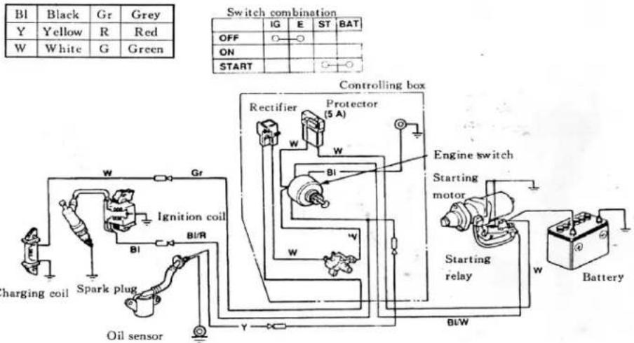
ELECTRIC DIAGRAM
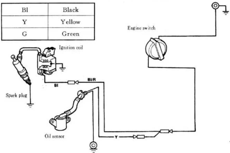

Please Read this Owner's Manual Carefully before Operating Your New Pressure Washer.
This Owner's Manual includes the operation and maintenance of the PRESSURE STORM SERIES
LFQ2130 (CA), LFQ2565 (CA), LFQ2565E (CA) LFQ2865 (CA) LFQ3370 (CA), LFQ3370E (CA)
Thank you for purchasing our Pressure Storm Pressure Washer!
All information in this publication is based on the latest product information available at the time of approval for printing. We reserve the right to make changes at any time without notice and without incurring any obligation. The copyright of this manual belongs to EquipSource, LLC. No parts of this publication may be reproduced without the written permission of EquipSource, LLC. This manual should be considered a permanent part of the generator and should remain with it if is resold.
For Product Support and Service Please Visit Us at www.lifanpowerusa.com Or Call Toll Free 1-866-471-7464
LIFAN POWER USA
LIFAN Power USA is proud to offer it's extensive line of LIFAN Power Equipment!!!! LIFAN Power USA is the sole distribution for LIFAN Power Equipment in the United States. LIFAN's unmatched investment in research and development ensures quality engines, generators, pressure washers, and water pumps at an extraordinary value. LIFAN continues to be an innovator and presently holds over 3,000 patents. Product performance has earned LIFAN the reputation of dependability and value in all their international markets.
LIFAN has been manufacturing and selling innovative and value driven products worldwide for over 15 years. LIFAN is distributed in over 100 countries. LIFAN is the largest privately owned company in China with sales over One-Billion Dollars annually and 14,000 employees. As the largest engine manufacturer in China, LIFAN builds more than five million small engines each year. This worldwide presence has been made possible by producing equipment that is durable, reliable, and rugged for any market.
LIFAN Power USA prides itself in standing behind all LIFAN products with our comprehensive warranty policy. LIFAN Power USA continues to offer the highest level or service and support in the industry. With proven performance and unmatched value, LIFAN Power Equipment will always keep you running.
All information in this publication is based on the latest product information available at the time of approval for printing. EquipSource, LLC reserves the right to make changes at any time without notice and without incurring any obligation. The copyright of this document belongs to EquipSource, LLC. No parts of this publication may be reproduced without the written permission of EquipSource, LLC.
For additional product information of any LIFAN Power Equipment, please visit us at our website - www.lifanpowerusa.com.
LIFAN POWER USA 2205 Industrial Park Rd. Van Buren, AR 72956 www.lifanpowerusa.com 866-471-7464