
NC2443ML - Video projector NEC - Free user manual and instructions
Find the device manual for free NC2443ML NEC in PDF.


| Product Type | DLP Cinema® Projector for professional use |
| Model | NEC NC2443ML |
| Projection Method | 3-chip DLP Cinema |
| Panel Resolution | 4096 x 2160 (4K) |
| Light Source | Laser diode, approx. 30,000 hours life |
| Screen Size (Max) | Up to 22 m (dependent on light module) |
| Contrast Ratio | 2000:1 (DCI specified color) |
| Lens Adjustment | Motorized shift (V/H), zoom, focus, douser |
| Dimensions (W x D x H) | 697 mm x 1095 mm x 509.5 mm |
| Net Weight (without lens) | 153 kg (with NP-24LU03/NP-20LU03), 144 kg (with NP-18LU03) |
| Power Supply (C1 Connection) | AC 200-240V single-phase 50/60Hz |
| Power Supply (C2 Connection) | Projector: AC 100-240V; Light: AC 200-240V single-phase 50/60Hz |
| Power Consumption (C1) | 3182 W / 3146 W |
| Power Consumption (C2) | Projector: 362 W / 352 W; Light: 2820 W / 2794 W |
| Noise Level | 50 dB or less |
| Operating Temperature | 10°C to 35°C |
| Operating Humidity | 10% to 85% (non-condensing) |
| Installation Orientation | Desk front/rear, ceiling front/rear |
| Laser Safety Class | Class 1 (IEC 60825-1), RG3 (IEC/EN 62471-5) |
| Key Features | Lens memory, light memory, auto brightness/color adjustment, 8 preset buttons, network control via DCC, metal filters, sealed optical system |
| Cleaning | Cabinet: dry cloth; Lens: blower/paper; Air filters: metal, reusable, clean regularly |
| User Serviceable Parts | None. Installation and maintenance by authorized technicians only |
Frequently Asked Questions - NC2443ML NEC
User questions about NC2443ML NEC
0 question about this device. Answer the ones you know or ask your own.
Ask a new question about this device
Download the instructions for your Video projector in PDF format for free! Find your manual NC2443ML - NEC and take your electronic device back in hand. On this page are published all the documents necessary for the use of your device. NC2443ML by NEC.
USER MANUAL NC2443ML NEC
DLP Cinema® Projector Head
NP-42HD
Light Module
NP-24LU03/NP-20LU03/NP-18LU03
DLP Cinema® Projector
NP-NC2443ML/NP-NC2043ML/ NP-NC1843ML
Sharp NEC Display Solutions, Ltd.
Precautions: Please read this manual carefully before using your NP-42HD/NP-NC2443ML/NP-NC2043ML/NP-NC1843ML and keep the manual handy for future reference. The NP-42HD (projector head) is called the "projector" in this manual.
- DLP (Digital Light Processing), DLP Cinema and DLP Cinema logo are trademarks of Texas Instruments.
- Microsoft, Windows and Internet Explorer are either registered trademarks or trademarks of Microsoft Corporation in the United States and/or other countries.
- Mozilla and Firefox are either registered trademarks or trademarks of the Mozilla Foundation in the United States and/or other countries.
- Oracle and Java are registered trademarks of Oracle and/or its affiliates.
- Linux is a registered trademark of Linus Torvalds in the United States and/or other countries.
- Other product names and logos mentioned in the user's manual may be the trademarks or registered trademarks of their respective holders.
- The display screens and illustrations shown in this manual may differ slightly from the actual ones.
• GPL/LGPL Software Licenses
• The product includes software licensed under GNU - General Public License (GPL), GNU Lesser General Public License (LGPL), and others.
- For more information on each software, see "readme.pdf" inside the "about GPL&LGPL" folder on the supplied CD-ROM.

WARNING
TO REDUCE THE RISK OF FIRE OR ELECTRIC SHOCK, DO NOT EXPOSE THIS APPLIANCE TO RAIN OR MOISTURE.

CAUTION
TO PREVENT ELECTRIC SHOCK, DO NOT OPEN TOP COVER. NO USER SERVICEABLE PARTS INSIDE.

This symbol warns the user that uninsulated voltage within the unit may have sufficient magnitude to cause electric shock. Therefore, it is dangerous to make any kind of contact with any part inside of this unit.

This symbol alerts the user that important literature concerning the operation and maintenance of this unit has been included. Therefore, it should be read carefully in order to avoid any problems.
Laser Safety Caution
This product is classified as Class 1 of IEC 60825-1 Third edition 2014. This product is classified as RG3 of IEC/EN 62471-5 First edition 2015.
Obey the laws and regulations of your country in relation to the installation and management of the device.

CAUTION
Use of controls or adjustments of procedures other than those specified herein may lead to hazardous laser radiation exposure.
- No direct exposure to the beam shall be permitted, RG3 IEC/EN 62471-5:2015.
- Operators shall control access to the beam within the hazard distance or install the product at the height that will prevent spectators' eyes from being in the hazard distance.
- Do not look at operating light source. Eye injury may result.
• Not for household use. (for USA) - This projector must be installed high enough to provide clearance for people who may walk beneath the beam path or hazard distance. (for USA)
- Direct exposure of human eyes to beam is prohibited.
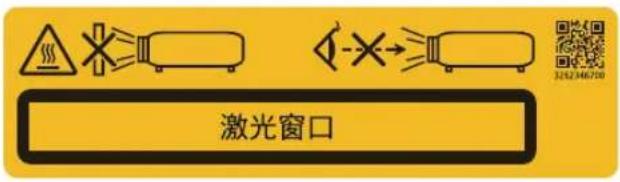
- The following graphic symbol indicating that looking into the projector is prohibited is displayed on the projector cabinet.

- Do not allow to look into the projector beam at any distance from the projector. An adult should supervise the children to prevent exposure risks.
- Check that there is no one looking at the lens, when using the remote control for starting the projector.
- Do not look at the projected light using optical devices (binoculars, telescopes, magnifying glasses, reflectors, etc). Doing so could result in vision impairment.
- When performing the lens shift adjustment, make sure that you are behind or beside the projector. Doing so from the front of the projector may cause intense light to enter into your eyes, resulting in damage to them.
- [WARNING: MOUNT ABOVE THE HEADS OF CHILDREN.] The use of a ceiling mount is recommended with this product to place it above the eyes of children.
- This projector, which is an RG3 product, is for business use and must be installed in location where safety is assured. For this reason, installation of the projector and mounting and removal of the lens unit must be performed by professional service personnel. To do the works, be sure to consult your dealer. NEVER install the projector by end users. Doing so may cause visual impairment and other injuries.
- Keep any items such as magnifying glass out of the light path of the projector. The light being projected from the lens is extensive, therefore any kind of abnormal objects that can redirect light coming out of the lens, can cause unpredictable outcome such as fire or injury to the eyes.
- When turning on the projector, ensure that nobody is facing towards the lens in the path of the light emitted from the laser.
- This product can only be operated in theaters by specified personnel. Customers should not operate this product.
Machine Noise Information Regulation - 3. GPSGV,
The highest sound pressure level is less than 70 dB (A) in accordance with EN ISO 7779.

WARNING
This equipment is compliant with Class A of CISPR 32. In a residential environment this equipment may cause radio interference.
FCC Information (for USA only)

WARNING
- The Federal Communications Commission does not allow any modifications or changes to the unit EXCEPT those specified by Sharp NEC Display Solutions of America, Inc. in this manual. Failure to comply with this government regulation could void your right to operate this equipment.
- This equipment has been tested and found to comply with the limits for a class A digital device, pursuant to Part 15 of the FCC Rules. These limits are designed to provide reasonable protection against harmful interference when the equipment is operated in a commercial environment. This equipment generates, uses, and can radiate radio frequency energy and, if not installed and used in accordance with the instruction manual, may cause harmful interference to radio communications. Operation of this equipment in a residential area is likely to cause harmful interference in which case the user will be required to correct the interference at his own expense.
Supplier's declaration of conformity (for USA only)
This device complies with Part 15 of the FCC Rules. Operation is subject to the following two conditions.
(1) This device may not cause harmful interference, and (2) this device must accept any interference received, including interference that may cause undesired operation.

U.S. Responsible Sharp NEC Display Solutions of
Party: America, Inc.
Address: 3250 Lacey Rd, Ste 500
Downers Grove, IL 60515
Telephone Number: 630-467-3000
Type of Product: Projector
Equipment Class A Peripheral
Classification:
Model Number: NP-42HD/NP-NC2443ML/
NP-NC2043ML/NP-NC1843ML

WARNING
THE END USER IS NOT ALLOWED TO OPEN OR MODIFY THE PRODUCT.
NO USER SERVICEABLE PARTS.
MAINTAIN AND SERVICE OF THE PRODUCT IS ONLY TO BE HANDLED BY NEC AUTHORIZED TECHNICIANS.
Important Safeguards
These safety instructions are to ensure the long life of your projector and to prevent fire and shock. Please read them carefully and heed all warnings.
Installation
-
Do not point the projection beam toward other people or reflective objects.
-
Consult your dealer for information about transporting and installing the projector. Do not attempt to transport and install the projector yourself.
The projector must be installed by qualified technicians in order to ensure proper operation and reduce the risk of bodily injury.
- Place the projector on a flat, level surface in a dry area away from dust and moisture. Tilting the front of the projector up or down from level could reduce laser life.
Do not put the projector on its side when the laser is on.
Doing so may cause damage to the projector.
-
Do not place the projector in direct sunlight, near heaters or heat radiating appliances.
-
Exposure to direct sunlight, smoke or steam could harm internal components.
-
Handle your projector carefully. Dropping or jarring your projector could damage internal components.
-
When moving the projector, be sure to remove the lens from the projector before moving it.
-
To carry the projector, a minimum of six persons are required.
-
Do not hold the lens part with your hand. Otherwise the projector may tumble or drop, causing personal injury.
-
Do not place heavy objects on top of the projector.
-
Turn off the projector, and disconnect the power cable before moving the projector.
For C2 connection, turn off the projector, shut down the AC power to the projector and the light using a circuitbreaker.
Disconnect the cables between devices and the light before moving the projector.
-
The cooling fan settings need to be configured when using the projector in a location at an altitude of approximately 5500 feet/1600 meters or higher. Consult your dealer in advance.
-
Turn off the projector when removing and installing lenses. Failure to do so can cause loss of vision.
For mounting or replacing the lens, please contact your dealer.
- Do not install and store the projector in the below circumstances.
Failure to do so may cause of malfunction.
• In powerful magnetic fields
• In corrosive gas environment
- Outdoors
-
If you wish to have the projector installed on the ceiling;
-
Do not attempt to install the projector yourself.
- The projector must be installed by qualified technicians in order to ensure proper operation and reduce the risk of bodily injury.
- In addition, the ceiling must be strong enough to support the projector and the installation must be in accordance with any local building codes.
-
Please consult your dealer for more information.
-
When moving the projector, check the following:
-
That the projector is turned off, the power plug is disconnected from the outlet
- That the connector cable that connects the device to the projector is unplugged

WARNING
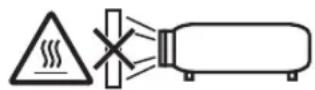
- Do not cover the lens with the supplied lens cap or equivalent while the projector is on. Doing so can lead to distorting or melting of the cap and burning your hands due to the heat emitted from the light output.
- Do not place any objects, which are easily affected by heat, in front of the projector lens. Doing so could lead to the object melting from the heat that is emitted from the light output.
The following graphic symbol is shown on the projector cabinet.
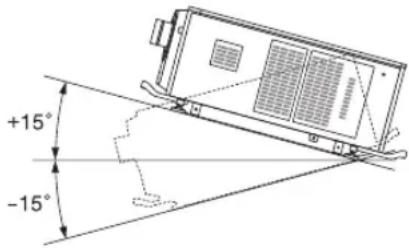
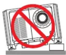
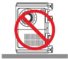
When using the projector tilted in the forward or backward direction, use it in the range of (+15^ to -15^) from horizontal. If you tilt it outside of this range or tilt it to the left or right, it may become damaged.
If the projector is tilted outside of this range when used tilted in the forward or backward direction, "TiltDegreeOver" is displayed on the LCD screen. If this message appears, change the installation of the projector so that the angle is within the given range from horizontal.
When installed on a floor or a desktop

CAUTION
This equipment is not suitable for use in locations where children are likely to be present
Power Supply
- Consult your dealer for installing the power cable to the projector. DO NOT install the power cable by yourself.
Doing so may cause a fire or electric shock.
The projector is so designed that it operates with the power supply voltage described below.
For C1 connection
(When the AC power to the projector power supply and the light power supply is provided by a single cable)
• AC 200V-240V single phase 50/60Hz
For C2 connection
(When the AC power to the projector power supply and the light power supply is provided by separate cables)
- AC 100V-240V single phase 50/60Hz (projector power supply)
- AC 200V-240V single phase 50/60Hz (light power supply)
Ensure that your power supply fits this requirement before attempting to use your projector.
- The power cable is not included with the projector. Ask your dealer for the power cable to select and purchase. Use a power cable that meets the standards and power supply voltage of the country where you are using the projector.
Refer to "2-2. Connecting the Power Cable" (page 26) for details on connecting the power cable.
-
Handle the power cable carefully. A damaged or frayed power cable can cause electric shock or fire.
-
Do not bend or tug the power cable excessively.
- Do not place the power cable under the projector, or any heavy object.
- Do not cover the power cable with other soft materials such as rugs.
- Do not heat the power cable.
-
Do not change the arrangement of the installed power cable.
-
If the projector will not be used for an extended period of time, turn off the projector, and disconnect the power plug from the outlet.
- Placing the power cable and the signal cable closely to each other can cause beat noise. If this happens, keep the two separated so that beat noise is not generated.
Beat noise is corruption of the picture often seen as a rolling band moving through the image. - Do not touch the projector during a thunder storm. Doing so can cause electrical shock or fire.
- When installed on the ceiling, install the breaker in a location that is easy to reach by hand.
Fire and Shock Precautions
- Ensure that there is sufficient ventilation and that vents are unobstructed to prevent potentially dangerous concentrations of ozone and the build-up of heat inside your projector. Allow at least 24 inches (60 cm) of space between your projector and a wall. In particular, clear a space of 26.7 inches (70 cm) or more in front of the air outlet on the rear surface and 12 inches (30 cm) or more on the upper part of the projector body.
- Prevent foreign objects such as paper clips and bits of paper from falling into your projector. Do not attempt to retrieve any objects that might fall into your projector. Do not insert any metal objects such as a wire or screw-driver into your projector. If something should fall into your projector, shut down the AC power to the projector immediately and have the object removed by a qualified service person.
For C2 connection, turn off the projector, shut down the AC power to the projector and the light using a circuit breaker, and contact your dealer/distributor.
-
Turn off the projector, shut down AC power by using a circuit breaker and contact qualified service personnel under the following conditions. For C2 connection, turn off the projector, shut down the AC power to the projector and the light using a circuit breaker, and contact your dealer/distributor for a repair.
-
When the power cable or plug is damaged or frayed.
-
If liquid has been spilled into the projector, or if it has been exposed to rain or water.
-
If the projector does not operate normally when you follow the instructions described in this user's manual.
- If the projector has been dropped or the cabinet has been damaged.
-
If the projector exhibits a distinct change in performance, indicating a need for service.
-
Keep any items such as magnifying glass out of the light path of the projector. The light being projected from the lens is extensive, therefore any kind of abnormal objects that can redirect light coming out of the lens, can cause unpredictable outcome such as fire or injury to the eyes.
- Never remove or open the projector cabinet and never modify the projector. Otherwise, fire, electric shock, or leakage of laser light may cause visual impairment or burn injuries.
- When using a LAN cable:
For safety, do not connect to the connector for peripheral device wiring that might have excessive Voltage.
- Do not try to touch the air outlets on the projector during normal projector operation as it is hot.
Cleaning
- Shut down AC power by using a circuit breaker before cleaning.
For C2 connection, turn off the projector, shut down the AC power to the projector and the light using a circuit breaker.
- Clean the cabinet periodically with a cloth. If heavily soiled, use a mild detergent. Never use strong detergents or solvents such as alcohol or thinner.
- Use a blower or lens paper to clean the lens, and be careful not to scratch or mar the lens.
- Do not handle the projector and the power cable with wet hands. Doing so can cause electrical shock or fire.

CAUTION
- Do not shut down AC power to the projector under the following conditions. Doing so can damage the projector.
• While projecting images
- While cooling after the power is turned off. (The STATUS indicator LED blinks in orange while the fan is rotating, and “cooling...” is displayed on the LCD screen.)
- When using the IMB: 180 seconds
- During IMB Operation (if the projector standby state)
- Do not turn of the AC power for 90 seconds after the Laser is turned on and while the POWER indicator is blinking green. Doing so could cause premature Laser failure.
- Keep hands away from the lens mounting portion while the lens shift is in operation. Failure to do so could result in fingers being pinched between the cabinet and lens cover.
- When main body is damaged, cooling fluids may come out of internal part.
Should this happen, immediately turn off the AC supply to the projector and contact your dealer.
DO NOT touch and drink the cooling fluid.
When the cooling fluids are swallowed or contacted with your eyes, please consult with doctors immediately.
Caution on Carrying the Projector/Handling the Optional Lens
The projector should always be carried by at least 6 people, holding the handles on the front and back of the main body and the grips on the bottom. Remove the lens unit from the projector body when moving the projector.
When installing / removing a lens, shut down the AC power to the projector.
When shipping the projector with the lens, remove the lens before shipping the projector. Always attach the dust cap to the lens whenever it is not mounted on the projector. The lens and the lens shift mechanism may encounter damage caused by improper handling during transportation.
Light Module
- A light module containing multiple laser diodes is included in the product as the light source.
- These laser diodes are sealed in the light module. No maintenance or service is required for the performance of the light module.
- End user is not allowed to replace the light module.
- Contact qualified distributor for light module replacement and further information.
Cable information
Use shielded cables or cables attached ferrite cores so as not to interfere with radio and television reception.
For details, please refer to "2. Installation and Connection" in this user's manual.
Installing the Projector
This projector is an RG3 product. The projector is for professional use and must be installed in location where safety is assured. For this reason, be sure to consult your dealer as installation and attachment/detachment of the lens unit must be performed by a professional service personnel.
Never try to install the projector by yourself. This may result in visual impairment etc.
Connecting the power cord to earth
This equipment is designed to be used in the condition of the power cord connected to earth. If the power cord is not connected to the earth, it may cause electric shock. Please make sure the power cord is earthed properly.
Do not use a 2-core plug converter adapter.
is not in Handling the power cord
- When connecting the power cord to the projector's AC IN terminal, make sure the connector is fully and firmly inserted. Be sure to fix the power cord using the power cord stopper. Loose connection of the power cord could lead to fire or electric shock.
- Do not connect or disconnect the power cord with wet hands. Doing so could result in electric shock.
Lens shift, focus and zoom operations
- When shifting the lens or adjusting the focus or zoom, do so from either behind or to the side of the projector. If adjustments are performed from the front, your eyes could be exposed to strong light and get injured.
- Keep your hands away from the lens area when performing the lens shift operation. If not, your fingers could get caught in the gap between the cabinet and the lens.
Disposing of your used product

EU-wide legislation as implemented in each Member State requires that used electrical and electronic products carrying the mark (left) must be disposed of separately from normal household waste.
This includes projectors and their electrical accessories. When you dispose of such products, please follow the guidance of your local authority and/or ask the shop where you purchased the product.
After collecting the used products, they are reused and recycled in a proper way. This effort will help us reduce the wastes as well as the negative impact to the human health and the environment at the minimum level.
The mark on the electrical and electronic products only applies to the current European Union Member States.
Outside the European Union
If you wish to dispose of used electrical and electronic products outside the European union, please contact your local authority and ask for the correct method of disposal.

For EU: The crossed-out wheeled bin implies that used batteries should not be put to the general household waste! There is a separate collection system for used batteries, to allow proper treatment and recycling in accordance with legislation.
According to the EU directive 2006/66/EC, the battery can't be disposed improperly. The battery shall be separated to collect by local service.
For questions relating to unclear points or repairs
Contact your dealer or the following support branch for questions relating to unclear points, malfunctions and repairs of the product.
In Europe
Company Name: Sharp NEC Display Solutions Europe GmbH
Address: Landshuter Allee 12-14, D-80637 Munich, Germany
Telephone: +49 89 99699 0
Fax Line: +49 89 99699 500
Email Address: infomail@nec-displays.com
WEB Address: https://www.sharpnecdisplays.eu
In North America
Company Name: Sharp NEC Display Solutions of America, Inc.
Address: 3250 Lacey Rd, Ste 500
Downers Grove, IL 60515 U.S.A.
Telephone: +1 866-632-6431
Email: cinema.support@sharpnec-displays.com
WEB Address: https://www.sharpnecdisplays.us
In China
Company Name: NEC (China) Co., Ltd.
Address: 6F, Landmark diplomatic office building D2,
No. 19 East Road, Chaoyang District,
Beijing 100600, R.P.C.
Telephone: 010-59342706
Email Address: nec-support@nec.cn
In Hong Kong and Taiwan
Company Name: Strong Westrex, Inc.
Address: Room 4108 China Resources Building, No. 26 Harbour Road, Wanchai, Hong Kong
Telephone: +852 2827 8289
Fax Line: +852 2827 5993
Email Address: Felix.chen@btn-inc.com
In South Korea
Company Name: Hyosung ITX Co., Ltd.
Address: 1F, Ire Building, 2, Yangpyeong-dong 4-ga, Yeongdeungpo-gu, Seoul, Korea 150-967
Telephone: +82-2-2102-8591
Fax Line: +82-2-2102-8600
Email Address: moneybear@hyosung.com
WEB Address: http://www.hyosungitx.com
In Australia and New Zealand
Company Name: NEC Australia Pty Ltd
Address: 26 Rodborough Road Frenchs Forest NSW 2086
Telephone: 131 632 (from anywhere in Australia)
Email Address: displays@nec.com.au
WEB Address: http://www.nec.com.au
In Thailand, Singapore, Malaysia, Indonesia and Philippines
Company Name: Goldenduck International Co., Ltd.
Address: 65 Soi Phutthamothon Sai 1, 21 Bangramad, Talingchan, Bangkok, Thailand 10170
Telephone: +66-2887-8807
Fax Line: +66-2887-8808
Email Address: contact@goldenduckgroup.com
Label Information
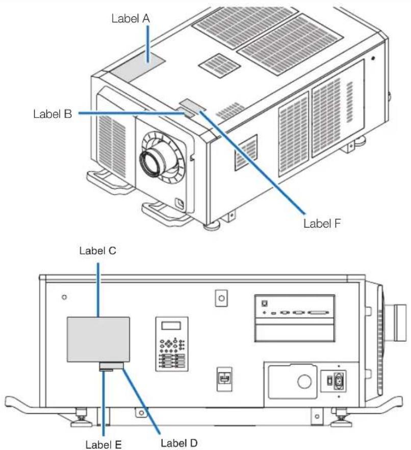
About the laser module used in the light source
- This product has a built-in laser module. Control and adjustment procedures other than those described in this document may result in exposure to hazardous laser radiation.
- This product is classified as a Class 1 of Laser Product Safety Standard JIS C 6802: 2014, IEC 60825-1 3rd Edition: 2014. This product is classified as Risk Group 3 of IEC/EN 62471-5 1st Edition: 2015.
- This product complies with performance standards for laser products under 21 CFR Part 1040 except with respect to those characteristics authorized by Variance Number 2015-V-3435 effective on April 7, 2016.
Outline of laser emitted from the built-in light module:
Wave length: Red 635–647 nm, Blue 450–470 nm
Maximum power: Red 86 W, Blue 1,044 W
Radiation pattern from the lens (the protective housing):
Wave length: Red 635–647 nm, Blue 450–470 nm
Maximum laser radiation output: Red 500 mW, Blue 900 mW
The explanatory label of the laser product is put on the top of the projector.
CLASS 1 LASER PRODUCT

WARNING RG3 PRODUCT
• No direct exposure to the beam shall be permitted.
- Do not look into the projector's lens. Serious damage to your eyes could result.
• Not for household use.
- Operators shall control access to the beam within the hazard distance and install the product at the height that will prevent exposures of spectators' eyes within the hazard distance.
- This projector must be installed high enough to provide clearance for people who may walk beneath the beam path or hazard distance. (FDA)
Label A
Lamp Warning/Laser Explanatory Label
RISK GROUP 3
WARNING
DO NOT LOOK INTO THE BEAM.
NO DIRECT EYE EXPOSURE TO THE BEAM IS PERMITTED.
HAZARD DISTANCE: REFER TO THE MANUAL
NO DIRECT EXPOSURE TO BEAM SHALL BE PERMITTED
NOT FOR HOUSEHOLD USE
GROUPE DE RISQUE 3
MISE EN GARDE
NE PAS REGARDER DIRECTEMENT DANS LE FAISCEAU
L'EXPOSITION DIRECTE DES YEUX AU FAISCEAU EST INTERDITE.
DISTANCE À RISQUE: SE REPORTER AU MANUEL.
L'EXPOSITION DIRECTE AU RAYON DOIT ÊTRE AUTORISÉE.
NE CONVIENT PAS A UN USAGE DOMESTIQUE.
RISIKOGRUPPE 3
WARNUNG
CLASS 1 LASER PRODUCT
LASERPRODUKT DER KLASSE 1
APPAREIL À LASER DE CLASSE 1
Warning/Aperture Label
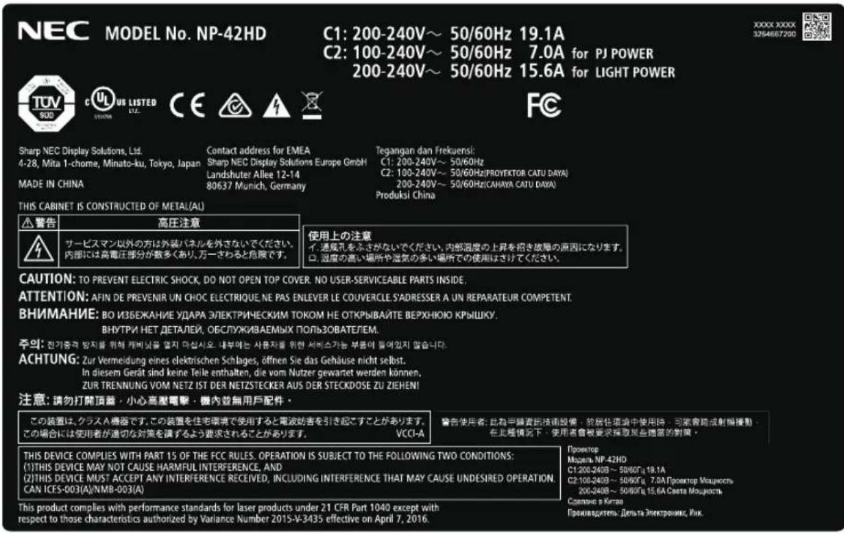
Label C (NP-42HD)
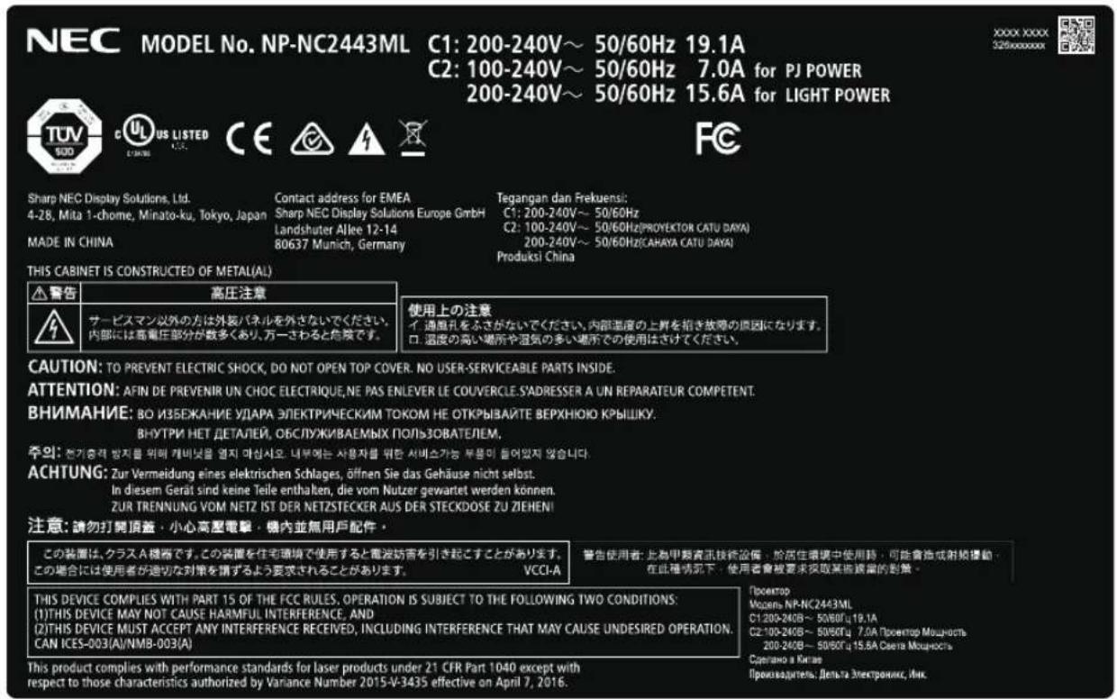
Label C (NP-NC2443ML)
Label C (NP-NC2043ML)
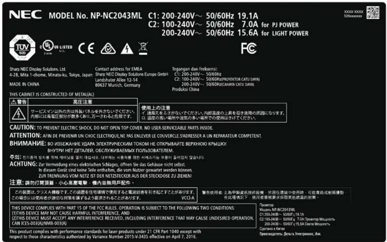
Label C (NP-NC1843ML)
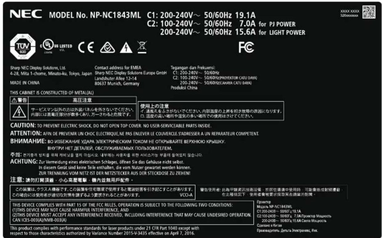
Label E
M/F Date : YYYY.MM.DD
Label F
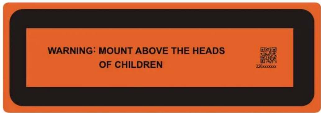
Laser radiation range/No entry range (HD: Hazard distance)
- The below table describes the radiation range of emitted light by the projector that is classified as Risk Group 3 (RG3) in the IEC 62471-5 First edition 2015.
- Please keep within bounds for installing the projector.
Install a barrier for preventing human eyes from entering the RG3 area. For the barrier installation position, keep horizontal safety zone over 1m from the RG3 area. In case to install the projector over head, keep over 2m (2.5m for USA) distance at least between the floor surface and the RG3 area.
Operators shall control access to the beam within the hazard distance or install the product at the height that will prevent exposures of spectators' eyes within the hazard distance.
NP-42HD/NP-NC2443ML/NP-NC2043ML/NP-NC1843ML
(IEC 62471-5 First edition 2015)
| Lens RG3 HD(m) | Screen size(m) | |||
| H | V | |||
| NC-60LS12ZW | Wide | 1.5 1.27 | 0.67 | |
| Tele | 2.2 1.27 | 0.67 | ||
| NC-60LS12Z | Wide | 1.2 1.08 | 0.57 | |
| Tele | 2.2 1.26 | 0.66 | ||
| NC-60LS14Z | Wide | 1.7 1.26 | 0.67 | |
| Tele | 2.6 1.28 | 0.68 | ||
| NC-60LS16Z | Wide | 1.9 1.21 | 0.64 | |
| Tele | 3.3 1.35 | 0.71 | ||
| NC-60LS19Z | Wide | 2.3 1.17 | 0.61 | |
| Tele | 4.0 1.21 | 0.64 | ||
| NC-60LS24Z | Wide | 3.0 1.20 | 0.63 | |
| Tele | 4.9 1.22 | 0.65 | ||
| NC-60LS39Z | Wide | 5.0 1.24 | 0.65 | |
| Tele 8.4 1.27 0.67 | ||||
When installed on a floor or a desktop
When installed on a ceiling
![Horizontal safety zone: over 1m H RG3 range [Plan view] Horizontal safety zone: over 1m HD V RG3 range [Side view] Vertical safety zone: over 2m (2.5m for USA) floor](/content/2026/05/1059255/images/cd1182abd4d0d262552dbaaf8392d9efe2611988f9bab9a3e5f933a5871b863f.jpg)
* If lens shift is utilized, please consider the shift of projected image according to the volume of lens shift.

CAUTION
Please heed all precaution for safety.
To install the projector
- For planning the layout of the projector, make sure to take safety measures instructed on the installation manual.
- In order to refuse danger, install either a wall outlet within easy reach for pulling out the power plug in emergency or a device as a breaker to shut down the power supply to the projector.
• Take safety measures preventing human eyes from entering the RG3 area. - Considering the installation place, select an appropriate lens and secure safety zone that is determined for each lens. For operation on the powered projector as light adjustment, make sure appropriate safety measures have been taken.
- Check the validity of taken security measures if appropriate safety zone based on the installed lens is secured. Periodically check the validity and keep these results.
• Educate the administrator of the projector (operators) about safety before starting to operate the projector. - This projector is an RG3 product. The projector is for professional use and must be installed in location where safety is assured. For this reason, be sure to consult your dealer as installation and attachment/detachment of the lens unit must be performed by a professional service personnel. Never try to install the projector by yourself. This may result in visual impairment etc.
To use the projector
- Instruct the administrator of the projector (operators) to perform inspections before powering on the projector. (Including the safety check against emitted light by the projector)
- Instruct the administrator of the projector (operators) to be in circumstances able to control the projector whenever the projector is powered on for an emergency.
- Instruct the administrator of the projector (operators) to keep the installation manual, user's manual and inspection records to a place where they can take these documents out easily.
- Instruct them to clarify if the projector is conformed to standards of each country and region.
Important Information 2
1. What's in the Box? and the Names of the Projector Parts......16
1-1. Features....16
1-2. What's in the Box?....18
1-3. Names of the Projector Parts....19
2. Installation and Connection....25
2-1. Steps for setting up and connecting....25
2-2. Connecting the Power Cable ....26
2-3. Connecting the image input terminals....31
2-4. Connecting the various control terminal ....31
3. Projection of Images (Basic Operation)....32
3-1. Steps of projecting images....32
3-2. Turning your projector on 33
3-3. Selecting the title of input signal....35
3-4. Adjusting the position and the size of projected screen....36
3-5. Preventing misoperations....40
3-6. Turning on/off the light with the projector turned on....41
3-7. Turning your projector off 42
4. Using Menus 44
4-1. Basic operation with adjustment menus ....44
4-2. Table of adjustment menus ....49
4-3. Title Select....51
4-4. Configuration....52
4-5. Title Setup ....54
4-6. Information....54
5. Maintenance of Your Projector 58
5-1. Cleaning the Cabinet ....58
5-2. Cleaning the Lens ....59
5-3. Cleaning the Air Filters....59
6. Appendix 62
6-1. Troubleshooting 62
6-2. Indicator display list....63
6-3. Operation using an HTTP browser....66
6-4. Writing of the log file (Save Information)....68
6-5. Outline Drawing....71
6-6. Specifications....72
6-7. Pin Assignment and Functions of Terminal 73
6-8. Related products list....80
1.
What's in the Box? and the Names of the Projector Parts
1-1. Features
- DLP Cinema® projector
Complies with the strict projection standards defined by the Digital Cinema Initiatives (DCI) industry group in the United States using leading imaging technology of NEC. It also supports 3D projection and high frame rates (HFR).
• Employs a long life laser light source
The projector employs a newly developed laser light source offering excellent reliability and redundancy. Since the laser light source has a long life (approx. 30,000 hours), this delivers low cost operation by removing the need for maintenance such as replacing and adjusting the light module over extended periods of time. Furthermore, it reduces the risk of the light source suddenly shutting off and leaving a black screen.
- Delivers reduced installation space and increased freedom through a more compact and lightweight body
The use of a 0.98" DC4K chip achieves 4K high resolution. In addition, the integration of the light module into the projector main unit offers smaller footprint as well as improving the degree of freedom of installation, such as removing the need to connect the projector to an external exhaust duct and supporting both floor-mounted and ceiling-suspended installation. A wide variety of optional lenses (sold separately) are also available for the projector in order to support a wide variety of installation methods (a lens is not mounted when the projector is shipped from the factory).
• Equipped with easy to use functions
(1) Lens memory function and light memory function that can be operated with one touch.
The projector is equipped with a lens memory function that can save the zoom position and shift position of the lens and a light memory function that can save the brightness setting separately for each input signal. This makes it possible to project using preconfigured settings simply by selecting the signal when projecting multiple different input signals each with different screen size and brightness settings (Refer to "6-8. Related products list" (page 80) for details on the lenses that support the lens memory function).
(2) Built-in automatic adjustment function that makes the brightness and color of the light source uniform
Degradation of brightness and variations in color that occur as the light source is used for longer periods of time are kept to a minimum (the period over which variations in brightness can be limited varies depending on the brightness setting).
(3) Frequently used titles can be registered in preset buttons
The projector has been equipped with 8 preset buttons that make it easy to select registered title (input signal). To this projector, 100 titles at most can be registered (input signal registration). Among the registered titles, any 16 titles can be assigned to the preset buttons.
(4) You can operate and configure the projector via a network from a PC
You can operate and configure the projector via a network from a PC by using the separately supplied software Digital Cinema Communicator (DCC) v2.
• Excellent dust-proof performance
A circulating cooling system is used to cool the optical components. The system converts warm air into cold air and circulates it inside a sealed structure, so external air does not come into contact with the optical components. This prevents dust and dirt from getting on the optical components, maintaining brightness.
* Note that dust and dirt cannot be completely shut out.
- Reduced running cost thanks to the use of metal filters
The filters are made of metal, so they can be used repeatedly and do not have to be replaced when performing periodic cleaning. This not only reduces running costs, but also contributes to preserving the environment since no spent filters are discarded.
1-2. What's in the Box?
Check the content of the accessories.
1-2-1. Projector
□ Projector
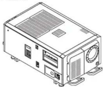
natural_image
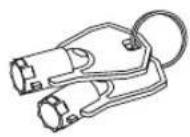
Line drawing of a computer or electronic device casing with ventilation grilles and ports (no text or symbols)□ Keys for administrator x 2
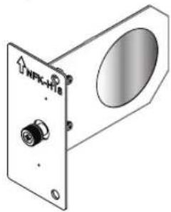
□ NFK-H18 *1
natural_image
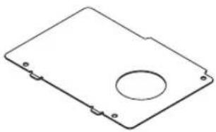
Isometric line drawing of a rectangular electronic device with a circular hole and mounting holes (no text or symbols)□ M5 × L20 light module fixing screws × 2 *2
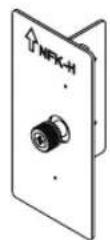
□ Power cable stopper
natural_image
Technical illustration of a mechanical device with labeled ports (NPK-H18) and a circular aperture, no readable text or symbols beyond the label.
□ Guide rail × 2
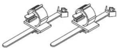
natural_image
Two identical mechanical clamping or mounting bracket designs, shown in isometric view with no text or symbols.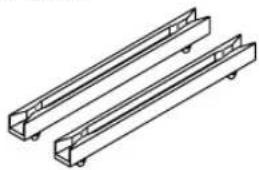
natural_image
Technical line drawing of two rectangular metal frameworks or structural beams (no text or symbols)□ CD-ROM (User's Manual)

□ Important Information
natural_image
Simple 3D illustration of a rectangular block with no text or symbols*1 NFK-H24 is packaged with NP-NC1843ML.
^*2 NP-42HD only.

In the event that you did not receive all of the accessories outlined above, or some are damaged, contact your dealer/distributor.
Differs slightly from the drawings in this manual, but there is no problem in actual use.
1-3. Names of the Projector Parts
1-3-1. Front of the projector
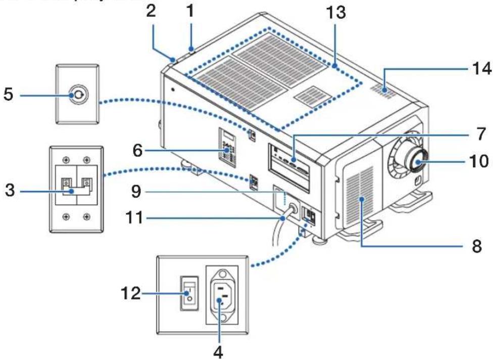
1. LIGHT status indicator
Displays the status of the light source. The indicators turn on when the light source is on and turn off when the light source is off (See page 65).
2. SYSTEM status indicator
These indicate the status of the projector. When the projector is operating normally, these light/blink in green or orange. When an error occurs, they light/blink in red. When an error occurs, check the contents of the display on the LCD screen. (See page 65)
3. Light power switch
While AC power is being supplied, set the projector power switch and light power switch to ON position, then your projector will enter a standby state.
4. AC input
Connects to the AC power cable. The AC power cable is not an accessory. Consult with your dealer/distributor about the AC power cable.
5. Switch for administrator
The projector can be operated normally by inserting the administrator key horizontally and turning it clockwise to the vertical position.
At this time, the administrator key cannot be removed. The projector will not function unless the administrator key is inserted.
6. Control panel
On the control panel, power to your projector is turned on or off, titles are selected, and various adjustments are made of projected screen. (See page 23)
7. Connection terminals
Various image signal cable are to be connected here. (See page 22)
You can expand signal input terminals by installing the optional board.
Contact your dealer/distributor for more information on separately sold optional products.
8. Air inlet
The air inlet for cooling inside the projector. Do not cover.
Air filters are provided on the air intakes to prevent dust from entering the projector.
- What's in the Box? and the Names of the Projector Parts
9. Remote interlock connector (inside the main unit's side panel)
This port is for safely using the laser in this device. It is used to externally control the laser illumination in the projector. Consult with your dealer/distributor about using this.
10. Lens (optional)
Images are projected from the lens. Request your dealer/distributor to install or replace the lens.
11. AC power cord
This cord supplies AC power to the projector. Please contact your dealer/distributor for connection of the AC power cord.
12. Projector power switch
When the light power switch and projector power switch are turned on with AC power supplied, the projector is set to the standby mode.
13. Air intake
These are air intake ports for introducing external air to reduce the temperature inside the projector. Do not block the port. Air filters are provided on the air intakes to prevent dust from entering the projector.
14. Exhaust port
The heat inside the projector is expelled from here. Do not block the port.
NOTE
Do not cover the air inlets and outlet while the projector is in operation. Insufficient ventilation leads to a rise of the internal temperature and may cause a fire or malfunction.
1-3-2. Rear of the projector
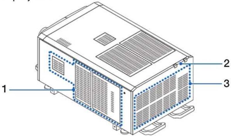
1. Air inlet
The air inlet for cooling inside the projector. Do not cover.
2. Buzzer (inside rear of projector)
A buzzer rings when an error occurs.
3. Air outlet
The air outlet to exhaust heat inside the projector. Do not cover.
NOTE
Do not cover the air inlets and outlet while the projector is in operation. Insufficient ventilation leads to a rise of the internal temperature and may cause a fire or malfunction.
1-3-3. Bottom of the projector
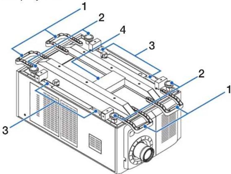
- Handle (4 locations)
Handles for moving the projector.
- Level adjusters (in 4 positions)
In the ordinary installation, you can adjust the projector inclination at 4 positions.
- Grips
These grips are used when moving the projector.
- Exhaust port
The heat inside the projector is expelled from here. Do not block the port.
1-3-4. Connection terminals
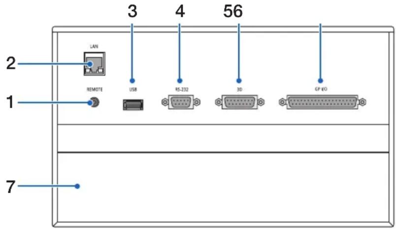
- Service terminal (REMOTE) (Stereo mini)
This terminal is used for service purpose only.
- Ethernet port (LAN) (RJ-45)
The port for interfacing with an image signal server or controlling the projector from a PC via a network. Connect the projector and the PC with a commercially available Ethernet cable (10/100/1000Base-T).
- USB port (USB) (type A)
The port for the projector maintenance.
- PC control terminal (RS-232) (D-sub 9P)
The terminal for operating the projector from a PC via an RS-232C or for service personnel to set data for the projector. Connect the projector and the PC with a commercially available RS-232C straight cable.
- 3D terminal (3D) (D-sub 15P)
The terminal for connecting a 3D image system to the projector. (See page 79)
- External control terminal (GP I/O) (D-sub 37P)
The terminal for externally controlling the projector or connecting a 3D image system to the projector. (See page 74)
- Slot
The slot is used for an image media block (IMB). Contact your dealer/distributor for an installation of IMB. Refer to the IMB instruction manual for details on IMB.
1-3-5. Control panel
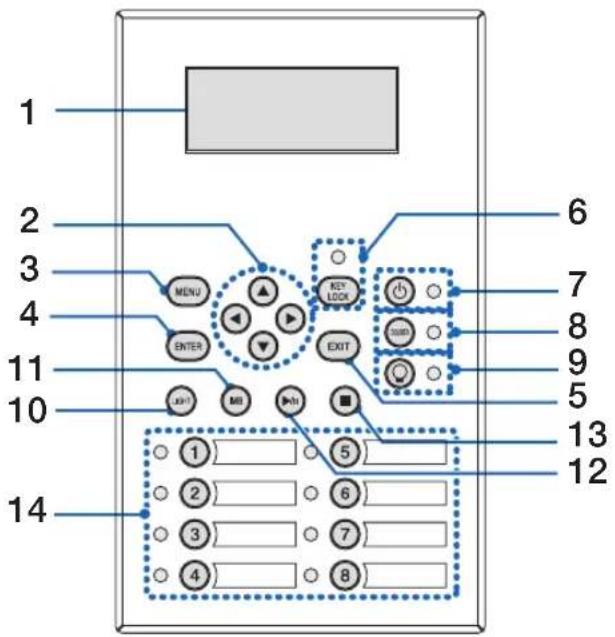
1. LCD screen
The LCD screen displays menus and setting values for the projector operations.
2. ▲/▼/◄/► (UP/DOWN/LEFT/RIGHT) buttons
Press these buttons to select a menu item while a menu is displayed.
3. MENU button
Press this button to display the menu for various settings and adjustments. (See page 49)
4. ENTER button
Press this button to select the menu item.
5. EXIT button
Press this button to return to the previous menu item.
6. KEY LOCK button
Press this button to lock (KEY LOCK) the buttons on the control panel. Buttons on the control panel do not function while KEY LOCK is on.
Pressing the KEY LOCK button for one second or longer while KEY LOCK is off locks the buttons.
Pressing the KEY LOCK button for one second or longer while KEY LOCK is on unlocks the buttons. (See page 40)
NOTE KEY LOCK becomes automatically on if no control panel operation takes place in the standby state for 30 seconds by default. (See page 40)
7. @ button (POWER button)
Press this button for more than three seconds to turn on or off (standby) the projector. (See page 64)
In order to start up the projector, turn on the main power switch for the projector to set the projector in the standby state. (See page 33)
8. DOUSER button
Press this button to open and close the douser. (See page 64)
9. button (LIGHT ON/OFF button)
Press this button for five seconds or longer to turn on or off the light source while the projector is on. (See page 41)
10. LIGHT button
Press this button to display the light source adjustment menu. (See page 39)
11. IMB button (planned to be supported in a future update)
This button is operable when the media block is installed in the projector.
Press this button to display the operation menu of the media block.
1. What's in the Box? and the Names of the Projector Parts
12. Play/pause button (planned to be supported in a future update)
This button is operable when the media block is installed in the projector. Press this button to play or pause the image contents.
13. Stop button (planned to be supported in a future update)
This button is operable when the media block is installed in the projector. Press this button to stop playing the image contents.
14. Preset buttons
Press the preset button to select a title (input signal) assigned to each button. Up to 100 titles (input signals) can be registered to this projector, and any 16 titles from them can be assigned to the preset button. Please request your dealer to register and change the titles of the buttons as required.
The preset button indicators show their assigned title or selection status. (See page 63)
TIP To select a title allocated to one of the preset buttons, use the following procedure.
- To select a title allocated to one of "Preset Button1" to "Preset Button8"
Press the button which corresponds to the number of the preset button (button <1> to <8>). - Press the <1> button to select the "Preset Button1".
- Press the <8> button to select the "Preset Button8".
• To select a title allocated to one of "Preset Button9" to "Preset Button16"
Press the preset button (button <1> to <8>) while holding down the UP button.
- Press the <1> button while holding down the UP button to select the "Preset Button9".
- Press the <8> button while holding down the UP button to select the "Preset Button16".
2. Installation and Connection
2-1. Steps for setting up and connecting
Use the following steps for setting up your projector:
- Step 1
Setup the screen and projector. (Contact your dealer to carry out the setup.)
- Step 2
Connect the power cable to the projector. (See page 26)
- Step 3
Connect cables to the image input terminals. (See page 31)
Connect cables to the various control terminals. (See page 31)
2-2. Connecting the Power Cable
Consult your dealer for installing the power cable to the projector.
If AC power is supplied to the projector and light with one power cable (C1 connection), it is not necessary to connect the cable to the projector power supply.
The power cable is not included with the projector. Use a power cable that meets the standards and power supply voltage of the country where you are using the projector. Ask your dealer for the power cable to select and purchase.

WARNING
Carefully read the contents described in this section before connection and connect the cables according to the proper procedure. Inappropriate handling may cause fatal, serious or other bodily injuries due to fire or electric shock.

WARNING
- Consult your dealer for installing the power cable to the projector.
DO NOT install the power cable by yourself. Doing so may cause a fire or electric shock. - Before connecting the power cables, check that the projector power switch and light power switch of the projector is turned off. Implement the connection with AC power shut off.
- Be sure to ground the equipment to ensure safety. Use a power cable that meets the standards and power supply voltage of the country where you are using the projector, and always connect the equipment to the ground. If the ground is not connected, it may cause electrical shocks.
- When connecting the power cable plugs to the AC IN and the electrical outlet, securely insert the plugs all the way in.
- For C2 connection, be sure to install the power cord stopper. If the connection between the power cable plug and the electrical outlet is loose, the plug area may generate heat, causing burns and accidents.

CAUTION
- This equipment is designed to be used in the condition of the power cord connected to earth. If the power cord is not connected to the earth, it may cause electric shock. Please make sure the power cord is earthed properly.
1 Connect the AC power supply cable.
Connect the AC power supply cable to the projector.
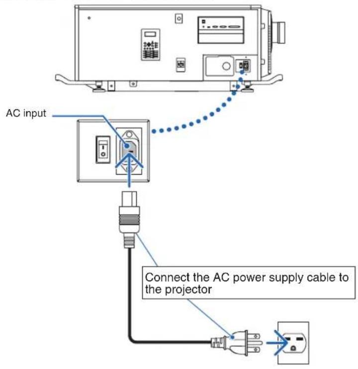
2 Connect the power plug to the electrical outlet.
This completes the connection of the AC power supply cable.
2. Installation and Connection
Attaching the power cable stopper
To prevent the power cable from accidentally removing from the AC IN of the projector, attach the supplied power cable stopper to clamp the power cable.

CAUTION
- To prevent the power cable from coming loose, make sure that all the prongs of the power cable are fully inserted into the AC IN terminal of the projector before using the power cable stopper to fix the power cable. A loose contact of the power cable may cause a fire or electric shock.
- Do not bundle the power cable. Doing this could cause heat or a fire.
NOTE
- Do not clamp the power cable with other cables. Doing so can generate noise, which can affect adversely the signal cable.
- Be careful not to insert the band inversely. Once the band is attached, it cannot be removed from the slot.
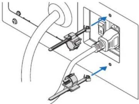
1 With the band of the clamper unit facing the power supply cord, line up the tip of the power supply cord stopper with the mounting hole in the projector body and press in.
Attach the power cord stopper on the opposite side in the same way.
natural_image
Technical diagram of a cable connector assembly with two connectors and wiring (no text or labels)2 Pass the band through the slits in the power cord stoppers.
Use the two bands to wrap the power cord from the left and right sides.
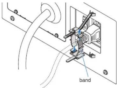
3 Slide the clamper unit to the base of the power cord.
The position of the clamper unit can be adjusted by pulling the tab in the direction of the arrow. After adjusting the position of the clamper unit, release the tab to fix the clamper unit in place.
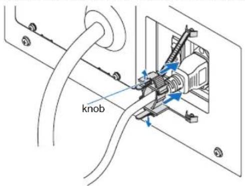
4 Pull the band to fasten the power cord.
The position of the band can be adjusted by pulling the tab in the direction of the arrow. Pull the upper and lower sections of the band in a well-balanced manner. After adjusting the position of the band, release the tab to fix the band in place.
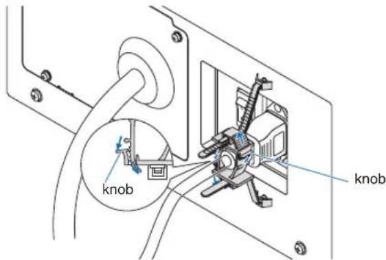
This completes the attachment of the power cable stopper.
2. Installation and Connection
Removing the power cable from the power cable stopper
Pull the knob of each clamper to remove the two bands.
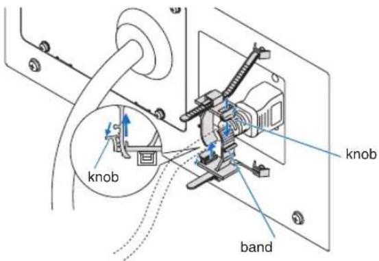

CAUTION
The projector may become hot temporarily when the power is turned off or if the AC power is disconnected while the projector is projecting. Take care when handling the projector.
2-3. Connecting the image input terminals
The video input ports that can be used with the IMB are as follows. Refer to the instruction manual of the IMB for details on connecting the video input ports with external equipment.
| IMB HDMI input port × 1 | 3G SDI input port × 2 |
2-4. Connecting the various control terminal
For control, your projector comes with such ports as the PC control terminal and the Ethernet port (RJ-45).
- PC control terminal (RS-232) ---- Use this terminal when controlling the projector in serial connection from a PC.
• LAN port (LAN)---- Use this port when controlling the projector in LAN connection from a PC.
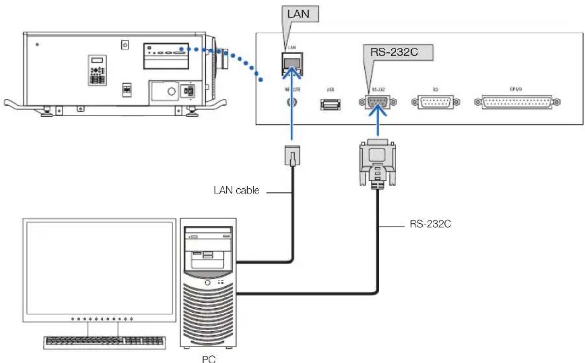
flowchart
graph TD
    A["PC"] -->|LAN cable| B["RS-232C"]
    B --> C["RS-232"]
    C --> D["3D"]
    D --> E["GP VD"]
    F["NE GTE"] -->|LAN| G["RS-232C"]
    H["USB"] --> C
    I["Computer"] --> J["PC"]
3.
Projection of Images (Basic Operation)
3-1. Steps of projecting images
- Step 1
Turn on the power to the projector. (See page 33)
- Step 2
Select the title of input signal. (See page 35)
- Step 3
Adjust the position and size of the projected screen. (See page 36)
- Step 4
Turn off the power to the projector. (See page 42)
3-2. Turning your projector on

WARNING
- The projector produces a strong light. When turning on the power, operate from the side or rear of the projector (outside the Restriction Zone (HD)). Also, when turning on the power, make sure no one within the projection range is looking at the lens.
Preparation: • Connect the power cable to the projector (see page 26).
• Supply AC power to the projector.
NOTE
- Turn off the main power switch to the projector when supplying or cutting AC power to the projector.
Supplying or shutting down the AC power while the main power switch is on will damage the projector. - Turning on and off the projector involves a two-step operation; the “main power switch” and the “POWER button”.
• Turning power on. (See this page)
[1] Turn on the "main power switch" of the projector. Your projector is set in a standby state.
[2] If KEY LOCK is on, press the KEY LOCK button for one second or longer. KEY LOCK is off and buttons on the control panel become operable.
[3] Press the POWER button three seconds or longer. Your projector is turn on.
• Turning power off. (See page 42)
[1] Press the POWER button three seconds or longer. Your projector is set in a standby state.
[2] Turn off the "main power switch" of the projector. Your projector is turned off.
1 Remove the lens cap.
2 Insert the administrator key horizontally into the administrator switch and turn it clockwise to the vertical position.
The administrator key can no longer be removed. The projector will not function unless the administrator key is inserted.
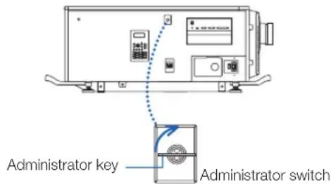
3 Turn on the power switches on the side of the projector in this order: first the light power switch (1) then the projector power switch (2).
A buzzer will ring on the projector. The POWER button indicator will blink green and the SYSTEM status indicator will light orange (standby state). KEY LOCK becomes automatically on if no control panel operation takes place in the standby state for 30 seconds by default. Buttons on the control panel do not function while KEY LOCK is on. (See page 40)
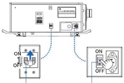
① Light power switch ② Projector power switch
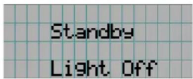
3. Projection of Images (Basic Operation)
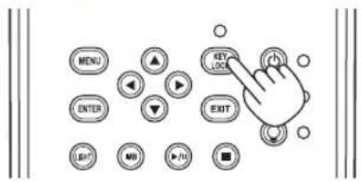
4 If KEY LOCK is on, press the KEY LOCK button for one second or longer.
KEY LOCK becomes off. The KEY LOCK button indicator turns off and buttons on the control panel become operable. (See page 40)
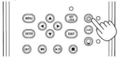
5 Press the POWER button on the control panel of your projector three seconds or longer.
Your projector is turn on.
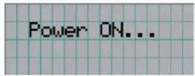
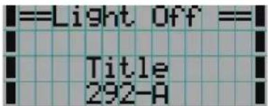
When the startup of the projector completes, the status of the POWER button, DOUSER button, LIGHT ON/OFF button, and preset button (button <1> to <8>) changes as follows.
| POWER button Lit green | |
| DOUSER button Initial settings: Off (douser is off) | |
| LIGHT ON/OFF button Initial settings: Blinking green (light source is off) | |
| Button <1> to <8> The preset button which was last selected is lit green | |
6 Press the LIGHT ON/OFF button on the control panel for three seconds or longer.
The light source is turned on and the screen glows light about 15 seconds later.
The LIGHT ON/OFF button indicator blinks in cycles of 2 (and changes to steady green light 90 seconds later).
The douser is closed until the screen glows light (the DOUSER button indicator lights green). When the douser is open, the DOUSER button indicator turns off.
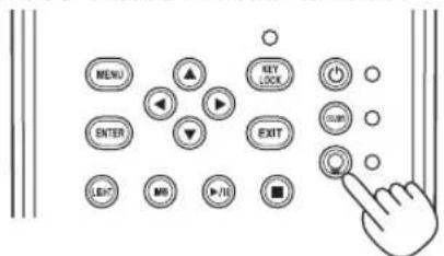
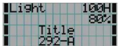
NOTE
- While your projector is on, be sure to have the lens cap and glass protector cap removed from the lens. Otherwise, the lens cap or glass protector cap may get deformed due to a heat buildup.
- In the following instances, the power to your projector cannot be turned on even if you press the POWER button. - When the inside temperature is abnormally high. The protective function prevents power from turning on. Wait some time (until the projector inside cools down) and then turn on the power.
- When the SYSTEM status indicator is blinking in red without the light source lighting up after power-on. Your projector may be in trouble. Check the error display on the LCD screen and contact your dealer/distributor for instructions.
3-3. Selecting the title of input signal
This projector allows you to select pre-registered title (input signal) using the preset buttons on the control panel (up to 16 titles). Request your dealer/distributor for details on registering and changing titles. This section explains the steps for selecting registered titles.
1 Turn on the power to the image devices connected to the projector.
2 Press the MENU button.
3 Press the LEFT/RIGHT button to display "Title Select" on the LCD screen.
At each press of the LEFT/RIGHT buttons, the display will cycle as "Title Select" "Configuration" "(Title Setup)" "Information."
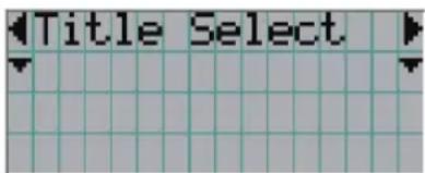
4 Press the DOWN button.
The title of the input signal is displayed.
- When you have made a wrong selection, press the UP button. A return will be made to the previous menu.
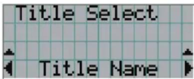
5 Press the LEFT/RIGHT buttons to display "Title of Signal to be Projected" on the LCD screen.
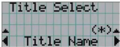
6 Press the ENTER button.
The title of the signal to be projected is selected.
- The (*) mark on the LCD indicates that this is the currently selected item.
3-4. Adjusting the position and the size of projected screen
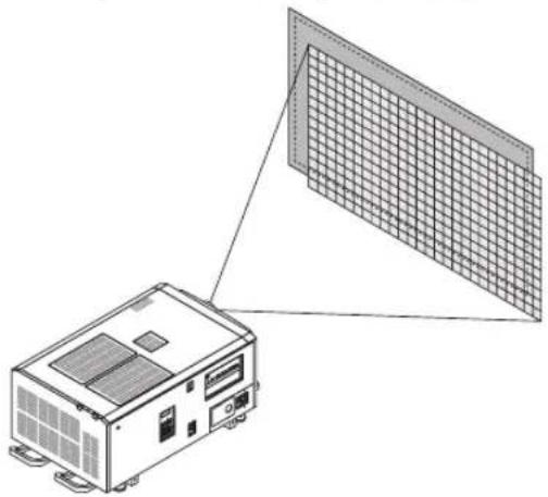
3-4-1. Displaying the test pattern
1 Press the MENU button, or select a test pattern from preset buttons (button <1> to <8>).
If you register the test patterns to the preset buttons (<1> to <8> buttons), select the test pattern according to "3-3. Selecting the title of input signal (See page 35)".
natural_image
Diagram of an electronic device with a grid-patterned panel and connected to its base (no text or symbols)2 Press the LEFT/RIGHT button to display "Title Select" on the LCD screen.
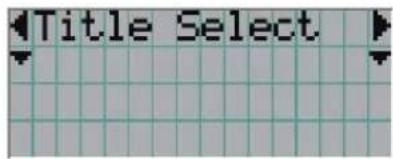
3 Press the DOWN button.
The title of the input signal is displayed.
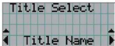
4 Press the LEFT/RIGHT button to display "TEST Pattern" on the LCD screen.
5 Press the DOWN button.
The LCD screen enters the mode where you can select a test pattern.
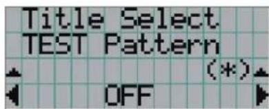
6 Press the LEFT/RIGHT button.
This switches the test pattern name displayed on the LCD screen.
7 Display on the LCD the name of the test pattern to be projected, then press the ENTER button.
The test pattern is displayed.
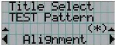
To cancel the test pattern display, select the title of the signal to project or select the "OFF" test pattern.
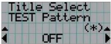
3-4-2. Adjusting the position of the projected screen (Lens shift)

CAUTION
- Perform the adjustment from behind or from the side of the projector. If adjustments are performed from the front, your eyes could be exposed to strong light and get injured.
1 Press the MENU button.
2 Press the LEFT/RIGHT button to display "Configuration" on the LCD screen.
3 Press the DOWN button.
4 Press the LEFT/RIGHT button to display "Lens Control" on the LCD screen.
5 Press the DOWN button.
The screen ("Lens Position") to adjust the position of the projected screen is displayed.
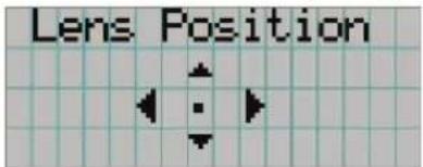
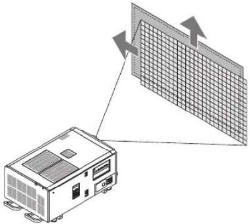
6 Press the UP/DOWN/LEFT/RIGHT button.
The position of the projected screen moves in the selected direction.
natural_image
Diagram showing a device connected to a grid panel with directional arrows (no text or symbols)7 Press the EXIT button when adjustment is complete.
The display will return to a menu one level above (where "Lens Control" is displayed).
3-4-3. Adjustment of the size (zoom) and focus of the projected screen
1 Press the MENU button.
2 Press the LEFT/RIGHT button to display "Configuration" on the LCD screen.
3 Press the DOWN button.
4 Press the LEFT/RIGHT button to display "Lens Control" on the LCD screen.
5 Press the DOWN button.
The screen ("Lens Position") to adjust the position of the projected screen is displayed.
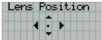
6 Press the ENTER button.
The screen to adjust the size and focus of the projected screen is displayed.
Press the ENTER button to switch the display between "Lens Position" and "Focus Zoom" adjustments.

flowchart
graph LR
    A["Lens Position"] -->|ENTER button| B["Focus"]
    B --> C["Zoom"]
7 Adjust the size and focus of the projected screen.
Press the UP/DOWN button to adjust the focus.
Press the LEFT/RIGHT button to adjust the size.
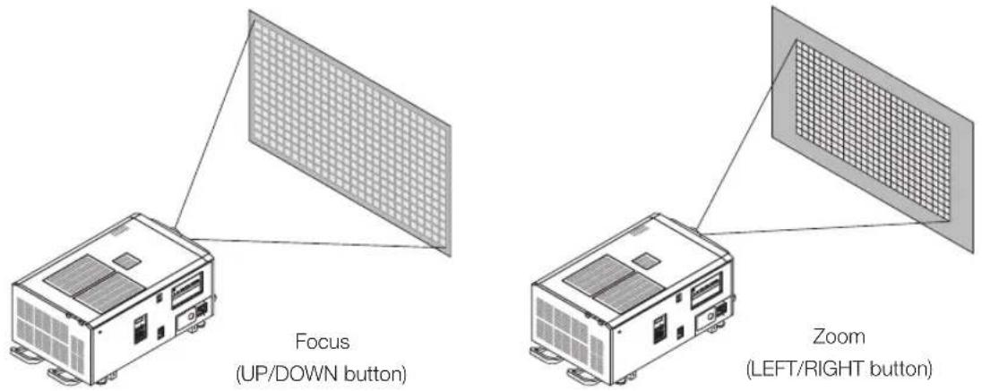
8 Press the EXIT button when adjustment is complete.
The display will return to a menu one level above (where "Lens Control" is displayed).
3-4-4. Adjusting the brightness of the projected screen (Light output)
NOTE
If the internal temperature within the projector rises due to the temperature in the room being high, the light output may be automatically reduced. This is called "Thermal Protection Mode (Down Light Power)". When the projector is in the Thermal Protection Mode, the picture brightness decreases slightly. To clear Thermal Protection Mode, adjust the light output. Consult with your dealer/distributor for details.
1 Press the LIGHT button.
The screen to adjust the light output is displayed.
![MENU ENTER EXIT NO EXIT NO EXIT KEY LOCK COUNTER EXIT Light Setup Adjust (*)# 100 [%]](/content/2026/05/1059255/images/8acdcc17db029bfa74bf05a6a8ec074da4eb6d917204b9ca0c3d02eefceb0f41.jpg)
2 Press the LEFT/RIGHT button to adjust the light output.
The specified adjustment value is applied.
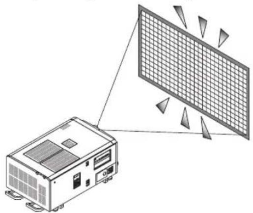
natural_image
Diagram showing a device connected to a grid-patterned panel array (no text or symbols)3-5. Preventing misoperations
Buttons on the control panel can be locked (KEY LOCK) to prevent misoperations. Buttons on the control panel do not function while KEY LOCK is on. KEY LOCK must be off to operate these buttons.
NOTE
• KEY LOCK is automatically turned on in the following cases.
- When the projector has entered the standby state by turning on the main power switch of the projector while the AC power is supplied.
- When the projector has entered the standby state after turning off the power using the POWER button.
- The timing where KEY LOCK is turned on while the projector is in standby state depends on the "Auto Key Lock" setting in the adjustment menu.
- When Auto Key Lock is enabled, KEY LOCK becomes automatically on if no control panel operation takes place in the standby state for 30 seconds. KEY LOCK becomes automatically on again even after KEY LOCK is turned off if no control panel operation takes place for 30 seconds.
- When Auto Key Lock is disabled, KEY LOCK becomes automatically on when the projector enters the standby state; however, it stays off after KEY LOCK is turned off.
3-5-1. KEY LOCK setting
- Press the KEY LOCK button on the control panel for one second or longer.
KEY LOCK becomes on. The KEY LOCK button indicator lights orange. When you press a button on the control panel of the projector while KEY LOCK is on, "Panel is Locked. (KEY LOCK)" is displayed, and the button will not function. (See page 45)
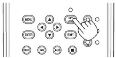
3-5-2. Turning KEY LOCK off
- Press the KEY LOCK button for one second or longer while KEY LOCK is on.
KEY LOCK becomes off. The KEY LOCK button indicator turns off.
3-6. Turning on/off the light with the projector turned on
3-6-1. Turning off the light
- Press the LIGHT ON/OFF button on the control panel for three seconds or longer.
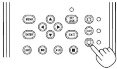
3-6-2. Turning on the light
- Press the LIGHT ON/OFF button on the control panel for three seconds or longer.
3-7. Turning your projector off
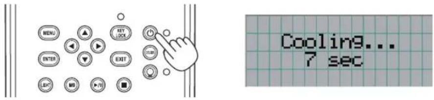
1 Press the POWER button on the projector control panel for three seconds or longer.
The light is turned off, the POWER button indicator blinks green, and the STATUS indicator blinks orange (cooling state). The fan will continue to rotate while cooling, and the amount of time remaining for cooling is displayed on the LCD screen. The cooling-off time is 90 seconds.
When the cooling is finished, the POWER button indicator turns off and the status indicator lights orange (standby state). KEY LOCK becomes automatically on if no control panel operation takes place in the standby state for 30 seconds by default. Buttons on the control panel do not function while KEY LOCK is on. (See page 40)
2 After the standby mode is set, turn off the projector's power switches in this order: first the projector power switch, then the light power switch.
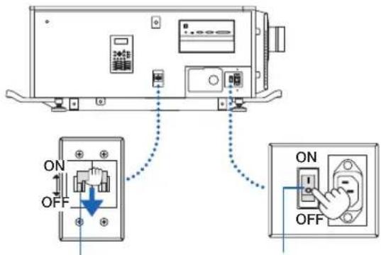
Light power switch Projector power switch
3 Turn the administrator key counterclockwise to the horizontal position, then remove it.
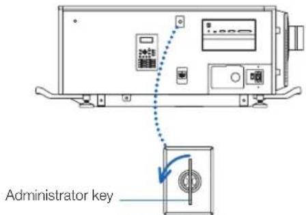
Administrator switch
4 Shut off the AC power supply to the main unit from the circuit breaker, etc.
NOTE
In the following instances, do not turn off the main power switch or disconnect the AC power. Doing so can damage the projector.
• While projecting images
• While the fan is running after the power is turned off
- While the projector is cooling down after the power was turned off.
- When using the IMB: 180 seconds
- During IMB operation (when the projector is not in the standby mode)
4.
Using Menus
4-1. Basic operation with adjustment menus
To adjust the projector, display the menu on the LCD screen of the projector control panel.
4-1-1. Screen display
The menu display screen is composed of a menu display field (the upper two lines) and a setting item display field (the bottom two lines).
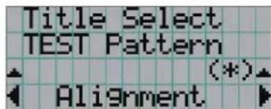
← Displays the main menu or submenus.
← Displays submenus or selection items.
← Displays settings and selection status.
← Displays settings, selected items and information on selected menus.
The meanings of symbols in the menu display screen are outlined below.
 | Indicates that there is a menu of a higher level.Press the UP button to return to a menu one level above. |
 | Indicates that there is a selected item or menu at the same level.Press the LEFT/RIGHT button to display other selected items or menus. |
 | Indicates that there is a menu of a lower level.Press the DOWN button to display the menu one level below. |
 | Indicates that there are setting items of a higher or lower level.Press the UP button to return to a menu one level above.Press the DOWN button to display the setting item one level below. |
When not displaying menus, the following screen is normally displayed.
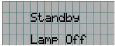
When in standby
When the projector is in a standby state (the main power switch in on), the following is displayed.
When power is turned on
When the power is turned on, the following is displayed.
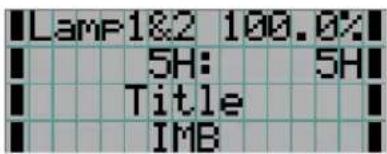
← Displays the light mode and light output (%).
← Displays the light usage time.
← Displays the selected title.
← Displays the selected video input port.
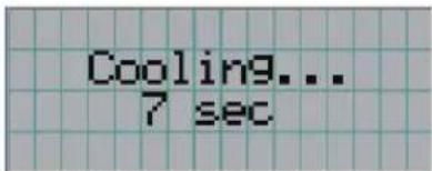
When the power is turned off
When you press the POWER button on the control panel of the projector for 3 or more seconds, the projector starts cooling. When cooling finishes, the projector enters the standby mode. The amount of time remaining for cooling is displayed as shown below during cooling.
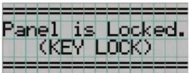
When a button is pressed while the key lock function is on
If a button on the control panel is pressed while the key lock function is on, the following is displayed and the button will not function.
4. Using Menus
4-1-2. Operating menus
Preparation: Turn your projector on. (See page 33)
1 Press the MENU button on the control panel of your projector.
The menu is displayed in the LCD screen.
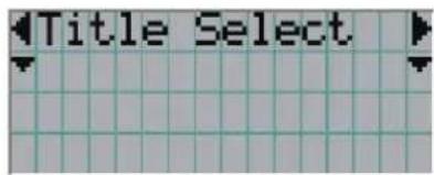
2 Press the LEFT/RIGHT buttons to display "Information."
At each press of the LEFT/RIGHT buttons, the display will cycle as "Title Select" "Configuration" "(Title Setup)" "Information."
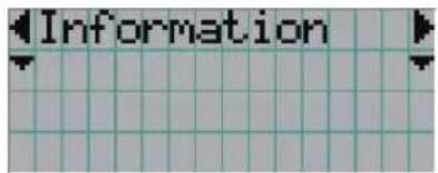
3 Press the DOWN button.
The submenu "Light" of "Information" is displayed.
The menu item can be selected by pressing the ENTER button instead of the DOWN button.
To return to the previous state, press the UP button, or the EXIT button.
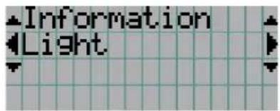
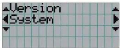
4 Press the LEFT/RIGHT button to select the submenu "Version."
At each press of the LEFT/RIGHT button, the display will cycle as "Light" "Lens Type" "Preset Button" "Usage" "Error Code" "Version" "IP Address" "Setup Date" "Option Status."
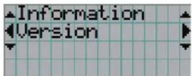
5 Press the DOWN button.
The submenu "System" another rank lower than "Version" is displayed.
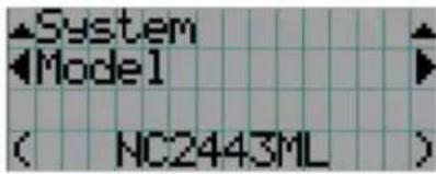
6 Press the DOWN button.
The submenu "BIOS" another rank lower than "Model" is displayed.
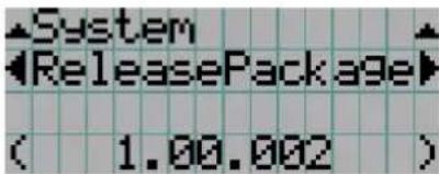
7 Press the LEFT/RIGHT button to select the submenu "Release Package."
At each press of the LEFT/RIGHT button, the display will cycle as "Model" "Serial No." "Release Package" "Kernel" "U-Boot" "System Files" "CinemaFirmware" "Cinema Data" "ICP Firmware" "ICP ConfigFile" "FMT FPGA" "Secure Processor" "Slave BIOS" "Slave Firmware" "Opt MCUFirmware" "LD Interface" "LD Driver1" "LD Driver2" "LD Driver3" "LD Driver4" "LD Driver5" "LD Driver6" "LD Driver7" "LD Driver8" "Lens Firmware" "Keypad MCU" "Router" and each version information is displayed.
8 Press the UP button several times.
At each press of the UP button, the display will return to a menu one level above.
4-1-3. How to enter alphanumeric characters
Alphanumeric characters are entered for items, such as the log file of the specified period is written to USB memory. (See page 66) Characters can be entered by pressing numeric buttons on the control panel on this projector.
Move right and left Delete entered characters
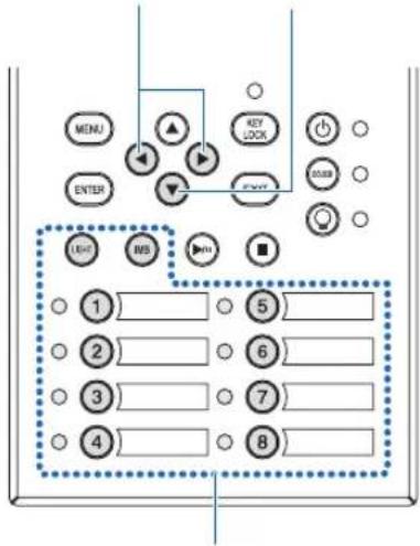
Enter characters
Characters can be entered by pressing each button as shown in the following table.
• To delete a character during entry, press the DOWN button.
[Example of Entry]
To enter "XGA" for example, use the following procedure:
$$ \begin{array}{c c} \mathsf {V} & \to \mathsf {W} \to \mathsf {X} \end{array} $$
(1) Press the "8" button three times.
(2) Press the RIGHT button.
(3) Press the "3" button.
XG
(4) Press the RIGHT button.
(5) Press the "1" button.
XGA
| Button Entered character | |
| 1 | A→B→C→1→a→b→c→!→↑ |
| 2 | D→E→F→2→d→e→f→“→↑ |
| 3 | G→H→I→3→g→h→i→#→↑ |
| 4 | J→K→L→4→j→k→l→$→↑ |
| 5 | M→N→O→5→m→n→o→%→↑ |
| 6 | P→Q→R→6→p→q→r→&→↑ |
| 7 | S→T→U→7→s→t→u→’→↑ |
| 8 | V→W→X→8→v→w→x→(→↑ |
| LIGHT | Y→Z→/→9→y→z→?→)→↑ |
| IMB | *→,→.→0→;→:→+→-→↑ |
4-2. Table of adjustment menus
Menus in parentheses are menus for our service personnel. Normally, these menus cannot be used.
| Main menu Submenu Description | Reference page | |||
| Title Select "Title Memory Name" Selects the title of the signal to be projected. 51 | ||||
| TEST Pattern Selects the test pattern to be projected. 51 | ||||
| Configuration Light Setup Adjust Adjusts light brightness. 52 | ||||
4. Using Menus
| Main menu Submenu Description | Reference page | |||
| Information | Light Light Output Displays the light module's brightness (output) setting value. | 54 | ||
| 54 | ||||
| 54 | ||||
| S/N Displays the serial number of the light module. | 54 | |||
| Lens Type This function cannot be used. - | ||||
| Preset Button Preset | Button 1-16 Displays the titles which are assigned to the preset buttons (<1> to <8> buttons). | 55 | ||
| Usage Displays information related to projector usage. 55 | ||||
| Error Code Displays the currently occurring error. 55 | ||||
| Version | System | Displays the model name and various version information about the projector. | 56 | |
| IMB | Displays the vendor name and version information about the media block (IMB). | 56 | ||
| IP Address | System | Displays the IP address of the projector. | 56 | |
| Setup Date | Displays the date when the projector was set up (starting date of the warranty period). | 57 | ||
| Option Status | Displays the link status of the device mounted in slot and projector. | 57 | ||
(Note) Requires logging into the projector with Advanced User or higher privileges.
4-3. Title Select
4-3-1. Title select (Title Memory)
Selects the title of the signal to be projected.
You can register up to 100 titles. You can also assign registered titles to the preset buttons (<1> to <8> buttons) on the projector's control panel and call them up directly using those buttons.
Request your dealer/distributor for details on registering and changing titles.
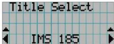
← Displays the currently selected item with asterisk (*).
← Selects the title to be projected.
4-3-2. Test Pattern
Selects the test pattern to be projected.
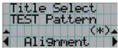
← Displays the currently selected item with asterisk (*).
← Selects the test pattern to be projected.
OFF, Alignment, Cross Hatch, Convergence, Red, Green, Blue, White, Black, White 50% [IRE], H-Ramp, Logo, MCG CG-TEST
4. Using Menus
4-4. Configuration
Please request your dealer/distributor to perform the settings.
4-4-1. Light Setup
Adjust
Adjusts the light output (brightness).
← Displays the current output power value (%) when the light rated output is 100%.
4-4-2. Lens Control
Adjust the position, size, and focus of the projected screen.
Press the ENTER button to switch the display between "Lens Position" and "Focus Zoom" adjustments. Press the EXIT button to return to a menu one level above.
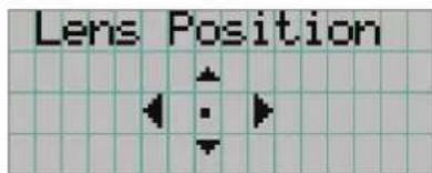
Lens Position
Adjusts the position of the projected screen.
The projected screen moves in the selected direction as you press the UP/DOWN/LEFT/RIGHT button.
Focus Zoom
Adjusts the size (Zoom) and focus (Focus) of the projected screen.
Press the UP/DOWN button to adjust the focus.
Press the LEFT/RIGHT button to adjust the size of the projected screen.
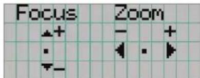
4-4-3. Reset
This is used to reset the light and air filter usage times.
Filter Cleaning
Resets the air filter usage time (for confirming the filter cleaning time).
[1] Press the ENTER button, the confirmation screen will appear.
[2] Select "Yes" in the confirmation screen, and then press the ENTER button to reset the filter usage time.
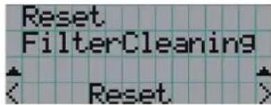
← Press the ENTER button to display the confirmation screen.
4-4-4. Installation
Lens Type
This function cannot be used.
Lens Calibrate
Performs calibration on lenses that support the lens memory function. Once you have attached a lens that supports the lens memory function, always execute calibration. This menu item is available only when the projector power is turned on and you are logged into the projector with Advanced User or higher privileges.
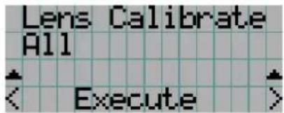
← Press the ENTER button to execute calibration.
| All Calibrates the zoom, focus and lens shift position. |
| Zoom&Focus Calibrates the zoom and focus. |
| Shift(H&V) Calibrates the lens shift position. |
Lens Center
To move the lens shift to the center position. The center position may slightly shift depending upon mounting conditions of the lens. This menu item is available only when the projector power is turned on and you are logged into the projector with Advanced User or higher privileges.
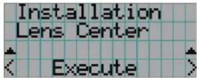
← Press the ENTER button to execute moving.
4. Using Menus
4-5. Title Setup
Sets the title to be assigned to the preset buttons (<1> to <8> buttons) (up to 16 titles).
Request your dealer/distributor to perform the settings.
4-6. Information
Displays the hours of light use, the version information and error codes.
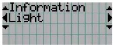
4-6-1. Light
Displays the information of Light module.
![Light Light Output ( 100.00 [%] )](/content/2026/05/1059255/images/30bb701348ddda6ae8b8b22c3925d81572fb9f144057404dfce27838adc8c364.jpg)
← Displays the current setting (%).
| Light Output Displays the light module's brightness (output) setting value. |
| Model Displays the light module's model name. |
| S/N Displays the serial number of the light module. |
4-6-2. Lens Type
This function cannot be used.
4-6-3. Preset Button
Sets the title to be assigned to the preset buttons (<1> to <8> buttons) on the projector's control panel.
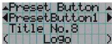
← Selects the preset button number whose contents you want to display.
← Displays the assigned title numbers.
← Displays the registered names of the assigned titles.

To select a title allocated to one of "Preset Button9" to "Preset Button16", press the preset button while holding down the UP button. For example, to select the title allocated to "Preset Button9", press the <1> button while holding down the UP button.
4-6-4. Usage
Displays information related to the projector usage, such as the usage time of the projector, light, air filters, and fan, and information about the light replacement cycle.
![Usage Projector Total 0 [H] ( 0 [H] )](/content/2026/05/1059255/images/5f10ff3c22fb010dc5f1fba86d389ef06b21dc894b0067c83c4a2b2811631ead.jpg)
← Selects the item to display.
← Displays information about the selected item.
| Projector | Displays the usage time of the projector.The upper row shows the usage time including standby mode while the lower row shows the usage time not including standby mode. |
| Filter Cleaning Displays the fan | air filter usage time. |
| Fan Usage Displays the fan | usage time. |
| Light Usage Displays the usage time of the light source. | |
| Phosphor Displays the usage time of the phosphor. | |
| Diffuser Displays the diffuser usage time. | |
| Pump Displays the pump usage time. | |
| Douser Count Displays the number of times the douser has been used. | |
4-6-5. Error Code
Displays the error code when an error occurs.
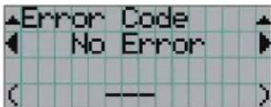
← Displays the code of the error currently occurring.
← Displays the name of the error currently occurring.
When multiple errors occur, you can display them by pressing the LEFT/RIGHT buttons.
4. Using Menus
4-6-6. Version
Displays version information about the projector, optional boards, and IMB.
System
Displays the version information of the projector.
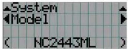
← Selects the item to display.
← Displays the version information.
- Model
- Opt MCUFirmware
- Serial No. - LD Interface
- Release Package
- LD Driver1
- Kernel - LD Driver2
- U-Boot
- LD Driver3
- System Files
- LD Driver4
- CinemaFirmware
- LD Driver5
- Cinema Data
- LD Driver6
- ICP Firmware - LD Driver7
- ICP ConfigFile - LD Driver8
• FMT FPGA • Lens Firmware - Secure Processor
- Keypad MCU
- Slave BIOS
- Router
- Slave Firmware
IMB
Displays the vendor name and version information about the media block (IMB). When the projector is in standby mode, the vendor name is blank and the version information displays “---”.
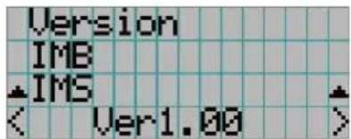
← Displays the vendor name.
← Displays the version information.
4-6-7. IP Address
Displays the IP address set in the projector.
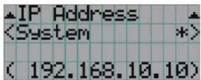
4-6-9. Option Status
Displays the link status of the device mounted in slot on the projector. The device name is displayed in ( ) when the projector is in standby or when connection to the device cannot be confirmed.  ← Displays the link status of the device in slot. • NP-90MS: NP-90MS02 •5.
Maintenance of Your Projector
NOTE Please request your dealer to perform cleaning of the projector inside.5-1. Cleaning the Cabinet
WARNING
Pull out the power plug from the power outlet before cleaning the cabinet. WARNING
Please do not use a spray containing flammable gas to remove dust attached to the cabinet, etc. Doing so may result in fires. - Wipe with a dry, soft cloth without nap. When the cabinet is excessively dirty, wipe with cloth well wrung after being dampened with a neutral detergent diluted with water and then finish up with a dry cloth. When you use a chemical dust cloth, follow the instructions in the manual attached to it. - Do not use a solvent, such as thinner or benzene. The coating may deteriorate or peel off. - When removing dust on the ventilation opening, suck it off using an adapter with a brush on a vacuum cleaner. Never allow the cleaner without an adapter to come into direct contact or use a nozzles adapter in cleaning. - Clean the ventilation opening at regular intervals. Dust, if allowed to accumulate there, may cause heating inside, which leads to functional trouble. The interval, which can vary with the location of your projector, is about 100 hours. - Do not damage the cabinet by scratching it or allowing hard objects to hit it. This can scratch the projector. - Consult your dealer/distributor about cleaning the inside of the projector. NOTE Do not allow insecticide or other volatile liquid to splash on the cabinet, lens or screen. Also, do not allow any rubber or plastic object to remain in contact with the cabinet for a long time. The coating may deteriorate or peel off.5-2. Cleaning the Lens
Clean the lens the same way as with camera lens (using a commercially available camera blower or cleaning paper for glasses). Take care not to damage the lens when cleaning. WARNING
Pull out the power plug from the power outlet before cleaning the lens. WARNING
- Do not look into the light module while the projector is ON. Strong light is emitted from the projector and visual impairment could result. - Please do not use a spray containing flammable gas to remove dust attached to the lens, etc. Doing so may result in fires.5-3. Cleaning the Air Filters
Air filters are provided on the projector's air intakes to prevent dust from entering the projector. Clean the air filters regularly to maintain the performance of the projector. \- The usage time of the air filters can be checked at "Information" - "Usage" (page 55) on the adjustments menu. WARNING
Pull out the power plug from the power outlet before cleaning the air filters. WARNING
- If dust accumulates on the air filters, air intake to the projector will be insufficient and the internal temperature will rise, leading to fire or malfunction. - Do not use a flammable gas spray to remove dust from the filters. Doing so may lead to fire. CAUTION
\- Before cleaning the air filters, turn off the power, wait for the cooling fan to come to a complete stop, turn off the projector power switch and the light power switch, interrupt the AC power supply, and make sure that the projector has cooled sufficiently. Removing the filter units during operation may cause burns or electric shock if the inside is touched. 5. Maintenance of Your Projector
To remove the front air filter, pull the filter cover in the direction of the arrow. To install, insert the catches in the filter cover into the grooves in the lens cover, close the cover, then push it in.   The illustration in this explanation shows how to clean the air filters on the top panel. Clean the other filters in the same way as these air filters (small type).1 Remove the air filter.
Turn the 2 screws counterclockwise until they are disengaged, then lift the air filter a little to remove it. - The screws do not come off. - The number of screws differs depending on the air filter.2 Remove the metal filter.
Note: The metal filter does not come off the small type air filters. See "For small type air filters" on the next page. (1) Turn the air filter upside down. (2) Slowly bend the metal filter a little to unlatch the three catches from the grooves in the panel one by one. Note: Bending the metal filter too much could damage it beyond repair. Be very careful to only bend the metal filters a little when removing them. (3) Remove the metal filter from the panel.3 Use a vacuum cleaner to remove the dust.
Use a vacuum cleaner to remove the dust from both sides of the metal filter, the projector and the panel. Note: Do not wash the metal filter in water. Doing so will cause the dust to clog the holes, reducing intake performance. natural_image
Technical diagram showing two views of a grid structure with directional arrows indicating rotation or movement (no text or symbols present)natural_image
Four-step diagram showing a cleaning or surface treatment procedure: top panel with grid lines, bottom panel with brush applying paint, middle panel with blue arrow indicating direction, and bottom panel with brush applying paint (no text or symbols)natural_image
Technical line drawing of a mechanical assembly with a tool interacting with a grid-patterned component (no text or symbols)4 Attach the metal filter.
(1) Insert the three catches on the metal filter into the grooves in the panel. (2) Bend the metal filter a little and insert the three projecting parts on the opposite side into the grooves in the panel, one by one. Note: Bending the metal filter too strongly could damage it, rendering it unusable. Be very careful to only bend the metal filters a little when attaching them.5 Attach the air filter to the projector.
(1) Insert the catches in the air filter into the grooves in the projector. (2) Turn the two screws clockwise to tighten them. The number of screws differs depending on the air filter. This completes cleaning of one of the air filters. Clean the other air filters in the same way.6 Reset the air filter usage time.
See "Filter Cleaning" under "Reset" on Page 52.For small type air filters
1. Using the procedure in step 1, turn one screw counterclockwise until it is disengaged, then lift the air filter (small type) a little to remove it. The screws do not come off. 2. Use a vacuum cleaner to remove the dust. Use a vacuum cleaner to remove the dust from both the front and back sides of the filter and from the projector.Note:
- Do not remove the metal filter. Doing so may bend it, rendering it unusable. - Do not wash the air filter in water. Doing so will cause the dust to clog the holes, reducing intake performance. 3. Using the procedure in step 5, turn one screw clockwise to tighten it. NOTE Locate the back side of the air filter and install it in the designated place. 4. Perform the operation in step 6.   natural_image
Isometric diagram of a grid-patterned structure with directional arrows and blue curved arrows indicating movement or force (no text or symbols)natural_image
Isometric view of a rectangular device with multiple slots and mounting feet (no text or symbols)natural_image
Illustration of a hand brushing a textured surface on a tray (no text or symbols)natural_image
Pure technical diagram of a structural grid with no text, numbers, or symbols6.
Appendix
6-1. Troubleshooting
Before asking for repair, please check your connection, settings and operation once again. If the trouble cannot be corrected, please contact your dealer/distributor for instructions or repair.6-1-1. Problems and where to check
| Problem Check these items | |
| The projector cannot be turned on. Check to see if AC power is supplied to the projector. | |
| Is the temperature inside the projector too high? When the inside temperature is too high, the protective function does not allow your projector to be turned on. Wait some time and then turn it on. | |
| Is the administrator key inserted? The projector will not function unless the administrator key is inserted. | |
| The image cannot be projected. Check to see if the connected input has been selected. | |
| The image is distorted. Check to see if the protractor is properly set up. | |
| The image is blurred. Make certain that the lens is properly focused. | |
| Video image is disturbed. Check whether the signal cable connected to the projector is disconnected. | |
| The STATUS indicator blinks in red. | Your projector may have trouble. Please contact your dealer/distributor for instructions. |
| An error code is displayed. Please contact your dealer/distributor for instructions. | |
6-2. Indicator display list
See the descriptions below when the buttons on the control panel or the STATUS indicator on the rear of the projector is lit or blinking. The projector also has a warning function that uses a buzzer. 6-2-1. Preset buttons
| Indicator condition Projector condition Note | ||
| Off No title is assigned to the button. - | ||
| Steady light A title is assigned to the button. - | ||
| Green The title is being selected. - | ||
| White The title is not selected. - | ||
6-2-2. KEY LOCK button
| Indicator condition Projector condition Note | |||
| Off The key lock is off. - | |||
| Steady light Orange | The key lock is on. - | ||
6. Appendix
6-2-3. POWER button
| Indicator condition Projector | condition Note | ||
| Off The projector power supply is off. - | |||
| Blinking light Orange | While the projector | software is starting Wait for a moment. | |
| Green(cycles of 1) (Note 1) | Preparing to turn power on/cooling fan rotating(State from turning the power off to entering standby mode). | Wait for a moment. | |
| Green(cycle of 3 seconds)(Note 2) | When the sleep timer is activated - | ||
| Steady light Green | The projector is turned on. - | ||
| Orange The projector is in standby. - | |||
6-2-4. DOUSER button
| Indicator condition Projector condition Note | ||
| Steady light Green | The douser is closed. - | |
| Off The douser is opened. - | ||
6-2-5. LIGHT ON/OFF button
| Indicator condition | Projector condition Note | ||
| Off The light is off. | - | ||
| Steady light Green | The light is on. | - | |
6-2-6. STATUS indicator
SYSTEM status indicator
| Indicator condition Projector condition Note | |||
| Off Main power is off. - | |||
| Blinking light Green | The projector is getting ready to turn on.The douser is closed.The light is off. | Wait for a moment. | |
| Orange The projector is cooling down. Wait for a moment. | |||
| Red (With buzzer) Safety problem, error. An error message is displayed in the | LCD screen.Check the content of the error. | ||
| Red (Without buzzer) Error with possible image project under certain conditions. | |||
| Steady light Green | The projector is turned on. - | ||
| Orange The projector is in standby. - | |||
| Red | Error at a level with not affect on projection. | An error message is displayed in the LCD screen.Check the content of the error. | |
LIGHT status indicator
| Indicator condition Projector condition Note | ||
| Off The light source is off. | - | |
| Steady light | The light source is on. | - |
6-3. Operation using an HTTP browser
6-3-1. Overview
The use of HTTP server functions will allow control of the projector from a web browser. Please be sure to use "Microsoft Internet Explorer 4.x" or a higher version for the web browser. This device uses "JavaScript" and "Cookies" and the browser should be set to accept these functions. The setting method will vary depending on the version of the browser. Please refer to the help files and the other information provided in your software.NOTE
The display's or button's response can be slowed down or operation may not be accepted depending on the settings of your network. Should this happen, consult your network administrator. The projector may not respond if its buttons are repeatedly pressed in rapid intervals. Should this happen, wait a moment and repeat. Access is gained to the HTTP server functions by and specifying http://6-3-2. Preparation before use
Make network connections and set up the projector and confirm that it is complete before engaging in browser operations. Operations with a browser that uses a proxy server may not be possible depending on the type of proxy server and the setting method. Although the type of proxy server will be a factor, it is possible that items that have actually been set will not be displayed depending on the effectiveness of the cache, and the contents set from a browser not be reflected in operation. It is recommended that a proxy server not be used unless it is unavoidable.6-3-3. URL for connecting to the HTTP server
Normally, the URL of the HTTP server is "http://6-3-4. Structure of the HTTP server
  | Power Controls the power to your projector. | On: Turns the power on.Off: Turns the power off. | ||
| Light Turn the light on/off. | On: Turns the light on.Off: Turns the light off. | ||
| Title List Displays titles set in the projector(such as input port, screen type, and title).Check, and the title will be changed. | |||
| Basic Control Displays the basic control items. | |||
| Lens Controls the lens operation. | |||
| Shift | ▲: Shifts the projected screen upward.▼: Shifts the projected screen downward.◀: Shifts the projected screen leftward.▶: Shifts the projected screen rightward.■: Stops the shifting.Shifting can also be stopped by clicking the same button one more time. | ||
| Zoom | ▲: Zooms up the lens.▼: Zooms down the lens.■: Stops the zooming.Zooming the can also be stopped by clicking the same button one more time. | ||
| Focus | ▲: Focuses up the lens.▼: Focuses down the lens.■: Stops the focusing.Focusing can also be stopped by clicking the same button one more time. | ||
| Mute Picture Click and the douser closes and the projected picture disappears. Click once again and the picture will be projected again. | |||
| Projector Status Displays the condition of the projector. | |||
| Light Memory Entry Saves the current light output value in the memory. | |||
6. Appendix
6-4. Writing of the log file (Save Information)
Log files saved on the main unit can be written to USB memory connected to the USB port of the main unit. To perform the writing of the log file, use the following procedure.1 Connect the USB memory to the USB port of the main unit.
Wait until the USB memory is recognized, and it enters the condition in which it can be used (5 or more seconds). For details, refer to the instruction guide of the USB memory.2 Simultaneously press the UP button and ENTER button.
The "Save Info." screen is displayed.  TIP If you press the EXIT button during operation, operation is stopped and the display returns to the normal screen.3 Press the LEFT/RIGHT button, and select the log file writing period.
The items that can be selected are as follows.| Today | Writes today's log files. |
| 7days Writes 7 days' log files from today. | |
| 30days | Writes 30 days' log files from today. |
| 2years | Writes 2 years' log files from today. |
| Manual Writes the specified period's log files. | |
4 Press the ENTER button.
When "Today", "7days", "30days" or "2years" is selected, the log file writing period is displayed.  ← The log file writing period is displayed. When "Manual" is selected, specify the log file writing period. For how to enter numerals, refer to "4-1-3. How to enter alphanumeric characters" (See page 50). If you press the ENTER button, the display advances to the following screen. flowchart
graph TD
    A["** Save Info. ** Date Filter From Date [2016/03/18 Fri"]] -->|Enter the date/time to start writing.| B["Press the ENTER button."]
    B --> C["** Save Info. ** Date Filter To Date [2016/12/21 Wed"]]
    C -->|Enter the date/time to stop writing.| D["Press the ENTER button."]
    D --> E["** Save Info. ** 2016/03/18 Fri 2016/12/21 Wed Execute"]
    E --> F["The log file writing period is displayed."]
6-4-1. Names of log files
Written log files are saved with the following file names. (Model name)\_(Serial Number)\_YYMMDDHHmm.txt| (Model name) | This shows the model of projector. |
| (Serial Number) | This shows the serial number of projector. |
| YYMMDDHHmm Shows the date/time when written.YY: Year (lower 2 digits)MM: Month (2 digits)DD: Date (2 digits)HH: Hour (2 digits)mm: Minute (2 digits) | |
6-5. Outline Drawing
6-5-1. Projector  Units: mm6-6. Specifications
6-6-1. Projector| Model name DLP Cinema | *Projector Head : NP-42HD | ||||
| Light Module NP-24LU03 NP-20LU03 NP-18LU03 | |||||
| DLP Cinema® Projector NP-NC2443ML NP-NC2043ML | NP-NC1843ML | ||||
| Projection method 3 chip DLP Cinema | *method | ||||
| 0.98-inch DC4K chip | |||||
| Panel resolution 4096 x 2160 | |||||
| Light type Laser Diode | |||||
| Screen sizes | Max. 22 m Max. 20 m Max. 19 m | ||||
| @14ft-L / Screen Gain 1.8 (Depends on setup conditions) | |||||
| Contrast ratio 2000:1 with DCI specified color representation | |||||
| Lens adjustment function Motorized lens shift (vertical/horizontal), motorized zoom, motorized focus, douser | |||||
| Signal input ports When shipped from factory: Empty (for mounting optional components) (Note 1) | |||||
| External Control RS-232C (D-sub 9pin) x 1 | USB (Type A) x 1GPIO port (D-sub 37 pin) x 1Interlock port x 1Service terminal (stereo mini jack) x 1Ethernet port (G-bit RJ-45) x 13D CTL (D-sub 15 pin) x 1 | ||||
| Power supply voltage | |||||
| With a C1 connection (Note 3) | Projector power supply + Light power supply | Single-phase AC 200V-240V 50/60Hz | |||
| With a C2 connection (Note 3) | Projector power supply | Single-phase AC 100V-240V 50/60Hz | |||
| Light power supply | Single-phase AC 200V-240V 50/60Hz | ||||
| Input current | |||||
| With a C1 connection (Note 3) | Projector power supply + Light power supply | 19.1A | |||
| With a C2 connection (Note 3) | Projector power supply | for AC 100 V | 7.0A | ||
| for AC 200 V | 3.5A | ||||
| Light power supply | 15.6A | ||||
| Power consumption | |||||
| With a C1 connection (Note 3) | Projector power supply + Light power supply | 3,182W | 3,146W | ||
| With a C2 connection (Note 3) | Projector power supply | 362W | 352W | ||
| Light power supply | 2,820W | 2,794W | |||
| Cooling method Air cooling system and liquid cooling system | |||||
| Noise level | 50 dB or less | ||||
| Installation | Orientation: Desk/ front, desk/ rear, ceiling/ front, ceiling/ rear | ||||
| Net weight | 153 kg (total weight of projector and NP-24LU03 or NP-20LU03 light module. Not including the lens.) | 144 kg (total weight of projector and NP-18LU03 light module. Not including the lens.) | |||
| Dimensions | 697 mm (width) x 1,095 mm (depth) x 509.5 mm (height) | ||||
| Environment Operating temperature: 10 to 35°C | Operating humidity: 10 to 85% (non-condensing)Storage temperature: -10 to 50°CStorage humidity: 10 to 85% (non-condensing)Operating altitude: 0 to 3000 m/9800 feet | ||||
6-7. Pin Assignment and Functions of Terminal
6-7-1. PC CONTROL connector (RS-232) (D-sub 9 pin)
This is an RS-232C interface for controlling the projector from a PC. The projector operates as a DCE (Data Communication Equipment), so use a straight cable when connecting to a PC.   | Pin No. RS-232C Signal Name Functions as RS-232C Projector Connector Operation | |||
| 1 CD Carrier detection Not used (N.C.) | |||
| 2 RXD Reception data Data transmission to an external device | |||
| 3 TXD Transmission data | Data reception from an external device | ||
| 4 DTR | Data Terminal ready (Note) | Connection to 6 pins | |
| 5 GND | Signal GND | Signal GND | |
| 6 DSR | Data set ready (Note) | Connection to 4 pins | |
| 7 RTS | Transmission request | SYSTEM: Hi-Z (Not used)CINEMA: Hi-Z (Used) | |
| 8 CTS | Transmission available SYSTEM: Fixed at -6.5 V (Not used)CINEMA: ±10.5 V (Used: Depends on communication status) | ||
| 9 RI | Ring indicator | Not used (N.C.) | |
6-7-2. External control connector (GP I/O) (D-sub 37 pin)
It is possible to control the projector with an external device and to control the external device from the projector using an external control connector (GPIO: General Purpose I/O Ports). Each pin is electrically separated from the projector internal circuits by a photo-coupler. 8 port input and 8 port output are available. Please contact your dealer/distributor regarding how to use and to operate them.  Pin view of female connector| Pin No. | Signal Name I/O Pin No. Signal Name I/O | ||||
| 1 GPIN1+(3D L/R Input Reference +) | IN 20 GPIN1- | (3D L/R Input Reference -) | IN | ||
| 2 GPIN2+(3D L/R Display Reference +) | IN 21 GPIN2- | (3D L/R Display Reference -) | IN | ||
| 3 GPIN3+(system reserved) IN 22 GPIN3-(system reserved) IN | |||||
| 4 GPIN4+(system reserved) IN 23 GPIN4-(system reserved) IN | |||||
| 5 EXT_GPIN1+(Control and Title Selection +) | IN 24 EXT_GPIN1- | (Control and Title Selection -) | IN | ||
| 6 EXT_GPIN2+(Control and Title Selection +) | IN 25 EXT_GPIN2- | (Control and Title Selection -) | IN | ||
| 7 EXT_GPIN3+(Control and Title Selection +) | IN 26 EXT_GPIN3- | (Control and Title Selection -) | IN | ||
| 8 EXT_GPIN4+(Control and Title Selection +) | IN 27 EXT_GPIN4- | (Control and Title Selection -) | IN | ||
| 9 GPOUT1+(External 3D L/R Output Reference +) | OUT 28 GPOUT1- | (External 3D L/R Output Reference -) | OUT | ||
| 10 GPOUT2+(system reserved) OUT 29 GPOUT2-(system reserved) OUT | |||||
| 11 GPOUT3+(system reserved) OUT 30 GPOUT3-(system reserved) OUT | |||||
| 12 GPOUT4+(Internal 3D L/R Output Reference +) | OUT 31 GPOUT4- | (Internal 3D L/R Output Reference -) | OUT | ||
| 13 EXT_GPOUT1+(Projector Ready/Busy +) | OUT 32 EXT_GPOUT1- | (Projector Ready/Busy -) | OUT | ||
| 14 EXT_GPOUT2+(Projector Error Status +) | OUT 33 EXT_GPOUT2- | (Projector Error Status -) | OUT | ||
| 15 EXT_GPOUT3+(IMB Play/End Status +) | OUT 34 EXT_GPOUT3- | (IMB Play/End Status -) | OUT | ||
| 16 EXT_GPOUT4+(Projector Heartbeat +) | OUT 35 EXT_GPOUT4- | (Projector Heartbeat -) | OUT | ||
| 17 NC (not connected) - 36 NC (not connected) - | |||||
| 18 GND | PWR 37 GND | PWR | |||
| 19 | GND | PWR | - | - | - |
Input Connector
• Using GPIO Control
Momentary "ON" pulse enables you to control projector. To enable "ON" pulse, hold it for at least 500 ms. Hold "OFF" for at least 500 ms before "ON". (See page 76) Here is function list to control projector by using GPIO port.| Pin No. Photo-coupler ON/OFF Function | ||||
| 1-20 ON/OFF 3D L/R timing signal input ON/OFF | ||||
| 2-21 ON/OFF 3D L/R display timing signal input ON/OFF | ||||
| 3-22 - System reserved (used internally) | ||||
| 4-23 - System reserved (used internally) | ||||
| 5-246-257-268-27 | 8-27 7-26 6-25 5-24 | The following functions apply depending on the combination of input terminals. | ||
| OFF OFF OFF ON | Power ON | |||
| OFF OFF ON | OFF Power OFF | |||
| OFF OFF ON | ON Light source ON | |||
| OFF ON OFF | OFF Light source OFF | |||
| OFF ON OFF | ON Image douser ON | |||
| OFF ON ON | OFF Image douser OFF | |||
| OFF ON | ON | ON | System reserved (used internally) | |
| ON OFF OFF | OFF Selects the title registered to the preset button 1 | |||
| ON OFF OFF | ON Selects the title registered to the preset button 2 | |||
| ON OFF ON | OFF Selects the title registered to the preset button 3 | |||
| ON OFF | ON | ON | Selects the title registered to the preset button 4 | |
| ON ON OFF | OFF Selects the title registered to the preset button 5 | |||
| ON ON OFF | ON Selects the title registered to the preset button 6 | |||
| ON ON | ON | OFF | Selects the title registered to the preset button 7 | |
| ON ON | ON | ON | Selects the title registered to the preset button 8 | |
NOTE
- The operation command coming from GPI/O port will be canceled when the projector is processing other tasks, such as light source cooling and switching title. - Set all other pins than those in use to "OFF". - The operation command is executed upon continuous input of the "ON" pulse for approximately 200 ms.6. Appendix
• Timing chart of GPIO control
Example of Select Preset Button  Example for turning the image douser (Douser) on other
| Time Period | Event Description | | ------------------- | ------------------------------------- | | 5-24/7-26 | On phase | | 6-25/8-27 | Off phase | | Approx. 200 ms | Approx. 200 ms | | Execute Image douser (Douser) ON | Action button labeled 'Execute Image douser (Douser) ON' |other
| Time Interval | Off Status | Approx. 500 ms | | ----------------- | ---------------- | -------------- | | First Interval | Off | 200 ms | | Second Interval | on | Not specified |other
| Time Interval | Off Status | Value | | ----------------- | -------------- | ------------ | | 6-25 | on | Approx. 200 ms | | 6-25 | off | Approx. 200 ms | | 5-24/7-26/8-27 | on | Approx. 200 ms | | 5-24/7-26/8-27 | off | Approx. 200 ms | | End | Execute Power Off | Approx. 200 ms |6. Appendix
Output Connector
• Using GPIO Control
You can use GPIO control for the projector's health check and error check. Also, you can use the output as the trigger to control external devices. The following functions are assigned to the pin number 13-32, 14-33, 15-34, and 16-35 (EXT\_GPOUT1 - EXT\_GPOUT4) as the default. You can change the assigned functions.| Pin No. | Photo-coupler ON/OFF Function | |
| 9-28 ON/OFF External 3D L/R timing signal output ON/OFF | ||
| 10-29 – System reserved (used internally) | ||
| 11-30 – System reserved (used internally) | ||
| 12-31 ON/OFF Internal 3D L/R timing signal output ON/OFF | ||
| 13-32 ON/OFF GPIO control status check | ON: GPIO control (input) is unavailable.OFF: GPIO control (input) is available. | |
| 14-33 ON/OFF Error check | ON: ErrorOFF: No error | |
| 15-34 ON/OFF IMB status check | ON: The content is being played.OFF: The content is stopped/paused. | |
| 16-35 ON/OFF Health check (heart beat) | ON and OFF are alternately output when operations are normal. | |
6-7-3. 3D connector (D-sub 15 pin)
This is used to connect a 3D image system to the projector.  Pin view of a female connector| Pin No. | Signal Name I/O Function | ||
| 1 +12V PWR Supplies power (+12V) to the 3D image system | |||
| 2 GNDC GND Ground | |||
| 3 GNDC GND Ground | |||
| 4 RS232_RX IN Data transmission from the 3D image system(1200 Baud, 8 bits, No Parity) | |||
| 5 RS232_TX OUT Data transmission to the 3D image system(1200 Baud, 8 bits, No Parity) | |||
| 6 CONN_3D_MODE+ OUT 3D mode status (+) | (Connects to the collector of the output transistor of the photo coupler inside the projector) | ||
| 7 CONN_SYNC+ OUT 3D L/R switching timing signal (+)(Connects to the collector of the output transistor of the photo coupler inside the projector) | |||
| 8 3D_INPUT_REFERENCE+ | IN 3D L/R timing signal (+)(Connects to the anode of the input diode of the photo coupler inside the projector) | ||
| 9 +12V PWR Supplies power (+12V) to the 3D image system | |||
| 10 3D_INPUT_REFERENCE- | IN 3D L/R timing signal (-)(Connects to the cathode of the input diode of the photo coupler inside the projector) | ||
| 11 3D_DISPLAY_REFERENCE+ | IN 3D L/R display timing signal (+)(Connects to the anode of the input diode of the photo coupler inside the projector) | ||
| 12 3D_DISPLAY_REFERENCE- | IN 3D L/R display timing signal (-)(Connects to the cathode of the input diode of the photo coupler inside the projector) | ||
| 13 CONN_3D_MODE- OUT 3D mode status (-) | (Connects to the emitter of the output transistor of the photo coupler inside the projector) | ||
| 14 CONN_SYNC- OUT 3D L/R switching timing signal (-)(Connects to the emitter of the output transistor of the photo coupler inside the projector) | |||
| 15 N/C | - Unused | ||
| Product name Model name | ||
| Lens | Zoom lens 1.20~1.80 | NC-60LS12ZW |
| Zoom lens 1.20~1.81 | NC-60LS12Z | |
| Zoom lens 1.40~2.05 | NC-60LS14Z | |
| Zoom lens 1.59~2.53 | NC-60LS16Z | |
| Zoom lens 1.90~3.25 | NC-60LS19Z | |
| Zoom lens 2.40~3.90 | NC-60LS24Z | |
| Zoom lens 3.90~6.52 | NC-60LS39Z | |
| Projector Head NP-42HD | ||
| Light Module Max. 22 m screen width NP-24LU03 | ||
| Max. 20 m screen width NP-20LU03 | ||
| Max. 19 m screen width NP-18LU03 | ||
- NP-24LU03/NP-20LU03/NP-18LU03
- NP-NC2443ML/NP-NC2043ML/ NP-NC1843ML
- WARNING
- CAUTION
- Laser Safety Caution
- Machine Noise Information Regulation - 3. GPSGV,
- FCC Information (for USA only)
- Supplier's declaration of conformity (for USA only)
- Important Safeguards
- Installation
- Power Supply
- Fire and Shock Precautions
- Cleaning
- Caution on Carrying the Projector/Handling the Optional Lens
- Light Module
- Cable information
- Installing the Projector
- Connecting the power cord to earth
- is not in Handling the power cord
- Lens shift, focus and zoom operations
- Disposing of your used product
- Outside the European Union
- For questions relating to unclear points or repairs
- In Europe
- In North America
- In China
- In Hong Kong and Taiwan
- In South Korea
- In Australia and New Zealand
- In Thailand, Singapore, Malaysia, Indonesia and Philippines
- Label Information
- About the laser module used in the light source
- CLASS 1 LASER PRODUCT
- WARNING RG3 PRODUCT
- RISK GROUP 3
- GROUPE DE RISQUE 3
- MISE EN GARDE
- RISIKOGRUPPE 3
- WARNUNG
- Laser radiation range/No entry range (HD: Hazard distance)
- Please heed all precaution for safety.
- To install the projector
- To use the projector
- Important Information 2
- What's in the Box? and the Names of the Projector Parts......16
- Installation and Connection....25
- Projection of Images (Basic Operation)....32
- Using Menus 44
- Maintenance of Your Projector 58
- Appendix 62
- 1.
- What's in the Box? and the Names of the Projector Parts
- 1-1. Features
- - DLP Cinema® projector
- • Employs a long life laser light source
- - Delivers reduced installation space and increased freedom through a more compact and lightweight body
- • Equipped with easy to use functions
- • Excellent dust-proof performance
- - Reduced running cost thanks to the use of metal filters
- 1-2. What's in the Box?
- 1-2-1. Projector
- 1-3. Names of the Projector Parts
- 1-3-1. Front of the projector
- LIGHT status indicator
- SYSTEM status indicator
- Light power switch
- AC input
- Switch for administrator
- Control panel
- Connection terminals
- Air inlet
- Remote interlock connector (inside the main unit's side panel)
- Lens (optional)
- AC power cord
- Projector power switch
- Air intake
- Exhaust port
- 1-3-2. Rear of the projector
- Air inlet
- Buzzer (inside rear of projector)
- Air outlet
- 1-3-3. Bottom of the projector
- 1-3-4. Connection terminals
- 1-3-5. Control panel
- LCD screen
- ▲/▼/◄/► (UP/DOWN/LEFT/RIGHT) buttons
- MENU button
- ENTER button
- EXIT button
- KEY LOCK button
- @ button (POWER button)
- DOUSER button
- button (LIGHT ON/OFF button)
- LIGHT button
- IMB button (planned to be supported in a future update)
- What's in the Box? and the Names of the Projector Parts
- Play/pause button (planned to be supported in a future update)
- Stop button (planned to be supported in a future update)
- Preset buttons
- TIP To select a title allocated to one of the preset buttons, use the following procedure.
- Installation and Connection
- 2-1. Steps for setting up and connecting
- 2-2. Connecting the Power Cable
- Connect the AC power supply cable.
- Connect the power plug to the electrical outlet.
- Attaching the power cable stopper
- NOTE
- Removing the power cable from the power cable stopper
- 2-3. Connecting the image input terminals
- 2-4. Connecting the various control terminal
- 3.
- Projection of Images (Basic Operation)
- 3-1. Steps of projecting images
- 3-2. Turning your projector on
- Projection of Images (Basic Operation)
- If KEY LOCK is on, press the KEY LOCK button for one second or longer.
- Press the POWER button on the control panel of your projector three seconds or longer.
- Press the LIGHT ON/OFF button on the control panel for three seconds or longer.
- 3-3. Selecting the title of input signal
- 3-4. Adjusting the position and the size of projected screen
- 3-4-1. Displaying the test pattern
- 3-4-2. Adjusting the position of the projected screen (Lens shift)
- 3-4-3. Adjustment of the size (zoom) and focus of the projected screen
- 3-4-4. Adjusting the brightness of the projected screen (Light output)
- Press the LIGHT button.
- Press the LEFT/RIGHT button to adjust the light output.
- 3-5. Preventing misoperations
- 3-5-1. KEY LOCK setting
- 3-5-2. Turning KEY LOCK off
- 3-6. Turning on/off the light with the projector turned on
- 3-6-1. Turning off the light
- 3-6-2. Turning on the light
- 3-7. Turning your projector off
- Press the POWER button on the projector control panel for three seconds or longer.
- After the standby mode is set, turn off the projector's power switches in this order: first the projector power switch, then the light power switch.
- Turn the administrator key counterclockwise to the horizontal position, then remove it.
- Shut off the AC power supply to the main unit from the circuit breaker, etc.
- 4.
- Using Menus
- 4-1. Basic operation with adjustment menus
- 4-1-1. Screen display
- When in standby
- When power is turned on
- When the power is turned off
- When a button is pressed while the key lock function is on
- Using Menus
- 4-1-2. Operating menus
- Press the DOWN button.
- Press the LEFT/RIGHT button to select the submenu "Release Package."
- Press the UP button several times.
- 4-1-3. How to enter alphanumeric characters
- [Example of Entry]
- 4-2. Table of adjustment menus
- 4-3. Title Select
- 4-3-1. Title select (Title Memory)
- 4-3-2. Test Pattern
- 4-4. Configuration
- 4-4-1. Light Setup
- Adjust
- 4-4-2. Lens Control
- Lens Position
- Focus Zoom
- 4-4-3. Reset
- Filter Cleaning
- 4-4-4. Installation
- Lens Type
- Lens Calibrate
- Lens Center
- 4-5. Title Setup
- 4-6. Information
- 4-6-1. Light
- 4-6-2. Lens Type
- 4-6-3. Preset Button
- 4-6-4. Usage
- 4-6-5. Error Code
- 4-6-6. Version
- System
- IMB
- 4-6-7. IP Address
- 4-6-8. Setup Date
- 4-6-9. Option Status
- 5.
- Maintenance of Your Projector
- 5-1. Cleaning the Cabinet
- 5-2. Cleaning the Lens
- 5-3. Cleaning the Air Filters
- Maintenance of Your Projector
- Remove the air filter.
- Remove the metal filter.
- Use a vacuum cleaner to remove the dust.
- Attach the metal filter.
- Attach the air filter to the projector.
- Reset the air filter usage time.
- For small type air filters
- Note:
- 6.
- Appendix
- 6-1. Troubleshooting
- 6-1-1. Problems and where to check
- 6-2. Indicator display list
- 6-2-1. Preset buttons
- 6-2-2. KEY LOCK button
- Appendix
- 6-2-3. POWER button
- 6-2-4. DOUSER button
- 6-2-5. LIGHT ON/OFF button
- 6-2-6. STATUS indicator
- SYSTEM status indicator
- LIGHT status indicator
- 6-3. Operation using an HTTP browser
- 6-3-1. Overview
- 6-3-2. Preparation before use
- 6-3-3. URL for connecting to the HTTP server
- 6-3-4. Structure of the HTTP server
- 6-4. Writing of the log file (Save Information)
- Connect the USB memory to the USB port of the main unit.
- Simultaneously press the UP button and ENTER button.
- Press the LEFT/RIGHT button, and select the log file writing period.
- Press the ENTER button.
- 6-4-1. Names of log files
- 6-5. Outline Drawing
- 6-6. Specifications
- 6-7. Pin Assignment and Functions of Terminal
- 6-7-1. PC CONTROL connector (RS-232) (D-sub 9 pin)
- 6-7-2. External control connector (GP I/O) (D-sub 37 pin)
- Input Connector
- • Using GPIO Control
- • Timing chart of GPIO control
- Output Connector
- 6-7-3. 3D connector (D-sub 15 pin)
Brand : NEC
Model : NC2443ML
Category : Video projector