Creator 3D - 3D Printer Flashforge - Free user manual and instructions
Find the device manual for free Creator 3D Flashforge in PDF.

User questions about Creator 3D Flashforge
0 question about this device. Answer the ones you know or ask your own.
Ask a new question about this device
Download the instructions for your 3D Printer in PDF format for free! Find your manual Creator 3D - Flashforge and take your electronic device back in hand. On this page are published all the documents necessary for the use of your device. Creator 3D by Flashforge.
USER MANUAL Creator 3D Flashforge
natural_image
Exterior view of a beige 3D printer with red 3D-printed vase and 'CREATOR' branding (no readable text beyond branding)Version 2.0 (January 2014)
Contents
4 Secon 1: What's Included in the Box?
5 Secon 2: Unboxing
8 Secon 3: Inial Hardware Installaon
11 Secon 4: Soware Installaon
17 Secon 5: USB Connecon & Temperature Seng
22 Secon 6: Filament
22 Installing the Filament
23 Feeding the Filament Using LCM Screen
24 Withdrawing the Filament Using LCM Screen
25 Seng the Parameter
26 Inial Print
28 Dual Extruder Print

WARNING:
Prior to powering on the Creator, make sure the power supply switch is set to 115v if you are located in the United States. For other countries, please refer to your country standards. Failure to do so will damage the motherboard. For instrucons on how to do this, please refer to page 8.
Precauons:
Please make sure to read this page carefully prior to seng up and operang the Creator.
The Creator is very sensitive to stac electricity, so please make sure you contact a grounded object before operang the machine.
Before repairing or making any alteraons to the Creator, it is essenal that the machine is turned o, and the power cord is unplugged.
The Creator operates at a very high temperature; allow the nozzle, extruded plasc and heang plate to cool before touching.
Some plasc laments may give o a slight odor when heated. Because of this, the machine should always operate in a well-venlated area.
Do not wear gloves when operang or repairing, as entanglement may occur and cause injury.
Do not leave the machine unaended when in operaon.
1 What's Included in the Box?
Along with your Creator 3D printer, the box also contains the following.
An accessory box on top of the Creator:
- Single or dual extruder heads,
• 1 or 2 lament holders, - SD Card,
- Bolt tool plate, hex wrench toolbox.
Under the Creator's build plaorm, there are 2 laments:
• 2.2 pounds (1 kg) ABS lament,
• 2.2 pounds (1 kg) PLA lament.
Under the Creator unit, you'll nd:
- Power supply,
- USB A to B cable,
• 2 lament guide tubes
2 Unboxing
The Creator is carefully packaged at the FlashForge manufacturing facility. Please follow the unboxing steps laid out below.
CAUTION
Handle the package and its contents with extra care; do not use any unnecessary force.
Do not remove the thin yellow lm from the heang plate. It is heat resistant tape that improves the adhesion of the extruded plasc to the plate.
Do not remove the wrapping around the nozzle. It consists of a ceramic ber fabric and heat resistant tape that helps to keep the nozzle at a constant temperature.
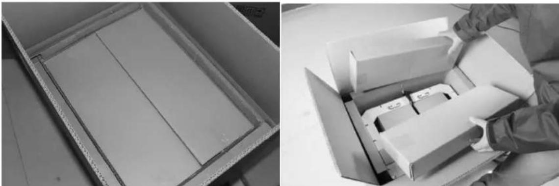
First, place the box on the oor in a clean and at surface. Remove the top carton and pull out the cardboard packing that encloses the Creator.
natural_image
Two black-and-white photos: one showing a cardboard box with internal compartments, the other showing a close-up of stacked boxes with a hand adjusting it (no visible text or symbols)You can see the top of the printer along with more boxes inside. The large box with the black wire is the accessory box. This contains the extruder(s), SD card, and other important components. Do not remove the accessory box and its contents yet. Note: Do not li the box by the black cable. Doing so could cause damage.
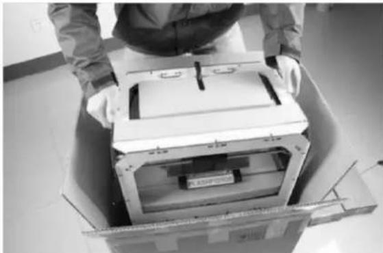
Next, take the Creator out of the box by grasping the outer frame. Be sure to grasp only the frame. Gently li and transfer the printer to your work surface, as shown on the next page.
natural_image
Person assembling a large electronic device into a cardboard box (no visible text or symbols)With the Creator removed, you will nd the power supply and cable, USB A to B cable, and a lament guide tube. Remove them from the box and set them aside. Now, open the accessory box and remove the accessory sleeve.
natural_image
Two-panel black-and-white photo showing a person handling equipment in a lab setting, no visible text or symbols.You will nd the extruder in the protecve packaging along the black cable. Carefully remove it and place it on your work surface. Remove the cardboard packing material and take the accessory box from the printer; set it aside for later.
The build plaorm should now be visible. It is an aluminum plate covered in a thin polyamide Im. This is the surface that your objects will be printed on. Note: Remember not to remove this Im. The next step is to raise the build plaorm. There are two ways to do this:
-
Turn the screw that is behind the rotang plaorm.
-
Grasp the prinng plaorm with one hand on each side, raising it slowly and keeping it level. Stop once the plaorm is just shy of the bronze nozzle.
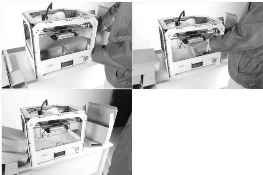
natural_image
3D printer internal structure with visible paper and casing, no text or symbols presentNext, you should be able to see underneath the build plaorm. Here, you'll nd the lament (either one or two rolls depending on whether your Creator has single or dual extruders). It's easiest to remove the lament by seng aside the remaining packaging material.
To do this, remove the long box in the front, then the small box on the right, and nally the two wire trays. You have now nished unboxing! The next task is to setup the hardware.
natural_image
Black-and-white photo collage showing three views of a 3D printer with open lid, being handled by gloved hands (no visible text or symbols)3
Inial Hardware Installaon

WARNING:
Prior to powering on the Creator, make sure the power supply switch is set to 115v if you are located in the United States. For other countries, please refer to your country standards. Failure to do so will damage the motherboard.
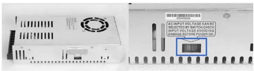
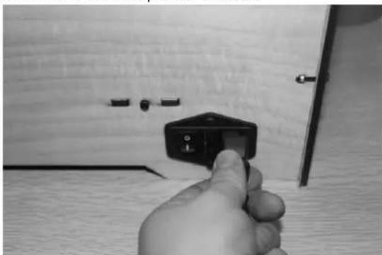
Prior to installaon, please make sure that the red power supply switch at the boom of the Creator is set to 115V (for United States).
To do this, begin by carefully placing the Creator on one of its sides so that the boom is exposed. You will see the Creator's power supply. Using a athead screwdriver, switch the red power supply switch so that it displays 115V, as shown below. Now you are ready to install the extruder.
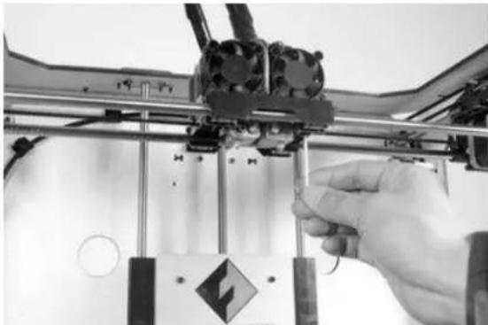
You'll need two silver screws from the bolt tool plate found in the accessory box and the appropriate hex wrench.
First, lower the build plaorm using one of the methods described in the previous secon. Holding the extruder by both sides, take it out of the accessory sleeve and posion it on the extruder seat with the fan facing forward. Align the screw holes and fasten with the shortest silver screws.
natural_image
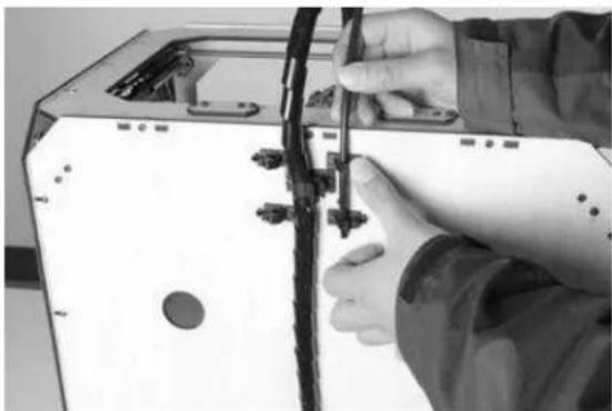
Close-up of a hand operating a 3D printer with visible mechanical components and a warning symbol (no text or labels)Next is the installaon of the lament bracket. If you have two brackets, install one on each side; If you only have one, install it on the right hand side (when viewing the creator from the front).
The installaon of the lament bracket is very simple – just insert it into the circular opening and ghten the nut behind. Then, install the lament guide tube to the empty spot on the extruder. Place one end of the guide tube into the hole.
natural_image
Close-up of hands installing or adjusting a cable on a device (no visible text or symbols)The hardware installaon is almost complete.
Next, with the power switch in the 'OFF' posion, conrm that the power cord is plugged into the power outlet next to the power switch.
natural_image
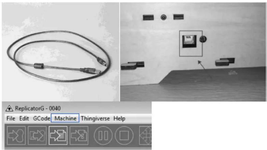
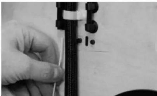
Hand inserting a small black component into a wooden wall, no text or symbols visibleNow plug the USB A to B cable into the USB B-type port, do not plug the other end in yet.
Finally, take the lament out of the box, install it onto the bracket and screw in the nut. Do not over ghten.
Congratulations! You have completed the initial hardware installaon! If you're ready to start prinng, proceed to the next step: Soware Installaon.
4
Soware Installaon
ReplicatorG0040 is the ideal soware to use with the single or dual extruder Creator. The latest version can be downloaded from our ocial website by following the link below and clicking on "Download Replicator G 0400 Installer".
hp://www.ashforge-usa.com/printer-support/downloads/
Download the les suitable for your system and decompress/extract them. For this guide, we will be installing on a Windows PC. For Mac users, please e-mail FlashForge USA at supports@ashforge-usa.com if you encounter any problems or setbacks throughout this guide.
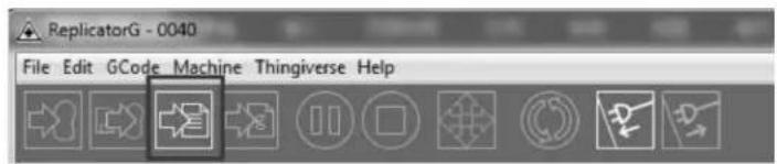
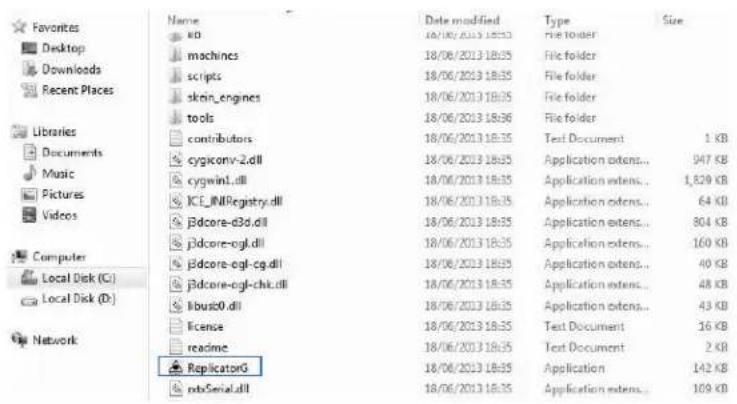
Run the Python installaon le and the Python acceleraon components. Click Replicator-0040-Installer to install the Replicator G soware. To run the Replicator G soware, double click on the ReplicatorG icon highlighted below.
![ReplicatorG - 0040 File Edit GCode Machine Thingiverse Help Not Connected Untitled: gcode [11:35:15] C:\Users\Beazer\Desktop\20mm_cube.stl [11:35:15] Couldn't find a port to use!](/content/2026/05/1058994/images/d57138d43d7b5fccf5e1185f9df3a02942b29a3cbeab1b71e75dde9e50e374cd.jpg)
Aer opening Replicator G soware, click on Machine to select your Machine Type. Choose The Replicator Dual for Creator dual extruder machines, and choose The Replicator Single for Creator II single extruder machines. In this guide, we will select The Replicator Dual.
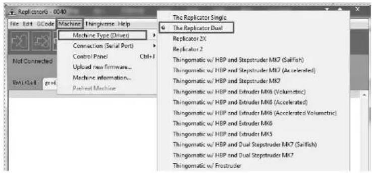
Aer selecng the appropriate machine, click on GCode on the top navigaon bar, and under GCode Generator, select Skeinforge (50).
The following gives an introducon on how to import les (.STL) into the Replicator G soware and generate Gcode in order to print.
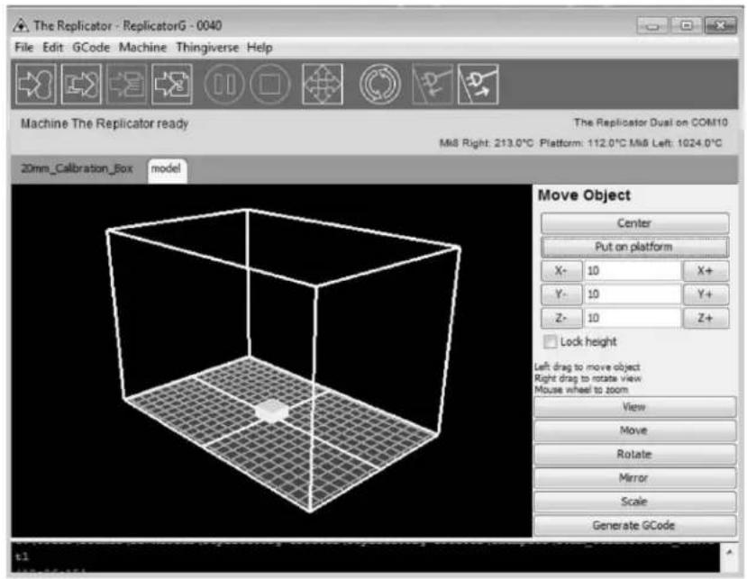
Click File > Open, then browse and select the le (.STL) that you would like to print. Import the le by double-clicking on it. The drawing design will appear on the Replicator G interface.
![ReplicatorG - 0040 File Edit OCode Machine Thingiverse Help Not Connected 20mm_cube model Preview Default XY XZ YZ Drag to rotate Moves wheel to zoom View Move Rotate Mirror Scale Generate OCode [11:20,10] C:\Users\Beaser\Desktop\20mm_cube.stl [11:22,15] Couldn't find a port to use [11:26,97] Loading C:\Users\Beaser\Desktop\20mm_cube.stl [11:20,07] C:\Users\Beaser\Desktop\20mm_cube.stl](/content/2026/05/1058994/images/689c6a349e26b55d29070394ebe38bdce740806f4be08fa4130645aec2a262e0.jpg)
When the object is imported, you may nd that it is not on the virtual build plaorm or even on the screen. Using the funcon keys indicated by the blue boxes in the illustraon above, you can change the camera angle and reposion the object onto the center of the build plaorm. Once you've done this, the next step is to generate the Gcode. This is achieved by clicking on the Generate GCode at the boom of the panel.
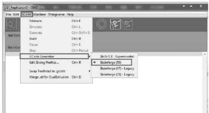
A new window will open up, giving you several opons on how the Gcode will be generated:
A. Slicing Prole: select Replicator slicing defaults for ABS prinng, then select Replicator 2 slicing defaults for PLA prinng.
B. This tells the printer which extruder to use for a dual extruder-headed printer — either the left head or the right head can be selected.
C. If your sample will have any hanging surfaces, it is recommended to have support. Selecting 'None' indicates that there is no support; "Exterior" means surface support; and 'Full Support' means all support.
D. Object inll: where 100% is a solid print, 0% is a hollow object. The recommended seng is 10%; this will save me and lament.
E. Layer Height: this controls the vercal resolution of the print. The recommended thickness is 0.27mm.
F. Number of Shells: this is the wall thickness; it's usually set at 1.
G. Feedrate: this is the speed at which the lament is fed into the extruder. This is usually set between 30 and 70 ~mm / s . For ABS prinng, 60 ~mm / s is recommended; for PLA prinng, 100 mm/s is recommended.
H. Travel Feedrate: this is the speed at which the printer head moves over the base, it's usually set between 30 and 100. For ABS prinng, 80 is recommended, for PLA prinng, 120 is recommended.
I. Print Temperature: this is the temperature at which the nozzle is heated. This varies between lament types. Set it to 220 for the default lament.
Aer you are nished inpung in the sengs, click Generate Gcode, and the progress bar will appear.
For users who did not choose the default installaon path in the installaon of Python, clicking the Generate Gcode buon in Replicator G will result in dialogue box popping up alerng that the executable Python le cannot be found.
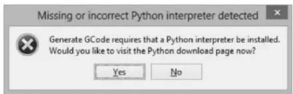
In order to resolve this, click the 'No' buon to dismiss the dialogue box. Next, we need to conjure the corresponding menu.
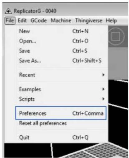
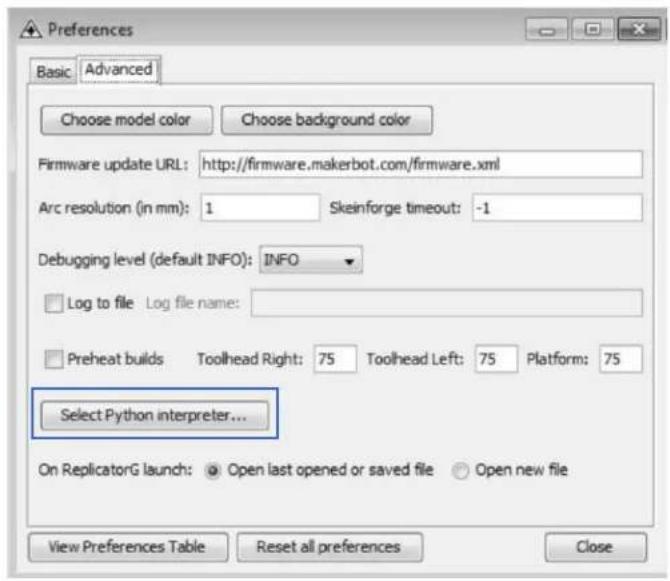
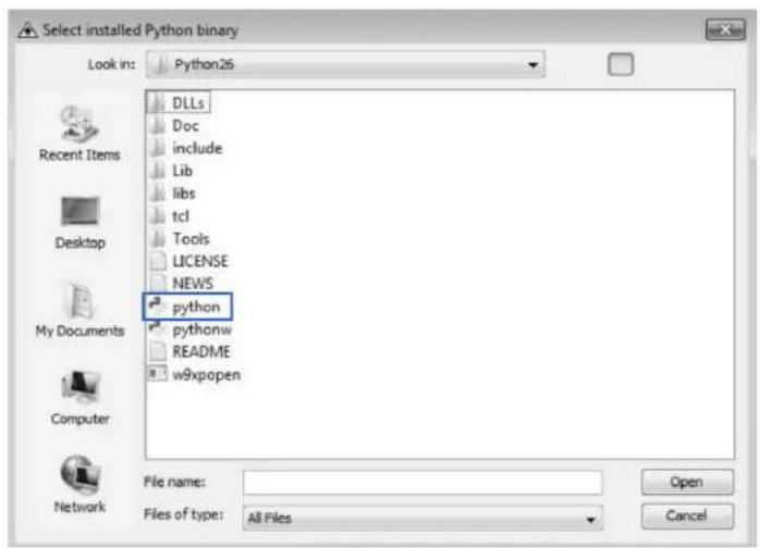
Click File > Preferences on the top navigaon bar, then click Select Python Interpreter under the Advanced tab. A new window will pop up. Navigate to the Python installaon directory and select python.exe and click 'Open'.
Last, click 'Close' on the Preferences menu and you are done!
The machine will now work as normal when generang Gcode, and the Python error message will not pop up again. In the next secon, we will start a preliminary test on the machine's connnecons and heat the plaorm so that the extruder is ready for its rst print!
5 USB Connecon & Temperature Seng
First, connect the machine and the computer using the provided USB A to B cable. The USB port on the machine is bound by the box in the below image. Aer connecng the cable, open the Replicator G soware as we are going to link the computer and printer.
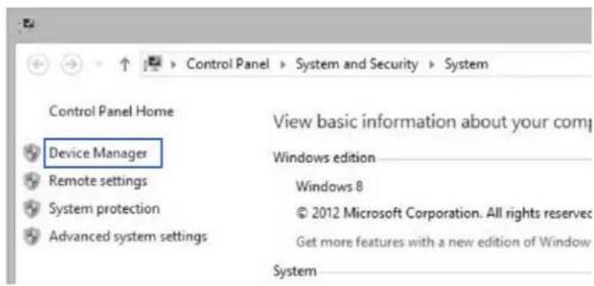
Inside the Replicator G soware, click Machine > Connecon (serial port) > Rescan serial ports, if no new ports appear, then the soware driver has not been installed. To install the driver manually, go to 'My Computer' and right click on 'Properes'. The basic system parameters appear. Next, select 'Device Manager'.
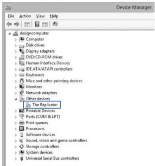
Locate the soware driver shown in the blue box above. Right click and select 'Update Driver Soware'.
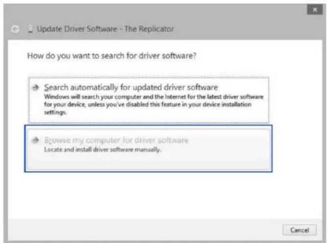
Click 'Browse my computer for driver soware' to nd the locaon of ReplicatorG0040 on your system.
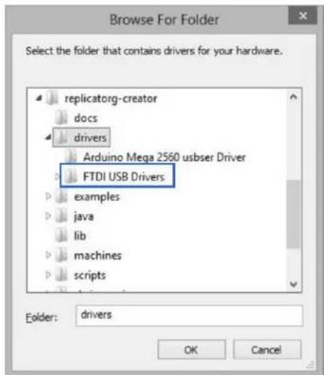
Click 'FTDI USB Drivers' in the driver folder and click 'OK'. The drivers will then be installed.
The next step is to link the printer. Rescan the serial ports and select the one that appears on your machine (on our test machine the port was COM10).
![ReplicatorG - 0040 File Edit GCode Machine Thingiverse Help Machine Type (Driver) Connection (Serial Port) Control Panel Ctrl+J Upload new firmware... Machine information... Preheat Machine COM10 Rescan serial ports Not Connected 20mm_cube mo Preview Default XY XZ YZ Drag to rotate Mouse wheel to zoom View Move Rotate Mirror Scale Generate GCode [11:43:81] File C:\Users\Beamer\Desktop\20mm_cube.stl is being chain exported. [11:43:54] Carve procedure took 2 seconds. [11:43:59] Preface procedure took 6 seconds. [11:80:46] 20600 bytes written to C:\Users\Beamer_.replicatorg\firmware.xml](/content/2026/05/1058994/images/fbd80dd19d8107dae721776e61d3d8f5db86da9ced76233ca95ee3f26e4e8b04.jpg)
Now we can link the machine to the computer. Click on the printer connect icon highlighted in blue.
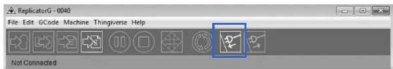
If the printer connect icon turns dim, as shown in the illustraon below, the printer has successfully connected to the computer. Next, we need to preheat the extruder and build plaorm.
![The Replicator - ReplicatorG - 0040 File Edit GCode Machine Thingiverse Help Machine The Replicator ready The Replicator Dual on COM10 M68 Right: 24.0°C Platform: 15.0°C M68 Left: 1024.0°C 20mm_cube model code Preview Default XY XZ YZ Drag to rotate Mouse wheel to zoom View Move Rotate Mirror Scale Generate GCode [12:09:09] Connecting to machine using serial port: COM10 [12:09:11] Motherboard firmware v7.2 ( ) [12:09:11] Tool Count Hissmatic. Repeating 2 tools, reported 1 tools [12:09:11] Please double-check your selected machine.](/content/2026/05/1058994/images/bd9c34443a53fe270c3a6e5ba9056c1fd93acb04fd89ef494e53658502efb098.jpg)
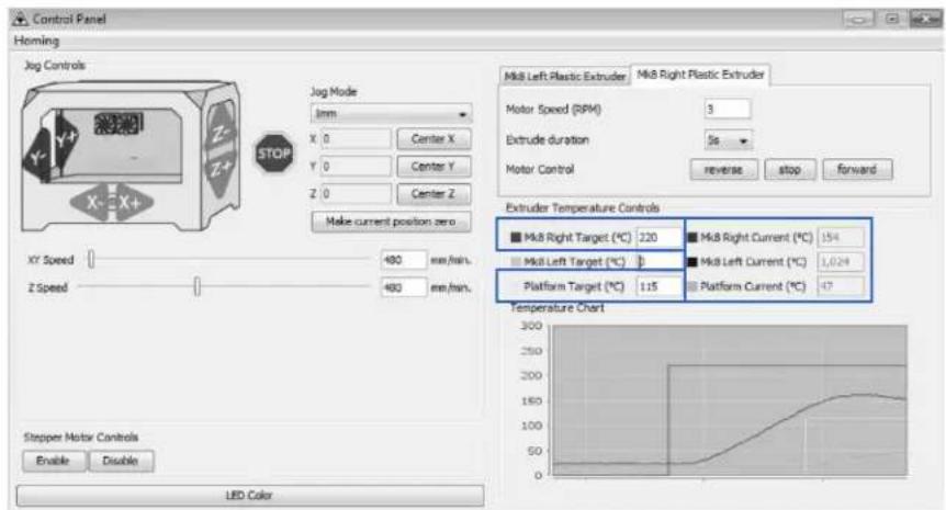
In the same set of menu, click on the cross-shaped icon and a new interface will appear.

Input the following target values: 220°C for the extruder and 115°C for the heang plaorm. Aer entering the values, the plaorm will start to warm up. When the extruder temperature reaches 50°C, the cooling fan will acvate and the current temperature value will display to the right as shown on the following page.
6
Filament
To make the process of feeding the lament into the printer easy, please follow the next few steps carefully:
Aer inserng the lament into the feeding hole, do not push it further until the extruder temperature reaches 200^ C or more. Once the machine reaches this point, you will feel the lament being pulled into the extruder head.
6.1 Installing the Filament
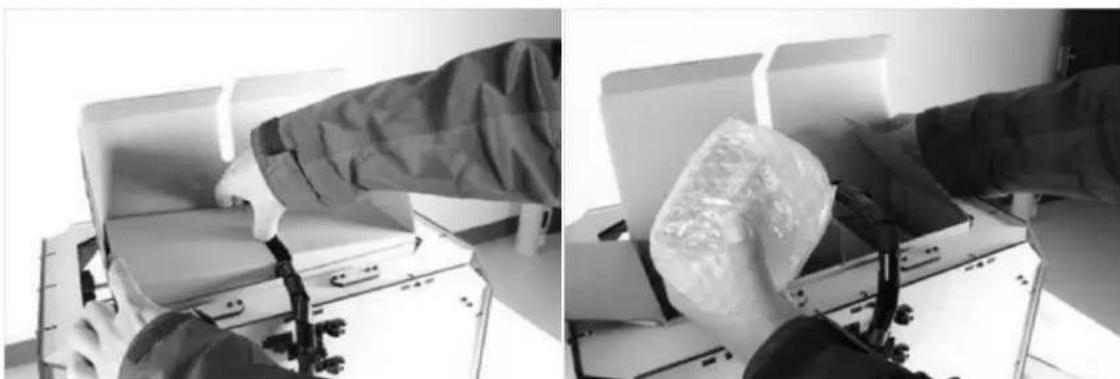
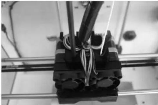
First, remove the lament guide tube from the extruder head.
natural_image
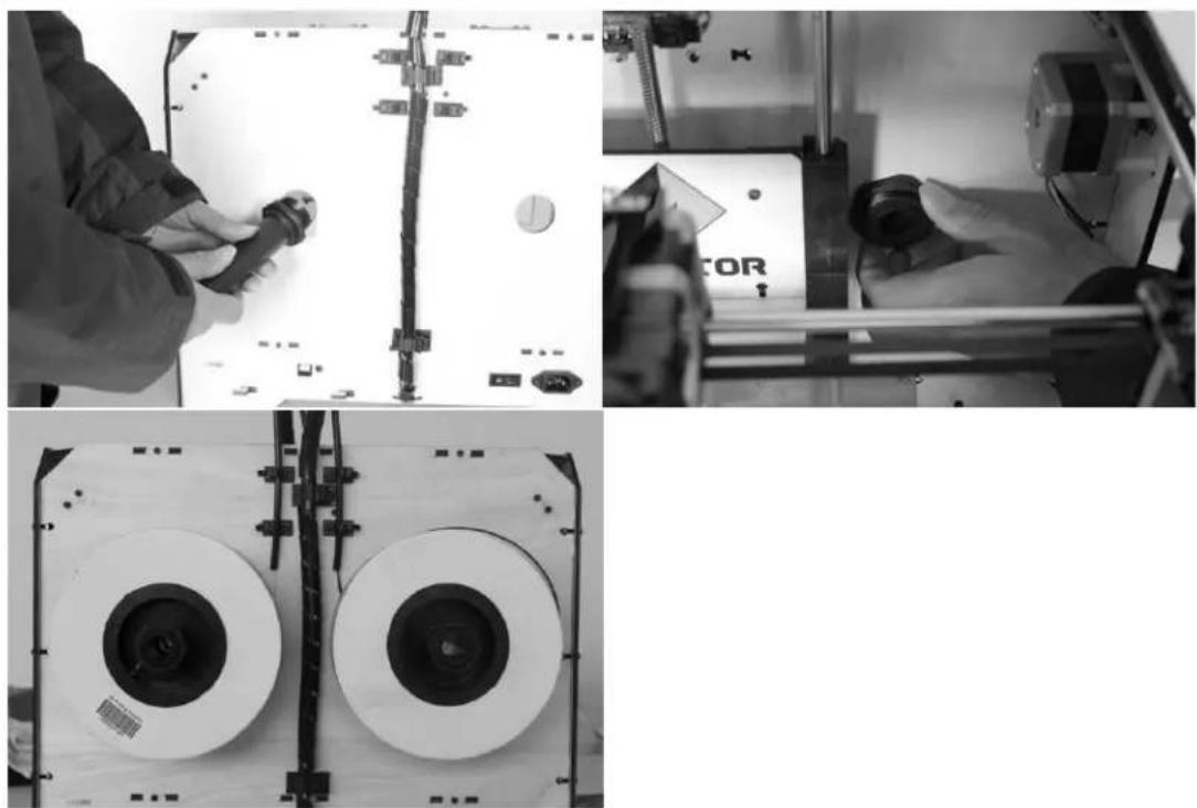
Close-up of a mechanical assembly with coiled wires and metal frame (no visible text or symbols)When you have removed the guide tube, you can remove the lament that is inside the guide tube. To avoid any blockages during prinng, please ensure that the two threads are loaded from the middle. There are two wire trays, one runs clockwise and the other one runs counter-clockwise, as shown below:
natural_image
Close-up of a hand holding a thin wire next to a black mechanical component (no visible text or symbols)6.2 Feeding the Filament Using LCD Screen
- Turn on the Creator; the display will indicate:
▶ Build from SD Preheat Ulies
- Using the direconal arrows to the right of the screen, press the page down key to scroll to the next page. The display will show:
Preheat
▶ Ulies Info and Sengs
- Select Ulies; press the middle key in the middle of the keypad. The display will show:
Monitor Mode
▶ Change Filament
Level Build Plate Home Axes
Feed operaon with LCD screen
- Select Change Filament; press the middle key in the middle of the keypad. The display will show:
▶ Load Right Unload Right Load Le Unload Le
- Select the appropriate side of the extruder you wish to load (Le or Right for models with dual extruders). Press the middle key again on the keypad. The display will indicate: "I'm heang up my extruder!" At this me, the temperature of the nozzle is being heated up. When the temperature of the nozzle reaches its target temperature, press the middle key on the keypad, and the nozzle should start extruding material. If not, keep pressing the middle key unl it does.
6.3 Withdrawing the Filament Using LCD Screen
The procedure to remove lament from the extruder is simple. We will rst load the lament so that it can extrude the material. Aerwards, we will unload the lament and remove it from the extruder. This is so that the removal process is smooth and the lament does not become stuck.
- Turn on the Creator; the display will indicate:
▶ Build from SD Preheat Ulies
- Using the direconal arrows to the right of the screen, press the page down key to scroll to the next page. The display will show:
Preheat ▶ Ulies Info and Sengs
- Select Ulies; press the middle key in the middle of the keypad. The display will show:
Monitor Mode ▶ Change Filament Level Build Plate Home Axes Feed operaon with LCD screen
- Select Change Filament; press the middle key in the middle of the keypad. The display will show:
▶ Load Right Unload Right Load Le Unload Le
-
Select the appropriate side of the extruder you wish to load (Le or Right for models with dual extruders). Press the middle key again on the keypad. The display will indicate: "I'm heang up my extruder!" At this me, the temperature of the nozzle is being heated up. When the temperature of the nozzle reaches its target temperature, press the middle key on the keypad, and the nozzle should start extruding material. If not, keep pressing the middle key until it does. Allow the FlashForge Creator to extrude material for approximately 10 seconds, and proceed to the next step.
-
Select Exit to go back to the previous menu. Using the keypad, select Unload (Side), depending on which extruder you wish to remove lament from (for dual extruder model only). The Creator will now begin to heat up again to its target temperature.
-
After it is nished heang up, the extruder will begin to reverse its gears and unload the lament. Assist in the removal process by pulling the lament out very gently, making sure the angle of the lament is straight up and not crooked. Failure to do so may cause the removal process to fail.
In the event that a grinding noise occurs and the lament stop unloading, select Exit on the LCD screen and repeat steps 1 to 6. If the error persists aer several aempts, please call FlashForge USA technical support at 626-322-3855 (M-F 8:30 a.m. PST – 5:00 p.m PST) or e-mail supports@ashforge-usa.com.
6.5 Seng the Parameters
Before generating Gcode, specific parameters can be set up to customize various aspects of the print. An explanaon to each of the settings can be found in the previous secon (pages 13-14).
7 Inial Print
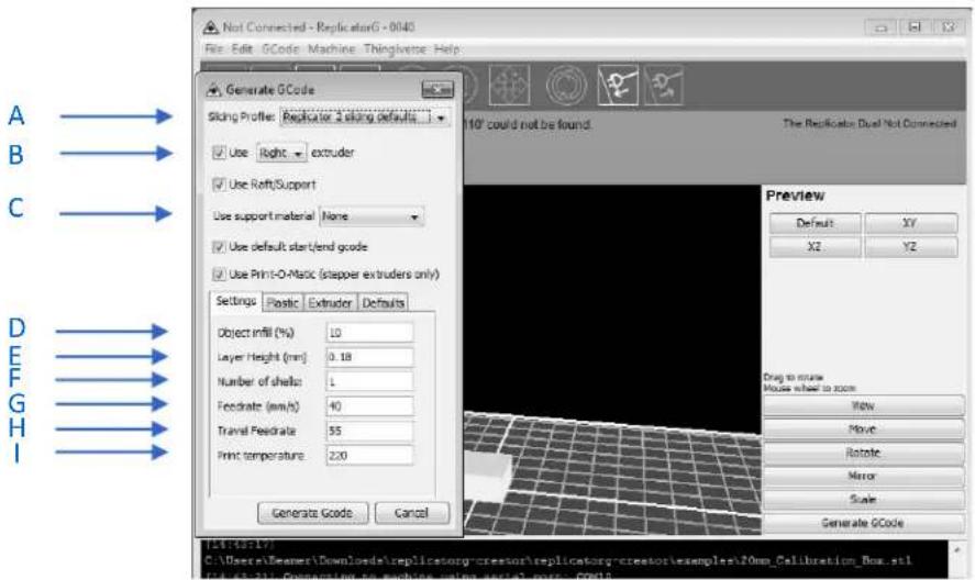
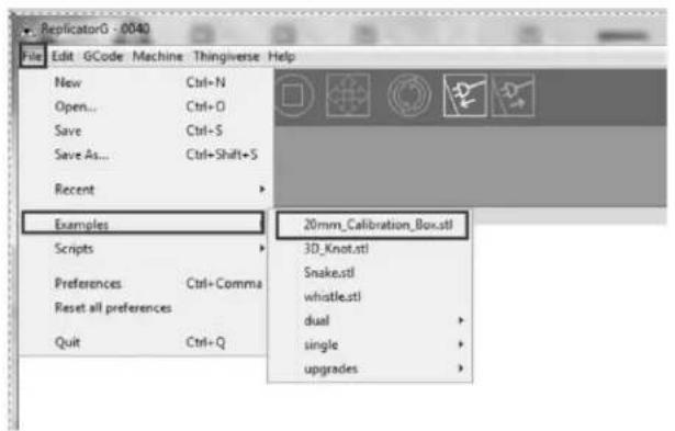
Click File > Examples and then select "20mm_Calibraon_Box.stl". The preview interface will then appear along with a virtual impression of the 20mm cube on the virtual printer bed. On the preview interface click Move > Center and Put on plaorm so that the sample will be printed on the center of the build plate.
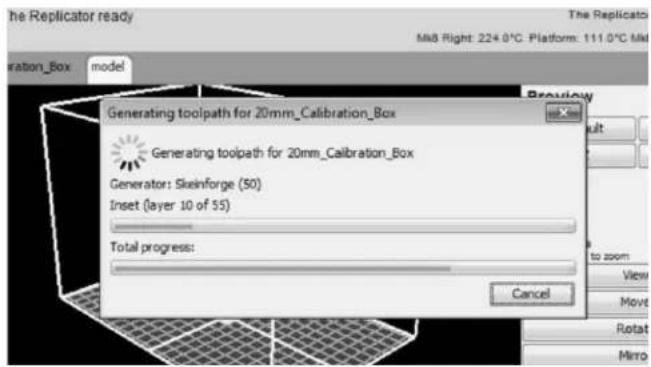
Next, click Generate GCode; a dialogue box will pop up. Aer inpung your chosen parameters, the Gcode will be generated.
![The Replicator - ReplicatorG - 0040 File Edit GCode Machine Thingiverse Help Generate GCode Slicing Profile: Replicator 2 slicing defaults Use Right - extruder Use Raft/Support Use support material None Use default start/end gcode Use Print-O-Matic (stepper extruders only) Settings Plastic Extruder Defaults Object infill (%) 10 Layer Height (mm) 0.18 Number of shells: 1 Feedrate (mm/s) 40 Travel Feedrate 55 Print temperature 220 [12:26:15] C:\Users\Beamer\Downlost [12:29:10] gcode source replicator.gpp.gcode.bhasableGCodeSource@a20099 The Replicator Dual on COM10 M8 Right: 214.0°C Platform: 111.0°C Mk8 Left: 1024.0°C Preview Default XY XZ YZ Drag to rotate Mouse wheel to zoom View Move Rotate Mirror Scale Generate GCode Generate Gcode Cancel Generator\examples\20mm_Calibration_Box.s](/content/2026/05/1058994/images/7fc055a5821d2cc90af6e112dfe43adc5515e2c7ad94358d1b0f4c142121db8d.jpg)
A loading bar will then appear showing the progress of the Gcode generaon.
Aer the Gcode is generated, the temperature of the boom plate needs to be changed. See below for the required modicaon. First, select Gcode as shown highlighted in the illustraon below and change 'M109 S110 T0' to 'M109 S115 T0'.
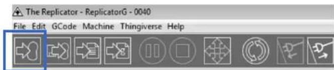
Aer modifying, click on le and save the sample. Next, click on the le most icon on the green bar, as highlighted below. The Gcode has now been sent to the printer and the object will start prinng shortly.

Dual Extruder Print
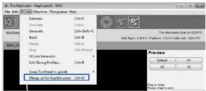
Open Replicator G and select Gcode > Merge.stl for Dual Extrusion. You will see the following:
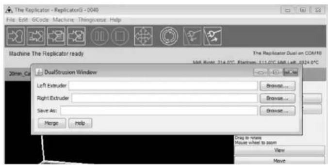
Click on the rst Browse buon to locate and select the le for the le extruder, and then click on the second Browse buon for right extruder:
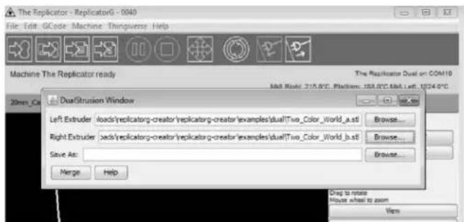
Click on the third Browse buon to save these two les as one .gcode le on the desktop; now click Merge buon, you will see two dialogue boxes pop up:
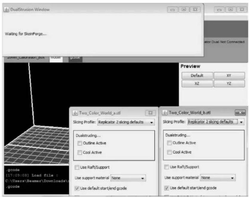
If you want to print dual colors with PLA lament, then perform the following sengs:
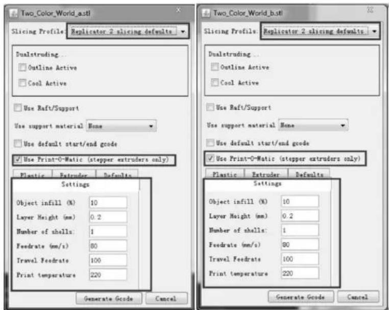
If you want to print dual colors with ABS lament, select Replicator slicing defaults under the Slicing Prole column, and lower the Feedrate to 60 and Travel Feedrate to 80.
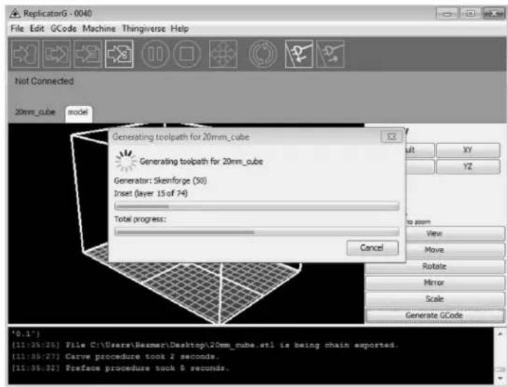
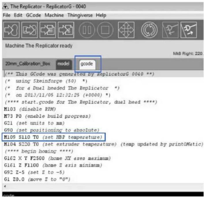
Click the Generate Gcode opon for both boxes. Aer the Gcode is generated, click on the gcode tab as highlighted below and change HBP temperature to 50 if you are prinng with PLA and save this modicaon by going to File > Save.
![The Replicator - ReplicatorG - 0040 File Edit GCode Machine Thingiverse Help Machine The Replicator ready 20mm_Calibration_Box model gcode [** This GCode was generated by replicatorG 004 (* using Skeinforge (50) *) (* for a Dual headed The Replicator *) (* on 2013/11/05 12:32:25 (+0000) *) (***** start.gcode for The Replicator, dual head M103 (disable RPM) M73 P0 (enable build progress) G21 (set units to mm) G90 (set positioning to absolute) M105 S110 T0 (set HBP temperature) M104 S220 T0 (set extruder temperature) (temp u (***** begin boring ****) G162 X Y F2500 (home XY axes maximum) G161 Z F1100 (home Z axis minimum) G92 Z-5 (set Z to -5) C:\Users\Beamer\Downloads\replicatory-creator\re b.stl is being chain exported. [12:57:59] SteinForge returned FAILURE - Abortin [12:58:59] SteinForge returned FAILURE - Abortin](/content/2026/05/1058994/images/349ac14ddf9f6cad0d7b0922f6d5ca01160bd0f40edfc28474e600d526d01fe0.jpg)
Click on the following buon to export .x3g le for SD card print.