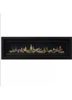
Element 1200 MK2 - Heating Real Flame - Free user manual and instructions
Find the device manual for free Element 1200 MK2 Real Flame in PDF.


| Product Type | Electric Fireplace Heater |
| Brand | Real Flame |
| Model | Element 1200 MK2 |
| Width | 1200 mm (47.2 in) |
| Height | 600 mm (23.6 in) |
| Depth | 250 mm (9.8 in) |
| Weight | 25 kg (55 lbs) |
| Power Supply | 220-240V AC, 50Hz |
| Power Consumption | 1500W (max) |
| Heat Output | 5100 BTU/h |
| Heating Method | Fan-forced convection |
| Heating Area | Up to 400 sq ft (37 m²) |
| Flame Effect | Yes, with adjustable brightness and color |
| Thermostat | Adjustable (16-28°C) |
| Remote Control | Included |
| Safety Features | Overheat protection, tip-over switch, cool-touch glass |
| Installation | Freestanding or wall-mounted (bracket included) |
| Material | Steel and tempered glass |
| Color | Black |
| Cleaning | Wipe with soft dry cloth; do not use water or solvents |
| Maintenance | Check power cord regularly; replace light bulbs as per manual |
| Spare Parts | Available from Real Flame customer service |
| Repairability | Repairs by qualified technician; use only genuine parts |
| Certifications | CE, UKCA |
| Warranty | 2 years |
Frequently Asked Questions - Element 1200 MK2 Real Flame
User questions about Element 1200 MK2 Real Flame
0 question about this device. Answer the ones you know or ask your own.
Ask a new question about this device
Download the instructions for your Heating in PDF format for free! Find your manual Element 1200 MK2 - Real Flame and take your electronic device back in hand. On this page are published all the documents necessary for the use of your device. Element 1200 MK2 by Real Flame.
USER MANUAL Element 1200 MK2 Real Flame
ELEMENT 1200 MARK 2 & 1800 MARK 2 SPACE HEATERS ALL FLUE CONFIGURATIONS
INSTALLATION AND OPERATIONS MANUAL

natural_image
Technical line drawing of a ductwork pipe system mounted on a rectangular base (no text or symbols)The Real Flame Element space heater is suitable to be installed into a frame out installation. Designed to operate on Natural gas, LPG and ULPG
Approval no. GMK 10441
Consumer safety information: please read this manual before installing and operating this appliance. Failure to follow these instructions may result in a possible fire hazard and/or injury and will void the warranty.
CONTENTS
WELCOME 3
SPECIFICATIONS 4
OPERATION INSTRUCTIONS
USER INSTRUCTIONS 7
WiFi DEVICE CONTROL INSTRUCTIONS TROUBLESHOOTING FOR YOUR FIREPLACE
INSTALLATION INSTRUCTIONS
UNIT DIMENSIONS 21
MINIMUM FRAMEOUT DIMENSIONS 22
TRIM DIMENSIONS 23
INSTALLING ELECTRIC EQUIPMENT ABOVE FIREPLACE 25
INTERNAL FAN AND ROOF TERMINATION
ROOFTOP TERMINATION WITH EXTERNAL MOTOR
5-10M INSULATED FLUE CONFIGURATION
INSTALLATION INSTRUCTIONS 50
EXTERNAL WALL MOUNTED FAN MODULE INSTALLATION 54
INTERNAL FAN AND WALL TERMINATION INSTALLATION 58
INTERNAL FAN AND ROOF TERMINATION
ROOFTOP TERMINATION WITH EXTERNAL MOTOR
10-13.5M POLYPROPYLENE FLUE CONFIGURATION
INSTALLATION INSTRUCTIONS 78
SETUP WITH EXTERNAL WALL MOUNTED FAN TERMINAL 82
INTERNAL FAN AND WALL TERMINATION INSTALLATION 90
10-13.5M ROOFTOP POLYPROPYLENE FLUE CONFIGURATION
INSTALLATION INSTRUCTIONS 99
SETUP WITH INLINE OR APPLIANCE MOUNTED FAN 103
COMMISSIONING PROCEDURE 109
MEDIA INSTALLATION 110
CONVERSION DETAILS 115
PARTS LIST 122
APPENDIX 1- FLUE TERMINATION
APPENDIX 2-WIRING DIAGRAMS
WARRANTY INFORMATION 125
WELCOME
Congratulations on your selection of the elegant Real Flame Element MK2 Fireplace. Enjoy mesmerising flame patterns in a truly efficient gas fireplace. The Element Range is simply breathtaking with its clean lines, beautiful flame pattern and multiple media options. We hope you create endless memories in front of this warm and cosy fireplace.
Read this manual before attempting to install or use the fireplace. Always comply with the warnings and safety instructions contained in this manual to prevent injury or property damage. When using the fireplace basic precautions should always be followed to reduce the risk of fire and injury.
INSTALLATION NOTICE
The installation of this appliance is only to be carried out by an authorised person in accordance with the Manufacturer's Instructions, local gas fitting regulations, AS/NZS5601.1-2013 installation code for gas burning appliances and any other relevant statutory regulations.
In all cases the installation of this appliance shall meet the requirements as set out in AS/NZS5601.1-2013.
Do not install in a fireplace as a Type 1 installation. Not intended as a fireplace insert.
NOTE: A slight smell may be apparent for the first few hours of use. This is due to the heat resistant paint curing. It is recommended to open windows in the room for the first lighting of the fire. In some instances a slight discolouration may occur inside the firebox. This is a normal condition and is not covered by warranty.
WARNING
The Element space heater has a primary safety glass fitted in front of the glass door. This safety glass is fitted to this appliance to reduce the risk of injury from burns and at no time should this glass be permanently removed.
For protection of young children or the infirm, a secondary guard is required.
The appliance is not intended for use by persons (including children) with reduced physical, sensory or mental capabilities, or lack of experience and knowledge, unless they have been given supervision or instruction concerning use of the appliance by a person responsible for their safety. Children should be supervised to ensure that they do not play with the appliance. The glass panel gets extremely hot! Precaution should be taken
and young children supervised at all times when the heater is operating.
IMPORTANT SAFETY NOTICE
Do not place articles on or against this appliance.
Do not use or store flammable materials in or near this appliance.
Do not spray aerosols in the vicinity of this appliance whilst it is in operation.
Care must be taken to ensure that any return air register or exhaust system does not adversely affect the operation of the appliance or draught of chimney or flue.
Do not modify this appliance.
Appliance is designed to operate with luminous flames. May exhibit slight carbon deposit.
SERVICING
It is recommended you service your gas fire every 2 years as a minimum.
CORD REPLACEMENT
Electrical cord replacement must be undertaken by qualified and trained personnel only.
SPECIFICATIONS OF ELEMENT 1200 MK2
| Appliance Type | High Efficiency Gas Fireplace | ||
| Star Rating | Up to 4.8 stars | ||
| Maximum Heating Output | Up to 8.7kW | ||
| Heats Room up to | 105m2 approx. | ||
| Gas Type Natural Gas LPG ULPG | |||
| Gas Input | 37 High/29 Low 33 | High/27 Low 30 High/25 Low | |
| Operating Pressure (TPP) | 0.85kPa High / 0.55kPa Low | 2.50kPa High / 1.70kPa Low | 2.55kPa High / 1.70kPa Low |
| Max - Min Inlet Pressure Range | 1.13kPa - 5.00kPa 2 | 75kPa - 5.00kPa 2.7 | 5kPa - 5.00kPa |
| Injector Size | 3 X 2.25mm 3 X 0.95 | mm 3 X 0.90mm | |
Aeration Settings
| Media Setup | Natural Gas LPG | ULPG |
| Driftwood | 5.0 | 10.0 Not Available |
| Coals and Logs | 5.0 | 10.0 Full open |
| Pebbles | 5.0 | 10.0 Full open |
| Redgum and Coals | 5.0 | 10.0 Full Open |
* Subject to model and flue configuration
SPECIFICATIONS OF ELEMENT 1800 MK2
| Appliance Type | High Efficiency Gas Fireplace | ||
| Star Rating | Up to 4.7 stars | ||
| Maximum Heating Output | Up to 9.1kW | ||
| Heats Room up to | 110m^2 approx. | ||
| Gas Type Natural Gas LPG ULPG | |||
| Gas Input | 39 High/30 Low | 39 High/30 Low | 33 High/27 Low |
| Operating Pressure (TPP) | 0.92 kPa High/0.55 kPa Low | 2.5 kPa High/1.70 kPa Low | 2.50kPa High/1.70 kPa Low |
| Max - Min Inlet Pressure Range | 1.13kPa - 5.00kPa | 2.75kPa -5.00kPa | 2.75kPa - 5.00kPa |
| Injector Size | 3 X 2.30mm | 3 X 1.05 | 3 X 0.95mm |
Aeration Settings
| Media Setup Natural Gas LPG ULPG | |||
| Driftwood | 4.5/4.5/2.0mmRH end | 10/10/10 | Not Available |
| Coals and Logs | 4.5/4.5/2.0mmRH end | 10/10/10 | Full open/Full open/Full Open |
| Pebbles | 4.5/4.5/2.0mmRH end | 10/10/10 | Full open/Full open/Full Open |
| Redgum and Coals | 4.5/4.5/2.0mmRH end | 10/10/10 | Full open/Full open/Full Open |
* Subject to model and flue configuration

OPERATION INSTRUCTIONS

USER INSTRUCTIONS
- Do not operate if you smell gas. Turn appliance off, extinguish any open flame. Contact your installer or a licensed gasfitter.
- Do not use if any part of this appliance has been submerged in water. Contact your installer or a qualified service technician.
- Solid fuels must not be burnt in the fire. Leaves, sticks, wood, paper food or material must be kept away from the fire.
- Should the appliance fail to ignite or was recently turned off, allow 5 minutes before attempting to reignite appliance. In the event of abnormal operation please contact your licensed gas installer, gas service personnel or Glen Dimplex Pty Ltd. Abnormal operation may consist of the following, noisy fan, excessive or small flame, unusual flame appearance or colour, excessive sooting or other.
- Press power button ⏻ on the remote.
- Press mode button until manual appears on lower area of screen
- Press arrow up or down to change temperature.
- Set the desired temperature - it must be above the room temperature for the appliance to operate.
- Appliance will start once the flame symbol appears on the remote.
- Appliance will perform a 40 second pre-purge, then sparking will occur.
- Fire should operate within 1 minute of remote calling for heat.
NOTE - Should the fire not start, a post purge may occur, turn off remote - wait 5 minutes before reattempting to light the fire.
NOTE – The Element MK2 is fitted with a gas pressure switch, in the event of no gas, gas supply turned off or low gas pressure the appliance will not operate.
REMOTE CONTROL GUIDE
The Element MK2 heater is controlled completely by the use of the remote control; this remote can be used either as a manual operation or an auto operation.
- The remote thermostat uses radio frequency to transmit to the gas/fan controller.
• The remote thermostat has a LCD display. - The remote thermostat uses 2 off "AA" batteries which should last for 12 months. (Depending on quality of battery.) Batteries should be changed when smoke alarms are changed.
- The remote control and the controller are non-serviceable parts and if faulty should be returned to Glen Dimplex Pty Ltd for replacement.
LOCATING THE REMOTE
The remote houses the thermostat that controls the heat output of the fire. When storing the remote either on its wall bracket or by placing it somewhere in the room where the fire is located, ensure there are no other heat sources that will affect the thermostats ability to accurately read the room temperature. For example, by placing the remote in direct sunlight or under a cushion, the fire may turn down or off before the room reaches the set temperature.
Factory Set Features
- When turned on the fire will always start on the low setting and remain on low for 3 minutes, it will then go to the high setting.
-
The fan will automatically come on after the fire has been operating for 3 minutes 20 seconds.
-
When the fire shuts off on auto mode or is shut off in manual mode, the fan will continue to operate for up to 15 minutes.
- The fire can be operated in either 'AUTO' mode or 'MANUAL' mode.
REMOTE OPERATIONS
On/Off Press and release the thermostat on and off.

button to turn the
Setting the day of the week and time
With the thermostat off, press and hold the 'T' button for 2 seconds or longer to initiate programming the time. Time, the hour setting and AM/PM will flash.
Setting the hour function
Press and release ▲ the ▼ or button to increase decrease the hour setting by 1 hour. Press 'OK' to accept.
Setting the minute function
Press and release, ▲ press and hold the s or t button to increase or decrease the minute setting by 1 minute. Press 'OK' to accept.
Setting the day of the week function
Press and release the ▲ or button to change the day of the week to the following or previous day. Press and hold the ▲ ▼ button for 2 seconds or longer to increase or decrease the day of the week by 1 day every 0.5 seconds. Press 'OK' to complete setting.
Manual mode
Manual mode does not require that the time and day of the week are set. Press the ▲ or ▼ button to increase or decrease the temperature desired.
Automatic mode
The automatic mode allows the temperature to be regulated according to a programmed level and time. Manually overriding the set program At any time, the temperature may be adjusted up or down. However, whenever the thermostat changes to a new time period, the temperature will be set automatically according to that period's setting.
Programming
Each day of the week can be programmed individually for 4 periods P1, P2, P3 and P4, making a total of 28 programmed periods. Alternatively, a weekday program can be set, so the same program is used for Monday-Friday. Similarly, a weekend program can be set for Saturday-Sunday. The entire week can also have the same program.
Alternatively, a weekday or weekend program can be set with individual programs for the remaining days.
The suggested period settings for each day/s are:
Period 1 - morning
Period 2 - daytime
Period 3 - evening
Period 4 - night-time
To begin programming
With the thermostat off, press and hold the 'P' button for 2 seconds or longer to initiate programming. The LCD will display PROG, Pd and the time at which the thermostat is currently set. No will flash.
Period 1 can now be set.
Setting the day of the week
You must choose which day/s of the week you wish to program. Press and release the ▲ or ▼ button to change the day of the week to the following or previous day. Press and hold the ▲ or ▼ button for 2 seconds or longer to increase or decrease the day of the week by 1 day every 0.5 seconds.
The order that you can scroll through the days is as follows: MO → TU → WE → TH → FR → MO TU WE TH FR → SA → SU → SU → SA → MO TU WE TH FR SA SU
To accept the selected day/s of the week press 'OK'.
Setting the period starting time
The hour and AM/PM settings will now flash. To set the P1 starting time, press and release the ▲ or ▼ button to increase or decrease the hour setting. Press and hold the ▲r ▼button for 2 seconds or longer to increase or decrease the hour setting by 1 hour every 0.5 seconds.
Please ensure that AM/PM is set correctly.
Press 'OK' to accept.
The minute setting will now flash. Adjust the minute setting
similarly, using ▲or ▼button.
Press 'OK' to accept.
Setting the temperature
The temperature setting will now flash. Press and release the ▲ or ▼ button to increase or decrease the temperature setting by 1 °C. Press and hold the or button for 2 seconds or longer to increase or decrease the temperature setting by 1 °C every 0.5 seconds. Press 'OK' to accept.
Period 1 is now set for the day/s of the week that you have chosen. The LCD will display P2 to indicate that Period 2 can now be set for the same day/s of the week. Repeat the programming process for periods 3 and 4. After program 4 is set, press 'OK' and the program for the selected day/s will be set. Repeat the programming process for any other periods/days that are required.
Restore factory default settings
With the thermostat off, press the following sequence of buttons: 'P', 'T', 'T' ▼ .
Teaching RF thermostat ID code to control unit
CAUTION: The thermostat has already been programmed with a unique code. Do not attempt to teach the RF Thermostat ID code unless instructed by the manufacturer.
With the thermostat off, press the following sequence of buttons: 'P', 'T', 'T' ▲.
The LCD display will show 'CL' (Code Learn) for 2 seconds then return to the normal OFF state display. During this time a special code will be transmitted by the RF Thermostat to the Control Unit, causing the Control Unit to learn its ID.
WARNING
When the RF thermostat is in the "Auto" mode and the room temperature drops below the minimum temperature, the fire and fan will come on and operate until the room temperature is 3^ above the minimum and then turn off, therefore:
- The minimum temperature should be set at a temperature that is not likely to cause the fire to
continually turn on and off.
- If leaving the house for an extended period, the RF thermostat should be turned "OFF".
- As long as the RF thermostat is in the "Auto" mode and the temperature goes below the minimum set temperature, the fire will come on no matter what times are programmed into the thermostat.
- If you are unsure of the operation of the RF thermostat, please contact the manufacturer.
- In the event of loss of power, the appliance will shut down safely. The appliance may automatically resume operation once power is restored, pending the operation mode of the remote control.
Resetting the appliance from lockdown conditions
TECHRITE IGNITION MODELS
Should the appliance fail to operate and is in a lockdown condition
Turn remote to off
Turn mains power supply to appliance off for 10 seconds
Turn on mains power supply
Restart appliance with remote
Resetting the appliance from lockdown condition- SIT
IGNITION MODELS
Should the appliance fail to operate and is in a lockdown condition
Turn remote to off
Wait 5 seconds
Restart appliance with remote
WiFi DEVICE CONTROL INSTRUCTIONS
WiFi control is available on the Element MK2 range of space heaters. WiFi control offers a temperature feature which can be used in conjunction with the supplied remote control or as the independent control. Multiple devices can control the appliance. The appliance will operate based on its last received command.
Note 1 - Multiple devices may be connected to the appliance, only one appliance can be controlled by a device at a time.
Note 2 – The room air temperature sensing device is located in the remote, accuracy of the temperature sensing may be effected by the room layout, appliance installation and nearby furniture.
Note: The programming function is only done via the remote control.
Introduction
These pages outline the Operation of the Real Flame MKII Thermostat system. The System Includes
- Real Flame Modulating Valve MKII update
- Real Flame WiFi Interface MKII
- Real Flame Thermostat MKII App
- Real Flame MKII Web Service
These instructions assume that the Modulating valve has been installed into a fireplace with the WiFi module connected.
WiFi Set-up
From Factory settings the Fireplace will broadcast an Access Point for the Mobile App to join with, the Access point names have the following format, Realflame_XXXXXX
Where 'XXXXXX' is the last six digits of the WiFi modules MAC addresses, the Access point is secured with the default password 'realflame'
Joining the access point in this mode will allow you to,
- Control the Fireplace via its own WiFi Access point, and is good for Demo and testing functionality
- Push the Fireplace to a local or home network, this allows you to control the Fireplace whilst also being able to use your local network resource such as
Internet, email and Facebook.
- This mode is required to utilise the Server control features of the Fireplace.
INSTRUCTIONS FOR iOS DEVICES
Connecting to the fire through an access point
(eg: Phone or device directly connected to fire using phone or Device WiFi)
Step 1
Check version of receiver on appliance is Mk11. If the version is an older one please contact your dealer for WiFi setup guide for the older model.

Step 2
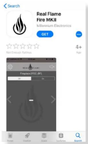
Download the Real Flame Fire MKII App from the App store or play store if you're an Android user.
Step 3
Open the App and click on Set up if you are a new user and have not established connection to your fireplace prior to this.

Step 4
When this screen pops up please switch your fireplace off for 10 seconds and switch on again from the isolation switch and click on Minimise App. If it's already off, switch on the fireplace from the isolation switch and then click on Minimise App button.

Step 5
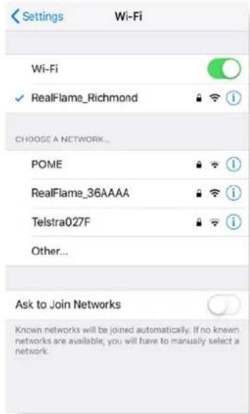
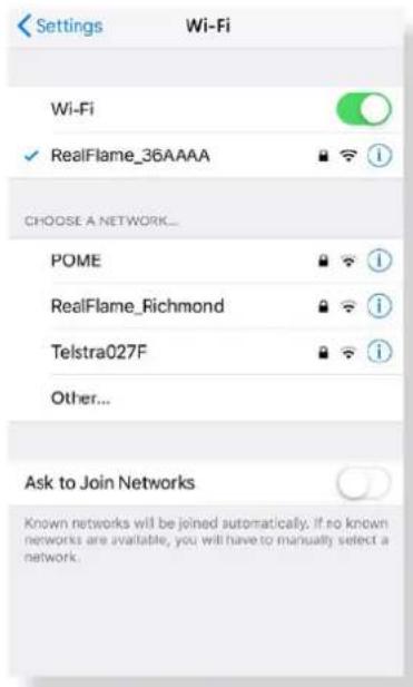
Go to the WiFi setting on your phone and select your fireplace when the device prompts you to choose a network. In this example the RealFlame_36AAAA is the fireplace to select.
Step 6
Once you select the network of your fireplace you will be transported to a screen to input the network password. The password will be "realflame".

Step 7
Once the fireplace is connected click on the information button and select auto join for ease of connection in the future.
Step 8
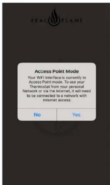
Open the App and click on NO when this pops up. Clicking NO would prompt the device to access the fireplace in the access point mode, which means you have connected to the device using the fireplace WiFi.
*Check Step 11 under "Setting up remote access to the fireplace" to connect to your fireplace from any location.
Step 9
Congrats you have connected to the fireplace. Sit back, relax and increase or decrease the temperature as you please.

Step 10
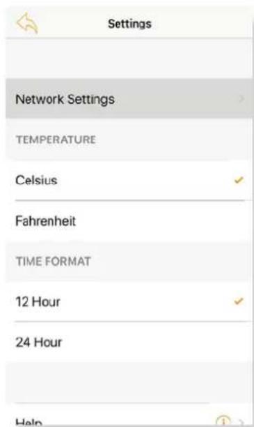
In case you want to change the name of your fireplace connection, click on the settings button on the left corner and it will transport you to the settings tab. Click on Network settings.
Step 11
Click OK when the option to rename appears and input the new name.

Setting up remote access to the fireplace
(eg: Using the phone or tablet remotely to activate the fire when not at residence) – Note gas fireplace requires connection to home WiFi network.
Step 12
To access your fireplace from remote locations click on the Yes button when this tab opens.

Step 13
Select your home WiFi network and input the password. This process links the fire to your WiFi. Make sure your phone is connected to the same network the fire is.

Step 14
Subject to operating system the following should occur - Once the connection is established, the system will transport you to the screen below. Click Yes.
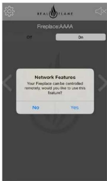
If the above does not occur - close app.
Open WiFi settings and connect phone to home WiFi network. Leave WiFi connection to home WiFi network on.
Open Realflame fire app.
Click YES
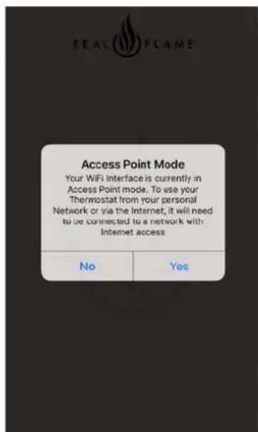
Step 15
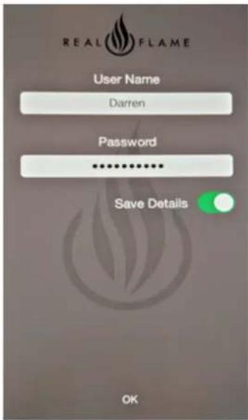
Clicking Yes will open the registration section which once completed will allow you to access your fireplace from anywhere. Put in the details of your preferred username and preferred password (eg John Smith p/w delta22), check the save details tab and click ok. Record the username and password for future reference.

Step 16
Device should now be connected. Note - web service appears on screen

Step 17
Using device turn off fireplace.
Turn off WiFi connection to home network and to appliance if connected.
Close app.
Turn on app and select OK
Step 18
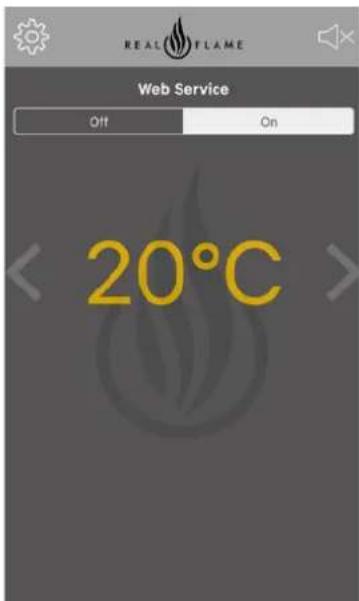
Sit back, relax and enjoy the warmth from your fireplace. (Note - web service appears on screen)
Fireplace may take up to 30 seconds to receive signal from device.
Pushing the Fireplace to a different home or local network after initial setup
Pushing the Fireplace to a different home or local network after it has previously been set up, is done at Fireplace power on, when the fireplace is powered off at the Main switch, upon being powered on, the Fireplace will show its Access point (Realflame_XXXXXX) for 30 seconds. If you join the access point with your mobile device, you will be able to change the network the Fireplace is currently connected with via the mobile App. If you do not join the Access point the Fireplace will join the network that is has settings saved for or if there are no settings, it will stay in Access Point mode.
Note: If you join the access point by accident on power on, you can simply power off the Fireplace and power on again, after the 30 seconds the Fireplace will join the network with its saved settings
Note: If not connected to WiFi you can still control the fire via 4G or 5G network.
ANDROID DEVICE INSTRUCTIONS
Step 1
Open Google play store on your device and search for the 'Real Flame Fire MKII' App.

Step 2
Download the App on your mobile device and close play store.

Step 3
Before you open the Fireplace app, open your WiFi setting and select the fireplace to connect to it as shown below.
The password to connect is "realflame".

Step 4
Now open the app and select yes when the screen prompts you to connect the fireplace to your personal network as per below.

Step 5
Once you click yes, this screen will appear. You have to now connect the fireplace to your WiFi network. Select your network and enter the password. Click 'OK' once you have entered your details.

Step 7
Once the fireplace is connected to your personal WiFi network, close the app and open your WiFi settings. Connect to your personal WiFi network and re open the app once again.

Step 8
Congratulations your fire place is now connected!
Once you open the app once again, you'll get a prompt to control your fireplace remotely. Click yes and proceed.

Step 9
Enter the user name and password of your choice. Please remember this log in detail as it will help you to access the fireplace remotely.

Step 10
Congratulations! You can now access your fireplace remotely without the need to connect to your personal WiFi network.

Step 11
Now you can regulate the temperature of the fireplace as per your liking.

Step 12
To rename the fireplace and personalise it, go to settings and rename as per your liking.

TROUBLESHOOTING FOR YOUR FIREPLACE
| Problem Possible | Cause Suggested Solution | |
| When the remote is activated nothing happens | Gas supply is turned off or low pressure switch not activated.Powerflue fan loom is not connected Flues not connected or incorrectly installed; refer red/black labels on flues. | Reprogram the remote to the receiver(Refer to the Remote section in the manual) |
| The remote batteries are flat Replace the Battery | ||
| The remote operates but appliance does not operate or spark | Gas supply is turned off or low pressure | Check if the gas supply is turned on and the pressure is optimum |
| Powerflue fan loom is not connected | Connect Powerflue fan loom | |
| Flues not connected or incorrectly installed; refer red/black labels | Check Installation and connect flues | |
| The fire cuts off and won't relight The | over temp snap disc has been activated. | Allow the fire to cool down and then try to relight the fire. If the fire fails to relight, contact the manufacturer. |
| The fan will not come on | Possible caused by overheat or electrical fault. | Contact the manufacturer. |
| Flame appears to be low | Pressure not set | All pressures are set in the factory at the time of manufacture, however the installing plumber mus make sure the pressures are correct. |
Techrite Flash code sequence-normal operation
Off Red 1 Long
Prepurge Red 1 Long 5 Short
Sparking Red 1 Long 1 Short
Normal running operation Red 1 Long
Normal postpurge (300 seconds) Red 1 Long 5 Short
Off Red 1 Long
Other Code
Fault Lockout Red 2 Long 1 Short
*If your fireplace still does not operate correctly consult your dealer. All service and repairs should be performed by an authorised agency. All spare parts and optional trim finishes are available from Glen Dimplex Pty Ltd.
INSTALLATION INSTRUCTIONS
natural_image
Modern living room interior with beige sofa, fire extinguisher, and large stone wall (no visible text or symbols)UNIT DIMENSIONS


| UNIT A | B C D E F | G H I J K L M | N | |||||||||||
| E1200 | 752 | 601 | 131 | 452 | 74.5 | 74.5 | 1291 | 1186 | 364 | 1400 | 46 | 657 | 170 | 645 |
| E1800 | 1052 | 901 | 131 | 452 | 74.5 | 74.5 | 1891 | 1786 | 364 | 2000 | 46 | 657 | 170 | 645 |
| UNIT | O | P | QRS | ||
| E1200 | 468 | 143 | 56 | 45 | 52 |
| E1800 | 468 | 143 | 56 | 45 | 52 |
MINIMUM FRAMEOUT DIMENSIONS
50MM TRIM

| UNIT A | B C D | |||
| E1200 | 660 | 1420 | 460 | 143 |
| E1800 | 660 | 2020 | 460 | 143 |
NOTE :
The appliance is to be installed prior to wall cladding and finishes. Standard plaster board in 10mm or 13mm thickness is a suitable cladding to use on frame work and beyond trim.
18MM TRIM
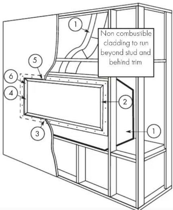
- Install Element MK2 onto base and connect flue, gas and power.
- Fit 18mm trim assembly.
- Attach 4 sided flange kit to frame.
- Remove 18mm assembly.
- Clad wall to flange kit and finish.
- Refit 18mm trim assembly.
NOTE:
If the wall is being plastered we recommend fixing stopping bead up to the flange to give a clean shadow line. The depth of the flange profile is 22mm to allow for tiling or rendering. If plaster is used we recommend packing out to 22mm.
1200 TRIM DIMENSIONS
50MM TRIM

18MM TRIM FLANGE KIT

18MM LOW PROFILE TRIM
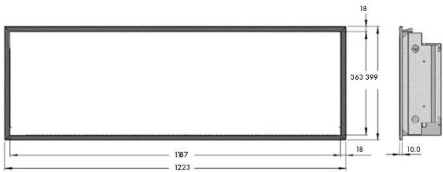
1800 TRIM DIMENSIONS
50MM TRIM

18MM TRIM FLANGE KIT

18MM LOW PROFILE TRIM

INSTALLING ELECTRONIC EQUIPMENT ABOVE YOUR FIREPLACE

Fig. Side View of the Wall and Fireplace
* A common installation configuration includes the mounting of a TV, soundbar, speakers, or other electrical/electronic equipment above a gas fireplace. If installing any equipment above a Real Flame gas fireplace, a minimum clearance of 300mm from the top edge of the fascia is recommended. Installation of a mantel shelf or an equipment recess is not generally required, but may be added to further protect equipment from the heat which will naturally rise from any gas heating appliance. Due to the wide variety of commercially available equipment which may be installed above a gas fireplace, Glen Dimplex recommends that end users contact their equipment manufacturer to determine suitability in advance of installation. Glen Dimplex offers no guarantees around, nor assumes any responsibility for the suitability of electrical equipment installed in this configuration.
Select a location where the fire can be supervised during operation. An electrical isolation switch must be fitted at the appliance or on an adjacent wall to allow for emergency shutdown and maintenance. Installation must meet Australian gas codes AS5601.1-2013
INSTALLATION CLEARANCES
Clearances from combustible materials
| Floor | 0mm | |
| Sides | 25mm | |
| Top | 25mm | |
| Flue outer | 25mm | |
| Front | 25mm | |
| Back | 25mm |
Note: Once installed no combustible items should be placed within 600mm of the fire viewing window.

GAS CONNECTION 15mm (1/2") Compression union ELECTRICAL CONNECTION 3 Pin 10 Amp GPO plug POWER RATING OF APPLIANCE 230V 50Hz 0.55 Amp
INSTALLATION CODES
Note appliance gas type – Natural gas/LPG/ULPG. Should the appliance be the incorrect gas type, please contact the supplier for conversion details.
Installers – Please ensure the installation and instruction manuals supplied with this appliance are supplied to the customer and the customer is trained on how to operate the appliance correctly.
Do not exceed maximum rated pressures.
Appliance must be installed with gas installation code (AS/NZS5601.1-2013) and applicable electrical installation code (AS3000).
Test for gas leaks prior to operating appliance.
Check gas pressures and adjust if incorrect.
FLUE CONFIGURATIONS
0-5m- Aluminum flexi flue as per 0-5m IOM.
5-10m- Aluminum flexi flue insulated. Refer to 5-10m insulated flue run IOM.
10-13.5m- Poly flue system. Refer to 10-13.5m flue configuration.
FLUE SPECIFICATIONS
75mm internal diameter twin walled aluminum flexible flue, supplied in 5m lengths. Flue external diameter approx. 83mm.
Note- U style flue runs must not be installed:

natural_image
Pure electrical circuit lines without any symbolsRecommended Silicon – Non-acetic, neutral cure 150^ C or higher temperature rated.
Bostik RTV 926 or similar.
Flue runs 0m to 5m length (excluding 0-5m rooftop termination)
External wall mount outlet with integrated flue fan (0-5m Flue run model)
External wall mount terminal (Flue fan installed above appliance internally) (0-5m Flue run model)

Flue runs 0m to 5m length rooftop termination only
Vertical roof termination (S/Steel rooftop termination)

FLUE TERMINATION LOCATIONS
This section is used to determine where your Balanced Flue termination will be located. Flue terminations shall not be recessed in walls or sidings.
EXTREMELY IMPORTANT
- In heavy snow areas take extra care to prevent blocking flue termination with snow removal equipment.
- Flue gases exiting flue terminals are very hot and must not be restricted to assure fireplace combustion is not
affected.
- Do not place, build any obstruction, plant any bushes or for any reason attempt to conceal the flue termination. To do so will affect the operation of the fireplace and may be hazardous.
• This unit must always vent directly to outdoors.
Flue runs 0m to 5m length rooftop termination with external motor
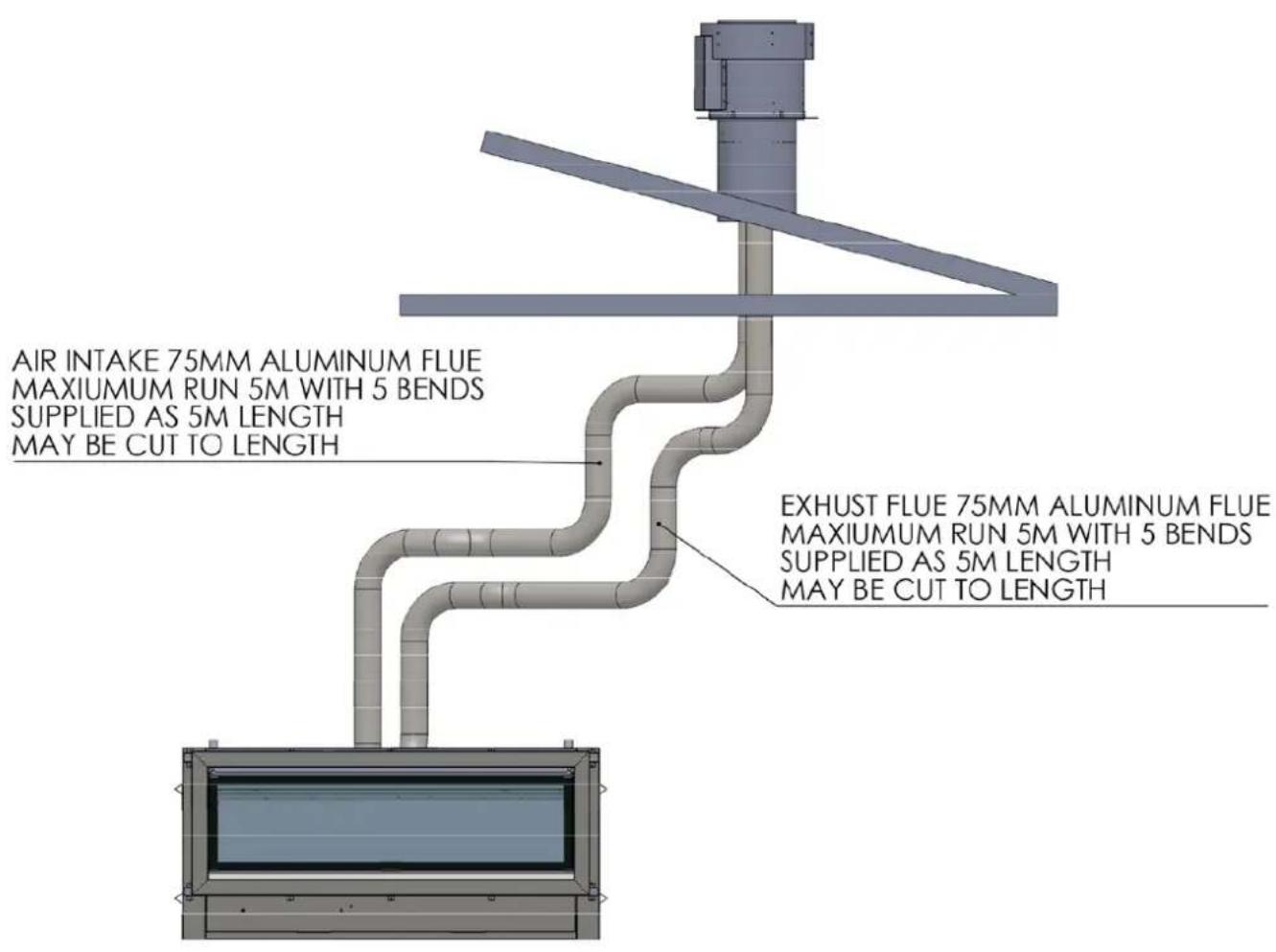
EXTERNAL WALL MOUNTED FAN MODULE INSTALLATION
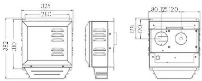
- Wall mounted fan module – terminal must be installed with clearances as specified by AS5601.1 Clause 6.9.3.
- Run exhaust flue and air intake flue as required Maximum run 5m. Flues can be run next to each other. Maintain clearances to combustibles.
- Connection to appliance

natural_image
Close-up of a hand holding a transparent cylindrical metal pipe with concentric grooves (no text or symbols visible)Cut tube to length where required.
Ensure ends are burr free and round, test fit flue will slide over connection.
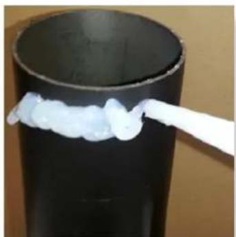
natural_image
Close-up of a black cylindrical object with a white adhesive tape applied, no visible text or symbolsRecommended Silicon - Non-acetic, neutral cure 150°C or higher temperature rated.
Bostik RTV 926 or similar.
Apply an 8mm thick silicon bead fully around heater connection approx. 10mm from the top.
natural_image
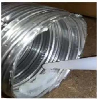
Close-up of a transparent cylindrical pipe with a white plastic liner, showing internal structure and texture (no text or symbols visible)Apply an 8mm silicon bead fully around the inside of the flue end (heater connection end)
Fit flue clamp over flue (loosely).
natural_image
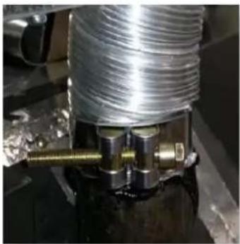
Close-up of a metallic mechanical component with threaded spring and flange (no visible text or symbols)Slide flue onto connection spigot fully.
Tighten clamp fully.
Wipe excess silicon, visually check connection to ensure connection is fully sealed
- Repeat above with air intake flue pipe to heater connection.
- Clip flues as required to provide adequate support.
- Connection to wall mounted fan terminal.

natural_image
Metallic stainless steel appliance with ventilation slots and a side panel (no visible text or symbols)Remove cover from fan terminal
Remove main assembly from the rear wall mounting plate assembly.

natural_image
Interior view of an open metallic industrial box with visible internal components and wiring (no text or symbols)Remove the 5 screws as shown. (Do not remove fan plate screws)
lift off main fan terminal assembly.

natural_image
Metallic mechanical housing with two circular cutouts and bolt holes (no text or symbols visible)Remove wall mount plate from flue connection plate.
natural_image
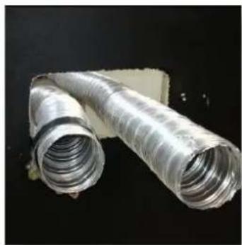
Two coiled metallic pipes with ribbed end caps, displayed against a dark background (no text or symbols visible)Cut flue exhaust tube (hot tube) to length (Approximately flush with wall exit). Connection plate will sit against wall.
Cut Air intake flue.
Ensure ends are burr free and round, test fit flue will slide over connection.
Pull flue through approx. 100mm (will be pushed back once terminal is fitted).
natural_image
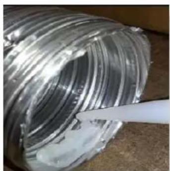
Close-up of a transparent cylindrical pipe with white insulation being smoothed by a white tool (no text or symbols visible)Apply an 8mm silicon bead fully around the inside of the flue end (heater connection end)
Fit flue clamp over flue (loosely).

natural_image
Close-up of hands installing or adjusting a metallic cylindrical component with coiled tubing (no visible text or symbols)Slide flue onto connection spigot fully. Tighten clamp fully.
Wipe excess silicon, visually check connection to ensure connection is fully sealed.

natural_image
Close-up of a hand holding a metallic mechanical component with a transparent cylindrical part, no visible text or symbols.Feed air intake flue pipe through location spigot and fit retaining screw.
Push connection plate into approximate position.
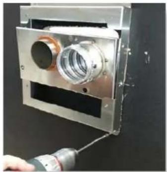
natural_image
Close-up of a metallic mechanical device with a coiled cable, showing internal components and mounting holes (no text or symbols visible)Locate wall mounting bracket into position and affix to wall.

natural_image
Close-up of a metallic mechanical device with a circular aperture and internal tubing (no visible text or symbols)Assemble spigot connection plate assembly to wall mounting bracket. (4 screws)

natural_image
Metallic housing with two circular openings and a coiled cable, no visible text or symbolsFeed power cable through bottom area of bracket.

natural_image
Interior view of an industrial control box with visible wiring, tubing, and components (no text or symbols)Assemble main body assembly onto wall mounting bracket, feed power cable through grommet hole prior to fitting. (refit 5 screws as shown and tighten) Main body assembly must sit flush up against the mounting bracket and seal.

natural_image
Close-up of a hand using a tool to adjust or install a flexible electrical component, no visible text or symbols.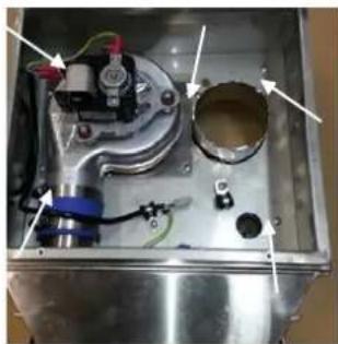
natural_image
Interior view of a metallic industrial or laboratory equipment housing with visible components and wiring (no text or symbols)
natural_image
Close-up of a hand holding a tool interacting with a mechanical device (no visible text or symbols)Connect power cable connector.
Fit cable clamp to cable.
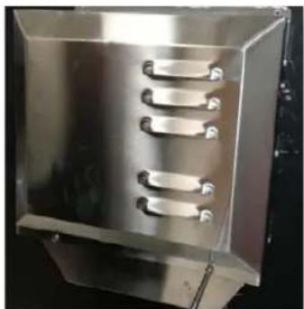
natural_image
Metallic stainless steel industrial machine with three side slots (no visible text or symbols)Fit front cover.
0M-5M FLUE
INTERNAL FAN AND WALL TERMINATION INSTALLATION
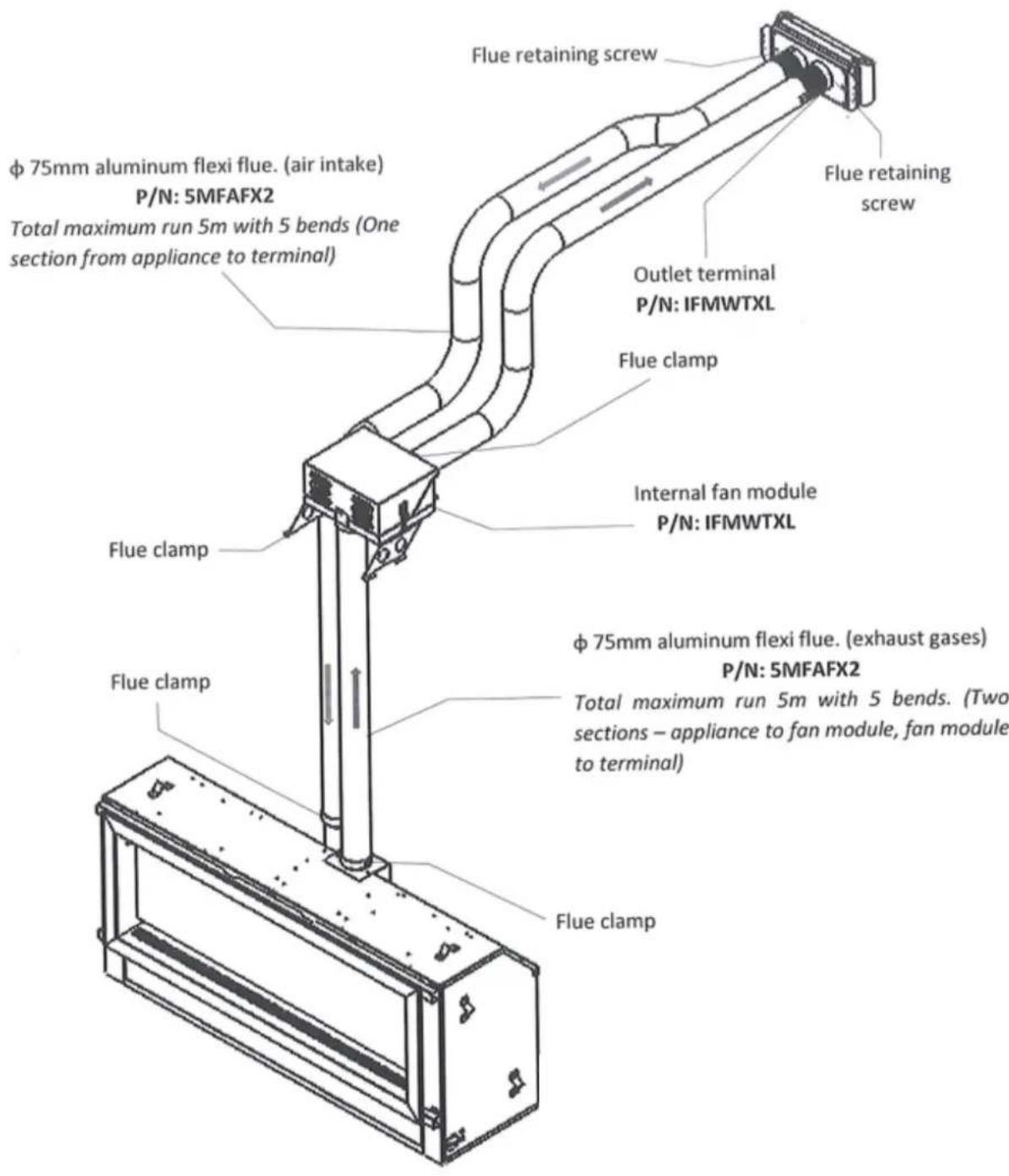
Setup with internal fan module with wall termination - appliance mounted
Maximum 5m flue length
Wall termination
- Wall terminal must be installed with clearances as specified by AS5601.1-2013 Clause 6.9.3
- Run exhaust flue and air intake flue as required - Maximum run 3m per flue. Flues can be run next to each other. Maintain clearances to combustibles.
- Connection to appliance


natural_image
Close-up of a hand holding a transparent cylindrical metal wire, showing concentric grooves (no text or symbols visible)Check 75mm flue piece for correct shape and fitment onto appliance spigot.
Ensure ends are burr free and round, test fit flue will slide over the connection.

natural_image
Close-up of a black cylindrical object with a white adhesive tape attached, showing a glossy texture (no text or symbols visible)Recommended Silicon - Non-acetic, neutral cure 150°C or higher temperature rated. Bostik RTV 926 or similar.
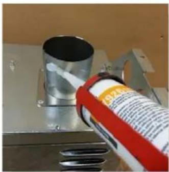
Apply an 8mm thick silicon bead fully around heater connection approx. 10mm from the top.
natural_image
Close-up of a spray bottle dispensing liquid onto a metal surface, with no visible text or symbols.Apply an 8mm thick silicon bead fully around the lower fan connection spigot approx. 10mm from the end.

natural_image
Close-up of a transparent cylindrical pipe with white foam and a white tool inserted, no visible text or symbolsApply an 8mm silicon bead fully around the inside of the flue end, both ends.

natural_image
Close-up of a metal component being processed with a wrench, no visible text or symbolsTurn fan assembly upside down and slide 65mm flue section fully onto spigot.
Fit flue clamp and tighten clamp fully.
Wipe excess silicon, visually check connection to ensure connection is fully sealed.

natural_image
Close-up of a metallic mechanical component with a pipe inserted, no visible text or symbolsFit 2nd flue clamp loosely onto the 65mm section of flue.
(Note 90° left connection is not available and must be done using the 90° right connection fan location and placing a bend in the flue to head in the LH direction.
Lift fan assembly into appliance and locate onto flue connection. Insert fully. Locate fan in the required direction. Screw fan assembly down onto the appliance. (Screws prefitted into holes are located on the appliance for direct out back connection and 90° to right connection.)
Locate 2nd clamp onto lower connection and tighten clamp fully.
Wipe excess silicon, visually check connection to ensure connection is fully sealed.

natural_image
Close-up of a mechanical assembly with metallic components and mounting base (no visible text or symbols)
natural_image
Close-up of a metallic mechanical component mounted on a black base, no visible text or symbols
natural_image
Close-up of a hand holding a transparent plastic cylindrical container with concentric rings (no text or symbols visible)Fit hot exhaust flue pipe from outlet termination to fan outlet connection.
Cut tube to length where required.
Ensure ends are burr free and round, test fit flue will slide over connection.

natural_image
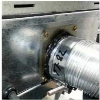
Close-up of a coiled plastic pipe with a white tool inserted, no visible text or symbolsApply an 8mm thick silicon bead fully around heater connection approx. 10mm from the top.
Apply an 8mm silicon bead fully around the inside of the flue end (heater connection end)
Fit flue clamp over flue (loosely).
natural_image
Close-up of a metallic mechanical component with threaded shaft and mounting holes (no visible text or symbols)Slide flue onto connection spigot fully.
Tighten clamp fully.
Wipe excess silicon, visually check connection to ensure connection is fully sealed.

natural_image
Close-up of a mechanical component with a black cylindrical part and white striped band, mounted on a metallic frame (no visible text or symbols)Connect power lead to fan module. Ensure lead is clipped to support where required.
Do not use connection to support lead.

natural_image
Close-up of a hand holding a transparent plastic cylindrical object with concentric grooves (no text or symbols visible)Fit air intake flue pipe to heater connection.
Cut tube to length where required.
Ensure ends are burr free and round, test fit flue will slide over connection.

natural_image
Close-up of a black cylindrical object with a white adhesive tape applied, no visible text or symbolsApply an 8mm thick silicon bead fully around heater connection approx. 10mm from the top.

natural_image
Close-up of a transparent cylindrical pipe with white insulation, being cut with a white plastic clip (no text or symbols visible)Apply an 8mm silicon bead fully around the inside of the flue end (heater connection end)
Fit flue clamp over flue (loosely).

natural_image
Close-up of a metallic mechanical component with coiled spring and threaded fittings (no visible text or symbols)Slide flue onto connection spigot fully.
Tighten clamp fully.
Wipe excess silicon, visually check connection to ensure connection is fully sealed

natural_image
Close-up of a metallic coiled hose assembly with metal components and a bolted joint (no visible text or symbols)Clip flues as required to provide adequate support.
7. Connection to wall terminal
Loose fit connections (wall termination connections)


natural_image
Metallic rectangular metal bracket with rounded corners and a flat top (no text or symbols visible)
natural_image
Two coiled metallic pipes with coiled black bands, displayed against a dark background (no text or symbols visible)Locate terminal on wall and predrill mounting holes where required.
Cut flue exhaust tube (hot tube) to length (Flue must extend a minimum of 50mm past the exit face of wall.) It is recommended that the tubes are cut slightly longer and pushed back into wall upon fixing of wall terminal. Allow flue movement between terminal and last flue hanging clip.
Cut Air intake as per flue exhaust.
Ensure ends are burr free and round, test fit flue will slide inside both the hot exhaust connection and air intake connection.
natural_image
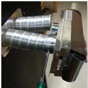
Close-up of a mechanical device with coiled metallic components and a black handle (no visible text or symbols)Feed hot exhaust flue into connection, ensure inserted 50mm. Fit retaining screw from below.

natural_image
Close-up of a mechanical assembly with coiled metal components and a green control panel (no visible text or symbols)Feed air intake flue into connection, ensure inserted 50mm. Fit retaining screw from below.

natural_image
Metallic cylindrical mechanical component with a label, no visible text or symbols on the main body.Push terminal into approximate position and affix onto wall.

natural_image
Close-up of a hand using a drill bit to lift a metallic rectangular component (no visible text or symbols)Setup with internal fan module with wall termination - mid flue mounted
Maximum 5m flue length

natural_image
Technical line drawing of a ductwork or piping system mounted on a rectangular base (no text or symbols)Wall termination
- Wall terminal must be installed with clearances as specified by AS5601.1-2013 Clause 6.9.3
- Run exhaust flue and air intake flue as required - Maximum total run 5m per flue. Flues can be run next to each other. Maintain clearances to combustibles.
- Mount fan controller in the required location. (Access to the fan module is required for servicing, if the fan module is located inside a boxed frame, allow a 450 x 450 access panel).
- Connection to fan module to appliance run flue from appliance to bottom entry on fan module. Support flue with brackets as required.

natural_image
3D rendering of a mechanical camera mounted on a rail track (no text or symbols visible)
natural_image
Close-up of a hand holding a transparent cylindrical object with concentric grooves (no text or symbols visible)Cut tube to length where required.
Ensure ends are burr free and round, test fit flue will slide over connection.

natural_image
Close-up of a black cylindrical object with a white adhesive tape applying white foam (no text or symbols visible)Apply an 8mm thick silicon bead fully around heater connection approx. 10mm from the top.

natural_image
Close-up of a transparent cylindrical pipe with white insulation, being smoothed by a white tool (no text or symbols visible)Apply an 8mm silicon bead fully around the inside of the flue end (heater connection end)
Fit flue clamp over flue (loosely).

natural_image
Close-up of a mechanical assembly with coiled metallic tubing and a brass fitting (no visible text or symbols)Slide flue onto connection spigot fully.
Tighten clamp fully.
Wipe excess silicon, visually check connection to ensure connection is fully sealed
natural_image
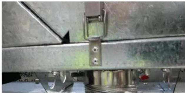
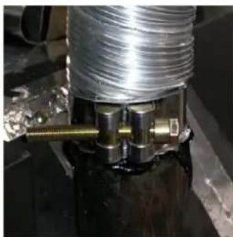
Close-up of a metallic mechanical assembly with bolts and a central bracket (no visible text or symbols)Repeat for connection to underside of fan module.
natural_image
Close-up of a mechanical assembly with coiled metallic tubing and a brass fitting (no visible text or symbols)Repeat for air intake flue connection.
natural_image
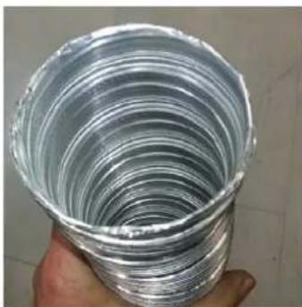
Hand holding a transparent cylindrical object with concentric rings (no text or symbols visible)Fan module outlet connection
Cut tube to length where required. Ensure ends are burr free and round, test fit flue will slide over connection.

natural_image
Close-up of a coiled plastic pipe with a white tool inserted, no visible text or symbolsApply an 8mm thick silicon bead fully around heater connection approx. 10mm from the top.
Apply an 8mm silicon bead fully around the inside of the flue end (heater connection end)
Fit flue clamp over flue (loosely).

natural_image
Close-up of a metallic mechanical component with threaded end and bolted base (no visible text or symbols)Slide flue onto connection spigot fully.
Tighten clamp fully.
Wipe excess silicon, visually check connection to ensure connection is fully sealed.

natural_image
Close-up of a mechanical component with a black cylindrical body and white adhesive tape, mounted on a metallic frame (no visible text or symbols)- Connect power lead to fan module. Ensure lead is clipped to support where required.
Do not use connection to support lead.
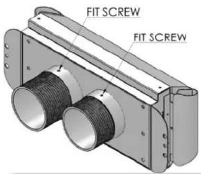
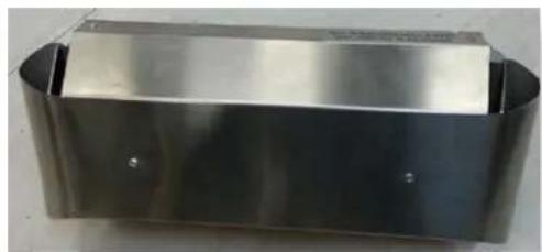
Connection to wall terminal
Loose fit connections (wall termination connections)
natural_image
Metallic rectangular metal bracket with rounded corners and a flat top (no text or symbols visible)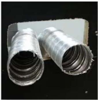
natural_image
Two coiled metallic pipes with visible insulation, placed on a white rectangular base (no text or symbols)Locate terminal on wall and predrill mounting holes where required.
Cut flue exhaust tube (hot tube) to length (Flue must extend a minimum of 50mm past the exit face of wall.) It is recommended that the tubes are cut slightly longer and pushed back into wall upon fixing of wall terminal. Allow flue movement between terminal and last flue hanging clip.
Cut Air intake as per flue exhaust.
Ensure ends are burr free and round, test fit flue will slide inside both the hot exhaust connection and air intake connection.

natural_image
Close-up of a mechanical device with coiled metallic components and a tool, no visible text or symbolsFeed hot exhaust flue into connection, ensure inserted 50mm. Fit retaining screw from below.

natural_image
Industrial machine with coiled metal coils and green frame (no visible text or symbols)Feed air intake flue into connection, ensure inserted 50mm. Fit retaining screw from below.
INTERNAL FAN & ROOF TERMINATION

Setup with internal fan module with rooftop termination - mid flue mounted
Maximum 5m flue length
Note- fan module can be appliance mounted or mid mounted when finishing with the rooftop termination.
Rooftop termination
- Rooftop termination must be installed with clearances as specified by AS5601.1-2013.
- Run exhaust flue and air intake flue as required - Maximum total run 5m per flue. Flues can be run next to each other. Maintain clearances to combustibles.
- Mount fan controller in the required location. (Access to the fan module is required for servicing, if the fan module is located inside a boxed frame, allow a 450 x 450 access panel).

natural_image
3D rendering of a mechanical sensor or camera mounted on a structural frame (no text or symbols visible)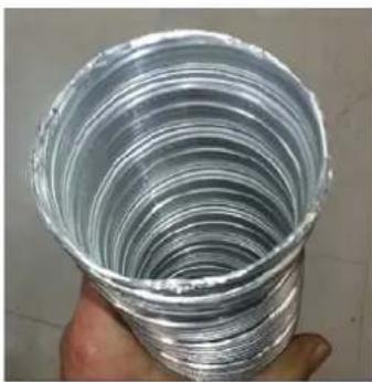
natural_image
Hand holding a transparent cylindrical object with concentric grooves (no text or symbols visible)Run flue from appliance to bottom entry on fan module.
Support flue with brackets as required
Cut flue to length to suit connection.
Ensure ends are burr free and round, test fit flue will fit over connection.

natural_image
Close-up of a black cylindrical container with a white adhesive tape applied to its side (no text or symbols visible)Apply an 8mm thick silicon bead fully around heater connection approx. 10mm from the top.

natural_image
Close-up of a transparent cylindrical pipe with a white plastic tip inserted, showing internal structure (no text or symbols visible)Apply an 8mm silicon bead fully around the inside of the flue end (heater connection end)
Fit flue clamp over flue (loosely).

natural_image
Close-up of a mechanical assembly with coiled spring and brass fittings (no visible text or symbols)Slide flue onto connection spigot fully.
Tighten clamp fully.
Wipe excess silicon, visually check connection to ensure connection is fully sealed
natural_image
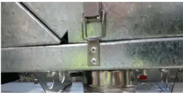
Close-up of a metallic mechanical assembly with bolts and a red seal (no visible text or symbols)Repeat for connection to underside of fan module.
natural_image
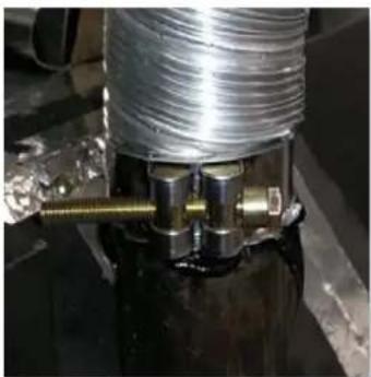
Close-up of a mechanical assembly with coiled metallic components and a brass fitting (no visible text or symbols)Repeat for air intake flue connection.

natural_image
Close-up of a hand holding a transparent cylindrical object with concentric rings (no text or symbols visible)- Fan module outlet connection
Cut tube to length where required.
Ensure ends are burr free and round, test fit flue will slide over connection.

natural_image
Close-up of a transparent cylindrical pipe with a white plastic tip inserted, showing internal structure (no text or symbols visible)Apply an 8mm thick silicon bead fully around heater connection approx. 10mm from the top.
Apply an 8mm silicon bead fully around the inside of the flue end (heater connection end)
Fit flue clamp over flue (loosely).
natural_image
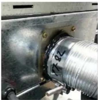
Close-up of a metallic mechanical component with threaded shaft and flange (no visible text or symbols)Slide flue onto connection spigot fully.
Tighten clamp fully.
Wipe excess silicon, visually check connection to ensure connection is fully sealed.
natural_image
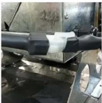
Close-up of a mechanical component with a metallic shaft and circular opening, no visible text or symbols- Connect power lead to fan module. Ensure lead is clipped to support where required.
Do not use connection to support lead.
6. Connection to rooftop terminal
Prepare roof penetration. Remove cowl from termination if fitted.

natural_image
3D technical illustration of a mechanical component with concentric cylindrical sections and mounting holes (no text or symbols)
natural_image
3D rendering of a mechanical component with layered structure (no text or symbols)Cut rooftop penetration to length if required.
Install in to roof penetration.
Install supports for base of penetration kit.
natural_image
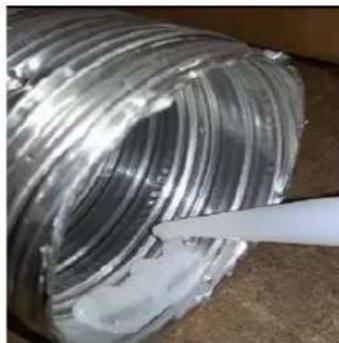
Close-up of a coiled metal pipe with white insulation, being pointed at by a white tool (no text or symbols visible)Connect hot exhaust flue and air intake flue as per below.
Apply an 8mm silicon bead fully around the inside of the flue end
Fit flue clamp over flue (loosely).

Slide flue onto connection spigot fully.
Tighten clamp fully.
Wipe excess silicon, visually check connection to ensure connection is fully sealed.
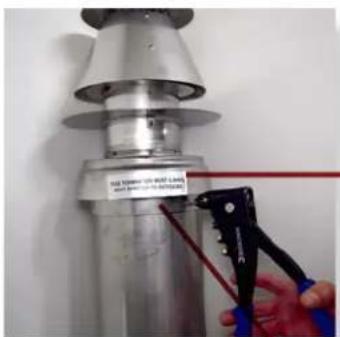
IMPORTANT- Apply silicon bead between inner connection of cowl and flue pipe to seal inner flue to cowl. Outer does not require sealing.
Fit roof sealing method (Decktite or similar).
Ensure flue is supported and clipped where required.
Screw or rivet in 3 places to hold in place.
ROOFTOP TERMINATION WITH EXTERNAL MOTOR

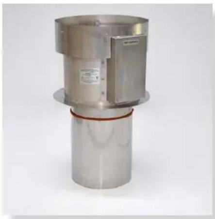
Setup with external rooftop termination
Maximum 5m flue length
Rooftop termination
-
Rooftop fan module – Terminal must be installed with clearances as specified by AS/NZS 5601.1 Clause 6.9.3
-
Run exhaust flue and air intake flue as required
-
Maximum run 5mts. Flues can be run next to each other. Maintain the required clearances to combustibles.
natural_image
Metallic cylindrical device with attached housing and red ring (no visible text or symbols)
natural_image
Close-up of a hand holding a metallic mechanical component being injected with a digital probe (no visible text or symbols)On the heater connection end - Fit clamp loosely & apply silicon inside the pipes. Apply an 8mm silicon bead fully around the inside of the flue and on the heater spigot. Smear the silicon around the spigot and pipe.

natural_image
Close-up of industrial pipe fittings and a yellow clamp securing a black cylindrical component (no visible text or symbols)Recommended Silicon - Non-acetic, neutral cure 150°C or higher temperature rated. Bostik RTV 926 or similar.

natural_image
Close-up of a mechanical assembly with coiled metal tubing and a cylindrical component (no visible text or symbols)Slide flue onto connection spigot fully. Tighten clamp fully. Wipe excess silicon, visually check connection to ensure connection is fully sealed.
Repeat above with air intake flue pipe to heater connection.
Clip flues as required to provide adequate support.

Insert the roof penetration and fix firmly to the roof structure using appropriate supports.
The roof penetration flue is a 250mm rigid flue.
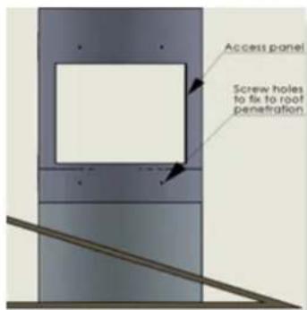
Fit the access panel to the roof penetration.
Use the screw holes fix the access panel to the roof penetration.

natural_image
3D rendering of a mechanical component with cylindrical pipes mounted on a base (no text or symbols visible)Run flue pipes through the access cut outs before fitting the termination on for ease of installation.
(The picture is a reference only. Take care not to flex/bend the pipe too sharply and risk slitting the pipe)

Fit the termination on to the access panel and match the rivet holes to rivet the termination to the access panel.
Use only the rivets provided.

natural_image
Person pouring liquid from a bottle into a metal mixing machine (no visible text or symbols)
natural_image
Close-up of a metallic mechanical component with internal cavities and a red banner (no visible text or symbols)On the termination end - Fit clamp loosely & apply silicon inside the pipes. Apply an 8mm silicon bead fully around the inside of the flue and on the flue spigot. Smear smoothly around the surfaces.
Recommended Silicon – Non-acetic, neutral cure 200°C or higher temperature rated. Bostik RTV 922 or similar.
natural_image
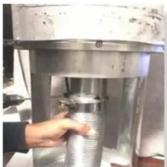
Hand operating a cylindrical mechanical device with metallic components (no visible text or symbols)Slide flue onto connection spigot fully. Tighten clamp fully. Wipe excess silicon, visually check connection to ensure connection is fully sealed.
Ensure that the pipes are connected correctly and are not inverted.
Use the labels to identify exhaust and intake spigots

natural_image
Close-up of a metallic cylindrical device with coiled tubing and a red arrow pointing to a component (no visible text or symbols)Connect the fan power cable from the appliance to the termination.
Ensure the cable is clamped only to the intake pipe to secure the cable from hanging loose & touching the hot flue gases pipe.
Use the clamp provided. The clamp can be opened like a collar and fitted around on the flue.

natural_image
Close-up of hands installing or adjusting a metal cylindrical component (no visible text or symbols)
natural_image
Close-up of a metal pipe being inserted into a cylindrical container, with a green tool partially visible (no text or symbols)Flex collar and fit around the access panel. Socket the collar all the way up close to the air intake slots Ensure there is a rubber seal top and bottom of the collar.
Use only the screws provided to tightly fit the collar to seal the access panel.
5-10M INSULATED FLUE CONFIGURATION
INSTALLATION INSTRUCTIONS
LOCATION
Select a location where the fire can be supervised during operation. An electrical isolation switch must be fitted at the appliance or on an adjacent wall to allow for emergency shutdown and maintenance. Installation must meet Australian gas codes AS5601.1-2013
INSTALLATION CLEARANCES
Clearances from combustible materials
| Floor | 0mm | |
| Sides | 25mm | |
| Top | 25mm | |
| Flue outer | 25mm | |
| Front | 25mm | |
| Back | 25mm |
Note: Once installed no combustible items should be placed within 600mm of the fire viewing window.

GAS CONNECTION 15mm (1/2") Compression union ELECTRICAL CONNECTION 3 Pin 10 Amp GPO plug POWER RATING OF APPLIANCE 230V 50Hz 0.55 Amp
INSTALLATION CODES
Note appliance gas type - Natural gas/LPG/ULPG. Should the appliance be the incorrect gas type, please contact the supplier for conversion details.
Installers – Please ensure the installation and instruction manuals supplied with this appliance are supplied to the customer and the customer is trained on how to operate the appliance correctly.
Do not exceed maximum rated pressures.
Appliance must be installed with gas installation code (AS/NZS5601.1-2013) and applicable electrical installation code (AS3000).
Test for gas leaks prior to operating appliance.
Check gas pressures and adjust if incorrect.
FLUE CONFIGURATIONS
0-5m- Aluminum flexi flue as per 0-5m IOM.
5-10m- Aluminum flexi flue insulated. Refer to 5-10m insulated flue run IOM.
10-13.5m- Poly flue system. Refer to 10-13.5m flue configuration.
FLUE SPECIFICATIONS
75mm internal diameter twin walled aluminum flexible flue, supplied in 10m lengths. Flue external diameter approx. 83mm.
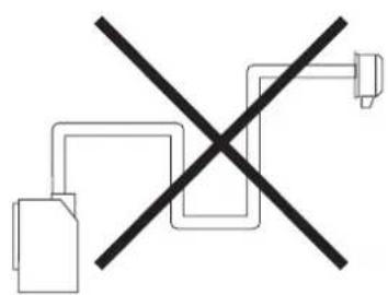
Note- U style flue runs must not be installed:
natural_image
Pure electrical circuit lines without any symbolsRecommended Silicon - Non-acetic, neutral cure 150^ or higher temperature rated.
Bostik RTV 926 or similar.
Flue runs 5m to 10m length (excluding 5-10m rooftop termination)
External wall mount outlet with integrated flue fan (5-10m Flue run model)
External wall mount terminal (Flue fan installed above appliance internally) (5-10m Flue run model)
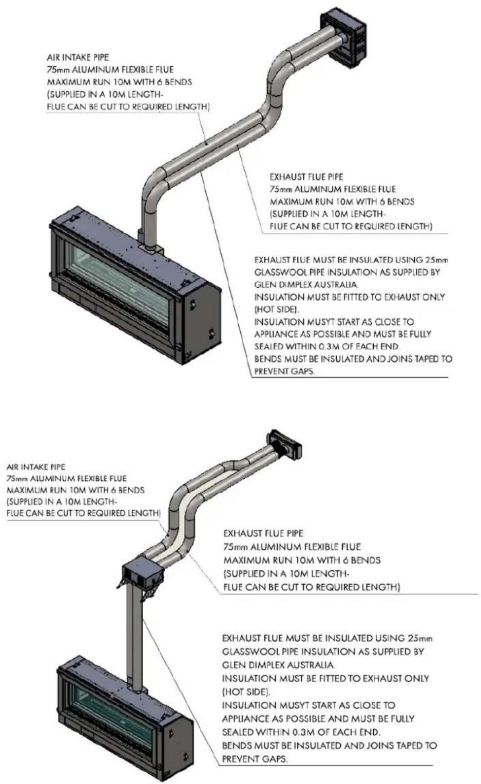
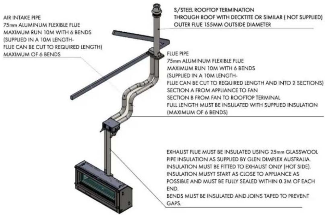
Flue runs 5m to 10m length rooftop termination only
Vertical roof termination (S/Steel rooftop termination)
FLUE TERMINATION LOCATIONS
This section is used to determine where your Balanced Flue termination will be located.
Flue terminations shall not be recessed in walls or sidings.
EXTREMELY IMPORTANT
- In heavy snow areas take extra care to prevent blocking flue termination with snow removal equipment.
- Flue gases exiting flue terminals are very hot and must not be restricted to assure fireplace combustion is not
affected.
- Do not place, build any obstruction, plant any bushes or for any reason attempt to conceal the flue termination. To do so will affect the operation of the fireplace and may be hazardous.
• This unit must always vent directly to outdoors.
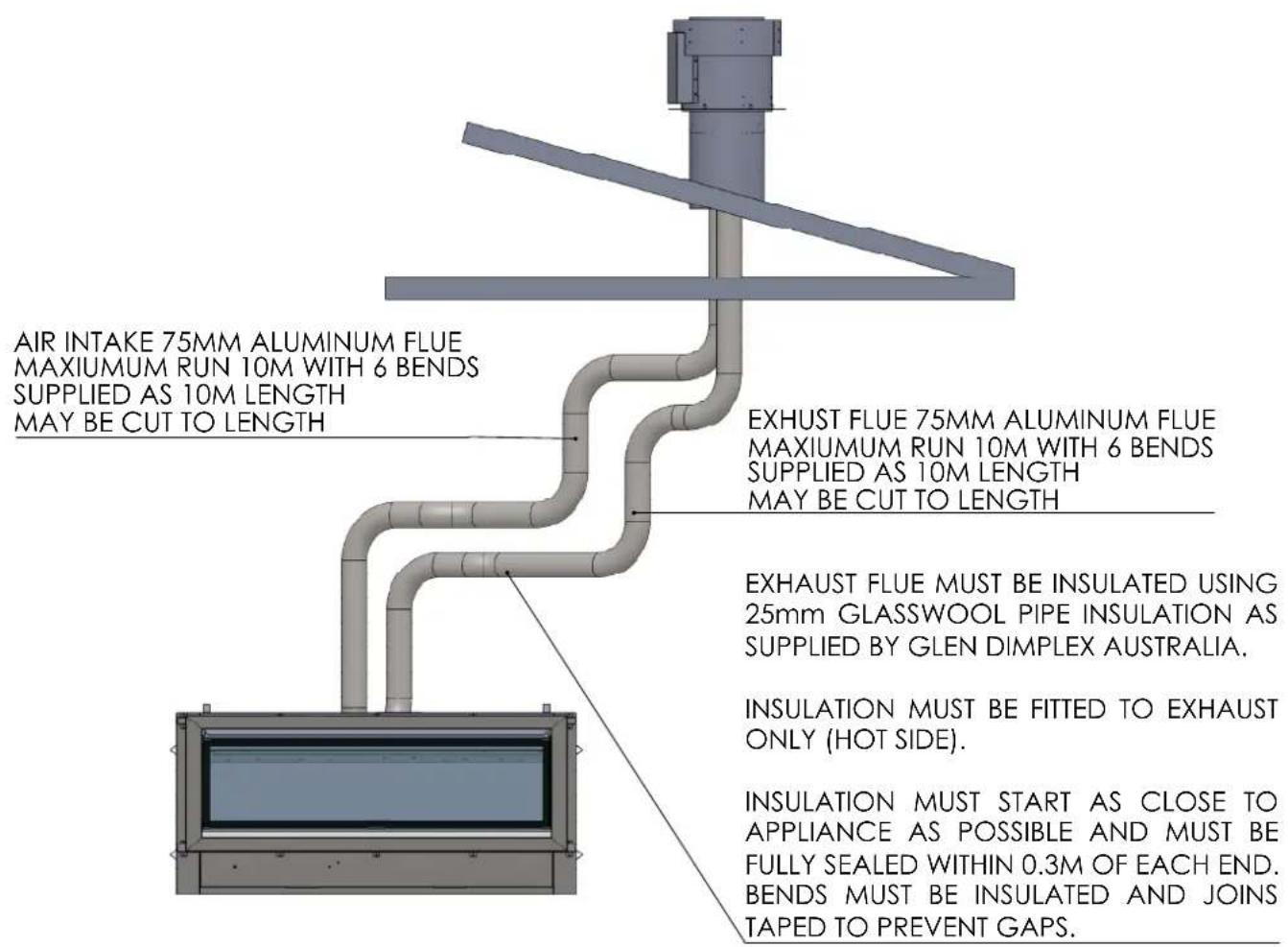
Flue runs 5m to 10m length rooftop termination with external motor
EXTERNAL WALL MOUNTED FAN MODULE INSTALLATION
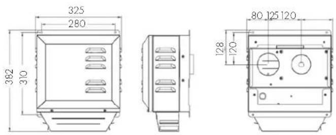
- Wall mounted fan module – terminal must be installed with clearances as specified by AS5601.1 Clause 6.9.3.
- Run exhaust flue and air intake flue as required Maximum run 10m. Flues can be run next to each other. Maintain clearances to combustibles.
- Insulation Instructions-
Exhaust flue must be insulated using 25mm glass wool pipe insulation as supplied by Glen Dimplex Australia. Insulation must be fitted to exhaust (hot side only).
Insulation must start as close to appliance as possible (within 300mm).
Insulation must finish as close to discharge as possible (within 300mm).
Insulation must run around bends.
Insulation to be taped to ensure no gaps.
Insulation may be fitted while running flue or at final stage of installation.
(shown at flue stage in Instructions)
- Connection to appliance

natural_image
Hand holding a transparent plastic cylindrical container filled with coiled metal sheets (no text or symbols visible)Cut tube to length where required.
Ensure ends are burr free and round, test fit flue will slide over connection.

natural_image
Close-up of a black cylindrical container with a white adhesive tape attached, no visible text or symbols.Recommended Silicon - Non-acetic, neutral cure 150°C or higher temperature rated.
Bostik RTV 926 or similar.
Apply an 8mm thick silicon bead fully around heater connection approx. 10mm from the top.
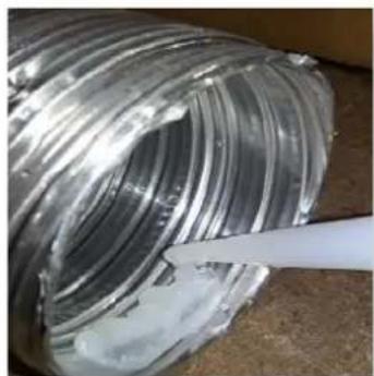
natural_image
Close-up of a transparent cylindrical pipe with white insulation being smoothed by a white tool (no text or symbols visible)Apply an 8mm silicon bead fully around the inside of the flue end (heater connection end)
Fit flue clamp over flue (loosely).

natural_image
Close-up of a metallic coiled spring assembly with brass fittings (no visible text or symbols)Slide flue onto connection spigot fully.
Tighten clamp fully.
Wipe excess silicon, visually check connection to ensure connection is fully sealed
- Repeat above with air intake flue pipe to heater connection.
- Clip flues as required to provide adequate support.
- Connection to wall mounted fan terminal.
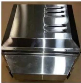
natural_image
Metallic stainless steel appliance with ventilation slots (no visible text or symbols)Remove cover from fan terminal
Remove main assembly from the rear wall mounting plate assembly.

natural_image
Interior view of an open metallic enclosure with internal components and wiring (no visible text or symbols)Remove the 5 screws as shown. (Do not remove fan plate screws)
Lift off main fan terminal assembly.
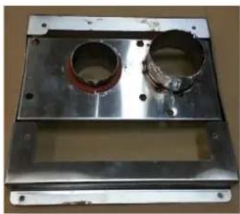
natural_image
Metallic mechanical housing with two circular cavities and bolt holes (no text or symbols visible)Remove wall mount plate from flue connection plate.

natural_image
Two coiled metallic pipes against a dark background (no text or symbols visible)Cut flue exhaust tube (hot tube) to length (Approximately flush with wall exit). Connection plate will sit against wall.
Cut Air intake flue.
Ensure ends are burr free and round, test fit flue will slide over connection.
Pull flue through approx. 100mm (will be pushed back once terminal is fitted).

natural_image
Close-up of a transparent cylindrical pipe with white insulation, being smoothed with a white tool (no text or symbols visible)Apply an 8mm silicon bead fully around the inside of the flue end (heater connection end)
Fit flue clamp over flue (loosely).
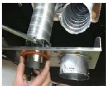
natural_image
Close-up of hands installing or adjusting a metal pipe assembly with coiled ducts (no visible text or symbols)Slide flue onto connection spigot fully. Tighten clamp fully.
Wipe excess silicon, visually check connection to ensure connection is fully sealed.

natural_image
Close-up of a hand holding a metallic mechanical component with a transparent cylindrical housing (no visible text or symbols)Feed air intake flue pipe through location spigot and fit retaining screw.
Push connection plate into approximate position.

natural_image
Metallic cylindrical object with yellow top, isolated on white background (no text or symbols)Fit flue exhaust insulation
Insulated with 25mm foil faces glasswool pipe insulation within 0.3m of each end of flue, as supplied by Glen Dimplex Australia.
Insulation must start as close to the gas space heater as possible
(Only exhaust flue is to be insulated)

natural_image
Close-up of a metallic pipe joint with reflective material, no visible text or symbolsInsulation to be fully closed and sealed along length.

natural_image
Metallic PVC pipe with wrapped insulation, mounted on a stand against a black background (no text or symbols visible)Bends were practical should be insulated, by cutting the insulation into segments and taping together.
natural_image
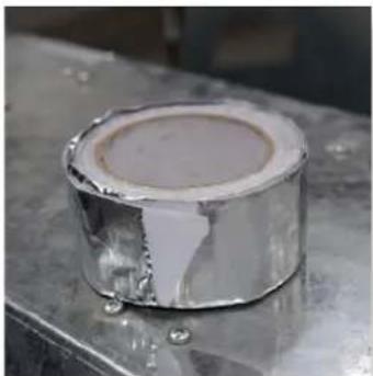
Close-up of a metallic cylindrical object with reflective surface, no visible text or symbolsJoins can be taped together using aluminum foil self adhesive tape.
natural_image
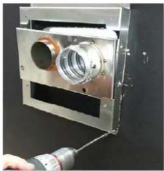
Close-up of a metallic mechanical device with two circular components and a connecting rod (no visible text or symbols)Locate wall mounting bracket into position and affix to wall.

natural_image
Close-up of a metallic mechanical device with a cylindrical component and flanged housing (no visible text or symbols)Assemble spigot connection plate assembly to wall mounting bracket. (4 screws)
natural_image
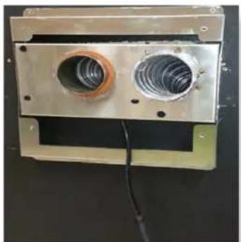
Metallic industrial component with two circular cavities and a black base, no visible text or symbolsFeed power cable through bottom area of bracket.

natural_image
Interior view of an open industrial control box with visible wiring, components, and a central motor (no text or symbols)Assemble main body assembly onto wall mounting bracket, feed power cable through grommet hole prior to fitting. (refit 5 screws as shown and tighten) Main body assembly must sit flush up against the mounting bracket and seal.
natural_image
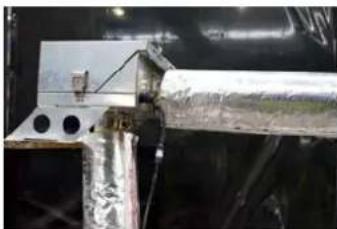
Close-up of a metallic mechanical component with circular holes and a cylindrical shaft (no visible text or symbols)Insulation must be fitted prior and after the inline powerflue fan.
Failure to fit insulation on the exhaust flue may result in condensation failures with the appliance.

natural_image
Close-up of a hand using a screwdriver to adjust internal components of an electronic device (no visible text or symbols)
natural_image
Interior view of an open metallic enclosure with internal components and wiring (no visible text or symbols)
natural_image
Close-up of a hand holding a tool interacting with a mechanical device (no visible text or symbols)Connect power cable connector.
Fit cable clamp to cable.

natural_image
Metallic stainless steel industrial machine with three side slots (no visible text or symbols)Fit front cover.
5M-10M FLUE
INTERNAL FAN AND WALL TERMINATION INSTALLATION

Exhaust flue must be insulated using 25mm glass wool pipe insulation as supplied by Glen Dimplex Australia.
Insulation must be fitted to exhaust (hot side only).
Insulation must start as close to appliance as possible (within 300mm).
Setup with internal fan module with wall termination - appliance mounted
Maximum 10m flue length
Wall termination
- Wall terminal must be installed with clearances as specified by AS5601.1-2013 Clause 6.9.3
- Run exhaust flue and air intake flue as required - Maximum run 10m per flue. Flues can be run next to each other. Maintain clearances to combustibles.
- Insulation Instructions-
Exhaust flue must be insulated using 25mm glass wool pipe insulation as supplied by Glen Dimplex Australia. Insulation must be fitted to exhaust (hot side only).
Insulation must start as close to appliance as possible (within 300mm).
Insulation must finish as close to discharge as possible (within 300mm).
Insulation must run around bends.
Insulation to be taped to ensure no gaps.
Insulation may be fitted while running flue or at final stage of installation.
(shown at flue stage in Instructions)
- Connection to appliance


natural_image
Hand holding a transparent cylindrical object with concentric grooves (no text or symbols visible)Check 75mm flue piece for correct shape and fitment onto appliance spigot.
Ensure ends are burr free and round, test fit flue will slide over the connection.

natural_image
Close-up of a black cylindrical container with a white adhesive tape extending from it, no visible text or symbols.Recommended Silicon - Non-acetic, neutral cure 150deg or higher temperature rated. Bostik RTV 926 or similar.
Apply an 8mm thick silicon bead fully around heater connection approx. 10mm from the top.

natural_image
Close-up of a red spray caner applying white paint to a metallic cylindrical container on a metal workbench (no visible text or symbols)Apply an 8mm thick silicon bead fully around the lower fan connection spigot approx. 10mm from the end.

natural_image
Close-up of a transparent cylindrical pipe with white insulation, being cut with a white tool (no text or symbols visible)Apply an 8mm silicon bead fully around the inside of the flue end, both ends.

natural_image
Close-up of a hand using a tool to adjust a metallic component with threaded end (no visible text or symbols)Turn fan assembly upside down and slide 65mm flue section fully onto spigot.
Fit flue clamp and tighten clamp fully.
Wipe excess silicon, visually check connection to ensure connection is fully sealed.

natural_image
Close-up of a metallic metal container with a hand holding a pipe, partially submerged in water (no visible text or symbols)Fit 2nd flue clamp loosely onto the 65mm section of flue.
Lift fan assembly into appliance and locate onto flue connection. Insert fully. Locate fan in the required direction. Screw fan assembly down onto the appliance. (Screws prefitted into holes are located on the appliance for direct out back connection and 90° to right connection.)
(Note 90° left connection is not available and must be done using the 90° right connection fan location and placing a bend in the flue to head in the LH direction.
Locate 2nd clamp onto lower connection and tighten clamp fully.
Wipe excess silicon, visually check connection to ensure connection is fully sealed.

natural_image
Close-up of a metallic mechanical component mounted on a workbench, no visible text or symbols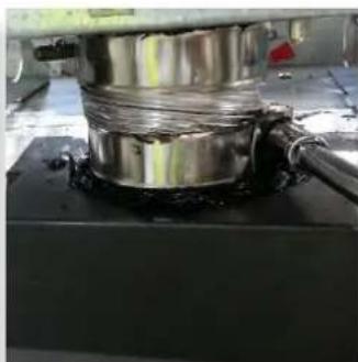
natural_image
Close-up of a metallic mechanical component mounted on a black base, no visible text or symbols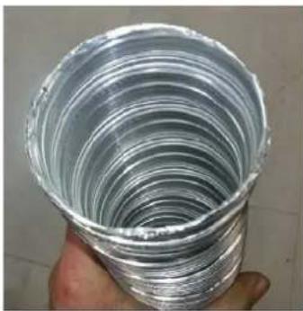
natural_image
Hand holding a transparent cylindrical object with concentric rings (no text or symbols visible)Fit hot exhaust flue pipe from outlet termination to fan outlet connection.
Cut tube to length where required.
Ensure ends are burr free and round, test fit flue will slide over connection.

natural_image
Close-up of a transparent cylindrical pipe with white insulation, being smoothed by a white tool (no text or symbols visible)Apply an 8mm thick silicon bead fully around heater connection approx. 10mm from the top.
Apply an 8mm silicon bead fully around the inside of the flue end (heater connection end)
Fit flue clamp over flue (loosely).

natural_image
Close-up of a metallic mechanical component with threaded end and bolted joints (no visible text or symbols)Slide flue onto connection spigot fully.
Tighten clamp fully.
Wipe excess silicon, visually check connection to ensure connection is fully sealed.

natural_image
Close-up of a mechanical pipe joint with a white tape, no visible text or symbolsConnect power lead to fan module. Ensure lead is clipped to support where required.
Do not use connection to support lead.

natural_image
Hand holding a transparent cylindrical object with concentric grooves (no text or symbols visible)Fit air intake flue pipe to heater connection.
Cut tube to length where required.
Ensure ends are burr free and round, test fit flue will slide over connection.

natural_image
Close-up of a metallic industrial pipe fitting with coiled tubing, mounted on a metal workbench (no visible text or symbols)Clip flues as required to provide adequate support.

natural_image
Close-up of a black cylindrical object with a white adhesive tape applied, no visible text or symbols.Apply an 8mm thick silicon bead fully around heater connection approx. 10mm from the top.
natural_image
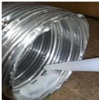
Close-up of a transparent cylindrical pipe with white insulation, being cut with a white tool (no text or symbols visible)Apply an 8mm silicon bead fully around the inside of the flue end (heater connection end)
Fit flue clamp over flue (loosely).
7. Connection to wall terminal
Loose fit connections (wall termination connections)


natural_image
Metallic rectangular object with rounded ends and a flat top, no visible text or symbols
natural_image
Close-up of a metallic threaded component with brass fittings and a coiled spring (no visible text or symbols)Slide flue onto connection spigot fully.
Tighten clamp fully.
Wipe excess silicon, visually check connection to ensure connection is fully sealed

natural_image
Two coiled metallic pipes with ribbed material, placed on a white rectangular base (no text or symbols visible)Locate terminal on wall and predrill mounting holes where required.
Cut flue exhaust tube (hot tube) to length (Flue must extend a minimum of 50mm past the exit face of wall.) It is recommended that the tubes are cut slightly longer and pushed back into wall upon fixing of wall terminal. Allow flue movement between terminal and last flue hanging clip.
Cut Air intake as per flue exhaust.
Ensure ends are burr free and round, test fit flue will slide inside both the hot exhaust connection and air intake connection.

natural_image
Close-up of a mechanical component with coiled metallic parts and a black housing (no visible text or symbols)Feed hot exhaust flue into connection, ensure inserted 50mm. Fit retaining screw from below.

natural_image
Close-up of a mechanical assembly with coiled metal wire and a metallic component (no visible text or symbols)Feed air intake flue into connection, ensure inserted 50mm. Fit retaining screw from below.

natural_image
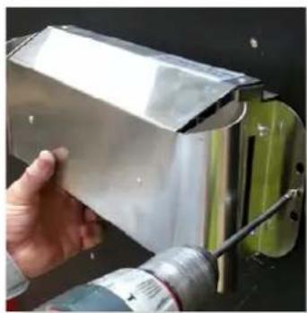
Metallic cylindrical mechanical component with coiled metal parts, no visible text or symbolsPush terminal into approximate position and affix onto wall.
natural_image
Hand holding a transparent plastic container next to a green industrial machine (no visible text or symbols)
natural_image
Metallic cylindrical object with yellow top, isolated on white background (no text or symbols)Fit flue exhaust insulation
Insulated with 25mm foil faces glasswool pipe insulation within 0.3m of each end of flue, as supplied by Glen Dimplex Australia.
Insulation must start as close to the gas space heater as possible
(Only exhaust flue is to be insulated)

natural_image
Close-up of a metallic pipe joint with reflective material, no visible text or symbolsInsulation to be fully closed and sealed along length.

natural_image
Close-up of a metallic pipe with wrapped insulation, mounted on a stand (no visible text or symbols)Bends were practical should be insulated, by cutting the insulation into segments and taping together.
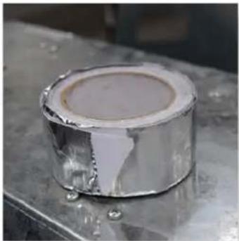
natural_image
Close-up of a metallic cylindrical object with reflective surface, no visible text or symbolsJoins can be taped together using aluminum foil self adhesive tape.

natural_image
Close-up of a metallic mechanical component with bolted joint and mounting holes (no visible text or symbols)Insulation must be fitted prior and after the inline powerflue fan.
Failure to fit insulation on the exhaust flue may result in condensation failures with the appliance.
Setup with internal fan module with wall termination - mid flue mounted
Maximum 10m flue length

natural_image
Technical line drawing of a ductwork or piping system mounted on a rectangular base (no text or symbols)Wall termination
- Wall terminal must be installed with clearances as specified by AS5601.1-2013 Clause 6.9.3
- Run exhaust flue and air intake flue as required - Maximum total run 10m per flue. Flues can be run next to each other. Maintain clearances to combustibles.
- Mount fan controller in the required location. (Access to the fan module is required for servicing, if the fan module is located inside a boxed frame, allow a 450 x 450 access panel).
- Connection to fan module to appliance run flue from appliance to bottom entry on fan module. Support flue with brackets as required.

natural_image
3D rendering of a mechanical sensor or camera mounted on a rail track (no text or symbols visible)5. Insulation Instructions-
Exhaust flue must be insulated using 25mm glass wool pipe insulation as supplied by Glen Dimplex Australia.
Insulation must be fitted to exhaust (hot side only).
Insulation must start as close to appliance as possible (within 300mm).
Insulation must finish as close to discharge as possible (within 300mm).
Insulation must run around bends.
Insulation to be taped to ensure no gaps.
Insulation may be fitted while running flue or at final stage of installation.
(shown at flue stage in Instructions)

natural_image
Hand holding a transparent cylindrical object with concentric grooves (no text or symbols visible)Cut tube to length where required.
Ensure ends are burr free and round, test fit flue will slide over connection.
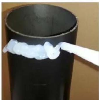
natural_image
Close-up of a black cylindrical object with a white adhesive tape applied, no visible text or symbolsApply an 8mm thick silicon bead fully around heater connection approx. 10mm from the top.

natural_image
Close-up of a transparent cylindrical pipe with white insulation, being smoothed by a white tool (no text or symbols visible)Apply an 8mm silicon bead fully around the inside of the flue end (heater connection end)
Fit flue clamp over flue (loosely).

natural_image
Close-up of a mechanical assembly with coiled metallic components and a brass fitting (no visible text or symbols)Slide flue onto connection spigot fully.
Tighten clamp fully.
Wipe excess silicon, visually check connection to ensure connection is fully sealed

natural_image
Close-up of a metallic mechanical assembly with mounting brackets and bolts (no visible text or symbols)Repeat for connection to underside of fan module.

natural_image
Close-up of a mechanical assembly with coiled spring and brass fittings (no visible text or symbols)Repeat for air intake flue connection.

natural_image
Hand holding a transparent cylindrical object with concentric rings (no text or symbols visible)Fan module outlet connection
Cut tube to length where required. Ensure ends are burr free and round, test fit flue will slide over connection.

natural_image
Close-up of a transparent cylindrical pipe with white insulation, being smoothed by a white tool (no text or symbols visible)Apply an 8mm thick silicon bead fully around heater connection approx. 10mm from the top.
Apply an 8mm silicon bead fully around the inside of the flue end (heater connection end)
Fit flue clamp over flue (loosely).
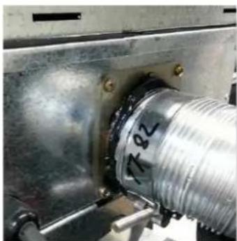
natural_image
Close-up of a metallic mechanical component with threaded end and bolted joints (no visible text or symbols)Slide flue onto connection spigot fully.
Tighten clamp fully.
Wipe excess silicon, visually check connection to ensure connection is fully sealed.

natural_image
Close-up of a mechanical pipe joint with a white adhesive tape, mounted on a metal frame (no visible text or symbols)- Connect power lead to fan module. Ensure lead is clipped to support where required.
Do not use connection to support lead.
Connection to wall terminal
Loose fit connections (wall termination connections)
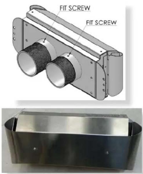
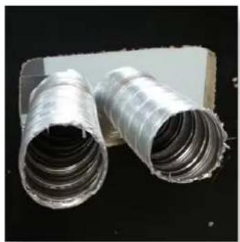
natural_image
Two coiled metallic pipes wrapped in plastic film, displayed against a black background (no text or symbols visible)Locate terminal on wall and predrill mounting holes where required.
Cut flue exhaust tube (hot tube) to length (Flue must extend a minimum of 50mm past the exit face of wall.) It is recommended that the tubes are cut slightly longer and pushed back into wall upon fixing of wall terminal. Allow flue movement between terminal and last flue hanging clip.
Cut Air intake as per flue exhaust.
Ensure ends are burr free and round, test fit flue will slide inside both the hot exhaust connection and air intake connection.

natural_image
Close-up of a mechanical device with rolled metal components and a black handle (no visible text or symbols)Feed hot exhaust flue into connection, ensure inserted 50mm. Fit retaining screw from below.

natural_image
Close-up of a mechanical assembly with coiled metal components and a green control box (no visible text or symbols)Feed air intake flue into connection, ensure inserted 50mm. Fit retaining screw from below.

natural_image
Metallic cylindrical object with yellow cap, isolated on white background (no text or symbols)Fit flue exhaust insulation
Insulated with 25mm foil faces glasswool pipe insulation within 0.3m of each end of flue, as supplied by Glen Dimplex Australia.
Insulation must start as close to the gas space heater as possible
(Only exhaust flue is to be insulated)
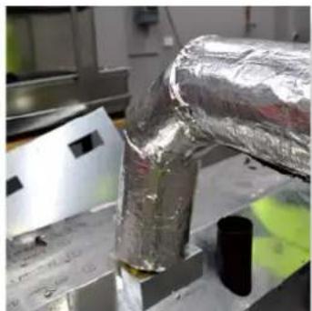
natural_image
Close-up of a metallic pipe joint with reflective material, no visible text or symbolsInsulation to be fully closed and sealed along length.
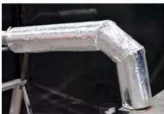
natural_image
Close-up of a metallic pipe with wrapped insulation, mounted on a stand (no visible text or symbols)Bends were practical should be insulated, by cutting the insulation into segments and taping together.

natural_image
Close-up of a metallic cylindrical object with reflective surface, no visible text or symbolsJoins can be taped together using aluminum foil self adhesive tape.
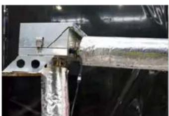
natural_image
Close-up of a metallic mechanical component with circular holes and a central shaft, no visible text or symbolsInsulation must be fitted prior and after the inline powerflue fan.
Failure to fit insulation on the exhaust flue may result in condensation failures with the appliance.
INTERNAL FAN & ROOF TERMINATION
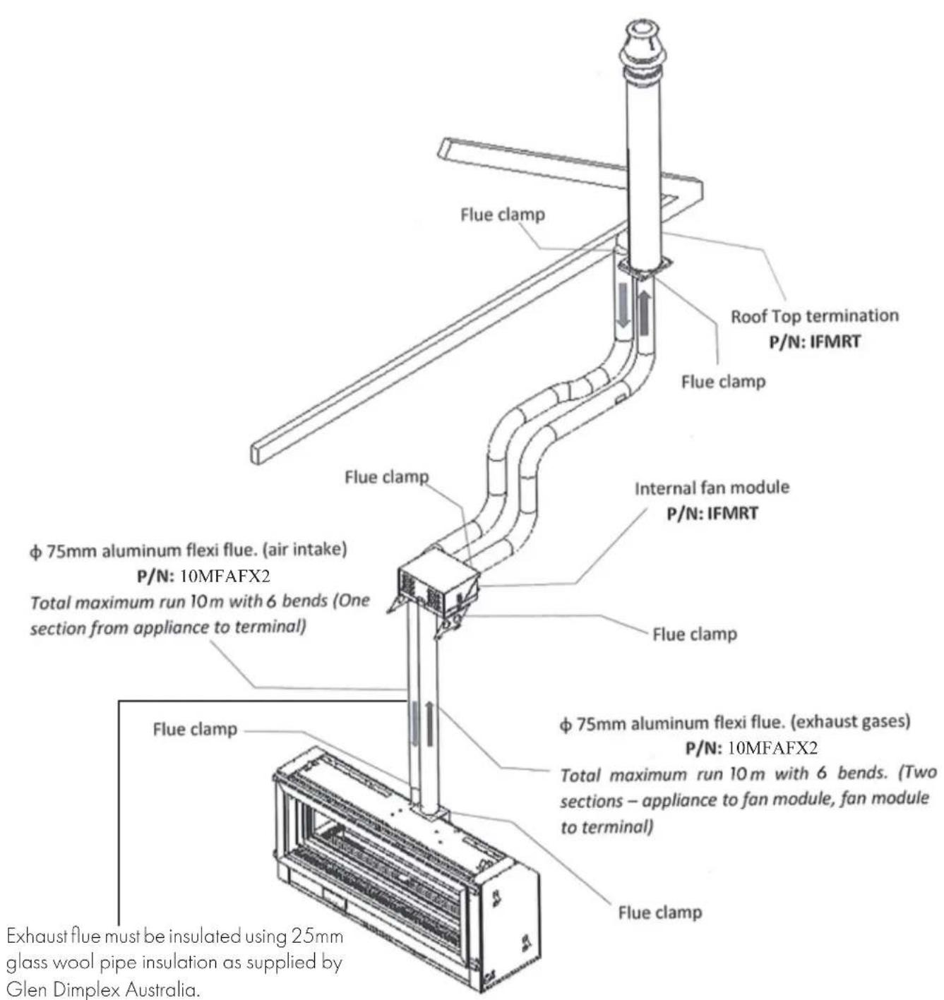
Exhaust flue must be insulated using 25mm glass wool pipe insulation as supplied by Glen Dimplex Australia.
Insulation must be fitted to exhaust (hot side only).
Insulation must start as close to appliance as possible (within 300mm).
Setup with internal fan module with rooftop termination - mid flue mounted
Maximum 10m flue length
Note- fan module can be appliance mounted or mid mounted when finishing with the rooftop termination.
Rooftop termination
- Rooftop termination must be installed with clearances as specified by AS5601.1-2013.
- Run exhaust flue and air intake flue as required - Maximum total run 10m per flue. Flues can be run next to each other. Maintain clearances to combustibles.
- Mount fan controller in the required location. (Access to the fan module is required for servicing, if the fan module is located inside a boxed frame, allow a 450 x 450 access panel).
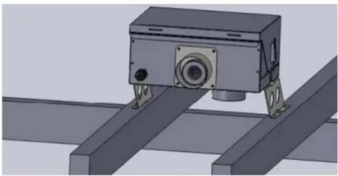
natural_image
3D rendering of a mechanical sensor or camera mounted on a rail track (no text or symbols visible)- Insulation Instructions-
Exhaust flue must be insulated using 25mm glass wool pipe insulation as supplied by Glen Dimplex Australia. Insulation must be fitted to exhaust (hot side only).
Insulation must start as close to appliance as possible (within 300mm).
Insulation must finish as close to discharge as possible (within 300mm).
Insulation must run around bends.
Insulation to be taped to ensure no gaps.
Insulation may be fitted while running flue or at final stage of installation.
(shown at flue stage in Instructions)

natural_image
Hand holding a transparent cylindrical object with concentric grooves (no text or symbols visible)Run flue from appliance to bottom entry on fan module.
Support flue with brackets as required
Cut flue to length to suit connection.
Ensure ends are burr free and round, test fit flue will fit over connection.
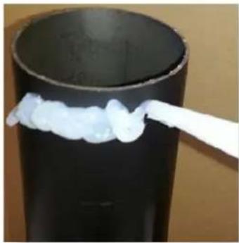
natural_image
Close-up of a black cylindrical container with a white adhesive tape applied, no visible text or symbolsApply an 8mm thick silicon bead fully around heater connection approx. 10mm from the top.
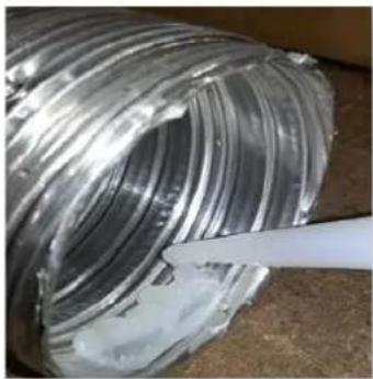
natural_image
Close-up of a transparent cylindrical pipe with white insulation, being smoothed by a white tool (no text or symbols visible)Apply an 8mm silicon bead fully around the inside of the flue end (heater connection end)
Fit flue clamp over flue (loosely).
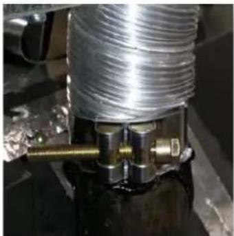
natural_image
Close-up of a mechanical assembly with coiled metallic tubing and a brass fitting (no visible text or symbols)Slide flue onto connection spigot fully.
Tighten clamp fully.
Wipe excess silicon, visually check connection to ensure connection is fully sealed
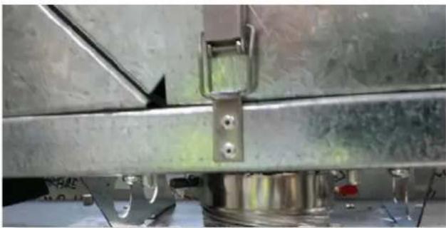
natural_image
Close-up of a metallic mechanical assembly with mounting brackets and bolts (no visible text or symbols)Repeat for connection to underside of fan module.

natural_image
Close-up of a mechanical assembly with coiled metal tubing and a brass fitting (no visible text or symbols)Repeat for air intake flue connection.

natural_image
Close-up of a hand holding a transparent cylindrical object with concentric rings (no text or symbols visible)- Fan module outlet connection
Cut tube to length where required.
Ensure ends are burr free and round, test fit flue will slide over connection.

natural_image
Close-up of a transparent cylindrical pipe with white insulation, being smoothed by a white tool (no text or symbols visible)Apply an 8mm thick silicon bead fully around heater connection approx. 10mm from the top.
Apply an 8mm silicon bead fully around the inside of the flue end (heater connection end)
Fit flue clamp over flue (loosely).
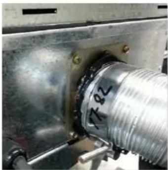
natural_image
Close-up of a metallic mechanical component with threaded shaft and flange (no visible text or symbols)Slide flue onto connection spigot fully.
Tighten clamp fully.
Wipe excess silicon, visually check connection to ensure connection is fully sealed.

natural_image
Close-up of a metallic pipe joint with a white tape, mounted on a metal frame (no visible text or symbols)- Connect power lead to fan module. Ensure lead is clipped to support where required.
Do not use connection to support lead.
6. Connection to rooftop terminal
Prepare roof penetration. Remove cowl from termination if fitted.

natural_image
3D technical illustration of a mechanical component with concentric cylindrical sections and mounting holes (no text or symbols)
natural_image
3D diagram of a mechanical component with layered structure (no text or symbols)Cut rooftop penetration to length if required.
Install in to roof penetration.
Install supports for base of penetration kit.

natural_image
Close-up of a transparent plastic coiled pipe with white insulation, being smoothed by a white tool (no text or symbols visible)Connect hot exhaust flue and air intake flue as per below.
Apply an 8mm silicon bead fully around the inside of the flue end
Fit flue clamp over flue (loosely).

Slide flue onto connection spigot fully.
Tighten clamp fully.
Wipe excess silicon, visually check connection to ensure connection is fully sealed.
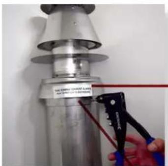
IMPORTANT- Apply silicon bead between inner connection of cowl and flue pipe to seal inner flue to cowl. Outer does not require sealing.
- Fit roof sealing method (Decktite or similar).
Ensure flue is supported and clipped where required.
Screw or rivet in 3 places to hold in place.

natural_image
Metallic cylindrical object with yellow top and black border, isolated on white background (no text or symbols)Fit flue exhaust insulation
Insulated with 25mm foil faces glasswool pipe insulation within 0.3m of each end of flue, as supplied by Glen Dimplex Australia.
Insulation must start as close to the gas space heater as possible
(Only exhaust flue is to be insulated)

natural_image
Close-up of a metallic pipe being compressed onto a workbench, no visible text or symbolsInsulation to be fully closed and sealed along length.

natural_image
Close-up of a metallic pipe with wrapped insulation, mounted on a stand (no visible text or symbols)Bends were practical should be insulated, by cutting the insulation into segments and taping together.

natural_image
Close-up of a metallic cylindrical object with reflective surface, no visible text or symbolsJoins can be taped together using aluminum foil self adhesive tape.

natural_image
Close-up of a metallic mechanical component with bolt holes and wiring (no visible text or symbols)Insulation must be fitted prior and after the inline powerflue fan.
Failure to fit insulation on the exhaust flue may result in condensation failures with the appliance.
ROOFTOP TERMINATION WITH EXTERNAL MOTOR
5 TO 10m FLUE RUN

Setup with external rooftop termination
Maximum 10m flue length
Rooftop termination
- Rooftop fan module – Terminal must be installed with clearances as specified by AS/NZS 5601.1 Clause 6.9.3
- Run exhaust flue and air intake flue as required
- Maximum run 10mts. Flues can be run next to each other. Maintain the required clearances to combustibles.
- Insulation Instructions-
Exhaust flue must be insulated using 25mm glass wool pipe insulation as supplied by Glen Dimplex Australia. Insulation must be fitted to exhaust (hot side only).
Insulation must start as close to appliance as possible (within 300mm).
Insulation must finish as close to discharge as possible (within 300mm).
Insulation must run around bends.
Insulation to be taped to ensure no gaps.
Insulation may be fitted while running flue or at final stage of installation.
(shown at flue stage in Instructions)

natural_image
Metallic cylindrical device with a red ring base, no visible text or symbols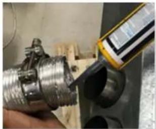
natural_image
Close-up of a hand holding a metallic mechanical component with a digital thermometer inserted (no visible text or symbols)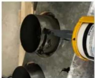
natural_image
Close-up of industrial pipe fittings and a yellow safety clip (no visible text or symbols)On the heater connection end - Fit clamp loosely & apply silicon inside the pipes. Apply an 8mm silicon bead fully around the inside of the flue and on the heater spigot. Smear the silicon around the spigot and pipe.
Recommended Silicon - Non-acetic, neutral cure 150°C or higher temperature rated. Bostik RTV 926 or similar.

natural_image
Close-up of industrial mechanical components including a coiled spring and flanged housing (no visible text or symbols)Slide flue onto connection spigot fully. Tighten clamp fully. Wipe excess silicon, visually check connection to ensure connection is fully sealed.
Repeat above with air intake flue pipe to heater connection.
Clip flues as required to provide adequate support.
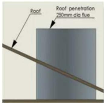
Insert the roof penetration and fix firmly to the roof structure using appropriate supports.
The roof penetration flue is a 250mm rigid flue.

Fit the access panel to the roof penetration.
Use the screw holes fix the access panel to the roof penetration.

natural_image
3D rendering of a mechanical component with cylindrical pipes mounted on a base (no text or symbols visible)Run flue pipes through the access cut outs before fitting the termination on for ease of installation.
(The picture is a reference only. Take care not to flex/bend the pipe too sharply and risk slitting the pipe)
If possible to insulate the flue pipe through the roof penetration, then fit insulation to the exhaust pipe.

Fit the termination on to the access panel and match the rivet holes to rivet the termination to the access panel.
Use only the rivets provided.

natural_image
Person pouring liquid from a bottle into a glass container using a spray can (no visible text or symbols)
natural_image
Close-up of a metallic mechanical component with internal threading and a red accent (no visible text or symbols)On the termination end - Fit clamp loosely & apply silicon inside the pipes. Apply an 8mm silicon bead fully around the inside of the flue and on the flue spigot. Smear smoothly around the surfaces.
Recommended Silicon – Non-acetic, neutral cure 200°C or higher temperature rated. Bostik RTV 922 or similar.
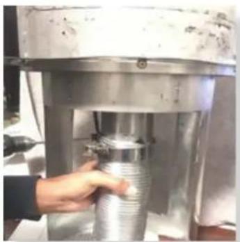
natural_image
Hand operating a cylindrical mechanical device with metallic components (no visible text or symbols)Slide flue onto connection spigot fully. Tighten clamp fully. Wipe excess silicon, visually check connection to ensure connection is fully sealed.
Ensure that the pipes are connected correctly and are not inverted.
Use the labels to identify exhaust and intake spigots

natural_image
Close-up of a metallic cylindrical device with coiled tubing and a red arrow pointing to a component (no visible text or symbols)Connect the fan power cable from the appliance to the termination.
Ensure the cable is clamped only to the intake pipe to secure the cable from hanging loose & touching the hot flue gases pipe.
Use the clamp provided. The clamp can be opened like a collar and fitted around on the flue.

natural_image
Metallic cylindrical object with yellow cap, isolated on white background (no text or symbols)Fit flue exhaust insulation
Insulated with 25mm foil faces glasswool pipe insulation within 0.3m of each end of flue, as supplied by Glen Dimplex Australia.
Insulation must start as close to the gas space heater as possible
(Only exhaust flue is to be insulated)
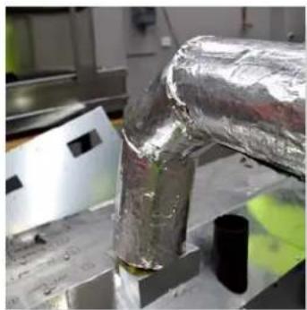
natural_image
Close-up of a metallic pipe with reflective material, no visible text or symbolsInsulation to be fully closed and sealed along length.

natural_image
Metallic duct-shaped pipe wrapped in plastic film, mounted on a stand against a black background (no text or symbols visible)Bends were practical should be insulated, by cutting the insulation into segments and taping together.

natural_image
Close-up of a metallic cylindrical object with reflective surface, no visible text or symbolsJoins can be taped together using aluminum foil self adhesive tape.

natural_image
Close-up of a metallic mechanical component with bolt holes and a central shaft (no visible text or symbols)Insulation must be fitted prior and after the inline powerflue fan.
Failure to fit insulation on the exhaust flue may result in condensation failures with the appliance.

natural_image
Close-up of hands installing or adjusting a metallic cylindrical component (no visible text or symbols)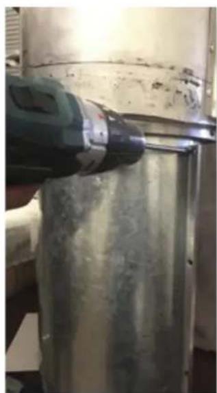
natural_image
Close-up of a metal cylindrical container being handled with a green drill bit, no visible text or symbolsFlex collar and fit around the access panel. Socket the collar all the way up close to the air intake slots Ensure there is a rubber seal top and bottom of the collar.
Use only the screws provided to tightly fit the collar to seal the access panel.
10-13.5M
POLYPROPYLENE FLUE CONFIGURATION
INSTALLATION INSTRUCTIONS
LOCATION
Select a location where the fire can be supervised during operation. An electrical isolation switch must be fitted at the appliance or on an adjacent wall to allow for emergency shutdown and maintenance. Installation must meet Australian gas codes AS5601
INSTALLATION CLEARANCES
Clearances from combustible materials
| Floor | 0mm | |
| Sides | 25mm | |
| Top | 25mm | |
| Flue outer | 25mm | |
| Front | 25mm | |
| Back | 25mm |
Note: Once installed no combustible items should be placed within 600mm of the fire viewing window.

GAS CONNECTION 15mm (1/2") Compression union ELECTRICAL CONNECTION 3 Pin 10 Amp GPO plug POWER RATING OF APPLIANCE 230V 50Hz 0.55 Amp
INSTALLATION CODES
Note appliance gas type - Natural gas/LPG/ULPG. Should the appliance be the incorrect gas type, please contact the supplier for conversion details.
Installers – Please ensure the installation and instruction manuals supplied with this appliance are supplied to the customer and the customer is trained on how to operate the appliance correctly.
Do not exceed maximum rated pressures.
Appliance must be installed with gas installation code (AS/NZS5601.1-2013) and applicable electrical installation code (AS3000).
Test for gas leaks prior to operating appliance.
Check gas pressures and adjust if incorrect.
FLUE CONFIGURATIONS
0-5m- Aluminum flexi flue as per 0-5m IOM.
5-10m- Aluminum flexi flue insulated. Refer to 5-10m insulated flue run IOM.
10-13.5m- Poly flue system. Refer to 10-13.5m flue configuration.
Where lengths greater than 5m are required the inlet is run completely in aluminum flexible flue, the first 5m of the outlet flue is run in flexible aluminum flue, then a poly flue system is used that requires drainage points to waste for condensation removal. – Note drain fall direction is different for rooftop flues. – Refer 10-13.5m Rooftop instruction.
Aluminum flue connections must be sealed with a suitable sealant.
Recommended Silicon - Non-acetic, neutral cure 150deg or higher temperature rated.
Bostik RTV 926 or similar
Run air intake flue as required – Maximum run 14m. Flues can be run next to each other.
Maintain clearances to combustibles.
This section is used to determine where your flue termination will be located.
- Flue terminations shall not be recessed in walls or sidings.
- EXTREMELY IMPORTANT: In heavy snow areas take extra care to prevent blocking flue termination with snow removal equipment.
- Flue gases exiting flue terminals are very hot and must not be restricted to assure fireplace combustion is not affected.
- Do not place, build any obstruction, plant any bushes or for any reason attempt to conceal the flue termination. To do so will affect the operation of the fireplace and may be hazardous.
• This unit must always vent directly to outdoors.
Condensate Disposal
Where possible the condensate drainage pipe should terminate at a suitable foul water discharge point, eg. waste drain point washing machine waste point etc.
The HepVO waterless trap should be installed where access can be maintained.
A P-trap can be used as an option instead of the HepVo waterless trap.
Do not discharge condensate onto walkways, electrical connections, earth stakes, copper pipes, waterways, ponds etc.
POLY PRO GENERAL INSTALLATION REQUIREMENTS
Refer to specific setups for detailed installation guides.

WARNING
CARBON MONOXIDE POISONING HAZARD. Failure to follow the steps outlined below for each appliance connected to the venting system being placed into operation could result in carbon monoxide poisoning or death.

WARNING
Risk of carbon monoxide poisoning or fire due to joint separation or pipe breakage.
Poly Pro flue systems meets Flame spread/ Smoke ratings <25/<50 (per UL-723 ASTM E-84 and ULC-S102) when used in conjunction with the below noted materials.
• 3m Fire barrier Plenum wrap 5A+
• Unifrax FyreWrap 0.5 Plenum insulation
- Knauf Insulation – Atmosphere Duct wrap with ECOSE Use soapy water to lubricate gaskets and tubes.
DO NOT USE petroleum based lubricants.
Joint Connections
Verify the gasket is seated evenly inside the groove in the female end. For PP/Metal pipe with a locking tab, slide locking band on male pipe section. Insert locking tab into locking band recess, rotate button away from locking band clasp, insert pipe sections, push lock band clamp downward into socket, disengage socket/tab 1/4" - 5/8" from socket. Screws are not allowed for joint connection. Never penetrate the wall of PolyPro vent pipe.
(Exception - a SS screw may be used outside the building on exterior termination fittings to orient an elbow, etc.)
IMPORTANT: Locking bands are mandatory on all exhaust vent joints.

Installation
-
Pipe lengths may be cut to length. Use an alternative clamp (PPS-PAC/PPS-LBC) for the connection if a locking tab is removed.
-
Cut square (not an angle) to the end of the pipe.
- Remove burrs before assembly.

- Check with appliance manufacturer for any restrictions or limits on vent length, number of elbows, etc.
- The slope of the vent pipe must be at least 3^ (50mm per meter) back to the appliance.
- Every horizontal section must be supported.
- The venting system shall be securely supported using suitable hangers. Duravent hardware is recommended; field supplied support hardware suitable to the AHJ is acceptable, hardware must not deform on damage the vent. Make sure the load on the vent system is not supported by the appliance. On
Duravent and other certain clamp styles, 1/4" or greater All-thread may be used as an extension.
- Vertical installations must be supported every 3 meters or less.
- Elbows and tees are sufficiently supported when a bracket is fixed at the female end of the connected straight section.
Vertical Concentric
- Locate penetration.
- Cut hole in roof.
- Cut hole in ceiling above appliance.
Cut hole(s) big enough for pipe in all ceilings above appliance if installing in a multi storey installation.
- Firestop each ceiling penetration.
- Attach flashing to roof.
Slide storm collar onto flashing if using the adjustable roof flashing.
- Slide vertical termination into flashing from above until seated on flashing.
- Plumb termination and mount support bracket to structure.


SETUP WITH EXTERNAL WALL MOUNTED FAN TERMINAL
Maximum 13.5m flue length
Instructions are in 3 sections
- Intake pipe connection
- Flue exhaust connections
- Wall mount controller setup

Wall mounted fan terminal

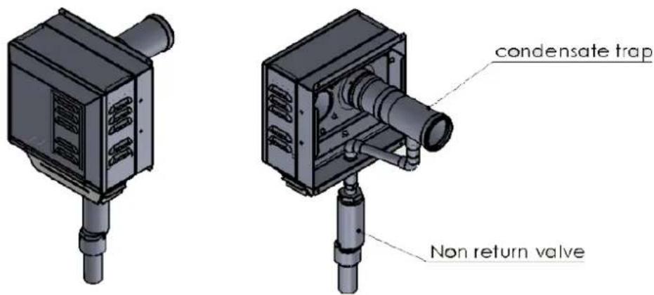
IMPORTANT INSTALLATION NOTES
- Flexi flue must be fully extended to length. 5m for exhaust flue and 2 x 7m for inlet.
- 5m of flexi flue on the exhaust side MUST be used before prior to converting to polypropylene.
Failure to do this will result in appliance shutdown.
INTAKE PIPE CONNECTION TO APPLIANCE

natural_image
Close-up of a hand holding a transparent cylindrical object with concentric grooves (no text or symbols visible)Flexi flue is provided for air intake. A maximum of 2 x 7m lengths can be used.
Cut tube to length where required.
Ensure ends are burr free and round, test fit flue will slide over connection.

natural_image
Close-up of a black cylindrical container with a white adhesive tape applied to its side (no text or symbols visible)Recommended Silicon - Non-acetic, neutral cure 150°C or higher temperature rated.
Bostik RTV 926 or similar.
Apply an 8mm thick silicon bead fully around heater connection approx. 10mm from the top.

natural_image
Close-up of a transparent cylindrical pipe with white insulation, being smoothed by a tool (no text or symbols visible)Apply an 8mm silicon bead fully around the inside of the flue end (heater connection end)
Fit flue clamp over flue (loosely).
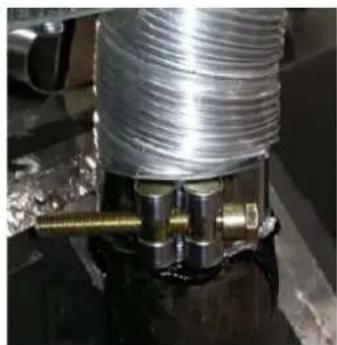
natural_image
Close-up of a mechanical assembly with coiled transparent tubing and a metallic fitting (no visible text or symbols)Slide flue onto connection spigot fully.
Tighten clamp fully.
Wipe excess silicon, visually check connection to ensure connection is fully sealed
Intake pipe joiner connection

natural_image
Close-up of metallic pipe fittings and circular components on a metal surface (no text or symbols visible)
natural_image
Hand holding a transparent plastic cylindrical object with concentric grooves (no text or symbols visible)Ensure ends are burr free and round, test fit flue will slide over connection joiner.

natural_image
Three coiled metal pipes with insulation, one open showing internal structure (no text or symbols visible)Apply an 8mm thick silicon bead fully around both ends of connector approx. 10mm from the ends.

natural_image
Close-up of a transparent cylindrical pipe with white insulation, being cut with a white tool (no text or symbols visible)Apply an 8mm silicon bead fully around the inside of the flue end
Fit flue clamp over flue (loosely).

natural_image
Close-up of a coiled metal pipe with attached electrical connectors (no visible text or symbols)Slide each flue halfway onto connection joiner.
Tighten clamp fully.
Wipe excess silicon, visually check connection to ensure connection is fully sealed.
Intake connection to wall mounted fan terminal
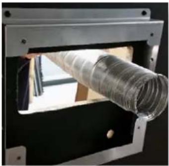
natural_image
Close-up of a mechanical component with a coiled metallic pipe inserted into a black frame (no visible text or symbols)Cut air intake flue to length (Approximately 70mm through wall exit).
Connection plate will sit against wall.

natural_image
Close-up of a hand holding a metallic mechanical component with a transparent cylindrical housing (no visible text or symbols)Ensure ends are burr free and round, test fit flue will slide over connection.
Feed air intake flue pipe through location spigot and fit retaining screw.
Push connection plate into approximate position.

natural_image
Close-up of a metallic mechanical device with a coiled cable or sensor attached, no visible text or symbols.Locate wall mounting bracket into position and affix to wall.

natural_image
Close-up of a metallic mechanical device with a circular aperture and cylindrical lens (no visible text or symbols)Assemble spigot connection plate assembly to wall mounting bracket. (4 screws)
OUTLET CONNECTION FROM HEATER
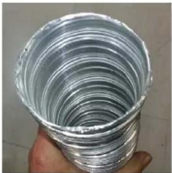
natural_image
Hand holding a transparent plastic cylindrical container with concentric rings (no text or symbols visible)Note: The full 5m of flexi flue must be used.
Fully extend the 5m aluminum flexi flue.
NOTE- FULL LENGTH MUST BE USED.
Ensure ends are burr free and round, test fit flue will slide over connection.

natural_image
Close-up of a black cylindrical object with a white adhesive tape applied, no visible text or symbolsApply an 8mm thick silicon bead fully around heater connection approx. 10mm from the top.

natural_image
Close-up of a transparent cylindrical pipe with white insulation, partially covered by a white plastic clip (no text or symbols visible)Apply an 8mm silicon bead fully around the inside of the flue end (heater connection end)
Fit flue clamp over flue (loosely).

natural_image
Close-up of a mechanical assembly with coiled metallic tubing and a brass fitting (no visible text or symbols)Slide flue onto connection spigot fully.
Tighten clamp fully.
Wipe excess silicon, visually check connection to ensure connection is fully sealed
Aluminum to Poly Pro flue connection

natural_image
3D rendering of a mechanical pipe fitting with three black connectors (no text or symbols visible)Note: A total of 5m of aluminum flexi flue must be used prior to the joiner. Failure to do this will result in appliance shutdown.
![ALUMINIUM TO POLY PRO JOINER FLUE PIPE 75mm ALUMINIUM FLEXIBLE FLUE RUN 5m WITH UPTO 4 BENDS [SUPPLIED IN 5m LENGTH - NOTE FULL 3m LENGTH MUST BE USED] POLY PRO FLUE PIPE 80MM DIA MAX RUN 8.5M WITH 5 BENDS NOTE - DRAINAGE FALL TOWARDS FAN MODULE AT FLUE END](/content/2026/05/1058562/images/a6635742755adcd18c854efac971ff62893ad85e5226d50e9dc9e54da7db12eb.jpg)

natural_image
Close-up of a metallic cylindrical object with reflective surface, possibly a mechanical component or mold (no visible text or symbols)Apply sealant to flue inner and connector.

natural_image
Close-up of a transparent cylindrical pipe with white insulation, being smoothed by a white tool (no text or symbols visible)Apply sealant to flue inner and connector.
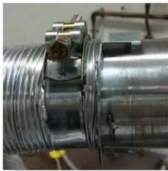
natural_image
Close-up of a metallic mechanical component with threaded end and flange (no visible text or symbols)Fit flue clamp over flue (loosely).
Slide flue onto connection spigot fully.
Tighten clamp fully.
Wipe excess silicon, visually check connection to ensure connection is fully sealed.

natural_image
Close-up of a metallic cylindrical device with attached electrical connector and cable, no visible text or symbols on the main body.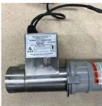
Lubricate the Poly pro with water or soapy water.
Slide the poly onto the joiner connection.
Run Poly to wall mount fan.
Poly Pro to Poly Pro flue connection
Verify gasket is sitting correctly.
Apply a light soapy water film to the gasket and tube end. Insert pipe fully into end fitting, Pipe will push in smoothly and evenly, should this not occur remove pipe and reset gasket. Reapply light soapy film to ensure easy fit.
Rotate clip so catch is opposite the location tab
Clip catch into place to prevent flue pipes from separating.
Ensure pipes are clipped adequately.
Ensure a minimum of 3deg fall occurs towards the drain end.


natural_image
Close-up of a white plastic container with a black lid, partially visible against a light background (no text or symbols)
natural_image
Close-up of a white cylindrical mechanical component with a visible crack and label (no readable text or symbols)Installation
- Pipe lengths may be cut to length. Use an alternative clamp (PPS-PAC/PPS-LBC) for the connection if a locking tab is removed.
- Cut square (not an angle) to the end of the pipe.
- Remove burrs before assembly.
-
Check with appliance manufacturer for any restrictions or limits on vent length, number of elbows, etc.
-
The slope of the vent pipe must be at least 3^ (50mm per meter) back to the appliance.
-
Every horizontal section must be supported.

Poly Pro to wall mounted fan module connection
Ensure mounting plate is affixed to wall bracket.
Verify gasket is sitting correctly in condensate drain connection.
Apply a light soapy water film to the gasket and the tube end.
Insert pipe fully into end fitting, Pipe will push in smoothly and evenly, should this not occur remove pipe and reset gasket. Reapply light soapy film to ensure easy fit. Tighten hose clamp to restrain flue in place.

natural_image
Close-up of industrial hoses and pipes in a storage or inspection setting (no visible text or symbols)Wall Mounted Fan Module Setup
Wall mounted fan module - terminal must be installed with clearances as specified by AS5601.1, Clause 6.9.3.
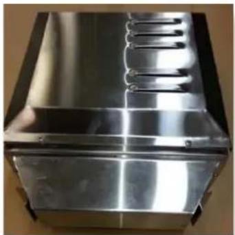
natural_image
Metallic stainless steel container with ribbed top and side slots (no text or symbols visible)Remove cover from fan terminal
Remove main assembly from the rear wall mounting plate assembly.
Remove the 5 screws as shown. (Do not remove fan plate screws)
Lift off main fan terminal assembly.

natural_image
Interior view of an open metallic enclosure with visible internal components and wiring (no text or symbols)
natural_image
Close-up of a metallic mechanical device with cylindrical and threaded components (no visible text or symbols)Assemble spigot connection plate assembly to wall mounting bracket. (4 screws)
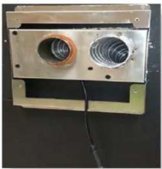
natural_image
Metallic industrial housing with two circular openings and a coiled cable, no visible text or symbolsFeed power cable through bottom area of bracket.

natural_image
Metallic mechanical housing with two circular cavities and bolt holes (no text or symbols visible)Remove wall mount plate from flue connection plate.

natural_image
Close-up of a hand holding a metallic mechanical component with a coiled plastic tube (no visible text or symbols)Push connection plate into approximate position.
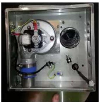
natural_image
Interior view of an open industrial control box with visible wiring, components, and wiring harness (no text or symbols)Assemble main body assembly onto wall mounting bracket, feed power cable through grommet hole prior to fitting. (refit 5 screws as shown and tighten) Main body assembly must sit flush up against the mounting bracket and seal.

natural_image
Close-up of a metallic mechanical device with two circular components and a connecting rod (no visible text or symbols)Locate wall mounting bracket into position and affix to wall.

natural_image
Hand using a screwdriver to adjust or install a coiled spring component inside an open electrical box (no visible text or symbols)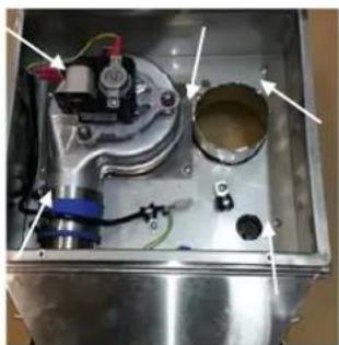
natural_image
Interior view of a metallic industrial or laboratory equipment housing with visible components and wiring (no text or symbols)
natural_image
Close-up of a hand using a tool to adjust or install electronic components (no visible text or symbols)Connect power cable connector.
Fit cable clamp to cable.

natural_image
Metallic industrial or laboratory equipment with three side slots and a central handle (no visible text or symbols)Fit front cover.
SETUP WITH APPLIANCE MOUNTED FAN OR INLINE MOUNTED FAN AND WALL TERMINAL
Maximum 13.5m flue length
Instructions are in 3 sections
- Intake pipe connection
- Flue exhaust connections
- Wall terminal setup

NOTE - A MINIMUM OF 3 DEG. DRAINAGE FALL MUST BE INSTALLED IN THE POLY PROFLUE. DRAINAGE DIRECTION IS TOWARDS THE WALL TERMINAL AT THE END OF THE FLUE.


IMPORTANT INSTALLATION NOTES
Flexi flue must be fully extended to length. 5m for exhaust flue and 2 x 7m for inlet.
5m of flexi flue on the exhaust side MUST be used before prior to converting to polypropylene. Failure to do this will result in appliance shutdown.
Air intake pipe - Intake pipe connection to appliance

natural_image
Close-up of a hand holding a transparent plastic cylindrical container with concentric grooves (no text or symbols visible)Cut flue to length to suit connection.
Ensure ends are burr free and round, test fit flue will fit over connection.
Recommended Silicon – Non-acetic, neutral cure 150°C or higher temperature rated.
Bostik RTV 926 or similar.

natural_image
Close-up of a black cylindrical container with a white adhesive tape attached to its side (no text or symbols visible)Apply an 8mm thick silicon bead fully around heater connection approx. 10mm from the top.

natural_image
Close-up of a transparent cylindrical pipe with white insulation, being smoothed by a white tool (no text or symbols visible)Flexi flue is in 7m lengths. A maximum of 2 lengths can be used.
Apply an 8mm silicon bead fully around the inside of the flue end (heater connection end) Fit flue clamp over flue (loosely).

natural_image
Close-up of a metallic mechanical component with threaded spring and brass fittings (no visible text or symbols)Slide flue onto connection spigot fully.
Tighten clamp fully.
Wipe excess silicon, visually check connection to ensure connection is fully sealed
Air intake pipe - Intake pipe joiner connection

natural_image
Close-up of metallic pipe fittings and metal rings on a wooden surface (no text or symbols visible)
natural_image
Hand holding a transparent cylindrical metal pipe with concentric grooves (no text or symbols visible)Ensure ends are burr free and round, test fit flue will slide over connection joiner.

natural_image
Three cylindrical metal pipes with plastic wrap, one open showing a greenish liquid, placed on a textured surface (no text or symbols visible)Apply an 8mm thick silicon bead fully around both ends of connector approx. 10mm from the ends.

natural_image
Close-up of a transparent cylindrical pipe with white insulation being inserted, no visible text or symbolsApply an 8mm silicon bead fully around the inside of the flue end
Fit flue clamp over flue (loosely).
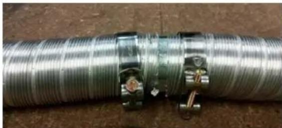
natural_image
Close-up of a coiled metal pipe with attached clamps and fittings (no visible text or symbols)Slide each flue halfway onto connection joiner.
Tighten clamp fully.
Wipe excess silicon, visually check connection to ensure connection is fully sealed.
Air intake pipe - Intake connection to wall mounted fan terminal

natural_image
3D rendering of a metal enclosure or housing component with mounting flanges and bolt holes (no text or symbols visible)Locate terminal on wall and pre-drill mounting holes where required.
Cut flue inlet tube to length (Flue must extend a minimum of 50mm past the exit face of wall.) It is recommended that the tubes are cut slightly longer and pushed back into wall upon fixing of wall terminal. Allow flue movement between terminal and last flue hanging clip.
Ensure ends are burr free and round, test fit flue will slide inside both the hot exhaust connection and air intake connection.
Feed air intake flue into connection, ensure inserted 50mm. Fit retaining screw from below.
Push terminal into approximate position and affix onto wall.
Flue Exhaust Connections - Connection to fan module at appliance

natural_image
Hand holding a transparent cylindrical object with concentric grooves (no text or symbols visible)Check flue piece for correct shape and fitment onto appliance spigot.
FOR DIRECT MOUNT CUT 65MM - Otherwise cut the required length.
Ensure ends are burr free and round, test fit flue will slide over connection.
Recommended Silicon - Non-acetic, neutral cure 150degc or higher temperature rated.
Bostik RTV 926 or similar.
Apply an 8mm thick silicon bead fully around heater connection approx. 10mm from the top.
Apply an 8mm thick silicon bead fully around the lower fan connection spigot approx. 10mm from the end.

natural_image
Close-up of a black cylindrical container with a white plastic film being inserted into it (no text or symbols visible)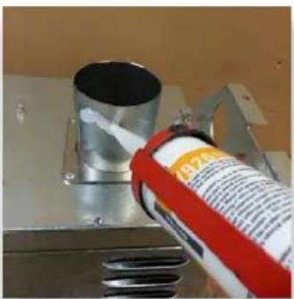
natural_image
Close-up of a red spray caner applying white paint to a metal cylindrical container on a metal workbench (no visible text or symbols)
natural_image
Close-up of a coiled metallic pipe with a white plastic tube inserted, placed on a wooden surface (no text or symbols visible)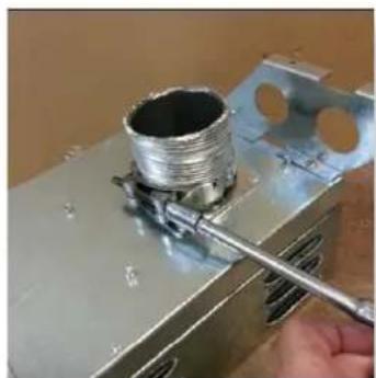
natural_image
Close-up of a hand using a tool to adjust a metallic component with threaded end (no visible text or symbols)Turn fan assembly upside down and slide 65mm flue section fully onto spigot.
Fit flue clamp and tighten clamp fully.
Wipe excess silicon, visually check connection to ensure connection is fully sealed.

natural_image
Close-up of a metallic mechanical component with a pipe inserted, no visible text or symbols(Note 90° left connection is not available and must be done using the 90° right connection fan location and placing a bend in the flue to head in the LH direction.
Fit 2nd flue clamp loosely onto the 65mm section of flue.
Lift fan assembly into appliance and locate onto flue connection. Insert fully. Locate fan in the required direction. Screw fan assembly down onto the appliance. (Screws prefitted into holes are located on the appliance for direct out back connection and 90° to right connection.)
Locate 2nd clamp onto lower connection and tighten clamp fully.
Wipe excess silicon, visually check connection to ensure connection is fully sealed.

natural_image
Close-up of a metallic mechanical component mounted on a workbench, no visible text or symbols
natural_image
Close-up of a metallic mechanical component mounted on a black base, no visible text or symbolsWhere fan sits higher, ensure fan assembly is supported on a frame. Where timber framing is used clearances to flue and fan box must be maintained.
Flue Exhaust Connections - Fit hot exhaust flue pipe from outlet termination to fan outlet connection
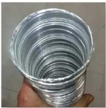
natural_image
Hand holding a transparent plastic cylindrical container filled with concentric rings (no text or symbols visible)Cut flue to length to suit connection. Ensure ends are burr free and round, test fit flue will fit over connection.
5m of flexi flue on the exhaust side MUST be used before prior to converting to polypropylene. Failure to do this will result in appliance shutdown.
![ALUMINIUM TO POLY PRO JOINER FLUE PIPE 75mm ALUMINIUM FLEXIBLE FLUE RUN 5m WITH UPTO 4 BENDS [SUPPLIED IN 5m LENGTH - NOTE FULL 5m LENGTH MUST BE USED] POLY PRO FLUE PIPE 80MM DIA MAX RUN 8.5M WITH 5 BENDS NOTE - DRAINAGE FALL TOWARDS FAN MODULE AT FLUE END](/content/2026/05/1058562/images/86d49c1238719911706ec4b0b3c64859ab549b0af7d85d7c7755e3076793efbc.jpg)

natural_image
Close-up of a coiled plastic pipe with a white plastic clip inserted, showing internal structure (no text or symbols visible)Apply an 8mm thick silicon bead fully around heater connection approx. 10mm from the top.
Apply an 8mm silicon bead fully around the inside of the flue end (heater connection end)
Fit flue clamp over flue (loosely).

natural_image
Close-up of a metallic mechanical component with threaded shaft and flange (no visible text or symbols)Slide flue onto connection spigot fully.
Tighten clamp fully.
Wipe excess silicon, visually check connection to ensure connection is fully sealed.

natural_image
Close-up of a mechanical component with metallic parts and a white tape, no visible text or symbolsConnect power lead to fan module. Ensure lead is clipped to support where required.
Do not use connection to support lead.
Flue Exhaust Connections - Aluminum to Poly Pro flue connection

natural_image
3D rendering of a mechanical pipe fitting with two connectors (no text or symbols visible)Ensure ends are burr free and round, test fit flue will fit over connection.
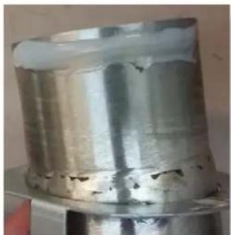
natural_image
Close-up of a metallic cylindrical object with reflective surface, possibly a mechanical component or sensor (no visible text or symbols)Apply sealant to flue inner and connector.

natural_image
Close-up of a metallic mechanical component with flanged ends and bolted joints (no visible text or symbols)Fit flue clamp over flue (loosely).
Slide flue onto connection spigot fully.
Tighten clamp fully.
Wipe excess silicon, visually check connection to ensure connection is fully sealed.
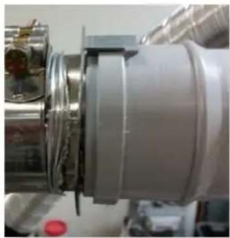
natural_image
Close-up of a mechanical component with metallic parts and a gray cylindrical body (no visible text or symbols)Apply soapy water to ring in Poly Pro flue and dampen surface of connector.
Push connector fully into Poly pro end connection.
Push both clips over to lock into place.

natural_image
Close-up of a metallic cylindrical device with attached black cable and warning label (no readable text or symbols on the device itself)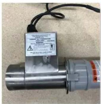
Lubricate the Poly pro with water or soapy water.
Slide the poly onto the joiner connection.
Run Poly to wall mount fan.
Poly Pro to Poly Pro flue connection
Verify gasket is sitting correctly.
Apply a light soapy water film to the gasket and tube end. Insert pipe fully into end fitting, Pipe will push in smoothly and evenly, should this not occur remove pipe and reset gasket. Reapply light soapy film to ensure easy fit.
Rotate clip so catch is opposite the location tab
Clip catch into place to prevent flue pipes from separating.
Ensure pipes are clipped adequately.
Ensure a minimum of 3deg fall occurs towards the drain end.

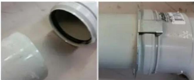
natural_image
Two views of a white PVC pipe fitting, one showing a circular opening and the other showing a cylindrical component with a label (no visible text or symbols)Installation
- Pipe lengths may be cut to length. Use an alternative clamp (PPS-PAC/PPS-LBC) for the connection if a locking tab is removed.
- Cut square (not an angle) to the end of the pipe.
- Remove burrs before assembly.
-
Check with appliance manufacturer for any restrictions or limits on vent length, number of elbows, etc.
-
The slope of the vent pipe must be at least 3^ (50mm per meter) back to the appliance.
-
Every horizontal section must be supported.

Poly Pro to Wall mounted terminal
Ensure terminal is affixed to the wall.
Verify gasket is sitting correctly in condensate drain connection.
Apply a light soapy water film to the gasket and the tube end.
Insert pipe fully into end fitting, Pipe will push in smoothly and evenly, should this not occur remove pipe and reset gasket. Reapply light soapy film to ensure easy fit.
Tighten hose clamp to restrain flue in place.

natural_image
3D rendering of a mechanical housing component with mounting holes and internal ribs (no text or symbols)Locate terminal on wall and pre-drill mounting holes where required.
Mark out the required penetration area. Cutout the area in wall for the flue pipes and condensate drain.
(NOTE - Access to rear of terminal may be required to assemble flue) Where access is not available a single large cutout is required for the flues and the condensate drain.

natural_image
3D rendering of a mechanical sensor or camera module with cylindrical ports and connecting pipes (no text or symbols visible)
Cut inlet air tube. Flue must extend a minimum of 50mm past the exit face of wall.) It is recommended that the intake tube is cut slightly longer and pushed back into wall upon fixing of wall terminal. Allow flue movement between terminal and last intake flue hanging clip.
Attach intake flue using the self tapping screw.
Ensure condensate drain retaining clamp is tight.
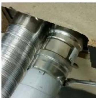
natural_image
Close-up of a metallic mechanical component with threaded ends and a curved pipe (no visible text or symbols)Push terminal into approximate position and affix onto wall
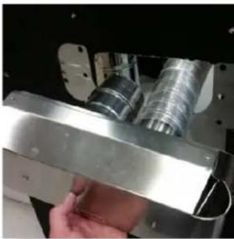
natural_image
Close-up of a hand holding a metallic mechanical component with coiled tubing (no visible text or symbols)Assemble condensate drain and attach to pipe exiting wall. PVC pressure pipe cement must be used.
40mm PVC pipe must be fitted (not shown) to drain to waste
Components supplied loose.

natural_image
White PVC water dispenser with red spray lines on a textured surface (no text or symbols visible)15mm PVC Elbow or 15mm STRAIGHT CONNECTOR
15mm PVC class 18 tube
15mm PVC to 15mm threaded union
15mm to 20mm union
20mm to 40mm union
40mm non-return valve
WIRING - FLUE TEMPERATURE LIMITING DEVICE
The flue temperature limiting device is inbuilt into the extension wiring and the flue adapter.
The connection directly connects to the loom from the appliance. The other end directly connects to the fan module.
Connections are not interchangeable.
The temperature limiting is preset and does not require adjustment.
10-13.5M ROOFTOP POLYPROPYLENE FLUE CONFIGURATION
INSTALLATION INSTRUCTIONS
LOCATION
Select a location where the fire can be supervised during operation. An electrical isolation switch must be fitted at the appliance or on an adjacent wall to allow for emergency shutdown and maintenance. Installation must meet Australian gas codes AS5601
INSTALLATION CLEARANCES
Clearances from combustible materials
| Floor | 0mm | |
| Sides | 25mm | |
| Top | 25mm | |
| Flue outer | 25mm | |
| Front | 25mm | |
| Back | 25mm |
Note: Once installed no combustible items should be placed within 600mm of the fire viewing window.

GAS CONNECTION 15mm (1/2") Compression union ELECTRICAL CONNECTION 3 Pin 10 Amp GPO plug POWER RATING OF APPLIANCE 230V 50Hz 0.55 Amp
INSTALLATION CODES
Note appliance gas type – Natural gas/LPG/ULPG. Should the appliance be the incorrect gas type, please contact the supplier for conversion details.
Installers – Please ensure the installation and instruction manuals supplied with this appliance are supplied to the customer and the customer is trained on how to operate the appliance correctly.
Do not exceed maximum rated pressures.
Appliance must be installed with gas installation code (AS/NZS5601.1-2013) and applicable electrical installation code (AS3000).
Test for gas leaks prior to operating appliance.
Check gas pressures and adjust if incorrect.
FLUE CONFIGURATIONS
0-5m- Aluminum flexi flue as per 0-5m IOM.
5-10m- Aluminum flexi flue insulated. Refer to 5-10m insulated flue run IOM.
10-13.5m- Poly flue system. Refer to 10-13.5m flue configuration.
Where lengths greater than 5m are required the inlet is run completely in aluminum flexible flue, the first 5m of the outlet flue is run in flexible aluminum flue, then a poly flue system is used that requires drainage points to waste for condensation removal. – Note drain fall direction is different for rooftop flues. – Refer 10-13.5m Rooftop instruction.
Aluminum flue connections must be sealed with a suitable sealant.
Recommended Silicon - Non-acetic, neutral cure 150deg or higher temperature rated.
Bostik RTV 926 or similar
Run air intake flue as required – Maximum run 14m. Flues can be run next to each other.
Maintain clearances to combustibles.
This section is used to determine where your flue termination will be located.
- Flue terminations shall not be recessed in walls or sidings.
- EXTREMELY IMPORTANT: In heavy snow areas take extra care to prevent blocking flue termination with snow removal equipment.
- Flue gases exiting flue terminals are very hot and must not be restricted to assure fireplace combustion is not affected.
- Do not place, build any obstruction, plant any bushes or for any reason attempt to conceal the flue termination. To do so will affect the operation of the fireplace and may be hazardous.
• This unit must always vent directly to outdoors.
Condensate Disposal
Where possible the condensate drainage pipe should terminate at a suitable foul water discharge point, eg. waste drain point washing machine waste point etc.
The HepVO waterless trap should be installed where access can be maintained.
A P-trap can be used as an option instead of the HepVo waterless trap.
Do not discharge condensate onto walkways, electrical connections, earth stakes, copper pipes, waterways, ponds etc.
POLY PRO GENERAL INSTALLATION REQUIREMENTS
Refer to specific setups for detailed installation guides.

WARNING
CARBON MONOXIDE POISONING HAZARD. Failure to follow the steps outlined below for each appliance connected to the venting system being placed into operation could result in carbon monoxide poisoning or death.

WARNING
Risk of carbon monoxide poisoning or fire due to joint separation or pipe breakage.
Poly Pro flue systems meets Flame spread/ Smoke ratings <25/<50 (per UL-723 ASTM E-84 and ULC-S102) when used in conjunction with the below noted materials.
• 3m Fire barrier Plenum wrap 5A+
• Unifrax FyreWrap 0.5 Plenum insulation
- Knauf Insulation – Atmosphere Duct wrap with ECOSE Use soapy water to lubricate gaskets and tubes.
DO NOT USE petroleum based lubricants.
Joint Connections
Verify the gasket is seated evenly inside the groove in the female end. For PP/Metal pipe with a locking tab, slide locking band on male pipe section. Insert locking tab into locking band recess, rotate button away from locking band clasp, insert pipe sections, push lock band clamp downward into socket, disengage socket/tab 1/4" - 5/8" from socket. Screws are not allowed for joint connection. Never penetrate the wall of PolyPro vent pipe.
(Exception - a SS screw may be used outside the building on exterior termination fittings to orient an elbow, etc.)
IMPORTANT: Locking bands are mandatory on all exhaust vent joints.

Installation
-
Pipe lengths may be cut to length. Use an alternative clamp (PPS-PAC/PPS-LBC) for the connection if a locking tab is removed.
-
Cut square (not an angle) to the end of the pipe.
- Remove burrs before assembly.
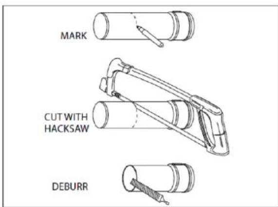
- Check with appliance manufacturer for any restrictions or limits on vent length, number of elbows, etc.
- The slope of the vent pipe must be at least 3^ (50mm per meter) back to the appliance.
- Every horizontal section must be supported.
- The venting system shall be securely supported using suitable hangers. Duravent hardware is recommended; field supplied support hardware suitable to the AHJ is acceptable, hardware must not deform on damage the vent. Make sure the load on the vent system is not supported by the appliance. On
Duravent and other certain clamp styles, 1/4" or greater All-thread may be used as an extension.
- Vertical installations must be supported every 3 meters or less.
- Elbows and tees are sufficiently supported when a bracket is fixed at the female end of the connected straight section.
Vertical Concentric
- Locate penetration.
- Cut hole in roof.
- Cut hole in ceiling above appliance.
Cut hole(s) big enough for pipe in all ceilings above appliance if installing in a multi storey installation.
- Firestop each ceiling penetration.
- Attach flashing to roof.
Slide storm collar onto flashing if using the adjustable roof flashing.
- Slide vertical termination into flashing from above until seated on flashing.
- Plumb termination and mount support bracket to structure.
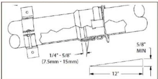


SET UP WITH IN LINE OR APPLIANCE MOUNTED FAN

INTAKE PIPE CONNECTION TO APPLIANCE

natural_image
Close-up of a hand holding a transparent cylindrical object with concentric grooves (no text or symbols visible)Flexi flue is provided for air intake. A maximum of 2 x 7m lengths can be used.
Cut tube to length where required.
Ensure ends are burr free and round, test fit flue will slide over connection.

natural_image
Close-up of a black cylindrical container with a white adhesive tape applied, no visible text or symbolsRecommended Silicon - Non-acetic, neutral cure 150°C or higher temperature rated.
Bostik RTV 926 or similar.
Apply an 8mm thick silicon bead fully around heater connection approx. 10mm from the top.
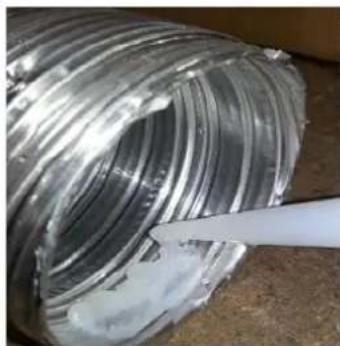
natural_image
Close-up of a transparent cylindrical pipe with white insulation, being smoothed by a tool (no text or symbols visible)Apply an 8mm silicon bead fully around the inside of the flue end (heater connection end)
Fit flue clamp over flue (loosely).

natural_image
Close-up of a mechanical assembly with coiled transparent tubing and a metallic fitting (no visible text or symbols)Slide flue onto connection spigot fully.
Tighten clamp fully.
Wipe excess silicon, visually check connection to ensure connection is fully sealed
Intake pipe joiner connection
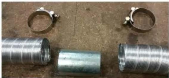
natural_image
Close-up of metallic pipe fittings and circular components on a metal surface (no text or symbols visible)
natural_image
Hand holding a transparent plastic cylindrical object with concentric grooves (no text or symbols visible)Ensure ends are burr free and round, test fit flue will slide over connection joiner.

natural_image
Three coiled metal pipes with insulation, one open showing internal structure (no text or symbols visible)Apply an 8mm thick silicon bead fully around both ends of connector approx. 10mm from the ends.

natural_image
Close-up of a transparent cylindrical pipe with white insulation, being cut with a white tool (no text or symbols visible)Apply an 8mm silicon bead fully around the inside of the flue end
Fit flue clamp over flue (loosely).
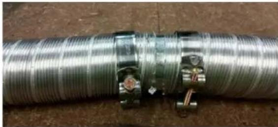
natural_image
Close-up of a coiled metal pipe with attached electrical connectors (no visible text or symbols)Slide each flue halfway onto connection joiner.
Tighten clamp fully.
Wipe excess silicon, visually check connection to ensure connection is fully sealed.
Intake connection to rooftop terminal

natural_image
Close-up of a metallic cylindrical mechanical component with no visible text or symbolsRooftop termination should be mounted and adequately supported.
Ensure clearances to combustibles are maintained.
Termination must be installed to AS5601 gas installation codes.

natural_image
Close-up of a mechanical device with metallic and white components, no visible text or symbolsApply soapy water to the fitting and to the connection on the rooftop termination
Exhaust outlet connection on heater
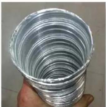
natural_image
Close-up of a hand holding a transparent plastic cylindrical container with concentric rings (no text or symbols visible)Note: The full 5m of flexi flue must be used.
Fully extend the 5m aluminum flexi flue.
NOTE- FULL LENGTH MUST BE USED.
Ensure ends are burr free and round, test fit flue will slide over connection.

natural_image
Close-up of a black cylindrical object with a white adhesive tape applied, no visible text or symbolsApply an 8mm thick silicon bead fully around heater connection approx. 10mm from the top.

natural_image
Close-up of a transparent cylindrical pipe with white insulation, being smoothed by a white tool (no text or symbols visible)Apply an 8mm silicon bead fully around the inside of the flue end (heater connection end)
Fit flue clamp over flue (loosely).

natural_image
Close-up of a metallic coiled spring component with a brass fitting (no visible text or symbols)Slide flue onto connection spigot fully.
Tighten clamp fully.
Wipe excess silicon, visually check connection to ensure connection is fully sealed
Aluminum to Poly Pro flue connection

natural_image
3D rendering of a mechanical pipe fitting with three black connectors (no text or symbols visible)Note: A total of 5m of aluminum flexi flue must be used prior to the joiner. Failure to do this will result in appliance shutdown.


natural_image
Close-up of a metallic cylindrical object with reflective surface, no visible text or symbolsApply sealant to flue inner and connector.

natural_image
Close-up of a transparent cylindrical pipe with white insulation, being cut with a white tool (no text or symbols visible)Apply sealant to flue inner and connector.
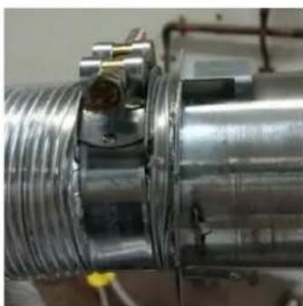
natural_image
Close-up of a metallic mechanical component with threaded end and flange (no visible text or symbols)Fit flue clamp over flue (loosely).
Slide flue onto connection spigot fully.
Tighten clamp fully.
Wipe excess silicon, visually check connection to ensure connection is fully sealed.
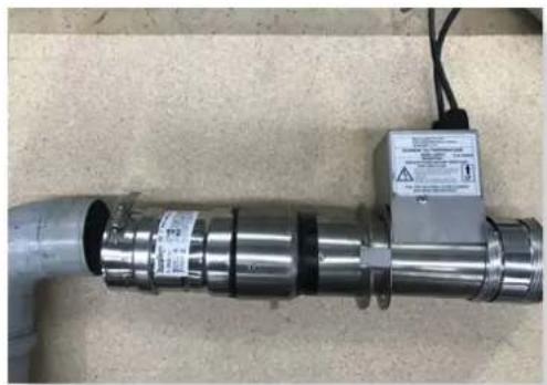
natural_image
Close-up of a metallic cylindrical mechanical component with attached electrical outlet (no visible text or symbols)
natural_image
Close-up of a metallic cylindrical industrial pipe with attached electrical control unit (no visible text or symbols)Apply soapy water to o-ring in Poly Pro flue and dampen surface of connector.
Push connector fully into Poly pro end connection.
Push both clips over to lock into place.
Where remove the catch tab from side of condensate fitting. (Twist off)
Connect condensate drain trap to adapter. Insert fully. Tighten locking hose clamp.
Condensate drain - P trap fitting

natural_image
Close-up of white PVC pipe fittings and tubing against a blue textured background (no text or symbols visible)NOTE - DRAINAGE MUST FALL TOWARDS CONDENSATE TRAP LOCATED AT THE END OF THE ALUMINUM FLUE SECTION
A P-TRAP MUST BE INSTALLED AS SHOWN
Connect 90deg elbow to Aluminum adapter facing downwards
Connect 2nd 90deg Elbow to first.
Connect vertical condensate tee to elbow with drain at bottom.
Connect drain cap to bottom of condensate tee.
Connect flue as required to rooftop termination.
P trap must be lowest part of the Polyflue system.
All poly flue must drain back to the P trap.
Connect waste pipe to p trap (PVC pressure pipe glue will be required for the connection.)
Poly Pro to Poly Pro flue connection
Verify gasket is sitting correctly.
Apply a light soapy water film to the gasket and tube end. Insert pipe fully into end fitting, Pipe will push in smoothly and evenly, should this not occur remove pipe and reset gasket. Reapply light soapy film to ensure easy fit.
Rotate clip so catch is opposite the location tab
Clip catch into place to prevent flue pipes from separating.
Ensure pipes are clipped adequately.
Ensure a minimum of 3deg fall occurs towards the drain end.


natural_image
Close-up of a white plastic pipe fitting with a black lid, lying on a light surface (no text or symbols visible)
natural_image
Close-up of a white cylindrical mechanical component with a small attached bracket (no visible text or symbols)Installation
- Pipe lengths may be cut to length. Use an alternative clamp (PPS-PAC/PPS-LBC) for the connection if a locking tab is removed.
- Cut square (not an angle) to the end of the pipe.
- Remove burrs before assembly.
-
Check with appliance manufacturer for any restrictions or limits on vent length, number of elbows, etc.
-
The slope of the vent pipe must be at least 3^ (50mm per meter) back to the appliance.
-
Every horizontal section must be supported.

Poly Pro to Roof termination

natural_image
Close-up of a white and black cylindrical pipe with metallic fittings, mounted on a tiled floor (no visible text or symbols)Ensure termination is supported.
Join Poly flue to rooftop termination
Ensure clip is fixed to prevent flue pipes from separating.
Support flues.
WIRING - FLUE TEMPERATURE LIMITING DEVICE
The flue temperature limiting device is inbuilt into the extension wiring and the flue adapter.
The connection directly connects to the loom from the appliance. The other end directly connects to the fan module.
Connections are not interchangeable.
The temperature limiting is preset and does not require adjustment.
COMMISSIONING PROCEDURE
Once the fire is installed:
- Install media.
- Check for gas leaks.
- Connect powerflue module loom to fan control unit.
- Carry out the lighting procedure.
- Check burner pressures and adjust as per Dataplate.
- Fit access cover and trim.
- Handover instructions to owner.
- Instruct owner on how to operate the fireplace safely.
- Instruct owner how to isolate appliance in an emergency.

natural_image
Exterior view of a modern office building (no signage)MEDIA INSTALLATION
PLEASE NOTE: not all media options shown are available for sale. Refer to Glen Dimplex Australia for available options.
GENERAL INSTALLATION NOTE
Lay media in a random arrangement along the entire length of the burner. Refer specific instructions below for each media type. Media where across the burner should be laid in a criss cross pattern along the full length of the burner. Do not place media along the burner channel / blocking the burner channel. Do not over stack media at one end.
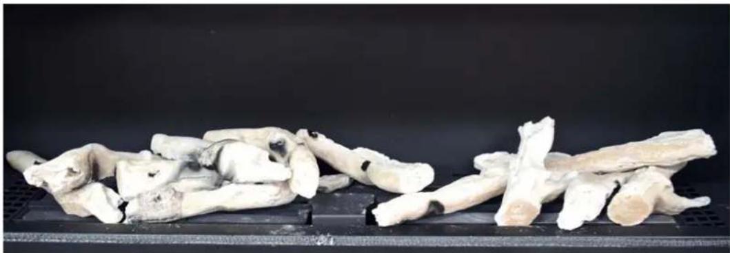
natural_image
Close-up of dried, irregularly shaped bone fragments on a dark surface against a black background (no text or symbols visible)Incorrect Media Installation
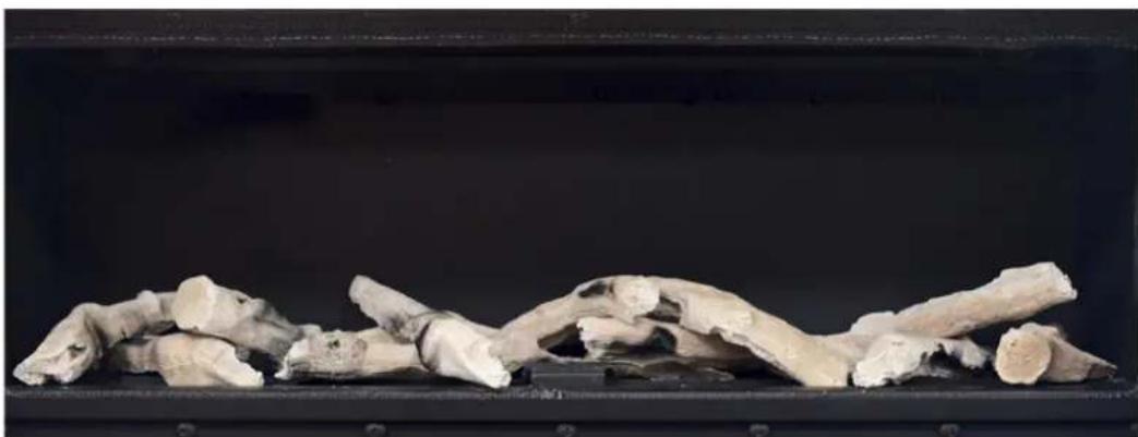
natural_image
Fossilized bone fragments displayed on a dark metal shelf against a black background (no text or symbols visible)Correct Media Installation
IMPORTANT
Do not cover or block pilot area.
Driftwood Arrangement Instruction
- Start media placement from a corner with logs over side plate.
- Lay driftwood media in a random arrangement along the entire length of the burner.
- Avoid smothering the burner channel.
- Ensure media is not heaped in areas, spread evenly along.
- Do not add extra media, or combine media types.
• Only the approved supplied media is to be used.
• Refer to Glen Dimplex for technical advice regarding media. - Do not cover pilot area.
- Do not overfill with media above the pilot cover level.
- Ensure the pilot flame is not impinged by media and can cross light the main burner.
- Do not use any other media than as supplied and recommended by the manufacturer.
- Use of other media may result in explosive media which may cause injury or damage.

natural_image
Close-up of a hot airken burner flame with glowing flames against a dark background (no text or symbols visible)TYPICAL SETUP
Media must be laid out from corner to corner of the firebox. Start media placement from a corner by placing the first log over the side cover plate.

CRITICAL ARRANGEMENTS TO AVOID
Do not place logs directly over the channel, blocking large portions of the channel.

natural_image
Close-up of a biological specimen on a black surface with a red circular icon containing a white 'X' symbol (no text or labels)Do not over stack (triple stack logs).

natural_image
Close-up of two white, textured, organic objects on a dark surface with a red circular icon containing a white 'X' symbol (no text or symbols on the objects themselves)Logs and Coal
- Lay logs first across the burner
- Lay coal media in a random arrangement along the entire length of the burner.
- Avoid smothering the burner channel. Apply coals either side of the flame channel.
- Ensure media is not heaped in areas, spread evenly along.
- Do not add extra media, or combine media types.
• Only the approved supplied media is to be used. - Do not cover pilot area.
- Do not overfill with media above the pilot cover level.
- Ensure the pilot flame is not impinged by media and can cross light the main burner.
- Do not use any other media than as supplied and recommended by the manufacturer.
- Use of other media may result in explosive media which may cause injury or damage.
- Do not use coals to raise the logs higher.
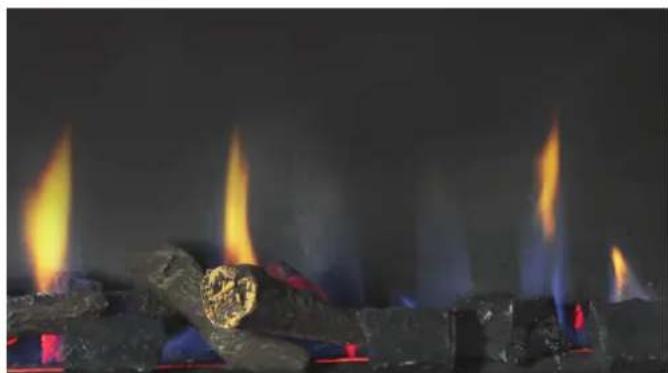
natural_image
Close-up of lit flames on a dark, flame-filled surface with visible flames and a small object (no text or symbols)TYPICAL SETUP
Arrangement Instruction
CRITICAL ARRANGEMENTS TO AVOID
Do not place logs across the channel, blocking off large portions of the channel

natural_image
Close-up of corroded metal components on a black surface, with a red circular icon containing a white 'X' symbol in the corner (no text or symbols on the main subject)Do not place coals underneath logs to raise the logs too high off the burner surface.

natural_image
Close-up of two corroded metal tools on a workbench, with a red circular icon containing a white 'X' symbol in the corner (no text or symbols on tools)Redgum with assorted coals
Spread coals randomly on and along the burner, avoid blocking the burner channel. Media may lay across the burner channel but should not be placed to smother the channel. No more than 10 coals should be placed across the burner channel.
- Lay logs first across the burner.
- Lay redgum media in a random arrangement along the entire length of the burner.
- Avoid smothering the burner channel.
- Ensure media is not heaped in areas, spread evenly along.
- Do not add extra media, or combine media types.
• Only the approved supplied media is to be used.
• Refer to Glen Dimplex for technical advice regarding media. - Do not cover pilot area.
- Do not overfill with media above the pilot cover level.
- Ensure the pilot flame is not impinged by media and can cross light the main burner.
- Do not use any other media than as supplied and recommended by the manufacturer.
- Use of other media may result in explosive media which may cause injury or damage.
• Do not use coals to raise the logs higher.

natural_image
Close-up of lit wood flakes with glowing flames and pebbles, no text or symbols visibleTYPICAL SETUP
Arrangement Instruction
Media must be laid out from corner to corner of the firebox. Start media placement from a corner by placing the first log over the side cover plate.

natural_image
Close-up of orange, irregularly shaped objects on a dark surface with a green checkmark icon in the corner (no text or symbols on objects)
natural_image
Close-up of corroded metal clamps on a dark surface, with a green checkmark icon in the corner (no text or symbols on the clamps themselves)CRITICAL ARRANGEMENTS TO AVOID
Do not place logs directly over the channel, blocking large portions of the channel.
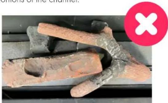
natural_image
Close-up of corroded metal components with a red circular warning symbol (no text or symbols on the objects themselves)Do not place coals underneath logs to raise the logs too high off the burner surface.

Pebbles
- Lay large pebble media in a random arrangement along the entire length of the burner.
- Avoid smothering the burner channel.
• Fill in voids with medium size pebbles.
• Fill in remaining voids with small pebbles. - Pebbles should appear as a random mix and not be stacked more than 2 high in a few spots.
- Ensure media is not heaped in areas, spread evenly along.
- Do not add extra media, or combine media types.
• Only the approved supplied media is to be used.
• Refer to Glen Dimplex for technical advice regarding media. - Do not cover pilot area.
- Do not overfill with media above the pilot cover level.
- Ensure the pilot flame is not impinged by media and can cross light the main burner.
- Do not use any other media than as supplied and recommended by the manufacturer.
- Use of other media may result in explosive media which may cause injury or damage.
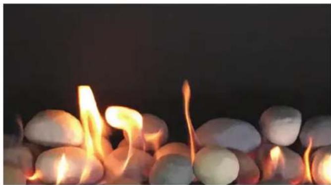
natural_image
Close-up of lit flames on smooth, rounded stones against a dark background (no text or symbols visible)TYPICAL SETUP
Coals only
- Lay coal media in a random arrangement along the entire length of the burner.
- Avoid smothering the burner channel. Apply coals either side of the flame channel.
- No more than 4 coals should cover the main flame channel.
- Ensure media is not heaped in areas, spread evenly along.
- Do not add extra media, or combine media types.
• Only the approved supplied media is to be used. - Do not cover pilot area.
- Do not overfill with media above the pilot cover level.
- Ensure the pilot flame is not impinged by media and can cross light the main burner.
- Do not use any other media than as supplied and recommended by the manufacturer.
- Use of other media may result in explosive media which may cause injury or damage.

natural_image
Close-up of bright, flame-like flames on dark wood blocks (no text or symbols visible)TYPICAL SETUP
CONVERSION DETAILS / INJECTOR - PILOT AND BURNER REMOVAL
Natural gas / Propane / ULPG
TOOLS REQUIRED
10mm spanner
15mm spanner
16mm Spanner (recommended) or small/medium shifter
No2 Phillip head screwdriver
Allen key 2.5mmAF
BURNER
Turn appliance off and allow to cool.
Turn off gas to appliance
Turn off and isolate appliance from electrical supply
Remove trim screws (2 off)
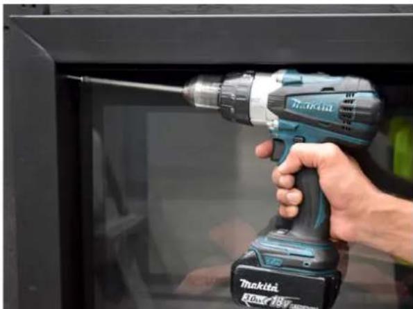
natural_image
Hand using a power drill into a black cabinet (no visible text or symbols)Remove trim (Slides out)

natural_image
Person adjusting a transparent display panel on a workbench (no visible text or symbols)Remove air deflector and air intake grate

natural_image
Close-up of a mechanical component being cut with a drill bit, showing no visible text or symbols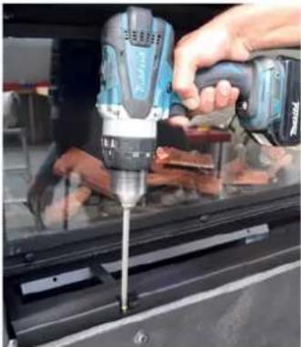
natural_image
Close-up of a hand using a power tool to lift a screwdriver into a metal frame (no visible text or symbols)Remove door screws

natural_image
Person using a Drakeira power tool to handle white fabric on a black tray (no visible text or symbols)Lift off door (Ensure door is cool before attempting)
Remove media where fitted
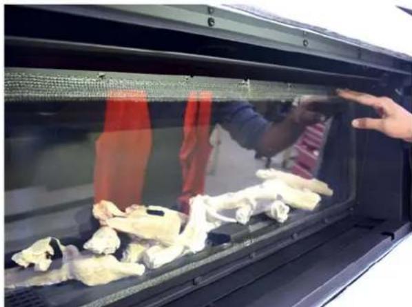
natural_image
Interior view of a modern kitchen appliance with food items on the tray and a hand adjusting it (no visible text or symbols)Remove side panels and liners to access burner locating wingnuts.

natural_image
Hand using a power tool to install components inside a vehicle (no visible text or symbols)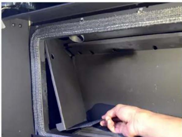
natural_image
Close-up of a hand inserting a plastic sheet into a metal frame inside a 3D printer (no text or symbols visible)Remove burner fixing screws (2 off at ends of burner)

natural_image
Close-up of a metal structural component with bolts and a textured surface (no visible text or symbols)Undo wingnuts to remove burner and lift burner from position.
Lift burner and gently support.
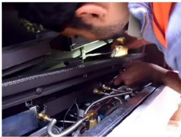
natural_image
Close-up of a technician working on a mechanical assembly with hoses and wiring (no visible text or symbols)Undo gas connection pipe at end of burner. (15mm and 16mm spanner required)

natural_image
Close-up of a mechanical component with a coiled spring and threaded fitting (no visible text or symbols)Detach the burner

natural_image
Close-up of hands holding a coiled metal cable with connectors, no visible text or symbolsLift burner out gently. Avoid marking back wall. Keep burner in the flat position until insulation is restrained (Rotating the burner may cause insulation to fall and be damaged.
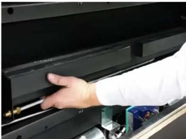
natural_image
Hand operating a mechanical device with a blue box visible (no text or symbols)
natural_image
Black rectangular electronic component with white tape, no visible text or symbolsRECOMMENDED STEP
To avoid damage to the insulation apply low tack tape to the burner to restrain the insulation into position. Avoid pressing the tape onto the media. The insulation media may easily crack if the appliance have been operated for several hours. The media may be carefully lifted out and placed flat to store until refitting. The media can be repainted using an approved high temperature paint, contact Real Flame for details.
Turn burner over gently. AVOIDING DAMAGING THE INSULATION
Loosen gas pipe nuts form injectors and move gas pipe away. Note - 15mm spanner required for the nuts, a shifter or spanner should be used to support the brass injector assembly.

natural_image
Close-up of hands connecting a mechanical component with coiled tubing and fittings (no visible text or symbols)Undo grub screw (Allen key 2.5mm AF). Injector assembly can now be removed.
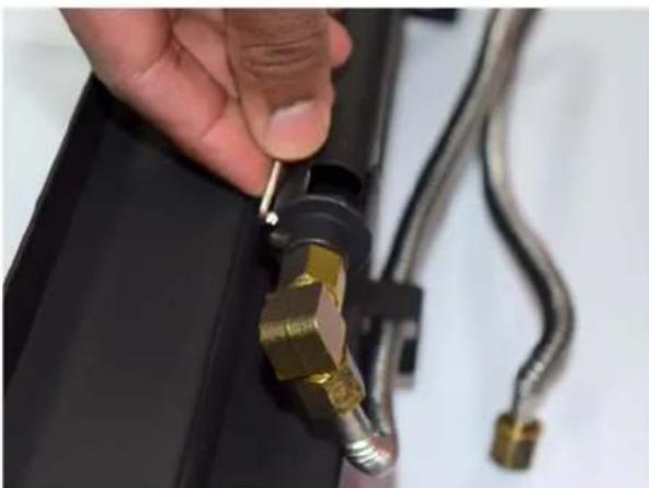
natural_image
Close-up of a hand adjusting a jet engine valve with brass fittings (no visible text or symbols)Remove all injector assemblies. Unscrew injector and replace with correct gas type.

natural_image
Close-up of a hand holding two brass fittings connected to a black mechanical component (no visible text or symbols)Loosen aeration cap screw approx. 12 turn. Rotate cap until the correct gap is achieved to suit the gas type. The listed opening is required on each side of the aeration cap. (A ruler or similar can be used to check the opening, a drill bit of the designated size can also be inserted to check the opening). Tighten screw to retain aeration cap setting.
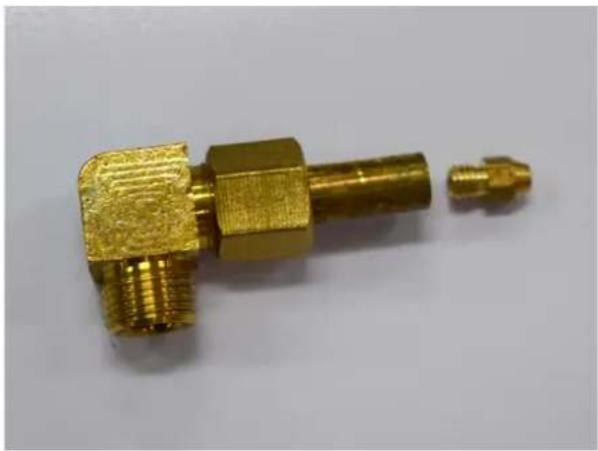
natural_image
Close-up of a brass mechanical connector with threaded end and flange, shown against a plain background (no text or symbols visible)Aeration Setting- 1200 Model
Natural Gas- 5.0 open
LPG-10.0 open
ULPG- Full open
Aeration Setting- 1800 Model
Natural Gas- 4.5 / 4.5 / 2.0mm RH end
ULPG- Full open / Full open / Full Open
LPG- 10/10/10
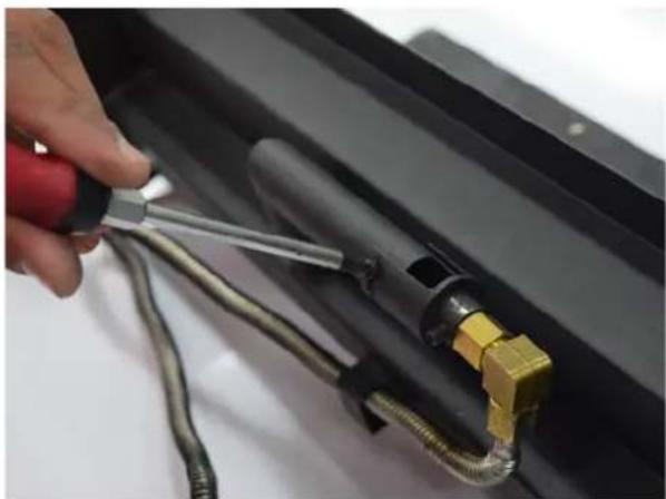
natural_image
Close-up of a hand using a power tool to adjust cable and plug into a black metal panel (no text or symbols visible)Refit injector assembly into aeration cap.
Refit gas pipe and tighten nuts.
Ensure injector assembly is sitting firmly into aeration cap and tighten grub screw.
Note - ensure injector assembly is aiming centrally into the aeration cap and tube
Correct where required.

natural_image
Close-up of a metal cutting tool measuring a metric ruler (no visible text or symbols)Rotate burner to check insulation is correctly located.
The burner consists of two types of insulation.
In the event the lower insulation (white glass wool blanket) has moved push firmly down and ensure blanket fills all gaps and corners of the burner.
Sit 12mm hard insulation back into burner. Hard insulation should sit loosely onto the top of soft insulation approximately level with the burner. Where required adjust the soft insulation to ensure sitting correctly. TAKE CARE – where the burner has been previously used the hard insulation is easily cracked.
The insulation media can be repainted using an approved high temperature paint, contact Real Flame for details.

natural_image
Close-up of a hand holding a cylindrical mechanical component with brass connectors, placed next to a ruler for scale (no visible text or symbols)
natural_image
Close-up of a metal cutting tool measuring a metric ruler (no visible text or symbols)PILOT
Remove pilot cover screen.

natural_image
Close-up of a mechanical testing setup with a tool and wiring, no visible text or symbolsGently lift pilot assembly up to enable access to pipe fittings.

natural_image
Hand holding a brown metal bracket with wires and connectors, no visible text or symbolsRemove spark lead
Remove spark probe (10mm spanner required)

natural_image
Close-up of a hand adjusting a black mechanical component on a dark surface (no visible text or symbols)Remove pilot pipe fitting from pilot assembly.

natural_image
Close-up of hands installing or adjusting a black electrical component with wires (no visible text or symbols)Remove pilot orifice from pilot or replace whole pilot assembly with correct gas type.
natural_image
Close-up of a metallic cylindrical component with engraved markings, resting on a plain surface (no text or symbols visible)PILOT RE-FITMENT
Replace pilot orifice with correct gas type.
Refit pilot gas pipe and tighten
Refit spark probe and gently tightly
Refit spark lead
Push pilot assembly down to original position and refit the bracket retaining screw.
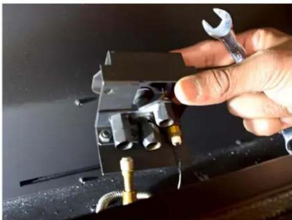
natural_image
Close-up of a hand using a wrench to adjust or install a mechanical component (no visible text or symbols)Check all wires are sitting correctly, flush to front wall. Ensure spark lead is not broken or excessively bent. Ensure lead hole is still sealed. (High temperature silicon is suitable for resealing.)
natural_image
Close-up of coiled metal tubing attached to a black industrial machine (no visible text or symbols)
natural_image
Close-up of a metallic mechanical component with bolts and a curved cover (no visible text or symbols)BURNER RE-FITMENT
Carefully place burner into firebox, supporting LH end of the burner.
Tighten gas pipe connection to the end of the burner. Burner can now be lowered fully into the firebox.
Refit burner retaining screws (2 off)
Refit End cover plates and refit holding screws.
(Screws only need to be done finger tight)
Replace media as per media fitment instructions.
Refit door. Check door seal is sitting correctly.
Hang door onto firebox. Fit screw and lift door slightly to locate.
10 x screws to be refitted
DO NOT OVER-TIGHTEN SCREWS - Hand tight is sufficient for door to seal.
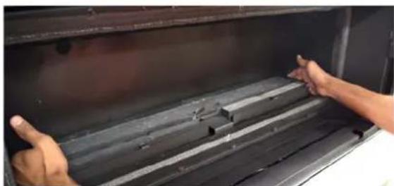
natural_image
Close-up of hands handling a black metal tray inside a large industrial container (no visible text or symbols)Fit manometer to appliance.
Start appliance and check for gas leaks in lower area and in firebox.
Adjust high and low burner pressures to the data-plate. (The appliance must operate for 3 minutes before high pressure setting can be obtained).

Check appliance for correct flame operation,
Check pilot flame, Check main burner is not smothered and flames are even along burner with correct colour and not excessively yellow or sooty. (Note it takes upto 10 minutes of operation for the flame to achieve full colour.)
Remove manometer and tighten test point. Check test point for gas leaks.
Turn appliance off.
Refit lower access panel.
Refit trim.
Refit trim retaining screws (2 off) Screws locate into 2 off pre-threaded holes in the appliance casing.
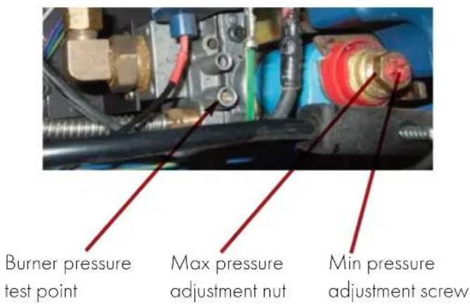
PARTS LIST
| Parts Picture | |
| Valve |  |
| SIT Pilot assembly- refer gas type |  |
| Injector Natural gas- refer gas type |  |
| Millenium receiver | 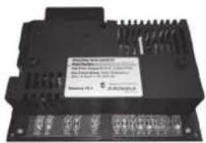 |
| Millennium remote control | 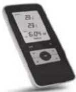 |
| Techrite Ignition System |  |
APPENDIX 1- FLUE TERMINATION

LEGEND:
T = Flue terminal
I = Mechanical air inlet
M = Gas meter
P = Electricity meter
or fuse box
Shading indicates prohibited areas for flue terminals
| Ref. | Item | Minimum clearances (mm) | |
| Natural draft | Fan assisted | ||
| a | Below eaves, balconies and other projections: | ||
| • Appliances up to 50 MJ/h input | 300 | 200 | |
| • Appliances over 50 MJ/h input | 500 | 300 | |
| b | From the ground, above a balcony or other surface † | 300 | 300 |
| c | From a return wall or external corner † | 500 | 300 |
| d | From a gas meter (M) (see 4.7.11 for vent terminal location of regulator) | 1000 | 1000 |
| e | From an electricity meter or fuse box (P) | 500 | 500 |
| f | From a drain pipe or soil pipe | 150 | 75 |
| g | Horizontally from any building structure † or obstruction facing a terminal | 500 | 500 |
| h | From any other flue terminal, cowl, or combustion air intake † | 500 | 300 |
| j | Horizontally from an openable window, door, non-mechanical air inlet, or any other opening into a building with the exception of sub-floor ventilation: | ||
| • Appliances up to 150 MJ/h input | 500 | 300 | |
| • Appliances over 150 MJ/h input up to 200 MJ/h input | 1500 | 300 | |
| • Appliances over 200 MJ/h input up to 250 MJ/h input † | 1500 | 500 | |
| • Appliances over 250 MJ/h input † | 1500 | 1500 | |
| • All fan-assisted flue appliances, in the direction of discharge | - | 1500 | |
| k | From a mechanical air inlet, including a spa blower | 1500 | 1000 |
| n | Vertically below an openable window, non-mechanical air inlet, or any other opening into a building with the exception of sub-floor ventilation: | ||
| • Space heaters up to 50 MJ/h input | 150 | 150 | |
| • Other appliances up to 50 MJ/h input | 500 | 500 | |
| • Appliances over 50 MJ/h input and up to 150 MJ/h input | 1000 | 1000 | |
| • Appliances over 150 MJ/h input | 1500 | 1500 | |
† Unless appliance is certified for closer installation
NOTES:
1 All distances are measured to the nearest part of the terminal.
2 Prohibited area below electricity meter or fuse box extends to ground level.
3 See Clause 5.13.6.6 for restrictions on a flue terminal under a covered area.
4 See Appendix J, Figures J2(a) and J3(a), for clearances required from a flue terminal to an LP Gas cylinder. A flue terminal is considered to be a source of ignition.
5 For appliances not addressed above acceptance should be obtained from the technical regulator
APPENDIX 2- WIRING DIAGRAMS
Techrite Ignition Pack

WARRANTY INFORMATION
The benefits provided to you under the following warranty are in addition to any other rights and remedies available to you under the law.
1. Warranty
If:
(a) during the first 15 years from the date of purchase (Firebox Warranty Period), there is a defect in the firebox of the Gas Burner; or
(b) during the first 2 years from the date of purchase (Parts Warranty Period), there is a defect in the gas valves or other parts of the Gas Burner, due to improper workmanship or material, Glen Dimplex will replace or repair the Gas Burner without charge. Any replacement product is warranted only for the time remaining on the original Firebox Warranty Period or the Parts Warranty Period as relevant.
2. Registration
You must register to receive the benefit of this warranty by completing the warranty registration on our website (www.realflame.com.au) or completing and mailing the attached registration card within 30 days of purchase of your Gas Burner (or, if the Gas Burner is fitted to a new home, within 30 days of the date of settlement of purchase of such new home).
3. Exclusions
Glen Dimplex is not obliged to replace or repair the Gas Burner under clause 1 if:
(a) it has been improperly stored, installed, connected, used, operated or repaired, or damaged, abused, tampered with, altered (without our written approval), or not maintained in strict accordance with our installation and operating instructions; or
(b) it has been installed in an outdoor setting.
4. Limit of Liability
The warranty provided under this warranty is limited to replacement or repair of the Gas Burner only, at our option. To the extent permitted by law, Glen Dimplex excludes liability for consequential loss or any other loss or damage caused to property or persons arising from any cause whatsoever, and damage arising from normal wear and tear.
5. Claiming under the Warranty
In order to claim under this warranty you must, within the Firebox Warranty Period or the Parts Warranty Period (as relevant), contact Glen Dimplex, providing the original proof of purchase and the details below:
Supplier Name
Date Of Purchase / settlement of property if new home
Model / Serial Number ____
This warranty does not cover the cost of claiming under the warranty or transporting the Glen Dimplex Gas Burner to and from the supplier.
Our goods come with guarantees that cannot be excluded under the Australian Consumer Law. You are entitled to a replacement or refund for a major failure and for compensation for any other reasonably foreseeable loss or damage. You are also entitled to have the goods repaired or replaced if the goods fail to be of acceptable quality and the failure does not amount to a major failure.
If you would like to speak to someone about your Gas Burner or claiming under this warranty, please contact the Service Warranty Desk on 1300 554 155.
Glen Dimplex Australia Pty Ltd
ACN 69 118 275 460
Head Office: 8 Lakeview Drive, Scoresby 3179
Telephone: (03) 8706 2000 Facsimile: (03) 8706 2001
| Website: | Telephone: | |
| www.realflame.com.au | AU: 1300 554 155 | |
| www.realflame.co.nz | NZ: +64 9 274 8265 |
© Glen Dimplex.
All rights reserved. Material contained in this publication may not be reproduced in whole or in part, without prior permission in writing from Glen Dimplex.
- ELEMENT 1200 MARK 2 & 1800 MARK 2 SPACE HEATERS ALL FLUE CONFIGURATIONS
- CONTENTS
- OPERATION INSTRUCTIONS
- INSTALLATION INSTRUCTIONS
- 5-10M INSULATED FLUE CONFIGURATION
- 10-13.5M POLYPROPYLENE FLUE CONFIGURATION
- 10-13.5M ROOFTOP POLYPROPYLENE FLUE CONFIGURATION
- WELCOME
- INSTALLATION NOTICE
- WARNING
- IMPORTANT SAFETY NOTICE
- SERVICING
- CORD REPLACEMENT
- SPECIFICATIONS OF ELEMENT 1200 MK2
- SPECIFICATIONS OF ELEMENT 1800 MK2
- USER INSTRUCTIONS
- REMOTE CONTROL GUIDE
- LOCATING THE REMOTE
- Factory Set Features
- REMOTE OPERATIONS
- Setting the day of the week and time
- Setting the hour function
- Setting the minute function
- Setting the day of the week function
- Manual mode
- Automatic mode
- Programming
- To begin programming
- Setting the day of the week
- Setting the period starting time
- Setting the temperature
- Restore factory default settings
- Teaching RF thermostat ID code to control unit
- Resetting the appliance from lockdown conditions
- TECHRITE IGNITION MODELS
- Resetting the appliance from lockdown condition- SIT
- IGNITION MODELS
- WiFi DEVICE CONTROL INSTRUCTIONS
- Introduction
- WiFi Set-up
- INSTRUCTIONS FOR iOS DEVICES
- Step 1
- Step 2
- Step 3
- Step 4
- Step 5
- Step 6
- Step 7
- Step 8
- Step 9
- Step 10
- Step 11
- Setting up remote access to the fireplace
- Step 12
- Step 13
- Step 14
- Step 15
- Step 16
- Step 17
- Step 18
- Pushing the Fireplace to a different home or local network after initial setup
- ANDROID DEVICE INSTRUCTIONS
- TROUBLESHOOTING FOR YOUR FIREPLACE
- Techrite Flash code sequence-normal operation
- Other Code
- UNIT DIMENSIONS
- MINIMUM FRAMEOUT DIMENSIONS
- 50MM TRIM
- NOTE :
- 18MM TRIM
- NOTE:
- TRIM DIMENSIONS
- TRIM DIMENSIONS
- INSTALLING ELECTRONIC EQUIPMENT ABOVE YOUR FIREPLACE
- INSTALLATION CLEARANCES
- INSTALLATION CODES
- FLUE CONFIGURATIONS
- FLUE SPECIFICATIONS
- FLUE TERMINATION LOCATIONS
- EXTREMELY IMPORTANT
- EXTERNAL WALL MOUNTED FAN MODULE INSTALLATION
- 0M-5M FLUE
- INTERNAL FAN AND WALL TERMINATION INSTALLATION
- Setup with internal fan module with wall termination - appliance mounted
- Wall termination
- Connection to wall terminal
- INTERNAL FAN & ROOF TERMINATION
- Setup with internal fan module with rooftop termination - mid flue mounted
- Rooftop termination
- Connection to rooftop terminal
- ROOFTOP TERMINATION WITH EXTERNAL MOTOR
- Setup with external rooftop termination
- LOCATION
- 5M-10M FLUE
- Setup with internal fan module with wall termination - mid flue mounted
- Insulation Instructions-
- TO 10m FLUE RUN
- Condensate Disposal
- POLY PRO GENERAL INSTALLATION REQUIREMENTS
- Joint Connections
- Installation
- Vertical Concentric
- SETUP WITH EXTERNAL WALL MOUNTED FAN TERMINAL
- IMPORTANT INSTALLATION NOTES
- INTAKE PIPE CONNECTION TO APPLIANCE
- Intake pipe joiner connection
- OUTLET CONNECTION FROM HEATER
- Poly Pro to Poly Pro flue connection
- Poly Pro to wall mounted fan module connection
- Wall Mounted Fan Module Setup
- SETUP WITH APPLIANCE MOUNTED FAN OR INLINE MOUNTED FAN AND WALL TERMINAL
- Poly Pro to Wall mounted terminal
- WIRING - FLUE TEMPERATURE LIMITING DEVICE
- SET UP WITH IN LINE OR APPLIANCE MOUNTED FAN
- Intake connection to rooftop terminal
- Exhaust outlet connection on heater
- Aluminum to Poly Pro flue connection
- Condensate drain - P trap fitting
- A P-TRAP MUST BE INSTALLED AS SHOWN
- Poly Pro to Roof termination
- COMMISSIONING PROCEDURE
- Once the fire is installed:
- MEDIA INSTALLATION
- GENERAL INSTALLATION NOTE
- IMPORTANT
- Driftwood Arrangement Instruction
- CRITICAL ARRANGEMENTS TO AVOID
- Logs and Coal
- Arrangement Instruction
- Redgum with assorted coals
- Pebbles
- Coals only
- CONVERSION DETAILS / INJECTOR - PILOT AND BURNER REMOVAL
- TOOLS REQUIRED
- BURNER
- RECOMMENDED STEP
- Turn burner over gently. AVOIDING DAMAGING THE INSULATION
- Aeration Setting- 1200 Model
- Aeration Setting- 1800 Model
- PILOT
- PILOT RE-FITMENT
- BURNER RE-FITMENT
- PARTS LIST
- APPENDIX 1- FLUE TERMINATION
- APPENDIX 2- WIRING DIAGRAMS
- WARRANTY INFORMATION
- Warranty
- Registration
- Exclusions
- Limit of Liability
- Claiming under the Warranty
Brand : Real Flame
Model : Element 1200 MK2
Category : Heating