MS-100 - Intercom Axxent - Free user manual and instructions
Find the device manual for free MS-100 Axxent in PDF.

User questions about MS-100 Axxent
0 question about this device. Answer the ones you know or ask your own.
Ask a new question about this device
Download the instructions for your Intercom in PDF format for free! Find your manual MS-100 - Axxent and take your electronic device back in hand. On this page are published all the documents necessary for the use of your device. MS-100 by Axxent.
USER MANUAL MS-100 Axxent
The basics Controls on the front side
The wired axent intercom system was developed for safe communication between the members of the system operating staff. Contrary to "walkie talkies" all members communicate with each other in full duplex, meaning simultaneous speaking and listening.
The system is based on the successful party line technique, which means that all communicating participants can listen and talk with each other (like in a conference) meaning that there is no necessity to address the individuals, for example via a matrix system.
The components are connected with each other via standard 3pin XLR, like regular balanced microphone cables, which are inexpensive and reliable and available almost everywhere. Total cable distance of 100 metres and more have been tried with the system without problems. Each intercom component is equipped with a minimum of 2 intercom connectors, making the system wiring easy.
A system consists of at least 2 components, e.g. 1 main station plus a belt-pack or 2 main stations. Each station requires to be voltage powered. Power for the beltpacks comes from a master station via the microphone cable. Same with the signal lights. Alternatively the supply voltage can be provided by external power supply model PS-100. For talking and listening a professional headset is used, either with one or with 2 ear muffs.
The call signalling is either handled by large separate signal light, looped in the regular wiring or via the built in signal lights of the components. In addition a piezo buzzer is integrated and can be activated when required, or preferred over a light signal. A beltpack (BP-100V) also contains a vibration element, in case the light is overlooked.
Operating the axent intercom system is almost self-explanatory, but here some help by giving you an oversight of the controls and their purpose as well as providing info on the system interfaces -->
The model MS-200 is the standard main station of the axent intercom system. It has two separate channels so that two user groups may communicate independently. Theses two groups can communicate separately from each other, but can not be interconnected. The operator of the main station, however, is able to communicate with both groups, either separately or with both groups simultaneously. The call buttons for both groups are also separate. One main station can supply the operating voltage for the attached intercom components via a standard XLR microphone cable. One main station provides supply voltage for a maximum of 14 beltpacks.
Controls in detail
On the front side of the main station you will find a couple of controls and plugs. On the left the 4 pin XLR male plug (1) for connecting a headset. Close by on the right (2), is the volume control for the earphone of the headset.
Side-Tone controls (3): This control determines the volume of the headsets microphone. Adjust the volume according to your needs. Too high levels may lead to feedback, so it is recommended to stay below that level.
The switch (4) has three positions: microphone ON; microphone OFF and microphone PTT = Push To Talk.
The switch (5) A, A+B and B determines with which of the user groups you communicate from the master station.
BUZZER ON OFF (6) is the ON/OFF switch for the piezo acoustical alarm. While most likely not used during a theatre performance itself, it can be a helpful aid for rehearsals.
Push buttons (7) for the alarm light, separately for channels A + B.
3 pin XLR female plug (8) is intended for an external input audio signal, such as program- or music signal. Line- and microphone levels are accepted. The input level control is located on the right hand side of the plug, so is the switch to determine the channels you want to use, either A, B or both. The power switch (9) is located on the right hand side of the panel. We recommend to connect all components prior to turning on the unit. Controls and connectors on the rear side are described on the following page —>
Controls on the rear side
Left is the power cord outlet (10) and the fuse holder (11). In case the fuse should blow, please make sure you replace it with the same type e.g. 230 V, 1 Ampère, slow blow (regular commercially available glass fuse, 5 x 20 mm). Should the new fuse become defective again you most likely have to send in the unit for repair. Further right is the voltage selector (12) which in Europe should remain in the 240 V position. When switching to 120 V by accident the unit might be damaged and no warranty claim will help.
LINE OUT: This is a 3 pin XLR male line level output providing a signal for recording, loudspeaker feed etc. The channels to be recorded can be determined by the close by switch (13).
LINE IN: 3 pin XLR female line level inputs. Here again the channel selector is located right hand (14) This input is also equipped with the (somewhat hidden) level control VOL. The volume is adjusted with a mini crew driver.
CHANNEL B – These XLR connectors (male) carry the intercom connection signals. The three XLR plugs are wired in parallel, which means you do not have to care which of the connectors you use (15).
CHANNEL A – The same applies to channel A. Please make sure that you only use high quality shielded microphone cable for the interconnection of the components, thereby avoiding hum and noise.
The Beltpack BP-100
is the second important component of an intercom system: The beltpack is—as the name indicates—normally worn on the belt, using the steel clip. In case you break this rugged clip we recommend to order a new one as a replacement part. The front side of the BP-100 carries the controls, while all connectors are located on the rear side.
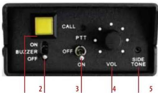
CALL-button (1), with light indicator. Below is the buzzer ON/OFF switch (2), to generate an acoustical call buzz. In the middle of the panel is the 3-position microphone switch: ON (permanently), PTT = Push To Talk and OFF (3). Finally the volume control for the earphone (4) and the SIDE-TONE-control (5) for setting the cue volume of your own microphone. For all these controls the same hints apply as outlined for the master station MS-200.
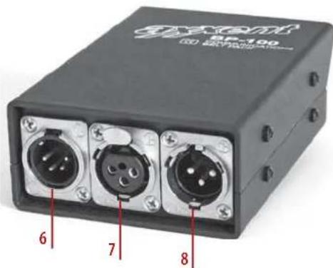
Rear side of the Beltpack BP-100
Left is the 4 pin XLR male connector (6) for your headset. Right from this is the three pin XLR input (7) for the microphone cable from the main station or from other beltpacks and the 3 pin XLR male (8) connector for looping through the intercom signals to further beltpacks, signal lights, or loudspeaker stations.
The Beltpack BP-100V
The difference between this model and the above described version BP-100 is the lack of a piezzo buzzer, providing a vibration alarm instead of it. This vibration alarm consists of a small rectangular unit with attached cable and a 3.5 mm phone jack, connecting to the BP-100V. The vibration alarm unit can be carried in your pocket and calls your attention in case the signal light is not noticed. All other controls and connectors are identical to the beltpack BP-100.
CP-100 loudspeaker station
Due to its compact size this loudspeaker station is also favourably used as a small main station. The model CP-100 may be looped in to the signal chain like any of the other intercom components. It derives its supply voltage from a main station via the microphone cable. LINE IN: This is the intercom connector for the microphone cable from the main station. LINE OUT: is for looping through the system to other intercom stations. Right hand you will notice a RJ-45 connector for supply voltage in case the loudspeaker station should not get its voltage from another main station.
As indicated before the model CP-100 may be used as loudspeaker station as well as a small main station. As a loudspeaker station the voltage is supplied by a main station such as the models MS-200 or MS-100. In case you prefer to operate the CP-100 as a small main station, an external power supply RS-1 may be connected which in addition can provide operating voltage for up to 4 beltpacks.
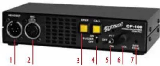
Controls on the front side
HEADSET connector (1); MIC connector (2). Instead of connecting a headset here these inputs also can be used for connecting another external microphone such as a gooseneck or handheld (dynamic). In this case the loudspeakers will be used instead of the earphone. In case you use a headset you can disengage the built-in loudspeaker with the SPKR switch (3). Right from this you will find the CALL button (4). Beneath is an ON/OFF switch for the buzzer alarm. The 3-position talk switch (5) has the options: OFF, PTT (Push To Talk) and ON. The level of the loudspeaker or the earphone of the headset is controlled by the potentiometer (6). SIDE-TONE: To control the cue volume of your own microphone (7).
The model CP-100 features a very robust 1/2 19" steel case with rubber feet for table use. In case you would like to mount the CP-100 in a 19" rack, we have available a rack mount kit RMK-100. It may also be mounted to the wall with a special wall mount kit WMK-100.
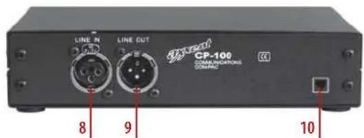
Controls on the rear side
LINE IN (8): This is the XLR intercom connector for the microphone connection cable to the main station.
LINE OUT (9): Serves as loop through to other intercom stations. On the right hand is the RJ-45 connector(10) which can be used for power supply of the unit in case it is not powered by other main stations.
As mentioned before the CP-100 can be either used as a loudspeaker station or as a small main station. As loudspeaker station the power supply is derived from a main station such as the models MS-200 or MS-100. If your prefer the CP-100 as a small main station you may also connect the external power supply RS-1 which also can provide the operating voltage for up to 4 beltpacks.
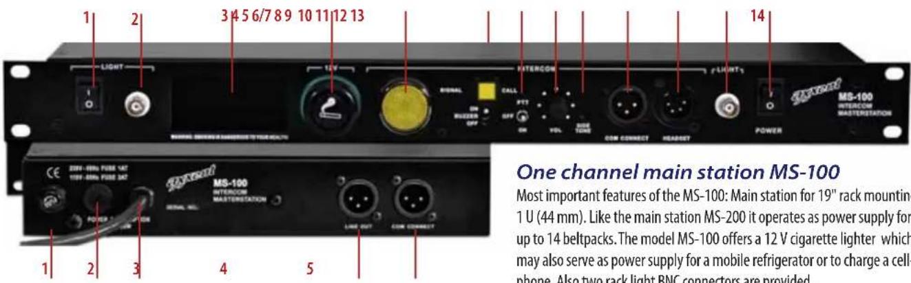
Controls on the front side
ON/OFF switch for both rack lights (1). BNC connector as input for rack light (2). Space for accessories, such as a mobile phone (3), 12 V cigarette lighter (4), SIGNAL light as call indicator (5), CALL button with light (6/7). Below this button is the ON/OFF switch for the BUZZER tone (6/7), switch for microphone: PTT=push to talk, OFF and ON (8), VOLUME control for the earphone of the headset (9) SIDE TONE volume control to set the cueing level of your own microphone (10). COM CONNECT is a 3 pin XLR male plug for intercom connection. This for example connect to a beltpack or to another signal light (11) (via a mic cable). HEADSET connector: 4 pin XLR male (12). RACKLIGHT BNC connector (13). POWER ON/OFF switch (14). Attention: switch the unit on after you made all the connections to the intercom components.
One channel main station MS-100
Most important features of the MS-100: Main station for 19" rack mounting 1 U (44 mm). Like the main station MS-200 it operates as power supply for up to 14 beltpacks. The model MS-100 offers a 12 V cigarette lighter which may also serve as power supply for a mobile refrigerator or to charge a cell-phone. Also two rack light BNC connectors are provided.
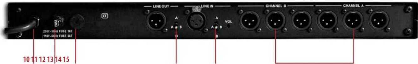
Controls on the rear side
Fuse holder (1). Standard glass fuses 5 x 20 mm, 1 A, slow blow, are used. Replace only with fuse of the same type. In case the fuse blows again the unit has to be sent in for repair. Voltage connector 120/240 V (2): in Europe this selector must be in the 240 V position. Switching to a 120V position may damage the unit (no warranty). Power cord outlet (3), LINE-OUT (4) = 3 pin XLR male connector line level for recording or as a feed for PA systems. COM CONNECT (5) this 3 pin XLR male connector is the intercom output for connection of several intercom components using standard microphone cables.
Power supply PS-100
Normally beltpacks, loudspeaker stations or signal lights receive their operating voltage from an intercom main station. These main stations are normally intended to be rack mounted. During the past few years a trend to the use of digital audio mixing consoles could be observed, eliminating in many cases the so called „side racks" since these mixing consoles also have dynamic processors on board. Sound engineers therefore avoid additional 19" equipment. We have reacted to this trend and developed an external power supply for small intercom components such as beltpacks. The voltage supply is delivered by a standard microphone cable. With the new power supply PS-100 up to 6 beltpacks may be connected.
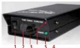
Controls on the front side
Power switch (1) – Please switch on only after connecting all other components. Voltage selector 120/240 V (2). In Europe leave this selector in the 240 V
position otherwise the unit can be damaged. Fuse holder with glass fuses, 5 x 20 mm, 200 mA slow blow (3). Only replace with fuses of the same current. In case the fuse blows again sent in the unit must be return for repair. OVERLOAD LED (4) indicates that possibly too many components have been connected. POWER LED 5).
Controls on the rear side
On the rear side of the power supply PS-100 you will find the power cord outlet and the two XLR intercom connectors (5+6). A total of 6 beltpacks may be powered by the PS-100 (for example 3 beltpacks per output or 6 on one output).
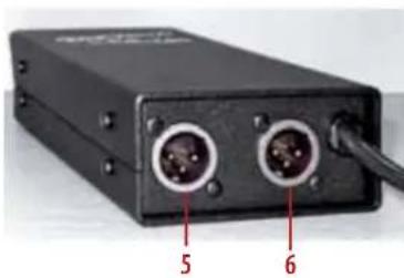
natural_image
Black electronic device with two ports and a cable, labeled with numbers 5 and 6 (no visible text or symbols beyond labels)The case of the power supply is very rugged and made of steel with a special coating for years of flawless operation. Rubber feet are provided for safe surface mounting.
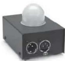
Signal light LP-100
The light dome of the LP-100 is made of white matte glass and can be noticed even at large distances. The LP-100 has no controls, solely an intercom connection in-/ and output. This means that you can position this signal light in the intercom chain wherever you want and where it is needed. The operation voltage is carried by the microphone cable.