
TS-920RC - Microphone TOA - Free user manual and instructions
Find the device manual for free TS-920RC TOA in PDF.

| Product Type | Gooseneck Microphone |
| Brand | TOA |
| Model | TS-920RC |
| Polar Pattern | Cardioid |
| Frequency Response | 100 Hz - 15 kHz |
| Impedance | 600 ohms |
| Power Requirement | Phantom power 48 V |
| Connector Type | XLR-3-31 (Male) |
| Dimensions (Head) | 9.5 mm diameter, 12 mm length |
| Total Length | Approx. 400 mm |
| Weight | Approx. 120 g |
| Material | Zinc alloy die-cast, steel mesh |
| Operating Temperature | 0°C to 40°C |
| Cleaning Instructions | Wipe with a dry cloth. Avoid water and solvents. |
| Installation | Mounts into standard 3-pin XLR floor or table plate |
| Safety | Use only with compatible phantom power source. Do not disassemble. |
| Spare Parts | Replacement gooseneck and cartridge available |
| Intended Use | Speech reinforcement in conference rooms, rostrums |
Frequently Asked Questions - TS-920RC TOA
User questions about TS-920RC TOA
0 question about this device. Answer the ones you know or ask your own.
Ask a new question about this device
Download the instructions for your Microphone in PDF format for free! Find your manual TS-920RC - TOA and take your electronic device back in hand. On this page are published all the documents necessary for the use of your device. TS-920RC by TOA.
USER MANUAL TS-920RC TOA
CONFERENCE SYSTEM TS-920 SERIES

TABLE OF CONTENTS
- SAFETY PRECAUTIONS 4
- GENERAL DESCRIPTION ...... 7
- FEATURES 7
- SYSTEM EQUIPMENT CONFIGURATION 8
- NOMENCLATURE AND FUNCTIONS 9
5.1. Central Unit TS-920RC 9
5.2. Infrared Chairman Units TS-921 and TS-821 14
5.3. Infrared Delegate Units TS-922 and TS-822 17
-
SYSTEM CONNECTION EXAMPLES ...... 20
-
INFRARED TRANSMITTER/RECEIVER INSTALLATION AND CONNECTIONS 21
7.1. Notes on Installation of the Infrared Transmitter/Receiver Unit 21
7.2. Infrared Service Areas 22
7.3. Infrared Transmitter/Receiver Arrangement Examples 24
7.4. Wiring between the Infrared Transmitter/Receiver Unit and the Central Unit .... 25
7.5. Mounting the Infrared Transmitter/Receiver Unit 27
7.6. Connections between the Infrared Transmitter/Receiver Unit and the Central Unit 29
- USING WIRED MICROPHONES AND SOUND SOURCE EQUIPMENT 33
8.1. Wired Microphone Use 33
8.2. Sound Source Equipment Use 33
- RECORDING EQUIPMENT CONNECTION 34
- CONFERENCE UNIT INSTALLATION AND SETTINGS ..... 34
- INFRARED CONFERENCE UNIT POWER SUPPLY 36
11.1.BP-900ALithium-IonBattery 36
11.2. AD-0910 AC Adapter 38
- MOUNTING THE CENTRAL UNIT ON A RACK 39
- INSTALLATION STATUS CONFIRMATION 40
- FUNCTION SETTINGS 41
14.1. Setting the Maximum Number of Open Microphones 41
14.2. Speech Priority Settings 41
14.3.Mic-Off Function 42
-
MICROPHONE MIX/CUT SWITCH SETTINGS 43
-
OPERATION 44
16.1. Initiating Speech 44
16.2. Initiating Priority Speech (TS-921 and TS-821 only) 45
16.3. Voting (TS-921 and TS-922 only) 47
16.4. Using the Recording Function 48
17. IF ACOUSTIC FEEDBACK OCCURS 54
17.1. Using the Built-in FBS Function 54
17.2. Using an External Graphic Equalizer 54
18. IF A FAILURE IS DETECTED 55
18.1. Infrared Chairman Unit TS-921/821 and Infrared Delegate Unit TS-922/822 55
18.2. Central Unit TS-920RC 57
18.3. Battery Charger BC-900 57
19. APPENDIX (INFRARED TRANSMITTER/RECEIVER CONNECTION) 58
19.1. Wiring Design 58
19.2. Design Examples ...... 60
20. SIGNAL FLOW DIAGRAM INSIDE THE CENTRAL UNIT 66
21. SPECIFICATIONS 67
21.1. Central Unit TS-920RC 67
21.2. Infrared Chairman Unit TS-921, Infrared Delegate Unit TS-922 68
21.3. Infrared Chairman Unit TS-821, Infrared Delegate Unit TS-822 69
21.4. Microphone (standard) TS-923, Microphone (long) TS-924 70
21.5. Infrared Transmitter/Receiver TS-905, TS-907 70
21.6. Lithium-Ion Battery BP-900A 71
21.7. Battery Charger BC-900 71
21.8. AC Adapter AD-0910 71
21.9. Distributor YW-1022 (2-branch distributor), YW-1024 (4-branch distributor) .... 72
21.10. Rack Mounting Bracket MB-TS920 72
1. SAFETY PRECAUTIONS
- Before installation or use, be sure to carefully read all the instructions in this section for correct and safe operation.
- Be sure to follow all the precautionary instructions in this section, which contain important warnings and/or cautions regarding safety.
• After reading, keep this manual handy for future reference.
Safety Symbol and Message Conventions
Safety symbols and messages described below are used in this manual to prevent bodily injury and property damage which could result from mishandling. Before operating your product, read this manual first and understand the safety symbols and messages so you are thoroughly aware of the potential safety hazards.

DANGER
Indicates an imminently hazardous situation, which, if not avoided, will result in death or serious injury.
When the Unit is in Use
Applicable to Lithium-ion battery
- Should the following irregularity be found during use, immediately switch off the power, take the batteries out of the unit, and keep them away from fire. Failure to do so may cause a fire or explosion.
- If you find battery leakage, discoloration, deformation or damage.
- If you detect smoke or a strange smell coming out from the batteries.
- Do not deform, modify, nor solder the batteries. Doing so may damage the battery's safety or protector mechanism, causing the batteries to fire, leak, or explode.
- Never short the positive and negative terminals with a wire or other metallic objects. Also, avoid carrying or keeping the batteries with metallic objects such as necklaces or hair pins. Doing so may cause the batteries to fire, explode, leak, or heat.
- Never heat the batteries nor throw them into a fire. Doing so may damage the battery's gas relief valve or safety mechanism, causing the batteries to fire or explode.
- Do not dip the batteries into water nor wet the battery terminals. This may corrode the batteries, possibly causing them to fire, explode, leak, or heat.
- Note correct polarity (positive and negative orientation) when inserting the batteries into a battery charger. Doing otherwise may cause them to fire, explode, leak, or heat.
- Do not use, keep, nor leave the batteries near fire or in locations where the temperature rises above 60°C such as in a sun-heated car. Doing so may damage the battery's safety or protector mechanism, causing the batteries to fire, explode, leak, or heat.
- Be sure to use the BC-900 Battery charger when recharging the batteries. Using other battery charger may cause them to fire, explode, leak, or heat.
- Use the batteries only with the equipment specified. Failure to do so may cause the batteries to fire, explode, leak, or heat.
- Do not drop the batteries nor give them a shock. Doing so may damage the battery's safety or protector mechanism, causing the batteries to fire, explode, leak, or heat.
- There is a fear of loosing one's eyesight if a battery leakage gets in one's eyes. Wash it away with clean water and consult a doctor immediately. If a battery leakage stains one's skin or clothes, wash it away with clean water as there is a fear of impairing the skin.

WARNING
Indicates a potentially hazardous situation which, if mishandled, could result in death or serious personal injury.
When Installing the Unit
Applicable to Central unit, Conference unit, Battery charger, and AC adapter
- Use the unit only with the voltage specified on the unit. Using a voltage higher than that which is specified may result in fire or electric shock.
- Do not cut, kink, otherwise damage nor modify the power supply cord. In addition, avoid using the power cord in close proximity to heaters, and never place heavy objects -- including the unit itself -- on the power cord, as doing so may result in fire or electric shock.
- Do not expose the unit to rain or an environment where it may be splashed by water or other liquids, as doing so may result in fire or electric shock.
- Avoid installing or mounting the unit in unstable locations, such as on a rickety table or a slanted surface. Doing so may result in the unit falling down and causing personal injury and/or property damage.
When the Unit is in Use
Applicable to Central unit, Conference unit, Battery charger, and AC adapter
- Should the following irregularity be found during use, immediately switch off the power, disconnect the power supply plug from the AC outlet and contact your nearest TOA dealer. Make no further attempt to operate the unit in this condition as this may cause fire or electric shock.
- If you detect smoke or a strange smell coming from the unit.
- If water or any metallic object gets into the unit
- If the unit falls, or the unit case breaks
- If the power supply cord is damaged (exposure of the core, disconnection, etc.)
- If it is malfunctioning (no tone sounds.)
- To prevent a fire or electric shock, never open nor remove the unit case as there are high voltage components inside the unit. Refer all servicing to your nearest TOA dealer.
- Do not place cups, bowls, or other containers of liquid or metallic objects on top of the unit. If they accidentally spill into the unit, this may cause a fire or electric shock.
- Do not insert nor drop metallic objects or flammable materials inside the unit, as this may result in fire or electric shock.
- Do not touch a plug during thunder and lightning, as this may result in electric shock.
Applicable to Battery charger and Lithium-ion battery
- Stop charging if the batteries are not fully charged within 5 hours.
Continuously charging over 5 hours may cause the batteries to fire, explode, leak, or heat.
Applicable to Central unit and Conference unit

- To prevent possible hearing damage, do not listen at high volume levels for long periods.

CAUTION
Indicates a potentially hazardous situation which, if mishandled, could result in moderate or minor personal injury, and/or property damage.
When Installing the Unit
• These servicing instructions are for use by qualified personnel only.
To reduce the risk of electric shock, do not perform any servicing other than that contained in the operating instructions unless you are qualified to do so. Refer all servicing to qualified service personnel.
Applicable to Central unit
- Be sure to follow the instructions below when rack-mounting the unit. Failure to do so may cause a fire or personal injury.
- Install the equipment rack on a stable, hard floor. Fix it with anchor bolts or take other arrangements to prevent it from falling down.
- When connecting the unit's power cord to an AC outlet, use the AC outlet with current capacity allowable to the unit.
- The rack-mounting screws supplied with the rack mounting bracket can be used for the TOA equipment rack only. Do not use them for other racks.
Applicable to Central unit, Conference unit, Battery charger, and AC adapter
- Never plug in nor remove the power supply plug with wet hands, as doing so may cause electric shock.
- When unplugging the power supply cord, be sure to grasp the power supply plug; never pull on the cord itself. Operating the unit with a damaged power supply cord may cause a fire or electric shock.
- When moving the unit, be sure to remove its power supply cord from the wall outlet. Moving the unit with the power cord connected to the outlet may cause damage to the power cord, resulting in fire or electric shock. When removing the power cord, be sure to hold its plug to pull.
- Avoid installing the unit in humid or dusty locations, in locations exposed to the direct sunlight, near the heaters, or in locations generating sooty smoke or steam as doing otherwise may result in fire or electric shock.
When the Unit is in Use
Applicable to Central unit, Conference unit, Battery charger, and AC adapter
- Do not place heavy objects on the unit as this may cause it to fall or break which may result in personal injury and/or property damage. In addition, the object itself may fall off and cause injury and/or damage.
- If dust accumulates on the power supply plug or in the wall AC outlet, a fire may result. Clean it periodically. In addition, insert the plug in the wall outlet securely.
- Switch off the power, and unplug the power supply plug from the AC outlet for safety purposes when cleaning or leaving the unit unused for 10 days or more. Doing otherwise may cause a fire or electric shock.
Applicable to Central unit, Conference unit, and Battery charger
- Use the dedicated AC adapter for the unit. Note that the use of other adapter may cause a fire.
Applicable to Central unit and Conference unit
- Make sure that the volume control is set to minimum position before power is switched on. Loud noise produced at high volume when power is switched on can impair hearing.
Applicable to Conference unit
- When the unit is not in use for 10 days or more, be sure to take the battery out of the unit because battery leakage may cause a fire, personal injury, or contamination of environment.
Applicable to Battery charger
- Remove the power supply plug of charger from the AC outlet after charging completion, as doing otherwise may cause a fire.
Applicable to Lithium-ion battery
- When you discard batteries, please contact the local dealer from whom you bought.
Applicable to Central unit, Conference unit, and Battery charger
This is a class A product.
In a domestic environment this product may cause radio interference in which case the user may be required to take adequate measures.
CAUTION: Risk of explosion if the battery is replaced by an incorrect type.
This conference system is not suitable for use in locations where children are likely to be present.
2. GENERAL DESCRIPTION
The TOA TS-920 Series conference system employs its infrared wireless system unit.
The Infrared chairman and Delegate units (collectively referred to as "Conference units") provide wireless communication via the Infrared transmitter/receiver unit connected to the Central unit. Since wiring to the individual Conference units is not required, they can be easily installed in freely versatile configurations.
A total of up to 192 Infrared conference units can be connected to the Central unit of each system.
The Infrared transmitter/receiver unit is required for connection of the Infrared conference units. (Refer to p. 21.)
The Central unit is used to perform system function settings, status display, etc.
3. FEATURES
- The number of Conference units to be used can be freely selected depending on the number of participants. A total of up to 192 Conference units can be installed in a single system.
- Open Microphones Number Setting function supports well-organized meeting, avoiding the confusion that can result from too many speakers trying to talk simultaneously.
- A Speech Priority Selector function permits selection of operating priority (first-in-first-out or last-in-first-out) when the Speech key is pressed.
- If any microphones are not manually turned off after speaking, the system's Mic-Off function automatically switches them off if not in use for approximately 30 seconds.
- A built-in Feedback Suppression Function (FBS) ensures more efficient reduction of acoustic feedback*. When Conference units are in use, their monitor speakers are automatically turned off, eliminating concerns about acoustic feedback.
- Depending on installation requirements, wired microphones, music playing equipment and other devices can be freely combined and used within the system.
- The Central unit has a recording function that allows it to save recorded files to either a portable USB memory device or its own internal memory. An external recording device can also be connected, making it ideal for recording the minutes of a conference.
* Acoustic feedback: The squeal or howl of a sound loop created when speaker output is picked up by a microphone, amplified by an amplifier and further output from the speaker again.
[Conference unit]
• Equipped with Voting and base/translation language selection functions. (TS-921 and TS-922 only)
- Features a selection of both Chairman and Delegate units.
- Chairman units feature a Priority Speech Key Operation function that allows the Chairman unit to take speech priority over the Delegate units with the simple press of a button.
- Conference unit microphones are attached via XLR connectors that permit easy detachment for more space-saving convenience in storage.
- Two types of Conference unit microphones are made available and freely interchangeable: Standard type and Long type.
- Infrared signal communication eliminates worries about radio interference and eavesdropping, making it possible to use the system simultaneously in adjacent rooms.
- Units can be powered by either line AC or rechargeable lithium-ion batteries.
- Up to 16 TS-905 Infrared Transmitter/Receiver units, or up to 12 TS-907 units can be installed in a single system. (If both models are combined in the same system, a total of up to 12 units can be installed.)
flowchart
graph TD
    A["Central unit TS-920RC"] --> B["Distributor YW-1024 (4-branch distributor) or YW-1022 (2-branch distributor)"]
    A --> C["Infrared Transmitter/Receiver TS-905 or TS-907"]
    A --> D["Microphone (standard) TS-923 or Microphone (long) TS-924"]
    A --> E["Infrared Chairman unit TS-921/821"]
    A --> F["Infrared Delegate unit TS-922/822"]
![TOA TS-920RC - [Conference unit] - 1](/content/2026/05/1058350/images/c8f7ab5ef4933e47279c28d9195dc5faeba2146014862c57091836758727e1fb.jpg)
natural_image
Line drawing of a rectangular electronic device with an attached cable and ports (no text or symbols)AC Adapter AD-0910RC (for TS-921/922/821/822)
![TOA TS-920RC - [Conference unit] - 2](/content/2026/05/1058350/images/406957206b39d0d9ee4a2f599d4bac79852da74dd1ef2ffd5257049f28a6f3ef.jpg)
natural_image
Isometric line drawing of a battery pack with multiple compartments and a control panel (no text or symbols)![TOA TS-920RC - [Conference unit] - 3](/content/2026/05/1058350/images/b54ac6d24a564b40df7690005213d876b0687e1f0a89e9da71efb8cc115ef1ad.jpg)
Lithium-Ion Battery BP-900A (for TS-921/922/821/822)
![TOA TS-920RC - [Conference unit] - 4](/content/2026/05/1058350/images/833f533e7aaffc094797f581342db56a00b73a4b779be7c1afccd169ef1c4cfb.jpg)
natural_image
Two isometric views of a 3D rectangular metal frame with mounting holes (no text or symbols)Rack Mounting Bracket MB-TS920 (for TS-920RC)
5. NOMENCLATURE AND FUNCTIONS
5.1. Central Unit TS-920RC
![[Top] 1 2 3 4 5 ⑥ 7 8 9 10 12 15 11 13 14 16 17 18 TOA POWER MIC UNIT GH1 CH2 CH3 CH4 DATA BATTERY FUNCTION SETTING MAX MIC UNIT EXT DATA PRIORITY FIRST FIRST FIXED NEXT LATEST LATEST FIRST FIXED PRIORITY AUTO OFF ON OFF ON MAIN AUX 1 0 10 MIX CUT SUB AUX 2 0 10 MIX CUT MAIN+SUB AUX 3 0 10 MEMORY VOTING 1 2 3 START/END MIC 1 0 10 MIC 2 0 10 MAIN SUB LINE HEADPHONES 0 10 ACCESS RECORDING USB PC STATUS FULL STOP REC FORMAT INTERNAL STATUS FULL HOLD 5 SEC Don't remove memory during access. PC 20 21 Internal of rubber cap 22 24 26 27 28 29 30 31 32 33 34 35 FBS AUTO OFF EXT CENTRAL UNIT TS-920RC](/content/2026/05/1058350/images/7bc0bad61e648cb86b5f5c2e1c5aa9e447746610c5aa24aa76251a56a06fb9ae.jpg)
1. Power switch [POWER]
Setting this switch to the ON position causes the Power indicator to light.
2. Access indicator (green) [ACCESS]
Continues to remain lit while recording to the inserted USB memory device is in progress.
Note
Avoid removing the USB memory device or turning off the Power switch (1) while this indicator is lit.
3. Data signal receiving indicator [DATA]
Lights when control data is received from the Conference unit.
4. Audio signal receiving indicators
[MIC UNIT, CH1/CH2/CH3/CH4]
Light up when audio signals are received from Conference units. Audio signals are transmitted or received through 4 channels. The number of channels to be used can be set with the Number of open microphones setting switch (8). These indicators light in the same number as that of the Conference units currently being used for speech. (Which indicator will light is not specified.)
5. Battery indicator [BATTERY]
Flashes when the lithium-ion battery of the Infrared Conference unit nears complete discharge. (In this event, the Microphone in-use indicator and the Speech indicator on the corresponding unit also flash.)
Note
Be sure to immediately replace the lithium-ion battery of the corresponding unit with the fully-charged one if this indicator begins to flash.
6. External control priority indicator [EXT, PRIORITY]
Either lights or flashes when a PC or operation panel connected to the External Control terminal (41) or (43) performs priority operation. In this event, three function setting switches (8), (9), and (10) cannot be used.
7. External control communication indicator [EXT, DATA]
Remains lit during communications with a computer (PC) or operation panel connected to the External Control terminal (41) or (43).
8. Number of open microphones setting switch [MAX MIC UNIT, 1/2/3/4]
Used to set the number of Conference units that can be simultaneously operated. The indications [1], [2], [3], and [4] represent the number of simultaneously operable units.
(Refer to p. 41 "Setting the Maximum Number of Open Microphones.")
Note
This switch is factory-preset to the [1] position.
9. Speech priority selector switch [PRIORITY]
Determines the priority mode when the Talk key of the Conference unit is pressed.
(Refer to p. 41 "Speech Priority Settings.")
| FIRST First-in-first-out priority | |
| LATEST Last-in-first-out priority | |
| FIRST:FIXED NEXT: LATEST | Priority fixed for the first unit, and last-in-first-out priority for all other subsequent units. |
Note
This switch is factory-preset to the [FIRST] position.
10. Mic-off setting switch [AUTO OFF]
Automatically turns off Conference unit microphones 30 seconds after speech is completed if the user should neglect to turn off the microphone. (Refer to p. 42 "Mic-Off Function.")
Note
This switch is factory-preset to the OFF position.
11. MIC 1 input volume control [MAIN, MIC 1]
Adjusts the input level of the MIC 1 Input Terminal (40) on the rear panel. Signals input to the MIC 1 terminal are output to the base language channel ^*1 .
12. Microphone Mix/Cut switch (for the base language channel) [MAIN, MIX/CUT]
MIX: Speech input from the Conference units, and AUX 1 and MIC 1 input signals are output to the base language channel ^*1 , and recording and line outputs.
CUT: Speech input from the Conference units is not output to the base language channel ^*1 .
The AUX 1 and MIC 1 input signals are not delivered to the recording and line outputs.
Note
This switch is factory-preset to the MIX position.
13. AUX 1 input volume control [MAIN, AUX 1]
Adjusts the input signal level of the AUX 1 Input Terminal (39) located on the rear panel. Speech input to the AUX 1 terminal is output to the base language channel ^*1 .
14. Microphone Mix/Cut switch
(for the translation language channel) [SUB, MIX/CUT]
MIX: Speech input from the Conference units is output to the translation language channel ^*2 .
CUT: Speech input from the Conference units is not output to the translation language channel ^*2 .
Note
This switch is factory-preset to the MIX position.
15. AUX 2 input volume control [SUB, AUX 2]
Adjusts the input signal level of the AUX 2 Input Terminal (37) located on the rear panel. Speech input to the AUX 2 terminal is output to the translation language channel ^*2 .
16. MIC 2 input volume control [SUB, MIC 2]
Adjusts the input level of the MIC 2 Input Terminal (38) on the rear panel. Signals input to the MIC 2 terminal are output to the translation language channel ^*2 .
17. AUX 3 input volume control [MAIN+SUB, AUX 3]
Adjusts the input signal level of the AUX 3 Input Terminal (36) located on the rear panel. Speech input to the AUX 3 terminal is output to both the base language ^1 and translation language ^2 channels.
18. Headphone channel selector switch [MAIN/SUB/LINE]
Used to choose the output to be monitored by a connected headphones from the following three sources: Base language (MAIN), Translation language (SUB), and Line (LINE) channels.
Note
This switch is factory-preset to the MAIN position.
19. USB memory port [MEMORY]
Insert a USB memory device (flash-drive/thumb drive) into this port when recording to the USB memory device.
Note
No recording can be made to the internal memory while a USB memory device is inserted into this port.
20. PC connection port (USB Mini-B) [PC]
Connect a PC to this port in order to move internal memory sound source files or delete them.
Note
Recording cannot be performed while a PC is connected to this port, nor can the internal memory be formatted by the Central unit.
21. Internal memory status indicator (green/red) [INTERNAL, STATUS]
Lights green when recordings can be made to the internal memory, and flashes green while a PC is connected to the PC connection port (20).
Flashes red when any irregularity is detected in the internal memory.
22. Remaining internal memory capacity warning indicator (orange) [INTERNAL, FULL]
Flashes when the remaining time available for recording to the internal memory falls to less than one hour, and stays lit when no time remains for recording to the internal memory.
23. USB memory status indicator (green/red) [USB, STATUS]
Lights green when recordings can be made to the connected USB memory device, and flashes red when any irregularity is detected in the USB memory device.
24. Remaining USB memory capacity warning indicator (orange) [USB, FULL]
Flashes when the remaining time available for recording to the connected USB memory device falls to less than one hour, and stays lit when no time remains for recording to the USB memory device.
25. Recording stop button [STOP]
Press this button to stop recording.
26. Recording start button [REC]
Press this button to start recording.
27. Recording status indicator (red) [REC]
Lights during recording, and flashes while the internal memory is being formatted.
28. Format button [HOLD 5 SEC]
Hold down this button for 5 seconds or more to format the internal memory and delete all sound source files.
29. Format in-progress indicator (red) [FORMAT]
Flashes while the internal memory is being formatted.
30. Voting start/end button [START/END]
Holding this button down for 1 second or more places the Central unit in Vote reception mode. While in this mode, the unit can receive voting inputs from connected individual conference units. Vote reception mode can be terminated with another depression of this button for 1 second or more, causing the voting results to be displayed on the Voting results monitor (31).
(Refer to p. 47 "Voting (TS-921 and TS-922 only)."
This button is also used to confirm installation conditions for the Infrared transmitter/receiver unit, the Conference unit.
(Refer to p. 40 "INSTALLATION STATUS CONFIRMATION.")
31. Vote result monitor [VOTING]
Computes the number of votes cast by individual Conference units for categories 1 – 3 and displays the result after voting completion.
(Refer to p. 47 "Voting (TS-921 and TS-922 only)."
32. Speech volume control [MIC UNIT]
Adjusts the microphone volume of the Conference unit.
33. Headphone jack [Ω]
Connects to headphones. (Mini-jack)
34. Headphone volume control [HEADPHONES]
Adjusts the sound volume of the headphones.
35. FBS (Feedback Suppressor) switch [FBS, AUTO/OFF/EXT]
Use to set FBS operation.
AUTO: Select to suppress acoustic feedback by automatically searching for a frequency generating acoustic feedback.
( Refer to p. 54 "Using the Built-in FBS Function.")
OFF: Select when not using the FBS function.
EXT: Select when using an external graphic equalizer. (Refer to p. 54 "Using an External Graphic Equalizer.")
Note
This switch is factory-preset to the OFF position.
![[Rear] 36 37 38 39 40 41 42 43 44 45 46 47 48 49 50 AUX 3 AUX 2 MIC 2 AUX 1 MIC 1 RS-232C USB EXT CONTROL LEVEL LINE OUT MX CUT AUX 3 REC OUT IN EQUALIZER OUT CHIME DC24V=3A(MAX) SHORT INFRARED TRANSMITTER / RECEIVER 51 52 53 54 55 SIGNAL GND](/content/2026/05/1058350/images/ecf5484a138f497ead86b35ef118f9fe22467975f7f4971578a2e818593ade6d.jpg)
36. AUX 3 input terminal [AUX 3]
-20 dB*, 10 kΩ, unbalanced, phone jack.
Connect a CD player, tape recorder, or other similar equipment to this terminal. Speech input connected to this terminal is relayed to both the base and translation language channels.
37. AUX 2 input terminal [AUX 2]
-20 dB*, 10 kΩ, unbalanced, phone jack.
Connect a CD player, tape recorder, or other similar equipment to this terminal. Speech input connected to this terminal is relayed to the translation language channel.
38. MIC 2 input terminal [MIC 2]
-60 dB*, 600 Ω, unbalanced, phone jack.
Connect a wired microphone to this terminal. Speech input from the microphone connected to this terminal is relayed to the translation language channel.
39. AUX 1 input terminal [AUX 1]
-20 dB*, 10 kΩ, unbalanced, phone jack.
Connect a CD player, tape recorder, or other similar equipment to this terminal. Speech input connected to this terminal is relayed to the base language channel.
40. MIC 1 input terminal [MIC 1]
-60 dB*, 600 Ω, unbalanced, phone jack.
Connect a wired microphone to this terminal. Speech input from the microphone connected to this terminal is relayed to the base language channel.
41. External control terminal [RS-232C]
Connect this terminal to the serial port of a PC, operation panel, or other external control equipment.
42. External control terminal selection switch
Used to select either RS-232C (41) or USB (43) external control terminals.
43. External control terminal [USB]
Connects to the external control terminal of a PC, operation panel or other connected external equipment.
44. Level volume control [LINE OUT, LEVEL]
Adjusts the line output (45) volume.
45. Line output terminal [LINE OUT]
-10 dB*, 10 kΩ, unbalanced, phone jack.
Connect an amplifier, etc. for public address applications. Speech input from the Conference unit, or MIC 1, AUX 1, or AUX 3 terminals is output to this terminal. The settings of Microphone Mix/Cut switch (12) and AUX 3 Output Mix/Cut switch (46) determine whether or not such speech input is output.
46. AUX 3 output Mix/Cut switch [LINE OUT, MIX/CUT, AUX 3]
Determines whether or not speech input is relayed from AUX 3 terminal to the line output (45). Set this switch to MIX in normal use, and to CUT to enable conference participants in other rooms to avoid potential audio feedback while speaking.
47. Recording output terminal [REC OUT]
-10 dB*, 10 kΩ, unbalanced, monaural, RCA jacks. Connect an external recording unit. An amplifier can also be connected for public address applications. The same speech signal as the line output and that of AUX 3 terminal are output to this terminal.
48. Graphic equalizer input terminal [EQUALIZER, IN]
-20 dB*, 10 kΩ, unbalanced, RCA jack.
Connect this terminal to the graphic equalizer's output terminal.
49. Graphic equalizer output terminal [EQUALIZER, OUT]
-20 dB*, 10 kΩ, unbalanced, RCA jack.
Connect this terminal to the graphic equalizer's input terminal.
50. Priority chime volume control [CHIME]
Adjusts the output volume of the chime tone that sounds when the Priority speech key on the Chairman unit is pressed.
51. DC inlet
Connect the supplied AC adapter to this terminal.
52.Cableclip
Run the AC adapter cable through this clip to prevent its plug from being removed from the DC inlet.

53. Short circuit indicator [SHORT]
Lights when the Infrared transmitter/receiver unit or its connected cable is shorted.
54. Infrared transmitter/receiver I/O terminals [INFRARED TRANSMITTER/RECEIVER]
Connect the Infrared transmitter/receiver unit, or Distributor to these terminals.
By using the YW-1022 (2-branch distributor) and/or YW-1024 (4-branch distributor), the following maximum number of Infrared transmitter/receiver units can be connected: 16 units when they are all TS-905 units, 12 units when they are all TS-907 units. (Also 12 units when both models are mixed.)
55. Functional ground terminal [SIGNAL GND]
Hum noise may be generated when external equipment is connected to the unit. Connecting this terminal to the functional ground terminal of the external equipment may reduce the hum noise.
Note
This terminal is not for protective earth.
$$ ^ {*} 0 \mathrm{dB} = 1 \mathrm{V} $$
5.2. Infrared Chairman Units TS-921 and TS-821
[TS-921 Top]
[TS -821 Top]

1. Infrared emitter/detector
The device used to transmit and receive infrared communication signals is built inside this panel.
Note
Never place any object that could block infrared signal access to this part of the unit, as this would prevent the unit from transmitting or receiving its required infrared signal.
2. Monitor speaker
Speech signals from other Conference units and other audio signals from the Central unit are output from this speaker. (Refer to the table below.)
| Model | Output signal |
| TS-921 | Base language or Translation languageNote: Switchable by the Monitor selector switch (22). |
| TS-821 | Base language |
Use the right-side Monitor volume control (20) to adjust the volume. No sound is output from the speaker of the unit in use while speaking.
3. Speech indicator
Remains lit while the microphone is in use (during speech). The indicator flashes when the unit is out of the communications service area.
4. Voting keys (TS-921 only)
Use this key when starting and stopping the Vote reception mode, and when holding a vote. The voting status indicator is provided on each key.
5. Talk key
When this key is pressed, both the Microphone in-use indicator (9) and the Speech indicator (3) light, and the microphone turns on. Pressing this key again turns off both indicators and the microphone.
Note: No microphone is supplied with the TS-921/821.
6. Priority speech key
Gives speaking priority to the current speaker. When this key is used for speech, no other delegate units can be used. Also, only the current speech made with the Priority speech key is output at the Central unit's recording and line outputs.
The key has 2 different operating modes, PTT and ALT, which can be selected with the Priority speech key operation setting switch (17).
- When PTT mode is selected, the microphone only turns on while the key is pressed, during which time the Speech (3) and Microphone in-use (9) indicators remain lit.
- When ALT mode is selected, pressing the key turns on the microphone and causes the Speech (3) and Microphone in-use (9) indicators to light. Pressing the key again turns off the microphone and these indicators.
If Chime is set to sound, a chime tone sounds when the key is pressed. For the chime setting, use the Priority chime mute switch (15).
7. Power indicator [POWER]
Lights when the power is switched ON.
This indicator also flashes when the battery level is low or the unit is outside the communications service area.
8. Microphone
Use either the TS-923 (Standard) or TS-924 (Long) dedicated microphone.
9. Microphone in-use indicator
Lights when the microphone is turned on (for speech) and flashes when the battery level is low.
[Rear]

10.DCinlet
Connect the dedicated AD-0910 AC Adapter to this terminal.
11. Power switch
Press this switch to switch on the power.
To switch off the power, press this switch again.
[Bottom]
Remove the cover on the bottom side of the unit to expose its setting switches.
![Note The figure below shows the setting switch labels for both models. [TS-921 setting switch label] [TS-821 setting switch label] 15 16 14 17 18 15 15 17 18 RESTORE ON ALT NOT USED UNIT ID ON ON 100 10 1 RESET OFF PTT PRIORITY MODE VOTE CHIME MUTE PRIORITY 100 10 1 RESTORE ON NOT USED ALT NOT USED UNIT ID 14 100 10 1 RESET OFF PTT PRIORITY MODE CHIME MUTE PRIORITY](/content/2026/05/1058350/images/dbddeaa81d520b7cbda99ffea87ad7ea7b747872cd477e0e4bb2b1585d658bd7.jpg)
12. Lithium-ion battery compartment
Install only a dedicated BP-900A Lithium-Ion Battery in this compartment.
13. Release key
Press this key to remove the lithium-ion battery.
14. Priority operation setting switch
Following completion of a priority speech, this switch is used to reset the operating status of Conference units whose operations were interrupted by the depression of a Priority speech key (6).
Set the switch to RESTORE in order to resume the mode in operation prior to initiation of the priority speech, and to RESET when resumption is not desired.
Note
This switch is factory-preset to the RESET position.
15. Priority chime mute switch
Disables the chime that sounds when the Priority speech key is pressed.
Set this switch to OFF when sound output is desired, and to ON when no sound is desired.
Note
This switch is factory-preset to the OFF position.
16. Voting activation switch (TS-921 only)
Sets whether the Vote reception mode can be
started and stopped by the Chairman unit.
Set the switch to ON to enable voting, or to OFF to disable voting.
Note
This switch is factory-preset to the OFF position.
17. Priority speech key operation setting switch
Use to set the Priority speech key operation mode.
PTT: Speech only possible while the Priority speech key is being pressed.
ALT: Speech enabled when the Priority speech key is pressed, and disabled when the key is pressed again.
Note
The switch is factory-preset to PTT.
18. Unit address number setting switch
Set the unit address number (001 - 192), taking care to ensure that the same number is not duplicated in the system.
If the number [000] is assigned to a unit, the user of that unit cannot speak. However, the unit can be used for monitoring.
Set a numeral for the ones place and tens place. Set this switch to OFF to set the hundreds place to "0" and to ON to set it to "1."
Note
This number is factory-preset to [000].
19. Rating nameplate
[Right side]

20. Monitor volume control
Adjusts the output volume of the monitor speaker and right-side headphone output.
21. Headphone jack
Connect headphones to this jack (mini-jack). Connecting the headphone cuts off the output from the monitor speaker. (Refer to the table below.)
| Model | Output signal |
| TS-921 | Base language or Translation languageNote: Switchable by the Monitor selector switch (22). |
| TS-821 | Base language |
Note
A headphone jack is located on both the left and right side panels.
22. Monitor selector switch (TS-921 only)
Selects either Base language or Translation language for the source to be output to the monitor speaker and headphones.
[Left side]

23. Headphone volume control
Adjusts the output volume of the left-side headphone output.
5.3. Infrared Delegate Units TS-922 and TS-822
[TS-922 Top] [TS -822 Top]
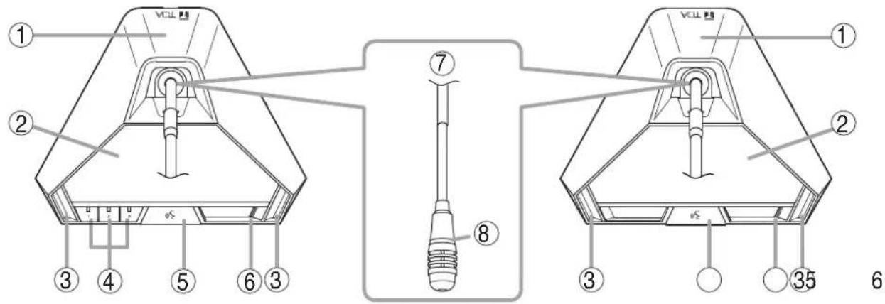
1. Infrared emitter/detector
The device used to transmit and receive infrared communication signals is built inside this panel.
Note
Never place any object that could block infrared signal access to this part of the unit, as this would prevent the unit from transmitting or receiving its required infrared signal.
2. Monitor speaker
Speech signals from other Conference units and other audio signals from the Central unit are output from this speaker. (Refer to the table below.)
| Model | Output signal |
| TS-922 | Base language or Translation languageNote: Switchable by the Monitor selector switch (17). |
| TS-822 | Base language |
Use the right-side Monitor volume control (15) to adjust the volume. No sound is output from the speaker of the unit in use while speaking.
3. Microphone in-use indicator
Lights when the microphone is turned on (for speech) and flashes when the battery level is low.
Note: No microphone is supplied with the TS-922/822.
4. Voting keys (TS-922 only)
Use these keys to start, end, and cast voting. The voting status indicator is provided on each key.
(Refer to p. 47 "Voting (TS-921 and TS-922 only)."
5. Talk key
When this key is pressed, both the Microphone in-use indicator (3) and the Speech indicator (8) light, and the microphone turns on. Pressing this key again turns off both indicators and the microphone.
6. Power indicator
Lights when the power is switched ON.
This indicator also flashes when the battery level is low or the unit is outside the communications service area.
7. Microphone
Use either the TS-923 (Standard) or TS-924 (Long) dedicated microphone.
8. Speech indicator
Remains lit while the microphone is in use (during speech). The indicator flashes when the unit is out of the communications service area.
[Rear]
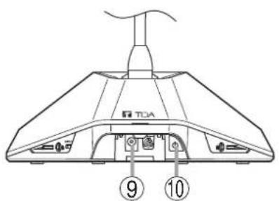
9. DC inlet
Connect the dedicated AD-0910 AC Adapter to this terminal.
10. Power switch
Press this switch to switch on the power.
To switch off the power, press this switch again.
[Bottom]
Remove the cover on the bottom side of the unit to expose its setting switches.

Cover of the setting switches
11. Lithium-ion battery compartment
Install only a dedicated BP-900A Lithium-Ion Battery in this compartment.
12. Releasekey
Press this key to remove the lithium ion battery.
13. Unit address number setting switch
Set the unit address number (001 - 192), taking care to ensure that the same number is not duplicated in the system.
If the number [000] is assigned to a unit, the user of that unit cannot speak. However, the unit can be used for monitoring.
Set a numeral for the ones place and tens place. Set this switch to OFF to set the hundreds place to "0" and to ON to set it to "1."
Note
This number is factory-preset to [000].
14. Rating nameplate
[Right side]
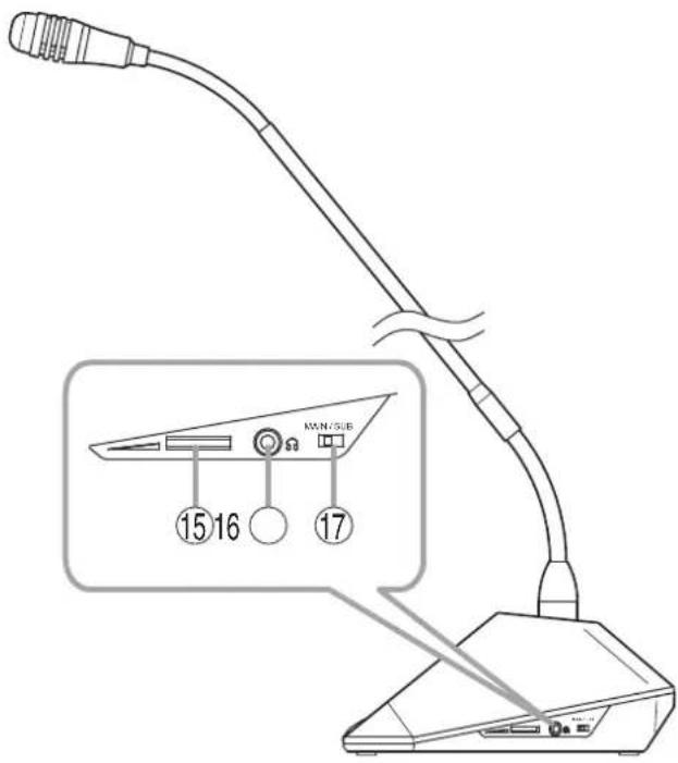
15. Monitor volume control
Adjusts the output volume of the monitor speaker and right-side headphone output.
16. Headphonejack
Connect headphones to this jack (mini-jack). Connecting the headphone cuts off the output from the monitor speaker. (Refer to the table below.)
| Model Output signal | |
| TS-922 Base language or Translation languageNote: Switchable by the Monitor selector switch (17). | |
| TS-822 Base language |
Note
A headphone jack is located on both the left and right side panels.
17. Monitor selector switch (TS-922 only)
Selects either Base language or Translation language for the source to be output to the monitor speaker and headphone.
[Left side]
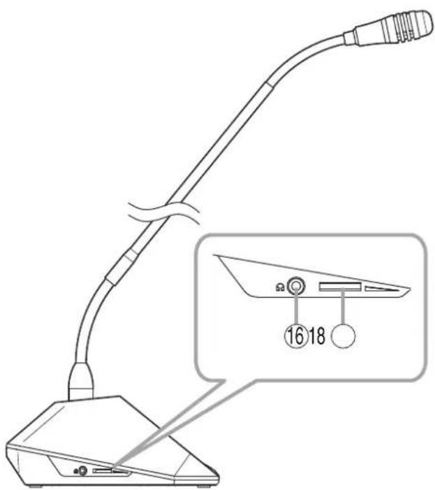
18. Headphone volume control
Adjusts the output volume of the left-side headphone output.
- SYSTEM CONNECTION EXAMPLES

flowchart
graph TD
    A["Power cord (supplied with the TS-920RC)"] --> B["AC adapter (supplied with the TS-920RC)"]
    B --> C["DC24V=3A(MAX) 0-C"]
    C --> D["AUX 3"]
    C --> E["AUX 2"]
    C --> F["MIC 2"]
    C --> G["AUX 1"]
    C --> H["MIC 1"]
    C --> I["RS-232C"]
    I --> J["SHORT"]
    J --> K["INFRARED TRANSMITTER/RECEIVER"]
    K --> L["USB EXT CONTROL"]
    L --> M["LEVEL"]
    M --> N["MIX CUT AUX 3"]
    N --> O["LINE OUT"]
    O --> P["REC OUT"]
    P --> Q["OUT EQUALIZER"]
    Q --> R["CHIME SIGNAL GND"]
    R --> S["Distributor YW-1024"]
    S --> T["Infrared transmitter/receiver TS-905/907"]
    T --> U["Infrared Chairman units TS-921 and TS-821"]
    T --> V["Infrared Delegate units TS-922 and TS-822"]
    W["Central unit TS-920RC"] --> X["PC"]
    X --> Y["External equipment connections"]
    Y --> Z["Speaker"]
    Y --> AA["Recording unit"]
    Y --> AB["GEQ Graphic equalizer"]
7. INFRARED TRANSMITTER/RECEIVER INSTALLATION AND CONNECTIONS
7.1. Notes on Installation of the Infrared Transmitter/Receiver Unit
Installing the Infrared transmitter/receiver unit in locations exposed to sunlight or in proximity to such infrared sources as fluorescent lights could result in system failures or the introduction of noise into the system. Avoid installing the Infrared transmitter/receiver unit in close proximity to infrared sources, as instructed below:
[Avoid direct sunlight]
- Cover windows with curtains or blinds to shield the unit from direct exposure to sunlight.
- Install the unit at lease 2 – 3 meters away from the nearest window.

[Keep away from fluorescent lights]
Position the unit at least 50 cm away from fluorescent lights.

[Keep away other infrared light sources]
- Lighting equipment
- LCD projectors, overhead projectors, incandescent lamps, etc.
- Mercury-arc lamps
- Plasma displays
- Remote controllers, infrared microphones, infrared equipment such as infrared LANs.
- Dimmers
7.2. Infrared Service Areas
7.2.1. Infrared transmitter/receiver
![[TS-905] Ceiling height 2.5 – 4.5 m 150° Radius of communication area](/content/2026/05/1058350/images/e86d3a1cd96320466b7463b99a5f4964d49777a1f7cea461b93ac9b180192d87.jpg)
![[TS-907] Ceiling height 5 - 7 m 90° Radius of communication area](/content/2026/05/1058350/images/38a5d507d7d15c913218ecba3f9271d3f8808167499b4762d67d65c93b2f680e.jpg)
| Model Ceiling height Radius of communication area | ||
| TS-905 | 2.5 m | Approx. 7.0 m |
| 3.0 m | ||
| 3.5 m | Approx. 6.5 m | |
| 4.0 m | ||
| 4.5 m | Approx. 6.0 m | |
| TS-907 | 5.0 m | |
| 5.5 m | ||
| 6.0 m | ||
| 6.5 m | ||
| 7.0 m | ||
Notes
- Infrared signals cannot reach the Infrared Transmitter/Receiver unit if it is hidden behind the user or other objects. Install multiple Transmitter/Receiver units in line-of-sight from all Conference units.
• Install the Infrared Transmitter/Receiver units in such a way that each Conference unit can always communicate with two or more Transmitter/Receiver units. If installed in such a way that communication is only established with one Transmitter/Receiver unit, the infrared signal may be blocked by persons or other objects, possibly causing a momentary loss of signal reception.
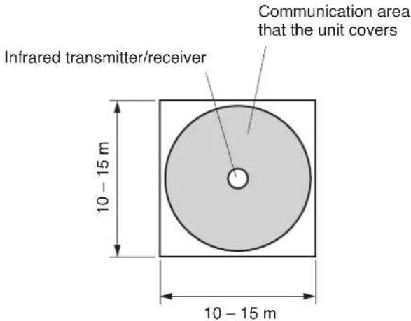
7.2.2. Infrared conference unit


The figure shows the TS-921.
7.3. Infrared Transmitter/Receiver Arrangement Examples
The area range that an Infrared transmitter/receiver unit covers differs depending on the height from the Infrared conference units to the ceiling. (Refer to p. 22.)
Arrange the Infrared transmitter/receiver units so that all Infrared conference units are included in the service area.
Note
The maximum number of Infrared transmitter/receiver units to be installed is 16 when they are all TS-905 units and 12 when they are all TS-907 units. (Also 12 when both models are mixed.)
[Conference room measuring 30 x 30 meters]
Arranging the units at intervals as illustrated permits the service area to cover every corner of the room.
Note
Determine which to use TS-905 or TS-907 depending on the ceiling height.

[Conference room using round tables]
All Infrared conference units are arranged around the table, in which case only one Infrared transmitter/receiver unit may suffice for complete coverage of conference communications.
However, it is highly recommended that two or more Transmitter/Receiver units be installed in order to avoid accidental interruptions of communications.
7.4. Wiring between the Infrared Transmitter/Receiver Unit and the Central Unit
7.4.1. Notes on wiring

flowchart
graph TD
    A["Central unit"] --> B["M0"]
    A --> C["M1"]
    B --> D["Inference 1"]
    B --> E["Inference 2"]
    C --> F["Inference 3"]
    D --> G["Inference 4"]
    E --> H["Inference 5"]
    F --> I["Inference 6"]
    G --> J["Inference 7"]
    H --> K["Inference 8"]
    I --> L["Inference 9"]
    J --> M["Inference 10"]
    K --> N["Inference 11"]
    L --> O["Inference 12"]
    M --> P["Inference 13"]
    N --> Q["Inference 14"]
    O --> R["Inference 15"]
    P --> S["Inference 16"]
    Q --> T["Inference 17"]
    R --> U["Inference 18"]
    S --> V["Inference 19"]
    T --> W["Inference 20"]
    U --> X["Inference 21"]
    V --> Y["Inference 22"]
    W --> Z["Inference 23"]
    X --> AA["Inference 24"]
    Y --> AB["Inference 25"]
    Z --> AC["Inference 26"]
When two or more Infrared transmitter/receiver units receive infrared signals from the Infrared conference units, the signal reception level increases if input signals to each Transmitter/Receiver unit are in phase. If not in phase, the signal reception level may decrease.
- To put signals in phase, ensure that the following cable length between two components are identical. Length between each Infrared transmitter/receiver unit and the Central unit L + M0 + N0 = M1 + N0 = N1 Note: This length must always be the same even if a distributor is included in the wiring.
Length between Infrared transmitter/receiver unit and distributor: L Length between distributors (where two distributors are connected): M0
Length between distributor and Central unit: N0
(In the above figure, since there is only one N0 connection, the length need not be matched for the N0 line.)
- The maximum cable length between each Infrared Transmitter/Receiver unit and the Central unit differs depending on the type of coaxial cable to be used. (Refer to p. 58.) Take care not to exceed the maximum cable length.
7.4.2. Using the distributor
- The YW-1022 is a 2-branch distributor, and the YW-1024 is a 4-branch distributor. In the case of the YW-1024, its distribution terminals may become idle depending on the Infrared Transmitter/Receiver unit's wiring. However, this presents no problem.
- Avoid connecting more than 2 distributors in series. Connecting 3 or more distributors increases high-frequency signal loss, and could result in system malfunction.
- It is possible to mix Infrared Transmitter/Receiver units not connected to any distributor, those connected to 1 distributor, and those connected to 2 distributors in the same system.
- To avoid an increase in loss, do not perform connections between distribution terminals.
Distributor block diagram

flowchart
graph LR
    A["[YW-1022"] [YW-1024]] --> B["Loss of 4.5dB"]
    B --> C["Mixing"]
    B --> D["Distributor"]
    D --> E["Distribution 1"]
    D --> F["Distribution 2"]
    E --> G["Impossible"]
    F --> G
    G --> H["Loss of 4.5dB"]
    H --> I["Mixing"]
    H --> J["Distributor"]
    J --> K["Distribution 1"]
    J --> L["Distribution 2"]
    J --> M["Distribution 3"]
    J --> N["Distribution 4"]
    K --> O["Impossible"]
    L --> P["Impossible"]
    M --> Q["Impossible"]
    N --> R["Impossible"]
    I --> S["Loss of 8.5dB"]
    S --> T["Mixing"]
    S --> U["Distributor"]
    U --> V["Distribution 1"]
    U --> W["Distribution 2"]
    U --> X["Distribution 3"]
    U --> Y["Distribution 4"]
7.4.3. Wiring examples
(Example 1)

All cables for "N" must be identical in length when the Infrared transmitter/receiver unit and the Central unit are installed in the same space.
(Example 2)
Infrared transmitter/receiver Distributor

flowchart
graph TD
    A["Left Group"] --> B["Square"]
    B --> C["Circle L"]
    B --> D["Circle L"]
    B --> E["Circle L"]
    B --> F["Circle L"]
    B --> G["Circle L"]
    B --> H["Circle L"]
    B --> I["Circle L"]
    B --> J["Circle L"]
    B --> K["Circle L"]
    B --> L["Circle L"]
    B --> M["Circle L"]
    B --> N["Circle L"]
    B --> O["Circle L"]
    B --> P["Circle L"]
    B --> Q["Circle L"]
    B --> R["Circle L"]
    B --> S["Circle L"]
    B --> T["Circle L"]
    B --> U["Circle L"]
    B --> V["Circle L"]
    B --> W["Circle L"]
    B --> X["Circle L"]
    B --> Y["Circle L"]
    B --> Z["Circle L"]
    B --> AA["Circle L"]
    B --> AB["Circle L"]
    B --> AC["Circle L"]
    B --> AD["Circle L"]
    B --> AE["Circle L"]
    B --> AF["Circle L"]
    B --> AG["Circle L"]
    B --> AH["Circle L"]
    B --> AI["Circle L"]
    B --> AJ["Circle L"]
    B --> AK["Circle L"]
    B --> AL["Circle L"]
    B --> AM["Circle L"]
    B --> AN["Circle L"]
    B --> AO["Circle L"]
    B --> AP["Circle L"]
    B --> AQ["Circle L"]
    B --> AR["Circle L"]
    B --> AS["Circle L"]
    B --> AT["Circle L"]
    B --> AU["Circle L"]
    B --> AV["Circle L"]
    B --> AW["Circle L"]
    B --> AX["Circle L"]
    B --> AY["Circle L"]
    B --> AZ["Circle L"]
    B --> BA["Circle L"]
    B --> BB["Circle L"]
    B --> BC["Circle L"]
    B --> BD["Circle L"]
    B --> BE["Circle L"]
    B --> BF["Circle L"]
    B --> BG["Circle L"]
    B --> BH["Circle L"]
    B --> BI["Circle L"]
    B --> BJ["Circle L"]
    B --> BK["Circle L"]
    B --> BL["Circle L"]
    B --> BM["Circle L"]
    B --> BN["Circle L"]
    B --> BO["Circle L"]
    B --> BP["Circle L"]
    B --> BQ["Circle L"]
    B --> BR["Circle L"]
    B --> BS["Circle L"]
    B --> BT["Circle L"]
    B --> BU["Circle L"]
    B --> BV["Circle L"]
    B --> BW["Circle L"]
    B --> BX["Circle L"]
    B --> BY["Circle L"]
    B --> BZ["Circle L"]
    B --> CA["Circle L"]
    B --> CB["Circle L"]
    B --> CC["Circle L"]
    B --> CD["Circle L"]
    B --> CE["Circle L"]
    B --> CF["Circle L"]
    B --> CG["Circle L"]
    B --> CH["Circle L"]
    B --> CI["Circle L"]
    B --> CJ["Circle L"]
    B --> CK["Circle L"]
    B --> CL["Circle L"]
    B --> CD
    style CentralUnit fill:#f9f,stroke:#333,stroke-width:2px
When installing in the same space,
- All "L" cables must be identical in length.
- All "M" cables must be identical in length.
Note
To facilitate the unification of coaxial cables used in different connections into the same length, it is highly recommended that wiring from the Central unit to the distributor mounted in a ceiling be performed with a single cable. For other ceiling wiring, using pre-cut coaxial cables of a slightly longer length will facilitate making all connections the same length.
(Example 3)

flowchart
graph TD
    A["Conference room A"] -->|L1 L1 L1| B["Distributor"]
    B --> C["M1"]
    C --> D["N Central unit"]
    E["Conference room B"] -->|L0 L0 L0 M0| F["M0"]
    F --> G["L0 L0 L0"]
    G --> H["Infrared transmitter/receiver"]
    style A fill:#f9f,stroke:#333
    style E fill:#f9f,stroke:#333
    note right of E: When installing in multiple r shut off, coaxial cables used not be matched to the same I. All L0 cables are the same I. All L1 cables are the same I. All M0 cables are the same I. L0 and L1 cables need not are used in different rooms. M0 and M1 cables need since they are used in different rooms.
Note: The above condition also applies conference systems, both in units, are apart from each other that communications cannot be used in different rooms.
When installing in multiple rooms where the light is shut off, coaxial cables used in different rooms need not be matched to the same length.
- All L0 cables are the same length.
- All L1 cables are the same length.
- All M0 cables are the same length.
- L0 and L1 cables need not be the same, since they are used in different rooms.
- M0 and M1 cables need not be the same length, since they are used in different rooms.
Note
The above condition also applies to cases in which two conference systems, both including the Conference units, are apart from each other in the same room so that communications cannot be made between the two systems.
7.5. Mounting the Infrared Transmitter/Receiver Unit
7.5.1. Ceiling mounting

Step 1. Make a 68 mm diameter hole in the ceiling.
Step 2. Attach the supplied mounting plate to the ceiling panel.
Notes
- Since the distance between two mounting screw holes is 83.5 mm, the plate can also be mounted over an electrical box.
- For open wiring, use of an electrical box is recommended.
- When attaching the plate to an electrical box, use an L-shaped BNC plug or L-shaped conversion connector.
Step 3. After wiring completion, mount the Infrared Transmitter/Receiver unit to the mounting plate. With the unit's tabs (3 places) aligned with each corresponding notch in the mounting plate, rotate the Infrared Transmitter/Receiver unit clockwise till it stops and fits into place.
7.5.2. Mounting on a microphone stand

* Not supplied with the TS-905 CE version.
Step 1. Attach the supplied stand mounting frame to the microphone stand.
Applicable thread size is U 5/16.
When the stand's thread size is NS 5/8, mount the supplied thread adapter onto the microphone stand.
Step 2. Fix the supplied mounting plate to the stand mounting frame.
Use the two supplied M3 x 6 screws for mounting.
Step 3. Attach the Infrared Transmitter/Receiver unit to the mounting plate.
Align the unit's tabs (3 places) with the corresponding notches in the plate, and then rotate the unit clockwise until it stops and fits into place.
Step 4. Mount an anti-drop screw to the mounting plate.
Note: The screw tip enters a hole in the unit and prevents its rotation.
Step 5. Perform wiring.
7.6. Connections between the Infrared Transmitter/Receiver Unit and the Central Unit
7.6.1. Connecting
Use the coaxial cable with a BNC connector to connect the Infrared transmitter/receiver unit to the Central unit.

Notes
- It is recommended that the RG-59/U, RG-6/U, or RG-11/U coaxial cable be used.
- Since the Infrared transmitter/receiver unit is equipped with the Live status indicator, it is possible to confirm whether or not the coaxial cable is correctly connected. (The indicator cannot be used for confirmation of the unit's minimum operating voltage.)
When the indicator does not light, it can be considered that the coaxial cable is not connected or shorted.
- The Central unit has a Short circuit indicator on its rear panel and the Central unit's short circuit protection circuit is common to all 4 BNC terminals. If this Short circuit indicator lights, locate the shorted point by removing each distributed cord. The indicator also lights when the number of Infrared transmitter/receiver units connected in the system exceeds the allowable limit.
7.6.2. Coaxial cable processing
| Coaxial cable Applicable BNC plug |
| RG-59/U YA-641 (1 piece per package) and CC-4901 (10 pieces per package) |
| RG-6/U YA-641 (1 piece per package) |
| RG-11/U YA-642 (1 piece per package) |
Note: Purchase both the coaxial cable and the required BNC plugs separately.
Follow the procedure below to attach the BNC connector to the coaxial cable:
Attaching a YA-641 or CC-4901 BNC Plug to the RG-59/U Cable
Step 1. Strip the jacket 10 mm from the end of the coaxial cable.
Step 2. Slip the tube supplied with the BNC plug over the jacket.
Step 3. Unravel the braided shield and turn it back, then peel away the aluminum cladding.
Step 4. Strip the dielectric 4 mm from the cable end.
Step 5. Disassemble the BNC plug as shown in the figure at right and turn the screw on the plug so that it loosens partially but remains in position.
Step 6. Insert the coaxial cable into the clamping fixture.
Step 7. Insert the clamping fixture assembly into the plug.
Step 8. Tighten the screw and then clamp the plug by tightening the clamping fixture.

Attaching a YA-641 BNC Plug to the RG-6/U Cable
Step 1. Strip the jacket 10 mm from the end of the coaxial cable.
Step 2. Unravel the braided shield and turn it back, then peel away the aluminum cladding.
Step 3. Strip the dielectric 4 mm from the cable end.
Step 4. Disassemble the BNC plug as shown in the figure at right and turn the screw on the plug so that it loosens partially but remains in position.
Step 5. Insert the coaxial cable into the clamping fixture.
Step 6. Insert the clamping fixture assembly into the plug.
Step 7. Tighten the screw and then clamp the plug by tightening the clamping fixture.

Attaching a YA-642 BNC Plug to the RG-11/U Cable
Step 1. Disassemble the BNC plug as shown in the figure at right.
Step 2. Strip the jacket 15 mm from the end of the coaxial cable.
Step 3. Insert the coaxial cable into the open ring.
Step 4. Unravel the braided shield and turn it back, then peel away the aluminum cladding.
Step 5. Strip the dielectric 5 mm from the cable end.
Step 6. Insert the coaxial cable into the clamping fixture.
Step 7. Attach the clamping ring to the plug.
Step 8. Insert the clamping fixture assembly into the plug.
Step 9. Solder the conductor to the plug.
Step 10. Clamp the plug by tightening the clamping fixture.

8. USING WIRED MICROPHONES AND SOUND SOURCE EQUIPMENT
8.1. Wired Microphone Use
Connect a wired microphone to the Central unit's MIC input and adjust its volume with the corresponding MIC input volume control.

8.2. Sound Source Equipment Use
Connect sound source equipment to the Central unit's AUX input and adjust its volume with the corresponding AUX input volume control.

9. RECORDING EQUIPMENT CONNECTION
Connect the recorder's recording input terminal to the Central unit's recording output terminal. If the recorder has its recording level control, adjust it to an appropriate recording level.
Tip: For operation of the recorder, refer to the instruction manual included with the recorder.

10. CONFERENCE UNIT INSTALLATION AND SETTINGS
Step 1. Use a screwdriver to set the Unit address number setting switch located on the unit's bottom side.
Set a numeral for the ones place and tens place.
As for the hundreds place, shift this switch to OFF for a numeral "0" and to ON for "1."
Set the unit address number (001 - 192), taking care to ensure that the same number is not duplicated in the system.
If the number [000] is assigned to a unit, the user of that unit cannot speak. However, the unit can be used for monitoring.
Note
This number is factory-preset to [000].

The figure shows the TS-921.
Step 2. Mount the microphone to the Conference unit.

Step 3. Set the Priority operation, Priority chime mute, Voting activation, and Priority speech key operation functions using the DIP switch located on the Chairman unit's bottom side.
| Setting switch | Factory-preset position |
| (1) Priority operation setting switch RESET | |
| (2) Priority chime mute setting switch OFF | |
| (3) Voting activation setting switch OFF | |
| (4) Priority speech key operation setting switch PTT | |

(4) Priority speech key operation setting switch
(3) Voting activation setting switch
(2) Priority chime mute setting switch
(1) Priority operation setting switch

(Inside the cover for TS-921) (Inside the cover for TS-821)
The figure shows the TS-921.

Step 4. Turn on the same number of microphones on the Conference units as the maximum number of open microphones set at the Central unit. Speaking into the microphone, adjust the Central unit's Speech volume control to an appropriate level.
Step 5. Initiate speech from the microphones of all Conference units, and confirm that acoustic feedback is not produced.
If feedback occurs, widen the distance between the Chairman unit and the Delegate unit or reduce the output volume to prevent feedback.
When feedback still remains, use the FBS function built in the Central unit, or an external graphic equalizer to suppress it. (Refer to p. 54 "IF ACOUSTIC FEEDBACK OCCURS.")
11. INFRARED CONFERENCE UNIT POWER SUPPLY
Use either the optional BP-900A Lithium-ion battery or the AD-0910 AC adapter for the power supply of the Infrared conference units.
11.1. BP-900A Lithium-Ion Battery
Note
Before using the BP-900A battery, be sure to carefully read the instructions on its use described in the manual enclosed with the BP-900A.
11.1.1. Inserting the lithium-ion battery

Note: A fully charged battery can be continuously used for about 10 hours.
11.1.2. Recharging
Use the BC-900 Battery charger to recharge the BP-900A Lithium-Ion battery.

Step 1. Connect the power cord to the supplied AC adapter.
Step 2. Connect the AC adapter to the Charger's power input terminal.
Step 3. Insert the AC plug into the AC wall outlet.
Step 4. Turn on the power switch.
The Power indicator lights green.
Step 5. Insert the battery fully into one of the Charger's battery receptacles with the battery oriented to the proper direction.
Ensure that the Charging status indicator lights red. If it does not light, check to see if the battery is correctly inserted.
Charging is completed within 5 hours and the Charging status indicator lights green.

WARNING
Stop charging if batteries are not fully charged within 5 hours. Continuously charging over 5 hours may cause batteries to fire, explode, leak, or heat.

CAUTION
Remove the power supply plug of charger from the AC outlet after charging completion, as doing otherwise may cause a fire.
Note
Switching the Charger's power OFF and back ON again with fully-charged (charging completed) batteries inserted will result in repeated recharge of the batteries. Battery life could deteriorate from this repetitive charging.
11.2. AD-0910 AC Adapter
Connect the AD-0910 AC adapter to the DC inlet located on the rear side panel of the Infrared conference units.

12. MOUNTING THE CENTRAL UNIT ON A RACK
Step 1. Detach both side panels of the TS-920RC Central unit. Removed screws are used in Step 2.

Step 2. Attach the MB-TS920 Rack mounting bracket to both sides of the Central unit. Use the screws removed in Step 1.
Step 3. Mount the Central unit equipped with the mounting brackets in the rack. Use the rack mounting screws and fiber washers supplied with the rack mounting bracket.


CAUTION
The rack mounting screws 5 x 12 supplied with the MB-TS920 can be used for the TOA equipment rack only. Do not use them for other racks.
13. INSTALLATION STATUS CONFIRMATION
Installation status for the Infrared transmitter/receiver unit and Conference units can be checked from the Central unit. Switch on the power to the Conference units to confirm their installation status after completing installation and connection.
Note
None of the unit's functions can be used while in installation status confirmation mode, except Priority Speech initiated from the Chairman unit.
Step 1. Switch on the power to the Central unit while holding down its Voting start/end button.
The Central unit's Battery indicator lights, placing the unit in installation confirmation mode.
(1) Each segment (1 - 3) of The Central unit's voting result display shows [0] and flashes.

DATA BATTERY Battery indicator
Lights

(2) When a connection check signal is output from the Central unit, the Microphone in-use indicator on the Conference unit that has received the signal flashes.
(3) An acknowledgement signal is transmitted from each Conference unit.
(4) A response confirmation signal is output from the Central unit that has received the acknowledgement signal, and the Microphone in-use indicator on the Conference unit that has received the signal changes from flashing to steady ON.

(5) Each segment (1 – 3) of the Voting result display provides a flashing indication of [the number of installed Chairman units], [the number of installed Delegate units], and [the total number of installed Chairman and Delegate units], respectively.

Step 2. Press the Voting start/end button for 1 second or more after confirming the indication.
The Central unit's Battery indicator and Voting result display (1 - 3) turn off. The Microphone in-use indicators on the Conference units also go out, and the installation status confirmation mode is terminated, returning the system to normal operation mode.

DATA BATTERY
□ □
Turns off

14. FUNCTION SETTINGS
14.1. Setting the Maximum Number of Open Microphones
Using the Number of open microphones setting switch on the Central unit, set the maximum number of conference units that can be simultaneously activated.
Set the switch to [1], [2], [3], or [4] depending on the type of the conference. These numbers indicate the number of units that can be simultaneously activated. (This switch is factory-preset to the [1] position.)
Note
When the Talk key is pressed at a unit exceeding the set maximum number, how the corresponding unit operates can be determined in the speech priority settings referred to in the next section.

Number of open microphones setting switch
14.2. Speech Priority Settings
Operation following the depression of the Talk key on a Conference unit, when the maximum number of speakers that can be simultaneously initiated is reached, can be selected with the Speech Priority Selector switch on the TS-920RC Central unit.
14.2.1. First-in/first-out priority
(FIRST, factory-preset switch position)
Speech is initiated on a first-come/first-served basis. When the maximum number of speakers is reached, subsequent speech requests cannot be accepted, even if the Talk key is pressed.

• Example when the number of open microphones is set to [2].
Conference unit
[First unit]

Press the talk key.

First unit: Speech possible.

[Second unit]

Press the talk key.

First unit: Speech possible.
Second unit: Speech possible.

[Third unit]

Press the talk key.

First unit: Speech possible.
Second unit: Speech possible.
Third unit: Speech not possible.
14.2.2. Last-in/first-out priority (LATEST)
When the maximum number of simultaneous speakers is reached, input from the most recent subsequent Talk key-pressed Conference unit takes precedence, thus rendering earlier speaking units inoperable.
• Example when the number of open microphones is set to [2].
Conference unit
[First unit]

Press the talk key.

First unit: Speech possible.

[Second unit]

Press the talk key.

First unit: Speech possible.
Second unit: Speech possible.
[Third unit]

Press the talk key.

First unit: Speech cancelled.
Second unit: Speech possible.
Third unit: Speech possible.
14.2.3. Priority fixed for first-enabled unit, and last-in/first-out priority for all subsequent units (FIRST: FIXED, NEXT: LATEST)
The first-enabled Conference unit is given fixed speech priority until its Talk key is pressed again. All subsequent Talk key-pressed units are given last-in/first-out priority, as in "LATEST."
• Example when the number of open microphones is set to [2].

flowchart
graph TD
    A["First unit"] --> B["Press the talk key."]
    B --> C["First unit: Speech possible."]
    C --> D["Second unit: Speech possible."]
    D --> E["First unit: Speech possible."]
    E --> F["Second unit: Speech possible."]
    F --> G["Third unit: Speech possible."]
    G --> H["First unit: Speech possible."]
    H --> I["Second unit: Speech cancelled."]
    I --> J["Third unit: Speech possible."]
    J --> K["Fourth unit: Speech possible."]
    K --> L["First unit: Speech possible."]
    L --> M["Second unit: Speech cancelled."]
    M --> N["Third unit: Speech cancelled."]
    N --> O["Fourth unit: Speech possible."]
14.3. Mic-Off Function
This function automatically turns off the microphone if the user neglects to turn it off following speech completion.
This function is enabled when the Mic-off setting switch on the TS-920RC Central unit is set to the ON position.
The microphone automatically turns off if a duration of silence lasts for about 30 seconds.
It is recommended that the Mic-off setting switch be set to the OFF position when not specifically using this function. (The Mic-off setting switch is factory-preset to the OFF position.)
Notes
- When the Mic-off setting switch is set to the ON position, the microphone automatically turns off if there is a silent interval of about 30 seconds, even though a speech may be in progress. In conferences, where long pauses during speeches can be experienced, set the switch to the OFF position.
- The Mic-Off function may not be operated correctly in high-noise areas.

15. MICROPHONE MIX/CUT SWITCH SETTINGS
Whether to output voice signals from Conference units to the base or translation language channel can be determined by setting the Microphone Mix/Cut switch on the TS-920RC Central unit. Outputs for individual inputs (MIC 1 – 2, and AUX 1 – 3) to the Central unit also change depending on the switch setting.
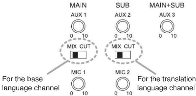
[Switch setting relationship of input to base/translation language channel]
- Speech output from Conference units depends on the switch setting. When the MAIN switch is set to the MIX position, speech is output to the base language channel. When the SUB switch is set to the MIX position, speech is output to the translation language channel.
- Inputs to the MIC 1 and AUX 1 terminals are output to the base language channel, except during priority speech from the Chairman unit, regardless of the switch setting.
- Inputs to the MIC 2 and AUX 2 terminals are output to the translation language channel, except during priority speech from the Chairman unit, regardless of the switch setting.
- Inputs to the AUX 3 terminal are always relayed to both the base and translation language channels regardless of the switch setting.
[Input/output relationship to switch settings]
| Microphone Mix/Cut switch | Input | Output | ||||
| Monitor speaker on the Conference unit Headphones* on the Central unit | Central unit | |||||
| MAIN SUB | Base language | Translation language | Line output Headphone* | Recording output | ||
| MIX MIX | Conference unit | √ | √ | √ | √ | |
| MIC 1 | √ | - | √ | √ | ||
| AUX 1 | ||||||
| MIC 2 | - | √ | - | - | ||
| AUX 2 | ||||||
| AUX 3 | √ | √ | △ | √ | ||
| MIX CUT | Conference unit | √ | - | √ | √ | |
| MIC 1 | √ | - | √ | √ | ||
| AUX 1 | ||||||
| MIC 2 | - | √ | - | - | ||
| AUX 2 | ||||||
| AUX 3 | √ | √ | △ | √ | ||
| CUT MIX | Conference unit | - | √ | √ | √ | |
| MIC 1 | √ | - | - | - | ||
| AUX 1 | ||||||
| MIC 2 | - | √ | - | - | ||
| AUX 2 | ||||||
| AUX 3 | √ | √ | △ | √ | ||
| CUT CUT | Conference unit | - | - | √ | √ | |
| MIC 1 | √ | - | - | - | ||
| AUX 1 | ||||||
| MIC 2 | - | √ | - | - | ||
| AUX 2 | ||||||
| AUX 3 | √ | √ | △ | √ | ||
√ : Indicates that individual inputs are output.
— : Indicates that individual inputs are not output.
△ : Indicates that output can be determined by the setting of the AUX 3 Output Mix/Cut switch (located on the TS-920's rear panel).
* Select output from MAIN (base language), SUB (translation language), and LINE (line output) sources using the Headphone Channel Selector switch.
16. OPERATION
16.1. Initiating Speech
Step 1. Press the Talk key on the Conference unit.
The Speech indicator and Microphone in-use indicator light, placing the unit in speech mode.
No sound is output from the monitor speaker while both indicators are continuously lit.
Note
The unit cannot be used for speech if the indicators do not light.
Step 2. Speak into the microphone.
Step 3. Press the Talk key again after speech completion.
The indicators go out, and sound can be output from the monitor speaker.
Note
When the user forgets to turn off the microphone, the Mic-Off function automatically turns off the microphone approximately 30 seconds after speech completion. (Refer to p. 42.)

The figure shows the TS-921.
16.2. Initiating Priority Speech (TS-921 and TS-821 only)
The Chairman unit features the function that allows its speech to take precedence over that of the Delegate unit. The Chairman unit's speech is prior to the AUX 1, AUX 2, AUX 3, MIC 1, and MIC 2 inputs.
The priority speech method can be determined by the Priority speech key operation setting switch built in the Chairman unit's bottom.
Chairman unit's bottom

(Inside the cover for TS-921) (Inside the cover for TS-821)
16.2.1. When the Priority speech key is set to PTT type (Factory-preset)
Step 1. Speak while holding down the Priority speech key.
Both the Speech indicator and the Microphone in-use indicator light, placing the unit in priority speech mode. No sound is output from the monitor speaker while both indicators are continuously lit. A chime tone* sounds at other units, preventing them from being used for speaking.
* The chime tone can be enabled or disabled using the Priority Chime Mute switch located on the bottom side of the unit.
ON: No chime sounds.
OFF: Chime sounds. (Factory-preset position)
Note
When two or more Chairman units are used in a system, a priority speech currently in progress from one unit can be interrupted by pressing the Priority speech key of another Chairman unit, allowing the latter unit to go through. (Last-in-first-out priority)
Step 2. Release the Priority speech key after speech completion.
Both indicators go out, and sound can be output from the monitor speaker.
Note
After the priority speech is completed, the other interrupted unit resumes operation as predetermined by the setting of the Interrupted Priority operation setting switch located on the bottom side of the unit.
RESTORE: Resumes the unit's mode prior to being interrupted by the priority speech.
RESET: Resets all units currently being used for speech (Factory-preset position).
When an interrupted party wishes to continue to speak, the Speech key must again be pressed.
Note
The Chairman unit that initiated the priority speech automatically returns to its original mode following priority speech completion, regardless of its Priority operation setting switch setting.
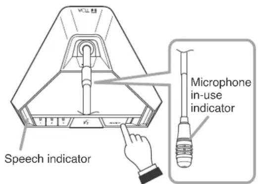
The figure shows the TS-921.
Chairman unit's bottom

The figure shows the TS-921.
(Inside the cover for TS-921)
Priority operation setting switch
Priority chime mute setting switch
(Inside the cover for TS-821)
Priority operation setting switch
Priority chime mute setting switch

16.2.2. When the Priority speech key is set to ALT type
Step 1. Press the Priority speech key.
Both the Speech indicator and the Microphone in-use indicator light, placing the unit in priority speech mode. No sound is output from the monitor speaker while both indicators are continuously lit. A chime tone* sounds at other units, preventing them from being used for speaking.
* The chime tone can be enabled or disabled using the Priority chime mute switch located on the bottom side of the unit.
ON: No chime sounds.
OFF: Chime sounds. (Factory-preset position)
Note
When two or more Chairman units are used in a system, a priority speech currently in progress from one unit can be interrupted by pressing the Priority speech key of another Chairman unit, allowing the latter unit to go through. (Last-in-first-out priority)
Step 2. Speak into the microphone.
Step 3. Press the Priority speech key again after speech completion.
Both indicators go out, and sound can be output from the monitor speaker.
Note
After the priority speech is completed, the other interrupted unit resumes operation as predetermined by the setting of the Interrupted Priority operation setting switch located on the bottom side of the unit.
RESTORE: Resumes the unit's mode prior to being interrupted by the priority speech.
RESET: Resets all units currently being used for speech (Factory-preset position).
When an interrupted party wishes to continue to speak, the Speech key must again be pressed.
Note
The Chairman unit that initiated the priority speech automatically returns to its original mode following priority speech completion, regardless of its Priority operation setting switch setting.

The figure shows the TS-921.
Chairman unit's bottom

The figure shows the TS-921.
(Inside the cover for TS-921)
Priority operation setting switch
Priority chime mute setting switch
(Inside the cover for TS-821)
Priority operation setting switch
Priority chime mute setting switch

16.3. Voting (TS-921 and TS-922 only)
Vote Reception mode can be started and stopped using either the Central unit or Chairman unit.
To perform this operation from the Chairman unit, set the Voting activation setting switch to ON as shown in the figure.

Step 1. Set the unit to Vote reception mode.
On the Central unit, hold down the Voting start/end button for 1 second or more. On the Chairman unit, simultaneously press Voting keys [1] and [2] for 1 second or more.

The Voting result display (1 – 3) on the Central unit, and the Voting status indicators on the Conference units flash, enabling voting.
(In this event, the Voting Result Display shows [--- --- 0].)
Only a priority speech can be initiated by way of the Chairman unit's Priority speech key during voting operation of each conference unit, and the currently used microphones of all other units are turned off.
Step 2. Vote.
Press the desired Voting key on the Conference unit, and the corresponding Voting status indicator lights. (Other Voting status indicators remain flashing.)
The totaled number of votes polled with the press of the voting keys is instantly displayed on the Central unit's voting result display.

Tips
• To cancel voting
Press the lit key (initially pressed for voting) again.
All keys will flash, indicating that voting is cancelled.
• To change voting
Press any flashing key (to use in voting).
The first key pressed is cancelled, and the last key pressed is enabled and continuously lit.
Step 3. Terminate voting.
Again hold down the Voting start/end button on the Central unit for 1 second or more or alternatively the Chairman unit's Talk key.
Voting operations from the Conference units are confirmed and Voting status indicators [1] through [3] go out. The result of computed votes is displayed on Voting result displays [1] through [3] on the Central unit.
(For the Chairman unit)

Note
If voting operation was activated by the Central unit, this operation cannot be terminated by the Chairman unit. However, if it was activated by the Chairman unit, it can be terminated by the Central unit as well.
Step 4. Clear the Voting result display.
Press the Voting start/end button on the Central unit for 1 second or more once again. The display contents are cleared from the Central unit's Voting result display.
16.4. Using the Recording Function
The Central unit is equipped with a recording function, making it possible to create sound source files by recording conference dialog and the like to a commercially available USB memory device. The unit is also equipped with internal memory for recording operations, and allows recording even when abnormalities arise with the USB memory device.
Note
Only recording can be performed by the Central unit. Use a PC to reproduce, delete or copy sound source files.
16.4.1. Notes on use
Important
Avoid removing the USB memory device during recording. If removed, the USB memory device might not continue to function properly, or data could be lost.
- Avoid simultaneously connecting a USB memory device and PC to the Central unit.
- The USB memory device cannot be formatted by the unit.
- While a PC is connected, neither recording nor internal memory formatting can be performed by the unit.
- Only USB memory devices can be inserted into the USB memory port. Inserting other USB devices could result in operational failure.
- Move the sound source file created in the USB memory device to a PC or other device without saving it to the USB memory device.
- When inserting or removing the USB memory device or PC connector, do not apply unreasonable force to the port. Failure to observe this instruction could lead to failure of the unit or damage to the PC or other devices.
- Ensure that the USB memory device or PC connector is removed when moving the unit from one place to another. Moving the unit with such devices inserted could cause failure to the unit or damage to the USB memory device or PC connection port.
- Be sure to replace the dustproof cover over the USB memory port and the PC connection port to prevent dust or foreign objects from entering the ports when not in use.
- Be sure to back up recorded internal memory sound source data to a PC or other device, as data could be lost due to the unit's failure or faulty operation.
16.4.2. Usable USB memory devices
- USB memory device (flash drive) with a capacity of up to 32 GB.
- Compatible with USB 2.0 devices.
- When using a USB memory device with the Central unit for the first time, format it with a PC before using.
Formatting conditions are as follows:
File system: FAT32
Allocation unit size: At least 4KB
Note
Perform full formatting, not quick formatting.
- Insert the USB memory device into the PC and perform error checking before use.
- Ensure that the USB memory device is ONLY used with the Central unit, and avoid using it for other purposes.
- The Central unit is not compatible with USB memory devices having other specialized functions, such as security functions.
- There may be cases in which a USB flash drive cannot be used with the TS-920RC, depending on the drive's attributes or recording conditions.
16.4.3. Sound source file specifications and filenames
Notes
- All sound inputs are mixed and recorded.
- Noise may be generated, depending on the contents or volume settings of the input sound source. If annoying, adjust the sound volume of the conference unit or external sound source.
Shown below are specifications and filename format for recorded sound source files:
- Specifications
Recording format: MP3 (monaural)
Sampling frequency: 32 kHz
Bit rate: 128 kbps
Maximum file size: 54.9 MB (recording time: 1 hour)
Tips
- Since the sound source file is automatically divided each time one hour elapses, the above is the maximum size.
- The size of the internal memory is 1 GB, allowing recordings to be made for a total of approximately 18 hrs.
- Filename format
A filename indicating the Year, Month, Date, Hour, Minute and Second of the time that the recording was started is automatically assigned to each file as follows:
Sound source filename: YYYYMMDD_HHMMSS.mp3
Example
In the case of a recording started at precisely 10 o'clock AM on January 1, 2019, the filename "20190101_100000.mp3" is assigned when the recording is stopped.
When a recording is continuously made for longer than one hour, the sound source file will automatically be divided whenever one hour passes, and the resulting file saved under a newly assigned filename.
[Time Setting and Confirmation]
Recording start time of a sound source filename is in accordance with the Central unit's internal clock. The internal clock can be set and confirmed using a connected PC installed with the TS-820RC/920RC Time setting tool.
The TS-820RC/TS-920RC Time setting tool can be downloaded from the TOA product data download site (https://www.toa-products.com/international/).
Click on the link above to access the download site, then enter the model number (TS-920RC) in the Model No. field to search for the specified software and download accordingly.
16.4.4. Recording to a USB memory device
A commercially available USB memory device (flash drive/thumb drive) is required to make USB memory recordings using the Central unit. Prepare a USB memory device that meets all the conditions shown in the section, "Usable USB memory devices" on p. 49.
[Procedure for recording to a USB memory device]
![TOA TS-920RC - [Procedure for recording to a USB memory device] - 1](/content/2026/05/1058350/images/a2dd872be20abb66d35bc4f7c2a05e1b0b572ec8aca82642cd183da5c5d4ae12.jpg)
flowchart
graph TD
    A["MEMORY"] -->|ACCESS Access indicator| B["RECORDING USB"]
    B --> C["STATUS FULL"]
    C --> D["STOP REC FORMAT HOLD 5 SEC"]
    style A fill:#f9f,stroke:#333
    style B fill:#ccf,stroke:#333
    style C fill:#cfc,stroke:#333
    style D fill:#fcc,stroke:#333
Step 1. Insert the USB memory device into the USB memory port.
If the inserted USB memory device is usable, the USB memory status indicator lights green.
Important
When a USB memory device is inserted, do not remove it or turn off the power switch while the Access indicator is lit. Failure to observe this instruction could cause damage to the USB memory device.
Step 2. Press the Recording Start button.
Recording begins. The Recording status indicator lights red and the Access indicator lights green.
Important
In some cases, quite a few seconds could pass after the USB memory device is inserted before the USB memory status indicator lights green. Since the Central unit is in the process of recognizing the USB memory device during this time, do not remove the USB memory device nor turn off the power switch, as the USB memory could be damaged.
Tip
If the USB memory device's remaining recordable time falls to less than one hour, the Remaining USB memory capacity warning indicator will flash orange.
Step 3. Press the Recording Stop button to stop the recording.
The Recording status and Access indicators are extinguished when recording operation is complete.
Important
After the Recording Stop button is pressed, do not remove the USB memory nor turn off the power switch while the Recording status indicator remains lit red. The red light indicates that the Central unit is in the process of saving the sound source file for the previously stopped recording. Removing the USB memory or turning off the power switch could interrupt the save operation and possibly result in the sound source file being lost.
[Moving a sound source file from the USB memory device]
Using a PC, copy the sound source file to the PC's hard drive. Refer to the instruction manual enclosed with the USB memory device or the PC for the correct copy procedure.
Important
When disconnecting and removing the USB memory device from the PC, be sure to perform "Safe Hardware Removal" using the PC. Please read the PC's instruction manual regarding this removal procedure.
[Selecting sound source files on the USB memory device and deleting them]
Delete the selected sound source file using a PC. Please refer to the instruction manual for either the USB memory device or the PC concerning file deletion procedures.
Important
When disconnecting and removing the USB memory device from the PC, be sure to perform "Safe Hardware Removal" using the PC. Please read the PC's instruction manual regarding this removal procedure.
16.4.5. Recording to the internal memory
The use of a PC with the following specifications is highly recommended when moving, copying or deleting a sound source file recorded to the Central unit's internal memory.
| Compatible PC Windows PC (equipped with USB ports) |
| Recommended operating system Windows 10 (64-bit) |
Note
Windows is the registered trademark of Microsoft Corporation in the United States and other countries.
[Procedure for recording to the internal memory]
![TOA TS-920RC - [Procedure for recording to the internal memory] - 1](/content/2026/05/1058350/images/1c799ee6aed623543e21ae3c594177863ddd286b5e2fc8256dea4a1f88f3be7a.jpg)
flowchart
graph TD
    A["MEMORY"] -->|ACCESS| B["RECORDING USB"]
    B --> C["STATUS FULL"]
    C --> D["STOP"]
    C --> E["REC"]
    D --> F["HOLD 5 SEC"]
    E --> G["FORMAT"]
    style A fill:#f9f,stroke:#333
    style B fill:#ccf,stroke:#333
    style C fill:#cfc,stroke:#333
    style D fill:#fcc,stroke:#333
    style E fill:#cff,stroke:#333
    style F fill:#ffc,stroke:#333
    note1["Don't remove memory during access."] --> A
Step 1. Confirm that no USB memory device is inserted in the USB memory port and that the Internal emory status indicator is lit green.
Step 2. Press the Recording Start button.
Recording begins and the Recording status indicator lights red.
Tip
If the internal memory's remaining recordable time falls to less than one hour, the Remaining internal memory capacity warning indicator will flash orange.
Step 3. Press the Recording Stop button to stop the recording.
The Recording status indicator is extinguished when recording operation is complete.
Important
After the Recording Stop button is pressed, do not turn off the power switch while the Recording status indicator remains lit red. The red light indicates that the Central unit is in the process of saving the sound source file for the previously stopped recording. Turning off the power switch could interrupt the save operation and possibly result in the sound source file being lost.
[Moving sound source files from the internal memory]
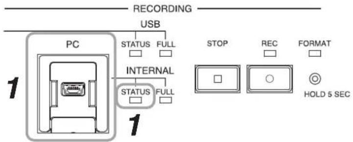
Step 1. Connect a PC to the PC Connection port.
The Internal memory status indicator flashes green, and the USB drive window at right is displayed on the PC screen.

Step 2. Open the "recording" folder.
Step 3. Select the desired sound source and move or copy it to the PC's hard drive.
Important
When disconnecting the PC from the Central unit, be sure to perform "Safe Hardware Removal" using the PC. Please refer to the PC's instruction manual regarding the removal procedure.
Note
Data recorded to the Central unit's internal memory cannot be moved or copied to the connected USB memory device.
[Selecting and deleting an internal memory sound source file]
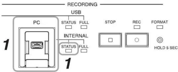
Step 1. Connect a PC to the PC Connection port.
The Internal memory status indicator flashes green, and the USB drive window at right is displayed on the PC screen.

Step 2. Open the "recording" folder.
Step 3. Select the file to be deleted and select "Delete" by right-clicking.
Tip
The file can also be deleted by moving it to the trash box.
[Deleting (formatting) all internal memory sound source files]
All sound source files recorded to the internal memory can be simultaneously deleted by formatting the internal memory.
![TOA TS-920RC - [Deleting (formatting) all internal memory sound source files] - 1](/content/2026/05/1058350/images/80e51cc38e7f3c6d1c06fc53f0dd491d879d1770bffc0f909af90a76cd94db04.jpg)
flowchart
graph TD
    A["MEMORY"] -->|ACCESS| B["Recording"]
    B --> C["USB"]
    C --> D["PC"]
    C --> E["INTERNAL"]
    D --> F["STOP"]
    E --> G["REC FORMAT"]
    E --> H["HOLD 5 SEC"]
    style A fill:#f9f,stroke:#333
    style B fill:#ccf,stroke:#333
    style C fill:#cfc,stroke:#333
    style D fill:#fcc,stroke:#333
    style E fill:#cff,stroke:#333
    style F fill:#ffc,stroke:#333
    style G fill:#cfc,stroke:#333
    style H fill:#fcc,stroke:#333
Step 1. Confirm that no USB memory device is inserted in the USB memory port, and that the Internal Memory status indicator is lit green.
Step 2. Hold down the Format button for 5 seconds or more.
Formatting begins and both the Format in-progress indicator and the Recording status indicator flash red.
When formatting is competed, both the Format in-progress indicator and the Recording status indicator are extinguished.
17. IF ACOUSTIC FEEDBACK OCCURS
An annoying screeching sound may be produced when using a public address system. It is referred to as "Acoustic feedback*" that will occur at various frequencies depending on the surrounding environment.
The TS-920RC's built-in Feedback suppressor (FBS) function effectively suppresses acoustic feedback through simple operation (depresses the volume level at the feedback frequency). If the built-in FBS function cannot deal with the acoustic feedback, an external graphic equalizer (prepare separately) can be used for more effective feedback suppression.
Note
The following measures against acoustic feedback are effective for suppressing feedback only caused by the Conference unit, but not effective for the feedback caused by the external microphone.
If acoustic feedback stops by fully turning down the volume of the external microphone, you will find that the external microphone is the cause of the feedback.
In this case, decrease the external microphone's volume to a level that feedback does not occur or use the external microphone away from the speaker.
* It will occur when a feedback loop is formed in the process that sound from a speaker is picked up by a microphone, re-amplified, and output through the speaker.
17.1. Using the Built-in FBS Function
Note
If acoustic feedback cannot be suppressed with the built-in FBS function, widen the distance between the Chairman unit and Delegate units, reduce the output volume, or use an external graphic equalizer.
(Refer to p. 58.)
Step: Set the Feedback suppressor switch to the AUTO position.
The FBS function automatically searches a frequency that will cause acoustic feedback and suppresses the feedback by decreasing the volume level at such frequency.

17.2. Using an External Graphic Equalizer
Step 1. Connect an external equalizer to the unit as shown below.

Step 2. Set the FBS switch to the EXT position.

Step 3. Take measures against acoustic feedback using the graphic equalizer.
For operation method of the graphic equalizer, read the instruction manual supplied with it.
18. IF A FAILURE IS DETECTED
18.1. Infrared Chairman Unit TS-921/821 and Infrared Delegate Unit TS-922/822
| Symptom Cause | and Points to Check Remedy | |
| Cannot turn ON power. | (When using the lithium-ion battery)Battery not charged. | Batteries are not charged as shipped from the factory. Be sure to fully charge the battery before use.(Refer to p. 37.) |
| (When using the AC adapter)Power cord or DC input plug not connected. | Connect the power cord (supplied with the AC adapter) and the DC input plug correctly. (Refer to p. 38.) | |
| No sound output from the speaker or headphones. | Monitor Selector switch not correctly set. (TS-921/922 only) | Set the switch to the position where sound can be heard. |
| Central unit's Microphone Mix/Cut switch not correctly set. | ||
| Monitor volume control not correctly adjusted. | Adjust the volume to an appropriate level. | |
| Headphone plug not fully inserted. Insert | the headphone plug fully into the jack. | |
| Cannot initiate speech. | Central unit's rear panel-mounted Short circuit indicator remains lit. | Check the cable connected to the Central unit's Infrared transmitter/receiver unit I/O terminals. |
| Live status indicator on the Infrared transmitter/receiver unit remains dark. | ||
| Cannot operate the Talk key. | Unit address numbers outside range of 001 – 192. | Set the unit address number within the range of 001 – 192. (Refer to p. 34.) |
| Infrared emitter/detector exposed to direct sunlight or spotlight. | Reposition in a location not exposed to direct light. (Refer to p. 21.) | |
| Infrared transmitter/receiver units and Conference units not positioned to permit their infrared emitter/detector sections to be in sight of each other.TS-905 or TS-907 Infrared transmitter/receiver units not correctly selected to match the ceiling height and installed so that all the Conference units are in the communications service area.(If both the Power and Speech indicators simultaneously flash, this indicates the unit is out of the communications service area.) | Install all the units so that they are in clear view of each other, and select and install the Infrared/ Transmitter/Receiver units correctly for the ceiling height. (Refer to p. 22.) | |
| Cable between the Infrared transmitter/receiver unit and the Central unit not connected. | Connect the cable. | |
| Priority speech is in progress. Operate the key after the priority speech is completed. | ||
| Indicator on the microphone goes out during speech. | Mic-Off function set to ON. Disable the | Mic-Off function if a long pause is made during speech. |
| Microphone indicator flashes. | Battery voltage has dropped below a marginal level. | Replace the battery with a fully charged one. |
| Chime does not sound when the Priority speech key is pressed. | Central unit's rear panel-mounted Priority Chime volume control is set to the minimum volume position. | Adjust the volume control to an appropriate level. |
| The Priority chime mute switch in the Chairman unit's bottom is set to ON. | Set the Priority chime mute switch to OFF. | |
| Mic-Off function does not work. | High background noise level generated by such equipment as air conditioners. | In areas where the background noise level is high, the Mic-Off function may not work.Reposition in a low-noise location or turn off the Mic-Off function. |
| Battery can be used only for a short period of time. | Not fully charged. Charging is completed | within 5 hours.Note: Fully charged batteries can be used for up to 10 hours.(Refer to p. 37.) |
| Battery is approaching the end of its life. | Use a brand-new battery.Note: Battery can be recharged almost 300 times. | |
18.2. Central Unit TS-920RC
| Symptom Cause | and Points to Check Remedy | |
| Cannot switch ON the power. | Power cord or DC plug not connected. Correctly connect the power cord and DC plug supplied with the Central unit. (Refer to p. 21.) | |
| Recording cannot be made to the USB memory device or otherwise recording stops. | USB memory capacity is insufficient. When its capacity is insufficient, the USB memory remaining capacity warning indicator lights and the USB memory status indicator extinguishes. | Insert a USB memory device that has sufficient remaining capacity, then confirm that the USB memory status indicator lights green before commencing recording. (Refer to p. 50.) |
| USB memory failure. If any failure of the USB memory device is detected, the USB memory status indicator lights red. | Insert a different USB memory device, then confirm that the USB memory status indicator lights green before commencing recording. (Refer to p. 50.) | |
| Recordings cannot be made to the internal memory, or recording otherwise stops. | Remaining internal memory capacity is insufficient. When recording capacity becomes insufficient, the Internal memory remaining capacity warning indicator lights and the Internal memory status indicator extinguishes. | Delete recorded files from the internal memory to create sufficient free space for further recording, then confirm that the Internal memory status indicator lights green before commencing recording. (Refer to p. 51.) |
| Internal memory failure. If any failure of the internal memory is detected, the Internal memory status indicator lights red. | Reformat the internal memory, then confirm that the Internal memory status indicator lights green before commencing recording.NoteFormatting the memory causes all recorded files on it to be deleted. Therefore, it is highly recommended that any necessary files be saved to an external memory device beforehand. (Refer to p. 53.) | |
18.3. Battery Charger BC-900
| Symptom Cause | and Points to Check Remedy | |
| Power indicator (green) does not light even if the power switch is turned ON. | AC plug is not inserted into the wall AC outlet. | Insert the AC plug to the wall AC outlet. |
| Fuse has blown. | The fuse must be replaced.For replacement, consult your TOA dealer. | |
| Charging status indicator (red) does not light even if the lithium-ion battery is inserted into its receptacle. | Lithium-ion battery not correctly inserted into its receptacle. | Insert the lithium ion battery fully into its receptacle. |
| Charging terminals are dirty. | Wipe the terminals with a dry cotton swab to clean them. | |
| Short battery recharge duration. | Deterioration of the lithium-ion battery. | Replace with a brand-new BP-900ALithium-ion battery. |
19. APPENDIX (INFRARED TRANSMITTER/RECEIVER CONNECTION)
This chapter describes how to find the maximum cable length between the Central unit and the Infrared transmitter/receiver unit.
Values calculated here are given only as guidelines, since they can vary depending on ambient building conditions and the Infrared transmitter/receiver unit.
19.1. Wiring Design
19.1.1. Confirming the wiring design
To obtain the maximum cable length between the Infrared transmitter/receiver unit and the Central unit, calculate the cable length on the following each condition. The shorter length of the two results is the required extendable length.
(1) Maximum allowable wiring loss: 20 dB (Total cable and distributor loss)
(2) Maximum allowable DC voltage drop: 5 V
Values necessary for each calculation are as follows.
- Values necessary for calculating the loss
(1) 2-branch distributor (YW-1022) loss: 4.5 dB
(2) 4-branch distributor (YW-1024) loss: 8.5 dB
(3) Coaxial cable loss per 100 m (table shown below)
RG-59/U 3.3 dB
RG-6/U 2.7 dB
RG-11/U
2.0 dB
Note: The values in the table above are losses at 10 MHz.
- Values necessary for calculating the voltage drop
(1) Operating current per Infrared transmitter/receiver unit: 0.1 A (TS-905), 0.13 A (TS-907)
(2) Distributor resistance loss: 0 Ω
(3) Coaxial cable loop resistance per 100 m (table shown below)
RG-59/U 16.82 Ω
RG-6/U 12.82 Ω
RG-11/U 2.4 Ω
Note: The values in the table above are losses at 10 MHz.
Note: Coaxial cable loss and loop resistance values used here are based on our investigation.
19.1.2. Computational equation
• Finding the wiring loss
Requirement: Total loss ≤ 20 dB
Cable loss = (Length / 100) x Loss per 100 m
Total loss = Cable 1 loss + Cable 2 loss + Cable 3 loss + Distributor 1 loss + Distributor 2 loss

flowchart
graph LR
    A["Central Unit"] -->|Coaxial cable 1 loss| B["Distributor 1"]
    B -->|Coaxial cable 2 loss| C["Distributor 2"]
    C -->|Coaxial cable 3 loss| D["Transmitter/Receiver unit"]
• Finding the wiring voltage drop
Requirement: Total voltage drop ≤ 5 V
Cable voltage drop = (Length / 100) x Loop resistance per 100 m x Current
Cable current = Number of the connected Infrared transmitter/receiver units x 0.1 (TS-905) or 0.13 (TS-907)
Total voltage drop = Voltage drop 1 + Voltage drop 2 + Voltage drop 3

flowchart
graph LR
    A["Central unit"] --> B["Distributor"]
    B --> C["Transmitter/Receiver unit"]
    subgraph Central unit
        D["Coaxial cable 1"] --> E["Current 1"]
        E --> F["Voltage drop 1"]
        G["Distributor"] --> H["Coaxial cable 2"]
        H --> I["Current 2"]
        I --> J["Voltage drop 2"]
        K["Distributor"] --> L["Coaxial cable 3"]
        L --> M["Current 3"]
        M --> N["Voltage drop 3"]
    end
Note: For the coaxial cable required to carry a large current, use a cable of low loop resistance type.
[Finding the cable current]
Cable current = Number of the connected Infrared transmitter/receiver units x 0.1 (TS-905) or 0.13 (TS-907) The cable current changes when the Distributor is used, as shown below.
![TOA TS-920RC - [Finding the cable current] - 1](/content/2026/05/1058350/images/0a1c01cfc940cfe23d98ca70d3280302a80e8a319eb9b985d6aa7cdc8a212529.jpg)
flowchart
graph LR
    A["Central unit"] -->|0.1 A| B["Infrared Transmitter/Receiver unit TS-905"]
    C["Central unit"] -->|0.2 A| D["Distributor1"]
    D -->|0.1 A| E["Infrared Transmitter/Receiver units TS-905"]
19.2. Design Examples
19.2.1. Example: When installing 4 TS-905 infrared transmitter/receiver units using 4 coaxial cables reaching from the central unit:

1) Finding the maximum cable length using maximum allowable cable losses
Assuming that the type of coaxial cable used is RG-59/U,
$$ \begin{array}{l} = (2 0 \mathrm{dB} / 3. 3 \mathrm{dB}) \times 1 0 0 \mathrm{m} \ = 6 0 6 \mathrm{m} \ \end{array} $$
Maximum cable length L = (Coaxial cable loss / its cable loss per 100 m)
The following table shows the maximum allowable cable length for each type of coaxial cable.
| RG-59/U 606 | m |
| RG-6/U 740 m | |
| RG -11/ U 1000 | m |
2) Finding the maximum cable length using voltage drop
Since one TS-905 Infrared transmitter/receiver unit is connected per coaxial cable, the current that flows through each coaxial cable is 0.1 A.
Assuming that the type of coaxial cable used is RG-59/U,
$$ \begin{array}{l} = {(5 \mathrm{V} / 0. 1 \mathrm{A}) / 1 6. 8 2 \Omega } \times 1 0 0 \mathrm{m} \ = 2 9 7 \mathrm{m} \ \end{array} $$
Maximum length L = {(Voltage drop 1 / Current 1) / Coaxial cable loop resistance 1 for 100 m}
The following table shows the maximum allowable cable length for each type of coaxial cable.
| RG-59/U 297 | m |
| RG-6/U | 390 m |
| RG -11/U | 2083 m |
The table below shows the required maximum cable length for the example 1, the shorter length of the calculation results (1) and (2) above.
| RG-59/U 297 | m |
| RG-6/U | 390 m |
| RG -11/ U 1000 | m |
19.2.2. Example 2: When installing 4 TS-905 infrared transmitter/receiver units using 1 coaxial cable reaching from the central unit (one 4-branch distributor connected):
Condition: Cable length between the Distributor and the TS-905 Infrared transmitter/receiver unit is assumed to be 50 meters.

1) Finding the maximum cable length using maximum allowable cable losses
Assuming that RG-59/U coaxial cable is used between the Distributor and the Infrared transmitter/receiver unit, the cable loss between the two is calculated by the following equation:
Cable loss = 3.3 dB x (50 m / 100 m) = 1.65 dB
Since the Distributor's internal loss is 8.5 dB, the maximum allowable loss between the Central unit and the Distributor becomes 9.85 dB (20 dB – 1.65 dB – 8.5 dB).
When RG-6/U coaxial cable is used between the Central unit and the Distributor, the length L1 between the two is,
L1 = (Coaxial cable loss / its cable loss per 100 m)
= (9.85dB / 2.7dB)× 100m
= 364 m
Maximum cable length L between the Central unit and the Infrared transmitter/receiver unit is calculated by the following equation:
L = L1 + 50 m
= 364 m + 50 m
= 414 m
Similarly calculated for other types of coaxial cables, the maximum cable length between the Central unit and the Infrared transmitter/receiver unit is found in the following table.
| RG-59/U 348 | m |
| RG-6/U 414 m | |
| RG-11/ U | 542 m |
2) Finding the maximum cable length using voltage drop
The current flowing from the Distributor into each coaxial cable connected to the TS-905 Infrared transmitter/receiver unit is 0.1 A, since the number of Infrared transmitter/receiver units connected to each coaxial cable is 1.
Assuming that RG-59/U coaxial cable is used, the voltage drop between the Distributor and the Infrared transmitter/receiver unit is calculated by the following equation:
$$ \begin{array}{l} \text { Voltage drop } = 1 6. 8 2 \Omega \times (5 0 \mathrm{m} / 1 0 0 \mathrm{m}) \times 0. 1 \mathrm{A} \ = 0. 8 4 1 \mathrm{V} \ \end{array} $$
A remaining voltage of 4.159 V (5 V - 0.841 V) is the maximum allowable voltage drop between the Central unit and the Distributor. The current that flows between the two is 0.4 A.
When RG-6/U coaxial cable is used between the Central unit and the Distributor, the cable length L1 between the two is,
$$ \begin{array}{l} L 1 = \left{\text {(Voltage drop 1 / Current 1) / Coaxial cable loop resistance 1 per 100 m} \right} \ = {(4. 1 5 9 \mathrm{V} / 0. 4 \mathrm{A}) / 1 2. 8 2 \Omega } \times 1 0 0 \mathrm{m} \ = 8 1 \mathrm{m} \ \end{array} $$
Maximum cable length L between the Central unit and the Infrared transmitter/receiver unit is calculated by the following equation:
$$ \begin{array}{l} L = L 1 + 5 0 m \ = 8 1 \mathrm{m} + 5 0 \mathrm{m} \ = 1 3 1 \mathrm{m} \ \end{array} $$
Similarly calculated for other types of coaxial cables, the maximum cable length between the Central unit and the Infrared transmitter/receiver unit is found in the following table.
| RG-59/U 111 m | |
| RG-6/U 131 m | |
| RG -11/U | 483 m |
The table below shows the required maximum cable length for the example 2, the shorter length of the calculation results (1) and (2) above.
| RG-59/U | 111 m |
| RG-6/U | 131 m |
| RG -11/ U | 483 m |
19.2.3. Example 3: When installing each 4 TS-905 infrared transmitter/receiver units using 4 coaxial cables reaching from the central unit (four 4-branch distributors connected):
Condition: Cable length between the Distributor and the TS-905 Infrared transmitter/receiver unit is assumed to be 50 meters.

flowchart
graph TD
    A["Central unit"] --> B["Distributor 1"]
    A --> C["Distributor 4"]
    B --> D["Infrared Transmitter/Receiver units TS-905"]
    C --> D
    B -.->|dotted| C
    C -.->|dotted| B
    style A fill:#f9f,stroke:#333
    style B fill:#ccf,stroke:#333
    style C fill:#ccf,stroke:#333
The equation and maximum cable length in this example are the same as those in Example 2 in the previous section on p. 61.
19.2.4. Example 4: When installing 16 TS-905 infrared transmitter/receiver units using 1 coaxial cable reaching from the central unit (five 4-branch distributors connected):
Condition: Length between the Distributor 2 and the TS-905 Infrared transmitter/receiver unit is assumed to be 50 meters, and the length between Distributor 1 and Distributor 2 10 meters.

flowchart
graph LR
    A["Infrared Transmitter/Receiver Units TS-905"] --> B["Distributor 2"]
    B --> C["2 Central Unit"]
    B --> D["5 Central Unit"]
    C --> E["Infrared Transmitter/Receiver Units TS-905"]
    D --> F["Infrared Transmitter/Receiver Units TS-905"]
    style A fill:#f9f,stroke:#333
    style B fill:#ccf,stroke:#333
    style C fill:#cfc,stroke:#333
    style D fill:#fcc,stroke:#333
    style E fill:#ffc,stroke:#333
    style F fill:#fcc,stroke:#333
1) Finding the maximum length using maximum allowable cable losses
Assuming that RG-59/U coaxial cable is used, the cable loss between the Distributor 2 and the Infrared transmitter/receiver unit is calculated by the following equation:
Cable loss = 3.3 dB x (50 m / 100 m) = 1.65 dB
Assuming that RG-6/U coaxial cable is used, the cable loss between the Distributor 1 and Distributor 2 is calculated by the following equation:
Cable loss = 2.7 dB x (10 m / 100 m) = 0.27 dB
Because of the 2 serially-connected 4-branch distributors, their loss is 17 dB (8.5 dB + 8.5 dB), which is added to the above cable loss, causing a total loss of 18.92 dB (1.65 dB + 0.27 dB + 17 dB). Therefore, the maximum allowable cable loss between the Central unit and the Distributor 1 is calculated to be 1.08 dB (20 dB - 18.92 dB).
- Assuming that RG-11/U coaxial cable is used, L1 between the Central unit and the Distributor 1 is calculated by the following equation:
$$ \begin{array}{l} = (1. 0 8 \mathrm{dB} / 2 \mathrm{dB}) \times 1 0 0 \mathrm{m} \ = 5 4 \mathrm{m} \ \end{array} $$
L1 = (Coaxial cable loss / its cable loss per 100 m)
Maximum cable length L (Length between the Central unit and the Infrared transmitter/receiver unit)
$$ = 5 4 \mathrm{m} + 1 0 \mathrm{m} + 5 0 \mathrm{m} = 1 1 4 \mathrm{m} $$
- Assuming that RG-6/U coaxial cable is used, L1 between the Central unit and the Distributor 1 is calculated by the following equation:
$$ \begin{array}{l} = (1. 0 8 \mathrm{dB} / 2. 7 \mathrm{dB}) \times 1 0 0 \mathrm{m} \ = 4 0 \mathrm{m} \ = 4 0 \mathrm{m} + 1 0 \mathrm{m} + 5 0 \mathrm{m} = 1 0 0 \mathrm{m} \ \end{array} $$
L1 = (Coaxial cable loss / its cable loss per 100 m)
Maximum cable length L (Length between the Central unit and the Infrared transmitter/receiver unit)
Similarly calculated for other types of coaxial cables, the maximum cable length between the Central unit and the Infrared transmitter/receiver unit is found in the table.
| RG-59/U 92 | m |
| RG-6/U 100 | m |
| RG-11/U 114 | m |
2) Finding the maximum cable length using voltage drop
The current flowing from the Distributor 2 into each coaxial cable connected to the TS-905 Infrared transmitter/receiver unit is 0.1 A, since the number of Infrared transmitter/receiver units connected to each coaxial cable is 1.
Assuming that RG-59/U coaxial cable is used, the voltage drop between the Distributor 2 and the Infrared transmitter/receiver unit is calculated by the following equation:
$$ \begin{array}{l} \text { Voltage drop } = 1 6. 8 2 \Omega \times (5 0 \mathrm{m} / 1 0 0 \mathrm{m}) \times 0. 1 \mathrm{A} \ = 0. 8 4 1 \mathrm{V} \ \end{array} $$
When RG-6/U type coaxial cable is used, since the current flowing into each coaxial cable between Distributor 1 and Distributor 2 is 0.4 A, the voltage drop between the two is calculated by the following equation:
$$ \begin{array}{l} \text { Voltage drop } 2 = 1 2. 8 2 \Omega \times (1 0 \mathrm{m} / 1 0 0 \mathrm{m}) \times 0. 4 \mathrm{A} \ = 0. 5 1 3 \mathrm{V} \ \text { Voltage drop } 1 + \text { Voltage drop } 2 = 1. 3 5 4 \mathrm{V} \ \end{array} $$
A remaining voltage of 3.646 V (5 V – 1.354 V) is the maximum allowable voltage drop between the Central unit and the Distributor 1. The current that flows between the two is 1.6 A.
- Assuming that RG-11/U coaxial cable is used, L1 between the Central unit and the Distributor 1 is calculated by the following equation:
$$ \begin{array}{l} L 1 = \left{\text {(Voltage drop 1 / Current 1) / Coaxial cable loop resistance 1 per 100 m} \right} \ = {(3. 6 4 6 \mathrm{V} / 1. 6 \mathrm{A}) / 2. 4 \Omega } \times 1 0 0 \mathrm{m} \ = 9 4 \mathrm{m} \ = 9 4 \mathrm{m} + 1 0 \mathrm{m} + 5 0 \mathrm{m} = 1 5 4 \mathrm{m} \ \end{array} $$
Maxim cable length L (Length between the Central unit and the Infrared transmitter/receiver unit)
- Assuming that RG-6/U coaxial cable is used, L1 between the Central unit and the Distributor 1 is calculated by the following equation:
$$ \begin{array}{l} \mathrm{L1} = {\text {(Voltage drop 1 / Current 1) / Coaxial cable loop resistance 1 per 100 m} } \ = {(3. 6 4 6 \mathrm{V} / 1. 6 \mathrm{A}) / 1 2. 8 2 \Omega } \times 1 0 0 \mathrm{m} \ = 1 7 \mathrm{m} \ \end{array} $$
Maxim cable length L (Length between the Central unit and the Infrared transmitter/receiver unit)
$$ = 1 7 \mathrm{m} + 1 0 \mathrm{m} + 5 0 \mathrm{m} = 7 7 \mathrm{m} $$
Similarly calculated for other types of coaxial cables, the maximum cable length between the Central unit and the Infrared transmitter/receiver unit is found in the following table.
| RG-59/U 73 m |
| RG-6/U 77 m |
| RG -11/U 154 m |
The table below shows the required maximum cable length for the example 4, the shorter length of the calculation results (1) and (2) above.
| RG-59/U 73 m |
| RG-6/U 77 m |
| RG -11/U 114 m |
20. SIGNAL FLOW DIAGRAM INSIDE THE CENTRAL UNIT

flowchart
graph TD
    A["Translation language Base language LINE REC OUT"] --> B["MIC 1 input"]
    A --> C["AUX 1 input"]
    A --> D["MIC 2 input"]
    A --> E["AUX 2 input"]
    A --> F["AUX 3 input"]
    G["Audio signal from Conference units"] --> H["CUT MIX"]
    G --> I["CUT MIX"]
    G --> J["Microphone Mix/Cut switch (for translation language)"]
    K["Inter-locking"] --> L["Microphone Mix/Cut switch (for base language)"]
    M["AUX 3 output Mix/Cut switch (for base language)"] --> N["CUT MIX"]
    M --> O["AUX 3 output Mix/Cut switch (for base language)"]
    P["Recording output"] --> Q["Line output"]
    R["Base language"] --> S["Translation language"]
    T["Note*"] --> U["Output"]
* Sent to each Conference unit via Infrared Transmitter/Receiver.
21. SPECIFICATIONS
21.1. Central Unit TS-920RC
| Power Source 100 - 240 V AC | 50/60 Hz (use of the supplied AC adapter) |
| Power Consumption 72 W | |
| Current Consumption Max. 3 A | DC (when 24 V DC is supplied from the supplied AC adapter) |
| Current Frequency Reception: | Audio channel 1: 7.35 MHzAudio channel 2: 8.10 MHzAudio channel 3: 8.55 MHzAudio channel 4: 9.15 MHzControl channel: 6.45 MHzTransmission: Base language channel: 1.95 MHzTranslation language channel: 2.25 MHz |
| Input | MIC 1 (Base Language):-60 dB*1, 600 Ω, unbalanced, ø6.3 mm phone jack (2P)MIC 2 (Translation Language):-60 dB*1, 600 Ω, unbalanced, ø6.3 mm phone jack (2P)AUX 1 (Base Language):-20 dB*1, 10 kΩ, unbalanced, ø6.3 mm phone jack (2P)AUX 2 (Translation Language):-20 dB*1, 10 kΩ, unbalanced, ø6.3 mm phone jack (2P)AUX 3 (Bass and Translation Language):-20 dB*1, 10 kΩ, unbalanced, ø6.3 mm phone jack (2P) |
| Output | LINE: -10 dB*, 10 kΩ, unbalanced, ø6.3 mm phone jack (2P)REC: -10 dB*, 10 kΩ, unbalanced, RCA pin jackHEADPHONES: ø3.5 mm mini jack (3P: monaural) |
| Equalizer Input/Output | Input: -20 dB*, 10 kΩ, unbalanced, RCA pin jackOutput: -20 dB*, 10 kΩ, unbalanced, RCA pin jack |
| Number of Connectable Chairman/Delegate Units | 192 units |
| Number of Connectable Infrared Transmitter/Receiver Units | Up to 4 units (with the use of distributor, up to 16 units connectable when they are all TS-905, and up to 12 units when they are all TS-907, or TS-905 and TS-907 are used in combination) |
| Infrared Transmitter/Receiver I/O Terminal | BNC jack |
| External Control Connection Terminal | D-sub connector (9P, male)/USB-B selectable |
| LED Indicator | Voting result indicators 1 - 3 (7-segment LED, 3 digits), Short-circuit indicator, Audio signal receiving indicators 1 - 4 CH, Data signal receiving indicator, External control priority indicator, External control communication indicator, Battery indicator (flashes when a Chairman/Delegate unit's battery nears complete discharge), Recording status indicator, Format in-progress indicator, Access indicator, Internal memory status indicator, USB memory status indicator, Remaining internal memory capacity warning indicator, Remaining USB memory capacity warning indicator |
| Record Switch | Recording start button, Recording stop button, Format button |
| Recording Ports | USB-A (for USB memory devices) and USB Mini-B (for PCs) |
| Recording Function Recordings | can be made to a USB memory device*2or the internal memory.Recording format: MP3 (MPEG-1 Audio Layer-3), monauralSampling frequency: 32 kHz, Bit rate: 128 kbps |
| Function Switch | Number of open microphones setting switch: 1/2/3/4Mic-off setting switch: TIME OUT ON/OFFSpeech priority selector switch:FIRST (First-in-first-out priority),LATEST (Last-in-first-out priority),FIRST:FIXED NEXT:LATEST (Priority fixed for the first unit, and last-in-first-out priority for all other subsequent units.)FBS switch: AUTO/OFF/EXT |
| Operating Temperature | 0 to 40 °C (32 to 104 °F) |
| Operating Humidity | 90%RH or less (no condensation) |
| Finish Panel: Surface-treated steel plate, black, 30% glossy, paint | |
| Dimensions | 361 (w) x 122.6 (h) x 184.2 (d) mm (14.21" x 4.83" x 7.25") |
| Weight | 2.8 kg (6.17 lb) |
*1 0 dB = 1 V
*2 For usable USB memory devices, see p. 49.
Note: The design and specifications are subject to change without notice for improvement.
- Accessory
AC adapter (DC cord: 1.8 m or 5.91 ft, Detachable AC cord: 2 m or 6.56 ft) ..... 1
21.2. Infrared Chairman Unit TS-921, Infrared Delegate Unit TS-922
| Model No. TS-921 | TS-922 | ||
| Power Source 7.2 V DC (supplied from optional lithium-ion battery),9 V DC (supplied from optional AC adapter) | |||
| Current Consumption Max. 390 mA | |||
| Infrared Emitter/Detector | Wavelength 870 nm (AM: Brightness modulation) | ||
| Modulation Method Frequency modulation | |||
| Carrier Frequency Transmission: Audio channel 1: 7.35 MHzAudio channel 2: 8.10 MHzAudio channel 3: 8.55 MHzAudio channel 4: 9.15 MHzControl channel: 6.45 MHzReception: Base language channel: 1.95 MHzTranslation language channel: 2.25 MHz | |||
| Covering Range | 7 m or 22.97 ft (radius) | ||
| Input | Microphone terminal: XLR-4-31 type | ||
| Output | Monitor speaker: 8 Ω, 0.2 WHeadphones: ø3.5 mm mini jack (3P: monaural) x 2 | ||
| LED Indicator | Speech indicator, Voting status indicators 1 – 3, Power indicator | ||
| Function | Monitor volume controlHeadphone volume controlPriority speech functionVoting functionMonitor selector switch (MAIN/SUB) | Monitor volume controlHeadphone volume controlVoting functionMonitor selector switch (MAIN/SUB) | |
| Battery Life | Approx. 10 hours | ||
| Operating Temperature | 0 to 40 °C (32 to 104 °F) | ||
| Operating Humidity | 90%RH or less (no condensation) | ||
| Finish | Case: PC resin, blackSpeaker net: black, mat finish, paint | ||
| Dimensions | 205.7 (w) x 70.3 (h) x 164.2 (d) mm (8.1" x 2.77" x 6.46") | ||
| Weight | 525 g (1.16 lb) | ||
Note: The design and specifications are subject to change without notice for improvement.
21.3. Infrared Chairman Unit TS-821, Infrared Delegate Unit TS-822
| Model No. TS-821 | TS-822 | ||
| Power Source 7.2 V DC (supplied from optional lithium-ion battery),9 V DC (supplied from optional AC adapter) | |||
| Current Consumption Max. 390 mA | |||
| Infrared Emitter/Detector | Wavelength 870 nm (AM: Brightness modulation) | ||
| Modulation Method Frequency modulation | |||
| Carrier Frequency Transmission: Audio channel 1: 7.35 MHzAudio channel 2: 8.10 MHzAudio channel 3: 8.55 MHzAudio channel 4: 9.15 MHzControl channel: 6.45 MHzReception: Audio channel: 1.95 MHz | |||
| Covering Range | 7 m or 22.97 ft (radius) | ||
| Input | Microphone terminal: XLR-4-31 type | ||
| Output | Monitor speaker: 8 Ω, 0.2 WHeadphones: ø3.5 mm mini jack (3P: monaural) x 2 | ||
| LED Indicator | Speech indicator, Power indicator | ||
| Function | Monitor volume controlHeadphone volume controlPriority speech function | Monitor volume controlHeadphone volume control | |
| Battery Life | Approx. 10 hours | ||
| Operating Temperature | 0 to 40 °C (32 to 104 °F) | ||
| Operating Humidity | 90%RH or less (no condensation) | ||
| Finish | Case: PC resin, blackSpeaker net: black, mat finish, paint | ||
| Dimensions | 205.7 (w) x 70.3 (h) x 164.2 (d) mm (8.1" x 2.77" x 6.46") | ||
| Weight | 525 g (1.16 lb) | ||
Note: The design and specifications are subject to change without notice for improvement.
21.4. Microphone (standard) TS-923, Microphone (long) TS-924
| Model No. TS-923 | TS-924 | |
| Type | Electret condenser microphone | |
| Directivity Unidirectional | ||
| Rated Impedance 1.4 kΩ | ||
| Rated Sensitivity | -37 dB (1 kHz, 0 dB = 1 V/Pa) | |
| LED Indicator Speech indicator (ring type), red | ||
| Frequency Response 100 Hz – 13 kHz | ||
| Output Connector Combined type of XLR-4-32 | ||
| Flexible Part 2 parts | ||
| Operating Temperature 0 to 40 °C (32 to 104 °F) | ||
| Operating Humidity 90%RH or less (no condensation) | ||
| Finish | Body: Aluminum, black, semi-glossy, paintShaft: Copper alloy, black, semi-glossy, paint | |
| Length | 470 mm (1.54 ft) | 620 mm (2.03 ft) |
| Weight | 130 g (0.29 lb) | 150 g (0.33 lb) |
| Applicable Unit (Option) | Chairman unit: TS-821, TS-921, TS-811, TS-911Delegate unit: TS-822, TS-922, TS-812, TS-912 | |
Note: The design and specifications are subject to change without notice for improvement.
21.5. Infrared Transmitter/Receiver TS-905, TS-907
| Model No. TS-905 | TS-907 | ||
| Power Source | 24 V DC (supplied from the optional TS-920RC) | ||
| Current Consumption | Max. 150 mA | Max. 180 mA | |
| Infrared Emitter/Detector | Wavelength | 870 nm (AM: Brightness modulation) | |
| Modulation Method | Frequency modulation | ||
| Carrier Frequency | Transmission: Audio channel 1: 7.35 MHzAudio channel 2: 8.10 MHzAudio channel 3: 8.55 MHzAudio channel 4: 9.15 MHzControl channel: 6.45 MHzReception: Base language channel: 1.95 MHzTranslation language channel: 2.25 MHz | ||
| Acceptance Angle | Vertical: 150°(75°+75°), Horizontal: 360° | Vertical: 90°(45°+45°), Horizontal: 360° | |
| Emission Angle | Vertical: 150°(75°+75°), Horizontal: 360° | Vertical: 90°(45°+45°), Horizontal: 360° | |
| Communication Area | Approx. 6 – 7 m (19.69 – 22.97 ft) in radius from the point underneath the unit (Ceiling height: 2.5 – 4.5 m or 8.2 – 14.76 ft) | Approx. 6 m (19.69 ft) in radius from the point underneath the unit (Ceiling height: 5 – 7 m or 16.4 – 22.97 ft) | |
| Connection Terminal | BNC jack | ||
| LED Indicator | Power | ||
| Operating Temperature 0 | to 40 °C (32 to 104 °F) | ||
| Operating Humidity 90%RH or less (no condensation) | |||
| Finish | Dome: PC resin, visible light cut filterBase: ABS resin, black | ||
| Dimensions | ø120 x 71.3 (h) mm (ø4.72" x 2.81") | ||
| Weight | 230 g or 0.51 lb (unit only) | ||
Note: The design and specifications are subject to change without notice for improvement.
- Accessories
Mounting bracket 1
Stand mounting bracket 1
Screw M3 x 6 3
U5/16 – NS5/8 thread adapter (except for TS-905 CE version) ..... 1
21.6. Lithium-Ion Battery BP-900A
| Nominal Voltage 7.2 V DC | |
| Nominal Capacity 2100 mAh | |
| Operating Temperature 0 to 40 °C (32 to 104 °F) | |
| Operating Humidity 90%RH or less (no condensation) | |
| Dimensions 71.6 (w) x 20.5 (h) x 37.5 (d) mm (2.82" x 0.81" x 1.48") | |
| Weight 95 g (0.21 lb) | |
Note: The design and specifications are subject to change without notice for improvement.
21.7. Battery Charger BC-900
| Power Source 100 – 240 | V AC, 50/60 Hz (use of the supplied AC adapter) |
| Current Consumption Max. | 5 A DC |
| Charging Time Approx. 5 hours | |
| Charging Capacity 8 BP-900A batteries (option) | |
| LED Indicator Charging status (Green: Full charge, Red: On charge), Power indicator | |
| Operating Temperature 0 to 40 °C (32 to 104 °F) | |
| Operating Humidity 90%RH or less (no condensation) | |
| Finish | Case: Steel, black, paintBattery receptacles: PPO resin, black |
| Dimensions 240 (w) x 70 (h) x 115 (d) mm (9.45" x 2.76" x 4.53") | |
| Weight Unit: 1.2 kg (2.65 lb), AC adapter: 520 g (1.15 lb) | |
Note: The design and specifications are subject to change without notice for improvement.
- Accessory
AC adapter (DC cord: 1.5 m or 4.92 ft, Detachable AC cord: 2 m or 6.56 ft) ..... 1
21.8. AC Adapter AD-0910
| Power Source 100 – 240 | V AC, 50/60 Hz |
| Output 9 V DC, 1 A | |
| Ripple Voltage | 100 mV (p-p) |
| Current Consumption 400 | mA AC, Input 100 V |
| Cord Length | 1.8 m (5.91 ft) |
| Plug | RC6705, center "+" |
| Operating Temperature 0 | to 40 °C (32 to 104 °F) |
| Operating Humidity 90%RH or less (no condensation) | |
| Finish | Case: PC/ABS alloy, black |
| Dimensions | 47.4 (w) x 33 (h) x 86.5 (d) mm or 1.87" x 1.3" x 3.41" (excluding a power cord) |
| Weight 190 g (0.42 lb) | |
Note: The design and specifications are subject to change without notice for improvement.
- Accessory
AC power cord (2 m or 6.56 ft) .... 1
21.9. Distributor YW-1022 (2-branch distributor), YW-1024 (4-branch distributor)
| Model No. YW-1022 | YW-1024 | |
| Frequency Range 1.6 – 1 | 1000 MHz (excluding 50 – 70 MHz) | |
| Distribution Loss 4.5 dB ±3 dB (between the Mixing and each Distribution terminals) | 8.5 dB ±3 dB (between the Mixing and each Distribution terminals) | |
| Input/Output Impedance | 75 Ω | |
| Coaxial Connector Mixing terminal: BNC jack, power passing type (30 V DC or less, 2 A or less) Distribution 1 and 2 terminals: BNC jack, power passing type (30 V DC or less, 1 A or less) | Mixing terminal: BNC jack, power passing type (30 V DC or less, 2 A or less) Distribution 1 – 4 terminals: BNC jack, power passing type (30 V DC or less, 1 A or less) | |
| Operating Temperature –10 to +50 °C (14 to 122 °F) | ||
| Operating Humidity 90%RH or less (no condensation) | ||
| Finish | ABS resin, gray | |
| Dimensions 75 (w) x 122 (h) x 34 (d) mm (2.95" x 4.8" x 1.34") | ||
| Weight 105 g (0.23 lb) | 120 g (0.26 lb) | |
Note: The design and specifications are subject to change without notice for improvement.
- Accessories
Wood screw 4.1 x 25 (for fixing the unit) ... 2
21.10. Rack Mounting Bracket MB-TS920
| Finish Surface-treated steel plate, black, paint, 30% glossy |
| Dimensions 65.5 (w) x 177 (h) x 61 (d) mm (2.58" x 6.97" x 2.4") |
| Weight 680 g (1.5 lb) |
Note: The design and specifications are subject to change without notice for improvement.
- Accessories
Rack mounting screw 5 x 12 .... 4
Fiber washer (for M5) 4
| Traceability Information for Europe | |
| Manufacturer:TOA Corporation7-2-1, Minatojima-Nakamachi, Chuo-ku, Kobe, Hyogo, Japan | Authorized representative:TOA Electronics Europe GmbHSuederstrasse 282, 20537 Hamburg, Germany |
URL: https://www.toa.jp/

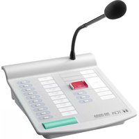
- CONFERENCE SYSTEM TS-920 SERIES
- TABLE OF CONTENTS
- IF ACOUSTIC FEEDBACK OCCURS 54
- IF A FAILURE IS DETECTED 55
- APPENDIX (INFRARED TRANSMITTER/RECEIVER CONNECTION) 58
- SIGNAL FLOW DIAGRAM INSIDE THE CENTRAL UNIT 66
- SPECIFICATIONS 67
- SAFETY PRECAUTIONS
- Safety Symbol and Message Conventions
- DANGER
- When the Unit is in Use
- Applicable to Lithium-ion battery
- WARNING
- When Installing the Unit
- Applicable to Central unit, Conference unit, Battery charger, and AC adapter
- Applicable to Battery charger and Lithium-ion battery
- Applicable to Central unit and Conference unit
- CAUTION
- Applicable to Central unit
- Applicable to Central unit, Conference unit, and Battery charger
- Applicable to Conference unit
- Applicable to Battery charger
- GENERAL DESCRIPTION
- FEATURES
- [Conference unit]
- NOMENCLATURE AND FUNCTIONS
- Central Unit TS-920RC
- Power switch [POWER]
- Access indicator (green) [ACCESS]
- Note
- Data signal receiving indicator [DATA]
- Audio signal receiving indicators
- [MIC UNIT, CH1/CH2/CH3/CH4]
- Battery indicator [BATTERY]
- External control priority indicator [EXT, PRIORITY]
- External control communication indicator [EXT, DATA]
- Number of open microphones setting switch [MAX MIC UNIT, 1/2/3/4]
- Speech priority selector switch [PRIORITY]
- Mic-off setting switch [AUTO OFF]
- MIC 1 input volume control [MAIN, MIC 1]
- Microphone Mix/Cut switch (for the base language channel) [MAIN, MIX/CUT]
- AUX 1 input volume control [MAIN, AUX 1]
- Microphone Mix/Cut switch
- (for the translation language channel) [SUB, MIX/CUT]
- AUX 2 input volume control [SUB, AUX 2]
- MIC 2 input volume control [SUB, MIC 2]
- AUX 3 input volume control [MAIN+SUB, AUX 3]
- Headphone channel selector switch [MAIN/SUB/LINE]
- USB memory port [MEMORY]
- PC connection port (USB Mini-B) [PC]
- Internal memory status indicator (green/red) [INTERNAL, STATUS]
- Remaining internal memory capacity warning indicator (orange) [INTERNAL, FULL]
- USB memory status indicator (green/red) [USB, STATUS]
- Remaining USB memory capacity warning indicator (orange) [USB, FULL]
- Recording stop button [STOP]
- Recording start button [REC]
- Recording status indicator (red) [REC]
- Format button [HOLD 5 SEC]
- Format in-progress indicator (red) [FORMAT]
- Voting start/end button [START/END]
- Vote result monitor [VOTING]
- Speech volume control [MIC UNIT]
- Headphone jack [Ω]
- Headphone volume control [HEADPHONES]
- FBS (Feedback Suppressor) switch [FBS, AUTO/OFF/EXT]
- AUX 3 input terminal [AUX 3]
- AUX 2 input terminal [AUX 2]
- MIC 2 input terminal [MIC 2]
- AUX 1 input terminal [AUX 1]
- MIC 1 input terminal [MIC 1]
- External control terminal [RS-232C]
- External control terminal selection switch
- External control terminal [USB]
- Level volume control [LINE OUT, LEVEL]
- Line output terminal [LINE OUT]
- AUX 3 output Mix/Cut switch [LINE OUT, MIX/CUT, AUX 3]
- Recording output terminal [REC OUT]
- Graphic equalizer input terminal [EQUALIZER, IN]
- Graphic equalizer output terminal [EQUALIZER, OUT]
- Priority chime volume control [CHIME]
- DC inlet
- 52.Cableclip
- Short circuit indicator [SHORT]
- Infrared transmitter/receiver I/O terminals [INFRARED TRANSMITTER/RECEIVER]
- Functional ground terminal [SIGNAL GND]
- Infrared Chairman Units TS-921 and TS-821
- Infrared emitter/detector
- Monitor speaker
- Speech indicator
- Voting keys (TS-921 only)
- Talk key
- Priority speech key
- Power indicator [POWER]
- Microphone
- Microphone in-use indicator
- 10.DCinlet
- Power switch
- Lithium-ion battery compartment
- Release key
- Priority operation setting switch
- Priority chime mute switch
- Voting activation switch (TS-921 only)
- Priority speech key operation setting switch
- Unit address number setting switch
- Rating nameplate
- Monitor volume control
- Headphone jack
- Monitor selector switch (TS-921 only)
- Headphone volume control
- Infrared Delegate Units TS-922 and TS-822
- [TS-922 Top] [TS -822 Top]
- Microphone in-use indicator
- Voting keys (TS-922 only)
- Power indicator
- Microphone
- Speech indicator
- [Rear]
- DC inlet
- Power switch
- [Bottom]
- Lithium-ion battery compartment
- Releasekey
- Unit address number setting switch
- Rating nameplate
- [Right side]
- Monitor volume control
- Headphonejack
- Monitor selector switch (TS-922 only)
- [Left side]
- Headphone volume control
- INFRARED TRANSMITTER/RECEIVER INSTALLATION AND CONNECTIONS
- Notes on Installation of the Infrared Transmitter/Receiver Unit
- [Avoid direct sunlight]
- [Keep away from fluorescent lights]
- [Keep away other infrared light sources]
- Infrared Service Areas
- Infrared transmitter/receiver
- Notes
- Infrared conference unit
- Infrared Transmitter/Receiver Arrangement Examples
- [Conference room measuring 30 x 30 meters]
- [Conference room using round tables]
- Wiring between the Infrared Transmitter/Receiver Unit and the Central Unit
- Notes on wiring
- Using the distributor
- Wiring examples
- Mounting the Infrared Transmitter/Receiver Unit
- Ceiling mounting
- Mounting on a microphone stand
- Connections between the Infrared Transmitter/Receiver Unit and the Central Unit
- Connecting
- Coaxial cable processing
- Attaching a YA-641 or CC-4901 BNC Plug to the RG-59/U Cable
- Attaching a YA-641 BNC Plug to the RG-6/U Cable
- Attaching a YA-642 BNC Plug to the RG-11/U Cable
- USING WIRED MICROPHONES AND SOUND SOURCE EQUIPMENT
- Wired Microphone Use
- Sound Source Equipment Use
- RECORDING EQUIPMENT CONNECTION
- CONFERENCE UNIT INSTALLATION AND SETTINGS
- INFRARED CONFERENCE UNIT POWER SUPPLY
- BP-900A Lithium-Ion Battery
- Inserting the lithium-ion battery
- Recharging
- AD-0910 AC Adapter
- MOUNTING THE CENTRAL UNIT ON A RACK
- INSTALLATION STATUS CONFIRMATION
- FUNCTION SETTINGS
- Setting the Maximum Number of Open Microphones
- Speech Priority Settings
- First-in/first-out priority
- Last-in/first-out priority (LATEST)
- Priority fixed for first-enabled unit, and last-in/first-out priority for all subsequent units (FIRST: FIXED, NEXT: LATEST)
- Mic-Off Function
- MICROPHONE MIX/CUT SWITCH SETTINGS
- [Switch setting relationship of input to base/translation language channel]
- OPERATION
- Initiating Speech
- Initiating Priority Speech (TS-921 and TS-821 only)
- When the Priority speech key is set to PTT type (Factory-preset)
- Step 1. Speak while holding down the Priority speech key.
- Step 2. Release the Priority speech key after speech completion.
- When the Priority speech key is set to ALT type
- Step 1. Press the Priority speech key.
- Step 2. Speak into the microphone.
- Step 3. Press the Priority speech key again after speech completion.
- Voting (TS-921 and TS-922 only)
- Step 1. Set the unit to Vote reception mode.
- Step 2. Vote.
- Tips
- Step 3. Terminate voting.
- Step 4. Clear the Voting result display.
- Using the Recording Function
- Notes on use
- Important
- Usable USB memory devices
- Sound source file specifications and filenames
- Example
- [Time Setting and Confirmation]
- Recording to a USB memory device
- [Procedure for recording to a USB memory device]
- Tip
- [Moving a sound source file from the USB memory device]
- [Selecting sound source files on the USB memory device and deleting them]
- Recording to the internal memory
- [Procedure for recording to the internal memory]
- [Moving sound source files from the internal memory]
- Step 1. Connect a PC to the PC Connection port.
- Step 2. Open the "recording" folder.
- Step 3. Select the desired sound source and move or copy it to the PC's hard drive.
- [Selecting and deleting an internal memory sound source file]
- Step 3. Select the file to be deleted and select "Delete" by right-clicking.
- [Deleting (formatting) all internal memory sound source files]
- Step 1. Confirm that no USB memory device is inserted in the USB memory port, and that the Internal Memory status indicator is lit green.
- Step 2. Hold down the Format button for 5 seconds or more.
- IF ACOUSTIC FEEDBACK OCCURS
- Using the Built-in FBS Function
- Using an External Graphic Equalizer
- IF A FAILURE IS DETECTED
- Central Unit TS-920RC
- Battery Charger BC-900
- APPENDIX (INFRARED TRANSMITTER/RECEIVER CONNECTION)
- Wiring Design
- Confirming the wiring design
- Computational equation
- [Finding the cable current]
- Design Examples
- Example: When installing 4 TS-905 infrared transmitter/receiver units using 4 coaxial cables reaching from the central unit:
- 1) Finding the maximum cable length using maximum allowable cable losses
- 2) Finding the maximum cable length using voltage drop
- Example 2: When installing 4 TS-905 infrared transmitter/receiver units using 1 coaxial cable reaching from the central unit (one 4-branch distributor connected):
- Example 3: When installing each 4 TS-905 infrared transmitter/receiver units using 4 coaxial cables reaching from the central unit (four 4-branch distributors connected):
- Example 4: When installing 16 TS-905 infrared transmitter/receiver units using 1 coaxial cable reaching from the central unit (five 4-branch distributors connected):
- 1) Finding the maximum length using maximum allowable cable losses
- SIGNAL FLOW DIAGRAM INSIDE THE CENTRAL UNIT
- SPECIFICATIONS
- - Accessory
- Infrared Chairman Unit TS-921, Infrared Delegate Unit TS-922
- - Accessories
- Lithium-Ion Battery BP-900A
- Battery Charger BC-900
- AC Adapter AD-0910
- Distributor YW-1022 (2-branch distributor), YW-1024 (4-branch distributor)
- Rack Mounting Bracket MB-TS920
Brand : TOA
Model : TS-920RC
Category : Microphone