ALF-PA100V - Blender Alfatron - Free user manual and instructions
Find the device manual for free ALF-PA100V Alfatron in PDF.


| Product Type | Blender |
| Brand | Alfatron |
| Model | ALF-PA100V |
| Power | 600 W |
| Capacity | 1.5 L |
| Jug Material | Tritan plastic (BPA-free) |
| Blade Material | Stainless steel |
| Speeds | 2 speeds + pulse |
| Functions | Blending, pureeing, crushing ice |
| Non-slip Feet | Yes |
| Cord Length | 1.2 m |
| Dimensions (H x W x D) | 40 x 18 x 18 cm |
| Weight | 1.8 kg |
| Power Supply | 220-240 V, 50/60 Hz |
| Overheat Protection | Yes (auto shut-off) |
| Cleaning | Jug and lid are dishwasher safe; blade unit rinse only |
| Safety Lock | Locking lid mechanism |
| Warranty | 2 years |
Frequently Asked Questions - ALF-PA100V Alfatron
User questions about ALF-PA100V Alfatron
0 question about this device. Answer the ones you know or ask your own.
Ask a new question about this device
Download the instructions for your Blender in PDF format for free! Find your manual ALF-PA100V - Alfatron and take your electronic device back in hand. On this page are published all the documents necessary for the use of your device. ALF-PA100V by Alfatron.
USER MANUAL ALF-PA100V Alfatron
PA100V 40W Power Amplifier
USER MANUAL
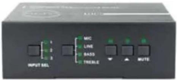
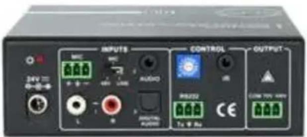
All Rights Reserved
Version: PA100V_2016V1.0
Safety Operation Guide
In order to guarantee the reliable operation of the equipment and safety of the staff, please abide by the following in installation, using and maintenance:
1) The system must be earthed properly. Please do not use two blade plugs and ensure the alternating power supply ranged from 100v to 240v and from 50Hz to 60Hz.
2) Do not put the switcher in extreme temperatures.
3) As the power generates heat when running, the working environment should be maintained with good ventilation, in case of damage caused by overheating.
4) Please turn off the general power switch in humid weather or if left unused for long periods of time.
5) Before following operation, ensure that the alternating current wire is pull out of the power supply:
● Take off or reship any components of the equipment.
● Take off or rejoin any pin or other link of the equipment.
6) As to non-professional or without permission, please DO NOT try to open the casing of the equipment, DO NOT repair it on your own, in case of accident or increasing the damage of the equipment.
7) DO NOT splash any chemicals or liquid onto the equipment.
8) NOTICE: Please read this user manual carefully before using this product. Pictures shown in this manual are for reference only, different model and specifications are subject to real product.
This manual is for operation instruction only, not for any maintenance usage. Any changes of functions and parameters will be informed separately. Please refer to the dealers for the latest details.
All rights reserved. No part of this publication may be copied or reproduced without permission.
Table of Contents
1. Introduction....1
1.1 Introduction to PA100V....1
1.2 Features .... 1
1.3 Package Contents .... 1
2. Panel Description....2
2.1 Front Panel 2
2.2 Rear Panel....3
3. System Connection....4
3.1 Usage Precautions ....4
3.2 System Diagram ....4
3.3 Audio Signal Connection....4
3.3.1 Audio Output....4
3.3.2 Audio Inputs....5
3.4 System Applications....6
4. System Operations ....6
4.1 Operations of Front Panel....6
4.1.1 Audio switching....6
4.1.2 Volume/EQ controlling ....7
4.2 Operations of IR Remote....7
4.3 Operations of Control Software 8
4.3.1 Connection with Computer 8
4.3.2 Installation/uninstallation of RS232 Control Software 8
4.3.3 Running Environment 9
4.3.4 Function Settings....9
4.3.5 RS232 Communication Commands 11
5. Specifications....13
- Panel Drawing ....14
- Troubleshooting and Maintenance....15
- After-sales Service......Error! Bookmark not defined.
1. Introduction
1.1 Introduction to PA100V
PA100V is a 40W Power Amplifier (Class-D) with output alternatively at 70V or 100V. It has 2 stereo inputs (1x3.5mm jack for line in, 2xRCA for L&R), 1 digital input & 1 balanced MIC. It is integrated with powerful functions, including ducking function, EQ control, MIC mixer etc, and MIC input supports 3 levels with condenser MIC, dynamic MIC & line audio input.
As for power amplifier we have normally voltages at 70V and 100V for different countries, but PA100V is designed to integrate with both voltages to meet different requirements.
1.2 Features
● Mono audio output at 40Watt.
- Switchable between 70V and 100V.
- Ducking function.
● 16 ID codes for controlling between different PA100V amplifiers.
- 3-level MIC input, supports condenser microphone, dynamic microphone and wireless microphone.
- MIC port can support balance/unbalance signal, suppress the external noise effectively.
- Two stereo audio inputs and one digital audio input, switchable by button, IR remote & RS232.
● Volume/Bass/Treble controllable by buttons, IR remote & RS232.
- Fast switching speed for good performance.
- Convection cooler, fan is not needed.
● LED indicator, for power and working status.
- Antistatic case design to provide good protection for long-term and stable performance.
1.3 Package Contents
1 x PA100V
➢ 2 x Mounting ears (separate from PA100V)
4 x Screws
➢ 1 x Pluggable Terminal Block
1 x RS232 cable
➢ 1 x Power adapter (DC 24V)
1 x Power Cord
4 x Plastic Cushions
1 x User manual
Note: Ensure the product and the accessories are all included, if not, please contact the dealers.
2. Panel Description
2.1 Front Panel
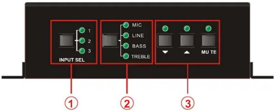
Figure 1 Front Panel
| No. | Name Function | |
| 1 | Audio Input Selection | To select the input audio source, after choosing the audio source, the corresponding LED indicator will be on. No.1 is for dual mono audio input (2 RCA connectors for L&R), No.2 is for stereo audio input (3.5mm mini jack), and No.3 is for digital fiber audio input. |
| 2 | Audio Control | Adjust the volume of the MIC, Line, or the level of Bass and Treble with this button |
| 3 | Volume Adjustment | To turn up/down or mute the corresponding audio. : Turn down the volume : Turn up the volumeMUTE: Mute the output |
2.2 Rear Panel
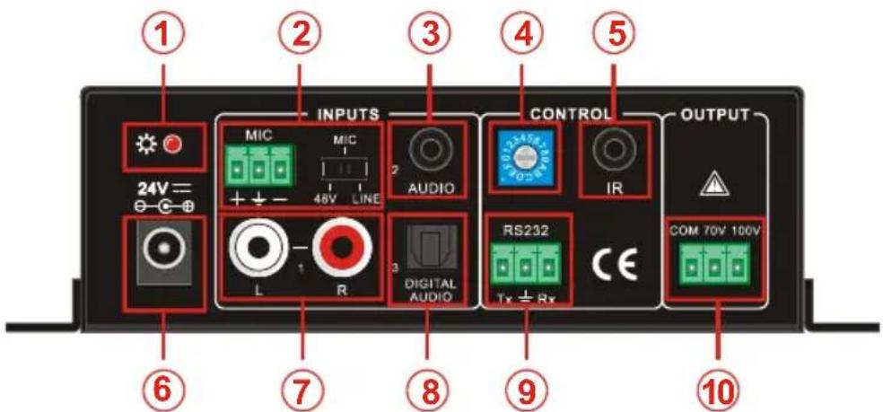
Figure 2 Rear Panel
| No. | Name Function | |
| 1 | Power Indicator | Turns red when power on. |
| 2 | Microphone input port | 3-pole captive screw connector for microphone input, the dial switch in right side is to select the micro input kind, including 48V (for condenser microphone), MIC (for dynamic microphone) and LINE (for line audio). |
| 3 | Audio Inputs | 3.5mm mini jack for stereo audio input, it can be connected to audio source device such as DVD player. |
| 4 | ID Code | 16 codes range from 0 to F (hexadecimal), works together with the PC control software. |
| 5 | IR | To connect with the IR receiver, works together with the IR remote. |
| 6 | Power Port | To connect with the power adapter (DC24V). |
| 7 | 2 x RCA | Dual-mono audio input, which can be connected with audio source device such as a PC. |
| 8 | Digital Audio Input | Fiber connector for digital audio input (PCM format only), it can be connected with a device with fiber port, such as blue-ray player. |
| 9 | RS232 | 3-pole captive screw connector for serial control, it can be connected with PC (Use a 3-pole captive to 9 pin female D connector and serial control software) to control PA100V. |
| 10 | Audio Output | To connect with audio output devices, such as speakers (To select 70V or 100V depends on the input voltage of the speakers). COM is for grounding (GND). |
3. System Connection
3.1 Usage Precautions
1) Do not use this without having load (speakers) connected.
2) Speakers must be connected before power on.
3.2 System Diagram
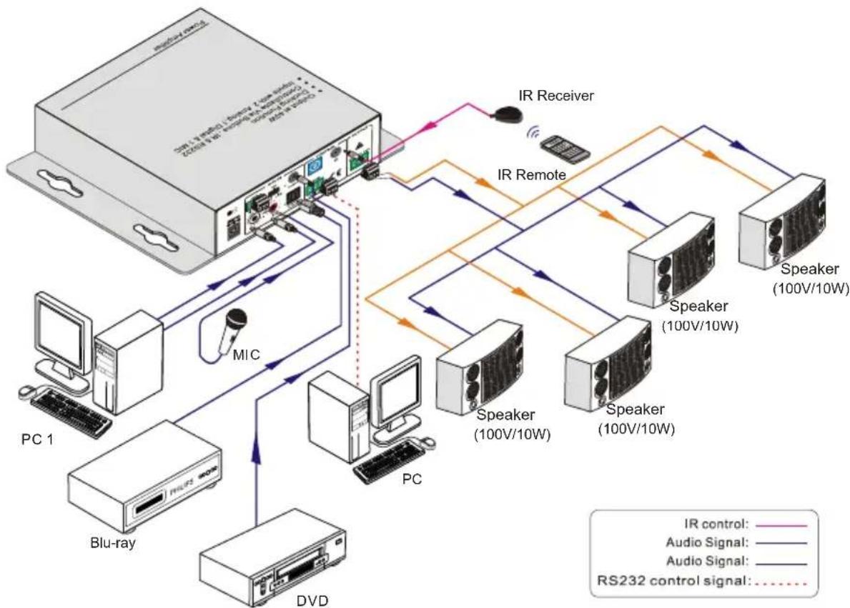
flowchart
graph TD
    A["PC 1"] -->|MIC| B["Blu-ray"]
    B --> C["PC"]
    C --> D["DVD"]
    D --> E["Speaker (100V/10W)"]
    E --> F["Speaker (100V/10W)"]
    F --> G["Speaker (100V/10W)"]
    G --> H["Speaker (100V/10W)"]
    H --> I["IR Receiver"]
    I --> J["IR Remote"]
    J --> K["Audio Signal: RS232 control signal"]
    style A fill:#f9f,stroke:#333
    style B fill:#ccf,stroke:#333
    style C fill:#cfc,stroke:#333
    style D fill:#fcc,stroke:#333
    style E fill:#cff,stroke:#333
    style F fill:#ffc,stroke:#333
    style G fill:#ffc,stroke:#333
    style H fill:#ffc,stroke:#333
    style I fill:#fff,stroke:#333
    style J fill:#fff,stroke:#333
    style K fill:#fff,stroke:#333
Figure 3 System Diagram
3.3 Audio Signal Connection
3.3.1 Audio Output
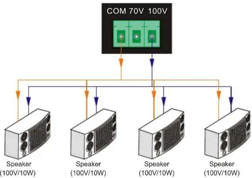
PA100V supports mono audio output, and the output voltage is 70V or 100V. The end COM is for grounding. The amplifier to be connected is mono audio output with a rated power at 40Watt, so PA100V can be connected with several speakers in parallel connection (Total power mustn't be more than 40Watt).
The following figure shows us how to connect the speakers. Here we take the 100V/10W speakers as an example.
flowchart
graph TD
    A["COM 70V 100V"] --> B["Speaker (100V/10W)"]
    A --> C["Speaker (100V/10W)"]
    A --> D["Speaker (100V/10W)"]
    A --> E["Speaker (100V/10W)"]
    A --> F["Speaker (100V/10W)"]
Figure 4 Audio Output Connection
Note: Speakers to be connected should be with constant pressure.
3.3.2 Audio Inputs
PA100V provides with 2 stereo audio inputs, one microphone input and one digital fiber audio input. The following figure shows the audio input ports.
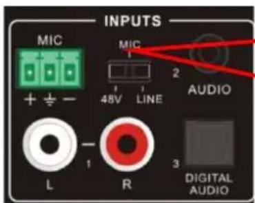
Dial Switch, to select the MIC input mode, includes MIC (dynamic microphone), 48V (condenser microphone) and LINE (normal audio or wireless microphone).
Figure 5 Audio Input Ports
48V phantom power input
When the switch turns to "48V" (It has a good frequency characteristic, high input impedance and high sensitivity in this mode), the MIC input will provide a 48V phantom power. This is usually used for power supply for condenser microphone, Connection is: "+" connects to positive, "-" connects to negative and "-" to ground.
Note: In this mode, only condenser microphone can be connected.
> MIC input
When the switch turns to "MIC" (It has a low frequency characteristics, and wide frequency response in this mode), the microphone input is used for connecting with dynamic microphone. There are two different connections:
a) Unbalanced connection:
“+” and “-” connect to ground, and “-” connects to signal.
“-” and “=” connect to ground, and “+” connects to signal.
b) Balanced connection: “+” connects to positive, “-” connects to negative and “≡” connects to ground.
LINE input
When the switch turns to "LINE" (It has a low frequency characteristics, and wide frequency response in this mode), the microphone input is used for connecting with normal audio or wireless microphone output. There are two different connections:
a) Unbalanced connection:
“+” and “-” connect to ground, and “-” connects to signal.
“-” and “” connect to ground, and “+” connects to signal.
b) Balanced connection: “+” connects to positive, “-” connects to negative and “≡” connects to ground.
- Digital Audio Input
PA100V has a fiber optical port to connect with digital audio source device. With the SPF optical fiber, the audio signal can be transmitted faster, more stable, reliable, and can be transmitted over a long distance without distortion.
Notice: This digital audio input can support/decode PCM format signal only. If the CD/DVD is DTS or AC3 format, please set the player to PCM format output before connecting to PA100V.
3.4 System Applications
PA100V can be applied in different occasions, such as classroom, small meeting room, lecture hall, bar and hotel etc.
4. System Operations
4.1 Operations of Front Panel
The buttons provides the control of volume/EQ control and switching. The LED indicator will show the connecting status. The following content introduces audio switching and EQ control in detail.
Operations: Press the corresponding button again for cyclic switching.
4.1.1 Audio switching
There are three switchable audio inputs, one 2xRCA input, one 3.5mm jack input, and one digital fiber audio input, switchable through the buttons as below:
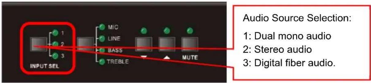
flowchart
graph LR
    A["INPUT SEL"] --> B["MIC"]
    A --> C["LINE"]
    A --> D["BASS"]
    A --> E["TREBLE"]
    B --> F["Output"]
    C --> G["Output"]
    D --> H["Output"]
    E --> I["Output"]
    J["Audio Source Selection"] --> K["1: Dual mono audio"]
    J --> L["2: Stereo audio"]
    J --> M["3: Digital fiber audio"]
Figure 6 Audio Source Selection Button
4.1.2 Volume/EQ controlling
The line volume and MIC volume can be controlled by the buttons.
The MIC Volume/LINE volume/LINE bass/LINE treble will be selected by the buttons, and controlled up/down/mute by the function buttons. Please check the picture below:
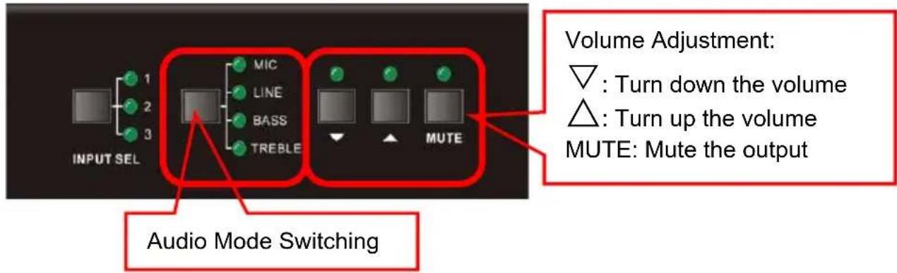
Figure 7 Audio Mode and Volume Adjustment buttons
For example, to turn up the line volume, you should select the "LINE" first, and then press the button "▲
4.2 Operations of IR Remote
PA100V provides with an IR eye, with the IR Receiver and the IR remote, user can control PA100V remotely.
Notice: The IR Receiver and the IR remote are all offered for charge.
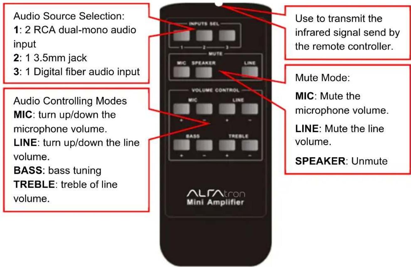
Figure 8 IR Remote
IR receiver, works together with the IR remote. Please point the IR remote at the IR receiver when use, to avoid getting out of control as there is no signal detected.
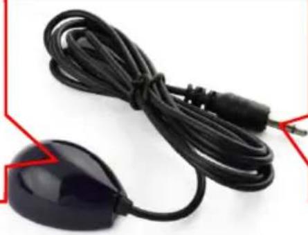
natural_image
Close-up of a black cordless cable with a small electronic device attached (no visible text or symbols)3.5mm jack Insert it into the specialized PA3 socket (3.5mm), to connect the IR receiver with PA3.
Figure 9 IR Receiver
4.3 Operations of Control Software
4.3.1 Connection with Computer
When the amplifier connects to the COM1 or COM2 of the computer with control software, users can control it by that computer.
To control the amplifier, users should use a 3-pole male captive screw to 9-pin HD female connector and use the public COM software.
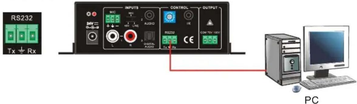
Figure 10 Connection of RS232 Port
4.3.2 Installation/uninstallation of RS232 Control Software
- Installation
Connect the input source devices and the output device according to the system diagram.
➢ Copy the RS232 control software to one computer, and then connect the RS232 port of this computer and PA100V.
Double-click the EXE program to execute the software.
Here we take the software CommWatch.exe as example. The icon is showed as below:

CommWatch.exe
Figure 11 Control Software
- Uninstallation Delete all the control software files in corresponding file path.
4.3.3 Running Environment
While the control software is installed, we can activate the software through the RS232 port and set the parameters, to make it able to send RS232 commands to control PA100V.
4.3.4 Function Settings
With the control software, we can easily switch the input channel, mute the output, check the working status, and adjust the volume etc. Please refer the details in RS232 Communication Commands.
The interface of the control software is showed as below:
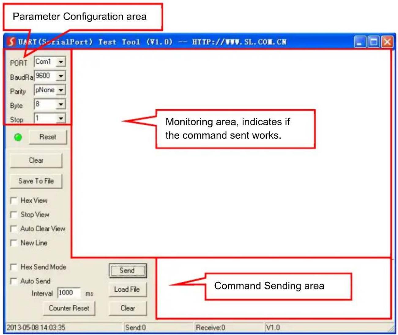
Figure 12 Main Interface of Control Software
4.3.5 RS232 Communication Commands
Communication Protocol: RS232 Communication Protocol
Baud rate: 9600
Data bit: 8
Stop bit: 1
Parity bit: none
| Command Function Description Feedback Code | ||
| 1A1. Switching the audio to input 1 A: 1 -> 1 | ||
| 2A1. Switching the audio to input 2 A: 2 -> 1 | ||
| 3A1. Switching the audio to input 3 A: 3 -> 1 | ||
| 0A0. Mute Audio of MIC and Line out Mute | ||
| 1A0. Mute audio of MIC Mute MIC | ||
| 2A0. Mute audio of line out Mute LIN | ||
| 3A0. Enable noise gate. Gate On | ||
| 4A0. Disable noise gate. Gate Off | ||
| 0A1. Unmute Audio Unmute Audio | ||
| 600% Checking the working status | A: 1 -> 1Volume of MIC : 50Volume of LINE : 50Bass of LINE : 4Treble of LINE : 4Ducking Off | |
| 601% MIC volume up | Volume of MIC: 51 | |
| 602% MIC volume down | Volume of MIC: 51 | |
| 603% Line volume up | Volume of LINE: 51 | |
| 604% Line volume down | Volume of LINE: 51 | |
| 605% Bass level up | Bass of LINE: 4 | |
| 606% Bass level down | Bass of LINE: 4 | |
| 607% Treble level up | Treble of LINE: 4 | |
| 608% Treble level down | Treble of LINE: 4 | |
| 609% Initialization, back to the default setting | Init OK | |
| 610% Enable/disable the ducking function. | Ducking off/Ducking on | |
| 4[x][x]% | Preset the volume level of ducking function. [xx] Arranges from [00] to [60]. 61 degrees in total. | Ducking of LINE: 50 |
| 5[x][x]% | Preset MIC volume, [xx] arranges from [00] to [60]. 61 degrees in total. | Volume of MIC: 50 |
| 7[x][x]% | Preset line volume, [xx] arranges from [00] to [60]. 61 degrees in total. | Volume of LINE: 50 |
| 8[x][x]% | Preset the bass level, [xx] arranges from [00] to [08]. 9 degrees in total. | Bass of LINE: 4 |
| 9[x][x]% | Preset the treble level, [xx] arranges from [00] to [08]. 9 degrees in total. | Treble of LINE: 4 |
Notice:
-
The letter inside bracket [] is the variable code, which is changeable.
-
The bracket [] is not included to the RS232 commands.
-
Any dot “.” after the letters is part of the commands.
4. Ducking function:
When input with MIC, the volume of the line audio will be automatically turned down to the preset volume level, if there is no input MIC audio signal after 5 seconds, then the volume will be automatically turned up to the original one. If you need to disable/enable the ducking function, just send the command "610%" again.
5. ID coding
The ID codes of PA100V ranges from 0 to F (hexadecimal), when sending RS232 commands, please take notice of the address of the ID code.
If the address of the ID code is 0, any RS232 command is available.
If the address is in 1\~F, it has one unique ID code (If the ID code is not the same with the address, no RS232 command will work).
While the ID code is in 1\~F, please add "ID/" before sending the command.
For example, if the ID code is 5, the RS232 command needed is "604%", the correct command is in this format: 5/604%.
There is no need to add "ID/" before the command when the ID code is 0.
Examples:
1) Switching the input 2 to the line out, the command is: 2A1.
2) Turning up the volume of line audio, the command is: 603%
3) Preset the MIC volume to "21" degree, the command is: 521%
4) Checking the working status of PA100V, the command is: 600%
5) If the ID code is 0, sending command 601% is able to turn up the MIC volume. If the ID code is 2, sending command 601% will not work, and the MIC volume remains unchanged. The right command is 2/601%.
- Specifications
| Audio Input Audio Output | |||
| Input | 2 stereo audio1 MIC1 Digital fiber audio | Output 1 mono amplifier | |
| Input Connector | 2 RCA1 3.5mm jack1 3-pole 3.81mmcaptive screw connector1 SPF fiber connector | Output Connector | 1 3-pole 3.81mm captive screw connector |
| Input Impedance | >10KΩ Output Type | Constant voltage 70V or 100V. | |
| Audio General | |||
| Frequency Response | 120Hz ~ 20KHz CMRR | >70dB@20Hz~20KHz | |
| SNR 80dB (Max) | Bandwidth 120Hz ~ 20KHz | ||
| Rated Power Output | 40Watt THD + Noise | 1%@1KHz,0.3%@20KHz at nominal level | |
| Voltage Gain 26dB | |||
| Control Function | |||
| RS232 Control | 1 3-pole 3.81mmcaptive screw connector | Front Panel Control | buttons |
| ID Code Control | 16 ID codes for control. | ||
| Optional | IR remote & TCP/IP controlled by PTNET(PTN's programmable interface) | ||
| General | |||
| Temperature -10 | ~ +40°C Humidity 10% ~ 90% | ||
| Power Supply | DC 24V power adapter | Standby Power Consumption | 5W |
| Case Dimension | W130 x H44 x D144mm (1U high) | Product Weight | 0.86Kg |
6. Panel Drawing
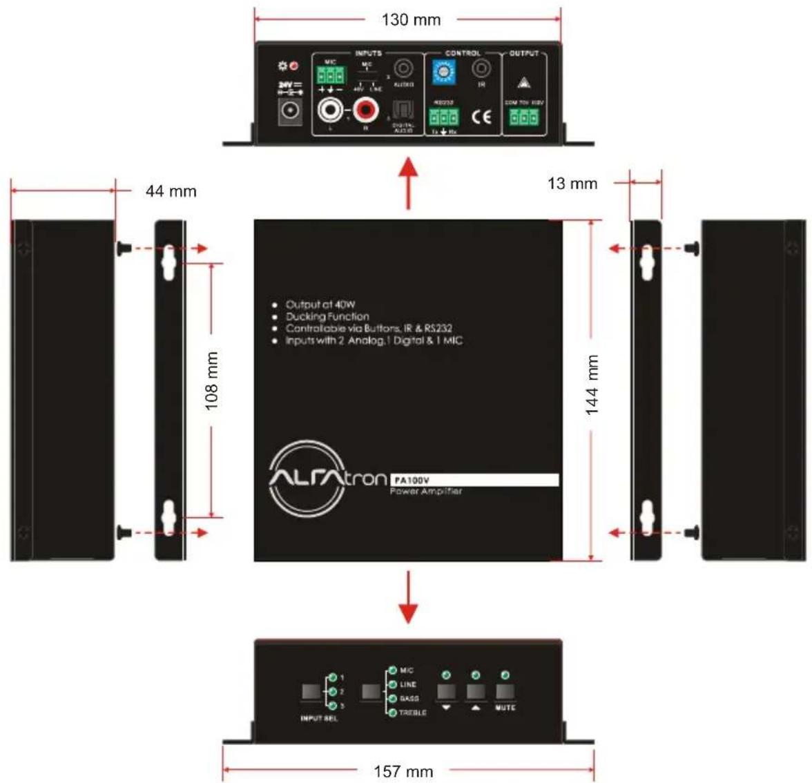
Figure 13 Panel Drawing
7. Troubleshooting and Maintenance
| Problems Causes Solutions | ||
| No output audio | No signal at input/ output end | Check input/ output signal by an oscilloscope or a multi-meter. |
| Failed cable connection Change for another cable. | ||
| Broken unit | Send it to the dealer for repair. | |
| POWER indicator doesn’t work or no response from unit. | Failed power connection | Make sure the power cord connection is good |
| Static becomes stronger when connecting the video connectors | Bad grounding | Check the grounding and make sure it is connected well. |
| Interference on audio output | ||
| Cannot control the device by front panel buttons, RS232 port or IR remote | Broken unit | Send it to the dealer for repair |
If your problem persists after following the above troubleshooting steps, seek further help from authorized dealer or our technical support.
8. Warranty
1. Limited warranty in respect of Alfatron Products Only
1.1 This limited warranty covers defects in materials and workmanship in this product.
1.2 Should warranty service be required, proof of purchase must be presented to the Company. The serial number on the product must be clearly visible and not have been tampered with in any way whatsoever.
1.3 This limited warranty does not cover any damage, deterioration or malfunction resulting from any alteration, modification, improper or unreasonable use or maintenance, misuse, abuse, accident, neglect, exposure to excess moisture, fire, improper packing and shipping (such claims must be presented to the carrier), lightning, power surges, or other acts of nature. This limited warranty does not cover any damage, deterioration or malfunction resulting from the installation or removal of this product from any installation, any unauthorized tampering with this product, any repairs attempted by anyone unauthorized by the Company to make such repairs, or any other cause which does not relate directly to a defect in materials and/or workmanship of this product. This limited warranty does not cover equipment enclosures, cables or accessories used in conjunction with this product.
This limited warranty does not cover the cost of normal maintenance. Failure of the product due to insufficient or improper maintenance is not covered.
1.4 The Company does not warrant that the product covered hereby, including, without limitation, the technology and/or integrated circuit(s) included in the product, will not become obsolete or that such items are or will remain compatible with any other product or technology with which the product may be used.
1.5 Only the original purchaser of this product is covered under this limited warranty. This limited warranty is not transferable to subsequent purchasers or owners of this product.
1.6 Unless otherwise specified, the goods are warranted in accordance with the manufacturer's product specific warranties against any defect attributable to faulty workmanship or materials, fair wear and tear being excluded.
1.7 This limited warranty only covers the cost of faulty goods and does not include the cost of labor and travel to return the goods to the Company's premises.
1.8 In the event of any improper maintenance, repair or service being carried out by any third persons during the warranty period without the Company's written authorization, the limited warranty shall be void.
1.9 A 7 (seven) year limited warranty is given on the aforesaid product where used correctly according to the Company's instructions, and only with the use of the Company's components.
1.10 The Company will, at its sole option, provide one of the following three remedies to whatever extent it shall deem necessary to satisfy a proper claim under this limited warranty:
1.10.1 Elect to repair or facilitate the repair of any defective parts within a reasonable period of time, free of any charge for the necessary parts and labor to complete the repair and restore this product to its proper operating condition.; or
1.10.2 Replace this product with a direct replacement or with a similar product deemed by the Company to perform substantially the same function as the original product; or
1.10.3 Issue a refund of the original purchase price less depreciation to be determined based on the age of the product at the time remedy is sought under this limited warranty.
1.11 The Company is not obligated to provide the Customer with a substitute unit during the limited warranty period or at any time thereafter.
1.12 If this product is returned to the Company this product must be insured during shipment, with the insurance and shipping charges prepaid by the Customer. If this product is returned uninsured, the Customer assumes all risks of loss or damage during shipment. The Company will not be responsible for any costs related to the removal or re-installation of this product from or into any installation. The Company will not be responsible for any costs related to any setting up this product, any adjustment of user controls or any programming required for a specific installation of this product.
1.13 Please be aware that the Company's products and components have not been tested with competitor's products and therefore the Company cannot warrant products and/or components used in conjunction with competitor's products.
1.14 The appropriateness of the goods for the purpose intended is only warranted to the extent that the goods are used in accordance with the Company's installation, classification and usage instructions.
1.15 Any claim by the Customer which is based on any defect in the quality or condition of the goods or their failure to correspond with specification shall be notified in writing to the Company within 7 days of deliver or (where the defect or failure was not apparent on reasonable inspection by the Customer) within a reasonable time after discovery of the defect or failure, but, in any event, within 6 months of delivery.
1.16 If delivery is not refused, and the Customer does not notify the Company accordingly, the Customer may not reject the goods and the Company shall have no liability and the Customer shall pay the price as if the goods had been delivered in accordance with the Agreement.
1.17 THE MAXIMUM LIABILITY OF THE COMPANY UNDER THIS LIMITED WARRANTY SHALL NOT EXCEED THE ACTUAL PURCHASE PRICE PAID FOR THE PRODUCT.
- Safety Operation Guide
- Table of Contents
- Introduction....1
- Panel Description....2
- System Connection....4
- System Operations ....6
- Specifications....13
- Introduction
- Introduction to PA100V
- Features
- Package Contents
- Panel Description
- Front Panel
- Rear Panel
- System Connection
- Usage Precautions
- System Diagram
- Audio Signal Connection
- Audio Output
- Audio Inputs
- 48V phantom power input
- > MIC input
- LINE input
- - Digital Audio Input
- System Applications
- System Operations
- Operations of Front Panel
- Audio switching
- Volume/EQ controlling
- Operations of IR Remote
- Operations of Control Software
- Connection with Computer
- Installation/uninstallation of RS232 Control Software
- - Installation
- Running Environment
- Function Settings
- RS232 Communication Commands
- Notice:
- Ducking function:
- ID coding
- Examples:
- Panel Drawing
- Troubleshooting and Maintenance
- Warranty
- Limited warranty in respect of Alfatron Products Only
Brand : Alfatron
Model : ALF-PA100V
Category : Blender