7FS100A-IW-NF-ST-00 - Ice machine Follett - Free user manual and instructions
Find the device manual for free 7FS100A-IW-NF-ST-00 Follett in PDF.

| Product Type | Ice Machine |
| Brand | Follett |
| Model | 7FS100A-IW-NF-ST-00 |
| Ice Production Capacity | Up to 1,000 lbs per day |
| Ice Type | Chewable nugget ice |
| Storage Capacity | Approximately 180 lbs |
| Dimensions (W x D x H) | 30 x 30 x 72 inches |
| Weight | Approximately 350 lbs |
| Power Supply | 115V / 60Hz / 1-Phase |
| Amperage | 15 A |
| Condenser Type | Air-cooled |
| Refrigerant | R-404A |
| Installation Type | Freestanding or undercounter |
| Water Connection | 3/8 inch female flare fitting |
| Drain Connection | 3/4 inch female NPT |
| Cleaning Cycle | Automatic cleaning cycle with Follett cleaner |
| Filter | Optional external water filter required |
| Certifications | NSF, UL |
| Warranty | 3 years parts and labor, 5 years compressor |
Frequently Asked Questions - 7FS100A-IW-NF-ST-00 Follett
User questions about 7FS100A-IW-NF-ST-00 Follett
0 question about this device. Answer the ones you know or ask your own.
Ask a new question about this device
Download the instructions for your Ice machine in PDF format for free! Find your manual 7FS100A-IW-NF-ST-00 - Follett and take your electronic device back in hand. On this page are published all the documents necessary for the use of your device. 7FS100A-IW-NF-ST-00 by Follett.
USER MANUAL 7FS100A-IW-NF-ST-00 Follett
Installation, Operation and Service Manual Serial numbers above D25455
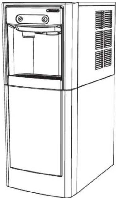
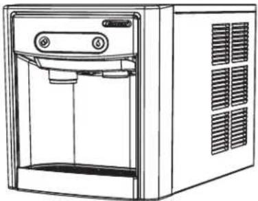
7FS100A
natural_image
Line drawing of a modern water dispenser with front panel and side vent (no text or symbols)7CI100A
natural_image
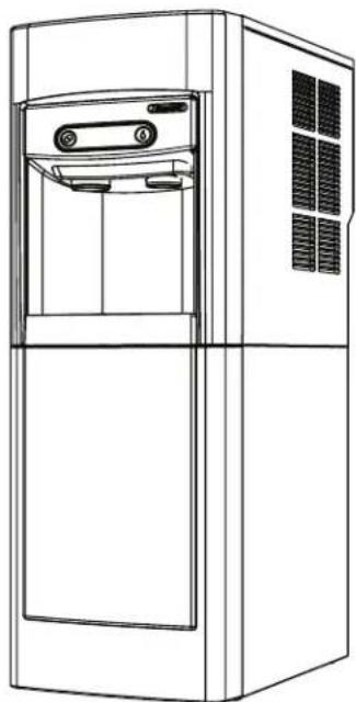
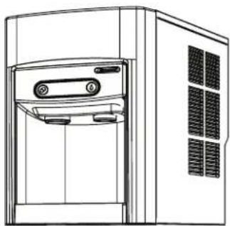
Line drawing of a modern water dispenser with control panel and ventilation slots (no text or symbols)15FS100A
natural_image
Line drawing of a modern stainless steel refrigerator with front panel and side door (no text or symbols)15CI100A
natural_image
Line drawing of a front view of a server unit with ventilation grilles and control panel (no text or symbols)Following installation, please forward this manual to the appropriate operations person.
Contents
Welcome....3
Before You Begin.... 3
Important Safety Information.... 4
Specifications 4
Dimensions 4
Ambient Information 4
Plumbing....4
Specifications 5
Water 5
Clearances 5
Electrical 5
Refrigeration 5
Heat Rejection 5
7 Series Detailed Drawing 6
15 Series Detailed Drawing 7
Installation 8
Countertop Installation 8
Freestanding Installation....9
Maintenance/Cleaning Mode 12
Accessing Internal Components.... 12
Filter Display Indicator Activation.... 13
NSF-approved Cleaning and Sanitizing Procedure.... 14
Service 15
LED Indicator Description.... 15
Evaporator Disassembly.... 16
Evaporator Assembly 19
Water Feed Schematic 23
Bin Melt Water/Evaporator Feed/Clean Out System Schematic 24
Vent System Schematic 24
Refrigeration Schematic 25
Condenser Fan Motor Removal (7 Series Shown) 26
User Interface Display Identification....27
Electrical Wiring Diagram....29
Parts 30
7 Series Exterior....30
7 Series Interior 32
Parts 34
15 Series Exterior 34
15 Series Interior 36
7 Series Bin Assembly 38
15 Series Bin Assembly 40
Evaporator Assembly 42
Base Stand 44
Welcome
Follett equipment enjoys a well-deserved reputation for excellent performance, long-term reliability, and outstanding after-the-sale support. To ensure that this product delivers that same degree of service, we ask that you take a moment to review this manual before beginning the installation. Should you have any questions or require technical help at any point, please call our technical service group at (877) 612-5086 or +1 (610) 252-7301.
Before You Begin
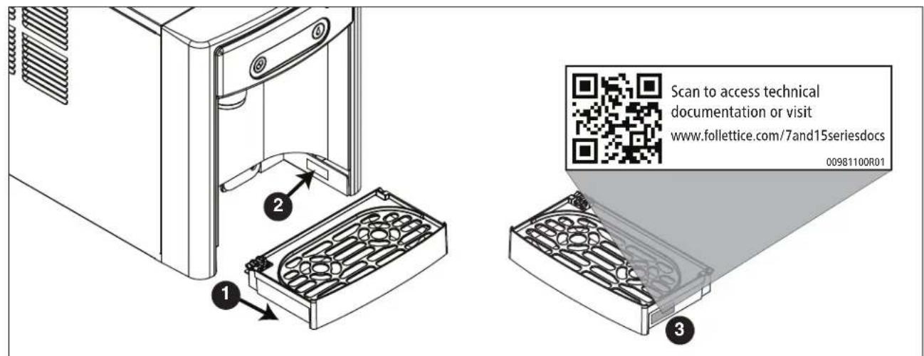
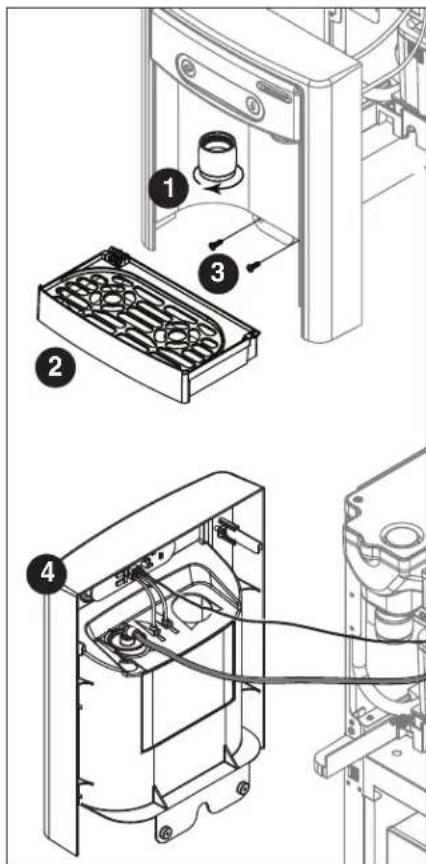
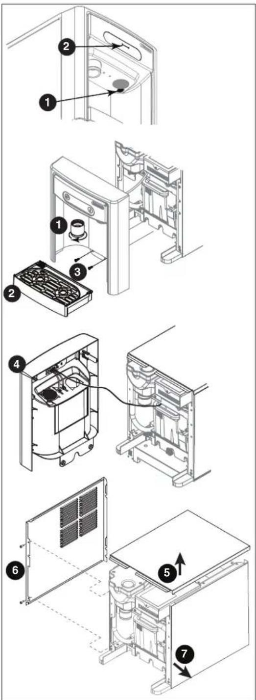
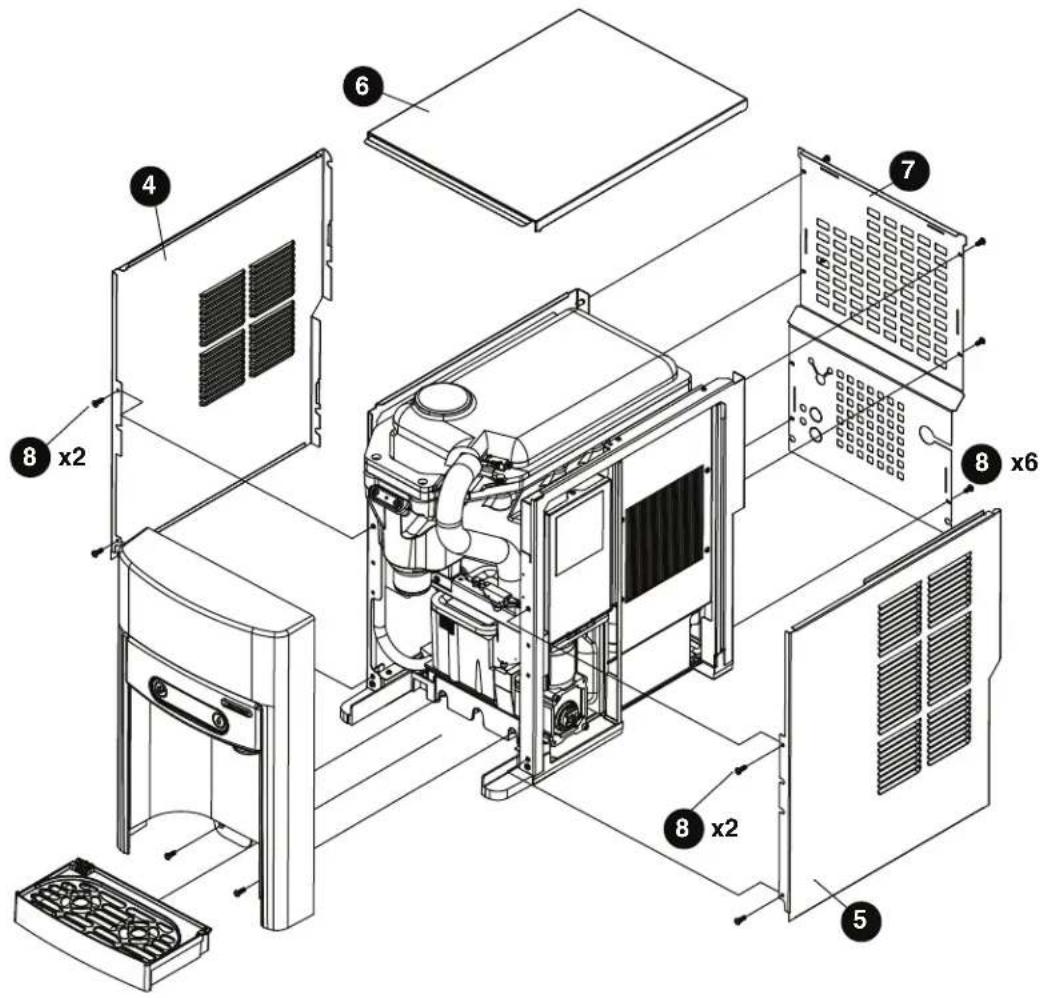
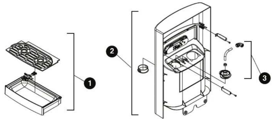
After uncrating and removing all packing material, inspect the equipment for concealed shipping damage. If damage is found, immediately notify the shipper and contact Follett Corporation so that we can help in the filing of a claim, if necessary. If needed, the serial number of your dispenser can be found by removing the drip tray ① and locating the serial number label ②. A QR Code is located on the right hand side of the drip tray ③. This code allows you to access manuals, technical bulletins, and on-line training related to the 7 Series and 15 Series dispensers.
Check your paperwork to verify that you received the correct dispenser. Follett configuration numbers are designed to provide information about the type of dispenser you are receiving. The following is an explanation of the different model numbers.
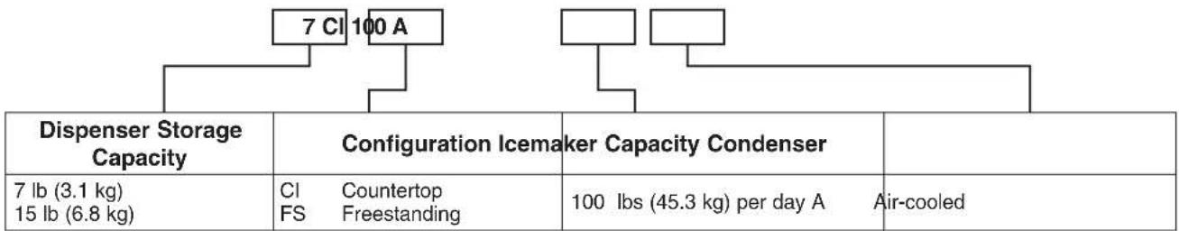
flowchart
graph TD
    A["7 Cl 100 A"] --> B["Configuration Icemaker Capacity Condenser"]
    B --> C["Air-cooled"]
    D["Dispenser Storage Capacity"] --> E["Configuration Icemaker Capacity Condenser"]
    E --> F["Configuration Icemaker Capacity Condenser"]
    G["7 lb (3.1 kg) 15 lb (6.8 kg)"] --> H["Configuration Icemaker Capacity Condenser"]
    H --> I["Configuration Icemaker Capacity Condenser"]
    J["Countertop FS Freestanding"] --> K["Configuration Icemaker Capacity Condenser"]
    K --> L["Configuration Icemaker Capacity Condenser"]
    M["Ibs (45.3 kg) per day A"] --> N["Air-cooled"]
Important Safety Information
Please read and adhere to the following safety information while installing, using, or servicing your Follett Ice Dispenser.
- Always disconnect power before servicing the dispenser.
- Ice is slippery. Maintain counters and floors around dispenser in a clean and ice-free condition.
- Ice is food. Follow the recommended cleaning and sanitizing instructions to maintain cleanliness of delivered ice.
Specifications
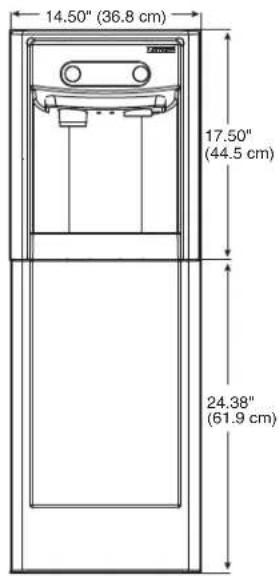
Dimensions
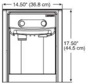
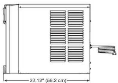
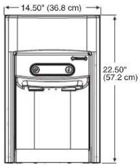
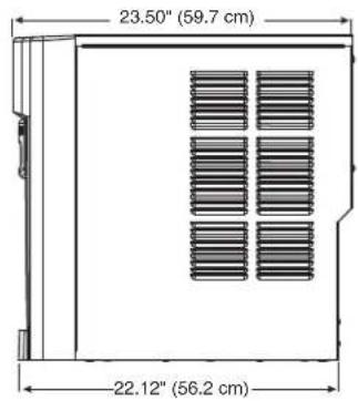
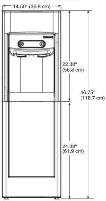
| 7CI100A 7FS100A 15CI100A 15FS100A | |||
| Width 14.50" (40 cm) 14.50" (36.8 cm) 14.50" (40 cm) 14.50" (40 cm) | |||
| Depth | 22.12" (56.2 cm) | 22.12" (56.2 cm) | 23.50" (59.7 cm) |
| Height | 17.50" (44.5 cm) | 41.88" (106.4 cm) | 22.50" (57.2 cm) |
| Unit Shipping Weight | 90 lb (41 kg) | 120 lb (54.4 kg) | 100 lb (45.4 kg) |
Ambient Information

CAUTION!
The 7CI100A/7FS100A and 15CI100A/15FS100A are for indoor use only. Designed for commercial use. Follett is not able to provide in-house services for residential installations.
| Maximum* | Minimum* | |
| Air Temperature ^ | 100 F (38 C) | 50 F (10 C) |
| Water Temperature | 90 F (32.2 C) | 40 F (4.5 C) |
| Water Pressure 70 psi (483 kpa) | 10 psi (69 kpa) | |
| Relative Humidity | 55% at 78 F (25.5 C) | |
| * Use outside of these limitations is misuse and will void warranty. Best performance is achieved between 80 F (27 C) and 50 F (10 C). | ||
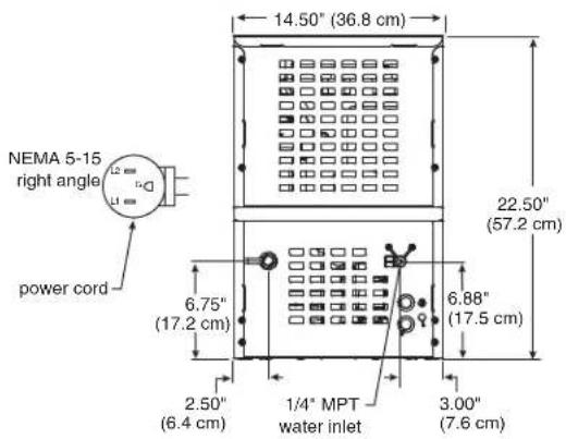
Plumbing
■ Water Inlet: 1/4" MPT
- Optional Drain Accessory Kit (item# 00956375 or 00981977): 1/2" ID tubing
■ Water shut-off recommended within 5 ft. (1.5 m) of dispenser
Specifications
Water

WARNING!
Connect to potable water supply only.
■ Water Mineral Content:
– TDS: greater than 5 ppm (mg/l) but less than 400 ppm (mg/l)
– Hardness: Less than 200 mg/l (12 gpg)
■ Not recommended for use with softened water
Clearances
- 3" (77 mm) behind and on each side of dispenser for electrical and connection and ventilation
Electrical
■ 115V, 60 Hz, 1 phase, 5A, maximum fuse 15A
- Connect to dedicated 15A circuit, fuse or breaker
- Must be grounded - requires 3-prong outlet. Do not remove ground.
Refrigeration

WARNING!
Do not damage the refrigerant circuit. Refrigerant can cause personal injury and/or damage dispenser.
- Refrigerant R134a – 7.2 ounces (204 grams)
Heat Rejection
■ 1700 BTU/hr (498 W)
Specifications (continued)
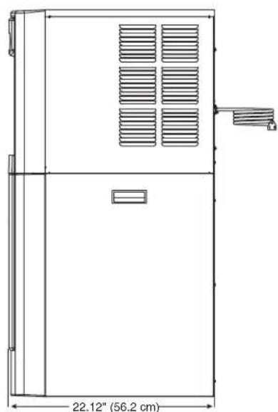
7 Series Detailed Drawing
Countertop models
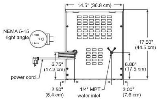
Freestanding models
natural_image
Technical line drawing of a rectangular industrial or storage unit with ventilation grilles and a 22.12" dimension label (no text or symbols beyond the dimension)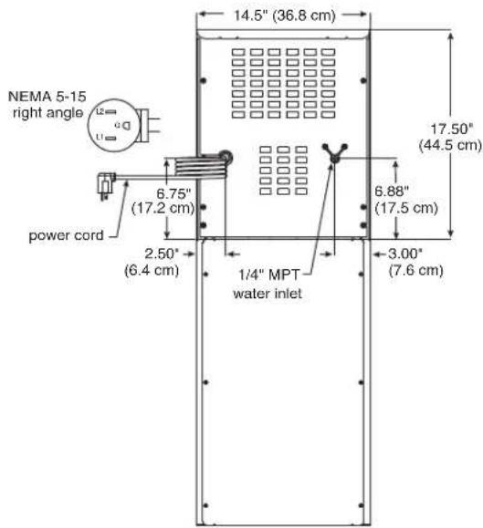
Specifications (continued)
15 Series Detailed Drawing
Countertop models
Freestanding models

CAUTION!
No service or maintenance should be performed until the technician has thoroughly read this service manual. Except for routine cleaning and sanitizing, only qualified technicians should attempt to service or maintain this equipment.
Countertop Installation
The 7 Series countertop model is designed to fit on counters underneath standard mounted cabinets, this does not apply to 15 Series models. See page 4 for dimensions. Installation instructions for freestanding model may be found on page 9.
- A clearance of at least 3" (77 mm) is required behind and on each side of the dispenser for electrical connection and ventilation (Fig. 1).
-
Rough-in the electrical service and water line.
-
Electrical: 115V, single phase, 15A receptacle required. The dispenser has an integral 8 ft. (2.4 m) cord and plug.
- Water: supply line (with shut-off valve) connects to the dispenser's 1/4" MPT inlet.
NOTICE!
If installing optional Drip Tray Drain Kit or Leg Accessory, complete those steps before proceeding. Refer to instructions included with the Drip Tray Drain Kit, or see page 9 for Leg Accessory instructions.
- Connect water line. Recommended routing (Fig. 2) allows easy access to water for cleaning and sanitizing procedure.
- If installing the optional internal water filter*, please see Maintenance/Cleaning Mode on page 12 before proceeding. If not, proceed to step 5.
* If your dispenser has the internal water filter option, the water filter must be installed for the dispenser to operate. Because internal components will need to be accessed for both procedures, Follett recommends installing the water filter just prior to initial sanitizing.
- Connect power supply.
- Sanitize the dispenser prior to use (see the Initial Sanitizing Kit instructions shipped with this unit).
Fig. 1
Fig. 2
Optional Leg Accessory Installation

CAUTION!
Use caution when tipping the dispenser during leg installation. Do not lay unit on back or side. DO NOT EXCEED 30° angle. Tipping more than 30° can result in compressor malfunction.
- If installing optional 4" Leg Accessory (item# 00956300), place a 5" (127 mm) spacer underneath the dispenser to ease installation.
- Remove four plastic, thread-protecting plugs from bottom of dispenser.
- Screw each leg into chassis (Fig. 3).
Fig. 3
Freestanding Installation
Installation instructions for countertop model may be found on Countertop Installation on page 8.
- A clearance of at least 3" (77 mm) is required behind and on each side of the dispenser for electrical connection and ventilation (Fig. 4).
-
Rough-in the electrical service and water line.
-
Electrical: 115V, single phase, 15A receptacle required. The dispenser has an integral 8 ft. (2.4 m) cord and plug.
- Water: supply line (with shut-off valve) connects to the dispenser's 1/4" MPT inlet.
NOTICE!
If installing optional Leg Accessory, complete those steps before proceeding. See page 11 for Leg Accessory instructions.
Fig. 4
Installation (continued)
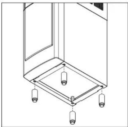
- Remove four plastic, thread-protecting plugs from bottom of dispenser.
- Attach dispenser to base stand with supplied hardware (Fig. 5).
NOTICE!
If installing optional Drip Tray Drain Kit, refer to instructions included with the Drip Tray Drain Kit.
Fig. 5
natural_image
Technical illustration of a kitchen appliance with a close-up view showing internal components (no text or symbols)- Connect water line. Recommended routing (Fig. 6) allows easy access to water for cleaning and sanitizing procedure.
- If installing the optional internal water filter*, please see Optional Internal Water Filter Installation on page 11 before proceeding. If not, proceed to step 7.
* If your dispenser has the internal water filter option, the water filter must be installed for the dispenser to operate. Because internal components will need to be accessed for both procedures, Follett recommends installing the water filter just prior to initial sanitizing.
- Connect power supply.
- Sanitize the dispenser prior to use (see the Initial Sanitizing Kit instructions shipped with this unit).
Fig. 6
Installation (continued)
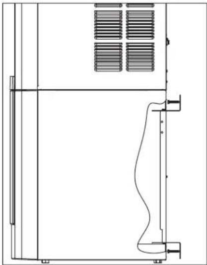
- Secure unit to wall or cove molding with supplied bracket (Fig. 7) to prevent tipping.
Note: Fasteners must be supplied by installer.

WARNING!
Freestanding unit must be secured to wall to prevent tipping. Failure to do could result in personal injury or damage to the unit.
Optional Leg Accessory Installation
- If installing optional 6" Leg Accessory (item# 00956318), tilt or lay base stand on side and screw each leg into stand (Fig. 8).
Fig. 7
natural_image
Technical line drawing of a mechanical or electrical enclosure with ventilation grilles and mounting feet (no text or symbols)Fig. 8
natural_image
Technical line drawing of a mechanical or architectural component with four cylindrical components and mounting holes (no text or symbols)Fig. 9
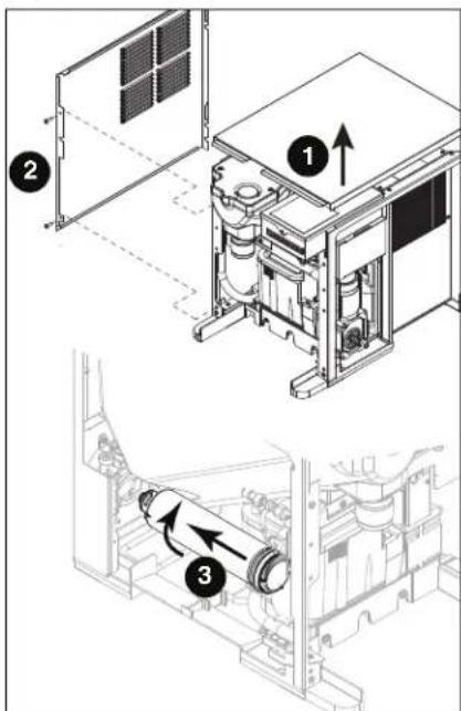
Optional Internal Water Filter Installation
If your dispenser has the internal water filter option, the water filter must be installed for the dispenser to operate. Because internal components will need to be accessed for both procedures, Follett recommends installing the water filter just prior to initial sanitizing.
- If installing the optional internal water filter, please complete the steps shown in Accessing Internal Components on page 12 before proceeding.
- Lift and remove the top panel, set aside (Fig. 9.1).
- Remove two screws (Fig. 9.2) and remove left side panel.
- Install filter as shown. Turn filter clockwise until it is fully seated (Fig. 9.3).
Maintenance/Cleaning Mode
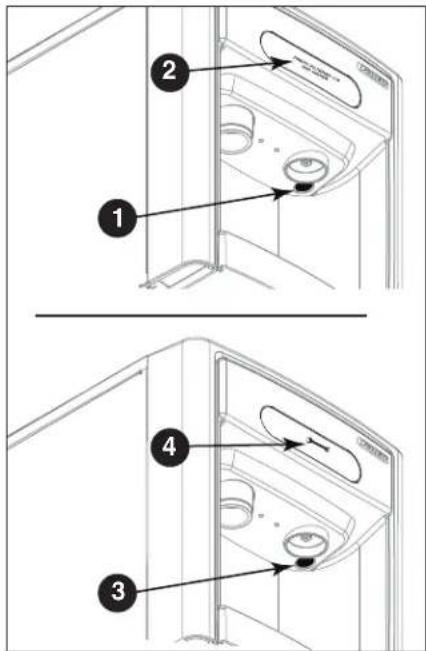
Cleaning Mode (Dispensing Disabled) - Use when cleaning surface
Entering Cleaning Mode disables the User Interface and allows you to clean the outside of the dispenser without accidentally dispensing water or ice.
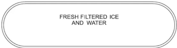
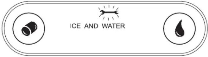
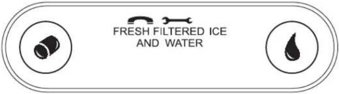
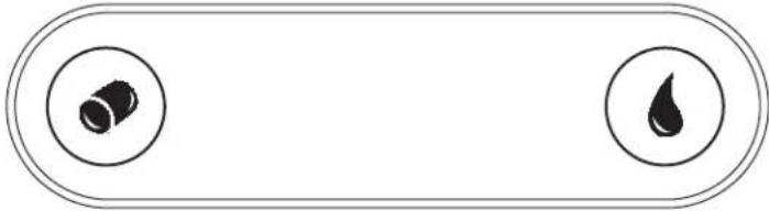
- To enter Cleaning Mode, press and immediately release the maintenance/clean switch (Fig. 10.1) so that only "FRESH FILTERED ICE AND WATER" displays in the user interface (Fig. 10.2).
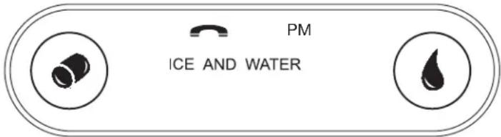
- To exit Cleaning Mode, press and immediately release the maintenance/clean switch so that the ice and water icons also display in the user interface.
Maintenance Mode (All Operations Disabled) - Use when cleaning ice machine
Entering Maintenance Mode disables all operations and allows you to safely clean and/or sanitize the icemaker and dispenser.
- To enter Maintenance Mode, press and hold the maintenance/clean switch (Fig. 10.3) until → displays in the user interface (Fig. 10.4).
- To exit Maintenance Mode, press and hold the maintenance/clean switch until no longer displays in the user interface.
Note: Entering and exiting Maintenance Mode will reset the six-month periodic maintenance reminder.
Fig. 10
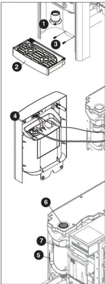
Accessing Internal Components

CAUTION!
Except for routine cleaning and sanitizing, only qualified technicians should attempt to service or maintain this equipment.
- Press and hold the maintenance/clean switch (Fig. 10.1) until displays in the user interface (Fig. 10.2).
- Remove (unscrew) chrome ice dispenser chute (Fig. 11.1).
- Remove the drip tray (Fig. 11.2).
- Remove the two screws (Fig. 11.3) on the front panel (behind the drip tray).
- Remove and set aside the front panel (Fig. 11.4) - do not disengage the plug on the back of the User Interface or the tubing at the water dispenser chute (if so equipped).
Fig. 11
Filter Display Indicator Activation
If you purchased your dispenser with a Follett filter, the filter display indicator activation has been preset at the factory.
If you are using an "after market filter," an adjustment may be made to activate the "Fresh Filtered Ice & Water" display.
Activating "Fresh Filtered Ice & Water"
- Remove the front panel as explained in Accessing Internal Components on page 12 then refer to Fig. 12.
- Remove top panel (Fig. 12.1). Note: For 15 Series dispensers, the right side panel must also be removed.
- Remove (1) screw and top of control board enclosure (Fig. 12.2).
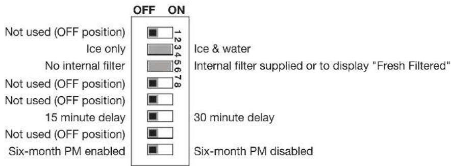
- Locate the DIP switches on the dispenser's control board (Fig. 13). Use a fine-pointed object to move the "Filter" DIP switch (DIP switch #3) to the ON position.
Deactivating the Six-Month Maintenance/Filter Change Reminder
- Use a fine-pointed object to move the "PM" DIP switch (DIP switch #8) to the ON position.
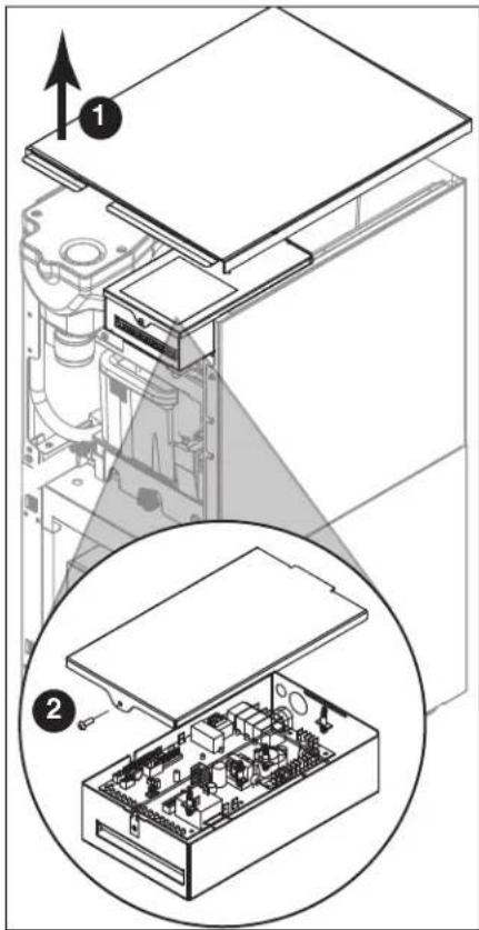
Fig. 13
bar
| Category | Value | |---|---| | Not used (OFF position) | 1234 | | Ice only | 5678 | | No internal filter | 18 | | Not used (OFF position) | 1234 | | Not used (OFF position) | 1234 | | 15 minute delay | 1234 | | Not used (OFF position) | 1234 | | Six-month PM enabled | 1234 | | Ice & water | 1234 | | Internal filter supplied or to display "Fresh Filtered" | 1234 | | 30 minute delay | 1234 | | Six-month PM disabled | 1234 |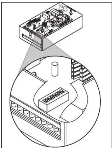
natural_image
Isometric diagram showing a computer interface with an electronic device and a circular layout of equipment (no text or symbols)NSF-approved Cleaning and Sanitizing Procedure
Cleaning and sanitizing should be performed at least every 6 months (more often if local water conditions dictate).

WARNING!
- Place the dispenser in Maintenance Mode prior to servicing or cleaning the ice machine. See Maintenance/Cleaning Mode on page 12.
- For protection, rubber gloves and safety goggles (and/or face shield) should be worn when handling SafeCLEAN Plus™.
- Do not use bleach, it will damage the dispenser.
Required Supplies
- 7 Series: 21 oz. (0.621 L) or 3 packets SafeCLEAN Plus
15 Series: 42 oz. (1.24 L) or 6 packets SafeCLEAN Plus
■ Funnel and Bucket
Ice machine and Dispenser
- Dispense all the ice out of the unit.
- Press and hold maintenance/clean switch until displays in the user interface to enter Maintenance Mode.
- Remove (unscrew) chrome ice dispense chute (Fig. 14.1).
- Remove drip tray (Fig. 14.2).
- Remove (2) screws located behind the drip tray (Fig. 14.3).
- Move front panel and place on top or beside unit (Fig. 14.4).
-
Remove plug cap from the end of drain tube (Fig. 14.5) and lower tube to drain water into bucket. After the system has been drained of water replace plug cap in drain tube.
-
Secure tube in holder.
-
Remove cap from bin lid cover (Fig. 14.6).
-
Screw bin lid cover cap onto ice discharge chute (Fig. 14.7).
-
7 Series: Mix 21 oz. (0.621 L) or 3 packets SafeCLEAN Plus with three gallons (11.4 L) of water. 15 Series: Mix 42 oz. (1.24 L) or 6 packets SafeCLEAN Plus with six gallons (22.7 L) of water
-
Pour cleaning solution into bin lid access spout until solution reaches the spout neck.
-
Allow the solution to remain in unit for 15 minutes.
-
While machine is cleaning, remove top and right side panel to access and clean air-cooled condenser.
-
Submerge ice dispense chute in the remainder of solution for 2 minutes. Rinse with clean, potable water.
-
Drain system by lowering drain tube into bucket.
-
Secure drain tube into holder.
-
Fill and drain three times with potable water. Secure drain tube.
-
Place a bucket under the dispense chute and remove cap. Note: Some solution will remain and drain out when cap is removed. Reposition cap on bin lid spout.
-
Reinstall front panel, ice dispense chute, and drip tray.
-
Press and hold maintenance/clean switch to exit Maintenance Mode.
Fig. 14
NSF-approved Cleaning and Sanitizing Procedure (continued)
User Interface and Exterior Cabinet
- Press and release maintenance/clean switch so that only "FRESH FILTERED ICE AND WATER" displays in the user interface to enter Cleaning Mode (and disable dispensing).
- Plastic parts, including the user interface, can be cleaned with a non-abrasive glass cleaner. Clean stainless steel panels with stainless steel cleaner.
- Press and release maintenance/clean switch to put unit back into service.
Service
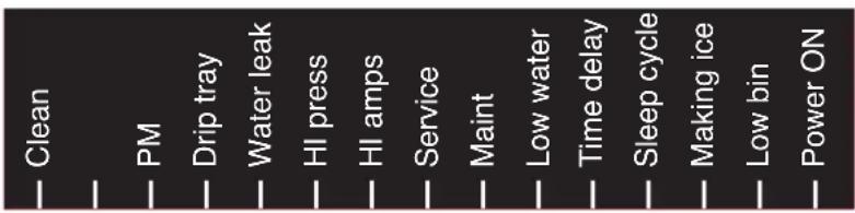
LED Indicator Description
The LED Indicator is located behind the front panel.
Fig. 15
| LED Name LED Color Description | ||
| Clean | Green | The dispenser is in Cleaning Mode. Dispenser is disabled to allow for cleaning of front panel.See Maintenance/Cleaning Mode on page 12. |
| — N/A Not used. | ||
| PM Red Six-month | periodic maintenance required. | |
| Drip tray | Red Drip tray full. | |
| Water leak | Red Internal leak in dispenser. | |
| High amps | Red | Auger gearmotor has exceeded 0.55A. The HI amps and Time delay LEDs will illuminate, the machine will shut down for one hour, the LEDs will turn off, and the machine will resume normal operation. |
| Service | Red | 8000 hour bushing check (call Follett technical service group at (877) 612-5086 or +1 (610) 252-7301). |
| Maintenance | Yellow | Enter Maintenance Mode by pressing and holding maintenance/clean switch for 5 seconds. Unit will not make or dispense ice. |
| Low water | Yellow | Insufficient water supply to machine or no low bin LED upon startup. |
| Time delay | Yellow | Ice production will not resume for at least 15 minutes after a full bin is achieved and a minimum amount of dispense activity has elapsed. |
| Sleep cycle | Green | After a full bin and 10 minutes of non-use, the unit goes into standby and will not produce ice until either:7 Series:12 hours has elapsed, 15 Series: 4 hours has elapsed or ice or water has dispensed. |
| Making ice | Green Gearmotor, compressor, and fan motor energized. | |
| Low bin | Green Bin switch closed calling for ice. | |
| Power on | Green Power supplied to unit. | |
Service (continued)
Evaporator Disassembly
- Disconnect power from the dispenser.
- Turn off water supply to dispenser.
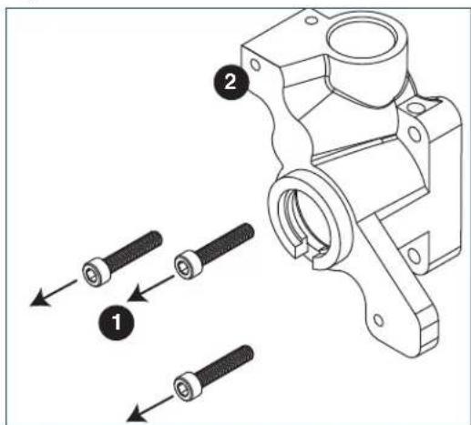
- Remove (unscrew) chrome ice dispenser chute (Fig. 16.1).
- Remove the drip tray (Fig. 16.2).
- Remove the two screws (Fig. 16.3) on the front panel (behind the drip tray).
- Remove and set aside the front panel (Fig. 16.4) - do not disengage the plug on the back of the User Interface.
- Lift and remove the top panel, set aside (Fig. 16.5).
- Remove two screws (Fig. 16.6) and remove left side panel.
- Remove two screws (Fig. 16.7) and remove right side panel.
Fig. 16
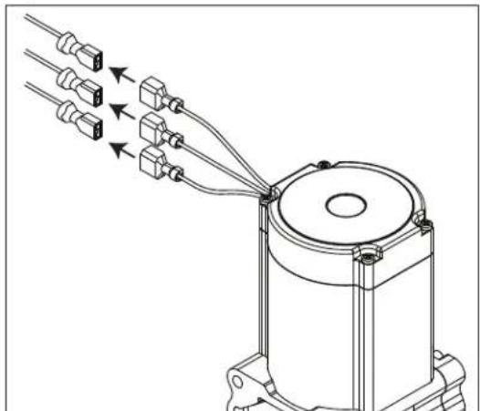
Service (continued)
- Unplug the gear motor (three connectors) (Fig. 16).
-
Remove ground screw connection.
-
Remove gear motor:
-
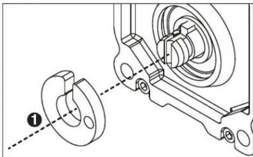
Remove M6 allen screw, retainer, spacer and key (Fig. 18.1).
■ Remove two M6x90 allen screws (Fig. 18.2). -
Pull gear motor from auger (Fig. 18.3).
■ Remove main housing insulation (Fig. 18.4). -
Remove all traces of petro-gel from auger shaft.
-
Remove compression nozzle:
■ Loosen hose clamp (Fig. 19.1).
■ Remove transport tube (Fig. 19.2).
Fig. 17
natural_image
Technical line drawing of a mechanical assembly with multiple connectors and wiring (no text or symbols)Fig. 18
Fig. 19
Service (continued)
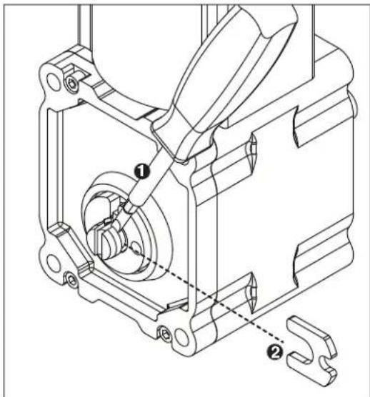
- Remove M6 socket head allen screw (Fig. 20.1).
- Remove compression nozzle retainer (Fig. 20.2).
-
Remove compression nozzle (Fig. 20.3).
-
Remove main housing:
■ Disconnect vent line from T fitting (Fig. 21.1).
- Remove three M6x25 socket head allen screws (Fig. 22.1).
- Remove main housing (Fig. 22.2).
Fig. 20
Fig. 21
Fig. 22
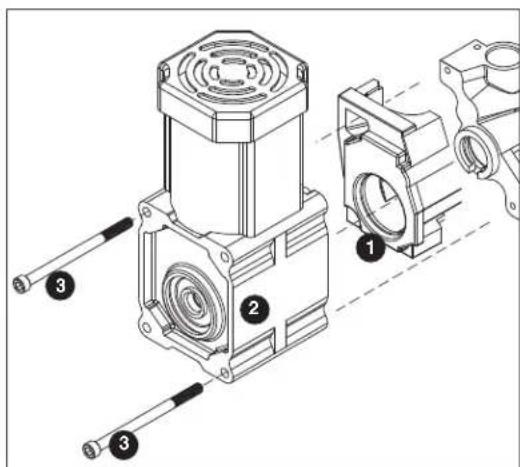
Service (continued)
-
Remove and discard mating ring and seal (Fig. 23.1).
-
Carefully remove auger (Fig. 23.2).

WARNING!
Use caution when removing auger. The auger is very sharp - handle with care to avoid personal injury.
Evaporator Assembly
- Remove and inspect main housing O-ring seal. Replace if damaged in any way.
- Clean O-ring groove. Lubricate O-ring with Petro-gel and reinstall.
- Use cardboard disc to press new mating ring into main housing (Fig. 24.1).
- Lube the shaft with liquid soap in the area shown (Fig. 24.2) and slip on seal and spring (Fig. 24.3).
Note: Do not touch the sealing surfaces with bare hands. Contact with bare skin will cause premature seal failure.
- Install auger (Fig. 24.4).
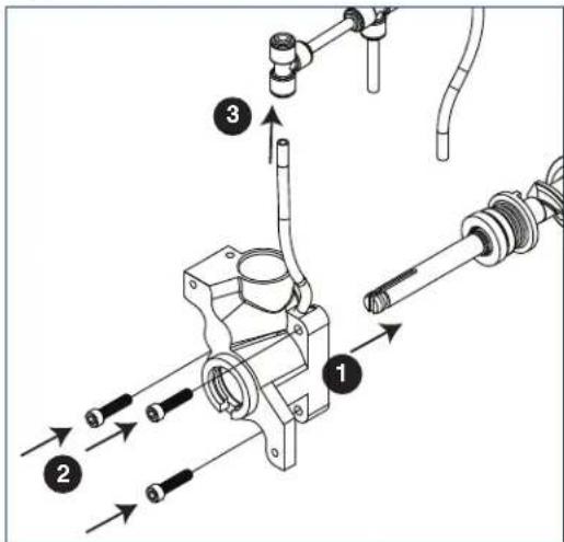
- Install main housing:
■ Slide main housing onto auger shaft (Fig. 25.1).
- Install three M6x25 allen screws (Fig. 25.2).
- Connect vent line to T fitting (Fig. 25.3).
Fig. 23
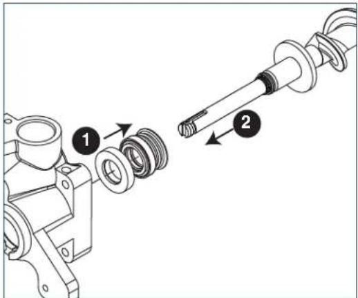
Fig. 24
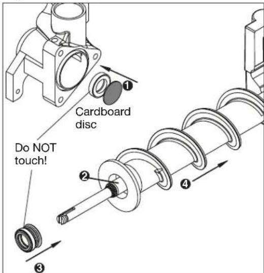
Fig. 25
Service (continued)
-
Install compression nozzle:
-
Remove and inspect compression nozzle O-ring seal. Replace if damaged in any way.
- Clean O-ring groove. Lubricate O-ring with Petro-gel and reinstall.
■ Install compression nozzle (Fig. 26.1). - Install compression nozzle retainer (Fig. 26.2).
-
Install M6 socket head allen screw (Fig. 26.3).
-
Install transport tube (Fig. 27.1).
-
Tighten hose clamp (Fig. 27.2).
-
Install gear motor:
-
Install main housing insulation (Fig. 28.1).
■ Slide gear motor onto auger shaft (Fig. 28.2). - Install two M6x90 allen screws (Fig. 28.3).
Fig. 26
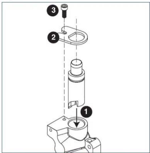
Fig. 27
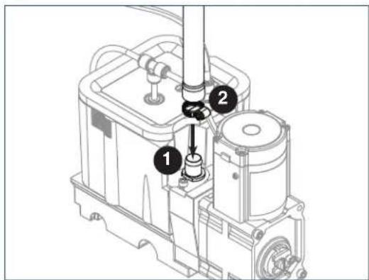
Fig. 28
Service (continued)
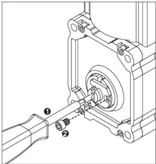
- Use screwdriver to orient auger shaft to align with motor shaft keyway (Fig. 29.1).
-
Install key into keyway (Fig. 29.2).
-
Install spacer, ensure that key is captured in slot (Fig. 30.1)
-
Insert screwdriver into groove of auger shaft and pry shaft outwards (Fig. 31.1).
- Insert retainer into groove (Fig. 31.2), ensure that retainer is aligned with hole in spacer.
Fig. 29
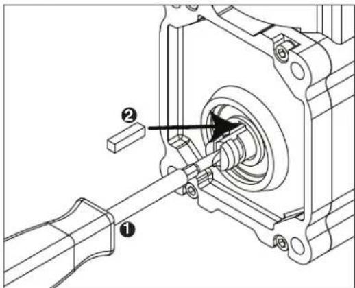
Fig. 30
natural_image
Technical line drawing of a mechanical assembly with two views: one showing a flange and the other showing a bearing housing (no text or symbols)Fig. 31
Service (continued)
- Install screw and tighten (Fig. 32.1).
Fig. 32
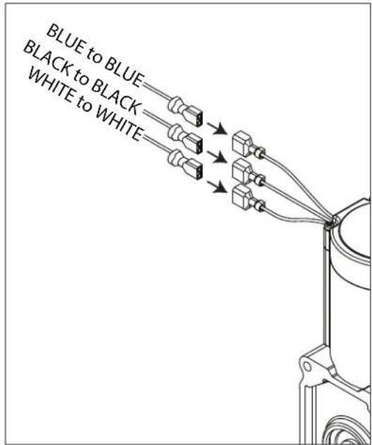
- Plug in gear motor (Fig. 33).
BLUE to BLUE
- BLACK to BLACK
- WHITE to WHITE
■ Connect ground wire with ground screw.
Fig. 33
Service (continued)
Water Feed Schematic
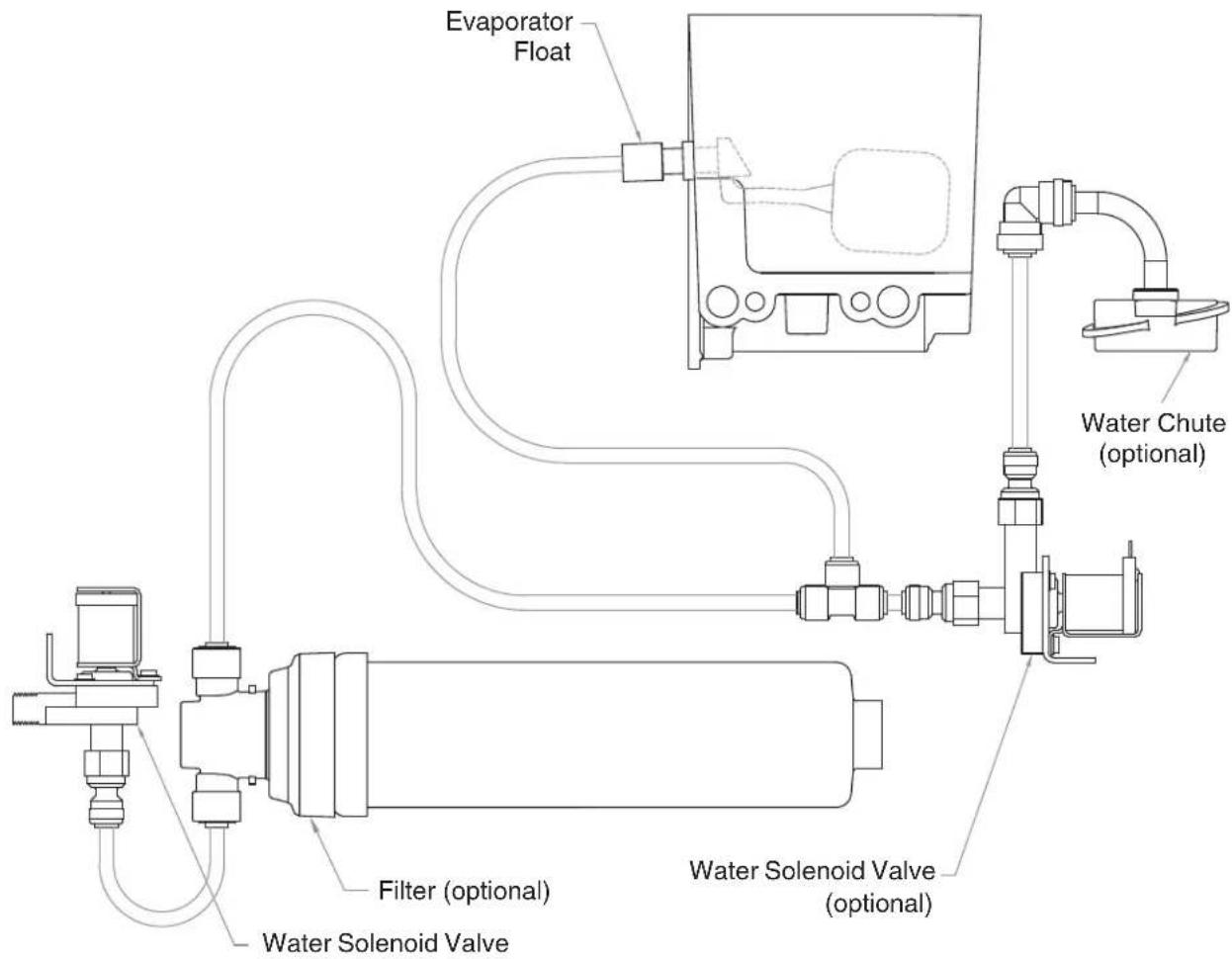
flowchart
graph TD
    A["Evaporator Float"] --> B["Water Solenoid Valve (optional)"]
    B --> C["Water Chute (optional)"]
    C --> D["Filter (optional)"]
    D --> E["Water Solenoid Valve"]
    E --> F["Internal Component"]
    style A fill:#f9f,stroke:#333
    style B fill:#ccf,stroke:#333
    style C fill:#cfc,stroke:#333
    style D fill:#fcc,stroke:#333
    style E fill:#cff,stroke:#333
    style F fill:#ffc,stroke:#333
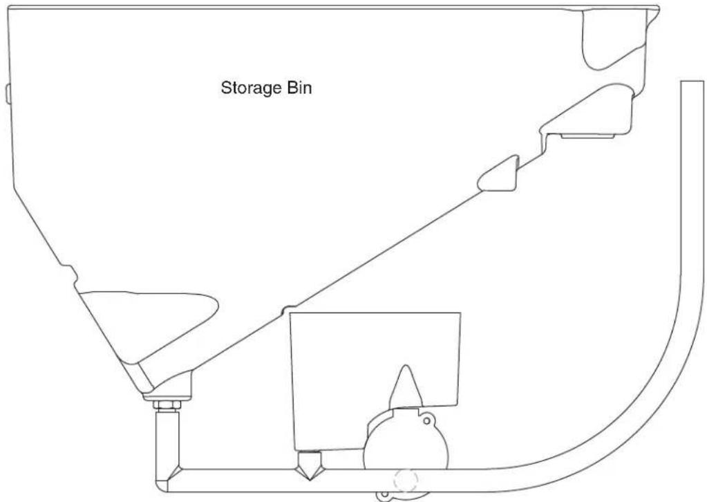
Bin Melt Water/Evaporator Feed/Clean Out System Schematic
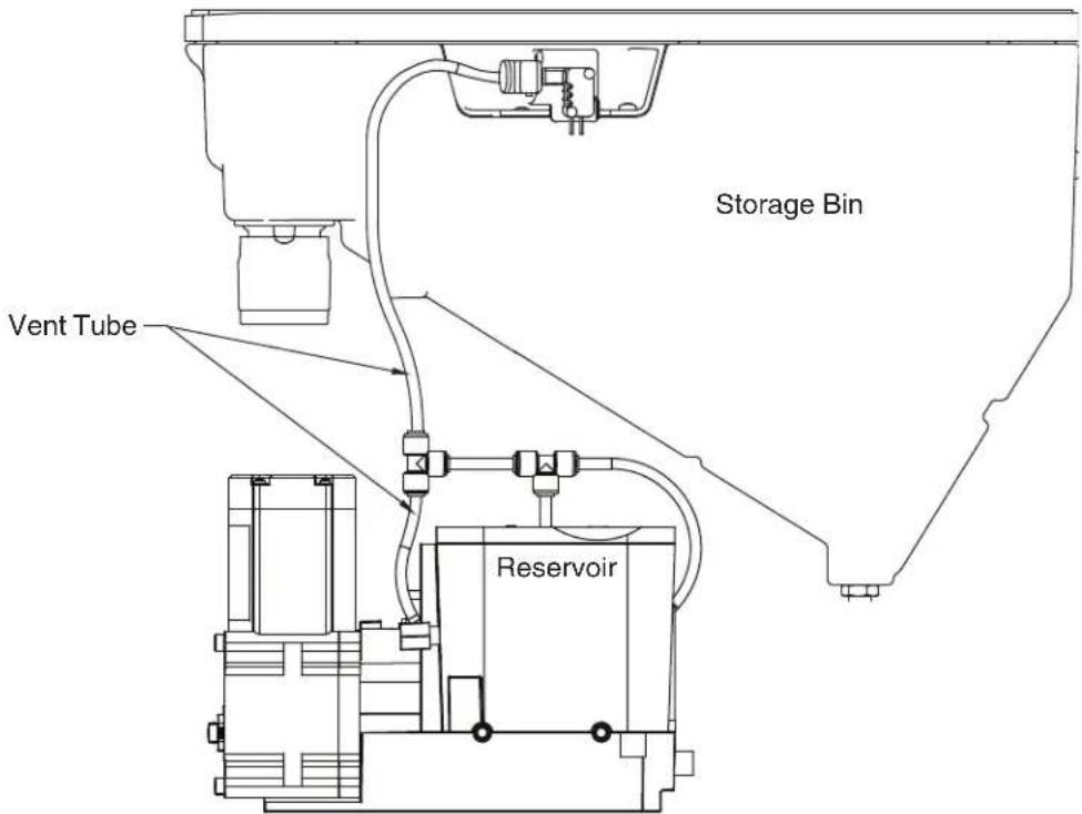
Vent System Schematic
Refrigeration Schematic
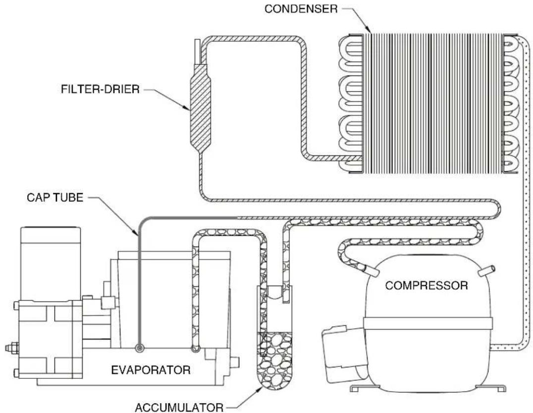
HIGH PRESSURE VAPOR

LOW PRESSURE LIQUID
HIGH PRESSURE LIQUID LOW PRESSURE VAPOR
Condenser Fan Motor Removal (7 Series Shown)
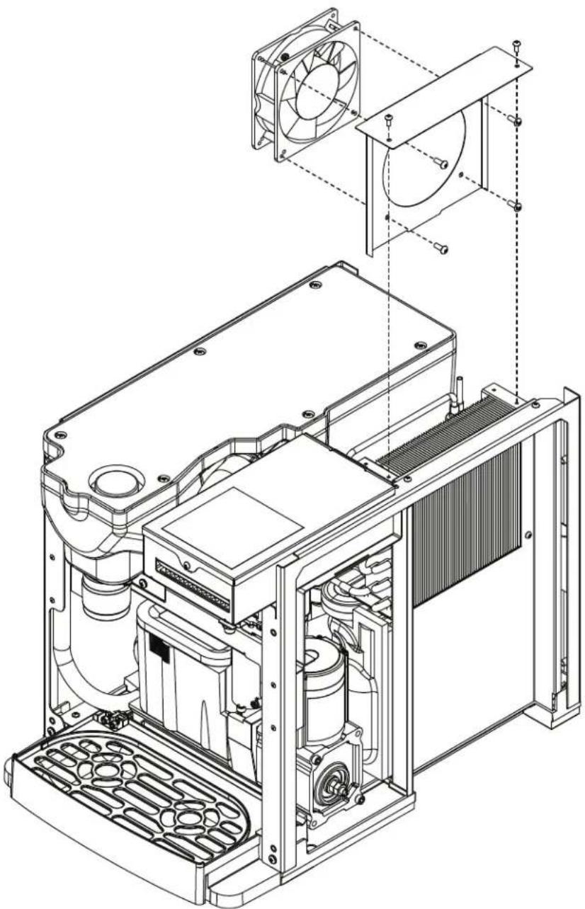
natural_image
Technical line drawing of an internal combustion engine unit with fan and cooling fins (no text or labels)User Interface Display Identification
| Operation Display | Condition | Procedure |
 FRESH FILTERED ICE AND WATER FRESH FILTERED ICE AND WATER  | Normal operation | — |
 | Cleaning Mode Press and release maintenance/clean switch to clean the user interface without dispensing ice or water (see Maintenance/Cleaning Mode on page 12). | |
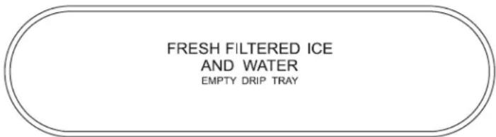 | Drip tray full Empty drip tray. | |
 | Six-month periodic maintenance required | Follow Maintenance Mode procedure (below) and also see NSF-approved Cleaning and Sanitizing Procedure on page 14. |
 | Maintenance Mode | Enter Maintenance Mode by pressing maintenance/clean switch until displays. Complete the cleaning and sanitizing procedure shown on page 14 and change the filter, if so equipped. Exit Maintenance Mode by pressing and holding maintenance/clean switch until no longer displays. |
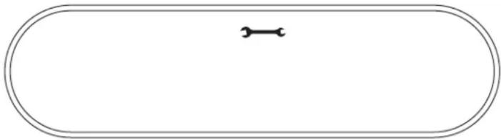
 | Service - 8000 hr bushing check | Call Follett Technical Service Group at (877) 612-5086 or +1 (610) 252-7301. The flashing wrench indicates that the 8000 hr bushing check is required. |
Service (continued)
| Service Display Condition Procedure | ||
 | High amps Contact Follett technical service group at (877) 612-5086 or +1 (610) 252-7301. Note: For dispensers after serial number D45191, the phone and wrench will not be illuminated. | |
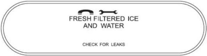 | Internal leak in dispenser | Locate leak and repair - Press reset on control board. Contact Follett if icemaker is leaking. |
 | Sleep mode Press either dispense button to return to normal operation. | |
Electrical Wiring Diagram
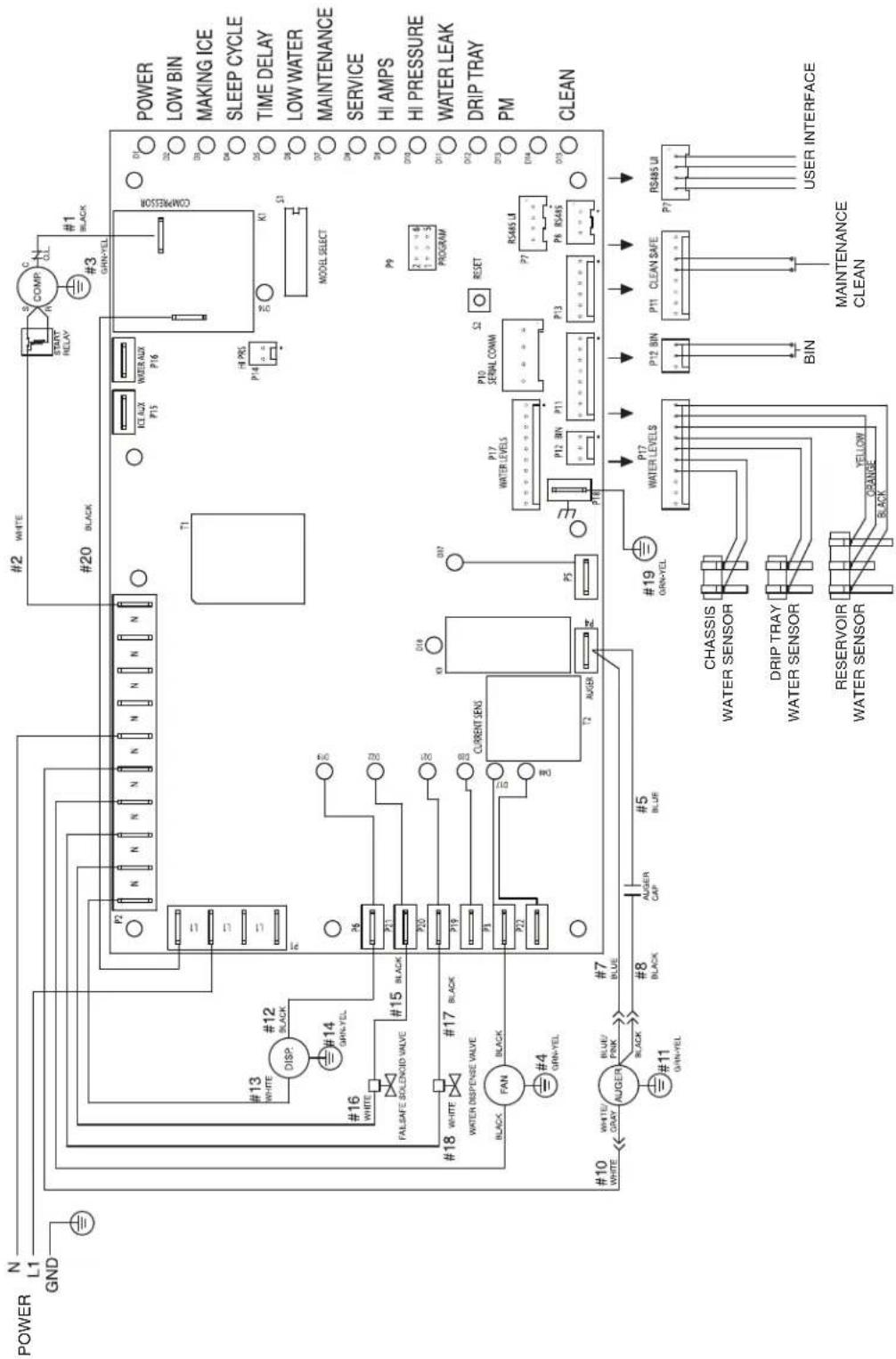
flowchart
graph TD
    A["POWER"] --> B["N L1 GND"]
    B --> C["#13 WHITE DISP. #12 BLACK"]
    C --> D["#16 WHITE FALSAFE SOLICOID VALVE #15 BLACK"]
    D --> E["#18 WHITE WATER DISPENSE VALVE #17 BLACK"]
    E --> F["#10 WHITE AUGER BLUE/PINK #7 BLACK #8 BLACK CAP #5 BLUE"]
    F --> G["#11 GRIN-YEL #19 CHASSIS WATER SENSOR"]
    G --> H["RESERVOIR WATER SENSOR YELLOW BLACK"]
    H --> I["T1 P2 N N N N N N N N N N"]
    I --> J["PI2 P15 P16"]
    J --> K["ICL AUX P15"]
    K --> L["POWER AUX P16"]
    L --> M["HI PRS P14"]
    M --> N["K1"]
    N --> O["MODEL SELECT"]
    O --> P["POWER LOW BIN MAKING ICE SLEEP CYCLE TIME DELAY LOW WATER MAINTENANCE SERVICE HI AMPS HI PRESSURE WATER LEAK DRIP TRAY PM CLEAN"]
    P --> Q["P9 2: 4 5 PROGRAM"]
    Q --> R["RESET"]
    R --> S["P10 SERIAL COMM"]
    S --> T["P12 BIN P11"]
    T --> U["P13"]
    U --> V["P17 WATER LEVELS"]
    V --> W["P19 RS485 UI"]
    W --> X["P12 BIN BIN"]
    X --> Y["P11 CLEAN SAFE"]
    Y --> Z["P7 RS485 UI"]
    Z --> AA["USER INTERFACE"]
Parts
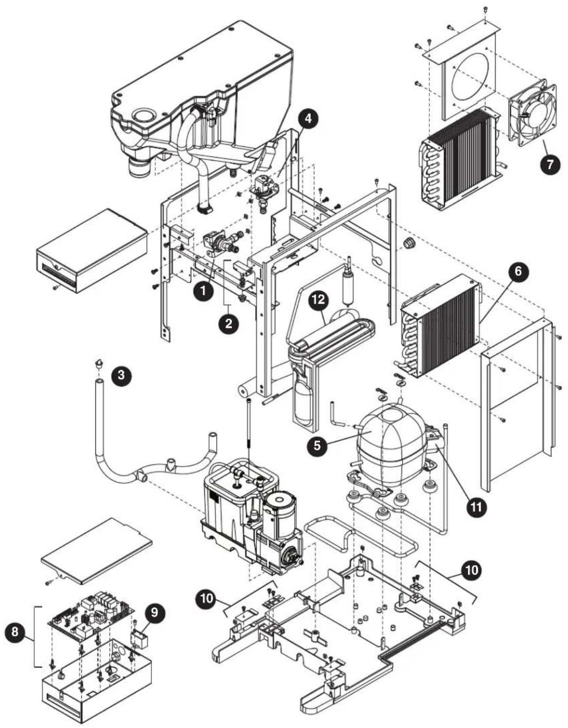
7 Series Exterior
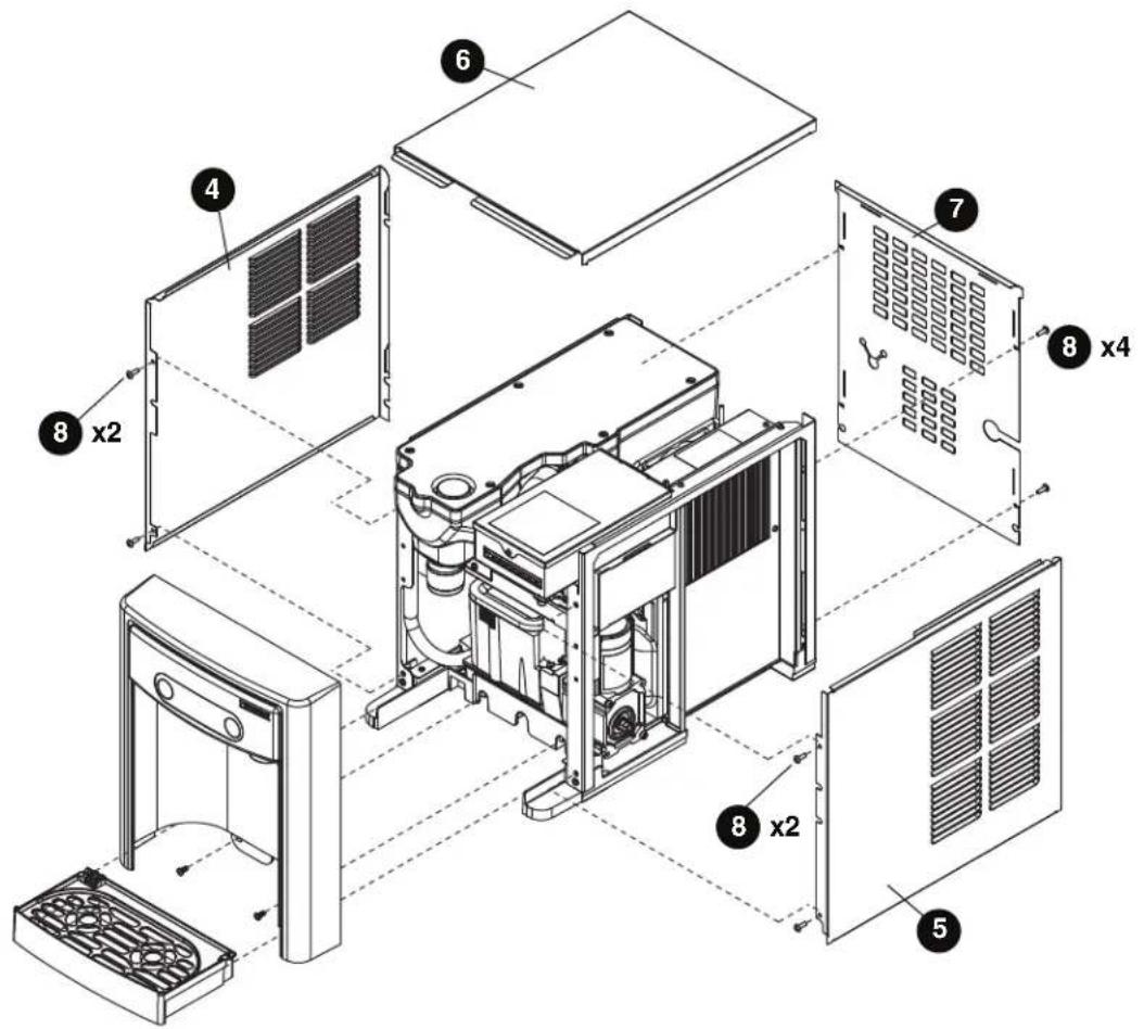
Parts (continued)
Exterior
| Reference # Description Part # | ||
| 1 Drip Tray Assy 00957613 | ||
| 2 Panel, Front Assy - Includes Water Nozzle and Plug 00957621 | ||
| 3 Chute, Water (water option) 00957688 | ||
| 4 Panel, Left 00932806 | ||
| 5 Panel, Right 00932798 | ||
| 6 Panel, Top 00957654 | ||
| 7 Panel, Rear 00933911 | ||
| 8 Screw, M5 x 12 Phillips 00931931 | ||
| Not Shown | Cord, 115 VAC | 00958058 |
| Not Shown | 7 Series Packaging for Returns, Dispenser | 00957993 |
| Not Shown | Fitting, Elbow - 1/4" FPT x 1/4" Tube | 00974261 |
| Not Shown | Drip Tray Drain Kit | 00956375 |
| Not Shown | Drip Tray Drain Kit with 4" legs | 00981977 |
Parts (continued)
7 Series Interior
Parts (continued)
Interior
| Reference # Description Part # | ||
| 1 Valve, Dispense Solenoid (water option) 00957704 | ||
| 2 Switch, Cleaning 00957712 | ||
| 3 Drain/Feed Tube with Cap 00957720 | ||
| 4 Valve, Failsafe Solenoid 00957738 | ||
| 5 Compressor with Mounting Hardware 00958009 | ||
| 6 Condenser 00958017 | ||
| 7 Condenser Fan and Cord 00958025 | ||
| 8 Control Board with Stand-offs 00958033 | ||
| 9 Capacitor, Gearmotor | 00958041 | |
| 10 | Sensor, Retainer Hardware Kit | 00958066 |
| 11 | Relay and Overload | 00958090 |
| 12 | Refrigeration, Piping Assy | 00958132 |
15 Series Exterior
Parts (continued)
Exterior
| Reference # Description Part # | ||
| 1 Drip Tray Assy 00957613 | ||
| 2 Panel, Front Assy - Includes Water Nozzle and Plug 01036425 | ||
| 3 Chute, Water (water option) 00957688 | ||
| 4 Panel, Left 01026343 | ||
| 5 Panel, Right 01026335 | ||
| 6 Panel, Top 01054733 | ||
| 7 Panel, Rear 01025980 | ||
| 8 Screw, M5 x 12 Phillips 00931931 | ||
| Not Shown | Cord, 115 VAC | 00958058 |
| Not Shown | 15 Series Packaging for Returns, Dispenser | 01054634 |
| Not Shown | Fitting, Elbow - 1/4" FPT x 1/4" Tube | 00974261 |
| Not Shown | Drip Tray Drain Kit | 00956375 |
| Not Shown | Drip Tray Drain Kit with 4" legs | 00981977 |
| Not Shown | Covers, Agion, User Interface | 00969030 |
Parts (continued)
15 Series Interior
Parts (continued)
Interior
| Reference # Description Part # | ||
| 1 Valve, Dispense Solenoid (water option) 00957704 | ||
| 2 Switch, Cleaning 00957712 | ||
| 3 Drain/Feed Tube with Cap 00957720 | ||
| 4 Valve, Failsafe Solenoid 00957738 | ||
| 5 Compressor with Mounting Hardware 00958009 | ||
| 6 Condenser 00958017 | ||
| 7 Condenser Fan and Cord 00958025 | ||
| 8 Control Board with Stand-offs 01051978 | ||
| 9 Capacitor, Gearmotor | 00958041 | |
| 10 | Sensor, Retainer Hardware Kit | 00958066 |
| 11 | Relay and Overload | 00958090 |
| 12 | Refrigeration, Piping Assy | 00958132 |
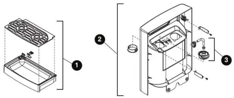
7 Series Bin Assembly
7 Series Bin Assembly
| Reference # Description Part # | ||
| 1 Ice Chute Assembly 00957670 | ||
| 2 Ice Transport Tubing with Insulation 00957746 | ||
| 3 Switch, Shuttle 00957753 | ||
| 4 Shuttle, Complete Assy 00957761 | ||
| 5 Lid, Bin Assy 00957779 | ||
| 6 Bin, Assy 00957787 | ||
| 7 Auger, Dispense 00931113 | ||
| 8 Motor, Dispense | 00957803 | |
| 9 Cap and Insulation, Bin | 00957936 | |
| Not Shown | For serial numbers D17619 and below: | |
| Bin Cap | 00931519 | |
| Ice Chute | 00927210 | |
| Chute Adapter | 00926550 | |
Parts (continued)
15 Series Bin Assembly
Parts (continued)
15 Series Bin Assembly
| Reference # Description Part # | ||
| 1 Ice Chute Assembly 01051846 | ||
| 2 Ice Transport Tubing with Insulation 01051960 | ||
| 3 Switch, Shuttle 00957753 | ||
| 4 Shuttle, Complete Assy 01053248 | ||
| 5 Lid, Bin Assy 01053255 | ||
| 6 Bin, Assy 01053263 | ||
| 7 Auger, Dispense 01026251 | ||
| 8 Motor, Dispense | 00957803 | |
| 9 Cap and Insulation, Bin | 01053305 |
Evaporator Assembly
Evaporator Assembly
| Reference # Description Part # | ||
| 1 Gearmotor Assy 00957811 | ||
| 2 Main Housing with Front Seal and Screws 00957829 | ||
| 3 Screws, Main Housing 00957837 | ||
| 4 Auger with front seal 00957845 | ||
| 5 Ice Compression Nozzle Assy 00957852 | ||
| 6 Front Seal and O-Ring 00957860 | ||
| 7 Evaporator Assembly with Insulation 00957878 | ||
| 8 Housing, Bushing with Insulation 00957886 | ||
| 9 | Hardware kit, Gearmotor (For serial numbers E01087 and above) | 01048628 |
| 9 | Hardware kit, Gearmotor (For serial numbers below E01087) | 00957894 |
| 10 | Reservoir and Float Complete Assy | 00957902 |
| 11 | Lid, Reservoir with Insulation and O-Ring | 00957910 |
| 12 | Float Valve | 00957928 |
| 13 | “T” Fitting - 1/4" | 502923 |
| 14 | Tubing - 1/4" (sold in 12" increments) | 502079 |
Parts (continued)
Base Stand
Parts (continued)
Base Stand
| Reference # Description Part # | ||
| 1 Front Panel, Base 00958108 | ||
| 2 Latches with Bayonets, Base 00958116 | ||
| Not Shown Tray, Base 00958124 | ||
| Not Shown Packaging for Returns, Base 00957985 |
Miscellaneous
| Reference # Description Part # | |
| Not Shown Water filter cartridge, 5 micron 00968107 | |
| Not Shown IMS II sanitizer concentrate, 16 oz 00979674 | |
| Not Shown SafeCLEAN Plus, 3 pack 01054683 | |
| Not Shown SafeCLEAN Plus, 6 pack 01054691 | |
| Not Shown SafeCLEAN Plus, case of 24 01050863 | |
| Not Shown 6" Legs for base stand, set of 4 | 00956318 |
| Not Shown 4" Legs for countertop dispenser, set of 4 | 00956300 |
SafeCLEAN and SafeCLEAN Plus are trademarks of Follett Corporation. Chewblet and Follett are registered trademarks of Follett Corporation, registered in US.