
ZKX6550V - Security Camera ZKTeco - Free user manual and instructions
Find the device manual for free ZKX6550V ZKTeco in PDF.


| Product Type | Security Camera |
| Brand | ZKTeco |
| Model | ZKX6550V |
| Image Sensor | 1/2.8" Progressive Scan CMOS |
| Resolution | 5MP (2592 x 1944) |
| Lens | 2.8mm Fixed Lens |
| Night Vision | Up to 30m IR Distance |
| Power Supply | DC 12V / PoE (802.3af) |
| Power Consumption | ≤ 7W (Max) |
| Operating Temperature | -10°C to 55°C (14°F to 131°F) |
| Dimensions (W x H x D) | 76 x 76 x 139 mm |
| Weight | 0.45 kg (1.0 lb) |
| Weatherproof Rating | IP67 |
| Mounting Type | Ceiling / Wall Mount |
| Video Compression | H.265 / H.264 / MJPEG |
| Network Interface | 10/100 Base-T Ethernet (RJ-45) |
| Audio | Built-in Microphone and Speaker |
| Storage | MicroSD Card (up to 128GB) / NVR |
| Motion Detection | Yes (Digital Input) |
| Viewing Angle | Horizontal: 102°, Vertical: 55° |
| Material | Aluminum Alloy |
| Color | White |
| Certifications | CE, FCC, RoHS |
| Additional Features | ONVIF (Profile S/G/T) Compliant |
Frequently Asked Questions - ZKX6550V ZKTeco
User questions about ZKX6550V ZKTeco
0 question about this device. Answer the ones you know or ask your own.
Ask a new question about this device
Download the instructions for your Security Camera in PDF format for free! Find your manual ZKX6550V - ZKTeco and take your electronic device back in hand. On this page are published all the documents necessary for the use of your device. ZKX6550V by ZKTeco.
USER MANUAL ZKX6550V ZKTeco
X-ray Security Inspection System
Maintenance Manual
Version: 1.0 Date: November 2017






First of all, thank you for your trust in ZKTECO and selection of our "security inspection" product! This product is subject to strict quality control. Although the components have long service life, the ageing of roller bearing and wear of conveying belt are inevitable during operation, which will not lead to the stop of equipment but will increase the failure rate. It is recommended to conduct regular maintenance in order to ensure normal operation.
We will sincerely provide high-quality maintenance services, with good attitude, professional technician team (the members have received the regular and rigorous technical training and obtained appropriate certificates) and original component sources.
The products may be improved or upgraded without prior notice. The equipment structure and circuit may differ from that in kind. Your understanding and support will be appreciated.
Contents
- Simple Faults and Troubleshooting....1
1.1 Failure of Startup after Powering-on....1
1.2 Red "Emergency" in Lower Right Corner of LCD (Computer Display) and Failure of Roller Motor (Fig. 1-4)....2
1.3 No Image of "Inspected Bag" during Normal Operation....3
1.4 Red "System Error" in the Lower Right Corner of LCD (Computer Display) after Startup 4
1.5 Failure of AC Roller Motor (if any) of Belt during Normal Operation....6
- Component Replacement....7
2.1 Relay Replacement....7
2.2 Contactor Replacement....8
2.3 Replacement of Roller Motor Controller (for 5030)....9
2.4 Fuse Replacement....9
2.5 Replacement of Emergency Stop Button....10
2.6 Indicator Replacement....11
2.7 Replacement of Key Switch and Start Button 12
2.8 Replacement of Air Switch....13
2.9 Replacement of Roller Motor 15
2.10 Replacement of Driven Roller 16
2.11 Replacement of Supporting Roller....17
2.12 Replacement of X-ray Generator 18
2.13 Replacement of Lead Curtain....19
2.14 Replacement of Conveyor Belt....20
- Control Board PCBA, X-ray Generator LED Indicator and Interface 21
3.1 Interface of Control Board PCBA....21
3.2 LED Indicator and Interface of X-ray Generator 23
- Interpretation of Electrical Diagram....25
4.1 Interpretation of Electrical Diagram....25
- Maintenance....30
5.1 Dust Removal 30
5.2 Component Replacement....33
1. Simple Faults and Troubleshooting
1.1 Failure of Startup after Powering-on
If the equipment cannot be started normally, first check the power voltage (normally AC 200V-240V) (Fig. 1-1). In the case of no or abnormal voltage, check the power supply circuit until the voltage is normal. If the voltage is normal but the equipment cannot be started, check whether the voltage between the terminals 1 and 3 is 200V-240V (Fig. 1-2). If the anomaly still occurs, check whether the air switch trips and whether the fuse is broken. Replace the broken fuse (Fig. 1-3). Then check whether the plug in the power outlet is installed properly. If the above components are in good conditions but the equipment cannot be started normally, please call the repair personnel of the manufacturer.
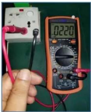
Fig. 1-1
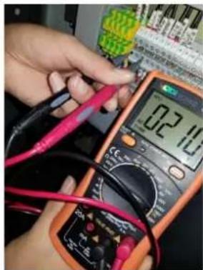
Fig. 1-2
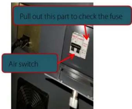
Fig. 1-3
1.2 Red "Emergency" in Lower Right Corner of LCD (Computer Display) and Failure of Roller Motor (Fig. 1-4)
In the above case, first check whether the "Emergency Stop Button" is pressed. Normally, two "Emergency Stop Buttons" are provided (Fig. 1-5). If the console is provided, there is an "Emergency Stop Button" on its "Special Keyboard". Release the pressed emergency stop button by rotating it clockwise, and then press "Start" to restore normal operation. If "Emergency" is still displayed, check two "Micro Switches". Under normal circumstances, the two "Side Doors" in the tightened state will be against the "Micro Switches" (Fig. 1-6). The "Emergency" fault may occur if one "Side Door" is not against the "Micro Switch" as a result of loosening. Eliminate the fault, and press "Start" to restore normal operation. If the above items are in good conditions but the equipment does not work normally, please call the repair personnel of the manufacturer.
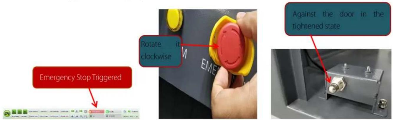
Fig. 1-4
Fig. 1-5
Fig. 1-6
1.3 No Image of "Inspected Bag" during Normal Operation
If the equipment works normally but the image of the "inspected bag" is not displayed, check whether the "Optical Path" (small hole of the iron plate and surfaces of the transmitting and receiving ends of the photoelectric switches) of the photoelectric switches is blocked by debris such as dust during long-term operation. If necessary, remove the photoelectric switches (Fig. 1-7 and 1-8), clean the "Optical Path", and reinstall the photoelectric switches (note: clean two photoelectric switches, as they are used as a pair). Then restart the equipment. If the image is still abnormal and the red text "System Error" (Fig. 1-9) appears in the lower right corner of the LCD (computer display), refer to Section 1.4.
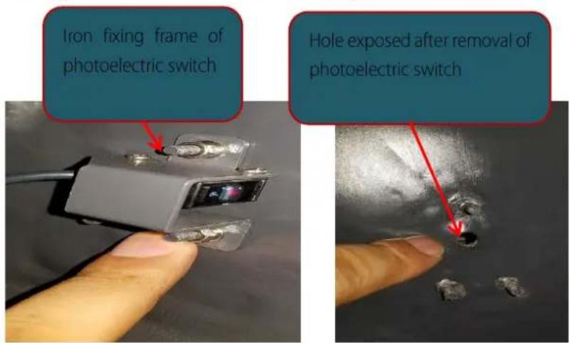
Fig. 1-7

Fig. 1-8
Fig. 1-9
1.4 Red "System Error" in the Lower Right Corner of LCD (Computer Display) after Startup
This may be caused by the fault of "transmission system" and "control panel connection".
Double-click "System Error". If "Sensor link error" appears (Fig. 1-10), it indicates that the power or transmission network cable of the "Transmission Board" (in the small iron box beside the "L-shaped Frame") is faulty. Check whether the power plug on the "Transmission Board" (Fig. 1-11) is loose or in poor contact, and pull out and insert it again. Check whether the plug of the transmission network cable is in good conditions, and pull out and insert again this plug and the network cable plug of IPC (industrial personal computer) board (Fig. 1-12). Restart the equipment. If the fault is still not eliminated, please call the repair personnel of the manufacturer.
![Sensor link error System Check failed: the information Control: external open failed Sensor link error OK [P1] Cancel [P2]](/content/2026/05/1058261/images/c0cf94ad325931d658ef8dc6bfaa31076b2f2408eabd5e593ad56d378c560ee3.jpg)
Fig. 1-10
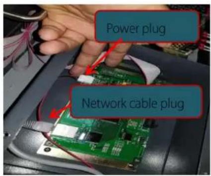
Fig. 1-11
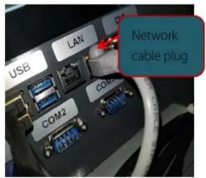
Fig. 1-12
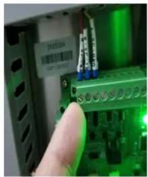
Double-click "System Error". If the control board connection is incorrect (Fig. 1-13), check whether the power interface of the control board is in poor contact (Fig. 1-14), whether the voltage (DC 12V) is normal, whether the connecting cable between the control board and IPC is connected improperly (Fig. 1-15), and whether the COM1 interface of IPC is loose (Fig. 1-16). If the fault still exists after the above troubleshooting and restart, please call the repair personnel of the manufacturer.
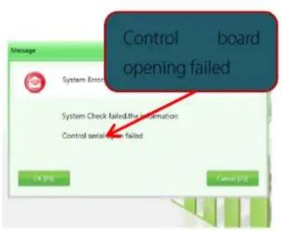
Fig. 1-13
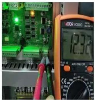
Fig. 1-14
natural_image
Close-up of a finger pressing a green circuit board with blue connectors (no visible text or symbols)Fig. 1-15
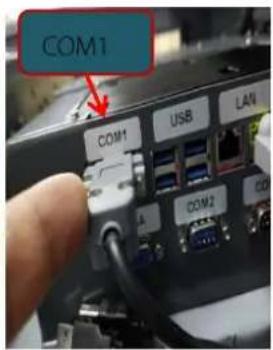
Fig. 1-16
1.5 Failure of AC Roller Motor (if any) of Belt during Normal Operation
Check whether the "Overcurrent Protector" (DZ108-20) trips (that is, overcurrent tripping, generally caused by overload). This fault can be recovered manually (press the ON button of DZ108-20, as shown in Fig. 1-17). As the thermal element is used, you should wait for a moment before pressing this button. Once this button is pressed, the motor will work normally. If the thermal element is triggered (the roller motor is hot, subject to overcurrent arising from overload), normal operation will be recovered in a few minutes. If the above items are checked but the roller motor still fails, please call the repair personnel of the manufacturer.
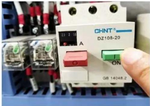
Fig. 1-17
Pay attention to the safety. All components must be replaced with the power supply disconnected (OFF)! The belt tightness and balance must be adjusted (to avoid deviation) after the belt, roller motor, supporting roller and driven roller are replaced.
2. Component Replacement
2.1 Relay Replacement
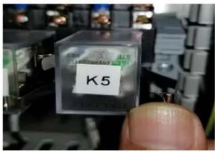
Fig. 2-1
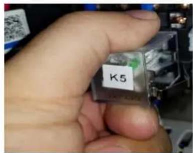
Fig. 2-2
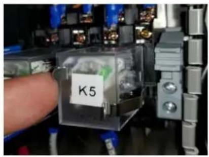
Fig. 2-3
The 240VAC and 10A relay (model: JQX-13F 2Z; brand: DELIXI), with two groups of normally closed contacts, two groups of normally open contacts and coil voltage of DC 12V, is used. The replacement process is as follows: remove the snap spring and relay (Fig. 2-1 and 2-2), and reinstall the relay and snap spring (Fig. 2-3).
2.2 Contactor Replacement
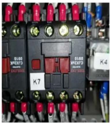
The CJX2sK-09 contactor (brand: DELIXI), with three groups of normally open main contacts, one group of normally open auxiliary contacts, contact current of 9A and coil voltage of AC 220V is used. The removal process is as follows: remove all connecting wires (Fig. 2-4), pull the contactor obliquely upwards by hand (Fig. 2-5) until it is separated from the upper edge of the guide rail, and then remove the contactor by gently pulling it down. The installation process is as follows: clamp the contactor bottom in the original position, pull the contactor up, then fix the contactor by pressing it, and finally connect all wires (Fig. 2-6). (Note: Connect the wires in the original positions. Otherwise, more serious faults may be caused!)
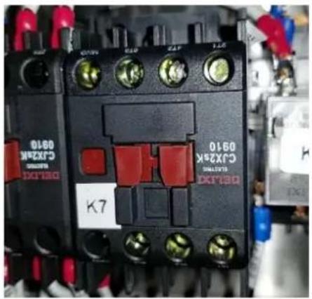
Fig. 2-4
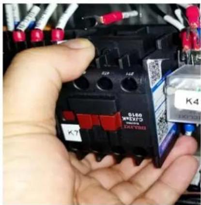
Fig. 2-5
natural_image
Close-up of an industrial electrical contactor with red and gold pins, no visible text or symbols on the main body.Fig. 2-6
2.3 Replacement of Roller Motor Controller (for 5030)
Remove the fixing screws (as shown in Fig. 2-7) of the roller motor controller, then remove the connecting wires with a screwdriver (Fig. 2-8). Install a new roller motor controller according to the opposite steps. (Note: Connect the wires in the original positions. Otherwise, more serious faults may be caused!)
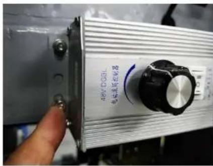
Fig. 2-9
2.4 Fuse Replacement
Open the fuse box, take out the fuse (Fig. 2-9), and install a new fuse.
2.5 Replacement of Emergency Stop Button
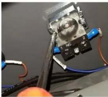
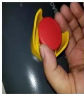
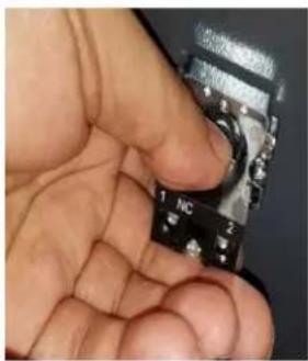
Remove the fixing screws and wire screws (Fig. 2-11) of the emergency stop button (Fig. 2-10). Rotate the button counterclockwise (Fig. 2-12), and hold the other end (Fig. 2-13) to remove it. Install a new button according to the opposite steps.
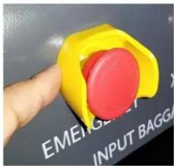
Fig. 2-10
natural_image
Close-up of a mechanical component with wires and a labeled component (no readable text or symbols)Fig. 2-11
natural_image
Hand holding a yellow and red toy object on a dark surface (no text or symbols visible)Fig.2-12
natural_image
Close-up of a hand holding a small electronic component with pins and a black body (no visible text or symbols)Fig. 2-13
2.6 Indicator Replacement
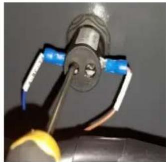
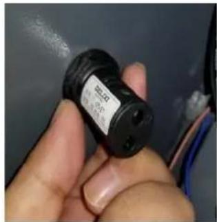
Take the power indicator as an example (Fig. 2-14). Remove the connecting wire (Fig. 2-15). Then remove the fastening ring behind the indicator by rotating it counterclockwise (Fig. 2-16). Install a new indicator according to the opposite steps.
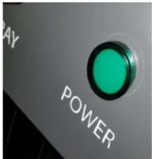
Fig. 2-14
natural_image
Close-up of a mechanical component with blue and yellow wires attached, no visible text or symbolsFig. 2-15
natural_image
Close-up of a hand holding a black cylindrical electronic component with a label, against a dark background (no readable text or symbols)Fig. 2-16
2.7 Replacement of Key Switch and Start Button
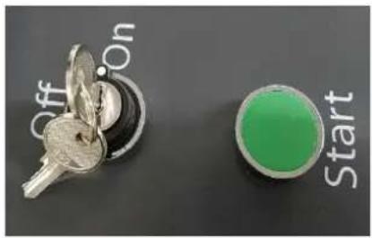
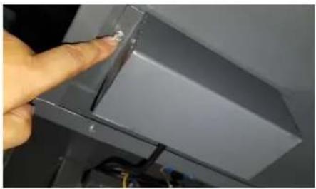
See Fig. 2-17 for the key switch and start button. Remove the plug (Fig. 2-18) of the connecting wire between the key and start button on the back of the top plate. Then remove the protective cover (Fig. 2-19). Refer to "Replacement of Emergency Stop Button" for specific replacement steps.
natural_image
Close-up of a metallic key and a green circular button labeled 'Start' on a dark surface (no other text or symbols visible)Fig. 2-17
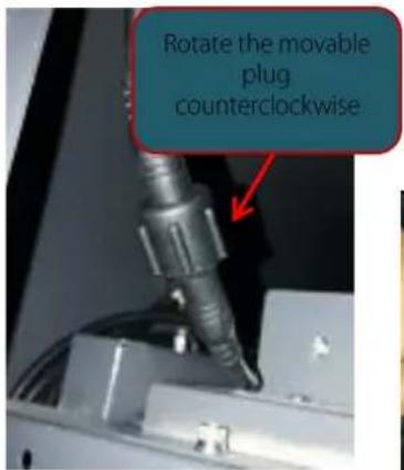
Fig. 2-18
natural_image
Close-up of a hand pointing at a metallic panel or fixture component (no visible text or symbols)Fig. 2-19
2.8 Replacement of Air Switch
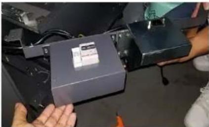
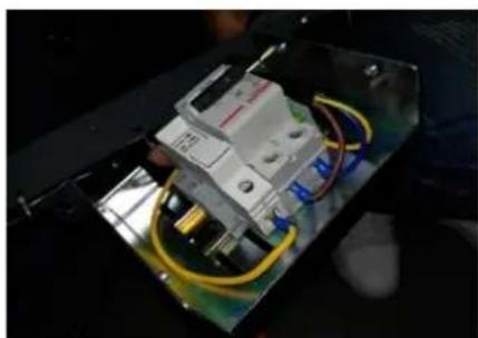
See Fig. 2-20 for the air switch. First remove all connecting wires of the light controller (Fig. 2-21) and four beam fixing screws. Then disconnect the strap (Fig. 2-22), take out the beam (Fig. 2-23), and remove the box (Fig. 2-24) and air switch (Fig. 2-25). Install a new air switch according to the opposite steps.
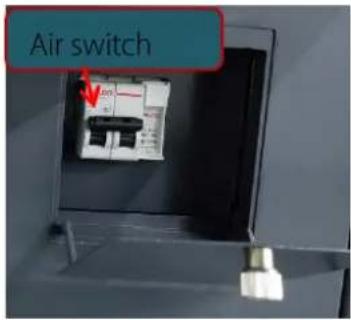
Fig. 2-20
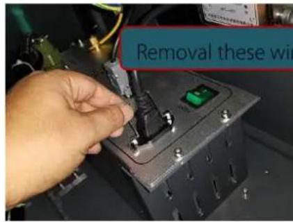
Fig. 2-21
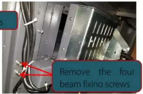
Fig. 2-22
natural_image
Close-up of hands holding a small electronic device with visible label and wiring (no readable text or symbols)Fig. 2-23
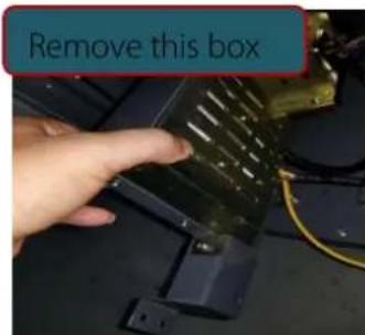
Fig. 2-24
natural_image
Close-up of an electrical circuit breaker with visible wiring and components (no text or symbols)Fig. 2-25
Note: Connect the wires in the original positions. Otherwise, more serious faults may be caused!
2.9 Replacement of Roller Motor
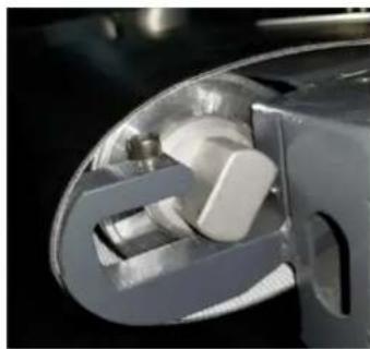
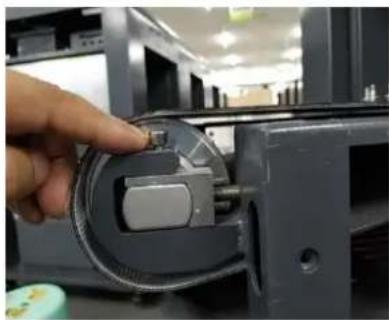
First remove the roller motor wire (remove the motor wire of the DC roller from the roller controller) (Fig. 2-26). Then remove two conveyor covers on the motor side (remote the dust caps of screw holes first and then the covers) (Fig. 2-27). Remove the conveyor guard (Fig. 2-28) and supporting roller assembly (Fig. 2-29), loosen the belt and remove the screws (Fig. 2-30) and motor (Fig. 2-31). Install a new motor according to the opposite steps. (Note: Do not damage the belt while removing the motor!)
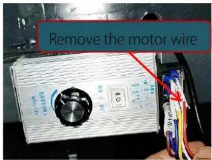
Fig. 2-26
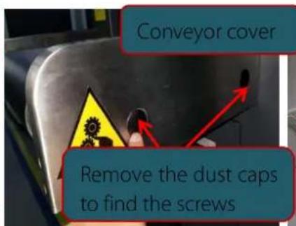
Fig. 2-27
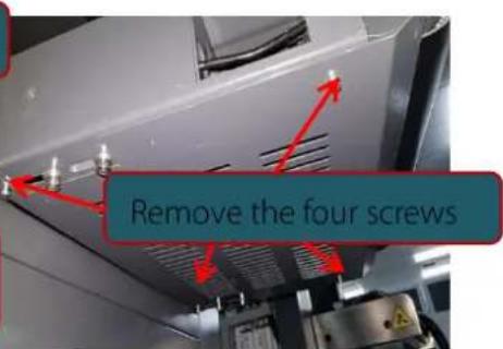
Fig. 2-28
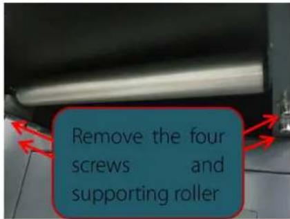
Fig. 2-29
natural_image
Close-up of a mechanical component with internal cavities and a metallic shaft (no visible text or symbols)Fig. 2-30
natural_image
Close-up of a hand inserting a small component into a device casing (no visible text or symbols)Fig. 2-31
2.10 Replacement of Driven Roller
Refer to the motor replacement steps. Compared with the roller motor, the motor wire is not involved in the driven roller.
2.11 Replacement of Supporting Roller
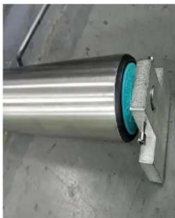
Remove the conveyor guard (Fig. 2-28) on the supporting roller side. Then remove the supporting roller assembly (Fig. 2-29 and 2-32) and the supporting roller. Install a new roller according to the opposite steps.
natural_image
Close-up of a metallic cylindrical mechanical component with a blue circular component inserted, mounted on a metal frame (no visible text or symbols)Fig. 2-32
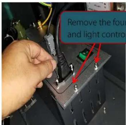
Fig. 2-33
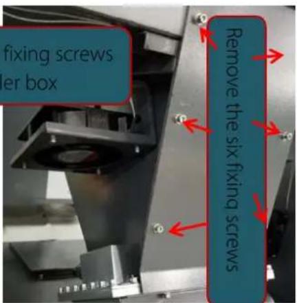
Fig. 2-34
2.12 Replacement of X-ray Generator
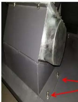
The X-ray generator is normally composed of two parts: "Ray Generator Control Box" and "Light Source", which should be replaced at the same time. (They are adjusted at the same time during ray generator production. The significant fault will occur probably or the service life of the ray generator will be shortened if only one part is replaced!) Remove all connecting wires of the "Light Source" and "Ray Generator Control Box", the fixing screws (Fig. 2-33) of "Ray Generator Control Box" and the "Ray Generator Control Box". Then remove the leak-proof lead guard (Fig. 2-34) of the "Light Source", the fixing screws (Fig. 2-35) of the base of the "Light Source", and finally the "Light Source", base and first collimating slit. Install a new X-ray generator according to the opposite steps.
2.13 Replacement of Lead Curtain
The lead curtain is used for shielding X-rays (Fig. 2-36). Open the top plate, and remove the fixing screws (Fig. 2-37) and then the whole lead curtain. Install a new lead curtain according to the opposite steps.
natural_image
Close-up of a metallic industrial component with red arrows pointing to features (no visible text or symbols)Fig. 2-35

Fig. 2-36
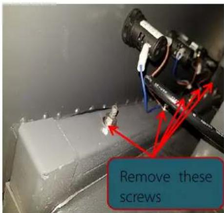
Fig. 2-37
2.14 Replacement of Conveyor Belt
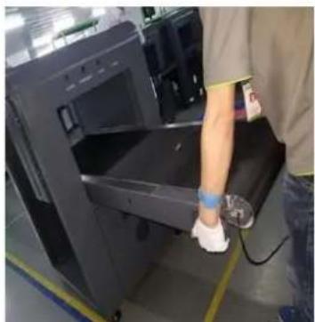
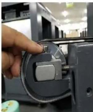
First, move four conveyor belt covers (Fig. 2-38), two conveyor guards (Fig. 2-39) and four fixing screws (Fig. 2-40). Then remove the motor wire and take out the conveyor (Fig. 2-41). Turn the conveyor upside down, and remove the two supporting roller assemblies (Fig. 2-42), two (iron-coated lead) small plates (Fig. 2-42), motor or driven roller and conveyor belt (Fig. 2-43) sequentially. Install a new conveyor belt according to the opposite steps. (Note: Do not damage the new conveyor belt during installation! Connect the motor wire properly. Otherwise, more serious faults may be caused!)
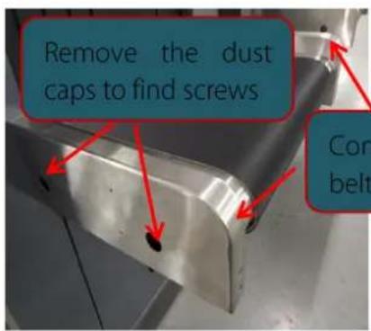
Fig. 2-38
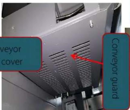
Fig. 2-39
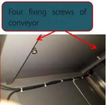
Fig. 2-40
natural_image
Person wearing a blue cap and gloves handling a large black electronic device (no visible text or symbols)Fig. 2-41
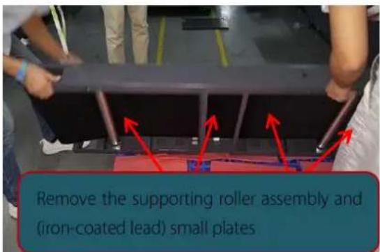
Fig. 2-42
natural_image
Close-up of a hand inserting a small component into a device casing (no visible text or symbols)Fig. 2-43
- Control Board PCBA, X-ray Generator LED Indicator and Interface
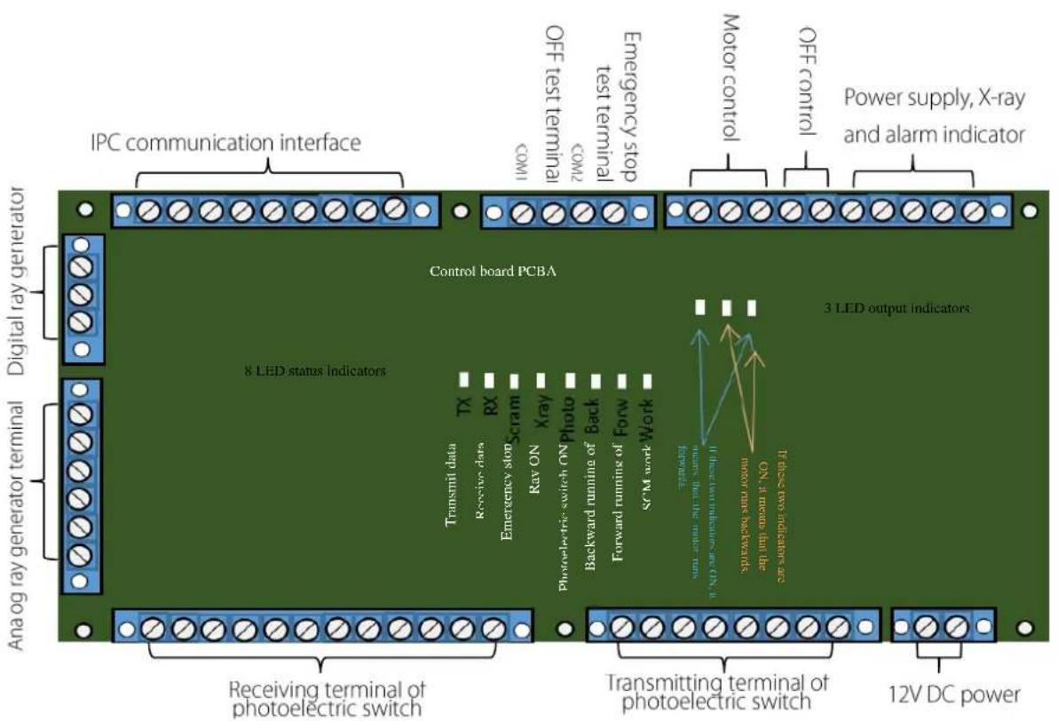
3.1 Interface of Control Board PCBA
3.2 LED Indicator and Interface of X-ray Generator
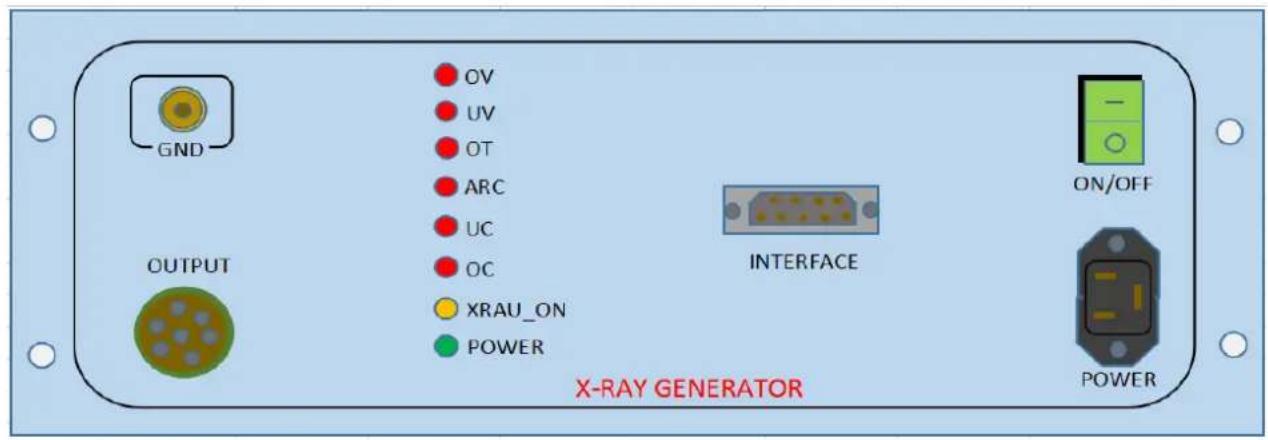
Description of letters on the control box indicators:
POWER: If this indicator is ON, it means that the X-ray generator is powered on.
XRAU_ON: If this indicator is ON, it means that the rays of X-ray generator are enabled (the slight brightness indicates the standby status).
OC: If this indicator is ON, it means that the X-ray generator is subject to overcurrent (the current at the tube end is too high).
UC: If this indicator is ON, it means that the X-ray generator is subject to undercurrent (the current at the tube end is too low).
ARC: If this indicator is ON, it means that serious sparking occurs in the X-ray generator.
OT: If this indicator is ON, it means that the X-ray generator is overheated (the light source is too hot).
UV: If this indicator is ON, it means that the X-ray generator is subject to under-voltage (the voltage at the tube end is too low).
OV: If this indicator is ON, it means that the X-ray generator is subject to over-voltage (the voltage at the tube end is too high).
Description of panel ports:
GND: Grounding terminal of the X-ray generator.
OUTPUT: Aviation plug between the X-ray generator and its control box.
INTERFACE: DB9 (RS232) socket of the X-ray generator controller connected to the control board PCBA.
ON/OFF: Power switch of the X-ray generator.
POWER: Power outlet of the X-ray generator.
4. Interpretation of Electrical Diagram
4.1 Interpretation of Electrical Diagram
flowchart
graph TD
    L --> DF
    N --> PE
    PE --> FU
    FU --> L"
    L" --> N"
    L --> K1
    L" --> K3
    L" --> K7
    L --> K6
    L --> K2
    L --> K7
    L --> SBE1
    L --> SBE2
    L --> SQ1
    L --> SQ2
    L --> SP
    L --> K3
    L --> K2
    L --> GND
    L --> +12V
    L --> DC
    L --> PW1
    PW1 --> AC
    AC --> DC
    AC --> GND
    SBE1 --> SK
    SBE2 --> SK
    SQ1 --> SK
    SQ2 --> SK
    SP --> SK
    +12V --> GND
    +12V --> GND
    +12V --> GND
    +12V --> GND
    +12V --> GND
    +12V --> GND
    +12V --> GND
    +12V --> GND
    +12V --> GND
    +12V --> GND
    +12V --> GND
    +12V --> GND
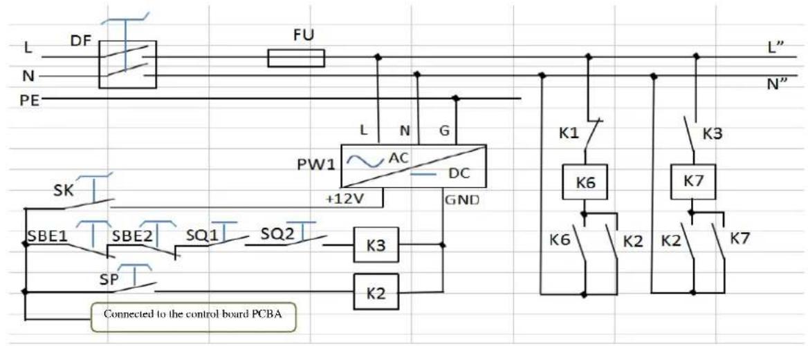
DF in this figure is the air switch, which will strip for protection in the case of overcurrent or short circuit. FU is the fuse, which is located in the same protective circuit as the air switch and used for dual protection. PW1 is the power supply, which is used for supplying the DC 12V power. If the key switch SK is in the ON position, the emergency stop buttons SBE1 and SBE2 are not pressed and the micro switches SQ1 and SQ2 are against the tightened doors, K3 will be closed. If the start button SP is pressed, K2 will be
closed, resulting in closing of the contactor K6. The normally contact of K6 is used for self-protection. Once K1 is not closed, K6 will keep the self-protection. Thus, the startup is completed.
If K3 and K2 are closed, K7 will be closed for self-protection. Once K3 is not disconnected, K7 will keep self-protection.
If the key switch SK is in the OFF position, the positive level will be changed into the negative level signal, which will be transmitted to the control board PCBA for shutdown. Then the shutdown with delay will be finished by the control board PCBA. If IPC is normally shut down (with delay), K1 will be closed for a short time, controlled by the control board PCBA. Thus, the equipment will be shut down. As shown in the figure, K7 is indirectly controlled by the emergency stop buttons SBE1 and SBE2 and micro switches SQ1 and SQ2 through K3.
flowchart
graph TD
    A["L" K6"] --> B["Control board PCBA"]
    C["N" K6"] --> B
    D["PE"] --> B
    B --> E["PW2 AC DC"]
    E --> F["+12V"]
    F --> G["K7"]
    G --> H["PE"]
    B --> I["K7"]
    I --> J["IPC"]
    I --> K["Display"]
    I --> L["DC power of detection board and transmission board"]
    L --> M["X-ray generator"]
    L --> N["Roller motor circuit"]
    L --> O["Cooling fan"]
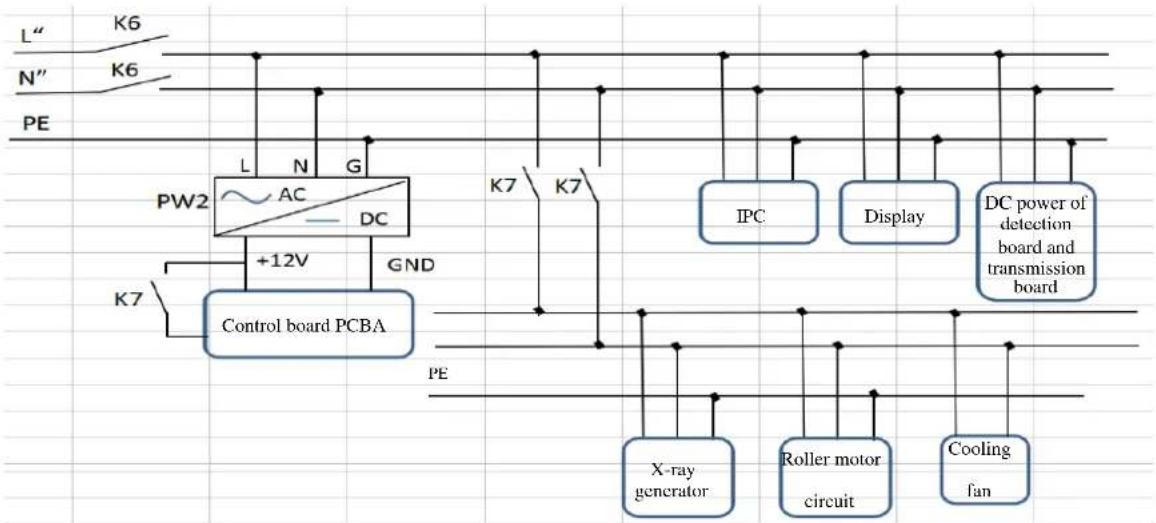
If K6 is closed, its two normally contacts will be connected to connect another switching power supply PW2, thus powering on the control board PCBA, display, IPC and detection/transmission board switch.
If K7 is closed, the X-ray generator, roller motor control circuit and cooling fan will be powered on. Thus, all the electrical appliances are powered on!
As K7 is indirectly controlled by the emergency stop buttons SBE1 and SBE2 and micro switches SQ1 and SQ2, the X-ray generator, roller motor circuit and cooling fan are also indirectly controlled by the emergency stop buttons SBE1 and SBE2 and micro switches SQ1 and SQ2. One normally open contact of K7 can be connected between the +12V power supply and control board PCBA, as an action signal for testing of the emergency stop buttons and micro switches.
flowchart
graph TD
    A["PE"] --> B["AC"]
    B --> C["DC"]
    C --> D["+48V"]
    D --> E["DC roller controller"]
    E --> F["EM"]
    G["K4"] --> H["Motor"]
    I["K5"] --> J["Motor"]
    H --> K["Roller motor circuit"]
    J --> K
    E --> L["PE"]
    E --> M["EM"]
Fig. 4-1
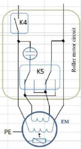
Fig. 4-2
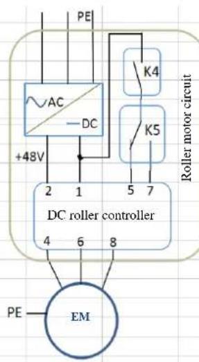
Two kinds of roller motor circuit are available. Normally, the circuit shown in Fig. 4-1 is applicable to the model 5030, where the DC roller motor controller is provided in the 48V DC switching power supply, the startup of the motor EM is controlled by the relay K4 and the forward/back running by the relay K5. The circuit in Fig. 4-2 is applicable to other models, in which only one capacitor is used, the startup of the motor EM is controlled by the relay K4 and the forward/back running by the relay K5.
flowchart
graph TD
    A["Detection board"] --> B["Transmission board"]
    C["Detection board"] --> D["Control board PCBA"]
    E["Detection board"] --> D
    B --> F["LAN"]
    D --> F
    F --> G["IPC"]
    G --> H["RS422"]
    G --> I["RS232"]
    I --> J["Special keyboard"]
    I --> K["Display"]
    L["RS232 X-ray generator"] <--> M["K1 K4 K5"]
    N["Photoelectric B switch B"] <--> O["×"]
    P["Photoelectric"] <--> Q["×"]
    R["VRGA AVI"] --> G
    S["USB USB USB"] --> I
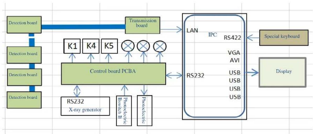
In this figure, the control board PCBA is used for controlling the relays K1, K4 and K5, power indicator, X-ray indicator, alarm indicator, and controlling and receiving the feedback information of the X-ray generator. It is also used for controlling "Photoelectric A", receiving the information of "Photoelectric B", and transmitting information to the upper computer (IPC) through the RS232 interface.
IPC is equipped with rich interfaces, including the RS232 interface connected to the control board, interface for the special keyboard (optional) and RS422 interface. It is able to receive the detection information from the "Detection Board" (bag inspection image sensor) through the "Transmission Board" and LAN port. Such information will be processed into images, which will be shown on the display connected through the VGA or AVI interface.
5. Maintenance
5.1 Dust Removal
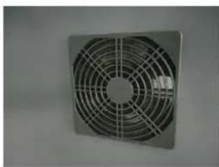
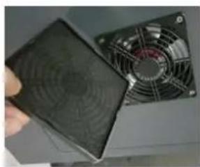
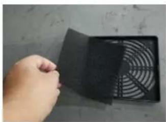
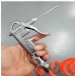
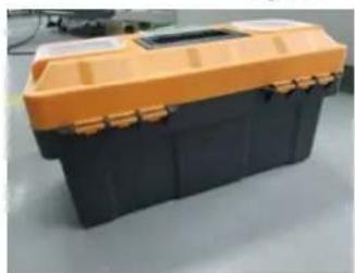
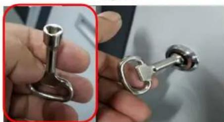
Preferably, the dust on the equipment surface should be cleaned once a day by wiping with soft cloth (Fig. 5-1), in order to keep the equipment always clean. The power supply should be cut off before wiping, to ensure the safety! Maintenance should be carried out promptly after some time to ensure long-term normal operation. Dust is produced inside the equipment after operation for some time. It is recommended to clean the inside once every six months, and replace the dust screen of the fan by removing it by hand (Fig. 5-2, 5-3 and 5-4) and installing a new one. (The cleaning interval can be adjusted, depending on the site environment). Dust should be purged with the "blower gun" (Fig. 5-5) or "electric blower gun". The triangular key and tool kit required for removal of the equipment cover are, free of charge, included in the standard configuration (Fig. 5-6 and 5-7).
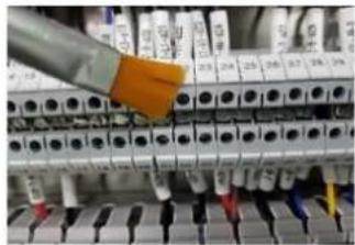
Before the "blower gun" is used, an appropriate "steam-water separation" device should be provided in the air pipe, to prevent water drops. The circuit boards and terminals should be wiped with a clean soft brush (Fig. 5-8) before purging with the "blower gun". The photoelectric switch hole should also be cleaned, to ensure the smoothness of the infrared ray path (Fig. 5-9). Priority should be given to the safety. That is, the power supply must be cut off before internal cleaning.
Equipment Maintenance Schedule:
| 1 | Overall cleaning | Twice a year |
| 2 | Cleaning of photoelectric switch and through hole | Twice a year |
| 3 | Replacement of dust screen of cooling fan | Twice a year |
| 4 | Replacement of cooling fan | Once per 10000h |
| 5 | Fastening of equipment screws | Once a year |
| 6 | Replacement of lead curtain | Once per 10000h |
| 7 | Replacement of conveyor belt | Once per 20000h |
| 8 | Replacement of supporting roller | Once per 20000h |
| 9 | Replacement of driven roller | Once per 20000h |
| 10 | Replacement of roller motor | Once per 30000h |
| 11 | Replacement of X-ray generator | Once per 30000h |
| 12 | Replacement of IPC mother board | Once per 20000h |
| 13 | Replacement of IPC hard disk | Once per 30000h |
| 14 | Replacement of contactor | Once per 30000h |
| 15 | Replacement of relay | Once per 30000h |
| 16 | Replacement of switching power supply | Once per 30000h |
| 17 | Replacement of air switch | Once per 30000h |
| 18 | Replacement of detection board/transmission board | Once per 30000h |
| 19 | Replacement of photoelectric switch | Once per 20000h |
| 20 | Replacement of indicator | Once per 30000h |
| 21 | Replacement of emergency stop and stop button | Once per 30000h |

natural_image
Folded white fabric on a green background (no text or symbols visible)Fig. 5-1
natural_image
Metal fan with radial mesh pattern, no visible text or symbolsFig. 5-2
natural_image
Close-up of a hand holding a black plastic fan next to a computer monitor fan (no visible text or symbols)Fig. 5-3
natural_image
Hand holding a black plastic fan with a circular grille, placed on a surface (no text or symbols visible)Fig. 5-4
natural_image
Close-up of a hand holding a metallic measuring tool with orange tape nearby (no visible text or symbols)Fig. 5-5
natural_image
Black and orange portable tool kit with handlebars (no visible text or symbols)Fig. 5-6
natural_image
Close-up of a hand holding two metallic key holders (no text or symbols visible)Fig. 5-7
natural_image
Close-up of electrical terminal blocks with a hand operating a component (no visible text or symbols)Fig. 5-8
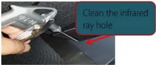
Fig. 5-9
5.2 Component Replacement
Two kinds of fan are applied in the equipment. Preferably, the five fans in total, including two chassis-mounted fans for cooling the whole equipment, one fan for cooling IPC and two fans for cooling the X-ray generator, should be replaced at the same time. Three DC 12V output terminals are provided on the switching power supply, Q12 for the weak-current control circuit, W12 for the special control board and V12 for the detection board and transmission board. IPC is equipped with one power adapter. The model 5030 is normally provided with one switching power supply for DC 48V output, which should be replaced at the same time. It is recommended to replace the five relays and two contactors respectively at the same time. The detection board and transmission board should be replaced by our technicians. The recommended periods of component replacement are listed in the "Equipment Maintenance Schedule" and the replacement steps of general components are described in "Component Replacement", with corresponding pictures. The power supply must be cut off before component replacement, in order to ensure the safety!
- Maintenance Manual
- Contents
- Simple Faults and Troubleshooting
- Failure of Startup after Powering-on
- Red "Emergency" in Lower Right Corner of LCD (Computer Display) and Failure of Roller Motor (Fig. 1-4)
- No Image of "Inspected Bag" during Normal Operation
- Red "System Error" in the Lower Right Corner of LCD (Computer Display) after Startup
- Failure of AC Roller Motor (if any) of Belt during Normal Operation
- Component Replacement
- Relay Replacement
- Contactor Replacement
- Replacement of Roller Motor Controller (for 5030)
- Fuse Replacement
- Replacement of Emergency Stop Button
- Indicator Replacement
- Replacement of Key Switch and Start Button
- Replacement of Air Switch
- Replacement of Roller Motor
- Replacement of Driven Roller
- Replacement of Supporting Roller
- Replacement of X-ray Generator
- Replacement of Lead Curtain
- Replacement of Conveyor Belt
- LED Indicator and Interface of X-ray Generator
- Description of letters on the control box indicators:
- Description of panel ports:
- Interpretation of Electrical Diagram
- Interpretation of Electrical Diagram
- Maintenance
- Dust Removal
- Component Replacement
Brand : ZKTeco
Model : ZKX6550V
Category : Security Camera