GMV-ND24TS/A-T(U) - Air Conditioning GREE - Free user manual and instructions
Find the device manual for free GMV-ND24TS/A-T(U) GREE in PDF.

| Product Type | Ducted Air Conditioner |
| Model | GMV-ND24TS/A-T(U) |
| Brand | Gree |
| Cooling Capacity | 24,000 BTU/h (7.03 kW) |
| Heating Capacity | 27,000 BTU/h (7.91 kW) |
| Power Supply | 208-230V / 60Hz / 1 Phase |
| Rated Cooling Power Input | 2.2 kW |
| Rated Heating Power Input | 2.3 kW |
| SEER Rating | 16.0 |
| HSPF Rating | 9.5 |
| Indoor Unit Dimensions (WxHxD) | 1120 x 260 x 500 mm |
| Indoor Unit Weight | 28 kg |
| Outdoor Unit Dimensions (WxHxD) | 920 x 710 x 420 mm |
| Outdoor Unit Weight | 52 kg |
| Refrigerant Type | R410A |
| Refrigerant Charge | 2.8 kg |
| Main Functions | Cooling, Heating, Dehumidification, Fan, Auto, Sleep, Turbo |
| Airflow Rate (High) | 1000 m³/h |
| Noise Level (Indoor) | 28-42 dB(A) |
| Noise Level (Outdoor) | 56 dB(A) |
| Maintenance | Clean air filters every 2 weeks; professional inspection annually |
| Safety Features | Overload protection, refrigerant leak detection, auto restart |
| Spare Parts | Remote control, air filters, drain hose, mounting brackets |
| Reparability | Modular design; main board, compressor, fan motor replaceable |
Frequently Asked Questions - GMV-ND24TS/A-T(U) GREE
User questions about GMV-ND24TS/A-T(U) GREE
0 question about this device. Answer the ones you know or ask your own.
Ask a new question about this device
Download the instructions for your Air Conditioning in PDF format for free! Find your manual GMV-ND24TS/A-T(U) - GREE and take your electronic device back in hand. On this page are published all the documents necessary for the use of your device. GMV-ND24TS/A-T(U) by GREE.
USER MANUAL GMV-ND24TS/A-T(U) GREE
Original Instructions
Commercial Air Conditioners
Multi Variable Air Conditioners Two-way Cassette Type Indoor Unit
Models:
GMV-ND09TS/A-T(U)
GMV-ND12TS/A-T(U)
GMV-ND15TS/A-T(U)
GMV-ND18TS/A-T(U)
GMV-ND24TS/A-T(U)
Thank you for choosing commercial air conditioners. Please read this Owner's Manual carefully before operation and retain it for future reference.
If you have lost the Owner's Manual, please contact the local agent or visit www.gree.com or send an email to global@gree.com.cn for the electronic version.
GREE ELECTRIC APPLIANCES, INC. OF ZHUHAI
Preface
For correct installation and operation, please read all instructions carefully. Before reading the instructions, please be aware of the following items:
 | This is the safety alert symbol. It is used to alert you to potential personal injury hazards. Obey all safety messages that follow this symbol to avoid possible injury or death. |
 WARNING WARNING | This mark indicates procedures which, if improperly performed, might lead to the death or serious injury of the user. |
 CAUTION CAUTION | This mark indicates procedures which, if improperly performed, might possibly result in personal harm to the user, or damage to property. |
 | NOTICE is used to address practices not related to personal injury. |

WARNING
| (1) Instructions for installation and use of this product are provided by the manufacturer. |
| (2) Installation must be performed in accordance with the requirements of NEC and CEC by authorized personnel only. |
| (3) For the safe operation of this unit, please read and follow the instructions carefully. |
| (4) During operation, total capacity of indoor units should not exceed the total capacity of outdoor units. Otherwise, poor effect of cooling or heating may result. |
| (5) Direct operators or maintainers should well keep this manual. |
| (6) If this unit fails to operate normally, please contact our service center as soon as possible and provide the following information:1) Content on the nameplate (model number, cooling capacity, production code, ex-factory date.2) Malfunction details (before and after the malfunction occurs. |
| (7) Each unit has been strictly tested and proved to be qualified before ex-factory. In order to prevent units from being damaged or operating normally because of improper disassembly, please do not disassemble the unit by yourself. If you need to disassemble and check units, please contact our service center. We will send specialists to guide the disassembly. |
| (8) Under the standbystatus, the unit will consume a little power for ensuring reliability of complete unit, maintaining normal communication and preheating refrigerant. When the unit won't be used for a long time, cut off the power of the complete unit. However, please preheat it when operating the unit next time. |
| (9) All graphics in this manual is only for your reference. For sales or production reasons, these graphics are subject to change by manufacturer without prior notice. |
| (10) These instructions shall also be available in an alternative format, e.g. on a website. |
User Notice
- This appliance can be used by children aged from 8 years and above and persons with reduced physical, sensory or mental capabilities or lack of experience and knowledge if they have been given supervision or instruction concerning use of the appliance in a safe way and understand the hazards involved. Children shall not play with the appliance. Cleaning and user maintenance shall not be made by children without supervision.
- DISPOSAL: Do not dispose this product as unsorted municipal waste. Collection of such waste separately for special treatment is necessary.
| Exception Clauses |
| Manufacturer will bear no responsibilities when personal injury or property loss is caused by the following reasons: |
| (1) Damage the product due to improper use or misuse of the product; |
| (2) Alter, change, maintain or use the product with other equipment without abiding by the instruction manual of manufacturer; |
| (3) After verification, the defect of product is directly caused by corrosive gas; |
| (4) After verification, defects are due to improper operation during transportation of product; |
| (5) Operate, repair, maintain the unit without abiding by instruction manual or related regulations; |
| (6) After verification, the problem or dispute is caused by the quality specification or performance of parts and components that produced by other manufacturers; |
| (7) The damage is caused by natural calamities, bad using environment or force majeure. |
Contents
1 Safety Precautions.... 1
2 Product Introduction 2
2.1 Names of Key Components 2
2.2 Rated Working Condition 2
3 Preparations for Installation 2
3.1 Standard Fittings 2
3.2 Installation Position Selection 3
3.3 Requirements of communication wire selection 4
3.4 Wiring Requirements 6
4 Installation Instructions 6
4.1 Installation of Indoor Unit 6
4.2 Refrigerant Pipe Connection 8
4.3 Drainage Pipe Installation and Drainage System Testing 9
4.4 Panel installation.... 12
4.5 Installation of Wired Controller 13
5 Wiring Work 14
5.1 Connection of Wire and Patch Board Terminal 14
5.2 Power Cord Connection....15
5.3 Connection of Communication Wire between Indoor Unit and Outdoor Unit (or indoor unit) 15
5.4 Connection of Communication Wire for Wired Controller 16
5.5 Wiring Instructions of Wired Controller and Indoor Units Network ..... 16
6 Routine Maintenance....18
6.1 Cleaning of Filter 18
6.2 Maintenance before the Seasonal Use.... 18
6.3 Maintenance after the Seasonal Use 18
7 Table of Error Codes for Indoor Unit 19
8 Display of Light Board....19
9 Troubleshooting 20
1 Safety Precautions
| WARNING |
| (1) This product can't be installed at corrosive, inflammable or explosive environment or the place with special requirements, such as kitchen. Otherwise, it will affect the normal operation or shorten the service life of the unit, or even cause fire hazard or serious injury. As for above special places, please adopt special air conditioner with anti-corrosive or anti-explosion function. |
| (2) Follow this instruction to complete the installation work. Please carefully read this manual before unit startup and service. |
| (3) Wire size of power cord should be large enough. The damaged power cord and connection wire should be replaced by exclusive cable. |
| (4) After connecting the power cord, please fix the electric box cover properly in order to avoid accident. |
| (5) Never fail to comply with the nitrogen charge requirements. Charge nitrogen when welding pipes. |
| (6) Never short-circiut or cancel the pressure switch to prevent unit damage. |
| (7) Please firstly connect the wired controller before energization, otherwise wired controller can not be used. |
| (8) Before using the unit, please check if the piping and wiring are correct to avoid water leakage, refrigerant leakage, electric shock, or fire etc. |
| (9) Do not insert fingers or objects into air outlet/inlet grille. |
| (10) Open the door and window and keep good ventilation in the room to avoid oxygen deficit when the gas/oil supplied heating equipment is used. |
| (11) Never start up or shut off the air conditioner by means of directly plug or unplug the power cord. |
| (12) Turn off the unit after it runs at least five minutes; otherwise it will influence oil return of the compressor. |
| (13) Do not allow children operate this unit. |
| (14) Do not operate this unit with wet hands. |
| (15) Turn off the unit or cut off the power supply before cleaning the unit, otherwise electric shock or injury may happen. |
| (16) Never spray or flush water towards unit, otherwise malfunction or electric shock may happen. |
| (17) Do not expose the unit to the moist or corrosive circumstances. |
| (18) Under cooling mode, please don't set the room temperature too low and keep the temperature difference between indoor and outdoor unit within 5°C (41°F). |
| (19) User is not allowed to repair the unit. Fault service may cause electric shock or fire accidents. Please contact Gree appointed service center for help. |
| (20) Before installation, please check if the power supply is in accordance with the requirements specified on the nameplate. And also take care of the power safety. |
| (21) Installation should be conducted by dealer or qualified personnel. Please do not attempt to install the unit by yourself. Improper handling may result in water leakage, electric shock or fire disaster etc.. |
| (22) Be sure to use the exclusive accessory and part to prevent the water leakage, electric shock and fire accidents. |
| (23) Make sure the unit can be earthed properly and soundly after plugging into the socket so as to avoid electric shock. Please do not connect the ground wire to gas pipe, water pipe, lightning rod or telephone line. |
| (24) Electrify the unit 8 hours before operation. Please switch on for 8 hours before operation. Do not cut off the power when 24 hours short-time halting (to protect the compressor). |
| (25) If refrigerant leakage happens during installation, please ventilate immediately. Poisonous gas will emerge if the refrigerant gas meets fire. |
| (26) Volatile liquid, such as diluent or gas will damage the unit appearance. Only use soft cloth with a little neutral detergent to clean the outer casing of unit. |
| (27) If anything abnormal happens (such as burning smell), please power off the unit and cut off the main power supply, and then immediately contact Gree appointed service center. If abnormality keeps going, the unit might be damaged and lead to electric shock or fire. |
Any personal injury or property loss caused by improper installation, improper debug, and unnecessary repair or not following the instructions of this manual should not be the responsibility of Gree Electric Appliances, Inc. of Zhuhai.
2 Product Introduction
2.1 Names of Key Components
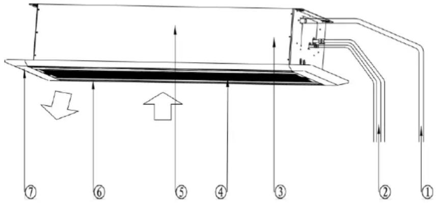
Fig. 2.1.1
| No. | 1 | 2 | 3 | 4 | 5 | 6 | 7 |
| Name | Drainage Pipe | Connection Pipe | Drainage Device | Air Inlet Grille (With Filter) | Main Unit | Louver | Panel |
2.2 Rated Working Condition
| Indoor Side Condition | Outdoor Side Condition | |||
| Dry Bulb Temp °C(°F) | Wet Bulb Temp °C(°F) | Dry Bulb Temp °C(°F) | Wet Bulb Temp °C(°F) | |
| Rated Cooling | 26.7(80.0) | 19.4(67.0) | 35(95.0) | 23.9(75.0) |
| Rated Heating | 21.1(70.0) | 15.6(60.0) | 8.3(47.0) | 6.1(43.0) |
3 Preparations for Installation
NOTICE!
Product graphics are only for reference. Please refer to actual products. Unspecified measure unit is mm (in.)
3.1 Standard Fittings
Use the following provided accessories according to the requirement.
| No. | Name | Appearance | Q'ty | Usage |
| 1 | Drainage hose assembly | 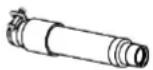 | 1 | To connect the drainage pipe |
| 2 | Special Nut |  | 2 | GMV-ND09~15TS/A-T(U) |
 | 1 | GMV-ND18~24TS/A-T(U) | ||
| 3 | corrugated pipe | 1 | GMV-ND18~24TS/A-T(U) | |
| 4 | Insulation |  | 1 | To insulate the gas pipe |
| 5 | Insulation |  | 1 | To insulate the liquid pipe |
| No. | Name | Appearance | Q'ty | Usage | |
| 6 | Sponge |  | 1 | To insulate the drain pipe | |
| 7 | Fastener | 4 | To fasten the sponge | ||
| 8 | paper pattern for installation | 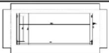 | 1 | Locate the drill hole on ceiling | |
| 9 | Tapping screw with washer |  | 4 | Fix paper pattern | |
| 10 | M10 Washer |  | 10 | To be used together with the hanger bolt for installing the unit | |
| 11 | Washer fixing plate | 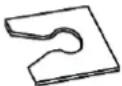 | 4 | Prevent the washer from falling off | |
| 12 | Remote controller | 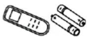 | 1+2 | To control the indoor unit | |
| 13 | Remote controller holder | 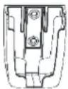 | 1 | Used for holding the remote controller | |
| 14 | Tapping screw |  | 2 | Used for fixing the remote controller holder | |
3.2 Installation Position Selection
(1) The appliance shall not be installed in the laundry.
(2) The top holder must be strong enough to support unit's weight.
(3) Drain pipe can drain water out easily.
(4) There is no obstacle at inlet or outlet. Please ensure good air circulation.
(5) In order to make sure the space for maintenance, please install the indoor unit according to the dimension described below.
(6) Keep the unit away from heating source, inflammable gas or smoke.
(7) This is a concealed ceiling type unit.
(8) Indoor unit, outdoor unit, power cord and electric wire should stay at least 1m (39-3/8 in.) from the TV set and radio. Otherwise, these electrical appliances may have image interference and noise. (Even if the distance is 1m (39-3/8 in.), when there is strong electric wave, noise may still occur).
Unit: mm (in)
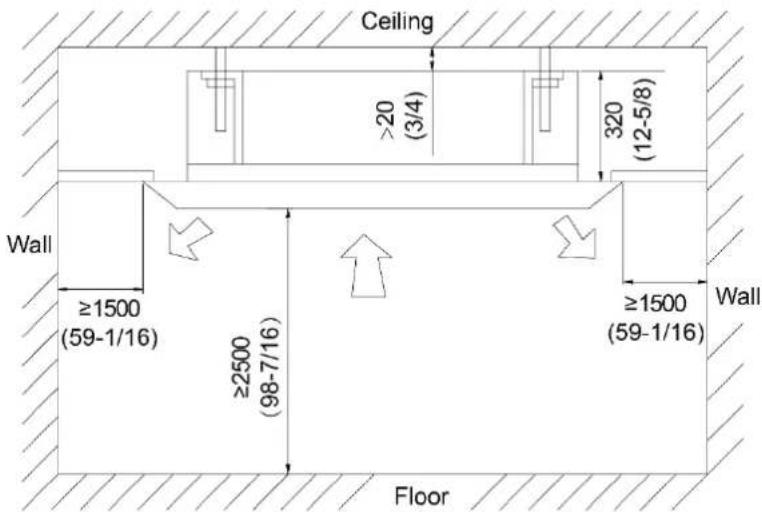
Fig. 3.2.1
| NOTICE |
| (1) The unit shall be installed in accordance with national standards or local regulations. |
| (2) Only qualified personnel can carry out installation work, please contact with local dealer before installation. |
| (3) Make sure all the installation work completed before energizing. |
3.3 Requirements of communication wire selection
NOTICE!
If the unit is installed in the place with strong electromagnetic interference, shielded wire must be applied on the communication wire between indoor unit and wired controller. Twisted pair line with shielding function must be applied on the communication wire between indoor unit and indoor unit (outdoor unit).
3.3.1 Selection of Communication Wire between Indoor Unit and Wired Controller
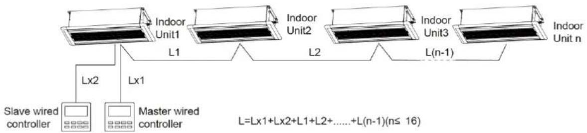
flowchart
graph TD
    A["Slave wired controller"] -->|Lx2| B["Indoor Unit1"]
    C["Master wired controller"] -->|Lx1| D["Indoor Unit2"]
    E["Indoor Unit3"] -->|L(n-1)| F["Indoor Unit n"]
    B -->|L1| D
    D -->|L2| F
    style A fill:#f9f,stroke:#333
    style C fill:#f9f,stroke:#333
    style E fill:#f9f,stroke:#333
Fig. 3.3.1
| Wire type | Total length of communication wire between indoor unit and wired controller (m/ft.) | Wire diameter (AWG) | Wire standard | Remark |
| Light/Ordinary polyvinyl chloride sheathed cord. (60227 IEC 52 /60227 IEC 53) | L≤250m(L≤820-1/5ft.) | 2×0.75~2×1.25(2× AWG18~2× AWG16) | IEC 60227-5 | 1. Total length of communication line can't exceed 250m (820-1/5ft.).2. The cord shall be Circular cord (the cores shall be twisted together).3. If unit is installed in places with intense magnetic field or strong interference, it is necessary to use shielded wire. |
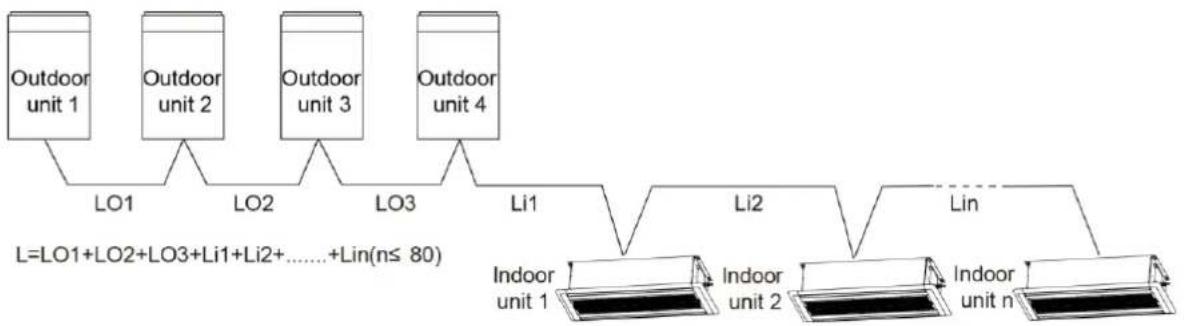
3.3.2 Selection of communication wire between indoor unit and indoor unit (or outdoor unit)
flowchart
graph TD
    A["Outdoor unit 1"] --> B["LO1"]
    C["Outdoor unit 2"] --> D["LO2"]
    E["Outdoor unit 3"] --> F["LO3"]
    G["Outdoor unit 4"] --> H["Li1"]
    I["Indoor unit 1"] --> J["Li2"]
    K["Indoor unit 2"] --> L["lin"]
    M["Indoor unit n"] --> N["lin"]
    style A fill:#f9f,stroke:#333
    style C fill:#f9f,stroke:#333
    style E fill:#f9f,stroke:#333
    style G fill:#f9f,stroke:#333
    style I fill:#ccf,stroke:#333
    style K fill:#ccf,stroke:#333
    style M fill:#ccf,stroke:#333
    style B fill:#dfd,stroke:#333
    style D fill:#dfd,stroke:#333
    style F fill:#dfd,stroke:#333
    style H fill:#dfd,stroke:#333
    style J fill:#dfd,stroke:#333
    style L fill:#dfd,stroke:#333
    note right of A: L=LO1+LO2+LO3+Li1+Li2+......+Lin(n≤80)
    end
Fig. 3.3.2
| Wire type | Total length of communication wire between indoor unit and indoor unit (outdoor unit) (m/ft.) | Wire diameter (AWG) | Wire standard | Remark |
| Light/Ordinary polyvinyl chloride sheathed cord. (60227 IEC 52 /60227 IEC 53) | L≤1000m(L≤3280-5/6ft.) | ≥2×0.75(≥2×AWG18) | IEC 60227-5 | 1. If the wire diameter is enlarged to 2×1 mm ^2 (2× AWG16), the total communication line length can reach 1500 m (4921-1/4ft.).2. The cord shall be Circular cord (the cores shall be twisted together).3. If unit is installed in places with intense magnetic field or strong interference, it is necessary to use shielded wire. |
3.4 Wiring Requirements
Power Cord Size and Air Switch Capacity
| Model | Power Supply | MCA(A) | MOP(A) |
| GMV-ND09TS/A-T(U) | 208/230V-1ph-60Hz | 1 | 15 |
| GMV-ND12TS/A-T(U) | 1 | 15 | |
| GMV-ND15TS/A-T(U) | 1 | 15 | |
| GMV-ND18TS/A-T(U) | 1 | 15 | |
| GMV-ND24TS/A-T(U) | 1 | 15 |
| NOTICE |
| (1) An all-pole disconnection switch having a contact separation of at least 3mm (1/8 in.) in all poles should be connected in fixed wiring. |
| (2) The circuit breaker and power cord specification in above sheet is based on max power (max current) of the unit. |
| (3) The power cord specification in above sheet is based on ambient temperature of 40(104° F). |
| (4) The circuit breaker specification in above sheet is based on ambient temperature of 40(104° F). If the working condition is different, please adjust it according to the specification sheet of circuit breaker. |
4 Installation Instructions
4.1 Installation of Indoor Unit
4.1.1 Ceiling opening Dimension and suspension bolt position.
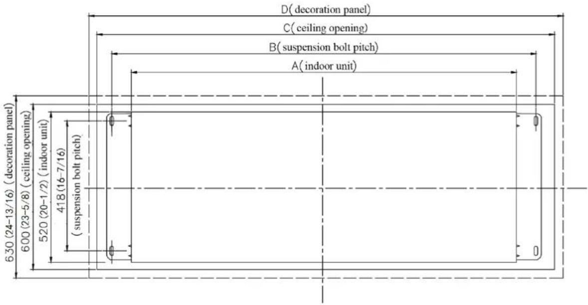
Fig. 4.1.1
Unit: mm(in.)
| Model | Indoor unit(A) | Suspension bolt pitch(B) | Ceiling opening(C) | Decoration panel(D) | Outer diameter of connection pipe(mm(in.)) | |
| Liquid pipe | Gas pipe | |||||
| GMV-ND09TS/A-T(U) | 1200(47-1/4) | 1252(49-5/16) | 1386(54-9/16) | 1416(55-3/4) | 6.35(1/4) | 9.52(3/8) |
| GMV-ND12TS/A-T(U) | 1200 | 1252 | 1386 | 1416 | 6.35 | 12.7 |
| GMV-ND15TS/A-T(U) | (47-1/4) | (49-5/16) | (54-9/16) | (55-3/4) | (1/4) | (1/2) |
| GMV-ND18TS/A-T(U) | 1200 | 1252 | 1386 | 1416 | 9.52 | 15.9 |
| GMV-ND24TS/A-T(U) | (47-1/4) | (49-5/16) | (54-9/16) | (55-3/4) | (3/8) | (5/8) |
4.1.2 Suspend the indoor unit
(1) Drill bolt holes and install bolts.
1) Stick the paper pattern on the installation position; drill 4 holes according to the hole site on the cardboard as shown in fig. 4.1.2; diameter of drilling hole is according to the diameter of expansion bolt and the depth is 60\~70 (2-1/3\~2-3/4) mm, as shown in fig. 4.1.3.
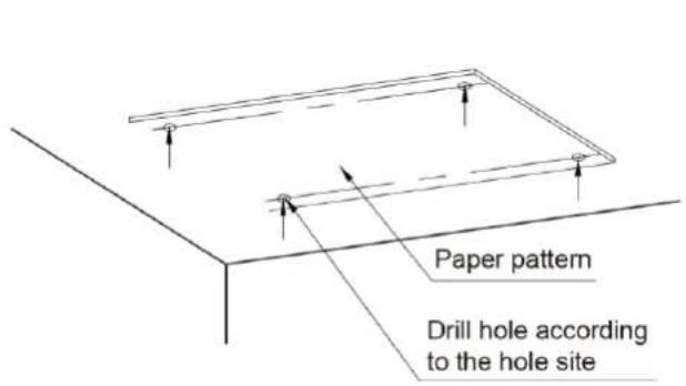
Fig. 4.1.2
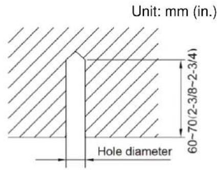
Fig. 4.1.3
2) Insert the M10 expansion bolt into the hole and then knock the nail into the bolt, as shown in fig. 4.1.4.
NOTICE!
The length of bolt depends on the installation height of the unit, bolts are field supplied.
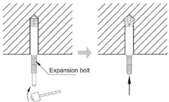
Fig. 4.1.4
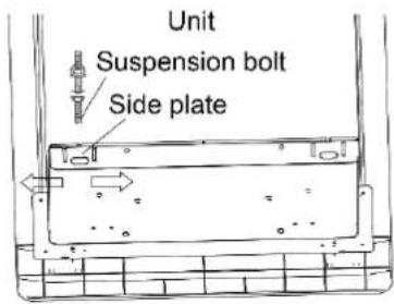
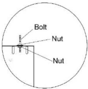
(2) Install the indoor unit temporarily.
Assemble suspension bolt on the expansion bolt, attach the hanger bracket to the suspension bolt. Be sure to fix it securely by using a nut and washer from upper and lower sides of the hanger bracket. The washer fixing plate will prevent the washer from falling.
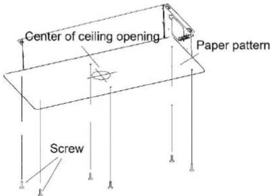
(3) The usage of paper pattern.
Refer to paper pattern of installation for ceiling opening dimension. The center of ceiling
opening is indicated on the paper pattern. Fix the paper pattern to the unit with 4 screws and fix the corners of the waterspout at the drainage pipe by screws.
(4) Adjust the unit to the right position.
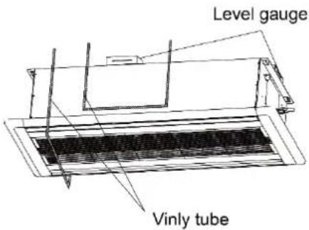
(5) Check the level of the unit.
The indoor unit is equipped with build-in water pump and float switch, verify the levelness of 4 directions by level gauge or vinyl tube (filled with water) respectively.
(6) Remove the washer locating plate and then tighten the nut on it.
(7) Remove the paper pattern.
Fix the hanger bracket firmly
Fix the washer firmly
Fix the hanger bracket firmly
Fix paper pattern
Fig. 4.1.5
4.2 Refrigerant Pipe Connection
(1) Aim the flaring port of copper pipe at the center of screwed joint and then tighten the flaring nut with hand as shown in fig. 4.2.1.
(2) Tighten the flaring nut with torque wrench.
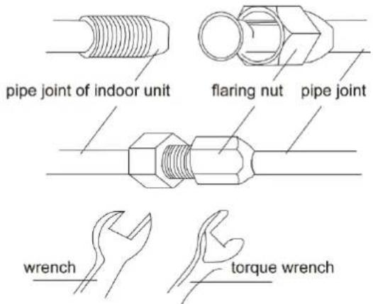
Fig.4.2.1
| Pipe diameter mm(in.) | Torque(N·m) |
| 6.35(1/4) | 15~30 |
| 9.52(3/8) | 35~40 |
| 12.7(1/2) | 45~50 |
| 15.9(5/8) | 60~65 |
(3) Use pipe bend when bending the pipe and the bending angle should not be too small.
(4) Wrap the connection pipe and joint with sponge and then tie them firmly with tape.
4.3 Drainage Pipe Installation and Drainage System Testing
4.3.1 Notice for Installation of Drainage Pipe
(1) It is not allowed to connect the condensate drain pipe into waste pipe or other pipelines which are likely to produce corrosive or peculiar smell to prevent the smell from entering indoors or corrupt the unit.
(2) It is not allowed to connect the condensate drain pipe into rain pipe to prevent rain water from pouring in and cause property loss or personal injury.
(3) Condensate drain pipe should be connected into special drain system for air conditioner.
(4) The drainage pipe should be short and the gradient downwards should be at least 1%\~2% in order to drain condensation water smoothly.
(5) The diameter of drainage hose should be bigger or equal to the diameter of drainage pipe joint.
(6) Install drainage pipe according to the following fig. and arrange insulation to the drainage pipe. Improper installation may lead to water leakage and damp the furniture and other things in the room.
(7) You can buy normal hard PVC pipe used as the drainage pipe. During connection, insert the end of PVC pipe into the drainage hole and then tighten it with drainage hole and wire binder. Can't connect the drainage hole and drainage hole with glue.
(8) When the drainage pipelines are used for several units, the position of pipeline should be about 100mm (4 in.) lower than the drainage port of each unit. In this case, thicker pipes should be applied.
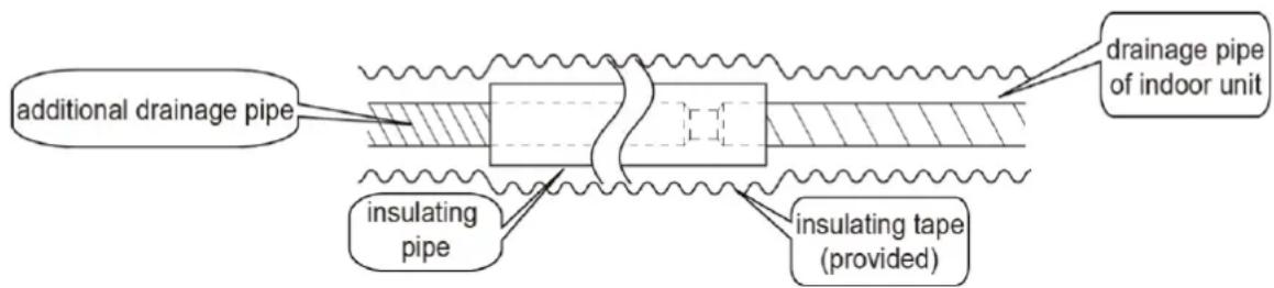
Fig. 4.3.1
4.3.2 Installation of Drainage pipe
(1) Drainage pipe should have the same diameter or larger diameter than the connection pipes (PVC pipe, outside diameter 25mm (1 in.), thickness≥1.5mm (1/16 in.)).
(2) Keep drainage pipe short and sloping downwards at a gradient of at least 1% for preventing forming air bubbles.
(3) If the gradient of drainage pipe could not meet the installation requirements, raising pipe should be applied.
(4) Insert the drainage hose into drain socket and then tighten the metal clamp securely.
(5) Warp the sealing pad over drainage hose and metal clamp for heat insulation.
(6) Make sure to perform insulation work for all drainage hoses in the room in order to prevent any possible water dropping due to dew condensation.
(7) Apply the suitable diameter for converging drainage pipe according to the operating capacity of the unit, as show in Fig. 4.3.2.
Unit: mm (in.)
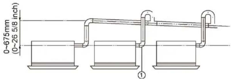
① - drainage pipes assembled by T-shaped joints
Fig. 4.3.2
(8) The installation height of raising pipe for drainage should be lower than B. The gradient from raising pipe towards drainage direction should be at least 1%\~2%. If the raising pipe is vertical with the unit, the raising height should be less than C.
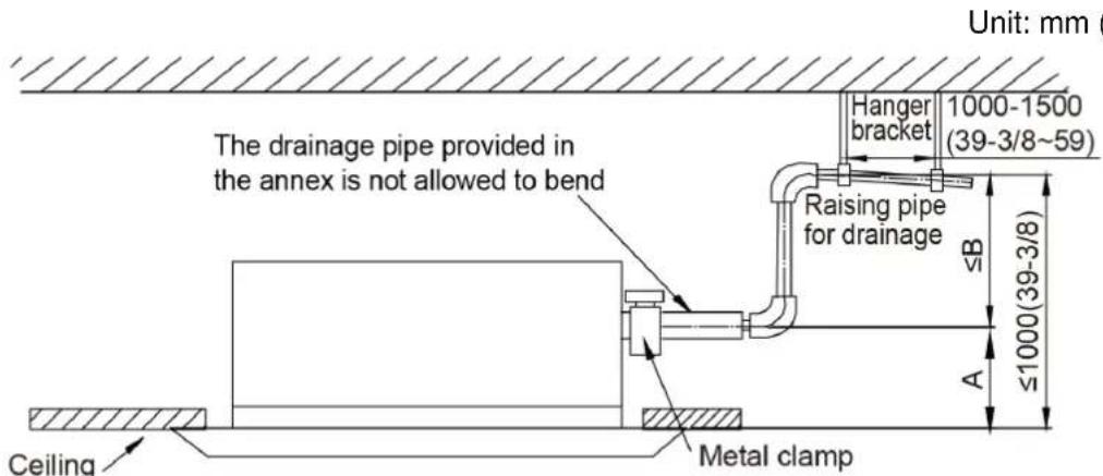
Fig. 4.3.3
| Model | A(mm(in.)) | B(mm(in.)) | C(mm(in.)) |
| GMV-ND09TS/A-T(U)GMV-ND12TS/A-T(U)GMV-ND15TS/A-T(U)GMV-ND18TS/A-T(U)GMV-ND24TS/A-T(U) | 260(11-3/4) | 740(30-7/8) | 690(27-3/16) |
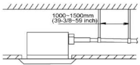
(9) Drainage pipes should have a downward slope of at least 1%\~2%, in order to prevent pipes from sagging; install hanger bracket at intervals of 1000\~1500mm (39-3/8\~59in.).
Unit: mm (in.)
√
natural_image
Pure technical line drawing of a mechanical assembly with no text or symbols×
Fig. 4.3.4
(10) During the installation, distance from soft drain pipe to the gasket is C ~mm when the bolt is tightened. It is not allowed to apply PVC or other related glue in the joints of two ends of drain pipe.
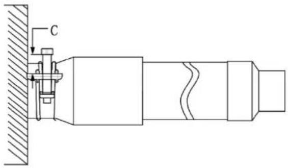
Fig. 4.3.5
| Model | C (mm/in.) |
| GMV-ND09TS/A-T(U)GMV-ND12TS/A-T(U)GMV-ND15TS/A-T(U)GMV-ND18TS/A-T(U)GMV-ND24TS/A-T(U) | 8~12(5/16~1/2) |
4.3.3 Test of Drainage System
(1) Please test drainage system after electric work is finished.
1) Inject approximately 1L purified water to drain pan from air vent, ensure that not to splash the water over the electrical components (e.g. water pump, etc).
2) In case of commissioning finished, please energize the IDUs and switch to cooling or dry mode, meanwhile, the water pump operates, you can check the draining through the drain socket.
3) If communication wire is not connected, communication malfunction "C0" will occur after 60s of energizing. In this case, the water pump operates automatically. Check if the water pump drains normally through drainage port. The water pump will stop automatically after running for 10mins.
(2) During the test, please carefully check the drainage joint, make sure no any leakage occur.
(3) It is strongly recommend to do the drain test before ceiling decoration.
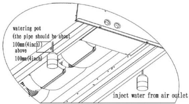
Fig. 4.3.6
4.4 Panel installation
4.4.1 Notices for installation
(1) Improper decorative panel installation could cause the following problems.
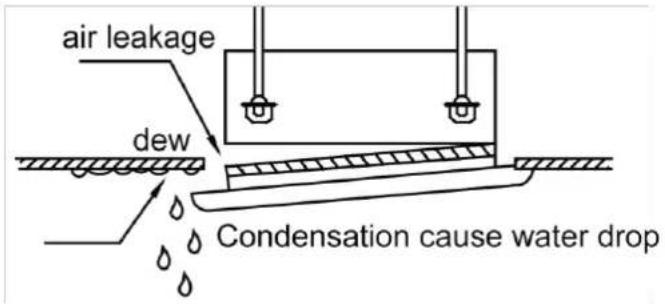
Fig. 4.4.1
(2) Ensure that its clearance-free between decoration panel and ceiling board after installation, if not, please adjust the body position.
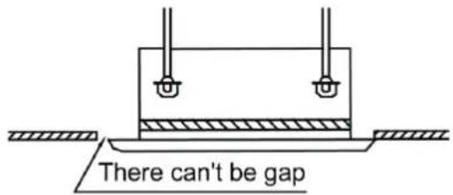
Fig. 4.4.2
(3) Connect the decoration panel terminals (Female) to body terminals (male) as shown in fig.4.4.3.
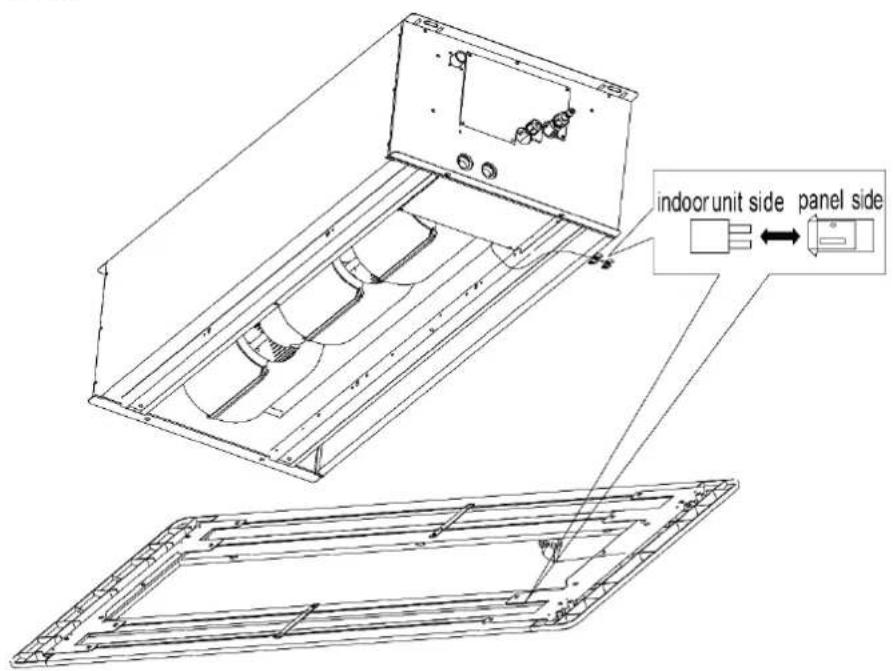
Fig. 4.4.3
4.4.2 Panel installation
(1) Adjust the panel direction. Let the swing motor on the panel keep the same side with connection pipe.
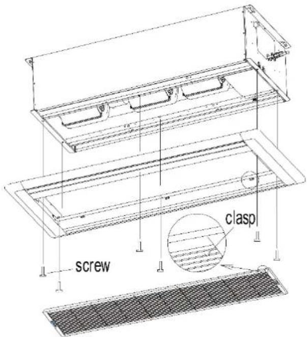
Fig. 4.4.4
(2) Adjust the position of panel to make the panel holes fix at the holes on the unit.
(3) Fix the 4 screws at the two side of panel and then fix the 2 screws in the middle of panel.
(4) Install the air inlet grille and then lock the clasp.
(5) Tighten the screw until the thickness of sealing material between panel and indoor unit is about 5\~8mm(3/16\~5/16in).
Unit: mm (in.)
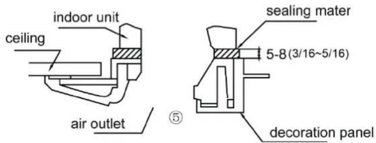
Fig. 4.4.5
4.5 Installation of Wired Controller
Please refer to User Manual of Wired Controller for the installation details.
NOTICE!
When installation is finished, the unit must be tested and debugged before operation. Please refer to Instruction Manual of ODU for auto addressing and debugging details.
5 Wiring Work
 WARNING WARNING |
| Before obtaining access to terminals, all supply circuits must be disconnected. |
| NOTICE |
| (1) Units must be earthed securely, or it may cause electric shock. |
| (2) Please carefully read the wiring diagram before carry out the wiring work, incorrect wiring could cause malfunction or even damage the unit. |
| (3) The unit should be powered by independent circuit and specific socket. |
| (4) The wiring should be in accordance with related regulations in order to ensure the units reliable running. |
| (5) Install circuit breaker for branch circuit according to related regulations and electrical standards. |
| (6) Keep cable away from refrigerant pipings, compressor and fan motor. |
| (7) The communication wires should be separated from power cord and connection wire between indoor unit |
| (8) Adjust the static pressure via wired controller according to site circumstance. |
5.1 Connection of Wire and Patch Board Terminal
(1) The connection of wire (as shown in fig. 5.1.1)
1) Strip about 25mm (1 in.) insulation of the wire end by stripping and cutting tool.
2) Remove the wiring screws on the terminal board.
3) Shape the tail of wire into ring by needle nose plier, and keep the gauge of ring in accordance with screw.
4) Use the screwdriver for tightening the terminal.
(2) The connection of stranded wire (as shown in fig. 5.1.2)
1) Strip about 10mm (3/8 in.) insulation of the end of stranded wire by stripping and cutting tool.
2) Loosen the wiring screws on terminal board.
3) Insert the wire into the ring tongue terminal and tighten by crimping tool.
4) Use the screwdriver for tightening the terminal.
Unit: mm (in.)
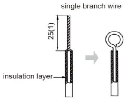
Fig. 5.1.1
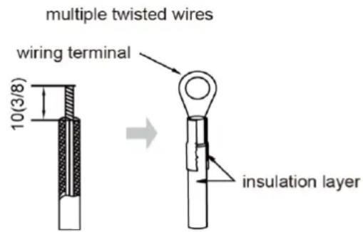
Fig. 5.1.2
5.2 Power Cord Connection
NOTICE!
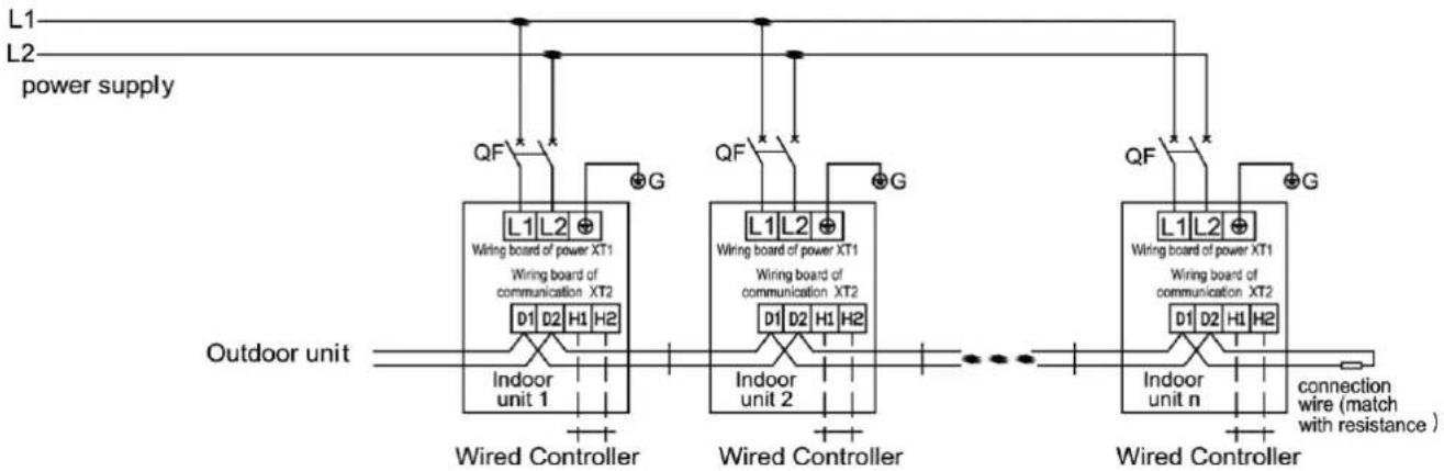
Every unit should be equipped with a circuit breaker for short-circuit and overload protection. During operation, all indoor units connected to the same outdoor unit system must be kept energized status. Otherwise, the unit can't operate normally.
flowchart
graph TD
    A["Outdoor unit"] --> B["Wired Controller"]
    B --> C["Indoor unit 1"]
    B --> D["Indoor unit 2"]
    B --> E["Indoor unit n"]
    C --> F["Wired Controller"]
    D --> G["Wired Controller"]
    E --> H["Wired Controller"]
    I["L1"] --> J["QF"]
    K["L2"] --> L["QF"]
    M["L1L2"] --> N["Wiring board of power XT1"]
    M --> O["Wiring board of communication XT2"]
    P["QF"] --> Q["G"]
    R["QF"] --> S["G"]
    T["QF"] --> U["G"]
    V["QF"] --> W["G"]
    X["QF"] --> XG[" connection wire (match with resistance )"]
    style A fill:#f9f,stroke:#333
    style K fill:#f9f,stroke:#333
    style I fill:#ccf,stroke:#333
    style L fill:#ccf,stroke:#333
    style M fill:#ccf,stroke:#333
    style Y fill:#ccf,stroke:#333
    style Z fill:#ccf,stroke:#333
Fig. 5.2.1
For units with single-phase power supply.
(1) Detach the electric box lid.
(2) Let the power cord pass through the wiring through-holes.
(3) Connect the power cord to terminal "L1, L2, ⚙"
(4) Fix the power card with wiring clamp.
(5) The wire diameter of power cord can't be less than 18AWG.
5.3 Connection of Communication Wire between Indoor Unit and Outdoor Unit (or indoor unit)
(1) Detach the electric box cover.
(2) Let the Communication cable pass through the wiring through-holes.
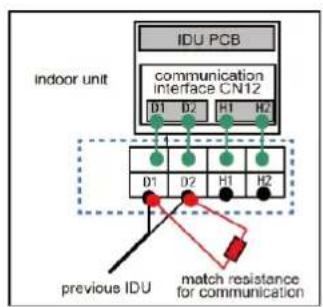
(3) Connect the communication wire to terminal D1 and D2 of indoor 4-bit wiring board, as shown in Fig.5.3.1.
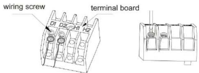
Fig. 5.3.1
flowchart
graph TD
    A["INDU PCB"] --> B["communication interface CN12"]
    B --> C["previous IDU"]
    C --> D["match resistance for communication"]
    style A fill:#f9f,stroke:#333
    style B fill:#ccf,stroke:#333
    style C fill:#cfc,stroke:#333
    style D fill:#fcc,stroke:#333
Fig. 5.3.2
(4) Fix the communication cable with clamp of electric box.
(5) For more reliable communication, make sure connect the terminal resistor to the most downstream IDU of the communication bus (terminal D1 and D2), as shown in fig 5.3.2, terminal resistor is provided with each ODU.
5.4 Connection of Communication Wire for Wired Controller
(1) Detach the electric box cover.
(2) Let the communication wire pass through the wiring through-holes.
(3) Connect the communication wire to terminal H1 and H2 of indoor 4-bit wiring board.
(4) Fix the communication wire with clamp.
(5) Wiring instructions of signal receiver and wired controller.
1) Wired controller (optional) is shown as Fig.5.4.1, wireless controller (standard) is shown as Fig.5.4.2, signal receiver is provided with panel as standard accessory.
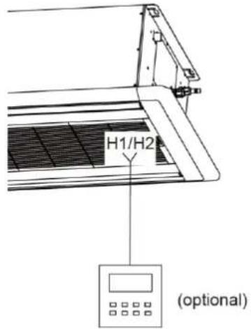
Fig. 5.4.1
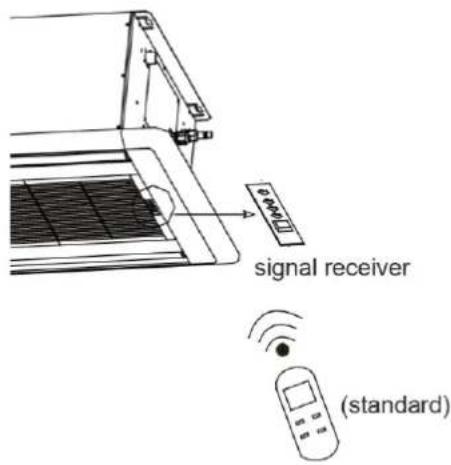
Fig. 5.4.2
2) Both IDU and wired controller are equipped with signal receiver, and available for wireless control respectively.
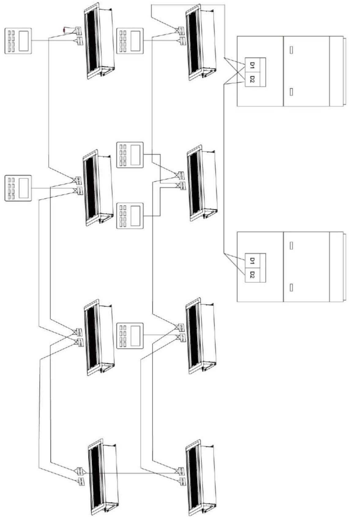
5.5 Wiring Instructions of Wired Controller and Indoor Units Network
(1) Communication wire of indoor unit and outdoor unit (or indoor unit) is connected to D1, D2.
(2) Wired controller is connected to H1, H2.
(3) One indoor unit can connect two wired controllers that must be set as master one and slave one.
(4) One wired controller can control 16 indoor unitS in maximum at the same time. (As shown in Fig.5.5.1).
| NOTICE |
| (1) The type of indoor units must be the same if they are controlled by the same wired controller. |
| (2) When the indoor unit is controlled by two wired controllers, the addresses of the two wired controllers should be different through address setting. Address 1 is for main controller; Address 2 is for slave controller. Detailed setting please refer to the instruction manual of wired controller. |
flowchart
graph TD
    A["Device 1"] --> B["Server 1"]
    B --> C["Device 2"]
    C --> D["Server 2"]
    D --> E["Client Unit"]
    E --> F["Server Unit"]
    F --> G["Data Bus"]
    G --> H["Data Bus"]
    H --> I["Data Bus"]
    I --> J["Data Bus"]
    J --> K["Data Bus"]
    K --> L["Data Bus"]
    L --> M["Data Bus"]
    M --> N["Data Bus"]
    N --> O["Data Bus"]
    O --> P["Data Bus"]
    P --> Q["Data Bus"]
    Q --> R["Data Bus"]
    R --> S["Data Bus"]
    S --> T["Data Bus"]
    T --> U["Data Bus"]
    U --> V["Data Bus"]
    V --> W["Data Bus"]
    W --> X["Data Bus"]
    X --> Y["Data Bus"]
    Y --> Z["Data Bus"]
Fig. 5.5.1
6 Routine Maintenance
| NOTICE |
| (1) Do turn off the unit and cut off the main power supply when cleaning the air conditioner to avoid electric shock or injury. |
| (2) Stand at solid table when cleaning the unit. |
| (3) Do not clean the unit with hot water whose temperature is higher than 45°C to prevent fade or deformation. |
| (4) Do not dry the filters by fire, or it may catch fire or become deformed. |
| (5) Clean the filter with a wet cloth dipped in neutral detergent. |
| (6) Please contact after-sales service staff if there is abnormal situation. |
6.1 Cleaning of Filter
(1) Remove the air filter on the air inlet for cleaning. Use a dust catcher or water to clean it. If the filter is very dirty (e.g. greasy), you can clean it using warm water (below 45^ C) that is mixed with mild detergent. Then let it dry naturally in cool places.
(2) If the air conditioner is used in dusty place, please clean the air filter regularly (generally once every 2 weeks).
6.2 Maintenance before the Seasonal Use
(1) Check if the air inlet and air outlet of indoor and outdoor unit are blocked.
(2) Check if the grounding wire is in good condition.
(3) Check if all the power cord and communication cable are securely connected.
(4) Check if any error code displayed after energized.
6.3 Maintenance after the Seasonal Use
(1) Set the unit in fan mode for half a day in a sunny day to dry the inner part of unit.
(2) When the unit won't be used for a long time, please cut off power supply for energy saving; the characters on the wired controller screen will disappear after cutting off the power supply.
7 Table of Error Codes for Indoor Unit
| Error Code | Content | Error Code | Content | Error Code | Content |
| L0 | Indoor Unit Error | LA | Indoor Units Incompatibility Error | d9 | Jumper Cap Error |
| L1 | Indoor Fan Protection | LH | Low Air Quality Warning | dA | Indoor Unit Network Address Error |
| L2 | E-heater Protection | LC | ODU-IDU Incompatibility Error | dH | Wired Controller PCB Error |
| L3 | Water Full Protection | d1 | Indoor Unit PCB Error | dC | Capacity DIP Switch Setting Error. |
| L4 | Wired Controller Power Supply Error | d3 | Ambient Temperature Sensor Error | dL | Outlet Air Temperature Sensor Error |
| L5 | Freeze protection | d4 | Inlet Pipe Temperature Sensor Error | dE | Indoor Unit CO2 Sensor Error |
| L7 | No Master Indoor Unit Error | d6 | Outlet Pipe Temperature Sensor Error | dy | Water Temperature Sensor Error |
| L8 | Power Insufficiency Protection | d7 | Humidity Sensor Error | C0 | Communication Error |
| L9 | Quantity Of Group Control Indoor Units Setting Error | d8 | Water Temperature Error | AJ | Filter Cleaning Reminder |
| o1 | Low busbar volage of indoor unit | o2 | High busbar volage of indoor unit | o3 | IPM Module Protection of Indoor Unit |
| o4 | Failure Startup of Indoor Unit | o5 | Overcurrent Protection of Indoor Unit | o6 | Current Detection Circuit Malfunction of Indoor Unit |
| o7 | Desynchronizing Protection of Indoor Unit | o8 | Communication Malfunction of Indoor Unit's Drive | o9 | Communication Malfunction of Main Mater of Indoor Unit |
| oA | Overtemperature of Indoor Unit's Module | ob | Malfunction of Temperature Sensor of Indoor Unit's Module | oC | Charging Circuit Malfunction of Indoor Unit |
| o0 | Other Drive Malfunction | db | Special Code: Field Debugging Code | ||
8 Display of Light Board
The panel of this model is without nixie tube display. The error codes will be displayed through the power light, operation light and timer light; ○, ● and ◎ stand for on, off and blink respectively.
| Power light | ○ | ◎ | ◎ | ◎ | ◎ |
| Operation light | ◎ | ● | ○ | ○ | ◎ |
| Timer light | ● | ○ | ● | ○ | ● |
Error code display sheet
| Error code | C0 | A0 | A3 | L0 | L1 | L3 | L5 | d1 | d3 | d4 | d6 | d7 | E0 | db |
| A4 | ||||||||||||||
| Power light | ◎ | ○ | ○ | ● | ● | ● | ○ | ◎ | ◎ | ◎ | ● | ○ | ● | ◎ |
| Operation light | ◎ | ◎ | ○ | ● | ○ | ◎ | ● | ○ | ● | ◎ | ◎ | ◎ | ◎ | ● |
| Timer light | ◎ | ◎ | ◎ | ◎ | ◎ | ◎ | ◎ | ◎ | ◎ | ○ | ○ | ○ | ● | ● |
| Error description | Communication error | To be debugged | Defrosting | Indoor unit error | Indoor fan protection | Water full protection | Freeze protection | Indoor unit PCB error | Ambient temperature sensor error | Inlet pipe temperature sensor error | Outlet pipe temperature sensor error | Humidity sensor error | Outdoor unit error | Field debugging code |
| oil return |
9 Troubleshooting
The air conditioner is not expected to be serviced by users. Incorrect repair may cause electric shock or fire, so please contact an authorized service center for professional service. The following checks prior to contact may save your time and money.
| Phenomenon | Troubleshooting |
| The unit can't start | 1 Power supply is not connected.2 Circuit breaker tripping caused by leakage of electricity.3 Input voltage is too low.4 Defect of main PC-board. |
| The unit stops after running for a while | 1 The inlet or outlet of ODU or IDU are blocked by obstacle. |
| Poor cooling effect | 1 The filter is dirty or blocked.2 Too heavy heat load of room(e.g. too many people).3 Door or windows is open.4 Inlet and outlet of IDU are blocked.5 Setting temperature is too high or refrigerant leaks.6 Refrigerant is insufficient (e.g. refrigerant leakage). |
| Poor heating effect | 1 The filter is dirty or blocked.2 Door or window is open.3 Setting temperature is too low.4 Refrigerant is insufficient (e.g. refrigerant leakage). |
| Indoor fan doesn't start up during heating | 1 At starting, the IDU fan could not operate till the heat exchange become hot, for preventing delivering the cool air.2 At defrosting, the IDU fan stopped due to system switch to cooling mode. For preventing delivering the cool air, and resume operating after defrosting. |
NOTICE!
If air conditioner still fails to work normally after checking and handling as described above, please stop using it immediately and contact local service center for assistance.
natural_image
Architectural detail of a modern building facade with curved roof trusses and structural beams (no text or symbols visible)
GREE
GREE ELECTRIC APPLIANCES, INC. OF ZHUHAI
Add: West Jinji Rd, Qianshan, Zhuhai, Guangdong, China, 519070
Tel: (+86-756) 8522218
Fax: (+86-756) 8669426
E-mail: gree@gree.com.cn www.gree.com
66170050084