Green 6 - Uncategorized FOCUSRITE - Free user manual and instructions
Find the device manual for free Green 6 FOCUSRITE in PDF.

| Product Type | Stereo Compressor / Limiter |
| Channels | 2 (stereo linked or dual mono) |
| Form Factor | 19-inch rack mount, 2U |
| Dimensions (W x H x D) | 482 x 89 x 250 mm |
| Weight | 5.5 kg |
| Power Supply | Internal, 100-240 V AC, 50/60 Hz |
| Power Consumption | 25 W |
| Input Type | XLR and 1/4" TRS (balanced) |
| Output Type | XLR and 1/4" TRS (balanced) |
| Compression Ratio | Variable from 1.5:1 to 20:1 |
| Attack Time | 0.1 ms to 50 ms |
| Release Time | 50 ms to 2 s |
| Threshold Range | -40 dB to +20 dB |
| Makeup Gain | 0 dB to +20 dB |
| Sidechain EQ | Fixed high-pass filter (150 Hz) |
| Bypass | Hard-wired bypass switch per channel |
| Frequency Response | 20 Hz - 20 kHz ±0.5 dB |
| Signal-to-Noise Ratio | > 90 dB |
| Total Harmonic Distortion | < 0.05% at 1 kHz |
| Maintenance | Wipe with dry cloth; do not use solvents |
| Safety | Use grounded outlet; do not remove cover |
| Spare Parts | Available from authorized service centers |
| Country of Origin | United Kingdom |
Frequently Asked Questions - Green 6 FOCUSRITE
User questions about Green 6 FOCUSRITE
0 question about this device. Answer the ones you know or ask your own.
Ask a new question about this device
Download the instructions for your Uncategorized in PDF format for free! Find your manual Green 6 - FOCUSRITE and take your electronic device back in hand. On this page are published all the documents necessary for the use of your device. Green 6 by FOCUSRITE.
USER MANUAL Green 6 FOCUSRITE
Getting to know the unit 4
Section (i): Setting Up
Installing the unit....6
Connections 6
Power Input 6
Voltage select....6
Audio inputs and Outputs 7
Input operating level....7
Section (ii): Functions
Controls....8
Threshold 9
Ratio....9
Attack and Release....9
Auto Rel....11
Make Up 1
Limiter 12
Link....12
How to use Compression....13
When to use Compression....13
When to use Limiting 14
Section (iii): Trouble Shooting
Non-Operation 14
Changing a Fuse 15
Worldwide Distributors 16
Green 6 Compressor/Limiter
Introduction
The Green 6 is a 4-channel compressor and limiter. Each channel can operate independently (so allowing you to compress and limit up to four mono signals), or channels can be linked, for example to compress and limit two stereo signals independently.
Compressors and limiters both act like automatic volume controls, turning down the volume of a signal if it gets too loud. The difference between the two is:
- A limiter sets an upper limit on the volume, and will not allow the signal to go above that volume
- A compressor reduces changes in volume, so that the dynamic range of the compressed signal is lower than the dynamic range of the input signal
The compressor reduces the dynamic range of a signal by automatically reducing the gain when it gets louder than a certain threshold. To understand a compressor, you must understand dynamic range – if you do not, you should read the section later about dynamic range.
Note that compression tends to even out a performance (particularly of stringed instruments such as guitar) since it stops the instrument getting very loud or very quiet in the mix. When compressing hard, it also reduces an instrument's attack (again, this is most noticeable with stringed instruments).
Dynamic Range
The dynamic range of a signal is the difference in volume between the quietest and loudest parts: for music, the dynamic range can be as wide as 120 dB.
Signals with wide dynamic range demand greater attention from the listener, and require listening conditions with low background noise. Consequently, in areas with high background noise, such as a restaurant, it is hard to listen to signals with a wide dynamic range – only the loud parts are heard, with the quiet parts being lost in the ambient noise. Compressing the signal reduces the dynamic range and so makes it easier to hear in such situations.
Similarly, the dynamic range of the signal can exceed that of the medium used to carry it:
- 16-bit digital recordings (such as DAT) have a theoretical maximum dynamic range of 96 dB. It is essential that you do not exceed this limit.
- Analogue tape has a dynamic range in the order of 60 dB (though noise reduction can add between 15 and 30 dB). It is not always necessary to limit dynamic range when recording onto analogue tape, as the tape saturates naturally when recording loud signals, which in some cases can be useful.
• FM radio has a dynamic range of 40 to 50 dB.
• AM radio has a dynamic range of 20 to 30 dB.
In all of these cases, you can use a compressor to restrict the dynamic range of the signal to that of the medium.
Getting to Know the Unit
The easiest way to get to know the unit, particularly if you are not familiar with using a-compressor/limiter, is to try each control in turn, so that you can hear its effect. This section gives a checklist for working through the unit's controls in a logical sequence.
When you are getting to know the unit, use it on a track that you are familiar with (for example, you could run a favourite CD through the unit); working with a familiar track makes interpretation of the results easier. Note, however, that tracks are already compressed for CD, so you may find it hard to hear the results easily. If this is the case, try using samples instead (if you have access to them), or record your own track uncompressed and then play it back through the Green 6.
- Before you start to use the unit, ensure that it is installed and set up correctly (see the Setting up section). For the purposes of getting to know the unit, connect the signal into channel 1.
-
Ensure that all the buttons, including Mast and Comp In for channel 1, are out (not lit). Adjust the signal level into the unit so that the normal signal level registers at between -3 dB and 0 dB on the top line of the meter for channel 1 (though peaks can go higher).
-
Set the controls for channel 1 in the following starting positions:
• Threshold control at maximum (fully clockwise).
• Ratio on full (control fully clockwise).
- Fast button and Auto Rel button off (not lit).
• Make up control at minimum (control fully anti-clockwise).
- Release control in its central position.
- Link 1-2 button off (not lit).
- Limiter control at maximum (fully clockwise).
-
Press the Mast button at the right of the unit (so that it lights), to enable all the compressors and limiters, then press the Comp In button for channel 1 (so that it lights) to bring channel 1 into the circuit.
-
Adjust the Threshold control for channel 1. This is the Threshold control for the compressor – as you turn it anti-clockwise, more of the signal is affected, so it becomes easier to hear the compression. The bottom line of the meter also reacts, lighting more to the right as more compression is applied.
-
Set the Threshold at -24 (fully anti-clockwise), and adjust the Make up control to restore the signal volume, so that pressing channel 1's Comp In button in and out gives a similar sort of signal level.
-
Turn down the Make up control (since further adjustments may reduce the compression and so raise the volume, and you don't want to damage any units). Adjust the Ratio control – as you reduce the ratio, so the signal is less compressed and the effect becomes less noticeable.
-
Set the Ratio control where you can easily hear the effect of compression, and adjust the Release control. The effect of release is particularly easy to hear on drums (a looped snare is good, if you have access to one). Also try pressing the Auto Rel button to hear the effect it has.
-
Turn off compression by pushing the Comp In button again (so that it is not lit), and adjust the Limiter control. This is the threshold control for the limiter – as you turn it anti-clockwise, more of the signal is affected, so it becomes easier to hear the limiting.
Installing the Unit
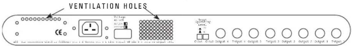
WARNING: When installing the unit, it is essential that you do not obstruct the ventilation holes on the rear or the unit will overheat.
Connections
All of the unit's connections are on the rear panel:
text_image
VENTILATION HOLES All 1000 concomms wide as follow up 1 X button up 2 1 low signal 98 min 3 6 max in signal box. Vol. loops an, each SET:25% SET:45% Input Operating Level: C:364 C:162 Output 4 Output 4 Output 3 Output 3 Output 2 Output 2 Output 1 Output 1Power Input
There is an IEC mains lead supplied in the package which should have the correct moulded plug for your country. The wiring colour code used in all Focusrite products-is:
For units shipped to the USA, Canada, Taiwan and Japan
Live - Black Neutral - White Earth - Green
For units shipped to any other country Live - Brown Neutral - Blue Earth - Green and Yellow
The chassis is connected directly to the mains safety earth. We do not provide an earth lifting switch, since such a switch can allow for a dangerous wiring arrangement.
WARNING: For safety reasons, it is absolutely IMPERATIVE that the mains safety earth is connected.
Voltage Select
The module will operate on a range of voltages. The two-position switch on the rear panel should be set to the correct voltage:
115V Set to this position if the module is to be used with voltages in the range 100V to 120V
230V Set to this position if the module is to be used with voltages in the range 200V to 250V
To comply with the safety codes in some countries, modules may be supplied without a voltage selector. In this case, the module is preset to the local supply voltage, which is clearly marked on the rear of the module. Check that the voltage is set correctly.
Japanese units: These are supplied set up for Japan only, and should only be used with mains voltages in the range 85V to 110V.
The unit will work correctly from either 50 Hz or 60 Hz power supplies, and will draw approximately 35VA from the mains supply at highest load.
Audio Inputs and Outputs
All the audio signal connections are line level, and are made via balanced stereo jacks. The wiring arrangement is:
Tip Live audio 0°
Ring Return audio 180°
Shield Screen chassis
For all inputs and outputs, the screen is connected to the chassis earth point.
You can make either balanced or unbalanced connections to the inputs and outputs. Connecting a mono jack to any of the inputs or outputs gives an unbalanced connection.
When the screen and earth wiring of the module is completed correctly, all modules which are marked with the European Community CE marking comply fully with the CE EMC regulations.
Input Operating Level
These switches set the sensitivity of the inputs and outputs to either +4 dB or -10 dB:
- +4 dB is suitable for connection to professional equipment.
- -10 dB is suitable for connection to consumer equipment.
In the +4 setting, the unit has high headroom, while in the -10 dB setting, the unit has less headroom but a very good signal to noise ratio, which is appropriate for consumer equipment.
There are two switches: one sets the sensitivity of the inputs and outputs of channels 1 and 2 as a pair; the other sets the sensitivity of the inputs and outputs of channels 3 and 4 as a pair. Therefore, if you need to connect both professional and consumer equipment, it is possible to simultaneously connect professional equipment to channels 1 and 2, and consumer equipment to channels 3 and 4 (or vice versa).
Note that the switches do not affect the overall gain of the unit, but modify the internal operating level. Therefore, with a switch out (+4 selected), an input level of +4 dBu registers as 0 on the VU meter. Similarly, with a switch in (-10 selected), an input level of -10 dBu registers as 0 on the VU meter.
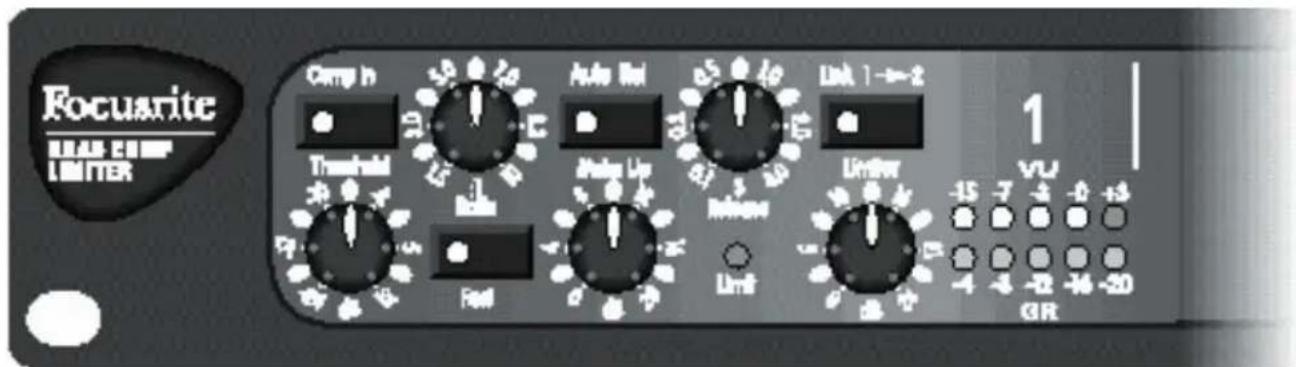
Controls
text_image
Focuarite MAX CUMP LIMITER Comp h Threshold Auto In Limit 1→2 Auto In Limit 1→2 Auto In Limit 1→2 Auto In Limit 1→2 Auto In Limit 1→2 Auto In Limit 1→2 Auto In Limit 1→2 Auto In Limit 1→2 Auto In Limit 1→2 Auto In Limit 1→2 Auto In Limit 1→2 Auto In Limit 1→2- The Comp In button switches the compressor in or out.
- The Threshold and Ratio controls set the amount of compression applied to the signal.
- The Fast button and Release control set the duration of the compression (see Attack and Release, below).
- The Auto Rel button sets an automatically controlled release time for the compressor.
• The Make up control sets the output volume of the compressed signal.
- The Link button links a channel with the next channel.
- The Limiter control sets a maximum volume for the compressed signal.
- The meter displays the level of the input signal on the top line (labelled VU), and the amount of gain reduction on the bottom line (labelled GR). The best operating level for the unit is with an input signal that registers between -3 dB and 0 dB on the top line.
- The Limiter LED indicates that the signal is being limited.
Threshold
The threshold determines when the compressor starts to compress the signal. By setting a threshold, you do not compress the whole input signal – instead, you compress the signal only when it is louder than the threshold, as shown in the following diagram:
Setting the Threshold
By setting a threshold, you determine that quieter passages maintain their natural dynamic range, and only loud passages (that go above the threshold) are compressed.

line
| I/P Range | O/P Value | |-----------|-----------| | -20 | -20 | | -10 | -10 | | 0 | 0 | | +20 | +20 |Ratio
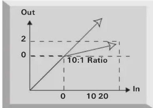
The Ratio control determines how much compression is applied to the signal. The ratio (such as 10:1) refers to the ratio of change in input level to the change in output level. So, a ratio of 10:1 means that for every 10 dB the input level exceeds the threshold level, the output level changes by 1 dB, as shown in the following diagram:
line
| In | Out | |---|---| | 0 | 0 | | 20 | 2 |Setting the Ratio
As you increase the ratio, the sound becomes tighter and the effect of the compression becomes more noticeable. A lower ratio has a softer slope, which without lowering the threshold, preserves more of the original dynamic range, since an increase in input level still results in a significant increase in output level.
Attack and Release
Attack and release determine how quickly the compressor switches on and off at the threshold. With instant attack, full compression would be applied to the signal as soon as it got louder than the threshold. Similarly, with instant release, the compressor would switch off as soon as the signal got quieter than the threshold. Varying the attack and release rates can help give more natural-sounding compression, since the optimum attack and release rates vary with the instrument being recorded, and with the performance. For example, when recording a snare drum, a fast attack and release are needed – a slow release over-compresses the signal, with all beats after the first dulled slightly because the compressor is still on.
Setting the Attack Rate
Using the unit's normal attack rate, the compressor gradually comes to full compression, instead of compressing immediately. Transient response is less affected, so maintaining the presence of each note.
Attack does not need to be fast when recording onto analogue tape. The fastest
transients are lost by saturation of the tape and become inaudible, and longer duration peaks can be controlled by the compressor, giving a more natural sound. When recording onto a digital medium such as DAT or hard disk, you may need to use the fast attack rate so that transients do not overload the medium (since this can lead to undesirable digital distortion).

text_image
Compression AttackBeforeDuring CompressionSetting the Release Rate
By slowing the release rate, the compressor recovers more slowly from compression, so it does not turn off completely when the signal returns below the threshold.
The release rate is probably the most important variable when recording rock music, since it controls loudness. Loudness is determined by the maintenance of high mean levels: compression increases the proportion of high-level signal content, and as the diagram shows, the faster the unit releases, the more low-level signal is brought to a higher level. Therefore, the faster the release rate, the higher the perceived loudness of the recording.

text_image
During Compression Release After Compression
text_image
Original Signal Compression Threshold Fast Release Overall Level Louder Compressed Level Slow Release This Portion Over Compressed Compressed Overall Level QuieterAuto Rel
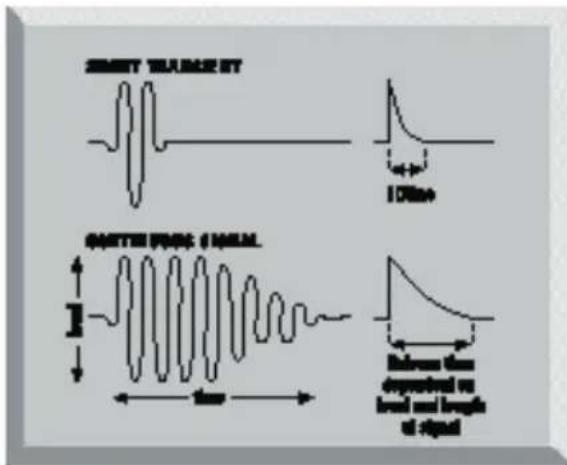
Auto Rel modifies how quickly the compressor releases after compression (that is, how quickly it stops compressing when the signal returns below the threshold). It reacts to the dynamic range of the input, so the higher the signal is above the threshold, and the longer it stays there, the longer the release. This means that fast signals that aren't compressed hard have a fast release time, while longer signals release more slowly, which makes the compression in context with the signal.
When Auto Rel is used (the button is lit), it overrides the release rate set using the release control.
text_image
SWEET TANGLES ST 100Hz GOTTER FROCK SINGEM Frequency change on level and length of signalMake Up
The Make up control adds gain to the compressed signal. Compressing a signal makes it quieter, so after you have set the compression on the signal, use the Make up control to restore the signal's original volume.
In the diagram, the compressor reduces the signal by 20 dB, which reduces the

line
| Time/Section | Value | | ------------ | ----- | | 1:1 Max Level | +20 | | 2:1 New Dynamic Range | -20 | | Original Range | +20 |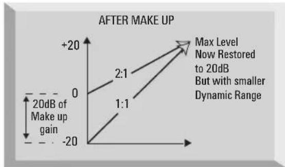
line
| 20dB of Make up gain | Max Level | | --------------------- | --------- | | 0 | 0 | | +20 | 2:1 | | -20 | 1:1 |dynamic range of the input and in so doing makes the signal quieter. Using the Make up control restores the volume of the compressed signal.
Limiter
The Limiter control determines the absolute threshold for the signal volume after compression, and does not allow the volume to go above that threshold.
Note that the threshold for the limiter is independent of the threshold for the compressor (the dB value of the limiter's threshold is an absolute value, not a relative value above the compressor's threshold). Therefore, it is possible to set the threshold for the limiter below the threshold for the compressor – if you do this, the compressor will not work.
When the limiter is working, the limit light comes on.
To turn the limiter off, set the limiter control fully clockwise to +26.
Link
This links the channel to the next channel in the Green 6, for example for recording a stereo signal.
Normally each channel of the Green 6 runs independently in mono. Controlling a stereo signal using two independent channels is very difficult: if the channels are not compressed identically, you compress one channel more than the other, thus shifting the stereo position to the left or the right. To avoid this problem, use the Link button to link the two channels that are receiving the stereo signal. This disables the controls for the right-hand channel, so the left-hand channel's controls determine the compression applied to both channels.
When linked, the channels' compressors always compress by the same amount to maintain the stereo image. However, the limiters act independently in mono, but use the threshold setting of the master channel.
Note that it is possible to link more than two channels. For example, by pressing the Link 1-2 and the Link 2-3 buttons, channels 1, 2, and 3 are all mastered by the settings applied to channel 1 and channel 4 is an independent mono channel. By pressing all of the Link buttons (Link 1-2, Link 2-3 and Link 3-4), all four channels are linked together with channel 1's controls being the "master" and channels 2, 3, and 4 being the "slave" channels.
How to Use Compression
- Using an input signal with wide dynamic range, set the controls in the following starting positions:
• Ratio in the middle (around 5:1).
• Threshold at maximum (+12).
- Auto Rel off.
• Make up control at minimum.
-
Reduce the threshold, and monitor the effect this has on the sound:
-
Listen to the reduction in the dynamic range.
- Watch the meter to see the amount of gain reduction.
As you reduce the threshold, increase the make up control to restore the level of the signal.
-
When you are close to the dynamic range you want, you need to adjust all the controls to achieve the quality of sound that you are looking for:
-
Adjust the ratio to compress softer or harder.
- Adjust the threshold to compress sooner or later.
The combination of ratio and threshold determines the maximum level of the loudest sections:
- Adjust the release to even out compression between the loud and quiet sections. If the compression sounds unnatural to you, trying using Auto Rel.
The release determines the level of the quietest signal. The combination of ratio, threshold and release determines the overall dynamic range.
- If transients are not being compressed quickly enough, use the Fast switch to give a faster attack.
- Adjust the make up control to set the level of the output signal.
When to Use Compression
Compress hard:
- To stop dropping in and out (particularly vocals – compress quite hard so they sit above the mix).
- When recording bass (for example) – if there is a lot of bass energy that can easily get out of control.
- When recording snare.
• Anything you want to maintain a continuous presence in the mix.
Compress more softly:
- When the attack is an important characteristic of the sound.
When compressing softly, set the limiter to the maximum input level of the next stage in the signal chain. This lets you compress softly without the risk of overloading the next stage.
When to Use Limiting
Set the limiter when it is important not to exceed a certain output level from the unit. The limiter sets a maximum output level for the Green 6, so you can prevent it overloading equipment later in the signal chain. For example, overloading a digital device gives unpleasant digital distortion, so set the limiter to prevent peaks in the signal that could cause an overload.
Non-Operation
If the unit does not appear to be operating correctly, perform these simple checks before assuming that it needs repair.
None of the LEDs light
Check the mains supply:
-
Is the module connected to the mains supply?
-
Is the socket switched off?
-
Is the voltage select switch on the back of the unit in the correct position?
-
If the supply is okay and the module turned on but no LEDs light, then a fuse has probably blown. See the section on changing a fuse
LEDs light, but the compressor does not appear to work properly
Check that the unit is set as you expect:
-
Is the Mast button lit?
-
Are the relevant Comp In buttons lit?
-
Is the compressor threshold set below the loudest signal level?
-
Is the limiter threshold set to a value lower than the compressor threshold?
Changing a Fuse
We strongly recommend that you do NOT attempt to change fuses unless you are absolutely certain that you know exactly what you are doing. If you are in any doubt whatsoever, contact your dealer or the factory before you open the module.
To change a fuse, if you are certain of your technical ability:
- Disconnect the mains cable.
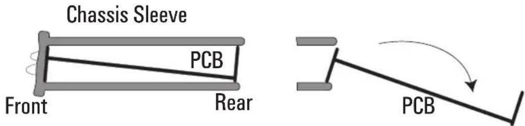
- Viewing the module from the back, remove the screws that secure the back panel.
text_image
Chassis Sleeve PCB Front Rear PCB- Carefully slide out the inside of the unit (see diagram).
- The fuse is in a holder close to the transformer. To remove the fuse, pull off the top of the fuse holder, which holds the fuse.
- Replace the fuse with a 315 mA anti-surge type.
- When you have replaced the fuse, slide the inside of the unit back into the outer cover.
- Replace the screws in the back panel.
