VWPOP65-P - TV Stand Edbak - Free user manual and instructions
Find the device manual for free VWPOP65-P Edbak in PDF.

| Product Type | TV Stand / Floor Stand |
| Brand | Edbak |
| Model | VWPOP65-P |
| Compatible Screen Size | Up to 65 inches |
| Maximum Weight Capacity | 50 kg (110 lbs) |
| VESA Compatibility | 200x200 to 600x400 mm |
| Material | Steel / Metal construction |
| Mounting Type | Freestanding floor stand |
| Adjustability | Fixed tilt, no swivel |
| Dimensions (W x H x D) | Approx. 1500 x 1200 x 400 mm |
| Base Dimensions | 800 x 500 mm |
| Weight of Stand | Approx. 15 kg |
| Color | Black |
| Assembly Required | Yes, instructions included |
| Tools Included | Hex key, screws, washers |
| Anti-Tip Safety | Includes anti-tip straps |
| Cable Management | Integrated cable guides |
| Cleaning Instructions | Wipe with a dry, soft cloth |
| Warranty | 2 years limited warranty |
| Spare Parts Availability | Contact Edbak customer service |
Frequently Asked Questions - VWPOP65-P Edbak
User questions about VWPOP65-P Edbak
0 question about this device. Answer the ones you know or ask your own.
Ask a new question about this device
Download the instructions for your TV Stand in PDF format for free! Find your manual VWPOP65-P - Edbak and take your electronic device back in hand. On this page are published all the documents necessary for the use of your device. VWPOP65-P by Edbak.
USER MANUAL VWPOP65-P Edbak
natural_image
Technical line drawing of a mechanical assembly with frame supports and mounting brackets (no text or symbols)max load capacity:
60kg
1
1. SAFETY INSTRUCTIONS:
Warning:
Please read this manual carefully prior to any installation to ensure proper assembly. The assembly should be carried out in accordance with this manual by at least two persons with sufficient qualifications and experience in assembly. EDBAK Company shall not be liable for any material or property damage or bodily injury resulting from improper assembly. Therefore, you should always follow the instructions:
- the accompanying elements are intended for mounting on walls of solid wood, brick or concrete with the use of appropriate screws that are included into the product. In the case of any other type of walls, please consult a person with sufficient qualifications in construction;
- during the assembly, please follow the instructions carefully. Otherwise it may result in product damage or even personal injury;
- before the assembly you must ensure that under the surface of the wall where the mount is to be fixed there are no power cables, water or sewage pipes or gas installations;
- make sure that the supporting surface will safely support the combined load of all attached hardware and components.
- this product is intended for indoor use only;
- this product was designed, to be installed also in public areas.
- do not install the product if it is damaged;
- while fixing the screen on the mount, please ensure that the screws are of correct length and diameter. In order to ensure the correct length and diameter, you may use the accompanying plastic pads. Use of improper screws may result in permanent product damage. Extra caution should be given with movable elements in order to prevent crushing or injury to your hands or fingers. This manual indicates such elements so please note them carefully.
The terms of the product guarantee are set forth in the guarantee card.
Keep these instruction.
2
TABLE OF CONTENTS: TOOLS REQUIRED
FOR INSTALLATION:
(NOT INCLUDED)
- Safety instructions
- Table of contents
- Tools required for installation
- Parts list
- Installation to Brick or Concrete Wall
- Installation to Wood Stud Wall
- Multiple Display Assembly - use of optional spacers.
- Attaching front plates to Display
- Attaching Display to frame
- Display Adjustment
• Service Access - Springs Adjustment
• Vertical and Horizontal Adjustment -
Display Micro adjustment
-
Cable management
-
Spirit Level
- Stud finder
- Drill
- Drill bit
- Pencil
• Phillips screwdriver - Wrench

PARTS LIST:
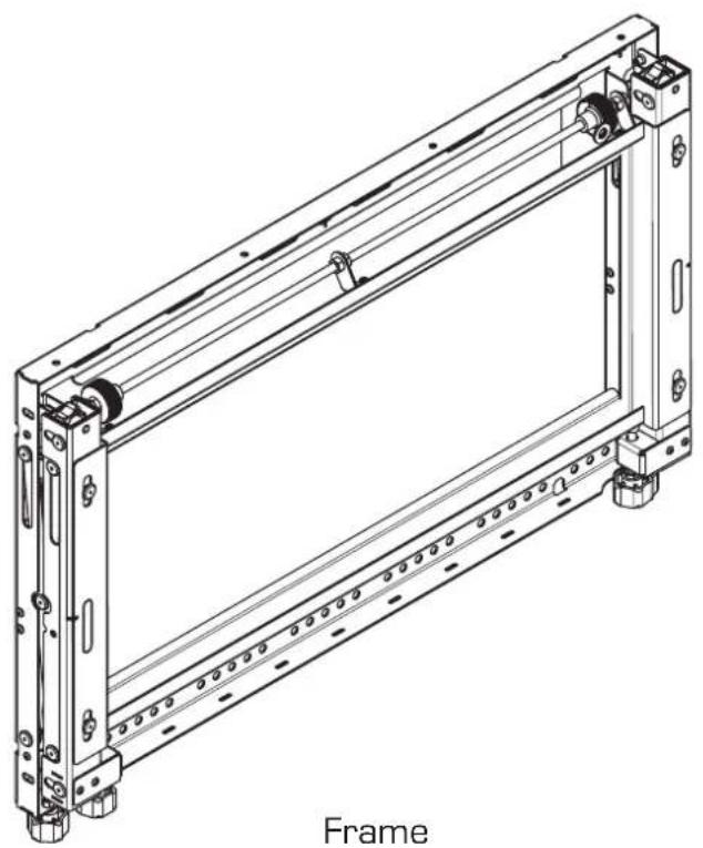
natural_image
Technical line drawing of a mechanical frame assembly (no text or symbols)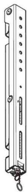
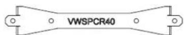
natural_image
Technical line drawing of a mechanical bracket with mounting holes and hanging chain (no text or symbols)2x mounting adapters
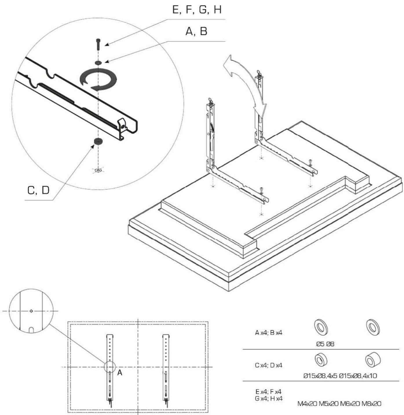
 Part list Part list | ||||
| A | ∅5 x4 | |||
| B | ∅8 x4 | |||
| C | ∅15x∅8,4x5 x4 | |||
| D | ∅15x∅8,4x10 x4 | |||
| E | 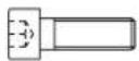 | M4x20 x4 | ||
| F | 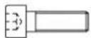 | M5x20 x4 | ||
| G | 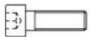 | M6x20 x4 | ||
| H | 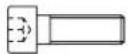 | M8x20 x4 | ||
| I | 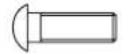 | M5x16 x2 | ||
| J |  | 10x80 x6 | ||
| K |  | x1 | ||
| L |  | x5 | ||
| M | 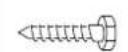 | M6x80 x6 | ||
| Screws and Allen keys (included) | ||||
 | Allen Key3, 4, 5, 6 | x1 | ||

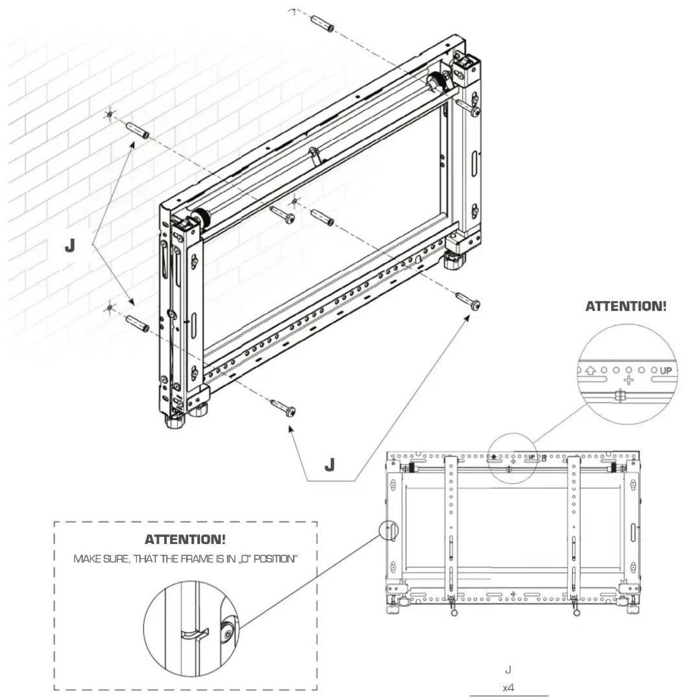
INSTALLATION TO BRICK OR CONCRETE WALL
• For the installation two people are required.
- Locate first the Mount on the wall - make sure that the mount is level.
- Mark four mounting holes. Make sure that the Mount is level. The frame must be fixed with minimum of four screws.
- Insert anchors in the holes
- Place Mount assembly over anchors and secure with four screws

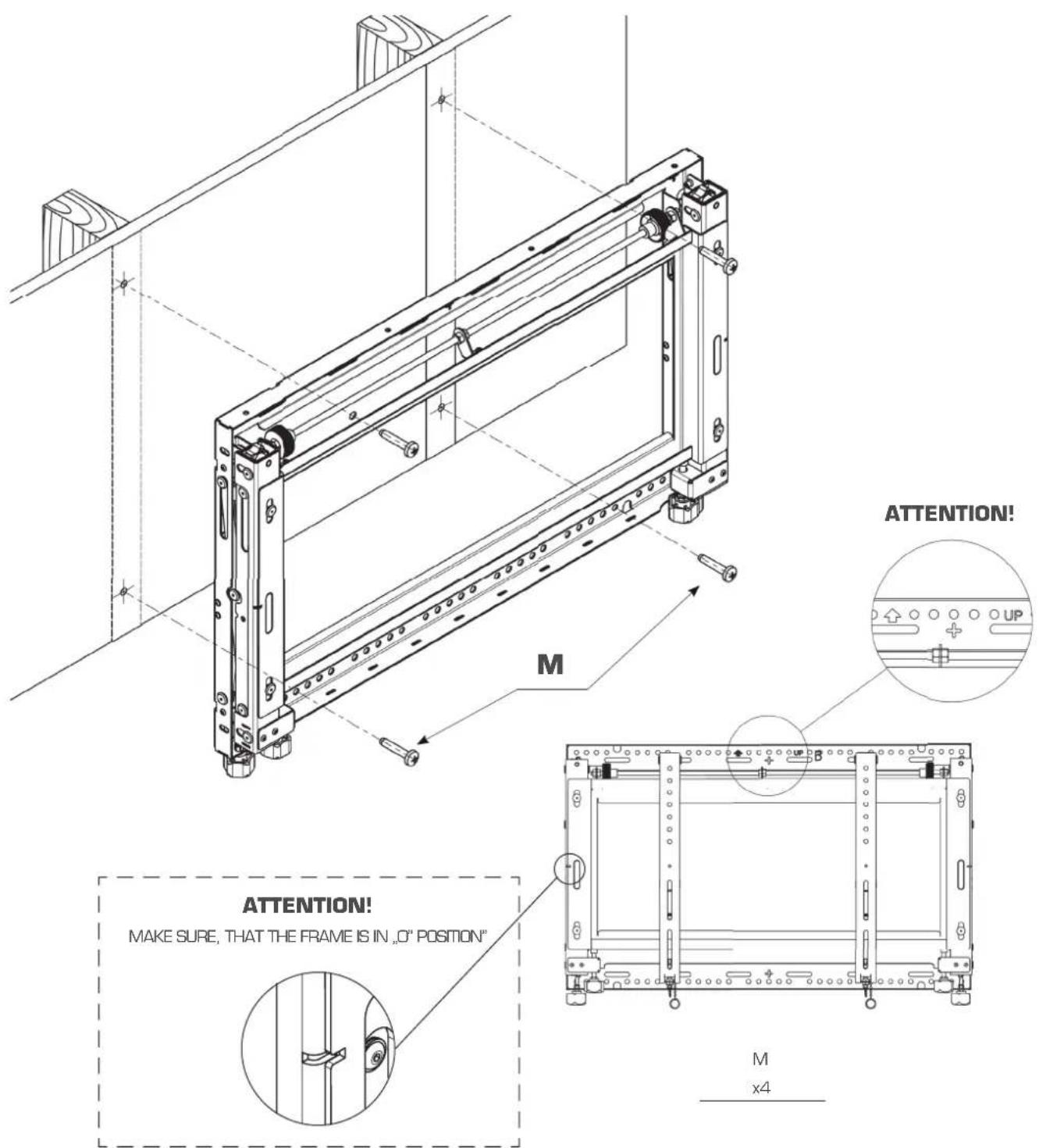
INSTALLATION TO WOOD STUD WALL
• For the installation two people are required.
- Use an edge-to-edge stud fi nder. Draw a vertical line down the stud center.
- Locate first the Mount - make sure that the mount is level.
- Mark four mounting holes. Make sure that the Mount is level. The frame must be fixed with a minimum of four screws.
- Drill four holes.
- Insert anchors in the holes.
- Place Mount assembly over anchors and secure with four screws.
ver.1.1 0814 p.5
7
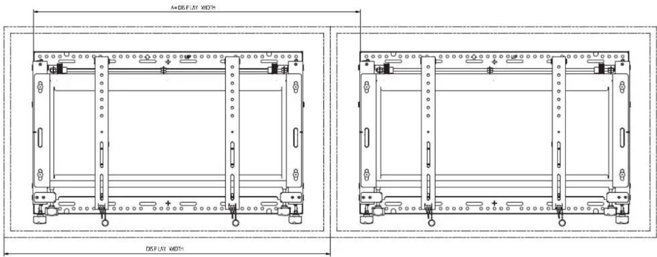
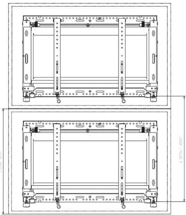
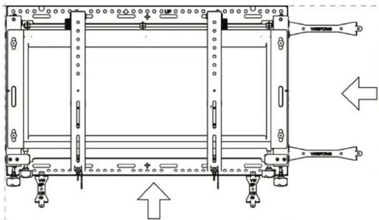
MULTIPLE DISPLAY ASSEMBLY - WITHOUT SPACERS
natural_image
Technical line drawing of a mechanical frame assembly with mounting holes and structural supports (no text or symbols)
MULTIPLE DISPLAYS ASSEMBLY- USE OF OPTIONAL SPACERS
• Install first Mount on the wall - see step 5 or 6 depending on wall structure
• Additional frames can be installed using optional spacers (not included)
- Designate a horizontal and a vertical line on the wall. Lines will help in mounting additional Mounts.
- Slide spacers into tab opening of mounted wall plate.
- Follow main instructions for correct installation of additional wall plates
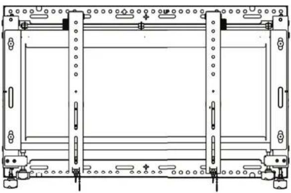
natural_image
Technical line drawing of a mechanical frame assembly (no text or symbols)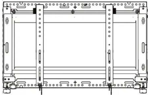
natural_image
Technical line drawing of a mechanical frame assembly (no text or symbols)ATTENTION!
HORIZONTAL ORIENTATION VERTICAL ORIENTATION

ATTACHING FRONT PLATES TO THE DISPLAY
- Place display face down on a soft surface.
- Select screw diameter and length with mounting holes on display. If it is necessary, use spacers included with screws set.
• Pull up rear part of the mounting arms. - Make sure the diamond markings on the front plates are located in the center of the display.
- Use chosen screws (and spacers if it is necessary) to connect the front plates to the display.
10
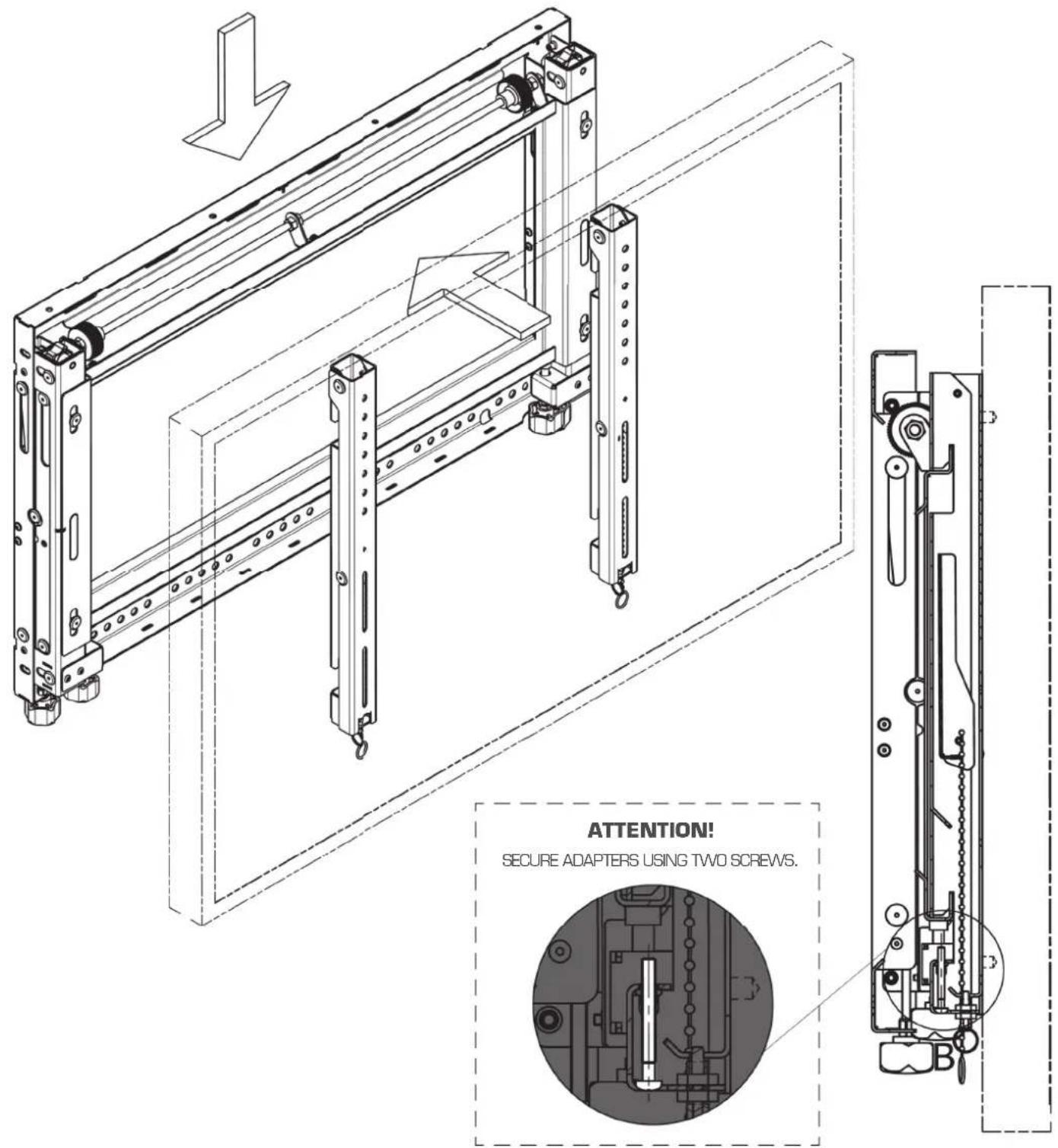
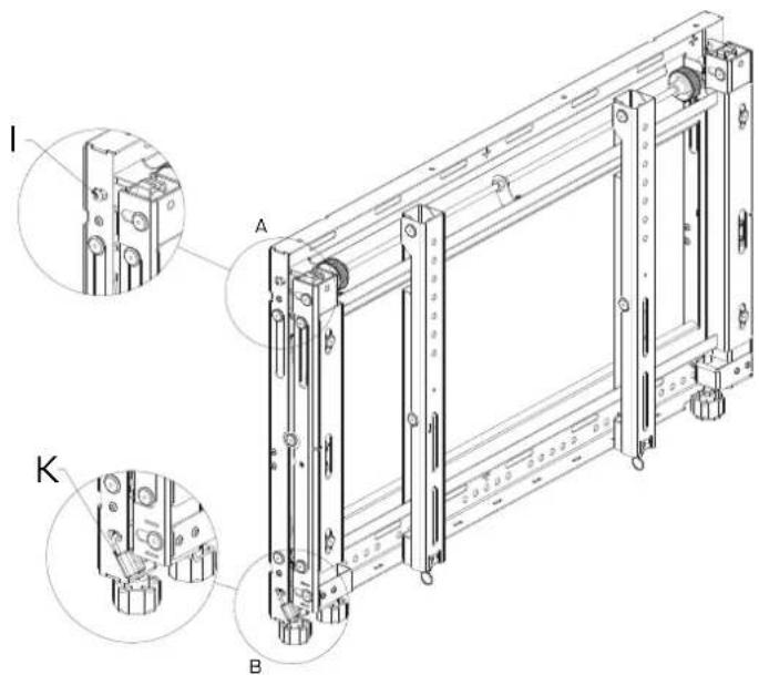
ATTACHING DISPLAY TO FRAME
- Attach Display with the front plates to the frame- two people are required.
- Place display in desired position on the frame.
- Secure each front plate using the screw, which is located at the bottom of mounting arms.
11
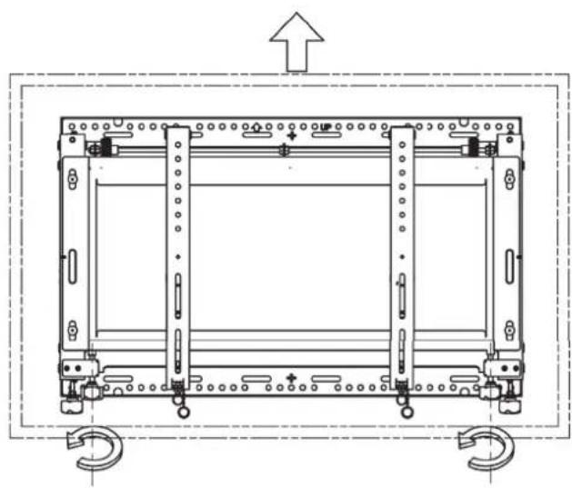
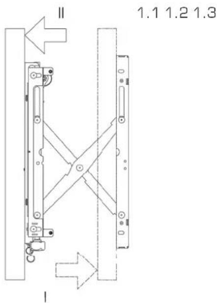
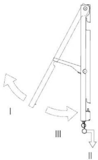
DISPLAY ADJUSTMENT
1 Springs Adjustment
2 Horizontal Adjustment
3 Vertical Adjustment
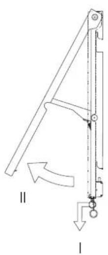
4 Tilting Adjustment
5 Display Micro adjustment
6 Security System
7 Service Access - security screws
-
SPRING ADJUSTMENT 2. HORIZONTAL ADJUSTMENT
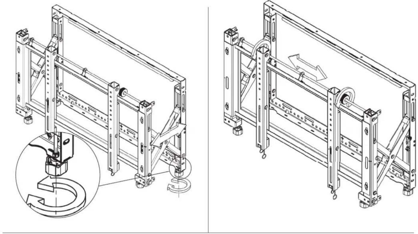
-
VERTICAL ADJUSTMENT
natural_image
Technical line drawing of a mechanical assembly with mounting holes and internal components (no text or symbols)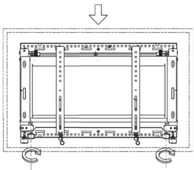
natural_image
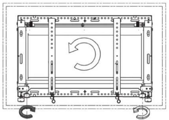
Technical line drawing of a mechanical frame assembly with mounting holes and a curved connection (no text or symbols)- TILTING ADJUSTMENT
natural_image
Technical line drawing of a mechanical assembly with a circular arrow indicating rotation (no text or symbols)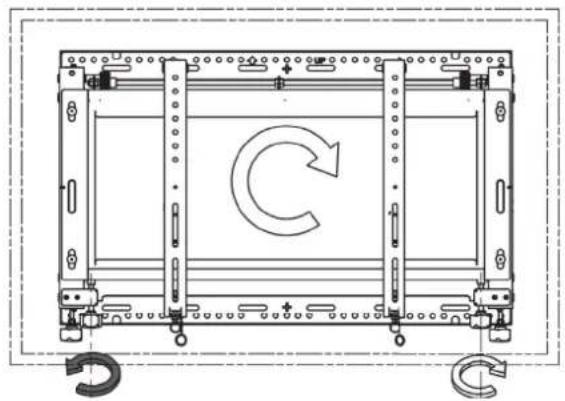
natural_image
Technical line drawing of a mechanical frame with a circular arrow indicating rotation (no text or symbols)- DISPLAY MICRO ADJUSTMENT
natural_image
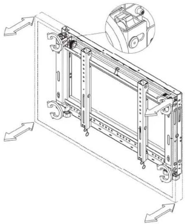
Technical line drawing of a mechanical assembly with directional arrows indicating movement (no text or symbols present)- SECURITY SYSTEM
- SERVICE ACCES
ver.1.1 0814 p.11

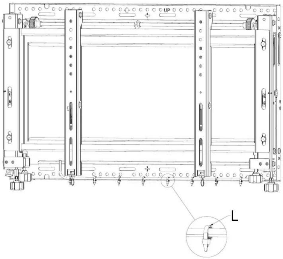
CABLE MANAGEMENT
- Cable ties "L" fixed to the cable management slots, situated on the bottom sections of the frame, can be used to secure display cables.
natural_image
Technical line drawing of a mechanical assembly with mounting brackets and a close-up inset showing a tool (no text or symbols)Contact Details
Edbak Ltd.
Piotrowice 186
23-107 Strzyżewice
Poland
Tel. +48 81 562 81 19
Fax +48 81 562 82 90
www.edbak.com
info@edbak.com