PCTVM15 - Microphone Pyle - Free user manual and instructions
Find the device manual for free PCTVM15 Pyle in PDF.

User questions about PCTVM15 Pyle
0 question about this device. Answer the ones you know or ask your own.
Ask a new question about this device
Download the instructions for your Microphone in PDF format for free! Find your manual PCTVM15 - Pyle and take your electronic device back in hand. On this page are published all the documents necessary for the use of your device. PCTVM15 by Pyle.
USER MANUAL PCTVM15 Pyle
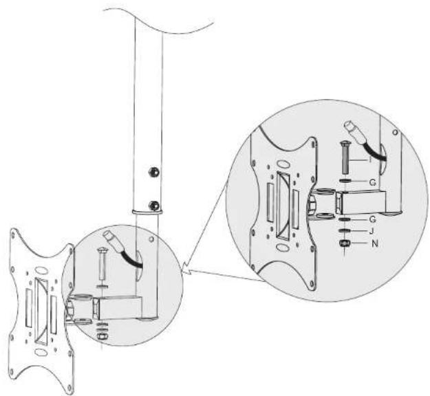
6. Installing the Display
text_image
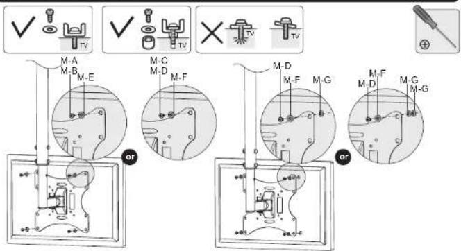
M-A M-B M-E M-C M-D M-F M-D M-F M-G M-F M-D M-G M-GNote: Choose the appropriate screws, washers and spacers (if necessary) according to the type of screen. Lift the display and match the holes on your display with the holes on the mount. Secure your display to the mount by tightening screws.
Tighten all screws but do not over tighten.
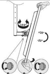
- Adjustment
text_image
180° +20° -20°Use the tilt adjusting knob to adjust your display to the desired angle then tighten it.
Maintenance
- Check that the bracket is secure and safe to use at regular intervals (at least every three months).
- Please contact your dealer if you have any questions.
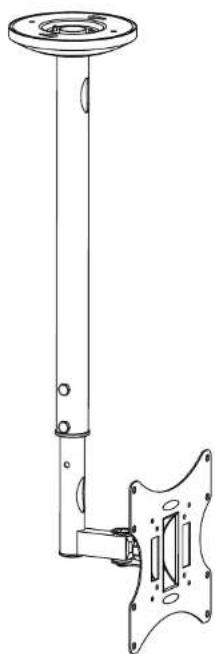
INSTALLATION MANUAL
LCD Ceiling Mount
natural_image
Technical line drawing of a vertical pole-mounted mechanical component with mounting flanges (no text or symbols)
www.pyleaudio.com

CAUTION: DO NOT EXCEED RATED LISTED WEIGHT. SERIOUS INJURY OR PROPERTY DAMAGE MAY OCCUR!
PCTVM15

75x75/100x100
200x100/200x200


NOTE: Read the entire instruction manual before you start installation and assembly.
WARNING
- Do not begin the installation until you have read and understood all the instructions and warnings contained in this installation sheet. If you have any questions regarding any of the instructions or warnings, please contact your local distributor.
- This mounting bracket was designed to be installed and utilised ONLY as specified in this manual. Improper installation of this product may cause damage or serious injury.
- This product should only be installed by someone with good mechanical ability who has basic building experience and fully understands this manual.
- Make sure that the supporting surface will safely support the combined weight of the equipment and all attached hardware and components.
- If mounting to wooden joist ceiling, make sure that mounting screws are anchored into the center of the joist. The use of a stud finder is highly recommended.
• Always use an assistant or mechanical lifting equipment to safely lift and position the equipment. - Tighten screws firmly, but do not over tighten. Over tightening can cause damage to the items. This greatly reduces their holding power.
- This product is intended for indoor use only. Using this product outdoors could lead to product failure and personal injury.
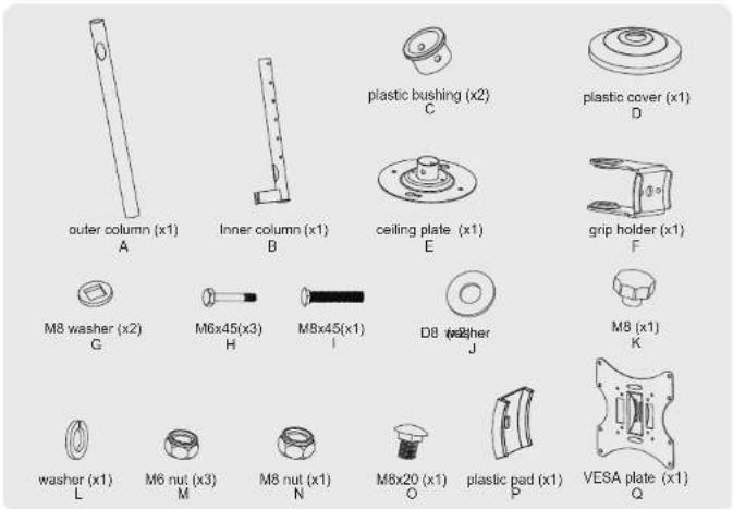
Component Checklist
IMPORTANT: Ensure that you have received all parts according to the component checklist prior to installation. If any parts are missing or faulty, telephone your local distributor for a replacement.
text_image
outer column (x1) A Inner column (x1) B plastic bushing (x2) C plastic cover (x1) D ceiling plate (x1) E grip holder (x1) F M8 washer (x2) G M6x45(x3) H M8x45(x1) I D8 washer J M8 (x1) K washer (x1) L M6 nut (x3) M M8 nut (x1) N M8x20 (x1) O plastic pad (x1) P VESA plate (x1) QPackage M
text_image
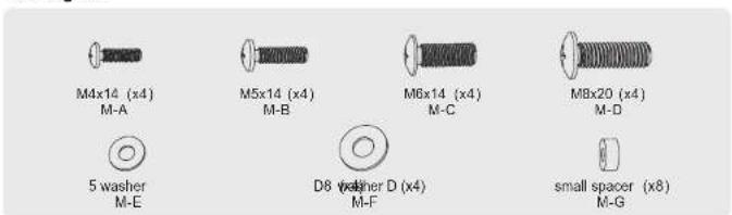
M4x14 (x4) M-A M5x14 (x4) M-B M6x14 (x4) M-C M8x20 (x4) M-D 5 washer M-E D8 washer D (x4) M-F small spacer (x8) M-GPackage W

text_image
ST6.3x55 (x4) W-A concrete anchor (x4) W-B1a. For Wooden Joist Ceiling Mounting
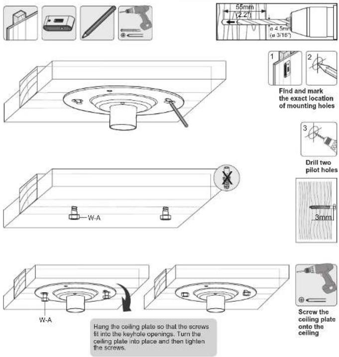
Hang the ceiling plate so that the screws fit into the keyhole openings. Turn the ceiling plate into place and then tighten the screws.

WARNING
- Make sure that mounting screws are anchored into the center of the joist. The use of a stud finder is highly recommended.
• Installers are responsible to provide hardware for other types of mounting situations.
• Installers must verify that the supporting surface will safely support the combined weight of the equipment and all attached hardware and components.
1b. For Solid Brick and Concrete Mounting

Hang the ceiling plate so that the screws fit into the keyhole openings. Turn the ceiling plate into place Do not tighten screws at this time. Fix the ceiling plate using the two other screws and then tighten all the screws!

WARNING
Installers must verify that the supporting surface will safely support the combined weight of the equipment and all attached hardware and components.
- Installing the Outer Column to the Ceiling Plate
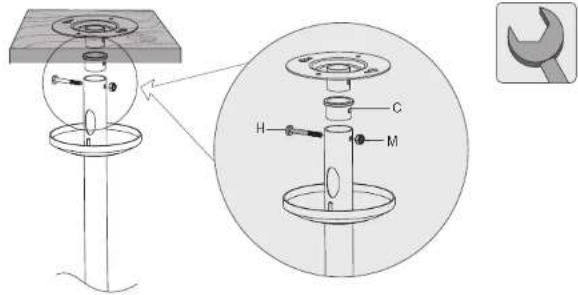
text_image
Technical diagram of a mechanical assembly with labeled components H, C, and M, including an inset view of a wrench.- Installing the Inner Column and Routing Cables
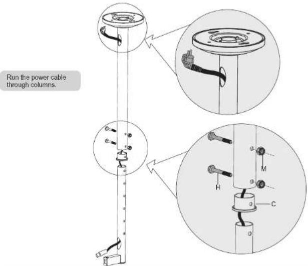
text_image
Run the power cable through columns.Insert plastic bushing and inner column into the outer column and fix them at the desired height using the correct combination of screw and nut.
- Assembling the VESA Plate
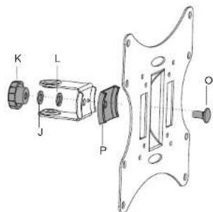
text_image
K L J P O- Installing the VESA Plate