
DB600SX - Range hood TESLA - Free user manual and instructions
Find the device manual for free DB600SX TESLA in PDF.


| Product Type | Range Hood |
| Brand | Tesla |
| Model | DB600SX |
| Mounting Type | Wall-mounted |
| Installation Mode | Ducted or Recirculating |
| Control Type | Push buttons |
| Number of Fan Speeds | 3 |
| Lighting | On/Off (bulb type not specified) |
| Grease Filter Type | Aluminum mesh |
| Grease Filter Cleaning | Wash at least once a month |
| Carbon Filter Type | Active carbon (optional, not included) |
| Carbon Filter Replacement | Every 3-4 months (recirculation mode) |
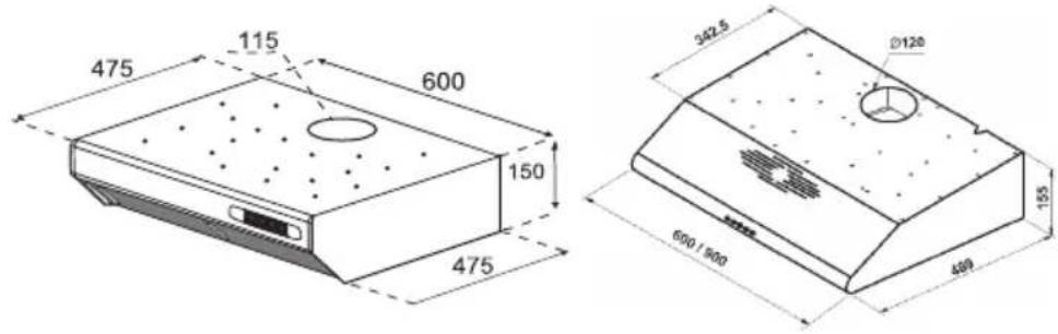
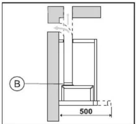
| Minimum Distance to Electric Hob | 65 cm |
| Minimum Distance to Gas Hob | 75 cm |
| Air Duct Diameter | 120 mm |
| Recirculation Mode Possible | Yes (requires carbon filter) |
| Safety Features | Do not operate without filter; use max 6A fuse |
Frequently Asked Questions - DB600SX TESLA
User questions about DB600SX TESLA
0 question about this device. Answer the ones you know or ask your own.
Ask a new question about this device
Download the instructions for your Range hood in PDF format for free! Find your manual DB600SX - TESLA and take your electronic device back in hand. On this page are published all the documents necessary for the use of your device. DB600SX by TESLA.
USER MANUAL DB600SX TESLA
| Check the electrical connection | Check the power buttons | Check the lightning buttons | Check the aluminium filters (the aluminium filters must be washed once in every month.) | Check the bulbs/spots | Check the air outlet (It must be open) | Check the carbon fitters (the carbon fitters must be changed in ewry 3 month) | |
| Cooker Hood is not working XX | |||||||
| Lightning not working XXXX | |||||||
| Cooker hood does not perform good XX |
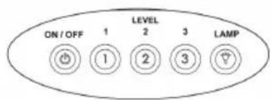
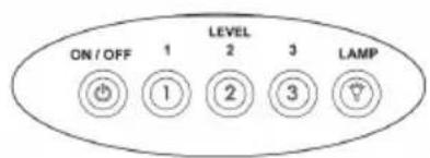
CONTROL PANEL

natural_image
Technical line drawing of a mechanical component with two circular features and a central hole (no text or symbols)
flowchart
graph TD
    A["0"] --> B["1"]
    B --> C["2"]
    C --> D["3"]
    D --> E["?"]
    E --> F["Lightbulb Icon"]
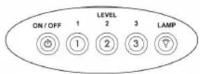

On/Off

Motor runs on Level 1

Motor runs on Level 2

Motor runs on Level 3

Lamp On / Off
natural_image
Technical line drawing of a mechanical component with no visible text or symbols

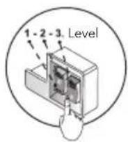
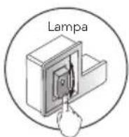
Lighting

Light On / Off
Fans
0 Fan Off
1 Fan level 1
2 Fan level 2
3 Fan level 3
ENG
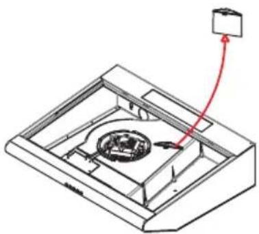
RECIRCULATION MODE

Step 1
The exhaust hole will be closed with the plastic cover.

natural_image
Technical line drawing of a mechanical device with a red arrow pointing to a component (no text or symbols present)Step 2
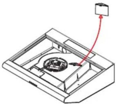
Place the charcoal filter. (optional*)
natural_image
Isometric technical diagram of a mechanical device with a red arrow indicating direction (no text or symbols)Step 3
Remove the long plastic part.

natural_image
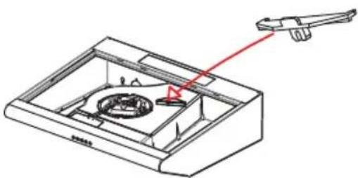
Technical line drawing of a mechanical device with a red pointer and internal components (no text or symbols)Step 4
Put the short plastic part.

natural_image
Isometric line drawing of a rectangular device with two internal compartments and mounting points (no text or symbols)Step 5
The hood is ready for use.

NOTE
For the purchase of carbon filters, please contact your dealer to obtain the corresponding reference to your model.
REPLACING THE ACTIVE CARBON FILTER (Circulating air mode only)

natural_image
Technical diagram of a mechanical assembly with rotating components and directional arrows indicating motion (no text or symbols)To maintain odor insulation levels, regular care of the filter is necessary. The active carbon filter should be replaced every 4 months.

INFORMATION
• Active carbon filters are not included in the delivery. Active carbon filters may be purchased from your dealer, customer services or a store online.
• Active carbon filters cannot be cleaned and reused.
- Remove the metal grease filter.
- Turn the old active carbon filter and pull it from its slot.
- Place a new active carbon filter in the slot, press it down and turn it.
- Reinstall the metal grease filter.
Dear User
Our aim in presenting you this manual is to ensure that you can use our aspirators, produced with the state of the art technology within our modern facilities and supplied to the market subsequent to strict quality controls, in the most efficient way.
We recommend your esteemed side read carefully this manual and keep it handy to use it again if required prior to providing information of usage.
WHAT TO DO BEFORE INSTALLATION AND USAGE
-
Do not connect the exit of your aspirator to flues where devices like stoves or water heaters are connected and where there is circulation of hot gases.
-
The distance between the bottom surface of your aspirator and the upper surface of electric ovens should be 65 cm stove while the distance should be 75 cm stove between the bottom surface of your aspirator and the upper surface of ovens using gas or mixed fuels. Otherwise, the product will be definitely out of warranty!
-
Insert the plug of your aspirator to the socket when all the usage switches on the control panel are in closed position.
-
Installation and wiring should be carried out through our authorized services. Our company is not responsible from failures arising due to installation by third parties.
-
Be careful that the power cord is not compressed and crushed during installation. A hole through which the plug of the aspirator can pass easily must be opened without cutting the aspirator cord and installation must be carried out in this way. If the power cord is damaged it must be replaced through our authorized services.
ENG
- If the supply cord is damaged, this cord must be replaced by the manufacturer or its service agent or equally qualified personnel to prevent a dangerous situation.
- Flaming foods should not be cooked under the device. They may cause fire.
- The air discharge pipe should be aluminum. The air discharge pipe should have a length of 120 mm. and louver culvert should be assembled to the outlet at the exterior without fail. Place the pipe for flue outlet outside never narrowing the diameter of the pipe (120 mm)
- Do not use non-fire-resistant filtering materials (such as paper) on the filter.
- Turn the unit off and take the plug from the socket prior to the maintenance process.
- Use max 6 amp fuse for your safety.

NOTE
Your aspirator is produced to work with and without flue connection.
USAGE WITH FLUE
There is an air exit on your aspirator. Flue connection will be made from this air exit. A flue adapter suitable for 120 mm diameter is supplied with the aspirator. It is recommended to use spiral pipe with a diameter of 120 mm in the flue pipe. Pipe connection should be as short as possible and with least number of elbows for efficient operation of your aspirator.
USAGE WITHOUT FLUE
Closet shelves or cabinet ceilings that may prevent the outlet pipe should be cut in the same size to ensure air circulation in the kitchen. The air sucked by the aspirator is given into the kitchen in usage without flue. A culvert should be installed to the mouth of the pipe on the facade. Replace your carbon filter every 3 months in average.
FILTER CHANGE (WASHING)
- Remove the cassette filter by pushing the latches inside.
- Place one side of the filter into the house and secure the filter by pressing inside and leaving the latch of the other side.
IMPORTANT NOTICE
-
The distance between the bottom surface of your aspirator and the upper surface of electric ovens should be 65 cm stove while the distance should be 75 cm stove between the bottom surface of your aspirator and the upper surface of ovens using gas or mixed fuels. Otherwise, the product will be definitely out of warranty!
-
Place the flue exit in the same diameter (without making it smaller).
-
Do not operate your aspirator without filter.
-
Do not change the filter while your aspirator is running.
-
Operate your aspirator while you operate your stove.
-
Do not open your aspirator when you feel a gas leak.
-
Wipe your aspirator with cloth soaked in warm water with detergent and dry.
-
You may use the aluminum filter by washing at least once a month
-
Replace the oil filter with synthetic fiber every 2 months
-
Replace the imported carbon filter every 3 months in use without flue.
-
Ventilation of the room should be sufficient if you are operating your aspirator with products using gas or similar fuel at the same time.
- Ensure that the children and people with physical and mental disabilities do not use the appliance.
MOUNTING AND INSTALLATION OF THE EXTRACTION HOOD
There are 2 eyelet marks on the back part of your hood for hanging the hood.
- Determine the place of the hood which has to be hanged on a plane surface and at a height of 65 cm from the oven and mark the hanging hole places.
- Use a 08 mm drill for drilling and drive the screws by placing dowels.
- Hang the hood by using the hanging screws and fix it.
- There are 2 flues in the parcel of the hood. The short flue is used for selling the height and the short flue will be placed in the long flue.
- Place both flues on the hood at the same time. Make the flue height adjustment by sliding the short height adjustment flue from inside upwards.
Drill the 2 eyelet marks on the back part of the hood and hang the hood on the wall by placing dowels and the screws. Place the long flue on the hood by sliding it down in the short flue. In this may assembly of the hood will be completed.
KLASIČNA NAPA
UGRADBENA NAPA

UGRADBENA NAPA

| Provjerite električnu instalaciju | Provjerite uključi/isključi dugme | Provjerite dugme za svjetlo | Provjerite aluminijumske filtere (obavezno čišćenje jednom mjesečno) | Provjerite sijalicu | Provjerite otvor za vazduh (mora da bude otvoren) | Provjerite ugljene filtere (moraju da se mjenjaju na svaka tri mjeseca) | |
| Napa ne radi XX | |||||||
| Svjetlo ne radi XXXX | |||||||
| Napa ne radi dobro XX |
UPRAVLJAČKA PLOČA

natural_image
Technical line drawing of a mechanical component with two circular features and internal features (no text or symbols)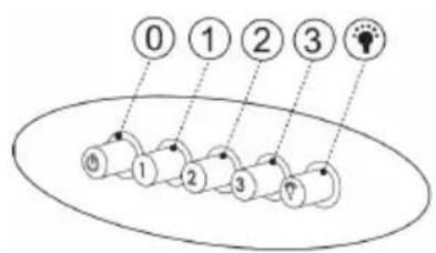

natural_image
Technical line drawing of a mechanical component with no visible text or symbols


Svjetlo
natural_image
Technical line drawing of a mechanical device with a red arrow pointing to a circular component (no text or symbols present)Korak 2
Postavite ugljeni filter. (opciono)

natural_image
Isometric technical diagram of a mechanical device with a central component and red arrow indicating direction (no text or symbols)Korak 3
Uklonite dugački plastični dio.

natural_image
Technical line drawing of a mechanical device with a red arrow pointing to a component (no text or symbols present)Korak 4
Stavite kratki plastični dio.

natural_image
Line drawing of a rectangular electronic device with two internal compartments and mounting holes (no text or symbols)Korak 5
natural_image
Technical diagram of a mechanical assembly with rotating components and directional arrows indicating motion (no text or symbols)Redovna briga o filteru je neophodna. Ugljene filtere treba mijenjati na svaka četiri mjeseca.

INFORMACIJE
- Ugljeni filteri se ne dobijaju kupovinom nape. Mogu da se nabave preko maloprodaje ili servisnog centra.
-
Ugljeni filteri ne mogu da se čiste ili ponovo koriste.
-
Uklonite metalni filter.
- Okrenite stari ugljeni filter i izvadite ga.
- Stavite novi ugljeni filter, pristisnite i okrenite ga.
- Vratite metalni filter na svoje mjesto.
GENERALNO
natural_image
Technical line drawing of a mechanical component with two circular features and a central hole (no text or symbols)
flowchart
graph TD
    A["0"] --> B["1"]
    B --> C["2"]
    C --> D["3"]
    D --> E["?"]
    E --> F["Lightbulb Icon"]

natural_image
Technical line drawing of a mechanical component with no visible text or symbols

Svjetlo

natural_image
Technical line drawing of a mechanical device with a red arrow pointing to a component (no text or symbols present)Korak 2
Postavite ugljeni filter. (opciono)
natural_image
Isometric technical diagram of a mechanical device with a central rotating component and a red arrow indicating direction (no text or symbols)Korak 3
Uklonite dugački plastični dio.
natural_image
Technical line drawing of a mechanical device with a red pointer and internal components (no text or symbols)Korak 4
Stavite kratki plastični dio.

natural_image
Isometric line drawing of a rectangular device with two internal compartments and mounting points (no text or symbols)Korak 5
natural_image
Technical diagram of a mechanical assembly with rotating components and directional arrows indicating motion (no text or symbols)Redovna briga o filteru je neophodna. Ugljene filtere treba mijenjati na svaka četiri mjeseca.

INFORMACIJE
- Ugljeni filteri se ne dobijaju kupovinom nape. Mogu se nabaviti preko trgovca kod kojeg ste kupili uređaj ili servisnog centra.
-
Ugljeni filteri se ne mogu čistiti ili ponovo koristiti.
-
Uklonite metalni filter.
- Okrenite stari ugljeni filter i izvadite ga.
- Stavite novi ugljeni filter, pristisnite i okrenite ga.
- Vratite metalni filter na svoje mjesto.
GENERALNO
Pažljivo pročitajte uputstvo koje se odnosi na instalaciju i održavanje. Uputstvo držite na mjestu koje je dostupno. Ovaj model uređaja je napravljen kao ispušnja verzija (recirkulacija zraka) ili kao opcija sa filterima (unutrašnje kretanje zraka) nape.
SIGURNOSNE MERE
Obratiti pažnju kada napa radi istovremeno iznad otvorenog plamena koji reagira na protok zraka, jer napa može smanjiti potrebnu količinu kisika, koja je neophodna za normalan rad štednjaka sa otvorenirn plamenom. Negativni pritisak u okruženju ne smije preći 4Pa (4x10⁻⁵bar). Omogućite adekvatnu ventilaciju za sigurniji rad nape.
natural_image
Technical line drawing of a mechanical component with mounting holes and a circular detail (no text or symbols)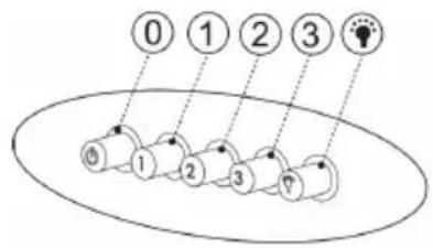
flowchart
graph TD
    A["0"] --> B["1"]
    B --> C["2"]
    C --> D["3"]
    D --> E["4"]
    E --> F["5"]
    F --> G["6"]
    G --> H["7"]
    H --> I["8"]
    I --> J["9"]
    J --> K["10"]
    K --> L["11"]
    L --> M["12"]
    M --> N["13"]
    N --> O["14"]
    O --> P["15"]
    P --> Q["16"]
    Q --> R["17"]
    R --> S["18"]
    S --> T["19"]
    T --> U["20"]


Включено/Исклучено

natural_image
Technical line drawing of a mechanical component with a meshed base and mounting bracket (no text or symbols)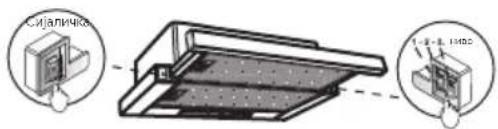
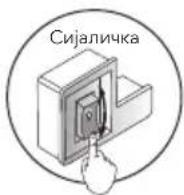
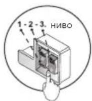
Сијаличка
natural_image
Technical line drawing of a mechanical device with a red arrow pointing to a circular component (no text or symbols present)Чекор 2
natural_image
Isometric technical diagram of a mechanical assembly with a central component and directional arrow (no text or symbols)Чекор 3
natural_image
Technical line drawing of a mechanical device with a red arrow pointing to a component (no text or symbols present)Чекор 4
natural_image
Isometric line drawing of a rectangular device with two internal compartments and mounting holes (no text or symbols)Чекор 5
natural_image
Technical diagram of a mechanical device with rotating components and directional arrows indicating motion (no text or symbols)natural_image
Technical line drawing of a mechanical component with holes and a circular feature (no text or symbols)
flowchart
graph TD
    A["①"] --> B["②"]
    B --> C["③"]
    C --> D["④"]
    D --> E["⑤"]
    E --> F["⑥"]
    style A fill:#f9f,stroke:#333
    style B fill:#f9f,stroke:#333
    style C fill:#f9f,stroke:#333
    style D fill:#f9f,stroke:#333
    style E fill:#f9f,stroke:#333
    style F fill:#f9f,stroke:#333


natural_image
Technical line drawing of a mechanical component with a meshed base and mounting bracket (no text or symbols)

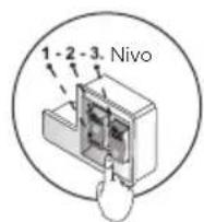
Svetlo
natural_image
Technical line drawing of a mechanical device with a red arrow pointing to a circular component (no text or symbols present)Korak 2
Postavite ugljeni filter. (opciono)

natural_image
Isometric technical diagram of a mechanical assembly with a central component and a red arrow indicating direction (no text or symbols)Korak 3
natural_image
Technical line drawing of a mechanical device with a red arrow pointing to a component (no text or symbols present)Korak 4
Stavite kratki plastični deo.
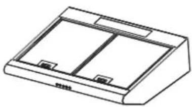
natural_image
Line drawing of a rectangular electronic device with two internal compartments and mounting holes (no text or symbols)Korak 5
Aspirator je spreman za upotrebu.

NAPOMENA
Za nabavku ugljenih filtera, obratite se svojoj maloprodaji ili servisnom centru.
ZAMENA UGLJENIH FILTERA (samo za režim cirkulacije)

natural_image
Technical diagram of a mechanical assembly with rotating components and directional arrows indicating motion (no text or symbols)- CONTROL PANEL
- Lighting
- Fans
- RECIRCULATION MODE
- Step 1
- Step 2
- Step 3
- Step 4
- Step 5
- REPLACING THE ACTIVE CARBON FILTER (Circulating air mode only)
- INFORMATION
- Dear User
- WHAT TO DO BEFORE INSTALLATION AND USAGE
- ENG
- NOTE
- USAGE WITH FLUE
- USAGE WITHOUT FLUE
- FILTER CHANGE (WASHING)
- IMPORTANT NOTICE
- MOUNTING AND INSTALLATION OF THE EXTRACTION HOOD
- KLASIČNA NAPA
- UGRADBENA NAPA
- UPRAVLJAČKA PLOČA
- Svjetlo
- Korak 2
- Korak 3
- Korak 4
- Korak 5
- INFORMACIJE
- GENERALNO
- SIGURNOSNE MERE
- Сијаличка
- Чекор 2
- Чекор 3
- Чекор 4
- Чекор 5
- Svetlo
- NAPOMENA
- ZAMENA UGLJENIH FILTERA (samo za režim cirkulacije)
Brand : TESLA
Model : DB600SX
Category : Range hood