AM-160-A - Multimeter Amprobe - Free user manual and instructions
Find the device manual for free AM-160-A Amprobe in PDF.

User questions about AM-160-A Amprobe
0 question about this device. Answer the ones you know or ask your own.
Ask a new question about this device
Download the instructions for your Multimeter in PDF format for free! Find your manual AM-160-A - Amprobe and take your electronic device back in hand. On this page are published all the documents necessary for the use of your device. AM-160-A by Amprobe.
USER MANUAL AM-160-A Amprobe
natural_image
Abstract geometric logo composed of white triangles on black background (no text or symbols)AMPROBE®
AM-140-A
AM-160-A
Precision DMM with TRMS & PC Connection
Users Manual
- Mode d'emploi
• Bedienungshandbuch - Manual d'Uso
- Manual de uso
AM-140-A
AM-160-A
Precision DMM with TRMS & PC Connection
Users Manual
Limited Warranty and Limitation of Liability
Your Amprobe product will be free from defects in material and workmanship for 1 year from the date of purchase. This warranty does not cover fuses, disposable batteries or damage from accident, neglect, misuse, alteration, contamination, or abnormal conditions of operation or handling. Resellers are not authorized to extend any other warranty on Amprobe's behalf. To obtain service during the warranty period, return the product with proof of purchase to an authorized Amprobe Test Tools Service Center or to an Amprobe dealer or distributor. See Repair Section for details. THIS WARRANTY IS YOUR ONLY REMEDY. ALL OTHER WARRANTIES - WHETHER EXPRESS, IMPLIED OR STAUTORY - INCLUDING IMPLIED WARRANTIES OF FITNESS FOR A PARTICULAR PURPOSE OR MERCHANTABILITY, ARE HEREBY DISCLAIMED. MANUFACTURER SHALL NOT BE LIABLE FOR ANY SPECIAL, INDIRECT, INCIDENTAL OR CONSEQUENTIAL DAMAGES OR LOSSES, ARISING FROM ANY CAUSE OR THEORY. Since some states or countries do not allow the exclusion or limitation of an implied warranty or of incidental or consequential damages, this limitation of liability may not apply to you.
Repair
All test tools returned for warranty or non-warranty repair or for calibration should be accompanied by the following: your name, company's name, address, telephone number, and proof of purchase. Additionally, please include a brief description of the problem or the service requested and include the test leads with the meter. Non-warranty repair or replacement charges should be remitted in the form of a check, a money order, credit card with expiration date, or a purchase order made payable to Amprobe® Test Tools.
In-Warranty Repairs and Replacement – All Countries
Please read the warranty statement and check your battery before requesting repair. During the warranty period any defective test tool can be returned to your Amprobe® Test Tools distributor for an exchange for the same or like product. Please check the "Where to Buy" section on www.amprobe.com for a list of distributors near you. Additionally, in the United States and Canada In-Warranty repair and replacement units can also be sent to a Amprobe® Test Tools Service Center (see next page for address).
Non-Warranty Repairs and Replacement – US and Canada
Non-warranty repairs in the United States and Canada should be sent to a Amprobe® Test Tools Service Center. Call Amprobe® Test Tools or inquire at your point of purchase for current repair and replacement rates.
In USA In Canada
Amprobe Test Tools Amprobe Test Tools
Everett, WA 98203 Mississauga, ON L4Z 1X9
Tel: 888-993-5853 Tel: 905-890-7600
Fax: 425-446-6390 Fax: 905-890-6866
Non-Warranty Repairs and Replacement – Europe
European non-warranty units can be replaced by your Amprobe® Test Tools distributor for a nominal charge. Please check the "Where to Buy" section on www.amprobe.com for a list of distributors near you.
Amprobe® Test Tools Europe
In den Engematten 14
79286 Glottertal, Germany
tel: +49 (0) 7684 8009 - 0
*(Correspondence only – no repair or replacement available from this address. European customers please contact your distributor.) customers please contact your distributor.)

text_image
500059 Δ Δ REC0 CREST® Δ 500000 48mΩ/T:T2 14-20mA SELECT RANGE ~Hz HOLD Precision DMM w/ TRMS & PE Connection T1 T2 Ω A mA % 4-20mA μA OFF mV dBm OFF MACK A mA μA COM ΩV-H -T2+ MAX 16A HBC FUSED MAX 0.5A HBC FUSED -T1+ MAX 1000V CAT R 600V CAT R AMPROBE AM-160-A1 5-4/5 digits 500000 counts LCD display
2 Push-buttons for special functions & features
3 Selector to turn the Power On or Off and select a function
4 Input Jack for 10A (+) (20A for 30sec) current, and for T2 (-) function
5 Input Jack (+) for all functions EXCEPT current ( A, mA, A) and T2 functions
6 Common (Ground reference) Input Jack (-) for all functions EXCEPT T2 function
⑦ Input Jack (+) for milli-amp, microamp, and T2 (+) functions
SYMBOLS....1
UNPACKING AND INSPECTION ....3
FEATURES....3
OPERATION......5
AC Voltage, DC Voltage, DC+AC Voltage, & \~ Hz Line Level Frequency ....5
Hz Logic Level Frequency and % Duty Cycle functions .....7
T1-T2 Dual Channels Temperature function (AM-160-A only) 8
Ω Resistance, ••••• Continuity functions .....9
Capacitance, Diode test function 9
μA, mA, A, and %4-20mA Current functions 10
PC-COMM computer interface capabilities ....11
MAX/MIN RECORDING mode ....12
CREST Capture (Instantaneous Peak Hold) mode ....12
Relative Zero mode 12
500000 high resolution stable mode 12
Backlighted display 12
Manual or Auto-ranging ....13
Hold H 13
Set Beeper Off ....13
Beep-Jack™ Input Warning 13
Intelligent Auto Power Off (APO) 13
Disabling Auto Power Off ....13
SPECIFICATION....14
MAINTENANCE AND REPAIR ......21
Trouble shooting 22
Cleaning and Storage 22
Battery and Fuse replacement ....22
SYMBOLS
| Caution ! Risk of electric shock | |
| Caution ! Refer to the explanation in this Manual | |
| Double Insulation or Reinforced insulation | |
| Alternating Current (AC). | |
| Direct Current (DC). | |
| Fuse | |
| Earth (Ground) | |
| Please remove all the test leads before preforming maintenance, cleaning, battery replacement, fuse replacement, etc | |
| CE | Complies with European Directives |
| Conforms to relevant Australian standards | |
| Do not dispose of this product as unsorted municipal waste. Contact a qualified recycler for disposal |
Safety Information
This manual contains information and warnings that must be followed for operating the instrument safely and maintaining the instrument in a safe operating condition. If the instrument is used in a manner not specified by the manufacturer, the protection provided by the instrument may be impaired. The meter is intended only for indoor use.
The meter protection rating, against the users, is double insulation per IEC61010-1 2nd Ed., EN61010-1 2nd Ed., UL61010-1 2nd Ed. and CAN/CSA C22.2 No. 61010.1-0.92 to Category III 1000 Volts AC & DC and Category IV 600 Volts AC & DC.
AM-140-A Terminals (to COM) measurement category:
V : Category III 1000 Volts AC & DC, and Category IV 600 Volts AC & DC.
A / mAμA : Category III and Category IV 600 Volts AC and 300 Volts DC.
AM-160-A Terminals (to COM) measurement category:
V / A / mAμA : Category III 1000 Volts AC & DC, and Category IV 600 Volts AC & DC.
Per IEC61010-1 2nd Ed. (2001) Measurement Category
Measurement Category IV (CAT IV) is for measurements performed at the source of the low-voltage installation. Examples are electricity meters and measurements on primary overcurrent protection devices and ripple control units.
Measurement Category III (CAT III) is for measurements performed in the building installation. Examples are measurements on distribution boards, circuit-breakers, wiring, including cables, bus-bars, junction boxes, switches, socket-outlets in the fixed installation, and equipment for industrial use and some other equipment, for example, stationary motors with permanent connection to the fixed installation.
Measurement Category II (CAT II) is for measurements performed on circuits directly connected to the low voltage installation. Examples are measurements on household appliances, portable tools and similar equipment.
Terms In This Manual
⚠ WARNING - identifies conditions and actions that could result in serious injury or even death to the user.
⚠️ CAUTION - identifies conditions and actions that could cause damage or malfunction in the instrument.
⚠ WARNING
To reduce the risk of fire or electric shock, do not expose this product to rain or moisture. To avoid electrical shock hazard, observe the proper safety precautions when working with voltages above 60 VDC or 30 VAC rms. These voltage levels pose a potential shock hazard to the user. Do not touch test lead tips or the circuit being tested while power is applied to the circuit being measured. Keep your fingers behind the finger guards of the test leads during measurement. Inspect test leads, connectors, and probes for damaged insulation or exposed metal before using the instrument. If any defects are found, replace them immediately. Do not measure any current that exceeds the current rating of the protection fuse. Do not attempt a current measurement to any circuit where the open circuit voltage is above the protection fuse voltage rating. Suspected open circuit voltage should be checked with voltage functions. Never attempt a voltage measurement with the test lead inserted into the A/mA or A input jack. Only replace the blown fuse with the proper
rating as specified in this manual. Only use the accompanied test leads, or replace with the same rating or better.
⚠️ CAUTION
Disconnect the test leads from the test points before changing functions. Always set the instrument to the highest range and work downward for an unknown value when using manual ranging mode.
CENELEC Directives
The instruments conform to CENELEC Low-voltage directive 2006/95/EC and Electromagnetic compatibility directive 2004/108/EC
UNPACKING AND INSPECTION
Your shipping carton should include:
1 AM-140-A or AM-160-A Meter
1 Test Leads (Black x 1; Red x 1)
1 K Type thermal couple with banana plug (For AM-160-A only)
1 Users Manual
1 Single Alkaline 9V battery; NEDA1604A, JIS6AM6 OR IEC6LF22(Installed)
If any of the items are damaged or missing, return the complete package to the place of purchase for an exchange.
FEATURES
Average sensing RMS calibrated
RMS (Root-Mean-Square) is the term used to describe the effective or equivalent DC value of an AC signal. Most digital multimeters use average sensing RMS calibrated technique to measure RMS values of AC signals. This technique is to obtain the average value by rectifying and filtering the AC signal. The average value is then scaled upward (calibrated) to read the RMS value of a sine wave. In measuring pure sinusoidal waveform, this technique is fast, accurate, and cost effective. In measuring non-sinusoidal waveforms, however, significant errors can be introduced because of different scaling factors relating average to RMS values.
AC True RMS
AC True RMS, normally refers as True RMS, identifies a DMM function that is AC coupled, and responds accurately only to the effective RMS AC component value regardless of the waveforms. However, DC component plays an important role in the distorted non-symmetrical waveforms, and will also be of interest sometimes. A full wave rectified sine waveform is a good example, and the AC true RMS function will only give the AC component reading which is at 43.6% of the total effective DC+AC RMS reading.
DC+AC True RMS
DC+AC True RMS calculates both of the AC and DC components given by the expression ^2 + (AC rms)^2 when making measurement, and can respond accurately to the total effective RMS value regardless of the waveform. Distorted waveforms with the presence of DC components and harmonics may cause:
• Overheated transformers, generators and motors to burn out faster than normal
- Circuit breakers to trip prematurely
- Fuses to blow
- Neutrals to overheat due to the triplen harmonics present on the neutral
- Bus bars and electrical panels to vibrate
AC Bandwidth
AC bandwidth of a DMM is the range of frequencies over which AC measurements can be made within the specified accuracy. It is not the frequency measurement function, and is the frequency response of the AC functions. A DMM cannot accurately measure the AC value with frequency spectrums beyond the AC bandwidth of the DMM. Therefore, wide AC bandwidth plays an important role in high performance DMMs. In reality, complex waveforms, noise and distorted waveforms contain much higher frequency spectrum than its fundamental.
NMRR (Normal Mode Rejection Ratio)
NMRR is the DMM's ability to reject unwanted AC noise effect that can cause inaccurate DC measurements. NMRR is typically specified in terms of dB (decibel). This series has a NMRR specification of >60dB at 50 and 60Hz, which is a good and definite ability to reject the effect of AC noise when making DC measurements.
CMRR (Common Mode Rejection Ratio)
Common mode voltage is voltage present on both the COM and VOLTAGE input terminals of a DMM, with respect to ground. CMRR is the DMM's ability to reject common mode voltage effect that can cause digit rolling or offset in voltage
measurements. This series has a CMRR specifications of >80dB at DC to 60Hz in ACV function; and >120dB at DC, 50 and 60Hz in DCV function. If neither NMRR nor CMRR specification is specified, a DMM's performance will be uncertain.
Analog bar-graph
The analog bar graph provides a visual indication of measurement like a traditional analog meter needle. It is excellent in detecting faulty contacts, identifying potentiometer clicks, and indicating signal spikes during adjustments. Analog bar-graph is not available in AC+DC True RMS Voltage & Current modes.
OPERATION
CAUTION
Before and after hazardous voltage measurements, test the voltage function on a known source such as line voltage to determine proper meter functioning.
AC Voltage, DC Voltage, DC+AC Voltage, & \~ Hz Line Level Frequency
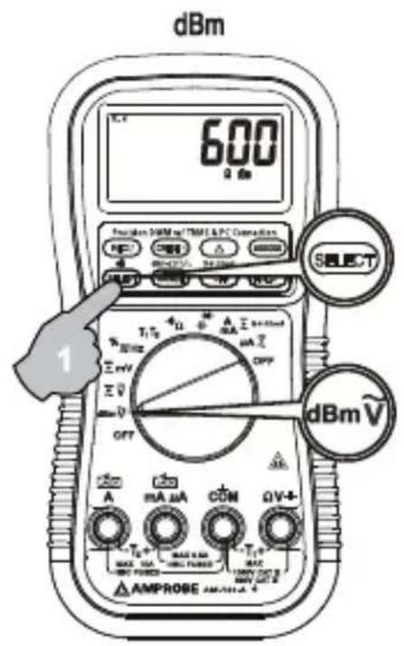
In AC Voltage, press SELECT button momentarily to toggle between AC and dBm. In DC Voltage, press SELECT button momentarily to toggle between DC, and DC+AC. In mV Voltage, press SELECT button momentarily to select DC, AC, or DC+AC. The new settings will be saved automatically to the nonvolatile memory as power up default. In DCV and DCmV, press 500000 button momentarily to toggle between 4-4/5 digits and 5-4/5 digits readings. In voltage or current functions, press the Hz push button momentarily to activate or to exit Line Level Frequency measuring function. Line Level Frequency measuring function is designed especially for noisy electrical high voltage signals.
Note: In dBm function, power up default reference impedance will be displayed for 1 second before displaying the dBm readings. Press dBm- (RANGE) button momentary to select different reference impedance of 4, 8, 16, 32, 50, 75, 93, 110, 125, 135, 150, 200, 250, 300, 500, 600, 800, 900, 1000, up to 1200 . The new impedance value will be saved automatically to the non-volatile memory as power up default.
text_image
dBm 600 Ω 5Ω Amplifier DMM to T/PMF & PC Connection SELECT 1 T1/T2 4Ω A EA DC OFF mA MAX MAX 5.0A MAX 5.0A MAX 5.0A MAX 5.0A AMPROSE AM/PGM A 4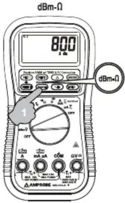
text_image
dBm-Ω 800 1 gm Production DMM and TRMC & TC Connection dBm-Ω 1 OFF A MA HA COM QV+1 T1+ MAX HA MAX PUMED T1+ MAX AMP AMPROSE AMPROSE+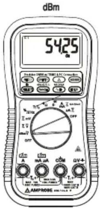
text_image
dBm 5425 Production GMN on TIMI & PC Connection OFF MAX 1000000000000000000000000000000000000000000000000000000000000000000000000 A mA μA COM ΩV+ AMPROBE AMPROBE
text_image
DCV 500000 500000 1 mA μA COM QV-11 AMPROSE AM +
text_image
ACV 2200 1 Pre-Action DMR at TMGL & FC Connection T1 T2 mA OFF A mA μA COM QV-4 AMPROSE AMP AMP AMP CAT ~ V ~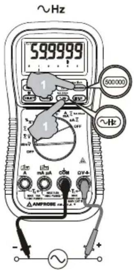
text_image
~Hz 599999 1 500000 ~Hz 1 mA μA COM QV-4 AMPROBE AM - ~+Note: Line Level Frequency measuring function input sensitivity varies automatically with voltage (or current) function range selected. The lower the measuring range the higher the sensitivity. That is, mV function has the highest and the 1000V range has the lowest as in voltage function ranges. It is recommended to first measure the signal voltage (or current) level then activate the Hz function in that voltage (or current) range to automatically get the most appropriate trigger level. When activated from voltage function, you can also press the RANGE button momentarily to select another trigger level range manually. The analog bargraph pointer will point at the selected trigger level range scale 1, 2, 3, or 4. If the Hz reading is unstable, select lower sensitivity to avoid electrical noise. If the reading shows zero, select higher sensitivity.
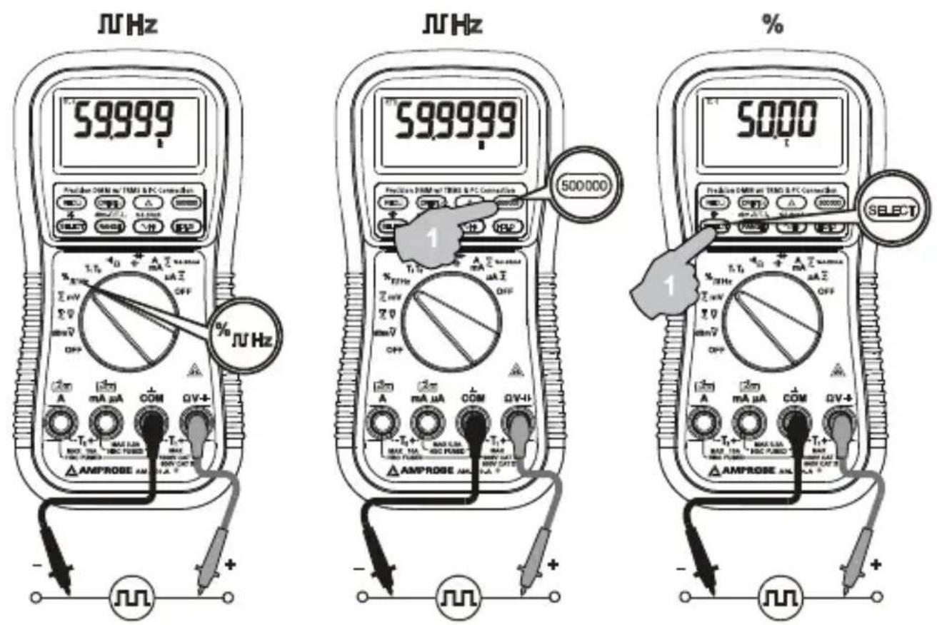
Hz Logic Level Frequency and % Duty Cycle functions
Press SELECT button momentarily to toggle between Hz and % (duty cycle) readings. The new setting will be saved automatically to the non-volatile memory as power up default. Press 500000 button momentarily to toggle between 5 full digits and 6 full digits Hz readings.
text_image
59999 59999 50000 50000 Select AmPROSE AM AmPROSE AM AMPROSE AM AmPROSE AM AmPROSE AM AmPROSE AM AmPROSE AM AmPROSE AM AmPROSE AM AmPROSE AM AmPROSE AM AmPROSE AM AmPROSE AM AmPROSE AM AmPROSE AM AmPROSE AM AmPROSE AM AmPROSE AM AmPROSE AM AmPROSE AM AmPROSE AM AmPROSE AM AmPROSE AM AMPROSE AM AmPROSE AM AmPROSE AM AmPROSE AM AmPROSE AM AmPROSE AM AmPROSE AM AmPROSE AM AmPROSE AM AmPROSE AM AmPROSE AM AmPROSE AM AmPROSE AM AmPROSE AM AmPROSE AM AmPROSE AM AmPROSE AM AmPROSE Am AmPROSE Am AmPROSE Am AmPROSE Am AmPROSE Am AmPROSE Am AmPROSE Am AmPROSE Am AmPROSE Am AmPROSE Am AmPROSE Am AmPROSE Am AmPROSE Am AmPROSE Am AmPROSE Am AmPROSE Am AmPROSE Am AmPROSE Am AmPROSE Am AmPROSE Am AmPROSE A M U A U A U A U A U A U A U A U A U A U A U A U A U A U A U A U A U A U A U A U A U A U A U A U A U A U A U A U A U A U A U A U A U A U A U A U A U A U A U A U A U A U A U A U A U A U A U A U A U A U A U U A U A U A U A U A U A U A U A U A U A U A U A U A U A U A U A U A U A U A U A U A U A U A U A U A U A U A U A U A U A U A U A U A U A U A U A U A U A U A U A U A U A U A U A U A U A U A U A U A UNote: Unlike the Line Level Frequency measuring function as previously stated, this Logic Level Frequency function is set only at the highest input sensitivity for measuring digital type electronic signals.
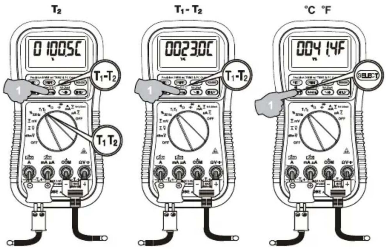
T1-T2 Dual Channels Temperature function (AM-160-A only)
Press SELECT button momentarily to toggle between °C and °F readings, and the new setting will be saved automatically in the non-volatile memory as power up default. Press T1-T2 (RANGE) button momentarily to select T1, T2, or T1-T2 readings.
Note: Insert the banana plug K-type temperature bead probe with correct + - polarities. Dual channels T1-T2 readings require 2 probes. You can also use a plug adapter (Optional purchase) with banana pins to K-type socket to adapt other standard K type mini plug temperature probes.
text_image
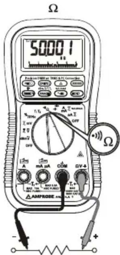
T₂ 0 100.5°C T₁-T₂ T₁-T₂ T₁-T₂ T₁-T₂ T₁-T₂ T₁-T₂ T₁-T₂ T₁-T₂ T₁-T₂ T₁-T₂ T₁-T₂ T₁-T₂ T₁-T₂ T₁-T₂ T₁-T₂ T₁-T₂ T₁-T₂ T₁-T₂ T₁-T₂ T₁-T₂ T₁-T₃ 00230°C T₃ 004 14F T₃ 004 14F T₃ 004 14F T₃ 004 14F T₃ 004 14F T₃ 004 14F T₃ 004 14F T₃ 004 14F T₃ 004 14F T₄ 00230°C T₄ 004 14F T₄ 004 14F T₄ 004 14F T₄ 004 14F T₄ 004 14F T₄ 004 14F T₄ 004 14F T₅ 00230°C T₅ 004 14F T₅ 004 14F T₅ 004 14F T₅ 004 14F T₅ 004 14F T₆ 00230°C T₆ 004 14F T₆ 004 14F T₆ 004 14F T₆ 004 14F T₇ 00230°C T₇ 004 14F T₇ 004 14F T₇ 004 14F T₇ 004 14F T₈ 00230°C T₈ 004 14F T₈ 004 14F T₈ 004 14F T₈ 004 14FΩ Resistance, • continuity functions
Press SELECT button momentarily to toggle between and •••• Continuity functions. The new setting will be saved automatically to the non-volatile memory as power up default. Continuity function is convenient for checking wiring connections and operation of switches. A continuous beep tone indicates a complete wire.
text_image
Ω 5000Ω Pre-2000/1MHz or TRM & PC Connection OFF T1/T2 mA Σ 27 MHz 2.0 V min/2 OFF A mA μA COM GV-4 AMPROSE AM MAX 1.5A MAX 1.5A MAX 1.5A MAX 1.5A MAX 1.5A MAX 1.5A MAX 1.5A MAX 1.5A MAX 1.5A MAX 1.5A MAX 1.5A MAX 1.5A MAX 1.5A MAX 1.5A MAX 1.5A MAX 1.5A MAX 1.5A MAX MAX 1.5A MAX MAX 1.5A MAX MAX 1.5A MAX MAX 1.5A MAX MAX 1.5A MAX MAX 1.5A MAX MAX 1.5A MAX MAX 1.5A MAX MAX 1.5A MAX MAX 1.5A MAX MAX 1.5A MAX MAX 1.5A MAX MAX 2.0 A MAX 2.0 A MAX 2.0 A MAX 2.0 A MAX 2.0 A MAX 2.0 A MAX 2.0 A MAX 2.0 A MAX 2.0 A MAX 2.0 A MAX 2.0 A MAX 2.0 A MAX 2.0 A MAX 2.0 A MAX 2.0 A AMPROSE AM
text_image
000.12 Prelimiter OMM m/ TMSI & PC Counter Set REC CREF Δ OFF Select 1 A mA μA COM QV-4- AMPROSE AM T1+ MAX 5Ω MAX 3Ω MAX 2Ω MAX 1Ω MAX 0.5Ω MAX 0.2Ω MAX 0.1Ω MAX 0.05Ω MAX 0.02Ω MAX 0.01Ω MAX 0.005Ω MAX 0.002Ω MAX 0.001Ω MAX 0.0005Ω MAX 0.0002Ω MAX 0.0001Ω MAX 0.00005Ω MAX 0.00002Ω MAX 0.00001Ω MAX 0.000005Ω MAX 0.000002Ω MAX 0.000001Ω MAX 0.0000005Ω MAX 0.0000002Ω MAX 0.0000001Ω MAX 0.00000005Ω MAX 0.00000002Ω MAX 0.00000001Ω MAX 0.000000005Ω MAX 0.000000002Ω MAX 0.000000001Ω MAX 0.0000000005Ω MAX 0.0000000002Ω MAX 0.0000000001Ω MAX 0.00000000005Ω MAX 0.00000000002Ω MAX 0.00000000001Ω MAX 0.00000000CAUTION
Using resistance or continuity function in a live circuit will produce false results and may damage the meter. In many cases the suspected component must be disconnected from the circuit to obtain an accurate reading.
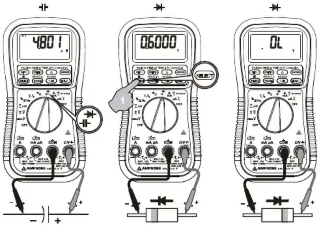
Capacitance, Diode test function
Press SELECT button momentarily to toggle between CAPacitance and Diode test functions. The new setting will be saved automatically to the non-volatile memory as power up default.
CAUTION
Discharge capacitors before making any measurement. Large value capacitors should be discharged through an appropriate resistance load.
text_image
480 l AmPROSE AMPROSE T1 T2 mA μA CON QV-4- Δ AmPROSE AMPROSE 06000 V AmPROSE AMPROSE 0L AmPROSE AMPROSE AmPROSE AMPROSE Select 1 AmPROSE AMPROSE AmPROSE AMPROSE AmPROSE AMPROSE AmPROSE AMPROSE AmPROSE AMPROSE AmPROSE AMPROSE AmPROSE AMPROSE AmPROSE AMPROSE AmPROSE AMPROSE AmPROSE AMPROSE AmPROSE AMPROSE AmPROSE AMPROSE AmPROSE AMPROSE AmPROSE AMPROSE AmPROSE AMPROSE AMPROSE AMPROSE AmPROSE AMPROSE AmPROSE AMPROSE AmPROSE AMPROSE AmPROSE AMPROSE AmPROSE AMPROSE AmPROSE AMPROSE AmPROSE AMPROSE AmPROSE AMPROSE AmPROSE AMPROSE AmPROSE AMPROSE AmPROSE AMPROSE AmPROSE AMPROSE AmPROSE AMPROSE AmPROS AMPROS AmPROS AMPROS AmPROS AMPROS AmPROS AMPROS AmPROS AMPROS AmPROS AMPROS AmPROS AMPROS AmPROS AMPROS AmPROS AMPROS AmPROS AMPROS AmPROS AMPROS AmPROS AMPROS AmPROS AMPROS AmPROS AMPROS AmPROS AMPROS ampros. 100000 V mV 300000 V mV 500000 V mV 700000 V mV 900000 V mV 1100000 V mV 1300000 V mV 1500000 V mV 1700000 V mV 1900000 V mV 2100000 V mV 2300000 V mV 2500000 V mV 2700000 V mV 2900000 V mV 3100000 V mV 3300000 V mV 3500000 V mV 3700000 V mV 3900000 V mV 4100000 V mV 4300000 V mV 4500000 V mV 4700000 V mV 4900000 V mV 5100000 V mV 5300000 V mV 5500000 V mV 5700000 V mV 5900000 V mV 6100000 V mV 6300000 V mV 6500000 V mV 6700000 V mV 6900000 V mV 7100000 V mV 7300000 V mV 7500000 V mV 7700000 V mV 7900000 V mV 8100000 V mV 8300000 V mV 8500000 V mV 8700000 V mV 8900000 V mV 910Note: Normal forward voltage drop (forward biased) for a good silicon diode is between 0.400V to 0.900V. A reading higher than that indicates a leaky diode (defective). A zero reading indicates a shorted diode (defective). An OL indicates an open diode (defective). Reverse the test leads connections (reverse biased) across the diode. The digital display shows OL if the diode is good. Any other readings indicate the diode is resistive or shorted (defective).
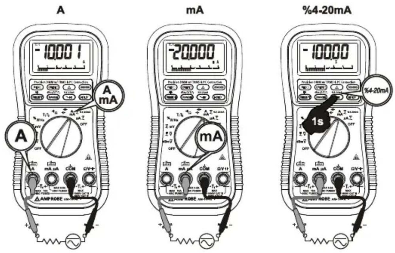
μA, mA, A, and %4-20mA Current functions
Insert the red test lead into the correct A/mA or A input jack. Press SELECT button momentarily to select DC, AC, or DC+AC. The new settings will be saved automatically to the non-volatile memory as power up default. In DC mA function, neither in AC nor in DC+AC, press and hold the \%4-20mA ( Hz) button for 1 second or more to display the current digital data in terms of loop current percentage (%) value. It is set at 4mA = 0% (zero) and 20mA = 100% (span) with 0.01% high resolution, which virtually extends the meters' capability to test and regulate the externally powered loop current in the industrial process control applications. The analog bar-graph remains showing the mA current value to alert the user.
⚠ Warning
When measuring a 3-phase system, special attention should be taken to the phase-to-phase voltage that is significantly higher than the phase-to-earth voltage. To avoid exceeding the voltage rating of the protection fuse(s) accidentally, always consider the phase-to-phase voltage as the working voltage for the protection fuse(s).
PC-COMM computer interface capabilities
The instrument equips with an optical isolated interface port at the meter back for data communication. Optional purchase PC interface kit USB-KIT3 is required to connect the meter to the PC computer. The USB-KIT3 Data Recording System software equips with a digital meter, an analog meter, a comparator meter, and a Data Graphical recorder display. Refer to the README file in the interface kit for further details.
MAX/MIN RECORDING mode
Press REC button momentarily to activate MAX/MIN recording mode. The LCD annunciators "R" and "MAX MIN" turn on. The meter beeps when new maximum or minimum reading is updated. Press the button momentarily to read throughout the Maximum (MAX), Minimum (MIN), and Maximum minus Minimum (MAX-MIN) readings. Press the button for 1 second or more to exit MAX/MIN recording mode. Auto Power Off feature will be disabled automatically in this mode.
CREST Capture (Instantaneous Peak Hold) mode
Press CREST button momentarily to activate CREST mode to capture voltage or current signal duration as short as 0.8ms. This mode is available in DC, AC, DC+AC modes of voltage and current functions. The LCD annunciators "C" & "MAX" turn on. The meter beeps when new maximum or minimum reading is updated. Press the button momentarily to read throughout the Maximum (MAX), Minimum (MIN), and Maximum minus Minimum (MAX-MIN) readings. Press the button for 1 second or more to exit CREST capture mode. Auto Power Off feature will be disabled automatically in this mode.
Relative Zero mode
Relative Zero allows the user to offset the meter consecutive measurements with the displaying reading as the reference value. Practically MAX/MIN recording feature readings can also be set as relative reference value. Press the ▲ button momentarily to activate and to exit Relative Zero mode.
500000 high resolution stable mode
In DC voltage and frequency functions, press the 500000 button momentarily to toggle between the 4-4/5 digits fast mode and the 5-4/5 digits high resolution stable mode.
Backlighted display
Press the SELECT button for 1 second or more to turn on or off the display backlight function. It will also be turned off automatically after 30 seconds to extend battery life.
Manual or Auto-ranging
Press the RANGE button momentarily to select manual-ranging mode, and the meter will remain in the range it was in, the LCD annunciator AUTO turns off. Press the button momentarily again to step through the ranges. Press and hold the button for 1 second or more to resume auto-ranging mode.
Note: Manual ranging mode feature is not available in Hz function.
Hold H
The hold function freezes the display for later view. Press the HOLD H button momentarily to activate or to exit the hold function.
Set Beeper Off
Press the Hz button while turning the meter on to disable the push button operating beeper feature. However, the continuity and Jack Beep input warning features remain.
Beep-Jack™ Input Warning
The meter beeps as well as displays "InErr" to warn the user against possible damage to the meter due to improper connections to the A, mA, or A input jacks when other function (like voltage function) is selected.
Intelligent Auto Power Off (APO)
The Intelligent Auto Power Off (APO) mode turns the meter off automatically to extend battery life after approximately 17 minutes of no activities. Activities are specified as: 1) Rotary switch or push button operations, and 2) Significant measuring readings of above 10% of range or non-OL Ω readings. In other words, the meter will intelligently avoid entering the APO mode when it is under normal measurements. To wake up the meter from APO, press the RECORD button momentarily or turn the rotary switch to the OFF position and then turn back on again. Always turn the rotary switch to the OFF position when the meter is not in use.
Disabling Auto Power Off
Press the RANGE button while turning the meter on to disable the Auto Power Off (APO) feature.
General Specifications
Display: 4-4/5 digits 50,000 counts. Selectable stable
mode 5-4/5 digits 500,000 counts for DC
voltage,& 6 digits 999,999 counts for HZ
Polarity: Automatic
Update rate:
4-4/5 digits fast mode: 5 per second nominal;
5-4/5 digits stable mode:1.25 Per second
nominal;
42 Segments bar graph: 60 per second max
Operating temperature: 0°C to 45°C (32°F to 113°F)
Relative humidity: Maximum relative humidity 80% for
temperature up to 31°C decreasing linearly to
50% relative humidity at 45°C
Pollution degree: 2
Storage temperature: -20^ to 60^ ( -4^ to 140^ ), <80% R.H.
(With battery removed)
Altitude: Operating below 2000m
Temperature coefficient: Nominal 0.1 X (specified accuracy)/ °C @ (0°C -
18^ or 28^ -- 40^/32^ - 104^ ), or otherwise specified
Sensing: AC, AC+DC true RMS
Safety: Double insulation per iec61010-1 2nd ed.,
En61010-1 2nd ed., Ul61010-1 2nd ed. & Can/csa
c22.2 No. 61010.1-0.92 To category III 1000v AC
& DC and category IV 600V AC & DC
Am-140-a terminals (to COM) measurement category:
V : Category III 1000 VAC & VDC and category iv 600 VAC & VDC.
A / mAμA: Category III and category iv 600 VAC and 300 VDC.
Am-160-a terminals (to COM) measurement category:
V / A / mAμA: Category III 1000 VAC & VDC and category IV 600 VAC & VDC.
Overload protections:
Am-140-a:
μA & mA: 1A/600V, IR 10kA or better, F fuse
A: 10A/600V, IR 100kA or better, F fuse
V: 1050VRMS, 1450VPEAK
mV, Ω, & others: 600 VDC & VAC RMS
Am-160-a:
μA & mA: 0.44A/1000V, IR 10kA or better, F fuse
A: 11A/1000V, IR 20kA or better, F fuse
V, mV, Ω, & others: 1050VRMS, 1450VPEAK
Transient protection: 8kV (1.2/50μS SURGE)
E.M.C.: Meets en61326-1:2006 (EN55022, EN61000-3-
2, EN61000-3-3, EN61000-4-2, EN61000-4-3,
EN61000-4-4, , EN61000-4-5, EN61000-4-6,
EN61000-4-8, EN61000-4-11)
In an RF field of 3V/m: Capacitance function is not specified
Other function ranges: Total accuracy = specified accuracy + 100 digits.
Performance above 3V/m is not specified
Power supply: Single alkaline 9V battery; neda1604a, jis6am6
or lec6lf22
Power consumption: 6mA typical
Low battery: Below approx. 7V
Apo timing: Idle for 17 minutes
Apo consumption: 55μA typical for am-140-a; 30μA typical for am-
160-a
Dimension: L186mm x W87mm x H35.5mm (7.3in x 3.4in
x 1.4in); L198mm x W97mm x H55mm (7.8in x
3.8in x 2.2in) with holster
Weight: 390 gm (0.9lb); 500 gm (1.1lb) with holster
Electrical Specifications
Accuracy is ± % reading digits + number of digits) or otherwise specified, at 23^ ± 5^ & less than 75% relative humidity.
True rms voltage & current accuracies are specified from 5 % to 100 % of range or otherwise specified. maximum crest factor < 5:1 at full scale & < 10:1 at half scale, and with frequency components within the specified frequency bandwidth for non-sinusoidal waveforms.
DC Voltage
| Range AM-160-A AM-140-A | ||
| Accuracy | ||
| 500.00 MV, 5.0000V, 50.000V | 0.02% + 2D 0.03% | + 2D |
| 500.00V 0.04%+2D | 0.05% + 2D | |
| 1000.0V 0.05%+2D | 0.1%+2D | |
NMRR: >60DB @ 50/60HZ
CMRR: >120DB @ DC, 50/60HZ, RS=1KΩ
Input Impedance: 10MΩ, 30pF nominal (80pF nominal for 500mV range)
Ohms
| Range AM-160-A AM-140-A | ||
| Accuracy | ||
| 500.00Ω 0.07%+ | 10D | 0.1%+6D |
| 5.0000KΩ | 0.07%+2D50.000KΩ | |
| 500.00KΩ | ||
| 5.0000MΩ 0.2%+ | 6D 0.4%+6D | |
| 50.000MΩ 2.0%+ | 6D 2.0%+6D | |
Open Circuit Voltage: < 1.3VDC (< 3VDC FOR 500Ω RANGE)
PAC & AC+DC Voltage
| Range AM-160-A | AM-140-A | |
| Accuracy* | ||
| 20HZ -- 45HZ | ||
| 500.00MV, 5.0000V, 50.000V | 1.5% + 60D | UNSPEC'D |
| 500.00V, 1000.0V UNSPEC'D | ||
| 45HZ -- 300HZ | ||
| 500.00MV 0.3% + | 20D | 0.8%+60D5.0000V, 50.0 |
| 500.00V,1000.0V 0.4% | + 40D | |
| 300HZ -- 5KHZ 300HZ | -- 1KHZ | |
| 500.00MV 0.3% + | 10D 0.8%+40D | |
| 5.0000V, 50.000V, 500.00V | 0.4% + 40D 2.0%+60D | |
| 1000.0V | 0.8% + 40D(300HZ--1KHZ) | 1.0%+40D |
| 5KHZ -- 20KHZ 1KHZ | -- 20KHZ | |
| 500.00MV 0.5%+20D 1DB** | ||
| 5.0000V, 50.000V 0.8%+20D 2DB** | ||
| 500.00V 0.5%+20D 3DB** | ||
| 1000.0V UNSPEC'D UNSPEC'D | ||
| 20KHZ -- 100KHZ | ||
| 500.00MV 2.5%+40D | ||
| 5.0000V, 50.000V 4.0% | +40D** | |
| 500.00V | UNSPEC'D | |
| 1000.0V | ||
*from 5% to 10% of range: accuracy % of reading (or in db) + 80d
**from 5% to 10% of range: accuracy % of reading (or in db) + 180d
**from 10% to 15% of range: accuracy % of reading (or in db) + 100d
cmrr: >80db @ dc to 60hz, rs=1kΩ
input impedance: 10mΩ 30pf nominal (80pf nominal for 500mv range) residual reading less than 50 digits with test leads shorted.
DBM: at 600Ω, -11.76dbm to 54.25dbm
accuracy: ± 0.25db + 2d (@40hz -- 20khz)
input impedance: 10mΩ, 30pf nominal
selectable reference impedance of 4, 8, 16, 32, 50, 75, 93, 110, 125, 135, 150, 200, 250, 300, 500, 600, 800, 900, 1000, 1200Ω
• ) ) ) AUDIBLE CONTINUITY TESTER
Audible threshold: between 20Ω and 200Ω response time < 100μS

Diode Tester
| Range Accuracy | Test Current (Typical) | Open Circuit Voltage |
| 5.0000V 1%+1D 0.4mA < 3.5 VDC |
Capacitance
| Range Accuracy* | |
| 50.00nF 0.8% + 3D | |
| 500.0nF 0.8% + 3D | |
| 5.000μF 1.5% + 3D | |
| 50.00μF 2.5% + 3D | |
| 500.0μF** 3.5% + 5D | |
| 9999μF** 5.0% + 5D |
*accuracies with film capacitor or better
**in manual-ranging mode, measurements not specified below 45.0μF and 450μF for 500.0μF and 9999μF ranges respectively
DC Current
| Range Accuracy | Burden Voltage | |
| 500.00μA 0.15%+20D 0.15mV/μA | ||
| 5000.0μA 0.1%+20D 0.15mV/μA | ||
| 50.000mA 0.15%+20D 3.3mV/mA | ||
| 500.00mA 0.1%+30D 3.3mV/mA | ||
| 5.0000A 0.5%+20D 45mV/A | ||
| 10.000A* 0.5%+20D 45mV/A | ||
*10A continuous, >10A to 15A (TO 20A for AM-160-A) for 30 second max with 5 minutes cool down interval
AC & AC+DC Current
| Range | AM-160-A AM-140-A | Burden Voltage | |
| Accuracy | |||
| 50HZ -- 60HZ | |||
| 500.00μA | mV/μA0.5%+50D 1.0%+40D | 0.15mV/μA | |
| 5000.0μA 0.15mV/mA | |||
| 50.000mA 3.3mV/mA | |||
| 500.00mA 3.3mV/mA | |||
| 5.0000A | 45mV/A | ||
| 10.000A* | 45mV/A | ||
| 40HZ - 1KHZ | |||
| 500.00μA | mV/μA0.7%+50D 1.0%+40D | 0.15mV/μA | |
| 5000.0μA 0.15mV/mA | |||
| 50.000mA 3.3mV/mA | |||
| 500.00mA 3.3mV/mA | |||
| 5.0000Å | 45mV/A | ||
| 10.000Å* | 45mV/A | ||
| 1KHZ – 10KHZ | |||
| 500.00μA | mV/μA2.0%+50D UNSPEC'D | SPEC'D | 0.15mV/μA |
| 5000.0μA 0.15 | |||
| 50.000mA 3.3mV/mA | |||
| 500.00mA 3.3mV/mA | |||
| 5.0000A10.000A* | UNSPEC'D UNSPEC'D 45mV/A | ||
*10A continuous, >10A to 15A (to 20A FOR AM-160-A) for 30 second max with 5 minutes cool down interval
DC LOOP CURRENT %4--20MA
4mA = 0% (zero)
20mA = 100% (span)
Resolution: 0.01%
Accuracy: ± 25D
Crest mode (Instantaneous Peak Hold)
Accuracy: specified accuracy ± 100 digits for changes > 0.8ms in duration
T1-T2 Dual Temperature (AM-160-A only)
| Range Accuracy | |
| -50.0°C TO 1000.0°C 0.3%+1°C | |
| -58.0°F TO 1832.0°F 0.3%+2°F |
Thermocouple range & accuracy not included
\~ Hz Line Level Frequency
| Function Range Sensitivity(Sine Rms) | Range | |
| 500mV 100mV 10HZ ~ 200KHZ | ||
| 5V 1V 10HZ ~ 200KHZ | ||
| 50V 10V 10HZ ~ 100KHZ | ||
| 500V 100V | 10HZ ~ 100KHZ | |
| 1000V 900V 10HZ ~ 10KHZ |
Accuracy: 0.02%+4d
Hz Logic Level Frequency
| Range Accuracy | |
| 5.0000HZ--2.00000MHZ 0.002% | +4D |
Sensitivity: 2.5VP square wave
%DUTY CYCLE
| Range Accuracy | |
| 0.1% -- 99.99% 3D/KHZ+2D |
Input frequency: 5HZ -- 500 KHZ, 5V logic family
MAINTENANCE AND REPAIR
WARNING
To avoid electrical shock, disconnect the meter from any circuit, remove the test leads from the input jacks and turn OFF the meter before opening the case. Do not operate with open case. Install only the same type of fuse or equivalent
Calibration
Periodic calibration at intervals of one year is recommended to maintain meter accuracy. Accuracy is specified for a period of one year after calibration.
If self-diagnostic message "rE-O" is being displayed while powering on, the meter is re-organizing internal parameters. Do not switch off the meter then, and it will be back to normal measurement shortly. However, if self-diagnostic message "C_Er" is being displayed while powering on, some meter ranges might be largely out of specifications. To avoid mis-leading measurements, stop using the meter and send it for re-calibration. Refer to the LIMITED WARRANTY section for obtaining warranty or repairing service.
Trouble Shooting
If the instrument fails to operate, check battery, fuses, leads, etc., and replace as necessary. Double check operating procedure as described in this user's manual. If the instrument voltage-resistance input terminal has subjected to high voltage transient (caused by lightning or switching surge to the system) by accident or abnormal conditions of operation, the series fusible resistors will be blown off (become high impedance) like fuses to protect the user and the instrument. Most measuring functions through this terminal will then be open circuit. The series fusible resistors and the spark gaps should then be replaced by qualified technician. Refer to the LIMITED WARRANTY section for obtaining warranty or repairing service.
Cleaning and Storage
Periodically wipe the case with a damp cloth and mild detergent; do not use abrasives or solvents. If the meter is not to be used for periods of longer than 60 days, remove the battery and store it separately.
Battery and Fuse Replacement
Battery use:
9V alkaline battery NEDA1604A, JIS6AM6 or IEC6LF22
AM-140-A
Fuse (FS1) for AmA current input: 1A/600V, IR 10kA or better, F fuse; Fuse (FS2) for A current input: 10A/600V, IR 100kA or better, F fuse
AM-160-A
Fuse (FS1) for AmA current input: 0.44A/1000V, IR 10kA or better, F fuse Fuse (FS2) for A current input: 11A/1000V, IR 20kA or better, F fuse
Battery replacement for models with battery access door:
Loosen the 2 screws from the battery access door of the case bottom. Lift the battery access door and thus the battery compartment up. Replace the battery. Re-fasten the screws.
Fuse replacement:
Loosen the 4 screws from the case bottom. Lift the end of the case bottom nearest the input jacks until it unsnaps from the case top. Replace the blown fuse(s) and/or the battery. Replace the case bottom, and ensure that all the gaskets are properly seated and the two snaps on the case top (near the LCD side) are engaged. Re-fasten the screws.

natural_image
Technical line drawing of a multi-functional electronic device with labeled ports (no text or symbols beyond component labels)Visit www.Amprobe.com for
- Catalog
- Application notes
• Product specifications - User manuals