PXGMTK-4182 - Hedge Trimmer Ozito - Free user manual and instructions
Find the device manual for free PXGMTK-4182 Ozito in PDF.


| Product Type | Hedge Trimmer |
| Brand | Ozito |
| Model | PXGMTK-4182 |
| Power Source | 18V Battery (Power X Change compatible) |
| Cutting Action | Dual-action blades |
| Blade Length | 51 cm (20 inches) |
| Tooth Spacing | 20 mm |
| Maximum Cut | 20 mm branches |
| Weight (without battery) | 2.7 kg |
| Overall Length | 94 cm |
| Handle Design | 360° rotating rear handle |
| Safety Features | Two-handed switch, blade guard |
| Vibration Isolation | Soft grip handle |
| Battery Voltage | 18 V |
| Battery Capacity (typical) | 2.0 Ah (sold separately) |
| Charging Time (2.0 Ah) | 1.5 hours |
| Run Time (2.0 Ah) | Up to 45 minutes |
| Blade Material | Hardened steel |
| Maintenance | Clean blades after use, oil regularly |
Frequently Asked Questions - PXGMTK-4182 Ozito
User questions about PXGMTK-4182 Ozito
0 question about this device. Answer the ones you know or ask your own.
Ask a new question about this device
Download the instructions for your Hedge Trimmer in PDF format for free! Find your manual PXGMTK-4182 - Ozito and take your electronic device back in hand. On this page are published all the documents necessary for the use of your device. PXGMTK-4182 by Ozito.
USER MANUAL PXGMTK-4182 Ozito
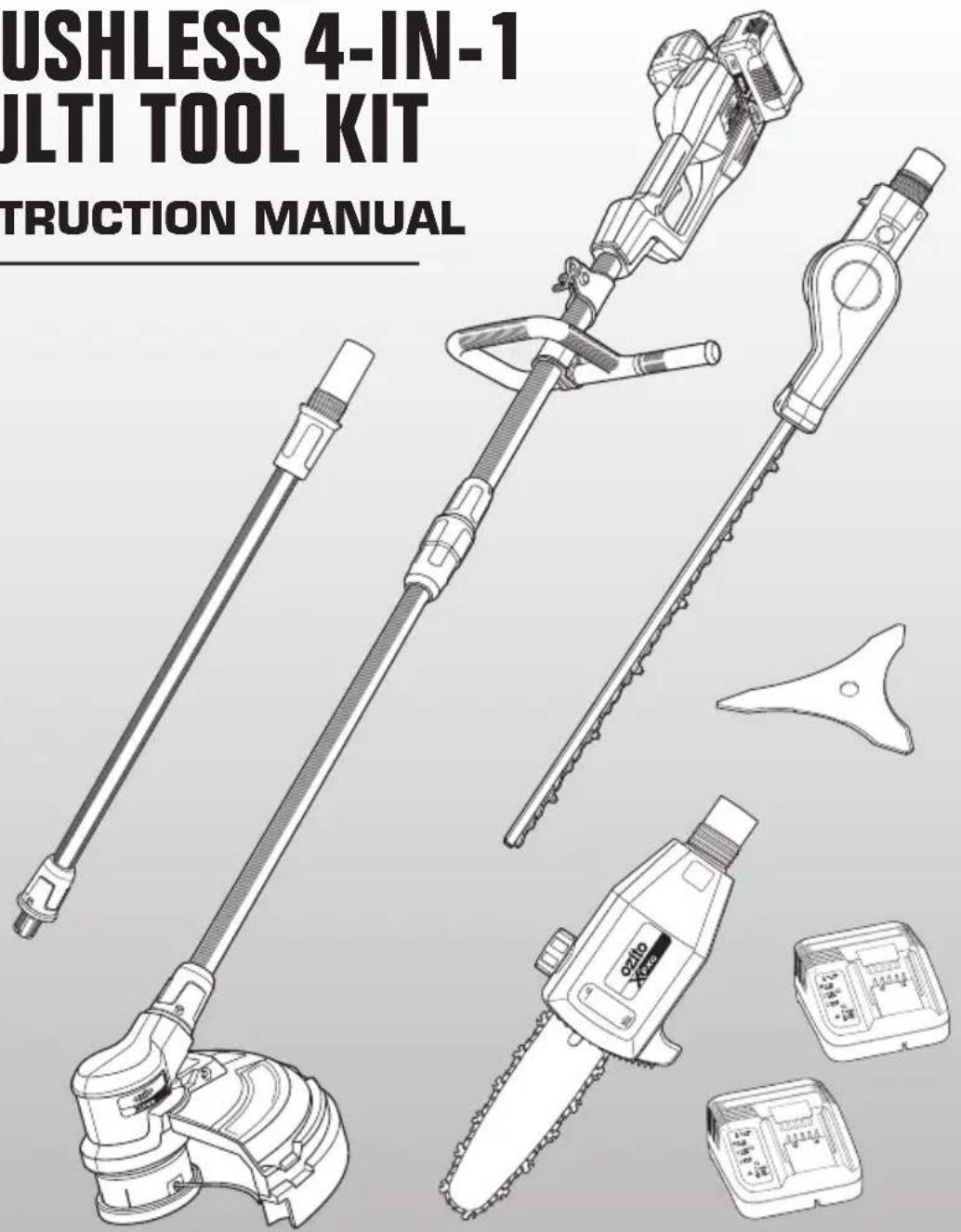
BRUSHLESS 4-IN-1 MULTI TOOL KIT
INSTRUCTION MANUAL

GENERAL POWER TOOL SAFETY WARNINGS

WARNING! Read all safety warnings and all instructions. Failure to follow the warnings and instructions may result in electric shock, fire and/or serious injury.
Save all warnings and instructions for future reference. The term "power tool" in the warnings refers to your mains-operated (corded) power tool or battery-operated (cordless) power tool.
1. Work area safety
a. Keep work area clean and well lit. Cluttered or dark areas invite accidents.
b. Do not operate power tools in explosive atmospheres, such as in the presence of flammable liquids, gases or dust. Power tools create sparks which may ignite the dust or fumes.
c. Keep children and bystanders away while operating a power tool. Distractions can cause you to lose control.
2. Electrical safety
a. Power tool plugs must match the outlet. Never modify the plug in any way. Do not use any adapter plugs with earthed (grounded) power tools. Unmodified plugs and matching outlets will reduce risk of electric shock.
b. Avoid body contact with earthed or grounded surfaces, such as pipes, radiators, ranges and refrigerators. There is an increased risk of electric shock if your body is earthed or grounded.
c. Do not expose power tools to rain or wet conditions. Water entering a power tool will increase the risk of electric shock.
d. Do not abuse the cord. Never use the cord for carrying, pulling or unplugging the power tool. Keep cord away from heat, oil, sharp edges or moving parts. Damaged or entangled cords increase the risk of electric shock.
e. When operating a power tool outdoors, use an extension cord suitable for outdoor use. Use of a cord suitable for outdoor use reduces the risk of electric shock.
f. If operating a power tool in a damp location is unavoidable, use a residual current device (RCD) protected supply. Use of an RCD reduces the risk of electric shock.
3. Personal safety
a. Stay alert, watch what you are doing and use common sense when operating a power tool. Do not use a power tool while you are tired or under the influence of drugs, alcohol or medication. A moment of inattention while operating power tools may result in serious personal injury.
b. Use personal protective equipment. Always wear eye protection. Protective equipment such as dust mask, non-skid safety shoes, hard hat, or hearing protection used for appropriate conditions will reduce personal injuries.
c. Prevent unintentional starting. Ensure the switch is in the off-position before connecting to power source and/or battery pack, picking up or carrying the tool. Carrying power tools with your finger on the switch or energising power tools that have the switch on invites accidents.
d. Remove any adjusting key or wrench before turning the power tool on. A wrench or a key left attached to a rotating part of the power tool may result in personal injury.
e. Do not overreach. Keep proper footing and balance at all times. This enables better control of the power tool in unexpected situations.
f. Dress properly. Do not wear loose clothing or jewellery. Keep your hair, clothing and gloves away from moving parts. Loose clothes, jewellery or long hair can be caught in moving parts.
g. If devices are provided for the connection of dust extraction and collection facilities, ensure these are connected and properly used. Use of dust collection can reduce dust-related hazards.
h. Do not let familiarity gained from frequent use of tools allow you to become complacent and ignore tool safety principles. A careless action can cause severe injury within a fraction of a second.
4. Power tool use and care
a. Do not force the power tool. Use the correct power tool for your application. The correct power tool will do the job better and safer at the rate for which it was designed.
b. Do not use the power tool if the switch does not turn it on and off. Any power tool that cannot be controlled with the switch is dangerous and must be repaired.
c. Disconnect the plug from the power source and/or the battery pack from the power tool before making any adjustments, changing accessories, or storing power tools. Such preventive safety measures reduce the risk of starting the power tool accidentally.
d. Store idle power tools out of the reach of children and do not allow persons unfamiliar with the power tool or these instructions to operate the power tool. Power tools are dangerous in the hands of untrained users.
e. Maintain power tools. Check for misalignment or binding of moving parts, breakage of parts and any other condition that may affect the power tool's operation. If damaged, have the power tool repaired before use. Many accidents are caused by poorly maintained power tools.
f. Keep cutting tools sharp and clean. Properly maintained cutting tools with sharp cutting edges are less likely to bind and are easier to control.
g. Use the power tool, accessories and tool bits etc. in accordance with these instructions, taking into account the working conditions and the work to be performed. Use of the power tool for operations different from those intended could result in a hazardous situation.
h. Keep handles and grasping surfaces dry, clean and free from oil and grease. Slippery handles and grasping surfaces do not allow for safe handling and control of the tool in unexpected situations.

GENERAL POWER TOOL SAFETY WARNINGS
5. Battery tool use and care
a. Recharge only with the charger specified by the manufacturer. A charger that is suitable for one type of battery pack may create a risk of fire when used with another battery pack.
b. Use power tools only with specifically designated battery packs. Use of any other battery packs may create a risk of injury and fire.
c. When battery pack is not in use, keep it away from other metal objects, like paper clips, coins, keys, nails, screws or other small metal objects, that can make a connection from one terminal to another. Shorting the battery terminals together may cause burns or a fire.
d. Under abusive conditions, liquid may be ejected from the battery; avoid contact. If contact accidentally occurs, flush with water. If liquid contacts eyes, additionally seek medical help. Liquid ejected from the battery may cause irritation or burns.
e. Do not use a battery pack or tool that is damaged or modified. Damaged or modified batteries may exhibit unpredictable behaviour resulting in fire, explosion or risk of injury.
f. Do not expose a battery pack or tool to fire or excessive temperature. Exposure to fire or temperature above 130^ C may cause explosion.
g. Follow all charging instructions and do not charge the battery pack or tool outside the temperature range specified in the instructions. Charging improperly or at temperatures outside the specified range may damage the battery and increase the risk of fire.
6. Service
a. Have your power tool serviced by a qualified repair person using only identical replacement parts. This will ensure that the safety of the power tool is maintained.
b. Never service damaged battery packs. Service of battery packs should only be performed by the manufacturer or authorized service provider.

LINE TRIMMER / BRUSH CUTTER SAFETY WARNINGS

WARNING! This appliance is not intended for use by persons (including children) with reduced physical, sensory or mental capabilities, or lack of experience and knowledge, unless they have been given supervision or instruction concerning use of the appliance by a person responsible for their safety.
Young children should be supervised to ensure that they do not play with the appliance.
- Never allow children or people unfamiliar with these instructions to use the line trimmer.
- Avoid using the line trimmer, while people, especially children or pets, are nearby.
- Use the line trimmer only in daylight or good artificial light.
- Maintain a safety distance of 15m. If approached, switch off the equipment immediately.
- Never operate the line trimmer with damaged guards or without guards in place.
- Switch on the line trimmer only when the hands and feet are away from the cutting head.
- Use only the manufacturer's recommended replacement parts and accessories.
- Disconnect the batteries from the line trimmer before carrying out maintenance or cleaning work.
- Inspect and maintain the line trimmer regularly. Have the line trimmer repaired only by an authorized repairer.
- Take care against injury from the blade(s) fitted for trimming the cutting line length. After extending new cutting line, always return the line trimmer to its normal operating position before switching on.
- Do not operate in a hazardous location. Such areas include where there is a risk of explosion of petrol fumes, leaking gas or explosive dust.
- Do not operate in a confined area. Exhaust gases, smoke or fumes could reach dangerous concentrations.
- Protect your tool. This line trimmer is NOT WEATHERPROOF and should not be exposed to direct sunlight, high ambient temperature and damp, wet or high humidity conditions.
- When not in use, store the line trimmer out of the reach of children.
- Face the cutting head away from yourself, other people and animals, especially during operation.
- Disconnect the batteries when changing spools or clearing grass from under the guard.
- Disconnect the batteries from the line trimmer before making any adjustments.
- Use both handles.
- Keep ventilation openings clear of debris. Keep handles dry, clean and free of oil and grease.
- When using the trimmer, stones, pieces of metal and other objects can be thrown out at high speed by the blade. The tool and guard are designed to reduce the danger. However, the following special precautions should be taken:
- Wear safety glasses or other eye protection, gloves, long pants and suitable footwear.
- Make sure that other people and pets are at least 5 metres away.
- Never reach underneath the line trimmer (the cutting line area) until it has completely stopped and the batteries have been disconnected.
- Never use a product that has been modified and always use original accessories.
- The blade can recoil suddenly from objects if it cannot cut or mow through them. This can cause injuries to the arms or legs. Keep bystanders and animals at least 15m away from where you are working. Always check the blade for signs of damage and replace the blade if it is bent or cracked.
- Carefully check your machine and its fittings for signs of damage every time before use. Do not use the equipment unless all the blade fittings are installed correctly.
- When you release the trigger lever, the blade will continue to rotate and will only gradually come to a standstill. A blade which is in the process of rotating to a standstill can cause you or bystanders injuries through cutting. Before you start any work on the blade, switch off the unit and ensure that the blade has come to a standstill.

WARNING! When servicing, use only identical replacement parts. Use of any other parts may create a hazard or cause product damage. To ensure safety and reliability, all repairs should be performed by a qualified service technician.

WARNING! This appliance is not intended for use by young or infirm persons unless supervised by a responsible person to ensure that they can use the appliance safely. Young children should be supervised to ensure that they do not play with the appliance.

WARNING! THE BLADE NUT (M10 SELF-LOCKING, LEFT-HAND THREAD) MUST NOT BE RE-USED. WHEN RE-INSTALLING THE BLADE, USE A NEW BLADE NUT. FAILURE TO FOLLOW THIS PROCEDURE CAN RESULT IN SERIOUS INJURY.

POLE HEDGE TRIMMER SAFETY WARNINGS
- Keep all parts of the body away from the cutter blade. Do not remove cut material or hold material to be cut when blades are moving. Make sure the switch is off when clearing jammed material. A moment of inattention while operating the hedge trimmer may result in serious personal injury.
- Carry the hedge trimmer by the handle with the cutter blade stopped. When transporting or storing the hedge trimmer always fit the cutting device cover. Proper handling of the hedge trimmer will reduce possible personal injury from the cutter blades.
- Hold the power tool by insulated gripping surfaces only, because the cutter blade may contact hidden wiring. Cutter blades contacting a "live" wire may make exposed metal parts of the power tool "live" and could give the operator an electric shock.
- Perform visual inspection on the hedge being trimmed. To ensure no wire fences or foreign objects that the hedge trimmer may contact during operation.
- Never allow children or people unfamiliar with these instructions to use the Hedge Trimmer.
- Avoid using the Hedge Trimmer, while people, especially children or pets, are nearby.
- Use the Hedge Trimmer only in daylight or good artificial light.
- Never operate the Hedge Trimmer with damaged guards or without guards in place.
- Switch on the Hedge Trimmer only when the hands and feet are away from the cutting blades.
- Use only the manufacturer's recommended replacement parts and accessories.
• Always remove the battery from the Hedge Trimmer when leaving the Hedge Trimmer unattended.
• Always remove the battery from the Hedge Trimmer before carrying out maintenance or cleaning work. - Inspect and maintain the Hedge Trimmer regularly. Have the Hedge Trimmer repaired only by an authorized repairer.
- When not in use, store the Hedge Trimmer out of the reach of children.
- Face the cutting blades away from yourself, other people and animals while the batteries are connected to the Hedge Trimmer (especially during operation).
- Use both handles.
- Keep ventilation openings clear of debris. Keep handles dry, clean and free of oil and grease.
- Do Not use if under influence of alcohol, drugs, medication or fatigue.
- Ensure regular breaks are taken if the task entails long duration time.
- Do not run while using hedge trimmer.
- Never operate the hedge trimmer in the rain or in wet conditions.
- Never modify or lock on/off trigger and safety switch on.
- Never reach underneath the Hedge Trimmer (the cutting blade area) until it has completely stopped and the power has been disconnected.

WARNING! When servicing, use only identical replacement parts. Use of any other parts may create a hazard or cause product damage. To ensure safety and reliability, all repairs should be performed by a qualified service technician.

WARNING! This appliance is not intended for use by young or infirm persons unless supervised by a responsible person to ensure that they can use the appliance safely. Young children should be supervised to ensure that they do not play with the appliance.

POLE PRUNER SAFETY WARNINGS

WARNING! This appliance is not intended for use by persons (including children) with reduced physical, sensory or mental capabilities, or lack of experience and knowledge, unless they have been given supervision or instruction concerning use of the appliance by a person responsible for their safety.
Young children should be supervised to ensure that they do not play with the appliance.
- Keep all parts of the body away from the saw chain when the chain saw is operating. Before you start the pruner, make sure the saw chain is not contacting anything. A moment of inattention while operating pruner may cause entanglement of your clothing or body with the pruner saw chain.
- Always hold the pruner with your right hand on the rear handle and your left hand on the front handle. Holding the pruner with a reversed hand configuration increases the risk of personal injury and should never be done.
- Wear safety glasses and hearing protection. Further protective equipment for head, hands, legs and feet is recommended. Adequate protective clothing will reduce personal injury by flying debris or accidental contact with the pruning saw chain.
- Do not operate a pruner in a tree. Operation of a pruner while up in a tree may result in personal injury.
- Always keep proper footing and operate the pruner only when standing on fixed, secure and level surface. Slippery or unstable surfaces such as ladders may cause a loss of balance or control of the pole pruner.
- When cutting a limb that is under tension be alert for spring back. When the tension in the wood fibres is released the spring loaded limb may strike the operator and/or throw the pole pruner out of control.
- Use extreme caution when cutting brush and saplings. The slender material may catch the pole pruner chain and be whipped toward you or pull you off balance.
- Carry the pole pruner by the front handle with the pole pruner switched off and away from your body. When transporting or storing the pole pruner always fit the guide bar cover. Proper handling of the pole pruner will reduce the likelihood of accidental contact with the moving pole pruner chain.
- Follow instructions for lubricating, chain tensioning and changing accessories. Improperly tensioned or lubricated chain may either break or increase the chance for kickback.
- Keep handles dry, clean, and free from oil and grease. Greasy, oily handles are slippery causing loss of control.
- Cut wood only. Do not use pole pruner for purposes not intended. For example: do not use pole pruner for cutting plastic, masonry or non-wood building materials. Use of the pole pruner for operations different than intended could result in a hazardous
- Do not use the pole pruner while up a tree.
- Always use the replacement chain bars and chains specified by the manufacturer. Using the wrong replacement chain bars or chains may cause the chain to break or can result in kickback.
Kickback
Kickback may occur when the nose or tip of the guide bar touches an object, or when the wood closes in and pinches the saw chain in the cut. Tip contact in some cases may cause a sudden reverse reaction, kicking the guide bar up and back towards the operator.
Pinching the saw chain along the top of the guide bar may push the guide bar rapidly back towards the operator.
Either of these reactions may cause you to lose control of the saw which could result in serious personal injury. Do not rely exclusively upon the safety devices built into your saw. As a pole pruner user, you should take several steps to keep your cutting jobs free from accident or injury.
Kickback is the result of tool misuse and/or incorrect operating procedures or conditions and can be avoided by taking proper precautions as given below:
- Maintain a firm grip, with thumbs and fingers encircling the pole pruner handles, with both hands on the pruner and position your body and arm to allow you to resist kickback forces. Kickback forces can be controlled by the operator, if proper precautions are taken. Do not let go of the pole pruner.
- Do not overreach. This helps prevent unintended tip contact and enables better control of the pole pruner in unexpected situations.
- Only use replacement bars and chains specified by the manufacturer. Incorrect replacement bars and chains may cause chain breakage and/or kickback.
- Follow the manufacturer's sharpening and maintenance instructions for the saw chain. Decreasing the depth gauge height can lead to increased kickback.
- Reduce the element of surprise by understanding what causes kickback.
Push Back
Push back will occur if an attempt is made to saw with the top of the guide bar, if the chain touches against a rigid object and jams in the cut.
Pull Forward
If the bucking spikes are not set against the timber, the chain at the bottom of the guide bar will pull the saw forward; this can jam the chain in the timber. To avoid this always have the bucking spikes set against the timber when performing a cut.
SPECIFICATIONS
LINE TRIMMER
No Load Speed: 6,400/min
Cutting Circle: ∅330mm
Cutting Line: ∅2.0mm x 8m
Feed Type: Bump feed
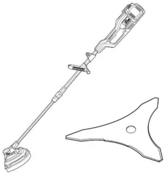
BRUSH CUTTER
Cutting Circle: ∅255mm
Max. Blade Speed: 6,400/min
POLE PRUNER
Bar Length: 200mm (8")
Cutting Length: 180mm
Max. Cutting Speed: 10m/s
Oil Tank Cap.: 100ml
Bar & Chain: Oregon®
Chain Pitch: 9.53mm (3/8")
Chain Gauge: 1.10mm (0.043")
POLE HEDGE TRIMMER
Cuts/min: 2400
Cutting Length: 450mm
Blade Length: 510mm
Max. Cutting Cap.: ∅16mm
EXTENSION POLE
Length: 670mm
natural_image
Technical line drawing of a handheld device with a separate triangular component (no text or symbols)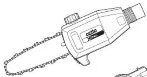
natural_image
Line drawing of a chain-linking device with no text or symbols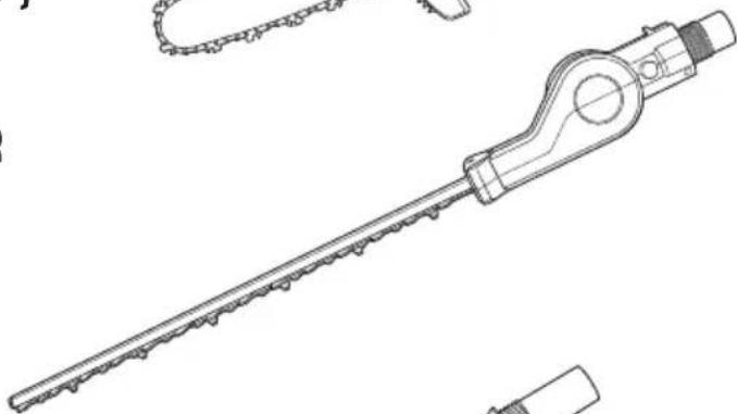
natural_image
Technical line drawing of a mechanical tool with a long rod and flanged end (no text or symbols)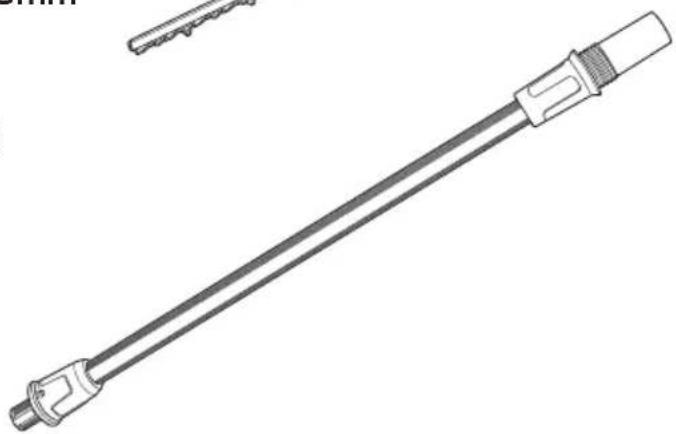
natural_image
Technical line drawing of a mechanical tool or connector with a cylindrical shaft and flange (no text or symbols)KNOW YOUR PRODUCT
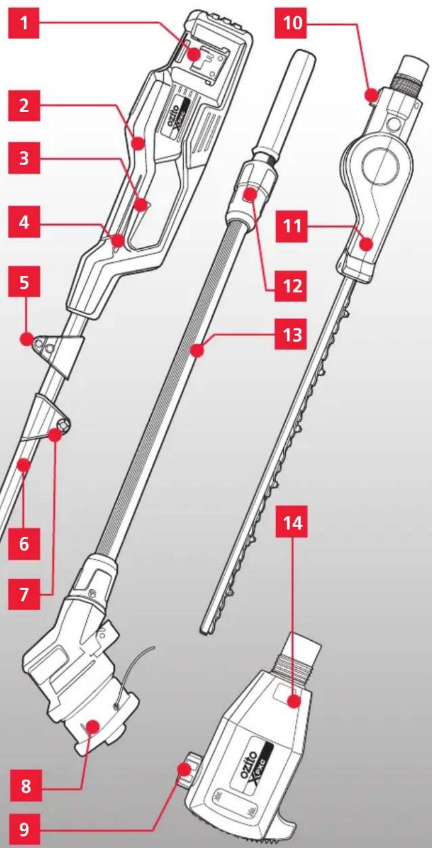
BRUSHLESS 4-IN-1 MULTI TOOL KIT
- Battery Seating x 2
- Rear Handle
- On/Off Trigger
- Safety Switch
- Shoulder Strap Holder
- Motor Tube
- Handle Bracket
- Line Spool
- Chain & Bar Oil Tank
- Lock Release
- Hedge Trimmer Attachment
- Tube Nut
- Connecting Tube
- Pruner Attachment
- Extension Pole
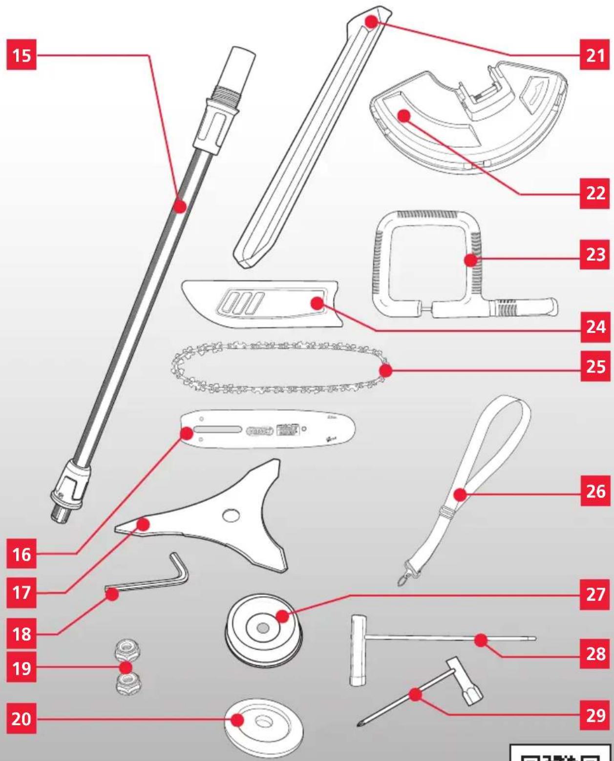
- Guide Bar
- Brush Cutter Blade
- Hex Key M5
- Blade Nut x 2
- Pressure Plate
- Blade Cover
- Safety Guard
- Front Handle
- Bar & Chain Cover
- Chain
- Shoulder Strap
- Pressure Plate Cover
28.Multi-tool 13/4mm - Multi-tool 19mm
ONLINE MANUAL
Scan this QR Code with your mobile device to take you to the online manual.

CONTENTS
POWER TOOL SAFETY WARNINGS...... Page 2
SPECIFICATIONS...... Page 7
KNOW YOUR PRODUCT...... Page 8
STEPUP & PREPARATION...... Page 11
Assembly.... 11
Line Spool....
Brush Cutter Blade.... 13
Chain & Bar.... 14
Attachment.... 17
Shoulder Strap....
OPERATION...... Page 20
APPLICATIONS......Page 22
Line Trimmer/Brush Cutter.... 22
Pole Pruner....
Pole Hedge Trimmer.... 28
MAINTENANCE......Page 30
Line Replacement.... 30
Maintaining the Guide Bar.... 32
Hedge Trimmer Blade.... 33
Cleaning, Storage and Transport...... 34
TROUBLESHOOTING...... Page 35
SPARE PARTS...... Page 36
DESCRIPTION OF SYMBOLS...... Page 37
WARRANTY...... Page 40
SETUP & PREPARATION
1. ASSEMBLY

WARNING! ENSURE THE TOOL IS OFF AND THE BATTERIES REMOVED BEFORE PERFORMING ANY OF THE FOLLOWING OPERATIONS.
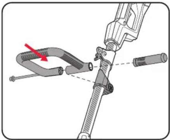
Fitting the Front Handle
-
Using the provided 5mm hex key, unscrew the socket head screw from the front handle and side grip.
-
Place the front handle on the handle bracket located on the shaft.
-
Insert the socket head screw through the front handle and the handle bracket. Screw the side grip onto the protruding end of the socket head screw to tighten.
natural_image
Mechanical assembly diagram showing a tool interacting with a clamped component (no text or symbols present)Note: If necessary you can adjust the position of the front handle by loosening the side grip, tighten the side grip to lock in place.
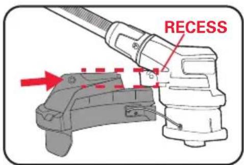
Fitting the Safety Guard
-
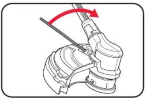
Using the provided 5mm hex key, unscrew the socket head screw from the safety guard.
-
Push the safety guard onto the recess on the rear of the gear housing as far as it will go and screw it securely in place with the previously removed socket head screw.
Note: The knife edge blade on the underside of the safety guard automatically cuts the line to the optimum length.
- Remove the sticker from the knife edge blade before using the line spool.
natural_image
Mechanical assembly diagram showing a lever mechanism with a red arrow indicating rotation (no text or symbols present)
WARNING! TAKE CARE NOT TO CUT YOURSELF ON THE KNIFE EDGE BLADE.
SETUP & PREPARATION [cont.]
2. LINE SPOOL

WARNING! ENSURE THE TOOL IS OFF AND THE BATTERIES REMOVED BEFORE PERFORMING ANY OF THE FOLLOWING OPERATIONS.
Removing and Fitting the Line Spool
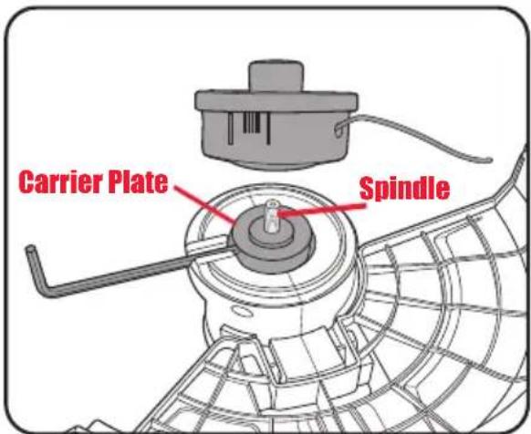
- To remove, turn the line spool until you can see the hole in the carrier plate at the housing recess and insert the supplied 5mm hex key. While holding the hex key, turn the line spool clockwise (left-hand thread) to remove.
- To fit the line spool the carrier plate must be fitted over the spindle as this provides the ability to lock the spindle from turning when fitting or removing the line spool.
- Align the hole in the carrier plate with the housing recess and insert the supplied 5mm hex key. While
holding the hex key, screw the line spool onto the spindle thread, turning counterclockwise (left-hand thread) until tight. Remove the hex key.

WARNING! DO NOT OPERATE THE LINE TRIMMER ATTACHMENT WITHOUT THE SAFETY GUARD FITTED.
3. BRUSH CUTTER BLADE

WARNING! ENSURE THE TOOL IS OFF AND THE BATTERIES REMOVED BEFORE PERFORMING ANY OF THE FOLLOWING OPERATIONS.

WARNING! THE BRUSH CUTTER BLADE HAS SHARP EDGES. FOR YOUR SAFETY, PLEASE USE GLOVES.
Fitting and Removing the Brush Cutter Blade
Note: To fit the brush cutter blade, the line spool must be removed. See Removing and Fitting the Line Spool.
Note: Keep the blade cover on while fitting and removing the brush cutter blade.
-
To fit the brush cutter blade the carrier plate must be fitted over the spindle as this provides the ability to lock the spindle from turning when fitting or removing the brush cutter blade.
-
Place the brush cutter blade onto the carrier plate, ensuring that the hole in the blade is correctly seated.
-
Place the pressure plate on the spindle, followed by the pressure plate cover and loosely fit the blade nut, turning counter-clockwise (left-hand thread).
-
Before tightening the blade nut, align the hole in the carrier plate with the housing recess and insert the 5mm hex key. While holding the hex key in
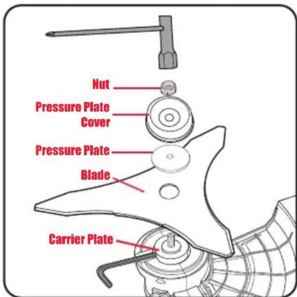
place, Tighten the blade nut with the multi-tool 19mm, turning anti-clockwise. Remove the hex key.
- To remove the brush cutter blade rotate the blade nut clockwise to remove.

WARNING! DO NOT OPERATE THE BRUSH CUTTER ATTACHMENT WITHOUT THE SAFETY GUARD FITTED.

WARNING! THE BLADE NUT (M10 SELF-LOCKING, LEFT-HAND THREAD) MUST NOT BE RE-USED. WHEN RE-INSTALLING THE BLADE, USE A NEW BLADE NUT. FAILURE TO FOLLOW THIS PROCEDURE CAN RESULT IN SERIOUS INJURY.
Note: Spare blade nut (M10 x 1.25) can be ordered from Special Orders Desk at your local Bunnings Warehouse.
SETUP & PREPARATION [cont.]
4. CHAIN & BAR

WARNING! ENSURE THE TOOL IS OFF AND THE BATTERIES REMOVED BEFORE PERFORMING ANY OF THE FOLLOWING OPERATIONS.

WARNING! ALWAYS WEAR GLOVES WHEN HANDLING THE CHAIN AS IT IS VERY SHARP AND CAN CUT YOU WHEN IT IS NOT MOVING.
Fitting the Guide Bar & Chain
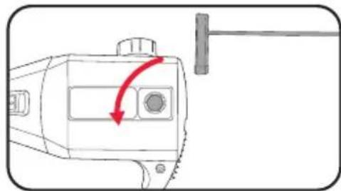
- Using supplied multi-tool 13/4mm remove the chain
sprocket cover bolt then remove chain sprocket cover.
natural_image
Technical line drawing of a mechanical device with a red arrow indicating rotation or movement (no text or symbols)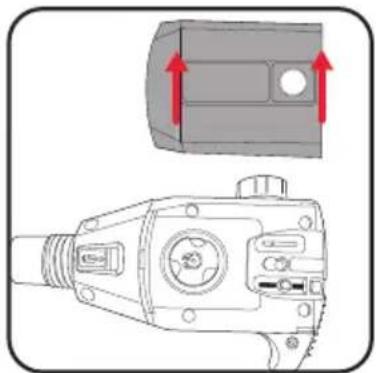
natural_image
Technical illustration of a mechanical device with a top view showing a component and a side-view view of its internal structure (no text or symbols present)- Place the chain in the groove of the guide bar as shown. Refer to the label on guide bar and chain sprocket cover that indicates the direction that the chain should face.
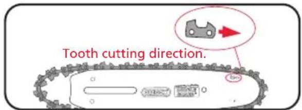

WARNING! IF THE CHAIN IS INSTALLED BACKWARDS (CHAIN CUTTERS ARE FACING IN THE OPPOSITE DIRECTION OF ROTATION) THE POLE PRUNER WILL VIBRATE EXCESSIVELY AND NOT CUT.
- Place the guide bar and chain onto the mount, ensuring that the chain tensioning pin (a) sits within the lower hole on the guide bar.
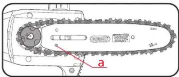
- Adjust the chain tensioning screw (b) with the multi-tool until the chain tension pin (a) fits into the hole in the guide bar, whilst guiding the chain around the sprocket.
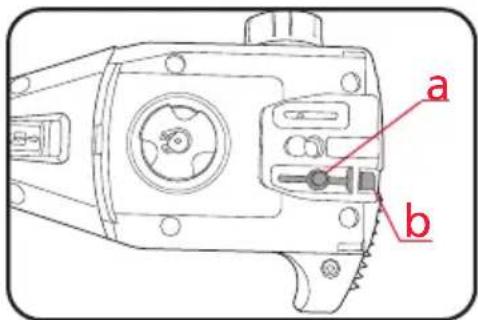
- Re-mount and finger-tighten the chain sprocket cover with the chain sprocket cover bolt.
Note: Only tighten the chain sprocket cover bolt securely once the chain tension has been adjusted (see: Tensioning the chain.)
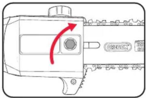
Tensioning the Chain
- Using supplied multi-tool 13/4mm loosen the chain sprocket cover bolt. Do not remove chain sprocket cover.

WARNING! IF YOU TRY TO ROTATE THE CHAIN TENSIONING SCREW (b) WHILST THE CHAIN SPROCKET COVER BOLT IS T, IT WILL RESULT IN THE CHAIN NOT OPENING AND POSSIBLE DAMAGE TO THE IN TENSIONING SCREW AND THE CHAIN SIONING PIN.
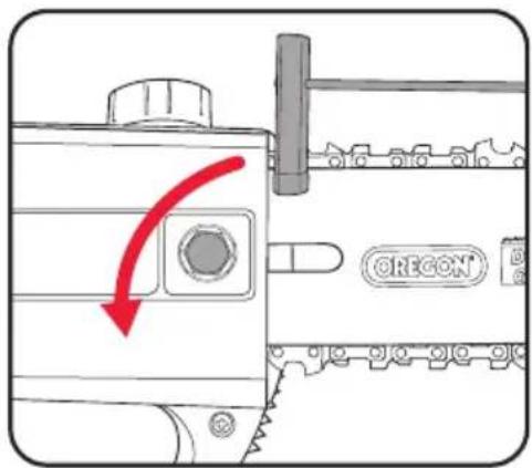
- Adjust the chain tension with the multi-tool 13/4mm. Turning CLOCKWISE increases the chain
tension, turning it COUNTER-CLOCKWISE decreases the chain tension.
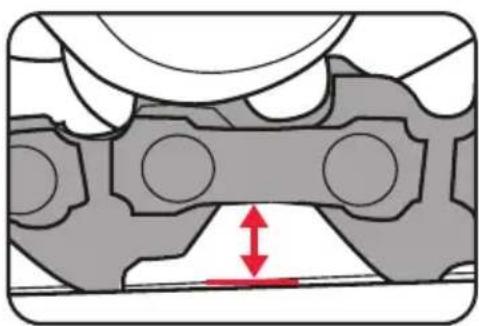
For the correct chain tension, firmly pull up on the chain at the middle of the top of the exposed guide bar. When the chain is pulled up to its highest point, the bottom tip of the links should only just stay in the track [middle of the guide bar].
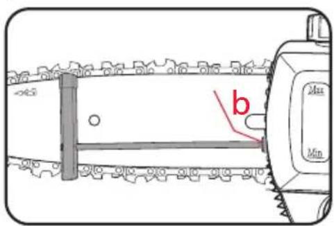
- Once the correct tension has been achieved, tighten the chain sprocket cover bolt to lock the chain bar in place.
Note: Chains lengthen slightly as the link pins set into place. They set into place from the load applied to the chain, this process continues throughout the life of all chains as they gradually wear from use.
natural_image
Mechanical assembly diagram showing a bearing housing with red directional arrows indicating motion or force (no text or symbols)SETUP & PREPARATION [cont.]
![Ozito PXGMTK-4182 - SETUP & PREPARATION [cont.] - 1](/content/2026/05/1055986/images/7d2962da5d01a5b49fe9f26178224dc89e09054a83781df9aebf0759f229b7af.jpg)
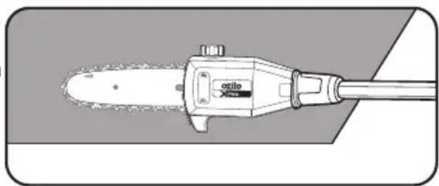
WARNING! NEVER OPERATE UNLESS THE CHAIN AND BAR ARE LUBRICATED.
![Ozito PXGMTK-4182 - SETUP & PREPARATION [cont.] - 2](/content/2026/05/1055986/images/da859aff91ca674c9195906f1f1d057a14587c91b6b0eae2a544951d9494bbea.jpg)
WARNING! ONLY USE OIL THAT IS EXPRESSLY LABELLED "CHAIN BAR OIL".
Chain Lubrication
-
Place the pole pruner on a level surface.
-
Clean the area around the oil tank cap and then open it.
-
Fill the chain bar oil tank with CHAIN BAR OIL (not supplied). In doing so, make sure that no dirt gets into the oil tank. This will ensure that the oil nozzle does not clog. Tank capacity 100ml. Do not overfill.
-
Refit the oil tank cap.
-
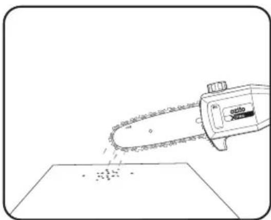
To check the lubricating system, when running hold it with the guide bar and chain above some light coloured paper such as newspaper. A steadily increasing stain caused by oil spray shows the lubricating system is working.
Note: Guide bar oil may leak if the tool is left for long periods. This is normal. If the tool is to be left unused for an extended time, drain the oil from the tank. Refill before use.
natural_image
Technical line drawing of a mechanical tool labeled 'accel' with no visible text or symbols beyond the label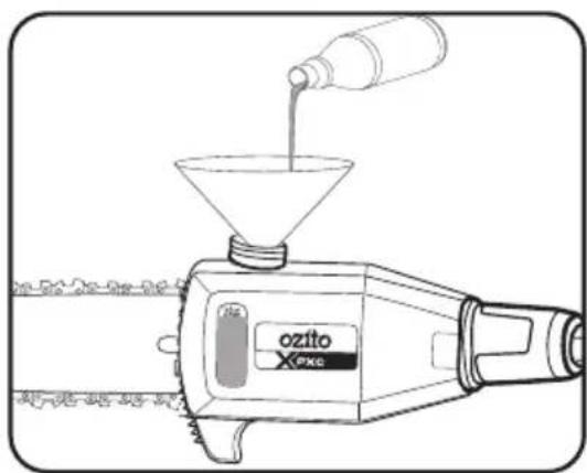
natural_image
Line drawing of a chainsaw cutting down a flat surface with scattered debris (no text or symbols)5. ATTACHMENT

WARNING! ENSURE THE TOOL IS OFF AND THE BATTERIES REMOVED BEFORE PERFORMING ANY OF THE FOLLOWING OPERATIONS.
Fitting and Removing Attachments
To be able to use a different attachment they must be fitted to the connecting tube.
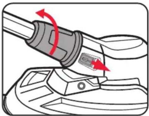
To Remove Fitted Attachment:
- Push the lock release forward (unlock position) and turn the tube nut anti-clockwise to fully loosen.
Note: The locking and unlocking directions are indicated on the tube nut.
- Pull the connecting tube away from the attachment.
natural_image
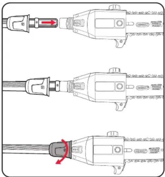
Diagram of a mechanical component with red arrows indicating rotation or movement (no text or symbols)To Fit Selected Attachment:
- Push the connecting tube carefully into the selected attachment.
Note: Each attachment can only be fitted one way. Do not force connecting tube into the attachment, turn the attachment over if it does not fit first time.
- To lock the attachment in place, turn the tube nut clockwise until tight.
SETUP & PREPARATION [cont.]
Fitting the Connecting Tube on the Motor Tube
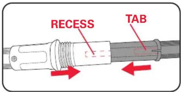
Depending on the attachment fitted, the connecting tube can be connected directly to the motor tube if the extension pole is not needed.
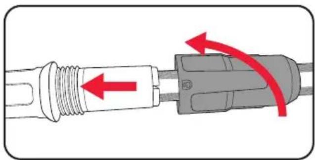
- Push the connecting tube carefully into the motor tube, aligning the tab with the recess as you do so. Push both halves together until it will not go any further.
Note: The connecting tube can only be fitted one way. Do not force connecting tube into the motor tube, turn the attachment over if it does not fit first time.
- To lock together, turn the tube nut clockwise until tight.
natural_image
Diagram of a plug with red directional arrows indicating internal components (no text or symbols)Fitting the Extension Pole
Depending on the required working height, the extension pole can be fitted between the connecting tube and motor tube.
Note: The connecting tube will need to be removed from the motor tube if fitted.
- The extension pole fits into the motor tube the same way as the connecting tube as described above.
Note: The extension pole can only be fitted one way. Do not force the extension pole into the motor tube, turn the attachment over if it does not fit first time.
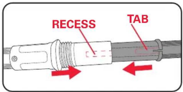
- To lock together, turn the tube nut clockwise until tight.
6. SHOULDER STRAP
Attaching the Shoulder Strap
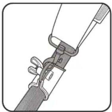
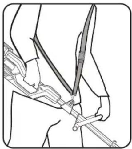
- Fasten to the shoulder strap holder on the motor tube.
natural_image
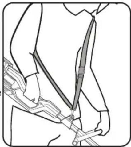
Technical line drawing of a mechanical clamp or bracket assembly (no text or symbols)- Wear the shoulder strap over your shoulder.
- In order to establish the optimum length of the shoulder strap, you should then make a few swinging movements without starting the motor. Using the strap adjuster on the shoulder strap, make adjustments until you achieve the most comfortable working and cutting position.
- The shoulder strap is fitted with a quick-release buckle, press the hooks together if you need to put down the tool quickly.
Note: If necessary you can adjust the position of the shoulder strap holder on the motor tube. To do so, loosen the wing nut and move the shoulder strap holder as required and then retighten the wing nut.
natural_image
Line drawing of a person wearing a long-sleeve shirt and holding a long object, with no visible text or symbols.
WARNING! ALWAYS USE THE SHOULDER STRAP WHEN WORKING WITH THE UNIT. ATTACH THE STRAP BEFORE SWITCHING ON. SWITCH OFF THE MOTOR BEFORE YOU TAKE OFF THE SHOULDER STRAP.
OPERATION
7. BATTERIES
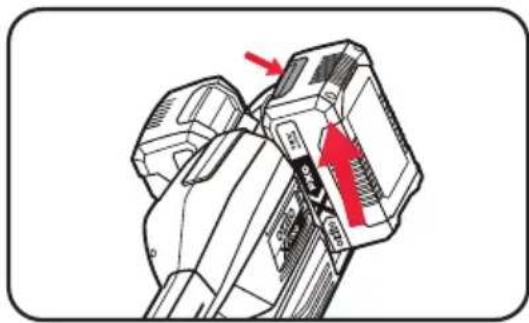
Installing and Removing the Batteries
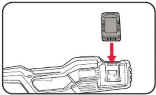
Only use 2 batteries with the same capacity. Always use 2 batteries with the same charge state with the tool.
- Slide two batteries of the same capacity and same charge state into the tool aligning the ribs so that they click into place.
natural_image
Diagram showing a device component with a red arrow pointing to a highlighted section (no text or symbols present)- To remove, press and hold the battery release tab and then slide out.
natural_image
Technical illustration of a mechanical component with red arrows indicating direction (no text or symbols)8. SWITCHING ON/OFF
Switching On
- Hold the tool firmly with one hand on the rear handle and the other hand on the front handle.
natural_image
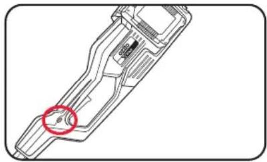
Line drawing of a person holding a sword and a knife, no text or symbols present- Press and hold the safety switch with your thumb.
natural_image
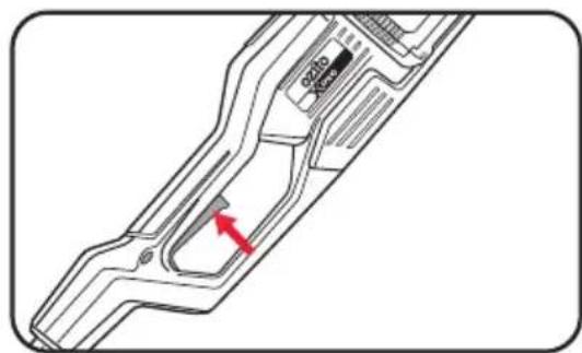
Technical line drawing of a mechanical component with a red circle highlighting a specific feature (no text or symbols present)- Squeeze the on/off trigger to start the motor.
natural_image
Technical diagram of a mechanical component with a red arrow indicating a specific feature (no text or symbols present)Switching Off
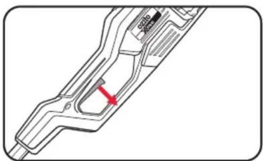
- Release the on/off trigger and allow the motor to come to a complete standstill.
natural_image
Technical line drawing of a mechanical component with a red arrow indicating a specific part (no text or symbols present)APPLICATIONS
9. LINE TRIMMER/BRUSH CUTTER
Extending the Cutting Line
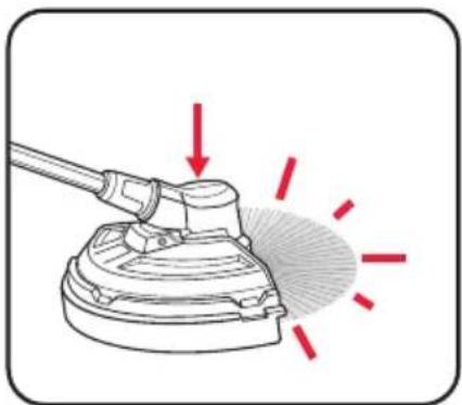
The line trimmer is fitted with a bump feed function which allows the line to be feed without stopping the line trimmer. If the line trimmer is not cutting correctly the line may need to be feed using this feature.
-
While the line trimmer is still on, simply bump the head of the trimmer on the ground to allow the line to feed out.
-
The bump feed will automatically lock once off the ground so that the line will stop feeding.
natural_image
Diagram of a cleaning tool emitting red light rays, no text or symbols present
WARNING! DO NOT BUMP THE HEAD ON ANY HARD SURFACES SUCH AS CONCRETE OR BRICK, THIS COULD CAUSE DAMAGE TO THE LINE TRIMMER.

WARNING! DO NOT USE ANY KIND OF METAL WIRE OR METAL WIRE ENCASED IN PLASTIC IN THE LINE SPOOL. THIS MAY CAUSE SERIOUS INJURIES TO THE USER.
Trimming/Mowing
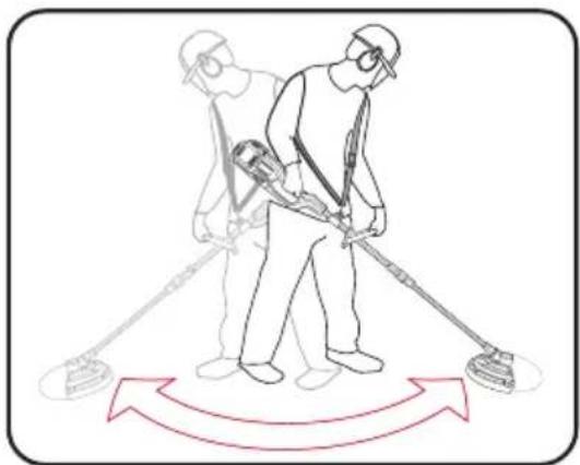
Swing the trimmer from side to side as you walk forward. Always keep the line spool parallel to the ground. Check the site and decide what cutting height you require. Guide and hold the trimmer at the required height to ensure that you cut evenly.
natural_image
Illustration of two workers using a handheld tool with directional arrows indicating movement (no text or symbols)Low Trimming & Mowing
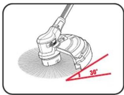
For mowing, you want to cut all the vegetation down to the ground. To do this, set the trimmer at an angle of 30^ to the right. Place the handle in the required position.
Remember the increased risk of injury to the user, watchers and animals and the danger of damaging other items due to objects (for example stones) being thrown out. Always cut away from yourself. Never draw the trimmer towards yourself.

WARNING! TAKE EXTREME CARE DURING MOWING WORK. WHEN DOING SUCH WORK KEEP A DISTANCE OF 30 METERS BETWEEN SELF AND OTHER PEOPLE OR ANIMALS.
Cutting along Fences/Foundations/Trees
When cutting approach wire mesh fences, natural stone walls and foundations slowly so that you can cut close to them without striking the obstacle with the line. If, for example, the line strikes stones, stone walls or foundations, it will wear or fray.
If the line strikes wire fencing it will break. When trimming around tree trunks, approach slowly so that the line does not strike the bark. Approach grass or weeds with the tip of the line and tilt the line spool forwards slightly.
Jamming
If the cutting blade jams as a result of attempting to cut vegetation that is too dense, switch off the engine immediately. Remove the grass and scrub from the trimmer before you restart it.
Preventing Recoil
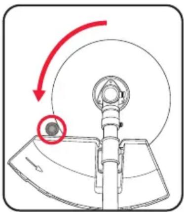
When you work with the blade there is a risk of recoil if it strikes solid objects such as tree trunks, branches, tree stumps, stones or the like. This will throw the trimmer backwards in the direction opposite to the rotation of the tool. This can cause you to lose control of the trimmer. Do not use the blade near fences, metal posts, boundary stones or foundations. For cutting dense stalks, position it as shown to prevent recoil.
natural_image
Mechanical diagram showing a rotating component with a red arrow indicating motion direction (no text or symbols)
WARNING! DO NOT REMOVE ANY OBJECTS FROM FOOTPATHS, ETC.
USING THE TRIMMER. THE TRIMMER IS A POWERFUL TOOL AND CAN
THROW SMALL STONES AND OTHER OBJECTS A DISTANCE OF 15
METERS OR MORE, CAUSING INJURIES AND DAMAGE TO CARS, HOUSES AND WINDOWS.
APPLICATIONS [cont.]
10. POLE PRUNER
Chain Lubrication
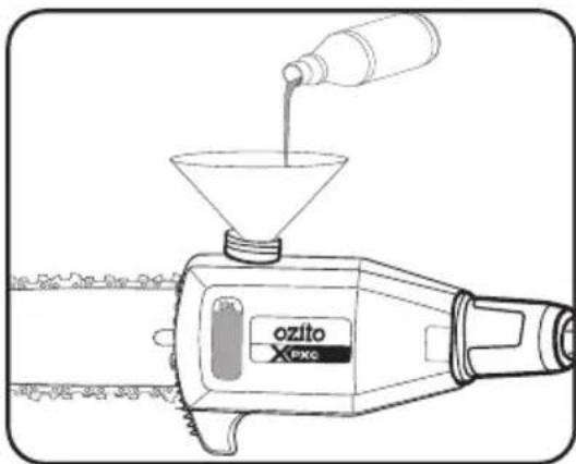
Level of oil in the oil container: Both before and during your work make sure that there is always sufficient oil in the system. To avoid damaging the bar & chain, never run the pruner if there is no oil in the system or if the oil drops below the "min" mark. On average, a single filling will last around 10 minutes depending on the number of pauses in cutting and the loads involved.
natural_image
Line drawing of a ozito spray gun with funnel and bottle pouring liquid (no text or symbols)Chain Tension
Tension of the chain, condition of the cutting elements: The sharper the chain, the easier and more controllable it is to operate the pruner. The same also applies to the chain tension. For greater safety you must check the chain tension before your work and at least every 10 minutes during your work. New chains in particular tend to expand more (see Tensioning the Chain.)
Safe Working
Never stand under the branch you want to saw. Use special caution when working with branches under tension and splintering wood.
Possible risk of injury caused by falling branches and catapulting pieces of wood.
When the equipment is in operation, keep other persons and animals away from the danger zone. The equipment is not protected from electric shock through contact with high-voltage cables. Keep a minimum distance of 10m from live cables. Electric shock can cause fatal injury. When working on slopes always stand to the upper or left or right side of the branch you want to cut.
Hold the equipment as close as possible to your body. This will help you to keep your balance.
Always hold the equipment firmly with both hands.
Protective Clothing
Make absolutely sure to wear the appropriate, close fitting protective clothing, such as protective pants, gloves and safety shoes. Wear hearing protection and protective goggles a safety helmet with a face guard will provide protection against falling and recoiling branches.

WARNING! THE CHAIN COMES IN CONTACT WITH A HARD OBJECT, VISUALLY INSPECT THE CHAIN & BAR FOR DAMAGE. IF THE CHAIN OR BAR IS DAMAGED, DO NOT CONTINUE TO OPERATE THE POLE PRUNER.

WARNING! NEVER USE THE POLE PRUNER WHEN STANDING ON A LADDER OR UNEVEN GROUND. DO NOT OVERREACH. ALWAYS USE BOTH HANDS TO HOLD THE POLE PRUNER.

WARNING! ENSURE APPROPRIATE CARE IS TAKEN WHEN CUTTING ABOVE SHOULDER HEIGHT.
Pruning
Pruning is the removal of a limb or branch from a standing tree.

Limbing
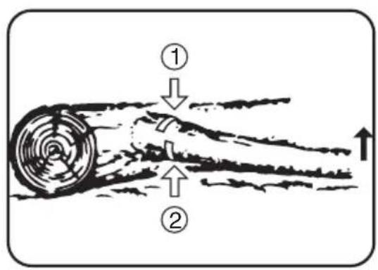
Limbing is the process of removing the branches from a fallen tree. Check the direction in which a branch will bend before cutting it. Always cut on the opposite side to the bending direction so that the guide bar is not pinched in the cut. For large limbs that cannot be removed in one cut, make an initial cut from the bent side and finish by sawing from the opposite direction. Do not remove limbs that are supporting the fallen tree on the ground until the tree has been cut into lengths.
APPLICATIONS [cont.]
Sawing Techniques
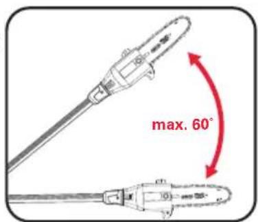
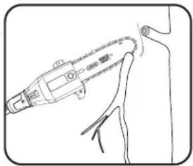
- When removing branches, hold the pruner at an angle ranging from a maximum 60^ to horizontal in order to avoid being struck by a falling branch.
- At the end of the cut, the weight of the pruner suddenly increases for the user, because it is no longer supported on the branch. There is the risk of losing control of the pruner.
- Saw off the lower branches on the tree first. By doing so, it is easier for the cut branches to fall to the ground.
- Only pull the pruner out of the cut with the chain running. By doing so, you can prevent it from getting jammed.
- Do not saw with the tip of the guide bar. This could lead to kick back and possible injury.
natural_image
Line drawing of a medical or laboratory procedure showing a hand holding a device near a human head (no text or symbols present)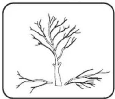
natural_image
Simple line drawing of a tree with two branches and roots, enclosed in a rounded square frame (no text or symbols)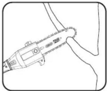
natural_image
Line drawing of a medical or surgical instrument interacting with a curved tool (no text or symbols visible)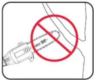
Cutting Wood Under Tension
Special care is required when cutting wood which is under tension. cutting wood which is under tension can release the tension, causing the wood to react out of control. In the worst case this can result in sever and even fatal injuries.
This type of work must be performed only by specially trained persons.
Kickback
The term “kickback” describes what happens when the running pruner suddenly kicks upward and backward. Usually this is caused by contact between the tip of the cutter bar and the workpiece or by the chain becoming trapped. In the event of kickback, large forces occur suddenly and violently. As a result, the pruner usually reacts uncontrollably. This can often result in very serious injuries to the worker or persons in the vicinity. The risk of kickback is at its greatest when the pruner is positioned for a cut in the region of the tip of the cutter bar, as the leverage effect is greatest there. It is therefore safest to position the pruner as flat as possible.
11. POLE HEDGE TRIMMER
Adjusting the Angle

WARNING! ENSURE THE TOOL IS OFF AND THE BATTERIES REMOVED BEFORE PERFORMING ANY OF THE FOLLOWING OPERATIONS.
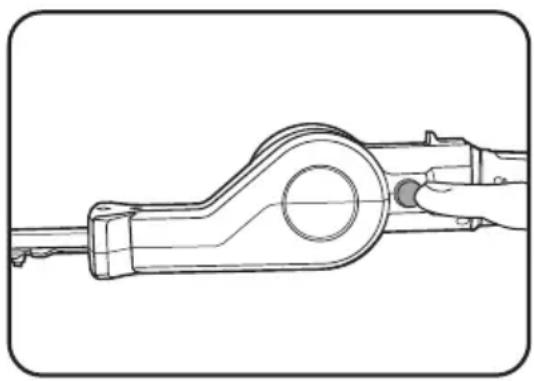
The cutting blade can be tilted in order to ensure an ergonomic working position. Press the lock-off button and adjust the tilt of the housing to any of 7 latching positions.
natural_image
Technical line drawing of a mechanical component with a hand holding a knob (no text or symbols)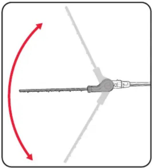
natural_image
Diagram of a mechanical tool with red and gray directional arrows indicating rotation or movement (no text or symbols)
WARNING! NEVER USE THE POLE HEDGE TRIMMER WHEN STANDING ON A LADDER OR UNEVEN GROUND. DO NOT OVERREACH. ALWAYS USE BOTH HANDS TO HOLD THE POLE HEDGE TRIMMER.

WARNING! FAMILIARISE YOURSELF WITH SURROUNDING HAZARDS SUCH AS POWER LINES, PHONE LINES, METAL FENCES AND OTHER OBJECTS THAT COULD BE IN YOUR TRIMMING PATH, FAILURE TO DO SO COULD RESULT IN ELECTRICAL SHOCK, PERSONAL INJURY OR DAMAGE TO YOUR POLE HEDGE TRIMMER.

WARNING! IF THE BLADES COME IN CONTACT WITH A HARD OBJECT, VISUALLY INSPECT THE BLADE FOR DAMAGE. IF THE BLADE IS DAMAGED, DO NOT CONTINUE TO OPERATE THE POLE HEDGE TRIMMER.
Cutting New Growth
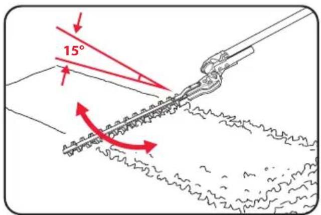
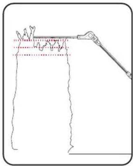
The most effective method is to use wide, sweeping movements, guiding the cutting edge of the blade straight through the branches. A slight incline of the blade downwards in the direction of movement will produce the best cutting results. It is recommended to tie a guide line of string or the like along the hedge so that you cut the hedge to a level height. The branches above it will be cut off.
Note: Do not use the pole hedge trimmer for cutting stems greater than ∅16mm. Use the trimmer only for cutting normal shrubbery found around houses and buildings.
Cutting the Sides of a Hedge
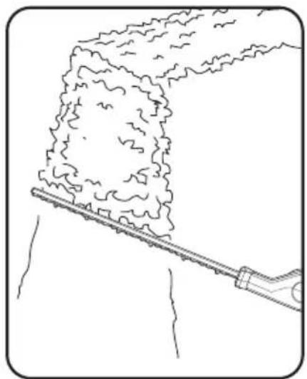
Cut the sides of a hedge with curve-shaped movements from the bottom up. For design reasons, the engine might stall when the tank is not full and you use the equipment to cut the sides of long hedges.
natural_image
Line drawing of a pipe cutting through a narrow trench with a mesh texture (no text or symbols)Cutting the Top
Where the branches have grown extremely long, cut back the hedge in several stages.
natural_image
Diagram of a mechanical clamp or tool interacting with a vertical surface, showing no text or symbols.MAINTENANCE

WARNING! BEFORE CLEANING OR CARRY OUT ANY MAINTENANCE PROCEDURE ENSURE THE TOOL IS OFF AND THE BATTERIES ARE REMOVED.
Replacing the Spool/Clearing Jams and Tangled Line
From time to time, especially when cutting thick or stocky weeds, the line feeding hub may become clogged with sap or other material and the line will become jammed as a result. To clear the jam, follow these steps.
- Turn off the line trimmer and remove the batteries.
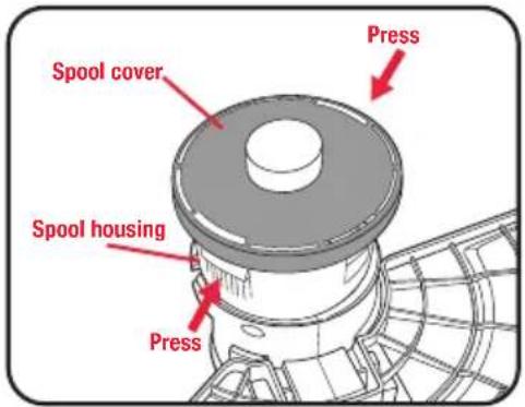
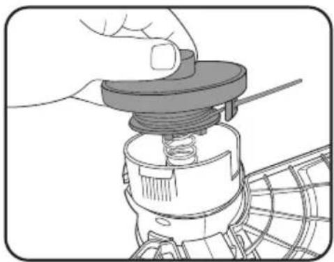
- Press the release tabs on the side of the spool housing and remove the spool cover and spool by pulling it straight off.
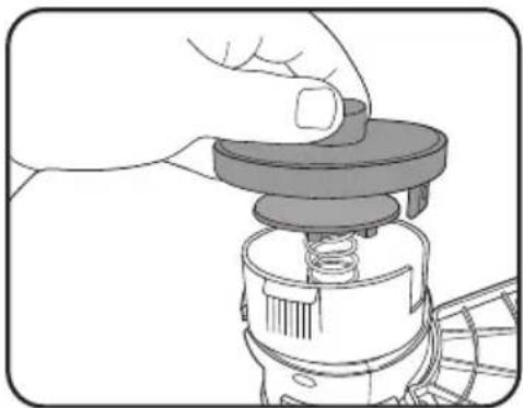
- Lift the spool of nylon line out of the housing and clear any broken line or cutting debris from the spool area.
natural_image
Illustration of a hand adjusting a mechanical component with a spring (no text or symbols)-
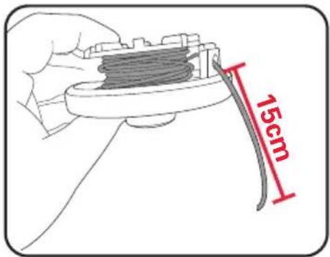
In case of jams and tangled line, unwrap about 15cm of line to ensure that it is undamaged. If it is OK, thread the end of the line spool through the eyelet in the spool cover
-
Snap the spool cover back onto the spool housing.
-
Turn the line trimmer back to its normal orientation, insert the battery and turn the tool on. If the length of the line is excessive, you'll hear it being cut automatically to the proper length.
natural_image
Illustration of a hand adjusting a mechanical component with a spring and threaded shaft (no text or symbols)Rewinding Spool from Bulk Line
Bulk line for your line trimmer is available from your local dealer. To install, follow steps:
-
Remove the spool as described in steps 1 - 3 of the "Replacing the spool/clearing jams and tangled lines" section.
-
Cut a length of ∅2.0mm line, approximately 8m long.
-
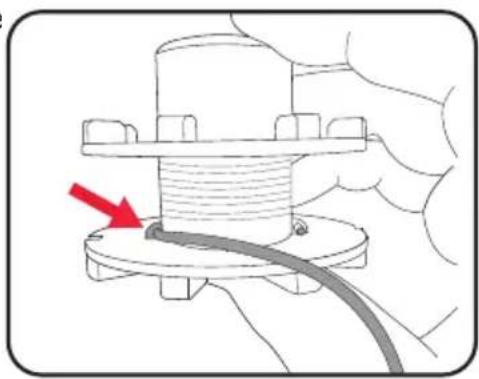
Insert the new cutting line through the line mount inside the spool.
-
Wind the line evenly with tension in a counterclockwise direction.
-
To ensure that the line does not unravel while the spool is being loaded, the line can be clipped into one of the notches on the outer of the spool.
natural_image
Diagram of a mechanical assembly with a red arrow indicating a specific component (no text or symbols present)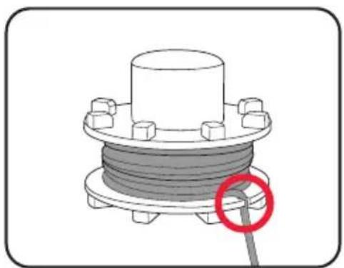
natural_image
Mechanical component with coiled spring and bolted base, highlighted by a red circle (no text or symbols)-
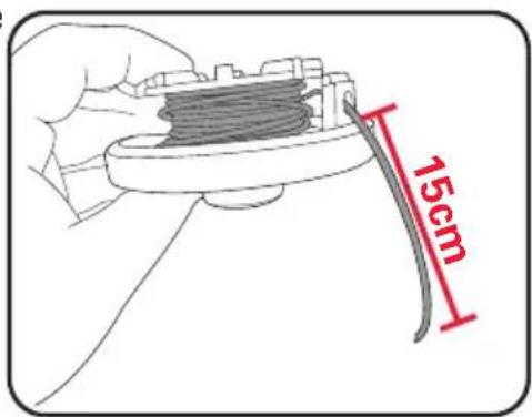
Thread the end of the line on the new line spool through the eyelet in the spool cover.
-
Pull the line sharply to release it from notch.
-
Re-seat the spool as described in steps 5 - 6 of the "Replacing the spool/clearing jams and tangled lines" section.
MAINTENANCE [cont.]
Maintaining the Guide Bar

WARNING! ALWAYS WEAR GLOVE WHEN HANDLING THE CHAIN AS IT IS VERY SHARP AND CAN CUT YOU WHEN IT IS NOT MOVING.
-
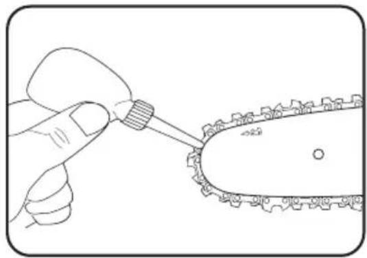
Remove any sawdust from the guide bar, including the groove. Oil and sawdust combine and emit a burning smell during operation if the guide bar is not regularly cleaned.
-
Make sure that the oil port is not clogged. Grease the nose sprocket at the tip of the guide bar.
-
Check for oil leakage and loose fastenings, especially those securing the handles and the guide bar.
-
Reverse the guide bar every 8 working hours to ensure uniform wear. Check the guide rails frequently and if necessary remove burrs and square up the rails using a flat file.
natural_image
Illustration of a hand using a tool to apply a mechanical component to a chain (no text or symbols present)Chain Sharpening
Chain File: 4.0mm (5/32")
Chain Pitch: 9.52mm (3/8" LP)
Chain Gauge: 1.10mm (0.043")
Sharpen the chain regularly to maintain optimum performance of the saw. Signs of a dull chain are:
• The sawdust becomes powder-like
- Extra force is required to execute a cut
• The cut does not track in a straight line
- Increased vibration
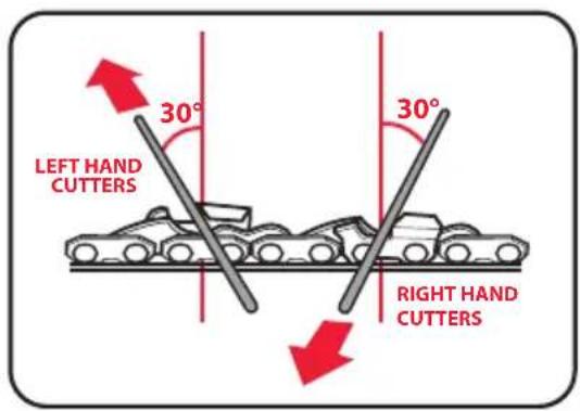
Sharpen each cutter using a round 4.0mm (5/32") chain
file. Keep the file level with the top plate of the tooth. Always use outward strokes and maintain a 30^ angle between the chain and file. After sharpening, the cutters must all have the same width and length.
After every 3–4 uses get an authorised repair centre to professionally sharpen your chain. They have the special tools necessary to ensure the correct cutting angles and depths.
Automatic Chain Lubrication
You should check the operation of the automatic chain lubrication system on a regular basis in order to guard against overheating and the damage this can cause to the guide bar and the chain.
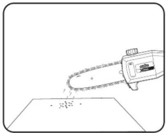
Point the tip of the guide bar above some light coloured paper such as newspaper and allow the pruner to run. If you see a growing oil stain on the paper surface, the automatic chain lubrication system is working properly. If no clear oil trace is evident then please refer to the corresponding instructions in "Troubleshooting". If the information contained there still fails to remedy the situation, please contact our service department or another similarly qualified workshop. Do not actually touch the surface with the tip of the cutter rail when performing this test. Keep a safe distance (approx. 20 cm).
natural_image
Line drawing of a chain-linking tool cutting down a flat surface (no text or symbols)Pole Hedge Trimmer Blade
The high-quality cutter blades are made of tempered steel, and in normal use there is no need to sharpen the blades. If you accidentally strike a wire, stone, glass or other hard object, this may produce a notch in the blade.
There is no need to remove the notch as long as it does not adversely affect the movement of the cutting edges. If it does adversely affect this movement, switch off the machine and use a fine file or a fine grinding stone to remove the notch.
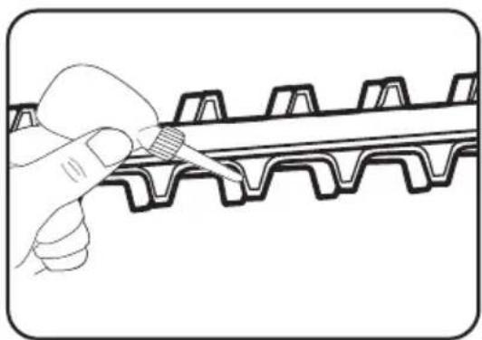
Make sure that the cutting blade is always well oiled. Lay the pole hedge trimmer on a flat surface. Apply a light weight machine oil along the edge of the top blade.
natural_image
Illustration of a hand using a tool to trim a gear tooth (no text or symbols)MAINTENANCE [cont.]
Cleaning, Storage and Transport

WARNING! BEFORE CLEANING OR CARRY OUT ANY MAINTENANCE PROCEDURE ENSURE THE TOOL IS OFF AND THE BATTERIES ARE REMOVED.
Cleaning
- Keep ventilation slots of the tool clean at all times. Periodically clean out the grass from the cutting head and the rim of the safety guard to ensure efficient operation at all times.
- After each use, blow air through the tool housing to ensure it is free from all dust, dirt, etc. Build up of dust, dirt particles may cause the tool to overheat and shorten the life of the tool.
- If the housing of the trimmer requires cleaning, do not use solvents but a moist soft cloth or soft brush only.
- Never let any liquid get inside the tool, never immerse any part of the tool into liquid.
- Keep the handles free of oil so that you can maintain a firm grip.
- No lubrication is necessary as the tool has sealed bearings.
- If you are not going to use the pruner for an extended period of time, remove the chain oil from the tank. Briefly immerse the saw chain and the guide bar into an oil bath and then wrap them in oil paper.
- When not in use, the line trimmer should be stored in a dry, frost free location not within the reach of children.
Storage
- Remove the batteries. Store the tool and its accessories in a dark and dry place at above freezing temperature. The ideal storage temperature is between 5 and 30 °C.
- Keep out the reach of children.
Transport
- Clean coarse dirt off the equipment with a brush or hand brush.
- Before transportation or storage, all safety devices (knife edge blade cover, the hedge trimmer blade cover and bar & chain cover must be fitted in order to prevent injuries.
Note: Ozito Industries will not be responsible for any damage or injuries caused by the repair of the grass trimmer by an unauthorised person or by mishandling of the grass trimmer. This tool is designed for DIY use - use in commercial or industrial environments will void the warranty
TROUBLESHOOTING
| Fault Possible cause Remedy | ||
| The motor does not start Possible clogging Clean the cutter head of any grass. | ||
| Trimmer is not operating at full capacity | Possible clogging Clean the cutter head of any grass. | |
| Cutting tall grass at ground level. Make several passes from top down. | ||
| Motor stops while operating | Battery has no power Charge battery | |
| Grass wraps around the shaft and trimmer head | Cutting tall grass at ground level. Make several passes from top down. | |
| Pruner chain dry No oil in the tank Fill up with chain bar oil | ||
| Chain/guide bar hot No oil in the tank Fill up with oil | ||
| Pruner juddering, vibrating or not sawing properly | Chain tension too loose | Adjust the chain tension |
| Blunt chain Re-sharpen or replace chain | ||
| Worn chain | Replace the chain | |
| Chain teeth pointing in wrong direction | Reinstall the saw chain with the teeth facing in the correct direction | |
| Pruner wont cut | Blunt chain Sharpen or replace chain | |
| Chain on backwards (chain teeth pointing in the wrong direction) | Remove chain and reinstall with the teeth facing in the correct direction | |
| Worn chain | Replace the chain | |
SPARE PARTS
Chain Replacement
The chain can be purchased through Ozito spare parts or from your local Bunnings Warehouse. The correct chain can be purchased by matching the pitch, gauge and number of links as shown below:

natural_image
Pure mechanical part diagram with dimension标注 (no text or symbols)9.53mm (3/8")

1.10mm (0.043")

33 Links
Spare parts can be ordered from the Special Orders Desk at your local Bunnings Warehouse.
Blade Nut (M10 x 1.25 Left-Hand Thread).
For further information, or any parts not listed here, visit www.ozito.com.au or contact Ozito customer service
Australia 1800 069 486
New Zealand 0508 069 486
E-mail: enquiries@ozito.com.au
DESCRIPTION OF SYMBOLS
| V Volts | Hz Hertz | |||
| ~ | Alternating current | W Watts | ||
| dc/--- | Direct current | ∅ | Diameter | |
 | Warning | no | No load speed | |
| /min | Revolutions or reciprocations per minute | dB Decibel level | ||
 | Wear safety non-slip boots | Wear protective headgear, goggles and ear protection | ||
 | Wear safety gloves | Protect the equipment from rain and damp | ||
 | Do not use any saw blades | Regulator compliance mark (RCM) | ||
 | Thrown objects can cause severe injury. | Keep bystanders away | ||
 | Read instruction manual | Beware of recoil | ||
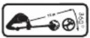 | Keep bystanders 15m away | IMPORTANT! When placing the chain on the guide bar, ensure the chain direction is the same as the image on the guide bar | ||
 | Sound power level | |||
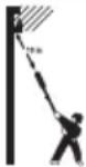 Electric shock can cause fatal injury. Keep a distance of at least 10m from power cables. Electric shock can cause fatal injury. Keep a distance of at least 10m from power cables. | ||||
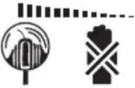 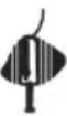 | The equipment continues to rotate! | |||
CARING FOR THE ENVIRONMENT
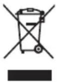
Tools that are no longer usable should not be disposed of with household waste but in an environmentally friendly way. Please recycle where facilities exist. Check with your local council authority for recycling advice.

Recycling packaging reduces the need for landfill and raw materials. Reuse of recycled material decreases pollution in the environment. Please recycle packaging where facilities exist. Check with your local council authority for recycling advice.
WARRANTY
IN ORDER TO MAKE A CLAIM UNDER THIS WARRANTY YOU MUST RETURN THE PRODUCT TO YOUR NEAREST BUNNINGS WAREHOUSE WITH YOUR BUNNINGS REGISTER RECEIPT. PRIOR TO RETURNING YOUR PRODUCT FOR WARRANTY PLEASE TELEPHONE OUR CUSTOMER SERVICE HELPLINE:
Australia 1800 069 486
New Zealand 0508 069 486
TO ENSURE A SPEEDY RESPONSE PLEASE HAVE THE MODEL NUMBER AND DATE OF PURCHASE AVAILABLE. A CUSTOMER SERVICE REPRESENTATIVE WILL TAKE YOUR CALL AND ANSWER ANY QUESTIONS YOU MAY HAVE RELATING TO THE WARRANTY POLICY OR PROCEDURE.
The benefits provided under this warranty are in addition to other rights and remedies which are available to you at law.
Our goods come with guarantees that cannot be excluded at law. You are entitled to a replacement or refund for a major failure and for compensation for any other reasonably foreseeable loss or damage. You are also entitled to have the goods repaired or replaced if the goods fail to be of acceptable quality and the failure does not amount to a major failure.
Generally you will be responsible for all costs associated with a claim under this warranty, however, where you have suffered any additional direct loss as a result of a defective product you may be able to claim such expenses by contacting our customer service helpline above.
5 YEAR REPLACEMENT WARRANTY
Your Product is guaranteed for a period of 60 months from the original date of purchase and is intended for DIY (Do It Yourself) use only. If a product is defective it will be replaced in accordance with the terms of this warranty. Lithium Ion batteries and chargers are covered by a 36 month warranty. Warranty excludes consumable parts, for example: line & spool, shoulder strap and included accessories.
WARNING
The following actions will result in the warranty being void.
• Professional, Industrial or high frequency use.
- If the tool shows signs of damage or defects caused by or resulting from abuse, accidents or alterations.
- Failure to perform maintenance as set out within the instruction manual.
- If the tool is disassembled or tampered with in any way.
• Professional, industrial or high frequency use.
OZITO Australia/New Zealand (Head Office) 25 Fox Drive,
Dandenong South, Victoria, Australia 3175.
- BRUSHLESS 4-IN-1 MULTI TOOL KIT
- GENERAL POWER TOOL SAFETY WARNINGS
- Work area safety
- Electrical safety
- Personal safety
- Power tool use and care
- Battery tool use and care
- Service
- LINE TRIMMER / BRUSH CUTTER SAFETY WARNINGS
- POLE HEDGE TRIMMER SAFETY WARNINGS
- POLE PRUNER SAFETY WARNINGS
- Kickback
- Push Back
- Pull Forward
- SPECIFICATIONS
- LINE TRIMMER
- BRUSH CUTTER
- POLE PRUNER
- POLE HEDGE TRIMMER
- EXTENSION POLE
- KNOW YOUR PRODUCT
- CONTENTS
- POWER TOOL SAFETY WARNINGS...... Page 2
- SPECIFICATIONS...... Page 7
- KNOW YOUR PRODUCT...... Page 8
- STEPUP & PREPARATION...... Page 11
- OPERATION...... Page 20
- APPLICATIONS......Page 22
- MAINTENANCE......Page 30
- TROUBLESHOOTING...... Page 35
- SPARE PARTS...... Page 36
- DESCRIPTION OF SYMBOLS...... Page 37
- WARRANTY...... Page 40
- SETUP & PREPARATION
- ASSEMBLY
- Fitting the Front Handle
- Fitting the Safety Guard
- SETUP & PREPARATION [cont.]
- LINE SPOOL
- Removing and Fitting the Line Spool
- BRUSH CUTTER BLADE
- Fitting and Removing the Brush Cutter Blade
- CHAIN & BAR
- Fitting the Guide Bar & Chain
- Tensioning the Chain
- Chain Lubrication
- ATTACHMENT
- Fitting and Removing Attachments
- To Remove Fitted Attachment:
- To Fit Selected Attachment:
- Fitting the Connecting Tube on the Motor Tube
- Fitting the Extension Pole
- SHOULDER STRAP
- Attaching the Shoulder Strap
- OPERATION
- BATTERIES
- Installing and Removing the Batteries
- SWITCHING ON/OFF
- Switching On
- Switching Off
- APPLICATIONS
- LINE TRIMMER/BRUSH CUTTER
- Extending the Cutting Line
- Trimming/Mowing
- Low Trimming & Mowing
- Cutting along Fences/Foundations/Trees
- Jamming
- Preventing Recoil
- APPLICATIONS [cont.]
- POLE PRUNER
- Chain Tension
- Safe Working
- Protective Clothing
- Pruning
- Limbing
- Sawing Techniques
- Cutting Wood Under Tension
- POLE HEDGE TRIMMER
- Adjusting the Angle
- Cutting New Growth
- Cutting the Sides of a Hedge
- Cutting the Top
- MAINTENANCE
- Replacing the Spool/Clearing Jams and Tangled Line
- Rewinding Spool from Bulk Line
- MAINTENANCE [cont.]
- Maintaining the Guide Bar
- WARNING! ALWAYS WEAR GLOVE WHEN HANDLING THE CHAIN AS IT IS VERY SHARP AND CAN CUT YOU WHEN IT IS NOT MOVING.
- Chain Sharpening
- Automatic Chain Lubrication
- Pole Hedge Trimmer Blade
- Cleaning, Storage and Transport
- Cleaning
- Storage
- Transport
- TROUBLESHOOTING
- SPARE PARTS
- Chain Replacement
- DESCRIPTION OF SYMBOLS
- CARING FOR THE ENVIRONMENT
- WARRANTY
- Australia 1800 069 486
- New Zealand 0508 069 486
- YEAR REPLACEMENT WARRANTY
- WARNING
- The following actions will result in the warranty being void.
Brand : Ozito
Model : PXGMTK-4182
Category : Hedge Trimmer