AT-7700 - Desktop computer FOXCONN - Free user manual and instructions
Find the device manual for free AT-7700 FOXCONN in PDF.

| Product Type | Desktop Computer |
| Brand | Foxconn |
| Model | AT-7700 |
| Form Factor | Mid-Tower |
| Dimensions (W x D x H) | 180 x 450 x 430 mm (approx.) |
| Weight | 10 kg (approx.) |
| Power Supply | 300W ATX |
| Motherboard Form Factor | Micro-ATX |
| Processor Socket | LGA 775 |
| Maximum Memory | 4 GB DDR2 |
| Storage Bays | 2 x 3.5", 2 x 5.25" |
| Expansion Slots | 3 x PCI, 1 x PCI-E x16 |
| Front I/O Ports | 2 x USB 2.0, Audio |
| Rear I/O Ports | 4 x USB, VGA, LAN, Audio |
| Operating System | Windows XP / Vista (pre-installed) |
| Cleaning Instructions | Use a soft dry cloth; avoid liquids |
| Safety Warnings | Keep away from water and heat sources |
| Spare Parts Availability | Contact authorized service centers |
Frequently Asked Questions - AT-7700 FOXCONN
User questions about AT-7700 FOXCONN
0 question about this device. Answer the ones you know or ask your own.
Ask a new question about this device
Download the instructions for your Desktop computer in PDF format for free! Find your manual AT-7700 - FOXCONN and take your electronic device back in hand. On this page are published all the documents necessary for the use of your device. AT-7700 by FOXCONN.
USER MANUAL AT-7700 FOXCONN
natural_image
Back view of a black and white electronic device rear panel with ports, buttons, and ventilation slots (no readable text or symbols)NanoPC
User's Manual
Trademark:
All trademarks are the property of their respective owners.
Version:
User's Manual V1.0 for NanoPC.
Symbol description:

Refers to important information that can help you to use NanoPC better, and tells you how to avoid problems.

n: Indicating a potential risk of hardware damage or physical injury may exist.

e of this symbol indicates that this product may not be treated as household waste. By ensuring this product is disposed of correctly, you will help prevent potential negative consequences for the environment and human health, which could otherwise be caused by inappropriate waste handling of this product. For more detailed information about recycling of this product, please contact your local city office, your household waste disposal service or the shop where you purchased this product.
© All rights reserved.
All trade names are registered trademarks of respective manufacturers listed.
All images are for reference only, please refer to the physical product for specific features.
Safety Notice:

Before using this product, please read the below safety notice carefully, this will help to extend the product's lifecycle, and work normally.
- When NanoPC is working, please make sure its ventilation system is working.
The power adapter is dissipating heat during normal use, please be sure not to cover it and keep it away from your body to prevent discomfort or injury by heat exposure. - Please use the power adapter that comes with the product's package, wrong power adapter may damage your device.
■ Make sure all the peripherals are properly connected before using NanoPC.
This product should only be used in an environment with ambient temperatures between 0°C and 40°C.
■ Always shut down the computer before installing or uninstalling the peripheral which does not support hot plug.
■ Disconnect all peripherals before servicing or disassembling this equipment.
Please do not disassemble this product by yourself, any disassembly not approved by the original manufacturer may result in malfunction, and void warranty. - Risk of explosion if battery is replaced by an incorrect type, please dispose of used batteries according to the instructions.
Package Contents
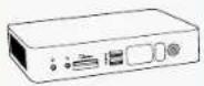 |  | 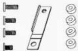 |
| NanoPC Seat Base | Screws, Mini PCIe Half Card Support Bracket, Magnet Rubber Foot | |
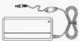 | 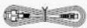 |  |
| Power Adapter Power Cord Easy Guide | ||
| USB Flash Disk DVI-VGA Adapter | ||

We DO NOT guarantee it is in compliance with the Safety Certificates if you add on an extension cable to NanoPC USB Flash Disk in the package.
TABLE OF CONTENTS
Introduction
1-1 Front Side View 2
1-2 Back Side View....4
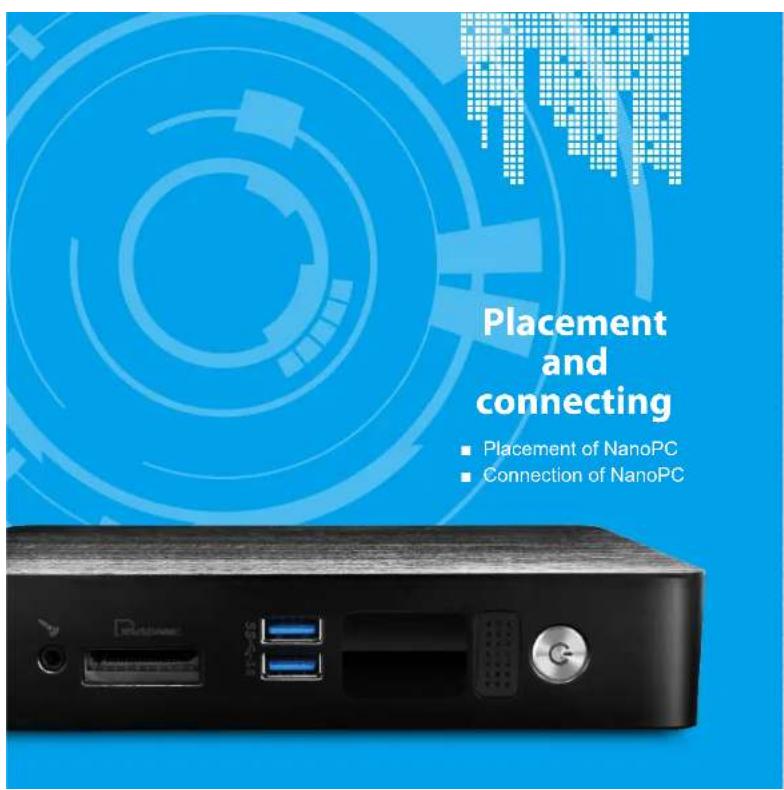
Placement and connecting
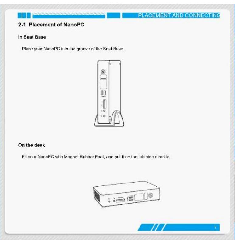
2-1 Placement of NanoPC 7
In Seat Base 7
On the desk 7
2-2 Connection of NanoPC 8
Connect display 8
Connect USB devices....9
Connect network cable....9
Connect power cord 10
BIOS Setup
Enter BIOS Setup 12
Main 13
Advanced 14
Miscellaneous....15
Integrated Peripherals 16
SATA Configuration 17
Power....19
Security 20
BootOptions....21
Save & Exit 23
Install OS
4-1 Install Windows 7/8....26
4-2 Install Drivers....30
Utility
Fox WINFLASH 32
- Local Update .... 32
- About & Help....34
natural_image
Front view of a white electronic device rear panel with ports and indicators (no readable text or symbols)
Introduction
Front Side View
■ Back Side View
INTRODUCTION INTRODUCTION
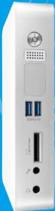
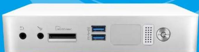
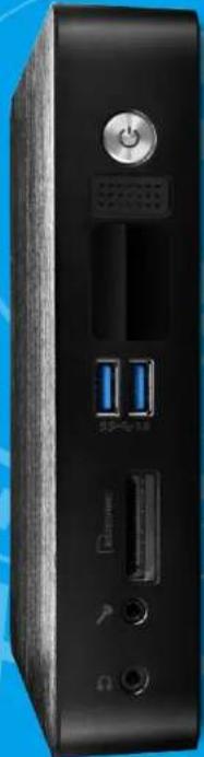
1-1 Front Side View
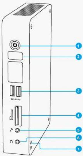
| 1 Powder button with Power indicator LEDPress to turn your NanoPC on or off, the LED can indicate your system states. | |
| 2 Speaker | |
| 3 SS+0-3.0 | USB 3.0 portThis USB port supports the USB 3.0/2.0/1.0 specification. Use this port for USB devices such as keyboard, mouse, USB printer, USB flash drives and hard disk drives, etc.As to Windows 7 system, you need to install the USB 3.0 driver in NanoPC USB Disk before using it. |
| 4 WINDAMC | Multi-Function card readerThis memory card reader supports SD/SDHC/SDXC/MS/MS Pro/MMC memory cards used in devices like digital cameras, mobile phones, Media players and so on. |
| 5 ↗ | Microphone / SPDIF in portConnects to a microphone or playback devices with optical connectors (3.5mm jack).SPDIF function requires additional adapter and adapter cable. |
| 6 ↩ | HeadphoneConnects to a headphone. |
| 7 Kensington lock | |
| Attach a Kensington security system or a compatible security lock to secure your NanoPC in place. | |

INTRODUCTION INTRODUCTION
1-2 Back Side View
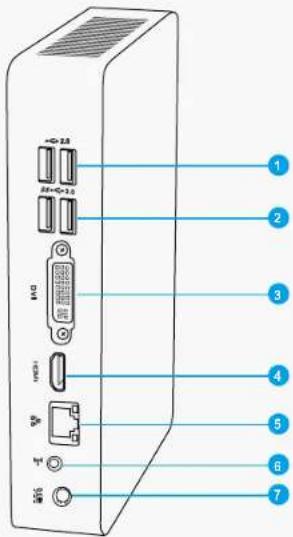
1 USB2.0 port
This USB port supports the USB 2.0/1.0 specification. Use this port for USB devices such as keyboard, mouse, USB printer, USB flash drives and hard disk drives, etc.
| 2 | SB+6+3.0 | USB 3.0 portThis USB port supports the USB 3.0/2.0/1.0 specification. Use this port for USB devices such as keyboard, mouse, USB printer, USB flash drives and hard disk drives, etc.As to Windows 7 system, you need to install the USB 3.0 driver in NanoPC USB Disk before using it. |
| 3 | DMI | DVI portConnect monitor or TV that uses DVI connector to this port.By using the DVI to VGA adapter that comes with your product, you can also connect a VGA-compatible devices such as a monitor or projector. |
| 4 | HDMI | HDMI portThe HDMI (High-Definition Multimedia Interface) port supports Full-HD display devices.Connect monitor or TV that uses HDMI connector to this port. |
| 5 | 品品 | RJ-45 LAN portSupports 10/100/1000Mb/s Ethernet network.Connect network cable to access Internet. |
| 6 | ( 回回) | Line out / SPDIF out portConnects to powered analog speakers or recording devices with optical connectors (3.5mm jack).SPDIF function requires additional adapter and adapter cable. |
| 7 | OGIM | Power input portConnect power cord that come with your product. |

PLACEMENT AND CONNECTING PLACEMENT AND CONNECTING
2-2 Connection of NanoPC
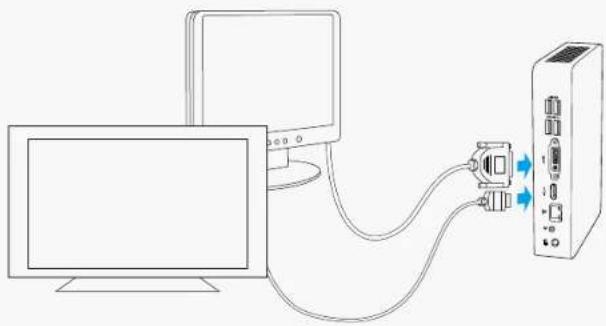
Connect display
Connect a display or TV that has HDMI port or VGA port to your NanoPC.
You can connect a VGA display to the DVI port by using the DVI-VGA adapter.
natural_image
Line drawing of a computer connected to a server via cable (no text or symbols)
Please use the customized DVI-VGA Adapter that comes with your NanoPC to get a higher resolution on your VGA display.
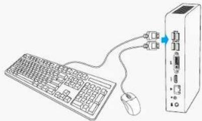
Connect USB devices
Connect USB devices to the USB ports, for example, mouse, keyboard devices.
As to Windows 7 system, you need to install the USB 3.0 driver in NanoPC USB disk before using the USB 3.0 ports.
natural_image
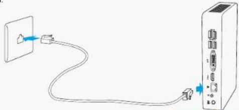
Line drawing of a computer setup with a keyboard, mouse, and server unit (no text or symbols)Connect network cable
Connect one end of a network cable to the RJ-45 LAN port, and the other end to a hub or switch.
natural_image
Simple line drawing of a cable being inserted into a device (no text or symbols)8
9
PLACEMENT AND CONNECTING
Connect power cord
Connect the power adapter to the power input port of the NanoPC, and then press the power button to start it.
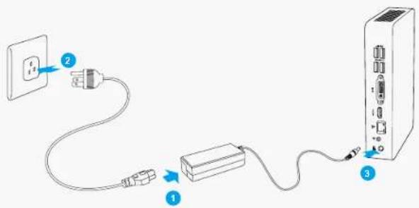

The power adapter is dissipating heat during normal use, please do not cover it and keep it away from your body to prevent injury from heat exposure.
natural_image
Front view of a white electronic device rear panel showing ports, indicators, and a G button (no readable text or symbols)
natural_image
Abstract blue and white pixelated graphic with no text or symbolsBIOS Setup
Enter BIOS Setup
Main
■ Advanced
Power
■ Security
BootOptions
Save & Exit
BIOS SETUP BIOS SETUP
Enter BIOS Setup
The BIOS is the communication bridge between hardware and software, correctly setting up the BIOS parameters is critical to maintain optimal system performance. Power on the computer, when the message
"Press to enter setup. Press
appears at the bottom of the screen, you can press key to enter Setup.

We do not suggest that you change the default values in the BIOS Setup, and we shall not be responsible for any damage which resulted from the change you made.
Use the arrow right/left keys to select a specific function and go to the submenu. Each function is explained below:
Main
It displays the basic system configuration, such as CPU Name, memory size, system date, time and so on. They all can be viewed or set up through this menu.
Advanced
The advanced system features can be set up through this menu.
Power
All the items related with Green function features can be setup through this menu.
Security
The Administrator/User password can be set up through this menu to prevent unauthorized use of your computer. If you set a password, the system will ask you to key in correct password before boot or access to Setup.
BootOptions
Boot features can be set up through this menu. You can set the boot device priority and enable "Quiet Boot" feature here.
Save&Exit
The optimal performance settings can be loaded through this menu. However, it may offer better performance in some ways (such as less I/O cards, less memory ...etc.), still, it may cause problem if you have more memory or I/O cards installed. It means, if your system loading is heavy, set to optimal default may sometimes come out an unstable system. What you need now is to adjust BIOS setting one by one, trial and error, to find out the best setting for your current system. You also can save or discard the changes and exit BIOS setup here.
12 13
Main
![Apple Specific utility - Copyright (C) 2012 American Navigation, Inc. Help Advanced Power Security Readings Save & Exit System Name Project Version: C2012/2012 Build Date: 11/23/2012 BC Version: 26.54.01 Processor Initiate/IO: Diver M1.15 S1070 CP Core frequency: 1.72 Hz Count: 1 Channel: Intel PCR No. Base BIOS System Memory Memory Frequency: BIOS No. System Memory Size: 4096 MB (CD83) System Base [Mod 1 / 2012/2012] System Type [D-80E-1] Active Level: Accelerator Name: New Description: Select File Edit As... File Set File General Help File Previous Help File Last Load Results File Last Load Input File Last Load Correct Results File Last Load Default version 2-15, 1971, Open-Target (C) 2012 American Navigation, Inc.](/content/2026/05/1055507/images/4e94537c2fbd0b373f306717cb883ec0d995c4ee9942eedb91b037652d6dcac1.jpg)
▶ System Date
Day—weekday from Sun. to Sat., this message is automatically displayed by BIOS (Read Only).
Month—month from 1 to 12.
Date—date from 1 to 31
Year—year, set up by users.
Use [ENTER], [TAB] or [SHIFT-TAB] to select a field. Use [+] or [-] to input the value.
▶ System Time
This item allows you to configure the desired time. Use [ENTER], [TAB] or [SHIFT-TAB] to select a field. Use [+) or [-] to input the value.
The three fields of the setting are
▶ Access Level
It displays your current access level. If you enter system with a user password, it will display "User". If
BIOS SETUP BIOS SETUP
no password is set or you enter system with administrator password, this item will display "Administrator".
Advanced
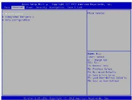
▶ Miscellaneous/Integrated Peripherals/SATA configuration Press
Miscellaneous
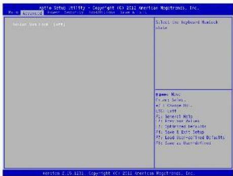
▶ Bootup Num-Lock This item defines if the keyboard Num Lock key is active when your system is started. The available settings are: On and Off (default).
BIOS SETUP BIOS SETUP
Integrated Peripherals
![Windows Setup Utility - A Copyright (C:) 2002 American Postcards, Inc. Post Advanced: "Press" Security Postcards Save Clear WIN Active Configuration [1] [Book/Win] CPU Control for Configuration CPU Controller (Inscribed) Context Destination of the Active Device Stacked as "Access" to the application by Advanced Enabled as "Access" will an application by Limited Name: Max Index Select = 3 Charge Spk DPC Last File Manager Help File Preview Answer File Registered Defaults File Save & Lett Setup File Load User-Price Default& File Save on User-defined Version 1.15.201 Copyright (C:) 2002 American Postcards, Inc.](/content/2026/05/1055507/images/9357bba8d6ff9e3c1999174b70e69ebc04b05878fa7c83f6e07c14d385b8ed23.jpg)
▶ Azalia
This item is used to control the detection of Azalia device.
▶ CIR Controller
This item is used to enable or disable the CIR controller.

SATA Configuration
![SATA Status Utility Copyright (C:) 2017 American Progressors, Inc. Base: Advanced Power Security Contributions Save & Help SATA Status Utility [Standard] SATA Status Solution [MST] Port 0 [Disabled] Port 1 [Disabled] Installable Rapid Start Technology Installable Rapid Start Technology [ClosedNote] Enable or optional SATA Device. Name: P#e Enter Select FPC: Through Spl. FPC: 100% FPC General: 10 p P2: Previous Values PFC: Business Definition PFC: Base A: Unit Design PFC: Load User Defined Defaults PFC: Save As User Default Function 2.5.1971 Copyright (C:) 2017 American Progressors, Inc.](/content/2026/05/1055507/images/656149bf79f269cd59d2db856d25d24d0c5b2612beda00419ab165d4c54a7f10.jpg)
▶ SATA Mode Selection
This item is used to set the operation mode of your SATA ports.
[IDE] - This configures the SATA ports to support IDE mode.
[AHCI] - The Advanced Host Controller Interface (AHCII) specification describes the register level interface for a Host Controller for Serial ATA. The specification includes a description of the hardware/software interface between system software and the host controller hardware. AHCI provides more advanced features including SATA features, but some SATA drives may not support AHCI, unless they are labeled with AHCI support in its specification.
[AHCI] - The Advanced Host Controller Interface (AHCII) specification describes the register level interface for a Host Controller for Serial ATA. The specification includes a description of the hardware/software interface between system software and the host controller hardware. AHCI provides more advanced features including SATA features, but some SATA drives may not support AHCI, unless they are labeled with AHCI support in its specification.
If your motherboard supporting AHCI, and you have a SATA device, which also supports AHCI, then

BIOS SETUP BIOS SETUP
you can select IDE option to have fair performance, or you can select AHCI to get its best performance.
▶ Port 0/Port 1
This item is used to enable or disable SATA port 0/1.
▶ Intel(R) Rapid Start Technology
This item is used to enable or disable the Intel(R) Rapid Start Technology.
Power
![File Setup authority - Copyright ©10.2012 American Navigation, Inc. Main Advanced Power Security Subscriptions Save & Exit Name: All (See Note / Work Table) Help Sleep Support / [Sub-act] Use the restore on 4G power Data Function. Name: New Options Select [ ] Change Data... [ ] File List [ ] General Help [ ] Previous Results [ ] Last User Details [ ] Save Email Setup [ ] Load User Required Details [ ] Save or Back-defined Revision 2013: Copyright ©10.2012 American Navigation, Inc.](/content/2026/05/1055507/images/764d9d91b12024e345ea3f9bf2e1165f015607f76a4d663d0aa2f01db8c91b0c.jpg)
▶ Restore on AC Power Loss
This item is used to set which state the PC will take with when it resumes after an AC power loss.
▶ Deep Sleep Support
This item is used to enable or disable Deep Sleep Support function. When entering deep sleep mode system(S4/S5) only can wake up from power button.
▶ Lan Wakeup
This item is used to enable or disable LAN wakeup function. It appears only when the "Deep Sleep Support" is disabled.
BIOS SETUP BIOS SETUP
Security
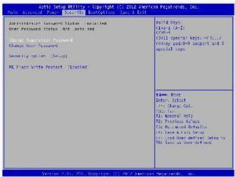
▶ Change Supervisor Password
This item is used to install or change supervisor password.
▶ Change User Password
This item is used to install or change user password.
Only when there exists an Administrator password, then this setting can be activated.
▶ Security option
To protect the BIOS from being changed by the unauthorized users, there is a security option provided for your choice. Only when there exists an Administrator password, then this setting can be activated.
[setup]: A password will be required to enter the BIOS. (Only check password when enter setup)
[Always]: A password will be required to enter both the system and BIOS. (Always check password)
▶ ME Flash Write Protect
To protect the ME BIOS, there is a ME BIOS write-protection mechanism provided to prevent BIOS FLASH tool being improperly used to update ME BIOS.
BootOptions
![License Support, Utility - Copyright (C) 2012 American Navigation, Inc. Main Advanced Power Security Description Save & Back Launch CCR License Launch PCI Open Policy [I'm not Launch] FIXED BOOT ORDER PRIATIVES Jack Boot Device [Mand Disc] Back Boot Device [FOMO] Back Boot Device [Executive Deuters] [Off Boot Device] [AIS] • Back Boot Drive Priority, [Press Alter] • DevOps Use Drive Priority, [Press Alter] • Remote Boot Device Priority, [Press Alter] • McAvon Boot Device Priority, [Press Alter] Diet Boot [Tabled] Boot No. [Bus1.d] Please Note Details Select [Off Course Bc... File Set] [Off General Help] [Off Previous Refins] [Off Sub Incl Benefits At Issue E-1/4: Webt] [Off Load User Method Rights For Load or Load-defined]](/content/2026/05/1055507/images/5f8846a6ec2879ef159a78581890c52543f65dfa05b80f372f7be13c431cabe2.jpg)
▶ Launch CSM
This item controls if CSM will be launched.
WARNING: This option is for advanced users.
▶ Launch PXE OpROM policy
This item controls the execution of Legacy PXE OpROM.
▶ 1st/2nd/3rd/4th Boot Device
These items are used to set the system boot order.
▶ Hard Disk Drives BBS Priorities/Optical Disk Drive BBS Priorities/Removable Device BBS Priorities/
NETWORK Device BBS Priorities
Press
▶ Quiet Boot
This item is used to enable/disable the quiet boot.
BIOS SETUP BIOS SETUP
[Disabled] : Displays the normal POST messages.
[Enabled] : Displays OEM customer logo instead of POST messages.
▶ Boot Menu
This item is used to enable or disable boot menu.
Save & Exit
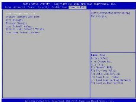
▶ Save Changes and Exit
If you select this option and press
Select [Yes] to save your changes and exit, select [No] or
▶ Discard Changes and Exit
If you select this option and press
Select [Yes] to exit setup utility without saving your modifications, select [No] or
▶ Save Changes
If you select this option and press
▶ Discard Changes
If you select this option and press
▶ Load Default Values
BIOS SETUP
Optimal defaults are the best settings of this motherboard.
Always load the Optimal defaults after updating the BIOS or after clearing the CMOS values.
Select this option and press Enter, it will pop out a dialogue box to let you load the defaults. Select
By this default, BIOS have set the optimal performance parameters of system to improve the performances of system components. But if the optimal performance parameters to be set cannot be supported by your hardware devices (for example, too many expansion cards were installed), the system might fail to work.
▶ Save as User Default Values
If you select this option and press
Select [Yes] to save the changes done so far as user defaults, select [No] or
menu
▶ Load User Default Values
If you select this option and press
Select [Yes] to restore/load the user defaults to all the setup options, select [No] or
natural_image
Back view of a black desktop computer tower with ports and indicator lights (no visible text or labels)
natural_image
Abstract blue pixelated graphic with no text or symbolsInstall OS
■ Install Windows 7/8
Install Drivers
INSTALL OS INSTALL OS
What kinds of hardware and software you need here:
- Windows 7/8 Install USB Disk / USB DVD-ROM drive and Windows 7/8 Install CD (Other purchase)
- NanoPC USB Flash Disk (In this package)

Windows 7(32-bit/64-bit) and Windows 8(32-bit) can't be installed when "Launch CSM" is set to "Disabled" in the BIOS setup.
4-1 Install Windows 7/8
- Connect the Windows 7/8 Install USB Disk (or USB DVD-ROM drive) to one USB port of NanoPC.
- Press power on button to turn on your computer.
- Put the Windows 7/8 Install CD into the USB DVD-ROM drive if you use the USB DVD-ROM drive.
- Computer will choose the boot device by BIOS default and start loading the files for installing the OS.

Please press key to enter BIOS Setup if you want to change the first boot device for installing the OS.
- When the installation windows popup, set the related items and click "Next" to continue, then click "Install now" button to start the setup.
- When the license terms appear, choose accept and click "Next" to continue.
- It will then ask you to select the installation type. Click "Custom (advanced)" to install a new copy of Windows.
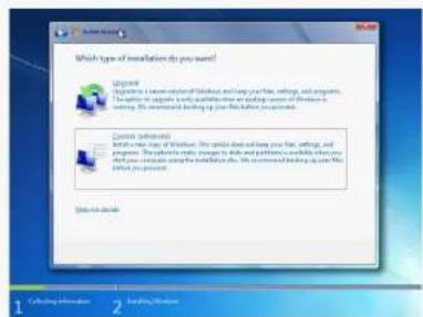
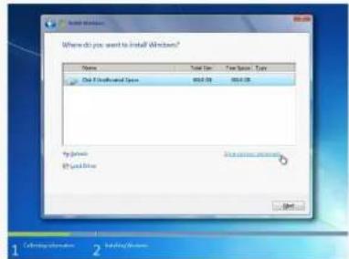
- The setup will display the hard disk partitions (160GB, in this example) of your system. If there were other systems (such as Linux) installed previously, you need select them and click "Drive options (advanced)" to delete them. When all partitions are clean, setup will display the biggest size of your hard drive.
INSTALL OS INSTALL OS
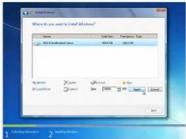
- In the hard disk size screen, you can click the "new" button to create partitions as you need.
In this example we are creating a 70GB partition to install Windows. Make your modifications and click "Apply".
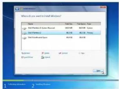
To ensure that all Windows features work correctly, Windows might create additional partitions for system files. So you will see a 100MB partition reserved by system after you create a partition. Select the 70GB partition and click "Next" to continue.
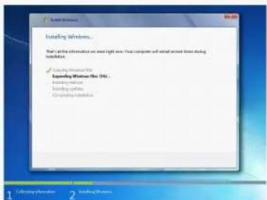
- The setup program will then start to install Windows 7/8 on your hard disk. During the installation, your computer will restart several times.

INSTALL OS
- When the installation is complete, setup will prepare your computer for it's first use. You can then follow the steps to select system settings, create an account, set a password...etc, until the whole process is completed.
4-2 Install Drivers
- When the Windows 7/8 is completely installed, you have to install the necessary drivers before using the NanoPC. Connect the NanoPC USB Flash Disk to your system.
- Waiting for a few seconds, the main menu will be displayed on the screen.
- Use these options to install all the drivers for your system. You must click "Intel Chipset Driver" to install it first. After that, you can click "One Click Setup" and then choose the items you want to install, or you can click on each individual driver to install it manually.
- After installing all the drivers, you need to restart your NanoPC, then you can start using it.
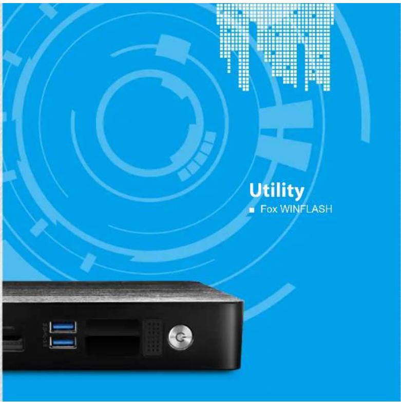
UTILITY UTILITY
Fox WINFLASH
Fox WINFLASH is a useful utility to backup and update your system BIOS.
Supporting Operating Systems:
■ Windows 7 (32-bit/64-bit)
■ Windows 8 (32-bit/64-bit)
1. Local Update
1-1 Local Update - BIOS Information
This page lets you know your system BIOS information.
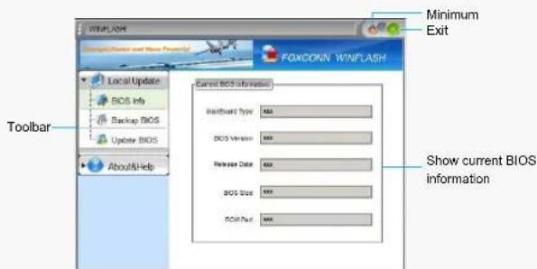
Note: BIOS Size 32Mb = 32M bit = 4M Byte
BIOS Size 16Mb = 16M bit = 2M Byte
Please refer to the physical motherboard for details.
32 33

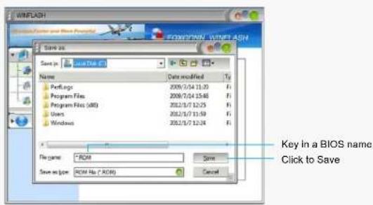
1-2 Local Update - Backup BIOS
This page can back up your system BIOS. You can click "Backup BIOS", and key in a file name, then click "Save" to finish the backup operation. The extension of this backup file is "ROM" for AMI BIOS. Make sure you can remember the file name together with the directory which it is stored, prevented that you may need them to recover your BIOS later.
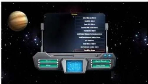
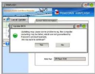
1-3 Local Update - Update BIOS
This page helps you to update your BIOS from a local file. After click "Update BIOS", An alert message will be displayed to ensure if you really want to continue, click "Yes" to confirm. A setup wizard will guide you to load a local BIOS file to finish the operation. You must remember from which directory to load your new BIOS file (with an extension of ".ROM" for AMI BIOS) before the setup wizard starts.
UTILITY
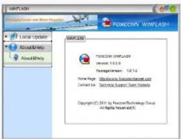
2. About & Help
This page shows some information about Fox WINFLASH.
34
[Non-Text]
Statement:
This device complies with part 15 of the FCC Rules. Operation is subject to the following two conditions: (1) This device may not cause harmful interference, and (2) this device must accept any interference received, including interference that may cause undesired operation.
Warning:
FEDERAL COMMUNICATIONS COMMISSION INTERFERENCE STATEMENT
This equipment has been tested and found to comply with the limits for a Class B digital device, pursuant to part 15 of the FCC Rules. These limits are designed to provide reasonable protection against harmful interference in a residential installation. This equipment generates, uses and can radiate radio frequency energy and, if not installed and used in accordance with the instructions, may cause harmful interference to radio communications. However, there is no guarantee that interference will not occur in a particular installation. If this equipment does cause harmful interference to radio or television reception, which can be determined by turning the equipment off and on, the user is encouraged to try to correct the interference by one or more of the following measures:
- Reorient or relocate the receiving antenna.
- Increase the separation between the equipment and receiver.
- Connect the equipment into an outlet on a circuit different from that to which the receiver is
connected. - Consult the dealer or an experienced radio/ TV technician for help.
Caution:
Any changes or modifications not expressly approved by the grantee of this device could void the user's authority to operate the equipment.
RF exposure warning:
This equipment must be installed and operated in accordance with provided instructions and the antenna(s) used for this transmitter must be installed to provide a separation distance of at least 20cm from all persons and must not be co-located or operating in conjunction with any other antenna or transmitter. End-users and installers must be provide with antenna installation instructions and transmitter operating conditions for satisfying RF exposure compliance.
Warning statement for Europe:
Also, put in the manual which directive to fulfil and also which countries to sell the product.
Example of a text to tell which directive has been fulfilled:
Hereby, Foxconn, declares that this AT-7000 Series is in compliance with the essential requirements
and other relevant provisions of Directive 1999/5/EC."