
AquaLink M8 - Pool Controller ZODIAC - Free user manual and instructions
Find the device manual for free AquaLink M8 ZODIAC in PDF.

| Product Type | Pool and Spa Control System |
| Brand | Zodiac |
| Model | AquaLink M8 |
| Power Supply | 240 VAC, 50 Hz, 2.5 A |
| Contact Rating (Mains) | 25 A, 3 HP @ 240 VAC, 1500 W incandescent |
| Extra Low Voltage | 24 VAC, 1 A (Class 2) |
| Control Panel Types | OneTouch and PDA Handheld Remote |
| Maximum Indoor Control Panels | 4 |
| Temperature Sensors | Water, Air, Solar (optional) |
| Valve Actuators | Jandy Pro Series (JVA), up to 2 (intake/return) |
| Variable Speed Pump Support | Jandy ePump, Pentair IntelliFlo VS/VF, IntelliPro VS |
| Heater Compatibility | Gas, Heat Pump, Solar (via DIP switch) |
| Freeze Protection | Yes, programmable temperature and assigned devices |
| Programming Features | Timed on/off, seasonal adjust, maintain temperature, variable speed pump schedules |
| Auxiliary Equipment | 8 AUX circuits (AUX1-8) with customizable labels |
| Light Control | Color lights (Alpine White, Sky Blue, etc.) with 8 presets |
| Communication | RS485 for variable speed pump; RF 900 MHz for PDA remote |
| Mounting Distance | At least 3.5 m from pool/spa, 1.5 m off ground |
| DIP Switch Configuration | S1 (8 switches) and S2 (4 switches) for cleaner, spillover, heat pump, etc. |
| Package Contents (OneTouch PDA System) | OneTouch Control Panel, Power Centre, 2 Temp Sensors, 2 JVAs (for combo), PDA Handset with batteries, Outdoor Transceiver J-box |
| Safety Compliance | AS/NZS 3000, bonding, RCD required |
Frequently Asked Questions - AquaLink M8 ZODIAC
User questions about AquaLink M8 ZODIAC
0 question about this device. Answer the ones you know or ask your own.
Ask a new question about this device
Download the instructions for your Pool Controller in PDF format for free! Find your manual AquaLink M8 - ZODIAC and take your electronic device back in hand. On this page are published all the documents necessary for the use of your device. AquaLink M8 by ZODIAC.
USER MANUAL AquaLink M8 ZODIAC

AquaLink® M8
For One Touch and PDA control systems
WARNING
FOR YOUR SAFETY - This product must be installed and serviced by a licensed electrician in accordance with the latest, enforced version of AS/NZS 3000 and any other applicable local installation codes. Before installing this product, read and follow all warning notices and instructions that accompany this product. Failure to follow warning notices and instructions may result in property damage, personal injury, or death. Improper installation and/or operation will void the warranty.
Improper installation and/or operation can create unwanted electrical hazard which can cause serious injury, property damage, or death.
EQUIPMENT INFORMATION RECORD
DATE OF INSTALLATION
INSTALLER INFORMATION
INITIAL PRESSURE GAUGE READING (WITH CLEAN FILTER)
PUMP MODEL HORSEPOWER
FILTER MODEL
CONTROL PANEL MODEL SERIAL NUMBER
NOTES:
Table of Contents
Section 1. Important Safety Instructions.....4
Section 2. System Overview....6
2.1 Package Contents....6
2.2 Electrical Specifications....6
2.3 Materials and Tools 6
2.4 Basic Plumbing....7
Section 3. Installation....11
3.1 Power Center Mounting.... 11
3.2 High Voltage Wiring....11
3.3 Heater Connection 13
3.4 Temperature Sensors....13
3.5 Jandy Valve Actuators....14
3.6 OneTouch™ Control Panel....17
Section 4. System Startup.... 19
4.1 OneTouch Programming ..... 19
4.2 OneTouch Reset and Display Messages .....21
4.3 Variable Speed Pump Menu....21
4.4 OneTouch™ Systems Defaults and General Modes ..24
4.5 PDA Installation....24
4.6 PDA Handheld Remote System Defaults and General Modes....26
4.7 PDA Handheld Remote On/Off Menu....27
4.8 Pool Heat....28
4.9 Spa Heat 28
4.10 Solar Heat 29
4.11 Auxiliary Equipment 29
4.12 Heat Pump 29
4.13 Set Light Colors....30
4.14 Variable Speed Pump....31
Section 5. PDA Handheld Remote Menu Flow Diagrams ...... 32
Section 6. OneTouch™ Menu Flow Diagrams ...... 33
Section 7. Troubleshooting....34
Section 8. Power Center Wiring Diagram for Combos and Onlys....35
Section 9. Power Center PCB DIP Switch Settings....36
9.1 DIP Switch Functions .....36
9.2 DIP Switch Settings for Pool and Spa Combination....37
9.3 DIP Switch Settings for Pool or Spa Only 38
9.4 DIP Switch Settings for Heat Pump Installation .....39
Section 10. General, Water Feature and Light Aux Labels....40
Section 1. Important Safety Instructions
READ AND FOLLOW ALL INSTRUCTIONS
The Aqualink control system is for Pool and Spa applications only. NOT FOR USE with anything other than Pool and Spa equipment.
All electrical work must be performed by a licensed electrician and conform to all national, state, and local codes. When installing and using this electrical equipment, basic safety precautions should always be followed, including the following:
DANGER
To reduce the risk of severe injury or death, do not remove the suction fittings of your spa or hot tub. Never operate a spa or hot tub if the suction fittings are broken or missing. Never replace a suction fitting with one rated less than the flow rate marked on the equipment assembly.
WARNING
Prolonged immersion in hot water may induce hyperthermia. Hyperthermia occurs when the internal temperature of the body reaches a level several degrees above the normal body temperature of 37^ C ( 98.6^ F). The symptoms of hyperthermia include dizziness, fainting, drowsiness, lethargy, and an increase in the internal temperature of the body. The effects of hyperthermia include: 1) unawareness of impending danger; 2) failure to perceive heat; 3) failure to recognize the need to exit spa; 4) physical inability to exit spa; 5) fetal damage in pregnant women; 6) unconsciousness resulting in a danger of drowning.
WARNING
To Reduce the Risk of Injury -
a) The water in a spa should never exceed 40^ C ( 104^ F). Water temperatures should remain between 38^ C ( 100^ F) and 40^ C ( 104^ F). The water in a spa should never exceed 40^ C ( 104^ F). Water temperatures between 38^ C ( 100^ F) and 40^ C ( 104^ F) are considered safe for a healthy adult. Lower water temperatures are recommended for young children and when spa use exceeds 10 minutes.
b) Since excessive water temperatures have a high potential for causing fetal damage during the early months of pregnancy, pregnant or possibly pregnant women should limit spa water temperatures to 38^ C ( 100^ F). Before entering a spa or hot tub, the user should measure the water temperature with an accurate thermometer since the tolerance of water temperature-regulating devices varies.
d) The use of alcohol, drugs, or medication before or during spa or hot tub use may lead to unconsciousness with the possibility of drowning.
e) Obese persons and persons with a history of heart disease, low or high blood pressure, circulatory system problems, or diabetes should consult a physician before using a spa.
f) Persons using medication should consult a physician before using a spa or hot tub since some medication may induce drowsines while other medication may affect heart rate, blood pressure, and circulation.
WARNING
Risk of electric shock - Install the controller at least 3.5 metres from the inside wall of the pool and/or hot tub using non-metallic plumbing.
Children should not use spas or hot tubs without adult supervision.
Do not use spas or hot tubs unless all suction guards are installed to prevent body and hair entrapment.
People using medications and/or having an adverse medical history should consult a physician before using a spa or hot tub.
WARNING
To avoid injury ensure that you use this control system to control only packaged pool/spa heaters which have built-in operating and high limit controls to limit water temperature for pool/spa applications. This device should not be relied upon as a safety limit control.
WARNING
People with infectious diseases should not use a spa or hot tub.
To avoid injury, exercise care when entering or exiting the spa or hot tub.
Do not use drugs or alcohol before or during the use of a spa or hot tub to avoid unconsciousness and possible drowning.
Before entering a spa or hot tub, measure the water temperature with an accurate thermometer.
Do not use a spa or hot tub immediately following strenuous exercise.
Prolonged immersion in a spa or hot tub may be injurious to your health.
Do not permit any electric appliance (such as a light, telephone, radio, or television) within 3.5 metres of a spa or hot tub.
The use of alcohol, drugs or medication can greatly increase the risk of fatal hyperthermia in hot tubs and spas.
Water temperature in excess of 38^ C ( 100^ F) may be hazardous to your health.
WARNING
A terminal bar marked "GROUND" is provided within the controller. To reduce the risk of electrical shock which can cause serious injury or death, connect this terminal bar to the grounding terminal of your electric service or supply panel with a continuous copper conductor having green insulation and one that is equivalent in size to the circuit conductors supplying this equipment in accordance with the latest, enforced version of AS/NZS 3000 and any other applicable local installation codes. In addition, where required, bonding should be extended in accordance with the latest, enforced version of AS/NZS 3000 and any other applicable local installation codes to any metal ladders, water pipes, or other metal within 3.5 m of the pool/spa.
CAUTION
Power to the Aqualink should be supplied by an isolating transformer or through a residual current device (RCD) with a rated residual operating current not exceeding 30mA.

Attention Installer: Install to provide drainage of compartment for electrical components.
SAVE THESE INSTRUCTIONS
Section 2. System Overview
2.1 Package Contents
Package contents will vary depending on which
AquaLink configuration you are installing.
| OneTouchTM PDA System | |
| • OneTouch Control Panel• AquaLink M8 Power Centre• Two (2) Temp Sensors• Two (2) JVAs (Pool/Spa Combo Systems) | • PDA Handset with batteries• Outdoor Transceiver J-box• AquaLink M8 Power Centre• Two (2) Temp Sensors• Two (2) JVAs (for pool/spa combo systems) |
2.2 Electrical Specifications
Power Supply 240 VAC; 50 Hz; 2.5 A
Contact Rating Mains Voltage - 25 A;
3HP @ 240 VAC
1500 Watts Incandescent
Extra Low Voltage - Class 2,
1 A @ 24 VAC
2.3 Materials and Tools
Installation Materials Furnished
- Screw Set (includes Plastic Anchors)
• Metal Mounting Bracket - Power Drill
- 3/16" Drill Bit - Hammer Drill Bit (only necessary to drill into brick or concrete)
- Conduit Fittings
- Wire Nuts
- Wire Crimping Pliers
- Pencil or Marking Pen
- Flat Head Screwdriver
• Phillips Head Screwdriver - Small Flathead or Slotted Screwdriver
Dimensions
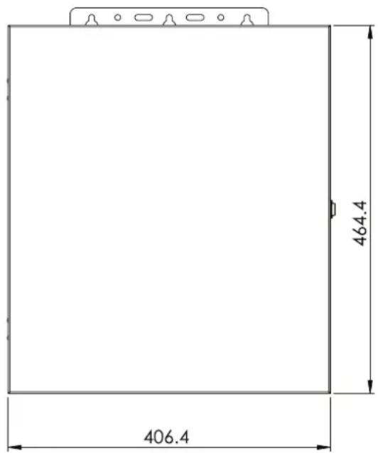
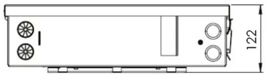
natural_image
Technical line drawing of a rectangular device with circular components and a dimension label (122), no readable text or symbols beyond the dimension marker.2.4 Basic Plumbing
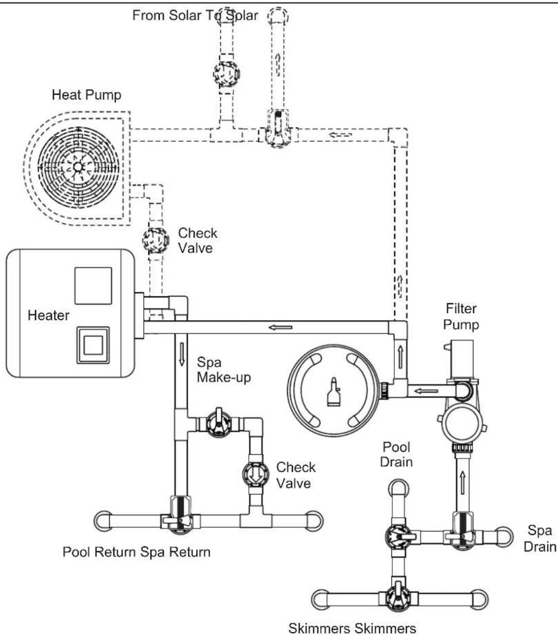
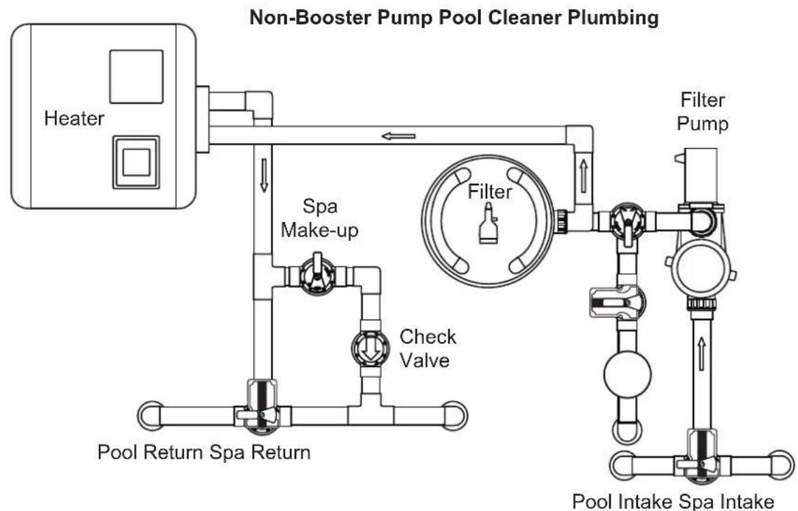
2.4.1 Plumbing for Pool and Spa Combination
The following plumbing diagrams illustrate simplified versions of standard plumbing setups for a pool and spa that share the same filter pump, filter, and heater. The intake and return JVAs turn simultaneously so when the spa button is pressed on the AquaLink M8 control panel, water circulation switches between pool and spa (consult the Jandy Pro Series Valve Actuator Installation and Operation Manual to ensure that the JVAs are synchronized and rotate properly). Please consult the Jandy Valve® Plumbing Manual for further examples of pool/spa plumbing.
For pool only/spa only or dual equipment plumbing, please refer to the Jandy Pro Series Valve Plumbing Manual for further examples.
NOTE When the filter system is shared (a pool/spa combo), the spa water must be able to overflow back to the pool.
flowchart
graph TD
    A["Heater"] --> B["Heat Pump"]
    B --> C["Check Valve"]
    C --> D["Pool Return Spa Return"]
    D --> E["Pool Drain"]
    E --> F["Filter Pump"]
    F --> G["Skimmers Skimmers"]
    G --> H["Spa Drain"]
    H --> I["Check Valve"]
    I --> J["Spa Make-up"]
    J --> K["From Solar To Solar"]
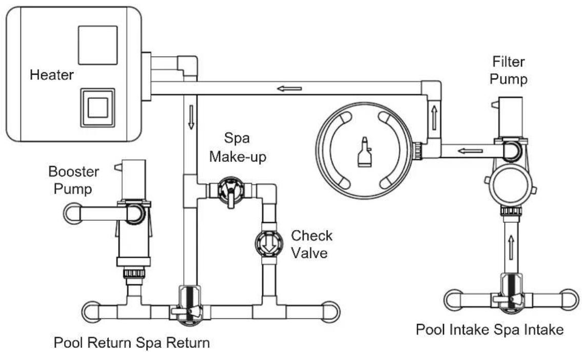
2.4.2 Booster Pump Pool Cleaner Plumbing
flowchart
graph TD
    A["Heater"] --> B["Booster Pump"]
    B --> C["Pool Return Spa Return"]
    C --> D["Check Valve"]
    D --> E["Spa Make-up"]
    E --> F["Filter Pump"]
    F --> G["Pool Intake Spa Intake"]
    style A fill:#f9f,stroke:#333
    style G fill:#bbf,stroke:#333
flowchart
graph TD
    A["Heater"] --> B["Non-Booster Pump Cleaner Plumbing"]
    B --> C["Filter Pump"]
    C --> D["Pool Return Spa Return"]
    D --> E["Check Valve"]
    E --> F["Spa Make-up"]
    F --> G["Water Splitter"]
    G --> H["Filter"]
2.4.3 Basic Plumbing for Dual System
Refer to Figure 1 when plumbing two (2) separate sets of equipment. The basic setup consists of one (1) pump, filter and heater for the pool and another set for the spa.
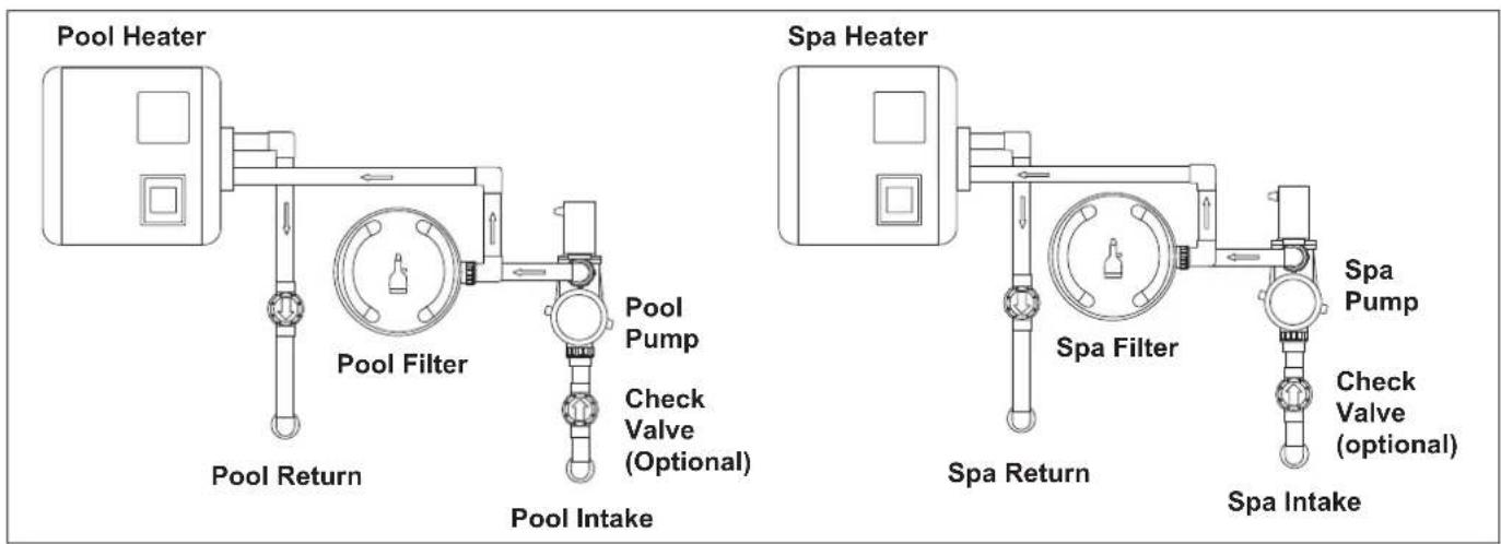
Figure 4. Basic Plumbing for Dual Equipment
2.4.4 Plumbing - Sharing One (1) Heater
When the system setup is using only one (1) heater, plumb the equipment as shown in Figure 5.
Please note that for this type of plumbing a new bezel decal must be applied over the existing decal in order to identify the correct labeling for the HEATER and VALVE buttons.
NOTE When connecting to the AquaLink RS, plug the JVAs into the Intake, Return and Cleaner JVA sockets. Slide DIP Switch S1-6 to the ON position. See wiring diagram in Section 3, Figure 9.
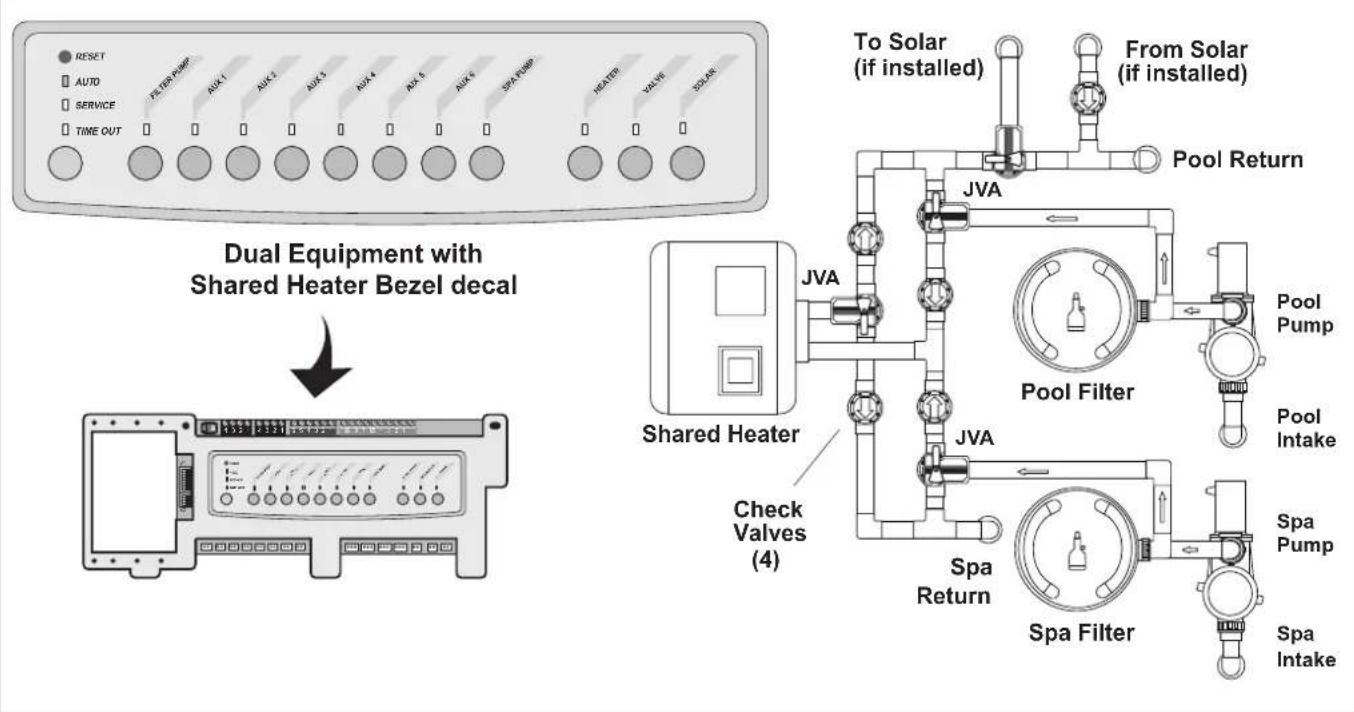
Figure 5. Dual Equipment System with One (1) Heater
Section 3. Installation
3.1 Power Center Mounting
-
The power center should be located at or near the equipment pad. Locate the power center at least 3.5M or more away from pool/spa and 1.5M off the ground. All national, state, and local codes are applicable.
-
Use the mounting brackets and instructions provided with the standard power center.
NOTE The power center is not to be considered as suitable for use as service equipment. Therefore, it is required to have the appropriate means of disconnection, circuit isolation, and/or branch circuit protection installed upstream of the power center.
WARNING
Potentially high voltages in the AquaLink Power Center can create dangerous electrical hazards, possibly causing death, serious injury or property damage. Turn off power at the main circuit of the AquaLink Power Center to disconnect the Power Center from the system. To properly and safely wire the system, be sure to carefully follow the applicable requirements of the latest, enforced version of AS/NZS 3000 and any other applicable local installation codes. All applicable local installation codes must also be adhered to.
3.2 High Voltage Wiring
3.2.1 System Power
Depending on the amount of equipment being controlled, run 1/2" or 3/4" conduit from the power supply panel to the bottom of the power center. Pull in appropriate wire for equipment.
3.2.2 Bonding the Power Center
Install a bonding lug to the power center enclosure. Connect the bond lug, using a #8 solid copper core wire, to an approved earth ground (an approved ground stake, grid, or conducting metal water pipe buried to a sufficient depth). See Figure 6.
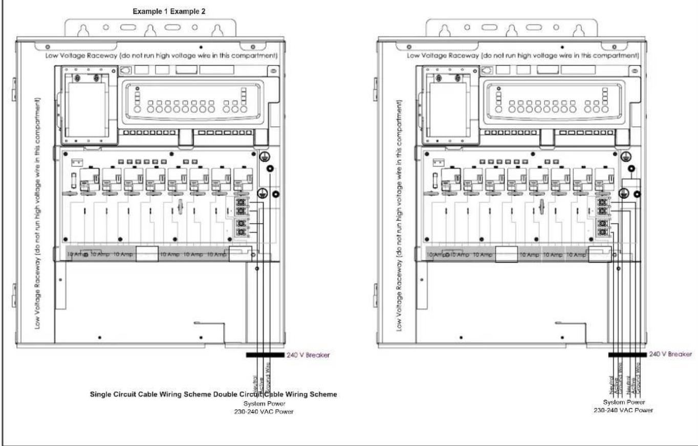
Figure 6. Standard Power Center - Bonding
3.2.3 Variable Speed Pump to Power Center PCB Cable
The low voltage wiring for the variable speed pumps consists of the RS485 communications four conductor, 22 AWG or larger cable. Make provision for the cable to be run between the pump and the power center. Never run high voltage and low voltage in the same conduit. Pull cable through the knockout with the Heyco fitting and into the low voltage compartment. Strip back jacket 150mm. Strip each wire 6mm and connect to the red, 4-pin connector on the power center PCB. A multiplex kit may be required if there are more than two cables running to each of the red, 4-pin connectors on the power center PCB. See Figure 7.
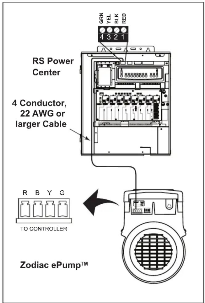
Figure 7. Low Voltage Wiring for Zodiac ePump
3.2.4 Wiring the Pentair ^® Pump
The Pentair IntelliFlo ^® VF LCD control panel is disabled when communicating with the AquaLink system and "DISPLAY NOT ACTIVE" will be displayed. Note that AquaLink M8 will not start communicating with the Pentair IntelliFlo VF until it has been configured accordingly. See the AquaLink Owner's Manual for more information.
Connection from the AquaLink power center PCB to the Pentair variable speed/flow pumps is via the two-wire cable. The cable pin out is shown in Figure 8.
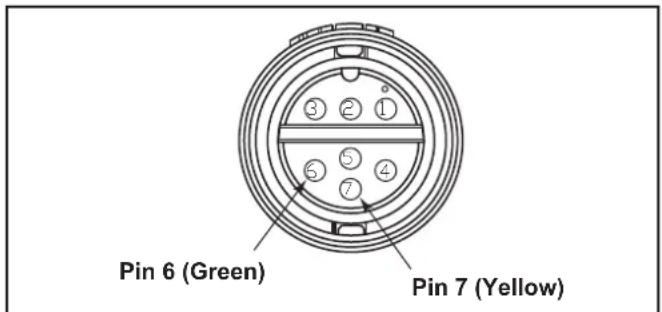
Figure 8. Cable Connector at the Pump Side
| Jandy® RS485 (RED) Connector | Pentair RS485 Cable Assembly |
| Pin 1 (no connection) | |
| Pin 2 Yellow Wire | |
| Pin 3 Green Wire | |
| Pin 4 (no connection) |
3.2.5 Wiring the Zodiac ^® ePump
Connection from the AquaLink power center PCB to the Zodiac ePump is via an RS485 cable. The cable pin out is shown below.
| RS485 Wire Connections for Zodiac ePump | |
| This side connects to J1 or J4 of power center PCB or to the multiplexer PCB. | This side of the cable connects to the Zodiac ePump. |
| Pin 1(no connection, not used) | Pin 1(no connection, not used) |
| Pin 2 (SD+) Pin 2 (SD+) | |
| Pin 3 (SD-) Pin 3 (SD-) | |
| Pin 4(no connection, not used) | Pin 4(no connection, not used) |
3.2.6 Zodiac ePump DIP switch settings
As shown in Figure 13, the 4-position dip switch is located at the rear of the Zodiac ePump. This dip switch serves two functions - it determines what type of control will be used with the pump and it selects the pump address.
The SW 1 (switch 1) and SW 2 are turned ON if the pump is to be controlled by a stand alone controller or OFF if the pump is to be controlled by the AquaLink.
| SW 1 SW 2 | CONTROL | |
| OFF OFF | AquaLink | |
| ON OFF | ||
| OFF ON | ||
| ON ON Stand Alone | ||
The SW 3 and SW 4 are turned ON/OFF to select the pump address.
| SW 4 SW 3 | PUMP No. | |
| OFF OFF 1 | ||
| OFF ON 2 | ||
| ON OFF 3 | ||
| ON ON 4 |
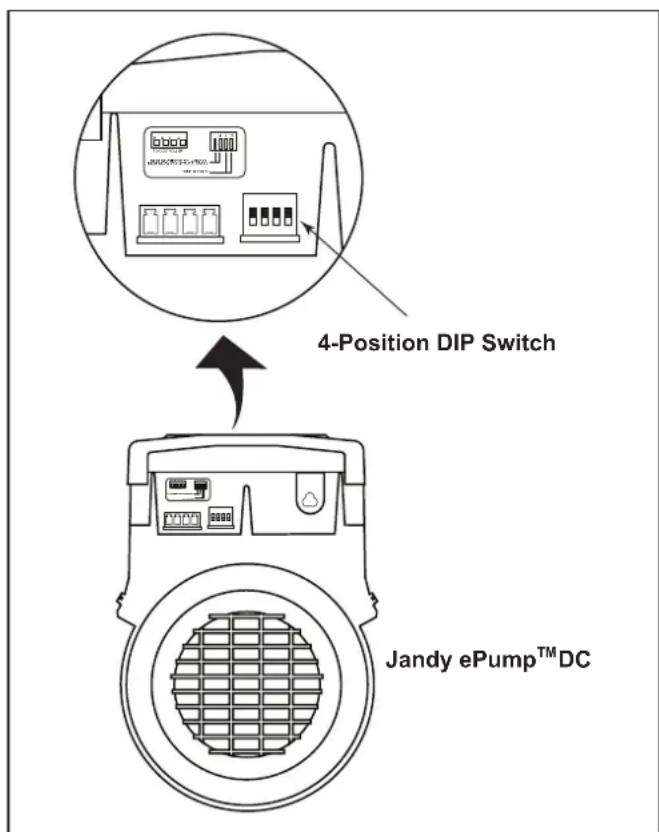
Figure 9. Zodiac ^ ePump ^TM and VS Pump Dip Switch
3.3 Heater Connection
The heater connection section applies to all heaters or heat pumps with thermostatic circuitry of 24 VAC or less.
NOTE If you are connecting a heater with thermostatic circuitry of 120 VAC or greater, do not connect to the green, 10-pin terminal bar. Instead connect the heater to a high voltage relay in the power center and plug the spare relay into the electric heater relay socket on the power center PCB.
3.3.1 Other Brands Heater and Pump Connections
To set up heater connections on heaters and heat pumps made by other manufactures, please refer to the Installation Manual provided with these heaters and heat pumps.
3.4 Temperature Sensors
- Drill hole in pipe between filter pump and filter and install the water temperature sensor per instructions (make certain the o-ring is in place).
- Install air temperature sensor outside the power center can, not in direct sunlight and away from motors and other heat sources.
- Install solar temperature sensor (optional) adjacent to solar panels.
NOTE If a solar sensor is not installed, the solar button can be labeled and used as an extra auxiliary.
- Run the wire to the power center, through the low voltage raceway. Cut off excess wire. Strip the wire jacket back 15cm, then strip each wire 6mm. Connect sensor wires to the green, 10-pin terminal bar (see Figure 10).
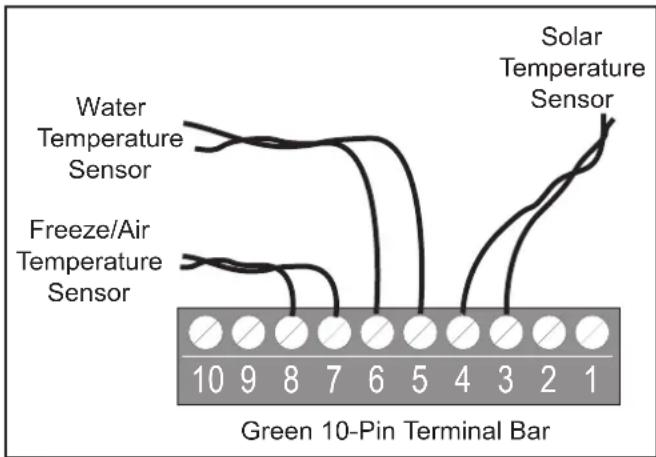
Figure 10. Temperature Sensor Wiring for a Pool/Spa Combination
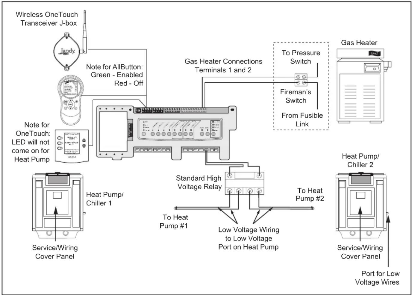
flowchart
graph TD
    A["Wireless OneTouch Transceiver J-box"] --> B["Note for AllButton: Green - Enabled Red - Off"]
    B --> C["Gas Heater Connections Terminals 1 and 2"]
    C --> D["To Pressure Switch"]
    C --> E["Fireman's Switch"]
    C --> F["From Fusible Link"]
    G["Service/Wiring Cover Panel"] --> H["Heat Pump/Chiller 1"]
    H --> I["Standard High Voltage Relay"]
    I --> J["To Heat Pump #1"]
    I --> K["Low Voltage Wiring to Low Voltage Port on Heat Pump"]
    L["Service/Wiring Cover Panel"] --> M["Heat Pump/Chiller 2"]
    M --> N["To Heat Pump #2"]
    O["Service/Wiring Cover Panel"] --> P["Port for Low Voltage Wires"]
Figure 11. Heater and Heat Pump/Chiller Wiring
3.5 Jandy ^® Pro Series Valve Actuators
JVA cable is type SJW-A marked water resistant class 3 cable and does not require conduit. Knockouts and Heyco ^® fittings are provided in the low voltage raceway.
- Route the JVA wire to the power center.
- Run the wire through the low voltage raceway and plug the JVA connectors into their proper sockets (see Section 6. Power Center Wiring Diagram). Verify that the JVA on the suction plumbing is connected to the Intake JVA Socket, and the discharge plumbing is connected to the Return JVA Socket.
NOTE Do not coil the JVA wires inside power center. To shorten the wire, remove the JVA cover and disconnect the wire. Shorten, strip, and reconnect.
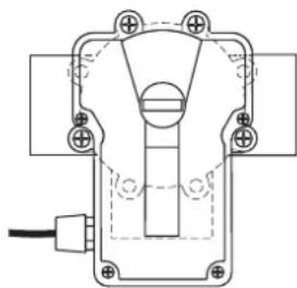
- For alternate plumbing configurations the JVA cam settings can be adjusted as needed. See the Jandy Pro Series Valve Actuator Installation and Operation Manual, Cam Setting Chart for proper settings.
3.5.1 JVA Mounting Positions
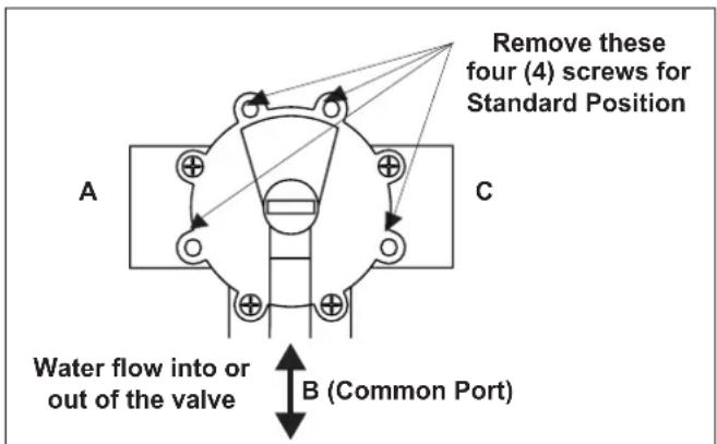
Figure 12. Standard Plumbing
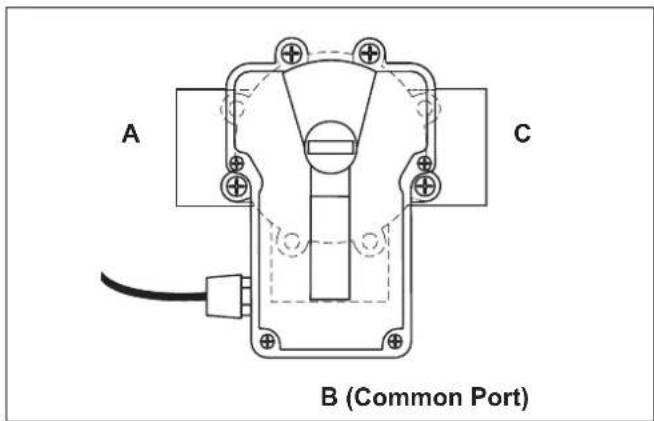
Figure 13. Standard JVA Mounting
3.5.2 Actuator Mounting
NOTE: If valves are plumbed and mounted in standard positions, there is no need to adjust the actuator cams.
JVAs may be mounted onto valves in any of the four (4) positions shown below.
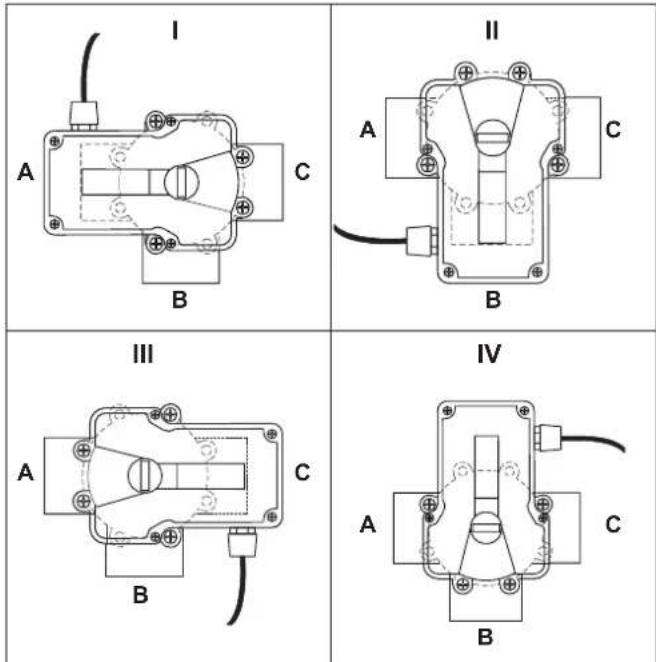
Figure 14. JVA Mounting Positions
- Unscrew the locking knob by turning the knob counterclockwise. Remove the locking knob and valve handle (see Figure 15).
- For standard valves, remove the four (4) large Phillips head screws from the valve. The location of the screws you remove will determine how the actuator will be mounted (see Figure 15). When installing the large 3" valve, it is not necessary to remove any screws.
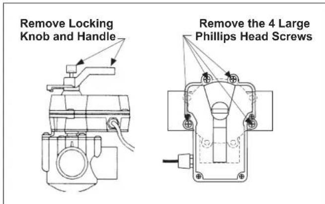
Figure 15. Remove Locking Knob and Lid Screws
- Turn the actuator over to see into the actuator shaft. There are four (4) "teeth" inside of the shaft. Align with the smallest slot on the valve (see Figure 5).
- Place the actuator onto the valve.
- Rotate the actuator while keeping the two shafts engaged until the screw holes on the actuator legs align with the empty screw holes (from step 2) in the valve (see Figure 6).
- Use the four (4) large 2" Phillips head screws (included) to secure the JVA to the valve.
- Put the valve handle on the actuator shaft. Put the knob on the shaft and tighten (finger tighten only).
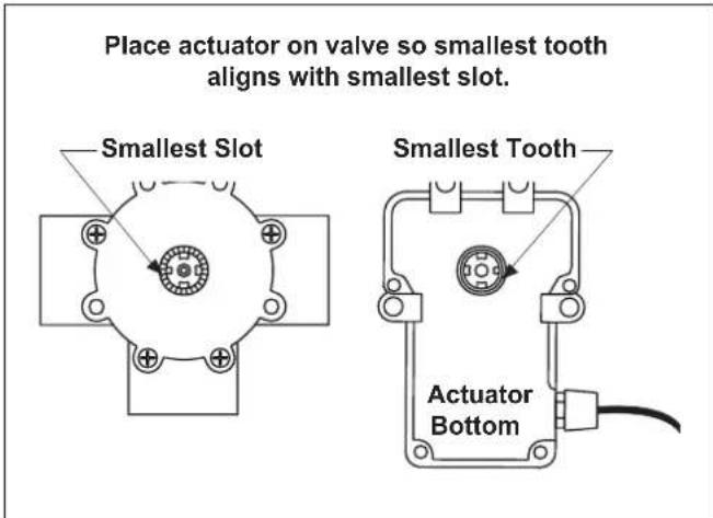
Figure 16. Actuator Mounting
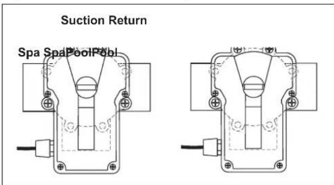
Figure 17. JVA Synchronization, Example
3.5.3 Synchronization JVAs
If the valve is plumbed in the Standard Plumbing position and the actuator is mounted in Standard Mounting position,
you do not have to change the cam settings from the factory settings. However, you may have to synchronize the cams. If the actuator is out of synchronization.
- the actuator will rotate in the wrong direction in relation to its controller (as in a solar heating system)
- one actuator will rotate incorrectly in relation to another actuator (as in pool/spa combination)
Suction Return
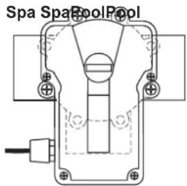
natural_image
Pure mechanical component diagram without any text, numbers, or symbolsFigure 18. JVA Synchronization, Example
For a pool/spa combination, synchronize the valve and the actuator before activation (see Figure 18).
To synchronize the valve and the actuator:
-
Flip the toggle switch located on the bottom of the actuator to the ON 2 position (see Figure 19). The toggle positions are marked on the actuator cover.
-
Retry the system.

ON 1
OFF
ON 2
On/Off switch is located on the bottom of the JVA
Figure 19. JVA Synchronization, Toggle
3.5.4 Resetting the Cams

WARNING
Improper cam settings can result in dead heading of the water flow which can cause injury or property damage. Improper cam settings and/or operation will void the warranty.
NOTE: Before resetting cams, if the valve is plumbed in Standard Plumbing position and the actuator is in Standard Mounting position (see Figure 3). There is no need for resetting the cams. If a port other than "B" is plumbed as the common port or if the actuator is mounted other than Standard Mounting, the cam setting must be changed so the actuator shaft and the valve diverter rotate properly. Refer to the Cam Setting Chart for proper settings.
- Turn OFF actuator power. Unscrew the locking knob by turning the knob counterclockwise. Remove the locking knob and valve handle.
-
Remove the four (4) Phillips head screws that secure the actuator lid and then remove the lid.
-
Rotate the actuator shaft so the arrow mark on the top cam aligns with the microswitch actuator (bottom cam arrow mark should also align with the bottom microswitch actuator, see Figure 20).
Final minor adjustments may be necessary
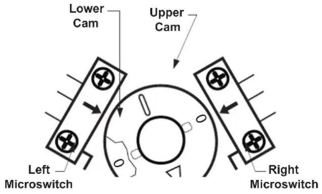
Figure 20. JVA Cams
- Determine the mounting position for the actuator (as per Figure 3, the mounting position will be either I, II, III, or IV). Next, determine what valve port is the common or inlet port (per Figure 3, the common port will be either A, B, or C). Refer to the Cam Setting Chart to determine what the cam settings should be.
- For example, if the actuator is in JVA mounting position "I", and the common port on the valve is port "A", the cam settings would be 90° for the top cam and 180° for the bottom.
NOTE: The cam is marked with the arrow at "0", a long hash mark at the 180° position, and 2 short hash marks at the 90° and 270° positions.
- To set the cams, rotate the cam(s) until the arrow mark on the cam(s) align with the microswitch actuator (see Figure 21).
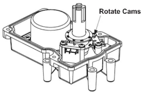
Figure 21. JVA Cam Adjustment
NOTE: The upper cam stops counterclockwise rotation and the lower cam stops clockwise rotation.
- Turn power ON to the actuator and use the toggle switch located on the bottom of the actuator to check rotation.
- Move the toggle switch to either ON 1 or ON 2. Allow the actuator shaft to move until it stops.
- Check valve diverter position*, if the position is correct flip the toggle switch in the opposite direction and allow
Cam Setting Chart
NOTE: Before resetting cams, always rotate the actuator shaft so the arrow aligns with the pointer above its microswitch.
| Actuator Mounting | Water Enters Port Common Port | Cam Setting | Water Exits Valve | |||
| Top Cam | Bottom Cam | Port | or | Port | ||
| *IA 90 180 B C | ||||||
| IB | 90 270 | A C | ||||
| I | C | 180 90 | A B | |||
| *II | A | 180 90 | B C | |||
| II | B | 0 | 0 | A C | ||
| II C 90 180 | A B | |||||
| *III | A 90 180 B C | |||||
| III | B | 270 90 | A C | |||
| III | C | 0 | 270 | A | B | |
| *IV | A | 0 | 270 B C | |||
| IV | B | 180 | 180 | A | C | |
| IV | C | 270 | 0 | A | B | |
*Two Port Valve Settings
the shaft to stop again. If the stop positions are not correct, reset the cams until correct.
NOTE: If the actuator does not move in either direction, refer to Section 6, Troubleshooting.
10. Replace the lid and tighten screws. Replace the handle and locking knob.
NOTE: The end of the handle which has the word OFF embossed on it exactly duplicates the shape of the valve diverter. When the handle is placed on a valve or actuator shaft the word OFF will be directly over the center of the valve diverter.
3.6 OneTouch™ Control Panel Installation
3.6.1 Surface Mount OneTouch Installation
- With the aid of the homeowner, find the best location for the control panel.
- Place surface mount box in the location chosen for the control panel. Mark the holes for drilling. Drill 5mm holes for the sheet rock anchors and a 45mm hole for the 4-conductor cable.
- Run the 4-conductor cable from the power center to the location of the control panel (see Figure 10).
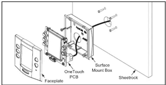
Figure 22. OneTouch™ Surface Mount Installation
- Pull the 4-conductor cable through the hole in the wall and the hole in the surface mount box. Mount the box to the wall using the screws provided.
- Wire the 4-conductor cable to the red, 4-pin terminal bar (see Figure 23). Push the 4-pin terminal bar onto the back of the OneTouch PCB. Place the PCB with LCD and buttons back into the box. Insert the screws and hand tighten. Do not overtighten. Snap the faceplate into place.
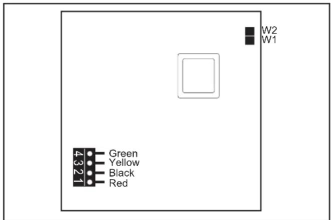
Figure 23. OneTouch PCB - Back View
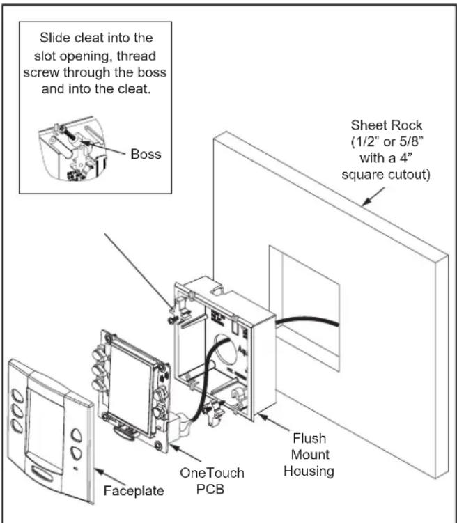
Figure 24. OneTouch Flush Mount Installation
3.6.2 Flush Mount OneTouch Installation
- With the aid of the homeowner, find the best location for the control panel.
- Place the flush mount box in the location chosen for the control panel. Level the box and trace around the outside of the box with a pencil. Cut the hole being careful not to oversize.
- Route the 4-conductor cable from the power center to the indoor control panel.
- Pull the 4-conductor cable through the hole in the wall and the hole in the flush mount box. Push the flush mount box into the hole in the wall with the correct orientation (see Figure 24).
- Depending on what size sheet rock (16mm or 13mm), determine which side of the cleat is to be facing you (see Figure 25).
- Insert a screw through the screw boss (see Figure 28). Put a cleat into the top "U" shaped hole. Hand tighten the screw and repeat the process for the bottom cleat.
- Wire the 4-conductor cable to the red, 4-pin terminal bar. Push the 4-pin terminal bar onto the back of the OneTouch PCB. Place the OneTouch PCB back into the Flush Mount Housing. Insert the screws with rubber washers and hand tighten. Do not overtighten. Snap the faceplate into place.
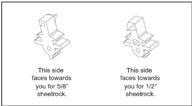
Figure 25. Cleat Orientation
3.6.3 Multiple AquaLink M8 OneTouch Control Panel Installation
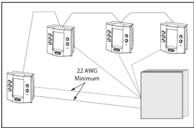
The AquaLink M8 allows each system to support a maximum of 4 indoor control panels (see Figure 14). The control panels may be wired “in series” starting from the first control panel (solid lines), or wired “in parallel” from the AquaLink M8 power center (dotted lines), or any combination of the two. In other words, any number of indoor control panels and/or power centers can be connected by means of the red, 4-pin terminal bar in any combination of “series” or “parallel” wiring.
NOTE Minimum wire size should be 22 AWG. If more than one control panel is installed, or the length of run is more than 100M, larger wire should be used.
flowchart
graph TD
    A["Device 1"] --> B["Device 2"]
    C["Device 3"] --> D["Device 4"]
    E["Device 5"] --> F["Device 6"]
    G["Device 7"] --> H["Device 8"]
    I["Device 9"] --> J["Device 10"]
    K["Device 11"] --> L["Device 12"]
    M["Device 13"] --> N["Device 14"]
    O["Device 15"] --> P["Device 16"]
    Q["Device 17"] --> R["Device 18"]
    S["Device 19"] --> T["Device 20"]
    U["Device 21"] --> V["Device 22"]
    W["Device 23"] --> X["Device 24"]
    Y["Device 25"] --> Z["Device 26"]
    AA["Device 27"] --> AB["Device 28"]
    AC["Device 29"] --> AD["Device 30"]
    AE["Device 31"] --> AF["Device 32"]
    AG["Device 33"] --> AH["Device 34"]
    AI["Device 35"] --> AJ["Device 36"]
    AK["Device 37"] --> AL["Device 38"]
    AM["Device 39"] --> AN["Device 40"]
    AO["Device 41"] --> AP["Device 42"]
    AQ["Device 43"] --> AR["Device 44"]
    AS["Device 45"] --> AT["Device 46"]
    AU["Device 47"] --> AV["Device 48"]
    AW["Device 49"] --> AX["Device 50"]
    AY["22 AWG Minimum"] --> AZ["Device 10"]
Figure 26. Installing Multiple OneTouch Control Panels
3.6.4 AquaLink M8 OneTouch™ Control Panel Jumper Settings
Move these jumpers only when installing more than one control panel on a system (see Figure 27). The jumpers are used to give each control panel a unique system address. When replacing an existing control panel, change the jumper settings to match those on the one being replaced.
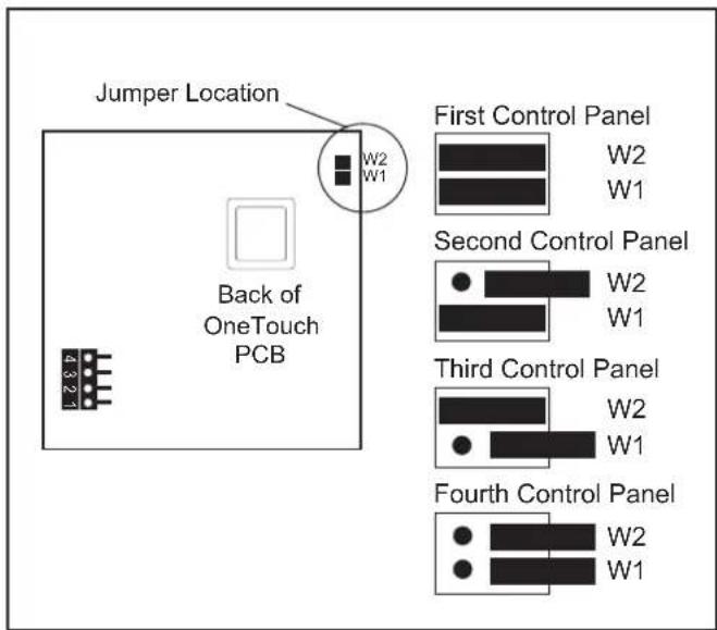
Figure 27. Jumper Settings for Multiple OneTouch™ Control Panels
Section 4. System Startup
4.1 OneTouch Programming
4.1.1 Basic Programming
To set a particular piece of equipment to turn on and off at predetermined times, highlight MENU/HELP and press SELECT (see Figure 28). Highlight PROGRAM and press SELECT. Use the UP or DOWN buttons to highlight the equipment (for example, filter pump) then press SELECT. Follow the on-screen prompts. Use the UP or DOWN buttons to pick each number, starting with ON hours, press SELECT to enter and move on to the next item to change, including picking what day(s) the program will run. If you make a mistake, use the BACK button to return to a number. If the program is already entered, highlight CHANGE PROGRAM and step through to the entry that should be corrected.
A VARIABLE SPEED PUMP can be programmed to run at any one of its eight (8) speeds. Power to the variable speed pump is switched on/off by a relay, so to program the pump you need to set a program time for the relay and for any speeds that you wish to run during the pumps on cycle.
In the example shown below, the variable speed pump is used for pool filtration, so it will be powered from the FILTER PUMP relay. Therefore to program the variable speed pump you must first set a program time for the FILTER PUMP relay, then you need to program the desired pump speeds to turn on/off during the FILTER PUMP cycle. If you do not program any speeds to run during the filtration cycle, then by default the variable speed pump will run at the POOL speed setting during its filtration cycle.
Example:
- The total length of the filtration cycle is to be from 8am to 5pm. So program the FILTER PUMP to turn on at 8am and to turn off at 5pm
- To run the variable speed pump at the SPEED3 setting from 8am to 1pm, highlight and select VSP SPD1 PGM, then highlight and select SPEED3, program it to turn on at 8am and off at 1pm.
- To run the variable speed pump at the SPEED4 setting from 1pm to 5pm, highlight and VSP SPD1 PGM, then highlight and select SPEED4, program it to turn on at 1pm and off at 5pm.
| ON OFF DESCRIPTION | ||
| FILTER PUMP | 8AM 5PM | M Total duration of filtration cycle |
| SPEED3 8AM | 1PM | Pump runs at the SPEED3 setting |
| SPEED4 1PM | 5PM | Pump runs at the SPEED4 setting |
NOTE The following items can be found either in the MENU/HELP or in a Sub Menu under SYSTEM SETUP.
4.1.2 Set the Time Menu
MENU/HELP > SET TIME
To set the time, highlight the MENU/HELP and press SELECT. Highlight SET TIME and press SELECT. Use the UP or DOWN button to set the values. Press SELECT to continue.
4.1.3 Set the Temperature
1. Pool/Spa Combination
MENU/HELP > SET TEMP > POOL or SPA > SET TEMP VALUE
Highlight MENU/HELP and press SELECT. Highlight SET TEMP and press SELECT. Use the UP or DOWN button to highlight either POOL or SPA and press SELECT. Use the UP or DOWN button to increase or decrease the temperature and press SELECT. Use the BACK button to return to the main screen.
2. Pool/Spa Only
MENU/HELP > SET TEMP > TEMP1 > SET TEMP1 VALUE > TEMP2 > SET TEMP2 VALUE
Highlight MENU/HELP and press SELECT. Highlight SET TEMP and press SELECT (TEMP1 must be higher than TEMP2). Press SELECT on TEMP1. Use the UP or DOWN button to increase or decrease the temperature and press SELECT.
Highlight TEMP2 and press SELECT (TEMP1 must be higher than TEMP2). Use the UP or DOWN button to increase or decrease the temperature and press SELECT. Use the BACK button to return to the main screen.
3. Maintain Temperature
MENU/HELP > SET TEMP > MAINTAIN
In the SET TEMP menu, highlighting MAINTAIN and pressing SELECT will turn on (or off) the MAINTAIN function. MAINTAIN will run the pump for the chosen body of water to keep the water at the desired temperature. If this function is on, as long as the heater/chiller is enabled for that body of water, the system will automatically turn on the pump every couple of hours for just enough time to test the water temperature. If the temperature meets the set point, the pump will return to off. If the measured temperature is different than the set temperature, the pump will stay on and the heater/chiller will operate long enough to bring the water to the set temperature.
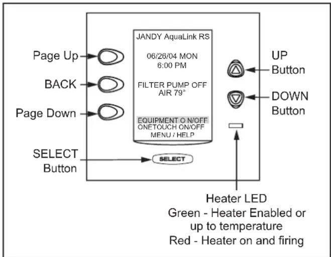
flowchart
graph TD
    A["Page Up"] --> B["JANDY AquaLink RS 06/26/04 MON 6:00 PM"]
    C["BACK"] --> D["FILTER PUMP OFF AIR 79°"]
    E["Page Down"] --> F["EQUIPMENT ON/OFF ONETOUCH ON/OFF MENU / HELP"]
    G["SELECT Button"] --> H["UP Button"]
    I["UP Button"] --> J["DOWN Button"]
    K["Select Button"] --> L["Heater LED Green - Heater Enabled or up to temperature Red - Heater on and firing"]
Figure 28. OneTouch Control Panel Buttons
4. Maintain Temperature Hours
MENU/HELP > SET TEMP >HOURS
Sets the desired time when this function will activate (default setting is 12AM to 12AM; 24 hours a day). Highlight HOURS and press SELECT. Use the UP or DOWN buttons to change the HOURS the system will maintain the set temperature.
4.1.4 Label Auxiliary Functions
MENU/HELP > SYSTEM SETUP > LABEL AUX > AUX 1-X > CHOOSE LABEL TYPE > CHOOSE LABEL
Highlight MENU/HELP and press SELECT. Highlight SYSTEM SETUP and press SELECT. Highlight LABEL AUX and press SELECT. Highlight the AUX you want to label and press SELECT. Highlight GENERAL, LIGHT, WATERFALL or CUSTOM LABEL and press SELECT. Choose a name within these categories by using the UP or DOWN button or the PAGE UP or PAGE DOWN button, press SELECT when you find the correct name. Choose CUSTOM to
type in your own names.
NOTE The Auxiliary labels AIR BLOWER and FILL LINE have an automatic 30 minute runtime. To change this setting, refer to the DEVICE RUNTIME feature. If DIP switch S1-1,2 or 3 are on, auxiliaries 1, 2 and 3 are labeled CLEANER, LOW SPEED and SPILLOVER respectively and cannot be relabeled.
4.1.5 Set Freeze Protection
MENU/HELP > SYSTEM SETUP > FREEZE PROTECT > SET TEMP VALUE > SELECT FREEZE PROTECT DEVICE
Highlight MENU/HELP and press SELECT. Highlight SYSTEM SETUP and press SELECT. Highlight FREEZE PROTECT and press SELECT. Use the UP or DOWN button to change the temperature. Once the temperature is set press the SELECT button to move to the next screen to assign freeze protection to a selected piece of equipment. Highlight a device and press SELECT. "X" means the device has been assigned.
NOTE The filter pump is always assigned to freeze protection.
4.1.6 Assign JVs
MENU/HELP > SYSTEM SETUP > ASSIGN JAVAs > SELECT JVA
Highlight MENU/HELP and press SELECT. Highlight SYSTEM SETUP and press SELECT. Highlight ASSIGN JVA and press SELECT. Highlight the JVA you wish to assign and press SELECT.
NOTE If a solar sensor is installed, the solar JVA will automatically be assigned and will be marked as USED.
4.1.7 Seasonal Adjust
MENU/HELP > SYSTEM SETUP > SEASONAL ADJ > SELECT FILTRATION/SPRINKLERS/FILL LINE/CLEANER
Highlight MENU/HELP and press SELECT. Highlight SYSTEM SETUP and press SELECT. Highlight SEASONAL ADJ and press SELECT. Use the UP/DOWN BUTTON TO choose FILTRATION, SPRINKLERS, FILL LINE, and CLEANER, then press SELECT.
NOTE FILL LINE will be displayed on the screen only if an AUX has been assigned to fill the label. CLEANER will be displayed on the screen only if DIP switch S1-1 is ON. AQUAPURE will be displayed only if a chlorine generator is attached to the system.
4.2 OneTouch™ Reset and Display Messages
4.2.1 Restarting the System
MENU/HELP > SYSTEM SETUP > CLEAR MEMORY > CONTINUE > FINAL WARNING > CONTINUE
To remove all labeling, programming, assignments and temperature settings, highlight MENU/HELP and press SELECT. Highlight SYSTEM SETUP and press SELECT. Highlight CLEAR MEMORY and press SELECT. Highlight CONTINUE and press SELECT. Use the UP or DOWN button to highlight YES or NO and press SELECT. There will be about a 15 second delay before you see the FINISHED screen. Highlight CONTINUE and press SELECT to return to the SYSTEM SETUP.
4.3 Variable Speed Pump Menu
NOTE This equipment may not be part of your system. Please check with your installer.
The VAR SPEED PUMP menu is used to select the variable speed pump type (Jandy® ePump™ DC, Jandy ePump™ AC, Pentair® IntelliFlo® VF, Pentair IntelliFlo VS, or Pentair IntelliPro® VS) and to select the various pump settings. To interface the IntelliPro VS, select IntelliFlo VS.
4.3.1 To select the Pump Type
To select a pump, highlight the desired model and press SELECT. An X will appear next to the selection. To control the IntelliFlo VS, select the IntelliFlo VS.
MENU/HELP > SYSTEM SETUP > VAR SPEED PUMP > SELECT MODEL > SELECT JANDY EPUMP/INTELLIFLOVS/INTFLOVF/INTELLIPRO
In SYSTEM SETUP menu, highlight VAR SPEED PUMP and press SELECT, highlight PUMP MODEL and press SELECT. Use the UP/DOWN arrow keys to highlight the desired pump, then press SELECT.
4.3.2 To set up the Pump Application
The AquaLink can control up to 4 variable speed pumps. In the PUMP SETUP menu the user can select each pump (1-4) and configure how the pump(s) are to be used. For example if the pump is to be used for pool/spa filtration then you would select FILTRATION as the pump application. If the pump is to be used for a water feature then you would select AUX. PUMP as the pump application. The default setting is NOT INSTALLED.
| COMBO POOL | SPAONLY | DUAL EQUIP-MENT |
| FILTRATION FILTRATION POOL PU | MP | |
| AUX. PUMP AUX. PUMP SPA PUMP | ||
| NOT INSTALLED NOT INSTALLED AU | X. PUMP | |
| NOT INSTALLED | ||
If the system is not going to control a variable speed pump then leave the application set to NOT INSTALLED. If the system is going to control a variable speed pump, then you would set the application accordingly. In the example below we are telling the system that it will be controlling one (1) variable speed pump.
MENU/HELP > SYSTEM SETUP > VSP SETTINGS > SELECT PUMP APPLICATION > SELECT PUMP1 > SELECT ITEM
In VSP SETTINGS menu, highlight PUMP APPLICATION and press SELECT, highlight PUMP1 and press SELECT. Use the UP/DOWN arrow keys to highlight the item, then press SELECT. An X will appear next to the selection.
4.3.3 To set SCALE/MIN-MAX Parameters
This screen allows the user to set a global minimum and maximum speed or flow for the indicated pump. The SCALE setting is fixed to RPM for the Jandy ePump and the Pentair IntelliFlo VF. The SCALE setting is fixed to GPM for the Pentair IntelliFlo VF.
MENU/HELP > SYSTEM SETUP > VSP SETTINGS > SELECT MIN-MAX SETTINGS > SELECT PUMP1 > CHOOSE LIMIT
In VSP SETTINGS menu, highlight MIN-MAX SETTINGS and press SELECT, highlight PUMP1 and press SELECT. Use the UP/DOWN arrow keys to highlight the desired LIMIT, then press SELECT.
4.3.4 To set Pump Speed
There are eight (8) default speed presets for each variable speed pump.
MENU/HELP > SYSTEM SETUP > VSP SETTINGS > SELECT SPEED/LABELS > SET SPEEDS> CHOOSE SPEED
In VSP SETTINGS menu, highlight SPEED/LABELS and press SELECT, highlight PUMP1 and press SELECT. Use the UP/DOWN arrow keys to highlight SET SPEED and press SELECT. Use the UP/DOWN arrow keys to highlight the desired item, then press SELECT. Use the UP/DOWN arrow keys to highlight the desired speed preset, then press SELECT. Use the UP/DOWN arrow keys to adjust the speed value, then press SELECT.
NOTE The FREEZE PROTECT speed is also set from this menu.
4.3.5 To re-label the Speed Preset
Each of the eight (8) speed presets has a label and each of those labels can be changed from the default value.
MENU/HELP > SYSTEM SETUP > VSP SETTINGS > SELECT SPEED/LABELS > LABELS SPEEDS> CHOOSE ITEM > SELECT GENERAL LABELS/CUSTOM LABELS
In the SPEED SETTINGS menu, highlight LABEL SPEEDS and press SELECT. Use the UP/DOWN
arrow keys to highlight the desired PUMP, then press SELECT. Use the UP/DOWN arrow keys to highlight either GENERAL LABELS or CUSTOM LABELS and then press SELECT.
4.3.6 Default Preset Speed Labels (RS Combo and RS only)
When a pump is configured for FILTRATION, the speed presets will be labeled as shown in the table below. The presets can be relabeled.
| Default Labels when Pump is configured for FILTRATION | |||
| PRESET # | POOL/SPA COMBO | POOL/SPA ONLY | SPEED (RPM) |
| 1 POOL | POOL 1725 | ||
| 2 SPA | SPEED2 2750 | ||
| 3 SPEED3 or CLEANER (if dip S1-1 is on) | SPEED3 or CLEANER (if dip S1-1 is on) | 2750 | |
| 4 SPEED4 or SPILLOVER (if dip S1-3 is on) | SPEED4 2750 | ||
| 5 POOL | HEAT TEMP1 | 2250 | |
| 6 | SPA HEAT | TEMP2 2250 | |
| 7 SOLAR | HEAT (if dip S1-7 is on) or HEAT-PUMP (if dip S1-7 is on) or SPEED7 | SOLAR HEAT (if dip S1-7 is on) or HEAT-PUMP (if dip S1-7 is on) or SPEED7 | 2750 |
| 8 | INFLOOR | INFLOOR | 2750 |
4.3.7 Preset 1:
The default label for preset #1 is POOL. This label is tied to the pool filtration mode. Anytime the pool pump is supposed to turn on, this preset is selected.
4.3.8 Preset 2:
On combo systems the default label for preset #2 is SPA. This label is tied to the spa filtration mode, anytime the spa pump is supposed to turn on, this preset is selected.
4.3.9 Preset 3:
On combo systems, if dip switch S1-1 is ON, then the default label for this preset is CLEANER. Anytime the cleaner mode is turned on the pump will run at the speed setting of this preset.
On a combo system, if dip switch S1-1 is OFF, then the default label for this preset is SPEED3.
4.3.10 Preset 4:
If dip switch S1-3 is ON, then the default label for this preset is SPILLOVER. Anytime the spillover mode is turned on the pump will run at the speed setting of this preset.
If dip switch S1-3 is OFF, then the default label for this preset is SPEED4.
4.3.11 Preset 5:
On pool/spa combo systems the default label is POOL HEAT. When the pool heater is enabled the pump will run at this speed.
On pool/spa only systems the default label is TEMP1. When the pump is running and the heater set point TEMP1 is enabled, then the pump will run at this preset.
4.3.12 Preset 6:
On pool/spa combo systems the default label is SPA HEAT. When the system is in the SPA mode and the SPA HEATER is enabled then the pump will run at this speed.
| RECOMMENDED SETTINGS FOR THE SYSTEM ID DIP SWITCHES | |||||||
| Communication Channel | DIP SW 1 (Weight 1) | DIP SW 2 (Weight 2) | DIP SW 3 (Weight 4) | DIP SW 4 (Weight 8) | DIP SW 5 (Weight 16) | DIP SW 6 (Weight 32) | DIP SW 7 (Weight 64) |
| 0 | OFF | OFF | OFF | OFF | OFF | OFF | OFF |
| 1 | ON | OFF | OFF | OFF | OFF | OFF | OFF |
| 2 | OFF | ON | OFF | OFF | OFF | OFF | OFF |
| 3 | ON | ON | OFF | OFF | OFF | OFF | OFF |
| 4 | OFF | OFF | ON | OFF | OFF | OFF | OFF |
| 5 | ON | OFF | ON | OFF | OFF | OFF | OFF |
| 6 | OFF | ON | ON | OFF | OFF | OFF | OFF |
| 7 | ON | ON | ON | OFF | OFF | OFF | OFF |
| 8 | OFF | OFF | OFF | ON | OFF | OFF | OFF |
| 9 | ON | OFF | OFF | ON | OFF | OFF | OFF |
On pool/spa only systems the default label is TEMP2. When the pump is running and the heater set point TEMP2 is enabled, then the pump will run at this preset.
4.3.13 Preset 7:
If the system is in the SOLAR HEAT mode or the HEAT PUMP mode then the pump will run at this preset speed. If the system is not configured for solar heat or a heat pump then the default label will be SPEED7.
4.3.14 Preset 8:
When the In-Floor clean mode is enabled and the pump is running, it will be running at this preset speed.
4.5.7 Default Preset Speed Labels (Dual Equipment)
When a pump is configured to be either a POOL PUMP or a SPA PUMP, the speed presets will be labeled as shown in the table below. The presets can be relabeled but the operation of the speeds may be changed by doing so.
| Default Labels and Speeds when Pumps are configured as POOL PUMP and SPA PUMP (Dual Equipment Systems) | |||
| PRESET # | POOL PUMP SPA PUMP | SPEED | |
| 1 POOL SPEED1 1725 | |||
| 2 SPEED2 SPA 2750 | |||
| 3 SPEED3 or CLEANER(if dip S1-1 is on) | SPEED3 2750 | ||
| 4 SPEED4 SPEED4 2750 | |||
| 5 POOL HEAT SPEED5 2250 | |||
| 6 SPA HEAT SPA HEAT 2250 | |||
| 7 SOLAR HEAT(if dip S1-7 is on)or HEATPUMP(if dip S2-7 is on)or SPEED7 | SPEED7 2750 | ||
| 8 INFLOOR SPEED8 2750 | |||
4.3.15 Preset 1:
On a dual equipment system when a pump is configured as a POOL PUMP, the default label for preset #1 is POOL. This label is tied to the pool filtration mode. Anytime the pool pump is supposed to turn on, this preset is selected.
On a dual equipment system when a pump is configured as a SPA PUMP, the default label for preset #1 is SPEED1.
4.3.16 Preset 2:
On a dual equipment system when a pump is configured as a SPA PUMP, the default label for preset #2 is SPA. This label is tied to the spa filtration mode. Anytime the spa pump is supposed to turn on, this preset is selected.e.
On a dual equipment system when a pump is configured as a POOL PUMP, the default label for preset #2 is SPEED2.
4.3.17 Preset 3:
For the pool pump, if dip switch S1-1 is ON, then the default label for this preset is CLEANER. Anytime the cleaner mode is turned on the pump will run at the speed setting of this preset. If dip switch S1-1 is OFF, then the default label for this preset is SPEED3.
For the spa pump the default label is SPEED3.
4.3.18 Preset 4:
The default label is SPEED4.
4.3.19 Preset 5:
For the pool pump the default label is POOL HEAT. When the pool heater is enabled the pump will run at this speed.
For the spa pump the default label is SPEED5.
4.3.20 Preset 6:
For the pool pump the default label is SPEED6.
For the spa pump the default label is SPA HEAT. When the spa heater is enabled the pump will run at this speed.
Preset 7:
For the pool pump, if the system is in the SOLAR HEAT mode or the HEAT PUMP mode then the pump will run at this preset speed. If the system is not configured for solar heat or a heat pump then the default label will be SPEED7.
For the spa pump the default label is SPEED7.
4.3.21 Preset 8:
For the pool pump, when the In-Floor clean mode is enabled and the pump is running, it will be running at this preset speed.
For the spa pump the default label is SPEED8.
4.4 OneTouch ^TM System Defaults and General Modes
| Default Temperature (Pool/Spa Combination)Default Pool Temp = 80°FDefault Spa Temp = 102°F |
| Default Temperature (Pool/Spa Only)Default TEMP1 = 80°FDefault TEMP2 = 60°F |
| Default Spa Side Switch SettingsButton 1 = Spa (Filter Pump for pool/spa only models)Button 2 = Spa Heater (Temp1 for pool/spa only models)Button 3 = AUX1Button 4 = AUX2 |
| Default Freeze Protection SettingsFILTER PUMP: freeze protection ON. ALL OTHER EQUIPMENT, freeze protection OFF. |
| NOTE If you select SPA to be freeze protected, water circulation will switch between pool and spa every 30 minutes during freezing conditions once freeze mode is active. |
4.4.1 Power Center Service Switch
AUTO Mode (automatic)
- The control panel has complete control of all functions.
- All programmed settings will operate.
- All safety delays and equipment protection interlocks are operational.
SERVICE Mode
- The power center has complete control of all functions.
- Service mode must be turned on/off at the power center.
- No programmed settings will work.

CAUTION
In service mode, the safety interlocks for equipment protection are overridden.
TIMEOUT Mode
- The power center has complete control for three (3) hours.
- After three (3) hours the system will return to AUTO mode.
- Programmed on/off times will be overridden during the three (3) hours.
- After the three (3) hour “time out”, the system will resume any programmed items that were overridden.
4.4.2 Power Interruption
In the event there is a power interruption, and the AquaLink M8 system is in service or time Out mode, the system will default to auto. In previous firmware versions, the system would default to last mode of operation.
ATTENTION
Special Note to Startup Person: The AquaLink M8 allows two (2) options for operating the pool equipment on the first day of operation:
Option #1 Once all programming of equipment is completed, the AquaLink® RS will automatically review all programs and turn on any equipment which is programmed to be on.
Option #2 To operate the filter pump or cleaner continually for the first day, leave the power center service button in AUTO mode. At the indoor control panel, press the filter pump or cleaner buttons for the equipment you want to run. The equipment that is activated will run continuously, ignoring the first programmed off time, and will turn off at the programmed off time for the next day (only if a program has been entered).
4.5 PDA Installation
4.5.1 AquaLink Transceiver J-box Installation
Installation Considerations. The remote will transmit through walls and around corners. Steel framing, aluminum siding, wrought iron, cyclone fences, leaded glass, and other 900 MHz frequency items may inhibit/prevent communication between the AquaLink Handheld Remote and the transceiver. The system does not require line of sight to communicate. To optimize communication, it may be helpful to try multiple transceiver locations before permanently mounting it to a location that maximizes its range.
- Turn off all power to the Power Center.
- When practical to do so, mount the Outdoor Transceiver J-box at least 6' above the ground and at least 8' from any air blowers that may be in the vicinity.
- The Transceiver J-box antenna must point towards the sky.
-
Open the door to the Power Center and remove the dead panel.
-
Feed the four conductor wire into the Power Center through the low voltage raceway.
- Cut off the excess wire. Strip the jacket back 6" and strip the individual wires approximately 14 ". Connect the four conductor wire to the red terminal bar on the Power Center PCB.
- Install the dead panel to the Power Center and restore all power.
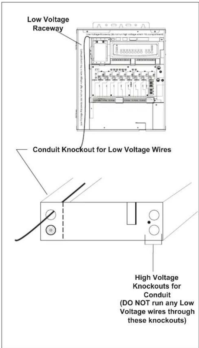
Figure 29. AquaLink J-Box Cable Connection to Power Center PCB
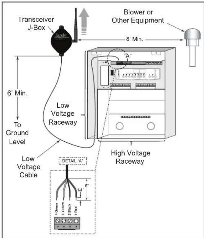
Figure 30. Outdoor Transceiver J-box Installation
4.5.2 AquaLink Handheld Remote Installation
- Remove the Handheld Remote from the packaging.
- On the back of the Handheld Remote, loosen and remove the two (2) screws that secure the cover for the battery chamber (see Figure 31).
- Install two (2) AA batteries. Ensure that the polarity is correct.
- Re-install the cover for the battery chamber and secure with the two (2) screws removed in Step 2.
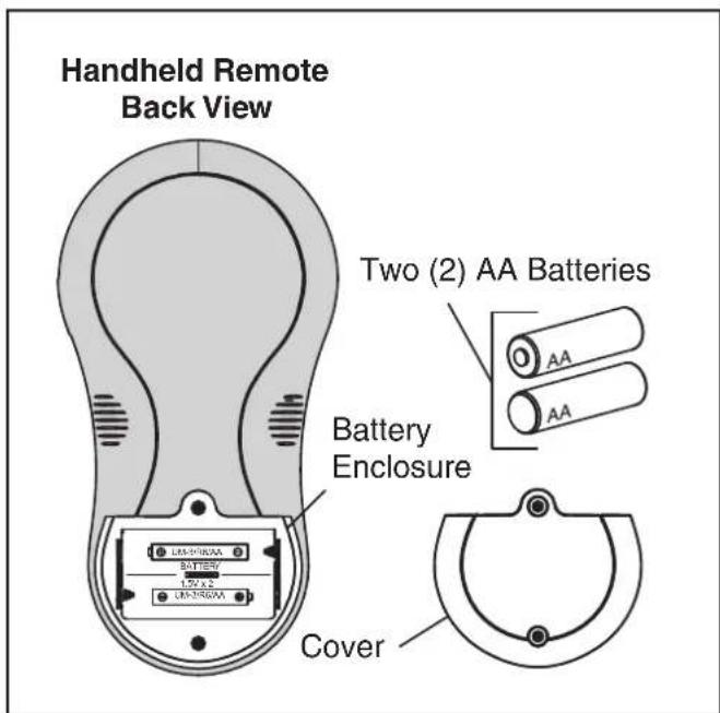
Figure 31. Battery Installation on Handheld Remote
4.5.3 Changing the Frequency Channel
If your AquaLink RS system is turning items on or off at undesignated times, another AquaLink RS Handheld Remote system may be in close proximity using the same or similar frequency channel. To prevent unwanted operation the channel for your AquaLink RS system can be changed. The AquaLink Handheld Remote and the AquaLink Transceiver J-box must be set to the same RF channel.
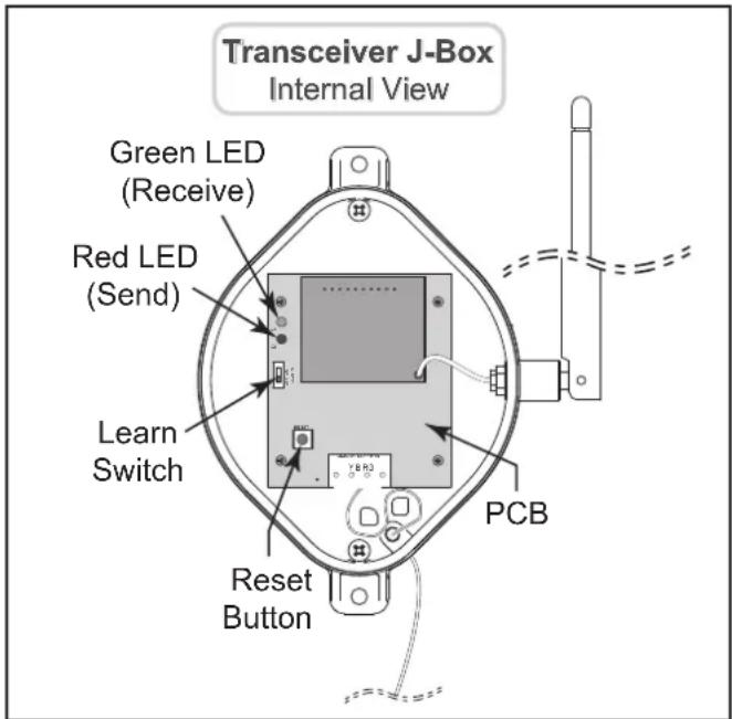
Figure 32. AquaLink Transceiver J-Box - Internal View
- At the Transceiver J-box, remove the cover to expose the PCB (see Figure 20).
- On the AquaLink Handheld Remote, press and hold both the UP and DOWN arrows simultaneously for three (3) seconds. After 3 seconds, the CHANNEL SETUP screen appears. Select a channel.
- Use the UP and DOWN buttons to highlight the desired RF channel. Then press SELECT.
- When the RF channel is selected, the following message appears on the Handheld Remote display screen: Set slide switch on J-Box PCB to the LEARN MODE.
- At the PCB in the Transceiver J-box, slide the Learn Switch to LEARN (ON). See Figure 32.
- On the Handheld Remote display screen, a prompt will appear with instructions to slide the J-box Learn Switch out of LEARN (OFF) and to press the J-box Reset Switch (see Figure 32).
- At the PCB in the Transceiver J-box, slide the
Learn Switch out of LEARN (ON) and press the Reset Switch. The Red and Green LEDs on the J-box will blink simultaneously (see Figure 21).
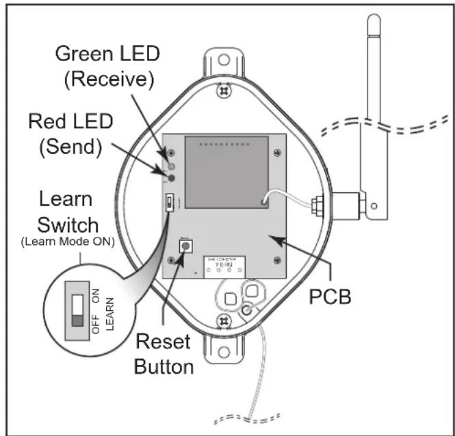
Figure 33. Tranceiver J-box PCB Learn Switch
4.6 PDA Handheld Remote System Defaults and General Modes
4.6.1 Basic Functions
The AquaLink PDA Handheld Remote can turn your pool/spa equipment on and off in any of the following three ways:
- Activate the equipment manually through the EQUIPMENT ON/OFF menu.
- Program the equipment to turn on and off at specific times. See Section 5.3 for a detailed explanation of how to program equipment for automatic operation.
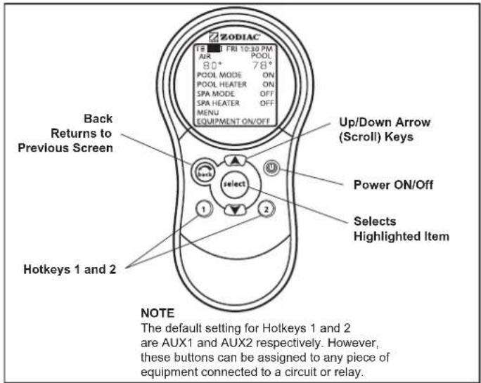
- Use the PDA handheld remote buttons 1 or 2 (Hotkeys). See Section 5.9 for a detailed explanation of how to program Hotkeys 1 and 2.
NOTE The default setting for Hotkeys 1 and 2 are AUX1 and AUX2 respectively. However, these buttons can be assigned to any piece of equipment connected to a circuit or relay.
4.6.2 Using the Buttons
Use the buttons as explained in the diagram below.
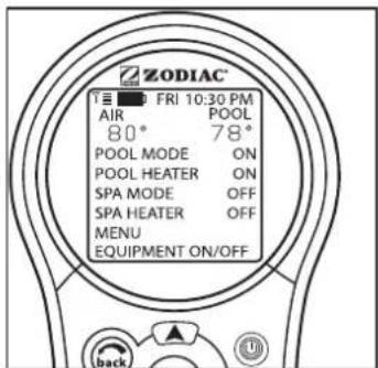
Default screen
4.6.3 Battery Status
The Battery icon is located on the left corner of the display screen, indicates the status of the battery. The PDA Handheld Remote uses two (2) AA batteries. The batteries are located behind the cover on the back side of the Handheld Remote. If the batteries have full or sufficient charge, the icon will appear on the display screen as if the batteries need to be replaced, the icon will consistently blink and appear as
4.6.4 Signal Strength
The Signal Strength icon located on the left corner of the display screen, indicates the signal strength available from the Transceiver J-box to the PDA Handheld Remote. Signal strength is affected (lowered) as the PDA Handheld Remote is moved farther away from the Transceiver J-Box. Also, obstructions, such as walls, can lower the signal strength if located between the PDA Handheld Remote and the Transceiver J-Box.
4.7 PDA Handheld Remote On/Off Menu
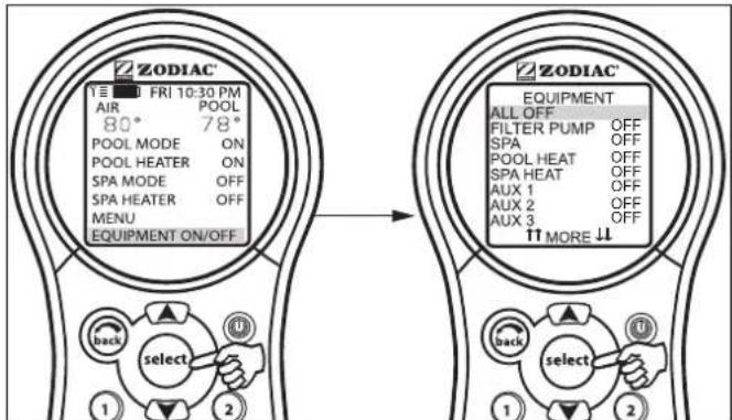
4.7.1 Equipment On/Off
Use this menu to manually turn a piece of equipment on or off. The ALL OFF mode will turn off equipment that has been turned on by any means (manual or pre-programmed). This includes any of the heater enables that were on (unless in use by the Maintain function).
4.7.2 To use Equipment On/Off
-
Highlight EQUIPMENT ON/OFF and press SELECT. To highlight an item, use the UP/DOWN arrow keys. Use the SELECT button to turn the equipment on or off. Return to the main menu by using the BACK button, or use the UP/DOWN arrow keys to highlight another device.
-
Highlight ALL OFF and press SELECT. After using ALL OFF, return to the main menu by using the BACK button.
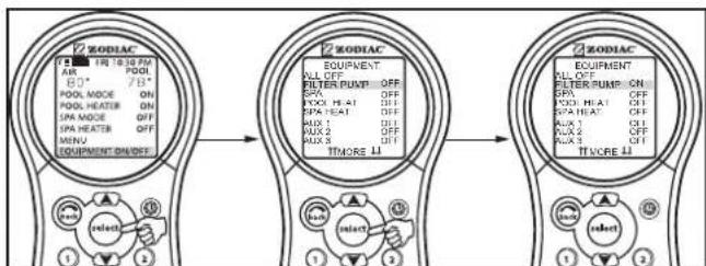
4.7.3 Filter Pump
The FILTER PUMP selection turns the main filtration pump on or off for circulation to the pool. The filter pump also activates if the spa is turned on, if the pool cleaner is turned on, or if the spa spill-over effect is activated. The main filtration pump circulates the pool or spa water through the filter and heater. The pump must be on if you want to display the pool temperature, or if you want to heat the pool.
See Section 4.3, for 2-speed operation.
4.7.4 To use Filter Pump
Highlight FILTER PUMP and press SELECT. Use the SELECT button to turn the equipment on or off.
flowchart
graph LR
    A["1 ZODIAC"] --> B["2 ZODIAC"]
    B --> C["3 ZODIAC"]

    A -->|PDL MODE ON, SPA HEATER OFF, MENU EQUIPMENT ON/OFF| A
    B -->|PDL MODE ON, SPA HEATER OFF, MENU EQUIPMENT ON/OFF| B
    C -->|PDL MODE ON, SPA HEATER OFF, MENU EQUIPMENT ON/OFF| C

    A -->| select 1| A
    A -->| select 2| A
    B -->| select 1| B
    B -->| select 2| B
    C -->| select 1| C
    C -->| select 2| C
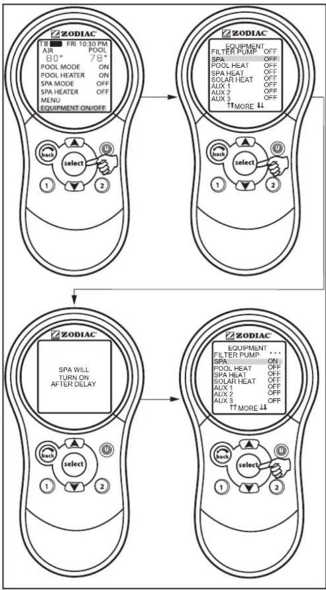
4.7.5 Spa
The SPA mode switches water circulation from the pool to spa (pool/spa combination models only). Turning on the spa also activates the filter pump (after a delay
for valve rotation) and deactivates the pool cleaner if it is on. The SPA mode must be on to display the spa temperature and/or to heat the spa. Activation takes place after a thirty second delay (while valves are turning).
4.7.6 To use Spa
Highlight SPA and press SELECT. Use the SELECT button to turn the spa on or off.
flowchart
graph TD
    A["Top Panel"] --> B["Top Panel"]
    B --> C["Bottom Panel"]
    C --> D["Bottom Panel"]
    D --> E["Top Panel"]
    style A fill:#f9f,stroke:#333
    style B fill:#f9f,stroke:#333
    style C fill:#f9f,stroke:#333
    style D fill:#f9f,stroke:#333
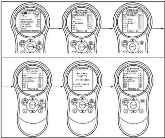
4.8 Pool Heat
The POOL HEAT selection enables the heater for the pool. It uses the setting from SET TEMP menu, or you can increase/decrease when enabling.
4.8.1 To use Pool Heat
Highlight FILTER PUMP and press SELECT. Highlight POOL HEAT and press SELECT. Use the UP/DOWN arrow keys to set the desired temperature and press SELECT.
flowchart
graph TD
    A["Top: ZODIAC"] --> B["Top: Equipment"]
    B --> C["Top: Equipment"]
    C --> D["Top: Equipment"]
    D --> E["Bottom: ZODIAC"]

    subgraph Top_Control
        A --> A1["Input: 10x20x20x30x30x30x30x30x30x30x30x30x30x30x30x30"]
        B --> B1["Select: 8"]
        B --> B2["Select: 6"]
        B --> B3["Select: 4"]
        B --> B4["Select: 2"]
        B --> B5["Select: 0"]
    end

    subgraph Bottom_Control
        C --> C1["Input: 8"]
        C --> C2["Select: 6"]
        C --> C3["Select: 4"]
        C --> C4["Select: 2"]
        C --> C5["Select: 0"]
    end

    subgraph Bottom_Control_Down
        D --> D1["Input: 8"]
        D --> D2["Select: 6"]
        D --> D3["Select: 4"]
        D --> D4["Select: 2"]
        D --> D5["Select: 0"]
    end

    style Top_Control fill:#f9f,stroke:#333
    style Bottom_Control fill:#bbf,stroke:#f66
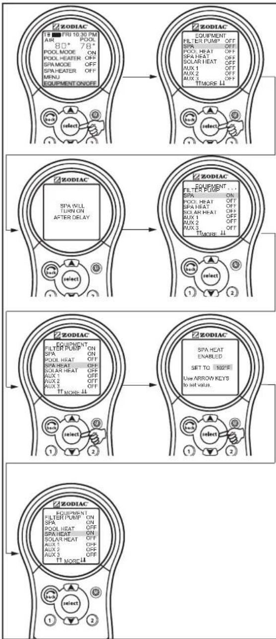
4.9 Spa Heat
The SPA HEAT enables the heater for the spa. The desired temperature can be set from the SET TEMP menu, or you can increase/decrease the temperature when enabling the heater.
4.9.1 To use Spa Heat
Highlight SPA and press SELECT. The spa will come on after a short delay. Highlight SPA HEAT and press SELECT. Use the UP/DOWN arrow keys to set the desired temperature and press SELECT.
flowchart
graph TD
    A["TR FRI 10:30 PM AIR 80° 78° POOL MODE ON POOL HEATER OFF SPA MODE OFF SPA HEATER OFF MENU EQUIPMENT ON/OFF"] --> B["ZODIAC"]
    B --> C[" select "]
    C --> D[" ZODIAC "]
    D --> E[" SPA WILL TURN ON AFTER DELAY "]
    E --> F[" ZODIAC "]
    F --> G[" FILTER PUMP ON SPA ON POOL HEAT OFF SPA HEAT OFF SOLAR HEAT OFF AUX 1 OFF AUX 2 OFF AUX 3 OFF TT MORE ↑↓ "]
    G --> H[" EQUIPMENT ON SPA HEAT ON OFF SPA HEAT OFF SOLAR HEAT OFF AUX 1 OFF AUX 2 OFF AUX 3 OFF TT MORE ↑↓ "]
    H --> I[" ZODIAC "]
    I --> J[" SET TO 102°F Use ARROW KEYS to set VALUE. "]
    J --> K[" Select "]
    K --> L[" Equipment ON SPA HEAT ENABLED SET TO 102°F Use ARROW KEYS to set VALUE. "]
    L --> M[" ZODIAC "]
    M --> N[" Select "]
    N --> O[" Equipment ON SPA HEAT ENABLED SET TO 102°F Use ARROW KEYS to set VALUE. "]
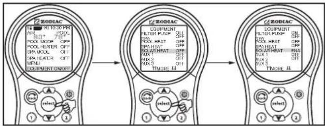
4.10 Solar Heat
The SOLAR HEAT selection controls solar heating. A solar heating system and optional solar sensor are required for SOLAR HEAT selection to operate and must be part of the normal circulation system.
4.10.1 To use Solar Heat
Highlight SOLAR HEAT and press SELECT. Use the SELECT button to turn SOLAR HEAT on or off.
For solar heating to take place, the SOLAR HEAT (in EQUIPMENT ON/OFF) must be enabled, also the filter pump must be on. Solar temperature must be at least 5°F (-15°C) above the water temperature and the water must be cooler than the thermostat setting.
NOTE If no Solar Sensor is installed, EXTRA AUX will appear as a menu item.
flowchart
graph LR
    A["Input: AIR 10:30 PM"] --> B["Filter Pump OFF"]
    B --> C["SOX HEAT OFF"]
    C --> D["BAS HEAT OFF"]
    D --> E["BAS HEAT OFF"]
    E --> F["AUX 2 OFF"]
    F --> G["AUX 3 OFF"]
    G --> H["THORE 44"]
    H --> I["Output: AIR 10:30 PM"]
NOTE If no Solar Sensor is installed, EXTRA AUX will appear as a menu item.
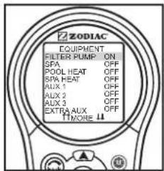
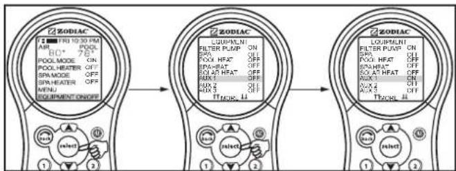
4.11 Auxiliary Equipment
The AUX modes control each of the auxiliary devices plus an extra AUX. To assign a different name to an auxiliary device, use the SYSTEM SETUP and LABEL AUX menus.
NOTE Auxiliary devices are items or equipment such as pool and spa lights, waterfalls, or air blowers.
4.11.1 To turn an Auxiliary on or off
Highlight EQUIPMENT ON/OFF and press SELECT. Highlight an AUX and press SELECT. Use the SELECT button to turn the equipment on or off.
flowchart
graph LR
    A["AIR"] --> B["POOL"]
    B --> C["POOL MODE ON"]
    C --> D["POOL HEATER OFF"]
    D --> E["SPA MODE OFF"]
    E --> F["SPA HEATER OFF"]
    F --> G["MENU"]
    G --> H["EQUIPMENT ON/OFF"]

    I["POOL MODE"] --> J["FILTER PUMP ON"]
    J --> K["SPA OFF"]
    K --> L["POOL HEAT OFF"]
    L --> M["SPA HEAT OFF"]
    M --> N["SOLAT HEAT OFF"]
    N --> O["AUX 1 OFF"]
    O --> P["AUX 2 OFF"]
    P --> Q["TIME Mode LL"]

    R["ZODIAC"] --> S["POUPLMENT"]
    S --> T["FILTER PUMP ON"]
    T --> U["SPA OFF"]
    U --> V["POOL HEAT OFF"]
    V --> W["SOLAT HEAT OFF"]
    W --> X["AUX 1 OFF"]
    X --> Y["AUX 2 OFF"]
    Y --> Z["TIME Mode LL"]
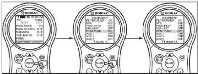
4.12 Heat Pump
NOTE This equipment may not be part of your system. Please check with your installer. The label HEAT PUMP may take up to 24 hours to appear on the screen after initial heat pump installation.
The HEAT PUMP selection controls the heat pump operation. In order to use the heat pump, the filter pump must be turned on and the heat pump must be in HEAT MODE (See Section 5.10), and the switch on the heat pump on the equipment pad must also be set to HEAT MODE.
NOTE HEAT PUMP takes the place of EXTRA AUX or SOLAR HEAT. It is not possible to have any two of these on the EQUIPMENT ON/OFF menu at the same time.
4.12.1 To use Heat Pump
Highlight EQUIPMENT ON/OFF and press SELECT. Highlight HEAT PUMP and press SELECT. Press the SELECT button to enable/disable the HEAT PUMP. The HEAT PUMP uses the SET TEMP set point.
flowchart
graph LR
    A["Top 1: AIR TFI 10:30 PM"] --> B["Top 2: EQUIPMENT ON/OFF"]
    B --> C["Top 3: EQUIPMENT ON/OFF"]
    A --> D["Bottom 1: POUO PEER 8.0° 7.9°"]
    B --> E["Bottom 2: POUO HEATER OFF SPA MODE OFF SPAHEATER OFF MENU EQUIPMENT ON/OFF"]
    C --> F["Bottom 3: POUO PEER 10.0° OFF SPA HEATER OFF SPA MODE OFF"]
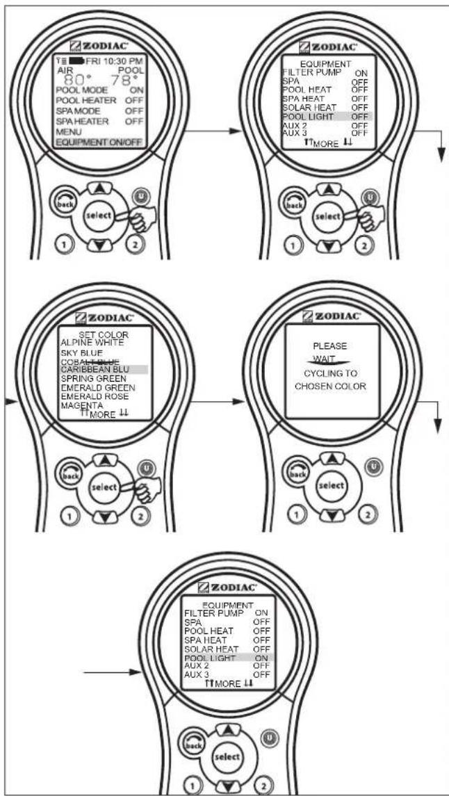
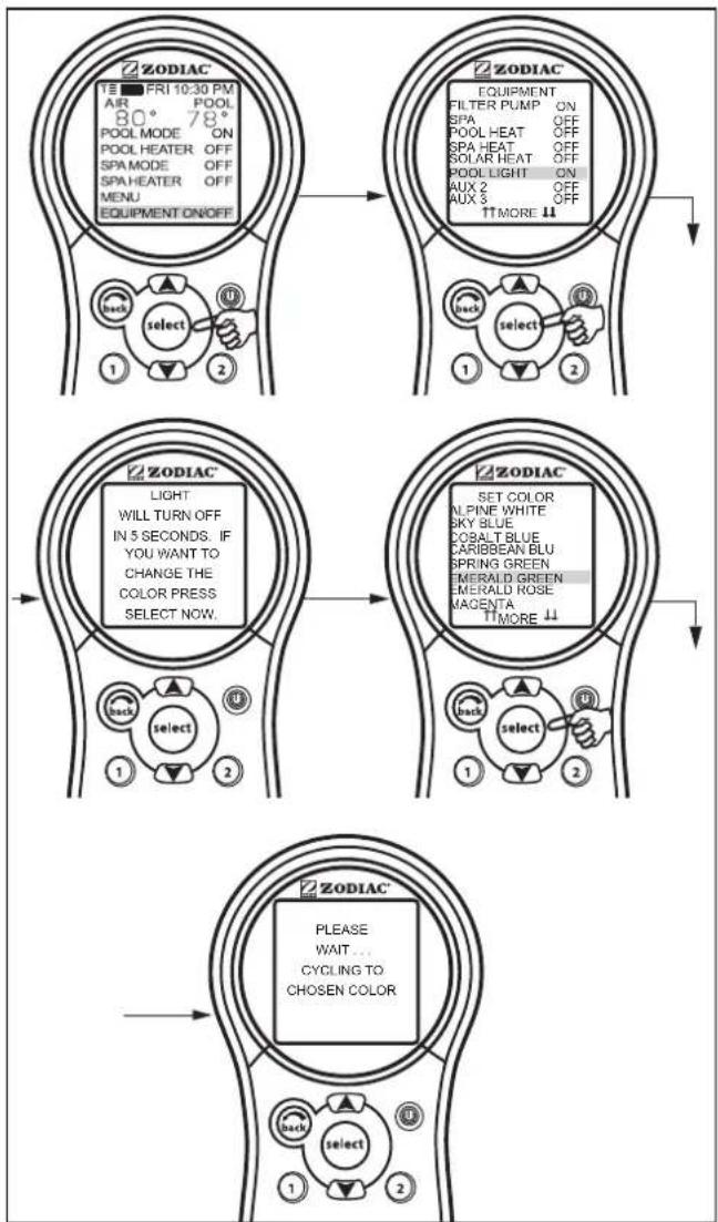
4.13 Set Light Colors
NOTE This equipment may not be part of your system. Please check with your installer.
The SET COLOR menu is used to set the color of a color light and then turn the light on.
NOTE Prior to setting the color of the light, the light must be assigned and controlled by an auxiliary (for example, AUX 1). See "Using System Setup" to assign the light to an auxiliary control. Please note that the auxiliary control can be custom labeled.
4.13.1 To use Set Colors
Highlight EQUIPMENT ON/OFF and press SELECT. Highlight the auxiliary assigned to the color light and press SELECT. A list of available colors will be displayed. The most recently selected color will be highlighted. Use the UP/DOWN arrow keys to highlight the desired color and press SELECT.
flowchart
graph TD
    A["1: FRI 10:30 PM AIR 80° 78° POOL MODE ON SPA HEATER OFF SPA HEATER OFF MENU EQUIPMENT ON/OFF"] --> B["2: Select"]
    B --> C["3: Select"]
    C --> D["4: Select"]
    D --> E["5: Select"]
    E --> F["6: Select"]
    F --> G["7: Select"]
    G --> H["8: Select"]
    H --> I["9: Select"]
    I --> J["10: Select"]
    J --> K["11: Select"]
    K --> L["12: Select"]
    L --> M["13: Select"]
    M --> N["14: Select"]
    N --> O["15: Select"]
    O --> P["16: Select"]
    P --> Q["17: Select"]
    Q --> R["18: Select"]
    R --> S["19: Select"]
    S --> T["20: Select"]
    T --> U["21: Select"]
    U --> V["22: Select"]
    V --> W["23: Select"]
    W --> X["24: Select"]
    X --> Y["25: Select"]
    Y --> Z["26: Select"]
    Z --> AA["27: Select"]
    AA --> AB["28: Select"]
    AB --> AC["29: Select"]
    AC --> AD["30: Select"]
    AD --> AE["31: Select"]
    AE --> AF["32: Select"]
    AF --> AG["33: Select"]
    AG --> AH["34: Select"]
    AH --> AI["35: Select"]
    AI --> AJ["36: Select"]
    AJ --> AK["37: Select"]
    AK --> AL["38: Select"]
    AL --> AM["39: Select"]
    AM --> AN["40: Select"]
    AN --> AO["41: Select"]
    AO --> AP["42: Select"]
    AP --> AQ["43: Select"]
    AQ --> AR["44: Select"]
    AR --> AS["45: Select"]
    AS --> AT["46: Select"]
    AT --> AU["47: Select"]
    AU --> AV["48: Select"]
    AV --> AW["49: Select"]
    AW --> AX["50: Select"]
    AX --> AY["51: Select"]
    AY --> AZ["52: Select"]
    AZ --> BA["53: Select"]
    BA --> BB["54: Select"]
    BB --> BC["55: Select"]
    BC --> BD["56: Select"]
    BD --> BE["57: Select"]
    BE --> BF["58: Select"]
    BF --> BG["59: Select"]
    BG --> BH["60: Select"]
    BH --> BI["61: Select"]
    BI --> BJ["62: Select"]
    BJ --> BK["63: Select"]
    BK --> BL["64: Select"]
    BL --> BM["65: Select"]
    BM --> BN["66: Select"]
    BN --> BO["67: Select"]
    BO --> BP["68: Select"]
    BP --> BQ["69: Select"]
    BQ --> BR["70: Select"]
    BR --> BS["71: Select"]
    BS --> BT["72: Select"]
    BT --> BU["73: Select"]
    BU --> BV["74: Select"]
    BV --> BW["75: Select"]
    BW --> BX["76: Select"]
    BX --> BY["77: Select"]
    BY --> BZ["78: Select"]
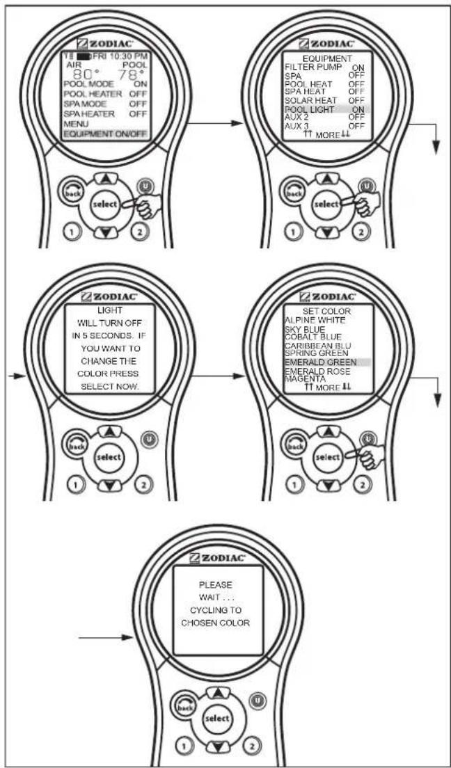
NOTE If you select POOL LIGHT or SPA LIGHT from the EQUIPMENT ON/OFF menu and the light is already ON, pressing SELECT will display the message "LIGHT WILL TURN OFF IN 5 SECONDS. IF YOU WANT TO CHANGE THE COLOR PRESS SELECT NOW". If you press SELECT, the SET COLOR menu will open and allow you to select a different color. If a different color is chosen, the light will reset to Alpine White, rotate to the selected color, and then automatically lock on to that color. During the color rotation, the message "PLEASE WAIT... CYCLING TO CHOSEN COLOR" will be displayed.
When a pool or spa light is turned ON manually, by the PDA Handheld Remote panel, or by a program, the last used color will automatically be chosen unless you press SELECT to change the color.
If you press the BACK key when in the EQUIPMENT ON/OFF menu, the light will turn on the last selected color. If the SELECT key or the BACK key is not pressed, and if it has been
15 seconds since the UP/DOWN keys have been pressed, then the most recently selected color will be selected again.
flowchart
graph TD
    A["1: ZODIAC EQUIPMENT ON/OFF"] --> B["2: ZODIAC FILTER PUMP ON SPA OFF POOL HEAT OFF SPA HEAT OFF SOLAR HEAT OFF POOL LIGHT ON AUX 2 AUX 3 OFF ↑↑ MORE ↓↓"]
    B --> C["3: ZODIAC LIGHT WILL TURN OFF IN 5 SECONDS. IF YOU WANT TO CHANGE THE COLOR PRESS SELECT NOW."]
    C --> D["4: ZODIAC SET COLOR ALPINE WHITE SKY BLUE COBALT BLUE CARIBBEAN BLU SPRING GREEN EMERALD GREEN EMERALD ROSE MAGENTA ↑↑ MORE ↓↓"]
    D --> E["5: ZODIAC PLEASE WAIT... CYCLING TO CHOSEN COLOR"]
    E --> F["6: Select 1 back select 2 back 1 back 2"]
Important Information
Do not activate this feature unless you are certain that color lights are installed on your system
4.14 Variable Speed Pump
NOTE This equipment may not be part of your system. Please check with your installer.
The speed of a variable speed pump can be adjusted from the EQUIPMENT ON/OFF screen. In the example below the SPEED PRESET #3 is adjusted to 2750 RPM.
4.14.1 To adjust the Variable Speed Pump Setting
Highlight EQUIPMENT ON/OFF and press SELECT. Highlight VSP1 SPD ADJ and press SELECT. Highlight SPEED3 and press SELECT. Use the UP/DOWN arrow keys to set the desired speed and press SELECT to make
that speed setting take effect. Return to the main menu by using the BACK button.
flowchart
graph TD
    A["TE FRI 10:30 PM AIR 80° 78° POOL MODE ON POOL HEATER OFF SPA MODE OFF SPA HEATER OFF MENU EQUIPMENT ON/OFF"] --> B["1 back select 2"]
    B --> C["ZODIAC"]
    C --> D["1 back select 2"]
    D --> E["2 back select 2"]
    E --> F["ZODIAC"]
    F --> G["1 back select 2"]
    G --> H["2 back select 2"]
    H --> I["ZODIAC"]
    I --> J["1 back select 2"]
    J --> K["2 back select 2"]
    K --> L["ZODIAC"]
    L --> M["1 back select 2"]
    M --> N["2 back select 2"]
    N --> O["ZODIAC"]
    O --> P["1 back select 2"]
    P --> Q["2 back select 2"]
    Q --> R["ZODIAC"]
    R --> S["1 back select 2"]
    S --> T["2 back select 2"]
    T --> U["ZODIAC"]
NOTE Speed adjustments from the EQUIPMENT ON/OFF screen are not permanent.
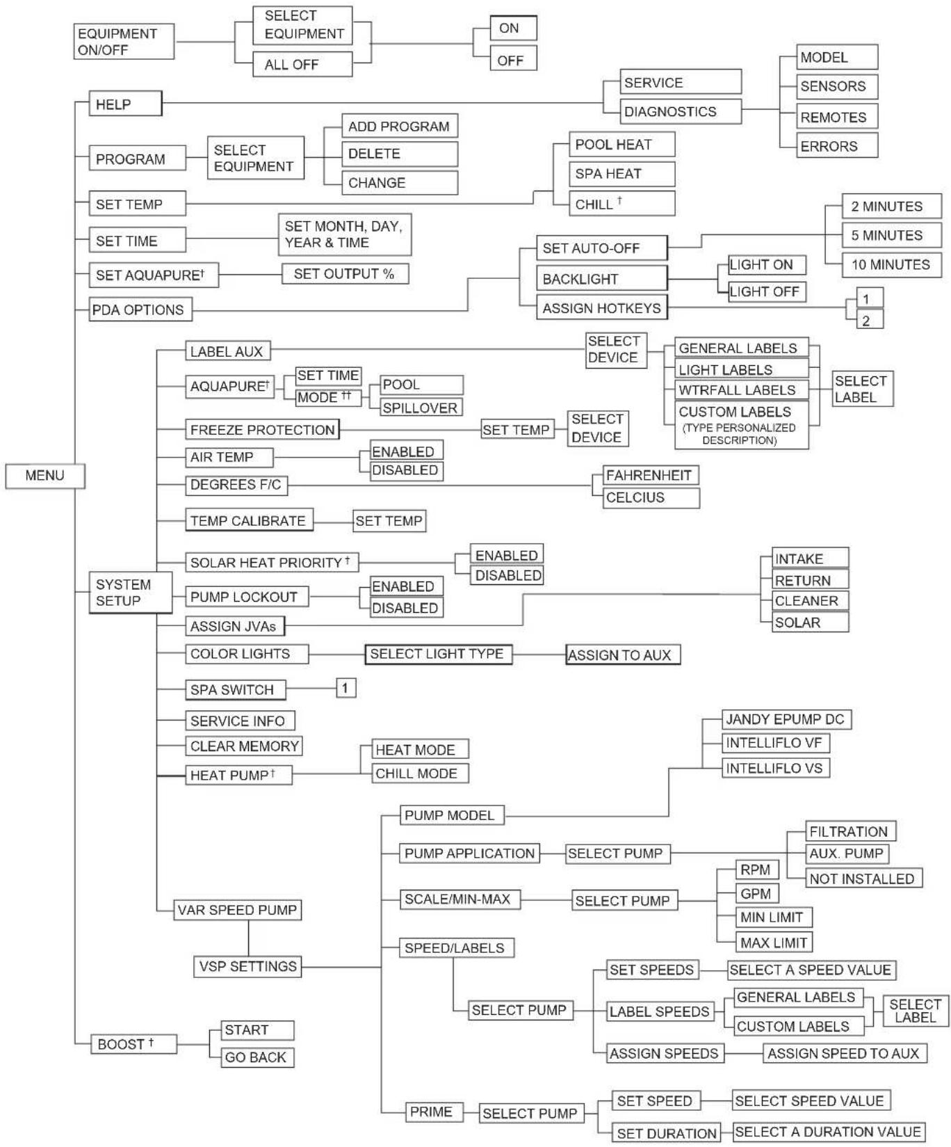
Section 5. PDA Handheld Remote Menu Flow Chart
flowchart
System setup flowchart detailing menu, system setup, and boost actions with key components like selection equipment, temperature settings, and control signals.^ Items Seen Only With Optional Equipment
* Items Seen Only In Revision "M"
** Not Available on Export Models
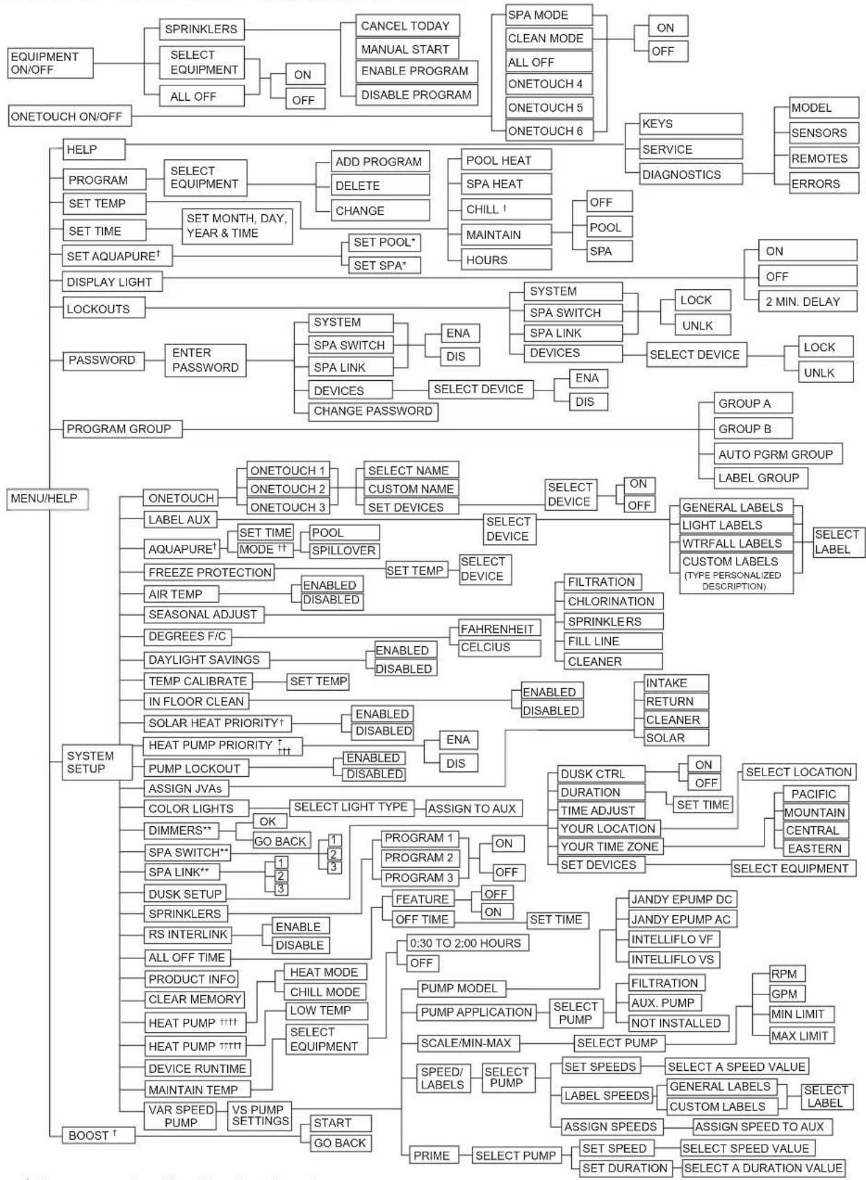
Section 6. OneTouch™ Menu Flow Chart
flowchart
graph TD
    A["EQUIPMENT ON/OFF"] --> B["ONETOUCH ON/OFF"]
    B --> C["HELP"]
    C --> D["PROGRAM"]
    D --> E["SET TEMP"]
    E --> F["SET TIME"]
    F --> G["SET AQUAPURE†"]
    G --> H["DISPLAY LIGHT"]
    H --> I["LOCKOUTS"]
    I --> J["PASSWORD"]
    J --> K["ENTER PASSWORD"]
    K --> L["PROGRAM GROUP"]

    L --> M["MENU/HELP"]
    M --> N["SYSTEM SETUP"]
    N --> O["BOOST†"]

    O --> P["SELECT EQUIPMENT"]
    P --> Q["ADD PROGRAM"]
    Q --> R["DELETE"]
    R --> S["CHANGE"]
    S --> T["SET POOL*"]
    T --> U["SET SPA*"]

    U --> V["SYSTEM"]
    V --> W["SPA SWITCH"]
    V --> X["SPA LINK"]
    V --> Y["DEVICES"]
    Y --> Z["CHANGE PASSWORD"]

    Z --> AA["ONETOUCH 1"]
    AA --> AB["ONETOUCH 2"]
    AB --> AC["ONETOUCH 3"]

    AC --> AD["ONETOUCH 1"]
    AD --> AE["CUSTOM NAME"]
    AE --> AF["SET DEVICES"]

    AF --> AG["SELECT DEVICE"]
    AG --> AH["ON OFF"]

    AH --> AI["GENERAL LABELS"]
    AI --> AJ["LIGHT LABELS"]
    AI --> AK["WTRFALL LABELS"]
    AI --> AL["CUSTOM LABELS (TYPE PERSONALIZED DESCRIPTION)"]

    AL --> AM["SELECT LABEL"]

    M --> AN["AQUAPURE†"]
    AN --> AO["FREEZE PROTECTION"]
    AO --> AP["AIR TEMP"]
    AP --> AQ["SEASONAL ADJUST"]
    AQ --> AR["DEGREES F/C"]
    AR --> AS["DAYLIGHT SAVINGS"]
    AS --> AT["TEMP CALIBRATE"]
    AT --> AU["IN FLOOR CLEAN"]
    AU --> AV["SOLAR HEAT PRIORITY†"]
    AV --> AW["HEAT PUMP PRIORITY †††"]
    AW --> AX["PUMP LOCKOUT"]
    AX --> AY["ASSIGN JVAs"]

    AY --> AZ["COLOR LIGHTS"]
    AZ --> BA["DIMMERS**"]
    BA --> BB["SPA SWITCH**"]
    BB --> BC["SPA LINK**"]
    BC --> BD["DUSK SETUP"]
    BD --> BE["SPRINKLERS"]
    BE --> BF["RS INTERLINK"]
    BF --> BG["ALL OFF TIME"]

    BQ["PRODUCT INFO"] --> BH["CLEAR MEMORY"]
    BH --> BI["HEAT PUMP ††††"]
    BI --> BJ["DEVICE RUNTIME"]
    BJ --> BK["MAINTAIN TEMP"]

    BL["VS PUMP SETTINGS"] --> BM["START GO BACK"]

    BN["START"] --> BO["GO BACK"]

    BP["SELECT PUMP"] --> BQ
    BP --> BS["SELECT PUMP"]

    BT["SPEED/LABELS"] --> BU["SPEED/LABELS"]

    BV["SPEED/LABELS"] --> BW["SPEED/LABELS"]

    BX["SPEED/LABELS"] --> BY["SPEED/LABELS"]

    CA["SPEED/LABELS"] --> CB["SPEED/LABELS"]

    CC["SPEED/LABELS"] --> DD["SPEED/LABELS"]

    DA["SPEED/LABELS"] --> DB["SPEED/LABELS"]

    DC["SPEED/LABELS"] --> DD

    EV["SPEED/LABELS"] --> DD

    EA["SPEED/LABELS"] --> DD

    BF["SPEED/LABELS"] --> DD

    BG["SPEED/LABELS"] --> DD

    BH["SPEED/LABELS"] --> BH

    BI["SPEED/LABELS"] --> BI

    BJ["SPEED/LABELS"] --> BJ

    BB["SPEED/LABELS"] --> BJ

    CC["SPEED/LABELS"] --> CC

    DQ["SPEED/LABELS"] --> DQ

    EE["SPEED/LABELS"] --> EE

    FQ["SPEED/LABELS"] --> FQ

    GG["SPEED/LABELS"] --> GG

    BHQ["SPEED/LABELS"] --> BHQ

    BIQ["SPEED/LABELS"] --> BIQ

    BBQ["SPEED/LABELS"] --> BBQ

    CCQ["SPEED/LABELS"] --> CCQ

    DDQ["SPEED/LABELS"] --> DDQ

    BEQ["SPEED/LABELS"] --> BEQ

    BBQ["SPEED/LABELS"] --> BBQ

    DQQ["SPEED/LABELS"] --> DQQ

    BBQ["SPEED/LABELS"] --> BBQ

    DQQ["SPEED/LABELS"] --> DQQ

    BBQ["SPEED/LABELS"] --> BBQ

    DQQ["SPEED/LABELS"] --> BBQ

    DQQ["SPEED/LABELS"] --> BBQ

    DQQ["SPEED/LABELS"] --> BBQ

    DQQ["SPEED/LABELS"] --> BBQ

    DQQ["SPEED/LABELS"] --> BBQ

    DQQ["SPEED/LABELS"] --> BBQ

    DQQ["SPEED/LABELS"] --> BQ
^† Items seen only with optional equipment
^†† Mode only displayed when DIP switch S1-3 is set to ON
DIP switch S2-1 must be ON. See differences between heat pumps controlled via RS485 or solar pump relay
Heat pump is controlled via the solar pump relay
ttttt Heat pump is controlled via the RS485
* Items seen only in Revision "N" or later
** Not Available on Export Models
Section 7. Troubleshooting
7.1 OneTouch™ Quick Troubleshooting Guide
| Symptom Problem Possible Solution | ||
| Power center override switches operate when in service or time out mode, but the control panel is completely dead (no lights on, no display). | Power supply problem. Check connection of the outside two wires (red & green) of the four conductor cable. If wired correctly, check the voltage between these two wires. Voltage for an All button system should be 7+ VDC and for a OneTouch system, 8+ VDC (use the higher voltage for a mixed system). | |
| All LEDs are on at the control panel and the part # and revision letter of the control panel software are displayed. The override switches at the power center operate as they should. | Control panel is not communicating with the power center PCB. | Check the two center wires (black & yellow) of the four conductor cable. Also check the installation of the CPU Board on the power center PCB. If the PPD is not seated correctly the system will not communicate. |
| All LEDs are on at the control panel and the part # and revision letter are displayed, but override switches at the power center do not operate at all. | 1. Damaged or improperly installed CPU Board.2. Damaged power center PCB. | 1. Check alignment of the CPU Board.2. If CPU Board is installed correctly, replace the power center PCB. |
| Some buttons do not operate from the control panel, nor from the power center override switches. | Wrong CPU Board chip installed at the power center PCB. | Check part number and revision letter by pressing the reset button at the control panel. The second part number and revision letter displayed is for the CPU Board indicating which model. |
| System locked up. Microprocessor locked. Turn off power to the system and turn back on. | ||
| Programs do not run at the correct time. | AquaLink does not display correct time and date. | At the control panel set correct time and date. |
| One button on the Four Function Remote or SpaLink® RS does not operate. | Check programming first. If the Four Function Remote or SpaLink RS is programmed correctly, the button may be shorted. | Replace the Four Function Remote or SpaLink RS. Use MENU, REVIEW, SPA SWITCH (or SPA LINK) to check programming. |
| Pool cleaner booster pump turns on without the filter pump being on, and can run with the spa on. | System is not recognizing DIP switch S1-1 is on. Note: before turning on any DIP switches, first turn off all equipment. | Turn off all equipment buttons, then turn off power to the system, finally turn off, then on, DIP switch S1-1. Turn on power and test system. |
| Model is one of the AquaLink M8 Dual Equipment, message scrolls "ADJUSTABLE FREEZE SENSOR NOT INSTALLED". System comes on at times that are not programmed. | Normal operation when a Dual Equipment AquaLink M8 is controlling a solar system and an adjustable freeze sensor is not installed. | Either install the adjustable freeze sensor, or wait 24 hours and this message will go away. |
| System comes on at times that are not programmed. | Phantom programs. At the control panel press MENU, then scroll to REVIEW. Make note of all programs (the Four Function Remote setting, labels, and temperature settings) then turn off all DIP switches and go to the control panel. CLEAR MEMORY, reprogram and try system again. | |
| Heater will not fire. Heater LED will not light in "Service Mode". | Water temperature sensor not installed or defective. | Check water temperature sensor. |
Section 8. Power Center Wiring Diagram for Combos and Onlys
AquaLink® M8 Wiring Diagram

AquaLink® M8 Dual Control Wiring Diagram
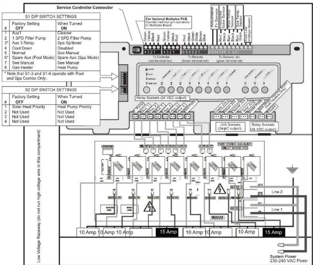
Section 9. Power Center PCB DIP Switch Settings
9.1 DIP Switch Functions
S1 DIP #1 ON-AUX 1 Controls Pool Cleaner
If you installed a booster pump for a pool cleaner, the relay coil for the booster pump must be plugged into the AUX 1 relay socket. If a non-booster pump cleaner is installed, plug the JVA into the cleaner JVA socket. Turn ON DIP Switch #1.
- Main filter pump turns on whenever cleaner turns on.
- Cleaner will not turn on until filter pump has been on for three (3) minutes (to ensure priming of system).
- Cleaner turns off when water circulation is to spa.
- Cleaner turns off when spa spillover feature is activated.
- Cleaner turns off for three (3) minutes when solar is activated (to ensure air is purged from the system).
- AquaLink M8 control panel display reads "CLEANER" rather than "AUX 1".
S1 DIP #2 ON- AUX 2 Controls Low Speed of Filter Pump
Turn this switch ON if you want to control both speeds of a two-speed filter pump. With this switch on, the filter pump button on the AquaLink M8 control panel will control high speed and the AUX 2 button will control low speed.
IMPORTANT You must also install a Jandy two-speed relay.
S1 DIP #3 ON- AUX 3 Controls Spa Spillover (Operates with Pool/Spa Combination)
Turn this switch ON, and when the AUX 3 button on the AquaLink M8 control panel (or spa side switch) is pressed, the return valve actuator will rotate to spa circulation. Because the intake valve actuator does not rotate, the spa will fill with water and overflow into the pool.
NOTE Leave AUX 3 relay socket empty.
S1 DIP #4 ON-Heater Cool Down Disabled
Turn this switch ON to disable the heater cool down safety feature on the AquaLink M8.
S1 DIP #5 ON- Factory Use Only
This switch is used for calibration by Jandy ^® certified technicians only. Please leave this switch in the OFF position.
WARNING
Turn this DIP Switch ON only if you are using an electric heater or a heat pump that does not retain residual heat. If you are turning this switch ON for service purposes, be sure to turn it back off to ensure that equipment operates as specified.
SI DIP #6 ON
Change spare AUX to activate when filter pump is on and system is in spa mode (pool/spa combination units only). Spare AUX socket is on the front side of the power center PCB.
S1 DIP #7 ON- Not Used
This switch only applies to DUAL EQUIPMENT systems. When OFF a separate heater is used for the pool and spa. When ON the pool and spa share the same heater.
S1 DIP #8 ON- Heat Pump Instead of Gas Heater
Turn this switch ON if you have installed a heat pump instead of a gas heater. After thermostat setting has been reached, heater will remain OFF for 5 minutes.
S2 DIP #1 ON- Heat Pump Priority
This switch is used for configuring solar priority or heat pump priority. Set this switch to ON if heat pump priority will be used. Set this switch to OFF if solar priority is to be used.
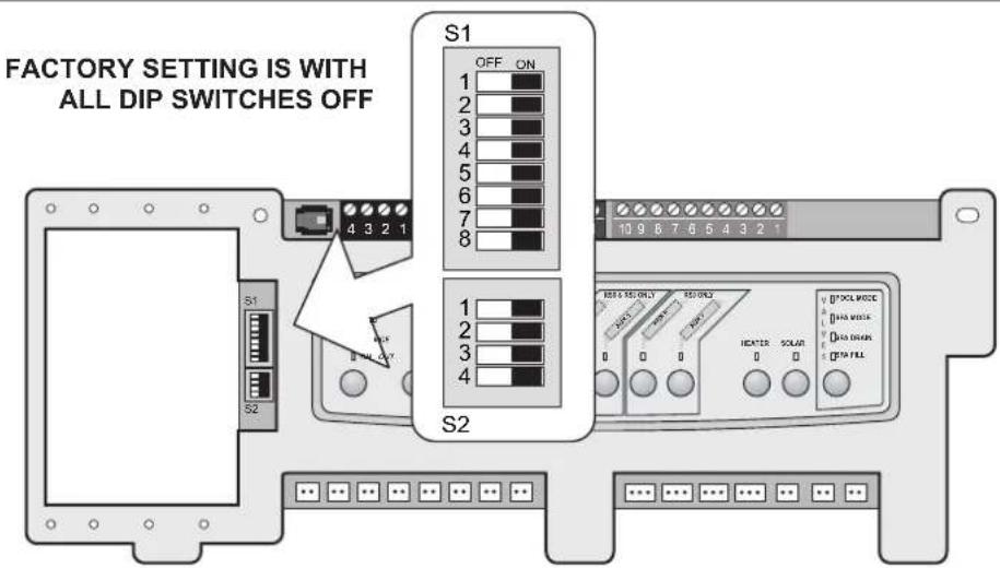
Figure 34. Factory DIP Switch Settings
9.2 DIP Switch Settings for Pool and Spa Combination
| S1 DIP Switch # | OFF | ON |
| 1 | AUX1= any equipment | AUX1= Pool Cleaner |
| 2 | AUX2= any equipment | AUX2= Low Speed for a two-speed filter pump.Filter pump circuit becomes High Speed. |
| 3 | AUX3= any equipment | AUX3= Spa Spillover effect- Combination controls only. |
| 4 | Heater cool down operates. | Heater cool down disabled. |
| 5 | Normal operation | Factory adjustment- when this switch is on, temperature delays are eliminated and solar temperature is displayed.Do not leave this switch in the ON position. |
| 6 | Spare Aux activates with Filter Pump when Spa OFF. | No change on Revision "HH" or older PPD. With revision "I" or newer, Spare AUX operation is reversed. |
| 7 | Spare | No change on Combination or Only Controls. |
| 8S2 DIP Switch # OFF ON | After thermostat setting has been reached, heater will remain OFF for three (3) minutes. | Heat Pump installed; after thermostat setting has been reached, heater will remain OFF for five (5) minutes. |
| 1 The AquaLink M8 will be able to control a Solar Heating system (If a solar sensor is connected to the solar sensor input). | The AquaLink M8 will be able to control a Heat Pump. (The AquaLink M8 will not be able to control a Solar Heating system.) | |
| 2 NOT USED | ||
| 3 NOT USED | ||
| 4 NOT USED | ||
9.3 DIP Switch Settings for Pool or Spa Only
| S1 DIP Switch # OFF ON | ||
| 1 AUX1= any equipment AUX1= Pool Cleaner | ||
| 2 AUX2= any equipment AUX2= Low Speed for a two-speed filter pump.Filter pump circuit becomes High Speed. | ||
| 3 AUX3= any equipment No change | ||
| 4 Heater cool down operates. Heater cool down disabled. | ||
| 5 Normal operation Factory adjustment- when this switch is on, temperature delays are eliminated and solar temperature is displayed.Do not leave this switch in the ON position. | ||
| 6 | Spare | No change |
| 7 | Spare | No change |
| 8 | After thermostat setting has been reached, heater will remain OFF for 3 minutes. | Heat Pump installed; after thermostat setting has been reached, heater will remain OFF for 5 minutes. |
| S2 DIP Switch # OFF ON | ||
| 1 | The AquaLink M8 will be able to control a Solar Heating system (If a solar sensor is connected to the solar sensor input). | The AquaLink M8 will be able to control a Heat Pump. (The AquaLink M8 will not be able to con-trol a Solar Heating system.) |
| 2 NOT USED | ||
| 3 NOT USED | ||
| 4 NOT USED | ||
9.4 DIP Switch Settings for Heat Pump Installation
This table shows how to configure the system for SOLAR PRIORITY or HEAT PUMP PRIORITY.
| DIP S2-1 | GREEN 10-PIN TERMINAL BAR | RS485 HEAT PUMP DESCRIPTION | |
| OFF No | sensor installed Not connected In this configuration | there is no Solar Heating and no Heat Pump. Extra AUX is available. | |
| OFF Sensor installed Not connected In this configuration there is Solar Heating and there is Solar Priority. There is no Heat Pump. | |||
| OFF Sensor installed Connected In this configuration there is Solar Heating and there is Solar Priority. There is Heat Pump. There is Heat Pump Priority. | |||
| ON No sensor installed Not connected In this configuration there is no Solar Heating. There is a mechanically connected Heat Pump. There is Heat Pump Priority (a limited implementation). | |||
| ON Sensor installed Not connected In this configuration there is no Solar Heating. There is a mechanically connected Heat Pump. There is Heat Pump Priority (full implementation). | |||
| ON Sensor installed Connected In this configuration there is no Solar Heating. There is an RS485 controlled Heat Pump. There is Heat Pump Priority. | |||
Section 10. General, Water Feature and Light Aux Labels

flowchart
graph TD
    A["Aerator\nAir Blower\nBackwash\nBooster Pump\nChem Feed\nCleaner\nColor Wheel\nDrain Line\nFan\nFiber Optic\nFill Line\nFilter Pump\nFloor System\nFogger\nFountain\nHeat Pump\nHeater\nHi-E2\nHigh Speed\nHome A/C\nHome Heat\nJet Pump\nJandy Lite\nJandy LX\nLamp\nLights*\nLow Speed\Mist\nMusic\nNot Used\nOzonator\npond\nRay-Vac\nSlide\nSolar Pump\nSpa\nSpillway\nSprinklers1\nSprinklers2\nSprinklers3\nStereo\nVanshng Edge\nSwim Jet\nTimed Aux\nValve(s)\nWtr Feature\nWaterfalls*\nWhirlpool\n* Item has sub-menu"] --> B["Laminar Jet\nWaterfall\nDeck Jets\nAqua Accents\nSconce\nShr Descent\nRockfall\nMain Labels"]
    C["#1 Light\n#2 Light\n#3 Light\nBack Light\nBasement Light\nBeach Light\nBedroom Light\nBug Light\nCabana Light\nColor Wheel Light\ndock Light\ndock Light\ndrive Light\neast Light\ntentry Light\nequipment Light\fan light\nfence light\nflood light\nfountain light\front light\ngarage light\ngarden light\ngazebo light\hall light\nc house light\nt kitchen light\nlaminar PIsr\nt Left light\ntight\north light\ntath light\ntatio light\ntperimeter light\ntpond light\ntool light\ntorch light\ntight light\ntwoon light\ntwoon light\ntwoon light\ntwoon light\ntwoon light\ntwoon light\ntwoon light\ntwoon light\ntwoon light\ntwoon light\ntwoon light\ntwoon light\ntwoon light\ntwoon light\ntwoon light\ntwoon light\ntwoon light\ntwoon light\ntwoon light\ntwoon light\ntwoo on the main label"] --> D["#1 Light\n#2 Light\n#3 Light\nBack Light\nBasement Light\nbeach Light\nBedroom Light\nBug Light\nCabana Light\nColor Wheel Light\ndock Light\ndock Light\ndrive Light\neast Light\ntery Light\ntery Light\nc house light\nto oon light\Laminar PIsr\ntleft light\ntight\north light\Path oon light\Patio light\Petimeter light\Pond light\Pool light\Porch light\righ right lightRoom light\Sauna light\Suniority light\nshower light\nshrub light\South light\spalight\ntitue Light\Stoes Light\ntable light\tier light\ntree light\walk lightWtr Feature Light\nto oon light\ntoon light\ntoon light\ntoon light\ntoon light\ntoon light\ntoon light\ntoon light\ntoon light\ntoon light\ntoon light\ntoon light\ntoon light\ntoon light\ntoon light\ntoon light\ntoon light\ntoon light\ntoon light\ntoon light\ntoon light\ntotw a t e l u t h e t h e t h e t h e t h e t h e t h e t h e t h e t h e t h e t h e t h e t h e t h e t h e t h e t h e t h e t h e t h e t h e t h e t h e t h e t h e t h e t h e t h e t h e t h e t h e t h e t h e n a l a b l e s"]
NOTES
NOTES
NOTES

Fluidra Group Australia
219 Woodpark Road,
Smithfield NSW2164, Australia
1.300.763.021 | www.zodiac.com.au
- AquaLink® M8
- For One Touch and PDA control systems
- WARNING
- EQUIPMENT INFORMATION RECORD
- Table of Contents
- Section 1. Important Safety Instructions.....4
- Section 2. System Overview....6
- Section 3. Installation....11
- Section 4. System Startup.... 19
- Section 1. Important Safety Instructions
- READ AND FOLLOW ALL INSTRUCTIONS
- DANGER
- To Reduce the Risk of Injury -
- CAUTION
- SAVE THESE INSTRUCTIONS
- Section 2. System Overview
- Package Contents
- Electrical Specifications
- Materials and Tools
- Installation Materials Furnished
- Dimensions
- Basic Plumbing
- Plumbing for Pool and Spa Combination
- Booster Pump Pool Cleaner Plumbing
- Basic Plumbing for Dual System
- Plumbing - Sharing One (1) Heater
- Section 3. Installation
- Power Center Mounting
- High Voltage Wiring
- System Power
- Bonding the Power Center
- Variable Speed Pump to Power Center PCB Cable
- Wiring the Pentair ® Pump
- Wiring the Zodiac ® ePump
- Zodiac ePump DIP switch settings
- Heater Connection
- Other Brands Heater and Pump Connections
- Temperature Sensors
- Jandy ® Pro Series Valve Actuators
- JVA Mounting Positions
- Actuator Mounting
- Synchronization JVAs
- Resetting the Cams
- OneTouch™ Control Panel Installation
- Surface Mount OneTouch Installation
- Flush Mount OneTouch Installation
- Multiple AquaLink M8 OneTouch Control Panel Installation
- AquaLink M8 OneTouch™ Control Panel Jumper Settings
- Section 4. System Startup
- OneTouch Programming
- Basic Programming
- Set the Time Menu
- MENU/HELP > SET TIME
- Set the Temperature
- Pool/Spa Combination
- MENU/HELP > SET TEMP > POOL or SPA > SET TEMP VALUE
- Pool/Spa Only
- MENU/HELP > SET TEMP > TEMP1 > SET TEMP1 VALUE > TEMP2 > SET TEMP2 VALUE
- Maintain Temperature
- MENU/HELP > SET TEMP > MAINTAIN
- Maintain Temperature Hours
- MENU/HELP > SET TEMP >HOURS
- Label Auxiliary Functions
- MENU/HELP > SYSTEM SETUP > LABEL AUX > AUX 1-X > CHOOSE LABEL TYPE > CHOOSE LABEL
- Set Freeze Protection
- MENU/HELP > SYSTEM SETUP > FREEZE PROTECT > SET TEMP VALUE > SELECT FREEZE PROTECT DEVICE
- Assign JVs
- MENU/HELP > SYSTEM SETUP > ASSIGN JAVAs > SELECT JVA
- Seasonal Adjust
- MENU/HELP > SYSTEM SETUP > SEASONAL ADJ > SELECT FILTRATION/SPRINKLERS/FILL LINE/CLEANER
- OneTouch™ Reset and Display Messages
- Restarting the System
- Variable Speed Pump Menu
- To select the Pump Type
- To set up the Pump Application
- MENU/HELP > SYSTEM SETUP > VSP SETTINGS > SELECT PUMP APPLICATION > SELECT PUMP1 > SELECT ITEM
- To set SCALE/MIN-MAX Parameters
- MENU/HELP > SYSTEM SETUP > VSP SETTINGS > SELECT MIN-MAX SETTINGS > SELECT PUMP1 > CHOOSE LIMIT
- To set Pump Speed
- MENU/HELP > SYSTEM SETUP > VSP SETTINGS > SELECT SPEED/LABELS > SET SPEEDS> CHOOSE SPEED
- To re-label the Speed Preset
- MENU/HELP > SYSTEM SETUP > VSP SETTINGS > SELECT SPEED/LABELS > LABELS SPEEDS> CHOOSE ITEM > SELECT GENERAL LABELS/CUSTOM LABELS
- Default Preset Speed Labels (RS Combo and RS only)
- Preset 1:
- Preset 2:
- Preset 3:
- Preset 4:
- Preset 5:
- Preset 6:
- Preset 7:
- Preset 8:
- Default Preset Speed Labels (Dual Equipment)
- Preset 1:
- Preset 2:
- Preset 3:
- Preset 4:
- Preset 5:
- Preset 6:
- Preset 7:
- Preset 8:
- OneTouch TM System Defaults and General Modes
- Power Center Service Switch
- AUTO Mode (automatic)
- SERVICE Mode
- TIMEOUT Mode
- Power Interruption
- ATTENTION
- PDA Installation
- AquaLink Transceiver J-box Installation
- AquaLink Handheld Remote Installation
- Changing the Frequency Channel
- PDA Handheld Remote System Defaults and General Modes
- Basic Functions
- Using the Buttons
- Battery Status
- Signal Strength
- PDA Handheld Remote On/Off Menu
- Equipment On/Off
- To use Equipment On/Off
- Filter Pump
- To use Filter Pump
- Spa
- To use Spa
- Pool Heat
- To use Pool Heat
- Spa Heat
- To use Spa Heat
- Solar Heat
- To use Solar Heat
- Auxiliary Equipment
- To turn an Auxiliary on or off
- Heat Pump
- To use Heat Pump
- Set Light Colors
- To use Set Colors
- Important Information
- Variable Speed Pump
- To adjust the Variable Speed Pump Setting
- Section 7. Troubleshooting
- OneTouch™ Quick Troubleshooting Guide
- Section 8. Power Center Wiring Diagram for Combos and Onlys
- Factory Setting ON
- Section 9. Power Center PCB DIP Switch Settings
- DIP Switch Functions
- DIP Switch Settings for Pool or Spa Only
- DIP Switch Settings for Heat Pump Installation
- Section 10. General, Water Feature and Light Aux Labels
- NOTES
Brand : ZODIAC
Model : AquaLink M8
Category : Pool Controller