PRO 1100 - TV signal amplifier Wilson - Free user manual and instructions
Find the device manual for free PRO 1100 Wilson in PDF.


| Product Type | TV Signal Amplifier |
| Brand | Wilson |
| Model | PRO 1100 |
| Dimensions (L x W x H) | 4.7 x 3.1 x 1.2 inches (120 x 80 x 30 mm) |
| Weight | 7.1 oz (200 g) |
| Power Supply | 12V DC, 500 mA (included adapter) |
| Frequency Range | VHF: 47-230 MHz, UHF: 470-862 MHz |
| Gain | 20 dB typical |
| Noise Figure | ≤ 3 dB |
| Input/Output Impedance | 75 Ohm |
| Number of Outputs | 2 (TV + FM) |
| Connector Type | F-type female |
| Max. Power Consumption | 6 W |
| Operating Temperature Range | -10°C to 50°C |
| Indoor/Outdoor Use | Indoor only |
| Warranty | 2 years |
| Maintenance | Wipe with a soft, dry cloth; do not use liquids |
| Safety | Keep away from moisture; unplug during storms |
| Spare Parts Available | Power adapter, mounting kit |
| Reparability | Repairable by qualified technician; no user-serviceable parts inside |
| Contents | Amplifier unit, power adapter, mounting screws, installation guide |
Frequently Asked Questions - PRO 1100 Wilson
User questions about PRO 1100 Wilson
0 question about this device. Answer the ones you know or ask your own.
Ask a new question about this device
Download the instructions for your TV signal amplifier in PDF format for free! Find your manual PRO 1100 - Wilson and take your electronic device back in hand. On this page are published all the documents necessary for the use of your device. PRO 1100 by Wilson.
USER MANUAL PRO 1100 Wilson
In-Building Cell Signal Amplifier
Installation Guide
Index
Package Contents 1
About The Pro 1100 2
Key Features 4
Post Install Setup 5
Menu System 7
Safety Guidelines 12
Warranty 17
Package Contents
Kit 460147 50Ω
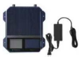
natural_image
Exterior view of a blue rectangular electronic device with a black cable and charging plug (no visible text or symbols)Pro 1100
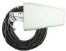
natural_image
Coiled black cable with a white rectangular device attached, no visible text or symbolsWide Band Directional Antenna + 75' Wilson 400 Cable
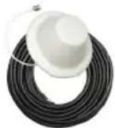
Dome Antenna + 60' Wilson 400 Cable
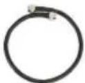
2' Wilson
400

Lightning Surge
Protector
Kit 461147 75Ω
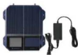
natural_image
Exterior view of a solar panel with connected charging cable and power cord (no text or symbols visible)Pro 1100
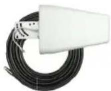
natural_image
Coiled black cable with a white rectangular connector attached (no visible text or symbols)Wide Band Directional Antenna + 75' RG11 Cable
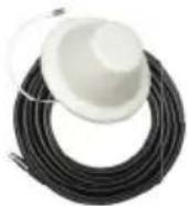
Dome Antenna + 50' RG11 Cable
2' Wilson
RG11

Lightning Surge
Protector
Pro 1100
In-Building Cell Signal Amplifier
natural_image
Tall metal tower against a clear blue sky, surrounded by green trees (no text or symbols visible)Up to +25 dBm uplink power for maintaining connections with far-away cell towers

natural_image
Man smiling while talking on a phone in an office setting (no visible text or symbols)Up to +15 dBm downlink power for improved indoor cell coverage area

eXtended Dynamic Range (XDR) for Continuous Connectivity
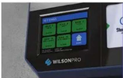
Color touch screen, for easy installation and displaying detailed amplifier status
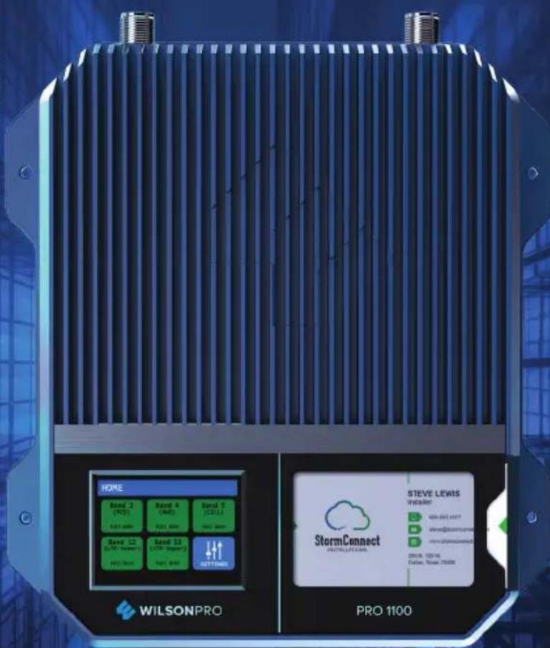
The Pro 1100 cell signal amplifi er system provides signifi cantly enhanced 4G LTE and XG voice and data coverage inside large homes and commercial buildings where cell signals may not otherwise penetrate. Installation of a Pro 1100 cell signal amplifi er system results in fewer dropped calls, improved voice quality, uninterrupted texts, and faster data speeds—along with better audio and video streaming. The Pro 1100 has been approved for use by the
FCC (U.S), ISED (Canada), and is carrier-accepted by all major mobile networks and providers in North America. No additional approvals or permissions are required.
natural_image
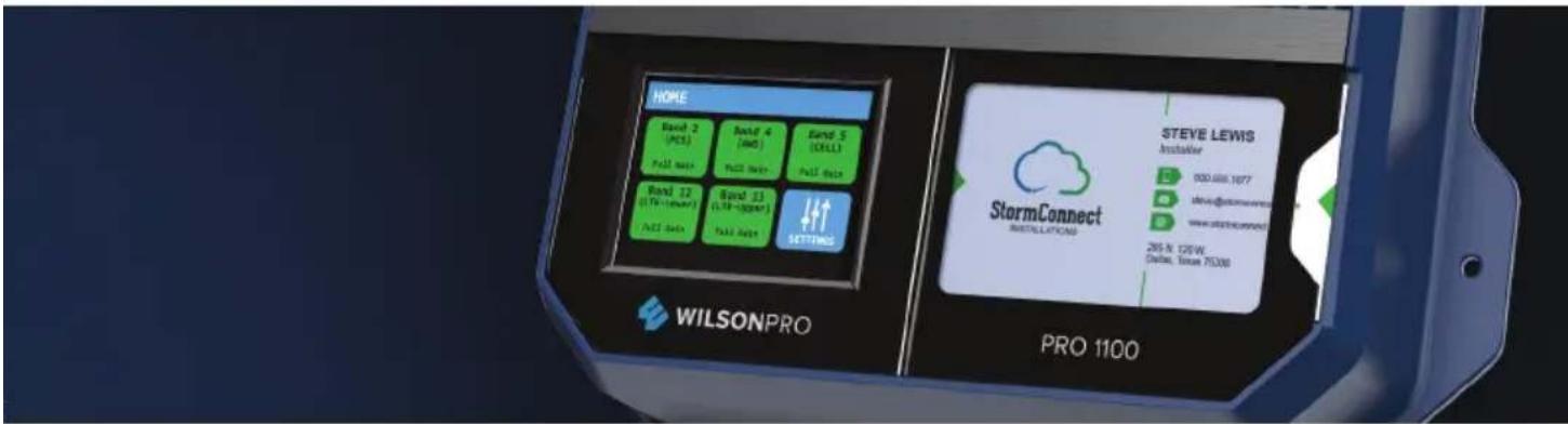
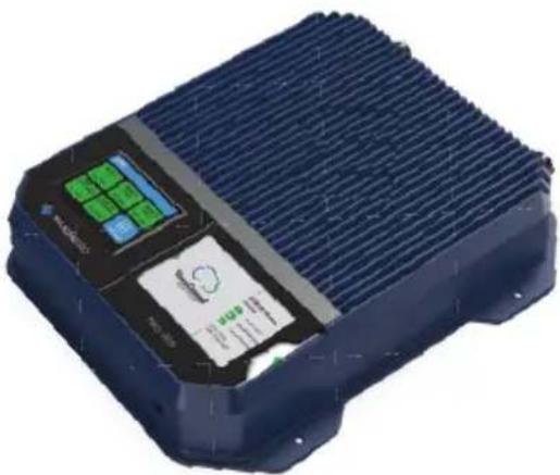
3D rendering of a blue industrial electronic device with green and blue buttons, no visible text or symbolsThe Pro 1100 also incorporates Wilson Electronics' state-of-the-art XDR (eXtended Dynamic Range) technology that prevents signal overload conditions which can, in accordance with regulations, force the amplifi er to shut down. When the Pro 1100 senses that any incoming cell signal is too strong and threatens to overload the system, XDR automatically reduces amplifi er gain to compensate while maintaining signal coverage throughout the building. The Pro 1100 incorporates an easy-to-use color LCD touch screen, and both antenna ports are located on the top of the unit for simple installation. Like all WilsonPro cell signal boosters, the Pro 1100 amplifi er system is universal: it works for all cellular devices, all services and all U.S. and Canada cell phone carriers.
Key
Features

Extended Dynamic Range (XDR) for continuous connectivity:
XDR lets the Pro 1100 system work with an incoming signal and never shuts down due to a strong outside signal.

Simple Wall-Mount Installation: An indoor and outdoor port are located on top of the amplifier for easy antenna connections, while an exposed mounting flange at each corner of the amplifier provides for simple and clean wall-mount installation.

Onboard Software for Better Control: The amplifier is automatically controlled with automatic onboard software, ensuring great connectivity throughout large spaces and multi-story buildings. The amplifier will adjust its gain level up or down as required by the conditions of the immediate signal environment.

Color LCD Touch Screen: The Pro 1100 utilizes a color LCD touch screen, for assessing amplifi er performance, making adjustments to the outside antenna, and turning bands on and off.
Post Install Setup
The Pro 1100 is designed with advanced internal programming, which allows it to automatically adjust for a variety of conditions, while still amplifying weak signals.
Once the antenna cables are connected, turn the unit on by connecting the power supply cord, at the bottom.
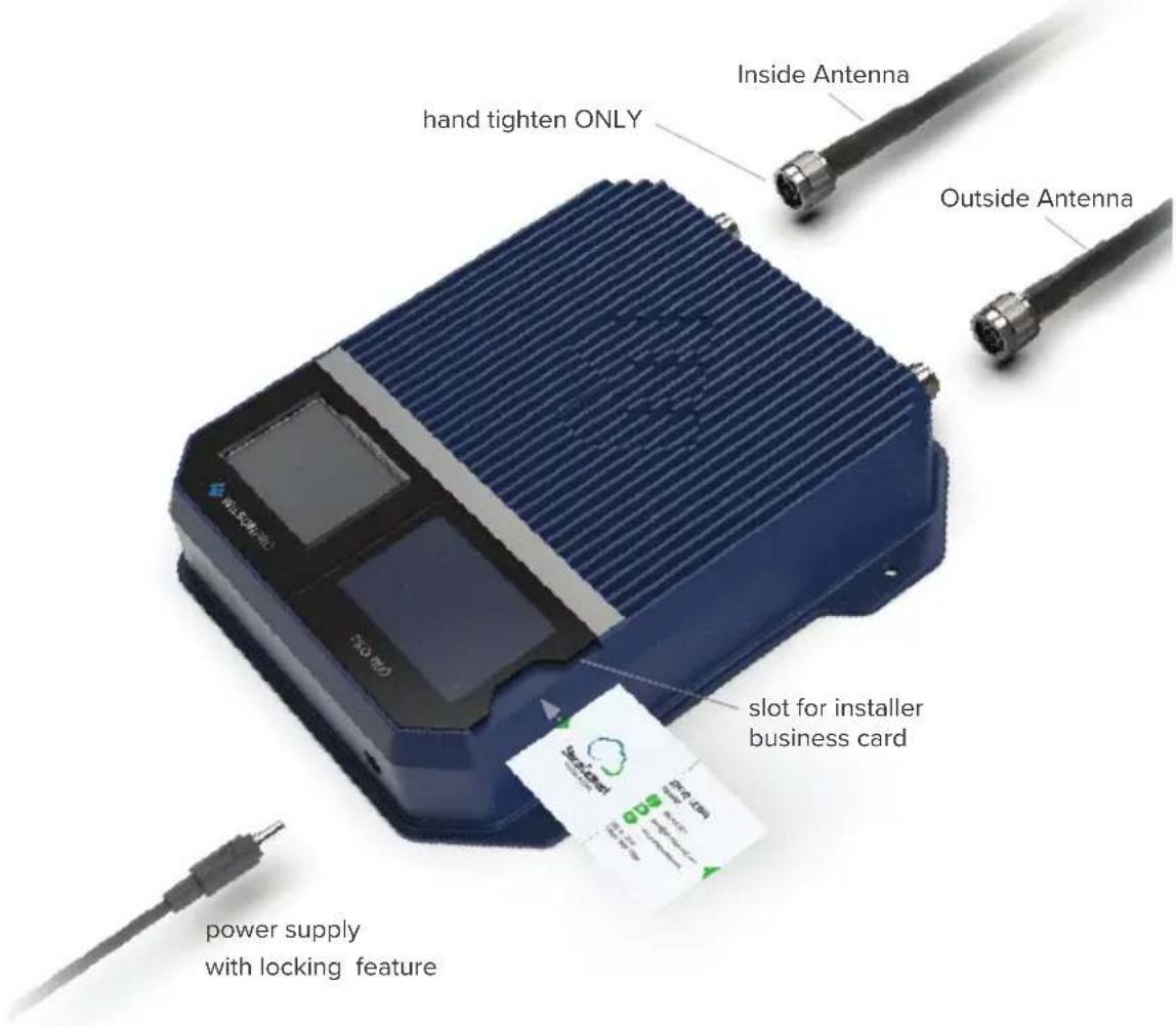
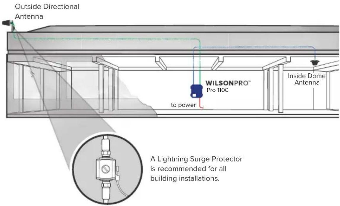
Installation Diagram
A Wilson Lightning Surge Protector is recommended for all building installations. Make sure the protector is installed outside the building. Connect it to suitable ground and in line, between the Outside Antenna and the Signal Amplifi er.
Menu System
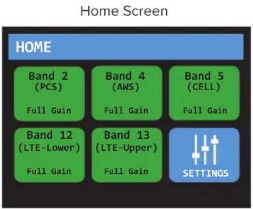
The Pro 1100 takes about 5 seconds to boot up. Once boot up is complete, the home screen will appear, showing the amplifi cation and status of each port and band.
Start Up Screen
Band Menu Color Description


A solid green light indicates that a band is operating correctly with maximum allowable gain.
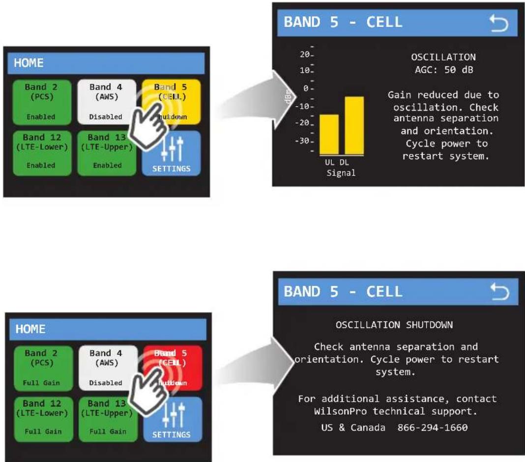
A solid yellow light indicates band gain reduction because of an oscillation condition. Reposition antennas (increase separation between indoor and outdoor antennas, and point in opposite directions) and then reboot (turn the unit off & on) the Pro 1100 to reactivate the band and maximize performance. When adequate separation is achieved, the yellow lights will return to green upon reboot.
Note: when the light is yellow, the band is operational; however, performance is reduced.
(MENU SYSTEM cont.)

A red light indicates a band has been shut down because of a severe oscillation condition or repeated oscillation. Reposition antennas (increase separation between indoor and outdoor antennas, and point in opposite directions) and then reboot (turn the unit off & on) the Pro 1100 to reactivate the band and maximize performance. When adequate separation is achieved, the red light(s) will return to green upon reboot.

Gray indicates band has been disabled.
Settings Screen
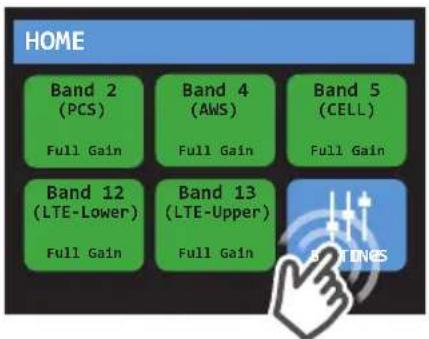
Tap icon to view the Settings Screen.
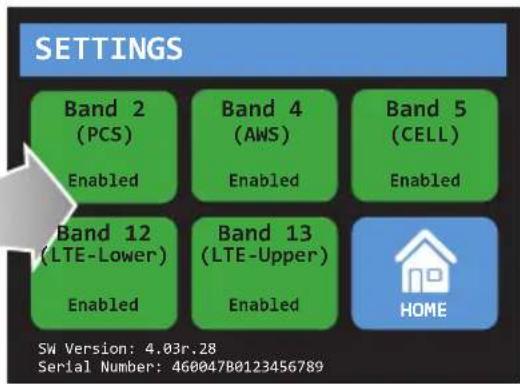
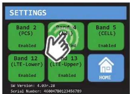
Bands can be disabled/enabled by tapping the desired band. Note: disabling a cell band is not recommended. Bands should only be disabled by expert installers.
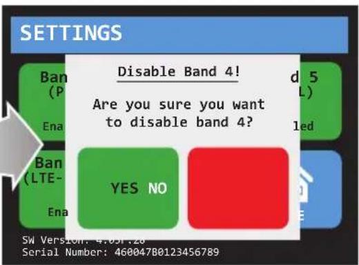
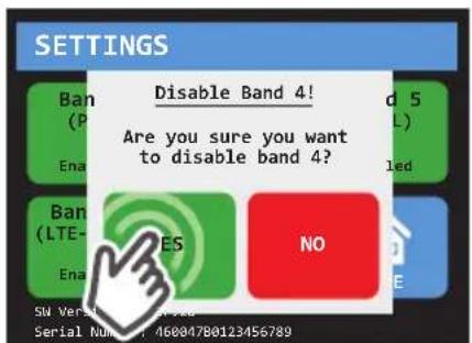
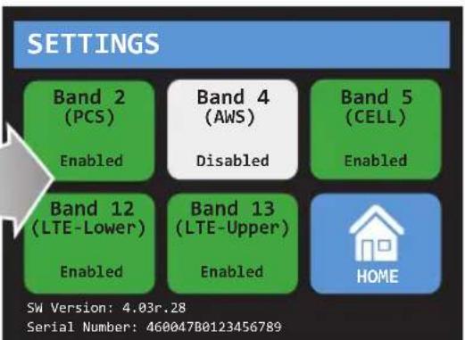
(MENU SYSTEM - SETTINGS SCREEN cont.)
To go back to the home screen tap on the home icon.
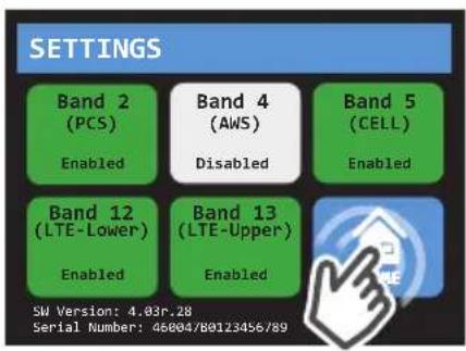
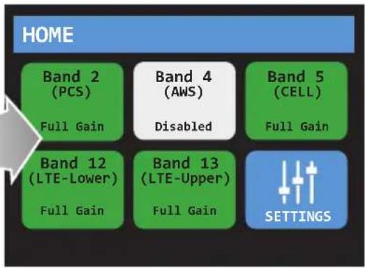
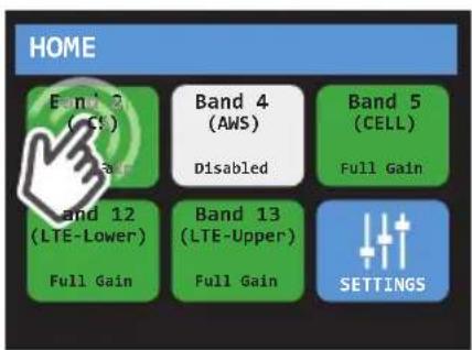
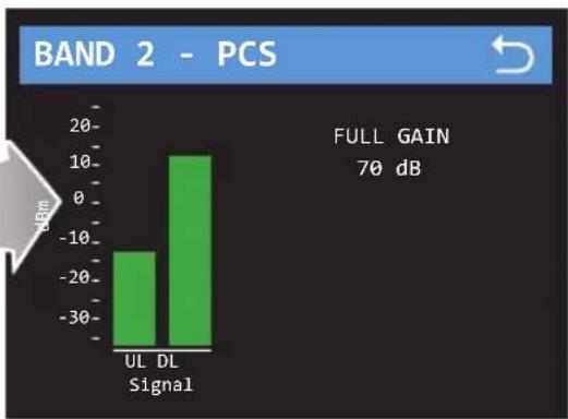
To view specific band information (such as the strength of the received uplink & downlink signal, status details and the amplifier gain) tap desired band on the home screen.
bar
BAND 2 - PCS | Signal | Full Gain (dB) | |---|---| | UL | -15 | | DL | 12 | FULL GAIN 70 dBNote: The direction of the outside antenna should be adjusted until the "DL" bar is maximized.
(MENU SYSTEM - SETTINGS SCREEN cont.)
By tapping on the desired Band, a more detailed screen will appear for better troubleshooting.
Safety Guidelines

Warnings
To uphold compliance with network protection standards, all active cellular devices must maintain at least 6 feet of separation distance from Panel and Dome antennas.
Use only the power supply provided in this package. Use of a non-Wilson Electronics product may damage your equipment.
The Signal Amplifi er unit is designed for use in an indoor, temperature-controlled environment (operating temperature ranges from -40^ to 60^ - - 40^ to 140^ ). It is not intended for use in attics or similar locations subject to temperatures in excess of that range.
RF Safety Warning: Any antenna used with this device must be located at least 8 inches from all persons.
AWS Warning: The Outside Antenna must be installed no higher than 10 meters (31'9") above ground.
This is a CONSUMER device.
BEFORE USE, you MUST REGISTER THIS DEVICE with your wireless provider and have your provider's consent. Most wireless providers consent to the use of signal boosters. Some providers may not consent to the use of this device on their network. If you are unsure, contact your provider.
You MUST operate this device with approved antennas and cables as specified by the manufacturer. Antennas MUST be installed at least 20 cm (8 inches) from any person.
You MUST cease operating this device immediately if requested by the FCC or licensed wireless service provider.
WARNING. E911 location information may not be provided or may be inaccurate for calls served by using this device.
This device may operate in a fixed location only, for in-building use.
FOR MORE INFORMATION ON REGISTERING YOUR SIGNAL AMPLIFIER WITH YOUR WIRELESS PROVIDER, PLEASE SEE BELOW:
Sprint: http://www.sprint.com/legal/fcc_boosters.html
T-Mobile/MetroPCS: https://support.t-mobile.com/docs/DOC-9827
Verizon Wireless: http://www.verizonwireless.com/wcms/consumer/register-signal-booster.html
AT&T: https://securec45.securewebsession.com/attsignalbooster.com/
U.S. Cellular: http://www.uscellular.com/uscellular/support/fcc-booster-registration.jsp
Antenna Kit Options
The following accessories are certified by the FCC to be used with the PRO 1100.
OUTSIDE FIXED
Kit 314411-40075
Wide Band Directional Antenna
With 75' Wilson 400
Kit 314411-5825
Wide Band Directional Antenna
With 25' RG-58
Kit 304422-1120
Omni Enterprise 304422 With
20' RG-11
Kit 301111-5850
Yagi Antenna 301111 With 50' RG-58
Kit 311203-40020
Omni Directional Antenna (311203)
With 20' Wilson 400
Kit 314453-5825
Panel Antenna With 25' RG-58
Kit 311203-5820
Omni Directional Antenna (311203)
With 20' RG-58
Kit 301111-11140
Yagi 301111 With 140' RG-11
Kit 311201-1120
Omni Directional Antenna 311201
With 20' RG-11
Kit 314453-40075
Panel Antenna With 75' Wilson 400
Kit 311141-1120
Grey Panel With 20' RG-11
Kit 314473-1175
Wide Band Directional Antenna
With 75' RG-11
Kit 314475-1175
Wide Band Directional Antenna
With 75' RG-11
Kit 301111-400170
Yagi Antenna 301111 With 170'
Wilson 400
Kit 304421-17410
Omni Consumer 304421 With
10' RG-174
Kit 304421-5810
Omni Consumer 304421 With
10' RG-58
Kit 304422-40020
Omni Enterprise 304422 With
20' Wilson 400
INSIDE FIXED
Kit 304412-40060
Dome w/60' Wilson 400
Kit 304419-1150
Dome w/50' RG-11
Specifications
| Model Number 460047 / 461047 | |||||
| FCC ID | PWO460047 | ||||
| IC ID | 4726A-460047 | ||||
| Connectors N-Female / F-Female | |||||
| Antenna Impedance 50 Ohms / 75 Ohms | |||||
| Frequency | 698-716 MHz, 729-746 MHz, 777-787 MHz, 824-894 MHz, 1850-1995 MHz, 1710-1755/2110-2155 MHz | ||||
| Power output for single cell phone (Uplink) dBm | 700MHz Band12/17 | 700MHz Band13 | 800MHz | 1700MHz | 1900MHz |
| 24.0 24.0 25.0 25.0 25.0 | |||||
| Power output for single cell phone (Downlink) dBm | 700MHz Band12/17 | 700MHz Band13 | 800MHz | 2100MHz | 1900MHz |
| 15.1 15.1 15.3 15.2 15.2 | |||||
| Noise Figure 5 dB nominal | |||||
| Isolation >90 dB | |||||
| Power Requirements | 120V AC 0.5A | ||||
Each Signal Booster is individually tested and factory set to ensure FCC compliance. The Signal Booster cannot be adjusted without factory reprogramming or disabling the hardware. The Signal Booster will amplify, but not alter incoming and outgoing signals in order to increase coverage of authorized frequency bands only. If the Signal Booster is not in use for five minutes, it will reduce gain until a signal is detected. If a detected signal is too high in a frequency band, or if the Signal Booster detects an oscillation, the Signal Booster will automatically turn the power off on that band. For a detected oscillation the Signal Booster will automatically resume normal operation after a minimum of 1 minute. After 5 (fi ve) such automatic restarts, any problematic bands are permanently shut off until the Signal Booster has been manually restarted by momentarily removing power from the Signal Booster. Noise power, gain, and linearity are maintained by the Signal Booster's microprocessor.
This device complies with Part 15 of FCC rules. Operation is subject to two conditions: (1) This device may not cause harmful interference, and (2) this device must accept any interference received, including interference that may cause undesired operation. Changes or modifications not expressly approved by weBoost could void the authority to operate this equipment.
Notes
NEED HELP?

support.wilsonpro.com 866294.1660
Notes
NEED HELP?

support.wilsonpro.com 866294.1660
Warranty

30 DAY MONEY-BACK GUARANTEE
All WilsonPro products are protected by WilsonPro 30-day money-back guarantee. If for any reason the performance of any product is not acceptable, simply return the product directly to the reseller with a dated proof of purchase.

3 YEAR WARRANTY
WilsonPro Amplifiers are warranted for three (3) years against defects in workmanship and/or materials. Warranty cases may be resolved by returning the product directly to the reseller with a dated proof of purchase.
Signal Amplifiers may also be returned directly to the manufacturer at the consumer's expense, with a dated proof of purchase and a Returned Material Authorization (RMA) number supplied by WilsonPro. WilsonPro shall, at its option, either repair or replace the product.
This warranty does not apply to any Signal Amplifiers determined by WilsonPro to have been subjected to misuse, abuse, neglect, or mishandling that alters or damages physical or electronic properties.
Replacement products may include refurbished WilsonPro products that have been recertified to conform with product specifications.
RMA numbers may be obtained by contacting Customer Support.
DISCLAIMER: The information provided by WilsonPro is believed to be complete and accurate. However, no responsibility is assumed by WilsonPro for any business or personal losses arising from its use, or for any infringements of patents or other rights of third parties that may result from its use.
MARKETING APPROVAL: Installer and end customer hereby grants to Wilson Electronics the express right to use installers or end customers company logo in marketing, sales, financial, and public relations materials and other communications solely to identify Customer as a Wilson Electronics customer.

WILSONPRO™
A Wilson Electronics Brand


3301 East Deseret Drive, St. George, UT
www.wilsonpro.com | support.wilsonpro.com
Copyright © 2017 Wilson Electronics. All rights reserved.
Wilson Electronics products covered by U.S. patent(s) and pending application(s)
For patents go to: weboost.com/us/patents
- Index
- Package Contents
- Pro 1100
- Key
- Features
- Post Install Setup
- Installation Diagram
- Menu System
- Band Menu Color Description
- Settings Screen
- (MENU SYSTEM - SETTINGS SCREEN cont.)
- Safety Guidelines
- Warnings
- This is a CONSUMER device.
- FOR MORE INFORMATION ON REGISTERING YOUR SIGNAL AMPLIFIER WITH YOUR WIRELESS PROVIDER, PLEASE SEE BELOW:
- Antenna Kit Options
- OUTSIDE FIXED
- INSIDE FIXED
- Specifications
- Notes
- Warranty
- DAY MONEY-BACK GUARANTEE
- YEAR WARRANTY
- WILSONPRO™
Brand : Wilson
Model : PRO 1100
Category : TV signal amplifier