
DSN-6210 - Disk array D-LINK - Free user manual and instructions
Find the device manual for free DSN-6210 D-LINK in PDF.


| Product Type | Disk Array Enclosure |
| Brand | D-Link |
| Model | DSN-6210 |
| Number of Bays | 6 |
| Supported Drive Form Factor | 2.5-inch or 3.5-inch SATA/SAS |
| Maximum Storage Capacity | Up to 120 TB (with 20 TB drives) |
| RAID Levels Supported | 0, 1, 5, 6, 10, 50, 60, JBOD |
| Interface to Host | 2 x 10GbE SFP+ and 2 x 1GbE RJ45 |
| Dimensions (W x D x H) | 19 x 26.5 x 8.9 cm (7.5 x 10.4 x 3.5 inches) |
| Weight | 4.8 kg (10.6 lbs) without drives |
| Power Supply | 250W internal, 100-240V AC, 50-60Hz |
| Power Consumption | 120W (typical operation) |
| Cooling | 2 x 60mm smart fans |
| Management | Web-based GUI, LCD panel, SNMP |
| Supported File Systems | EXT4, Btrfs, NTFS, FAT32 (via network) |
| Maximum Concurrent Connections | Up to 128 |
| Operating Temperature | 0°C to 40°C (32°F to 104°F) |
| Humidity | 5% to 95% non-condensing |
| Maintenance | Clean with dry cloth; avoid liquids. Replace fans and power supply modules as needed. |
| Safety | Operate in well-ventilated area; do not block vents. Use only provided power cord. |
| Spare Parts and Repairability | Hot-swappable drive bays, redundant power supply option. Contact D-Link support for replacement modules. |
| General Information | Supports iSCSI, NFS, CIFS/SMB, FTP. Compatible with Windows, macOS, Linux. |
Frequently Asked Questions - DSN-6210 D-LINK
User questions about DSN-6210 D-LINK
0 question about this device. Answer the ones you know or ask your own.
Ask a new question about this device
Download the instructions for your Disk array in PDF format for free! Find your manual DSN-6210 - D-LINK and take your electronic device back in hand. On this page are published all the documents necessary for the use of your device. DSN-6210 by D-LINK.
USER MANUAL DSN-6210 D-LINK
Copyright@2014, D-Link Corporation, Inc. All rights reserved.
Trademarks
All products and trade names used in this manual are trademarks or registered trademarks of their respective companies.
Default login information
Management IP Address: 192.168.0.32
User name: admin
Password: 123456
Preface
0
About This Manual
This manual introduces the D-Link storage system and it aims to help users know the operations of the disk array system easily. Information contained in this manual has been reviewed for accuracy, but not for product warranty because of the various environments / OS / settings. Information and specification will be changed without further notice.
Before reading this manual, it assumes that you are familiar with computer skills such as hardware, storage concepts and network technology. It also assumes you have basic knowledge of Redundant Array of Independent Disks (RAID), Storage Area Network (SAN), Internet SCSI (iSCSI), Serial-attached SCSI (SAS), Serial ATA (SATA), technology.

CAUTION:
Do not attempt to service, change, disassemble or upgrade the equipment's components by yourself. Doing so may violate your warranty and expose you to electric shock. Refer all servicing to authorized service personnel. Please always follow the instructions in this user's manual.
Tips and Cautions
This manual uses the following symbols to draw attention to important safety and operational information.
| Symbol | Meaning | Description |
 | TIP | Tips provide helpful information, guidelines, or suggestions for performing tasks more effectively. |
 | CAUTION | Cautions indicate that failure to take a specified action could result in damage to the software or hardware. |
Conventions
The following table describes the typographic conventions used in this manual.
| Conventions | Description |
| Bold | Indicates text on a window, other than the window title, including menus, menu options, buttons, fields, and labels.Example: Click OK button. |
| Indicates a variable, which is a placeholder for actual text provided by the user or system.Example: copy. | |
| [ ] square brackets | Indicates optional values.Example: [ a | b ] indicates that you can choose a, b, or nothing. |
| { } braces | Indicates required or expected values.Example: { a | b } indicates that you must choose either a or b. |
| | vertical bar | Indicates that you have a choice between two or more options or arguments. |
| / Slash | Indicates all options or arguments. |
| underline | Indicates the default value.Example: [ a | b ] |
Contents
Chapter 0 PREFACE....3
ABOUT THIS MANUAL 3
TIPS AND CAUTIONS .... 3
CONVENTIONS....3
Chapter 1 OVERVIEW ....10
PRODUCT OVERVIEW....10
Model Comparison....10
Package Contents....11
HARDWARE 11
Front View....12
Disk Drive Assembly 13
3TB / 6G MUX Board Limitation....14
Rear View 15
RAID CONCEPTS 17
RAID Levels....18
Volume Relationship....18
ISCSI CONCEPTS....19
SAS CONCEPTS 20
Chapter 2 INSTALLATION....21
INSTALLATION OVERVIEW 21
Drive Slot Numbering....21
System Installation and Deployment 22
POWER ON / OFF 27
Power on the System 27
Power off the System....28
Chapter 3 QUICK SETUP....29
MANAGEMENT INTERFACES 29
Serial Console....29
Secure Shell Remote Access....29
LCD 30
Web UI 32
HOW TO USE THE GUIDED CONFIGURATIONS....35
Quick Installation Tool 35
Volume Creation Wizard 40
Chapter 4 BASIC CONFIGURATION ....44
INTERFACE HIERARCHY 44
System Settings......47
Network Settings....47
Login Settings 48
Email Notification Settings....49
Log and Alert Settings 50
HOST PORT / ISCSI CONFIGURATION....52
Network Setup 52
Entity and iSCSI Settings....55
iSCSI Nodes 56
Active Sessions....58
CHAP Accounts....59
VOLUME CONFIGURATION....60
Physical Disks 61
RAID Groups....63
Virtual Disks 68
Snapshots....72
Logical Units 75
Replication 77
ENCLOSURE MANAGEMENT 78
Hardware Monitor 79
UPS 80
SES....81
S.M.A.R.T....82
Firmware Synchronization (Only available in Dual controller models)....86
Reset to Factory Defaults....87
Configuration Backup....87
Volume Restoration 88
Reboot and Shutdown 89
PERFORMANCE MONITOR 90
Disk....90
iSCSI....90
Chapter 5 ADVANCED OPERATIONS....92
VOLUME REBUILD 92
MIGRATE AND MOVE RAID GROUPS 93
EXTEND VIRTUAL DISKS....95
THIN PROVISIONING....96
The Benefits of Thin provisioning 97
Features Highlight....98
Thin Provisioning Options....100
Thin Provisioning Case 101
Disk Roaming....102
JBOD EXPANSION....102
Connecting JBOD....102
Upgrade Firmware 103
MPIO AND MC/S 104
MPIO 104
MC/S 104
Difference 105
TRUNKING AND LACP 105
LACP 106
Trunking....106
DUAL CONTROLLERS....107
Perform I/O....107
Ownership....108
Controller Status 108
Change Controller Mode....109
Recommend iSNS Server....109
SNAPSHOTS 110
Take a Snapshot....110
Cleanup Snapshots....111
Schedule Snapshots 112
Rollback....112
Snapshot Constraint....113
CLONE 115
Setup Clone 115
Start and Stop Clone 116
Schedule Clone....116
Cloning Options....117
Clear Clone 118
Clone Constraint 118
REPLICATION....119
Create Replication Task....119
Start and Stop Replication Task 122
MPIO 122
MC/S 122
Task Shaping 123
Schedule Replication Task....124
Replications Options 125
Delete Replication Task....126
Clone Transfers to Replication....126
FAST REBUILD 129
Solution 129
Configuration 130
Constraint....130
SSD CACHING (LICENSING FEE REQUIRED)....130
Solution 131
Methodology....131
Populating the Cache 132
Read/Write Cache Cases....132
I/O Type 134
Configuration 136
Constraints....137
Chapter 6 TROUBLESHOOTING....138
SYSTEM BUZZER 138
EVENT NOTIFICATIONS....138
Chapter 7 SOFTWARE APPLICATION....148
MICROSOFT ISCSI INITIATOR....148
Connect to iSCSI Target....148
Setup MPIO 149
Setup MC/S 149
Disconnect 150
Chapter 8 GLOSSARY AND ACRONYM LIST ....151
Chapter 9 INDEX....153
Overview
1
Product Overview
This user manual describes how to set up and use the D-Link DSN-6200/6500 series storage systems.

natural_image
Front view of a D-Link server rack with ventilation grilles and drive slots (no visible text or labels)The storage array, available in different configurations of, GbE iSCSI, 10GbE iSCSI and SAS interfaces, provides a flexible, intelligent, storage area network (SAN) solution for virtualized server environments and the glowing demand for data storage. D-Link storage systems can provide non-stop service with a high degree of fault tolerance by using D-link RAID technology and advanced array management features.
Model Comparison
D-Link storage system DSN-6200/6500 Series stands for the following models.
• DSN-6200 Series: 6 x GbE iSCSI ports per controller. (DSN-6210: single controller, DSN-6220: dual-active controller).
- DSN-6500 Series: 2 x 10GbE iSCSI ports (SFP+) + 2 x GbE iSCSI ports per controller. (DSN-6510: single controller, DSN-6520: dual-active controller).
Package Contents
The package contains the following items:
• D-Link DSN-6200/DSN-6500 Series 1GbE/10GbE IP SAN STORAGE (x1)
- HDD trays (x12)
• Power cords (x2)
- RS-232 cables (x2), one is for console (black color, phone jack to DB9 female), and the other is for UPS (gray color, phone jack to DB9 male)
- Rail kit (x1 set)
• Keys, screws for drives and rail kit (x1 packet)
• CD
- Quick Installation Guide
Hardware
This section provides basic information about the hardware components.

natural_image
Front view of a rack-mounted server rack with multiple drive bays and ventilation grilles (no visible text or labels)Front View
There is a power switch by the right front handle; a USB interface for a LCD screen by the left front handle.
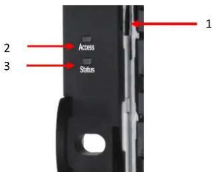
| Number | Description |
| 1 | USB port:This is designed specifically for USB LCD usage. It DOES NOT offer external USB storage function. |
| 2 | Access LED:This indicates the host interface (frontend) connectivity, not the hard drive activity.Blink: There is host interface activity (data I/O or management).OFF: There is no host interface activity. |
| 3 | Status LED:Red: System failure.Off: System OK. |

| Number | Description |
| 1 | Power button and power LED:Blue: Power ON.Off: Power OFF. |
| 2 | Reset button:Press within 2 seconds to reset the system to default settings. The default resets include: |
• Management IP Address: 192.168.0.32
- User Name: admin
• Password: 123456
USB LCD comes as an optional device for the DSN-6200/6500 Series. The standard unit doesn't include an USB LCD. Both the USB port on the front left handle and the USB port on the controller itself support the LCD function. However, the USB port doesn't support external USB storage function.

| Number | Description |
| 1 | LCD display. |
| 2 | Up button. |
| 3 | Down button. |
| 4 | ENT (Enter) button. |
| 5 | ESC (Escape) button. |
| 6 | MUTE button. |
| 7 | USB connector |
Disk Drive Assembly
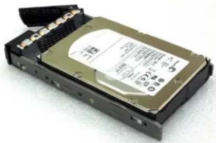
Remove a drive tray. Then install a HDD.
• To install SAS drives: align the edge of the drive to the back end of tray; the backplane can directly connect to the drives.
• To install SATA drives with 3G/6G MUX boards: align the board edge to the back end of tray; the backplane can connect the drives through the boards.
natural_image
Exterior view of a hard disk drive chassis (no visible text or labels)SAS Drive

natural_image
Exterior view of a hard disk drive chassis (no visible text or labels)SATA Drive
The front of each disk tray has four components:

This table below provides details about the front components of a disk tray.
| Number | Description |
| 1 | Power LED:Green: Drive is inserted and operational.Red: Drive failure.Off: No drive in the tray. |
| 2 | Access LED:Blue blinking: The drive is being accessed.Off: The drive is not being accessed or there is no drive in the tray. |
| 3 | Tray removal handle. |
| 4 | Latch to release the tray. |
3TB / 6G MUX Board Limitation
DSN-6200/6500 Series:
| System | JBOD | |||
| Single upgradable | Dual | Single | Dual | |
| <= 2TB SATA | No | 6G MUX board | No | 6G MUX board |
| > 2TB SATA | No | 6G MUX board | No | 6G MUX board |
| <= 2TB SAS | No | No | No | No |
| > 2TB SAS | No | No | No | No |
| HDD Type | 6G MUX Board | 3G MUX Board | ||
| SATA | 3TB | 2794 GB | 2794 GB | |
| SATA 6Gb/s | SATA 6Gb/s | SATA 3Gb/s | ||
| SATA 3Gb/s | SATA 6Gb/s | SATA 3Gb/s | ||
| SATA 1.5Gb/s | SATA 6Gb/s | SATA 1.5Gb/s | ||
| Without MUX Board | ||||
| SAS | 3TB | 2794 GB | ||
| SAS 6Gb/s | SAS 6Gb/s | |||
| SAS 3Gb/s | SAS 3Gb/s | |||
Rear View
The following example shows the DSN-6220 chassis:
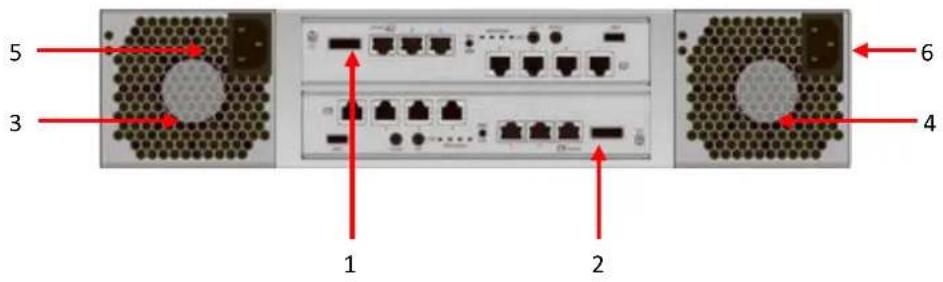
This table describes the rear modules.
| Number | Description |
| 1 | Controller 1 (CTRL 1). |
| 2 | Controller 2 (CTRL 2, only for dual-controller). |
| 3 | Fan Module (FAN1 / FAN2). |
| 4 | Fan Module (FAN3 / FAN4). |
| 5 | Power Supply Unit (PSU1). |
| 6 | Power Supply Unit (PSU2). |

This table describes the rear components.
| Number | Description |
| 1 | SAN portsDSN-6200: 6 x GbE iSCSI ports.DSN-6500: 2 x 10GbE iSCSI ports (SFP+) + 2 x GbE iSCSI ports. |
| 2 | LEDs from right to left:Controller health LED:Green: Controller status normal.Red: System booting or controller failure.Master slave LED (only for dual controllers):Green: This is the Master controller.Off: This is the Slave controller.Dirty cache LED:Orange: Data on the cache waiting to flash to disks.Off: No data on the cache.BBM LED (when status button pressed):Green: BBM installed and powered.Off: No BBM installed. |
| 3 | BBM status button (used to check the battery when the power is off.):If the BBM LED shows Green, then the BBM still has power to keep data on the cache.If the BBM LED stays Off, then the BBM power has run out and it cannot provide power for the cache anymore. It needs to be recharged or replaced. |
| 4 | Management port. |
| 5 | Console port. |
| 6 | RS 232 port for UPS. |
| 7 | SAS JBOD expansion port. |
| 8 | BBM slot. |
| 9 | USBNo function. Reserved for the future design purpose. |
| LED | 1GbE Link LED (All):Orange: Asserted when a 1G link is established and maintained.Green: Asserted when a 100M link is establish and maintained.1GbE Access LED (All):Blinking green: Asserted when the link is established and packets are being transmitted along with any receive activity.10GbE Link LED (DSN-6500):Orange: Asserted when a 1G link is established and maintained.Blue: Asserted when a 10G link is establish and maintained.10GbE Access LED (DSN-6500):Yellow: Asserted when the link is established and packets are being transmitted along with any receive activity. |

CAUTION:
Be aware that when Controller Health LED is in RED, please DO NOT unplug the controller from the system or turn off the power suddenly. This may cause unrecoverable damage, which will not be covered by warranty.
DSN-6200 (6 x GbE iSCSI) controller:

DSN-6500 (2 x 10GbE iSCSI (SFP+) + 2 x GbE iSCSI) controller:

DSN-6020 (6G SAS) JBOD controller:

RAID Concepts
RAID is the abbreviation of Redundant Array of Independent Disks. The basic idea of RAID is to combine multiple drives together to form one large logical drive. This RAID drive obtains performance, capacity and reliability than a single drive. The operating system detects the RAID drive as a single storage device.
RAID Levels
There are various RAID levels with different degrees of data protection, data availability, and performance. A description of supported RAID levels follow:
| Type | Description | Min. No. of Drives |
| RAID 0 | Disk striping. | 1 |
| RAID 1 | Disk mirroring over two disks. | 2 |
| N-way mirror | Extension to RAID 1 level. It has N copies of the disk. | N |
| RAID 3 | Striping with parity on the dedicated disk. | 3 |
| RAID 5 | Striping with interspersed parity over the member disks. | 3 |
| RAID 6 | 2-dimensional parity protection over the member disks. | 4 |
| RAID 0+1 | Mirroring of the member RAID 0 volumes. | 4 |
| RAID 10 | Striping over the member RAID 1 volumes. | 4 |
| RAID 30 | Striping over the member RAID 3 volumes. | 6 |
| RAID 50 | Striping over the member RAID 5 volumes. | 6 |
| RAID 60 | Striping over the member RAID 6 volumes. | 8 |
| JBOD | The abbreviation of Just a Bunch Of Disks. Independently address a drive. | 1 |
Volume Relationship
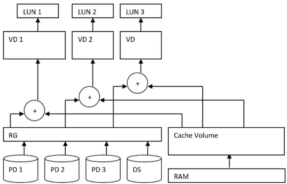
The following graphic is the volume structure which D-Link has designed. It describes the relationship of RAID components.
flowchart
graph TD
    A["LUN 1"] --> B["VD 1"]
    C["LUN 2"] --> D["VD 2"]
    E["LUN 3"] --> F["VD"]
    B --> G["+"]
    D --> H["+"]
    F --> I["+"]
    G --> J["RG"]
    H --> J
    I --> K["Cache Volume"]
    J --> L["PD 1"]
    J --> M["PD 2"]
    J --> N["PD 3"]
    J --> O["DS"]
    K --> P["RAM"]
    L --> P
    M --> P
    N --> P
    O --> P
One RG (RAID group) consists of a set of VDs (Virtual Disk) and owns one RAID level attribute. Each RG can be divided into several VDs. The VDs in one RG share the same RAID level, but may have different volume capacity. All VDs share the CV (Cache Volume) to execute the data transaction. LUN (Logical Unit Number) is a unique identifier, in which users can access through SCSI commands.
iSCSI Concepts
iSCSI (Internet SCSI) is a protocol which encapsulates SCSI (Small Computer System Interface) commands and data in TCP/IP packets for linking storage devices with servers over common IP infrastructures. iSCSI provides high performance SANs over standard IP networks like LAN, WAN or the Internet.
IP SANs are true SANs (Storage Area Networks) which allow several servers to attach to an infinite number of storage volumes by using iSCSI over TCP/IP networks. IP SANs can scale the storage capacity with any type and brand of storage system. In addition, it can be used by any type of network (Ethernet, Fast Ethernet, Gigabit Ethernet, and 10 Gigabit Ethernet) and combination of operating systems (Microsoft Windows, Linux, Solaris, Mac, etc.) within the SAN network. IP-SANs also include mechanisms for security, data replication, multi-path and high availability.

flowchart
graph TD
    A["Host 1 (initiator)"] --> B["NIC"]
    C["Host 2 (initiator)"] --> D["iSCSI HBA"]
    B <--> E["IP SAN"]
    D <--> E
    E <--> F["iSCSI device 1 (target)"]
    E <--> G["iSCSI device 2 (target)"]
Storage protocol, such as iSCSI, has “two ends” in the connection. These ends are initiator and target. In iSCSI, we call them iSCSI initiator and iSCSI target. The iSCSI initiator requests or initiates any iSCSI communication. It requests all SCSI operations like read or write. An initiator is usually located on the host side (either an iSCSI HBA or iSCSI SW initiator).
The target is the storage device itself or an appliance which controls and serves volumes or virtual volumes. The target is the device which performs SCSI command or bridge to an attached storage device.
SAS Concepts
Serial-attached SCSI offers advantages over older parallel technologies. The cables are thinner, and the connectors are less bulky. Serial data transfer allows the use of longer cables than parallel data transfer.
The target is the storage device itself or an appliance which controls and serves volumes or virtual volumes. The target is the device which performs SCSI command or bridge to an attached storage device.

flowchart
graph TD
    A["Host (initiator)"] --> B["SAS HBA"]
    B --> C["SAS device 1 (target)"]
    C --> B
Installation
2
Installation Overview
Before starting, prepare the following items:
• A management computer with a Gigabit Ethernet NIC (recommend) on the same network as the D-Link storage system.
- Connection cables:
Use CAT 5e, or CAT 6 (recommend) network cables for the management port.
• Prepare a storage system configuration plan. The plan should include network information for the management port and iSCSI data ports. If using static IP addresses, please prepare a list of the static IP addresses, the subnet mask, and the default gateway.
- Switches
DSN-6200: Gigabit switches (recommended) or Gigabit switches with VLAN / LCAP / Trunking (optional).
DSN-6500: Gigabit switches (recommended) or 10 Gigabit switches with VLAN / LCAP / Trunking (optional).
• CHAP security information, including CHAP username and password (optional).
- For dual-controller systems, it is recommended that the host logon to the target twice (both Controller 1 and Controller 2), and then the MPIO should setup automatically.
- For an iSCSI dual-controller system, install an iSNS server on the same storage area network (recommended).
Drive Slot Numbering
The drives can be installed into any slot in the enclosure. Slot numbering is reflected in Web UI.
2U12:
| Slot 1 | Slot 4 | Slot 7 | Slot 10 |
| Slot 2 | Slot 5 | Slot 8 | Slot 11 |
| Slot 3 | Slot 6 | Slot 9 | Slot 12 |

TIP:
Install at least one drive in Slot 1 to 4 (marked gray slots). System event logs are saved in these drives. Otherwise, event logs no longer exist after a reboot.
System Installation and Deployment
Using the following instructions to install and deploy the storage system.
Install BBM (Battery Backup Module). The BBM module is located inside the right PSU (PSU2 module). Release the PSU2 latch and move to the back side.
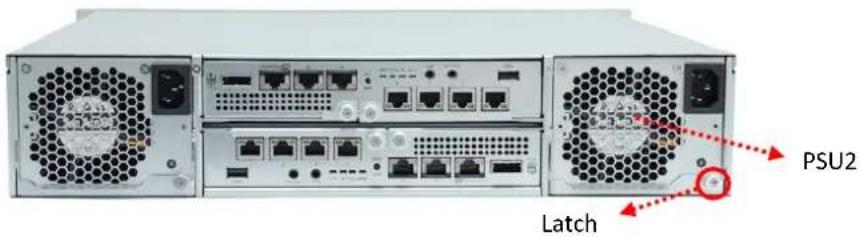
Release the screws. Connect the BBM into the PSU.

CAUTION:
Please do not touch the connector pins of the PSU when the BBM is connected.

natural_image
Exterior view of a computer drive chassis with red arrows indicating motion or force (no text or symbols)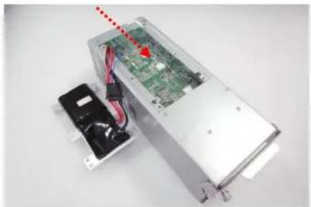
natural_image
Interior view of an electronic device showing a circuit board with exposed components and wiring, no visible text or symbols.Replace the cover on the PSU, and secure the bracket with screws.

natural_image
Exterior view of a silver computer drive chassis (no visible text or labels)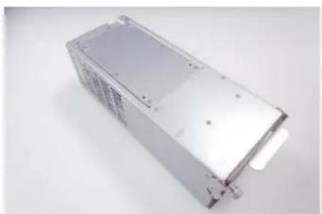
natural_image
Exterior view of a silver rectangular electronic device (no visible text or symbols)Plug it into the chassis.
• Install the Disk Drives.
Connect the management port cable and data port cables per the network plan, the topology examples for this are below.
DSN-6200 series (DSN-6220):
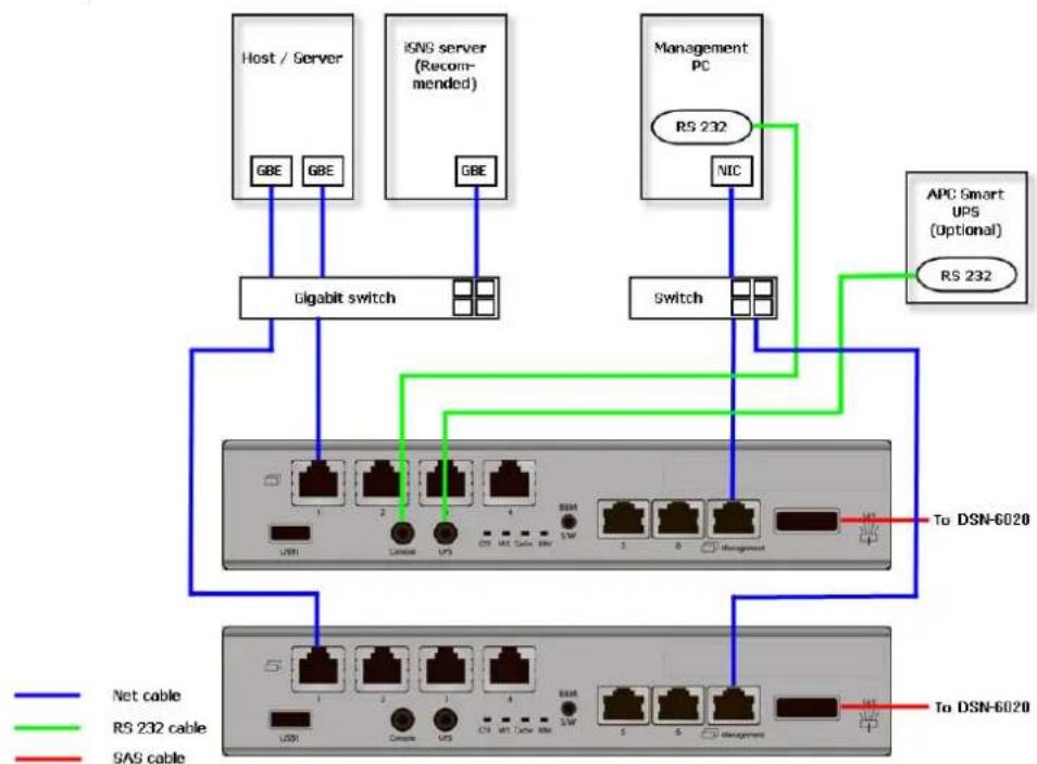
flowchart
graph TD
    A["Host / Server"] -->|GBE| B["Gigabit switch"]
    C["ISNS server (Recommended)"] -->|GBE| B
    D["Management PC"] -->|RS 232| E["Switch"]
    F["APC Smart UPS (Optional)"] -->|RS 232| E
    B --> G["Network Port 1-5"]
    E --> H["Network Port 6-10"]
    G --> I["To DSN-6020"]
    H --> J["To DSN-6020"]
    style A fill:#f9f,stroke:#333
    style C fill:#f9f,stroke:#333
    style D fill:#f9f,stroke:#333
    style F fill:#f9f,stroke:#333
    style G fill:#ccf,stroke:#333
    style H fill:#ccf,stroke:#333
    style I fill:#dfd,stroke:#333
    style J fill:#dfd,stroke:#333
DSN-6500 series (DSN-6520):

flowchart
graph TD
    A["Host / Server"] -->|10G 10G| B["10 GBE switch"]
    C["iNVS server (Recommended)"] -->|10G| B
    D["Management PC"] -->|NIC| E["Switch"]
    F["APC Smart UPS (Optional)"] -->|RS 232| E
    B --> G["USB"]
    B --> H["PCI"]
    B --> I["ACOS"]
    E --> J["To DSN-6020"]
    E --> K["To DSN-6020"]
    G --> L["USB"]
    G --> M["PCI"]
    H --> N["ACOS"]
    I --> O["ACOS"]
    J --> P["1"]
    K --> Q["2"]
    L --> R["Net cable"]
    M --> S["RS 232 cable"]
    N --> T["SAS cable"]
    O --> U["FC cable"]
JBOD DSN-6020:
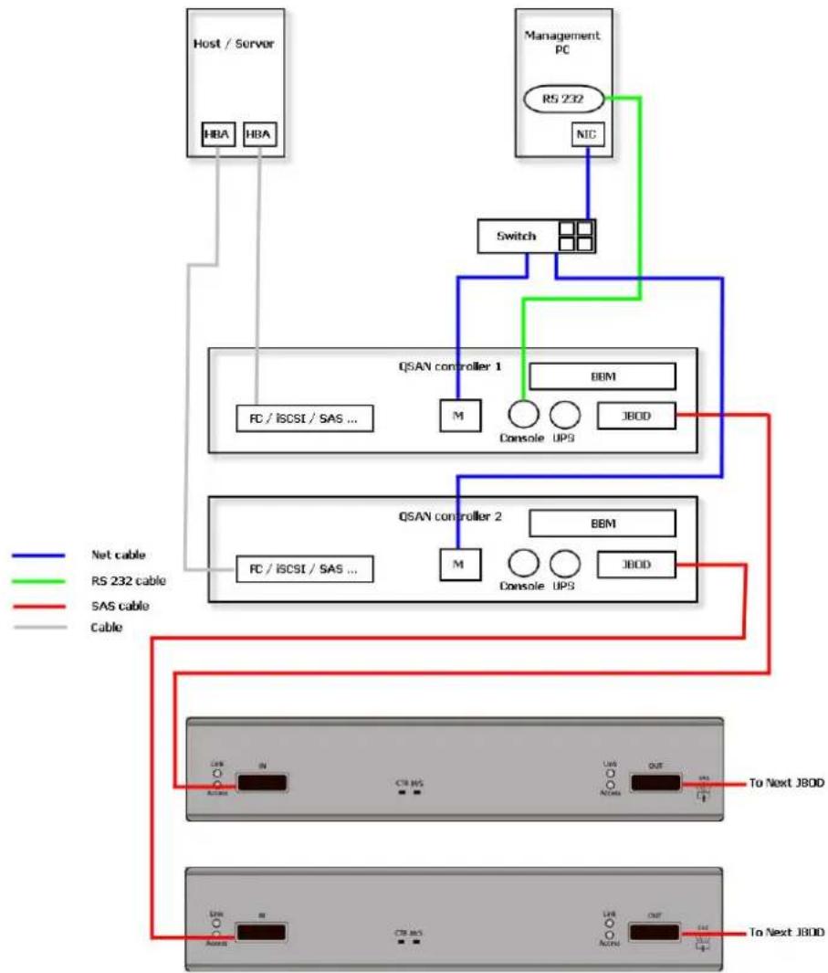
flowchart
graph TD
    A["Host / Server"] --> B["HBA"]
    A --> C["HBA"]
    D["Management PC"] --> E["R5 232"]
    E --> F["NIC"]
    F --> G["Switch"]
    G --> H["QSAN controller 1"]
    H --> I["FC / ISCSI / SAS ..."]
    H --> J["BBM"]
    H --> K["JBOD"]
    L["QSAN controller 2"] --> M["FC / ISCSI / SAS ..."]
    L --> N["BBM"]
    L --> O["JBOD"]
    P["Net cable"] --> Q["To Next JBOD"]
    R["R5 232 cable"] --> S["To Next JBOD"]
    T["SAS cable"] --> U["To Next JBOD"]
    V["Cable"] --> W["Line to Next JBOOD"]
    X["Line to Next JBOOD"] --> Y["Line to Next JBOOD"]
Dual controller topology:
For better data service availability, all the connections among hosts, switches, and the dual controllers are recommended to be redundant as shown below.

flowchart
graph TD
    A["Host / Server"] -->|GBE| B["Gigabit switch"]
    C["Host / Server"] -->|GBE| B
    B --> D["controller 1"]
    B --> E["controller 2"]
    F["Clustering"] -.-> A
    F -.-> C
    style A fill:#f9f,stroke:#333
    style C fill:#f9f,stroke:#333
    style B fill:#ccf,stroke:#333
    style D fill:#cfc,stroke:#333
    style E fill:#cfc,stroke:#333
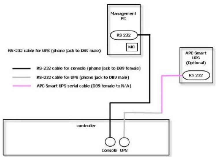
Console and UPS topology:
Connect the console cable and UPS per the following.
flowchart
graph TD
    A["Management PC\nRS 232\nMIC"] --> B["APC Smart UPS (Optional)\nRS 232"]
    C["RS-232 cable for UPS (phone jack to DB9 male)"] --> D["RS-232 cable for console (phone jack to DB9 female)"]
    E["RS-232 cable for UPS (phone jack to DB9 male)"] --> F["RS-232 cable for UPS (phone jack to DB9 male)"]
    G["APC Smart UPS serial cable (D09 female to N/A)"] --> H["APC Smart UPS (Optional)\nRS 232"]
    I["controller"] --> J["Console UPS"]
    K["Controller"] --> L["RS-232 cable for UPS (phone jack to DB9 male)"]
Using RS-232 cable for console (back color, phone jack to DB9 female), to connect from controller to management PC directly.
Using RS-232 cable for UPS (gray color, phone jack to DB9 male), to connect from controller to APC Smart UPS serial cable (DB9 female side), and then connect the serial cable to APC Smart UPS.

CAUTION: It may not work when connecting the RS-232 cable for UPS (gray color, phone jack to DB9 male) to APC Smart UPS directly.
Attach the power cords and power on the system, and then power on the hosts and the iSNS server (optional for iSCSI environment).
- Start the configuration.
Power ON / OFF
Power on the System
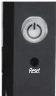
The power button is located at the right front handle. To turn on the system, you may press the power button once. After you turn the power ON, the system performs a booting process which takes a few minutes.

CAUTION:
Be aware that when Controller Health LED is in RED, please DO NOT unplug the controller from the system or turn off the power suddenly. This may cause unrecoverable damage, which will not be covered by warranty.
Power off the System
If it becomes necessary to power down the system, it is recommended using a normal, controlled shutdown form through either the LCD or Web UI to ensure all data is flushed from the cache first.
1. Shutdown using LCD:
On the LCD:
• Power off the system using a normal shutdown.
Press ENT button.
Press ▼ (down) twice to show Reboot/Shutdown, and press ENT button.
Press ▼ (down) once to show Shutdown, and press ENT button.
Press ▲ (up) once to highlight Yes, and press ENT button.
- System shutdown begins. When shutdown process completes, the power LED will turn off.
2. Shutdown using Web UI:
Using the Web UI:
- Select System Maintenance -> Reboot and Shutdown.
- Click the Shutdown icon.
- System shutdown begins. When shutdown process completes, the power LED will turn off.
3. Shutdown using Power button:
The power button is located by the right front handle.
- Forced shutdown: press and hold for more than 4 seconds. The power will be cut off immediately.
- Graceful shutdown: press once to initialize graceful shutdown. Press a second time within 4 seconds to confirm and start graceful shutdown. If there is no 2nd press within 4 seconds, disable graceful shutdown and return to normal operating mode.
Quick Setup
3
Management Interfaces
There are several management methods to manage the storage system, described on the following pages.
Serial Console
Use console cable (NULL modem cable) to connect the console port of the storage system to RS 232 port of the management PC. The console settings are on the following:
• Baud rate: 115200, 8 data bit, no parity, 1 stop bit, and no flow control.
• Terminal Type: vt100
The initial defaults for administrator login are:
- User Name: admin
• Password: 123456
Secure Shell Remote Access
SSH (secure shell) software is required for remote login. The SSH client software is available on the following web sites:
• SSH Tectia Client: http://www.ssh.com/
• PuTTY: http://www.chiark.greenend.org.uk/
The default management IP address is 192.168.0.32/255.255.255.0, please configure your computer IP address at the same subnet of the system (e.g.: 192.168.1.234/255.255.255.0). The remote control settings are on the following:
• Host IP:
- User Name: admin
- Password: 123456

TIP:
D-Link systems support SSH for remote access only. When using SSH, the IP address and password are required for login.
LCD
After booting up the system, the following screen shows management port IP and model name.
For example:
192.168.008.174
D-Link DSN-6500
To access the LCD options, use the ENT (Enter) button, ESC (Escape) button, ▲ (up) and ▼ (down) to scroll through the functions.
This table describes the function of each item.
| Function | Description |
| System Info. | Display system information including firmware version and amount of RAM. |
| Alarm Mute | Mutes an alarm after an error occurs. |
| Reset/Shutdown | Reset or shutdown the system. |
| Quick Install | Provide quick steps to create a volume. |
| Volume Wizard | Provide smart steps to create a volume. |
| View IP Setting | Display current IP address, subnet mask, and gateway. |
| Change IP config | Set IP address, subnet mask, and gateway. There are 2 options: DHCP (Get IP address from DHCP server) or static IP. |
| Enc. Management | Shows the enclosure data for physical disk temperatures, fan status, and power supply status. |
| Reset to Default | Reset the system to default settings. The default resets include:Management IP Address: 192.168.0.32User Name: adminPassword: 123456 |
WARNING or ERROR events displayed on the LCD are automatically filtered by the LCD default filter. The filter setting can be changed in the Web UI under System Configuration -> Log and Alert Settings.
This table displays the LCD menu hierarchy.
| Main | L1 | L2 | L3 | L4 | L5 |
| System Info. | Firmware Version | ||||
| RAM SizeMB | |||||
| Alarm Mute | ▲Yes No▼ | ||||
| Reset/Shutdown | Reset | ▲YesNo▼ | |||
| Shutdown | ▲YesNo▼ | ||||
| Quick Install(only availableif not alreadyset) | Apply TheConfig | ▲YesNo▼ | |||
| naa0+1> | |||||
| nnn GB | |||||
| VolumeWizard(only availableif not alreadyset) | Local | ||||
| RAID 0 | Use defaultalgorithm | Volume SizeGB | Apply TheConfig▲Yes No▼ | ||
| RAID 1 | |||||
| RAID 3 | |||||
| RAID 5 | |||||
| RAID 6 | |||||
| RAID 0+1> | |||||
| JBOD ▲▼ | |||||
| RAID 0 | New n disk▲▼GB | AdjustVolume Size | Apply TheConfig▲Yes No▼ | ||
| RAID 1 | |||||
| RAID 3 | |||||
| RAID 5 | |||||
| RAID 6 | |||||
| RAID 0+1> | |||||
| View IPSetting | IP Config | ||||
| DHCP / BOOTP> | |||||
| IP Address<192.168.001.234> | |||||
| IP Subnet Mask<255.255.255.0> | |||||
| IP Gateway | |||||
| Change IPConfig | DHCP | ▲YesNo▼ | |||
| BOOTP | ▲YesNo▼ | ||||
| Static IP | IP Address | Adjust IPaddress | |||
| IP SubnetMask | AdjustSubmask IP | ||||
| IP Gateway | AdjustGateway IP |
| Apply IP Setting | ▲Yes No▼ | ||
| Enc. Management | Phy. Disk Temp. | Local Slot(C) | |
| Cooling | Local FAN: | ||
| RPM | |||
| Power Supply | Local PSU: | ||
| Reset to Default | ▲Yes No▼ |
The USB LCD was developed to add more mobility and flexibility during deployment and installation. In order to save costs, several DSN-6200/6500 systems can share one USB LCD. All the functions provided by USB LCD are the same as the original LCD introduced in the previous section. Please be aware to remove the USB LCD before adding the front bezel.


CAUTION:
To prevent data loss, when powering down the storage system, it is recommended to execute Reset/Shutdown -> Shutdown -> Yes to flush the data from the cache to the physical disks.
Web UI
D-Link storage systems support graphic user interface operation. They support most common web browsers. Be sure to connect the LAN cable to the management port of the system.
The default management IP address is 192.168.0.32/255.255.255.0, please configure your computer IP address at the same subnet of the system (e.g.: 192.168.1.234/255.255.255.0). And then enter the IP address into your browser to display the authentication screen.
- http://

To access the Web UI, you have to enter a user name and password. The initial defaults for administrator login are:
- User Name: admin
- Password: 123456

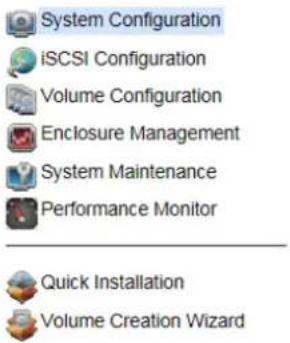
Choose the functions from the Menu Bar on the left side of the window to make any configuration changes.

TIP:
The Host Port Configuration menu bar option is only visible when the controller has multiple interfaces. The iSCSI Configuration menu bar option is only visible when the controller has iSCSI ports.
There are up to seven indicators and three icons at the top-right corner. The last indicator (Dual controller) is only visible when two controllers are installed.

natural_image
Row of seven icons including database, battery, recycling symbol, and lightning bolt on blue background (no text or labels)| Icon | Description | |
 |  | RAID indicator:Green: All RAID groups are functioning.Red: A RAID group is degraded or has failed. |
 |  | Temperature indicator:Green: Temperature is normal.Red: Temperature is too high. |
 |  | Voltage indicator:Green: Voltage values are normal.Red: Voltage values are out of range. |
 |  | UPS indicator:Green: UPS is functioning or no UPS is connected.Red: UPS connection has failed. |
 |  | Fan indicator:Green: Fan is working well.Red: Fan failed. |
 |  | Power indicator:Green: Power supplies are connected and working well.Red: A power supply has failed or is no longer connected. |
 |  | Dual controller indicator:Green: Dual controllers are active and working well-orange: One of the dual controllers has failed. |
| Return to home page. | ||
| Logout of the management web UI. | ||
| Mute alarm beeper. | ||

This table describes the indicators and icons.
TIP:
If the status indicators in Internet Explorer (IE) are displayed in gray, not in blinking red, please enable Tools -> Internet Options -> Advanced -> Play animations in webpages options in IE. The default value is enabled, but some applications disable it.
How to Use the Guided Configurations
To help users get started quickly, two guided configuration tools are available in the Web UI and LCD. Quick Installation gives you an easy way to create a volume. Volume Creation Wizard provides a smarter policy to help users to create a volume. If you are an advanced user, you can skip these steps.
Quick Installation Tool
This tool guides you through the process of setting up basic array information, configuring network settings, and the creation of a volume on the storage system. Please make sure that you have some free hard drives installed on the system. SAS drivers are recommended.
| Physical Disks | RAID Groups | Virtual Disks | Snapshots | Logical Units | Replications | |||||||||
| Show disk for: - Local - Show disk size in: GB | ||||||||||||||
| Slot | Size (GB) | RAID Group | RAID Set | Virtual Disk | Status | Health | Usage | Vendor | Serial Number | Rate | Write Cache | Standby | Read-Ahead | Command Queuing |
| 1 | 3725 | r1 | N/A | N/A | Online | Good | RAID | WD | VMC1F0086939 | SAS 6.0Gb/s | Disabled | Disabled | Enabled | Enabled |
| 2 | 3725 | r1 | N/A | N/A | Online | Good | RAID | WD | VMC1F0086938 | SAS 6.0Gb/s | Disabled | Disabled | Enabled | Enabled |
| 3 | 3725 | r1 | N/A | N/A | Online | Good | RAID | WD | VMC1F0108997 | SAS 6.0Gb/s | Disabled | Disabled | Enabled | Enabled |
| 4 | 3725 | r1 | N/A | N/A | Online | Good | RAID | WD | VMC1F0086703 | SAS 6.0Gb/s | Disabled | Disabled | Enabled | Enabled |
| 5 | 3725 | r1 | N/A | N/A | Online | Good | RAID | WD | VMC1F0088364 | SAS 6.0Gb/s | Disabled | Disabled | Enabled | Enabled |
| 6 | 3725 | r1 | N/A | N/A | Online | Good | RAID | WD | VMC1F0087264 | SAS 6.0Gb/s | Disabled | Disabled | Enabled | Enabled |
| 7 | 3725 | r1 | N/A | N/A | Online | Good | RAID | WD | VMC1F0109198 | SAS 6.0Gb/s | Disabled | Disabled | Enabled | Enabled |
- Click Quick Installation from the menu bar.
- Enter a System Name and set up the Date and Time. Click the Next button to proceed.

- Confirm or change the management port IP address and DNS server. If the default HTTP, HTTPS, and SSH port numbers are not allowed on your network, they can be changed here as well.
Quick Installation
Step 2: Network Settings
MAC Address
MAC Address:
00:13:78:BB:38:80
Address
○ Use DHCP
○ Use BOOTP
- Specify a Static IP Address
IP Address:
192.168.1.234
Subnet Mask:
255.255.0.0
Gateway:
DNS Server Address
Address:
Service Ports
HTTP Port:
80
HTTPS Port:
443
SSH Port:
22
<< Back
Next >>
Cancel
- For iSCSI Configurations, use this step to set up the data port iSCSI IP address, and then click the Next button.
Quick Installation
Step 3: iSCSI IP Address Settings
LAN1:
Use DHCP
- Specify a Static IP Address
Address:
10.0.0.1
Mask:
255.255.255.0
Gateway:
10.0.0.254
<< Back
Next >>
Cancel
- Choose a RAID Level. The number in the brackets is the maximum capacity at the RAID level. This step utilizes all drives in the storage system as well as any JBOD expansion arrays present. This option allows the selection of the RAID type and the number of drives in each array.
Quick Installation
Step 4: Volume Settings
Enclosure:
Local
RAID Level:

<< Back
Next >>
Cancel
- Verify all items, and then click the Finish button to complete the quick installation.
Quick Installation
Step 1: System Settings

The iSCSI information is only displayed when iSCSI controllers are used. Use the Back button to return to a previous page to change any setting.
Volume Creation Wizard
The Volume Creation Wizard provides a smarter policy to determine all possibilities and volume sizes in the different RAID levels that can be created using the existing free drives. It provides:
• Largest capacity for each RAID level from which to choose.
• The fewest number of drives for each RAID level / volume size.
This way, after choosing a RAID level, you may find that some drives are still available (free status). This phenomenon is the result of using smart design. For example, a user chooses the RAID 5 level and the system has 12200GB + 480GB free drives inserted. Generally, if using all 16 drives for a RAID 5 group, the maximum size of volume is (16-1)80GB = 1200GB . This wizard provides a smarter check and searches the most efficient way of using free drives. It uses 200GB drives only to provide (12-1)200GB = 2200GB capacity, as a result the volume size is larger using less drives.
- Click Volume Creation Wizard from the menu bar.
- Choose a RAID Level. The number in the brackets is the maximum capacity at the RAID level.

- Select the default option Maximize the size of the RAID group or manual option Select the number of disks to use. From the drop-down list, select either the RAID Group capacity combination desired. Click Next button to proceed.

- Enter the Volume Size (GB) desired that is less than or equal to the default available size shown. Then click Next button.

- Use LBA 64 support? It depends on the operation system.

- Finally, verify the selections and click Finish button if they are correct.
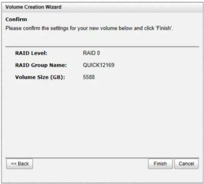
The volume is created and named by the system automatically. It is available to use now.
Basic Configuration
4
Interface Hierarchy
This table describes the hierarchy of the web GUI.
| Menu Bar | L1 | L2, Button or Menu |
| System Configuration | System Settings | System Name / Date and Time / System Indication |
| Network Settings | MAC Address / IP Address / DNS Server Address / Service Ports | |
| Login Settings | Login Options / Admin Password / User Password | |
| Email Notification Settings | Email Settings / Send Test Mail | |
| Log and Alert Settings | SNMP Trap Settings / Windows Messenger / Syslog Server Settings / Admin Interface and Front Display Alerts / Device Buzzer | |
| iSCSI Configuration (This option is only visible when the controller has iSCSI ports.) | Network Setup | Show information for: <Controller 1| Controller 2>Options: [iSCSI Bonding Settings| Delete iSCSI Bonding] / Set VLAN ID / iSCSI IP Address Settings / Make Default Gateway / [Enable| Disable] Jumbo Frames / Ping Host / Reset Port |
| Entity and iSNS Settings | Entity Name / iSNS IP Address | |
| Host Configuration (This option is only visible when the controller has multiple interfaces.) | iSCSI Node | Show information for: <Controller 1| Controller 2>Options: Authentication Method / Change Portal / Rename Alias / Users |
| Active Sessions | Show information for: <Controller 1| Controller 2>Connection Details / Disconnect | |
| CHAP Accounts | Create UserOptions: Modify User Information / Delete User | |
| Volume Configuration | Physical Disks | Show disk for: <-Local-| -JBODn->Show disk size in: <(GB) | (MB)>Disk Health Check / Disk Check ReportOptions: Set Free Disk / Set Global Spare / Set Local Spare / Set Dedicated Spare / Upgrade / Disk Scrub / Read Error Cleared / Turn [on| off] the Indication LED / More information |
| RAID Groups | Show RAID size in: <(GB) | (MB)>Create | |
| Options: Migrate RAID Level / Move RAID Level / Activate / Deactivate / Verify Parity / Delete / Change Preferred Controller / Change RAID Options / Add RAID Set / Add Policy / More informationRAID Set options: Remove / Move RAID Level / List DisksRAID Group Policy options: Delete / Modify | ||
| Virtual Disks | Create / Cloning OptionsOptions: Extend / Set SSD Caching / Verify Parity / Delete / Set Properties / Space Reclamation / Attach LUN / Detach LUNs / List LUNs / Set Clone / Set Snapshot Space / Cleanup Snapshots / Take a Snapshot / Scheduled Snapshots / List Snapshots / More information | |
| Snapshots | Set Snapshot Space / Scheduled Snapshots / Take a Snapshot / Cleanup SnapshotsOptions: Set Quota / Rollback / Delete | |
| Logical Units | Attach LUNOptions: Detach LUN | |
| Replication | Create / Rebuild / Replication Options / Shaping Setting ConfigurationOptions: Start / Stop / Set Task Shaping / Add Path / Delete Path / Schedule / Delete / Add Connection / Delete Connection | |
| Enclosure Management | Hardware Monitor | Show information for: < -Local- | -JBODn->Temperature (Internal)/(Case): < (C) / (F) >Controller 1 Monitors / Controller 2 Monitors / BackplaneOptions: Auto Shutdown |
| UPS | UPS Type / Shutdown Battery Level (%) / Shutdown Delay (Seconds) / Shutdown UPS / UPS Status / UPS Battery Level | |
| SES | [Enable | Disable] | |
| S.M.A.R.T. | Show information for: < -Local- | -JBODn->Temperature (Internal)/(Case): < (C) / (F) > | |
| System Maintenance | System information | Download System Information |
| Event log | Event Log Level to Show: < Information | Warning | Error >Download / Mute Buzzer / Clear | |
| Upgrade | Controller Module Firmware Update / JBOD Firmware Update / Controller Mode | |
| Firmware Synchronization (This option is only visible when dual controllers are inserted.) | Apply | |
| Reset to Factory Default | Reset | |
| Configuration Backup | Import or Export / Import File | |
| Volume Restoration | Options: Restore | |
| Reboot and Shutdown | Reboot / ShutdownReboot options: Both Controller 1 and Controller 2 /Controller 1 / Controller 2 | |
| Performance Monitor | Disk | Show disk for: < -Local- | -JBODn-> |
| iSCSI | Controller 1 / Controller 2 | |
| Quick Installation | Step 1 / Step 2 / Step 3 / Step 4 / Confirm | |
| Volume Creation Wizard | Step 1 / Step 2 / Step 3 / Confirm |
System Configuration
The System Configuration menu option is for accessing the System Settings, Network Settings, Login Settings, Email Notification Settings, and Log and Alert Settings option tabs.
System Settings
Network Settings
Login Settings
Email Notification Settings
Log and Alert Settings
System Settings
The System Settings tab is used to setup the system name and date.

The options available on this tab are:
• System Name: Change the System Name, highlight the old name and type in a new one.
- Date and Time: To change the current date, time and time zone settings, check Change Date and Time. The changes can be done manually or synchronized from an NTP (Network Time Protocol) server.
- System Identification: To Flash the status light on the front display for locating this system in the racks, click OK button. To stop Flash the status light on the front display, click the OK button again.
When it is done, click the Apply button.
Network Settings
The Network Settings tab is used to view the MAC address and change basic network settings.
Change Network Settings
On this screen change the network settings for the administration port.

Enable dual management ports
MAC Address
MAC Address:
00:13:78:BB:38:80
IP Address
○ Use DHCP
○ Use BOOTP
- Specify a Static IP Address
IP Address:
192.168.1.234
Subnet Mask:
255.255.0.0
Gateway:
192.168.1.254
DNS Server Address
Address:
8.8.8.8
Service Ports
HTTP Port:
80
HTTPS Port:
443
SSH Port:
22
Apply
The options available on this tab are:
- Enable dual management ports: This is for dual controller models. Check it to enable dual management ports.
• MAC Address: Display the MAC address of the management port in the system.
• IP Address: The option can change IP address for remote administration usage. There are three options: DHCP, BOOTP, and Specify a Static IP Address. The default setting is DHCP.
• DNS Server Address: If necessary, the IP address of DNS server can be entered or changed here.
• Service Ports: If the default port numbers of HTTP, HTTPS, and SSH are not allowed on the network, they can be changed here.
When it is done, click the Apply button.
Login Settings
The Login Settings tab is used to control access to the storage system. For security reasons, set the auto logout option or set the limit access to one administrator at a time. The other options can change the Admin and User passwords.
Change Login Options and Passwords
When the auto logout option is enabled, you will be logged out of the admin interface after the time specified. The login lock option prevents multiple people from administering the storage server at the same time.
Login Options
Auto Logout:
Login Lock:
Disable

Disable -
Enable
Admin Password
□ Change Admin Password
Current Password:
New Password:
Re-type New Password:
User Password
□ Change User Password
New Password:
Re-type New Password:
Apply
The options available on this tab are:
• Auto Logout: When the auto logout option is enabled, you will be logged out of the admin interface after the time specified. The options available are: Disable (default), 5 minutes, 30 minutes and 1 hour options.
- Login Lock: When the login lock is enabled, the system allows only one user to login to the web UI at a time. There are Disable (default) and Enable options.
- Change Admin Password: Check it to change administrator password. The maximum length of password is 12 alphanumeric characters.
- Change User Password: Check it to change user password. The maximum length of password is 12 alphanumeric characters.
When it is done, click the Apply button.
Email Notification Settings
The Email Notification Settings tab is used to enter up to three email addresses for receiving the event notifications. Fill in the necessary fields and click Send Test Email button to test whether it is available. Some email servers will check the mail-from address and need the SMTP relay settings for authentication.

TIP:
Please make sure the DNS server IP is well-setup in System Configuration -> Network Settings. So the event notification emails can be sent successfully.
You can also select which levels of event logs that you would like to receive. The default setting only includes Warning and Error event logs.
Configure Email Notification Settings
You can specify up to three email addresses for email notifications. You should use the SMTP server option to specify a specific email server that you would like to use for sending email notifications (required if your network will not allow this device to send the email directly).
After the information is set, you can click 'Send test mail' to test whether email functions are available.

When it is done, click the Apply button.
Log and Alert Settings
The Log and Alert Settings tab is used to setup SNMP traps (for alerting via SNMP), pop-up messages via Windows messenger (not MSN or Skype), alerts via the syslog protocol, the pop-up alerts, and alerts on the front display. The device buzzer is also managed here.
SNMP Trap Settings
Host Address #1:
Host Address #2:
Host Address #3:
Community:
SNMP MIB File Download:
Alert Levels To Send:
public
Download
Information Warning Error
Windows Messenger
Host Address #1:
Host Address #2:
Host Address #3:
Alert Levels To Send:
□ Information √ Warning √ Error
Syslog Server Settings
Host Address or Name:
UDP Port:
Facility:
Alert Levels To Log:
514
User
□ Information ☑ Warning ☑ Error
Admin Interface and Front Display Alerts
Admin Interface Popup Alerts:
Alerts to Show on Front Display:
□ Information □ Warning □ Error
□ Information √ Warning √ Error
Device Buzzer
Disable the Device Buzzer:
Apply
The options available on this tab are:
- SNMP Trap Settings: It allows up to three SNMP trap addresses. The default community setting is public. You can check the alert levels that you would like to receive. The default setting only includes Warning and Error event logs. If necessary, click Download to get the MIB file for importing to the SNMP client tool.
There are many SNMP tools available on the internet.
SNMPc: http://www.snmpc.com/
Net-SNMP: http://net-snmp.sourceforge.net/
- Windows Messenger: You must enable the Messenger service in Windows (Start -> Control Panel -> Administrative Tools -> Services -> Messenger). It allows up to three host addresses. You can also check the alert levels for receiving emails here.
- System Server Settings: Fill in the host address and the facility for syslog service. The default UDP port is 514. You can also check the alert levels here.
There are some syslog server tools available on the internet for Windows.
WinSyslog: http://www.winsyslog.com/
Kiwi Syslog Daemon: http://www.kiwisyslog.com/
Most UNIX systems build in syslog daemon.
- Admin Interface and Front Display Alerts: You can check the alert level that will activate a pop-up message in the Web UI or on the front display.
• Device Buzzer: Check it to disable the device buzzer. Uncheck it to activate the device buzzer.
When it is done, click the Apply button.
Host Port / iSCSI Configuration
The Host port / iSCSI Configuration menu option is for accessing the Network Setup, Entity and iSNS Settings, iSCSI Nodes, Active Sessions, CHAP Account.
| Network Setup | Entity and iSNS Settings | iSCSI Nodes | Active Sessions | CHAP Accounts | Fibre Channel |
Network Setup
The Network Setup tab is used to change IP addresses of iSCSI data ports. The two controllers have different iSCSI ports, listed below:
DSN-6200/6500 Series:
• DSN-6200: 6 x GbE iSCSI ports per controller.
• DSN-6500: 2 x 10GbE iSCSI ports + 2 x GbE iSCSI ports per controller.
These network ports must be assigned IP addresses before they can be used. For better performance or fault tolerance reason, they can be set as Trunking or LACP. These bonding network ports share a single IP address. The following example shows the DSN-6200 Series (DSN-6210: 6 x GbE iSCSI ports).
| Name | LAG | LAG No | VLAN ID | Use DHCP | IP Address | Netmask | Gateway | Jumbo Frames | MAC Address | Link | |
| ▼ | LAN1 | No | N/A | N/A | No | 10.0.0.1 | 255.255.255.0 | 10.0.0.254 | Disabled | 00:13:78:bb 38:82 | 1 Gbps |
| ▼ | LAN2 | No | N/A | N/A | No | 10.0.0.2 | 255.255.255.0 | 10.0.0.254 | Disabled | 00:13:78:bb 38:83 | Down |
| ▼ | LAN3 | No | N/A | N/A | No | 10.0.0.3 | 255.255.255.0 | 10.0.0.254 | Disabled | 00:13:78:bb 38:84 | Down |
| ▼ | LAN4 | No | N/A | N/A | No | 10.0.0.4 | 255.255.255.0 | 10.0.0.254 | Disabled | 00:13:78:bb 38:85 | Down |
| ▼ | LAN5 | No | N/A | N/A | No | 10.0.0.5 | 255.255.255.0 | 10.0.0.254 | Disabled | 00:13:78:bb 38:86 | Down |
| ▼ | LAN6 | No | N/A | N/A | No | 10.0.0.6 | 255.255.255.0 | 10.0.0.254 | Disabled | 00:13:78:bb 38:87 | Down |
This figure shows six iSCSI data ports. These data ports are set up with a static IP address. For the other controllers, they can be set up the same way.
The options available on this tab:
- iSCSI Bonding Settings: The default mode of each iSCSI data port is for it to be individually connected without any bonding. Trunking and LACP (Link Aggregation Control Protocol) settings can be setup here. At least two iSCSI data ports must be checked for iSCSI bonding.
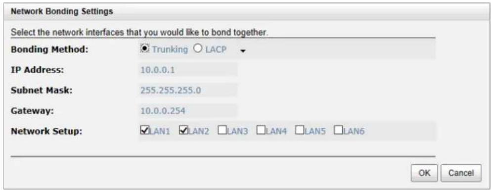
Trunking: Configures multiple iSCSI ports to be grouped together into one in order to increase the connection speed beyond the limit of a single iSCSI port.
LACP: The Link Aggregation Control Protocol is part of IEEE specification 802.3ad that allows bonding of several physical ports together to form a single logical channel. LACP allows a network switch to negotiate an automatic bundle by sending LACP packets to the peer. The advantages of LACP are that it increases bandwidth usage and it automatically performs a failover when the link status fails on a port.
- Set VLAN ID: VLAN is a logical grouping mechanism implemented on switch device. VLANs are collections of switching ports that comprise a single broadcast domain. It allows network traffic to flow more efficiently within these logical subgroups. Please consult your network switch user manual for VLAN setting instructions. Most of the work is done at the switch part. All you need to do is to make sure that your iSCSI port's VLAN ID matches that of switch port. If your network environment supports VLAN, you can use this function to change the configurations. Fill in VLAN ID and Priority settings to enable VLAN.
Set VLAN ID - LAN1
VLAN ID:
Priority:
0
VLAN ID range (2\~4094)
Priority range (0 \~ 7)
OK Cancel
VLAN ID: VLAN ID is a 12-bit number. Its range is from 2 to 4094, while 0, 1, and 4095 are reserved for special purposes.
Priority: The PCP (Priority Code Point) is a 3-bit number and reserved for QoS. The definition complies with IEEE 802.1p protocol, ranging from 0 to 7, with 0 as the default value. In normal cases, you don't need to set this value. Using the default will do just fine.

TIP:
If iSCSI ports are assigned with VLAN ID before creating aggregation takes place, aggregation will remove VLAN ID. You need to repeat the steps to set VLAN ID for the aggregation group.
- iSCSI IP Address Settings: It can assign an iSCSI IP address of the iSCSI data port. There are two options: Use DHCP to acquire an IP address automatically or Specify a Static IP Address to set the IP address manually.
iSCSI IP Address Settings
You can select 'DHCP' to acquire an IP address automatically or select 'Static' to specify an IP address manually.

Use DHCP

Specify a Static IP Address
IP Address: 10.0.0.1
Subnet Mask: 255.255.255.0
Gateway: 10.0.0.254
OK Cancel
- ▼ → Make Default Gateway: Set the gateway of the IP address as default gateway. There can be only one default gateway. To remove the default gateway, click ▼ → Remove Default Gateway.
- ▼ → Enable jumbo frames: It can enable the MTU (Maximum Transmission Unit) size. The maximum jumbo frame size is 3900 bytes. To disable jumbo frames, click ▼ → Disable Jumbo Frames.

CAUTION:
VLAN ID, jumbo frames for both the switching hub and HBA on host must be enabled. Otherwise, the LAN connection cannot work properly.
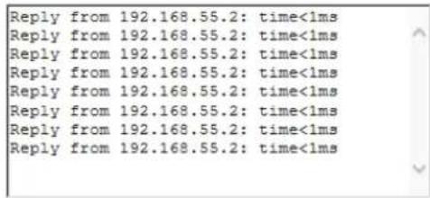
- Ping host: It can verify the port connection from a target to the corresponding host data port. Input the host's IP address and click the Start button. The system will display the ping result. Or click the Stop button to stop the test.
Please input the host's IP address:
192.168.55.2
Start
Stop
- Reset Port: If the behavior of the port is abnormal, try to reset the port to make it normal.
Entity and iSCSI Settings
The Entity and iSCSI Settings tab is used to view the entity name of the system, and setup iSNS IP for the iSNS (Internet Storage Name Service) protocol. It allows automated discovery, management and configuration of iSCSI devices on a TCP/IP network. To use iSNS, an iSNS server needs to be added to the SAN. When this is done, the iSNS server IP address must be added to the storage system for iSCSI initiator service to send queries to it.

To make changes, enter the Entity Name and the iSNS IP Address, and then click Apply.
iSCSI Nodes
The iSCSI Nodes tab is used to view the target name for iSCSI initiator. The two controllers support multiple nodes, listed below.
• DSN-6200 Series: support up to 64 multiple nodes per controller.
• DSN-6500 Series: support up to 64 multiple nodes per controller.
| ID | Auth | Node Name | Portal | Alias | |
| 0 | None | ign. 1986-06.com.d-link.dsn-6500-006919a40:dev0. ctr1 | 0 0.0.0 3260, 192.168.10.20 3260, 192.168.10.21 3260 | ||
| 1 | None | ign. 1986-06.com.d-link.dsn-6500-006919a40:dev1. ctr1 | 0 0.0.0 3260, 192.168.10.20 3260, 192.168.10.21 3260 | ||
| 2 | None | ign. 1986-06.com.d-link.dsn-6500-006919a40:dev2. ctr1 | 0 0.0.0 3260, 192.168.10.20 3260, 192.168.10.21 3260 | ||
| 3 | None | ign. 1986-06.com.d-link.dsn-6500-006919a40:dev3. ctr1 | 0 0.0.0 3260, 192.168.10.20 3260, 192.168.10.21 3260 | ||
| 4 | None | ign. 1986-06.com.d-link.dsn-6500-006919a40:dev4. ctr1 | 0 0.0.0 3260, 192.168.10.20 3260, 192.168.10.21 3260 | ||
| 5 | None | ign. 1986-06.com.d-link.dsn-6500-006919a40:dev5. ctr1 | 0 0.0.0 3260, 192.168.10.20 3260, 192.168.10.21 3260 | ||
| 6 | None | ign. 1986-06.com.d-link.dsn-6500-006919a40:dev6. ctr1 | 0 0.0.0 3260, 192.168.10.20 3260, 192.168.10.21 3260 | ||
| 7 | None | ign. 1986-06.com.d-link.dsn-6500-006919a40:dev7. ctr1 | 0 0.0.0 3260, 192.168.10.20 3260, 192.168.10.21 3260 | ||
| 8 | None | ign. 1986-06.com.d-link.dsn-6500-006919a40:dev8. ctr1 | 0 0.0.0 3260, 192.168.10.20 3260, 192.168.10.21 3260 | ||
| 9 | None | ign. 1986-06.com.d-link.dsn-6500-006919a40:dev9. ctr1 | 0 0.0.0 3260, 192.168.10.20 3260, 192.168.10.21 3260 | ||
| 10 | None | ign. 1986-06.com.d-link.dsn-6500-006919a40:dev10.ctr1 | 0 0.0.0 3260, 192.168.10.20 326O, 192.168.10.21 326O | ||
| 11 | None | ign. 1986-06.com.d-link.dsn-650O-006919a4O:dev1I.Ctr1 | O_W . O_W . O_W . O_W . O_W . O_W . O_W . O_W . O_W . O_ . O_W . O_W . O_W . O_W . O_W . O_W . O_W . O_W . ( ) |
The options available on this tab are:
- Authentication Method: CHAP (Challenge Handshake Authentication Protocol) is a strong authentication method used for user login. It's a type of authentication in which the authentication server sends the client a key to be used for encrypting the username and password. CHAP enables the username and password to transmit in an encrypted form for protection.

TIP:
A CHAP account must be added before you can use this authentication method. Please refer to CHAP Accounts section to create an account if none exists.
To use CHAP authentication, please follow the procedures.
Select one of the nodes from one controller.
Check ▼ → Authentication Method.
Select CHAP from the drop-down list.

Click the OK button.
| ID | Auth | Node Name | Portal | Alias | |
| ▼ | 0 | CHAP | iqn.1986-06.com.d-link:dsn-6500-006919a40:dev0.ctr1 | 0.0.0.0:3260, 192.168.10.20:3260, 192.168.10.21:3260 | |
| ▼ | 1 | CHAP | iqn.1986-06.com.d-link:dsn-6500-006919a40:dev1.ctr1 | 0.0.0.0:3260, 192.168.10.20:3260, 192.168.10.21:3260 | |
| ▼ | 2 | None | iqn.1986-06.com.d-link:dsn-6500-006919a40:dev2.ctr1 | 0.0.0.0:3260, 192.168.10.20:3260, 192.168.10.21:3260 | |
| ▼ | 3 | None | iqn.1986-06.com.d-link:dsn-6500-006919a40:dev3.ctr1 | 0.0.0.0:3260, 192.168.10.20:3260, 192.168.10.21:3260 | |
| ▼ | 4 | None | iqn.1986-06.com.d-link:dsn-6500-006919a40:dev4.ctr1 | 0.0.0.0:3260, 192.168.10.20:3260, 192.168.10.21:3260 |
Check ▼ → User.
Select the CHAP user(s) that will have access to the node. It can be more than one, but there must be at least one user to enable chap protection on the node.
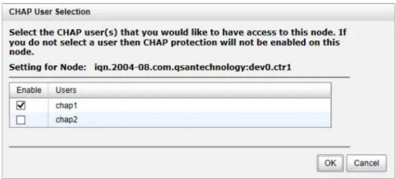
Click the OK button.
To disable CHAP authentication, please follow the procedure below.
Select the node on which you want to disable CHAP.
Check ▼ → Authentication Method.
Change it to None from the drop-down list.
Click the OK button.
- ▼ → Change Portal: Use this iSCSI node option to change the network ports available.
Select one of the nodes from one controller.
Check ▼ → Change Portal.
Select the network ports that you would like to be available for this iSCSI node.
Change Network Portal
Assign or Change LAN Portal
Select the network ports that you would like to be available for this iSCSI node.
Available On:
☑10.0.0.1:3260 (LAN 1, Use DHCP: No, Jumbo Frames: Disabled)
☑10.0.0.2:3260 (LAN 2, Use DHCP: No, Jumbo Frames: Disabled)
☑10.0.0.3:3260 (LAN 3, Use DHCP: No, Jumbo Frames: Disabled)
☑10.0.0.4:3260 (LAN 4, Use DHCP: No, Jumbo Frames: Disabled)
☑10.0.0.5:3260 (LAN 5, Use DHCP: No, Jumbo Frames: Disabled)
☑10.0.0.6:3260 (LAN 6, Use DHCP: No, Jumbo Frames: Disabled)
OK
Cancel
Click OK button.
- Rename Alias: Use this option to add or change iSCSI alias.
Select one of the nodes from one controller.
Check ▼ → Rename Alias.
Enter the Alias Name. Leave it empty to remove the alias.
Click the OK button.
iSCSI Alias
Add or change iSCSI alias.
To add or change the alias name, enter the name below and press OK. To remove an alias, clear out the current name and press OK.
Alias Name:
dev0:ctr1
OK
Cancel

TIP:
After setting CHAP, the host initiator should be set with the same CHAP account. Otherwise, the host cannot connect to the volume.
Active Sessions
- The Active Session tab is used to display all currently active iSCSI sessions and their connection information. The DSN-6200/6500 Series supports up to 256 sessions per controller.

This table shows the column descriptions. Most of the options are standard parameters used in the negotiation between the initiator and the target when an iSCSI connection is created.
| Column Name | Description |
| TSIH | TSIH (Target Session Identifying Handle) is used for this active session. |
| Initiator Name | It displays the host computer name. |
| Target Name | It displays the controller name. |
| InitialR2T | InitialR2T (Initial Ready to Transfer) is used to turn off either the use of a unidirectional R2T command or the output part of a bidirectional command. The default value is Yes. |
| Immed. data | Immed. data (Immediate Data) sets the support for immediate data between the initiator and the target. Both must be set to the same setting. The default value is Yes. |
| MaxDataOutR2T | MaxDataOutR2T (Maximum Data Outstanding Ready to Transfer) determines the maximum number of Outstanding Ready to Transfer per task. The default value is 1. |
| MaxDataBurstLen | MaxDataBurstLen (Maximum Data Burst Length) determines the maximum SCSI data payload. The default value is 256kb. |
| DataSeginOrder | DataSeginOrder (Data Sequence in Order) determines if the PDU (Protocol Data Units) are transferred in continuously non-decreasing sequence offsets. The default value is Yes. |
| DataPDU InOrder | DataPDU InOrder (Data PDU in Order) determines if the data PDUs within sequences are to be in order and overlays forbidden. The default value is Yes. |
The options available on this tab are:
- Connection Details: It can list all connection(s) of the selected session.
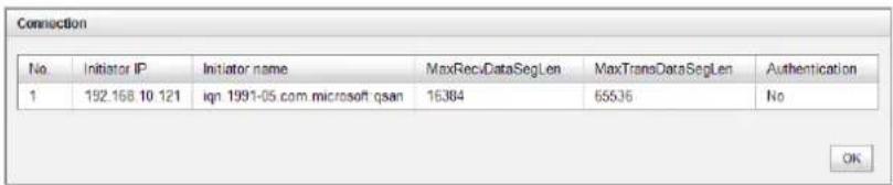
- ▼ → Disconnect: Disconnect the selected session, click the OK button to confirm.
CHAP Accounts
The CHAP Account tab is used to manage the CHAP accounts on the system.
The options available on this tab are:
• Create User: Create a CHAP user.
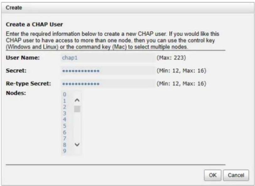
Enter the required information for User Name, Secret, and Re-type Secret.
If you would like this CHAP user to have access, select one or multiple nodes. If selecting none, you can add it later by iSCSI Configuration → iSCSI Nodes → Users.
Click OK button.
Challenge Handshake Authorization Protocol(CHAP).
You can create CHAP users to protect your iSCSI targets from unauthorized access. To create a user, click on the Create User button below.

- ▼ → Modify User Information: Modify the selected CHAP user information.
- ▼ → Delete User: Delete the selected CHAP user.
Volume Configuration
The Volume configuration menu option is for accessing the Physical Disks, RAID Groups, Virtual Disks, Snapshots, Logical Units, and Replications option tabs.
| Physical Disks | RAID Groups | Virtual Disks | Snapshots | Logical Units | Replications |
Physical Disks
The Physical Disks tab provides the status of the hard drives in the system. The two drop-down lists at the top enable you to switch between the local system and any expansion JBOD systems attached. The other is to change the drive size units (MB or GB).
| Slot | Size (GB) | RAID Group | RAID Set | Virtual Disk | Status | Health | Usage | Vendor | Serial Number | Rate | Write Cache | Standby | Read-Ahead | Command Queuing |
| 1 | 1862 | N/A | N/A | Online | Good | Free | WDC | WD-WC4/Y4158095 | SATA 6.0Gb/s | Disabled | Disabled | Enabled | Enabled | |
| 2 | 1862 | N/A | N/A | Online | Good | Free | WDC | WD-WC4/Y3924333 | SATA 6.0Gb/s | Disabled | Disabled | Enabled | Enabled | |
| 3 | 446 | N/A | N/A | Online | Good | Free | INTEL | CVWL414300UZ480QGN | SATA SSD 6.0Gb/s | Enabled | Disabled | Enabled | Enabled |
This table shows the column descriptions.
| Column Name | Description |
| Slot | The position of a hard drive. The button next to the slot number shows the functions that can be executed. |
| Size (GB) or (MB) | Capacity of hard drive. The unit can be displayed in GB or MB. |
| RAID Group | RAID group name. |
| RAID Set | The number of RAID Set:N/A: The RAID group is traditional provisioning.Number: The RAID group is the number of RAID set to thin provisioning. |
| Virtual Disk | Virtual disk name for SSD caching. |
| Status | The status of the hard drive:Online: The hard drive is online.Rebuilding: The hard drive is being rebuilt.Transitioning: The hard drive is being migrated or is replaced by another disk when rebuilding occurs.Scrubbing: The hard drive is being scrubbed. |
| Health | The health of the hard drive:Good: The hard drive is good.Failured: The hard drive has failed.Error Alert: S.M.A.R.T. error alerts.Read Errors: The hard drive has unrecoverable read errors. |
| Usage | The usage of the hard drive:RAID: This hard drive has been set to a RAID group.Free: This hard drive is free for use.Dedicated Spare: This hard drive has been set as a dedicated spare of a RAID group.Local Spare: This hard drive has been set as local spare of the enclosure.Global Spare: This hard drive has been set as global spare of whole system. |
| Vendor | Hard drive vendor. |
| Serial Number | Hard drive serial number. |
| Rate | Hard drive rate:• SAS 6.0Gb/s.• SAS 3.0Gb/s.• SATA 6.0Gb/s.• SATA 3.0Gb/s.• SATA 1.5Gb/s.• SAS SSD 6.0Gb/s.• SATA SSD 6.0Gb/s. |
| Write Cache | Hard drive write cache is enabled or disabled. The default value is Enabled. |
| Standby | HDD auto spin down to save power. The default value is Disabled. |
| Read-Ahead | This feature ensures data is loaded to disk's buffer in advance for further use. The default value is Enabled. |
| Command Queuing | Newer SATA and most SCSI disks can queue multiple commands and handle each command individually. The default value is Enabled. |
The options available on this tab are:
- Disk Health Check: Check the health of the selected disks. It cannot check the disks currently in use.
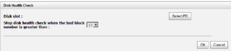
- Disk Check Report: Download the disk check report. It's available after executing Disk Health Check.
- ▼ → Set Free Disk: Make the selected hard drive free for use.
- ▼ → Set Global Spare: Set the selected hard drive to global spare for all RAID groups.
- ▼ → Set Local Spare: Set the selected hard drive to a local spare for the RAID groups located in the same enclosure.
- Set Dedicated Spare: Set a hard drive to a dedicated spare of the selected RAID group.
- ▼ → Upgrade: Upgrade the firmware of the hard drive.
- Disk Scrub: Scrub the hard drive. It's not available when the hard drive is in use.
- Read Error Cleared: Clean the read error of the hard drive.
- ▼ → Turn on/off the indication LED: Turn on the indication LED of the hard drive. Click it again to turn off.
- ▼ → More information: Display the hard drive details.
Take for example setting the physical disk to a dedicated spare disk.
- Check ▼ → Set Dedicated Spare at one physical disk.

- If there is any RAID group which is in protected RAID level and can be set with a dedicated spare disk, select one RAID group, and then click OK button.

TIP: For DSN-6200/6500Series, the maximum number of physical drives in a system is 256.
RAID Groups
The RAID Groups tab is provided to create, modify, delete, or view the status of the RAID groups. Use the drop-down list at the top to change the drive size units (MB or GB).
Select the traditional RAID group, the following will be displayed.

This table shows the column descriptions.
| Column Name | Description |
| Name | RAID group name. |
| Total (GB) or (MB) | Total capacity of the RAID group. The unit can be displayed in GB or MB. |
| Free Capacity (GB) or (MB) | Free capacity of the RAID group. The unit can be displayed in GB or MB. |
| Available Size (GB) or (MB) | Available capacity of the RAID group. The unit can be displayed in GB or MB. |
| Thin Provisioning | The status of Thin provisioning:Disabled.Enabled. |
| Disks Uses | The number of physical disks in the RAID group. |
| Number of Virtual Disk | The number of virtual disks in the RAID group. |
| Status | The status of the RAID group:Online: the RAID group is online Offline: the RAID group is offline.Rebuilding: the RAID group is being rebuilt.Migrating: the RAID group is being migrated.Scrubbing: the RAID group is being scrubbed. |
| Health | The health of the RAID group:Good: the RAID group's health is good.Failure: the RAID group has failed.Degraded: the RAID group is not healthy and not completed. The reason could be lack of disk(s) or a failed disk. |
| RAID | The RAID level of the RAID group. |
| Current Controller (This option is only visible when dual controllers are installed.) | The controller of the RAID group. The default is controller 1. |
| Preferred Controller (This option is only visible when dual controllers are installed.) | The preferred controller of the RAID group. The default is controller 1. |
The options available on this tab are:
• Create: Create a RAID group.
The options available after creating a RAID group are:
- Migrate RAID Level: Change the RAID level of a RAID group. Please refer to the next chapter for details.
- ▼ → Move RAID Level: Move the member disks of RAID group to totally different physical disks.
- ▼ → Activate/Deactivate: Activate or deactivate the RAID group after disk roaming.
Activate can be executed when the RAID group status is offline. Conversely, Deactivate can be executed when the status is online. These are for online disk roaming purpose.
- Verify Parity: Regenerate parity for the RAID group. It supports the RAID level 3 / 5 / 6 / 30 / 50 / 60.
- ▼ → Delete: Delete the RAID group.
- ▼ → Change Preferred Controller: Set the RAID group ownership to the other controller.
- ▼ → Change RAID Options: Change the RAID property options.
Write Cache:
Enabled: When the write cache is enabled, data transfer operations are written to fast cache memory instead of being written directly to disk. This may improve performance but will also increase the risk of losing data when losing power if there is no BBM protection.
√ Disabled: Disable disk write cache. (Default)
Standby:
√ Disabled: Disable auto spin down. (Default)
30 sec / 1 min / 5 min / 30 min: The hard drives will be spun down for power saving when the disk is idle for the period of time specified.
Read-Ahead:
Enabled: The system will discern what data will be needed next based on what was just retrieved form disk and then preload this data into the disks buffer. This feature will improve performance when the data being retrieved is sequential. (Default)
√ Disabled: Disable disk read ahead.
Command Queuing:
Enabled: Sends multiple commands at once to a disk to improve performance. (Default)
√ Disabled: Disable disk command queuing.
- ▼ → Add RAID Set: Add RAID sets for the thin provisioning RAID group.
- ▼ → Add Policy: Add policy for the thin provisioning RAID group.
- ▼ → More information: Display RAID group's information.
Select the thin provisioning RAID group, it will be displayed as below. There are two more tables to describe the properties of the thin provisioning RAID group, RAID Set and RAID Group Policy.

This table shows the column descriptions of RAID Set.
| Column Name | Description |
| No | The number of the RAID set. |
| Total Size(GB) | Total capacity of the RAID set. |
| Free Size (GB) | Free capacity of the RAID set. |
| Disks Used | The number of physical disks in the RAID set. |
| RAID Cell | The number of RAID cells in the RAID set. |
| Status | The status of the RAID group:Online: the RAID group is online Offline: the RAID group is offline.Rebuilding: the RAID group is being rebuilt.Migrate: the RAID group is being migrated.Scrubbing: the RAID group is being scrubbed. |
| Health | The health of the RAID group:Good: the RAID group's health is good.Failed: the RAID group has failed.Degraded: the RAID group is not healthy and not completed. The reason for this could be lack of disk(s) or a disk has failed. |
The options available on this tab are:
- ▼ → Remove: Remove the selected RAID set.
- ▼ → Move RAID Level: Move the member disks of the RAID set to other physical disks.
• ▼ → List Disks: Display all disks.
This table shows the column descriptions of RAID Group Policy.
| Column Name | Description |
| No | The number of the RAID group policy. |
| Threshold | The threshold of the thin provision RAID group. |
| Level | Define the event log level when the thin provision RAID group usage reaches the threshold. |
| Action | Take action when the thin provision RAID group usage reaches the threshold.Take no Action.Reclaim Space.Delete Snapshots.De-activate RAID Group. |
The options available on this tab are:
• ▼ → Delete: Delete the selected policy.
- Modify: Modify the level and the action of the policy.
Take an example of creating a RAID group.
- Click the Create button.

- Enter a RAID Name for the RAID group.
- Select a RAID Level from the drop-down list.
- Click the Select Disks button to select disks from either local or expansion JBOD systems, and click OK to complete the selection. The selected disks are displayed at RAID Disks.
- Optionally, configure the following:
Preferred Controller: This option is only visible when dual controllers are installed. The default value is Auto.
Thin Provisioning: This option is only visible when the thin provisioning feature is enabled. The default value is Disabled.
Write Cache: Enable or disable the write cache option of the hard drives. The default value is Disabled.
Standby: Enable or disable the auto spin down function of the hard drives. When this option is enabled and the hard drives have no I/O access after a certain period of time, they will spin down automatically. The default value is Disabled.
Read-Ahead: Enable or disable the read ahead function. The default value is Enabled.
Command Queuing: Enable or disable the hard drives' command queue function. The default value is Enabled.
- At the confirmation dialog, click OK button to create the RAID group.

TIP:
• For the DSN-6200/6500 Series the maximum number of physical drives in a RAID group is 64.
Virtual Disks
The Virtual Disks tab is provided to create, modify, delete, or view the status of the virtual disk. Use the drop-down list at the top to change the drive size units (MB or GB).

This table shows the column descriptions.
| Column Name | Description |
| Name | Virtual disk name. |
| Size (GB) or (MB) | Total capacity of the virtual disk. The unit can be displayed in GB or MB. |
| SSD Caching | The SSD caching policy:Disable: Disable SSD caching.Database: Enable SSD caching and set it as database policy.File System: Enable SSD caching and set it as file system policy.Web Service: Enable SSD caching and set it as web service policy.Custom: Enable SSD caching and set it as customization policy. |
| Write | The right of virtual disk:WT: Write Through.WB: Write Back.RO: Read Only. |
| Priority | The priority of virtual disk:HI: High priority.MD: Middle priority.LO: Low priority. |
| Bg Rate | Background task priority:4 / 3 / 2 / 1 / 0: Default value is 4. The higher the background priority of a VD is, the more background I/O will be scheduled to execute. |
| Type | The type of the virtual disk:RAID: the virtual disk is normal.BACKUP: the virtual disk is for backup usage. |
| Clone | The clone target name of the virtual disk. |
| Schedule Clone | The clone schedule of the virtual disk. |
| Status | The status of the virtual disk:Online: The virtual disk is online Offline: The virtual disk is offline.Initiating: The virtual disk is being initialized.Rebuilding: The virtual disk is being rebuilt.Migrating: The virtual disk is being migrated.Rollback: The virtual disk is being rolled back.Parity checking: The virtual disk is being parity check. |
| Health | The health of virtual disk:Optimal: the virtual disk is working well and there is no failed disk in the RG.Degraded: At least one disk from the RG of the Virtual disk is failed or plugged out.Failed: the RAID group disk of the VD has single or multiple failed disks than its RAID level can recover from data loss.Partially optimal: the virtual disk has experienced recoverable read errors. After passing parity check, the health will become Optimal. |
| R % | Ratio (%) of initializing or rebuilding. |
| RAID | RAID level. |
| LUN # | Number of LUN(s) that the virtual disk is attached to. |
| Snapshot space (GB) or (MB) | The virtual disk size that is used for a snapshot. The number means Used snapshot space / Total snapshot space. The unit can be displayed in GB or MB. |
| Snapshot # | Number of snapshot(s) that have been taken. |
| RAID Group | The RAID group name of the virtual disk |
The options available on this tab are:
• Create: Create a virtual disk.
- Cloning Options: Set the clone options. Described in detail in chapter 5.
These options are available after creating a virtual disk:
- ▼ -> Extend: Extend the virtual disk capacity.
- ▼ -> Set SSD Caching: Set SSD caching for the virtual disk. Described in detail in chapter 5.
-
▼ -> Verify Parity: Execute parity check for the virtual disk. It supports RAID 3 / 5 / 6 / 30 / 50 / 60. The options are:
-
Verify and repair data inconsistencies.
Only verify for data inconsistencies. Stop verifying when 1 10 20 30 40 50 60 70 80 90 100 inconsistencies have been found.
- ▼ -> Delete: Delete the virtual disk.
- ▼ -> Set Properties: Change the virtual disk name, cache mode, priority, bg rate and read ahead.
Cache Mode:
Write-through Cache: A caching technique in which the completion of a write request is not signaled until data is safely stored in non-volatile media. Data is synchronized in both data cache and accessed physical disks.
Write-back Cache: A caching technique in which the completion of a write request is signaled as soon as the data is in cache and actual writing to non-volatile media occurs at a later time. It speeds up system write performance but needs to bear the risk where data may be inconsistent between data cache and the physical disks in one short time interval. (Default)
√ Read-Only: Set the volume to be read-only, any write request is forbidden.
Priority:
√ High Priority (Default)
√ Medium Priority.
√ Low Priority.
Bg Rate:
√ 4 / 3 / 2 / 1 / 0: Default value is 4. The higher number the background priority of a virtual disk has, the more background I/O will be scheduled to execute.
Read-Ahead:
Enabled: The system will discern what data will be needed next based on what was just retrieved form disk and then preload this data into the disks buffer. This feature will improve performance when the data being retrieved is sequential. (Default)
√ Disabled: Disable disk read ahead.
AV-Media Mode:
√ Enabled: Enable AV-media mode for optimizing video editing.
√ Disabled: Disable AV-media mode. (Default)
。 Type:
√ RAID: The virtual disk is normal. (Default)
√ Backup Target: The virtual disk is used for clone or Replication usage.
- ▼ -> Space Reclamation: Reclaim space for the virtual disk.
- ▼ -> Attach LUN: Attach a logical unit number to the virtual disk.
- ▼ -> Detach LUNs: Detach a logical unit number from the virtual disk.
- ▼ -> List LUNs: List all of the attached logical unit numbers.
- ▼ -> Set Clone: Set the target virtual disk for clone.
- ▼ -> Clear Clone: Clear the clone function.
- ▼ -> Start Clone: Start the clone function.
- ▼ -> Stop Clone: Stop the clone function.
- ▼ -> Change Replication Options: Change the clone to Replication relationship.
- ▼ -> Schedule Clone: Set the clone function by schedule.
- ▼ -> Set Snapshot Space: Set snapshot space for preparing to take snapshots.
- ▼ -> Cleanup Snapshots: Clean all snapshots of the virtual disk and release the snapshot space.
- ▼ -> Take a Snapshot: Take a snapshot on the virtual disk.
- ▼ -> Schedule Snapshots: Set the snapshots by schedule.
- ▼ -> List Snapshots: List all snapshots of the virtual disk.
- ▼ -> More Information: Show the detail information of the virtual disk.
Take an example of creating a virtual disk.
1. Click Create button.
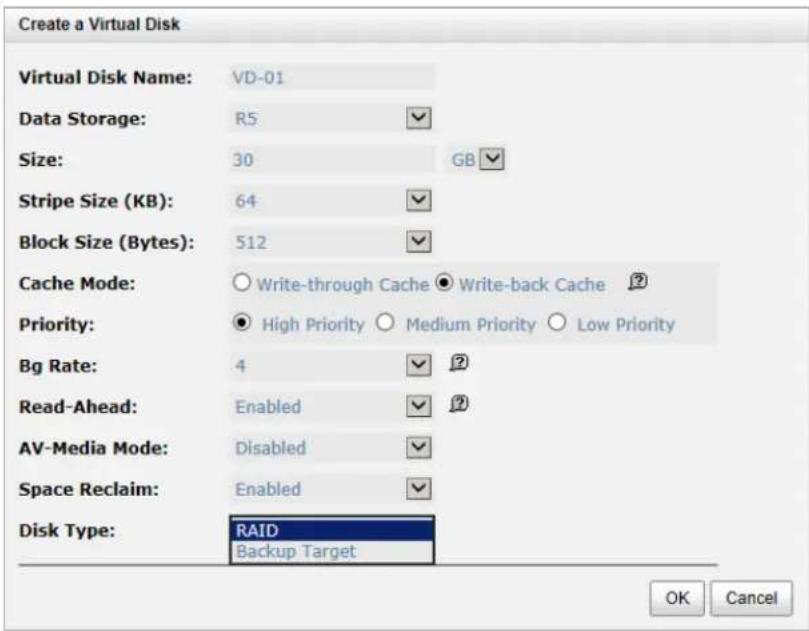
- Enter a Virtual Disk Name for the virtual disk.
- Select a Data Storage from the drop-down list.
- Enter your required Size.
- Optionally, configure the following:
Stripe Size (KB): The options are 4KB, 8KB, 16KB, 32KB, and 64KB. The default value is 64KB.
- Block Size (Bytes): The options are 512 to 65536. The default value is 512 bytes.
Cache Mode: The options are Write-through Cache and Write-back Cache. The default value is Write-back Cache.
Priority: The options are High, Medium and Low Priority. The default value is High priority.
Bg Rate: Background task priority. The higher number the background priority of a virtual disk has, the more background I/O will be scheduled to execute. The options are 0 to 4. The default value is 4.
Read-Ahead: The system will discern what data will be needed next based on what was just retrieved form disk and then preload this data into the disks buffer. This feature will improve performance when the data being retrieved is sequential. The default value is Enabled.
AV-Media Mode: Optimize for video editing. The default value is Disabled.
Erase: This option is available when the RAID group is not thin provisioning. This option will wipe out old data in the virtual disk to prevent OS from recognizing the old
partition. The options are Do Not Erase, erase First 1GB or Full Disk. The default value is Don Not Erase.
Space Reclaim: This option is available when the RAID group is thin provisioning. The default value is Enabled.
Fast Rebuild: This option is available when the RAID group is not RAID 0. The default value is Disabled.
Disk Type: Select type for normal or backup usage. The options are RAID (for general usage) and Backup Target (for Clone or Replication). The default value is RAID.
-
Click OK button to create the virtual disk.
-
At the confirmation message, click OK button.

TIP:
- In DSN-6200/6500 Series, the maximum number of virtual disks in a RAID group is 96. The maximum host number per virtual disk is 16. The maximum host number per controller is 64. The maximum virtual disk number in a system is 2048. The max virtual disk number for snapshot is 32.

CAUTION:
If the system shutdown or rebooted when creating a virtual disk, the erase process will stop.
Snapshots
The Snapshots tab is provided to create, modify, delete, or view the status of snapshot. The two drop-down lists at the top enable you to switch the virtual disks. The other is to change the drive size units (MB or GB).

This table shows the column descriptions.
| Column Name | Description |
| No. | Number. |
| Name | Snapshot name. |
| Used (GB) or (MB) | The amount of the snapshot space that has been used. The unit can be displayed in GB or MB. |
| Status | The status of the snapshot:N/A: The snapshot is normal.Replicated: The snapshot is for clone or Replication usage.Abort: The snapshot is out of space and will abort. |
| Health | The health of the snapshot:Good: The snapshot is good.Failed: The snapshot has failed. |
| Exposure | The snapshot is exposed or not. |
| Cache Mode | The cache mode of the snapshot:N/A: Unknown when the snapshot is unexposed.Read-write: The snapshot can be read / write.Read-only: The snapshot is read only. |
| LUN # | Number of LUN(s) that snapshot is attached to. |
| Time Created | The created time of the snapshot. |
The options available on this tab are:
• Set Snapshot Space: Set snapshot space for preparing to take snapshots.
• Schedule Snapshots: Set the snapshots by schedule.
• Take a Snapshot: Take a snapshot on the virtual disk.
- Cleanup Snapshots: Clean all snapshots of the virtual disk and release the snapshot space.
The options available after taking a snapshot are:
- ▼ -> Set Quota: Set the snapshot quota.
- ▼ -> Rollback: Rollback the snapshot.
- ▼ -> Delete: Delete the snapshot.
The options available after setting the quota of the snapshot are:
- ▼ -> Unexpose: Unexpose the snapshot VD.
- ▼ -> Attach LUN: Attach a logical unit number to the snapshot.
- ▼ -> Detach LUNs: Detach a logical unit number from the virtual disk.
- ▼ -> List LUNs: List all of the attached logical unit numbers.
Take an example of taking a snapshot.
- Before taking a snapshot, it must reserve some storage space for saving variant data. Click Set Snapshot Space button.

- Select a Virtual Disk from the drop-down list.
- Enter a Size which will be reserved for the snapshot space.
- Click OK. The snapshot space is created.
- Click Take a Snapshot button.
- Use the drop-down list to select a Virtual Disk.
- Enter a Snapshot Name.
- Click OK. The snapshot is taken.

- Set quota to expose the snapshot. Click ▼ -> Set Quota option.
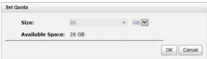
- Enter a size which is reserved for the snapshot. If the size is zero, the exposed snapshot will be read only. Otherwise, the exposed snapshot can be read / written, and the size will be the maximum capacity for writing.
- Attach LUN to the snapshot.
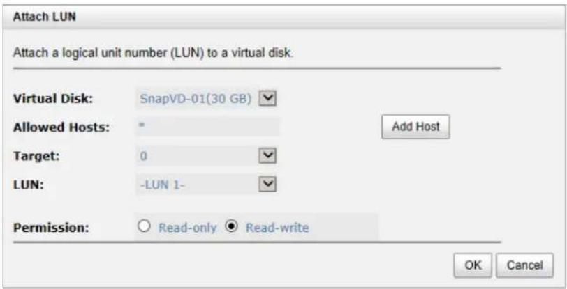
- Done. The Snapshot can be used.

TIP:
• For DSN-6200/6500 Series, the maximum snapshot number per virtual disk is 64.
Logical Units
The Logical Units tab is provided to attach, detach or view the status of logical unit numbers for each virtual disk.
| Allowed Hosts | Target | LUN | Permission | Virtual Disk | Number of Session | |
| * | 0 | 0 | Read-write | VD-01 | 0 | |
| iqn.1991-05.com.microsoft | 0 | 1 | Read-only | VD-02 | 0 |
Attach LUN
This table shows the column descriptions.
| Column Name | Description |
| Allowed Hosts | iSCSI node name for access control or a wildcard (*) for access by all hosts. |
| Target | The number of the target. |
| LUN | The number of the LUN assigned. |
| Permission | The permission level:Read-write.Read-only. |
| Virtual Disk | The name of the virtual disk assigned to this LUN. |
| Number of Session(This option is only visible when | The number of the active connection linked to the logical unit. |
the controller has iSCSI ports.)
The options available on this tab are:
- Attach LUN: Attach a logical unit number to the virtual disk.
The options available after attaching LUN are:
- ▼ -> Detach LUNs: Detach a logical unit number from the virtual disk.
- Click the Attach LUN button.
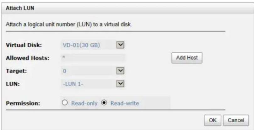
- Select the Protocol. (FC models only)
- Select a Virtual Disk from the drop-down list.
- Enter the Allowed Hosts with semicolons (;) or click Add Host button to add each individually. Fill-in wildcard (*) for access by all hosts.
- Select a Target number from the drop-down list.
- Select a LUN from the drop-down list.
- Check the Permission level.
- Click OK button.
The matching rules of access control are followed from created time of the LUNs. The earlier created LUN is prior to the matching rules. For example: there are 2 LUN rules for the same VD, one is “*”, LUN 0; and the other is “iqn.host1”, LUN 1. The host “iqn.host2” can login successfully because it matches the rule 1.
Wildcard “*” and “?” are allowed in this field. “*” can replace any word. “?” can replace only one character. For example:
- "iqn.host?" -> "iqn.host1" and "iqn.host2" are accepted.
- "iqn.host*" -> "iqn.host1" and "iqn.host12345" are accepted.
This field cannot accept comma, so "iqn.host1, iqn.host2" stands a long string, not 2 iqns.

TIP:
• For DSN-6200/6500 Series, the maximum LUN number is 2048.
Replication
The Replications tab is provided to create, rebuild, delete, or manage the replication tasks.
Physical Disks
RAID Groups
Virtual Disks
Snapshots
Logical Units
Replications
This table shows the "Task" column descriptions.
| Column Name | Description |
| No. | Number. |
| Source Virtual Disk | The source name of the virtual disk. |
| Status | The status of the task:• Online: The task is online.• Missing: The task is missing. |
| % | Ratio (%) of the replication task. |
| Shaping | Apply the number of the shaping group. |
| Speed (MB) | Replication speed. |
| Target Virtual Disk | The target name of the virtual disk. |
| Size (GB) or (MB) | Total capacity of the target virtual disk. |
| Schedule | The status of the schedule:• N/A: No schedule for the replication task.• Icon: The schedule of the replication task is set. |
| Time Created | The created time of the task. |
| Vendor | The target of the vendor. |
| Model | The target of the model. |
| Serial Number | The WWN of the target virtual disk. |
This table shows the "Task Path" column descriptions.
| Column Name | Description |
| No. | Number. |
| Source NIC | The NIC port of the source side for the replication task. |
| Target IP | The IP address of the target side. |
| Target Name | The iSCSI node name of the target side. |
| LUN | The number of the LUN assigned. |
| State | The state of the connection: |
- Connected: The replication task pair is connected.
• Reconnecting: The source is reconnecting to the target.
The options available on this tab are:
• Create: Create a replication task.
• Rebuild: Rebuild the replication task which is changed from a cloning job.
• Replication Options: Set replication options.
• Shaping Setting Configuration: Set task shaping configurations.
The following options are available after creating a replication task in the "Task" table:
- ▼ -> Start: Start the replication task.
- ▼ -> Stop: Stop the replication task.
- ▼ -> Set Task Shaping: Set task shaping group.
- ▼ -> Add Path: Add multi path for the replication task.
- ▼ -> Schedule: Set the replication task by schedule.
- ▼ -> Delete: Delete the replication task.
The following options are available after creating a replication task in the "Task Path" table:
- ▼ -> Add Connection: Add a connection to the replication task.
- ▼ -> Delete Connection: Delete the connection for the replication task.
- ▼ -> Delete: Delete a multi path of the replication task.
Described in detail in chapter 5.
Enclosure Management
The Enclosure Management menu option is for accessing the Hardware Monitor, UPS, SES, and S.M.A.R.T. option tabs.
Hardware Monitor
UPS
SES
S.M.A.R.T.
For the enclosure management, there are many sensors for different purposes, such as temperature sensors, voltage sensors, hard disk status, fan sensors, power sensors, and LED status. Due to the different hardware characteristics among these sensors, they have different polling intervals. Below are the details of the polling time intervals:
• Temperature sensors: 1 minute.
• Voltage sensors: 1 minute.
• Hard disk sensors: 10 minutes.
- Fan sensors: 10 seconds. When there are 3 errors consecutively, the system sends an ERROR event log.
• Power sensors: 10 seconds, when there are 3 errors consecutively, the system sends an ERROR event log.
• LED status: 10 seconds.
Hardware Monitor
The Hardware Monitor tab displays the information of current voltages and temperatures as well as providing an Auto shutdown option.
| Type | Item | Value | Status |
| Voltage | On Board Vcore | +0.99 V (min = +0.75 V, max = +1.35 V) | OK |
| Voltage | Onboard +3.3V | +3.34 V (min = +3.10 V, max = +3.50 V) | OK |
| Voltage | Onboard +5V | +5.00 V (min = +4.60 V, max = +5.40 V) | OK |
| Voltage | Onboard +12V | +12.04 V (min = +11.04 V, max = +12.96 V) | OK |
| Voltage | On Board Vddr | +1.50 V (min = +1.39 V, max = +1.60 V) | OK |
| Temperature | CPU Core 0 | +48.0 (C) (hyst = +5.0 (C), high = +79.0 (C)) | OK |
| Temperature | CPU Core 1 | +46.0 (C) (hyst = +5.0 (C), high = +79.0 (C)) | OK |
| Temperature | ISCSI NIC 1 | +36.0 (C) (hyst = +0.0 (C), high = +65.0 (C)) | OK |
| Temperature | ISCSI NIC 2 | +36.0 (C) (hyst = +0.0 (C), high = +65.0 (C)) | OK |
| Temperature | System Board | +40.0 (C) (hyst = +5.0 (C), high = +65.0 (C)) | OK |
| Temperature | SAS Expander | +63.0 (C) (hyst = +5.0 (C), high = +90.0 (C)) | OK |
| Temperature | Location BBM | N/A | Not installed |
Backplane
| Type | Item | Value | Status |
| Voltage | PSU +5V | +5.07 V (min = +4.60 V, max = +6.40 V) | OK |
| Voltage | PSU +12V | +12.08 V (min = +11.04 V, max = +12.96 V) | OK |
| Voltage | PSU +3.3V | +3.38 V (min = +3.04 V, max = +3.56 V) | OK |
| Temperature | Location 1 | +26.0 (C) (hyst = +0.0 (C), high = +55.0 (C)) | OK |
| Temperature | Location 2 | +29.0 (C) (hyst = +0.0 (C), high = +55.0 (C)) | OK |
| Temperature | Location 3 | +26.0 (C) (hyst = +0.0 (C), high = +55.0 (C)) | OK |
| Temperature | Location 4 | +25.0 (C) (hyst = +0.0 (C), high = +55.0 (C)) | OK |
| Temperature | Location 5 | +26.0 (C) (hyst = +0.0 (C), high = +55.0 (C)) | OK |
| Temperature | Location 6 | +25.0 (C) (hyst = +0.0 (C), high = +55.0 (C)) | OK |
| Temperature | Location 7 | +25.0 (C) (hyst = +0.0 (C), high = +55.0 (C)) | OK |
| Temperature | Location 8 | +25.0 (C) (hyst = +0.0 (C), high = +55.0 (C)) | OK |
| Power Supply | PSU1 | N/A | OK |
| Power Supply | PSU2 | N/A | OK |
| Cooling | FAN1 | 3375 RPM | OK |
| Cooling | FAN2 | 3690 RPM | OK |
| Cooling | FAN3 | 3515 RPM | OK |
| Cooling | FAN4 | 3515 RPM | OK |
Auto Shutdown: √
| If auto shutdown is enabled, the system will shut down automatically when the internal power |
| Apply |
If Auto Shutdown is checked, the system will shut down automatically when the voltage or temperature is out of the normal range. For better data protection, it is recommended to check Auto Shutdown.
For better protection and avoiding a single short period of high temperatures that could trigger an automatic shutdown, the system will gauge if a shutdown is needed. This is done using several sensors placed on key systems that the system checks every 30 seconds for present temperatures.
• The core processor temperature limit is 80^ C.
• The interface temperature limit is 65^ C.
• The SAS Controller and SAS Expand or temperature limits are 65^ C.
When one of these sensors reports a temperature above the threshold for three continuous minutes, the system shuts down automatically.
UPS
The UPS tab is used to set up a UPS (Uninterruptible Power Supply).
The system supports Smart-UPS made by APC, and Megatec series UPS.
Choose Smart-UPS for APC products, Megatec-UPS for Megatec series products, or none if you are using a UPS
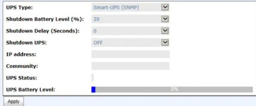
Currently, the system only supports and communicates with Smart-UPS series by APC (American Power Conversion Corp, http://www.apc.com/) and Megatec UPS.

TIP:
Connection with other vendors of UPS can work well, but they have no such communication features with the system.
We support the traditional UPS via serial port and network UPS via SNMP. If using the UPS with a serial port, connect the system to UPS via the included cable for communication. (The cable plugs into the serial cable that comes with the UPS.) Then set up the shutdown values for when the power goes out.
This table shows the available options and their descriptions.
| Options | Description |
| UPS Type | Select UPS Type:None: No UPS or other vendors.Smart-UPS (Serial port): APC UPS with serial port.Smart-UPS (SNMP): APC UPS with network function.Megatec-UPS: Megatec UPS. |
| Shutdown Battery Level (%) | When below the setting level, the system will shut down. Setting level to “0” will disable UPS. |
| Shutdown Delay (Seconds) | If power failure occurs and system power cannot recover after the time setting, the system will shut down. Setting delay to “0” will disable the function. |
| Shutdown UPS | Select ON, when the power is off, the UPS will shut down by itself after the system shutdown is successful. After the power comes back on, UPS will start working and notify system to boot up. OFF will not. |
| IP Address (This option is only visible when the UPS type is Smart-UPS (SNMP).) | The IP address of the network UPS. |
| Community (This option is only visible when the UPS type is Smart-UPS (SNMP).) | The SNMP community of the network UPS. |
| Status | The status of UPS:Detecting...RunningUnable to detect UPSCommunication lostUPS reboot in progressUPS shutdown in progressBatteries failed. Please change them NOW! |
| Battery level (%) | Current power percentage of battery level. |
The system will shut down when either the Shutdown battery level (%) or Shutdown Delay (Seconds) reaches the set condition. Users should set these values carefully.
SES
The SES (SCSI Enclosure Services, one of the enclosure management standards) tab is used to enable or disable the management of SES.
SCSI Enclosure Services (SES)
SES is an enclosure management standard. Use this screen to enable or disable SES
| Allowed Hosts | Target | LUN |
| * | 0 | 0 |
Disable
The options available on this tab are:
- Enable: Click the Enable button to enable SES.
• Disable: Click the Disable button to disable SES.
The SES client software is available at the following web site:
SANtools: http://www.santools.com/
S.M.A.R.T.
S.M.A.R.T. (Self-Monitoring Analysis and Reporting Technology) is a diagnostic tool for hard drives to deliver warnings of drive failures in advance. It provides users a chance to take action before a possible drive failure.
| Self-Monitoring Analysis and Reporting Technology (S.M.A.R.T.) |
| Below is the current S.M.A.R.T. information for the drives attached to this device. |
| S.M.A.R.T. provides users with an opportunity to take action before possible drive failure. |
| Show information for: Local ▼ Temperature (Internal)/(Case): (C) ▼ |
| Slot | HDD Rate | Media Wea | Reallocated Sec | Erase Fall ( | Unexpected Pc | Uncorrectable | Temperatur | Read Error | Spin Up (Time) | Seek Error #R | Spin Up (Ret) | Calibration (Rt) |
| 1 | SATA 6.0Gb/s | N/A | 200(140) | N/A | N/A | N/A | N/A | 200(51) | 177(21) | 200(0) | 100(0) | 100(0) |
| 2 | SATA 6.0Gb/s | N/A | 200(140) | N/A | N/A | N/A | N/A | 200(51) | 161(21) | 200(0) | 100(0) | 100(0) |
| 3 | SATA 8.0Gb/s | N/A | 200(140) | N/A | N/A | N/A | N/A | 200(51) | 168(21) | 200(0) | 100(0) | 100(0) |
S.M.A.R.T. measures many attributes of the active hard drives and inspects the properties of those hard drives that are close to being out of acceptable tolerance levels. The advanced notice of possible hard drive failure can allow users to back up the hard drive or replace the hard drive. This is much better than having a hard drive crash when it is writing data or rebuilding a failed hard drive.
This tool displays S.M.A.R.T. information of hard drives. The number is the current value; the number in parenthesis is the threshold value. The threshold values from different hard drive vendors are different. Please refer to the hard drive vendors' specification for details.
S.M.A.R.T. only supports SATA drives. SAS drives do not have this function and will show N/A in the web page.
System Maintenance
The System Maintenance menu accesses System Information, Event Log, Upgrade, Firmware Synchronization (This option is only visible when dual controllers are installed.), Reset to Factory Defaults, Configuration Backup, Volume Restoration, and Reboot and Shutdown option tabs.
| System Information | Event Log | Upgrade | Firmware Synchronization | Reset to Factory Defaults | Configuration Backup | Volume Restoration | Reboot and Shutdown |
System Information
The System Information tab displays system information. It includes CPU Type, Installed System Memory, Firmware Version, SAS IOC Firmware No., SAS Expander Firmware No., MAC/SAS Address, Controller Hardware No., Master Controller, Backplane ID, JBOD MAC/SAS Address, Status, Error Message (This item is only visible when the system status is Degraded or Lockdown.), Replication and Thin Provisioning status.
This table shows the status descriptions.
| Status | Description |
| Normal | Dual controllers and JBODs are in normal stage. |
| Degraded | One controller or JBOD fails or has been unplugged. |
| Lockdown | The firmware of two controllers is different or the size of memory of two controllers is different. |
| Single | Single controller mode. |
The options available on this tab are:
• Download System Information: Download the system information for debugging.

CAUTION:
If you try to increase the system memory while running dual controller mode, please make sure both controllers have the same DIMM on each corresponding memory slot. Failing to do so will result in controller malfunction, which will not be covered by warranty.
Event log
The Event Log tab provides a log or event messages.
The options available on this tab are:
- Download: Save the event log as a text file with file name "log-ModelName-SerialNumber-Date-Time.txt". It will pop up a filter dialog as the following. The default is "Download all event logs".
Download Event Logs
Download all event logs
○10% of the latest event logs
○20% of the latest event logs
The latest 24 hours event logs
The latest 7 days event logs
○The latest 31 days event logs
OK
Cancel
• Mute Buzzer: Turn off the system alert alarm.
• Clear: Clear all event logs.

TIP:
Plug-in any of the first four hard drives to enable event logs to be saved and displayed in next system boot up. Otherwise, the event logs cannot be saved and will disappear.
| Type | Time | Content |
| Information | Mon, 17 Feb 2014 18:35:56 | [CTR1] Disk 1 has been freed from RAID group 'R5'. |
| Information | Mon, 17 Feb 2014 18:35:56 | [CTR1] Virtual disk 'VD-02' has been deleted. |
| Information | Mon, 17 Feb 2014 18:35:56 | [CTR1] Virtual disk 'SnapVD-01' has been deleted. |
| Information | Mon, 17 Feb 2014 18:35:56 | [CTR1] Virtual disk 'VD-01' has been deleted. |
| Information | Mon, 17 Feb 2014 18:35:56 | [CTR1] RAID group 'R5' has been deleted. |
| Information | Mon, 17 Feb 2014 18:35:42 | [CTR1] LUN 1 is attached to virtual disk 'VD-01'. |
| Information | Mon, 17 Feb 2014 18:35:34 | [CTR1] Disk 2 has been freed from RAID group 'R5'. |
| Error | Mon, 17 Feb 2014 18:35:34 | [CTR1] Virtual disk 'VD-02' has failed. |
| Error | Mon, 17 Feb 2014 18:35:34 | [CTR1] Virtual disk 'VD-01' has failed. |
| Error | Mon, 17 Feb 2014 18:35:34 | [CTR1] RAID group 'R5' has failed. |
| Information | Mon, 17 Feb 2014 18:35:26 | [CTR1] Disk 3 has been freed from RAID group 'R5'. |
| Warning | Mon, 17 Feb 2014 18:35:26 | [CTR1] RAID group 'R5' is in degraded mode. |
| Information | Mon, 17 Feb 2014 18:23:47 | [CTR1] admin login from 192.168.8.231 via web UI. |
| Information | Sat, 15 Feb 2014 20:54:24 | [CTR1] admin login from 92.242.203.131 via web UI. |
| Information | Fri, 14 Feb 2014 15:42:28 | [CTR1] admin login from 59.125.120.109 via web UI. |
| Information | Fri, 14 Feb 2014 15:01:17 | [CTR1] admin login from 203.117.200.77 via web UI. |
| Information | Thu, 13 Feb 2014 11:46:00 | [CTR1] admin login from 192.168.135.1 via web UI. |
| Information | Wed, 12 Feb 2014 21:57:00 | [CTR1] Virtual disk 'VD-02' has completed rebuilding. |
| Information | Wed, 12 Feb 2014 21:42:25 | [CTR1] Virtual disk 'VD-02' has started rebuilding. |
| Information | Wed, 12 Feb 2014 21:42:25 | [CTR1] Virtual disk 'VD-01' has completed rebuilding. |
The event logs are displayed in chronological order; the latest event log is on the first / top page. They are actually saved in the first four hard drives; each hard drive has one copy of the event log. For each system, there are four copies of event logs to make sure users can check an event log any time when there are failed disks.
Upgrade
The Upgrade tab is used to upgrade controller firmware, JBOD firmware, and change operation mode. Before upgrading, we recommend first using Configuration Backup tab to export all configurations.
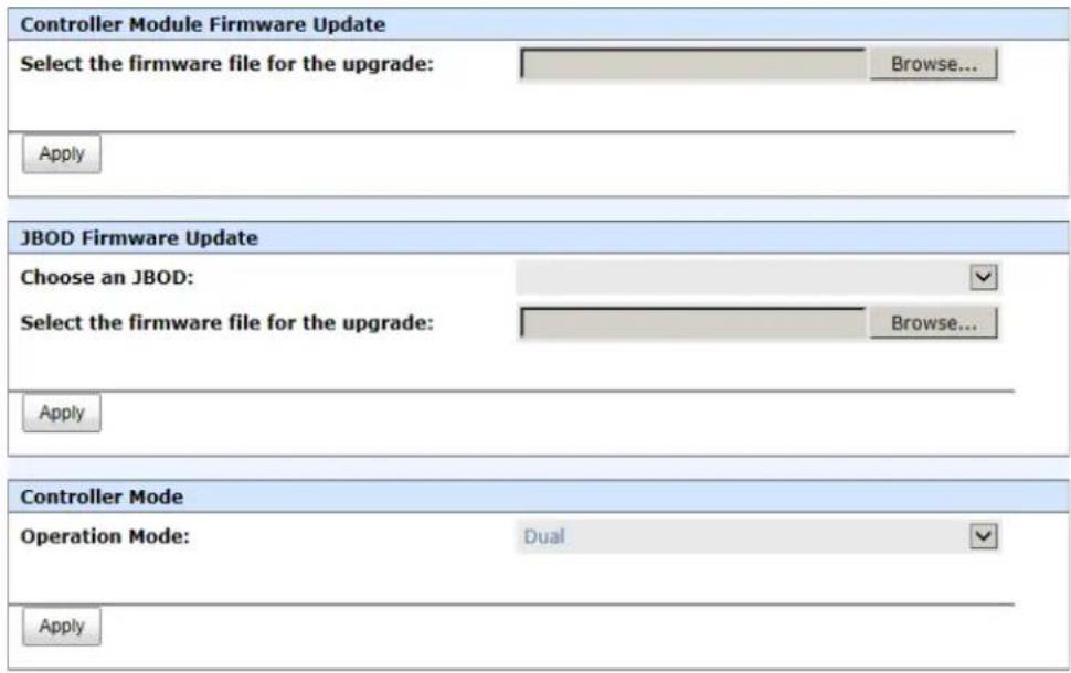
The options available on this tab are:
- Controller Module Firmware Update: Please prepare new controller firmware file named "xxxx.bin" in local hard drive, then click Browse to select the firmware file. Click the Apply button, it will pop up a warning message, click the OK button to start upgrading the firmware.
When upgrading, there is a progress bar running. After finished upgrading, the system must reboot manually to make the new firmware take effect.
- JBOD Firmware Update: To upgrade JBOD firmware, choose a JBOD first, the other steps are the same as controller firmware update.
- Controller mode: This option can be modified to dual or single here. If the system installs only one controller, switch this mode to Single, and then click Apply button.
Firmware Synchronization (Only available in Dual controller models)
The Firmware Synchronization tab is used on dual controller systems to synchronize the controller firmware versions when the firmware of the master controller and the slave controller are different. The firmware of the slave controller is always changed to match the firmware of the master controller. It doesn't matter if the firmware version of the slave controller is newer or older than that of the master. Normally, the firmware versions in both controllers are the same.
The firmware versions are the same between the two controllers.
Apply
If the firmware versions between two controllers are different, it will display the following message. Click the Apply button to synchronize.
The firmware versions are different between the two controllers. To copy controller one's firmware to controller Two, click the Apply button below.
Apply

TIP:
This tab is only visible when the dual controllers are installed. A single controller system does not have this option.
Reset to Factory Defaults
The Reset to factory defaults tab allows users to reset the system configurations back to the factory default settings.
Click the Reset button below to reset the system to the factory defaults.
Reset
The default values are:
• Management IP Address: 192.168.0.32
- User Name: admin
• Password: 123456
Configuration Backup
The Configuration Backup is used to either save system configuration (export) or apply a saved configuration (import).
Import or Export:
Import File:

Apply
While the volume configuration settings are available for exporting, to prevent conflicts and overwriting existing data, they cannot be imported.
The options available on this tab are:
- Import: Import all system configurations excluding volume configuration.
• Export: Export all configurations to a file.

CAUTION: Import option will import all system configurations excluding volume configuration and the current system configurations will be replaced.
Volume Restoration
The Volume Restoration can restore the volume configuration from the volume creation history. It is used for RAID group corrupt and tries to recreate the volume. When trying to do data recovery, the same volume configurations as the original must be set and all member disks must be installed by the same sequence as original or else data recovery will fail. The volume restoration does not guarantee that the lost data can be restored. Please get help from the expert before executing the function.
| RAID Group Name | RAID | Virtual Disk | Volume Size (GB) | Disks Used | Disk Slot | Time | Event Log | |
| ▼ | 1 | RAID 5 | 3 | 300 | 3 | Local: 1, 2, 3 | 2014/02/17 18:52:41 CST | The virtual disk is created. |
| Restore | RAID 5 | 2 | 200 | 3 | Local: 1, 2, 3 | 2014/02/17 18:52:35 CST | The virtual disk is created. | |
| ▼ | 1 | RAID 5 | 1 | 100 | 3 | Local: 1, 2, 3 | 2014/02/17 18:52:29 CST | The virtual disk is created. |
| ▼ | R5 | RAID 5 | VD-02 | 50 | 1 | Local: 1 | 2014/02/17 18:35:34 CST | Physical disk is removed from the system. |
| ▼ | R5 | RAID 5 | VD-01 | 30 | 1 | Local: 1 | 2014/02/17 18:35:34 CST | Physical disk is removed from the system. |
| ▼ | R5 | RAID 5 | VD-02 | 50 | 2 | Local: 1, 2 | 2014/02/17 18:35:26 CST | Physical disk is removed from the system. |
| ▼ | R5 | RAID 5 | VD-01 | 30 | 2 | Local: 1, 2 | 2014/02/17 18:35:26 CST | Physical disk is removed from the system. |
| ▼ | R5 | RAID 5 | VD-02 | 50 | 3 | Local: 1, 2, 3 | 2014/02/11 17:03:30 CST | The snapshot space has initialized. |
| ▼ | R5 | RAID 5 | VD-02 | 50 | 3 | Local: 1, 2, 3 | 2014/02/11 17:03:08 CST | The virtual disk is created. |
| ▼ | R5 | RAID 5 | VD-01 | 30 | 3 | Local: 1, 2, 3 | 2014/02/11 17:02:45 CST | The snapshot space has initialized. |
| ▼ | R5 | RAID 5 | VD-01 | 30 | 3 | Local: 1, 2, 3 | 2014/02/11 17:00:04 CST | The virtual disk is created. |
| ▼ | QUICK13645 | RAID 5 | QUICK21222 | 3725 | 3 | Local: 3, 2, 1 | 2014/02/11 14:46:51 CST | The virtual disk is created. |
<< first < prey 1 2 3 4 5 6 7 8 next > last >>
This table shows the column descriptions.
| Column Name | Description |
| RAID Group Name | The original RAID group name. |
| RAID | The original RAID level. |
| Virtual Disk | The original virtual disk name. |
| Volume Size (GB) | The original capacity of the virtual disk. |
| Disks Used | The original physical disk number of the RAID group. |
| Disk slot | The original physical disk location. |
| Time | The last action time of the virtual disk. |
| Event Log | The last event of the virtual disk. |
| The options available on this tab are:Restore:Restore the virtual disk of the RAID group. | |
 | TIP:When trying to do data recovery, the same volume configurations as the original must be set and all member disks must be installed by the same sequence as original or else data recovery will fail. |
 | CAUTION:The data recovery does not guarantee that the lost data can be restored 100%. It depends on the real operation and the degree of physical damages on disks. Users will take their own risk to do these procedures. |
Reboot and Shutdown
The Reboot and Shutdown function is used to reboot or shutdown the system. Before powering off the system, it is highly recommended to execute the Shutdown function to flush the data from cache onto the physical disks. This step is important for data protection.

Reboot

Shutdown
The Reboot function has three options. These are reboot both controllers, controller 1 only or controller 2 only.

Performance Monitor
The Performance Monitor menu option accesses the Disk and iSCSI.
Disk
The Disk displays the throughput and latency of the physical disk. Check the slots for which disk you want to monitor.

iSCSI
The iSCSI displays TX (Transmission) and RX (Reception) of the iSCSI ports. Check the interfaces that you want to monitor.


line
| TX | RX | |-------|--------| | 400.94 | 331.71 |
line
| Time (ms) | Tc | Rx | | --------- | ------ | ------- | | 0 | 414.32 | 508.55 |
line
| Time | TTK (Mbps) | RO (Mbps) | |------|------------|-----------| | 0 | 405.34 | 335.75 |
line
| Time | TX: 635.01 Mbps | RX: 633.72 Mbps | |------|-----------------|-----------------| | 0 | 635.01 | 633.72 |Advanced Operations
5
Volume Rebuild
If one physical disk of the RAID group which is set as protected RAID level (e.g.: RAID 5, or RAID 6) fails or has been removed, then the status of RAID group will be changed to degraded mode. At the same time, the system will search the spare disk to volume rebuild the degraded RAID group into a complete one.
There are three types of spare disks which can be set in Physical Disks:
• Dedicated Spare: The hard drive has been set as a dedicated spare of a RAID group.
- Local Spare: The hard drive has been set as a local spare of the enclosure.
• Global Spare: The hard drive has been set as a global spare of the whole system.
The detection sequence first checks for a dedicated spare disk, then local spare disk and finally global spare disk.
The following examples are scenarios for a RAID 6.
- When there is no global spare disk or dedicated spare disk in the system, the RAID group will be in degraded mode and wait until there is one disk assigned as a spare disk, or the failed disk is removed and replaced with a new clean disk, before starting Auto-Rebuild.
- When there are spare disks for the degraded array, system starts Auto-Rebuild immediately. In RAID 6, if there is another disk failure occurs during rebuilding, system will start the above Auto-Rebuild process as well. Auto-Rebuild feature only works while the status of the RAID group is Online. Thus, it will not conflict with the online roaming feature.
- In degraded mode, the health of the RAID group is Degraded. When rebuilding, the status of the RAID group and virtual disk will display Rebuilding, the column R% in virtual disk will display the ratio in percentage. After complete rebuilding, the status will become Online.

TIP:
The dedicated spare cannot be set if there is no RAID group or only RAID groups with RAID 0 or JBOD level.
Sometimes, rebuild is called recover; they are the same meaning. This table describes the relationship between RAID levels and recovery.
| Operation | Description |
| RAID 0 | Disk striping. No protection for data. RAID group fails if any hard drive fails or is unplugged. |
| RAID 1 | Disk mirroring over 2 disks. RAID 1 allows one hard drive to fail or be unplugged. You need one new hard drive to be inserted into the system for rebuild to be completed. |
| N-way mirror | Extension to RAID 1 level. It has N copies of the disk. N-way mirror allows N-1 hard drives to fail or be unplugged. |
| RAID 3 | Striping with parity on the dedicated disk. RAID 3 allows one hard drive to fail or be unplugged. |
| RAID 5 | Striping with interspersed parity over the member disks. RAID 5 allows one hard drive to fail or be unplugged. |
| RAID 6 | 2-dimensional parity protection over the member disks. RAID 6 allows two hard drives to fail or be unplugged. If it needs to rebuild two hard drives at the same time, it will rebuild the first one, and then the other in sequence. |
| RAID 0+1 | Mirroring of RAID 0 volumes. RAID 0+1 allows two hard drives to fail or be unplugged, but on the same array. |
| RAID 10 | Striping over the member of RAID 1 volumes. RAID 10 allows two hard drives to fail or be unplugged, but in different arrays. |
| RAID 30 | Striping over the member of RAID 3 volumes. RAID 30 allows two hard drives to fail or be unplugged, but in different arrays. |
| RAID 50 | Striping over the member of RAID 5 volumes. RAID 50 allows two hard drives fail or be unplugged, but in different arrays. |
| RAID 60 | Striping over the member of RAID 6 volumes. RAID 60 allows four hard drives to fail or be unplugged, two per array. |
| JBOD | The abbreviation of “Just a Bunch Of Disks”. No data protection. RG fails if any hard drive failures or unplugs. |
Migrate and Move RAID Groups
Migrate RAID Level function changes the RAID group to different RAID level or adds the member disks of the RAID group for larger capacity. Usually, the RAID group migrates to higher RAID level for better protection. To do migration, the total size of RAID group must be larger than or equal to the original RAID group. The limitation is that it's not allowed to expand the same RAID level with the same physical disks of the original RAID group. There is a similar function Move RAID Level which moves the member disks of the RAID group to totally different physical disks. In addition, the thin provision RAID group cannot execute migrate or move, it uses Add RAID Set to enlarge capacity. This is described more detail in the Thin Provision section.
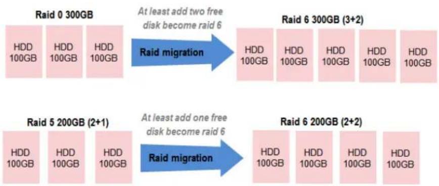
flowchart
graph LR
    A["Raid 0 300GB"] -->|At least add two free disk become raid 6| B["Raid 6 300GB (3+2)"]
    B --> C["Raid migration"]
    D["Raid 5 200GB (2+1)"] -->|At least add one free disk become raid 6| E["Raid 6 200GB (2+2)"]
    E --> F["Raid migration"]
There are some limitations when a RAID group is being migrated or moved. The system will reject these operations:
- Add dedicated spare.
- Remove a dedicated spare.
- Create a new virtual disk.
- Delete a virtual disk.
- Extend a virtual disk.
- Scrub a virtual disk.
- Perform another migration operation.
- Scrub entire RAID group.
- Take a snapshot.
- Delete a snapshot.
- Expose a snapshot.
- Rollback to a snapshot.

TIP:
Migrate function will migrate the member disks of RAID group to the same physical disks but it should increase the number of disks or it should be a different RAID level. The Move function will move the member disks of a RAID group to totally different physical disks.

CAUTION:
RAID group migration or moving cannot be executed during rebuilding or virtual disk extension.
Take the example of migrating RAID group.
- Select Volume Configuration -> RAID Groups.
- Select a RAID group, and then click ▼ -> Migrate RAID Level.
-
Select a RAID Level from the drop-down list.
-
Click the Select Disks button to select disks from either local or expansion JBOD systems, and click OK to complete the selection. The selected disks are displayed at Disks Used.

- In the confirmation dialog, click the OK button to execute migration.
- Migration starts and the status of Physical Disks, RAID Groups and Virtual Disks are changing. The complete percentage of migration is displayed in R%.

| Name | Total (GB) | Free Capacity (GB) | Available Size (GB) | Thin Provisioning | Disk Used | Number of Virtual Disk | Status | Health | RAIO | Current Controller | Preferred Controller | |
| ✓ | R0->R5 | 3725 | 3625 | 3625 | Disabled | 3 | 1 | Negating | Good | RAIO 5 | Controller 1 | Controller 1 |
| Cerase: | ||||||||||||

Move RAID Level usage is the same as Migrate RAID Level except it cannot change the RAID level.
Extend Virtual Disks
Extend function extends the size of the virtual disk if there is enough free space.
Take an example of extending the virtual disk.
- Select Volume Configuration -> Virtual Disks.
-
Select a virtual disk, and then click ▼ -> Extend.
-
Change the virtual disk size. The size must be larger than the current, and then click the OK button to start extension.
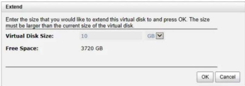
- Extension starts. If the virtual disk needs initialization, it will display the status Initiating and the complete percentage of initialization in R%.

TIP: The extension size must be larger than the current size of the virtual disk.

CAUTION: The extension cannot be executed during rebuilding or migration.
Thin Provisioning
Thin provisioning is a hot topic in the IT management and storage industry. When we think of thin provisioning, it naturally brings to our minds the opposite term - fat provisioning, which is the traditional way IT administrators allocate storage space. Each logical volume is used by an application or a group of users. When it comes to the point to decide how much space a logical volume requires for three years or for the lifetime of an application, it's really hard to make the prediction correctly and precisely. To avoid the complexity of adding more space to the volumes frequently, IT administrators end up allocating more storage space to each logical volume than it needs in the beginning. This is why it's called "fat" provisioning. Usually it turns out that a lot of free space is sitting around idle. This stranded capacity is wasted, which equals to waste of investment and inefficiency. Various studies indicate that as much as 75% of the storage capacity in small and medium enterprises or large data centers is allocated but unused. This wasted storage capacity is where thin provisioning becomes useful.

bar_stacked
| System Type | Actual | Physical | Available space | | ------------- | ------ | -------- | --------------- | | Volume | 10 | 10 | 0 | | Volume | 15 | 15 | 0 | | Whole System | 20 | 20 | 10 |Traditional Fat Provisioning
Thin provisioning sometimes is known as just-in-time capacity or over allocation. As the term explains itself, it provides storage space by requests dynamically. Thin provisioning presents more storage space to the hosts or servers connecting to the storage system than is actually available on the storage system. Put it in another way. Thin provisioning allocates storage space that may or may not exist. The whole idea is actually another way of virtualization. Virtualization is always about a logical pool of physical assets and provides better utilization over those assets. Here the virtualization mechanism behind thin provisioning is a storage pool. The capacity of the storage pool is shared by all volumes. When write requests come in, the space will be drawn dynamically from this storage pool to meet the needs.

bar_stacked
| Category | Actual | Physical | Thin provisioning | Available space | | -------------- | ------ | -------- | ----------------- | --------------- | | Volume | 10 | 15 | 5 | 0 | | Volume | 10 | 15 | 5 | 0 | | Whole System | 20 | 25 | 10 | 15 |The Benefits of Thin provisioning
The benefits of Thin provisioning are described below.
• Less disk purchase is needed initially when setting up a new storage system.
You don't need to buy more capacity to meet your future data growth. Usually hard drive price declines as time progresses. You can buy the same hard drives with cheaper price at a later time. Why not save money upfront while you can?
- No stranded storage capacity, better utilization efficiency and lower total cost of ownership. Thin provisioning can make full use of the stranded capacity that traditional provisioning can't. All free capacity can be made available to other hosts. A single storage system can serve more hosts and servers to achieve high consolidation ratio. Thin provisioning can help you achieve the same
level of services with less hard drives purchased upfront, which can significantly reduce your total cost of ownership.
• Scalability: storage pool can grow on demand.
When the storage pool (RAID group) has reached the threshold you set before. Up to 32 RAID sets can be added to the RAID group to increase the capacity on demand without interrupting I/O. Each RAID set can have up to 64 physical disks.
• Automatic space reclamation mechanism to recycle unused blocks.
The technology used here is called zero reclamation. When a thin RG is created, the initialization process will try to fill out all the storage pool space with zero. This process will run in background with low priority in order not to impact the I/O performance. This is the reason why when there is no I/O traffic from the hosts, the hard drive LED will keep blinking as if there are I/O activities. The purpose of zero reclamation is that when the actual user data happens to have all zero in a basic allocation unit (granularity), the storage system will treat it as free space and recycle it. Until the next time there is data update to this reclaimed all zero basic unit, the storage system can swiftly return a basic unit from the free storage pool because it's already filled with zero.
• An eco-friendly green feature that helps to reduce energy consumption.
Hard drive is the top power consumer in a storage system. Because you can use less hard drives to achieve the same amount of work, this translates directly to a huge reduction of power consumption.
Features Highlight
The following describes the comparison between Fat and Thin provisioning.
• Write on demand or allocate on demand.
This is the most distinctive function in thin provisioning. You can see from the screenshots below.
Figure 1 shows there are two RAID groups created. "Fat-RG" is using traditional provisioning without Thin provisioning enabled and its size is 1862GB. "Thin-RG" is Thin provisioning enabled and it's size is the same.
| Name | Total (GB) | Free Capacity (GB) | Available Size (GB) | Thin Provisioning | |
| ▼ | Fat-RG | 1862 | 1862 | 1862 | Disabled |
| ▼ | Thin-RG | 1862 | 1862 | 1862 | Enabled |
Figure 1: No virtual disk is created
Let's create a Virtual Disk on each RAID group with the same size of 1000GB respectively in Figure 2 and see what happens.
| Name | Size (GB) | Write | Priority | Bg Rate | Type | Clone | |
| ▼ | Fat-VD | 1000 | WB | HI | 4 | RAID | N/A |
| ▼ | Thin-VD | 1000 | WB | HI | 4 | RAID | N/A |
Figure 2: Virtual disks are created.
In Figure 3, the free space of "Fat-RG" immediately reduces to 862GB. 1000GB is taken away by the virtual disk. However, the free space of "Thin-RG" is still 1862GB even though the same sized virtual disk is created from the RAID group. Nothing is written to the virtual disk yet, so no space is allocated. The remaining 1862GB can be used to create other virtual disks. This is storage efficiency.
| Name | Total (GB) | Free Capacity (GB) | Available Size (GB) | Thin Provisioning | |
| ▼ | Fat-RG | 1862 | 862 | 862 | Disabled |
| ▼ | Thin-RG | 1862 | 1862 | 1862 | Enabled |
Figure 3: Write on demand
- Expand capacity on demand without downtime.
Extra RAID set can be added to the thin RAID group to increase the size of free storage pool. A thin RAID group can have up to 32 RAID sets with each RAID set containing up to 64 physical hard drives. The maximum size of each RAID set is 64TB. Figure 4 shows that "Thin-RG" consists of two RAID sets.
| Name | Total (GB) | Free Capacity (GB) | Available Size (GB) | Thin Provisioning | Disks Used |
| Fat-RG | 1862 | 862 | 862 | Disabled | 1 |
| Thin-RG | 3724 | 3724 | 3724 | Enabled | 2 |
| RAID Set: | |||||
| No | Total Size (GB) | Free Size (GB) | Disks Used | RAID Cell | Status Health |
| 1 | 1862 | 1862 | 1 | 1 | Online Good |
| 2 | 1862 | 1862 | 1 | 1 | Online Good |
Figure 4: Scalable RAID group size
- Allocation unit (granularity) is 1GB. This is a number that demands careful balance between efficiency and performance. The smaller it is, the better the efficiency and the worse the performance becomes, and vice versa.
• Thin provisioned snapshot space and it is writeable.
Snapshot space sits at the same RAID group of the volume that the snapshot is taken against.
Therefore when you expose the snapshot into a virtual disk, it becomes a thin-provisioned virtual disk. It will only take up the just the right amount of space to store the data, not the full size of the virtual disk.
- Convert traditional virtual disk to Thin and vice versa.
Move all your existing fat-provisioned virtual disks to thin-provisioned ones. Virtual disk clone function can be performed on both directions - fat-to-thin and thin-to-fat, depending on your application needs. Figure 5 shows cloning a fat virtual disk to a thin one.

Figure 5: Clone between thin virtual disk and fat one
Thin Provisioning Options
The following describes the thin provisioning options.
• Threshold settings and capacity policies.
These are designed to simplify the management and better monitor the storage usage. You can set as many as 16 policies for each RAID group. When space usage ratio grows over the threshold set in the policy, the action will be taken and event log will be generated.
| Name | Total (GB) | Free Capacity (GB) | Available Size (GB) | Thin Provisioning | Disks Used | |
| Fat-RG | 1862 | 360 | 360 | Disabled | 1 | |
| Thin-RG | 3724 | 3722 | 3724 | Enabled | 2 |
RAID Set:
| No | Total Size (GB) | Free Size (GB) | Disks Used | RAID Cell | Status | Health | |
| ▼ | 1 | 1862 | 1862 | 1 | 1 | Online | Good |
| ▼ | 2 | 1862 | 1860 | 1 | 1 | Online | Good |
RAID Group Policy:
| No | Threshold | Level | Action | |
| 1 | 60% | Information | Take no Action | |
| 2 | 70% | Information | Take no Action | |
| 3 | 80% | Information | Take no Action | |
| 4 | 85% | Warning | Reclaim Space | |
| 5 | 90% | Warning | Delete Snapshots | |
| 6 | 95% | Warning | De-activate RAID Group |
Figure 6: Capacity policy settings
• Automatic space reclamation to recycle unused space and increase utilization rate. Automatic space reclamation will be automatically activated in RAID group initialization process or it can be set manually through capacity policy. You can set as many as 16 policies. When space usage ratio grows over the threshold set in the policy, space reclamation will be enabled automatically in the background with the lowest priority or when the I/O is low. The resource impact is reduced to a minimum.

Figure 7: Space reclamation
Thin Provisioning Case
We suggest that you apply Thin provisioning to non-critical production applications first. Thin provisioning works well when the data written is thin-friendly, which means that the data written is not completely spread across the whole volume. Applications that spread metadata across the
entire volume will prevent the advantages of thin provisioning. Some applications that expect the data to be contiguous at block level are not good candidates for thin provisioning either.
Thin provisioning works well with email systems, web-based archives, or regular file archive systems. When the number of supported volumes grows larger, the benefits of Thin provisioning will become more apparent.
Disk Roaming
Physical disks can be re-sequenced in the same system or move all physical disks in the same RAID group from system-1 to system-2. This is called disk roaming. T system can execute disk roaming online. Please follow the procedure below:
- In Volume Configuration -> RAID Group tab, select a RAID group. And then click Deactivate.
- Click OK to apply. The Status changes to Offline.
- Move all physical disks of the RAID group to another system.
- In Volume Configuration -> RAID Group tab, select the snapshot. And then click ▼ -> Activate.
- Click OK to apply. The Status changes to Online.

Disk roaming has some constraints as described below:
- Check the firmware version of two systems first. It is better that either systems have the same firmware version, or that the firmware version of the system-2 is newer.
- All physical disks of the RAID group should be moved from system-1 to system-2 together. The configuration of both RAID group and virtual disk will be kept but LUN configuration will be cleared in order to avoid conflict with the current setting of the system-2.
JBOD Expansion
D-Link storage space can be expanded by adding JBOD expansion system.
Connecting JBOD
D-Link storage systems support expansion systems with SAS connections. When connecting to an expansion system, it will be displayed at the Show disk for: drop-down list in Volume
Configuration -> Physical Disks tab. For example: Local, JBOD 1 (DSN-6020), ...etc. Local means disks in local controller, JOBD 1 means disks in JBOD 1 controller, and so on.
In Enclosure Management -> Hardware monitor tab, select the enclosure at the Show information for: drop-down list, it can display the hardware status of SAS JBODs.
In Enclosure Management -> S.M.A.R.T. tab, select the enclosure at the Show information for: drop-down list, it can display the SMART information of the disks in JBODs.
SAS JBOD expansion has some constraints as described below:
- Users can create RAID groups among multiple chassis. The maximum number of disks in a single RAID group is 32.
- Local spare disks can support the RAID groups that are located in the local chassis.
- Global spare disks can support all RAID groups that are located in different chassis.
- When supporting SATA drives for the redundant JBOD model, the 6G MUX board is required. The 3G MUX board does not apply to this model.
- The following table is the maximum JBOD numbers and maximum HDD numbers with different chassis that can be cascaded.
Upgrade Firmware
Before upgrading, it is recommended to use the System maintenance -> Configuration Backup tab to export all configurations to a file. To upgrade the firmware of JBOD, please follow the procedures.
- In System Maintenance -> Upgrade tab, choose JBOD first, and then click Browse to select the firmware file.

- Click Apply button, it will pop up a warning message, click the OK button to start upgrading the JBOD firmware.
- After upgrading has finished, the JBOD system must reboot manually to make the new firmware take effect.
MPIO and MC/S
These features come from iSCSI initiator. They can be setup from the iSCSI initiator to establish redundant paths for sending I/O from the initiator to the target.
MPIO
In the Microsoft Windows server base system, Microsoft MPIO driver allows initiators to login multiple sessions to the same target and aggregate the duplicate devices into a single device. Each session can be established using different NICs, network infrastructure and target ports. If one session fails, then another session can continue processing I/O without interruption to the application.

flowchart
graph TD
    A["Initiator"] --> B["SCI layer"]
    A --> C["iSCI layer"]
    D["Target"] --> E["SCI layer"]
    D --> F["iSCI layer"]
    B --> G["iSCI layer"]
    C --> H["iSCI layer"]
    E --> I["iSCI layer"]
    F --> J["iSCI layer"]
    G --> K["TCP/IP"]
    H --> L["TCP/IP"]
    I --> M["TCP/IP"]
    J --> N["TCP/IP"]
    style A fill:#f9f,stroke:#333
    style D fill:#f9f,stroke:#333
    style B fill:#ccf,stroke:#333
    style C fill:#ccf,stroke:#333
    style E fill:#ccf,stroke:#333
    style F fill:#ccf,stroke:#333
    style G fill:#cfc,stroke:#333
    style H fill:#cfc,stroke:#333
    style I fill:#cfc,stroke:#333
    style J fill:#cfc,stroke:#333
MC/S
MC/S (Multiple Connections per Session) is a feature of iSCSI protocol, which allows combining several connections inside a single session for performance and failover purposes. In this way, I/O can be sent on any TCP/IP connection to the target. If one connection fails, another connection can continue processing I/O without interruption to the application.

flowchart
graph TD
    A["Initiator"] --> B["Session"]
    B --> C["SCSI layer"]
    C --> D["iSCSI layer"]
    D --> E["iSCSI layer"]
    E --> F["TCP/IP"]
    G["Target"] --> H["Session"]
    H --> I["SCSI layer"]
    I --> J["iSCSI layer"]
    J --> K["TCP/IP"]
    L["iSCSI layer"] --> M["iSCSI layer"]
    M --> N["TCP/IP"]
    O["iSCSI layer"] --> P["iSCSI layer"]
    P --> Q["TCP/IP"]
    R["iSCSI layer"] --> S["iSCSI layer"]
    S --> T["TCP/IP"]
    U["iSCSI layer"] --> V["iSCSI layer"]
    V --> W["TCP/IP"]
    X["Multiple Connections per Session"] --> A
    X --> G
Difference
MC/S is implemented on iSCSI level, while MPIO is implemented on the higher level. Hence, all MPIO infrastructures are shared among all SCSI transports, SAS, etc. MPIO is the most common usage across all OS vendors. The primary difference between these two is the degree at which level the redundancy is maintained. MPIO creates multiple iSCSI sessions with the target storage. Load balance and failover occurs between the multiple sessions. MC/S creates multiple connections within a single iSCSI session to manage load balance and failover. Notice that iSCSI connections and sessions are different than TCP/IP connections and sessions. The above figures describe the difference between MPIO and MC/S.
Here are some considerations for when a user chooses MC/S or MPIO for multi-path.
- If the user uses hardware iSCSI off-load HBA, then MPIO is the only choice.
- If the user needs to specify different load balance policies for different LUNs, then MPIO should be used.
- If the user installs anyone of Windows XP, Windows Vista or Windows 7, then MC/S is the only option since Microsoft MPIO is supported in Windows Server editions only.
- MC/S can provide higher throughput than MPIO in a Windows system, but it consumes more CPU resources than MPIO.
Trunking and LACP
Link aggregation is the technique of taking several distinct Ethernet links and making them appear as a single link. It has a larger bandwidth and provides the fault tolerance ability. Beside the
advantage of wide bandwidth, the I/O traffic remains operating until all physical links fail. If any link is restored, it will be added to the link group automatically.
LACP
The Link Aggregation Control Protocol (LACP) is a part of IEEE specification 802.3ad. It allows the bundling of several physical ports together to form a single logical channel. A network switch negotiates an automatic bundle by sending LACP packets to the peer. Theoretically, the LACP port can be defined as active or passive. D-Link controllers implement it as active mode which means that LACP port sends LACP protocol packets automatically. Please note that you are using the same configurations between the D-Link controller and gigabit switch.
The usage occasion of LACP:
- It's necessary to use LACP in a network environment of multiple switches. When adding new devices, LACP will separate the traffic to each path dynamically.

flowchart
graph TD
    A["Computer 1"] --> B["MPIOor MC/S"]
    C["Computer 2"] --> B
    D["Computer 3"] --> B
    E["Computer 4"] --> B
    F["Computer 5"] --> B
    G["Computer 6"] --> B
    H["Computer 7"] --> B
    I["Computer 8"] --> B
    J["Computer 9"] --> B
    K["Computer 10"] --> B
    L["Computer 11"] --> B
    M["Computer 12"] --> B
    N["Computer 13"] --> B
    O["Computer 14"] --> B
    P["Computer 15"] --> B
    Q["Computer 16"] --> B
    R["Computer 17"] --> B
    S["Computer 18"] --> B
    T["Computer 19"] --> B
    U["Computer 20"] --> B
    V["Computer 21"] --> B
    W["Computer 22"] --> B
    X["Computer 23"] --> B
    Y["Computer 24"] --> B
    Z["Computer 25"] --> B
    AA["Computer 26"] --> B
    AB["Computer 27"] --> B
    AC["Computer 28"] --> B
    AD["Computer 29"] --> B
    AE["Computer 30"] --> B
    AF["Computer 31"] --> B
    AG["Computer 32"] --> B
    AH["Computer 33"] --> B
    AI["Computer 34"] --> B
    AJ["Computer 35"] --> B
    AK["Computer 36"] --> B
    AL["Computer 37"] --> B
    AM["Computer 38"] --> B
    AN["Computer 39"] --> B
    AO["Computer 40"] --> B
    AP["Storage"] --> AQ["LACP"]
    AQ --> AR["Storage"]
Trunking
Trunking is not a standard protocol. It defines the usage of multiple iSCSI data ports in parallel to increase the link speed beyond the limits of any single port.
The usage occasion of Trunking:
- This is a simple SAN environment. There is only one switch to connect the server and storage, and there will be no extra server added in the future.
• There is a request for monitoring the traffic on the trunk in the switch.
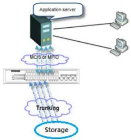
flowchart
graph TD
    A["Application server"] --> B["MC/S or MPIO"]
    B --> C["Storage"]
    B --> D["Trunking"]
    D --> C
    A --> E["Computer"]
    A --> F["Computer"]

CAUTION:
Before using trunking or LACP, the gigabit switch must support either trunking or LACP. Otherwise, the host cannot connect link with the storage device.
Dual Controllers
The D-Link storage system supports dual controllers of the same type for redundancy. Controller 1 (CTRL 1) is the master controller and controller 2 (CTRL 2) is the slave by default.

CAUTION:
- If you try to increase the system memory and are running in dual controller mode, please make sure both controllers have the same DIMM on each corresponding memory slot. Failing to do so will result in controller malfunction, which will not be covered by warranty.
- Be aware that when the LED of the Controller Health is in RED, please DO NOT unplug the controller from the system or turn off the power suddenly. This may cause unrecoverable damage, which will not be covered by warranty.
Perform I/O
Please refer to the following topology and have all the connections ready. To perform I/O on dual controllers, server/host should setup MPIO. MPIO policy will keep I/O running and prevent fail connection with single controller failure.

flowchart
graph TD
    A["Host / Server"] -->|GBE| B["Gigabit switch"]
    C["IGNS server (Recommended)"] -->|GBE| B
    D["Management PC"] -->|R5 232| E["Switch"]
    F["APC Smart UPS (Optional)"] -->|R5 232| E
    B --> G["Network Interface"]
    E --> H["Network Interface"]
    G --> I["To DSN-6020"]
    H --> J["To DSN-6020"]
    style A fill:#f9f,stroke:#333
    style C fill:#f9f,stroke:#333
    style D fill:#f9f,stroke:#333
    style F fill:#f9f,stroke:#333
    style G fill:#ccf,stroke:#333
    style H fill:#ccf,stroke:#333
    style I fill:#dfd,stroke:#333
    style J fill:#dfd,stroke:#333
Ownership
When creating a RAID group, it will be assigned with a preferred owner, the default owner is controller 1. To change the ownership of the RAID group, please follow the procedure below.
- In Volume Configuration -> RAID Group tab, selects a RAID group. And then click Change Preferred Controller.

- Click OK to apply. The ownership of the RG will be switched to the other controller.
Controller Status
There are four statuses for dual controller. They are displayed in the Status column in System Maintenance -> System Information.
- Normal: Dual controller mode. Both of the controllers are functional.
- Degraded: Dual controller mode. When one controller fails or has been un-plugged, the system will turn to Degraded. In this stage, I/O will write through the protected data and the
ownership of RAID group will switch to the working controller. For example, if controller 1, which owns the RAID group 1 fails accidentally, the ownership of RAID group 1 will be switched to controller 2 automatically. The system and data can then keep working well. After controller 1 is fixed or replaced, the current owner of all RAID groups will be assigned back to their preferred owner.
- Lockdown: Dual controller mode. The firmware of two controllers is different or the size of memory of two controllers is different. In this stage, only the master controller can work and I/O will write through the protected data.
- Single: Single controller mode. In this stage, the controller must stay in slot A and MUX boards for SATA drives are not necessary. The differences between single and degraded are described below. There is no error message for one controller only. I/O will not overwrite through and there is no ownership of RAID group.
Change Controller Mode
The operation mode can be changed from Single to Dual or vice versa. Here are the procedures:
- In System Maintenance -> Upgrade tab, choose Single or Dual in the drop-down list.

- Click the Apply button, it will pop up a warning message, click the OK button to confirm.
Recommend iSNS Server
An iSNS server is recommended for helping to manage devices. It's important for keeping I/O running smoothly when the ownership of the RAID group is switching or one of the dual controllers fails. For example, without iSNS server, when the controller 1 fails, the running I/O from host to controller 1 may fail because the host switching to a new portal is slower at that moment and as a result may cause I/O time out. With a iSNS server, this case would not happen.

TIP:
iSNS server is recommended for dual controller system of iSCSI interfaces.
Snapshots
Snapshot-on-the-box captures the instant state of data in the target volume in a logical sense. The underlying logic is Copy-on-Write, moving out the data which would be written to a certain location where a write action occurs since the time of data capture. The certain location, named as "Snapshot virtual disk", is essentially a new virtual disk which can be attached to a LUN provisioned to a host as a disk, like other ordinary virtual disks in the system.
In case of data loss (e.g. virus attack, data corruption, human errors and so on), rollback can restore the data back any previous captured state. Snapshot virtual disk is allocated within the same RAID group in which the snapshot is taken, we suggest to reserve 20% of the RAID group size or more for snapshot space.
Take a Snapshot
Take an example of taking a snapshot.
- Before taking a snapshot, the system must reserve some storage space for saving variant data. There are two methods to set snapshot space. In Virtual Disks tab, selects a virtual disk and then click ▼ -> Set Snapshot Space or in Snapshots tab, click Set Snapshot Space button.

- Enter a Size which is reserved for the snapshot space, and then click the OK button. The minimum size suggested is 20% of the virtual disk size. Now there are two numbers in Snapshot Space (GB) column in Virtual Disks tab. They mean used snapshot space and total snapshot space.
- There are two methods to take snapshot. In the Virtual Disks tab, select a virtual disk and then click ▼ -> Take a Snapshot or in Snapshots tab, click Take a Snapshot button.
- Enter a Snapshot Name, and then click OK button. The snapshot is taken.
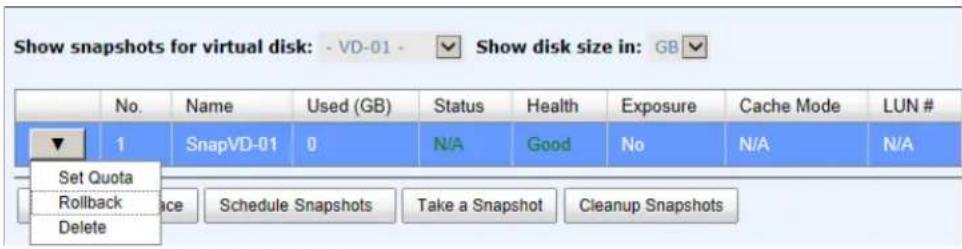
- Set quota to expose the snapshot. Click ▼ -> Set Quota option.

- Enter the size reserved for the snapshot. If the size is zero, the exposed snapshot will be read only. Otherwise, the exposed snapshot can be read / written, and the size will be the maximum capacity for writing.
- Attach LUN to the snapshot.

- Done. The Snapshot can be used.
Cleanup Snapshots
To clean up all the snapshots, please follow the procedures.
- There are two methods to cleanup snapshots. In Virtual Disks tab, select a virtual disk and then click ▼ -> Cleanup Snapshots or in Snapshots tab, click Cleanup Snapshots button.
- Click OK to apply. It will delete all snapshots of the virtual disk and release the snapshot space.
Schedule Snapshots
The snapshots can be taken by schedule such as hourly or daily. Please follow the procedures.
- There are two methods to set schedule snapshots. In Virtual Disks tab, select a virtual disk, and then click ▼ -> Schedule Snapshots or in Snapshots tab, click Schedule Snapshots button.
- Check the schedules that you want. They can be set monthly, weekly, daily, or hourly. Check Auto Mapping to attach LUN automatically when the snapshot is taken and the LUN will be able to be accessed by Allowed Hosts.
- Click OK to apply.
Schedule Snapshots
- VD-01 -
Months to Take Snapshots:

Weeks to Take Snapshots:

Days to Take Snapshots:
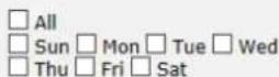
Hours to Take Snapshots:

Minutes to Take Snapshots:

Auto Mapping:

TIP:
A daily snapshot will be taken at every 00:00. A weekly snapshot will be taken every Sunday 00:00. A monthly snapshot will be taken every first day of month 00:00.
Rollback
The data in snapshot can roll back to the original virtual disk. Please follow the procedures.
- In Snapshots tab, select a snapshot and then click ▼ -> Schedule Rollback.
- Click OK to apply.

CAUTION: Before executing rollback, it is better that the disk is unmounted on the host computer for flushing data from cache.
Snapshot Constraint
Snapshot function applies Copy-on-Write technique on virtual disks and provides a quick and efficient backup method. When taking a snapshot, it does not copy any data the first time until a request of data modification comes in. The snapshot copies the original data to a snapshot space and then overwrites the original data with new changes. With this technique, a snapshot only copies the changed data instead of copying whole data, saving you a lot of disk space.
• Create a data-consistent snapshot
Before using snapshot, the user has to know why sometimes the data corrupts after rollback of snapshot. Please refer to the following diagram.
When the user modifies the data from the host, the data will pass through the file system and the memory of the host (write caching). Then the host flushes the data from memory to physical disks, no matter if the disk is local disk, DAS, or SAN. From the viewpoint of the storage device, it cannot control the behavior on the host side. If a snapshot is taken, and some data is still in memory and not on the disk, then the snapshot may have an incomplete image of the original data. The problem does not belong to the storage device. To avoid this data inconsistency issue between snapshot and original data, the user has to make the operating system flush the data from the memory of the host (write caching) into the disk before taking a snapshot.

flowchart
graph TD
    A["User modified data"] -->|I/O| B["File System"]
    B -->|I/O| C["Memory (cache)"]
    C -->|I/O| D["Physical disk (SATA)"]
    C --> E["Physical disk (iSCSI)"]
    C --> F["Physical disk (SAS or Fibre)"]
On Linux and UNIX platform, a command named sync can be used to make the operating system flush data from write caching into disk. For Windows platform, Microsoft also provides a tool – sync, which can do exactly the same thing as the sync command in Linux/UNIX. It will tell the OS to flush the data on demand. For more detail about sync tool, please refer to: http://technet.microsoft.com/en-us/sysinternals/bb897438.aspx
Besides the sync tool, Microsoft develops VSS (volume shadow copy service) to prevent this issue. VSS is a mechanism for creating consistent point-in-time copies of data known as shadow copies. It is a coordinator between backup software, application (SQL or Exchange...) and storage to make sure the snapshot doesn't have the problem of data-inconsistencies. For more detail about the VSS, please refer to http://technet.microsoft.com/en-us/library/cc785914.aspx. The DSN-6200/6500 storage system can support Microsoft VSS.
• What if there is not enough snapshot space?
Before using snapshot, a snapshot space is needed from RAID group capacity. After a period of working snapshot, what if the snapshot size is over the snapshot space defined by the user? There are two different situations:
- If there are two or more snapshots existing, the system will try to remove the oldest of snapshots (to release more space for the latest snapshot) until enough space is released.
- If there is only one snapshot, the snapshot will fail. Because there isn't enough snapshot space.
For example, if there are two or more snapshots existing on a virtual disk and the latest snapshot keeps growing. When it comes to the moment when the snapshot space has run out, the system will try to remove the oldest snapshot to release more space for the latest snapshot usage. As the latest snapshot is growing, the system keeps removing the old snapshots. When it comes that the latest snapshot is the only one in the system, there is no more snapshot space which can be released for incoming changes, then the snapshot will fail.
• How many snapshots can be created on a virtual disk?
There are up to 64 snapshots can be created per virtual disk. What if the 65th snapshot has been taken? There are two different situations:
- If the snapshot is configured as a schedule snapshot, the latest one (the 65th snapshot) will replace the oldest one (the first snapshot) and so on.
- If the snapshot is taken manually, when taking the 65th snapshot it will fail and a warning message will be shown on the Web UI.
- Rollback and delete snapshot
When a snapshot has been rolled back, the related snapshots which are earlier than it will also be removed. But the remaining snapshots will be kept after rollback. If a snapshot has been deleted, the other snapshots which are earlier than it will also be deleted. The space occupied by these snapshots will be released after deleting.
Clone
A clone function can backup data from the source virtual disk to target. Here is the clone operation. At the beginning, copy all data from the source virtual disk to target. This is called full copy. Afterwards, use snapshot technology to perform the incremental copy. Please be fully aware that the incremental copy needs to use snapshot to compare the data difference. Therefore, enough snapshot space for the virtual disk is very important. Of course, clone job can also be set as schedule.
Setup Clone
Take an example of cloning the virtual disk.
- Before cloning, DSN-6200/6500 must prepare backup target virtual disk. In the Virtual Disks tab, click Create button. And then select Disk Type to Backup Target.
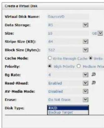
Figure 1: Source side
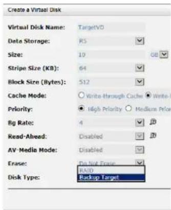
Figure 2: Target side
- Select the source virtual disk, and then click ▼ -> Set Clone.
- Select a target virtual disk, and then click OK button.

- At this time, if the source virtual disk has no snapshot space, it will allocate snapshot space for clone usage automatically. The size will depend on the parameter of Cloning Options.
Start and Stop Clone
To start clone, please follow the procedures.
- Select the source virtual disk, and then click ▼ -> Start Clone.
- Click OK button. The source virtual disk will take a snapshot, and then start cloning.

To stop cloning, please follow the procedures.
- Select the source virtual disk, and then click ▼ -> Stop Clone.
- Click OK button to stop cloning.
Schedule Clone
The clone job can be set by schedule such as hourly or daily. Please follow the procedures.
- Select the source virtual disk, and then click ▼ -> Schedule Clone.
- Check the schedules that you want. They can be set monthly, weekly, daily, or hourly. Click OK to apply.
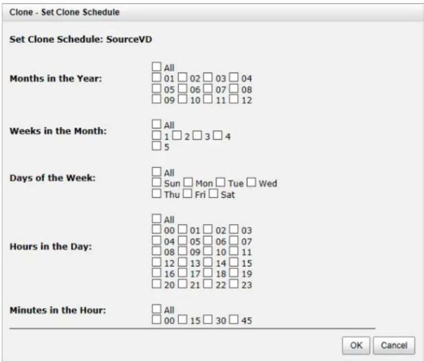

TIP:
Daily clones will be taken at every 00:00. Weekly clones will be taken every Sunday 00:00. Monthly clones will be taken the first day of the month at 00:00.
Cloning Options
There are three clone options, described on the following.

- Snapshot Space: This setting is the ratio of the source virtual disk and snapshot space. If the ratio is set to 2, it means when the clone process is starting, the system will book the free RAID group space to set as the snapshot space which capacity is double the source virtual disk automatically. The options are 0.5 3 .
- Threshold: The setting will be effective after enabling schedule clone. The threshold will monitor the usage amount of the snapshot space. When the used snapshot space achieves the threshold, the system will take a snapshot and start the clone process automatically. The
purpose of threshold could prevent the incremental copy failure immediately when running out of the snapshot space. For example, the default threshold is 50%. The system will check the snapshot space every hour. When the used snapshot space is over 50%, the system will start the clone job automatically. And then continue monitoring the snapshot space. When the rest of the snapshot space reaches 50%, in other words, the total snapshot space that has been used reaches 75%, the system will start the clone job again.
- Restart the task an hour later if failed: The setting will be effective after enabling schedule clone. When running out of the snapshot space, the virtual disk clone process will be stopped because there is no more available snapshot space. If this option is checked, the system will clear the clone snapshots in order to release snapshot space automatically, and the clone task will be restarted after an hour. This task will start a full copy.
Clear Clone
To clear the clone job, please follow the procedures.
- Select the source virtual disk, and then click ▼ -> Clear Clone.
- Click OK button to clear clone job.
Clone Constraint
While the clone is processing manually, the increment data of the virtual disk is over the snapshot space. The clone will complete the task, but the clone snapshot will fail. The next time, when trying to start clone, you will get a warning message “There is not enough snapshot space for the operation”. The user needs to clean up the snapshot space in order to operate the clone process.
Each time the clone snapshot failed, it means that the system loses the reference value of incremental data. So it will start a full copy at the next clone process.
When running out of snapshot space, the virtual disk clone procedure will resemble following diagram.
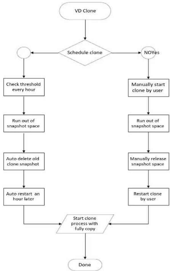
flowchart
graph TD
    A["VD Clone"] --> B{Schedule clone}
    B -->|Yes| C["NOYes"]
    B -->|No| D["Check threshold every hour"]
    D --> E["Run out of snapshot space"]
    E --> F["Auto delete old clone snapshot"]
    F --> G["Auto restart an hour later"]
    G --> H["Start clone process with fully copy"]
    H --> I["Done"]
    B -->|No| J["Manually start clone by user"]
    J --> K["Run out of snapshot space"]
    K --> L["Manually release snapshot space"]
    L --> M["Restart clone by user"]
    M --> H
Replication
The replication function can replicate data easily through LAN or WAN from one system to another. The replication operation is as follows. At the beginning, copy all data from the source virtual disk to target. This is also called a full copy. Afterwards, use snapshot technology to perform an incremental copy. Please be fully aware that the incremental copy needs to use a snapshot to compare the data difference. Therefore, enough snapshot space for the virtual disk is very important. Of course, the replication task can also be set to a schedule.
Create Replication Task
Take an example of creating the Replication task.
- Before replication, it must prepare backup target virtual disk. In the Virtual Disks tab, click Create button, and then select Disk Type to Backup Target.
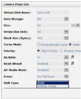
Figure 1: Source Side

Figure 2: Target Side
- After creating the target virtual disk, please also setup snapshot space. The snapshot of the source virtual disk can replicate to the target virtual disk. In the Virtual Disks tab, select the backup virtual disk. And then click ▼ -> Set Snapshot Space.
- Enter a Size which is reserved for the snapshot space, and then click the OK button.
- Attach LUN of the source and target virtual disk separately.

Figure 3: Source Side

Figure 4: Target Side
- In the Replications tab of the source side, click Create.
- Select a target virtual disk, and then click the Next button.
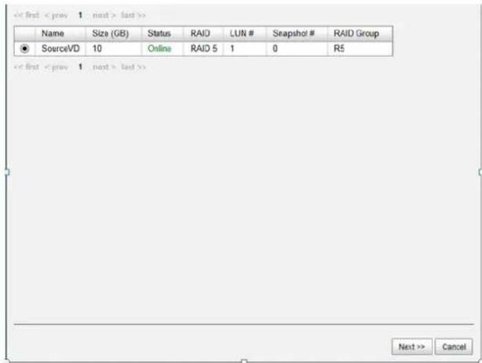
- Select the Source Port and input the Target IP, and then click the Next button.

- Choose Authentication Method and input the CHAP user if needed. Select a Target Node, and then click the Next button.
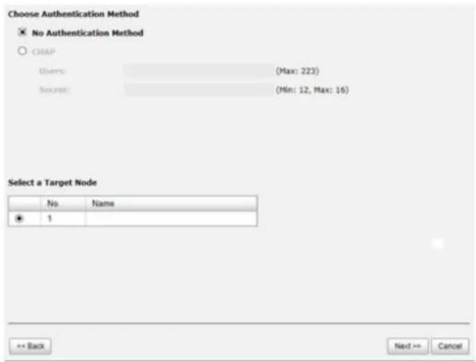
-
Select a Target LUN. When a replication job is complete, it will take a snapshot of its target virtual disk. Please make sure the snapshot space of the backup virtual disk on the target side is properly configured. Finally, click the Finish button.
-
The replication task is created.
-
At this time, if the source virtual disk has no snapshot space, it will be allocated snapshot space for replication usage automatically. The size will depend on the parameters set in Replication Options.
Start and Stop Replication Task
To start replication task, please follow procedure below.
-
In Replications tab of the source side, select the source virtual disk, and then click ▼ -> Start.
-
Click OK button. The source and target virtual disks will take snapshots, and then start replication.

Figure 5: Source side

Figure 6: Target side
To stop the replication task, please follow the procedure below.
-
In Replications tab of the source side, select the source virtual disk, and then click ▼ -> Stop.
-
Click the OK button to stop replication.
MPIO
To setup MPIO (Multi Path Input/Output) of the replication task, please follow the procedure below.
-
Select the task in Replications tab, and then click ▼ -> Add Path.
-
Follow the same steps as the procedure for creating a new replication task.
To delete multi path of the replication task, please follow the procedure below.
-
Select the task in Replications tab, and then click ▼ -> Delete Path.
-
Select the path(s) that you want to be deleted, and then click the OK button.
-
The multi path(s) are deleted.
MC/S
To setup MC/S (Multiple Connections per Session) of the replication task path, please follow the procedure below.
- Select the task path in Replications tab, and then click ▼ -> Add Connection.

- Select the Source Port and input the Target IP, and then click OK button.
- The connection is added.
To delete multi connections per session of the replication task path, please follow the procedure below.
- Select the task path in the Replications tab, and then click ▼ -> Delete Connection.
- Select the connection(s) that you want to be deleted, and then click OK button.
- The multi connection(s) are deleted.
Task Shaping
If the replication traffic is affecting the normal usage, the method below will help to limit it. There are eight shaping groups which can be set. In each shaping group, we also provide peak and off-peak time slots for different bandwidths. The following is an example for setting a shaping group.
- In Replications tab, click the Shaping Setting Configuration button.

- Select a Shaping Group to setup.
- Input the bandwidth (MB) at the Peak time.
- If needed, check Enable Off-Peak, and then input the bandwidth (MB) at Off-Peak time and define the off-peak hour.
- Click OK button.
- In Replications tab, select the task, and then click ▼ -> Set Task Shaping.

- Select a Shaping Group from the drop down list and then click the OK button.
- The shaping group is applied to the replication task.
Schedule Replication Task
The replication task can be set by an hourly or daily schedule. Please follow the procedure below.
-
In the Replications tab, select the task, and then click ▼ -> Schedule.
-
Check the schedules that you want. They can be set by monthly, weekly, daily, or hourly. Click OK to apply.


TIP:
Daily replication will be taken every 00:00. Weekly replication will be taken every Sunday 00:00. Monthly replication will be taken the first day of every month at 00:00.
Replication Options
There are three Replication options, described below:
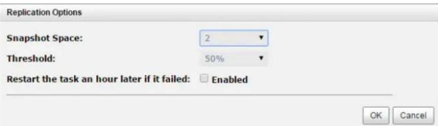
- Snapshot Space: This setting is the ratio of the source virtual disk and snapshot space. If the ratio sets to 2, it means when the replication process is starting, the system will book the free RAID group space to set as the snapshot space which capacity is double the source virtual disk automatically. The options are 0.5 3 .
- Threshold: The setting will be effective after enabling schedule replication. The threshold will monitor the usage amount of the snapshot space. When the used snapshot space achieves the threshold, the system will take a snapshot and start the replication process automatically. The purpose of the threshold is to prevent incremental copy failure immediately when running out of snapshot space. For example, the default threshold is 50%. The system will check the snapshot space every hour. When the used snapshot space is over 50%, the system will start the replication job automatically and then continue monitoring the snapshot space. When the rest snapshot space has been used 50%, in other words, the total used snapshot space is around 75%, the system will start the replication task again.
- Restart the task an hour later if failed: The setting will be effective after enabling schedule replication. When running out of the snapshot space, the virtual disk replication process will be stopped because there is no more available snapshot space. If this option is checked, the system will clear the snapshots of replication in order to release snapshot space automatically, and the replication task will be restarted after an hour. This task will start a full copy.

CAUTION:
The default snapshot space allocated by the system is two times the size of the source virtual disk. That is the best value of our suggestion. If the user sets the snapshot space manually and lower than the default value, the user should be aware that if the snapshot space is not enough, the replication task will fail.
Delete Replication Task
To delete the replication task, please follow the procedures.
-
Select the task in Replications tab, and then click ▼ -> Delete.
-
Click OK button to delete the replication task.
Clone Transfers to Replication
It is always a problem doing a full copy over LAN or WAN when the replication task is executed the first time. It may take days or weeks to replicate data from the source to target within limited network bandwidth. We provide two methods to help users shorten the time of executing a full copy.
- Skip full copy on a new, clean virtual disk. The term "clean" means that the virtual disk has never had data written on it since created. For a new created virtual disk which has not been accessed, the system will recognize it and skip full copy automatically when the replication job is created on this virtual disk the first time.

TIP:
Any IO access to the new created virtual disk will make it "not clean", even executing the "Erase" function when the virtual disk is created. The full copy will take place in such a case.
- The other way is to use virtual disk clone function, which is a local data copy function between virtual disks to execute full copy the first time. Then move all the physical drives of the target virtual disk to the target system and then turn the cloning job into a replication task with differential copy afterward.
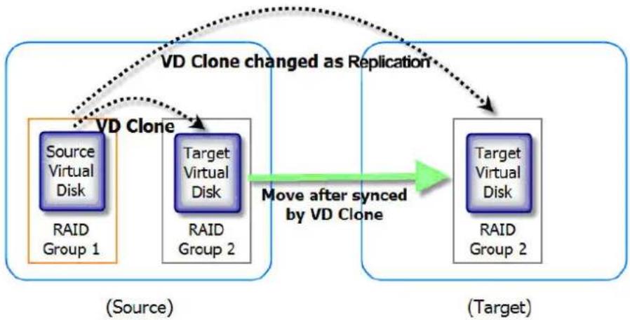
flowchart
graph TD
    A["Source Virtual Disk RAID Group 1"] -->|VD Clone changed as Replication| B["Target Virtual Disk RAID Group 2"]
    B -->|Move after synced by VD Clone| C["Target Virtual Disk RAID Group 2"]
    style A fill:#f9f,stroke:#333
    style B fill:#bbf,stroke:#333
    style C fill:#dfd,stroke:#333
To do virtual disk clone transfers to Replication, please follow the procedure below:
- Create a cloning job on an existing virtual disk with data stored already.
- It is better if there is no host connected to the source virtual disk. Then run Set Clone, Start Clone to synchronize the data between source and target virtual disks.
- After the data is synchronized, change the cloning job to a Replication task. Select the source virtual disk, and then click ▼ -> Change Replication Options.
- The Clone status of the source virtual disk will be changed from the name of the target virtual disk into Replication.
| Name | Size (GB) | Write | Priority | Bg Rate | Type | Clone | |
| ▼ | SourceVD | 10 | WB | HI | 4 | RAID | QRep |
| ▼ | TargetVD | 10 | WB | HI | 4 | BACKUP | N/A |

CAUTION: Changing a cloning job to a replication task is only available when the cloning job has been finished. This change is irreversible.
- Deactivate the RAID group which the target virtual disk resides in and move all physical disks of the RAID group to the target system. Then activate the RAID group in the target system. Remember to set snapshot space for the target virtual disk and then attach the target virtual disk to a LUN ID.
- In Volume Configuration -> Replications tab at the source side, click the Rebuild button to rebuild the replication task which was changed from a cloning job formerly.
- Rebuild the clone relationship, select a source virtual disk.

- The next steps are the same as the procedure of creating a new replication task.
- If a wrong target virtual disk is selected when rebuilding the replication task, there will be an alert and the system stops the creation.
Fast Rebuild
When executing rebuild, the Fast Rebuild feature skips any partition of the virtual disk where no write changes have occurred, it will focus only on the parts that have changed. This mechanism may reduce the amount of time needed for the rebuild task. It also reduces the risk of RAID failure cause of reducing the time required for the RAID status from degraded mode to healthy. At the same time, it frees up CPU resources more quickly to be available for other I/O and demands.
Solution
Without the Fast Rebuild feature [rebuild will start from the beginning partition to the end. It may spend lots of time to complete the task. When enabling Fast Rebuild feature, it will rebuild the partition with the changes only.
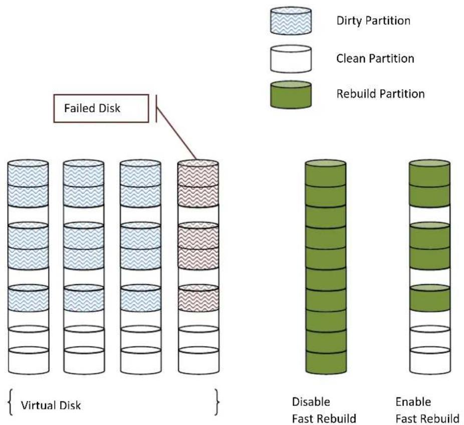
flowchart
graph TD
    A["Failed Disk"] --> B["Virtual Disk"]
    B --> C["Disable Fast Rebuild"]
    C --> D["Enable Fast Rebuild"]
    style A fill:#f9f,stroke:#333
    style B fill:#ccf,stroke:#333
    style C fill:#cfc,stroke:#333
    style D fill:#fcc,stroke:#333

TIP:
With less changed partition, the Fast Rebuild feature may go faster. If the virtual disk is full of changed partition. The rebuild may take the same time without the Fast Rebuild feature.
Configuration
When creating a virtual disk, enable the Fast Rebuild. The default is disabled.

Constraint
Here are some constraints about Fast Rebuild.
- Only thick/fat RAID group supports this feature. Thin provision RAID group already has this feature implemented.
- When rebuilding happens to a fast rebuild virtual disk, clean partitions are not rebuilt since there is no data saved there. Though clean partitions are never rebuilt, their health status is good.
- If all partitions of the fast rebuild virtual disk are clean, then no rebuild will happen and no event would be sent.
- The RAID stacks could not use optimize algorithm to compute parities of a partition which is not rebuilt. Thus, the performance of random write in a clean partition would be worse.

CAUTION: The fast rebuild should not be enabled for a virtual disk whose access pattern is random write.
SSD Caching (licensing fee required)
The traditional storage technology stored in the HDDs (Hard Disk Drives) and SSDs (Solid-State Drives) are mainly used in mission critical applications where the speed of the storage system
needs to be as high as possible. In recent years, the capacity of HDDs has increased but their random input/output (I/O) has not increased at the same rate. For some applications such as enterprise web with database, cloud and virtualization which require both high capacity and performance, HDDs have the superiority in capacity but lower speed. It means the pure HDD storage is not enough for those applications.
Using the superiority of SSDs, offer exceptionally high speed, SSD caching technology provides the best way to fulfill cost-effectively the performance and capacity requirements of their enterprise applications. Integrated HDDs and SSDs into the storage combine the benefits of both. SSD cache feature enables the system to use SSDs as extended cache, thus increasing the performance of random I/O applications such as databases, file servers, and web servers, etc.
Generally, the SSD caching is useful for the following features:
- Due to the HDD IOPS, read performance cause the bottleneck.
- In working space, read I/O is much more than write.
- The best performance is in the case, the working data size is repeatedly accessed and smaller than the size of SSD cache capacity.
Solution
SSD caching is the secondary cache used to enable better performance. One and more SSDs could be assigned to a single virtual disk to be its SSD caching space. Please note that the cache volume is not available for regular data storage. Currently, the maximum SSD cache size allowed in a system is 2.4TB.
Methodology
When the read or write I/O performs, this feature copies the data from HDD into SSD. At the next time, any subsequent I/O read of the same logical block addresses can be read directly from SSD. It increases the overall performance with a much lower response time. If the SSDs fail unfortunately, you won't worry about the data loss because the data caching in the SSD is a copy of the original which is residing on HDD.
SSD caching is divided into group of sectors of equal sizes. Each group is called a cache block; each block is divided into sub-blocks. The I/O type configured for a virtual disk would affect size of the cache block and size of sub-blocks.
Populating the Cache
The actions that read data from the HDD and write to the SSD are called populating the cache. It is a background operation that typically immediately follows a host read or write operation. The constraint is that two parameters are used to determine when to start a cache-populate operation:
- Populate-on-read threshold: The value is great than zero. If it is zero, no action is performed for read cache.
- Populate-on-write threshold: It's the same action as read.
According to these values, each cache block has associated to its read and write counts. When a host requests the read data located on the cache block, its read count is increment. If a cache hit does not occur, and the read count is greater than or equal to the populate-on-read threshold, then a cache-populate operation is performed with the host read concurrently. If a cache hit occurs, a populate operation is not performed. If the read count is smaller than the threshold, the count continues and a populate operation is not performed neither.
For write cases, it's the same scenario as read. We provide the figures to describe the following in more detail.
Read/Write Cache Cases
- Read Data with Cache Miss
The following figure shows the steps of the controller which handles a host read request when some of the data is not in the SSD cache.

flowchart
graph TD
    A["1. Request Read"] --> B["Memory Cache"]
    C["2. Read from HDD"] --> B
    D["3. Return Data"] --> B
    E["4. Populate Cache"] --> F["SSD"]
    G["Data"] --> B
    B --> H["HDD"]
The following steps describe details about a host read with a cache miss:
- A host requests a read data.
- Read data from the HDD.
- Return requested data to the host.
- Populate the cache to SSD.
- Read Data with Cache Hit
The following figure shows the steps of the controller which handles a host read request when the data is in the SSD cache.

flowchart
graph TD
    A["1. Read"] --> B["Memory Cache"]
    C["2. Read from SSD"] --> B
    D["3. Return Data"] --> B
    E["4. Read from HDD (SSD Failure Case)"] --> F["Data"]
    G["5. SSD"] --> F
    H["HDD"] --> F
The following steps describe details about a host read with a cache hit:
- A host requests a read data.
- Read data from the SSD.
- Return requested data to the host.
- If SSD has error, read data from the HDD.
- Write Data
The following figure shows the steps of the controller which handles a host write request.
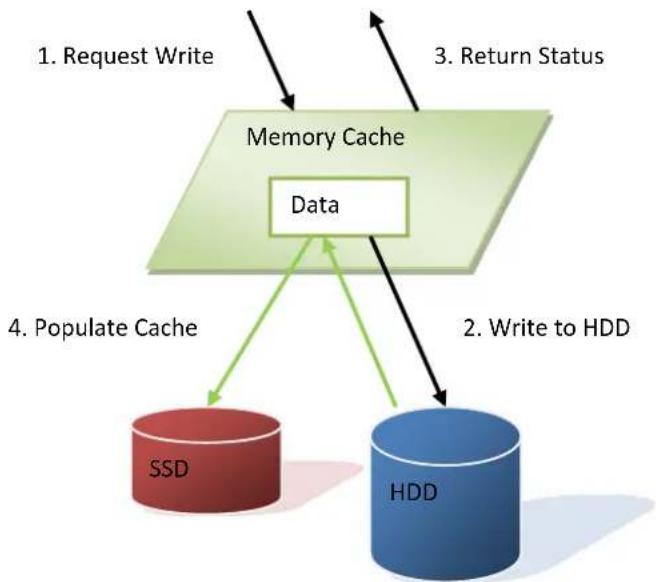
flowchart
graph TD
    A["1. Request Write"] --> B["Memory Cache"]
    C["2. Write to HDD"] --> B
    D["3. Return Status"] --> B
    E["4. Populate Cache"] --> F["SSD"]
    G["Data"] --> B
    B --> H["HDD"]
The following steps describe details about a host write:
- A host requests a write data.
- Write data to the HDD.
- Return the status to the host.
- Populate the cache to SSD.
I/O Type
The type of I/O access is a user-selectable SSD cache configuration. The user-selectable I/O type controls the SSD cache internal settings for cache block size, sub-block size, populate-on-read threshold, and populate-on-write threshold. Three pre-defined I/O types are supported; they are database, file system, and web service. The user can select an I/O type to set the SSD cache of a virtual disk. When SSD caching is enabled, the user can also change it online. But the cached data would be purged if the I/O type is changed. You may select the suitable I/O types depending on
the application to get the best performance. If the above three applications are not suitable, the last item is customization which you may set the configurations by yourself.
| I/O Type | Block Size (Sectors) | Sub-block Size (Sectors) | Populate-on-Read Threshold | Populate-on-Wrote Threshold |
| Database | 1MB (2,048) | 8KB (16) | 2 | 0 |
| File System | 2MB (4,096) | 16KB (32) | 2 | 2 |
| Web Service | 4MB (8,192) | 64KB (128) | 2 | 0 |
| Customization | 1MB/2MB/4MB | 8KB/16KB/64KB | ≥ 0 | ≥ 0 |
The block size affects the cache use and the warm up time. The cache use shows how much of the allocated cache actually holds the user data. And the warm up time is the process of how long to fill the cache. You can image that the highest cache use is obtained when all of the frequently reread data is located very close to other data that is frequently re-read. Using a larger cache block size of I/O type is more useful to performance than a smaller one. Conversely, when frequently reread data is located far from other data that is frequently reread, the lowest cache use is obtained. In this case, the lowest cache block size of I/O type allows the most user data to be cached.
The sub-block size affects the cache warm up time, too. A larger sub-block size causes a cache to fill more quickly than a smaller one, but it can also affect the response time of host I/O. Also resources occupying the system, such as CPU utilization, memory bandwidth, or channel utilization. A very high locality of reference can be more useful from a larger sub-block size than from a smaller one, especially if those blocks that are reread frequently reside in the same sub-block. This occurs when one I/O causes the sub-block to be populated and another I/O in the same sub-block gets a cache hit.
These are tradeoffs depending on the applications. Users may set them by experience to get the best performance. Here we provide a formula which can calculate the estimated warm up time.
We define that
• T: Warm up time; seconds required.
• I: Best random IOPS of HDD.
• S: I/O Size.
• D: Number of HDDs.
• C: Total SSD caching capacity.
• P: Populate-on-read or Populate-on-write threshold
We assume that random read/write from HDD to achieve the capacity of SSD should be
$$ C ^ {} P = 1 ^ {} S ^ {} D ^ {} T $$
So we can estimate the warm up time, at least.
$$ T = (C * P) / (I * S * D) $$
The real case may be longer than the estimate time. Here we take an example of the following.
• I: 250 IOPS (Random IOPS per HDD)
• S: 64KB (Web service)
D: 16 HDDs
C: 480GB (1 SSD)
• P: 2 (Populate-on-read threshold)
Warm up time T = (480GB * 2) / (250 * 64KB * 16) = 3932.16 seconds = 65.536 minutes
Configuration
Take an example of enabling SSD caching.
- After creating a virtual disk, click ▼ -> Set SSD Caching of the selected virtual disk.
- Check Enable box.
- Select the policy by drop down menu.
- Click Select Disks button, and then check the SSDs which are provided for SSD caching.
- Click OK button to enable SSD caching.

Constraints
Here are some constraints about SSD caching.
• Only SSD can be used for SSD caching space of a virtual disk.
• A SSD can be assigned to one and only one virtual disk as its caching space.
• Up to 8 SSDs can be used as a SSD cache of a virtual disk.
• Support up to 2.4TB of SSD caching space in one system.
• Support D-Link bundled SSD only. Normal SSD will be treated as ordinary drives and cannot used in SSD caching.
Troubleshooting
6
System Buzzer
The system buzzer features are listed below:
• The system buzzer initiates for 1 second when system boots up successfully.
- The system buzzer initiates continuously when an error occurs. The alarm will be stopped after the error is resolved or muted.
- The alarm will be muted automatically when the error is resolved. E.g., when RAID 5 is degraded and alarm rings immediately, user changes / adds one physical disk for rebuilding. When the rebuilding is done, the alarm will be muted automatically.
Event Notifications
Physical Disk Events
| Level | Type | Description |
| INFO | PD inserted | Diskis inserted into system |
| WARNING | PD removed | Diskis removed from system |
| ERROR | HDD read error | Diskread block error |
| ERROR | HDD write error | Diskwrite block error |
| ERROR | HDD error | Diskis disabled |
| ERROR | HDD IO timeout | Diskgets no response |
| INFO | PD upgrade started | PD[] starts upgrading firmware process. |
| INFO | PD upgrade finished | PD[] finished upgrading firmware process. |
| WARNING | PD upgrade failed | PD[] upgrade firmware failed. |
| INFO | PD RPS started L2L | Assign PDto replace PD. |
| INFO | PD RPS finished L2L | PDis replaced by PD. |
| ERROR | PD RPS failed L2L | Failed to replace PDwith PD. |
Hardware Events
| Level | Type | Description |
| WARNING | ECC single | Single-bit ECC error is detected at |
| ERROR | ECC multiple | Multi-bit ECC error is detected at |
| INFO | ECC dimm | ECC memory is installed |
| INFO | ECC none | Non-ECC memory is installed |
| INFO | SCSI bus reset | Received SCSI Bus Reset event at the SCSI Bus |
| ERROR | SCSI host error | SCSI Host allocation failed |
| ERROR | SATA enable device fail | Failed to enable the SATA pci device |
| ERROR | SATA EDMA mem fail | Failed to allocate memory for SATA EDMA |
| ERROR | SATA remap mem fail | Failed to remap SATA memory io space |
| ERROR | SATA PRD mem fail | Failed to init SATA PRD memory manager |
| ERROR | SATA revision id fail | Failed to get SATA revision id |
| ERROR | SATA set reg fail | Failed to set SATA register |
| ERROR | SATA init fail | Core failed to initialize the SATA adapter |
| ERROR | SATA diag fail | SATA Adapter diagnostics failed |
| ERROR | Mode ID fail | SATA Mode ID failed |
| ERROR | SATA chip count error | SATA Chip count error |
| INFO | SAS port reply error | SAS HBA portreply terminated abnormally |
| INFO | SAS unknown port reply error | SAS frontend reply terminated abnormally |
| INFO | FC port reply error | FC HBA portreply terminated abnormally |
| INFO | FC unknown port reply error | FC frontend reply terminated abnormally |
| INFO | Port linkup | The Portlink status is changed to Up. |
| INFO | Port linkdown | The Portlink status is changed to Down. |
EMS Events
| Level | Type | Description |
| INFO | Power install | Power() is installed |
| ERROR | Power absent | Power() is absent |
| INFO | Power restore | Power() is restored to work. |
| ERROR | Power fail | Power() is not functioning |
| WARNING | Power detect | PSU signal detection() |
| INFO | Fan restore | Fan() is restored to work. |
| ERROR | Fan fail | Fan() is not functioning |
| INFO | Fan install | Fan() is installed |
| ERROR | Fan not present | Fan() is not present |
| ERROR | Fan over speed | Fan() is over speed |
| WARNING | Thermal level 1 | System temperature() is higher. |
| ERROR | Thermal level 2 | System Overheated()!!! |
| ERROR | Thermal level 2 shutdown | System Overheated()!!! The system will auto-shutdown immediately. |
| ERROR | Thermal level 2 CTR shutdown | The controller will auto shutdown immediately, reason [Overheated)]. |
| WARNING | Thermal ignore value | Unable to update thermal value on |
| WARNING | Voltage level 1 | System voltage() is higher/lower. |
| ERROR | Voltage level 2 | System voltages() failed!!! |
| ERROR | Voltage level 2 shutdown | System voltages() failed!!! The system will auto-shutdown immediately. |
| ERROR | Voltage level 2 CTR shutdown | The controller will auto shutdown immediately, reason [Voltage abnormal()] . |
| INFO | UPS OK | Successfully detect UPS |
| WARNING | UPS fail | Failed to detect UPS |
| ERROR | UPS AC loss | AC loss for system is detected |
| ERROR | UPS power low | UPS Power Low!!! The system will auto-shutdown immediately. |
| WARNING | SMART T.E.C. | DiskS.M.A.R.T. Threshold Exceed Condition occurred for attribute: |
| WARNING | SMART fail | Disk: Failure to get S.M.A.R.T information |
| WARNING | RedBoot failover | RedBoot failover event occurred |
| WARNING | Watchdog shutdown | Watchdog timeout shutdown occurred |
| WARNING | Watchdog reset | Watchdog timeout reset occurred |
RMS Events
| Level | Type | Description |
| INFO | Console Login | <username> login from via Console UI |
| INFO | Console Logout | <username> logout from via Console UI |
| INFO | Web Login | <username> login from via Web UI |
| INFO | Web Logout | <username> logout from via Web UI |
| INFO | Log clear | All event logs are cleared |
| WARNING | Send mail fail | Failed to send event to. |
LVM Events
| Level | Type | Description |
| INFO | RG create OK | RGhas been created. |
| INFO | RG create fail | Failed to create RG. |
| INFO | RG delete | RGhas been deleted. |
| INFO | RG rename | RGhas been renamed as. |
| INFO | VD create OK | VDhas been created. |
| INFO | VD create fail | Failed to create VD. |
| INFO | VD delete | VDhas been deleted. |
| INFO | VD rename | Name of VDhas been renamed to. |
| INFO | VD read only | Cache policy of VDhas been set as read only. |
| INFO | VD write back | Cache policy of VDhas been set as write-back. |
| INFO | VD write through | Cache policy of VDhas been set as write-through. |
| INFO | VD extend | Size of VDextends. |
| INFO | VD attach LUN OK | VDhas been LUN-attached. |
| INFO | VD attach LUN fail | Failed to attach LUN to VD. |
| INFO | VD detach LUN OK | VDhas been detached. |
| INFO | VD detach LUN fail | Failed to attach LUN from bus, SCSI ID,lun. |
| INFO | VD init started | VDstarts initialization. |
| INFO | VD init finished | VDcompletes initialization. |
| WARNING | VD init failed | Failed to complete initialization of VD. |
| INFO | VD rebuild started | VDstarts rebuilding. |
| INFO | VD rebuild finished | VDcompletes rebuilding. |
| WARNING | VD rebuild failed | Failed to complete rebuild of VD. |
| INFO | VD migrate started | VDstarts migration. |
| INFO | VD migrate finished | VDcompletes migration. |
| ERROR | VD migrate failed | Failed to complete migration of VD. |
| INFO | VD scrub started | Parity checking on VDstarts. |
| INFO | VD scrub finished | Parity checking on VDcompletes withparity/data inconsistency found. |
| INFO | VD scrub aborted | Parity checking on VDstops withparity/data inconsistency found. |
| INFO | RG migrate started | RGstarts migration. |
| INFO | RG migrate finished | RGcompletes migration. |
| INFO | RG move started | RGstarts move. |
| INFO | RG move finished | RGcompletes move. |
| INFO | VD move started | VDstarts move. |
| INFO | VD move finished | VDcompletes move. |
| ERROR | VD move failed | Failed to complete move of VD. |
| INFO | VD attach LUN | LUNis attached to VD. |
| INFO | VD detach LUN | LUNis detached from VD. |
| INFO | RG activated | RGhas been manually activated. |
| INFO | RG deactivated | RGhas been manually deactivated. |
| DEBUG | VD rewrite started | Rewrite at LBAof VDstarts. |
| DEBUG | VD rewrite finished | Rewrite at LBAof VDcompletes. |
| DEBUG | VD rewrite failed | Rewrite at LBAof VDfailed. |
| WARNING | RG degraded | RGis in degraded mode. |
| WARNING | VD degraded | VDis in degraded mode. |
| ERROR | RG failed | RGis failed. |
| ERROR | VD failed | VDis failed. |
| ERROR | VD IO fault | I/O failure for stripe numberin VD. |
| DEBUG | Recoverable read error | Recoverable read error occurred at LBA-of VD. |
| WARNING | Recoverable write error | Recoverable write error occurred at LBA-of VD. |
| DEBUG | Unrecoverable read error | Unrecoverable read error occurred at LBA-of VD. |
| ERROR | Unrecoverable write error | Unrecoverable write error occurred at LBA-of VD. |
| ERROR | Config read fail | Config read failed at LBA-of PD. |
| ERROR | Config write fail | Config write failed at LBA-of PD. |
| ERROR | CV boot error adjust global | Failed to change size of the global cache. |
| INFO | CV boot global | The global cache is ok. |
| ERROR | CV boot error create global | Failed to create the global cache. |
| INFO | PD dedicated spare | Assign PDto be the dedicated spare disk of RG. |
| INFO | PD global spare | Assign PDto Global Spare Disks. |
| WARNING | PD read error | Read error occurred at LBA-of PD. |
| WARNING | PD write error | Write error occurred at LBA-of PD. |
| WARNING | Scrub wrong parity | The parity/data inconsistency is found at LBA- when checking parity on VD. |
| WARNING | Scrub data recovered | The data at LBA-is recovered when checking parity on VD. |
| WARNING | Scrub recovered data | A recoverable read error occurred at LBA- when checking parity on VD. |
| WARNING | Scrub parity recovered | The parity at LBA-is regenerated when checking parity on VD. |
| INFO | PD freed | PD has been freed from RG. |
| INFO | RG imported | Configuration of RG has been imported. |
| INFO | RG restored | Configuration of RG has been restored. |
| INFO | VD restored | Configuration of VD has been restored. |
| INFO | PD scrub started | PD starts disk scrubbing process. |
| INFO | Disk scrub finished | PD completed disk scrubbing process. |
| INFO | Large RG created | A large RG with disks included is created |
| INFO | Weak RG created | A RG made up disks across chassis is created |
| INFO | RG size shrunk | The total size of RG shrunk |
| INFO | VD erase finished | VD finished erasing process. |
| WARNING | VD erase failed | The erasing process of VD failed. |
| INFO | VD erase started | VD starts erasing process. |
| WARNING | RG disk missing | RG cannot be activated because of missing disks. |
| ERROR | PD VD read write fault | Read error at LBA-of PD and rewrite failed at LBA-of VD. |
| ERROR | PD IO retry fault | Over I/O retry limit in last 10 minutes on PD, replacing the disk is highly recommended. |
| ERROR | PD substitute L2L | Over I/O retry limit in last 10 minutes on PD, the disk is disabled for automatic rebuilding with PD. |
Snapshot Events
| Level | Type | Description |
| WARNING | Snap mem | Failed to allocate snapshot memory for VD. |
| WARNING | Snap space overflow | Failed to allocate snapshot space for VD. |
| WARNING | Snap threshold | The snapshot space threshold of VDhas been reached. |
| INFO | Snap delete | The snapshot VDhas been deleted. |
| INFO | Snap auto delete | The oldest snapshot VDhas been deleted to obtain extra snapshot space. |
| INFO | Snap take | A snapshot on VDhas been taken. |
| INFO | Snap set space | Set the snapshot space of VDto MB. |
| INFO | Snap rollback started | Snapshot rollback of VDhas been started. |
| INFO | Snap rollback finished | Snapshot rollback of VDhas been finished. |
| WARNING | Snap quota reached | The quota assigned to snapshotis reached. |
| INFO | Snap clear space | The snapshot space of VDis cleared |
iSCSI Events
| Level | Type | Description |
| INFO | iSCSI login accepted | iSCSI login fromsucceeds. |
| INFO | iSCSI login rejected | iSCSI login fromwas rejected, reason[] |
| INFO | iSCSI logout recvd | iSCSI logout fromwas received, reason]. |
Battery Backup Events
| Level | Type | Description |
| INFO | BBM start syncing | Abnormal shutdown detected, start flushing battery-backed data (KB). |
| INFO | BBM stop syncing | Abnormal shutdown detected, flushing battery-backed data finished |
| INFO | BBM installed | Battery backup module is detected |
| INFO | BBM status good | Battery backup module is good |
| INFO | BBM status charging | Battery backup module is charging |
| WARNING | BBM status fail | Battery backup module is failed |
| INFO | BBM enabled | Battery backup feature is. |
| INFO | BBM inserted | Battery backup module is inserted |
| INFO | BBM removed | Battery backup module is removed |
JBOD Events
| Level | Type | Description |
| INFO | PD upgrade started | JBODPD [] starts upgrading firmware process. |
| INFO | PD upgrade finished | JBODPD [] finished upgrading firmware process. |
| WARNING | PD upgrade failed | JBODPD [] upgrade firmware failed. |
| INFO | PD freed | JBODPD has been freed from RG. |
| INFO | PD inserted | JBODdisk is inserted into system. |
| Warning | PD removed | JBODdisk is removed from system. |
| ERROR | HDD read error | JBODdisk read block error |
| ERROR | HDD write error | JBODdisk write block error |
| ERROR | HDD error | JBODdisk is disabled. |
| ERROR | HDD IO timeout | JBODdisk gets no response |
| INFO | JBOD inserted | JBODis inserted into system |
| WARNING | JBOD removed | JBODis removed from system |
| WARNING | JBOD SMART T.E.C | JBODdisk: S.M.A.R.T. Threshold Exceed Condition occurred for attribute |
| WARNING | JBOD SMART fail | JBODdisk: Failure to get S.M.A.R.T information |
| INFO | JBOD CTR inserted | Controller() of JBODis inserted into system |
| WARNING | JBOD CTR removed | Controller() of JBODis removed from system |
| WARNING | JBOD degraded | JBODis in degraded mode. |
| INFO | PD dedicated spare | Assign JBODPDto be the dedicated spare disk of RG. |
| INFO | PD global spare | Assign JBODPDto Global Spare Disks. |
| ERROR | Config read fail | Config read error occurred at LBA--of JBODPD. |
| ERROR | Config write fail | Config write error occurred at LBA--of JBODPD. |
| DEBUG | PD read error | Read error occurred at LBA--of JBODPD. |
| WARNING | PD write error | Write error occurred at LBA--of JBODPD. |
| INFO | PD scrub started | JBODPDstarts disk scrubbing process. |
| INFO | PD scrub completed | JBODPDcompleted disk scrubbing process. |
| WARNING | PS fail | Power Supply ofin JBODis FAIL |
| INFO | PS normal | Power Supply ofin JBODis NORMAL |
| WARNING | FAN fail | Cooling fan ofin JBODis FAIL |
| INFO | FAN normal | Cooling fan ofin JBODis NORMAL |
| WARNING | Volt warn OV | Voltage ofread asin JBODis WARN OVER |
| WARNING | Volt warn UV | Voltage ofread asin JBODis WARN UNDER |
| WARNING | Volt crit OV | Voltage ofread asin JBODis CRIT OVER |
| WARNING | Volt crit UV | Voltage ofread asin JBODis CRIT UNDER |
| INFO | Volt recovery | Voltage ofin JBODis NORMAL |
| WARNING | Therm warn OT | Temperature ofread asin JBODis OT WARNING |
| WARNING | Therm warn UT | Temperature ofread asin JBODis UT WARNING |
| WARNING | Therm fail OT | Temperature ofread asin JBODis OT FAILURE |
| WARNING | Therm fail UT | Temperature ofread asin JBODis UT FAILURE |
| INFO | Therm recovery | Temperature ofin JBODis NORMAL |
| INFO | JBOD HDD path NG | Path redundancy to JBODPDis lost |
| INFO | PD RPS started L2F | Assign JBODPDto replace PD. |
| INFO | PD RPS started F2L | Assign PDto replace JBODPD. |
| INFO | PD RPS started F2F | Assign JBODPDto replace JBODPD. |
| INFO | PD RPS finished L2F | PDis replaced by JBODPD. |
| INFO | PD RPS finished F2L | JBODPDis replaced by PD. |
| INFO | PD RPS finished F2F | JBODPDis replaced by JBODPD. |
| ERROR | PD RPS failed L2F | Failed to replace PDwith JBOD %4d PD. |
| ERROR | PD RPS failed F2L | Failed to replace JBODPDwith PD. |
| ERROR | PD RPS failed F2F | Failed to replace JBODPDwith JBODPD. |
| ERROR | PD VD read write fault | Read error at LBA-of JBODPDand rewrite failed at LBA-of VD. |
| ERROR | PD IO retry fault | Over I/O retry limit in last 10 minutes on JBODPD, replacing the disk is highly recommended. |
| ERROR | PD substitute L2F | Over I/O retry limit in last 10 minutes on PD, the disk is disabled for automatic rebuilding with JBODPD. |
| ERROR | PD substitute F2L | Over I/O retry limit in last 10 minutes on JBODPD, the disk is disabled for automatic rebuilding with PD. |
| ERROR | PD substitute F2F | Over I/O retry limit in last 10 minutes on JBODPD, the disk is disabled for automatic rebuilding with JBODPD. |
System Maintenance Events
| Level | Type | Description |
| INFO | System shutdown | System shutdown. |
| INFO | System reboot | System reboot. |
| INFO | System console shutdown | System shutdown from via Console UI |
| INFO | System web shutdown | System shutdown from via Web UI |
| INFO | System button shutdown | System shutdown via power button |
| INFO | System LCM shutdown | System shutdown via LCM |
| INFO | System console reboot | System reboot from via Console UI |
| INFO | System web reboot | System reboot from via Web UI |
| INFO | System LCM reboot | System reboot via LCM |
| INFO | FW upgrade start | System firmware upgrade starts. |
| INFO | FW upgrade success | System firmware upgrade succeeds. |
| WARNING | FW upgrade failure | System firmware upgrade is failed. |
| ERROR | IPC FW upgrade timeout | System firmware upgrade timeout on another controller |
| INFO | Config imported | config imported |
HAC Events
| Level | Type | Description |
| INFO | RG owner changed | The preferred owner of RGhas been changed to controller. |
| INFO | Force CTR write through | Controllerforced to adopt write-through mode on failover. |
| INFO | Restore CTR cache mode | Controllerrestored to previous caching mode on failback. |
| INFO | Failover complete | All volumes in controllercompleted failover process. |
| INFO | Failback complete | All volumes in controllercompleted failback process. |
| INFO | CTR inserted | Controlleris inserted into system |
| ERROR | CTR removed | Controlleris removed from system |
| ERROR | CTR timeout | Controllergets no response |
| ERROR | CTR lockdown | Controlleris locked down |
| ERROR | CTR memory NG | Memory size mismatch |
| ERROR | CTR firmware NG | Firmware version mismatch |
| ERROR | CTR lowspeed NG | Low speed inter link is down |
| ERROR | CTR highspeed NG | High speed inter link is down |
| ERROR | CTR backend NG | SAS expander is down |
| ERROR | CTR frontend NG | FC IO controller is down |
| INFO | CTR reboot FW sync | Controller reboot, reason [Firmware synchronization completed] |
Clone Events
| Level | Type | Description |
| INFO | VD clone started | VDstarts cloning process. |
| INFO | VD clone finished | VDfinished cloning process. |
| WARNING | VD clone failed | The cloning in VDfailed. |
| INFO | VD clone aborted | The cloning in VDwas aborted. |
| INFO | VD clone set | The clone of VDhas been designated. |
| INFO | VD clone reset | The clone of VDis no longer designated. |
| WARNING | Auto clone error | Auto clone task:. |
| WARNING | Auto clone nosnap | Auto clone task: Snapshotis not found for VD. |
Replication Events
| Level | Type | Description |
| INFO | rep portal enabled | Replication portal is enabled |
| INFO | rep portal disabled | Replication portal is disabled |
| INFO | VD replicate started | VDstarts replication process. |
| INFO | VD replicate finished | VDfinished replication process. |
| WARNING | VD replicate failed | The replication in VDfailed. |
| INFO | VD replicate aborted | The replication in VDwas aborted. |
| INFO | VD set as replication | VDhas been configured as a replication. |
| INFO | VD set as RAID | VDhas been configured as a RAID volume. |
| INFO | VD replication set | The replication of VDhas been designated. |
| INFO | VD replication reset | The replication of VDis no longer designated. |
| WARNING | Auto rep not enable | Auto Replica task: Replication is not enabled for VD. |
| WARNING | Auto rep error | Auto Replication task:. |
| WARNING | Auto rep no snap | Auto Replication task: Snapshotis not found for VD. |
| INFO | Source replicate started | Remote VDstarts replicating to VD. |
| INFO | Source replicate finished | Remote VDfinished replication to VD. |
| INFO | Source replicate failed | Remote VDfailed replication to VD. |
| INFO | Source replicate aborted | Remote VDaborted replication to VD. |
Thin Provisioning Events
| Level | Type | Description |
| WARNING | RG threshold hit | The used capacity of RGexceedspercent. |
| INFO | RAID set created | RAID sethas been added into RG. |
| INFO | RAID set deleted | RAID setwas deleted from RG. |
| INFO | VD reclaim started | VDstarts space reclamation process. |
| INFO | VD reclaim completed | VDfinished space reclamation process. |
| WARNING | VD reclaim aborted | The space reclamation in VDwas aborted. |
- DEBUG level events are displayed in download event log file only.
Software Application
7
Microsoft iSCSI Initiator
Here is the step by step process to setup Microsoft iSCSI Initiator. Please visit Microsoft website for the latest iSCSI initiator. This example is based on Microsoft Windows Server 2008 R2.
Connect to iSCSI Target
- Run Microsoft iSCSI Initiator.
- Input IP address or DNS name of the target. And then click Quick Connect button.

- Select the target name, and then click the Done button.
- It can connect to an iSCSI disk now.
Setup MPIO
- If running MPIO, please continue.
- Click Discovery tab to connect the second path.
- Click Discover Portal button. Enter the IP address or DNS name of the target.
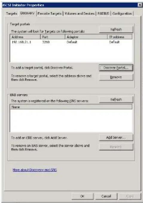

- Click OK button.
- Click Targets tab, select the second path, and then click Connect button.
- Enable Enable multi-path checkbox. Then click OK button.
- Done, it can connect to an iSCSI disk with MPIO.
Setup MC/S
- If running MC/S, please continue.
- Select one target name, click Properties button.
- Click MCS button to add additional connections.
- Click Add button.
- Click Advanced button.
- Select Initiator IP and Target portal IP, and then click OK button.
- Click Connect button.
- Click OK button.


- Done.
Disconnect
- Select the target name, click Disconnect button, and then click Yes button.
- Done, the iSCSI device disconnected successfully.
Glossary and Acronym List
Common Terminology
| Item | Description |
| RAID | Redundant Array of Independent Disks. There are different RAID levels with different degree of data protection, data availability, and performance to host environment. |
| PD | The Physical Disk belongs to the member disk of one specific RAID group. |
| RG | Raid Group. A collection of removable media. One RAID group consists of a set of virtual disks and owns one RAID level attribute. |
| VD | Virtual Disk. Each RAID group could be divided into several virtual disks. The virtual disks from one RAID group have the same RAID level, but may have different volume capacity. |
| LUN | Logical Unit Number. A logical unit number (LUN) is a unique identifier which enables it to differentiate among separate devices (each one is a logical unit). |
| GUI | Graphic User Interface. |
| RAID cell | When creating a RAID group with a compound RAID level, such as 10, 30, 50 and 60, this field indicates the number of subgroups in the RAID group. For example, 8 disks can be grouped into a RAID group of RAID 10 with 2 cells, 4 cells. In the 2-cell case, PD {0, 1, 2, 3} forms one RAID 1 subgroup and PD {4, 5, 6, 7} forms another RAID 1 subgroup. In the 4-cells, the 4 subgroups are physical disk {0, 1}, physical disk {2, 3}, physical disk {4, 5} and physical disk {6,7}. |
| WT | Write-Through cache-write policy. A caching technique in which the completion of a write request is not signaled until data is safely stored in non-volatile media. Each data is synchronized in both data cache and accessed physical disks. |
| WB | Write-Back cache-write policy. A caching technique in which the completion of a write request is signaled as soon as the data is in cache and actual writing to non-volatile media occurs at a later time. It speeds up system write performance but needs to bear the risk where data may be inconsistent between data cache and the physical disks in one short time interval. |
| RO | Set the volume to be Read-Only. |
| DS | Dedicated Spare disks. The spare disks are only used by one specific RAID group. Others could not use these dedicated spare disks for any rebuilding purpose. |
| LS | Local Spare disks. The spare disks are only used by the RAID groups of the local enclosure. Other enclosure could not use these local spare disks for any rebuilding purpose. |
| GS | Global Spare disks. It is shared for rebuilding purpose. If some RAID groups need to use the global spare disks for rebuilding, they could get the spare disks out from the common spare disks pool for such requirement. |
| DG | DeGraded mode. Not all of the array’s member disks are functioning, but the array is able to respond to application read and write requests to its virtual disks. |
| SCSI | Small Computer Systems Interface |
| SAS | Serial Attached SCSI |
| S.M.A.R.T. | Self-Monitoring Analysis and Reporting Technology |
| WWN | World Wide Name |
| HBA | Host Bus Adapter |
| SES | SCSI Enclosure Services |
| NIC | Network Interface Card |
| BBM | Battery Backup Module |
iSCSI / SAS Terminology
| Item | Description |
| FC-P2P | Point-to-Point |
| FC-AL | Arbitrated Loop |
| FC-SW | Switched Fabric |
| iSCSI | Internet Small Computer Systems Interface |
| LACP | Link Aggregation Control Protocol |
| MPIO | Multi-Path Input/Output |
| MC/S | Multiple Connections per Session |
| MTU | Maximum Transmission Unit |
| CHAP | Challenge Handshake Authentication Protocol. An optional security mechanism to control access to an iSCSI storage system over the iSCSI data ports. |
| iSNS | Internet Storage Name Service |
| SAS | Serial Attached SCSI |
Dual Controller Terminology
| Item | Description |
| SBB | Storage Bridge Bay. The objective of the Storage Bridge Bay Working Group (SBB) is to create a specification that defines mechanical, electrical and low-level enclosure management requirements for an enclosure controller slot that will support a variety of storage controllers from a variety of independent hardware vendors (“IHVs”) and system vendors. |
| 6G MUX | D-Link bridge board is for SATA II disk to support dual controller mode. |
Index
A
Active Sessions....58
Connection Details....59
Disconnect....59
B
BBM (Battery Backup Module) 22
Buzzer....138
C
CHAP (Challenge Handshake Authentication Protocol).....56
CHAP Accounts 59
Create User....60
Delete User....60
Modify User Information 60
Clone....115
Change Replication Options....70
Clear Clone 70,118
Cloning Options....117
Constraint....118
Schedule Clone 70,116
Set Clone....70, 115
Start Clone 70,116
Stop Clone....70,116
Clone Options
Restart the task an hour later if it failed 118
Snapshot Space 117
Threshold 117
Configuration Backup 87
Export....88
Import....88
D
Disk 90
Drive Slot Numbering 21
Dual Controllers....107
E
Email Notification Settings 49
Send Test Email 49
Enclosure Management 78
Entity and iSCSI Settings 55
Event Log....84,138
Clear 84
Download....84
Mute Buzzer 84
F
Fast Rebuild....129
Configuration....130
Constraint....130
Solution 129
Firmware Synchronization....86
G
GUI (Graphic User Interface) 32
H
Hardware Monitor....78
Auto Shutdown....79
Host Port Configuration....52
|
Indicators and Icons 34
iSCSI....90
iSCSI (Internet SCSI)....19
iSCSI Concepts....19
iSCSI Configuration....52
iSCSI Initiator
Connect....148
Disconnect....150
MC/S 149
MPIO 149
iSCSI Initiator....148
iSCSI Nodes....56
Authentication Method....56
Change Portal 57
Rename Alias ....58
iSNS (Internet Storage Name Service)....55
J
JBOD Expansion....102
Connecting JBOD....102
Upgrade Firmware....103
Jumbo Frame....54
L
LACP (Link Aggregation Control Protocol)....53, 106
LCM (LCD Control Module)....30
Log and Alert Settings
Device Buzzer 52
Log and Alert Settings....50
Admin Interface and Front Display Alerts 52
SNMP Trap Settings 51
System Server Settings....51
Windows Messenger....51
Logical Units 75
Attach LUN....70, 73, 75
Detach LUNs....70, 73, 75
List LUNs....70, 73
Login Settings....48
Auto Logout 49
Change Admin Password 49
Change User Password....49
Login Lock 49
LUN (Logical Unit Number)....75
M
MC/S (Multiple Connections per Session) 104, 122
MPIO (Multi Path Input/Output).... 104, 122
MTU (Maximum Transmission Unit)....54
N
Network Settings 47
DNS Server Address 48
Enable dual management ports....48
IP Address....48
MAC Address 48
Service Ports 48
Network Setup 52
Disable Jumbo Frames 54
Enable Jumbo Frames 54
iSCSI Bonding Settings....53
iSCSI IP Address Settings....54
Make Default Gateway 54
Ping Host....55
Remove Default Gateway 54
Reset Port 55
Set VLAN ID 53
NTP (Network Time Protocol) 47
P
PCP (Priority Code Point) 54
Performance Monitor....90
Physical Disks 61
Disk Check Report 62
Disk Health Check 62
Disk Scrub....62
More Information....62
Read Error Cleared....62
Set Dedicated Spare 62
Set Free Disk....62
Set Global Spare....62
Set Local Spare 62
Turn on/off the Indication LED....62
Upgrade....62
Q
Replication Options
Restart the task an hour later if it failed 126
Snapshot Space 126
Threshold....126
Replications 76, 119
Add Connection....78, 122
Add Path....78, 122
Change Replication Options....126
Create 77,119
Delete 78,126
Delete Connection 78,122
Delete Path 122
Replication Options....77, 125
Rebuild 77
Schedule 78,124
Set Task Shaping 78,123
Shaping Setting Configuration 77, 123
Start 77,122
Stop 78,122
Thin....96
Space Reclamation 70
Quick Installation....35
R
RAID Concepts....17
RAID Group Policy
Delete 66
Modify....66
RAID Groups....63
Activate 64
Add Policy....65
Add RAID Set 65
Change Preferred Controller....64
Change RAID Options....64
Create 64
Deactivate....64
Delete 64
Migrate RAID Level....64, 93
More Information 65
Move RAID Level....64, 93
Verify Parity....64
RAID Levels....18
RAID Set
List Disks....66
Move RAID Level....66
Remove....66
Reboot and Shutdown....89
Replication....76, 119
Reset to Factory Defaults....87
Roaming....102
S
S.M.A.R.T. (Self-Monitoring Analysis and Reporting
Technology)....82
SAS (Serial Attached SCSI) 20
SAS Concepts....20
Serial Console....29
SES (SCSI Enclosure Services) 81
Disable....81
Enable....81
Snapshots....72,110
Attach LUN 70, 73, 75
Cleanup Snapshots....70, 73, 111
Constraint....113
Delete 73
Detach LUNs....70, 73, 75
List LUNs....70, 73
List Snapshots 70
Rollback....73,112
Schedule Snapshots....70, 73, 112
Set Quota....73
Set Snapshot Space 70, 73
Take a Snapshot 70, 73, 110
Unexpose....73
SSD Caching 130
Configuration....136
Costraint....137
I/O Type....134
Methodology....131
Populating the Cache....132
Read/Write Cache Cases....132
Solution....131
SSH (Secure Shell)....29
System Configuration....46
System Information 82
Download System Information 83
System Installation and Deployment 22
System Maintenance....82
System Settings 47
Date and Time....47
System Identification 47
System Name 47
T
Thin Provisioning....96
Trunking....53,106
U
Upgrade 85
Controller Mode....86,109
Controller Module Firmware Update....86
JBOD Firmware Update....86, 103
UPS (Uninterruptible Power Supply) 80
V
Virtual Disks....68
Attach LUN 70, 73, 75
Change Replication Options....70
Cleanup Snapshots....70, 73
Clear Clone....70
Cloning Options....69
Create 69
Delete 69
Detach LUNs....70, 73, 75
Extend 69,95
List LUNs....70, 73
List Snapshots....70
More Information 70
Schedule Clone....70
Schedule Snapshots....70, 73
Set Clone 70
Set Properties....69
Set Snapshot Space....70, 73
Set SSD Caching 69
Space Reclamation 70
Start Clone....70
Stop Clone....70
Take a Snapshot....70, 73
Verify Parity....69
VLAN ID 54
Volume Configuration....60
Volume Creation Wizard 40
Volume Rebuild....92
Volume Recovery 92
Volume Relationship 18
Volume Restoration 88
Restore....89
W
Web UI (Web User Interface)....32

- Preface
- 0
- About This Manual
- CAUTION:
- Tips and Cautions
- Conventions
- Contents
- Chapter 0 PREFACE....3
- Chapter 1 OVERVIEW ....10
- Chapter 2 INSTALLATION....21
- Chapter 3 QUICK SETUP....29
- Chapter 4 BASIC CONFIGURATION ....44
- Chapter 5 ADVANCED OPERATIONS....92
- Overview
- 1
- Product Overview
- Model Comparison
- Package Contents
- Hardware
- Front View
- Disk Drive Assembly
- 3TB / 6G MUX Board Limitation
- Rear View
- RAID Concepts
- RAID Levels
- Volume Relationship
- iSCSI Concepts
- SAS Concepts
- Installation
- 2
- Installation Overview
- Drive Slot Numbering
- TIP:
- System Installation and Deployment
- Power ON / OFF
- Power on the System
- Power off the System
- Shutdown using LCD:
- On the LCD:
- Shutdown using Web UI:
- Using the Web UI:
- Shutdown using Power button:
- Quick Setup
- 3
- Management Interfaces
- Serial Console
- Secure Shell Remote Access
- LCD
- Web UI
- How to Use the Guided Configurations
- Quick Installation Tool
- Quick Installation
- Step 1: System Settings
- Volume Creation Wizard
- Basic Configuration
- 4
- Interface Hierarchy
- System Configuration
- System Settings
- Network Settings
- Change Network Settings
- MAC Address
- IP Address
- DNS Server Address
- Service Ports
- Login Settings
- Change Login Options and Passwords
- Login Options
- Admin Password
- User Password
- Email Notification Settings
- Configure Email Notification Settings
- Log and Alert Settings
- SNMP Trap Settings
- Windows Messenger
- Syslog Server Settings
- Admin Interface and Front Display Alerts
- Device Buzzer
- Host Port / iSCSI Configuration
- Network Setup
- Set VLAN ID - LAN1
- iSCSI IP Address Settings
- Entity and iSCSI Settings
- iSCSI Nodes
- Change Network Portal
- Assign or Change LAN Portal
- iSCSI Alias
- Add or change iSCSI alias.
- Active Sessions
- CHAP Accounts
- Challenge Handshake Authorization Protocol(CHAP).
- Volume Configuration
- Physical Disks
- RAID Groups
- Standby:
- Read-Ahead:
- Command Queuing:
- Virtual Disks
- Priority:
- Bg Rate:
- AV-Media Mode:
- 。 Type:
- Click Create button.
- Snapshots
- Logical Units
- the controller has iSCSI ports.)
- Replication
- Enclosure Management
- Hardware Monitor
- UPS
- SES
- SCSI Enclosure Services (SES)
- S.M.A.R.T.
- System Maintenance
- System Information
- Event log
- Download Event Logs
- Upgrade
- Firmware Synchronization (Only available in Dual controller models)
- Reset to Factory Defaults
- Configuration Backup
- Volume Restoration
- Reboot and Shutdown
- Performance Monitor
- Disk
- iSCSI
- Advanced Operations
- 5
- Volume Rebuild
- Migrate and Move RAID Groups
- Extend Virtual Disks
- Thin Provisioning
- The Benefits of Thin provisioning
- Features Highlight
- Thin Provisioning Options
- Thin Provisioning Case
- Disk Roaming
- JBOD Expansion
- Connecting JBOD
- Upgrade Firmware
- MPIO and MC/S
- MPIO
- MC/S
- Difference
- Trunking and LACP
- LACP
- The usage occasion of LACP:
- Trunking
- The usage occasion of Trunking:
- Dual Controllers
- Perform I/O
- Ownership
- Controller Status
- Change Controller Mode
- Recommend iSNS Server
- Take a Snapshot
- Cleanup Snapshots
- Schedule Snapshots
- Rollback
- CAUTION: Before executing rollback, it is better that the disk is unmounted on the host computer for flushing data from cache.
- Snapshot Constraint
- Clone
- Setup Clone
- Start and Stop Clone
- Schedule Clone
- Cloning Options
- Clear Clone
- Clone Constraint
- Create Replication Task
- Start and Stop Replication Task
- Task Shaping
- Schedule Replication Task
- Replication Options
- Delete Replication Task
- Clone Transfers to Replication
- Fast Rebuild
- Solution
- Configuration
- Constraint
- SSD Caching (licensing fee required)
- Methodology
- Populating the Cache
- Read/Write Cache Cases
- I/O Type
- We define that
- Constraints
- Troubleshooting
- 6
- System Buzzer
- Event Notifications
- Software Application
- 7
- Microsoft iSCSI Initiator
- Connect to iSCSI Target
- Setup MPIO
- Setup MC/S
- Disconnect
- Glossary and Acronym List
- Index
- A
- B
- C
- D
- E
- F
- G
- H
- |
- J
- L
- M
- N
- P
- Q
- R
- S
- T
- U
- V
- W
Brand : D-LINK
Model : DSN-6210
Category : Disk array