
DigitalMedia DMPS3-200-C - Wireless presenter Crestron - Free user manual and instructions
Find the device manual for free DigitalMedia DMPS3-200-C Crestron in PDF.


| Product Type | DigitalMedia Presentation System |
| Brand | Crestron |
| Model | DMPS3-200-C |
| Category | Wireless Presenter |
| Dimensions (W x H x D) | 17.2 in x 3.5 in x 10.5 in (437 mm x 89 mm x 267 mm) |
| Weight | 12.5 lb (5.7 kg) |
| Power Supply | 100-240VAC, 50/60Hz, 150W |
| Video Inputs | 2x HDMI, 2x DigitalMedia (DM) inputs |
| Video Outputs | 1x HDMI, 1x DM output |
| Audio Inputs | 2x mic/line inputs (balanced), 1x line input |
| Audio Outputs | 1x line output, 1x amplified speaker output |
| Wireless Presentation | Supports AirMedia (AM-100/200) for wireless screen sharing |
| Control System | Built-in 3-Series control engine |
| Ethernet | 1x 10/100/1000 Mbps |
| USB | 1x USB 2.0 host |
| Maintenance & Cleaning | Clean with dry cloth; avoid liquids; keep vents clear |
| Safety | UL/CE listed; operate in dry environment; disconnect power before servicing |
| Spare Parts & Repairability | Contact Crestron authorized service; no user-serviceable parts |
| Operating Temperature | 32°F to 104°F (0°C to 40°C) |
| Included Accessories | Power cord, mounting brackets, QuickStart guide |
Frequently Asked Questions - DigitalMedia DMPS3-200-C Crestron
User questions about DigitalMedia DMPS3-200-C Crestron
0 question about this device. Answer the ones you know or ask your own.
Ask a new question about this device
Download the instructions for your Wireless presenter in PDF format for free! Find your manual DigitalMedia DMPS3-200-C - Crestron and take your electronic device back in hand. On this page are published all the documents necessary for the use of your device. DigitalMedia DMPS3-200-C by Crestron.
USER MANUAL DigitalMedia DMPS3-200-C Crestron
Crestron product development software is licensed to Crestron dealers and Crestron Service Providers (CSPs) under a limited non-exclusive, non-transferable Software Development Tools License Agreement. Crestron product operating system software is licensed to Crestron dealers, CSPs, and end-users under a separate End-User License Agreement. Both of these Agreements can be found on the Crestron website at www.crestron.com/legal/software_license_agreement.
The specific patents that cover Crestron products are listed at patents.crestron.com.
Crestron, the Crestron logo, .AV Framework, Crestron Fusion, DigitalMedia, Fusion RV, and SystemBuilder are either trademarks or registered trademarks of Crestron Electronics, Inc. in the United States and/or other countries. IOS is either a trademark or registered trademark of Cisco Technology, Inc. in the United States and/or other countries. iPad and Macintosh are either trademarks or registered trademarks of Apple, Inc. in the United States and/or other countries. Wi-Fi is either a trademark or registered trademark of Wi-Fi Alliance in the United States and/or other countries. Windows is either a trademark or registered trademark of Microsoft Corporation in the United States and/or other countries. Other trademarks, registered trademarks, and trade names may be used in this document to refer to either the entities claiming the marks and names or their products. Crestron disclaims any proprietary interest in the marks and names of others. Crestron is not responsible for errors in typography or photography.
This document was written by the Technical Publications department at Crestron. ©2014 Crestron Electronics, Inc.
Contents
DMPS .AV Framework Base Software 1
Introduction .... 1
Interface Setup....2
TSW-752 2
Crestron App for iPad (CRESTRON-APP-PAD) 4
XPanel 6
Fusion RV 6
System Configuration 10
General 11
Input 12
Output....13
Program Setup 14
Main Screen....14
Source Selection....15
DMPS .AV Framework Base Software
Introduction
The Crestron ® DMPS3 Series of DigitalMedia ™ Presentation Systems comes with the built-in .AV Framework ™ Base Program that enables complete system configuration and control.
The latest version of the program and all projects are available on the product page for each DMPS3 model. The zipped package file includes the following:
• The .AV Framework Base Program
• The TSW-752 .AV Framework Project
- The Xpanel .AV Framework Project and installer files for Macintosh and Windows
- The iPad ® .AV Framework Project
A special version of the TSW-752 Touch Screen (TSW-752-B-DMPS3 PAK KIT) is available for use with the DMPS3 Series, which provide a simple and elegant interface.
Interface Setup
This section provides information on how to connect each interface to the control system.
TSW-752
To connect a TSW-752, use the following procedure:
NOTE: The .AV Framework Base Program requires IP ID 03 from the TSW-752. Out of the box, the value should already be set.
- On the Setup menu, touch IP Table Setup to display the Ethernet Setup - IP Table menu. The Ethernet Setup - IP Table menu displays up to four IP table settings, each of which has an Online indicator.
Ethernet Setup - IP Table Menu

- To add or edit an entry, touch the Add/Edit button to its left. The Ethernet Setup - Edit IP Table Entry screen is displayed
Ethernet Setup - Edit IP Table Entry Screen

- Touch the field below CIP ID to display the on-screen hex keypad.
Edit CIP ID Screen

- Use the keypad to make the new entry. Touch Save to save a new entry or

to return to the Ethernet Setup - Edit IP Table Entry screen.
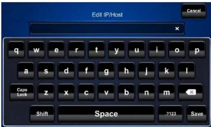
- Touch the field below IP Address/Hostname to display the on-screen keyboard.
Edit IP/Host Screen
-
Enter the IP address or hostname of your DMPS control system using the on-screen keyboard. Touch Save to save a new entry and return to the Ethernet Setup – Edit IP Table Entry screen. Touch Cancel to return to the Ethernet Setup – Edit IP Table Entry screen.
-
On the Ethernet Setup – Edit IP Table Entry screen, touch Save Entry to save the current entry or Delete Entry to clear it.
Crestron App for iPad (CRESTRON-APP-PAD)
NOTE: The form at www.crestron.com/crestronmobilesetup should be completed by an authorized Crestron installer if the customer is to configure the device. Upon completion, the instructions in this guide are e-mailed to the customer to provide assistance with the installation and startup of the app from the device.
To connect with the Crestron App for iPad app, use the following procedure:
NOTE: The .AV Framework Base Program requires IP ID 04 from this app.
- On the home screen, tap the Crestron swirl logo to start the app. A list of systems is displayed. When configuring the app for the first time, the screen appears empty.

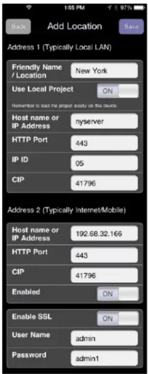
- Tap + to configure a system. The Add Location screen is displayed.
Add Location Screen
-
In the Address 1 (Typically Local LAN) section, enter the configuration information for a Wi-Fi ® connection.
-
Tap the Friendly Name / Location field and enter the name or location of the DMPS system to be connected. The field is for user reference only and is not a host name.
- If the iOS device is to host the project, tap Use Local Project until ON is displayed. If using the control system to host the project, tap Use Local Project until OFF is displayed.
- Tap the Host Name or IP Address field, and enter the host name or IP address of the DMPS system.
NOTE: If using DHCP, enter a host name rather than an IP address as the DHCP server may change the IP address periodically.
- Tap the HTTP Port field and ensure it is set to 80.
-
Tap the IP ID field and ensure it is set to 04.
• Tap the CIP field and ensure it is set to 47194. -
Tap Save. The setup screen is displayed, listing the control system that has been added.
XPanel
To connect with XPanel, use the following procedure:
NOTE: The .AV Framework Base Program requires IP ID 05 from XPanel.
-
Install XPanel by running Crestron XPanel installer.air (for Macintosh) or Crestron XPanel installer.exe (for Windows).
-
Launch the XPanel project by double-clicking dmps_autoconfiguration_xpanel_XX.c3p.
-
Access the configuration screen by selecting Options > Host Settings.
-
Enter the IP address of the control system and set the IP ID to 05.
Configuration Screen

Fusion RV
Connect
To connect with Fusion RV ® , use the following procedure:
NOTE: The .AV Framework Base Program requires IP ID F1 from Fusion RV.
- Log in to Crestron Fusion ® .
- From the Crestron Fusion header tab, click Open.
Crestron Fusion Header Tab

- From the pull-down tab, click Setup.
Pull-Down Tab

- Click the + symbol next to the Root node to expand the tree. Click the Rooms node to expand the tree again.
Root Node

- Click Add. From the drop-down list, click Add Room. The Add - Room to Root dialog box opens.
Add Drop-Down List

Add - Room to Root Dialog Box
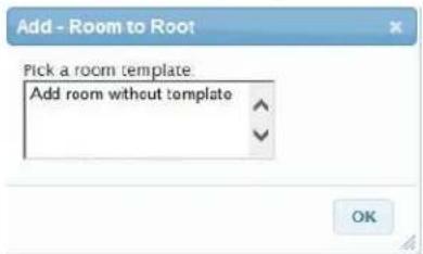
- Click Add room without template and then click OK. The Add Room to 'Rooms' window opens with the Room Details tab selected.
Room Details Tab

-
Enter information into the required fields as indicated by the red asterisks. Enter optional information as desired.
-
Click the Scheduling Details tab.
-
In the Server Access field, select RoomView Calendar from the drop-down list.
NOTE: The user can change to another scheduling calendar at a later time.
- Click the Processors tab and then click Add. The Add Processor to 'Room' dialog box opens.
Processors Tab

Add Process to 'Room' Dialog Box

- Enter information into the required fields as indicated by the red asterisks. Enter optional information as desired.
NOTE: If the Discover Symbols check box is selected in the Add Processor to 'Room' dialog box and the control program symbol being used is version 7.2 or higher, the Symbol Discover feature automatically imports the symbol information into the Crestron Fusion database.
NOTE: In SystemBuilder™, the Symbol Discover feature is not supported on symbols below version 7.2.
- Click Save & Close to return to the Processors tab.
Control and Monitor
Room monitoring and control in Crestron Fusion use the following attributes:
Controls (Read/Write)
| Type | Function |
| Digital | System On |
| Digital | System Off |
| Digital | System Mute Toggle |
Monitors (Read Only)
| Type | Function |
| Digital | System Power |
| Digital | System Muted |
| Analog | Program Volume Level |
| Serial | Fusion Error Msg |
| Serial | Fusion Log Text |
| Serial | Input 1 Source Name |
| Serial | Input 2 Source Name |
| Serial | Input 3 Source Name |
| Serial | Input 4 Source Name |
| Serial | Input 5 Source Name |
| Serial | Input 6 Source Name |
| Serial | Input 7 Source Name |
| Serial | Input 8 Source Name |
| Serial | Input 9 Source Name |
| Serial | Input 10 Source Name |
Monitor the assets connected to the system using the following attributes:
Displays 1-4 (Read Only)
| Type Status | |
| Digital | Display Power |
| Digital | Display Online |
| Digital | Display Offline Timeout Alert |
Touch Screen (Read Only)
| Type | Status |
| Digital | Touch Screen Online |
System Configuration
Once connected to a DMPS, prior to setup, the initial screen appears as shown in the following illustration.
Initial Screen

Touch the 🎨 (gear) icon to the right of the 🎨 (power) button to display the System Configuration menu. If the gear icon is not visible on the main screen, touch and hold the bottom right corner of the screen for 10 seconds to display the System Configuration menu.
System Configuration Menu

The System Configuration menu contains buttons to select the appropriate configuration screen. There is a General entry, plus an entry for each input and output.
The menu also contains a Hide Settings Button check box which, when checked, hides the gear icon normally visible to the right of the power button, in the lower left corner of the main screen.
Touch Cancel & Exit to return to the main screen without changing any settings. Touch Save & Exit to save all changes before returning to the main screen.
General
Touch General, and then use the Name text box to enter the system name you want to display on the main screen.
NOTE: When the text box is touched, an on-screen keyboard appears on the bottom of the screen and a Dismiss Keyboard button becomes visible. Touch Dismiss Keyboard to remove the keyboard from the screen.
System Configuration - General Screen

Input
Touch one of the input buttons to adjust the input's settings.
System Configuration - Input 1 Screen

Use the Name text box to enter the input name you want to display on the source selection screen (refer to page 15).
The Enabled check box determines whether this input is displayed on the source selection screen. By default, the box is checked to enable the display of this input.
Touch the Icon button to display the icon selection screen.
Icon Selection Screen
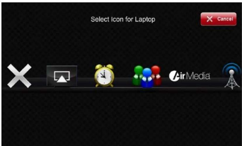
Swipe the array of icons (left or right) to move through the list. Touch an icon to assign it as the icon for the selected input.
Output
Touch Output 1 to adjust the settings of Output 1.
System Configuration - Output 1 Screen

NOTE: The screen above shows only one output. If a unit has multiple outputs, those outputs are also available for selection and configuration.
Use the Name text box to enter the output name you want to display on the main screen.
The Enabled check box determines whether the output is displayed on the main screen. By default, the box is checked to enable the display of the output.
NOTE: There must be at least one enabled output. On DMPS units with only one output, it cannot be disabled.
The Allow Audio check box determines whether audio is sent to the display as well as to the program output. By default, the box is not checked, so audio is sent only to the program output.
Use Display Type to select the type of display being used.
When a display is selected, the DMPS sends a power command to turn the display on or off with the system. The Display Power On command is sent when a source is selected. The Power Off command is sent after the system shutdown is confirmed.
NOTE: The power commands are sent via RS-232 using either the output of the "DM Roombox" or the COM A port on the DMPS. Both outputs are active simultaneously, but to prevent feedback loops, only one at a time can be connected.
Program Setup
Main Screen
The main screen is shown below. Touch the ⏻ (power) button to turn on the DMPS.
Main Screen

The Audio check boxes are used to select the audio for the room. Check the box under the source to route its audio to the outputs. (If there is only one output, there is no Audio check box.)
The right side of the main screen contains the volume controls and a volume gauge to provide visual indication of the volume setting. The audio mute control toggles between off and on, as shown in the first two illustrations below. The volume up and down controls adjust the program audio level.

Audio mute toggle (in off position)

Audio mute toggle (in on position)

Volume up control

Volume down control
Source Selection
Touch the output button (in this example, the output button is assigned the name "Projector") to display the source selection screen.
Source Selection Screen

All enabled inputs are shown on this screen. Touch an input to route its video to the output while the associated audio is routed to the program output.

CRESTRON®
Crestron Electronics, Inc.
15 Volvo Drive Rockleigh, NJ 07647 (2040690)
Tel: 888.CRESTRON 11.14
Fax: 201.767.7576
www.crestron.com

Operations Guide - DOC. 7646C
Specifications subject to
change without notice.
Brand : Crestron
Model : DigitalMedia DMPS3-200-C
Category : Wireless presenter